rooftop package units technical manual - rooftops... · status of unit, thus providing maximum...
TRANSCRIPT

1 Alliance reserves the right to discontinue or change the specifications or designs at any time without notices and without incurring
obligations.
Rooftop Package Units
Technical Manual
Applicable Models: CSU 26 RTN1
CSU 35 RTN1
CSU 53 RTN1
CSU 70 RTN1
CSU 98 RTN1

2 Alliance reserves the right to discontinue or change the specifications or designs at any time without notices and without incurring
obligations.
1. Features
1. Anti-corrosion features
Reinforced resistance to corrosion has been achieved by using galvanized
plate, coated with synthetic paint (which has passed a 1000-hour salt spray
test). The result is easy maintenance combined with long-term durability.
2. The adoption of protection systems
2.1 Compressor protection
New protection systems ensure high-pressure protection, low-pressure
protection and protection against current fluctuations, safeguarding compressor
durability. An independent system, (except for protection of sequence and
wired controller output) ensures compressor protection. Once a compressor
protection is energized, the corresponding compressor will stop, while others
continue to operate.
2.2Fan motor
Fan motors for the evaporator have over-heat protection and over-current protection function, while fan motors
for the condenser have a temperature controller protection function.
3. Energy saving design
3.1 High-efficiency compressor
Using advanced compressor technology, heat exchanger and optimum connection piping, the compressor can
start up under low power input, providing maximum reliability, efficiency and quiet operation.
Two refrigerant circuits on larger units (above 12.5ton) provide efficient part load performance.
Standard low and high pressure safety switches.
Cutting-edge compressor control
Compressor staging is controlled directly by the control temperature. When the control
temperature is warmer than the cooling set point, cooling is staged up; and when the control
temperature is cooler than the cooling set point, cooling is staged down. However, a stage change
can only occur when the control temperature is outside the dead band. Staging is constrained by
an inter-stage delay timer. These constraints protect the compressor from short cycling while
eliminating temperature variations near the diffusers.
3.2 Condenser
Thin walls ensure the condenser has a high-efficiency heat exchanger, minimizing energy wastage..
3.3 Evaporator
High-efficiency, super thin walls and inner grooved copper pipe result in higher capacity evaporators as well as
lower noise levels.
3.4 Heat insulation of indoor unit
Effective heat insulation of indoor unit decreases heat loss.

3 Alliance reserves the right to discontinue or change the specifications or designs at any time without notices and without incurring
obligations.
3.5 The control and refrigerant cycle system
There are two independent refrigerant cycle systems. Capacity output is adjusted automatically by different
demands, thus saving energy when one control system is running with low capacity output.
4. Optional collocation
4.1 Operation in high temperature
Designed for high temperatures, the airconditioner can operate even when ambient temperatures rise to 520C
(1250F).
4.2 Strong air flow
Forced ventilating by the condenser fan results in large air volumes via the air inlet.
4.3 Minimum installation arrangement
The installation is fast and low cost with easy installation and ready operation.
4.4 Pre-drilled duct flange
Flanges are prepared at the supply and return duct connections so that they can reduce duct connection work at
site.
4.5 Quiet operation
Noise and vibration have been effectively reduced by adopting a new style hermetic compressor. The centrifugal
fan and fan casing are optimally shaped for efficient and low noise operation.
5. Cabinet
5.1 Sloped drain pan and drain pipe.
5.2 Cabinets have forklift and lifting holes for easy transportation.
5.3 Cabinets have fresh air function, and the filter is washable.
4 Alliance reserves the right to discontinue or change the specifications or designs at any time without notices and without incurring
obligations.
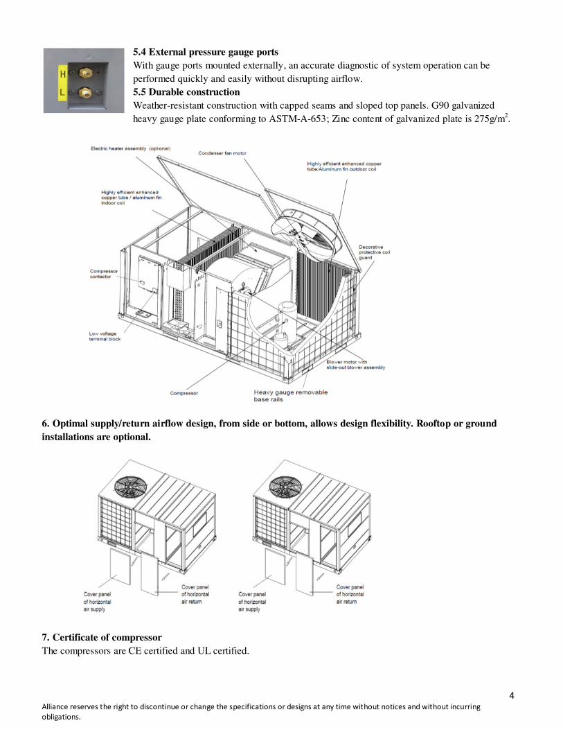
5.4 External pressure gauge ports
With gauge ports mounted externally, an accurate diagnostic of system operation can be
performed quickly and easily without disrupting airflow.
5.5 Durable construction
Weather-resistant construction with capped seams and sloped top panels. G90 galvanized
heavy gauge plate conforming to ASTM-A-653; Zinc content of galvanized plate is 275g/m2.
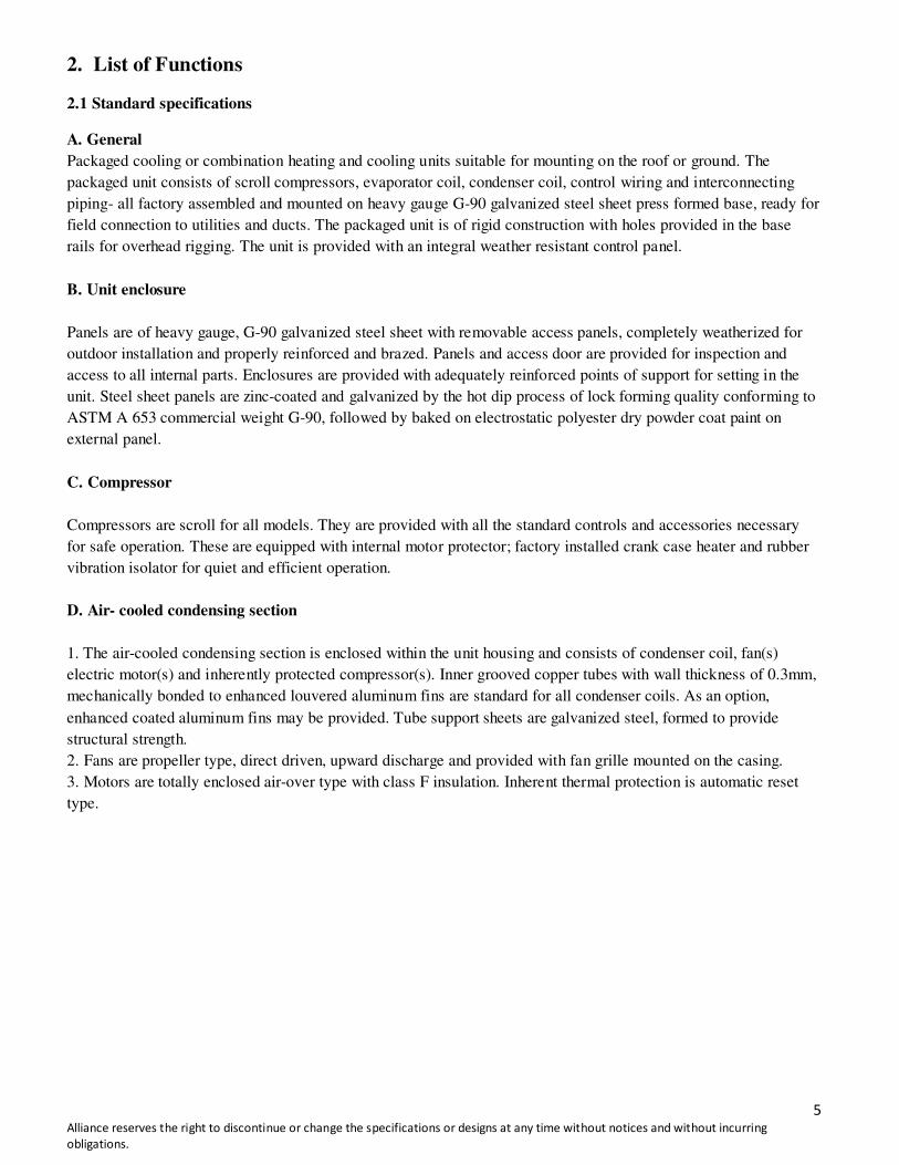
6. Optimal supply/return airflow design, from side or bottom, allows design flexibility. Rooftop or ground
installations are optional.
7. Certificate of compressor
The compressors are CE certified and UL certified.
5 Alliance reserves the right to discontinue or change the specifications or designs at any time without notices and without incurring
obligations.
2. List of Functions
2.1 Standard specifications
A. General
Packaged cooling or combination heating and cooling units suitable for mounting on the roof or ground. The
packaged unit consists of scroll compressors, evaporator coil, condenser coil, control wiring and interconnecting
piping- all factory assembled and mounted on heavy gauge G-90 galvanized steel sheet press formed base, ready for
field connection to utilities and ducts. The packaged unit is of rigid construction with holes provided in the base
rails for overhead rigging. The unit is provided with an integral weather resistant control panel.
B. Unit enclosure
Panels are of heavy gauge, G-90 galvanized steel sheet with removable access panels, completely weatherized for
outdoor installation and properly reinforced and brazed. Panels and access door are provided for inspection and
access to all internal parts. Enclosures are provided with adequately reinforced points of support for setting in the
unit. Steel sheet panels are zinc-coated and galvanized by the hot dip process of lock forming quality conforming to
ASTM A 653 commercial weight G-90, followed by baked on electrostatic polyester dry powder coat paint on
external panel.
C. Compressor
Compressors are scroll for all models. They are provided with all the standard controls and accessories necessary
for safe operation. These are equipped with internal motor protector; factory installed crank case heater and rubber
vibration isolator for quiet and efficient operation.
D. Air- cooled condensing section
1. The air-cooled condensing section is enclosed within the unit housing and consists of condenser coil, fan(s)
electric motor(s) and inherently protected compressor(s). Inner grooved copper tubes with wall thickness of 0.3mm,
mechanically bonded to enhanced louvered aluminum fins are standard for all condenser coils. As an option,
enhanced coated aluminum fins may be provided. Tube support sheets are galvanized steel, formed to provide
structural strength.
2. Fans are propeller type, direct driven, upward discharge and provided with fan grille mounted on the casing.
3. Motors are totally enclosed air-over type with class F insulation. Inherent thermal protection is automatic reset
type.
6 Alliance reserves the right to discontinue or change the specifications or designs at any time without notices and without incurring
obligations.
E. Evaporator coil section
1. All cooling coils are of enhanced louvered fins and inner grooved copper tubes with wall thickness of 0.3mm,
mechanically bonded to aluminum fins. As option, enhanced coated aluminum fins may be provided. Tube support
sheets are galvanized steel, formed to provide structural strength.
2. Drainage pan: An insulated drainage pan made of G-90 galvanized steel is provided, for additional corrosion
protection.
3. Insulation: Insulation is supplied in adequate density and thickness for all units to prevent condensation from
forming on the unit casing. Insulation meets the requirements of NFPA 90A and is protected against deterioration
and erosion from air currents.
F. Evaporator fan
Evaporator fan is of centrifugal forward-curved blade design capable of handling total required CFM and static
pressure in the low and the medium ranges. Casings are made of galvanized steel. Blower motors are of open drip
proof type (totally enclosed types are optional) and conform to NEMA MG-1 and MG-2.
Blower motor is mounted on adjustable base and secured by locking device. Pillow block bearing are selected for
200 000 hours average life at design operating conditions. Shaft is turned, ground and polished from solid steel.
Fans and pulleys are keyed to shaft and designed for continuous operation at maximum motor horsepower and fan
speed. All rotating components and assemblies are statically and dynamically balanced, and every unit is vibration
tested before shipment from the factory.
G. Electronic thermostats
General information: A dedicated electronic thermostat is supplied with unit controls as standard. This thermostat
controls one or two stage heating and cooling applications. The thermostat normally displays room temperature and
mode of operation.
The temperature can be set by up/down buttons for both cooling and heating cycles. The thermostat also allows you
to select continuous fan operation, or have the fan on intermittent operation with the equipment. It also displays the
status of unit, thus providing maximum information for the end user.
2.2 Electric auxiliary heater
Electric auxiliary heaters are the resistance open coil type and conform to the requirements of UL 573 or equivalent.
Electrical characteristics, kW capacities and number of stages are as indicated. Airflow switches, fusible links and
overheat limit thermostats are provided to shut-off power in case of airflow failure/overheating. Electric heater kit is
installed as an externally mounted kit at the supply opening.

7 Alliance reserves the right to discontinue or change the specifications or designs at any time without notices and without incurring
obligations.
2.3 Standard features/options/accessories
Description Standard
features
Option
(Factory installed)
Accessory
(field installed)
Horizontal discharge
Compressor crankcase heaters
Evaporator fan-belt driven
Evaporator fan motor-ODP type(TEFC type
optional)
Condenser fan-direct drive, propeller
type(Except 5ton)
Condenser fan-direct drive, axial type(Only
5ton)
Condenser fan motor-totally enclosed air-over
type
Electric auxiliary heater
Filter, Nylon(Thickness 10&12.5mm, except
5ton)
Filter, aluminum (Thickness 25mm)
Compressor overload protection
Low & high pressure switch
Cooling & heating thermostat
Condenser fan guard
Condenser coil guard
Wired controller KJR-12B
Wired controller KJR-23B
Wired controller KJR-25B
Drainage pipe
Drainage outlet
Snap ring
8 Alliance reserves the right to discontinue or change the specifications or designs at any time without notices and without incurring
obligations.
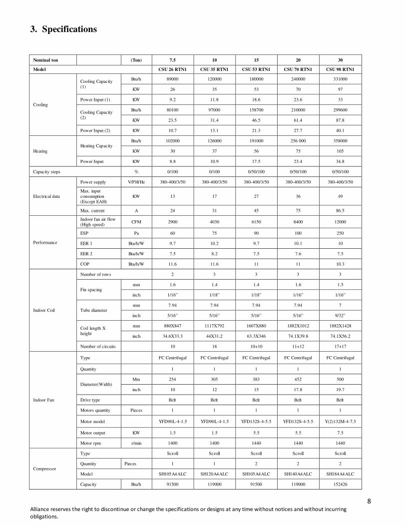
3. Specifications
Nominal ton (Ton) 7.5 10 15 20 30
Model CSU 26 RTN1 CSU 35 RTN1 CSU 53 RTN1 CSU 70 RTN1 CSU 98 RTN1
Cooling
Cooling Capacity
(1)
Btu/h 89000 120000 180000 240000 331000
KW 26 35 53 70 97
Power Input (1) KW 9.2 11.8 18.6 23.6 33
Cooling Capacity
(2)
Btu/h 80100 97000 158700 210000 299600
KW 23.5 31.4 46.5 61.4 87.8
Power Input (2) KW 10.7 13.1 21.3 27.7 40.1
Heating
Heating Capacity Btu/h 102000 126000 191000 256 000 358000
KW 30 37 56 75 105
Power Input KW 8.8 10.9 17.5 23.4 34.8
Capacity steps % 0/100 0/100 0/50/100 0/50/100 0/50/100
Electrical data
Power supply V/PH/Hz 380-400/3/50 380-400/3/50 380-400/3/50 380-400/3/50 380-400/3/50
Max. input
consumption
(Except EAH)
KW 13 17 27 36 49
Max. current A 24 31 45 75 86.5
Performance
Indoor fan air flow
(High speed) CFM 2900 4030 6150 8400 12000
ESP Pa 60 75 90 100 250
EER 1 Btu/h/W 9.7 10.2 9.7 10.1 10
EER 2 Btu/h/W 7.5 8.2 7.5 7.6 7.5
COP Btu/h/W 11.6 11.6 11 11 10.3
Indoor Coil
Number of rows 2 3 3 3 3
Fin spacing mm 1.6 1.4 1.4 1.6 1.5
inch 1/16” 1/18” 1/18” 1/16” 1/16”
Tube diameter mm 7.94 7.94 7.94 7.94 7
inch 5/16” 5/16” 5/16” 5/16” 9/32”
Coil length X
height
mm 880X847 1117X792 1607X880 1882X1012 1882X1428
inch 34.6X33.3 44X31.2 63.3X346 74.1X39.8 74.1X56.2
Number of circuits 10 18 10+10 11+12 17+17
Indoor Fan
Type FC Centrifugal FC Centrifugal FC Centrifugal FC Centrifugal FC Centrifugal
Quantity 1 1 1 1 1
Diameter(Width) Mm 254 305 383 452 500
inch 10 12 15 17.8 19.7
Drive type Belt Belt Belt Belt Belt
Motors quantity Pieces 1 1 1 1 1
Motor model YFD90L-4-1.5 YFD90L-4-1.5 YFD132S-4-5.5 YFD132S-4-5.5 Y(2)132M-4-7.5
Motor output KW 1.5 1.5 5.5 5.5 7.5
Motor rpm r/min 1400 1400 1440 1440 1440
Compressor
Type Scroll Scroll Scroll Scroll Scroll
Quantity Pieces 1 1 2 2 2
Model SH105A4ALC SH120A4ALC SH105A4ALC SH140A4ALC SH184A4ALC
Capacity Btu/h 91500 119000 91500 119000 152426
9 Alliance reserves the right to discontinue or change the specifications or designs at any time without notices and without incurring
obligations.
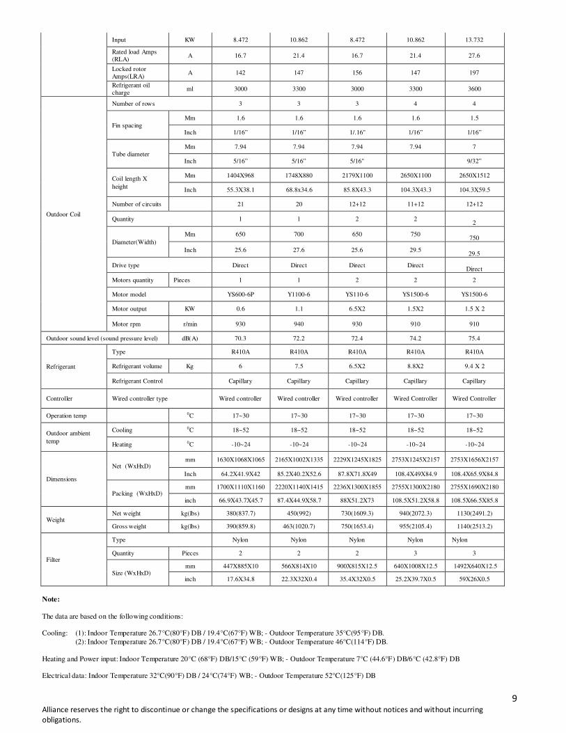
Input KW 8.472 10.862 8.472 10.862 13.732
Rated load Amps
(RLA) A 16.7 21.4 16.7 21.4 27.6
Locked rotor
Amps(LRA) A 142 147 156 147 197
Refrigerant oil
charge ml 3000 3300 3000 3300 3600
Outdoor Coil
Number of rows 3 3 3 4 4
Fin spacing
Mm 1.6 1.6 1.6 1.6 1.5
Inch 1/16” 1/16” 1/.16" 1/16” 1/16”
Tube diameter
Mm 7.94 7.94 7.94 7.94 7
Inch 5/16” 5/16” 5/16" 9/32”
Coil length X
height
Mm 1404X968 1748X880 2179X1100 2650X1100 2650X1512
Inch 55.3X38.1 68.8x34.6 85.8X43.3 104.3X43.3 104.3X59.5
Number of circuits 21 20 12+12 11+12 12+12
Quantity 1 1 2 2
2
Diameter(Width)
Mm 650 700 650 750
750
Inch 25.6 27.6 25.6 29.5
29.5
Drive type Direct Direct Direct Direct
Direct
Motors quantity Pieces 1 1 2 2 2
Motor model YS600-6P Y1100-6 YS110-6 YS1500-6 YS1500-6
Motor output KW 0.6 1.1 6.5X2 1.5X2 1.5 X 2
Motor rpm r/min 930 940 930 910 910
Outdoor sound level (sound pressure level) dB(A) 70.3 72.2 72.4 74.2 75.4
Refrigerant
Type R410A R410A R410A R410A R410A
Refrigerant volume Kg 6 7.5 6.5X2 8.8X2 9.4 X 2
Refrigerant Control Capillary Capillary Capillary Capillary Capillary
Controller Wired controller type Wired controller Wired controller Wired controller Wired Controller Wired Controller
Operation temp 0C 17~30 17~30 17~30 17~30 17~30
Outdoor ambient
temp
Cooling 0C 18~52 18~52 18~52 18~52 18~52
Heating 0C -10~24 -10~24 -10~24 -10~24 -10~24
Dimensions
Net (WxHxD) mm 1630X1068X1065 2165X1002X1335 2229X1245X1825 2753X1245X2157 2753X1656X2157
Inch 64.2X41.9X42 85.2X40.2X52.6 87.8X71.8X49 108.4X49X84.9 108.4X65.9X84.8
Packing (WxHxD) mm 1700X1110X1160 2220X1140X1415 2236X1300X1855 2755X1300X2180 2755X1690X2180
inch 66.9X43.7X45.7 87.4X44.9X58.7 88X51.2X73 108.5X51.2X58.8 108.5X66.5X85.8
Weight Net weight kg(lbs) 380(837.7) 450(992) 730(1609.3) 940(2072.3) 1130(2491.2)
Gross weight kg(lbs) 390(859.8) 463(1020.7) 750(1653.4) 955(2105.4) 1140(2513.2)
Filter
Type Nylon Nylon Nylon Nylon Nylon
Quantity Pieces 2 2 2 3 3
Size (WxHxD) mm 447X885X10 566X814X10 900X815X12.5 640X1008X12.5 1492X640X12.5
inch 17.6X34.8 22.3X32X0.4 35.4X32X0.5 25.2X39.7X0.5 59X26X0.5
Note:
The data are based on the following conditions: Cooling: (1): Indoor Temperature 26.7°C(80°F) DB / 19.4°C(67°F) WB; - Outdoor Temperature 35°C(95°F) DB.
(2): Indoor Temperature 26.7°C(80°F) DB / 19.4°C(67°F) WB; - Outdoor Temperature 46°C(114°F) DB.
Heating and Power input: Indoor Temperature 20°C (68°F) DB/15°C (59°F) WB; - Outdoor Temperature 7°C (44.6°F) DB/6°C (42.8°F) DB Electrical data: Indoor Temperature 32°C(90°F) DB / 24°C(74°F) WB; - Outdoor Temperature 52°C(125°F) DB
10 Alliance reserves the right to discontinue or change the specifications or designs at any time without notices and without incurring
obligations.
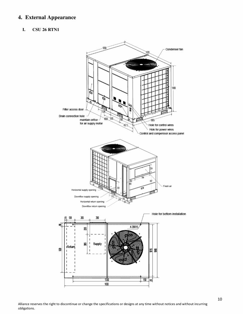
4. External Appearance
I. CSU 26 RTN1
11 Alliance reserves the right to discontinue or change the specifications or designs at any time without notices and without incurring
obligations.
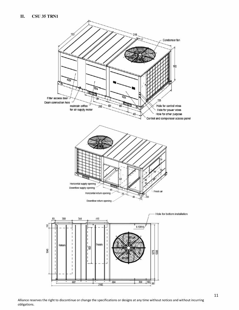
II. CSU 35 TRN1

12 Alliance reserves the right to discontinue or change the specifications or designs at any time without notices and without incurring
obligations.
III. CSU 53 RTN1
13 Alliance reserves the right to discontinue or change the specifications or designs at any time without notices and without incurring
obligations.
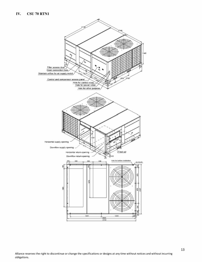
IV. CSU 70 RTN1
14 Alliance reserves the right to discontinue or change the specifications or designs at any time without notices and without incurring
obligations.
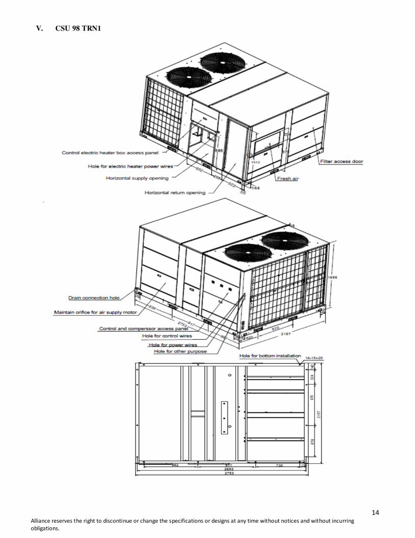
V. CSU 98 TRN1
15 Alliance reserves the right to discontinue or change the specifications or designs at any time without notices and without incurring obligations.
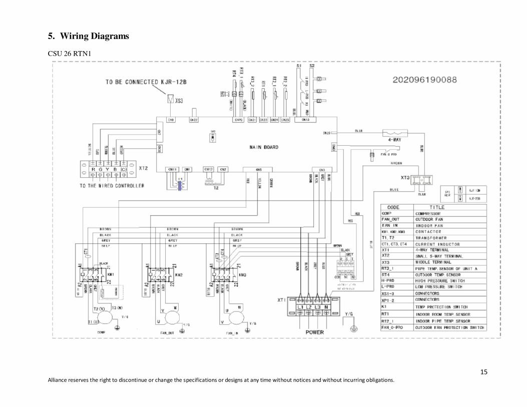
5. Wiring Diagrams
CSU 26 RTN1
16 Alliance reserves the right to discontinue or change the specifications or designs at any time without notices and without incurring obligations.
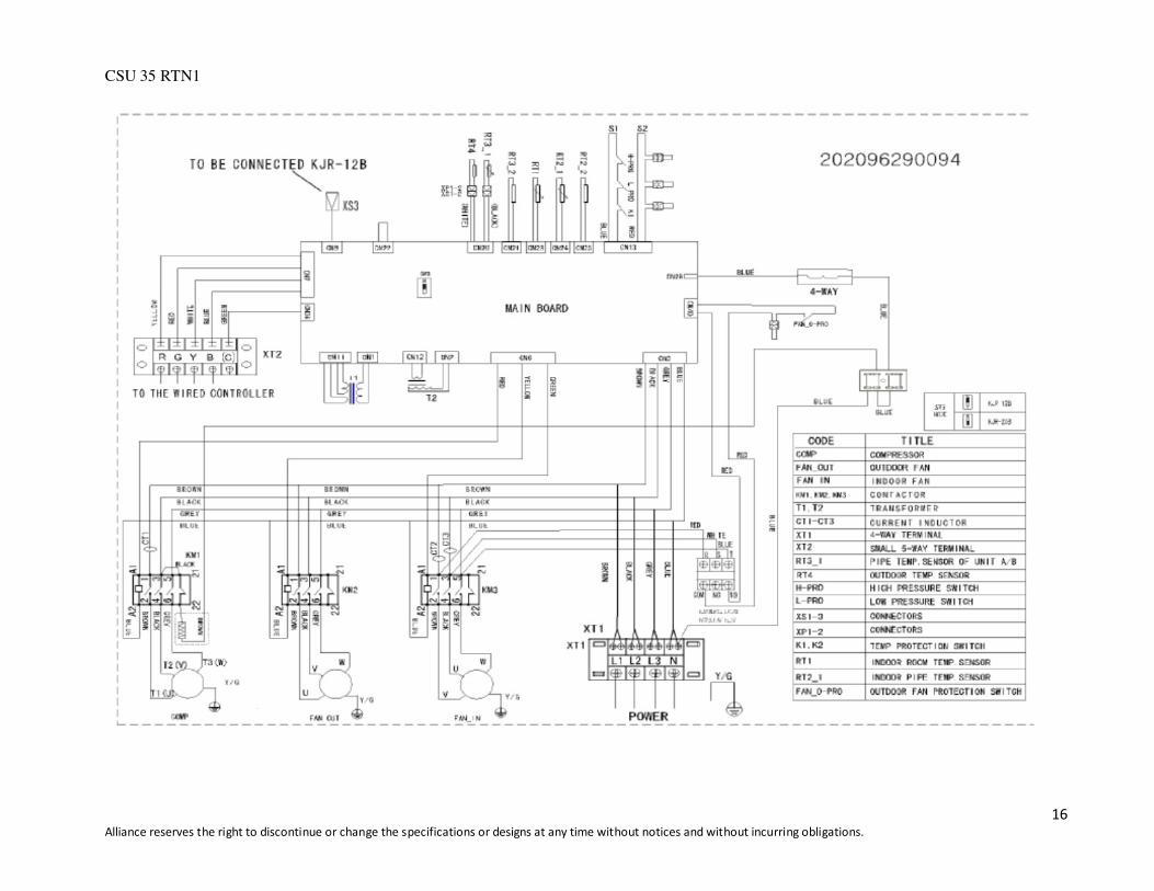
CSU 35 RTN1
17 Alliance reserves the right to discontinue or change the specifications or designs at any time without notices and without incurring obligations.
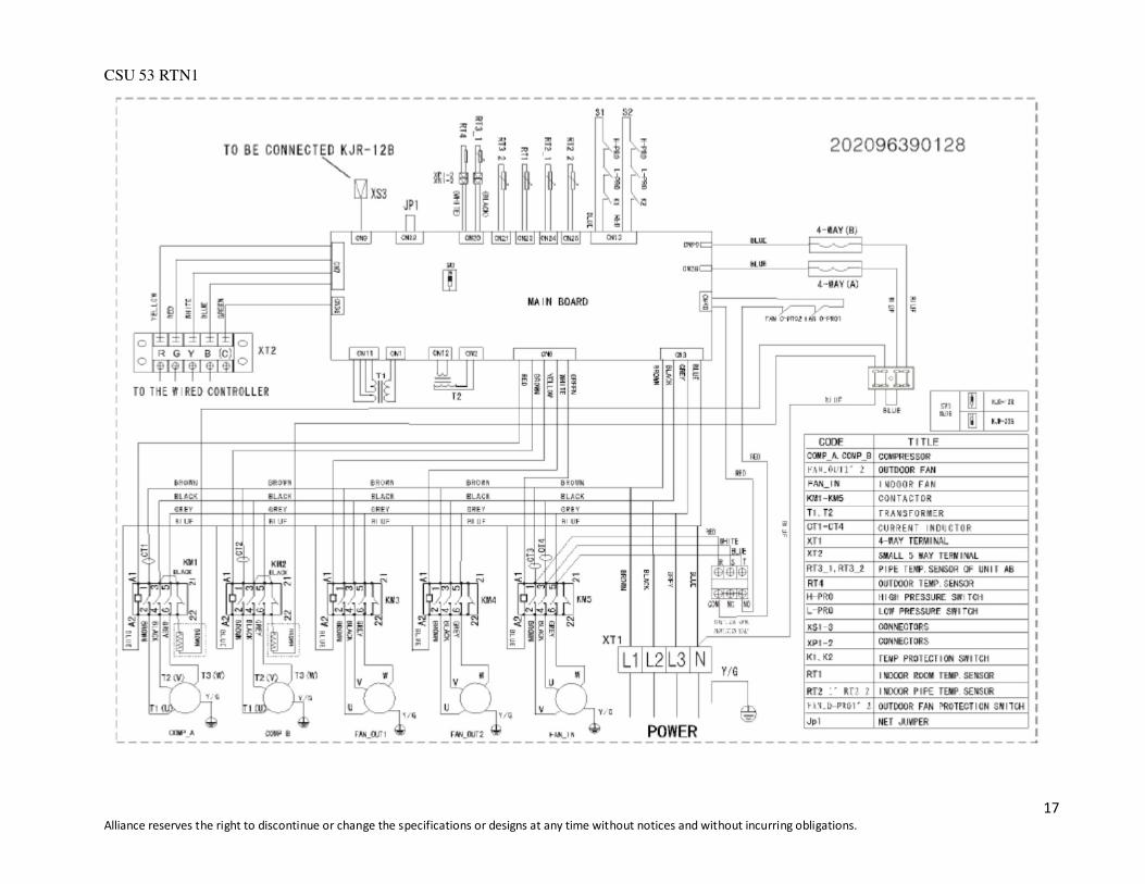
CSU 53 RTN1
18 Alliance reserves the right to discontinue or change the specifications or designs at any time without notices and without incurring obligations.
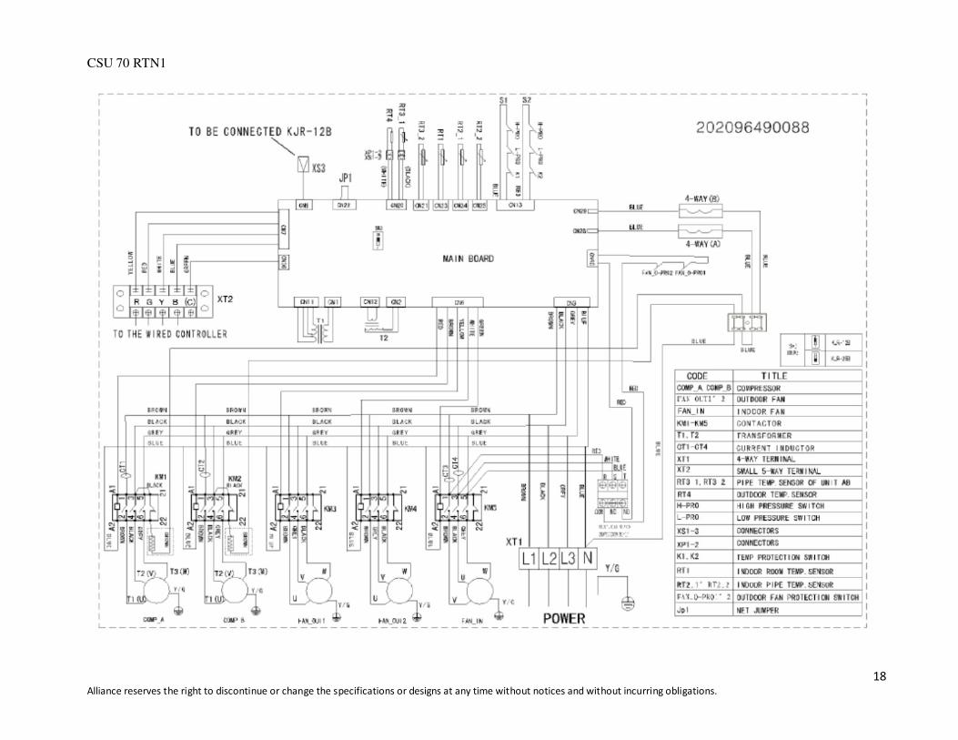
CSU 70 RTN1

19 Alliance reserves the right to discontinue or change the specifications or designs at any time without notices and without incurring obligations.
CSU 98 RTN1

20 Alliance reserves the right to discontinue or change the specifications or designs at any time without notices and without incurring obligations.
6. Performance Data
6.1 Cooling capacity for CSU 26 RTN1:
Air Flow CFM 2800 3000 3200
Ent DB (OF) 75 80 85 90 75 80 85 90 75 80 85 90
Am
bie
nt T
empera
ture
(OF
)
85
Ente
ring W
et B
ulb
(0F
) 61
TGC 82.5 84.2 85.8 87.5 87.3 89 90.8 92.6 89.3 91.1 92.9 94.8
SHC 72.7 80.4 85.3 87.5 77.4 84.3 88.2 91.1 82 84.5 87.9 92.3
67 TGC 94.8 96.7 98.6 100.6 95.9 97.8 99.8 101.8 96.7 98.6 100.6 102.6
SHC 55.6 68.8 81.8 94.3 58 72.6 85.4 96.3 59.5 73.8 83.2 100.1
73 TGC 98.6 100.6 102.6 104.6 99.2 101.2 103.2 105.2 99.4 101.4 103.4 105.5
SHC 36.8 51 62 72.4 37.3 50.7 62.3 75.1 37.8 54.8 63.3 75.4
95
61 TGC 78.6 80.2 81.8 83.4 81 82.6 84.3 86 83.3 85 86.7 88.4
SHC 69.6 75.6 78 81.4 72.3 78.6 81.2 85.3 75.2 79.3 83.5 86.7
67 TGC 85.6 87.3 89.1 90.8 87.1 89 96.6 98 91.4 96.2 98.1 99.8
SHC 53.9 67.7 81.6 86.2 56.3 71.6 86.5 91.3 58.7 75 90.8 92
73 TGC 97.8 99.8 101.8 103.8 98.3 100.3 102.3 104.3 98.7 100.7 102.7 104.7
SHC 35.7 50.2 62.3 74.5 36.2 51.2 64.1 77.3 36.8 52 65.6 79.2
105
61 TGC 72.1 73.5 75 76.5 74.4 75.9 77.4 79 76.5 78 79.6 81.2
SHC 66.4 68.3 71.3 73.2 71.2 72.4 76.3 78.4 75.3 76.5 77.9 80.4
67 TGC 84.4 86.1 87.8 89.6 86.3 88 89.8 91.6 87.8 89.6 91.3 93.2
SHC 51 65 79.2 86.3 53.7 66.2 85 90.3 56.3 73.3 90.6 92.3
73 TGC 95.3 97.2 99.2 101.1 95.2 97.1 99 101 96.7 98.6 100.6 102.6
SHC 34.2 48.9 64.2 76.8 34.1 50.4 65.6 78.8 35.4 52.2 67.2 80.9
115
61 TGC 65.3 66.6 67.9 69.3 67.2 68.5 69.9 71.3 69.8 71.2 72.6 74.1
SHC 63.2 64.6 66.4 68.6 61.2 64.3 67.6 69.1 67.3 69.1 71 73.2
67 TGC 76.7 78.2 79.8 81.4 78.5 80.1 81.7 83.3 80.1 817 83.3 85
SHC 47.8 62.1 75.4 80.2 50.5 66 78.3 82.1 53.1 70.2 82.1 84.6
73 TGC 90.8 92.6 94.5 96.4 86 87.7 89.5 91.3 92.9 94.8 96.7 98.6
SHC 32.4 46.3 61.2 76.4 33 48.4 63.5 78.1 33.7 50.4 66.6 82.3
125
61 TGC 59.9 61.1 62.3 63.6 61.7 62.9 64.1 65.4 64 65.3 66.6 68
SHC 58 59.3 60.9 62.9 56.1 59 62 63.4 61.7 63.4 65.1 67.2
67 TGC 70.4 71.8 73.2 74.7 72 73.5 74.9 76.4 73.5 75 76.5 78
SHC 43.9 57 69.2 73.6 46.3 60.6 71.8 75.3 48.7 64.4 75.3 77.6
73 TGC 83.3 85 86.7 88.4 78.9 80.5 82.1 83.7 85.2 86.9 88.7 90.4
SHC 29.7 42.5 56.1 70.1 30.3 44.4 58.3 71.7 30.9 46.2 61.1 75.5
Notes: 1. All capacities are gross and have not considered indoor fan heat. To obtain NET cooling capacity subtract indoor fan heat.
2. TGC=Total Gross Capacity. (Unit: MBtu/h).
3. SHC=Sensible Heat Capacity. (Unit: MBtu/h).

21 Alliance reserves the right to discontinue or change the specifications or designs at any time without notices and without incurring obligations.
Heating capacity for CSU 26 RTN1:
Net Capacities(kW)-3000 CFM
Outdoor Temp(°F)
70% RH
Peak Net Heating(kW) at indicated Dry Bulb(oF) Peak Total Power(kW) at Indicated Dry Bulb(
oF)
59 68 75.2 80.6 59 68 75.2 80.8
5 14.9 14.0 13.7 13.4 6.9 7.6 8.0 8.5
10.4 16.0 15.3 15.0 14.9 7.1 7.7 8.1 8.6
15.8 17.0 16.5 16.4 16.4 7.1 7.8 8.2 8.8
21.2 17.8 17.3 17.1 16.9 7.2 7.9 8.3 8.9
26.6 18.8 18.5 18.4 18.1 7.3 8.0 8.5 9.1
32 20.3 20.0 19.7 19.4 7.4 8.1 8.6 9.2
37.4 23.3 23.1 22.7 22.4 7.5 8.3 8.8 9.3
44.6 30.3 30 29.6 29.2 7.8 8.8 9.1 9.6
48.2 30.5 30.2 29.9 29.6 8.1 9.0 9.5 10.1
53.6 32.4 33.5 33.4 33.1 8.4 9.4 9.9 10.5
59 35.0 34.4 34.2 33.8 8.6 9.6 10.1 10.7
64.4 37.1 36.4 36.0 35.7 8.9 9.8 10.4 11.0
69.8 39.8 38.9 38.4 37.9 9.0 10.0 10.5 11.0
75.2 42.0 40.9 40.2 39.8 9.2 10.1 10.9 11.3
Notes: 1. For other airflows, see heating capacity correction factor tables.
2. Heating capacities and power are integrated to include the effects of defrost in the frost region.
22 Alliance reserves the right to discontinue or change the specifications or designs at any time without notices and without incurring obligations.
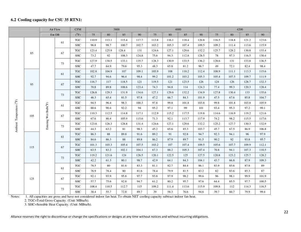
6.2 Cooling capacity for CSU 35 RTN1:
Air Flow CFM 3800 4000 4200
Ent DB (OF) 75 80 85 90 75 80 85 90 75 80 85 90
Am
bie
nt T
empera
ture
(OF
)
85
Ente
ring W
et B
ulb
(0F
)
61 TGC 110.9 113.1 115.4 117.7 113.8 116.1 118.4 120.8 116.5 118.8 121.2 123.6
SHC 96.8 98.7 100.7 102.7 103.2 105.3 107.4 109.5 109.2 111.4 113.6 115.9
67 TGC 123.4 125.9 128.4 131 124.6 127.1 129.6 132.2 125.7 128.2 130.8 133.4
SHC 73.2 92 108.3 124.8 75.6 94.3 112.8 128.5 78 97.3 116.5 130.4
73 TGC 127.9 130.5 133.1 135.7 128.3 130.9 133.5 136.2 128.6 131 133.8 136.5
SHC 47.7 64.9 79.6 95.3 48.3 65.8 81.2 96.7 49 72.1 82.4 98.4
95
61 TGC 102.8 104.9 107 109.1 105.9 108 110.2 112.4 108.9 111.1 113.3 115.6
SHC 92.7 94.6 96.4 98.4 99.2 101.2 103.2 105.3 105.4 107.5 109.7 111.9
67 TGC 116.7 117 118.5 121 119.5 121 123.5 126 124 126 128.7 132.3
SHC 70.8 89.8 108.6 123.4 74.3 94.8 114 124.3 77.4 99.3 120.3 128.4
73 TGC 126.8 129.3 131.9 134.6 127.1 129.6 132.2 134.9 127.8 130.4 133 135.6
SHC 46.3 65.4 81.5 97.8 47.2 66.7 84.3 101.9 47.5 67.6 85.8 104.7
105
61 TGC 94.5 96.4 98.3 100.3 97.8 99.8 101.8 103.8 99.8 101.8 103.8 105.9
SHC 88.6 90.4 92.2 94 95.2 97.1 99 101 93.4 95.3 97.2 99.1
67 TGC 110.3 112.5 114.8 117.1 112.9 115.2 117.5 119.8 114.6 116.9 119.2 121.6
SHC 67.6 86.4 105.9 115.6 71.3 92.1 113.7 117.9 74.2 98.2 115.5 117.6
73 TGC 123.8 126.3 128.8 131.4 124.6 127.1 129.6 132.2 125.2 127.7 130.3 132.9
SHC 44.3 63.2 81 98.3 45.2 65.6 85.3 103.7 45.7 67.5 86.9 106.8
115
61 TGC 86.3 88 89.8 91.6 89.2 91 92.8 94.7 92.3 94.1 96 97.9
SHC 84.6 86.3 88 89.8 86.2 87.9 89.7 91.5 90.2 92 93.8 95.7
67 TGC 101.3 103.3 105.4 107.5 103.2 107 107.4 109.5 105.6 107.7 109.9 112.1
SHC 63.5 83.2 102.1 104.1 67.3 88.2 105.3 107.4 70.8 94.1 107.3 110.5
73 TGC 119.2 121.6 124 126.5 120.1 122.5 125 127.5 120.8 123.2 125.7 128.2
SHC 42.2 61.3 80.1 98.7 42.9 64.1 84.3 104.1 43.7 66.8 87.9 109.3
125
61 TGC 78.5 80 81.6 83.3 81.1 82.7 84.4 86.1 83.9 85.6 87.8 89
SHC 76.9 78.4 80 81.6 78.4 79.9 81.5 83.2 82 83.6 85.3 87
67 TGC 92.1 93.9 95.8 97.7 93.8 97.9 98.2 99.6 96 98.1 99.9 101.9
SHC 57.7 75.6 92.8 94.7 61.2 80.2 95.7 97.6 64.4 85.5 97.7 100.5
73 TGC 108.4 110.5 112.7 115 109.2 111.4 113.6 115.9 109.8 112 114.3 116.5
SHC 38.4 55.7 72.8 89.7 39 58.3 76.6 94.6 39.7 60.7 79.9 99.4
Notes: 1. All capacities are gross and have not considered indoor fan heat. To obtain NET cooling capacity subtract indoor fan heat.
2. TGC=Total Gross Capacity. (Unit: MBtu/h).
3. SHC=Sensible Heat Capacity. (Unit: MBtu/h).
23 Alliance reserves the right to discontinue or change the specifications or designs at any time without notices and without incurring obligations.
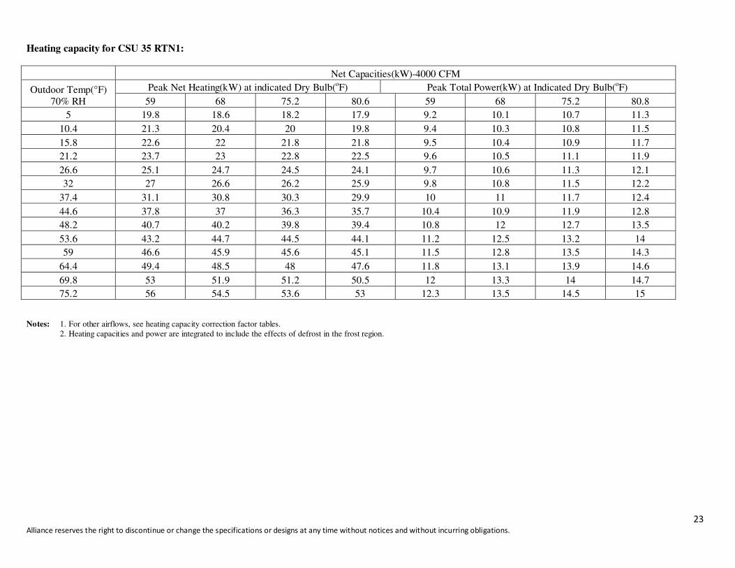
Heating capacity for CSU 35 RTN1:
Net Capacities(kW)-4000 CFM
Outdoor Temp(°F)
70% RH
Peak Net Heating(kW) at indicated Dry Bulb(oF) Peak Total Power(kW) at Indicated Dry Bulb(
oF)
59 68 75.2 80.6 59 68 75.2 80.8
5 19.8 18.6 18.2 17.9 9.2 10.1 10.7 11.3
10.4 21.3 20.4 20 19.8 9.4 10.3 10.8 11.5
15.8 22.6 22 21.8 21.8 9.5 10.4 10.9 11.7
21.2 23.7 23 22.8 22.5 9.6 10.5 11.1 11.9
26.6 25.1 24.7 24.5 24.1 9.7 10.6 11.3 12.1
32 27 26.6 26.2 25.9 9.8 10.8 11.5 12.2
37.4 31.1 30.8 30.3 29.9 10 11 11.7 12.4
44.6 37.8 37 36.3 35.7 10.4 10.9 11.9 12.8
48.2 40.7 40.2 39.8 39.4 10.8 12 12.7 13.5
53.6 43.2 44.7 44.5 44.1 11.2 12.5 13.2 14
59 46.6 45.9 45.6 45.1 11.5 12.8 13.5 14.3
64.4 49.4 48.5 48 47.6 11.8 13.1 13.9 14.6
69.8 53 51.9 51.2 50.5 12 13.3 14 14.7
75.2 56 54.5 53.6 53 12.3 13.5 14.5 15
Notes: 1. For other airflows, see heating capacity correction factor tables.
2. Heating capacities and power are integrated to include the effects of defrost in the frost region.

24 Alliance reserves the right to discontinue or change the specifications or designs at any time without notices and without incurring obligations.
6.3 Cooling capacity for CSU 53 RTN1:
Air Flow CFM 5500 6000 6500
Ent DB (OF) 75 80 85 90 75 80 85 90 75 80 85 90
Am
bie
nt T
empera
ture
(OF
)
85
Ente
ring W
et B
ulb
(0F
)
61 TGC 163.6 165.6 172.9 182.7 168 171.6 179 188.7 169.9 174.2 185.1 193.6
SHC 131.5 155.8 166 175.3 138.7 165.6 173.6 183 146.1 167.2 177.7 185.9
67 TGC 183.3 185.5 187.6 190.2 188.7 190 191.1 192.4 191 192.5 193.6 195.1
SHC 104.7 127.8 149.8 172.9 109.3 132.7 157.1 180.2 111.2 136.4 162 187.6
73 TGC 193.6 197.3 199.8 202.2 195.8 198.5 202.2 204.5 198.3 201 203.3 205.8
SHC 72.2 96.8 117 136.4 73.6 99 119.6 138.6 74.9 99.9 121.6 143.7
95
61 TGC 153.4 157.1 164.5 175.4 155.3 162 171.7 181.4 160.8 164.5 176.6 186.3
SHC 125.3 149.8 159.5 170.1 132.7 157.1 166.6 176 140.1 159.5 171.3 180.8
67 TGC 171.7 174.2 176.6 180.2 179 180 182.7 183.9 185.1 186.5 187.7 188.7
SHC 99.9 123 146.1 169.2 104.1 129 153.5 179 108.1 132.8 160.8 186.3
73 TGC 188.8 191.1 193.5 196.1 190.2 192.2 195.2 198.5 191.9 194.3 196.8 198
SHC 69 93.1 114.8 135.2 70.5 96.3 117.8 140.1 71.8 97.9 120.7 143.7
105
61 TGC 142.7 146.4 153.8 166.1 147.6 151.3 163.6 171 150.1 156.2 169.7 180.8
SHC 119.6 140.5 147.6 159.4 127.9 145.2 157 164.1 135.3 151.5 164.6 173.2
67 TGC 163.6 166.1 169.7 171 164.8 168.5 173.4 175.9 173.4 175.9 178.4 180.8
SHC 94.6 118.1 141.3 165.7 109 124.2 149.8 170.6 102.6 130.3 157.1 175.4
73 TGC 185.7 187 188.2 189.4 188.2 189.4 190.7 193.1 190.7 191.9 193.1 194.3
SHC 65.6 89.2 111.7 132.8 67 92.3 115.5 138.9 68.3 95.3 118.6 142.4
115
61 TGC 130.4 135.3 147.6 159.9 134.1 141.5 153.8 166.1 137.8 140.4 150.9 172.2
SHC 114.5 131.2 143.2 155.1 121.6 135.8 147.6 159.4 127.9 136.2 146.9 167
67 TGC 153.8 156.2 157.4 160.9 155 158.7 161.1 163.6 163.6 166.1 169.7 174
SHC 98.4 113.4 136.5 159.9 103.3 119.9 145.1 163.6 108.2 125.5 151.3 168.8
73 TGC 173.4 175.9 178.4 179.6 178.4 180.8 182 183.3 182 183.3 184.5 185.7
SHC 62.1 85.6 108.9 131.6 63.5 89.8 113.2 136.5 66.4 92.3 118.1 143.9
125
61 TGC 125.4 130.1 141.9 152.1 128.9 136 147.8 159.7 132.5 140.7 153.8 165.6
SHC 110.1 126.2 137.7 147.5 117 131.9 143.4 154.9 13 136.5 149.1 160.6
67 TGC 147.8 150.2 151.4 153.8 149 152.6 154.9 157.3 157.3 159.7 163.2 167.1
SHC 94.6 109 131.3 153.8 99.3 115.3 139.6 152.6 104.1 120.6 145.5 162.1
73 TGC 166.8 169.1 171.5 172.7 171.5 173.9 175 176.2 175 176.2 177.4 178.6
SHC 59.7 82.3 104.7 126.5 61 86.3 108.8 131.3 63.9 88.7 113.5 138.4
Notes: 1. All capacities are gross and have not considered indoor fan heat. To obtain NET cooling capacity subtract indoor fan heat.
2. TGC=Total Gross Capacity. (Unit: MBtu/h).
3. SHC=Sensible Heat Capacity. (Unit: MBtu/h).
25 Alliance reserves the right to discontinue or change the specifications or designs at any time without notices and without incurring obligations.
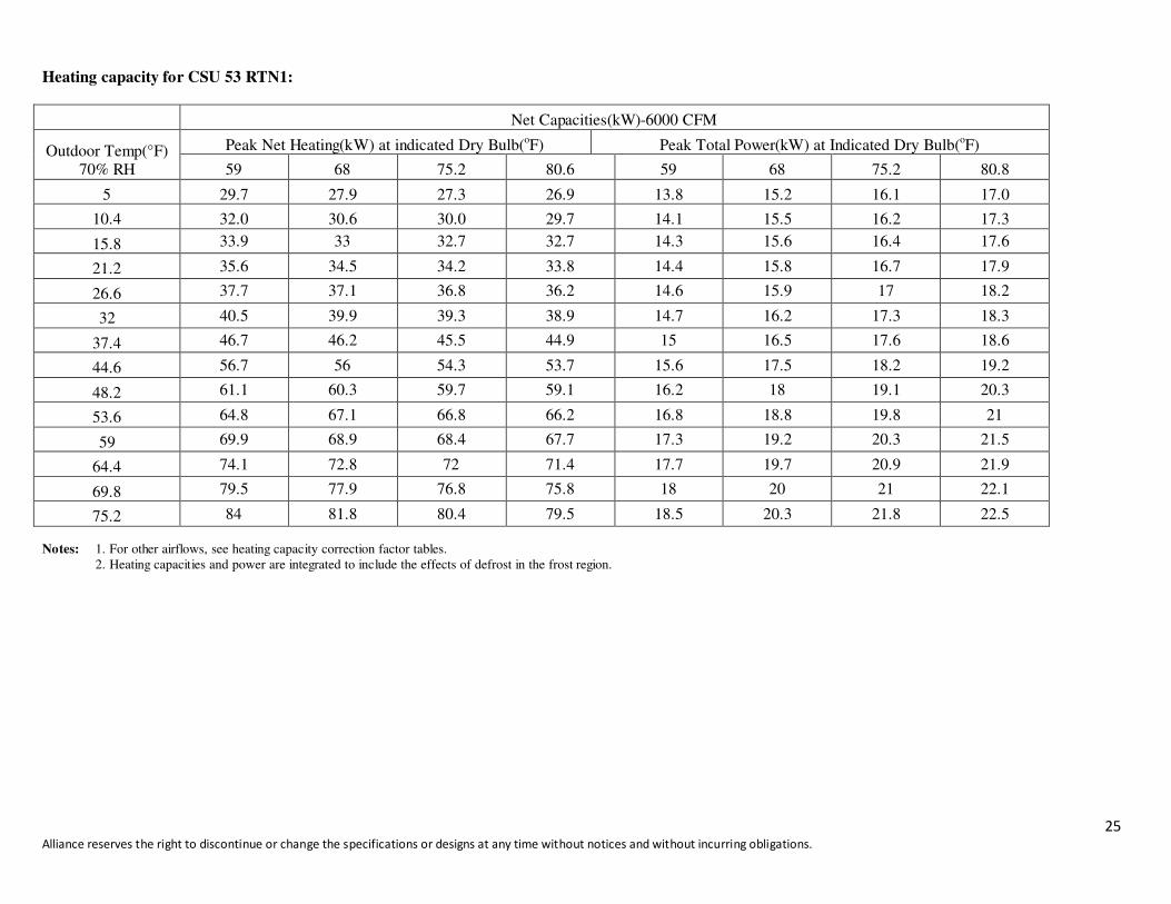
Heating capacity for CSU 53 RTN1:
Net Capacities(kW)-6000 CFM
Outdoor Temp(°F)
70% RH
Peak Net Heating(kW) at indicated Dry Bulb(oF) Peak Total Power(kW) at Indicated Dry Bulb(
oF)
59 68 75.2 80.6 59 68 75.2 80.8
5 29.7 27.9 27.3 26.9 13.8 15.2 16.1 17.0
10.4 32.0 30.6 30.0 29.7 14.1 15.5 16.2 17.3
15.8 33.9 33 32.7 32.7 14.3 15.6 16.4 17.6
21.2 35.6 34.5 34.2 33.8 14.4 15.8 16.7 17.9
26.6 37.7 37.1 36.8 36.2 14.6 15.9 17 18.2
32 40.5 39.9 39.3 38.9 14.7 16.2 17.3 18.3
37.4 46.7 46.2 45.5 44.9 15 16.5 17.6 18.6
44.6 56.7 56 54.3 53.7 15.6 17.5 18.2 19.2
48.2 61.1 60.3 59.7 59.1 16.2 18 19.1 20.3
53.6 64.8 67.1 66.8 66.2 16.8 18.8 19.8 21
59 69.9 68.9 68.4 67.7 17.3 19.2 20.3 21.5
64.4 74.1 72.8 72 71.4 17.7 19.7 20.9 21.9
69.8 79.5 77.9 76.8 75.8 18 20 21 22.1
75.2 84 81.8 80.4 79.5 18.5 20.3 21.8 22.5
Notes: 1. For other airflows, see heating capacity correction factor tables.
2. Heating capacities and power are integrated to include the effects of defrost in the frost region.

26 Alliance reserves the right to discontinue or change the specifications or designs at any time without notices and without incurring obligations.
6.4 Cooling Capacity for CSU 70 RTN1:
Air Flow CFM 7700 8400 9000
Ent DB (OF) 75 80 85 90 75 80 85 90 75 80 85 90
Am
bie
nt T
empera
ture
(OF
)
85
Ente
ring W
et B
ulb
(0F
)
61 TGC 216.1 218.7 228.5 241.3 222 226.7 236.4 249.3 224.4 230.1 244.6 255.8
SHC 173.7 205.9 221.6 234.1 183.3 218.7 229.3 241.8 193.1 223.2 237.2 248.1
67 TGC 242.1 245.1 247.8 251.2 249.3 251.1 252.5 254.2 252.4 254.3 255.8 257.7
SHC 138.3 168.8 197.9 228.5 144.5 175.3 207.5 238.1 146.9 180.2 214 247.8
73 TGC 255.8 260.7 263.9 267.2 258.7 262.3 267.2 270.2 262 265.5 268.6 271.9
SHC 95 127.9 154.5 180.2 97.2 130.8 158 183.1 99 132 160.7 189.8
95
61 TGC 202.6 207.5 217.3 231.7 205.2 214 226.9 239.7 212.4 217.3 233.4 246.2
SHC 165.6 197.9 210.7 224.8 175.3 205.5 217.8 230.1 185.1 210.7 226.3 238.8
67 TGC 226.9 230.1 233.4 238.1 236.4 240 241.3 242.9 244.6 246.4 248 249.3
SHC 132 162.5 193.1 223.6 137.5 170.5 202.8 236.4 142.8 185.5 212.4 246.2
73 TGC 249.4 252.5 255.6 259 251.3 254 257.9 262.3 253.5 256.8 260 261.6
SHC 91.2 123 151.6 178.6 93.1 127.2 155.7 185.1 94.9 129.4 159.4 189.8
105
61 TGC 188.5 193.4 203.1 219.4 195 199.9 216.1 225.9 198.3 206.4 224.3 238.9
SHC 158 187.6 197 212.8 169 193.9 209.6 219.1 178.8 200.2 217.5 231.7
67 TGC 216.1 219.4 224.3 225.9 217.8 222.6 229.1 232.4 229.1 232.4 235.6 238.9
SHC 125 156 186.7 218.9 144 164.1 197.9 209.1 135.5 172.1 207.5 238.9
73 TGC 245.4 247 248.6 250.3 248.6 250.3 251.9 255.1 251.9 253.5 255.1 256.8
SHC 86.6 117.8 147.6 175.5 88.6 122 152.6 183.5 90.2 125.9 156.7 188.2
115
61 TGC 172.3 178.8 192 211.3 177.1 186.9 203.1 219.4 182 193.4 211.3 227.5
SHC 151.3 173.4 189.2 204.9 160.7 181.3 197 212.8 169 187.6 204.9 220.7
67 TGC 203.1 206.4 208 211.3 204.8 209.6 212.9 216.1 216.1 219.4 224.3 227.5
SHC 130 149.8 180.4 211.3 136.5 158.4 191.8 216.1 143 165.8 199.9 227.5
73 TGC 229.1 232.4 235.6 237.3 235.6 238.9 240.5 242.1 240.5 242.1 243.8 245.4
SHC 82.1 113.1 143.8 173.9 83.9 118.6 149.5 180.4 8708 121.9 156 190.1
125
61 TGC 162.5 168.6 184 199.3 167.1 176.3 191.6 207 171.6 182.4 199.3 214.6
SHC 147.2 163.6 178.4 193.3 151.6 171 185.9 200.7 159.4 177 193.3 208.2
67 TGC 191.6 194.7 196.2 210.3 193.2 197.8 200.8 203.9 203.9 207 211.6 214.6
SHC 122.6 141.3 170.2 189.3 128.8 149.5 180.9 199.8 134.9 156.4 188.6 210.3
73 TGC 216.2 219.2 222.3 223.8 222.3 225.4 226.9 228.4 226.9 228.4 230 231.5
SHC 77.4 106.7 135.7 164 79.1 111.9 141 170.2 82.8 115 147.2 179.4
Notes: 1. All capacities are gross and have not considered indoor fan heat. To obtain NET cooling capacity subtract indoor fan heat. 2. TGC=Total Gross Capacity. (Unit: MBtu/h).
3. SHC=Sensible Heat Capacity. (Unit: MBtu/h)
27 Alliance reserves the right to discontinue or change the specifications or designs at any time without notices and without incurring obligations.
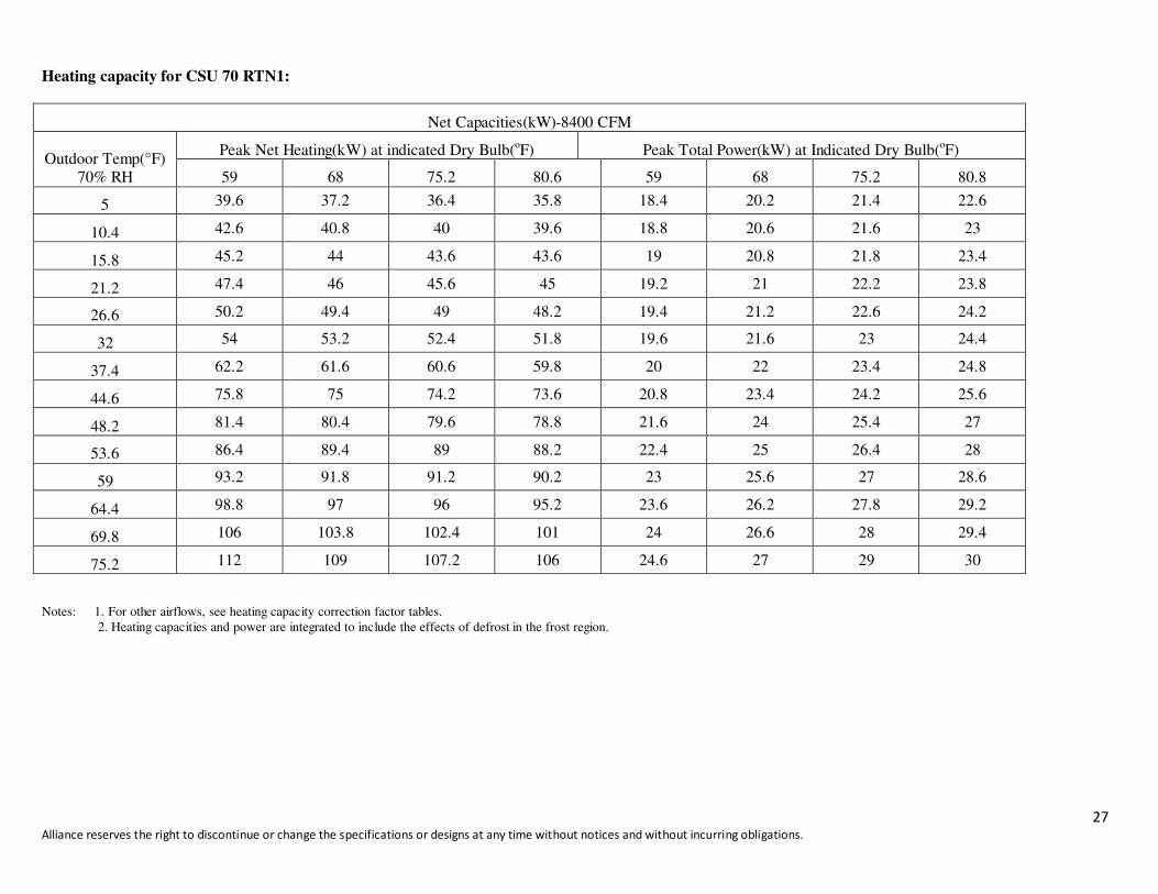
Heating capacity for CSU 70 RTN1:
Net Capacities(kW)-8400 CFM
Outdoor Temp(°F)
70% RH
Peak Net Heating(kW) at indicated Dry Bulb(oF) Peak Total Power(kW) at Indicated Dry Bulb(
oF)
59 68 75.2 80.6 59 68 75.2 80.8
5 39.6 37.2 36.4 35.8 18.4 20.2 21.4 22.6
10.4 42.6 40.8 40 39.6 18.8 20.6 21.6 23
15.8 45.2 44 43.6 43.6 19 20.8 21.8 23.4
21.2 47.4 46 45.6 45 19.2 21 22.2 23.8
26.6 50.2 49.4 49 48.2 19.4 21.2 22.6 24.2
32 54 53.2 52.4 51.8 19.6 21.6 23 24.4
37.4 62.2 61.6 60.6 59.8 20 22 23.4 24.8
44.6 75.8 75 74.2 73.6 20.8 23.4 24.2 25.6
48.2 81.4 80.4 79.6 78.8 21.6 24 25.4 27
53.6 86.4 89.4 89 88.2 22.4 25 26.4 28
59 93.2 91.8 91.2 90.2 23 25.6 27 28.6
64.4 98.8 97 96 95.2 23.6 26.2 27.8 29.2
69.8 106 103.8 102.4 101 24 26.6 28 29.4
75.2 112 109 107.2 106 24.6 27 29 30
Notes: 1. For other airflows, see heating capacity correction factor tables.
2. Heating capacities and power are integrated to include the effects of defrost in the frost region.
28 Alliance reserves the right to discontinue or change the specifications or designs at any time without notices and without incurring obligations.
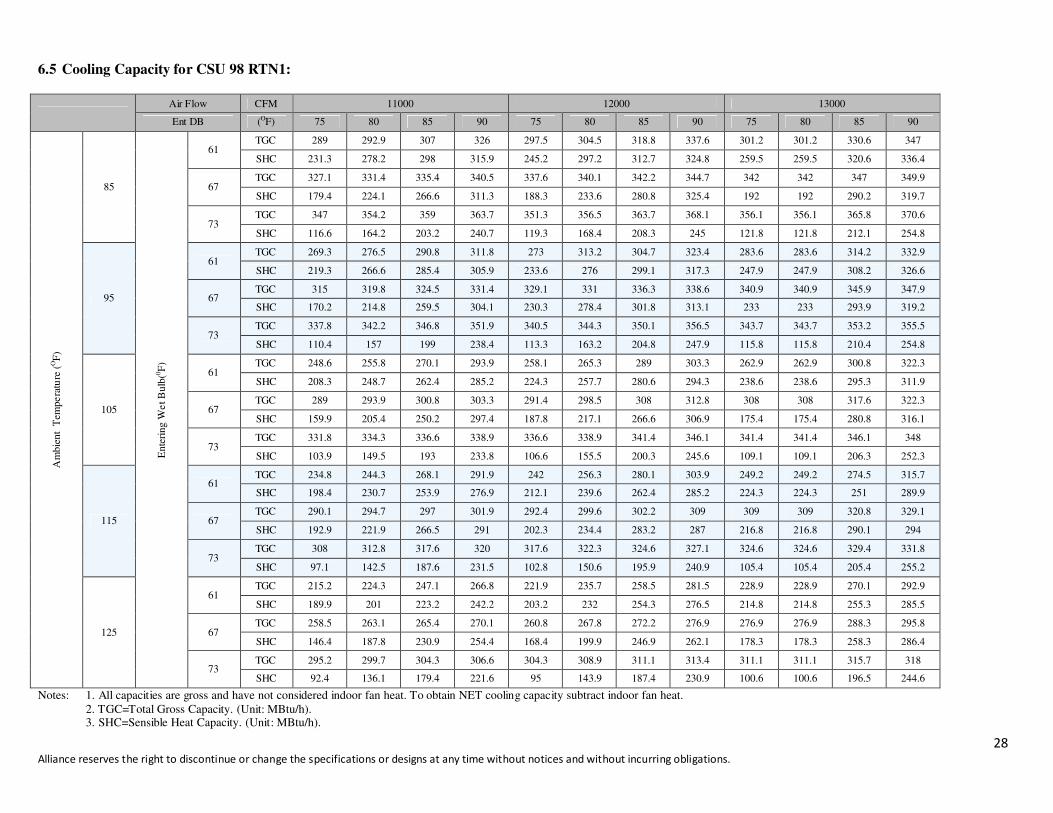
6.5 Cooling Capacity for CSU 98 RTN1:
Air Flow CFM 11000 12000 13000
Ent DB (OF) 75 80 85 90 75 80 85 90 75 80 85 90
Am
bie
nt T
empera
ture
(OF
)
85
Ente
ring W
et B
ulb
(0F
) 61
TGC 289 292.9 307 326 297.5 304.5 318.8 337.6 301.2 301.2 330.6 347
SHC 231.3 278.2 298 315.9 245.2 297.2 312.7 324.8 259.5 259.5 320.6 336.4
67 TGC 327.1 331.4 335.4 340.5 337.6 340.1 342.2 344.7 342 342 347 349.9
SHC 179.4 224.1 266.6 311.3 188.3 233.6 280.8 325.4 192 192 290.2 319.7
73 TGC 347 354.2 359 363.7 351.3 356.5 363.7 368.1 356.1 356.1 365.8 370.6
SHC 116.6 164.2 203.2 240.7 119.3 168.4 208.3 245 121.8 121.8 212.1 254.8
95
61 TGC 269.3 276.5 290.8 311.8 273 313.2 304.7 323.4 283.6 283.6 314.2 332.9
SHC 219.3 266.6 285.4 305.9 233.6 276 299.1 317.3 247.9 247.9 308.2 326.6
67 TGC 315 319.8 324.5 331.4 329.1 331 336.3 338.6 340.9 340.9 345.9 347.9
SHC 170.2 214.8 259.5 304.1 230.3 278.4 301.8 313.1 233 233 293.9 319.2
73 TGC 337.8 342.2 346.8 351.9 340.5 344.3 350.1 356.5 343.7 343.7 353.2 355.5
SHC 110.4 157 199 238.4 113.3 163.2 204.8 247.9 115.8 115.8 210.4 254.8
105
61 TGC 248.6 255.8 270.1 293.9 258.1 265.3 289 303.3 262.9 262.9 300.8 322.3
SHC 208.3 248.7 262.4 285.2 224.3 257.7 280.6 294.3 238.6 238.6 295.3 311.9
67 TGC 289 293.9 300.8 303.3 291.4 298.5 308 312.8 308 308 317.6 322.3
SHC 159.9 205.4 250.2 297.4 187.8 217.1 266.6 306.9 175.4 175.4 280.8 316.1
73 TGC 331.8 334.3 336.6 338.9 336.6 338.9 341.4 346.1 341.4 341.4 346.1 348
SHC 103.9 149.5 193 233.8 106.6 155.5 200.3 245.6 109.1 109.1 206.3 252.3
115
61 TGC 234.8 244.3 268.1 291.9 242 256.3 280.1 303.9 249.2 249.2 274.5 315.7
SHC 198.4 230.7 253.9 276.9 212.1 239.6 262.4 285.2 224.3 224.3 251 289.9
67 TGC 290.1 294.7 297 301.9 292.4 299.6 302.2 309 309 309 320.8 329.1
SHC 192.9 221.9 266.5 291 202.3 234.4 283.2 287 216.8 216.8 290.1 294
73 TGC 308 312.8 317.6 320 317.6 322.3 324.6 327.1 324.6 324.6 329.4 331.8
SHC 97.1 142.5 187.6 231.5 102.8 150.6 195.9 240.9 105.4 105.4 205.4 255.2
125
61 TGC 215.2 224.3 247.1 266.8 221.9 235.7 258.5 281.5 228.9 228.9 270.1 292.9
SHC 189.9 201 223.2 242.2 203.2 232 254.3 276.5 214.8 214.8 255.3 285.5
67 TGC 258.5 263.1 265.4 270.1 260.8 267.8 272.2 276.9 276.9 276.9 288.3 295.8
SHC 146.4 187.8 230.9 254.4 168.4 199.9 246.9 262.1 178.3 178.3 258.3 286.4
73 TGC 295.2 299.7 304.3 306.6 304.3 308.9 311.1 313.4 311.1 311.1 315.7 318
SHC 92.4 136.1 179.4 221.6 95 143.9 187.4 230.9 100.6 100.6 196.5 244.6
Notes: 1. All capacities are gross and have not considered indoor fan heat. To obtain NET cooling capacity subtract indoor fan heat.
2. TGC=Total Gross Capacity. (Unit: MBtu/h). 3. SHC=Sensible Heat Capacity. (Unit: MBtu/h).

29 Alliance reserves the right to discontinue or change the specifications or designs at any time without notices and without incurring obligations.
Heating capacity for CSU 98 RTN1:
Net Capacities(kW)-12000 CFM
Outdoor Temp(°F)
70% RH
Peak Net Heating(kW) at indicated Dry Bulb(oF) Peak Total Power(kW) at Indicated Dry Bulb(
oF)
59 68 75.2 80.6 59 68 75.2 80.8
5 59.4 55.8 54.6 53.8 27.6 30.4 32.2 34
10.4 64 61.2 60 59.4 28.2 31 32.4 34.6
15.8 67.8 66 65.4 65.4 28.6 31.2 32.8 35.2
21.2 71.2 69 68.4 67.6 28.8 31.6 33.4 35.8
26.6 75.4 74.2 73.6 72.4 29.2 31.8 34 36.4
32 81 79.8 78.6 77.8 29.4 32.4 34.6 36.6
37.4 93.4 92.4 91 89.8 30 33 35.2 37.2
44.6 107.4 105 104.8 104.2 31.2 34.8 36.4 38.4
48.2 122.2 120.6 119.4 118.2 32.4 36 38.2 40.6
53.6 129.6 134.2 133.6 132.4 33.6 37.6 39.6 42
59 139.8 137.8 136.8 135.4 34.6 38.4 40.6 43
64.4 148.2 145.6 144 142.8 35.4 39.4 41.8 43.8
69.8 159 155.8 153.6 151.6 36 40 42 44.2
75.2 168 163.6 160.8 159 37 40.6 43.6 45
Notes: 1. For other airflows, see heating capacity correction factor tables.
2. Heating capacities and power are integrated to include the effects of defrost in the frost region.

30 Alliance reserves the right to discontinue or change the specifications or designs at any time without notices and without incurring obligations.
7. Electrical Data
Model Power Supply Compressor Evaporator fan Motor Condenser fan motor
MCA TOCA MFA STC RNC IPT Qty RNC IPT Qty RNC IPT Qty
CSU 26 RTN1 26 32 42 142 16.4 8.47 1 3.7 1.9 1 1.7 0.85 1
CSU 35 RTN1 33 40 55 147 29.5 10.8 1 3.7 1.9 1 2.7 1.3 1
CSU 53 RTN1 56 67 89 110 32.8 16.8 2 9.2 4.65 1 1.7 0.85 2
CSU 70 RTN1 72 85 115 140 42.8 21.6 2 11.8 5.5 1 3.3 1.7 2
CSU 98 RTN1 91 109 146 197 55.2 27.4 2 13 7.0 1 6.5 3.4 2
MCA: Min. Current Amps. (A) TOCA: Total Over-Current Amps. ( A)
MFA: Max Fuse Amps. (A) STC: Starting Current (A)
RNC: Running Current (A) IPT: Input (kW)
Note:
1. The starting current is indicated for each compressor motor.
2. The maximum currents of the compressor can be estimated as follows:
One Compressor unit Two Compressor unit
Max. current (RNC x Max. IPT)/IPT (RNC x Max. IPT)/IPT
Max. instantaneous current STC (STC+RNC x 0.5 x MAX.IPT)/IPT
Max. IPTx: Compressor power input from the performance table at the expected maximum condition
STC, IPT, RNC: Compressor data from the above table
The data in the compressor motor column shall indicate the respective values of the refrigeration cycle.
Voltage imbalance between phases to be less than 2%.
31 Alliance reserves the right to discontinue or change the specifications or designs at any time without notices and without incurring obligations.
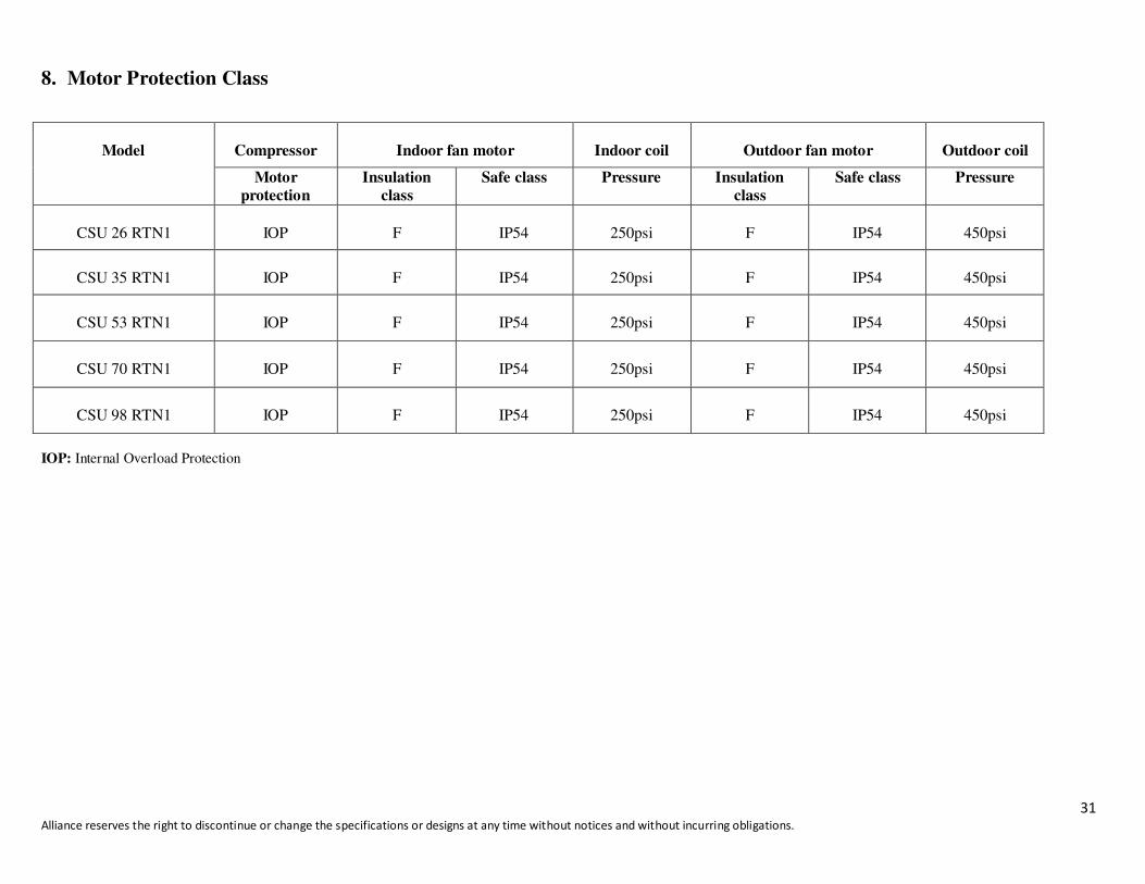
8. Motor Protection Class
Model
Compressor
Indoor fan motor
Indoor coil
Outdoor fan motor
Outdoor coil
Motor
protection
Insulation
class
Safe class Pressure Insulation
class
Safe class Pressure
CSU 26 RTN1
IOP
F
IP54
250psi
F
IP54
450psi
CSU 35 RTN1
IOP
F
IP54
250psi
F
IP54
450psi
CSU 53 RTN1
IOP
F
IP54
250psi
F
IP54
450psi
CSU 70 RTN1
IOP
F
IP54
250psi
F
IP54
450psi
CSU 98 RTN1
IOP
F
IP54
250psi
F
IP54
450psi
IOP: Internal Overload Protection

32 Alliance reserves the right to discontinue or change the specifications or designs at any time without notices and without incurring
obligations.
9. Parameter and Pressure Chart for Air Flow
9.1 Model: CSU 26 TRN1
Parameter table for indoor unit air volume:
Static pressure (Pa) 0 20 50 60 75 100 125 150 175
Air flow (CFM) 3240 3149 2996 2941 2886 2782 2664 2540 2411
Brake power (kW) 1.83 1.78 1.70 1.66 1.63 1.58 1.53 1.47 1.41
Fan speed(rpm) 1260 1265 1268 1271 1274 1277 1281 1285 1287
Curve diagram of static pressure, air flow volume
Parameter table for outdoor unit air volume:
Model Static
(Pa)
Air Flow
(CFM)
Brake Power
(kW)
Fan speed
(rpm)
CSU 26 RTN1
0 5880 0.78 900
10 5647 0.79 889
20 5411 0.80 875
33 Alliance reserves the right to discontinue or change the specifications or designs at any time without notices and without incurring
obligations.
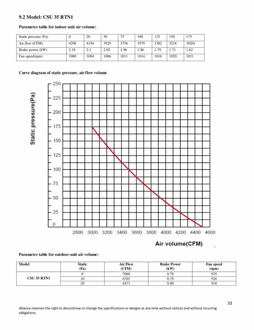
9.2 Model: CSU 35 RTN1
Parameter table for indoor unit air volume:
Static pressure (Pa) 0 20 50 75 100 125 150 175
Air flow (CFM) 4298 4156 3929 3756 3579 3382 3218 30201
Brake power (kW) 2.18 2.1 2.02 1.96 1.86 1.79 1.71 1.62
Fan speed(rpm) 1000 1004 1006 1011 1014 1016 1020 1021
Curve diagram of static pressure, air flow volume
Parameter table for outdoor unit air volume:
Model Static
(Pa)
Air Flow
(CFM)
Brake Power
(kW)
Fan speed
(rpm)
CSU 35 RTN1
0 7060 0.78 935
10 6765 0.79 926
20 6471 0.80 918
34 Alliance reserves the right to discontinue or change the specifications or designs at any time without notices and without incurring
obligations.
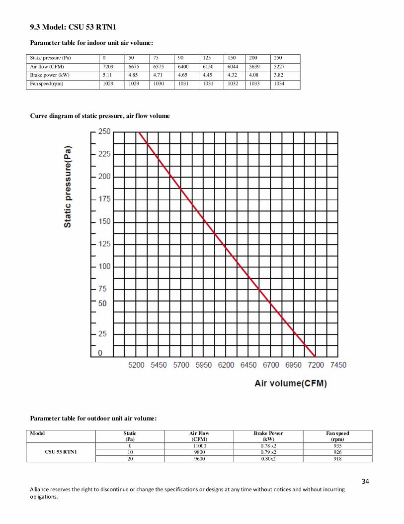
9.3 Model: CSU 53 RTN1
Parameter table for indoor unit air volume:
Static pressure (Pa) 0 50 75 90 125 150 200 250
Air flow (CFM) 7209 6675 6575 6400 6150 6044 5639 5227
Brake power (kW) 5.11 4.85 4.71 4.65 4.45 4.32 4.08 3.82
Fan speed(rpm) 1029 1029 1030 1031 1031 1032 1033 1034
Curve diagram of static pressure, air flow volume
Parameter table for outdoor unit air volume:
Model Static
(Pa) Air Flow (CFM)
Brake Power (kW)
Fan speed (rpm)
CSU 53 RTN1
0 11000 0.78 x2 935
10 9800 0.79 x2 926
20 9600 0.80x2 918
35 Alliance reserves the right to discontinue or change the specifications or designs at any time without notices and without incurring
obligations.
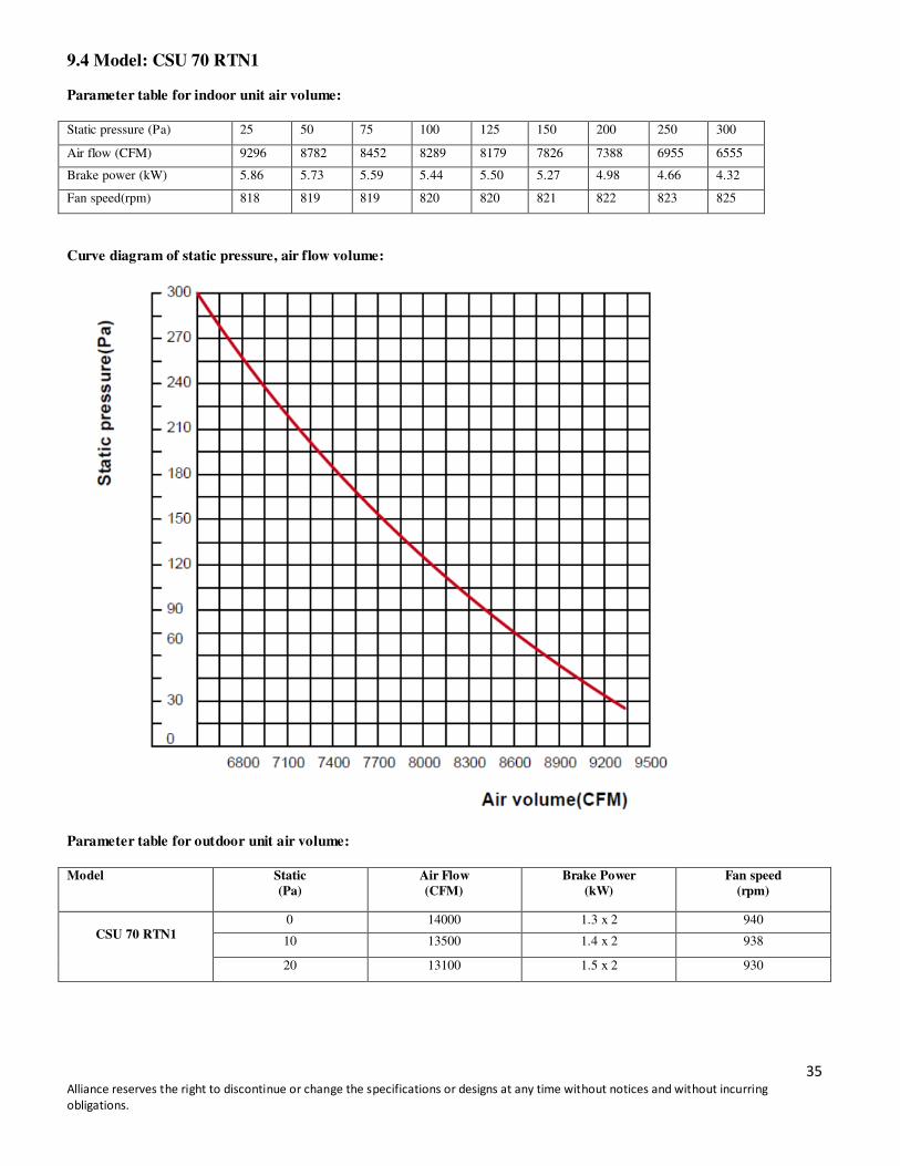
9.4 Model: CSU 70 RTN1
Parameter table for indoor unit air volume:
Static pressure (Pa) 25 50 75 100 125 150 200 250 300
Air flow (CFM) 9296 8782 8452 8289 8179 7826 7388 6955 6555
Brake power (kW) 5.86 5.73 5.59 5.44 5.50 5.27 4.98 4.66 4.32
Fan speed(rpm) 818 819 819 820 820 821 822 823 825
Curve diagram of static pressure, air flow volume:
Parameter table for outdoor unit air volume:
Model Static
(Pa)
Air Flow
(CFM)
Brake Power
(kW)
Fan speed
(rpm)
CSU 70 RTN1
0 14000 1.3 x 2 940
10 13500 1.4 x 2 938
20 13100 1.5 x 2 930
36 Alliance reserves the right to discontinue or change the specifications or designs at any time without notices and without incurring
obligations.
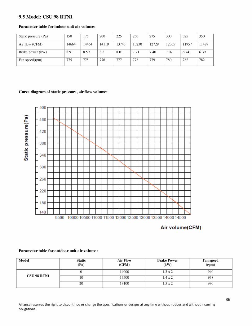
9.5 Model: CSU 98 RTN1
Parameter table for indoor unit air volume:
Static pressure (Pa) 150 175 200 225 250 275 300 325 350
Air flow (CFM) 14664 14464 14119 13743 13230 12729 12365 11957 11489
Brake power (kW) 8.91 8.59 8.3 8.01 7.71 7.40 7.07 6.74 6.39
Fan speed(rpm) 775 775 776 777 778 779 780 782 782
Curve diagram of static pressure, air flow volume:
Parameter table for outdoor unit air volume:
Model Static
(Pa)
Air Flow
(CFM)
Brake Power
(kW)
Fan speed
(rpm)
CSU 98 RTN1
0 14000 1.3 x 2 940
10 13500 1.4 x 2 938
20 13100 1.5 x 2 930
37 Alliance reserves the right to discontinue or change the specifications or designs at any time without notices and without incurring obligations.
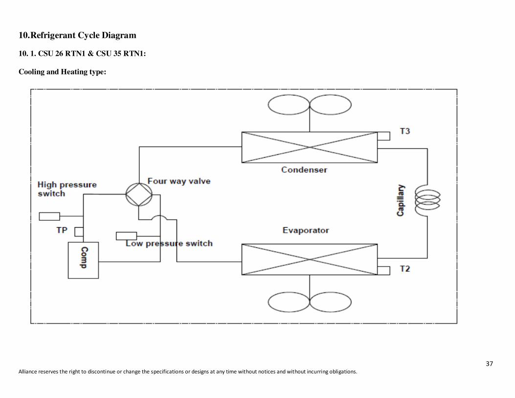
10. Refrigerant Cycle Diagram 10. 1. CSU 26 RTN1 & CSU 35 RTN1:
Cooling and Heating type:
38 Alliance reserves the right to discontinue or change the specifications or designs at any time without notices and without incurring obligations.
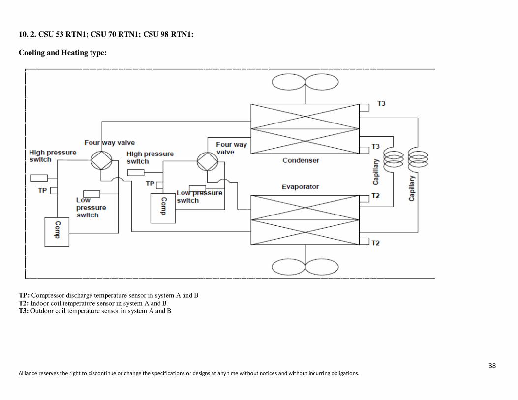
10. 2. CSU 53 RTN1; CSU 70 RTN1; CSU 98 RTN1:
Cooling and Heating type:
TP: Compressor discharge temperature sensor in system A and B
T2: Indoor coil temperature sensor in system A and B
T3: Outdoor coil temperature sensor in system A and B
39 Alliance reserves the right to discontinue or change the specifications or designs at any time without notices and without incurring
obligations.
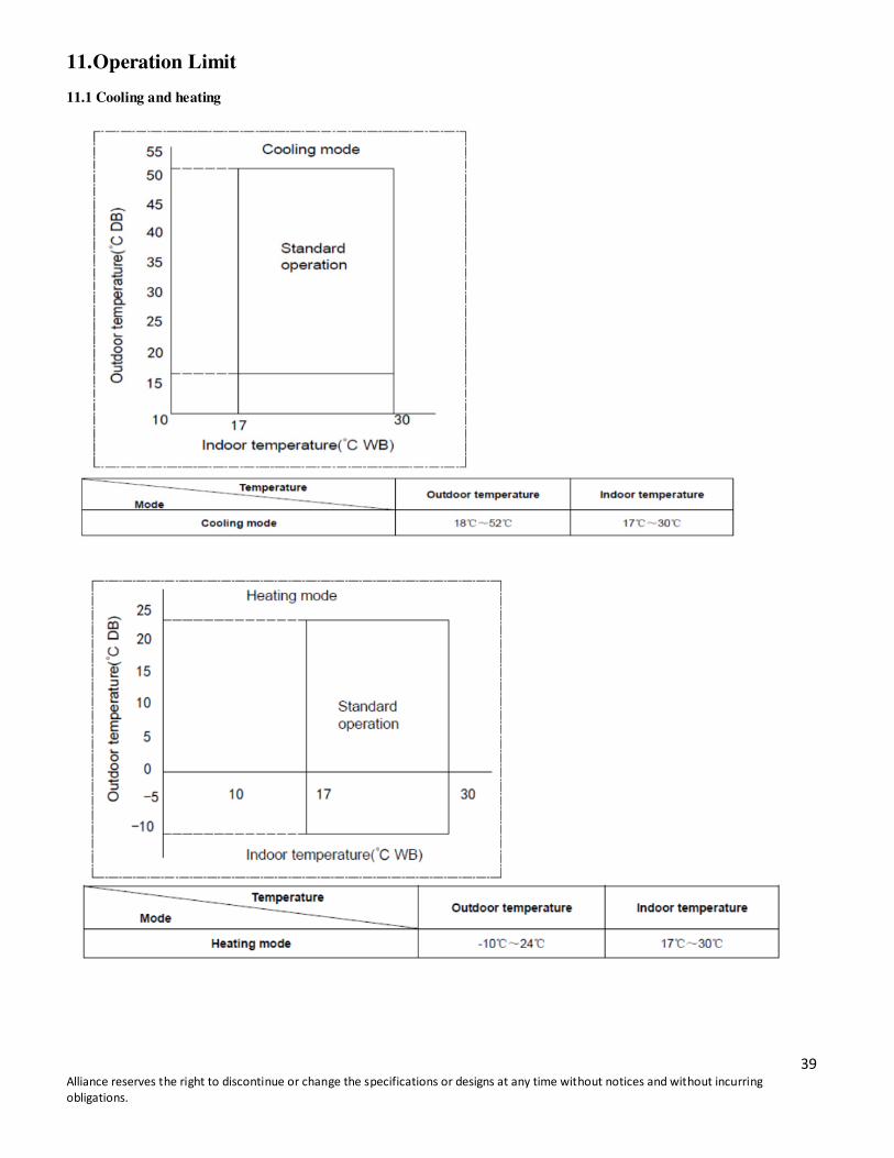
11. Operation Limit
11.1 Cooling and heating

40 Alliance reserves the right to discontinue or change the specifications or designs at any time without notices and without incurring
obligations.
12. Installation
12.1 Lifting
Rigging cables should have adequate capability to resist 3 times weight of unit. Before lift, please check and ensure
that hooks are holding tightly to unit and lifting angles are no less than 60°.
Cloth material or hard-paper should be padded in the contact place between unit and rigging cable. Rigging cable
should be entwined around at the hook to prevent danger by cable slip because of weight unbalance.
During lifting, no-one is to stand under the unit.
12.2 Service Space
1. The recommended clearances for single-unit installations are illustrated in following Fig.
These minimum requirements are not only an important consideration when determining unit placement, but they
are also essential to ensure adequate serviceability, maximum capacity, and peak operating efficiency. 2. Any
reduction of the unit clearances indicated in these illustrations may result in condenser coil starvation or the
recirculation of warm condenser air. Actual clearances which appear to be inadequate should be reviewed with a
local engineer.

41 Alliance reserves the right to discontinue or change the specifications or designs at any time without notices and without incurring
obligations.
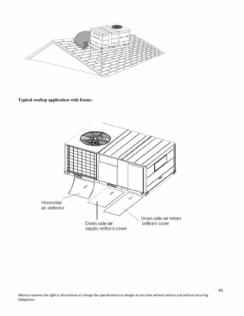
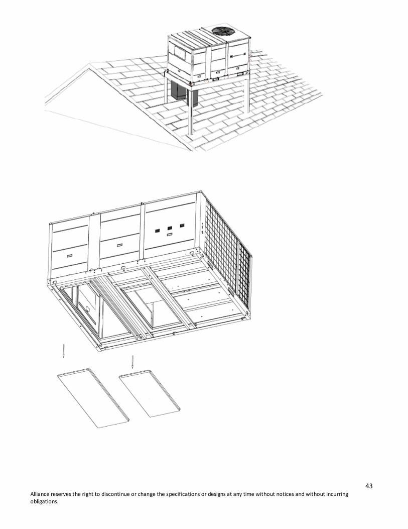
12.3 Rooftop -- units
For roof top applications using a field fabricated frame and ducts, according to the following procedure:
1) The frame must be located and secured by bolting or welding to the roof. Flashing is required.
2) The hole in the roof must be prepared in advance of installing the unit.
3) Secure the ducts to the roof.
4) Place the unit on the frame or roof curb.
5) Secure the unit to the frame or roof curb.
6) Insulate any ductwork outside of the structure with at least two (2) inches of insulation and then weatherproof.
There must be a weatherproof seal where the duct enters the structure.
7) Complete the installation according to the instructions.
Typical rooftop application with frame:
42 Alliance reserves the right to discontinue or change the specifications or designs at any time without notices and without incurring
obligations.
Typical rooftop application with frame:
43 Alliance reserves the right to discontinue or change the specifications or designs at any time without notices and without incurring
obligations.

44 Alliance reserves the right to discontinue or change the specifications or designs at any time without notices and without incurring
obligations.
12.4 Ground Level -- Horizontal Units
For ground level installations, the unit should be positioned on a pad the size of the unit or larger. The unit must be
level on the pad. The pad must not come in contact with the structure. Be sure the outdoor portion of the supply and
return air ducts are as short as possible.
Installation according to the following procedure:
1) Place the unit on the pad.
2) Attach the supply and return air ducts to the unit.
3) Insulate any ductwork outside of the structure with at least 2 inches of insulation and weatherproofing. There
must be a weatherproof seal where the duct enters the structure.
4) Complete the installation according to the instructions.
Typical ground level application:

45 Alliance reserves the right to discontinue or change the specifications or designs at any time without notices and without incurring
obligations.
12.5 Installation of condensate drain piping
12.6 Ductwork
1. Attaching horizontal ductwork to unit
1) All conditioned air ductwork should be insulated to minimize heating and cooling duct losses. Use a minimum of
two (2) inches of insulation with a vapor barrier. The outside ductwork must be weatherproofed between the unit
and the building.
2) When attaching ductwork to a horizontal unit, provide a flexible watertight connection to prevent noise
transmission from the unit to the ducts. The flexible connection must be indoors and made out of heavy canvas.
Note:
Do not draw the canvas taut between the solid ducts.

46 Alliance reserves the right to discontinue or change the specifications or designs at any time without notices and without incurring
obligations.
2. Attaching down flow ductwork to roof curb
Supply and return air flanges are provided on the roof curb for easy duct installation. All ductwork must be run and
attached to the curb before the unit is set into place.
Follow these guidelines for ductwork construction:
1) Connections to the unit should be made with three-inch canvas connectors to minimize noise and vibration
transmission.
2) Elbows with turning vanes or splitters are recommended to minimize air noise and resistance.
3) The first elbow in the ductwork leaving the unit should be no closer than two feet from the unit, to minimize
noise and resistance.
12.7 Wiring provision
Field wiring
The units are internally wired at the factory according to generally accepted electrical technology.
Required field wiring
Main power wiring to the unit control wiring between the control center and the unit, and earth wiring are required
in the field.
47 Alliance reserves the right to discontinue or change the specifications or designs at any time without notices and without incurring
obligations.
Required components
The following components are required: main power fuse, conduit coupling, and field supplied room thermostat.
Wire and fuse size selection for main power source.
Wire and fuse size should be selected in accordance with national standard, taking the designed maximum current
shall be the total of the compressor maximum current, condenser fan motor current and evaporator fan motor
current (refer to “electrical data”).
Wire size between room thermostat and unit.
The wire size between the room thermostat and the unit should be determined according to the following table,
because the 24V power source is applied to the control circuit.
Wiring length between room thermostat and unit (one way)
10m 15m 20m 30m 40m
Minimum wire size (mm
2)
0.5 0.5 0.75 0.75 1.0
13. Wired Controllers
13.1 Standard wired controller: KJR-12B/DP (T)-E
48 Alliance reserves the right to discontinue or change the specifications or designs at any time without notices and without incurring
obligations.
1. SAFETY PRECAUTIONS
The following contents are stated on the product and the operation manual, including usage, precautions against
personal harm and property loss, and the methods of using the product correctly and safely. After fully
understanding the following contents (identifiers and icons), read the text body and observe the following rules.
Identifier description
2. SUMMARIZE
Usage condition:
• Power supply: 5V DC.
• Operation temperature: -15-+43.
• Operation humidity: 40%-90%, RH.
3. FUNCTION SUMMARY
Main function:
• Connecting to indoor unit by A, B, C, D, E terminal;
• Button setting action mode.
• LCD display.
• Timer for rest time.
49 Alliance reserves the right to discontinue or change the specifications or designs at any time without notices and without incurring
obligations.
4. NAME AND FUNCTION OF INDICATORS ON THE CONTROLLER
• Operation mode indication:
When press " MODE " button, the following mode can be selected in circle. Auto→Cool →Dry→Heat→Fan
only→Auto. For cooling only model, heat mode is skipped.
• Timer :
When adjust setting on time or only on time is set, the "ON" is lighted.
When adjust setting off time or only off time is set, the "OFF" is lighted. If both ‘on’ and ‘off’ timer are set, both the
"ON" and "OFF" are lighted.
• Follow me function:
There is a temperature sensor inside the wire controller, after setting temperature, it will compare the two
temperatures, and the space of wire controller will be the same as setting temperature. It is available under cooling,
heating and auto mode.
• ON/OFF indication :
When it is on, the icon displays, otherwise it is extinguished.
• Fan speed indication :
There are four fan modes: low, middle, high, and auto. Some models have no middle fan, and then the middle fan is
seen as high speed.
• Lock:
When the “LOCK " button is pressed, the icon appears and other buttons are disabled. When pressed again, the icon
disappears.
50 Alliance reserves the right to discontinue or change the specifications or designs at any time without notices and without incurring
obligations.
• Temperature display zone:
Generally it displays setting temperature; it can be adjusted by press temperature button and . But in fan mode,
there is no display.
5. INSTALLATION METHOD
When a wired controller is needed, a small 5-way terminal should be added. Fix an infrared emitter with near the
receiver on the switch board. Connect its anode and cathode to A and B, and +5V, GND, RUN to C, D, E on the
switch board.
6. NAME AND OPERATION OF THE BUTTON ON THE WIRE CONTROLLER

51 Alliance reserves the right to discontinue or change the specifications or designs at any time without notices and without incurring
obligations.
• Mode button:
When pressing this button, the operation mode changes in the following sequence:
Remark: For the cooling only model, the heating mode is skipped.
• Timer on button :
Press this button, timer on function is active. Then with every press, the time increases 0.5h. After 10h, 1h increase
after each press. To cancel this function, just set it to "0.0".
• Timer off button:
Press this button, timer off function is active. Then with every press, the time increase 0.5h. After 10h, 1h increase
after each press. To cancel this function, just set it to "0.0".
• Follow me button:
When under cool, heat and auto mode, press this button, ‘follow me’ function is active. Press again, this function is
ineffective.
• Electrical heater button :
If press this button in heat mode, electrical heater function become ineffective.
• Reset button(hidden):
Use a 1mm stick to press in the little hole, then the current setting is canceled. The wired controller will enter into
original state.
• ON/OFF button:
When in off state, press this button, the indicator is on, the wire controller enters into on state, and sends setting
information to indoor PCB. When in on state, press this button, the indicator is off, and sends instruction. If timer
on or timer off has been set, it cancels this setting then sends instruction to stop the machine.
• Adjust button :
Set indoor temperature up. If press and hold, it will increase at 1 degree per 0.5 second.
• Adjust button :
Set indoor temperature down. If press and hold, it will decrease at 1 degree per 0.5 second.
52 Alliance reserves the right to discontinue or change the specifications or designs at any time without notices and without incurring
obligations.
• Swing button:
First pressing: start swing function; second pressing: stop swing. (Match to some model with swing function).
• Economy operation button:
Press this button, the indoor unit operates in economy mode, press it again, exit this mode (it may be ineffective for
some models)
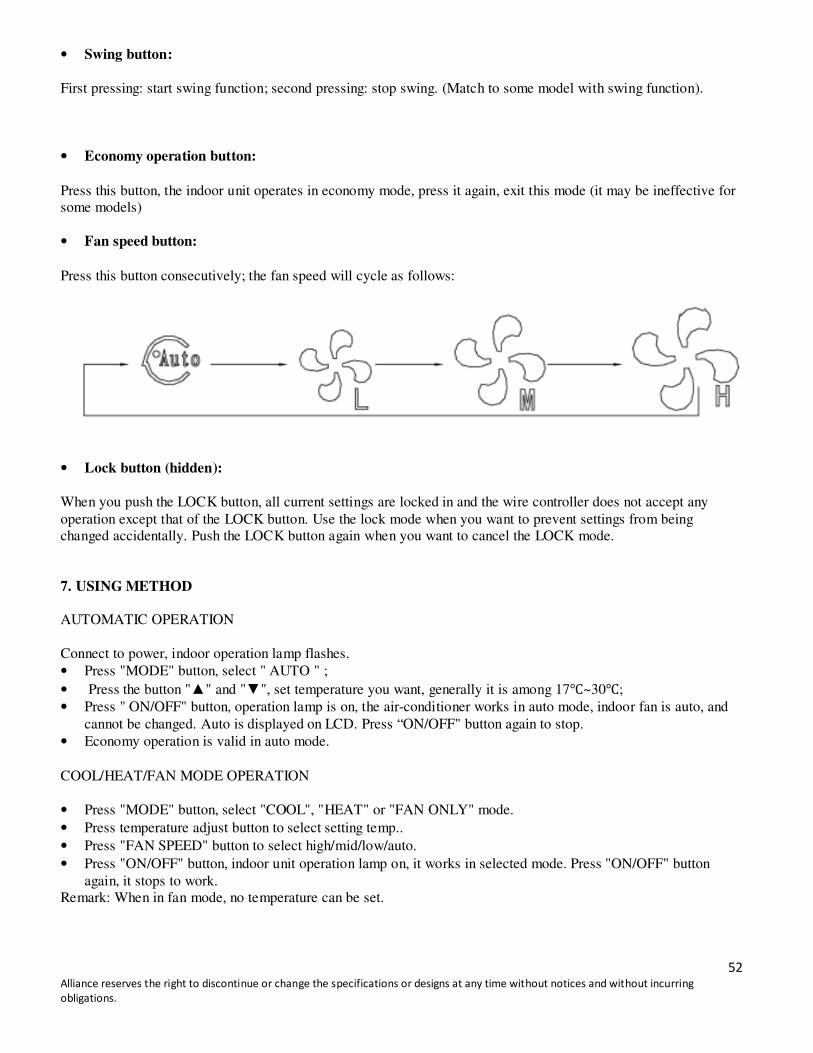
• Fan speed button:
Press this button consecutively; the fan speed will cycle as follows:
• Lock button (hidden):
When you push the LOCK button, all current settings are locked in and the wire controller does not accept any
operation except that of the LOCK button. Use the lock mode when you want to prevent settings from being
changed accidentally. Push the LOCK button again when you want to cancel the LOCK mode.
7. USING METHOD
AUTOMATIC OPERATION
Connect to power, indoor operation lamp flashes.
• Press "MODE" button, select " AUTO " ;
• Press the button "" and "", set temperature you want, generally it is among 17~30;
• Press " ON/OFF" button, operation lamp is on, the air-conditioner works in auto mode, indoor fan is auto, and
cannot be changed. Auto is displayed on LCD. Press “ON/OFF" button again to stop.
• Economy operation is valid in auto mode.
COOL/HEAT/FAN MODE OPERATION
• Press "MODE" button, select "COOL", "HEAT" or "FAN ONLY" mode.
• Press temperature adjust button to select setting temp..
• Press "FAN SPEED" button to select high/mid/low/auto.
• Press "ON/OFF" button, indoor unit operation lamp on, it works in selected mode. Press "ON/OFF" button
again, it stops to work.
Remark: When in fan mode, no temperature can be set.

53 Alliance reserves the right to discontinue or change the specifications or designs at any time without notices and without incurring
obligations.
DRY OPERATION
• Press “MODE” button, select “DRY " mode.
• Press temperature adjust button to select setting temp.
• Press “ON/OFF " button, indoor unit operation lamp on, it works in dry mode. Press ON/OFF button again, it
stops working.
• In dry mode, economy operation and fan speed are ineffective.
TIMER SETTING
Timer on only:
• Press “TIME ON” button, it displays "SET" on LCD, and displays " H " and "ON" , awaiting timer on setting.
• Press “timer" on button repeatedly to adjust time setting.
• If press this button and hold down, the time will increase at 0.5h, after 10h, it increases at 1h.
• After setting 0.5 second, the wire controller sends timer on information, it is finished.
Timer off only:
• Press "TIME OFF " button, it displays "SET" on LCD, and display " H " and ON, awaiting timer on setting.
• If press this button and hold down, the time will increase at 0.5h, after 10h, it increases at 1h.
• After setting 0.5 second, the wire controller sends timer off information, it is finished.
TIMER ON AND TIMER OFF BOTH
• Set timer on time as the corresponding step 1 and 2.
• Set timer off time as the corresponding step 1 and 2.
• Timer off time must be longer than timer on time.
• 0.5 second after setting, the wire controller sends information, the setting is finished.
CHANGE TIMER
If there is timer of changing time is required, press corresponding button to revise it. If cancel timer, change time to
0.0.
NOTE: The timer time is relative time, that is delay after setting time (i.e: setting time is 8:05 A,M). So when timer
is set, the standard time cannot be adjusted
14. TECHNICAL INDICATION AND REQUIREMENT
EMC and EMI comply with the CE certification requirements.
54 Alliance reserves the right to discontinue or change the specifications or designs at any time without notices and without incurring
obligations.
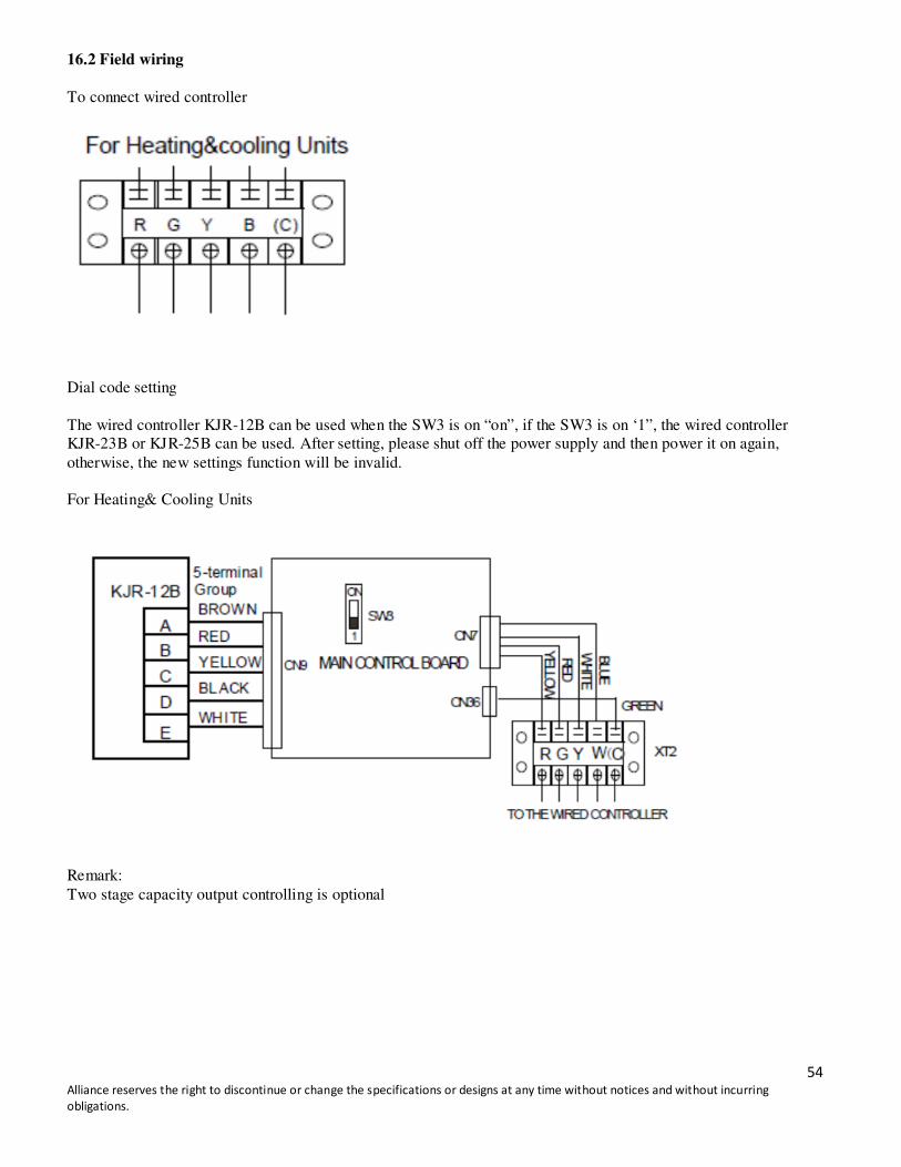
16.2 Field wiring
To connect wired controller
Dial code setting
The wired controller KJR-12B can be used when the SW3 is on “on”, if the SW3 is on ‘1”, the wired controller
KJR-23B or KJR-25B can be used. After setting, please shut off the power supply and then power it on again,
otherwise, the new settings function will be invalid.
For Heating& Cooling Units
Remark:
Two stage capacity output controlling is optional

55 Alliance reserves the right to discontinue or change the specifications or designs at any time without notices and without incurring
obligations.
15. Error Code
Type Content Code Remarks
Normal Standby --
Normal Constraint cool On
Normal Run 10. Manual reset
Error Compressor phase sequence error or phase default E0 Manual reset
Error Outdoor coil temp. sensor in sys. A error E1 Manual reset
Error Outdoor coil temp. sensor in sys. B error E2 Manual reset
Error Indoor coil temp. sensor in sys. A error E5 Manual reset
Error Indoor coil temp. sensor in sys. B error E6 Manual reset
Error Indoor temp. sensor error E9 Manual reset
Error Outdoor ambient temp. sensor error EA Manual reset
Error Wire controller output error Eb Manual reset
Protection Over current protection in sys. A P0 Auto reset
Protection Over current protection in sys. B P1 Auto reset
Protection Over current protection for indoor fan P2 Auto reset
Protection Comprehensive protection for outdoor fan P3 Auto reset
Protection Protection for Hi./Lo. Pressure or exhaust temp. in sys. A P4 Comprehensive protection in sys. A
Protection Protection for Hi./Lo. Pressure or exhaust temp. in sys. B P5 Comprehensive protection in sys. B
Protection T2 evaporator Hi-temperature protection stop outdoor
unit fan
P6 Auto reset
Protection T2 evaporator Hi- temperature protection then stop
outdoor unit fan and compressor
P7 Auto reset
Protection Protection for condenser Hi-temp. in sys. A P8 Auto reset
Protection Protection for condenser Hi-temp. in sys. B P9 Auto reset
Protection Anti-freezing protection for evaporator in sys. A Pc Auto reset
Protection Anti-freezing protection for evaporator in sys. B Pd Auto reset
Protection Defrosting dF Auto reset
16. Troubleshooting
Item Content Error code
1 Indoor fan motor didn’t run. --
2 Compressor didn’t run. --
3 T3 temp sensor error. EA
4 Check if the low pressure protection is normal. --
5 Outdoor fan motor didn’t run. --
6 Four ways valve didn’t work. --
7 Condenser high temp protection. P8,P9
56 Alliance reserves the right to discontinue or change the specifications or designs at any time without notices and without incurring
obligations.
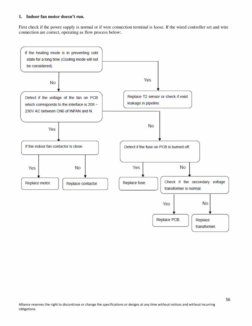
1. Indoor fan motor doesn’t run.
First check if the power supply is normal or if wire connection terminal is loose. If the wired controller set and wire
connection are correct, operating as flow process below:.
57 Alliance reserves the right to discontinue or change the specifications or designs at any time without notices and without incurring
obligations.
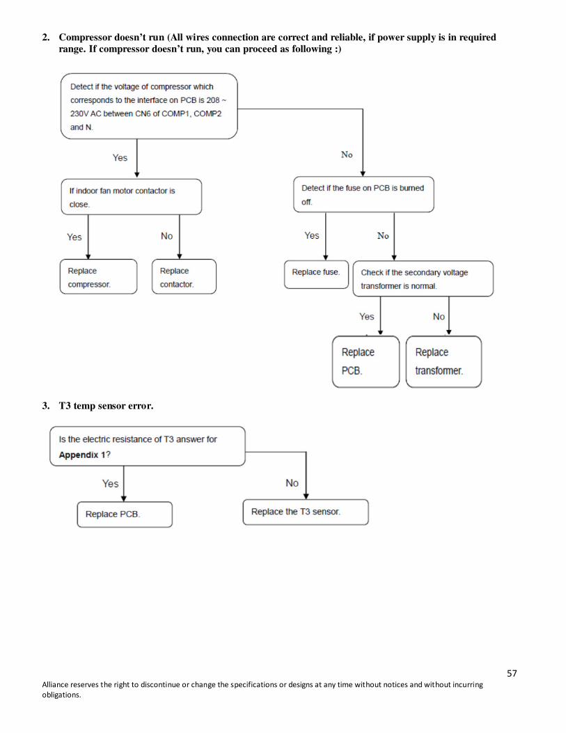
2. Compressor doesn’t run (All wires connection are correct and reliable, if power supply is in required
range. If compressor doesn’t run, you can proceed as following :)
3. T3 temp sensor error.

58 Alliance reserves the right to discontinue or change the specifications or designs at any time without notices and without incurring
obligations.
4. Check if the low pressure protection is normal.
5. Outdoor fan motor doesn’t run.

59 Alliance reserves the right to discontinue or change the specifications or designs at any time without notices and without incurring
obligations.
6. Four ways valve don’t work.

60 Alliance reserves the right to discontinue or change the specifications or designs at any time without notices and without incurring
obligations.
7. Condenser high temperature protection
61 Alliance reserves the right to discontinue or change the specifications or designs at any time without notices and without incurring
obligations.
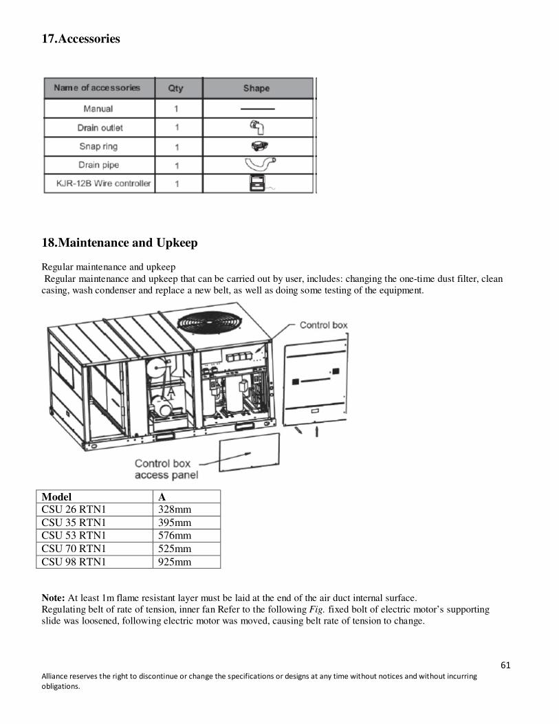
17. Accessories
18. Maintenance and Upkeep
Regular maintenance and upkeep
Regular maintenance and upkeep that can be carried out by user, includes: changing the one-time dust filter, clean
casing, wash condenser and replace a new belt, as well as doing some testing of the equipment.
Model A CSU 26 RTN1 328mm
CSU 35 RTN1 395mm
CSU 53 RTN1 576mm
CSU 70 RTN1 525mm
CSU 98 RTN1 925mm
Note: At least 1m flame resistant layer must be laid at the end of the air duct internal surface.
Regulating belt of rate of tension, inner fan Refer to the following Fig. fixed bolt of electric motor’s supporting
slide was loosened, following electric motor was moved, causing belt rate of tension to change.
62 Alliance reserves the right to discontinue or change the specifications or designs at any time without notices and without incurring
obligations.
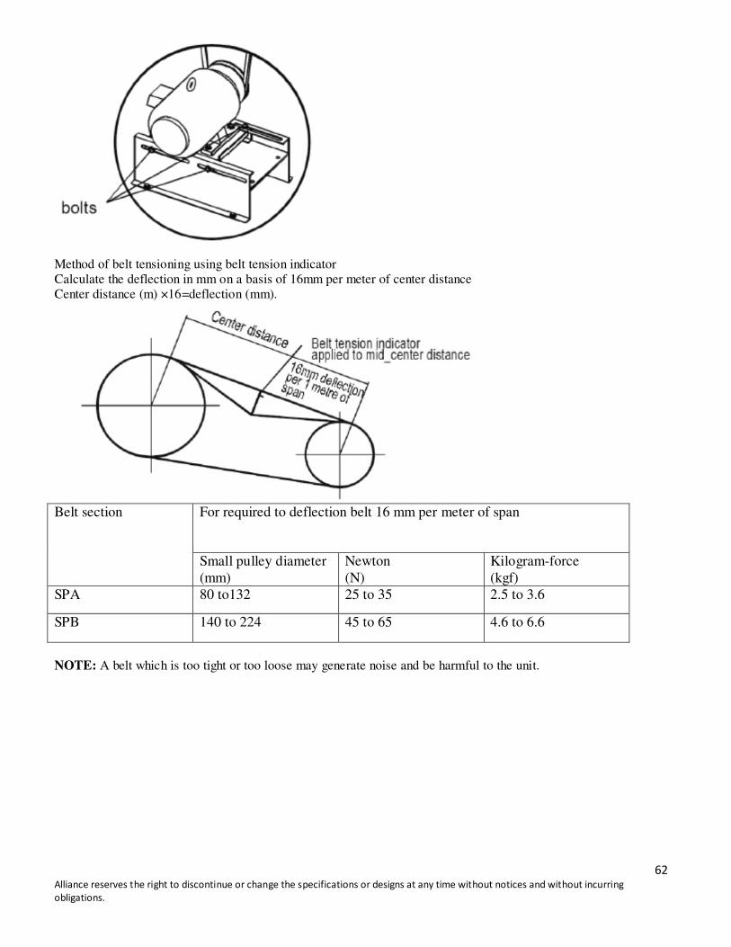
Method of belt tensioning using belt tension indicator
Calculate the deflection in mm on a basis of 16mm per meter of center distance
Center distance (m) ×16=deflection (mm).
Belt section For required to deflection belt 16 mm per meter of span
Small pulley diameter
(mm)
Newton
(N)
Kilogram-force
(kgf)
SPA 80 to132 25 to 35 2.5 to 3.6
SPB 140 to 224 45 to 65 4.6 to 6.6
NOTE: A belt which is too tight or too loose may generate noise and be harmful to the unit.
63 Alliance reserves the right to discontinue or change the specifications or designs at any time without notices and without incurring
obligations.
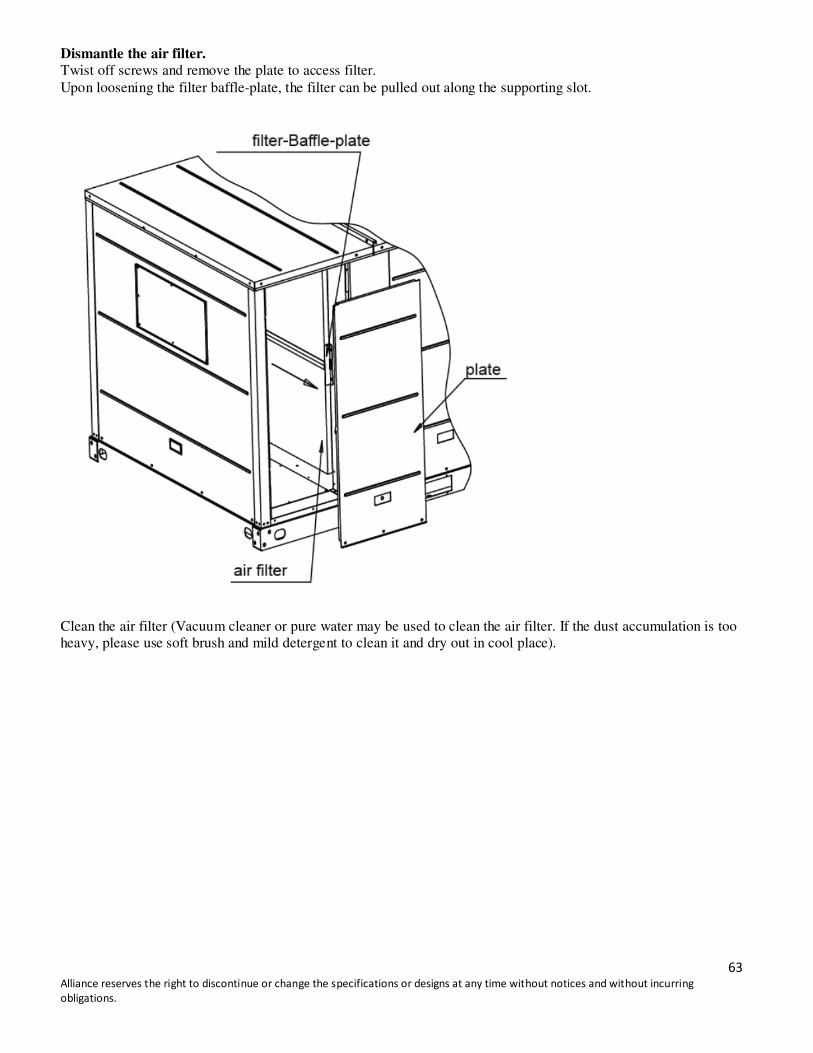
Dismantle the air filter.
Twist off screws and remove the plate to access filter.
Upon loosening the filter baffle-plate, the filter can be pulled out along the supporting slot.
Clean the air filter (Vacuum cleaner or pure water may be used to clean the air filter. If the dust accumulation is too
heavy, please use soft brush and mild detergent to clean it and dry out in cool place).
64 Alliance reserves the right to discontinue or change the specifications or designs at any time without notices and without incurring
obligations.
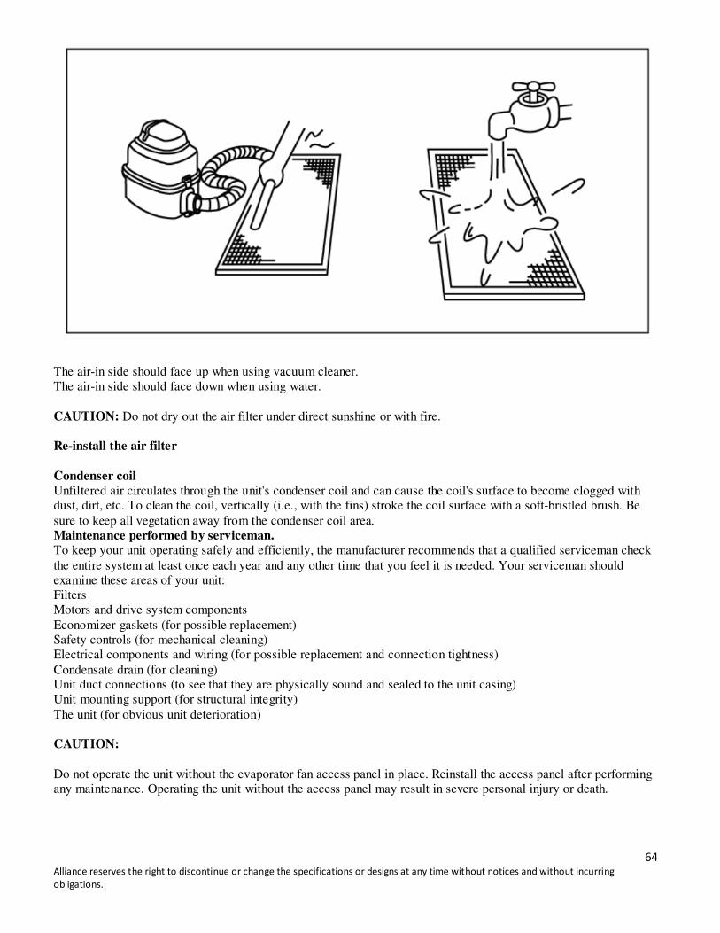
The air-in side should face up when using vacuum cleaner.
The air-in side should face down when using water.
CAUTION: Do not dry out the air filter under direct sunshine or with fire.
Re-install the air filter
Condenser coil
Unfiltered air circulates through the unit's condenser coil and can cause the coil's surface to become clogged with
dust, dirt, etc. To clean the coil, vertically (i.e., with the fins) stroke the coil surface with a soft-bristled brush. Be
sure to keep all vegetation away from the condenser coil area.
Maintenance performed by serviceman.
To keep your unit operating safely and efficiently, the manufacturer recommends that a qualified serviceman check
the entire system at least once each year and any other time that you feel it is needed. Your serviceman should
examine these areas of your unit:
Filters
Motors and drive system components
Economizer gaskets (for possible replacement)
Safety controls (for mechanical cleaning)
Electrical components and wiring (for possible replacement and connection tightness)
Condensate drain (for cleaning)
Unit duct connections (to see that they are physically sound and sealed to the unit casing)
Unit mounting support (for structural integrity)
The unit (for obvious unit deterioration)
CAUTION:
Do not operate the unit without the evaporator fan access panel in place. Reinstall the access panel after performing
any maintenance. Operating the unit without the access panel may result in severe personal injury or death.
65 Alliance reserves the right to discontinue or change the specifications or designs at any time without notices and without incurring
obligations.
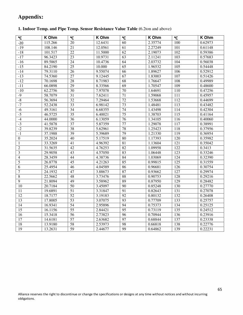
Appendix:
1. Indoor Temp. and Pipe Temp. Sensor Resistance Value Table (6.2ton and above)
K Ohm K Ohm K Ohm K Ohm
-20 115.266 20 12.6431 60 2.35774 100 0.62973
-19 108.146 21 12.0561 61 2.27249 101 0.61148
-18 101.517 22 11.5000 62 2.19073 102 0.59386
-17 96.3423 23 10.9731 63 2.11241 103 0.57683
-16 89.5865 24 10.4736 64 2.03732 104 0.56038
-15 84.2190 25 10.000 65 1.96532 105 0.54448
-14 79.3110 26 9.55074 66 1.89627 106 0.52912
-13 74.5360 27 9.12445 67 1.83003 107 0.51426
-12 70.1698 28 8.71983 68 1.76647 108 0.49989
-11 66.0898 29 8.33566 69 1.70547 109 0.48600
-10 62.2756 30 7.97078 70 1.64691 110 0.47256
-9 58.7079 31 7.62411 71 1.59068 111 0.45957
-8 56.3694 32 7.29464 72 1.53668 112 0.44699
-7 52.2438 33 6.98142 73 1.48481 113 0.43482
-6 49.3161 34 6.68355 74 1.43498 114 0.42304
-5 46.5725 35 6.40021 75 1.38703 115 0.41164
-4 44.0000 36 6.13059 76 1.34105 116 0.40060
-3 41.5878 37 5.87359 77 1.29078 117 0.38991
-2 39.8239 38 5.62961 78 1.25423 118 0.37956
-1 37.1988 39 5.39689 79 1.21330 119 0.36954
0 35.2024 40 5.17519 80 1.17393 120 0.35982
1 33.3269 41 4.96392 81 1.13604 121 0.35042
2 31.5635 42 4.76253 82 1.09958 122 0.3413
3 29.9058 43 4.57050 83 1.06448 123 0.33246
4 28.3459 44 4.38736 84 1.03069 124 0.32390
5 26.8778 45 4.21263 85 0.99815 125 0.31559
6 25.4954 46 4.04589 86 0.96681 126 0.30754
7 24.1932 47 3.88673 87 0.93662 127 0.29974
8 22.5662 48 3.73476 88 0.90753 128 0.29216
9 21.8094 49 3.58962 89 0.87950 129 0.28482
10 20.7184 50 3.45097 90 0.85248 130 0.27770
11 19.6891 51 3.31847 91 0.82643 131 0.27078
12 18.7177 52 3.19183 92 0.80132 132 0.26408
13 17.8005 53 3.07075 93 0.77709 133 0.25757
14 16.9341 54 2.95896 94 0.75373 134 0.25125
15 16.1156 55 2.84421 95 0.73119 135 0.24512
16 15.3418 56 2.73823 96 0.70944 136 0.23916
17 14.6181 57 2.63682 97 0.68844 137 0.23338
18 13.9180 58 2.53973 98 0.66818 138 0.22776
19 13.2631 59 2.44677 99 0.64862 139 0.22231

66 Alliance reserves the right to discontinue or change the specifications or designs at any time without notices and without incurring
obligations.
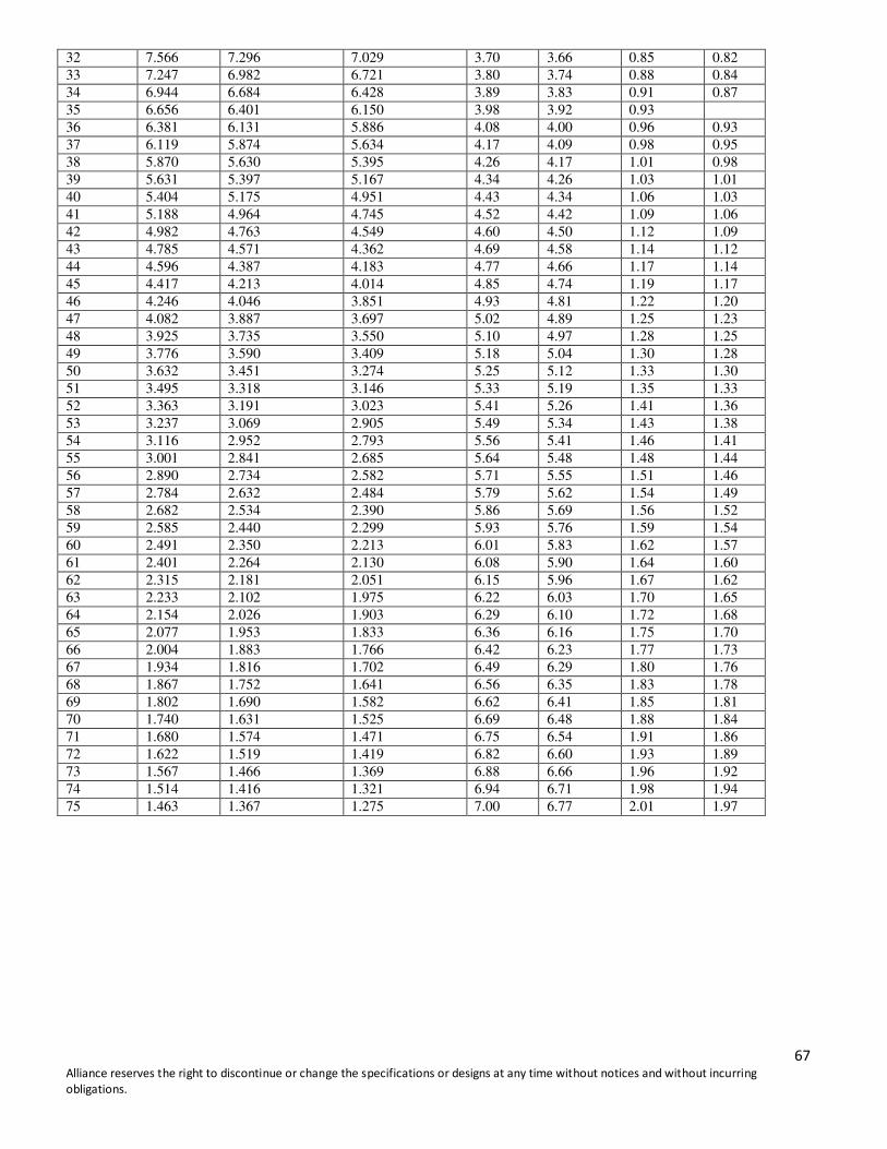
2. Indoor Temp. and Pipe Temp. Sensor Resistance Value Table (5ton)
Temp
Resistance(KΩ) Resist.tol (%) Temp.tol()
(((( ))))
Rmax R(t)Normal Rmin MAX(+) MIN(-) MAX(+) MIN(-)
-20 116.539 106.732 96.920 9.19 9.19 1.59 1.59
-19 110.231 100.552 91.451 9.63 9.05 1.57 1.57
-18 103.743 94.769 86.328 9.47 8.91 1.56 1.55
-17 97.673 89.353 81.525 9.31 8.76 1.54 1.54
-16 91.990 84.278 77.017 9.15 8.62 1.53 1.52
-15 86.669 79.521 72.788 8.99 8.47 1.51 1.50
-14 81.684 75.059 68.815 8.83 8.32 1.49 1.48
-13 77.013 70.873 65.083 8.66 8.17 1.47 1.47
-12 72.632 66.943 61.574 8.50 8.02 1.45 1.45
-11 68.523 63.252 58.274 8.33 7.87 1.44 1.43
-10 64.668 59.784 55.169 8.17 7.72 1.42 1.41
-9 61.048 56.524 52.246 8.00 7.57 1.40 1.39
-8 57.649 53.458 49.492 7.84 7.42 1.38 1.37
-7 54.456 50.575 46.899 7.67 7.27 1.35 1.35
-6 51.456 47.862 44.455 7.51 7.12 1.33 1.32
-5 48.636 45.308 42.150 7.35 6.97 1.31 1.30
-4 45.984 42.903 39.977 7.18 6.82 1.29 1.28
-3 43.490 40.638 37.927 7.02 6.67 1.27 1.26
-2 41.144 38.504 35.992 6.86 6.52 1.25 1.24
-1 38.935 36.492 34.165 6.70 6.38 1.23 1.21
0 36.857 34.596 32.440 6.53 6.23 1.21 1.19
1 34.898 32.807 30.810 6.38 6.09 1.18 1.17
2 33.055 31.120 29.271 6.22 5.94 1.16 1.15
3 31.317 29.528 27.815 6.06 5.80 1.14 1.12
4 29.681 28.026 26.440 5.90 5.66 1.12 1.10
5 28.138 26.608 25.140 5.75 5.52 1.10 1.08
6 26.682 25.268 23.909 5.60 5.38 1.07 1.06
7 25.310 24.003 22.745 5.45 5.24 1.05 1.03
8 24.016 22.808 21.644 5.30 5.10 1.03 1.01
9 22.794 21.678 20.601 5.15 4.97 1.01 0.99
10 21.641 20.610 19.614 5.00 4.83 0.99 0.97
11 20.553 19.601 18.680 4.86 4.70 0.96 0.94
12 19.525 18.646 17.794 4.71 4.57 0.94 0.92
13 18.554 17.743 16.955 4.57 4.44 0.92 0.90
14 17.636 16.888 16.160 4.43 4.31 0.90 0.88
15 16.769 16.079 15.406 4.29 4.19 0.88 0.85
16 15.949 15.313 14.691 4.15 4.06 0.86 0.83
17 15.174 14.588 14.014 4.02 3.94 0.84 0.81
18 14.442 13.902 13.372 3.89 3.81 0.81 0.79
19 13.748 13.251 12.762 3.75 3.69 0.79 0.76
20 13.093 12.635 12.183 3.62 3.57 0.77 0.74
21 12.471 12.050 11.634 3.50 3.46 0.75 0.72
22 11.883 11.496 11.112 3.37 3.34 0.73 0.70
23 11.327 10.971 10.617 3.25 3.23 0.71 0.68
24 10.800 10.473 10.147 3.12 3.11 0.69 0.66
25 10.300 10.000 9.700 3.00 3.00 0.67 0.63
26 9.848 9.551 9.255 3.11 3.10 0.69 0.66
27 9.418 9.125 8.834 3.21 3.19 0.72 0.69
28 9.010 8.721 8.434 3.31 3.29 0.75 0.71
29 8.621 8.337 8.055 3.41 3.38 0.77 0.74
30 8.252 7.972 7.695 3.51 3.47 0.80
31 7.900 7.625 7.353 3.61 3.57 0.83 0.79
67 Alliance reserves the right to discontinue or change the specifications or designs at any time without notices and without incurring
obligations.
32 7.566 7.296 7.029 3.70 3.66 0.85 0.82
33 7.247 6.982 6.721 3.80 3.74 0.88 0.84
34 6.944 6.684 6.428 3.89 3.83 0.91 0.87
35 6.656 6.401 6.150 3.98 3.92 0.93
36 6.381 6.131 5.886 4.08 4.00 0.96 0.93
37 6.119 5.874 5.634 4.17 4.09 0.98 0.95
38 5.870 5.630 5.395 4.26 4.17 1.01 0.98
39 5.631 5.397 5.167 4.34 4.26 1.03 1.01
40 5.404 5.175 4.951 4.43 4.34 1.06 1.03
41 5.188 4.964 4.745 4.52 4.42 1.09 1.06
42 4.982 4.763 4.549 4.60 4.50 1.12 1.09
43 4.785 4.571 4.362 4.69 4.58 1.14 1.12
44 4.596 4.387 4.183 4.77 4.66 1.17 1.14
45 4.417 4.213 4.014 4.85 4.74 1.19 1.17
46 4.246 4.046 3.851 4.93 4.81 1.22 1.20
47 4.082 3.887 3.697 5.02 4.89 1.25 1.23
48 3.925 3.735 3.550 5.10 4.97 1.28 1.25
49 3.776 3.590 3.409 5.18 5.04 1.30 1.28
50 3.632 3.451 3.274 5.25 5.12 1.33 1.30
51 3.495 3.318 3.146 5.33 5.19 1.35 1.33
52 3.363 3.191 3.023 5.41 5.26 1.41 1.36
53 3.237 3.069 2.905 5.49 5.34 1.43 1.38
54 3.116 2.952 2.793 5.56 5.41 1.46 1.41
55 3.001 2.841 2.685 5.64 5.48 1.48 1.44
56 2.890 2.734 2.582 5.71 5.55 1.51 1.46
57 2.784 2.632 2.484 5.79 5.62 1.54 1.49
58 2.682 2.534 2.390 5.86 5.69 1.56 1.52
59 2.585 2.440 2.299 5.93 5.76 1.59 1.54
60 2.491 2.350 2.213 6.01 5.83 1.62 1.57
61 2.401 2.264 2.130 6.08 5.90 1.64 1.60
62 2.315 2.181 2.051 6.15 5.96 1.67 1.62
63 2.233 2.102 1.975 6.22 6.03 1.70 1.65
64 2.154 2.026 1.903 6.29 6.10 1.72 1.68
65 2.077 1.953 1.833 6.36 6.16 1.75 1.70
66 2.004 1.883 1.766 6.42 6.23 1.77 1.73
67 1.934 1.816 1.702 6.49 6.29 1.80 1.76
68 1.867 1.752 1.641 6.56 6.35 1.83 1.78
69 1.802 1.690 1.582 6.62 6.41 1.85 1.81
70 1.740 1.631 1.525 6.69 6.48 1.88 1.84
71 1.680 1.574 1.471 6.75 6.54 1.91 1.86
72 1.622 1.519 1.419 6.82 6.60 1.93 1.89
73 1.567 1.466 1.369 6.88 6.66 1.96 1.92
74 1.514 1.416 1.321 6.94 6.71 1.98 1.94
75 1.463 1.367 1.275 7.00 6.77 2.01 1.97