root locus - · pdf fileroot locus for a second-order system when k e
TRANSCRIPT

Root Locus

Closed-loop control system with a variable
parameter K.
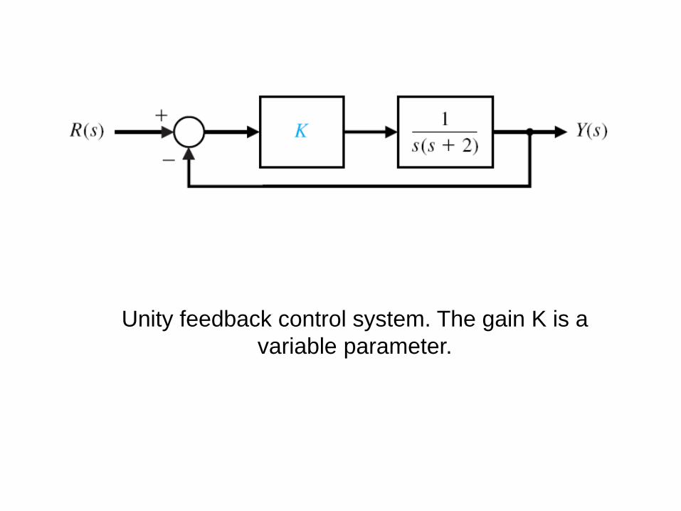
Unity feedback control system. The gain K is a
variable parameter.
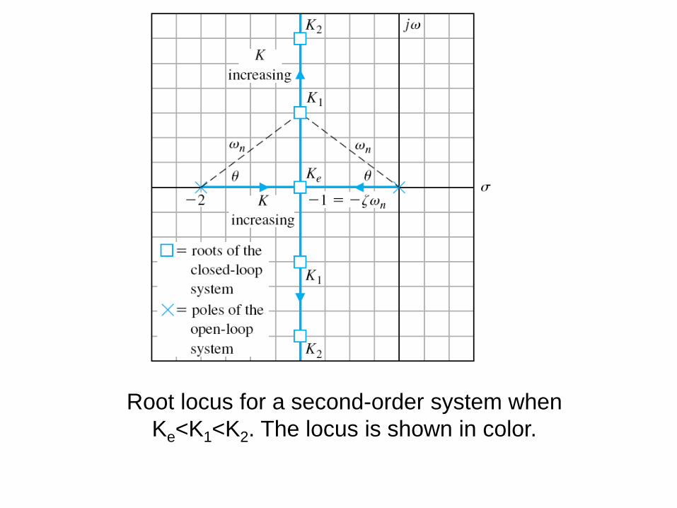
Root locus for a second-order system when
Ke<K1<K2. The locus is shown in color.

Evaluation of the angle and gain at s1,for
gain K=K1.
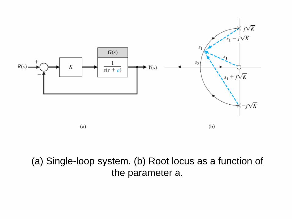
(a) Single-loop system. (b) Root locus as a function of
the parameter a.
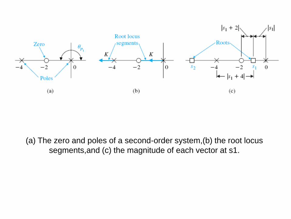
(a) The zero and poles of a second-order system,(b) the root locus
segments,and (c) the magnitude of each vector at s1.
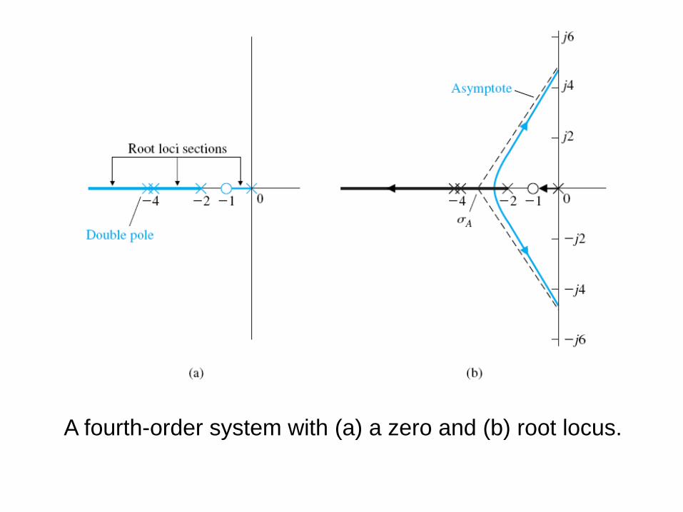
A fourth-order system with (a) a zero and (b) root locus.
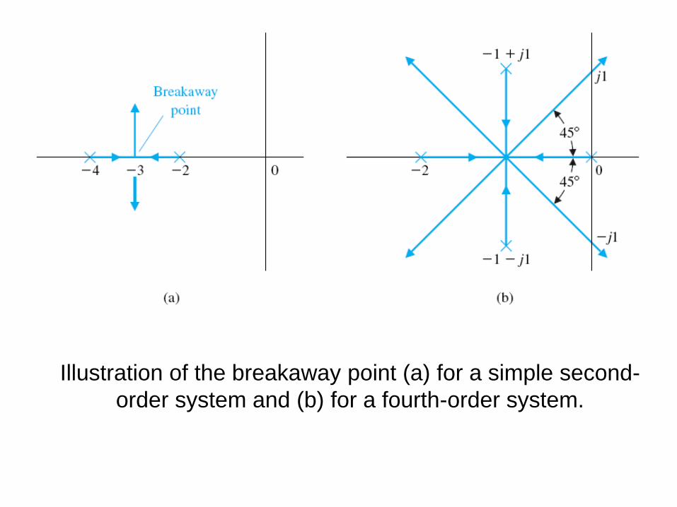
Illustration of the breakaway point (a) for a simple second-
order system and (b) for a fourth-order system.
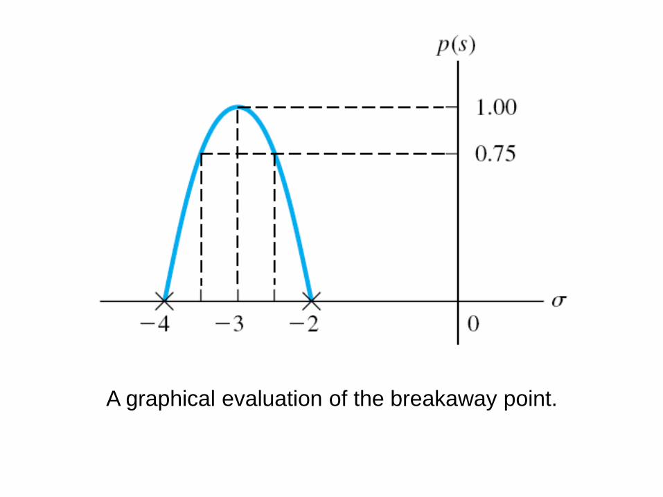
A graphical evaluation of the breakaway point.

Closed-loop system.
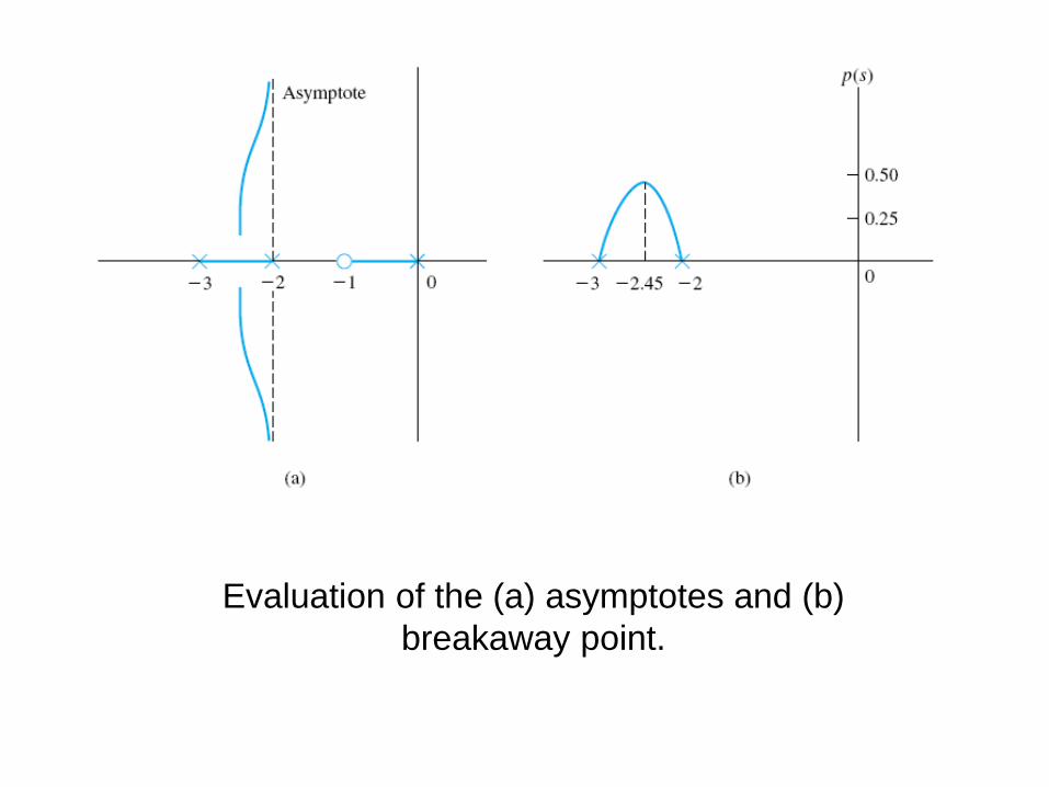
Evaluation of the (a) asymptotes and (b)
breakaway point.
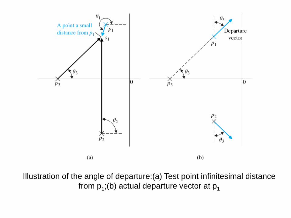
Illustration of the angle of departure:(a) Test point infinitesimal distance
from p1;(b) actual departure vector at p1
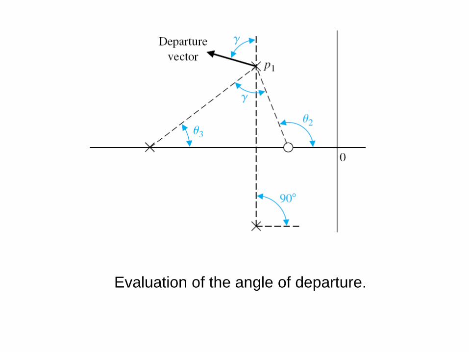
Evaluation of the angle of departure.

The root locus for Example 7.4:locating (a)
the poles and (b) the asymptotes.
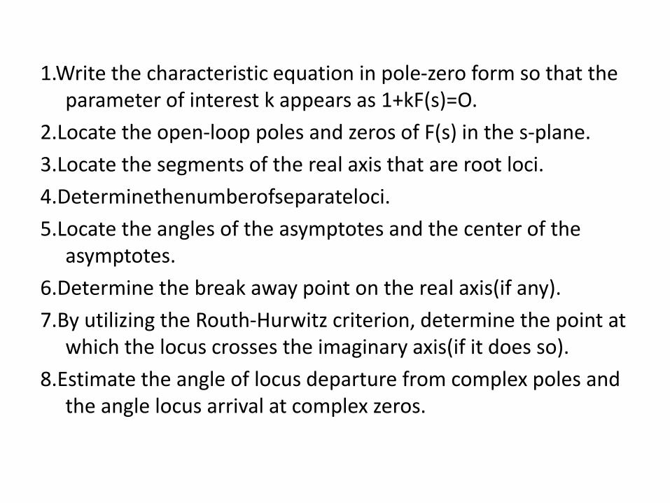
1.Write the characteristic equation in pole-zero form so that the parameter of interest k appears as 1+kF(s)=O.
2.Locate the open-loop poles and zeros of F(s) in the s-plane.
3.Locate the segments of the real axis that are root loci.
4.Determinethenumberofseparateloci.
5.Locate the angles of the asymptotes and the center of the asymptotes.
6.Determine the break away point on the real axis(if any).
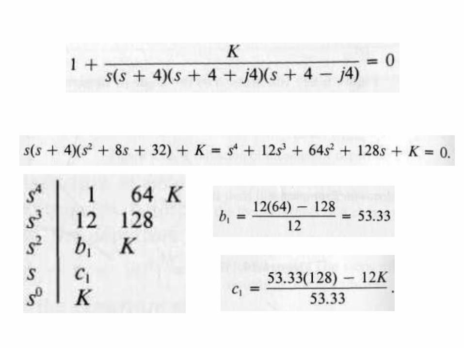
7.By utilizing the Routh-Hurwitz criterion, determine the point at which the locus crosses the imaginary axis(if it does so).
8.Estimate the angle of locus departure from complex poles and the angle locus arrival at complex zeros.


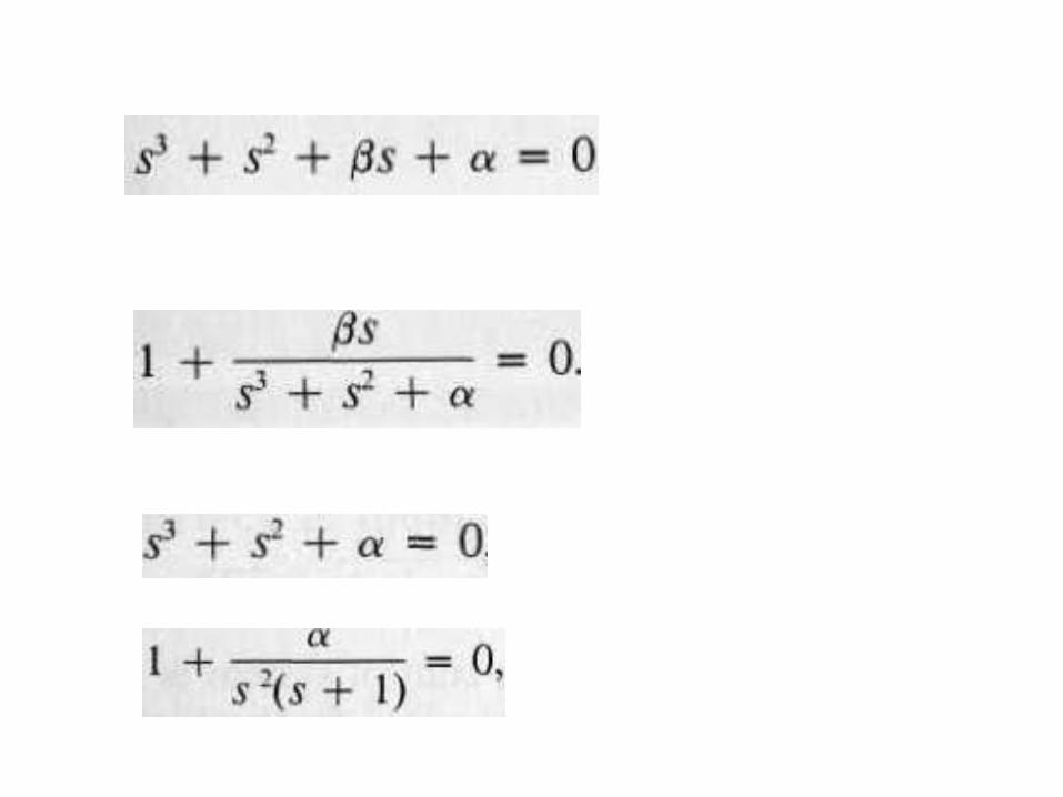
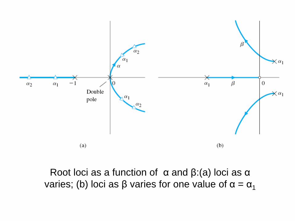
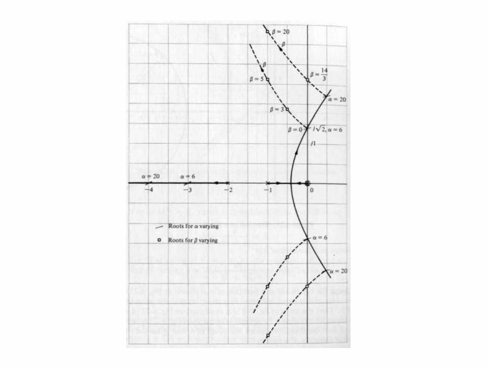
Root loci as a function of α and β:(a) loci as α
varies; (b) loci as β varies for one value of α = α1
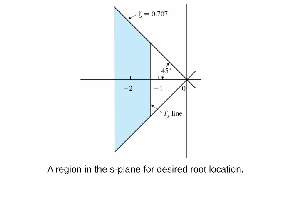
A region in the s-plane for desired root location.


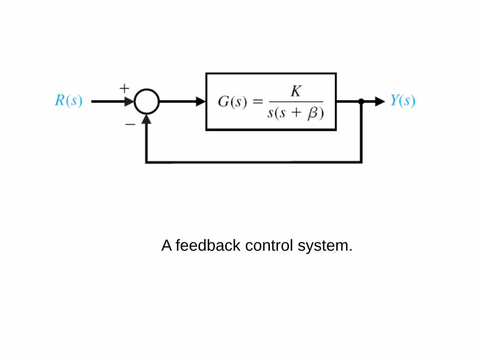
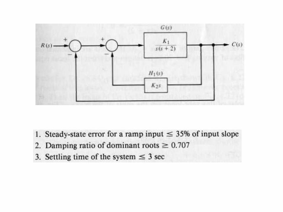
A feedback control system.
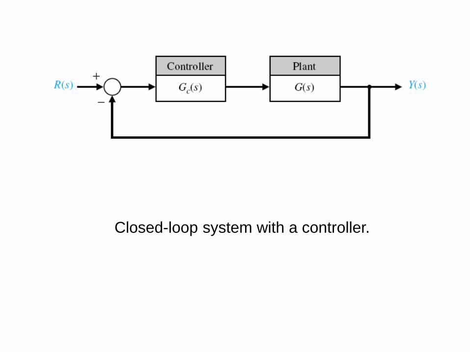
Closed-loop system with a controller.
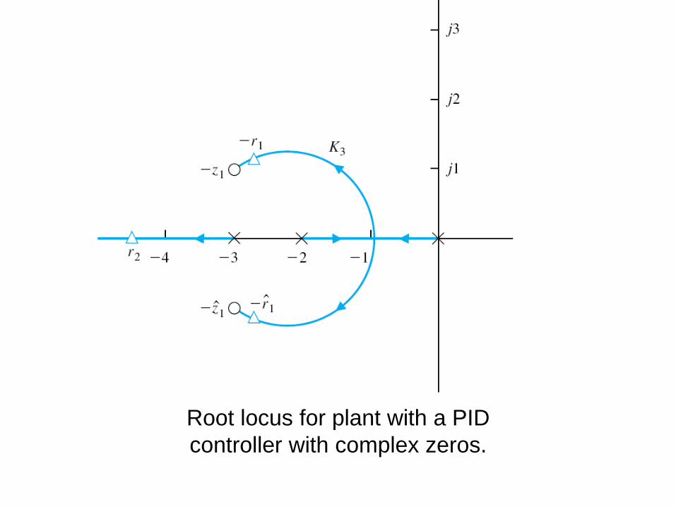
Root locus for plant with a PID
controller with complex zeros.

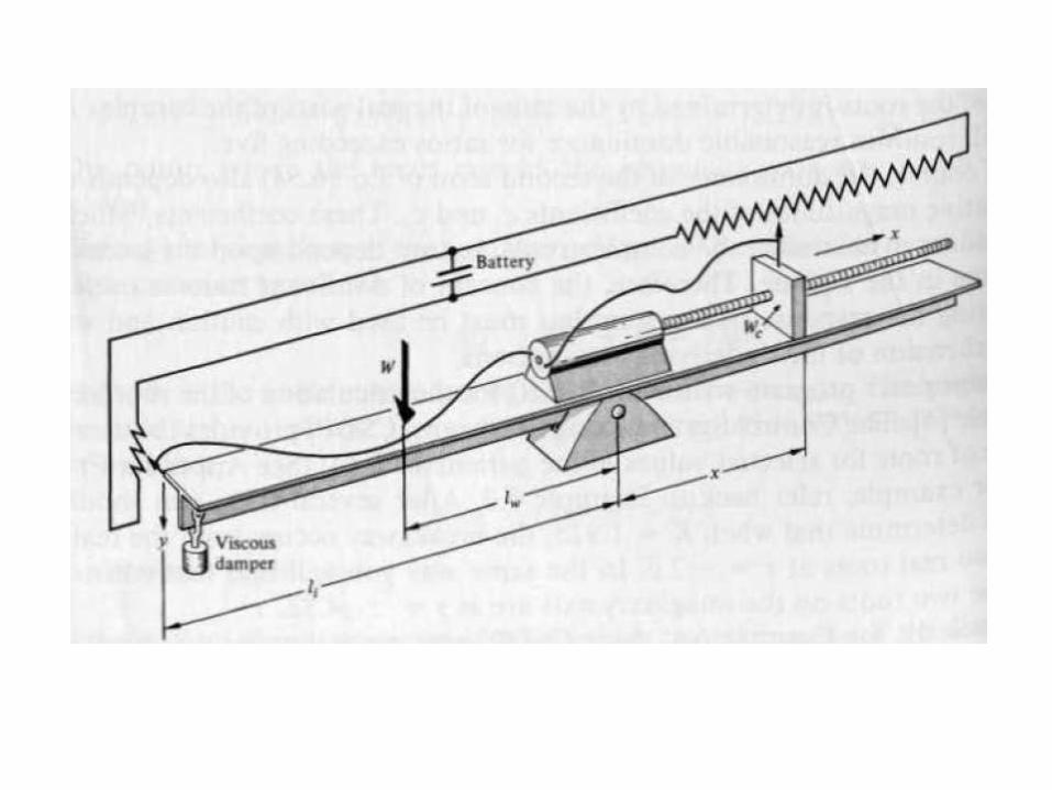
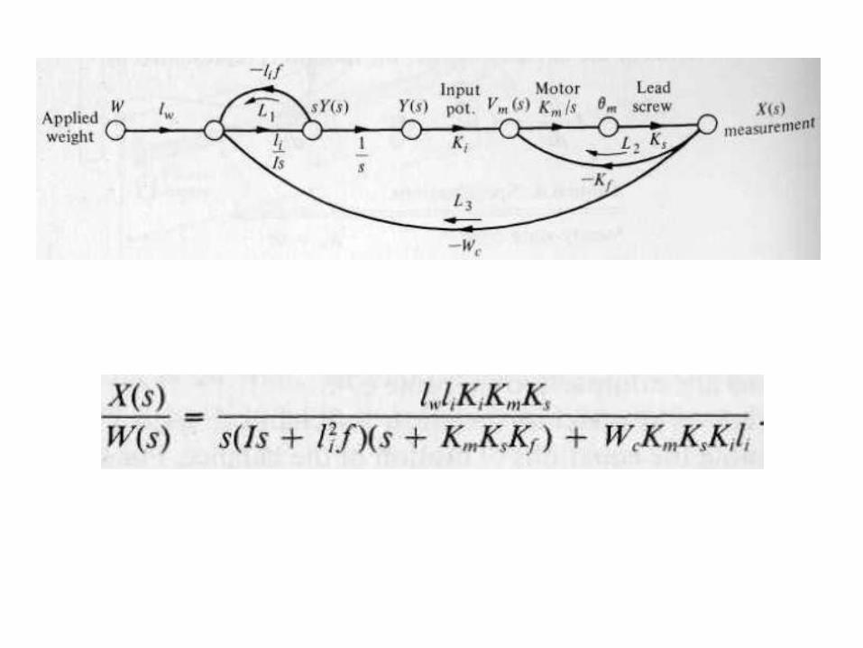
Laser manipulator control system.
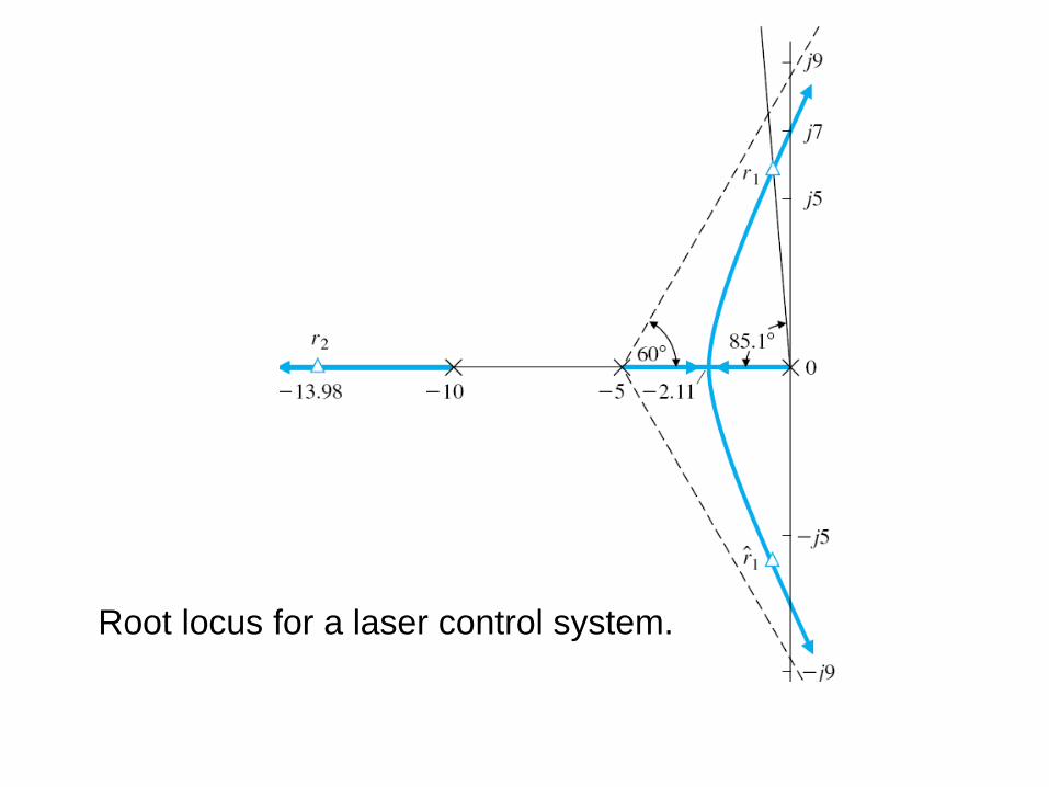
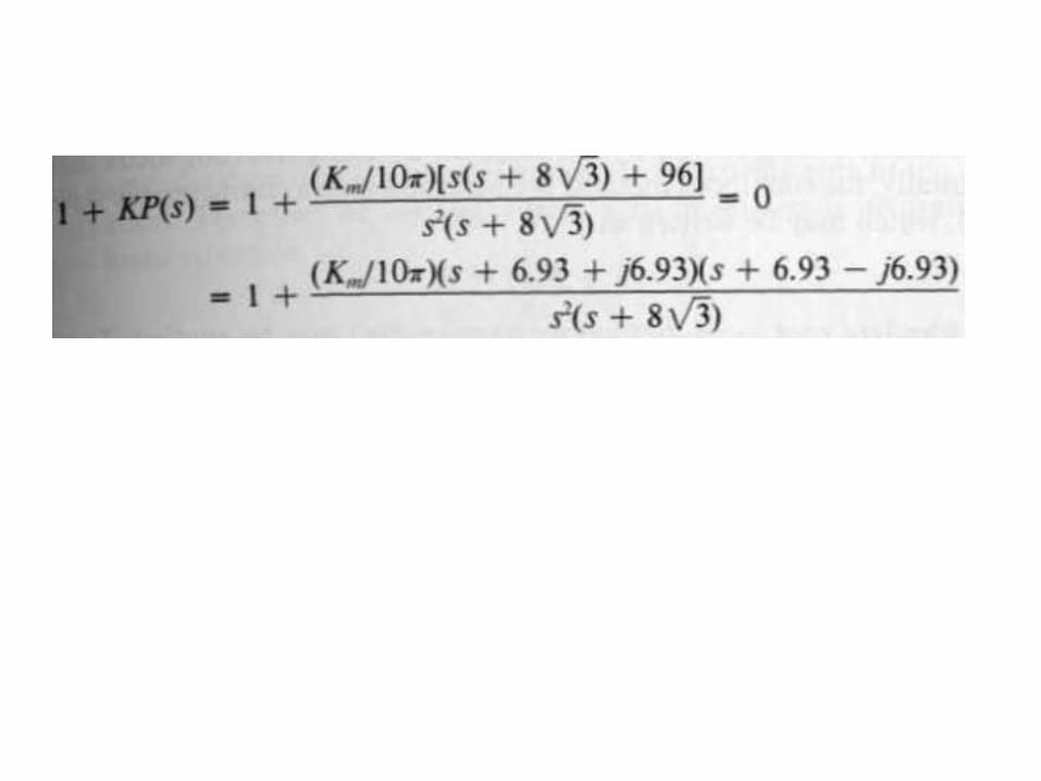
Root locus for a laser control system.
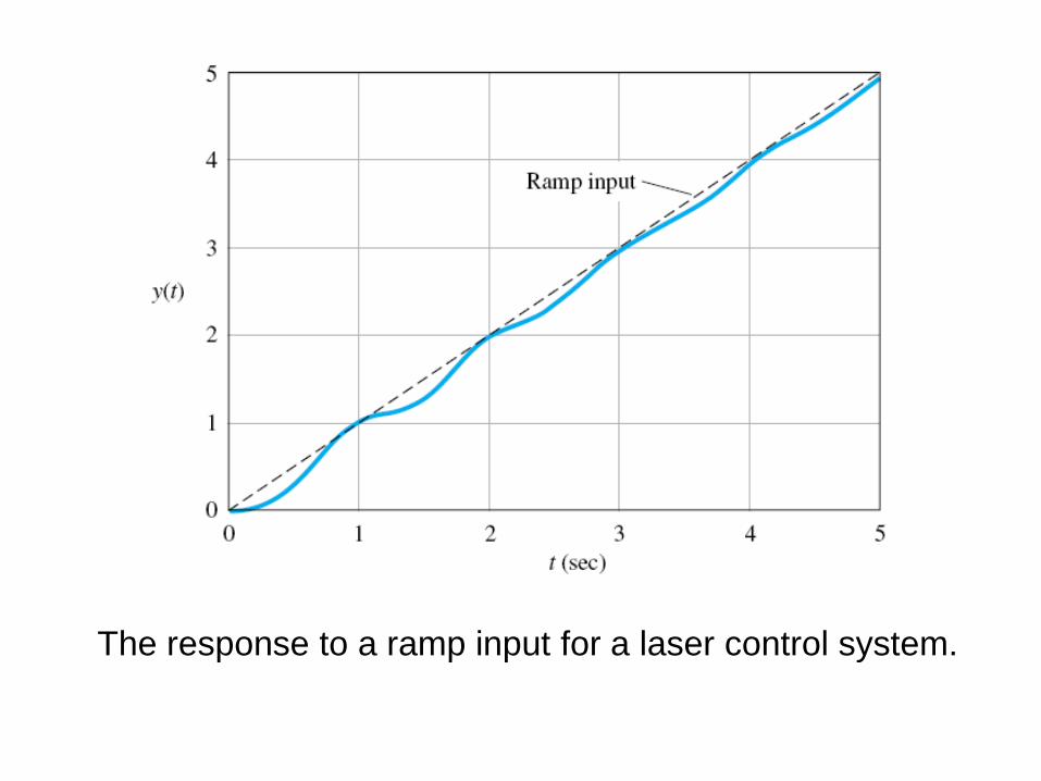
The response to a ramp input for a laser control system.

Proposed configuration for control of the lightweight
robot arm.
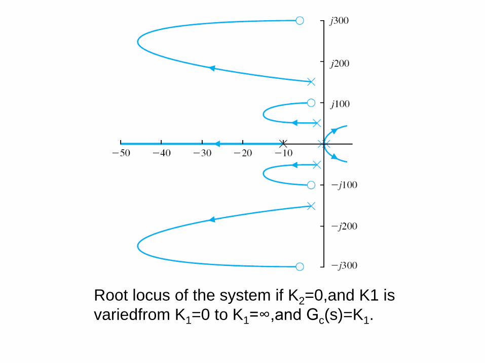
Root locus of the system if K2=0,and K1 is
variedfrom K1=0 to K1=∞,and Gc(s)=K1.
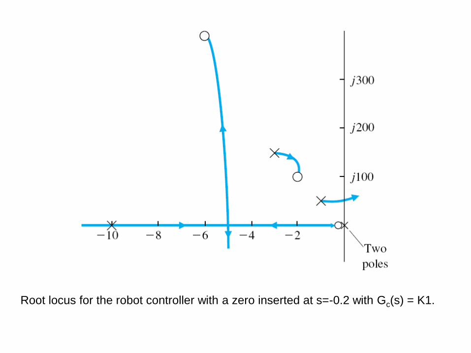
Root locus for the robot controller with a zero inserted at s=-0.2 with Gc(s) = K1.

Using the rlocus function.
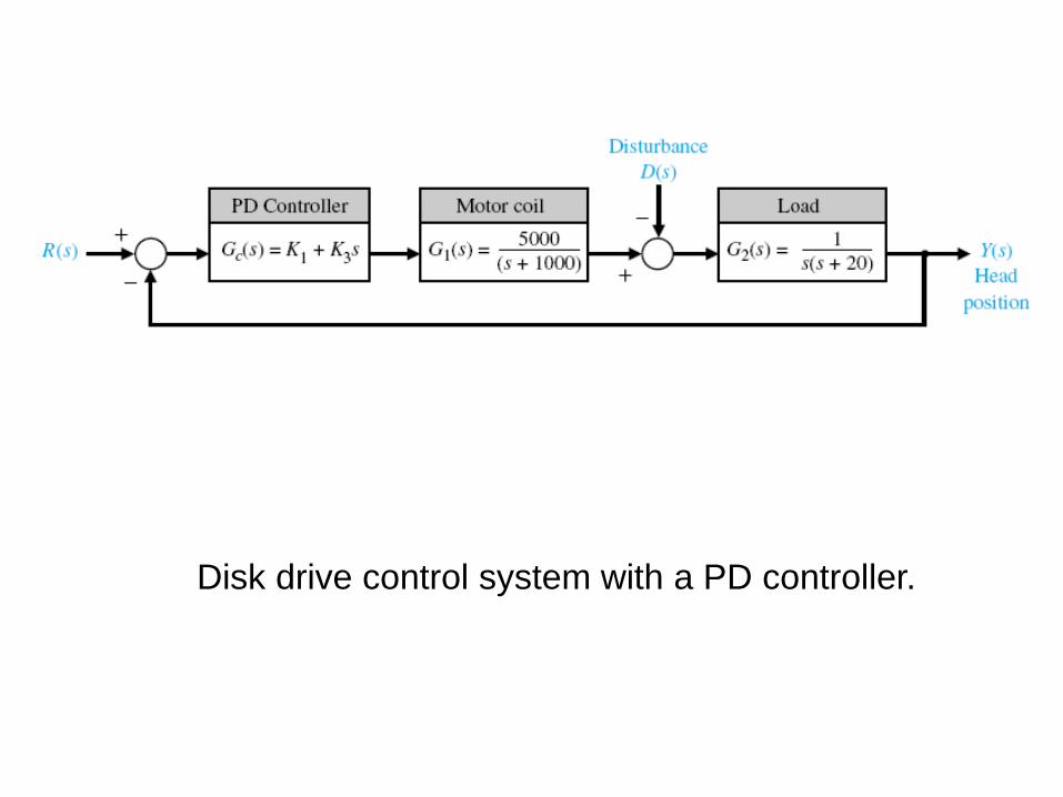
Disk drive control system with a PD controller.
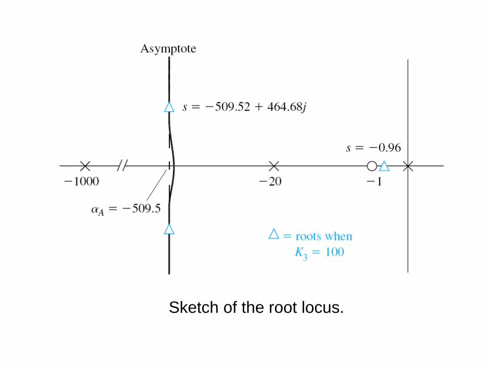
Sketch of the root locus.
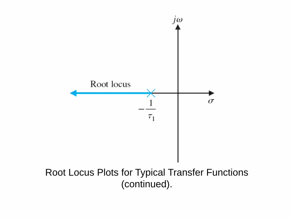
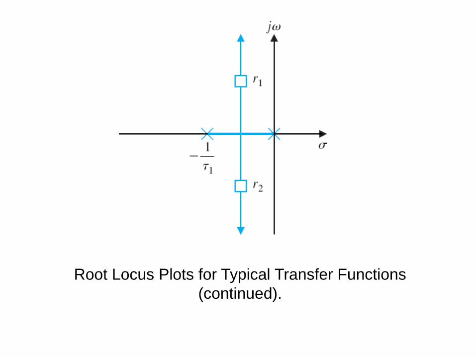
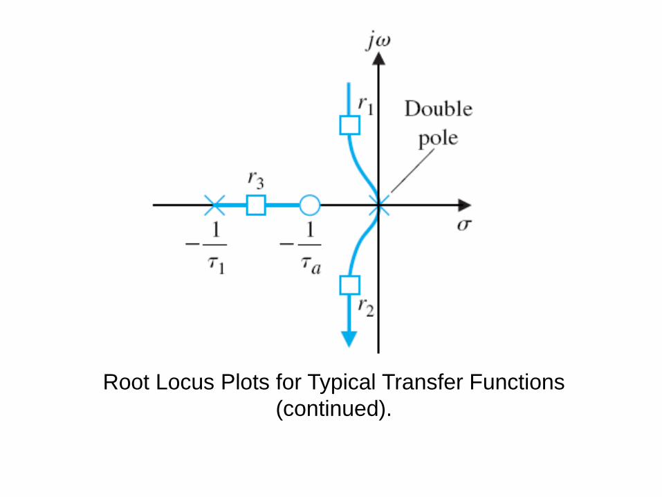
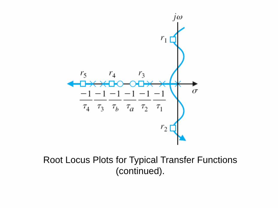
Root Locus Plots for Typical Transfer Functions
(continued).
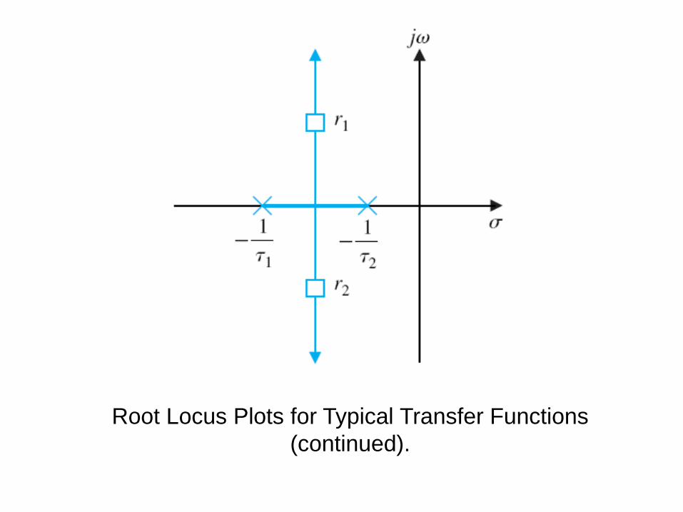
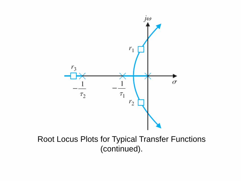
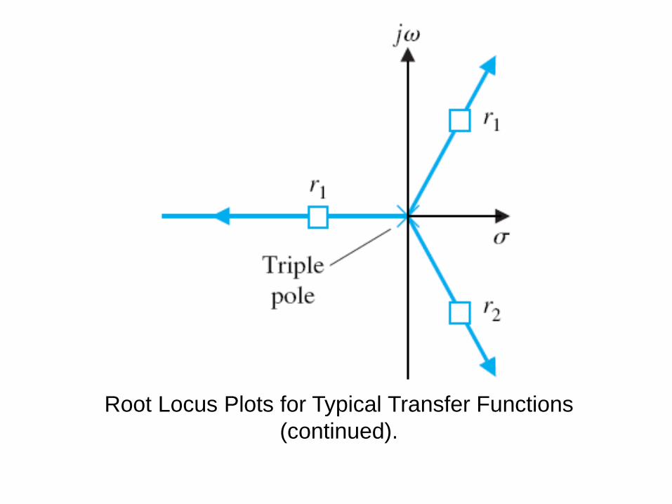
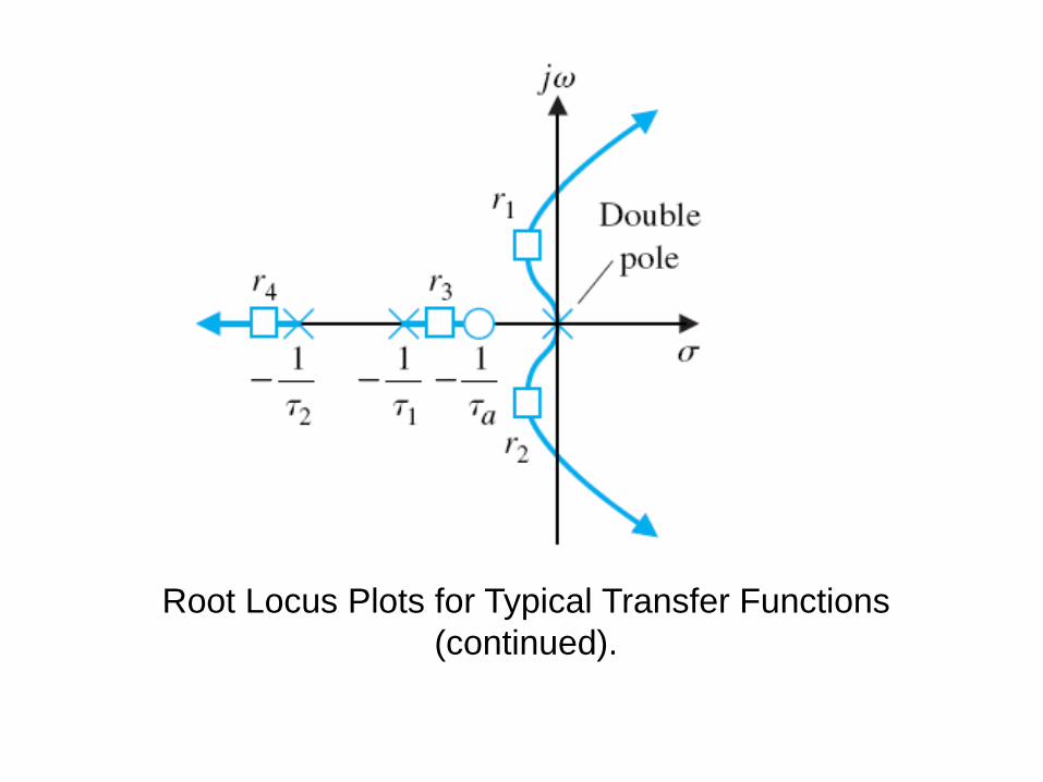
Root Locus Plots for Typical Transfer Functions
(continued).
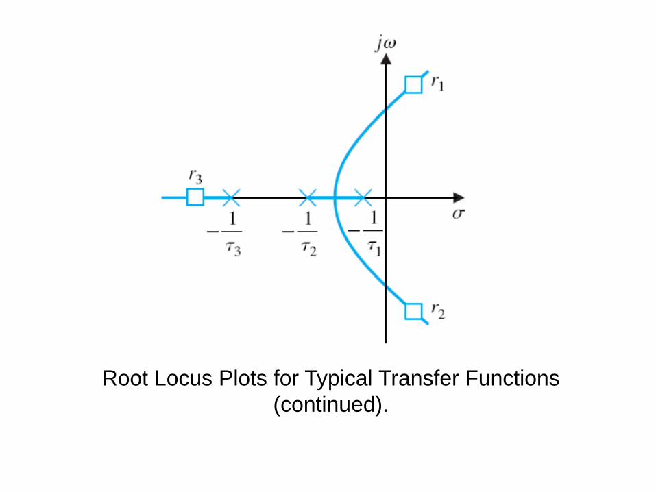
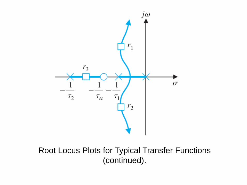
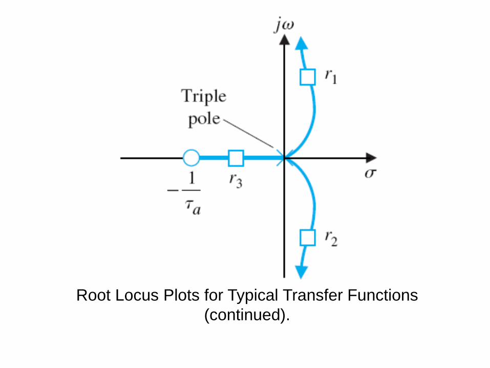
Root Locus Plots for Typical Transfer Functions
(continued).
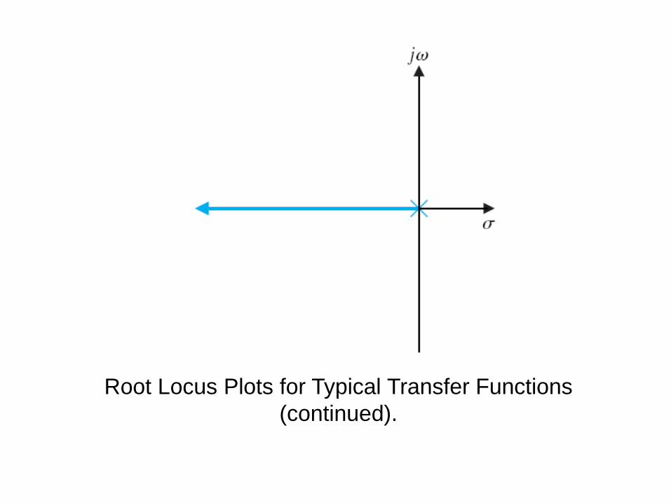
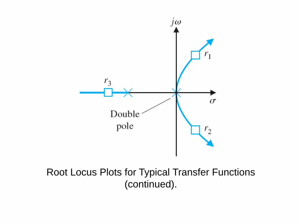
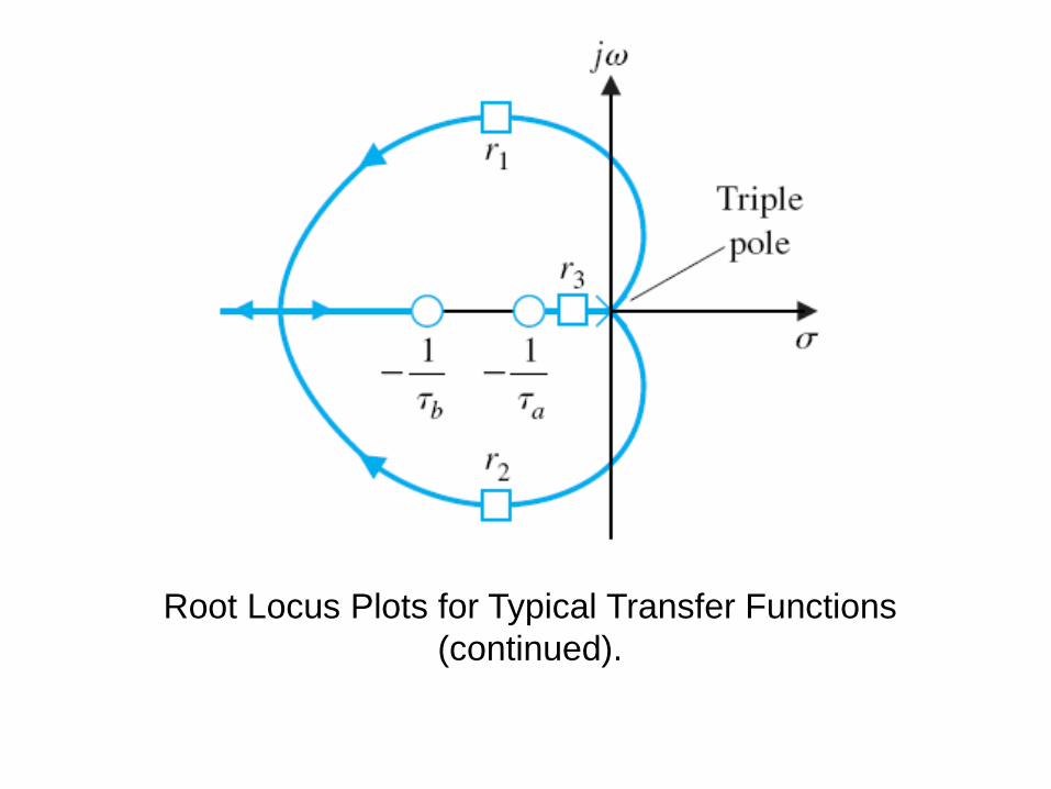
Root Locus Plots for Typical Transfer Functions
(continued).
Root Locus Plots for Typical Transfer Functions
(continued).
Root Locus Plots for Typical Transfer Functions
(continued).
Root Locus Plots for Typical Transfer Functions
(continued).

Root Locus Plots for Typical Transfer Functions
(continued).
Root Locus Plots for Typical Transfer Functions
(continued).
Root Locus Plots for Typical Transfer Functions
(continued).
Root Locus Plots for Typical Transfer Functions
(continued).
Root Locus Plots for Typical Transfer Functions
(continued).
Root Locus Plots for Typical Transfer Functions
(continued).
Root Locus Plots for Typical Transfer Functions
(continued).
Root Locus Plots for Typical Transfer Functions
(continued).


