ros based control of a 7- dof robot arm for...
TRANSCRIPT

ROS based Control of a 7-DoF Robot Arm for BMI
Reporter:Zhu Xiaoxiao
Date:2017.1.27

Self-introduction
• I am a post-doc in the Prof. Cao Qixin’s Lab in Shanghai Jiao Tong University (SJTU). The main research areas are machine vision, modularity technology and robot localization.
• Researched in the Prof. Yokoyi’s Lab from 2016.7.1~2017.1.31. The research project is an automatic Pick & Place robot arm for the BMI system.
Global Alliance Lab (GAL)

Contents
1. Introduction of Robotics Institute of SJTU and Prof. Cao’s Lab
2. Introduction of ROS
3. The development of the BMI robot arm system

China
Shanghai
31 °15'0“ N121°35'0“ E

Shanghai
Luwancampus
Minhangcampus
Fahuacampus
Qibaocampus
Xuhuicampus Zhangjiang
campus


18
96
19
35
19
87
20
06
The oldest gateZi qi dong lai
gateSiyuan gate Kaixuan gate

Today SJTU has 62 undergraduate programs covering 9 major disciplines: economics, law, literature, science, engineering, agriculture, medicine, management and arts.
By December 2015, SJTU has had 29 schools/departments, 25 dir-ectly-affiliated institutions, 13 affiliated hospitals, with 16,188 undergraduates and 20,347 postgraduates (13,841master degree candidates and 6,506 doctorate degree candidates),2,134 overseas students.
Up to 2015, SJTU led the country for the 6th consecutive year in terms of both the project number and the amount of money issued by National Natural Science Foundation of China, ranked second in sponsored research grants. The total number of SCI-cited papers from 2005 to 2014 reaches 35,488, with 308,723 times of citation, ranking the second in China.

Robotics Institute of
SJTU was established in
1985(its predecessor
was Robot Laboratory
established in 1979).
One of the earliest
robotics professional
research organization in
China. The existing 30
teachers , about 60
PhD students, more
than 50 master students.

Prof. Ichiro Kato, the father of Japanese humanoid robot, is our honorary director of the Institute during his lifetime.

Former Prime Minister Zhu Rongji in
Shanghai watched "Shanghai No. 1"
Performance, on "the introduction of
digestion Exhibition"
Former President Jiang Zemin was
watching the performance of "Shanghai
No. 1" on the conference of major
science and technology
Shanghai No. 1 is the China 's first teaching-and-replay robot

12
EOD robotFire robot
Electric cleaningrobot
Cooking robot
Four legged robot
Cable robotWall climbing robot
Researching a lot kind of robots

Get the Ph.D. in Agricultural Mechanical Engineering, Kagoshima University, Japan. And then teaching in SJTU from 1998. He is the executive deputy director of the Institute of Robotics and the director of the Institute of Biomedical Manufacturing and Life Quality Engineering.
Published more than 70 SCI/EI journal papers, obtained 90 Chinese patents, and 4 Chinese academic awards.
Prof. Cao’s Lab

Precision seeding machine
Harvest measurementsystem
Fruit sortor based onvisual inspection
Robots for Agricultural
Auto plantingsystem

Prof. cao, guided students to participate in the NHK 1998 ROBOCON competition in Japan won the mayor Award. And he organized the first china’s robot football competition in 2002. Since 2003, he began as the CCTV National College robot contest evaluation expert

Service robot and special robot
Flute robot
Painting robotLunar rover
Performing robot Toy robotOil pipeline
inspection robot
Educational robot

Service robot and special robot

Industrial robot

Medical robots
Spinal drilling robot
Working assistant robot
Minimally invasive surgery robot

Robolab.sjtu.edu.cn
Contents
1. Introduction of Robotics Institute of SJTU and Prof. Cao’s Lab
2. Introduction of ROS
3. The development of the BMI robot arm system

How to develop a robot system?
Robot Applications
Develpe a PR2 robot

How to develop a robot system?
Ok,I need a team.Divide the work
Body
Arm
Mobile base
Head
Sensors…
Drivers
Algorithms
System managers
Database
Applications
…

How to develop a robot system?
I need to manage the system
Structure clearRobustEasy management ExtendableEasy updating
…

How to develop a robot system?
I developed a similar armReuse the design and code
Reuse
Laziness is human nature

How to develop a robot system?
Divide+Manage+Reuse+…
Divide+Manage+Reuse+…
Divide+Manage+Reuse+…
Modularity Technology
…

Robot modularity technology
• Define a standard interface.
• Provide the communication and management system.
• Provide the tools for creating,compiling,debugging and management the modules.
Middleware
framework
Data Ports
Service PortsRobot Control
Program
Robotic
Component
Function Function
Function
Function
Robotic Modular

Robot modularity technology
name orginization Used standard
OROCOSK.U. Leuven in Belgium , LAAS Toulouse in France and KTH Stockholm in Sweden, www.orocos.org/
CORBA
OrcaKTH Stockholm, orca-robotics.sourceforge.net/
Ice
ROS Willow Garage , www.ros.org/ TCPROS
OpenRTM-aist
Object Management Group (OMG) and AIST, www.openrtm.org
CORBA
Miro, UPnP Robot Middleware, ASEBA, Player / Stage, The PEIS Kernel, OriN, MARIE, RSCA, The Middleware of AWARE, Sensory Data Processing Middleware, Distributed Humanoid Robots Middleware, Layer for Incorporation, WURDE

ROS(Robot Operating System)
• The ROS is a flexible framework for writing robot software. It is a collection of tools, libraries, and conventions that aim to simplify the task of creating complex and robust robot behavior across a wide variety of robotic platforms.
• ROS is open-source and encourage collaborative robotics software development.

Introduction of ROS
Peer-to-peer graph network system Robot-oriented functionality
Tf
urdf

Introduction of ROS
Command Line Tools
3D visualizationData recording and playing back System monitor

Introduction of ROS
• Provide 2500+ function packages.
• Integrated great software
Robots Sensors

Introduction of ROS
• ROS wiki
• ROS Answer
• ROS blog
• ROSCon
Smart factory based on ROS

ROS greatly accelerating the development

Contents
1. Introduction of Robotics Institute of SJTU and Prof. Cao’s Lab
2. Introduction of ROS
3. The development of the BMI robot arm system

Background
ALS(Amyotrophic lateral sclerosis,筋萎縮性側索硬化症 )
2014 ice bucket challengeStephen William Hawking
Paralysis (麻痺) is loss of muscle function for one or more muscles. Reason: damage in the nervous system, such as, stroke, trauma with nerve injury, poliomyelitis, ALS, etc.
[wikipedia.org]

Brain Machine interface (BMI)SU: Single-unit recording ECoG: ElectrocorticographyEEG: Electroencephalography
Signal reading
Feedback:Visual, vocal, Tactile
Invasion
SU ECoG EEG
PrecisionFrequency
Sensor
commands
low
Signal Processing and transformation

Signal reading
Signal Processing and transformationFeedback:
Visual, vocal, Tactile
EEGSensor
commands
• Using EEG sensor and develop brain signal classification algorithm
• Develop a light but powerful robot arm
• Add some Automatic functions to assistant the patents
• Main task is grasping the objects on the table
Project objective

System overview

System overview
Task space
RGBD Sensor,Distance sensor
Sensor
Object Recognition,Grasping point
Search,System calibration,
Path planning
Algorithm, robot controller
Robot controllers,HW interface
Robot
System monitor
RGBD Sensor,Distance sensor
Virtual Virtual
Real world
Virtualworld
Sensor data Joint Angles
HMI system

BMI robot arm
• Basic System• Hardware design
• Vision sensor
• System calibration
• Simulated robot
• Base robot control function
• Machine vision based automatic grasping
• Control sharing with BMI system

Hardware design
• 各种参数,自由度展示
• 控制接口,位置控制
既存の超軽量ロボットアームとの比較
項目 本研究 MICO²+KG-2
制御軸数 7 6
最大リーチ[m] 0.8 0.7
本体質量[kg] 2.6 5.2
可搬質量[kg] 1.0 0.8
ハンド動作自由度
1(握り・開き)
1(握り・開き)
最大速度[m/s]
2(円接線)
0.2(直線)
本研究のアームはMICO2+KG-2と比較して,出力/重量比が2.5倍自由度数/重量比が2.3倍
ヒトの関節に対応した自由度を有する

Lightweight and powerful
ロボットアーム
Aluminum alloy
carbon fiber
3D printer PLA
A lot of lightening hole
Muti metrlal
Coupled Tendon-Driven(ワイヤ干渉駆動)特願2016-109120
ワイヤ干渉駆動
Two motor are cooperating at every time.

Parallel control of the motors最大トルク:67.0kg・cm●最高スピード:0.22s/60°
●寸法:51×32×39.5mm(突起部除く)●重量:103g(サーボホーン含む)●最大動作角度:270°●最大消費電流:6.1A●ギヤ種類:特殊アルミギヤ
+ステンレスギヤ●ケース材質:アルミ(トップ、ミドル)
ガラス入り樹脂(ボトム)●ギヤ比:362.88:1●電源電圧:HV仕様(9V~12V)
●通信規格:ICS3.5(シリアル/PWM選択式)●通信速度:115200/625000/1250000bps●初期設定:ID0/BR115200●信号レベル:TTL
SH embedded control system

Repeat accuracy testing
Test Pose Random Pose5 measures for one Pose
• 3 Poses are tested
Average(mm)
Max absoluteerror(mm)
Pose1
X 20.72833 0.16544
Y 47.34129 0.426108
z 3.725552 0.126973
Pose2
X 37.14884 0.100315
Y 53.16144 0.136713
z -3.60846 0.200365
Pose3
X 25.38503 0.184033
Y 22.46846 0.512729
z -2.37699 0.176066

Vision sensor system
• RGB-D sensor can simultaneously capture the • RGB —— color information
• D —— Depth information
Right IR Camera
color Camera
IR Projector
Left IR Camera
One frame of sensor data

Vision System calibration
, 1, 2,...i i Np
, 1, 2,...i i Nq
i i q R p t
2
1
arg min ( )N
i i
i
q R p t
1
1 N
i
iN
p p
1
1 N
i
iN
q q
'
i i p p p
'
i i q q q
2
1
arg minN
i i
i
q R p
' 'T
1
N
i i
i
H q p T H U S V
T
R V U
t q R p
SVD Decomposition
|| - ||err =0.021m
n
i iR p t q
camera
robot
R, t

Simulate robot
• Gazebo is integrated in ROSReal robotVirtual robot ≈ Physical properties
≈ Task space information≈ Sensor information= Control interface
Physical simulation Robot ControlSensor data

Basic Control functions
Joint Control Trajectory Control Cartesian Control

BMI robot arm
• Basic System
• Machine vision based automatic grasping• Object recognition
• Grasping point determining
• Arm path planning
• Demonstrating
• Control sharing with BMI system

Object Recognition
Grasping Point Search
Robot Arm Path Planning
System Calibration
Object Pose Grasp PoseSensor Data
• Roadmap of the grasp system.
0°30°10°15°0°0°0°
Machine vision based automatic grasping

Object recognition
• Detect the objects on the table
RANSAC
Sensor data
Recognized plane
Clustered point cloud
Recognizedpoint cloud
2D ICP
Euclidean clustering

Recognition result
• Run at 3.5Hz
• The object most be a Rotational symmetry with Z axis
• The Z axis most Perpendicular to the table plane
• Not use the color information

• Robust to background and Motion blur
• Running at real-time
Using CNN for object recognition
200 images for training
SSD: Single Shot MultiBox Detector (Wei Liu etc.,2016)

Object Recognition
Grasping Point Search
Robot Arm Path Planning
System Calibration
Object Pose Grasp PoseSensor Data
• Roadmap of the grasp system.
0°30°10°15°0°0°0°
Machine vision based automatic grasping

Task Space Region(TSR)(Berenson 2011)
• Continuous graspable area.
0 0
0 0
0 0
0 0
0 0
o
Bo o
o e e
e1 x
y
z
x
y
z
0
R tT
min max
min
min max
min max
min max
min max
max
o
x x
y y
z z
x x
y y
z z
B

• We use searching method to find the grasp point• Generate a lot possible grasp poses of the grasper.
• Check those pose include the pre-grasp pose with Inverse Kinematic, collision etc.
• Compute a score for every possible grasp pose.
Grasping point searching
Pre-Grasp Point
Pose generate Checking
IK?
?Scoreing
𝜃
Score = 2 ∗ 𝑐𝑜𝑠𝜃, 𝑖𝑓 𝜃 > 0𝑐𝑜𝑠𝜃 , 𝑖𝑓 𝜃 < 0

Grasping point searching
Candidates of grasping pose • This method is stable
• By using parallel computing the search speed is acceptable
• Not work well for objects with complex shape

Deep learning based grasping point computing
• features:• 1.For different objects in high clutter grasping
• 2.No human demonstration, No human labeling
• 3.Suitable for different size of gripper. No retraining
• 4.Better for known objects; Suitable for unknown objects.
• 5.Can be combined with object detection
scan the scene sample the grasps find the best grasps
3D object library
get the point cloud
between each grasp
sample the grasps train CNN
whether it is a force
closure grasp
2
predict
off-line
on-line

Object Recognition
Grasping Point Search
Robot Arm Path Planning
System Calibration
Object Pose Grasp PoseSensor Data
• Roadmap of the grasp system.
0°30°10°15°0°0°0°
Machine vision based automatic grasping
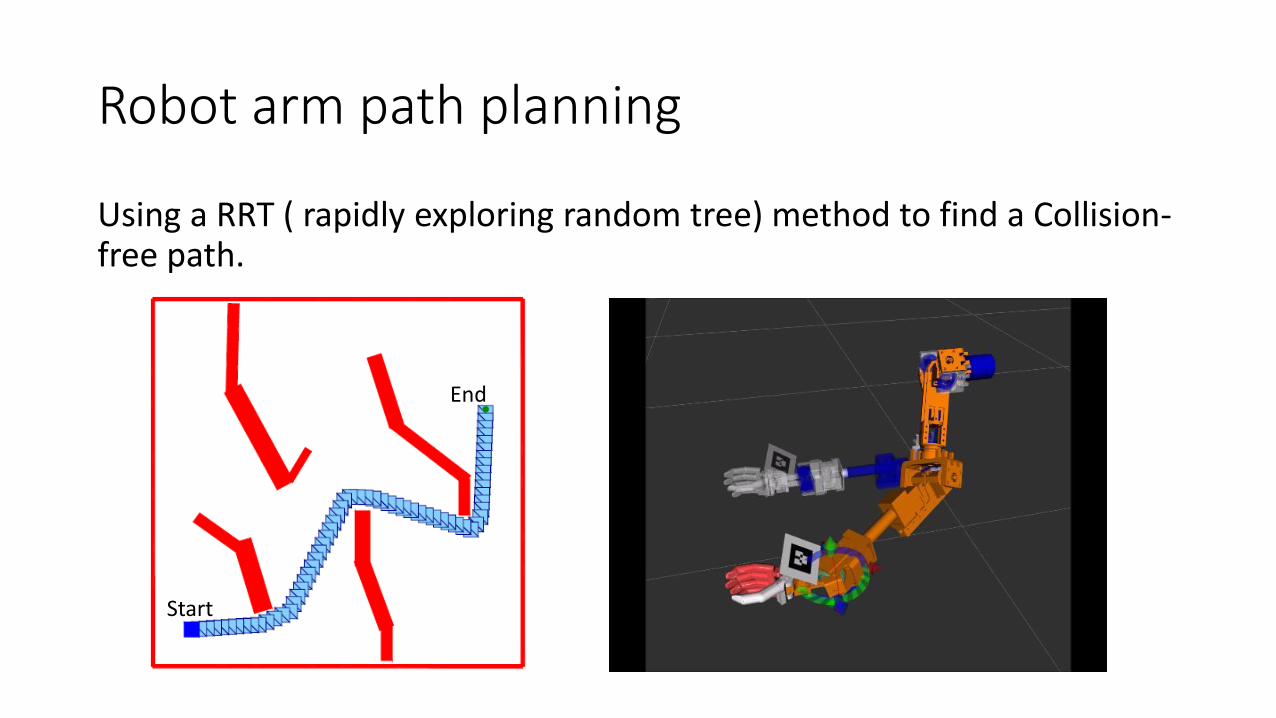
Robot arm path planning
Using a RRT ( rapidly exploring random tree) method to find a Collision-free path.
Start
End

Simulation experiment

Real robot experiment

BMI robot arm
• Basic System
• Machine vision based automatic grasping
• Control sharing with BMI system• Strategy
• Experiment

RGB-D Camera
2値制御
4値制御
物体
自律制御
A
B
BMI:Robot control
自律制御:物体認識, 障害物回避,経路・軌道計画, 把持姿勢探索,物体の把持・保持・放す
Init
Move(No
object)
GraspPlace
Start
End
Move(Object)
2値制御
4値制御
4値制御
自律制御
2値制御
自律制御
自律制御
• Using state switching such that either the BMI user or the robotic system had control during specific phases
• A Finite state machine system is used.
Finite state machine
Sharing control with BMI system

BMI grasping experiment
• SSVEP is used for BMI system
•10 tests are all successful and the average grasping time is 1 mins

conclusion
• A light but powerful robot arm is designed. The robot arm has a similar DOF configuration and work space with human. The repeat precision is high.
• A vision based automatic grasping system is developed, which has good stability for special grasping task. More intelligent function is under developing.
• A Finite State Machine system is used to communication with the BMI.
• The robot control software is based on ROS.

Thank you for your attention!