rosemount 3051s series pressure transmitter with wireless
TRANSCRIPT
Quick Installation Guide00825-0100-4802, Rev BA
June 2007 Rosemount 3051S Wireless
Rosemount 3051S Series Pressure Transmitter with
Wireless Enabled HART®
Solutions
Rosemount 3051SF Series Flowmeter Transmitter
with Wireless Enabled HART®
Solutions
4802 Rev BA.fm Page 1 Friday, June 8, 2007 1:58 PM
Pr .
Step 1: Mount the Transmitter
Step 2: Connect the Battery
Step 3: Trim the Transmitter
Step 4: Verify Operation
Step 5: Reference Information
Product Certifications
Start
End
oduct Discontinued. Click here for the new WirelessHART document
www.rosemount.com
¢00825-0100-4809[¤
Quick Installation Guide00825-0100-4802, Rev BA
June 2007Rosemount 3051S Wireless
4802 Rev BA.fm Page 2 Friday, June 8, 2007 1:58 PM
Pr .
2
© 2007 Rosemount Inc. All rights reserved. All marks property of owner. Rosemount and the Rosemount logotype are registered trademarks of Rosemount Inc.
Rosemount Inc.8200 Market BoulevardChanhassen, MN USA 55317T (US) (800) 999-9307T (Intnl) (952) 906-8888F (952) 949-7001
Emerson Process Management GmbH & Co. OHGArgelsrieder Feld 382234 WesslingGermanyT 49 (8153) 9390, F49 (8153) 939172
Emerson Process ManagementAsia Pacific Private Limited1 Pandan CrescentSingapore 128461T (65) 6777 8211F (65) 6777 0947/65 6777 0743
Beijing Rosemount Far East Instrument Co., LimitedNo. 6 North Street, Hepingli, Dong Cheng DistrictBeijing 100013, ChinaT (86) (10) 6428 2233F (86) (10) 6422 8586
IMPORTANT NOTICE
This installation guide provides basic guidelines for Rosemount 3051S Wireless Transmitters (reference manual document number 00809-0100-4802). It does not provide instructions for diagnostics, maintenance, service, or troubleshooting. Refer to the Rosemount 3051S Wireless reference manual (document number 00809-0100-4802) for more instruction. The manual and this QIG are also available electronically on www.rosemount.com.
WARNING
Explosions could result in death or serious injury:
Installation of this transmitter in an explosive environment must be in accordance with the appropriate local, national, and international standards, codes, and practices. Please review the product certifications section for any restrictions associated with a safe installation.
• Before connecting a 375 Field Communicator in an explosive atmosphere, ensure the instruments are installed in accordance with intrinsically safe or non-incendive field wiring practices.
Process leaks may cause harm or result in death. • Install and tighten process connectors before applying pressure.
Electrical shock can result in death or serious injury.• Avoid contact with the leads and terminals. High voltage that may be present on leads can cause
electrical shock.
IMPORTANT NOTICE
The Rosemount 3051S and all other wireless devices should be installed only after the 1420 Wireless Gateway has been installed and is functioning properly. Wireless devices should also be powered up in order of proximity from the 1420 Wireless Gateway, beginning with the closest. This will result in a simpler and faster network installation.
IMPORTANT NOTICE
Shipping considerations for wireless products (Lithium Batteries):
The unit was shipped to you without the battery installed. Please remove the battery pack prior to shipping the unit.
Primary lithium batteries are regulated in transportation by the U. S. Department of Transportation, and are also covered by IATA (International Air Transport Association), ICAO (International Civil Aviation Organization), and ARD (European Ground Transportation of Dangerous Goods). It is the responsibility of the shipper to ensure compliance with these or any other local requirements. Please consult current regulations and requirements before shipping.
oduct Discontinued. Click here for the new WirelessHART document
Quick Installation Guide00825-0100-4802, Rev BA
June 2007 Rosemount 3051S Wireless
4802 Rev BA.fm Page 3 Friday, June 8, 2007 1:58 PM
Pr .
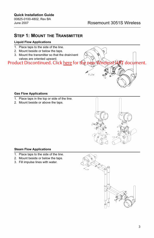
STEP 1: MOUNT THE TRANSMITTER
Liquid Flow Applications
1. Place taps to the side of the line.
2. Mount beside or below the taps.
3. Mount the transmitter so that the drain/vent
valves are oriented upward.
Gas Flow Applications
1. Place taps in the top or side of the line.
2. Mount beside or above the taps.
Steam Flow Applications
1. Place taps to the side of the line.
2. Mount beside or below the taps.
3. Fill impulse lines with water.
oduct Discontinued. Click here for the new WirelessHART document
3
Quick Installation Guide00825-0100-4802, Rev BA
June 2007Rosemount 3051S Wireless
4802 Rev BA.fm Page 4 Friday, June 8, 2007 1:58 PM
Pr .
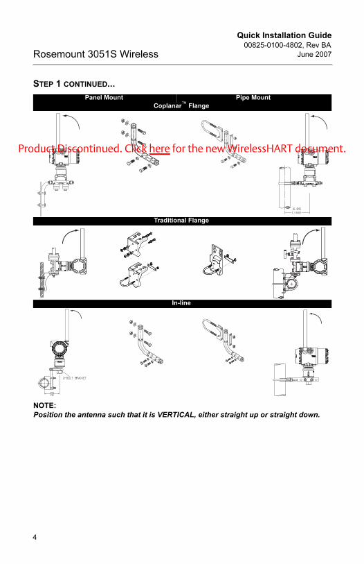
STEP 1 CONTINUED...
NOTE:
Position the antenna such that it is VERTICAL, either straight up or straight down.
Panel Mount Pipe Mount
Coplanar™ Flange
Traditional Flange
In-line
oduct Discontinued. Click here for the new WirelessHART document
4
Quick Installation Guide00825-0100-4802, Rev BA
June 2007 Rosemount 3051S Wireless
4802 Rev BA.fm Page 5 Friday, June 8, 2007 1:58 PM
Pr .
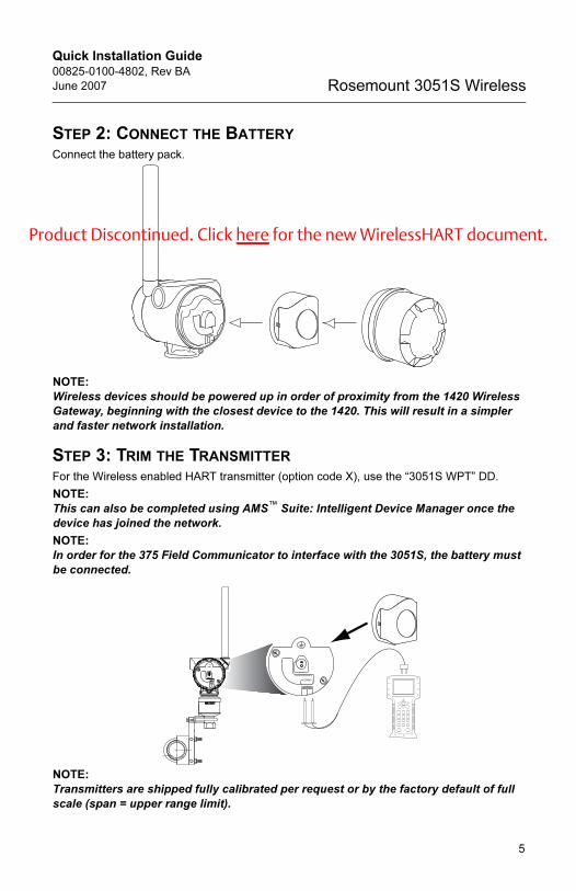
STEP 2: CONNECT THE BATTERY
Connect the battery pack.
NOTE:
Wireless devices should be powered up in order of proximity from the 1420 Wireless
Gateway, beginning with the closest device to the 1420. This will result in a simpler
and faster network installation.
STEP 3: TRIM THE TRANSMITTER
For the Wireless enabled HART transmitter (option code X), use the “3051S WPT” DD.
NOTE:
This can also be completed using AMS™ Suite: Intelligent Device Manager once the
device has joined the network.
NOTE:
In order for the 375 Field Communicator to interface with the 3051S, the battery must
be connected.
NOTE:
Transmitters are shipped fully calibrated per request or by the factory default of full
scale (span = upper range limit).
COMM
P/N 00753-9200-0010
COMMCOMM
P/N 00753-9200-0010P/N 00753-9200-0010
oduct Discontinued. Click here for the new WirelessHART document
5

Quick Installation Guide00825-0100-4802, Rev BA
June 2007Rosemount 3051S Wireless
4802 Rev BA.fm Page 6 Friday, June 8, 2007 1:58 PM
Pr .
STEP 3 CONTINUED...
Zero Trim
A zero trim is a single-point adjustment used for compensating mounting position and line
pressure effects. When performing a zero trim, ensure that the equalizing valve is open and
all wet legs are filled to the correct level.
If zero offset is less than 3% of true zero, follow the “Using the 375 Field Communicator”
instructions below to perform a zero trim. If zero offset is greater than 3%, see the 3051S
Reference Manual (document number 00809-0100-4801) to perform a rerange using the
375 Field Communicator.
Using the 375 Field Communicator
Close the Housing
Close the housing cover and tighten to safety specification. Always ensure a proper seal by
installing the electronics housing covers so that metal contacts metal, but do not over
tighten.
HART Fast Keys Steps
1, 2, 2, 2, 1 1. Equalize or vent the transmitter and connect HART communicator.2. At the menu, input the HART Fast Key sequence.
3. Follow the commands to perform a zero trim.
oduct Discontinued. Click here for the new WirelessHART document
6

Quick Installation Guide00825-0100-4802, Rev BA
June 2007 Rosemount 3051S Wireless
4802 Rev BA.fm Page 7 Friday, June 8, 2007 1:58 PM
Pr .
STEP 4: VERIFY OPERATION
Operation can be verified in four locations: at the device via the LCD, by using the 375 Field
Communicator, at the Gateway via the 1420 Wireless Gateway’s integrated web server, or
via AMS™ Suite: Intelligent Device Manager.
Local Display
The LCD will display the PV value at the same rate as the transmit rate, but no faster than
once per minute. Refer to the Rosemount 3051S Wireless manual for error codes and other
LCD messages. Press the Diagnostic button to display the TAG, Device ID, Network ID,
Network Join Status and Device Status screens.
375 Field Communicator
For the Wireless enabled HART transmitter (option code X), use the “3051S WPT” DD.
Figure 1. 375 Field Communicator Connections
1420 Wireless Gateway
In the 1420’s integrated web server, navigate to the Explorer>Status page. This page will
show whether the device has joined the network and if it is communicating properly.
NOTE:
It may take several minutes for the device to join the network.
Searching for Network Joining Network Connected with 1 Parent
Connected with 2 Parents
Function Key Sequence Menu Items
Network 1, 4, 3, 1 Smart Power, Network ID, Set Join Key, Radio State
n e t w k
a - s r c h
n e t w k
j o i n g
n e t w k
1 p a r n t
n e t w k
2 p a r n t
COMM
P/N 00753-9200-0010
COMMCOMM
P/N 00753-9200-0010P/N 00753-9200-0010
oduct Discontinued. Click here for the new WirelessHART document
7
Quick Installation Guide00825-0100-4802, Rev BA
June 2007Rosemount 3051S Wireless
4802 Rev BA.fm Page 8 Friday, June 8, 2007 1:58 PM
Pr .
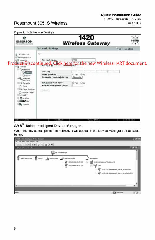
Figure 2. 1420 Network Settings
AMS™ Suite: Intelligent Device Manager
When the device has joined the network, it will appear in the Device Manager as illustrated
below.
oduct Discontinued. Click here for the new WirelessHART document
8
Quick Installation Guide00825-0100-4802, Rev BA
June 2007 Rosemount 3051S Wireless
4802 Rev BA.fm Page 9 Friday, June 8, 2007 1:58 PM
Pr .
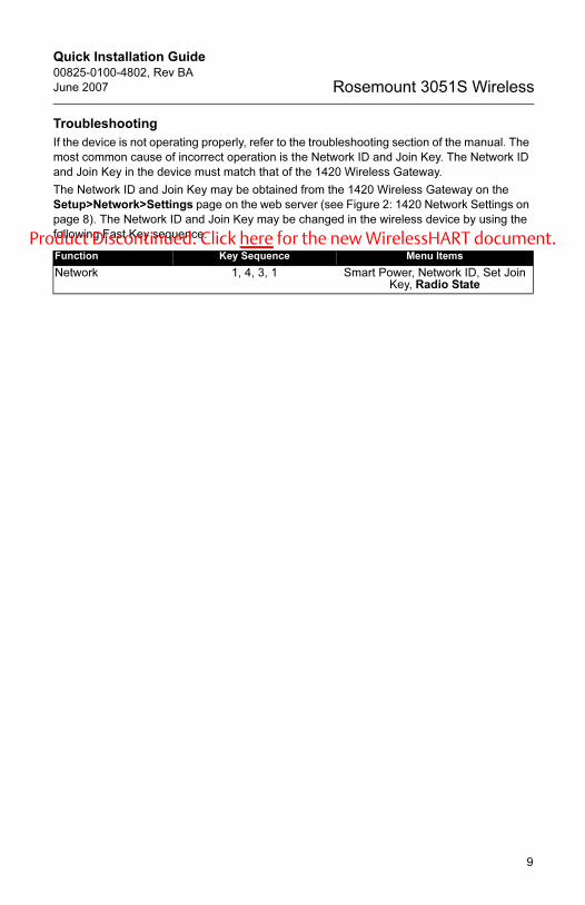
Troubleshooting
If the device is not operating properly, refer to the troubleshooting section of the manual. The
most common cause of incorrect operation is the Network ID and Join Key. The Network ID
and Join Key in the device must match that of the 1420 Wireless Gateway.
The Network ID and Join Key may be obtained from the 1420 Wireless Gateway on the
Setup>Network>Settings page on the web server (see Figure 2: 1420 Network Settings on
page 8). The Network ID and Join Key may be changed in the wireless device by using the
following Fast Key sequence.
Function Key Sequence Menu Items
Network 1, 4, 3, 1 Smart Power, Network ID, Set Join Key, Radio State
oduct Discontinued. Click here for the new WirelessHART document
9

Quick Installation Guide00825-0100-4802, Rev BA
June 2007Rosemount 3051S Wireless
4802 Rev BA.fm Page 10 Friday, June 8, 2007 1:58 PM
Pr .
STEP 5: REFERENCE INFORMATION
Figure 3. Terminal Diagram
NOTE:
In order to communicate with a 375 Field Communicator, the device must be powered
by connecting the battery pack.
Table 1. HART Fast Key Sequence
Figure 4. 375 Field Communicator Connections
Function Key Sequence Menu Items
Device Info 1, 3, 4 Date, Descriptor, Message, Write Protect, Model, Model Number I, II, III
Process Variables 1, 1 Pressure, % Range, Snsr Temp, Supply Voltage, PV is
Sensor Trim 1, 2, 2, 2 Zero Trim, Lower Sensor Trim, Upper Sensor Trim, Calibration Type, Sensor
Trim Points
Network 1, 4, 3, 1 Smart Power, Network ID, Set Join Key, Radio State
COMM
P/N 00753-9200-0010
COMM
P/N 00753-9200-0010
COMMCOMM
P/N 00753-9200-0010P/N 00753-9200-0010
oduct Discontinued. Click here for the new WirelessHART document
10

Quick Installation Guide00825-0100-4802, Rev BA
June 2007 Rosemount 3051S Wireless
4802 Rev BA.fm Page 11 Friday, June 8, 2007 1:58 PM
Pr .
PRODUCT CERTIFICATIONS
Approved Manufacturing Locations
Rosemount Inc. — Chanhassen, Minnesota USA
Telecommunication Compliance
All wireless devices require certification to ensure that they adhere to regulations regarding
the use of the RF spectrum. Nearly every country requires this type of product certification.
Emerson is working with governmental agencies around the world to supply fully compliant
products and remove the risk of violating country directives or laws governing wireless
device usage. To see which countries our devices have received certification for use in, see
www.rosemount.com/smartwireless.
Ordinary Location Certification for FM
As standard, the transmitter has been examined and tested to determine that the design
meets basic electrical, mechanical, and fire protection requirements by FM, a nationally
recognized testing laboratory (NRTL) as accredited by the Federal Occupational Safety and
Health Administration (OSHA).
North American Certifications
Factory Mutual (FM) Approvals
I5 FM Intrinsic Safety, Non-Incendive, and Dust Ignition-proof.
Intrinsically Safe for Class I/II/III, Division 1, Groups A, B, C, D, E, F, and G.
Zone Marking: Class I, Zone 0, AEx ia llC
Temperature Codes T4 (Tamb = -50 to 70° C)
Non-Incendive for Class I, Division 2, Groups A, B, C, and D.
Dust Ignition-proof for Class II/III, Division 1, Groups E, F, and G.
Ambient temperature limits: -50 to 85° C
For use with Rosemount battery pack P/N 00753-9220-XXXX only.
Enclosure Type 4X / IP66
CSA - Canadian Standards Association
I6 CSA Intrinsic Safety
Intrinsically Safe for Class I, Division 1, Groups A, B, C, and D.
Temp Code T3C
Enclosure Type 4X / IP66
For use with Rosemount battery pack P/N 00753-9220-XXXX only.
oduct Discontinued. Click here for the new WirelessHART document
11
Quick Installation Guide00825-0100-4802, Rev BA
June 2007Rosemount 3051S Wireless
4802 Rev BA.fm Page 12 Friday, June 8, 2007 1:58 PM
Pr .
12
European Directive Information
The EC declaration of conformity for all applicable European directives for this product can
be found at www.rosemount.com. A hard copy may be obtained by contacting an Emerson
Process Management representative.
ATEX Directive (94/9/EC)
Emerson Process Management complies with the ATEX Directive.
European Pressure Equipment Directive (PED) (97/23/EC)
Models 3051S_CA4; 3051S_CD2, 3, 4, 5; (also with P9 option)
Pressure Transmitters — QS Certificate of Assessment -
EC No. PED-H-100, Module H Conformity Assessment
All other Model 3051S Pressure Transmitters
— Sound Engineering Practice
Transmitter Attachments: Diaphragm Seal - Process Flange -
Manifold — Sound Engineering Practice
Primary Elements, Flowmeter
— See appropriate Primary Element QIG
Electro Magnetic Compatibility (EMC) (2004/108/EC)
All Models: EN 50081-1: 1992; EN 50082-2:1995;
EN 61326-1:1997 + A1, A2, and A3 – Industrial
Radio and Telecommunications Terminal Equipment Directive (R&TTE)(1999/5/EC)
Emerson Process Management complies with the R&TTE Directive.
European Certifications
I1 ATEX Intrinsic Safety
Certificate No.: BAS01ATEX1303X II 1G
Ex ia IIC T4 (Ta = -60 °C to 70 °C)
IP66
1180
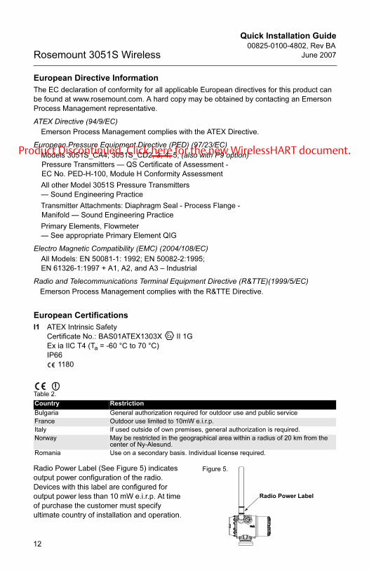
Table 2.
Country Restriction
Bulgaria General authorization required for outdoor use and public service
France Outdoor use limited to 10mW e.i.r.p.
Italy If used outside of own premises, general authorization is required.
Norway May be restricted in the geographical area within a radius of 20 km from the center of Ny-Alesund.
Romania Use on a secondary basis. Individual license required.
Radio Power Label
Figure 5. Radio Power Label (See Figure 5) indicates
output power configuration of the radio.
Devices with this label are configured for
output power less than 10 mW e.i.r.p. At time
of purchase the customer must specify
ultimate country of installation and operation.
oduct Discontinued. Click here for the new WirelessHART document