rosemount 5400 series spare part...
TRANSCRIPT
Manual Supplement00809-0200-4026, Rev AAJune 2008 Rosemount 5400 Series
Rosemount 5400 Series Spare Part Instruction
Introduction . . . . . . . . . . . . . . . . . . . . . . . . . . . . . . . . . . . . . page 1-1Safety Messages . . . . . . . . . . . . . . . . . . . . . . . . . . . . . . . . . page 1-1Overview . . . . . . . . . . . . . . . . . . . . . . . . . . . . . . . . . . . . . . . page 1-2Installation Procedure . . . . . . . . . . . . . . . . . . . . . . . . . . . . page 1-3
INTRODUCTION This instruction is a supplement to the Rosemount 5400 Series Reference Manual (Document No. 00809-0100-4026). It describes how to replace the Terminal Block and the EMC Board on a Rosemount 5400 Series transmitter.
Tools The following tools are needed:� A 60 mm wrench is used to unscrew the nut when removing the
transmitter head� A screw driver is used to disconnect the cables� Plastic bag or cloth� Wrench for removing cable glands
SAFETY MESSAGES
Explosions could result in death or serious injury:Verify that the operating environment of the transmitter is consistent with the appropriate hazardous locations certifications.
Before connecting a HART-based communicator in an explosive atmosphere, make sure the instruments in the loop are installed in accordance with intrinsically safe or non-incendive field wiring practices.
Do not remove the gauge cover in explosive atmospheres when the circuit is alive.
Failure to follow safe installation and servicing guidelines could result in death or serious injury:Make sure only qualified personnel perform the installation.
Use the equipment only as specified in the Rosemount 5400 Series Reference Manual (Document No. 00809-0100-4026) and in this manual supplement. Failure to do so may impair the protection provided by the equipment.
High voltage that may be present on leads could cause electrical shock:Avoid contact with leads and terminals.
Make sure the main power to the 5400 transmitter is off and the lines to any other external power source are disconnected or not powered while wiring the gauge.
www.rosemount.com
Manual Supplement00809-0200-4026, Rev AA
June 2008Rosemount 5400 Series
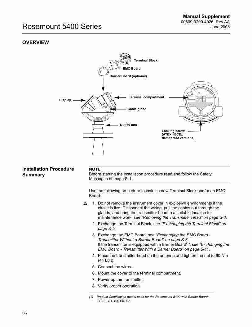
OVERVIEW
Installation Procedure Summary
NOTEBefore starting the installation procedure read and follow the Safety Messages on page S-1.
Use the following procedure to install a new Terminal Block and/or an EMC Board:
1. Do not remove the instrument cover in explosive environments if the circuit is live. Disconnect the wiring, pull the cables out through the glands, and bring the transmitter head to a suitable location for maintenance work, see �Removing the Transmitter Head� on page S-3.
2. Exchange the Terminal Block, see �Exchanging the Terminal Block� on page S-5.
3. Exchange the EMC Board, see �Exchanging the EMC Board - Transmitter Without a Barrier Board� on page S-8. If the transmitter is equipped with a Barrier Board(1), see �Exchanging the EMC Board - Transmitter With a Barrier Board� on page S-11.
4. Place the transmitter head on the antenna and tighten the nut to 60 Nm (44 Lbft).
5. Connect the wires.6. Mount the cover to the terminal compartment.7. Power up the transmitter.8. Verify proper operation.
Nut 60 mm
Terminal compartment
Cable gland
Display
Terminal Block
EMC Board
Barrier Board (optional)
Locking screw(ATEX, IECEx flameproof versions)
(1) Product Certification model code for the Rosemount 5400 with Barrier Board: E1, E3, E4, E5, E6, E7.
S-2
Manual Supplement 00809-0200-4026, Rev AAJune 2008 Rosemount 5400 Series
INSTALLATION PROCEDURE
This section describes the different steps to exchange the Terminal Block and/or the EMC Board on a Rosemount 5400 transmitter.
1. Removing the Transmitter Head section describes how to disconnect wiring and remove the transmitter head from the antenna.
2. Exchanging the Terminal Block section describes how to remove and replace the Terminal Block.
3. Exchanging the EMC Board - option 1 describes how to remove and replace the EMC Board on a Rosemount 5400 transmitter.
4. Exchanging the EMC Board - option 2 describes how to remove and replace the EMC Board on a 5400 transmitter with a Barrier Board.
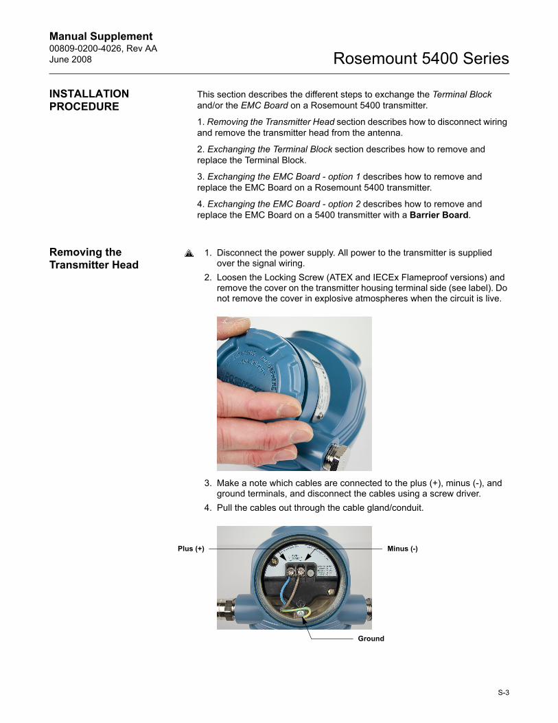
Removing the Transmitter Head
1. Disconnect the power supply. All power to the transmitter is supplied over the signal wiring.
2. Loosen the Locking Screw (ATEX and IECEx Flameproof versions) and remove the cover on the transmitter housing terminal side (see label). Do not remove the cover in explosive atmospheres when the circuit is live.
3. Make a note which cables are connected to the plus (+), minus (-), and ground terminals, and disconnect the cables using a screw driver.
4. Pull the cables out through the cable gland/conduit.
Minus (-)Plus (+)
Ground
S-3
Manual Supplement00809-0200-4026, Rev AA
June 2008Rosemount 5400 Series
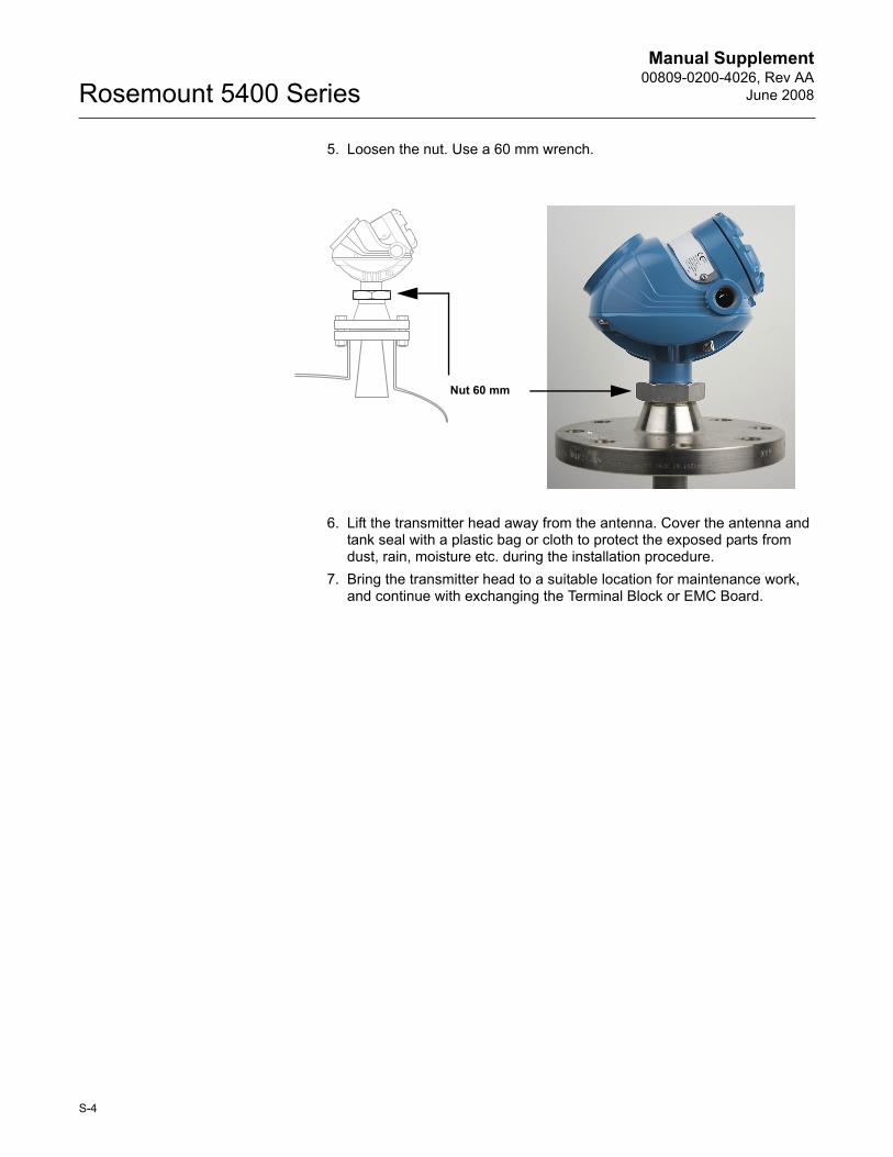
5. Loosen the nut. Use a 60 mm wrench.
6. Lift the transmitter head away from the antenna. Cover the antenna and tank seal with a plastic bag or cloth to protect the exposed parts from dust, rain, moisture etc. during the installation procedure.
7. Bring the transmitter head to a suitable location for maintenance work, and continue with exchanging the Terminal Block or EMC Board.
Nut 60 mm
S-4

Manual Supplement 00809-0200-4026, Rev AAJune 2008 Rosemount 5400 Series
Exchanging the Terminal Block
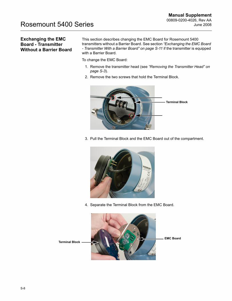
1. Remove the two screws that hold the Terminal Block.
2. Pull the Terminal Block out of the compartment.
3. Separate the Terminal Block from the EMC Board. If the transmitter is equipped with the optional Barrier Board, the Terminal Block may be separated from the EMC Board when it is pulled out of the compartment.
Terminal Block
EMC BoardTerminal Block
S-5
Manual Supplement00809-0200-4026, Rev AA
June 2008Rosemount 5400 Series
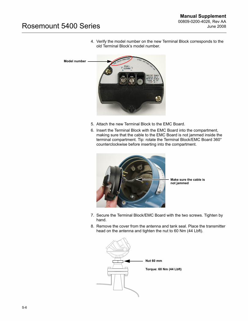
4. Verify the model number on the new Terminal Block corresponds to the old Terminal Block�s model number.
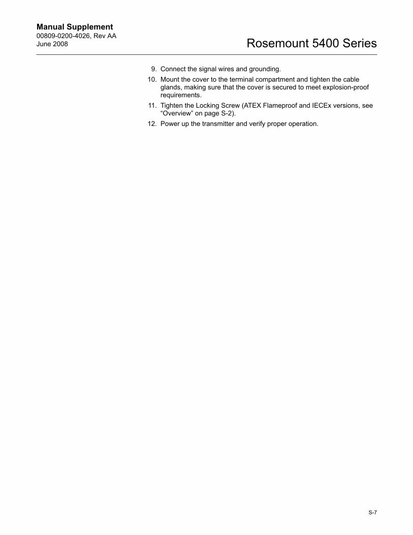
5. Attach the new Terminal Block to the EMC Board. 6. Insert the Terminal Block with the EMC Board into the compartment,
making sure that the cable to the EMC Board is not jammed inside the terminal compartment. Tip: rotate the Terminal Block/EMC Board 360° counterclockwise before inserting into the compartment.
7. Secure the Terminal Block/EMC Board with the two screws. Tighten by hand.
8. Remove the cover from the antenna and tank seal. Place the transmitter head on the antenna and tighten the nut to 60 Nm (44 Lbft).
Model number
Make sure the cable is not jammed
Nut 60 mm
Torque: 60 Nm (44 Lbft)
S-6
Manual Supplement 00809-0200-4026, Rev AAJune 2008 Rosemount 5400 Series
9. Connect the signal wires and grounding.10. Mount the cover to the terminal compartment and tighten the cable
glands, making sure that the cover is secured to meet explosion-proof requirements.
11. Tighten the Locking Screw (ATEX Flameproof and IECEx versions, see �Overview� on page S-2).
12. Power up the transmitter and verify proper operation.
S-7
Manual Supplement00809-0200-4026, Rev AA
June 2008Rosemount 5400 Series
Exchanging the EMC Board - Transmitter Without a Barrier Board
This section describes changing the EMC Board for Rosemount 5400 transmitters without a Barrier Board. See section �Exchanging the EMC Board - Transmitter With a Barrier Board� on page S-11 if the transmitter is equipped with a Barrier Board.
To change the EMC Board:
1. Remove the transmitter head (see �Removing the Transmitter Head� on page S-3).
2. Remove the two screws that hold the Terminal Block.
3. Pull the Terminal Block and the EMC Board out of the compartment.
4. Separate the Terminal Block from the EMC Board.
Terminal Block
EMC BoardTerminal Block
S-8
Manual Supplement 00809-0200-4026, Rev AAJune 2008 Rosemount 5400 Series
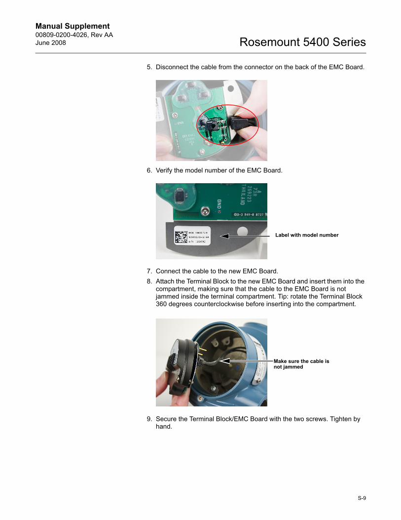
5. Disconnect the cable from the connector on the back of the EMC Board.
6. Verify the model number of the EMC Board.
7. Connect the cable to the new EMC Board.8. Attach the Terminal Block to the new EMC Board and insert them into the
compartment, making sure that the cable to the EMC Board is not jammed inside the terminal compartment. Tip: rotate the Terminal Block 360 degrees counterclockwise before inserting into the compartment.
9. Secure the Terminal Block/EMC Board with the two screws. Tighten by hand.
Label with model number
Make sure the cable is not jammed
S-9
Manual Supplement00809-0200-4026, Rev AA
June 2008Rosemount 5400 Series
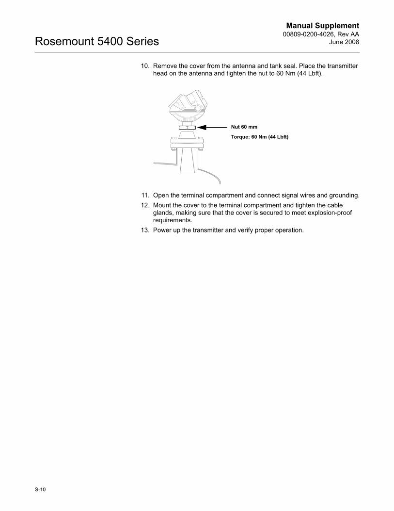
10. Remove the cover from the antenna and tank seal. Place the transmitter head on the antenna and tighten the nut to 60 Nm (44 Lbft).
11. Open the terminal compartment and connect signal wires and grounding.12. Mount the cover to the terminal compartment and tighten the cable
glands, making sure that the cover is secured to meet explosion-proof requirements.
13. Power up the transmitter and verify proper operation.
Torque: 60 Nm (44 Lbft)
Nut 60 mm
S-10
Manual Supplement 00809-0200-4026, Rev AAJune 2008 Rosemount 5400 Series
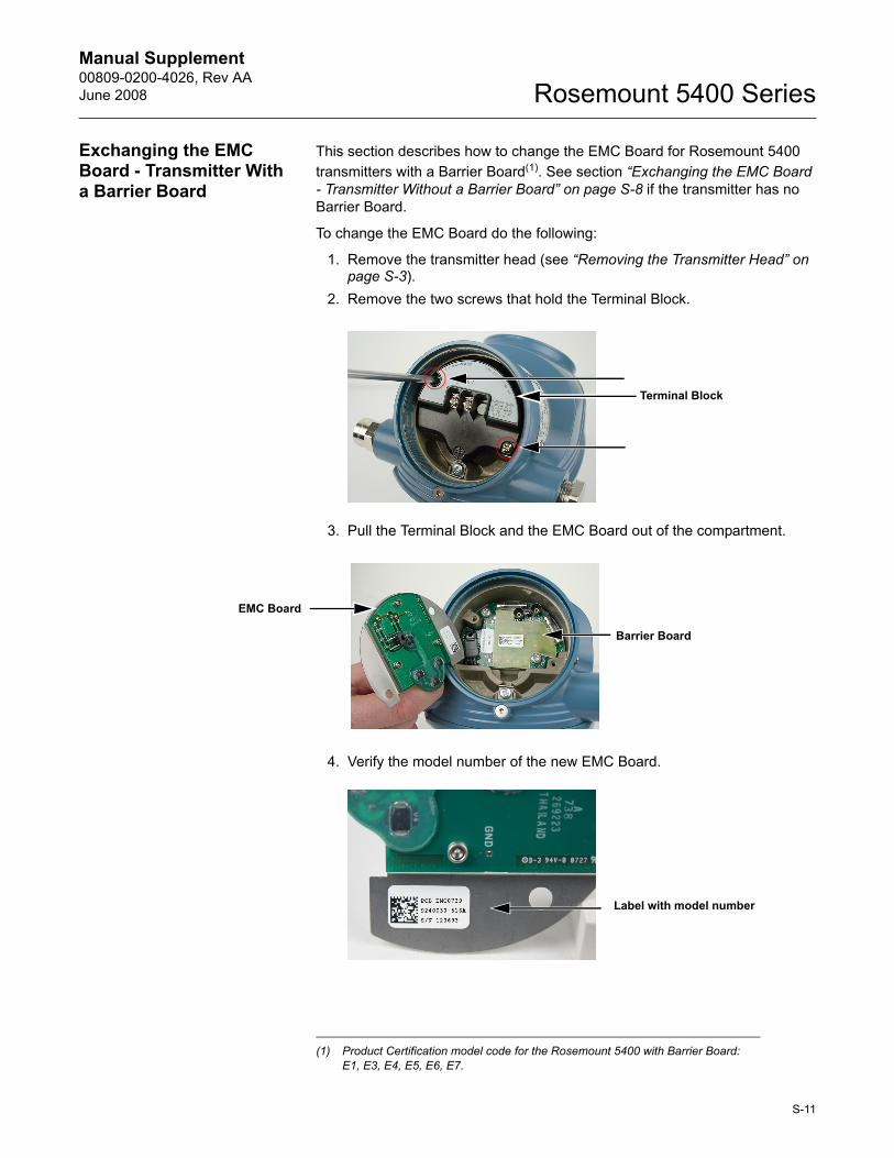
Exchanging the EMC Board - Transmitter With a Barrier Board
This section describes how to change the EMC Board for Rosemount 5400 transmitters with a Barrier Board(1). See section �Exchanging the EMC Board - Transmitter Without a Barrier Board� on page S-8 if the transmitter has no Barrier Board.
To change the EMC Board do the following:
1. Remove the transmitter head (see �Removing the Transmitter Head� on page S-3).
2. Remove the two screws that hold the Terminal Block.
3. Pull the Terminal Block and the EMC Board out of the compartment.
4. Verify the model number of the new EMC Board.
(1) Product Certification model code for the Rosemount 5400 with Barrier Board: E1, E3, E4, E5, E6, E7.
Terminal Block
EMC Board
Barrier Board
Label with model number
S-11
Manual Supplement00809-0200-4026, Rev AA
June 2008Rosemount 5400 Series
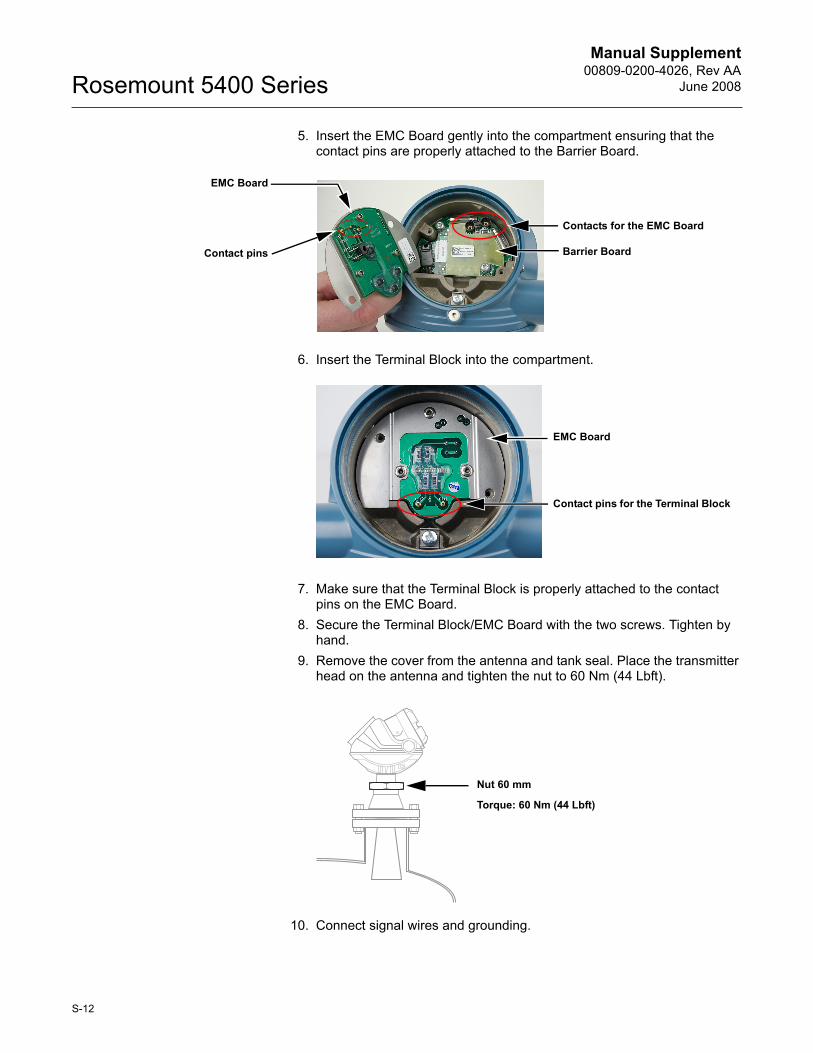
5. Insert the EMC Board gently into the compartment ensuring that the contact pins are properly attached to the Barrier Board.
6. Insert the Terminal Block into the compartment.
7. Make sure that the Terminal Block is properly attached to the contact pins on the EMC Board.
8. Secure the Terminal Block/EMC Board with the two screws. Tighten by hand.
9. Remove the cover from the antenna and tank seal. Place the transmitter head on the antenna and tighten the nut to 60 Nm (44 Lbft).
10. Connect signal wires and grounding.
EMC Board
Contact pins Barrier Board
Contacts for the EMC Board
Contact pins for the Terminal Block
EMC Board
Torque: 60 Nm (44 Lbft)
Nut 60 mm
S-12
Manual Supplement 00809-0200-4026, Rev AAJune 2008 Rosemount 5400 Series
11. Mount the cover to the terminal compartment and tighten the cable glands, making sure that the cover is secured to meet explosion-proof requirements.
12. Tighten the Locking Screw (ATEX Flameproof and IECEx versions).13. Power up the transmitter and verify proper operation.
S-13
Emerson Process Management
© 2008 Rosemount Inc. All rights reserved.
Rosemount and the Rosemount logotype are registered trademarks of Rosemount Inc.PlantWeb is a registered trademark of one of the Emerson Process Management group of companies.Teflon, VITON, and Kalrez are registered trademarks of DuPont Performance Elastomers.Asset Management Solutions is a trademark of Emerson Process Management.All other marks are the property of their respective owners.
Standard Terms and Conditions of Sale can be found at www.rosemount.com\terms_of_sale.
Manual Supplement00809-0200-4026, Rev AA
June 2008Rosemount 5400 Series
Emerson Process Management Shared Services Ltd.Heath PlaceBognor RegisWest Sussex PO22 9SHEnglandTel 44 (1243) 863121Fax 44 (1243) 867554
Emerson Process Management Asia Pacific Private Limited1 Pandan CrescentSingapore 128461Tel (65) 6777-8211Fax (65) [email protected]
Rosemount Inc.8200 Market BoulevardChanhassen, MN 55317 USAT (U.S.) 1-800-999-9307T (International) (952) 906-8888F (952) 949-7001
www.rosemount.com