rosemount
DESCRIPTION
anything you want....... need to programabale... if u ok... we will see next weekTRANSCRIPT

Product Data Sheet00813-0100-4801, Rev LA
October 2008 Rosemount 3051S Series
Rosemount 3051S Series of InstrumentationScalable Pressure, Flow, and Level Solutions
• Industry leading performance with 0.025%
accuracy
• Industry’s first %-of-reading flow transmitter
delivering a 10x performance improvement
• Industry's first installed 10-year stability
• Unprecedented reliability backed by a 12-year
limited warranty
• Scalable SuperModule® Platform provides a
foundation for integrated pressure, flow, and
level solutions
• WirelessHART™ capabilities extend the full
benefits of PlantWeb® to previously
inaccessible locations
• Scalable MultiVariable™ Transmitter enables
pressure, temperature, and fully compensated
mass and energy flow
• Advanced Diagnostics provide process insight
to prevent abnormal situations and increase
plant productivity
• Safety Certified to IEC 61508
Contents
Rosemount 3051S Scalable Products. . . . . . . . . . . . . . . . . . . . . . . . . . . . . . . . . . . . page 4
www.ro
Specifications. . . . . . . . . . . . . . . . . . . . . . . . . . . . . . . . . . . . . . . . . . . . . . . . . . . . . . . page 6
Certifications
Rosemount 3051S MultiVariable . . . . . . . . . . . . . . . . . . . . . . . . . . . . . . . . page 20
Rosemount 3051S Coplanar, In-Line, and Liquid Level . . . . . . . . . . . . . . . page 22
Rosemount 3051S Wireless. . . . . . . . . . . . . . . . . . . . . . . . . . . . . . . . . . . . page 25
Dimensional Drawings. . . . . . . . . . . . . . . . . . . . . . . . . . . . . . . . . . . . . . . . . . . . . . . page 27
Ordering Information
Rosemount 3051S MultiVariable . . . . . . . . . . . . . . . . . . . . . . . . . . . . . . . . page 39
Rosemount 3051S Coplanar . . . . . . . . . . . . . . . . . . . . . . . . . . . . . . . . . . . page 43
semount.com
Rosemount 3051S In-Line . . . . . . . . . . . . . . . . . . . . . . . . . . . . . . . . . . . . . page 48
Rosemount 3051S Liquid Level . . . . . . . . . . . . . . . . . . . . . . . . . . . . . . . . . page 52

Product Data Sheet00813-0100-4801, Rev LA
October 2008Rosemount 3051S Series
2
Success Through Innovative Measurement
Industry Leading Performance with 0.025% Accuracy
The Rosemount 3051S delivers cutting edge performance
beginning with the SuperModule Platform. Among the many
advances, Saturn™ sensing technology incorporates a
secondary sensor to optimize performance and expand
diagnostic capabilities.
Industry’s First %-of-reading Flow Transmitter
Innovative design combined with patent-pending
manufacturing techniques deliver a 10x performance
improvement and a wide flow turndown with the Ultra for Flow
performance class.
Industry's First Installed 10-year Stability
Stability begins with the all-welded, 316L SST hermetically
sealed SuperModule Platform that houses a single
electronics board to eliminate moisture and field contaminant
effects. See "Long Term Stability" on page 8 for details.
Unprecedented Reliability Backed by a 12-year Limited
Warranty
Further enhance installation practices and advanced
diagnostic capabilities with the most reliable platform
supported by a 12-year limited warranty. See “Warranty” on
page 9 for details.
Safety Certified to IEC 61508
The 3051S is certified to IEC 61508 for non-redundant use in
SIL 1 and SIL 2 Safety Instrumented Systems and redundant
use in SIL 3 Safety Instrumented Systems.
Scalable SuperModule Platform
The 3051S powers the PlantWeb architecture
by delivering the industry’s best field
intelligence with advanced diagnostics for
HART® and FOUNDATION™ fieldbus. The
Scalable SuperModule Platform provides a
foundation for integrated pressure, flow, and
level solutions. It allows you to customize
performance, functionality, diagnostics, and process
connections for your expanding application requirements.
Scalable MultiVariable Capabilities
The Rosemount 3051S MultiVariable Transmitter is the latest
enhancement to Emerson’s flow offering providing superior
calculations including fully compensated mass, energy, and
totalized flow. Users can customize a measurement solution
for direct variable measurement in any combination of
differential pressure, static pressure, and process
temperature.
Advanced Diagnostics
The 3051S ASP™ Diagnostics Suite includes Statistical
Process Monitoring (SPM), variable logging with time stamp
capabilities, and advanced process alerts. These capabilities
provide new process insight to prevent abnormal situations.
WirelessHART Capabilities
The Rosemount 3051S Wireless Series of Instrumentation
can optimize your facility by providing access to previously
cost-prohibitive information. Built on the SuperModule
Platform of wired 3051S, these solutions provide proven
3051S performance, reliability and stability.
Rosemount Pressure Solutions
Rosemount 3051S Series of Instrumentation
Highest performing scalable pressure, flow and level
measurement solutions drive better plant efficiency and more
productivity. Innovative features include wireless, advanced
diagnostics, and multivariable technologies.
Rosemount 305, 306 and 304 Manifolds
Factory-assembled, calibrated and seal-tested
transmitter-to-manifold assemblies reduce installation costs.
Rosemount 1199 Diaphragm Seals
Provides reliable, remote measurements of process pressure
and protects the transmitter from hot, corrosive, or viscous
fluids.
Orifice Plate Primary Element Systems: Rosemount 1495
and 1595 Orifice Plates, 1496 Flange Unions and 1497
Meter Sections
A comprehensive offering of orifice plates, flange unions and
meter sections that are easy to specify and order. The 1595
Conditioning Orifice provides superior performance in tight fit
applications.
Rosemount 3051SFA Annubar® Flowmeters and
Rosemount 485 Annubar Flowmeter Series
The state-of-the-art, fifth generation Rosemount 485 Annubar
combined with the Rosemount MultiVariable transmitter
technology creates an accurate, repeatable and dependable
insertion-type flowmeter.
Rosemount 3051SFC Compact Orifice Flowmeters and
Rosemount 405 Compact Orifice Flowmeter Series
Compact Orifice Flowmeters can be installed between
existing flanges, up to a Class 600 (PN100) rating. A
conditioning orifice plate version offers installation in tight fit
applications requiring only two diameters of straight run
upstream after a flow disturbance.
Rosemount 3051SFP Integral Orifice Flowmeters and
Rosemount 1195 Integral Orifice Flowmeter Series
These integral orifice flowmeters eliminate the inaccuracies
that become more pronounced in small orifice line
installations. The completely assembled, ready to install
flowmeters reduce cost and simplify installation.

Product Data Sheet00813-0100-4801, Rev LA
October 2008
3
Rosemount 3051S Series
Success Begins with an Innovative Scalable Platform
The Rosemount 3051S Series of Instrumentation is the world’s first scalable device that provides a foundation for
integrated pressure, flow, and level solutions. It allows you to customize performance, functionality, diagnostics,
and process connections for your application. With the latest innovations in Wireless, MultiVariable, and
Advanced Diagnostics technologies, the 3051S can help improve efficiency and productivity in your facility.
Connectivity
• Seamless system integration with HART, WirelessHART, and FOUNDATION fieldbus protocols
• Connection flexibility with the quick connect, junction box, PlantWeb, Wireless, remote display and interface, and MultiVariable housings
PlantWeb Functionality
• MultiVariable compensation with advanced calculations including mass, energy, or actual volumetric flow
• Advanced Diagnostics provide process insight to prevent abnormal situations
SuperModule Platform
• MultiVariable, Coplanar, and In-line options
• Ultra and Ultra for Flow performance levels provide the industry’s highest accuracy, 10-year stability and a 12-year limited warranty
• Safety Certified to IEC 61508
Process Connections
• Seamless integration of flanges, manifolds, diaphragm seals, and flow elements into a single, installation-ready solution

Product Data Sheet00813-0100-4801, Rev LA
October 2008Rosemount 3051S Series
Rosemount 3051S Scalable Products
Rosemount 3051S MultiVariable Transmitter
See ordering information on page 39.
• Performance up to ±0.65% flow accuracy over 14:1 flow turndown
• Mass, energy, actual volumetric, and totalized flow outputs
• Differential pressure, gage or absolute pressure, and process temperature measurements
• Available 10-year stability and 12-year limited warranty
• Coplanar platform enables integrated manifold, primary element, and diaphragm seal solutions
• 316L SST, Alloy C-276, Alloy 400, Tantalum, gold-plated Alloy 400, or gold-plated 316L SST process isolators
Rosemount 3051S Coplanar Differential, Gage, or Absolute Transmitter
See ordering information on page 43.
• Performance up to ±0.025% accuracy and 200:1 rangedown
• Available 10-year stability and 12-year limited warranty
• Coplanar platform enables integrated manifold, primary element, and diaphragm seal solutions
• Calibrated spans from 0.1 inH2O to 4000 psi (0,25 mbar to 276 bar)
• 316L SST, Alloy C-276, Alloy 400, Tantalum, gold-plated Alloy 400, or gold-plated 316L SST process isolators
Rosemount 3051S In-Line Gage or Absolute Transmitter
See ordering information on page 48.
• Performance up to ±0.025% accuracy and 200:1 rangedown
• Available 10-year stability and 12-year limited warranty
• Calibrated spans from 0.3 to 10000 psi (20,7 mbar to 689 bar)
• Multiple process connections available
• 316L SST and Alloy C-276 process isolators
4

Product Data Sheet00813-0100-4801, Rev LA
October 2008 Rosemount 3051S Series
Rosemount 3051S Liquid Level TransmitterSee ordering information on page 52.
• Performance up to ±0.065% accuracy and 100:1 rangedown
• Welded fill fluid system provides best-in-class system reliability
• Flush, 2-in. (50 mm), 4-in. (100 mm), and 6-in. (150 mm) extended diaphragms
• Multiple fill fluids and wetted materials available
• Level and volume units, process alerts
Rosemount 3051SF Flowmeters
• Flowmeter platforms leverage innovative primary element designs
• Arrives leak-tested, calibrated, and ready-to-install
• Flow units, process alerts, and low flow cut-off
• % of reading performance over 14:1 flow turndown
• Mass, energy, actual volumetric, and totalized flow outputs
• Differential pressure, gage or absolute pressure, and process temperature measurements
Rosemount 3051SFP
Integral Orifice Flowmeter
See document 00813-0100-4686
Rosemount 3051SFA
Annubar Flowmeter
See document 00813-0100-4809
Rosemount 3051SFC
Compact Orifice Flowmeter
See document 00813-0100-4810
5

Product Data Sheet00813-0100-4801, Rev LA
October 2008Rosemount 3051S Series
Specifications
PERFORMANCE SPECIFICATIONSFor zero-based spans, reference conditions, silicone oil fill, glass-filled PTFE o-rings, SST materials, Coplanar flange (3051SMV, 3051S_C) or 1/2 in.- 14 NPT (3051S_T) process connections, digital trim values set to equal range points.
Conformance to Specification (±3σ (Sigma))
Technology leadership, advanced manufacturing techniques, and statistical process control ensure measurement specification conformance to
±3σ or better.
Digital Output
For FOUNDATION™ fieldbus and wireless devices, use calibrated range in place of span.
Reference Accuracy(1)
Models Classic MV Ultra for Flow
3051SMV_ _1: Differential Pressure, Static Pressure, & Temperature
3051SMV_ _2: Differential Pressure & Static Pressure
DP Ranges 2 - 3 ±0.04% of span;
For spans less than 10:1,
±0.04% of reading up to 8:1 DP
turndown from URL;
±[0.04 + 0.0023
(URL/RDG(3))]% reading to
200:1 DP turndown from URL(4)
DP Range 1 ±0.10% of span;
For spans less than 15:1, N/A
AP and GP
Ranges 3 - 4
±0.055% of span;
For spans less than 10:1,
±0.025% of span;
For spans less than 10:1,
Process Temp.
RTD Interface(2)±0.67 °F (0.37 °C) ±0.67 °F (0.37 °C)
Models Ultra Classic Ultra for Flow
3051SMV_ _3: Differential Pressure & Temperature
3051SMV_ _4: Differential Pressure
Ranges 2 - 4 ±0.025% of span;
For spans less than 10:1,
±0.055% of span;
For spans less than 10:1,
±0.04% of reading up to 8:1 DP
turndown from URL;
±[0.04 + 0.0023
(URL/RDG(3))]% reading to
200:1 DP turndown from URL(4)
Range 5 ±0.05% of span;
For spans less than 10:1,
±0.065% of span;
For spans less than 10:1, N/A
Range 1 ±0.09% of span;
For spans less than 15:1,
±0.10% of span;
For spans less than 15:1, N/A
Range 0 ±0.09% of span;
For spans less than 2:1, ±0.045% of
URL
±0.10% of span;
For spans less than 2:1, ±0.05% of URL N/A
Process Temp.
RTD Interface(2)±0.67 °F (0.37 °C) ±0.67 °F (0.37 °C) ±0.67 °F (0.37 °C)
0.01 0.004+URL
span--------------⎝ ⎠
⎛ ⎞ % of span±
0.025 0.005+URL
span--------------⎝ ⎠
⎛ ⎞ % of span±
0.0065URL
span--------------⎝ ⎠
⎛ ⎞ % of span± 0.004URL
span--------------⎝ ⎠
⎛ ⎞ % of span±
0.005 0.0035+URL
span--------------⎝ ⎠
⎛ ⎞ % of span± 0.015 0.005+URL
span--------------⎝ ⎠
⎛ ⎞ % of span±
0.005 0.0045+URL
span--------------⎝ ⎠
⎛ ⎞ % of span± 0.015 0.005+URL
span--------------⎝ ⎠
⎛ ⎞ % of span±
0.015 0.005+URL
span--------------⎝ ⎠
⎛ ⎞ % of span± 0.025 0.005+URL
span--------------⎝ ⎠
⎛ ⎞ % of span±
6

Product Data Sheet00813-0100-4801, Rev LA
October 2008 Rosemount 3051S Series
Reference Accuracy (continued)
Models Ultra Classic Ultra for Flow
3051S_CD: Coplanar Differential Pressure
3051S_CG: Coplanar Gage Pressure
Ranges 2 - 4 ±0.025% of span;
For spans less than 10:1,
±0.055% of span;
For spans less than 10:1,
±0.04% of reading up to 8:1 DP
turndown from URL;
±[0.04 + 0.0023
(URL/RDG(3))]% reading to
200:1 DP turndown from URL(4)
Range 5 ±0.05% of span;
For spans less than 10:1,
±0.065% of span;
For spans less than 10:1, N/A
Range 1 ±0.09% of span;
For spans less than 15:1,
±0.10% of span;
For spans less than 15:1, N/A
Range 0 ±0.09% of span;
For spans less than 2:1, ±0.045% of
URL
±0.10% of span;
For spans less than 2:1, ±0.05% of URL N/A
3051S_CA: Coplanar Absolute Pressure
Ranges 1 - 4 ±0.025% of span;
For spans less than 10:1,
±0.055% of span;
For spans less than 10:1, N/A
Range 0 ±0.075% of span;
For spans less than 5:1,
±0.075% of span;
For spans less than 5:1,
N/A
3051S_T: In-Line Gage Pressure or In-Line Absolute Pressure
Ranges 1 - 4
Range 5
±0.025% of span;
For spans less than 10:1,
±0.04% of span;
For spans less than 10:1,
±0.055% of span;
For spans less than 10:1,
±0.065% of span;
For spans less than 10:1,
N/A
N/A
3051S_L: Coplanar Liquid Level
±0.065% of span;
For spans less than 10:1,
±0.065% of span;
For spans less than 10:1, N/A
(1) Stated reference accuracy equations include terminal based linearity, hysteresis, and repeatability, but does not include analog only reference accuracy of ±0.005% of span.
(2) Specifications for process temperature are for the transmitter portion only. The transmitter is compatible with any Pt 100 (100 ohm platinum) RTD. Examples of compatible RTDs include Rosemount Series 68 and 78 RTD Temperature Sensors.
(3) RDG refers to transmitter DP reading.
(4) Ultra for Flow is only available for 3051S_CD Ranges 2-3 and 3051SMV DP Ranges 2-3. For calibrated spans from 1:1 to 2:1 of URL, add ±0.005% of span analog output error.
0.005 0.0035+URL
span--------------⎝ ⎠
⎛ ⎞ % of span± 0.015 0.005+URL
span--------------⎝ ⎠
⎛ ⎞ % of span±
0.005 0.0045+URL
span--------------⎝ ⎠
⎛ ⎞ % of span± 0.015 0.005+URL
span--------------⎝ ⎠
⎛ ⎞ % of span±
0.015 0.005+URL
span--------------⎝ ⎠
⎛ ⎞ % of span± 0.025 0.005+URL
span--------------⎝ ⎠
⎛ ⎞ % of span±
0.004URL
span--------------⎝ ⎠
⎛ ⎞ % of span± 0.0065URL
span--------------⎝ ⎠
⎛ ⎞ % of span±
0.025 0.01+URL
span--------------⎝ ⎠
⎛ ⎞ % of span± 0.025 0.01+URL
span--------------⎝ ⎠
⎛ ⎞ % of span±
0.004URL
span--------------⎝ ⎠
⎛ ⎞ % of span±
0.004URL
span--------------⎝ ⎠
⎛ ⎞ % of span±
0.0065URL
span--------------⎝ ⎠
⎛ ⎞ % of span±
0.0065URL
span--------------⎝ ⎠
⎛ ⎞ % of span±
0.015 0.005+URL
span--------------⎝ ⎠
⎛ ⎞ % of span± 0.015 0.005+URL
span--------------⎝ ⎠
⎛ ⎞ % of span±
7

Product Data Sheet00813-0100-4801, Rev LA
October 2008Rosemount 3051S Series
Total Performance(1)
MultiVariable Flow Performance(1)
Long Term Stability
Models Ultra(1) Classic and Classic MV Ultra for Flow(2)
3051SMV
3051S_CD
3051S_CG
3051S_CA
3051S_T
DP Ranges 2-3
Ranges 2-3
Ranges 2-5
Ranges 2-4
Ranges 2-4
±0.1% of span; for ±50°F (28°C)
temperature changes; 0-100%
relative humidity, up to 740 psi
(51 bar) line pressure (DP only),
from 1:1 to 5:1 rangedown
±0.15% of span; for ±50°F (28°C)
temperature changes; 0-100%
relative humidity, up to 740 psi
(51 bar) line pressure (DP only),
from 1:1 to 5:1 rangedown
±0.1% of reading; for ±50°F (28°C)
temperature changes; 0-100%
relative humidity, up to 740 psi
(51 bar) line pressure, over 8:1 DP
turndown from URL
(1) Total performance is based on combined errors of reference accuracy, ambient temperature effect, and line pressure effect. For 3051SMV, specification applies to differential pressure measurement.
(2) Ultra for Flow is only available for 3051S_CD Ranges 2-3 and 3051SMV DP Ranges 2-3.
Mass, Energy, Actual Volumetric, and Totalized Flow Reference Accuracy(2)
Models(1)(2) Ultra for Flow Classic MV
3051SMV DP Ranges 2-3 ±0.65% of Flow Rate over a 14:1 flow range
(200:1 DP range)
±0.70% of Flow Rate over 8:1 flow range
(64:1 DP range)
DP Range 1 N/A ±0.90% of Flow Rate over 8:1 flow range
(64:1 DP range)
(1) Applies to the 3051SMV_M MultiVariable Type only. Flow performance specifications assume device is configured for full compensation of static pressure, process temperature, density, viscosity, gas expansion, discharge coefficient, and thermal correction variances over a specified operating range.
(2) Uncalibrated differential producer (0.2 < beta < 0.6 Orifice) installed per ASME MFC 3M or ISO 5167-1. Uncertainties for discharge coefficient, producer bore, tube diameter, and gas expansion factor as defined in ASME MFC 3M or ISO 5167-1. Reference accuracy does not include RTD sensor accuracy.
Models Ultra and Ultra for Flow(1) Classic and Classic MV
3051SMV
3051S_CD
3051S_CG
3051S_CA
3051S_T
DP Ranges 2-5
AP & GP Ranges 3-4
Ranges 2-5
Ranges 2-5
Ranges 1-4
Ranges 1-5
±0.20% of URL for 10 years; for ±50°F (28°C)
temperature changes, up to 1000 psi (68,9 bar)
line pressure
±0.125% of URL for 5 years; for ±50°F (28°C)
temperature changes, up to 1000 psi (68,9 bar)
line pressure
Process Temperature
RTD Interface(2)The greater of ±0.185°F (0.103°C) or 0.1% of reading per year (excludes RTD sensor stability).
(1) Ultra is only available for 3051SMV_ _3, 4 and 3051S. Ultra for Flow is only available for 3051S_CD Ranges 2-3 and 3051SMV DP Ranges 2-3.
(2) Specifications for process temperature are for the transmitter portion only. The transmitter is compatible with any Pt 100 (100 ohm platinum) RTD. Examples of compatible RTDs include Rosemount Series 68 and 78 RTD Temperature Sensors.
8

Product Data Sheet00813-0100-4801, Rev LA
October 2008 Rosemount 3051S Series
9
Warranty(1)
Dynamic Performance(1)
Models(1) Ultra and Ultra for Flow Classic and Classic MV
3051S Scalable Products 12-year limited warranty(2) 1-year limited warranty(3)
(1) Warranty details can be found in Emerson Process Management Terms & Conditions of Sale, Document 63445, Rev G (10/06).
(2) Rosemount Ultra and Ultra for Flow transmitters have a limited warranty of twelve (12) years from date of shipment. All other provisions of Emerson Process Management standard limited warranty remain the same.
(3) Goods are warranted for twelve (12) months from the date of initial installation or eighteen (18) months from the date of shipment by seller, whichever period expires first.
(1) 4 - 20 mA (HART®)(2) Fieldbus protocol(3) Typical Transmitter Response Time
Total Response Time (Td + Tc)(4)
3051SMV_ _1: DP, SP, & T
3051SMV_ _2: DP & SP:
DP Range 1:
DP Range 2:
DP Range 3:
AP & GP:
3051SMV_ _3: DP & T
3051SMV_ _4: DP:
DP Ranges 2-5:
DP Range 1:
DP Range 0:
3051S_C Coplanar Pressure(5):
Ranges 2 - 5:
Range 1:
Range 0:
3051S_T In-Line Pressure(5):
3051S_L Liquid Level:
310 milliseconds
170 milliseconds
155 milliseconds
240 milliseconds
145 milliseconds
300 milliseconds
745 milliseconds
100 milliseconds
255 milliseconds
700 milliseconds
100 milliseconds
See Instrument Toolkit®
152 milliseconds
307 milliseconds
752 milliseconds
152 milliseconds
See Instrument Toolkit
Dead Time (Td)
3051SMV:
DP:
AP & GP:
Process Temp. RTD Interface:
3051S(6):
100 milliseconds
140 milliseconds
1 second
45 milliseconds (nominal) 97 milliseconds
Update Rate
3051SMV:
DP:
AP & GP:
Process Temp. RTD Interface:
3051SMV Calculated Variables:
Mass or Volumetric Flow Rate:
Energy Flow Rate:
Totalized Flow:
3051S:
22 updates per second
11 updates per second
1 update per second
22 updates per second
22 updates per second
1 update per second
22 updates per second 22 updates per second
(1) Does not apply to wireless output code X. See "Wireless Self-Organizing Networks" on page 16 for wireless update rate.
(2) Dead time and update rate apply to all models and ranges; analog output only
(3) Transmitter fieldbus output only, segment macro-cycle not included.
(4) Nominal total response time at 75 °F (24 °C) reference conditions.
(5) For option code DA1, add 45 milliseconds (nominal) to 4-20 mA (HART) total response time values.
(6) For option code DA1, dead time (Td) is 90 milliseconds (nominal).
TcTd
Td = Dead TimeTc = Time Constant
Pressure Released
Response Time = Td+Tc
63.2% of TotalStep Change
Time0%
100%
36.8%
Transmitter Output vs. Time

Product Data Sheet00813-0100-4801, Rev LA
October 2008Rosemount 3051S Series
Ambient Temperature Effect
Models Ultra
per 50 °F (28 °C)
Classic or Classic MV
per 50 °F (28 °C)
Ultra for Flow(1)
-40 to 185 °F (-40 to 85 °C)
3051SMV_ _1: Differential Pressure, Static Pressure, & Temperature
3051SMV_ _2: Differential Pressure & Static Pressure
DP Ranges 2 - 3
N/A
± (0.0125% URL + 0.0625% span) from 1:1 to 5:1;± (0.025% URL + 0.125% span) for > 5:1
±0.13% reading up to 8:1 DP turndown
from URL;
±[0.13 + 0.0187 (URL/RDG(3))]% reading
to 100:1 DP turndown from URL
DP Range 1 N/A ± (0.1% URL + 0.25% Span) from 1:1 to 50:1 N/A
AP and GP
N/A
± (0.0125% URL + 0.0625% Span)
from 1:1 to 10:1;
± (0.025% URL + 0.125% Span) for >10:1
± (0.009% URL + 0.025% Span)
from 1:1 to 10:1;
± (0.018% URL + 0.08% Span) for >10:1
3051SMV_ _ 3: Differential Pressure & Temperature
3051SMV_ _ 4: Differential Pressure
Range 2 - 5(2) ± (0.009% URL + 0.025% span) from 1:1 to 10:1;± (0.018% URL + 0.08% span) from >10:1 to 200:1
± (0.0125% URL + 0.0625% span) from 1:1 to 5:1;± (0.025% URL + 0.125% span) from >5:1 to 100:1
±0.13% reading up to 8:1 DP turndown from URL; ±[0.13 + 0.0187 (URL/RDG(3))] % readingto 100:1 DP turndown from URL
Range 0 ± (0.25% URL + 0.05% span) from 1:1 to 30:1
± (0.25% URL + 0.05% span)from 1:1 to 30:1
N/A
Range 1 ± (0.1% URL + 0.25% span)from 1:1 to 50:1
± (0.1% URL + 0.25% span) from 1:1 to 50:1
N/A
Process Temp.
RTD Interface(4) N/A ±0.39 °F (0,216 °C) per 50 °F (28 °C) ±0.39 °F (0,216 °C) per 50 °F (28 °C)
3051S_CD: Coplanar Differential Pressure
3051S_CG: Coplanar Gage Pressure
Range 2 - 5(2) ± (0.009% URL + 0.025% span) from 1:1 to 10:1;± (0.018% URL + 0.08% span) from >10:1 to 200:1
± (0.0125% URL + 0.0625% span) from 1:1 to 5:1;± (0.025% URL + 0.125% span) from >5:1 to 100:1
±0.13% reading up to 8:1 DP turndown from URL; ±[0.13 + 0.0187 (URL/RDG(3))]% reading to 100:1 DP turndown from URL
Range 0 ± (0.25% URL + 0.05% span) from 1:1 to 30:1
± (0.25% URL + 0.05% span)from 1:1 to 30:1
N/A
Range 1 ± (0.1% URL + 0.25% span)from 1:1 to 50:1
± (0.1% URL + 0.25% span) from 1:1 to 50:1
N/A
3051S_CA: Coplanar Absolute Pressure
Ranges 2 - 4 ± (0.0125% URL + 0.0625% span) from 1:1 to 5:1;± (0.025% URL + 0.125% span) from >5:1 to 200:1
± (0.0125% URL + 0.0625% span)from 1:1 to 5:1;± (0.025% URL + 0.125% span) from >5:1 to 100:1
N/A
Range 0 ± (0.1% URL + 0.25% span)from 1:1 to 30:1
± (0.1% URL + 0.25% span)from 1:1 to 30:1
N/A
Range 1 ± (0.0125% URL + 0.0625% span) from 1:1 to 5:1;± (0.025% URL + 0.125% span)from >5:1 to 100:1
± (0.0125% URL + 0.0625% span) from 1:1 to 5:1;± (0.025% URL + 0.125% span) from >5:1 to 100:1
N/A
3051S_T: In-Line Gage Pressure or In-Line Absolute Pressure
Ranges 2 - 4 ± (0.009% URL + 0.025% span)from 1:1 to 10:1;± (0.018% URL + 0.08% span)from >10:1 to 100:1
± (0.0125% URL + 0.0625% span)from 1:1 to 5:1;± (0.025% URL + 0.125% span) from >5:1 to 100:1
N/A
Range 5 ± (0.05% URL + 0.075% span)from 1:1 to 10:1
± (0.05% URL + 0.075% span) from 1:1 to 5:1
N/A
Range 1 ± (0.0125% URL + 0.0625% span) from 1:1 to 5:1;± (0.025% URL + 0.125% span) from >5:1 to 100:1
± (0.0125% URL + 0.0625% span) from 1:1 to 5:1;± (0.025% URL + 0.125% span) from >5:1 to 100:1
N/A
3051S_L: Coplanar Liquid Level
See Instrument Toolkit. See Instrument Toolkit.
(1) Ultra for Flow is only available for 3051S_CD Ranges 2-3 and 3051SMV DP Ranges 2-3.
(2) Use Classic specification for 3051SMV DP Range 5 Ultra and 3051S_CD Range 5 Ultra.
(3) RDG refers to transmitter reading.
(4) Specifications for process temperature are for the transmitter portion only. The transmitter is compatible with any Pt 100 (100 ohm platinum) RTD. Examples of compatible RTDs include Rosemount Series 68 and 78 RTD Temperature Sensors.
10

Product Data Sheet00813-0100-4801, Rev LA
October 2008 Rosemount 3051S Series
2)
Line Pressure Effect(1)
Mounting Position Effects
Vibration Effect
Less than ±0.1% of URL when tested per the requirements of
IEC60770-1 field or pipeline with high vibration level (10-60 Hz
0.21mm displacement peak amplitude / 60-2000 Hz 3g).
For Housing Style codes 1J, 1K, 1L, 2J, and 2M:
Less than ±0.1% of URL when tested per the requirements of
IEC60770-1 field with general application or pipeline with low
vibration level (10-60 Hz 0.15mm displacement peak amplitude /
60-500 Hz 2g).
Power Supply Effect
Less than ±0.005% of calibrated span per volt change in voltage at
the transmitter terminals
Electromagnetic Compatibility (EMC)
Transient Protection (Option T1)
Meets IEEE C62.41.2-2002, Location Category B
6 kV crest (0.5 μs - 100 kHz)
3 kA crest (8 × 20 microseconds)
6 kV crest (1.2 × 50 microseconds)
Meets IEEE C37.90.1-2002 Surge Withstand Capability
SWC 2.5 kV crest, 1.0 MHz wave form
Models(1) Ultra and Ultra for Flow Classic and Classic MV
3051SMV: Differential Pressure Measurement Only
3051S_CD: Coplanar Differential Pressure
Range 2-3
Range 0
Range 1
Range 2-3
Range 0
Range 1
Zero Error(2)
± 0.025% URL per 1000 psi (69 bar)
± 0.125% URL per 100 psi (6,89 bar)
± 0.25% URL per 1000 psi (69 bar)
Span Error(3)
± 0.1% of reading per 1000 psi (69 bar)
± 0.15% of reading per 100 psi (6,89 bar)
± 0.4% of reading per 1000 psi (69 bar)
Zero Error(2)
± 0.05% URL per 1000 psi (69 bar)
± 0.125% URL per 100 psi (6,89 bar)
± 0.25% URL per 1000 psi (69 bar)
Span Error(3)
± 0.1% of reading per 1000 psi (69 bar)
± 0.15% of reading per 100 psi (6,89 bar)
± 0.4% of reading per 1000 psi (69 bar)
(1) For zero error specifications for line pressures above 2000 psi (137,9 bar) or line pressure effect specifications for DP Ranges 4-5, see the 3051SMV Reference Manual (document number 00809-0100-4803) or 3051S Reference Manual (document number 00809-0100-4801).
(2) Zero error can be zeroed.
(3) Specifications for option code P0 are 2 times those shown above.
Models Ultra, Ultra for Flow, Classic and Classic MV
3051SMV_ _ 1, 2 DP:
AP/GP:
Zero shifts up to ±1.25 inH2O (3,11 mbar), which can be zeroed; no span effect
Zero shifts to ±2.5 inH2O (6,22 mbar), which can be zeroed; no span effect
3051SMV_ _ 3, 4 Zero shifts up to ±1.25 inH2O (3,11 mbar), which can be zeroed; no span effect
3051S_CD, CG Zero shifts up to ±1.25 inH2O (3,11 mbar), which can be zeroed; no span effect
3051S_CA Zero shifts to ±2.5 inH2O (6,22 mbar), which can be zeroed; no span effect
3051S_T Zero shifts to ±2.5 inH2O (6,22 mbar), which can be zeroed; no span effect
3051S_L With liquid level diaphragm in vertical plane, zero shift of up to ±1 inH2O (2,49 mbar); with diaphragm in
horizontal plane, zero shift of up to ±5 inH2O (12,45 mbar) plus extension length on extended units; all
zero shifts can be zeroed; no span effect
Meets all relevant requirements of EN 61326 and NAMUR NE-21.(1)(
(1) NAMUR NE-21 does not apply to wireless output code X.
(2) 3051SMV requires shielded cable for both temperature and loop wiring.
11

Product Data Sheet00813-0100-4801, Rev LA
October 2008Rosemount 3051S Series
FUNCTIONAL SPECIFICATIONS
Range and Sensor Limits
Ra
ng
e
3051SMV Differential Pressure Range and Sensor Limits
Minimum Span Range Limits
Ultra and Ultra for Flow Classic and Classic MV Upper (URL) Lower (LRL)(1)
0 0.1 inH2O (0,25 mbar) 0.1 inH2O (0,25 mbar) 3.0 inH2O (7,5 mbar) -3.0 inH2O (-7,5 mbar)
1 0.5 inH2O (1,24 mbar) 0.5 inH2O (1,24 mbar) 25.0 inH2O (62,3 mbar) -25.0 inH2O (-62,3 mbar)
2 1.3 inH2O (3,11 mbar) 2.5 inH2O (6,23 mbar) 250.0 inH2O (0,62 bar) -250.0 inH2O (-0,62 bar)
3 5.0 inH2O (12,4 mbar) 10.0 inH2O (24,9 mbar) 1000.0 inH2O (2,49 bar) -1000.0 inH2O (-2,49 bar)
4 1.5 psi (103,4 mbar) 3.0 psi (206,8 mbar) 300.0 psi (20,7 bar) -300.0 psi (-20,7 bar)
5 10.0 psi (689,5 mbar) 20.0 psi (1,38 bar) 2000.0 psi (137,9 bar) - 2000.0 psi (-137,9 bar)
(1) Lower (LRL) is 0 inH2O (0 mbar) for Ultra for Flow.
Ra
ng
e
3051SMV Static Pressure Range and Sensor Limits
Minimum Span Range Limits
Ultra for Flow Classic MV Upper (URL) Lower (LRL) (Absolute) Lower (LRL) (Gage)(1)(2)
3 4.0 psi (276 mbar) 8.0 psi (552 mbar) 800 psi (55,16 bar) 0.5 psia (34,5 mbar) -14.2 psig (-0,98 bar)
4 18.13 psi (1,25 bar) 36.26 psi (2,50 bar) 3626 psi (250.0 bar)(3) 0.5 psia (34,5 mbar) -14.2 psig (-0,98 bar)
(1) Assumes atmospheric pressure of 14.7 psig (1 bar).
(2) Inert Fill: Minimum pressure = 1.5 psia (0,10 bar) or -13.2 psig (-0,91 bar).
(3) For SP Range 4 and DP Range 1, the URL is 2000 psi (137,9 bar).
Process Temperature RTD Interface Range Limits(1)
Minimum Span Upper (URL) Lower (LRL)
50 °F (28 °C) 1562 °F (850 °C) -328 °F (-200 °C)
(1) Designed to accommodate a Pt 100 RTD sensor. Examples of compatible RTDs include Rosemount Series 68 and 78 RTD Temperature Sensors.
Ra
ng
e
3051S_CD, CG, LD, LG Range and Sensor Limits
Minimum Span Range Limits
Ultra and
Ultra for Flow Classic Upper (URL)
Lower (LRL)
3051S_CD(1) 3051S_CG, LG(2)(3) 3051S_LD(2)
0 0.1 inH2O
(0,25 mbar)
0.1 inH2O
(0,25 mbar)
3.0 inH2O
(7,5 mbar)
-3.0 inH2O
(-7,5 mbar)NA NA
1 0.5 inH2O
(1,24 mbar)
0.5 inH2O
(1,24 mbar)
25.0 inH2O
(62,3 mbar)
-25.0 inH2O
(-62,3 mbar)
-25.0 inH2O
(-62,3 mbar)
-25.0 inH2O
(-62,3 mbar)
2 1.3 inH2O
(3,11 mbar)
2.5 inH2O
(6,23 mbar)
250.0 inH2O
(0,62 bar)
-250.0 inH2O
(-0,62 bar)
-250.0 inH2O
(-0,62 bar)
-250.0 inH2O
(-0,62 bar)
3 5.0 inH2O
(12,4 mbar)
10.0 inH2O
(24,9 mbar)
1000.0 inH2O
(2,49 bar)
-1000.0 inH2O
(-2,49 bar)
-393.0 inH2O
(-979 mbar)
-1000.0 inH2O
(-2,49 bar)
4 1.5 psi
(103,4 mbar)
3.0 psi
(206,8 mbar)
300.0 psi
(20,7 bar)
-300.0 psi
(-20,7 bar)
-14.2 psig
(-979 mbar)
-300.0 psi
(-20,7 bar)
5 10.0 psi
(689,5 mbar)
20.0 psi
(1,38 bar)
2000.0 psi
(137,9 bar)
- 2000.0 psi
(-137,9 bar)
-14.2 psig
(-979 mbar)
- 2000.0 psi
(-137,9 bar)
(1) Lower (LRL) is 0 inH2O (0 mbar) for Ultra for Flow.
(2) When specifying a 3051S_L Ultra, use Classic minimum span.
(3) Assumes atmospheric pressure of 14.7 psig (1 bar).
12

Product Data Sheet00813-0100-4801, Rev LA
October 2008 Rosemount 3051S Series
Service
3051S and 3051SMV_P (Direct Process Variable Output):
Liquid, gas, and vapor applications
3051SMV_M (Mass and Energy Flow Output):
Some fluid types are only supported by certain measurement types
Ra
ng
e
3051S_T Range and Sensor Limits
Minimum Span Range Limits
Upper (URL) Lower (LRL) (Abs.) Lower(1) (LRL) (Gage)Ultra Classic
1 0.3 psi (20,7 mbar) 0.3 psi (20,7 mbar) 30 psi (2,07 bar) 0 psia (0 bar) -14.7 psig (-1,01 bar)
2 0.75 psi (51,7 mbar) 1.5 psi (0,103 bar) 150 psi (10,34 bar) 0 psia (0 bar) -14.7 psig (-1,01 bar)
3 4 psi (275,8 mbar) 8 psi (0,55 bar) 800 psi (55,16 bar) 0 psia (0 bar) -14.7 psig (-1,01 bar)
4 20 psi (1,38 bar) 40 psi (2,76 bar) 4000 psi (275,8 bar) 0 psia (0 bar) -14.7 psig (-1,01 bar)
5 1000 psi (68,9 bar) 2000 psi (137,9 bar) 10000 psi (689,5 bar) 0 psia (0 bar) -14.7 psig (-1,01 bar)
(1) Assumes atmospheric pressure of 14.7 psig (1 bar).
Ra
ng
e
3051S_CA, LA(1) Range and Sensor Limits
Minimum Span Range Limits
Upper (URL) Lower (LRL)Ultra Classic
0(2) 0.167 psia (11,5 mbar) 0.167 psia (11,5 mbar) 5 psia (0,34 bar) 0 psia (0 bar)
1 0.3 psia (20,7 mbar) 0.3 psia (20,7 mbar) 30 psia (2,07 bar) 0 psia (0 bar)
2 0.75 psia (51,7 mbar) 1.5 psia (0,103 bar) 150 psia (10,34 bar) 0 psia (0 bar)
3 4 psia (275,8 mbar) 8 psia (0,55 bar) 800 psia (55,16 bar) 0 psia (0 bar)
4 20 psia (1,38 bar) 40 psia (2,76 bar) 4000 psia (275,8 bar) 0 psia (0 bar)
(1) When specifying a 3051S_L Ultra, use Classic minimum span.
(2) Range 0 is not available for 3051S_LA.
Fluid Compatibility with Pressure and Temperature Compensation • Available — Not available
Ordering
Code
Fluid Types
Measurement Type Liquids Saturated Steam Superheated Steam Gas and Natural Gas
1 DP / P/ T (Full Compensation) • • • •
2 DP / P • • • •
3 DP / T • • — —
4 DP only • • — —
13

Product Data Sheet00813-0100-4801, Rev LA
October 2008Rosemount 3051S Series
14
4–20 mA/HART
Zero and Span Adjustment
Zero and span values can be set anywhere within the range.
Span must be greater than or equal to the minimum span.
Output
Two-wire 4–20 mA is user-selectable for linear or square root
output. Digital process variable superimposed on 4–20 mA
signal, available to any host that conforms to the HART
protocol.
Power Supply
External power supply required.
3051SMV transmitter: 12 to 42.4 Vdc with no load
3051S transmitter (4–20 mA): 10.5 to 42.4 Vdc with no load
3051S HART Diagnostics transmitter: 12 to 42.4 Vdc with no
load
Load Limitations
Maximum loop resistance is determined by the voltage level of
the external power supply, as described by:
ASP™ Diagnostics Suite for HART
(Option Code DA1)
The 3051S provides Abnormal Situation Prevention indication
for a breakthrough in diagnostic capability. The 3051S ASP
Diagnostics Suite for HART includes Statistical Process
Monitoring (SPM), variable logging with time stamp and
advanced process alerts. The enhanced EDDL graphic
display provides an intuitive and user-friendly interface to
better visualize these diagnostics.
The integral SPM technology calculates the mean and
standard deviation of the process variable 22 times per
second and makes them available to the user. The 3051S
uses these values and highly flexible configuration options for
customization to detect many user-defined or application
specific abnormal situations (e.g. detecting plugged impulse
lines and fluid composition change). Variable logging with time
stamp and advanced process alerts capture valuable process
and sensor data to enable quick troubleshooting of application
and installation issues.
3051SMV Transmitter3051S HART Diagnostics Transmitter (option code DA1)
Maximum Loop Resistance = 43.5 * (Power Supply Voltage – 12.0)
The HART communicator requires a minimum
loop resistance of 250Ω for communication.
3051S Transmitter
Maximum Loop Resistance = 43.5 * (Power Supply Voltage – 10.5)
The HART communicator requires a minimum
loop resistance of 250Ω for communication.
Voltage (Vdc)
Lo
ad
(O
hm
s)
Operating
Region
1322
1000
500
012.0 20 30
42.4
Voltage (Vdc)
Lo
ad
(O
hm
s)
Operating
Region
1387
1000
500
010.5 20 30
42.4

Product Data Sheet00813-0100-4801, Rev LA
October 2008 Rosemount 3051S Series
15
FOUNDATION fieldbus
Power Supply
External power supply required; transmitters operate on 9.0 to
32.0 Vdc transmitter terminal voltage.
Current Draw
17.5 mA for all configurations (including LCD display option)
FOUNDATION fieldbus Parameters
Standard Function Blocks
Resource Block
• Contains hardware, electronics, and diagnostic information.
Transducer Block
• Contains actual sensor measurement data including the
sensor diagnostics and the ability to trim the pressure
sensor or recall factory defaults.
LCD Block
• Configures the local display.
2 Analog Input Blocks
• Processes the measurements for input into other function
blocks. The output value is in engineering or custom units
and contains a status indicating measurement quality.
PID Block with Auto-tune
• Contains all logic to perform PID control in the field including
cascade and feedforward. Auto-tune capability allows for
superior tuning for optimized control performance.
Backup Link Active Scheduler (LAS)
The transmitter can function as a Link Active Scheduler if the
current link master device fails or is removed from the
segment.
Software Upgrade in the Field
Software for the 3051S with FOUNDATION fieldbus is easy to
upgrade in the field using the FOUNDATION fieldbus Common
Device Software Download procedure.
PlantWeb Alerts
Enable the full power of the PlantWeb digital architecture by
diagnosing instrumentation issues, communicating advisory,
maintenance, and failure details, and recommending a
solution.
Advanced Control Function Block Suite
(Option Code A01)
Input Selector Block
• Selects between inputs and generates an output using
specific selection strategies such as minimum, maximum,
midpoint, average, or first “good.”
Arithmetic Block
• Provides pre-defined application-based equations including
flow with partial density compensation, electronic remote
seals, hydrostatic tank gauging, ratio control and others.
Signal Characterizer Block
• Characterizes or approximates any function that defines an
input/output relationship by configuring up to twenty X, Y
coordinates. The block interpolates an output value for a
given input value using the curve defined by the configured
coordinates.
Integrator Bock
• Compares the integrated or accumulated value from one or
two variables to pre-trip and trip limits and generates
discrete output signals when the limits are reached. This
block is useful for calculating total flow, total mass, or
volume over time.
Output Splitter Block
• Splits the output of one PID or other control block so that the
PID will control two valves or other actuators.
Control Selector Block
• Selects one of up to three inputs (highest, middle, or lowest)
that are normally connected to the outputs of PID or other
control function blocks.
Fully Compensated Mass Flow Block (Option Code H01)
Calculates fully compensated mass flow based on differential
pressure with external process pressure and temperature
measurements over the fieldbus segment. Configuration for
the mass flow calculation is easily accomplished using the
Rosemount Engineering Assistant.
ASP Diagnostics Suite for FOUNDATION fieldbus
(Option Code D01)
The 3051S ASP Diagnostics Suite for FOUNDATION fieldbus
provides Abnormal Situation Prevention indication and
enhanced EDDL graphic displays for easy visual analysis.
The integral Statistical Process Monitoring (SPM) technology
calculates the mean and standard deviation of the process
variable 22 times per second and makes them available to the
user. The 3051S uses these values and highly flexible
configuration options for customization to detect many
user-defined or application specific abnormal situations (e.g.
detecting plugged impulse lines and fluid composition
change).
Schedule Entries 14 (max.)
Links 30 (max.)
Virtual Communications Relationships (VCR) 20 (max.)
Block Execution Time
Resource -
Transducer -
LCD Block -
Analog Input 1, 2 20 milliseconds
PID with Auto-tune 35 milliseconds
Input Selector 20 milliseconds
Arithmetic 20 milliseconds
Signal Characterizer 20 milliseconds
Integrator 20 milliseconds
Output Splitter 20 milliseconds
Control Selector 20 milliseconds

Product Data Sheet00813-0100-4801, Rev LA
October 2008Rosemount 3051S Series
Wireless Self-Organizing Networks
Output
WirelessHART, 2.4 GHz DSSS.
Wireless, 2.4 GHz DSSS or 900 MHz FHSS.
Local Display (WirelessHART only)
The optional five-digit LCD can display user-selectable
information such as primary variable in engineering units,
percent of range, sensor module temperature, and electronics
temperature. Display updates at up to once per minute.
Local Display
The optional five-digit LCD can display primary variable in
engineering units. Display updates at update rate up to once per
minute.
Update Rate
WirelessHART, user selectable 8 sec. to 60 min.
Wireless, user selectable 15 sec. to 60 min.
Power Module (WirelessHART only)
Power Module
Overpressure Limits
Transmitters withstand the following limits without damage:
3051SMV_ _1: Differential & Static Pressure, Temperature
3051SMV_ _2: Differential Pressure & Static Pressure
3051SMV_ _ 3: Differential Pressure & Temperature
3051SMV_ _ 4: Differential Pressure
3051S_CD: Coplanar Differential Pressure
3051S_CG: Coplanar Gage Pressure
Range 0: 750 psi (51,7 bar)
Range 1: 2000 psig (137,9 bar)
Ranges 2–5: 3626 psig (250,0 bar)
4500 psig (310,3 bar) for option code P9
6092 psig (420 bar) for option code P0 (Classic only)
3051S_CA: Coplanar Absolute Pressure
Range 0: 60 psia (4,13 bar)
Range 1: 750 psia (51,7 bar)
Range 2: 1500 psia (103,4 bar)
Range 3: 1600 psia (110,3 bar)
Range 4: 6000 psia (413,7 bar)
3051S_T: In-Line Gage or Absolute Pressure
Range 1: 750 psi (51,7 bar)
Range 2: 1500 psi (103,4 bar)
Range 3: 1600 psi (110,3 bar)
Range 4: 6000 psi (413,7 bar)
Range 5: 15000 psi (1034,2 bar)
3051S_L: Coplanar Liquid Level
Limit is flange rating or sensor rating, whichever is lower (see
the table below).
Static Pressure Limit
3051SMV_ _1: Differential & Static Pressure, Temperature
3051SMV_ _2: Differential Pressure & Static Pressure
Operates within 0.5 psia (0,03 bar) and the values in the table
below:
3051SMV_ _ 3: Differential Pressure & Temperature
3051SMV_ _ 4: Differential Pressure
3051S_CD: Coplanar Differential Pressure
Operates within specifications between static line pressures of
0.5 psia and 3626 psig;
4500 psig (310,3 bar) for option code P9
6092 psig (420 bar) for option code P0 (Classic only)
Range 0: 0.5 psia to 750 psig (0,03 to 51,71 bar)
Range 1: 0.5 psia to 2000 psig (0,03 to 137,9 bar)
Burst Pressure Limits
3051SMV and 3051S_C with Coplanar or Traditional
Process Flange
10000 psig (689,5 bar)
3051S_T: In-Line Gage or Absolute Pressure
Ranges 1–4: 11000 psi (758,4 bar)
Range 5: 26000 psig (1792,64 bar)
Field replaceable, keyed connection eliminates the risk of
incorrect installation, Intrinsically Safe Lithium-thionyl chloride
Power Module with polybutadine terephthalate (PBT)
enclosure. Ten-year life at one minute update rate.(1)
(1) Reference conditions are 70 °F (21 °C), and routing data for three additional network devices.NOTE: Continuous exposure to ambient temperature limits of -40 °F or 185 °F (-40 °C or 85 °C) may reduce specified life by less than 20 percent.
Field replaceable, keyed connection eliminates the risk of
incorrect installation, Intrinsically Safe Lithium-thionyl chloride
Power Module with polybutadine terephthalate (PBT)
enclosure. Five-year life at one minute update rate, ten-year life
at ten minute update rate.(1)
(1) Reference conditions are 70 °F (21 °C), and routing data for three additional network devices.NOTE: Continuous exposure to ambient temperature limits of -40 °F or 185 °F (-40 °C or 85 °C) may reduce specified life by less than 20 percent.
Static
Pressure
Differential Pressure
Range 1 Range 2 Range 3
Range 3
GP/AP
1600 psi
(110,3 bar)
1600 psi
(110,3 bar)
1600 psi
(110,3 bar)
Range 4
GP/AP
2000 psi
(137,9 bar)
3626 psi
(250 bar)
3626 psi
(250 bar)
Standard Type CS Rating SST Rating
ANSI/ASME Class 150 285 psig 275 psig
ANSI/ASME Class 300 740 psig 720 psig
ANSI/ASME Class 600 1480 psig 1440 psig
At 100 °F (38 °C), the rating decreases
with increasing temperature, per ANSI/ASME B16.5.
DIN PN 10–40 40 bar 40 bar
DIN PN 10/16 16 bar 16 bar
DIN PN 25/40 40 bar 40 bar
At 248 °F (120 °C), the rating decreases
with increasing temperature, per DIN 2401.
Static
Pressure
Differential Pressure
Range 1 Range 2 Range 3
Range 3
GP/AP
800 psi
(57,91 bar)
800 psi
(57,91 bar)
800 psi
(57,91 bar)
Range 4
GP/AP
2000 psi
(137,9 bar)
3626 psi
(250 bar)
3626 psi
(250 bar)
16

Product Data Sheet00813-0100-4801, Rev LA
October 2008 Rosemount 3051S Series
17
Temperature Limits
Ambient
Storage
Process Temperature Limits
At atmospheric pressures and above:
Humidity Limits
0–100% relative humidity
Volumetric Displacement
Less than 0.005 in3 (0,08 cm3)
Failure Mode Alarm
HART 4-20mA (output option code A)
If self-diagnostics detect a gross transmitter failure, the analog
signal will be driven offscale to alert the user. Rosemount
standard (default), NAMUR, and custom alarm levels are
available (see Alarm Configuration below).
High or low alarm signal is software-selectable or
hardware-selectable via the optional switch (option D1).
Alarm Configuration
-40 to 185 °F (-40 to 85 °C)
With LCD display(1): -40 to 175 °F (-40 to 80 °C)
With option code P0: -20 to 185 °F (-29 to 85 °C)
(1) LCD display may not be readable and LCD updates will be slower at temperatures below -4 °F (-20 °C).
-50 to 185 °F (-46 to 85 °C)
With LCD display: -40 to 185 °F (-40 to 85 °C)
With Wireless Output: -40 to 185 °F (-40 to 85 °C)
3051SMV and 3051S_C
Silicone Fill Sensor(1)(2)
(1) Process temperatures above 185 °F (85 °C) require derating the ambient limits by a 1.5:1 ratio. For example, for process temperature of 195 °F (91 °C), new ambient temperature limit is equal to 170 °F (77 °C). This can be determined as follows: (195 °F - 185 °F) x 1.5 = 15 °F,185 °F - 15 °F = 170 °F
(2) 212 °F (100 °C) is the upper process temperature limit for DP Range 0.
with Coplanar Flange -40 to 250 °F (-40 to 121 °C)(3)
(3) 220 °F (104 °C) limit in vacuum service; 130 °F (54 °C) for pressures below 0.5 psia.
with Traditional Flange -40 to 300 °F (-40 to 149 °C)(3)(4)
(4) -20 °F (-29 °C) is the lower process temperature limit with option code P0.
with Level Flange -40 to 300 °F (-40 to 149 °C)(3)
with 305 Integral Manifold -40 to 300 °F (-40 to 149 °C)(3)(4)
Inert Fill Sensor(1)(5)
(5) 32 °F (0 °C) is the lower process temperature limit for DP Range 0.
-40 to 185 °F (-40 to 85 °C)(6)(7)
(6) For 3051S_C, 160 ° F (71 °C) limit in vacuum service. For 3051SMV_ _ 1, 2, 140 ° F (60 °C) limit in vacuum service.
(7) Not available for 3051S_CA.
3051S_T In-Line (Process Fill Fluid)
Silicone Fill Sensor(1) -40 to 250 °F (-40 to 121 °C)(3)
Inert Fill Sensor(1) -22 to 250 °F (-30 to 121 °C)(3)
3051S_L Low-Side Temperature Limits
Silicone Fill Sensor(1) -40 to 250 °F (-40 to 121 °C)(3)
Inert Fill Sensor(1) 0 to 185 °F (-18 to 85 °C)(3)
3051S_L High-Side Temperature Limits
(Process Fill Fluid)
Syltherm® XLT -102 to 293 °F (-75 to 145 °C)
D. C.® Silicone 704(8)
(8) Upper limit of 600 °F (315 °C) is available with 1199 seal assemblies mounted away from the transmitter with the use of capillaries and up to 500 °F (260 °C) with direct mount extension.
32 to 400 °F (0 to 205 °C)
D. C. Silicone 200 -49 to 400 °F (-45 to 205 °C)
Inert (Halocarbon) -49 to 320 °F (-45 to 160 °C)
Glycerin and Water 5 to 203 °F (-15 to 95 °C)
Neobee M-20® 5 to 400 °F (-15 to 205 °C)
Propylene Glycol and Water 5 to 203 °F (-15 to 95 °C)
Turn-On Time(1)
Performance within specifications less than 5 seconds for
3051SMV (typical) and 2 seconds for 3051S (typical) after power
is applied to the transmitter.
(1) Does not apply to wireless option code X.
Damping(1)
Analog output response to a step change is user-selectable from
0 to 60 seconds for one time constant. For 3051SMV, each
variable can be individually adjusted. This software damping is in
addition to sensor module response time.
(1) Does not apply to wireless option code X.
High Alarm Low Alarm
Default ≥ 21.75 mA ≤ 3.75 mA
NAMUR compliant(1)
(1) Analog output levels are compliant with NAMUR recommendation NE 43, see option codes C4 or C5.
≥ 22.5 mA ≤ 3.6 mA
Custom levels(2)
(2) Low alarm must be 0.1 mA less than low saturation and high alarm must be 0.1 mA greater than high saturation.
20.2 - 23.0 mA 3.6 - 3.8 mA
Safety-Certified Transmitter Failure Values(1)
Safety accuracy: 2.0%(2)
Safety response time: 1.5 seconds
(1) Does not apply to wireless option code X.
(2) A 2% variation of the transmitter mA output is allowed before a safety trip. Trip values in the DCS or safety logic solver should be derated by 2%.
Product Data Sheet00813-0100-4801, Rev LA
October 2008Rosemount 3051S Series
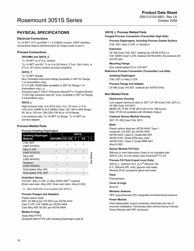
PHYSICAL SPECIFICATIONS
Electrical Connections1/2–14 NPT, G1/2, and M20 × 1.5 (CM20) conduit. HART interface
connections fixed to terminal block for Output code A and X.
Process Connections
3051SMV and 3051S_C1/4–18 NPT on 21/8-in. centers1/2–14 NPT and RC 1/2 on 2-in.(50.8mm), 21/8-in. (54.0 mm), or
21/4-in. (57.2mm) centers (process adapters)
3051S_T1/2–14 NPT female,
Non-Threaded instrument flange (available in SST for Range
1–4 transmitters only),
G1/2 A DIN 16288 Male (available in SST for Range 1–4
transmitters only), or
Autoclave type F-250-C (Pressure relieved 9/16–18 gland thread; 1/4 OD high pressure tube 60° cone; available in SST for Range
5 transmitters only).
3051S_L
High pressure side: 2-in.(50.8 mm), 3-in. (72 mm), or 4-in.
(102 mm), ASME B 16.5 (ANSI) Class 150, 300 or 600 flange;
50, 80 or 100 mm, DIN 2501 PN 40 or 10/16 flange
Low pressure side: 1/4–18 NPT on flange, 1/2–14 NPT on
process adapter
Process-Wetted Parts
Process Isolating Diaphragms
Drain/Vent Valves
Process Flanges and Adapters
Plated carbon steel
SST: CF-8M (Cast 316 SST) per ASTM A743
Cast C-276: CW-12MW per ASTM A494
Cast Alloy 400: M-30C per ASTM A494
Wetted O-rings
Glass-filled PTFE
(Graphite-filled PTFE with Isolating Diaphragm code 6)
3051S_L Process Wetted Parts
Flanged Process Connection (Transmitter High Side)
Process Diaphragms, Including Process Gasket Surface
316L SST, Alloy C-276, or Tantalum
Extension
CF-3M (Cast 316L SST, material per ASTM A743), or
CW-12MW (Cast C-276, material ASTM A494); fits schedule 40
and 80 pipe
Mounting Flange
Zinc-cobalt plated CS or 316 SST
Reference Process Connection (Transmitter Low Side)
Isolating Diaphragms
316L SST or Alloy C-276
Process Flange and Adapter
CF-8M (Cast 316 SST, material per ASTM A743)
Non-Wetted Parts
Electronics Housing
Low-copper aluminum alloy or SST: CF-3M (Cast 316L SST) or
CF-8M (Cast 316 SST)
NEMA 4X, IP 66, IP 68 (66 ft (20 m) for 168 hours)
Note: IP 68 not available with Wireless Output.
Coplanar Sensor Module Housing
SST: CF-3M (Cast 316L SST)
Bolts
Plated carbon steel per ASTM A449, Type 1
Austenitic 316 SST per ASTM F593
ASTM A453, Class D, Grade 660 SST
ASTM A193, Grade B7M alloy steel
ASTM A193, Class 2, Grade B8M SST
Alloy K-500
Sensor Module Fill Fluid
Silicone or inert halocarbon (Inert is not available with
3051S_CA). In-Line series uses Fluorinert® FC-43.
Process Fill Fluid (Liquid Level Only)
3051S_L: Syltherm XLT, D.C.® Silicone 704,
D.C. Silicone 200, inert, glycerin and water,
Neobee M-20, propylene glycol and water.
Paint
Polyurethane
Cover O-rings
Buna-N
Wireless Antenna
PBT/ polycarbonate (PC) integrated omnidirectional antenna
Power Module
Field replaceable, keyed connection eliminates the risk of
incorrect installation, Intrinsically Safe Lithium-thionyl chloride
Power Module with PBT enclosure
Isolating Diaphragm
Material
3051S_
3051SMV CD, CG T CA L
316L SST
(UNS S31603)• • • •
Se
e B
elo
w
Alloy C-276
(UNS N10276)• • • •
Alloy 400
(UNS N04400)• • •
Tantalum
(UNS R05440)• •
Gold-plated Alloy 400 • • •
Gold-plated 316L SST • • •
316 SST, Alloy C-276, or Alloy 400/K-500(1) material
(Drain vent seat: Alloy 400, Drain vent stem: Alloy K-500)
(1) Alloy 400/K-500 is not available with 3051S_L.
18
Product Data Sheet00813-0100-4801, Rev LA
October 2008 Rosemount 3051S Series
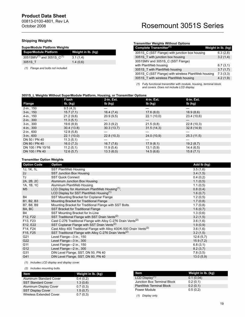
Shipping Weights
SuperModule Platform Weights
Transmitter Weights Without Options
3051S_L Weights Without SuperModule Platform, Housing, or Transmitter Options
Transmitter Option Weights
SuperModule Platform Weight in lb. (kg)
3051SMV(1) and 3051S_C(1)
(1) Flange and bolts not included.
3.1 (1,4)
3051S_T 1.4 (0,6)
Complete Transmitter(1)___________________Weight in lb. (kg)
(1) Fully functional transmitter with module, housing, terminal block,and covers. Does not include LCD display.
3051S_C (SST Flange) with junction box housing 6.3 (2,8)
3051S_T with junction box housing 3.2 (1,4)
3051SMV and 3051S_C (SST Flange)
with PlantWeb housing 6.7 (3,1)
3051S_T with PlantWeb housing 3.7 (1,7)
3051S_C (SST Flange) with wireless PlantWeb housing 7.3 (3,3)
3051S_T with wireless PlantWeb housing 4.2 (1,9)
Flange
Flush
lb. (kg)
2-in. Ext.
lb (kg)
4-in. Ext.
lb (kg)
6-in. Ext.
lb (kg)
2-in., 150 9.5 (4,3) — — —
3-in., 150 15.7 (7,1) 16.4 (7,4) 17.6 (8,0) 18.9 (8,6)
4-in., 150 21.2 (9,6) 20.9 (9,5) 22.1 (10,0) 23.4 (10,6)
2-in., 300 11.3 (5,1) — — —
3-in., 300 19.6 (8,9) 20.3 (9,2) 21.5 (9,8) 22.8 (10,3)
4-in., 300 30.4 (13.8) 30.3 (13,7) 31.5 (14,3) 32.8 (14,9)
2-in., 600 12.8 (5,8) — — —
3-in., 600 22.1 (10,0) 22.8 (10,3) 24.0 (10,9) 25.3 (11,5)
DN 50 / PN 40 11.3 (5,1) — — —
DN 80 / PN 40 16.0 (7,3) 16.7 (7,6) 17.9 (8,1) 19.2 (8,7)
DN 100 / PN 10/16 11.2 (5,1) 11.9 (5,4) 13.1 (5,9) 14.4 (6,5)
DN 100 / PN 40 12.6 (5,7) 13.3 (6,0) 14.5 (6,6) 15.8 (7,1)
Option Code Option Add lb (kg)
1J, 1K, 1L SST PlantWeb Housing 3.5 (1,6)
2J SST Junction Box Housing 3.4 (1,5)
7J SST Quick Connect 0.4 (0,2)
2A, 2B, 2C Aluminum Junction Box Housing 1.1 (0,5)
1A, 1B, 1C Aluminum PlantWeb Housing 1.1 (0,5)
M5 LCD Display for Aluminum PlantWeb Housing(1),
LCD Display for SST PlantWeb Housing(1)0.8 (0,4)
1.6 (0,7)
B4 SST Mounting Bracket for Coplanar Flange 1.2 (0,5)
B1, B2, B3 Mounting Bracket for Traditional Flange 1.7 (0,8)
B7, B8, B9 Mounting Bracket for Traditional Flange with SST Bolts 1.7 (0,8)
BA, BC SST Bracket for Traditional Flange 1.6 (0,7)
B4 SST Mounting Bracket for In-Line 1.3 (0,6)
F12, F22 SST Traditional Flange with SST Drain Vents(2) 3.2 (1,5)
F13, F23 Cast C-276 Traditional Flange with Alloy C-276 Drain Vents(2) 3.6 (1,6)
E12, E22 SST Coplanar Flange with SST Drain Vents(2) 1.9 (0,9)
F14, F24 Cast Alloy 400 Traditional Flange with Alloy 400/K-500 Drain Vents(2) 3.6 (1,6)
F15, F25 SST Traditional Flange with Alloy C-276 Drain Vents(2) 3.2 (1,5)
G21 Level Flange—3 in., 150 12.6 (5,7)
G22 Level Flange—3 in., 300 15.9 (7,2)
G11 Level Flange—2 in., 150 6.8 (3,1)
G12 Level Flange—2 in., 300 8.2 (3,7)
G31 DIN Level Flange, SST, DN 50, PN 40 7.8 (3,5)
G41 DIN Level Flange, SST, DN 80, PN 40 13.0 (5,9)
(1) Includes LCD display and display cover.
(2) Includes mounting bolts.
Item Weight in lb. (kg)
Aluminum Standard Cover 0.4 (0,2)
SST Standard Cover 1.3 (0,6)
Aluminum Display Cover 0.7 (0,3)
SST Display Cover 1.5 (0,7)
Wireless Extended Cover 0.7 (0,3)
LCD Display(1) 0.1 (0,04)
Junction Box Terminal Block 0.2 (0,1)
PlantWeb Terminal Block 0.2 (0,1)
Power Module 0.5 (0,2)
(1) Display only.
Item Weight in lb. (kg)
19

Product Data Sheet00813-0100-4801, Rev LA
October 2008Rosemount 3051S Series
Rosemount 3051S MultiVariable Certifications
Approved Manufacturing LocationsRosemount Inc. — Chanhassen, Minnesota USA
Emerson Process Management GmbH & Co. — Wessling,
Germany
Emerson Process Management Asia Pacific Private Limited —
Singapore
Beijing Rosemount Far East Instrument Co., LTD — Beijing, China
Ordinary Location Certification for FMAs standard, the transmitter has been examined and tested to
determine that the design meets basic electrical, mechanical, and
fire protection requirements by FM, a nationally recognized testing
laboratory (NRTL) as accredited by the Federal Occupational
Safety and Health Administration (OSHA).
European Directive Information
The EC declaration of conformity for all applicable European
directives for this product can be found at www.rosemount.com. A
hard copy may be obtained by contacting an Emerson Process
Management representative.
ATEX Directive (94/9/EC)
Emerson Process Management complies with the
ATEX Directive.
European Pressure Equipment Directive (PED) (97/23/EC)
Models with Differential Pressure Ranges = 2 to 5 inclusive with
Static Pressure = Range 4 only. P9 and P0 options also.
All other Model 3051SMV Pressure Transmitters
— Sound Engineering Practice
Transmitter Attachments: Diaphragm Seal - Process Flange -
Manifold — Sound Engineering Practice
Primary Elements, Flowmeter
— See appropriate Primary Element QIG
Electro Magnetic Compatibility (EMC) (2004/108/EC)
EN 61326-1:2006 and EN 61326-2-3:2006
Hazardous Locations Certifications
North American Certifications
FM Approvals
E5 Explosion-proof for Class I, Division 1, Groups B, C, and D;
dust-ignition proof for Class II and Class III, Division 1,
Groups E, F, and G; hazardous locations; enclosure Type
4X, conduit seal not required.
I5 Intrinsically Safe for use in Class I, Division 1, Groups A, B,
C, and D; Class II, Division 1, Groups E, F, and G; Class III,
Division 1; Class I, Zone 0 AEx ia IIC when connected in
accordance with Rosemount drawing 03151-1206;
Non-incendive for Class I, Division 2, Groups A, B, C, and D
Enclosure Type 4X
For entity parameters see control drawing 03151-1206.
Canadian Standards Association (CSA)
All CSA hazardous approved transmitters are certified per
ANSI/ISA 12.27.01-2003.
E6 Explosion-proof for Class I, Division 1, Groups B, C, and D;
Dust-Ignition-Proof for Class II and Class III, Division 1,
Groups E, F, and G; suitable for Class I, Division 2, Groups
A, B, C, and D, CSA Enclosure Type 4X; conduit seal not
required.
I6 Intrinsically Safe for Class I, Division 1, Groups A, B, C, and
D when connected in accordance with Rosemount drawings
03151-1207;
For entity parameters see control drawing 03151-1207.
European Certifications
I1 ATEX Intrinsic Safety
Certificate No.: 08ATEX0064X II 1G
Ex ia IIC T4 (Ta = -60 °C to 70 °C) -HART
1180
Special conditions for safe use (x)
The apparatus is not capable of withstanding the 500V test
as defined in Clause 6.3.12 of EN 60079-11. This must be
considered during installation.
N1 ATEX Type n
Certificate No.: Baseefa 08ATEX0065X II 3 G
Ex nA nL IIC T4 (Ta = -40 °C TO 70 °C)
Ui = 45 Vdc max
IP66
Special conditions for safe use (x)
The apparatus is not capable of withstanding the 500V
insulation test required by Clause 6.8.1 of EN 60079-15. This
must be taken into account when installing the apparatus.
ND ATEX Dust
Certificate No.: BAS01ATEX1303X II 1 D
T105°C (-20 °C ≤ Tamb ≤ 85 °C)
Vmax = 42.4 volts max
A = 24 mA
IP66
1180
Input Parameters
Loop / Power Groups
Ui = 30 V HART
Ii = 300 mA HART
Pi = 1.0 W HART
Ci = 14.8 nF HART
Li = 0 HART
20

Product Data Sheet00813-0100-4801, Rev LA
October 2008 Rosemount 3051S Series
21
Special conditions for safe use (x)
The user must ensure that the maximum rated voltage and current
(42.4 volts, 22 milliampere, DC) are not exceeded. All connections
to other apparatus or associated apparatus shall have control over
this voltage and current equivalent to a category “ib” circuit
according to EN 60079-11.
1. Cable entries must be used which maintain the ingress
protection of the enclosure to at least IP66.
2. Unused cable entries must be filled with suitable blanking
plugs which maintain the ingress protection of the
enclosure to at least IP66.
3. Cable entries and blanking plugs must be suitable for the
ambient range of the apparatus and capable of
withstanding a 7J impact test.
4. The 3051SMV must be securely screwed in place to
maintain the ingress protection of the enclosure. (The
3051SMV SuperModule must be properly assembled to
the 3051SMV housing to maintain ingress protection.)
E1 ATEX Flameproof
Certificate No.: KEMA 00ATEX2143X II 1/2 G
Ex d IIC T6 (-50 °C ≤ Tamb ≤ 65 °C)
Ex d IIC T5 (-50 °C ≤ Tamb ≤ 80 °C)
Vmax = 42.4V
1180
Special conditions for safe use (x)
1. Appropriate ex d blanking plugs, cable glands, and wiring
needs to be suitable for a temperature of 90 °C.
2. This device contains a thin wall diaphragm. Installation,
maintenance and use shall take into account the
environmental conditions to which the diaphragm will be
subjected. The manufacturer’s instructions for
maintenance shall be followed in detail to assure safety
during its expected lifetime.
3. The 3051SMV does not comply with the requirements of
IEC 60079-1 Clause 5.2, Table 2 for all joints. Contact
Emerson Process Management for information on the
dimensions of flameproof joints.
Japanese Certifications
E4 TIIS Flameproof
Consult factory for availability
I4 TIIS Intrinsically Safe
Consult factory for availability
INMETRO Certifications
E2 INMETRO Flameproof
BR-Ex d IIC T6/T5
I2 INMETRO Intrinsic Safety
BR-Ex ia IIC T4
China (NEPSI) Certifications
E3 China Flameproof
Ex d II B+H2T3~T5
I3 China Intrinsic Safety
Ex ia IIC T3/T4
IECEx Certifications
I7 IECEx Intrinsic Safety
Certificate No.: IECExBAS08.0025X
Ex ia IIC T4 (Ta = -60 °C to 70 °C) -HART
IP66
Special conditions for safe use (x)
The 3051SMV HART 4-20mA is not capable of withstanding
the 500V test as defined in clause 6.3.12 of IEC 60079-11.
This must be taken into account during installation.
N7 IECEx Type n
Certificate No.: IECExBAS08.0026X
Ex nAnL IIC T4 (Ta = -40 °C to 70 °C)
Ui = 45 Vdc MAX
IP66
Special conditions for safe use (x)
The apparatus is not capable of withstanding the 500 V
insulation test required by Clause 6.8.1 of IEC 60079-15.
E7 IECEx Flameproof
Certificate No.: IECExKEM08.0010X
Ex d IIC T6 (-50 °C ≤ Tamb ≤ 65 °C)
Ex d IIC T5 (-50 °C ≤ Tamb ≤ 80 °C)
Vmax = 42.4V
Special conditions for safe use (x)
1. Appropriate ex d blanking plugs, cable glands, and wiring
needs to be suitable for a temperature of 90 °C.
2. This device contains a thin wall diaphragm. Installation,
maintenance and use shall take into account the
environmental conditions to which the diaphragm will be
subjected. The manufacturer’s instructions for
maintenance shall be followed in detail to assure safety
during its expected lifetime.
3. The 3051SMV does not comply with the requirements of
IEC 60079-1 Clause 5.2, Table 2 for all joints. Contact
Emerson Process Management for information on the
dimensions of flameproof joints.
Combinations of Certifications
Stainless steel certification tag is provided when optional approval
is specified. Once a device labeled with multiple approval types is
installed, it should not be reinstalled using any other approval
types. Permanently mark the approval label to distinguish it from
unused approval types.
K1 Combination of E1, I1, N1, and ND
K2 Combination of E2 and I2
K4 Combination of E4 and I4
K5 Combination of E5 and I5
K6 Combination of E6 and I6
K7 Combination of E7, I7, and N7
KA Combination of E1, E6, I1, and I6
KB Combination of E5, E6, I5, and I6
KC Combination of E5, E1, I5 and I1
KD Combination of E5, E6, E1, I5, I6, and I1
Input Parameters
Loop / Power Groups
Ui = 30 V HART
Ii = 300 mA HART
Pi = 1.0 W HART
Ci = 14.8 nF HART
Li = 0 HART
Product Data Sheet00813-0100-4801, Rev LA
October 2008Rosemount 3051S Series
22
Rosemount 3051S CertificationsApproved Manufacturing LocationsRosemount Inc. — Chanhassen, Minnesota USA
Emerson Process Management GmbH & Co. — Wessling,
Germany
Emerson Process Management Asia Pacific Private Limited —
Singapore
Beijing Rosemount Far East Instrument Co., LTD — Beijing, China
Emerson Process Management LTDA — Sorocaba, Brazil
Emerson Process Management (India) Pvt. Ltd. — Daman, India
Ordinary Location Certification for FMAs standard, the transmitter has been examined and tested to
determine that the design meets basic electrical, mechanical, and
fire protection requirements by FM, a nationally recognized testing
laboratory (NRTL) as accredited by the Federal Occupational
Safety and Health Administration (OSHA).
European Directive InformationThe EC declaration of conformity for all applicable European
directives for this product can be found at www.rosemount.com. A
hard copy may be obtained by contacting an Emerson Process
Management representative.
ATEX Directive (94/9/EC)
Emerson Process Management complies with the
ATEX Directive.
European Pressure Equipment Directive (PED) (97/23/EC)
Models 3051S_CA4; 3051S_CD2, 3, 4, 5; (also with P9 option)
Pressure Transmitters — QS Certificate of Assessment -
EC No. PED-H-100, Module H Conformity Assessment
All other Model 3051S Pressure Transmitters
— Sound Engineering Practice
Transmitter Attachments: Diaphragm Seal - Process Flange -
Manifold — Sound Engineering Practice
Primary Elements, Flowmeter
— See appropriate Primary Element QIG
Electro Magnetic Compatibility (EMC) (2004/108/EC)
EN 61326-1:1997 + A1, A2, and A3 – Industrial
Radio and Telecommunications Terminal Equipment
Directive (R&TTE)(1999/5/EC)
Emerson Process Management complies with the R&TTE
Directive.
HART & FOUNDATION Fieldbus Hazardous Locations Certifications
North American Certifications
FM Approvals
E5 Explosion-proof for Class I, Division 1, Groups B, C, and D;
Dust Ignition-proof for Class II and Class III, Division 1,
Groups E, F, and G; hazardous locations; enclosure Type
4X, conduit seal not required when installed according to
Rosemount drawing 03151-1003.
I5/IE Intrinsically Safe for use in Class I, Division 1, Groups A, B,
C, and D; Class II, Division 1, Groups E, F, and G; Class III,
Division 1; Class I, Zone 0 AEx ia IIC when connected in
accordance with Rosemount drawing 03151-1006;
Non-Incendive for Class I, Division 2, Groups A, B, C, and D
Enclosure Type 4X
For entity parameters see control drawing 03151-1006.
Canadian Standards Association (CSA)
All CSA hazardous approved transmitters are certified per
ANSI/ISA 12.27.01-2003.
E6 Explosion-proof for Class I, Division 1, Groups B, C, and D;
Dust Ignition-proof for Class II and Class III, Division 1,
Groups E, F, and G; suitable for Class I, Division 2, Groups
A, B, C, and D, when installed per Rosemount drawing
03151-1013, CSA Enclosure Type 4X; conduit seal not
required.
I6/IF Intrinsically Safe for Class I, Division 1, Groups A, B, C, and
D when connected in accordance with Rosemount drawings
03151-1016;
For entity parameters see control drawing 03151-1016.
European Certifications
I1/IA ATEX Intrinsic Safety
Certificate No.: BAS01ATEX1303X II 1G
Ex ia IIC T4 (Ta = -60 °C to 70 °C) -HART/Remote
Display/Quick Connect/HART Diagnostics
Ex ia IIC T4 (Ta = -60 °C to 70 °C) -FOUNDATION fieldbus
Ex ia IIC T4 (Ta = -60 °C to 40 °C) -FISCO
1180
Special conditions for safe use (x)
1. The apparatus, excluding the Types 3051 S-T and 3051
S-C (In-line and Coplanar SuperModule Platforms
respectively), is not capable of withstanding the 500V test
as defined in Clause 6.4.12 of EN 50020. This must be
considered during installation.
2. The terminal pins of the Types 3051 S-T and 3051 S-C
must be protected to IP20 minimum.
Input Parameters
Loop /
Power Groups
Ui = 30 V HART / FOUNDATION fieldbus/ Remote Display /
Quick Connect / HART Diagnostics
Ui = 17.5 V FISCO
Ii = 300 mA HART / FOUNDATION fieldbus/ Remote Display /
Quick Connect / HART Diagnostics
Ii = 380 mA FISCO
Pi = 1.0 W HART / Remote Display / Quick Connect /
HART Diagnostics
Pi = 1.3 W FOUNDATION fieldbus
Pi = 5.32 W FISCO
Ci = 30 nF SuperModule Platform / Quick Connect
Ci = 11.4 nF HART / HART Diagnostics
Ci = 0 FOUNDATION fieldbus / Remote Display / FISCO
Li = 0 HART / FOUNDATION fieldbus/ FISCO / Quick
Connect / HART Diagnostics
Li = 60 µH Remote Display

Product Data Sheet00813-0100-4801, Rev LA
October 2008 Rosemount 3051S Series
23
N1 ATEX Type n
Certificate No.: BAS01ATEX3304X II 3 G
EEx nAnL IIC T4 (Ta = -40 °C TO 70 °C)
Ui = 45 Vdc max
IP66
Special conditions for safe use (x)
The apparatus is not capable of withstanding the 500V insulation
test required by Clause 6.8.1 of EN 60079-15.
This must be taken into account when installing the apparatus.
ND ATEX Dust
Certificate No.: BAS01ATEX1374X II 1 D
T105°C (-20 °C ≤ Tamb ≤ 85 °C)
Vmax = 42.4 volts max
A = 22 mA
IP66
1180
Special conditions for safe use (x)
1. The user must ensure that the maximum rated voltage and
current (42.4 volts, 22 milliampere, DC) are not exceeded. All
connections to other apparatus or associated apparatus shall
have control over this voltage and current equivalent to a
category “ib” circuit according to EN 50020.
2. Cable entries must be used which maintain the ingress
protection of the enclosure to at least IP66.
3. Unused cable entries must be filled with suitable blanking
plugs which maintain the ingress protection of the enclosure
to at least IP66.
4. Cable entries and blanking plugs must be suitable for the
ambient range of the apparatus and capable of withstanding
a 7J impact test.
5. The 3051S must be securely screwed in place to maintain the
ingress protection of the enclosure. (The 3051S
SuperModule must be properly assembled to the 3051S
housing to maintain ingress protection.)
E1 ATEX Flameproof
Certificate No.: KEMA00ATEX2143X II 1/2 G
Ex d IIC T6 (-50 °C ≤ Tamb ≤ 65 °C)
Ex d IIC T5 (-50 °C ≤ Tamb ≤ 80 °C)
Vmax = 42.4V
1180
Special conditions for safe use (x)
1. Appropriate ex d blanking plugs, cable glands, and wiring
needs to be suitable for a temperature of 90 °C.
2. This device contains a thin wall diaphragm. Installation,
maintenance and use shall take into account the
environmental conditions to which the diaphragm will be
subjected. The manufacturer’s instructions for maintenance
shall be followed in detail to assure safety during its expected
lifetime.
3. The 3051S does not comply with the requirements of EN
60079-1 Clause 5.2, Table 2 for all joints. Contact Emerson
Process Management for information on the dimensions of
flameproof joints.
Japanese Certifications
E4 TIIS Flameproof
Ex d IIC T6
China (NEPSI) Certifications
I3 China Intrinsic Safety
Certificate No. (manufactured in Chanhassen, MN): GYJ081078
Certificate No. (manufactured in Beijing, China): GYJ06367
Ex ia IIC T3~T5
E3 China Flameproof
Certificate No.: GYJ06366
Ex d IIB+H2 T3~T5
INMETRO Certifications
I2 INMETRO Intrinsic Safety
Certificate No. (manufactured in Chanhassen, MN):
CEPEL-Ex-0722/05X
Certificate No. (manufactured in Brazil): CEPEL-Ex-1414/07X
BR-Ex ia IIC T4 IP66W
E2 INMETRO Flameproof
Certificate No. (manufactured in Chanhassen, MN):
CEPEL-Ex-140/2003X
Certificate No. (manufactured in Brazil): CEPEL-Ex-1413/07X
BR-Ex d IIC T5/T6 IP66W
Certificate Description
TC15682 Coplanar with Junction Box Housing
TC15683 Coplanar with PlantWeb Housing
TC15684 Coplanar with PlantWeb Housing
and LCD Display
TC15685 In-Line SST with Junction Box Housing
TC15686 In-Line Alloy C-276 with Junction Box Housing
TC15687 In-Line SST with PlantWeb Housing
TC15688 In-Line Alloy C-276 with PlantWeb Housing
TC15689 In-Line SST with PlantWeb Housing
and LCD Display
TC15690 In-Line Alloy C-276 with PlantWeb Housing
and LCD Display
TC17102 Remote Display
Input Parameters
Loop /
Power Groups
Ui = 30 V HART / FOUNDATION fieldbus/ Remote Display /
Quick Connect / HART Diagnostics
Ui = 17.5 V FISCO
Ii = 300 mA HART / FOUNDATION fieldbus/ Remote Display /
Quick Connect / HART Diagnostics
Ii = 380 mA FISCO
Pi = 1.0 W HART / Remote Display / Quick Connect /
HART Diagnostics
Pi = 1.3 W FOUNDATION fieldbus
Pi = 5.32 W FISCO
Ci = 30 nF SuperModule Platform / Quick Connect
Ci = 11.4 nF HART / HART Diagnostics
Ci = 0 FOUNDATION fieldbus / Remote Display / FISCO
Li = 0 HART / FOUNDATION fieldbus/ FISCO / Quick
Connect / HART Diagnostics
Li = 60 µH Remote Display

Product Data Sheet00813-0100-4801, Rev LA
October 2008Rosemount 3051S Series
IECEx Certifications
E7 IECEx Flameproof
Certificate No.: IECExKEM08.0010X
Ex d IIC T6 (-50 °C ≤ Tamb ≤ 65 °C)
Ex d IIC T5 (-50 °C ≤ Tamb ≤ 80 °C)
Vmax = 42.4V
Special conditions for safe use (x)
1. Appropriate ex d blanking plugs, cable glands, and wiring
needs to be suitable for a temperature of 90 °C.
2. This device contains a thin wall diaphragm. Installation,
maintenance and use shall take into account the
environmental conditions to which the diaphragm will be
subjected. The manufacturer’s instructions for
maintenance shall be followed in detail to assure safety
during its expected lifetime.
3. The 3051S does not comply with the requirements of IEC
60079-1 Clause 5.2, Table 2 for all joints. Contact
Emerson Process Management for information on the
dimensions of flameproof joints.
I7/IG IECEx Intrinsic Safety
Certificate No.: IECExBAS04.0017X
Ex ia IIC T4 (Ta = -60 °C to 70 °C) -HART/Remote
Display/Quick Connect/HART Diagnostics
Ex ia IIC T4 (Ta = -60 °C to 70 °C) -FOUNDATION fieldbus
Ex ia IIC T4 (Ta = -60 °C to 40 °C) -FISCO
IP66
Special conditions for safe use (x)
1. The Models 3051S HART 4-20mA, 3051S fieldbus, 3051S
Profibus and 3051S FISCO are not capable of
withstanding the 500V test as defined in clause 6.4.12 of
IEC 60079-11. This must be taken into account during
installation.
2. The terminal pins of the Types 3051S-T and 3051S-C must
be protected to IP20 minimum.
N7 IECEx Type n
Certificate No.: IECExBAS04.0018X
Ex nC IIC T4 (Ta = -40 °C to 70 °C)
Ui = 45 Vdc MAX
IP66
Special conditions for safe use (x)
The apparatus is not capable of withstanding the 500 V
insulation test required by Clause 8 of IEC 60079-15.
Combinations of Certifications
Stainless steel certification tag is provided when optional approval
is specified. Once a device labeled with multiple approval types is
installed, it should not be reinstalled using any other approval
types. Permanently mark the approval label to distinguish it from
unused approval types.
K1 Combination of E1, I1, N1, and ND
K2 Combination of E2 and I2
K5 Combination of E5 and I5
K6 Combination of E6 and I6
K7 Combination of E7, I7, and N7
KA Combination of E1, I1, E6, and I6
KB Combination of E5, I5, I6 and E6
KC Combination of E5, E1, I5 and I1
KD Combination of E5, I5, E6, I6, E1, and I1
Input Parameters
Loop / Power Groups
Ui = 30 V HART / FOUNDATION fieldbus/
Remote Display / Quick Connect
/ HART Diagnostics
Ui = 17.5 V FISCO
Ii = 300 mA HART / FOUNDATION fieldbus/
Remote Display / Quick Connect
/ HART Diagnostics
Ii = 380 mA FISCO
Pi = 1.0 W HART / Remote Display / Quick
Connect / HART Diagnostics
Pi = 1.3 W FOUNDATION fieldbus
Pi = 5.32 W FISCO
Ci = 30 nF SuperModule Platform / Quick
Connect
Ci = 11.4 nF HART / HART Diagnostics
Ci = 0 FOUNDATION fieldbus / Remote
Display / FISCO / Quick Connect
/ HART Diagnostics
Li = 0 HART / FOUNDATION fieldbus /
FISCO / Quick Connect / HART
Diagnostics
Li = 60 H Remote Displayµ
24

Product Data Sheet00813-0100-4801, Rev LA
October 2008 Rosemount 3051S Series
25
Rosemount 3051S Wireless Certifications
Approved Manufacturing LocationsRosemount Inc. — Chanhassen, Minnesota USA
Emerson Process Management GmbH & Co. — Wessling,
Germany
Emerson Process Management Asia Pacific Private Limited —
Singapore
Beijing Rosemount Far East Instrument Co., LTD — Beijing, China
Emerson Process Management LTDA — Sorocaba, Brazil
Emerson Process Management (India) Pvt. Ltd. — Daman, India
Telecommunication Compliance
All wireless devices require certification to ensure that they adhere
to regulations regarding the use of the RF spectrum. Nearly every
country requires this type of product certification. Emerson is
working with governmental agencies around the world to supply
fully compliant products and remove the risk of violating country
directives or laws governing wireless device usage.
FCC and IC ApprovalsThis device complies with Part 15 of the FCC Rules. Operation is
subject to the following conditions: This device may not cause
harmful interference this device and must accept any interference
received, including interference that may cause undesired
operation.
This device must be installed to ensure a minimum antenna
separation distance of 20cm from all persons.
Ordinary Location Certification for FMAs standard, the transmitter has been examined and tested to
determine that the design meets basic electrical, mechanical, and
fire protection requirements by FM, a nationally recognized testing
laboratory (NRTL) as accredited by the Federal Occupational
Safety and Health Administration (OSHA).
European Directive InformationThe EC declaration of conformity for all applicable European
directives for this product can be found at www.rosemount.com. A
hard copy may be obtained by contacting an Emerson Process
Management representative.
ATEX Directive (94/9/EC)
Emerson Process Management complies with the ATEX
Directive.
European Pressure Equipment Directive (PED) (97/23/EC)
Models 3051S_CA4; 3051S_CD2, 3, 4, 5; (also with P9 option)
Pressure Transmitters — QS Certificate of Assessment -
EC No. PED-H-100, Module H Conformity Assessment
All other Model 3051S Pressure Transmitters
— Sound Engineering Practice
Transmitter Attachments: Diaphragm Seal - Process Flange -
Manifold — Sound Engineering Practice
Primary Elements, Flowmeter
— See appropriate Primary Element QIG
Radio and Telecommunications Terminal Equipment Directive
(R&TTE)(1999/5/EC)
Emerson Process Management complies with the R&TTE
Directive.
Hazardous Locations Certifications
North American CertificationsFactory Mutual (FM) Approvals
I5 FM Intrinsically Safe, Non-Incendive, and Dust
Ignition-proof.
Intrinsically Safe for Class I/II/III, Division 1,
Groups A, B, C, D, E, F, and G.
Zone Marking: Class I, Zone 0, AEx ia llC
Temperature Codes T4 (Tamb = -50 to 70° C)
Non-Incendive for Class I, Division 2, Groups A, B, C, and
D.
Dust Ignition-proof for Class II/III, Division 1,
Groups E, F, and G.
Ambient temperature limits: -50 to 85° C
For use with Rosemount SmartPower options
00753-9220-0001 only.
Enclosure Type 4X / IP66
CSA - Canadian Standards Association
Process Sealing
All CSA hazardous approved transmitters are certified per
ANSI/ISA 12.27.01-2003.
I6 CSA Intrinsically Safe
Intrinsically Safe for Class I, Division 1, Groups A, B, C, and
D.
Temp Code T3C
Enclosure Type 4X / IP66
For use with Rosemount SmartPower options
00753-9220-0001 only.
Electro Magnetic Compatibility (EMC) (2004/108/EC)
EN 61326-1:1997 A1, A2, A3(1)
EN 61326-1:2006
EN 61326-2-3:2006
(1) Only applies to “Operating Frequency and Protocol” option code 1.

Product Data Sheet00813-0100-4801, Rev LA
October 2008Rosemount 3051S Series
26
European Certifications
I1 ATEX Intrinsic Safety
Certificate No.: BAS01ATEX1303X II 1G
Ex ia IIC T4 (Ta = -60 °C to 70 °C)
IP66
For use with Rosemount SmartPower options
00753-9220-0001 only.
1180
IECEx Certifications
I7 IECEx Intrinsic Safety
Certificate No.: IECEx BAS 04.0017X
Ex ia IIC T4 (Ta = -60 °C to 70 °C)
For use with Rosemount SmartPower options
00753-9220-0001 only.
IP66
Country(1)
(1) Only applies to “Operating Frequency and Protocol” option code 1.
Restriction
Bulgaria General authorization required for outdoor use and public service
France Outdoor use limited to 10mW e.i.r.p.
Italy If used outside of own premises, general authorization is required.
Norway May be restricted in the geographical area within a radius of 20 km from the center of Ny-Alesund.
Romania Use on a secondary basis. Individual license required.
Radio Power Label (See
Figure 1) indicates output
power configuration of the radio.
Devices with this label are
configured for output power less
than 10 mW e.i.r.p. At time of
purchase the customer must
specify ultimate country of
installation and operation.
(1)
Radio Power Label
Figure 1.

Product Data Sheet00813-0100-4801, Rev LA
October 2008 Rosemount 3051S Series
27
Dimensional Drawings
Dimensions are in inches (millimeters).
Process adapters (option D2) and Rosemount 305 integral manifolds must be ordered with the transmitter.
PlantWeb Housing with Coplanar SuperModule Platformand 305 Coplanar Integral Manifold
PlantWeb Housing with Coplanar SuperModule Platform and Coplanar Flange
4.20 (107)
7.70
(196)
9.03
(230)
5.00 Max open
(127 Max open)
1/2-14 NPT
5.21 (132)
4.55 (116)
4.60 Max open
(117 Max open)
4.60 Max open
(117 Max open)
4.20 (107)
8.53
(217)
9.63
(245)
4.55 (116)
6.44 (164)

Product Data Sheet00813-0100-4801, Rev LA
October 2008Rosemount 3051S Series
28
Dimensions are in inches (millimeters).
Wireless PlantWeb Housing with In-Line and Coplanar SuperModule Platform
90°
10.91
(277)
4.20
(107)
900 MHz
Antenna
7.70
(196)
6.93
(176)
2.4 GHz
Antenna
Coplanar Flange
Process Connection
per IEC 81518Flange Adapters
(Optional)
Drain/
Vent
Nameplate
8.53
(217) 9.63
(245)
6.72
(171)
6.06
(155)
3.46
(87.8)
3.46
(87.8)
6.93
(176)
Conduit
EntryU-Bolt Bracket
1/2-14 NPT Female or
G1/2 A DIN 16288 Male
Process Connection
7.97
(202)
6.44
(154)

Product Data Sheet00813-0100-4801, Rev LA
October 2008 Rosemount 3051S Series
29
Dimensions are in inches (millimeters).
Wireless PlantWeb Housing with 3051S_L Liquid Level
6.93
(176)
90°
10.91
(277)
4.20
(107)
900 MHz Antenna
2.4 GHzAntenna
3.46
(87.8)
6.72
(171)6.06
(155)
7.09
(180)8.55
(217)
9.65
(245)
Flange Adapters
(Optional)
Drain/Vent
Nameplate

Product Data Sheet00813-0100-4801, Rev LA
October 2008Rosemount 3051S Series
30
.
Dimensions are in inches (millimeters).
Junction Box Housing with Coplanar SuperModule Platform and Coplanar Flange
3.45 (88)
6.44 (164)
4.20 (107)
8.53
(217)
9.63
(245)
Quick Connect with Coplanar SuperModule Platform and Coplanar Flange
6.78
(172)
1.10 (28)
1.50
(38)
2.57 (65)
2.90 (74)

Product Data Sheet00813-0100-4801, Rev LA
October 2008 Rosemount 3051S Series
Dimensions are in inches (millimeters).
Coplanar Flange Mounting Configurations
Pipe Mount Panel Mount
6.25 (159)3.54 (90)
2.58 (66) 4.55 (116)
6.15
(156)2.81
(71)
4.70 (120)
31
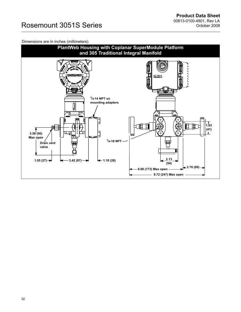
Product Data Sheet00813-0100-4801, Rev LA
October 2008Rosemount 3051S Series
32
Dimensions are in inches (millimeters).
PlantWeb Housing with Coplanar SuperModule Platformand 305 Traditional Integral Manifold
1.63
(41)
2.13
(54)
2.70 (69)6.80 (173) Max open
9.72 (247) Max open
1/4-18 NPT
1.05 (27) 3.42 (87)
Drain vent
valve
1.10 (28)
3.56 (90)
Max open
1/2-14 NPT on
mounting adapters

Product Data Sheet00813-0100-4801, Rev LA
October 2008 Rosemount 3051S Series
Dimensions are in inches (millimeters).
PlantWeb Housing with Coplanar SuperModule Platform and Traditional Flange
9.26
(235)
3.40 (86)1.10
(28)2.13
1.63 (41)
(54)
33

Product Data Sheet00813-0100-4801, Rev LA
October 2008Rosemount 3051S Series
Dimensions are in inches (millimeters).
Traditional Flange Mounting Configurations
Pipe Mount 305 Integral Manifold Panel Mount
8.18 (208)
1.10 (28)
3.56 Max open(90 Max open)
3.42 (87)
2.62 (67)
0.93 (24)
13.03 (331)
4.85 (123)
1.10
(28)
3.42
(87)
3.56 Max open(90 Max open)
1.94 (49)
5.32 (135)7.70 (196)
7.70 (196)
10.70 (272)
2.62
(67)
34

Product Data Sheet00813-0100-4801, Rev LA
October 2008 Rosemount 3051S Series
Dimensions are in inches (millimeters).
Remote Mount LCD Display and Interface Mounting Configurations
Pipe Mount Panel Mount
1.82 (46)
3.08 (78)
6.90 (175)
6.24 (158)
2.66
(68)
2.33
(59)5.19 (132)
4.72 (120)
2.66
(68)
6.15
(156)
4.48
(114
PlantWeb Housing, Junction Box Housing, and Quick Connect with In-Line SuperModule Platform
3.45 (88)4.20 (107)
7.97
(202)
4.55 (116)
1.37
(35)
6.22
(158)
I-Flange
Process
Connector
2.40
(61)
7.97
(202)
2.57
(65)
1.50
(38)
35

Product Data Sheet00813-0100-4801, Rev LA
October 2008Rosemount 3051S Series
36
Dimensions are in inches (millimeters).
In-line Mounting Configurations with Optional Mounting Bracket
Pipe Mount Panel Mount
6.25 (159)
3.08 (78)
6.15
(156) 2.81
(71)
4.72 (120)
6.90 (175)
4.55 (116)2.58
(66)
6.15
(156)

Product Data Sheet00813-0100-4801, Rev LA
October 2008 Rosemount 3051S Series
Dimensions are in inches (millimeters).
3051S_L Liquid Level
Flush Flanged Configuration Extended Flanged Configuration
Optional Flushing Connection Ring
(Lower Housing)
Diaphragm Assembly and
Mounting Flange
Gasket
A
4.20 (107)
H
A
Extension
2, 4, or 6 (51, 102, or 152)
E D
4.20 (107)
H
5.21 (132)
7.09
(180)
4.55 (116)
9.65
(245)8.53
(217)
Flushing Connection
E
F
G
CB
37

Product Data Sheet00813-0100-4801, Rev LA
October 2008Rosemount 3051S Series
(1) Tolerances are 0.040 (1,02), –0.020 (0,51).
3051S_L Dimensional Specifications
Except where indicated, dimensions are in inches (millimeters).
Class
Pipe
Size
Flange
Thickness A
Bolt Circle
Diameter B
Outside
Diameter C
No. of
Bolts
Bolt Hole
Diameter
Extension
Diameter(1) D
O.D. Gasket
Surface E
ASME B16.5 (ANSI) 150 2 (51) 0.69 (18) 4.75 (121) 6.0 (152) 4 0.75 (19) N/A 3.6 (92)
3 (76) 0.88 (22) 6.0 (152) 7.5 (191) 4 0.75 (19) 2.58 (66) 5.0 (127)
4 (102) 0.88 (22) 7.5 (191) 9.0 (229) 8 0.75 (19) 3.5 (89) 6.2 (158)
ASME B16.5 (ANSI) 300 2 (51) 0.82 (21) 5.0 (127) 6.5 (165) 8 0.75 (19) N/A 3.6 (92)
3 (76) 1.06 (27) 6.62 (168) 8.25 (210) 8 0.88 (22) 2.58 (66) 5.0 (127)
4 (102) 1.19 (30) 7.88 (200) 10.0 (254) 8 0.88 (22) 3.5 (89) 6.2 (158)
ASME B16.5 (ANSI) 600 2 (51) 1.00 (25) 5.0 (127) 6.5 (165) 8 0.75 (19) N/A 3.6 (92)
3 (76) 1.25 (32) 6.62 (168) 8.25 (210) 8 0.88 (22) 2.58 (66) 5.0 (127)
DIN 2501 PN 10–40 DN 50 20 mm 125 mm 165 mm 4 18 mm N/A 4.0 (102)
DIN 2501 PN 25/40 DN 80 24 mm 160 mm 200 mm 8 18 mm 65 mm 5.4 (138)
DN 100 24 mm 190 mm 235 mm 8 22 mm 89 mm 6.2 (158)
DIN 2501 PN 10/16 DN 100 20 mm 180 mm 220 mm 8 18 mm 89 mm 6.2 (158)
Class
Pipe
Size
Process
Side F
Lower Housing G
H1/4 NPT 1/2 NPT
ASME B16.5 (ANSI) 150 2 (51) 2.12 (54) 0.97 (25) 1.31 (33) 5.65 (143)
3 (76) 3.6 (91) 0.97 (25) 1.31 (33) 5.65 (143)
4 (102) 3.6 (91) 0.97 (25) 1.31 (33) 5.65 (143)
ASME B16.5 (ANSI) 300 2 (51) 2.12 (54) 0.97 (25) 1.31 (33) 5.65 (143)
3 (76) 3.6 (91) 0.97 (25) 1.31 (33) 5.65 (143)
4 (102) 3.6 (91) 0.97 (25) 1.31 (33) 5.65 (143)
ASME B16.5 (ANSI) 600 2 (51) 2.12 (54) 0.97 (25) 1.31 (33) 7.65 (194)
3 (76) 3.6 (91) 0.97 (25) 1.31 (33) 7.65 (194)
DIN 2501 PN 10–40 DN 50 2.4 (61) 0.97 (25) 1.31 (33) 5.65 (143)
DIN 2501 PN 25/40 DN 80 3.6 (91) 0.97 (25) 1.31 (33) 5.65 (143)
DN 100 3.6 (91) 0.97 (25) 1.31 (33) 5.65 (143)
DIN 2501 PN 10/16 DN 100 3.6 (91) 0.97 (25) 1.31 (33) 5.65 (143)
38

Product Data Sheet00813-0100-4801, Rev LA
October 2008 Rosemount 3051S Series
Ordering Information
Rosemount 3051S MultiVariable Transmitter
Model Transmitter Type
3051SMV MultiVariable Transmitter
Code Performance Class
3051SMV MultiVariable SuperModule, Measurement Types 1 and 2
3 Ultra for Flow: 0.04 % reading DP accuracy, 200:1 rangedown,10-year stability, 12-year limited warranty
5 Classic MV: 0.04% span DP accuracy, 100:1 rangedown, 5-year stability
3051SMV Single Variable SuperModule, Measurement Types 3 and 4
1 Ultra: 0.025 % span DP accuracy, 200:1 rangedown, 10-year stability, 12-year limited warranty
2 Classic: 0.055 % span DP accuracy, 100:1 rangedown, 5-year stability
3 Ultra for Flow: 0.04 % reading DP accuracy, 200:1 rangedown,10-year stability, 12-year limited warranty
Code MultiVariable Type
M MultiVariable Measurement with Fully Compensated Mass and Energy Flow
P MultiVariable Measurement with Direct Process Variable Output
Code Measurement Type
1 Differential Pressure, Static Pressure, and Temperature
2 Differential Pressure and Static Pressure
3 Differential Pressure and Temperature
4 Differential Pressure
Code Differential Pressure Range
0(1)(2) -3 to 3 inH2O (-7,47 to 7,47 mbar)
1 -25 to 25 inH2O (-62,2 to 62,2 mbar)
2 -250 to 250 inH2O (-623 to 623 mbar)
3 -1000 to 1000 inH2O (-2,5 to 2,5 bar)
4(1) -300 to 300 psi (-20,7 to 20,7 bar)
5(1) -2000 to 2000 psi (-137,9 to 137,9 bar)
Code Static Pressure Type
N(3) None
A Absolute
G Gage
Code Static Pressure Range Absolute Gage
N(3) None
3 Range 3 0.5 to 800 psia (0,03 to 55,2 bar) -14.2 to 800 psig (-0,98 to 55,2 bar)
4(4) Range 4 0.5 to 3626 psia (0,03 to 250 bar) -14.2 to 3626 psig (-0,98 to 250 bar)
Code Temperature Input
N(5) None
R(6) RTD Input (Type Pt 100, -328 to 1562 °F (-200 to 850 °C))
Code Isolating Diaphragm
2(7) 316L SST
3(7) Alloy C-276
4 Alloy 400
5(8) Tantalum
6 Gold-Plated Alloy 400 (includes Graphite-Filled PTFE O-ring)
7 Gold-Plated 316L SST
Code Process Connection Size Material Type(9)
Flange Material Drain Vent Bolting
000 None
A11(10) Assemble to Rosemount 305/306 Integral Manifold
A12(10) Assemble to Rosemount 304 or AMF Manifold with SST Traditional Flange
B11(10)(11) Assemble to one Rosemount 1199 Diaphragm Seal
B12(10)(11) Assemble to two Rosemount 1199 Diaphragm Seals
C11(10) Assemble to Rosemount 405 Primary Element
D11(10) Assemble to Rosemount 1195 Integral Orifice and Rosemount 305 Integral Manifold
39
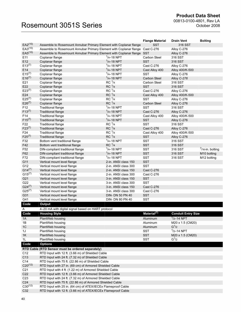
Product Data Sheet00813-0100-4801, Rev LA
October 2008Rosemount 3051S Series
Flange Material Drain Vent Bolting
EA2(10) Assemble to Rosemount Annubar Primary Element with Coplanar flange SST 316 SST
EA3(10) Assemble to Rosemount Annubar Primary Element with Coplanar flange Cast C-276 Alloy C-276
EA5(10) Assemble to Rosemount Annubar Primary Element with Coplanar flange SST Alloy C-276
E11 Coplanar flange 1/4–18 NPT Carbon Steel 316 SST
E12 Coplanar flange 1/4–18 NPT SST 316 SST
E13(7) Coplanar flange 1/4–18 NPT Cast C-276 Alloy C-276
E14 Coplanar flange 1/4–18 NPT Cast Alloy 400 Alloy 400/K-500
E15(7) Coplanar flange 1/4–18 NPT SST Alloy C-276
E16(7) Coplanar flange 1/4–18 NPT Carbon Steel Alloy C-276
E21 Coplanar flange RC 1/4 Carbon Steel 316 SST
E22 Coplanar flange RC 1/4 SST 316 SST
E23(7) Coplanar flange RC 1/4 Cast C-276 Alloy C-276
E24 Coplanar flange RC 1/4 Cast Alloy 400 Alloy 400/K-500
E25(7) Coplanar flange RC 1/4 SST Alloy C-276
E26(7) Coplanar flange RC 1/4 Carbon Steel Alloy C-276
F12 Traditional flange 1/4–18 NPT SST 316 SST
F13(7) Traditional flange 1/4–18 NPT Cast C-276 Alloy C-276
F14 Traditional flange 1/4–18 NPT Cast Alloy 400 Alloy 400/K-500
F15(7) Traditional flange 1/4–18 NPT SST Alloy C-276
F22 Traditional flange RC 1/4 SST 316 SST
F23(7) Traditional flange RC 1/4 Cast C-276 Alloy C-276
F24 Traditional flange RC 1/4 Cast Alloy 400 Alloy 400/K-500
F25(7) Traditional flange RC 1/4 SST Alloy C-276
F32 Bottom vent traditional flange 1/4–18 NPT SST 316 SST
F42 Bottom vent traditional flange RC 1/4 SST 316 SST
F52 DIN-compliant traditional flange 1/4–18 NPT SST 316 SST 7/16-in. bolting
F62 DIN-compliant traditional flange 1/4–18 NPT SST 316 SST M10 bolting
F72 DIN-compliant traditional flange 1/4–18 NPT SST 316 SST M12 bolting
G11 Vertical mount level flange 2-in. ANSI class 150 SST
G12 Vertical mount level flange 2-in. ANSI class 300 SST
G14(7) Vertical mount level flange 2-in. ANSI class 150 Cast C-276
G15(7) Vertical mount level flange 2-in. ANSI class 300 Cast C-276
G21 Vertical mount level flange 3-in. ANSI class 150 SST
G22 Vertical mount level flange 3-in. ANSI class 300 SST
G24(7) Vertical mount level flange 3-in. ANSI class 150 Cast C-276
G25(7) Vertical mount level flange 3-in. ANSI class 300 Cast C-276
G31 Vertical mount level flange DIN- DN 50 PN 40 SST
G41 Vertical mount level flange DIN- DN 80 PN 40 SST
Code Output
A 4–20 mA with digital signal based on HART protocol
Code Housing Style Material(7) Conduit Entry Size
1A PlantWeb housing Aluminum 1/2–14 NPT
1B PlantWeb housing Aluminum M20 x 1.5 (CM20)
1C PlantWeb housing Aluminum G1/2
1J PlantWeb housing SST 1/2–14 NPT
1K PlantWeb housing SST M20 x 1.5 (CM20)
1L PlantWeb housing SST G1/2
Code Options
RTD Cable (RTD Sensor must be ordered separately)
C12 RTD Input with 12 ft. (3.66 m) of Shielded Cable
C13 RTD Input with 24 ft. (7.32 m) of Shielded Cable
C14 RTD Input with 75 ft. (22.86 m) of Shielded Cable
C20(12) RTD Input with 27 in. (69 cm) of Armored Shielded Cable
C21 RTD Input with 4 ft. (1.22 m) of Armored Shielded Cable
C22 RTD Input with 12 ft. (3.66 m) of Armored Shielded Cable
C23 RTD Input with 24 ft. (7.32 m) of Armored Shielded Cable
C24 RTD Input with 75 ft. (22.86 m) of Armored Shielded Cable
C30(12) RTD Input with 25 in. (64 cm) of ATEX/IECEx Flameproof Cable
C32 RTD Input with 12 ft. (3.66 m) of ATEX/IECEx Flameproof Cable
40

Product Data Sheet00813-0100-4801, Rev LA
October 2008 Rosemount 3051S Series
C33 RTD Input with 24 ft. (7.32 m) of ATEX/IECEx Flameproof Cable
C34 RTD Input with 75 ft. (22.86 m) of ATEX/IECEx Flameproof Cable
C40(12) RTD Input with 34 in. (86.36 cm) Shielded Cable and 24 in. (60.96 cm) FM Approved Coupling Flex
C41(12) RTD Input with 40 in. (101.60 cm) Shielded Cable and 30 in. (76.20 cm) FM Approved Coupling Flex
Mounting Brackets(13)
B4 Coplanar flange bracket, all SST, 2-in. pipe and panel
B1 Traditional flange bracket, Carbon Steel, 2-in. pipe
B2 Traditional flange bracket, Carbon Steel, panel
B3 Traditional flange flat bracket, Carbon Steel, 2-in. pipe
B7 Traditional flange bracket, B1 with SST bolts
B8 Traditional flange bracket, B2 with SST bolts
B9 Traditional flange bracket, B3 with SST bolts
BA Traditional flange bracket, B1, all SST
BC Traditional flange bracket, B3, all SST
Special Configuration (Software)
C1 Custom software configuration
Note: A Configuration Data Sheet must be completed, see document number 00806-0100-4803.
C2 Custom flow configuration
Note: A Custom Fluid Data Sheet must be completed, see document number 00806-0200-4803.
C4 NAMUR alarm and saturation levels, high alarm
C5 NAMUR alarm and saturation levels, low alarm
C6 Custom alarm and saturation signal levels, high alarm
C7 Custom alarm and saturation signal levels, low alarm
C8 Low alarm (standard Rosemount alarm and saturation levels)
Special Configuration (Hardware)
D2(13) 1/2-14 NPT Process adapters
D9(13) RC 1/2 process adapters
D4 External ground screw assembly
D5(13) Delete transmitter drain/vent valves (install plugs)
D7(13) Coplanar flange without drain/vent ports
D8(13) Ceramic drain/vent valves
Product Certifications
E1 ATEX Flameproof
I1 ATEX Intrinsic Safety
N1 ATEX Type n
ND ATEX Dust
K1 ATEX Flameproof, Intrinsic Safety, Type n, Dust (combination of E1, I1, N1, and ND)
E4 TIIS Flameproof
I4 TIIS Intrinsic Safety
K4 TIIS Flameproof and Intrinsic Safety (combination E4 and I4)
E5 FM Explosion-proof, Dust Ignition-proof
I5 FM Intrinsically Safe, Division 2
K5 FM Explosion-proof, Dust Ignition-proof, Intrinsically Safe, Division 2 (combination of E5 and I5)
E6 CSA Explosion-proof, Dust Ignition-proof, Division 2
I6 CSA Intrinsically Safe
K6 CSA Explosion-proof, Dust Ignition-proof, Intrinsically Safe, Division 2 (combination of E6 and I6)
D3 Measurement Canada Accuracy Approval
E7 IECEx Flameproof, Dust Ignition-proof
I7 IECEx Intrinsic Safety
N7 IECEx Type n
K7 IECEx Flameproof, Dust Ignition-proof, Intrinsic Safety, and Type n (combination of E7, I7, and N7)
E2(14) INMETRO Flameproof
I2(14) INMETRO Intrinsic Safety
K2(14) INMETRO Flameproof, Intrinsic Safety (combination of E2 and I2)
E3(14) China Flameproof
I3(14) China Intrinsic Safety
KA(15) ATEX and CSA Explosion-proof, Intrinsically Safe, Division 2 (combination of E1, E6, I1, and I6)
KB FM and CSA Explosion-proof, Dust Ignition-proof, Intrinsically Safe, Division 2 (combination of E5, E6, I5, and I6)
KC(15) FM and ATEX Explosion-proof, Intrinsically Safe, Division 2 (combination of E5, E1, I5, and I1)
KD(15) FM, CSA, and ATEX Explosion-proof, Intrinsically Safe (combination of E5, E6, E1, I5, I6, and I1)
DW(16) NSF Drinking Water Certification
41

Product Data Sheet00813-0100-4801, Rev LA
October 2008Rosemount 3051S Series
Alternate Materials of Construction
L1 Inert sensor fill fluid (Differential and Gage sensors only) Note: Silicone fill fluid is standard.
L2 Graphite-filled PTFE O-ring
L4(13) Austenitic 316 SST bolts
L5(7)(13) ASTM A193, Grade B7M bolts
L6(13) Alloy K-500 bolts
L7(7)(13) ASTM A453, Class D, Grade 660 bolts
L8(13) ASTM A193, Class 2, Grade B8M bolts
Digital Display
M5 PlantWeb LCD Display
Special Procedures
P1(17) Hydrostatic testing with certificate
P2(13) Cleaning for special services
P3(13) Cleaning for less than 1PPM chlorine/fluorine
P9(1) 4500 psig (310 bar) static pressure limit
P0(1)(18) 6092 psig (420 bar) static pressure limit
Special Certifications
Q4 Calibration Certificate
QG(14) Calibration Certificate and GOST Verification Certificate
QP Calibration Certificate and Tamper Evident Seal
Q8 Material Traceability Certification per EN 10204 3.1.B
Q16 Surface Finish Certification for Sanitary Remote Seals
QZ Remote Seal System Performance Calculation Report
Terminal Blocks
T1 Transient terminal block
Conduit Electrical Connector
GE(19) M12, 4-pin, Male Connector (eurofast®)
GM(19) A size Mini, 4-pin, Male Connector (minifast®)
Cold Temperature
BRR -60 °F (-51 °C) Cold Temperature Start-up
Typical Model Number: 3051SMV 3 M 1 2 G 4 R 2 E12 A 1A B4 C2 M5
(1) Only available with Measurement Type codes 3 and 4.
(2) DP Range 0 is only available with traditional flange, 316L SST diaphragm material, and Bolting option L4.
(3) Required for Measurement Type codes 3 and 4.
(4) For Measurement Type 1 and 2 and DP range 1. Absolute limits are 0.5 to 2000 psi (0,03 to 137,9 bar). Gage limits are -14.2 to 2000 psig (-0,98 to 137,9 bar).
(5) Required for Measurement Type codes 2 and 4.
(6) Required for Measurement Type codes 1 and 3. RTD Sensor must be ordered separately.
(7) Materials of Construction comply with metallurgical requirements highlighted within NACE MR0175/ISO 15156 for sour oil field production environments. Environmental limits apply to certain materials. Consult latest standard for details. Selected materials also conform to NACE MR0103 for sour refining environments.
(8) Tantalum diaphragm material is only available for DP ranges 2-5.
(9) Material specified is cast as follows: CF-8M is the cast version of 316 SST, CF-3M is the cast version of 316L SST, CW-12MW is the cast version of Alloy C-276, M-30C is the cast version of Alloy 400. For housing, material is aluminum with polyurethane paint.
(10) “Assemble to” items are specified separately and require a completed model number.
(11) Consult an Emerson Process Management representative for performance specifications.
(12) For use with Flowmeters with integral RTDs.
(13) Not available with process connection option code A11.
(14) Contact an Emerson Process Management representative for availability.
(15) RTD cable not available with this option.
(16) Requires 316L SST diaphragm material, glass-filled PTFE O-ring (standard), and Process Connection code E12 or F12.
(17) Not available with DP range 0.
(18) Requires 316L SST or Alloy C-276 diaphragm material, assemble to Rosemount 305 Integral Manifold or DIN-compliant traditional flange process connection, and bolting option L8. Limited to differential pressure ranges 2-5.
(19) Available with Intrinsically Safe approvals only. For FM Intrinsically Safe, Non-Incendive approval (option code I5), install in accordance with Rosemount drawing 03151-1206 to maintain outdoor rating (NEMA 4X and IP66).
42

Product Data Sheet00813-0100-4801, Rev LA
October 2008 Rosemount 3051S Series
Rosemount 3051S Coplanar Differential, Gage, or Absolute Transmitter
Model Transmitter Type
3051S Coplanar Pressure Transmitter
Code Performance Class
1(1) Ultra: 0.025% span accuracy, 200:1 rangedown, 10-year stability, 12-year limited warranty
3(2) Ultra for Flow: 0.04% reading accuracy, 200:1 rangedown, 10-year stability, 12-year limited warranty
2 Classic: 0.055% span accuracy, 100:1 rangedown, 5-year stability
Code Connection Type
C Coplanar
Code Measurement Type(3)
D Differential
G Gage
A Absolute
Code Pressure Range
Differential Gage Absolute
0A(4) -3 to 3 inH2O (-7,47 to 7,47 mbar) N/A 0 to 5 psia (0 to 0,34 bar)
1A -25 to 25 inH2O (-62,2 to 62,2 mbar) -25 to 25 inH2O (-62,2 to 62,2 mbar) 0 to 30 psia (0 to 2,06 bar)
2A -250 to 250 inH2O (-623 to 623 mbar) -250 to 250 inH2O (-623 to 623 mbar) 0 to 150 psia (0 to 10,34 bar)
3A -1000 to 1000 inH2O (-2,5 to 2,5 bar) -393 to 1000 inH2O (-0,98 to 2,5 bar) 0 to 800 psia (0 to 55,2 bar)
4A -300 to 300 psi (-20,7 to 20,7 bar) -14.2 to 300 psig (-0,98 to 21 bar) 0 to 4000 psia (0 to 275,8 bar)
5A -2000 to 2000 psi (-137,9 to 137,9 bar) -14.2 to 2000 psig (-0,98 to 137,9 bar) N/A
Code Isolating Diaphragm
2(5) 316L SST
3(5) Alloy C-276
4 Alloy 400
5(6) Tantalum
6 Gold-plated Alloy 400
Note: Includes graphite-filled PTFE o-ring.
7 Gold-plated 316L SST
Code Process Connection Size Material Type(7)
Flange Material Drain Vent Bolting
000 None
A11(8) Assemble to Rosemount 305 Integral Manifold
A12(8) Assemble to Rosemount 304 or AMF Manifold and SST traditional flange
B11(8)(9) Assemble to one Rosemount 1199 Diaphragm Seal
B12(8)(9) Assemble to two Rosemount 1199 Diaphragm Seals
C11(8) Assemble to Rosemount 405 Primary Element
D11(8) Assemble to Rosemount 1195 integral orifice and Rosemount 305 Integral Manifold
EA2(8) Assemble to Rosemount Annubar Primary Element with Coplanar flange SST 316 SST
EA3(8) Assemble to Rosemount Annubar Primary Element with Coplanar flange Cast C-276 Alloy C-276
EA5(8) Assemble to Rosemount Annubar Primary Element with Coplanar flange SST Alloy C-276
E11 Coplanar flange 1/4–18 NPT CS 316 SST
E12 Coplanar flange 1/4–18 NPT SST 316 SST
E13(5) Coplanar flange 1/4–18 NPT Cast C-276 Alloy C-276
E14 Coplanar flange 1/4–18 NPT Cast Alloy 400 Alloy 400/K-500
E15(5) Coplanar flange 1/4–18 NPT SST Alloy C-276
E16(5) Coplanar flange 1/4–18 NPT CS Alloy C-276
E21 Coplanar flange RC 1/4 CS 316 SST
E22 Coplanar flange RC 1/4 SST 316 SST
E23(5) Coplanar flange RC 1/4 Cast C-276 Alloy C-276
E24 Coplanar flange RC 1/4 Cast Alloy 400 Alloy 400/K-500
E25(5) Coplanar flange RC 1/4 SST Alloy C-276
E26(5) Coplanar flange RC 1/4 CS Alloy C-276
F12 Traditional flange 1/4–18 NPT SST 316 SST
F13(5) Traditional flange 1/4–18 NPT Cast C-276 Alloy C-276
F14 Traditional flange 1/4–18 NPT Cast Alloy 400 Alloy 400/K-500
43

Product Data Sheet00813-0100-4801, Rev LA
October 2008Rosemount 3051S Series
Flange Material Drain Vent Bolting
F15(5) Traditional flange 1/4–18 NPT SST Alloy C-276
F22 Traditional flange RC 1/4 SST 316 SST
F23(5) Traditional flange RC 1/4 Cast C-276 Alloy C-276
F24 Traditional flange RC 1/4 Cast Alloy 400 Alloy 400/K-500
F25(5) Traditional flange RC 1/4 SST Alloy C-276
F32 Bottom vent traditional flange 1/4–18 NPT SST 316 SST
F42 Bottom vent traditional flange RC 1/4 SST 316 SST
F52 DIN-compliant traditional flange 1/4–18 NPT SST 316 SST 7/16-in. bolting
F62 DIN-compliant traditional flange 1/4–18 NPT SST 316 SST M10 bolting
F72 DIN-compliant traditional flange 1/4–18 NPT SST 316 SST M12 bolting
G11 Vertical mount level flange 2-in. ANSI class 150 SST 316 SST
G12 Vertical mount level flange 2-in. ANSI class 300 SST 316 SST
G14(5) Vertical mount level flange 2-in. ANSI class 150 Cast C-276 Alloy C-276
G15(5) Vertical mount level flange 2-in. ANSI class 300 Cast C-276 Alloy C-276
G21 Vertical mount level flange 3-in. ANSI class 150 SST 316 SST
G22 Vertical mount level flange 3-in. ANSI class 300 SST 316 SST
G24(5) Vertical mount level flange 3-in. ANSI class 150 Cast C-276 Alloy C-276
G25(5) Vertical mount level flange 3-in. ANSI class 300 Cast C-276 Alloy C-276
G31 Vertical mount level flange DIN- DN 50 PN 40 SST 316 SST
G41 Vertical mount level flange DIN- DN 80 PN 40 SST 316 SST
Code Output(10)
A 4–20 mA with digital signal based on HART protocol
F(11) FOUNDATION fieldbus protocol
X(12) Wireless (Requires wireless options and wireless housing 5A)
Code Housing Style Material(7) Conduit Entry Size
00 None (SuperModule Platform only, no housing included)
01(13) Assemble to Rosemount 753R Web-Based Monitoring Indicator
1A PlantWeb housing Aluminum 1/2–14 NPT
1B PlantWeb housing Aluminum M20 x 1.5 (CM20)
1C PlantWeb housing Aluminum G1/2
1J PlantWeb housing SST 1/2–14 NPT
1K PlantWeb housing SST M20 x 1.5 (CM20)
1L PlantWeb housing SST G1/2
5A Wireless PlantWeb housing Aluminum 1/2–14 NPT
5J Wireless PlantWeb housing SST 1/2–14 NPT
2A Junction Box housing Aluminum 1/2–14 NPT
2B Junction Box housing Aluminum M20 x 1.5 (CM20)
2C Junction Box housing Aluminum G1/2
2J Junction Box housing SST 1/2–14 NPT
2E Junction Box Housing with output for remote display and interface Aluminum 1/2–14 NPT
2F Junction Box Housing with output for remote display and interface Aluminum M20 x 1.5 (CM20)
2G Junction Box Housing with output for remote display and interface Aluminum G1/2
2M Junction Box Housing with output for remote display and interface SST 1/2–14 NPT
7J(14) Quick Connect (A size Mini, 4-pin male termination) SST
Code Options
PlantWeb Control Functionality
A01(15) FOUNDATION fieldbus Advanced Control Function Block Suite
PlantWeb Diagnostic Functionality
D01(15) FOUNDATION fieldbus Diagnostics Suite
DA1(16) HART Diagnostics Suite
PlantWeb Enhanced Measurement Functionality
H01(15)(17) Fully Compensated Mass Flow Block
Code Wireless Options - Select code from each wireless category (example: WA2WK1)
Wireless Burst Rate
WA User Configurable Burst Rate
Operating Frequency and Protocol
1 2.4 GHz DSSS, HART
2 900 MHz FHSS, HART
3 2.4 GHz DSSS, WirelessHART
44

Product Data Sheet00813-0100-4801, Rev LA
October 2008 Rosemount 3051S Series
Omnidirectional Wireless Antenna
WK Long Range, Integral Antenna
SmartPower™
1 Long-life Power Module Adapter, Intrinsically Safe
NOTE: Long-life Power Module must be shipped separately, order Part No. 00753-9220-0001.
Code Options
Mounting Brackets(18)
B4 Coplanar flange bracket, all SST, 2-in. pipe and panel
B1 Traditional flange bracket, CS, 2-in. pipe
B2 Traditional flange bracket, CS, panel
B3 Traditional flange flat bracket, CS, 2-in. pipe
B7 Traditional flange bracket, B1 with SST bolts
B8 Traditional flange bracket, B2 with SST bolts
B9 Traditional flange bracket, B3 with SST bolts
BA Traditional flange bracket, B1, all SST
BC Traditional flange bracket, B3, all SST
Special Configuration (Software)
C1(19) Custom software configuration
Note: A Configuration Data Sheet must be completed, see document number 00806-0100-4801 for HART and 00806-0100-4802
for wireless.
C2 Custom flow configuration
Note: Requires option code H01. A Configuration Data Sheet must be completed, see document number 00806-0100-4801.
C3 Gage pressure calibration on Rosemount 3051S_CA4 only
C4(19)(20) NAMUR alarm and saturation levels, high alarm
C5(19)(20) NAMUR alarm and saturation levels, low alarm
C6(19)(20) Custom alarm and saturation signal levels, high alarm
Note: Requires option code C1, custom software configuration. A Configuration Data Sheet must be completed, see page 61.
C7(19)(20) Custom alarm and saturation signal levels, low alarm
Note: Requires option code C1, custom software configuration. A Configuration Data Sheet must be completed, see page 61.
C8(19)(20) Low alarm (standard Rosemount alarm and saturation levels)
Special Configuration (Hardware)
D1(19)(20) Hardware adjustments (zero, span, alarm, security)
Note: Not available with housing style codes 00, 01, 2E, 2F, 2G, 2M, 5A, or 7J.
D2(18) 1/2-14 NPT Process adapters
D4 External ground screw assembly
D5(18) Delete transmitter drain/vent valves (install plugs)
D7(18) Coplanar flange without drain/vent ports
D8(18) Ceramic drain/vent valves
D9(18) RC 1/2 process adapters
Product Certifications(21)
E1 ATEX Flameproof
I1 ATEX Intrinsic Safety
IA ATEX FISCO Intrinsic Safety; for FOUNDATION fieldbus protocol only
N1 ATEX Type n
K1 ATEX Flameproof, Intrinsic Safety, Type n, Dust (combination of E1, I1, N1, and ND)
ND ATEX Dust
E4 TIIS Flameproof
E5 FM Explosion-proof, Dust Ignition-proof
I5 FM Intrinsically Safe, Division 2
IE FM FISCO Intrinsically Safe; for FOUNDATION fieldbus protocol only
K5 FM Explosion-proof, Dust Ignition-proof, Intrinsically Safe, Division 2 (combination of E5 and I5)
E6 CSA Explosion-proof, Dust Ignition-proof, Division 2
I6 CSA Intrinsically Safe
IF CSA FISCO Intrinsically Safe; for FOUNDATION fieldbus protocol only
K6 CSA Explosion-proof, Dust Ignition-proof, Intrinsically Safe, Division 2 (combination of E6 and I6)
D3(22) Measurement Canada Accuracy Approval
E7 IECEx Flameproof, Dust Ignition-proof
I7 IECEx Intrinsic Safety
IG IECEx FISCO Intrinsic Safety; for FOUNDATION fieldbus protocol only
N7 IECEx Type n
K7 IECEx Flameproof, Dust Ignition-proof, Intrinsic Safety, Type n (combination of E7, I7, and N7)
45

Product Data Sheet00813-0100-4801, Rev LA
October 2008Rosemount 3051S Series
E2 INMETRO Flameproof
I2 INMETRO Intrinsic Safety
K2 INMETRO Flameproof, Intrinsic Safety
E3(23) China Flameproof
I3(23) China Intrinsic Safety
KA ATEX and CSA Flameproof, Intrinsically Safe, Division 2 (combination of E1, E6, I1, and I6)
Note: Only available on Housing Style codes 00, IA, IJ, 2A, 2J, 2E, or 2M.
KB FM and CSA Explosion-proof, Dust Ignition-proof, Intrinsically Safe, Division 2 (combination of E5, E6, I5, and I6)
Note: Only available on Housing Style codes 00, IA, IJ, 2A, 2J, 2E, or 2M.
KC FM and ATEX Explosion-proof, Intrinsically Safe, Division 2 (combination of E5, E1, I5, and I1)
Note: Only available on Housing Style codes 00, IA, IJ, 2A, 2J, 2E, or 2M.
KD FM, CSA, and ATEX Explosion-proof, Intrinsically Safe (combination of E5, E6, E1, I5, I6, and I1)
Note: Only available on Housing Style codes 00, IA, IJ, 2A, 2J, 2E, or 2M.
DW(24) NSF Drinking Water Approval
Alternate Materials of Construction
L1 Inert sensor fill fluid (differential and gage only)
Note: Silicone fill fluid is standard.
L2 Graphite-filled PTFE o-ring
L4(18) Austenitic 316 SST bolts
L5(5)(18) ASTM A193, Grade B7M bolts
L6(18) Alloy K-500 bolts
L7(5)(18) ASTM A453, Class D, Grade 660 bolts
L8(18) ASTM A193, Class 2, Grade B8M bolts
Digital Display(25)
M5 PlantWeb LCD Display
M7(20)(26) Remote mount LCD display and interface, no cable; PlantWeb housing, SST bracket, requires 4-20 mA / HART output
Note: See the 3051S Reference Manual (document number 00809-0100-4801) for cable requirements.
Contact an Emerson Process Management representative for additional information.
M8(20)(26)(27) Remote mount LCD display and interface, 50 ft. (15 m) cable; PlantWeb housing, SST bracket, requires 4-20 mA / HART output
M9(20)(26)(27) Remote mount LCD display and interface, 100 ft. (31 m) cable; PlantWeb housing, SST bracket, requires 4-20 mA / HART output
Special Procedures
P1(28) Hydrostatic testing with certificate
P2(18) Cleaning for special services
P3(18) Cleaning for less than 1PPM chlorine/fluorine
P9 4500 psig (310 bar) static pressure limit (Rosemount 3051S_CD only)
P0(29) 6092 psig (420 bar) static pressure limit (Rosemount 3051S2CD only)
Special Certifications
Q4 Calibration certificate
QP Calibration certificate and tamper evident seal
Q8 Material traceability certification per EN 10204 3.1.B
QS(19)(20) Prior-use certificate of FMEDA Data
QT(30) Safety-certified to IEC 61508 with certificate of FMEDA data
Q16 Surface finish certification for sanitary remote seals
QZ Remote Seal System Performance Calculation Report
Terminal Blocks
T1(31) Transient terminal block
T2(32) Terminal block with WAGO® spring clamp terminals
T3(32) Transient terminal block with WAGO spring clamp terminals
Conduit Electrical Connector
GE(33) M12, 4-pin, Male Connector (eurofast®)
GM(33) A size Mini, 4-pin, Male Connector (minifast®)
Typical Model Number: 3051S1CD 2A 2 E12 A 1A DA1 B4 M5
(1) Not available with Wireless Operating Frequency and Protocol option codes 1 or 2.
(2) Not available with Wireless Operating Frequency and Protocol option codes 1 or 2 or Housing code 01. This option is only available with range codes 2A and 3A, 316L SST or Alloy C-276 isolating diaphragm and silicone fill fluid.
(3) Performance Class code 3 is available with Measurement Type code D only.
(4) 3051S_CD0 is only available with traditional flange, 316L SST diaphragm material, and Bolting option L4.
46

Product Data Sheet00813-0100-4801, Rev LA
October 2008 Rosemount 3051S Series
(5) Materials of Construction comply with metallurgical requirements highlighted within NACE MR0175/ISO 15156 for sour oil field production environments. Environmental limits apply to certain materials. Consult latest standard for details. Selected materials also conform to NACE MR0103 for sour refining environments.
(6) Tantalum diaphragm material is only available for ranges 2A - 5A, differential and gage.
(7) Material specified is cast as follows: CF-8M is the cast version of 316 SST, CF-3M is the cast version of 316L SST, CW-12MW is the cast version of Alloy C-276, M-30C is the cast version of Alloy 400. For housing, material is aluminum with polyurethane paint.
(8) “Assemble to” items are specified separately and require a completed model number. Process connection option codes B12, C11, D11, EA2, EA3, and EA5 are only available on differential Measurement Type, code D.
(9) Consult an Emerson Process Management representative for performance specifications.
(10) For spare SuperModule Platforms, select output code A.
(11) Requires PlantWeb housing.
(12) Available approvals are FM Intrinsically Safe, Division 2 (option code I5), CSA Intrinsically Safe (option code I6), ATEX Intrinsic Safety (option code I1; only available with 2.4 GHz), and IECEx Intrinsic Safety (option code I7; only available with 2.4 GHz).
(13) Available with output code A only. Not available with approvals. See Rosemount 753R Product Data Sheet, 00813-0100-4379, to specify Web-Based Monitoring Indicator. Does not integrate into plant host systems.
(14) Available with output code A only. Available approvals are FM Intrinsically Safe, Division 2 (option code I5), ATEX Intrinsic Safety (option code I1), or IECEx Intrinsic Safety (option code I7). Contact an Emerson Process Management representative for additional information.
(15) Requires PlantWeb housing and output code F.
(16) Requires PlantWeb housing and output code A. Includes Hardware Adjustments as standard. Not available with option code QT.
(17) Requires Rosemount Engineering Assistant to configure.
(18) Not available with process connection option code A11.
(19) Not available with output code F or Housing code 01.
(20) Not available with output code X.
(21) Valid when SuperModule Platform and housing have equivalent approvals.
(22) Requires PlantWeb housing and Hardware Adjustments option code D1. Limited availability depending on transmitter type and range. Contact an Emerson Process Management representative for additional information.
(23) Contact an Emerson Process Management representative for availability.
(24) Requires 316L SST diaphragm material, glass-filled PTFE O-ring (standard), and Process Connection code E12 or F12.
(25) Not available with Housing code 01 or 7J.
(26) Not available with output code F, Housing code 01, option code DA1, or option code QT.
(27) Cable supplied is Belden 3084A, rated for ambient temperatures up to 167°F (75°C).
(28) P1 is not available with 3051S_CA0.
(29) Requires 316L SST or Alloy C-276 diaphragm material, assemble to Rosemount 305 integral manifold or DIN-compliant traditional flange process connection, and bolting option L8. Limited to Pressure Range (Differential), ranges 2A – 5A.
(30) Not available with output code F or X. Not available with housing code 01 or 7J.
(31) Not available with Housing code 00, 01, 5A, or 7J.
(32) Available with output code A and PlantWeb housing only.
(33) Not available with Housing code 00, 01, 5A, or 7J. Available with Intrinsically Safe approvals only. For FM Intrinsically Safe, Division 2 (option code I5) or FM FISCO Intrinsically Safe (option code IE), install in accordance with Rosemount drawing 03151-1009 to maintain outdoor rating (NEMA 4X and IP66).
47

Product Data Sheet00813-0100-4801, Rev LA
October 2008Rosemount 3051S Series
Rosemount 3051S In-Line Gage or Absolute Transmitter
Model Transmitter Type
3051S In-Line Pressure Transmitter
Code Performance Class
1(1) Ultra: 0.025% span accuracy, 200:1 rangedown, 10-year stability, 12-year limited warranty
2 Classic: 0.055% span accuracy, 100:1 rangedown, 5-year stability
Code Device Type
T In-Line
Code Measurement Type
G Gage
A Absolute
Code Pressure Range
TG TA
1A -14.7 to 30 psi (-1,0 to 2,1 bar) 0 to 30 psia (2,1 bar)
2A -14.7 to 150 psi (-1,0 to 10,3 bar) 0 to 150 psia (10,3 bar)
3A -14.7 to 800 psi (-1,0 to 55 bar) 0 to 800 psia (55 bar)
4A -14.7 to 4000 psi (-1,0 to 276 bar) 0 to 4000 psia (276 bar)
5A -14.7 to 10000 psi (-1,0 to 689 bar) 0 to 10000 psia (689 bar)
Code Isolating Diaphragm / Process Connection Material
2(2) 316L SST
3(2) Alloy C-276
Code Process Connection Style
A11(3) Assemble to Rosemount 306 integral manifold
B11(3)(4) Assemble to one Rosemount 1199 diaphragm seal
E11 1/2–14 NPT female
F11 Non-threaded instrument-flange (I-flange) (Range 1-4 only)
G11 G1/2 A DIN 16288 male (Range 1-4 only)
H11 Coned and threaded, compatible with autoclave type F-250-C (Range 5A only)
Code Output(5)
A 4–20 mA with digital signal based on HART protocol
F(6) FOUNDATION fieldbus protocol
X(7) Wireless (Requires wireless options and wireless housing 5A)
Code Housing Style Materials(8) Conduit Entry Size
00 None (SuperModule Platform only, no housing included)
01(9) Assemble to Rosemount 753R Web-Based Monitoring Indicator
1A PlantWeb housing Aluminum 1/2–14 NPT
1B PlantWeb housing Aluminum M20 x 1.5 (CM20)
1C PlantWeb housing Aluminum G1/2
1J PlantWeb housing SST 1/2–14 NPT
1K PlantWeb housing SST M20 x 1.5 (CM20)
1L PlantWeb housing SST G 1/2
5A Wireless PlantWeb housing Aluminum 1/2–14 NPT
5J Wireless PlantWeb housing SST 1/2–14 NPT
2A Junction Box housing Aluminum 1/2–14 NPT
2B Junction Box housing Aluminum M20 x 1.5 (CM20)
2C Junction Box housing Aluminum G 1/ 2
2J Junction Box housing SST 1/2–14 NPT
2E Junction Box housing with output for remote interface Aluminum 1/2–14 NPT
2F Junction Box housing with output for remote interface Aluminum M20 x 1.5 (CM20)
2G Junction Box housing with output for remote interface Aluminum G1/2
2M Junction Box housing with output for remote interface SST 1/2–14 NPT
7J(10) Quick Connect (A size Mini, 4-pin male termination) SST
48
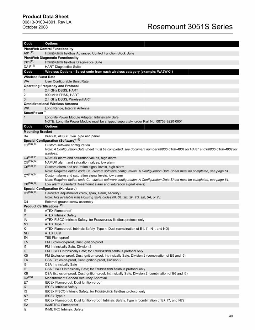
Product Data Sheet00813-0100-4801, Rev LA
October 2008 Rosemount 3051S Series
49
Code Options
PlantWeb Control Functionality
A01(11) FOUNDATION fieldbus Advanced Control Function Block Suite
PlantWeb Diagnostic Functionality
D01(11) FOUNDATION fieldbus Diagnostics Suite
DA1(12) HART Diagnostics Suite
Code Wireless Options - Select code from each wireless category (example: WA2WK1)
Wireless Burst Rate
WA User Configurable Burst Rate
Operating Frequency and Protocol
1 2.4 GHz DSSS, HART
2 900 MHz FHSS, HART
3 2.4 GHz DSSS, WirelessHART
Omnidirectional Wireless Antenna
WK Long Range, Integral Antenna
SmartPower™
1 Long-life Power Module Adapter, Intrinsically Safe
NOTE: Long-life Power Module must be shipped separately, order Part No. 00753-9220-0001.
Code Options
Mounting Bracket
B4 Bracket, all SST, 2-in. pipe and panel
Special Configuration (Software)(13)
C1(13)(14) Custom software configuration
Note: A Configuration Data Sheet must be completed, see document number 00806-0100-4801 for HART and 00806-0100-4802 for
wireless.
C4(13)(14) NAMUR alarm and saturation values, high alarm
C5(13)(14) NAMUR alarm and saturation values, low alarm
C6(13)(14) Custom alarm and saturation signal levels, high alarm
Note: Requires option code C1, custom software configuration. A Configuration Data Sheet must be completed, see page 61.
C7(13)(14) Custom alarm and saturation signal levels, low alarm
Note: Requires option code C1, custom software configuration. A Configuration Data Sheet must be completed, see page 61.
C8(13)(14) Low alarm (Standard Rosemount alarm and saturation signal levels)
Special Configuration (Hardware)
D1(13)(14) Hardware adjustments (zero, span, alarm, security)
Note: Not available with Housing Style codes 00, 01, 2E, 2F, 2G, 2M, 5A, or 7J.
D4 External ground screw assembly
Product Certifications(15)
E1 ATEX Flameproof
I1 ATEX Intrinsic Safety
IA ATEX FISCO Intrinsic Safety; for FOUNDATION fieldbus protocol only
N1 ATEX Type n
K1 ATEX Flameproof, Intrinsic Safety, Type n, Dust (combination of E1, I1, N1, and ND)
ND ATEX Dust
E4 TIIS Flameproof
E5 FM Explosion-proof, Dust Ignition-proof
I5 FM Intrinsically Safe, Division 2
IE FM FISCO Intrinsically Safe; for FOUNDATION fieldbus protocol only
K5 FM Explosion-proof, Dust Ignition-proof, Intrinsically Safe, Division 2 (combination of E5 and I5)
E6 CSA Explosion-proof, Dust Ignition-proof, Division 2
I6 CSA Intrinsically Safe
IF CSA FISCO Intrinsically Safe; for FOUNDATION fieldbus protocol only
K6 CSA Explosion-proof, Dust Ignition-proof, Intrinsically Safe, Division 2 (combination of E6 and I6)
D3(16) Measurement Canada Accuracy Approval
E7 IECEx Flameproof, Dust Ignition-proof
I7 IECEx Intrinsic Safety
IG IECEx FISCO Intrinsic Safety; for FOUNDATION fieldbus protocol only
N7 IECEx Type n
K7 IECEx Flameproof, Dust Ignition-proof, Intrinsic Safety, Type n (combination of E7, I7, and N7)
E2 INMETRO Flameproof
I2 INMETRO Intrinsic Safety

Product Data Sheet00813-0100-4801, Rev LA
October 2008Rosemount 3051S Series
K2 INMETRO Flameproof, Intrinsic Safety
E3(17) China Flameproof
I3(17) China Intrinsic Safety
KA ATEX and CSA Flameproof, Intrinsically Safe, Division 2 (combination of E1, E6, I1, and I6)
Note: Only available on Housing Style codes 00, IA, IJ, 2A, 2J, 2E, or 2M.
KB FM and CSA Explosion-proof, Dust Ignition-proof, Intrinsically Safe, Division 2 (combination of E5, E6, I5, and I6)
Note: Only available on Housing Style codes 00, IA, IJ, 2A, 2J, 2E, or 2M.
KC FM and ATEX Explosion-proof, Intrinsically Safe, Division 2 (combination of E5, E1, I5, and I1)
Note: Only available on Housing Style codes 00, IA, IJ, 2A, 2J, 2E, or 2M.
KD FM, CSA, and ATEX Explosion-proof, Intrinsically Safe (combination of E5, E6, E1, I5, I6, and I1)
Note: Only available on Housing Style codes 00, IA, IJ, 2A, 2J, 2E, or 2M.
DW(18) NSF Drinking Water Approval
Alternate Materials of Construction
L1 Inert sensor fill fluid Note: Silicone fill fluid is standard.
Digital Display(19)
M5 PlantWeb LCD Display
M7(14)(20) Remote mount LCD display and interface, no cable; PlantWeb housing, SST bracket, requires 4-20 mA / HART output
Note: See the 3051S Reference Manual (document number 00809-0100-4801) for cable requirements.
Contact an Emerson Process Management representative for additional information.
M8(14)(20)(21) Remote mount LCD display and interface, 50 ft. (15 m) cable; PlantWeb housing, SST bracket, requires 4-20 mA / HART output
M9(14)(20)(21) Remote mount LCD display and interface, 100 ft. (31 m) cable; PlantWeb housing, SST bracket, requires 4-20 mA / HART output
Special Procedures
P1 Hydrostatic testing with certificate
P2(22) Cleaning for special services
P3(22) Cleaning for less than 1 PPM chlorine/fluorine
Special Certifications
Q4 Calibration certificate
QP Calibration certificate and tamper evident seal
Q8 Material traceability certification per EN 10204 3.1.B
QS(13)(14) Prior-use certificate of FMEDA Data
QT(23) Safety-certified to IEC 61508 with certificate of FMEDA data
Q16 Surface finish certification for sanitary remote seals
QZ Remote Seal System Performance Calculation Report
Terminal Blocks
T1(24) Transient terminal block
T2(25) Terminal block with WAGO® spring clamp terminals
T3(25) Transient terminal block with WAGO spring clamp terminals
Conduit Electrical Connector
GE(26) M12, 4-pin, Male Connector (eurofast®)
GM(26) A size Mini, 4-pin, Male Connector (minifast®)
Typical Model Number: 3051S1TG 2A 2 E11 A 1A DA1 B4 M5
(1) Not available with Wireless Operating Frequency and Protocol option codes 1 or 2.
(2) Materials of Construction comply with metallurgical requirements highlighted within NACE MR0175/ISO 15156 for sour oil field production environments. Environmental limits apply to certain materials. Consult latest standard for details. Selected materials also conform to NACE MR0103 for sour refining environments.
(3) “Assemble to” items are specified separately and require a completed model number.
(4) Contact an Emerson Process Management representative for performance specifications.
(5) For spare SuperModule Platforms, select output code A.
(6) Requires PlantWeb housing.
(7) Available approvals are FM Intrinsically Safe, Division 2 (option code I5), CSA Intrinsically Safe (option code I6), ATEX Intrinsic Safety (option code I1; only available with 2.4 GHz), and IECEx Intrinsic Safety (option code I7; only available with 2.4 GHz).
(8) Material specified is cast as follows: CF-3M is the cast version of 316L SST. For housing, material is aluminum with polyurethane paint.
(9) Available with output code A only. Not available with approvals. See Rosemount 753R Product Data Sheet, 00813-0100-4379, to specify Web-Based Monitoring Indicator. Does not integrate into plant host systems.
(10) Available with output code A only. Available approvals are FM Intrinsically Safe, Division 2 (option code I5), ATEX Intrinsic Safety (option code I1), or IECEx Intrinsic Safety (option code I7). Contact an Emerson Process Management representative for additional information.
(11) Requires PlantWeb housing and output code F.
50

Product Data Sheet00813-0100-4801, Rev LA
October 2008 Rosemount 3051S Series
(12) Requires PlantWeb housing and output code A. Includes Hardware Adjustments as standard. Not available with option code QT.
(13) Not available with output code F or Housing code 01.
(14) Not available with output code X.
(15) Valid when SuperModule Platform and housing have equivalent approvals.
(16) Requires PlantWeb housing and Hardware Adjustments option code D1. Limited availability depending on transmitter type and range. Contact an Emerson Process Management representative for additional information.
(17) Contact an Emerson Process Management representative for availability.
(18) Requires 316L SST diaphragm material and Process Connection code E11 or G11.
(19) Not available with Housing code 01 and 7J.
(20) Not available with output code F, Housing code 01, option code DA1, or option code QT.
(21) Cable supplied is Belden 3084A, rated for ambient temperatures up to 167°F (75°C).
(22) Not available with process connection option code A11.
(23) Not available with output code F or X. Not available with housing code 01 or 7J.
(24) Not available with Housing code 00, 01, 5A, or 7J.
(25) Available with output code A and PlantWeb housing only.
(26) Not available with Housing code 00, 01, 5A, or 7J. Available with Intrinsically Safe approvals only. For FM Intrinsically Safe, Division 2 (option code I5) or FM FISCO Intrinsically Safe (option code IE), install in accordance with Rosemount drawing 03151-1009 to maintain outdoor rating (NEMA 4X and IP66).
51

Product Data Sheet00813-0100-4801, Rev LA
October 2008Rosemount 3051S Series
52
Rosemount 3051S Liquid Level TransmitterSelect either FF diaphragm seal type (see "Flush Flanged Seal" on page 53) or for EF diaphragm seal type (see "Extended Flanged
Seal" on page 54) and then finish this selection by choosing transmitter options.
Model Transmitter Type
3051S Liquid Level Transmitter
Code Performance Class
1(1) Ultra: 0.065% span accuracy, 100:1 rangedown, 12-year limited warranty
2 Classic: 0.065% span accuracy, 100:1 rangedown
Code Connection Type
L Level
Code Measurement Type
D Differential
G Gage
A Absolute
Code Pressure Range
Differential (LD) Gage (LG) Absolute (LA)
1A -25 to 25 inH2O (-62,2 to 62,2 mbar) -25 to 25 inH2O (-62,2 to 62,2 mbar) 0 to 30 psia (2,1 bar)
2A -250 to 250 inH2O (-623 to 623 mbar) -250 to 250 inH2O (-623 to 623 mbar) 0 to 150 psia (10 bar)
3A -1000 to 1000 inH2O (-2,5 to 2,5 bar) -393 to 1000 inH2O (-0,98 to 2,5 bar) 0 to 800 psia (55 bar)
4A -300 to 300 psi (-20,7 to 20,7 bar) -14.2 to 300 psig (-0,98 to 21 bar) 0 to 4000 psia (276 bar)
5A -2000 to 2000 psi (-137,9 to 137,9 bar) -14.2 to 2000 psig (-0,98 to 137,9 bar) N/A
Code Output(2)
A 4-20 mA with digital signal based on HART protocol
F(3) FOUNDATION fieldbus protocol
X(4) Wireless (Requires wireless options and wireless housing 5A)
Code Housing Style Material(5) Conduit Entry
00 None (SuperModule Platform only, no housing included)
01(6) Assemble to Rosemount 753R Web-Based Monitoring Indicator
1A PlantWeb housing Aluminum 1/2–14 NPT
1B PlantWeb housing Aluminum M20 x 1.5 (CM20)
1C PlantWeb housing Aluminum G1/2
1J PlantWeb housing SST 1/2–14 NPT
1K PlantWeb housing SST M20 x 1.5 (CM20)
1L PlantWeb housing SST G1/2
5A Wireless PlantWeb housing Aluminum 1/2–14 NPT
5J Wireless PlantWeb housing SST 1/2–14 NPT
2A Junction Box housing Aluminum 1/2–14 NPT
2B Junction Box housing Aluminum M20 x 1.5 (CM20)
2C Junction Box housing Aluminum G1/2
2J Junction Box housing SST 1/2–14 NPT
2E Junction Box with output for remote interface Aluminum 1/2–14 NPT
2F Junction Box with output for remote interface Aluminum M20 x 1.5 (CM20)
2G Junction Box with output for remote interface Aluminum G1/2
2M Junction Box with output for remote interface SST 1/2–14 NPT
7J(7) Quick Connect (A size Mini, 4-pin male termination) SST
Code Seal System Type
1 Direct-mount diaphragm seal system
Code High Pressure Side Extension (between transmitter flange and seal)
0 Direct-mount (No extension)
Code Low Pressure Side Connection (sensor module)
1 One capillary connection remote diaphragm seal (see Rosemount 1199 ordering table for seal information)
2 316L SST isolator / SST transmitter flange
3 Alloy C-276 isolator / SST transmitter flange
Code Capillary Length
0 N/A
Code Diaphragm Seal Fill Fluid
A Syltherm XLT
C D. C. Silicone 704
D D. C. Silicone 200
H Inert (Halocarbon)
G Glycerine and Water
N Neobee M-20
P Propylene Glycol and Water
Next, select either Flush Flanged (FF) diaphragm seal (see page 53) or
Extended Flanged (EF) diaphragm seal (see page 54).

Product Data Sheet00813-0100-4801, Rev LA
October 2008 Rosemount 3051S Series
53
Seal Options (page 53—54)Flush Flanged Seal
Code(1)
(2)
(1) Not available with Wireless Operating Frequency and Protocol option codes 1 or 2.
(2) For spare SuperModule Platforms, select output code A.
Process Connection Style(3)
(3) Requires PlantWeb housing.
FF Flush Flanged, Ra 125-250 gasket surface
Code(4)
(4) Available approvals are FM Intrinsically Safe, Division 2 (option code I5), CSA Intrinsically Safe (option code I6), ATEX Intrinsic Safety (option code I1; only available with 2.4 GHz), and IECEx Intrinsic Safety (option code I7; only available with 2.4 GHz).
Diaphragm Seal Size (High Side)
G 2-in./DN 50
7 3-in.
J DN 80
9 4-in./DN 100
Code Flange Rating (High Side)
1 Class 150
2 Class 300
4 Class 600
G PN 40
E PN 10/16; available with 4 in. DN 100 only
Code Isolator Material (5)
(5) Material specified is cast as follows: CF-3M is the cast version of 316L SST. For housing, material is aluminum with polyurethane paint.
Flange Material (High Side)(6)(7)
(6) Available with output code A only. Not available with approvals. See Rosemount 753R Product Data Sheet, 00813-0100-4379, to specify Web-Based Monitoring Indicator. Does not integrate into plant host systems.
(7) Available with output code A only. Available approvals are FM Intrinsically Safe, Division 2 (option code I5), ATEX Intrinsic Safety (option code I1), or IECEx Intrinsic Safety (option code I7). Contact an Emerson Process Management representative for additional information.
CA 316L SST CS
DA 316L SST SST
CB Alloy C-276 CS
DB Alloy C-276 SST
CC Tantalum - seam welded(8)
(8) Not recommended for use with spiral wound metallic gaskets (see 1199 product data sheet, document 00813-0100-4016 for additional options).
CS
DC Tantalum - seam welded(8) SST
Code Lower Housing Material (High Side)(9)
(9) Standard gasket for lower housing consists of non-asbestos fiber.
0 None
A 316 SST
B Alloy C-276
Code Flushing Connection Quantity and Size (Lower Housing, High Side)
0 None
1 1 (1/4-in.)
3 2 (1/4-in.)
7 1 (1/2-in.)
9 2 (1/2-in.)
Code Seal Options: Flushing Connections
SD Alloy C-276 Plug in Flushing Connection
SG 316 SST Plug in Flushing Connection
SH 316 SST Vent/Drain Valve in Flushing Connection
Code Seal Options: Gaskets
SJ PTFE gasket for lower housing
SK Gylon gasket for lower housing
SN Grafoil™ gasket for lower housing
Code Other Options
ST(10)
(10) Materials of Construction comply with metallurgical requirements highlighted within NACE MR0175/ISO 15156 for sour oil field production environments. Environmental limits apply to certain materials. Consult latest standard for details. Selected materials also conform to NACE MR0103 for sour refining environments.
Materials per NACE MR0175/ISO 15156, MR0103
Continue with transmitter options on page 54

Product Data Sheet00813-0100-4801, Rev LA
October 2008Rosemount 3051S Series
54
Extended Flanged Seal
Transmitter Options continued from page 52(— = Not Applicable • = Applicable)
Code Process Connection Style
EF Extended flanged, Ra 125-250 gasket surface
Code Diaphragm Seal Size (High Side)
7 3-in./DN 80, 2.58-in. diaphragm
9 4-in./DN 100, 3.5-in. diaphragm
Code Flange Rating (High Side)
1 Class 150
2 Class 300
4 Class 600
G PN 40
E PN 10/16; available with 4 in. DN 100 only
Code Isolator Material and Extension Material Flange Material (High Side)
CA 316L SST CS
DA 316L SST SST
CB Alloy C-276 / Cast C-276 CS
DB Alloy C-276 / Cast C-276 SST
Code Extension Length (High Side, 1st Position)
2 2-in./50 mm
4 4-in./100 mm
6 6-in./150 mm
Code Extension Length (High Side, 2nd Position)
0 0-in./0 mm
Continue with transmitter options below
Code Options
PlantWeb Control Functionality
A01(1) FOUNDATION fieldbus Advanced Control Function Block Suite
PlantWeb Diagnostic Functionality
D01(1) FOUNDATION fieldbus Diagnostics Suite
DA1(2) HART Diagnostics Suite
Code Wireless Options - Select code from each wireless category (example: WA2WK1)
Wireless Burst Rate
WA User Configurable Burst Rate
Operating Frequency and Protocol
1 2.4 GHz DSSS, HART
2 900 MHz FHSS, HART
3 2.4 GHz DSSS, WirelessHART
Omnidirectional Wireless Antenna
WK Long Range, Integral Antenna
SmartPower™
1 Long-life Power Module Adapter, Intrinsically Safe
NOTE: Long-life Power Module must be shipped separately, order Part No. 00753-9220-0001.
Code Options
Special Configuration (Software)
C1(3) Custom software configuration
Note: A Configuration Data Sheet must be completed, see document number 00806-0100-4801 for HART and
00806-0100-4802 for wireless.
C3 Gage pressure calibration on Rosemount 3051S_LA4 only
C4(3)(4) NAMUR alarm and saturation levels, high alarm
C5(3)(4) NAMUR alarm and saturation levels, low alarm
C6(3)(4) Custom alarm and saturation signal levels, high alarm
Note: Requires option code C1, custom software configuration. A Configuration Data Sheet must be completed, see document number 00806-0100-4801.

Product Data Sheet00813-0100-4801, Rev LA
October 2008 Rosemount 3051S Series
C7(3)(4) Custom alarm and saturation signal levels, low alarm
Note: Requires option code C1, custom software configuration. A Configuration Data Sheet must be completed, see document number 00806-0100-4801.
C8(3)(4) Low alarm (standard Rosemount alarm and saturation levels)
Special Configuration (hardware) LD LG LA
D1(3)(4) Hardware adjustments (zero, span, alarm, security)
Note: Not available with fieldbus protocol or Housing Style codes 00, 01, 2E, 2F, 2G, 2M, 5A, or 7J.
• • •
D2 1/2-14 NPT process connections process adapters • — —
D4 External ground screw assembly • • •
D5 Delete transmitter drain/vent valves (install plugs) • — —
D8 Ceramic drain/vent valves • — —
D9 RC 1/2 process connections (process adapters) • — —
Product Certifications(5)
E1 ATEX Flameproof
I1 ATEX Intrinsic Safety
IA ATEX FISCO Intrinsic Safety; for FOUNDATION fieldbus protocol only
N1 ATEX Type n
K1 ATEX Flameproof, Intrinsic Safety, Type n, Dust (combination of E1, I1, N1, and ND)
ND ATEX Dust
E4 TIIS Flameproof
E5 FM Explosion-proof, Dust Ignition-proof
I5 FM Intrinsically Safe, Division 2
IE FM FISCO Intrinsically Safe; for FOUNDATION fieldbus protocol only
K5 FM Explosion-proof, Dust Ignition-proof, Intrinsically Safe, Division 2 (combination of E5 and I5)
E6 CSA Explosion-proof, Dust Ignition-proof, Division 2
I6 CSA Intrinsically Safe
IF CSA FISCO Intrinsically Safe; for FOUNDATION fieldbus protocol only
K6 CSA Explosion-proof, Dust Ignition-proof, Intrinsically Safe, Division 2 (combination of E6 and I6)
D3(6) Measurement Canada Accuracy Approval
E7 IECEx Flameproof, Dust Ignition-proof
I7 IECEx Intrinsic Safety
IG IECEx FISCO Intrinsic Safety; for FOUNDATION fieldbus protocol only
N7 IECEx Type n
K7 IECEx Flameproof, Dust Ignition-proof, Intrinsic Safety, Type n (combination of E7, I7, and N7)
E2 INMETRO Flameproof
I2 INMETRO Intrinsic Safety
K2 INMETRO Flameproof, Intrinsic Safety
E3(7) China Flameproof
I3(7) China Intrinsic Safety
KA ATEX and CSA Flameproof, Intrinsically Safe, Division 2 (combination of E1, E6, I1, and I6)
Note: Only available on Housing Style codes 00, IA, IJ, 2A, 2J, 2E, or 2M.
KB FM and CSA Explosion-proof, Dust Ignition-proof, Intrinsically Safe, Division 2 (combination of E5, E6, I5, and I6)
Note: Only available on Housing Style codes 00, IA, IJ, 2A, 2J, 2E, or 2M.
KC FM and ATEX Explosion-proof, Intrinsically Safe, Division 2 (combination of E5, E1, I5, and I1)
Note: Only available on Housing Style codes 00, IA, IJ, 2A, 2J, 2E, or 2M.
KD FM, CSA, and ATEX Explosion-proof, Intrinsically Safe (combination of E5, E6, E1, I5, I6, and I1)
Note: Only available on Housing Style codes 00, IA, IJ, 2A, 2J, 2E, or 2M.
Alternate Materials of Construction
L1 Inert sensor fill fluid (differential and gage only)
Note: Silicone fill fluid is standard.
L2 Graphite-filled PTFE o-ring
L4 Austenitic 316 SST bolts
L5(8) ASTM A193, Grade B7M bolts
L6 Alloy K-500 bolts
L7(8) ASTM A453, Class D, Grade 660 bolts
L8 ASTM A193, Class 2, Grade B8M bolts
Digital Display(9)
M5 PlantWeb LCD Display
M7(4)(10) Remote mount LCD display and interface, no cable; PlantWeb housing, SST bracket, requires 4-20 mA / HART output
Note: See the 3051S Reference Manual (document number 00809-0100-4801) for cable requirements.
Contact an Emerson Process Management representative for additional information.
M8(4)(10)(11) Remote mount LCD display and interface, 50 ft. (15 m) cable; PlantWeb housing, SST bracket, requires 4-20 mA / HART output
55

Product Data Sheet00813-0100-4801, Rev LA
October 2008Rosemount 3051S Series
M9(4)(10)(11) Remote mount LCD display and interface, 100 ft. (31 m) cable; PlantWeb housing, SST bracket, requires 4-20 mA / HART output
Special Procedures
P1 Hydrostatic testing with certificate
P2 Cleaning for special services
P3 Cleaning for less than 1PPM chlorine/fluorine
Special Certifications
Q4 Calibration certificate
QP Calibration certificate and tamper evident seal
Q8 Material traceability certification per EN 10204 3.1.B
QS(3)(4) Prior-use certificate of FMEDA Data
QT(12) Safety-certified to IEC 61508 with certificate of FMEDA data
QZ Remote Seal System Performance Calculation Report
Terminal blocks
T1(13) Transient terminal block
T2(14) Terminal block with WAGO® spring clamp terminals
T3(14) Transient terminal block with WAGO spring clamp terminals
Conduit Electrical Connector
GE(15) M12, 4-pin, Male Connector (eurofast®)
GM(15) A size Mini, 4-pin, Male Connector (minifast®)
Typical Model Number for FF seal: 3051S2LD 2A A 1A 1 0 2 0 D FF 7 1 DA 0 0
Typical Model Number for EF seal: 3051S2LD 2A A 1A 1 0 2 0 D EF 7 1 DA 2 0
(1) Requires PlantWeb housing and output code F.
(2) Requires PlantWeb housing and output code A. Includes Hardware Adjustments as standard. Not available with option code QT.
(3) Not available with output code F or Housing code 01.
(4) Not available with output code X.
(5) Valid when SuperModule Platform and housing have equivalent approvals.
(6) Requires PlantWeb housing and Hardware Adjustments option code D1. Limited availability depending on transmitter type and range. Contact an Emerson Process Management representative for additional information.
(7) Contact an Emerson Process Management representative for availability.
(8) Materials of Construction comply with metallurgical requirements highlighted within NACE MR0175/ISO 15156 for sour oil field production environments. Environmental limits apply to certain materials. Consult latest standard for details. Selected materials also conform to NACE MR0103 for sour refining environments.
(9) Not available with Housing Code 01 or 7J.
(10) Not available with output code F, Housing code 01, option code DA1, or option code QT.
(11) Cable supplied is Belden 3084A, rated for ambient temperatures up to 167°F (75°C).
(12) Not available with output code F or X. Not available with housing code 01 or 7J.
(13) Not available with Housing code 00, 01, 5A, or 7J.
(14) Available with output code A and PlantWeb housing only.
(15) Not available with Housing code 00, 01, 5A, or 7J. Available with Intrinsically Safe approvals only. For FM Intrinsically Safe, Division 2 (option code I5) or FM FISCO Intrinsically Safe (option code IE), install in accordance with Rosemount drawing 03151-1009 to maintain outdoor rating (NEMA 4X and IP66).
56

Product Data Sheet00813-0100-4801, Rev LA
October 2008 Rosemount 3051S Series
Rosemount 300S MultiVariable Transmitter Housing KitModel
300SMV Housing Kit for Rosemount 3051S MultiVariable Transmitter
Code MultiVariable Type
M MultiVariable Measurement with Fully Compensated Mass and Energy Flow
P MultiVariable Measurement with Direct Process Variable Output
Code Temperature Input
N None
R(1) RTD Input (Type Pt 100, -328 to 1562 °F (-200 to 850 °C))
Code Transmitter Output
A 4–20 mA with digital signal based on HART protocol
Code Housing Style Material(2) Conduit Entry
1A PlantWeb housing Aluminum 1/2–14 NPT
1B PlantWeb housing Aluminum M20 x 1.5 (CM20)
1C PlantWeb housing Aluminum G1/2
1J PlantWeb housing SST 1/2–14 NPT
1K PlantWeb housing SST M20 x 1.5 (CM20)
1L PlantWeb housing SST G 1/2
Code Options
RTD Cable (RTD Sensor must be ordered separately)
C12 RTD Input with 12 ft. (3.66 m) of Shielded Cable
C13 RTD Input with 24 ft. (7.32 m) of Shielded Cable
C14 RTD Input with 75 ft. (22.86 m) of Shielded Cable
C20(3) RTD Input with 27 in. (69 cm) of Armored Shielded Cable
C21 RTD Input with 4 ft. (1.22 m) of Armored Shielded Cable
C22 RTD Input with 12 ft. (3.66 m) of Armored Shielded Cable
C23 RTD Input with 24 ft. (7.32 m) of Armored Shielded Cable
C24 RTD Input with 75 ft. (22.86 m) of Armored Shielded Cable
C30(3) RTD Input with 25 in. (64 cm) of ATEX/IECEx Flameproof Cable
C32 RTD Input with 12 ft. (3.66 m) of ATEX/IECEx Flameproof Cable
C33 RTD Input with 24 ft. (7.32 m) of ATEX/IECEx Flameproof Cable
C34 RTD Input with 75 ft. (22.86 m) of ATEX/IECEx Flameproof Cable
C40(3) RTD Input with 34 in. (86.36 cm) Shielded Cable and 24 in. (60.96 cm) FM Approved Coupling Flex
C41(3) RTD Input with 40 in. (101.60 cm) Shielded Cable and 30 in. (76.20 cm) FM Approved Coupling Flex
Software Configuration
C1(4) Custom software configuration
Note: A Configuration Data Sheet must be completed, see document number 00806-0100-4803.
C2(4) Custom flow configuration
Note: A Custom Fluid Data Sheet must be completed, see document number 00806-0200-4803.
Alarm Limit
C4 NAMUR alarm and saturation levels, high alarm
C5 NAMUR alarm and saturation levels, low alarm
C6(4) Custom alarm and saturation signal levels, high alarm
C7(4) Custom alarm and saturation signal levels, low alarm
C8 Low alarm (standard Rosemount alarm and saturation levels)
External Ground Screw Assembly
D4 External Ground Screw Assembly
Product Certifications
E1 ATEX Flameproof
I1 ATEX Intrinsic Safety
N1 ATEX Type n
ND ATEX Dust
K1 ATEX Flameproof, Intrinsic Safety, Type n, Dust (combination of E1, I1, N1, and ND)
E4 TIIS Flameproof
I4 TIIS Intrinsic Safety
K4 TIIS Flameproof and Intrinsic Safety (combination E4 and I4)
E5 FM Explosion-proof, Dust Ignition-proof
57

Product Data Sheet00813-0100-4801, Rev LA
October 2008Rosemount 3051S Series
I5 FM Intrinsically Safe, Division 2
K5 FM Explosion-proof, Dust Ignition-proof, Intrinsically Safe, Division 2 (combination of E5 and I5)
E6 CSA Explosion-proof, Dust Ignition-proof, Division 2
I6 CSA Intrinsically Safe
K6 CSA Explosion-proof, Dust Ignition-proof, Intrinsically Safe, Division 2 (combination of E6 and I6)
E7 IECEx Flameproof, Dust Ignition-proof
I7 IECEx Intrinsic Safety
N7 IECEx Type n
K7 IECEx Flameproof, Dust Ignition-proof, Intrinsic Safety, Type n (combination of E7, I7, and N7)
E2(4) INMETRO Flameproof
I2(4) INMETRO Intrinsic Safety
K2(4) INMETRO Flameproof, Intrinsic Safety (combination of E2 and I2)
E3(4) China Flameproof
I3(4) China Intrinsic Safety
KA(5) ATEX and CSA Explosion-proof, Intrinsically Safe, Division 2 (combination of E1, E6, I1, and I6)
KB FM and CSA Explosion-proof, Dust Ignition-proof, Intrinsically Safe, Division 2 (combination of E5, E6, I5, and I6)
KC(5) FM and ATEX Explosion-proof, Intrinsically Safe, Division 2 (combination of E5, E1, I5, and I1)
KD(5) FM, CSA, and ATEX Explosion-proof, Intrinsically Safe (combination of E5, E6, E1, I5, I6, and I1)
Digital Display
M5 PlantWeb LCD Display
Calibration Data Certification
Q4(4)(6) Calibration Certificate
QP(4) Calibration Certificate and Tamper Evident Seal
Terminal Blocks
T1 Transient terminal block
Conduit Electrical Connector
GE(7) M12, 4-pin, Male Connector (eurofast®)
GM(7) A size Mini, 4-pin, Male Connector (minifast®)
Typical Model Number: 300SMV M R 1A C22 M5
(1) RTD Sensor must be ordered separately.
(2) Material specified is cast as follows: CF-8M is the cast version of 316 SST, CF-3M is the cast version of 316L SST, CW-12MW is the cast version of Alloy C-276, M-30C is the cast version of Alloy 400. For housing, material is aluminum with polyurethane paint.
(3) For use with Flowmeters with integral RTDs.
(4) Contact an Emerson Process Management representative for availability.
(5) RTD cable not available with this option.
(6) Calibration certificate only provides data for process temperature RTD interface.
(7) Available with Intrinsically Safe approvals only. For FM Intrinsically Safe, Non-Incendive approval (option code I5), install in accordance with Rosemount drawing 03151-1206 to maintain outdoor rating (NEMA 4X and IP66).
58

Product Data Sheet00813-0100-4801, Rev LA
October 2008 Rosemount 3051S Series
Rosemount 300S Series Housing Kit
Model
300S Housing Kit for Rosemount 3051S Coplanar, In-Line, and Liquid Level Transmitters
Code Housing Style Material(1) Conduit Entry
1A PlantWeb housing Aluminum 1/2–14 NPT
1B PlantWeb housing Aluminum M20 x 1.5 (CM20)
1C PlantWeb housing Aluminum G1/2
1J PlantWeb housing SST 1/2–14 NPT
1K PlantWeb housing SST M20 x 1.5 (CM20)
1L PlantWeb housing SST G 1/2
2A Junction Box housing Aluminum 1/2–14 NPT
2B Junction Box housing Aluminum M20 x 1.5 (CM20)
2C Junction Box housing Aluminum G1/2
2J Junction Box housing SST 1/2–14 NPT
2E Junction Box housing with output for remote interface Aluminum 1/2–14 NPT
2F Junction Box housing with output for remote interface Aluminum M20 x 1.5 (CM20)
2G Junction Box housing with output for remote interface Aluminum G1/2
2M Junction Box housing with output for remote interface SST 1/2–14 NPT
3A Remote mount display and interface housing Aluminum 1/2–14 NPT
3B Remote mount display and interface housing Aluminum M20 x 1.5 (CM20)
3C Remote mount display and interface housing Aluminum G1/2
3J Remote mount display and interface housing SST 1/2–14 NPT
7J(2) Quick Connect (A size Mini, 4-pin male termination) SST
Code Output
A 4-20 mA with digital signal based on HART protocol
F(3) FOUNDATION fieldbus protocol
Code Options
PlantWeb Control Functionality
A01(4) FOUNDATION fieldbus Advanced Control Function Block Suite
PlantWeb Diagnostic Functionality
D01(4) FOUNDATION fieldbus Diagnostics Suite
DA1(5) HART Diagnostics Suite
Special Configuration (Hardware)
D1(6) Hardware adjustments (zero, span, alarm, security)
Note: Not available with Housing Style codes 2E, 2F, 2G, 2M, 3A, 3B, 3C, 3J, or 7J.
Product Certifications
E1 ATEX Flameproof
I1 ATEX Intrinsic Safety
IA ATEX FISCO Intrinsic Safety; for FOUNDATION fieldbus protocol only
N1 ATEX Type n
K1 ATEX Flameproof, Intrinsic Safety, Type n, Dust (combination of E1, I1, N1, and ND)
ND ATEX Dust
E5 FM Explosion-proof, Dust Ignition-proof
I5 FM Intrinsically Safe, Division 2
IE FM FISCO Intrinsically Safe; for FOUNDATION fieldbus protocol only
K5 FM Explosion-proof, Dust Ignition-proof, Intrinsically Safe, Division 2 (combination of E5 and I5)
E6 CSA Explosion-proof, Dust Ignition-proof, Division 2
I6 CSA Intrinsically Safe
IF CSA FISCO Intrinsically Safe; for FOUNDATION fieldbus protocol only
K6 CSA Explosion-proof, Dust Ignition-proof, Intrinsically Safe, Division 2 (combination of E6 and I6)
E7 IECEx Flameproof, Dust Ignition-proof
I7 IECEx Intrinsic Safety
IG IECEx FISCO Intrinsic Safety; for FOUNDATION fieldbus protocol only
N7 IECEx Type n
K7 IECEx Flameproof, Dust Ignition-proof, Intrinsic Safety, Type n (combination of E7, I7, and N7)
E2 INMETRO Flameproof
I2 INMETRO Intrinsic Safety
59
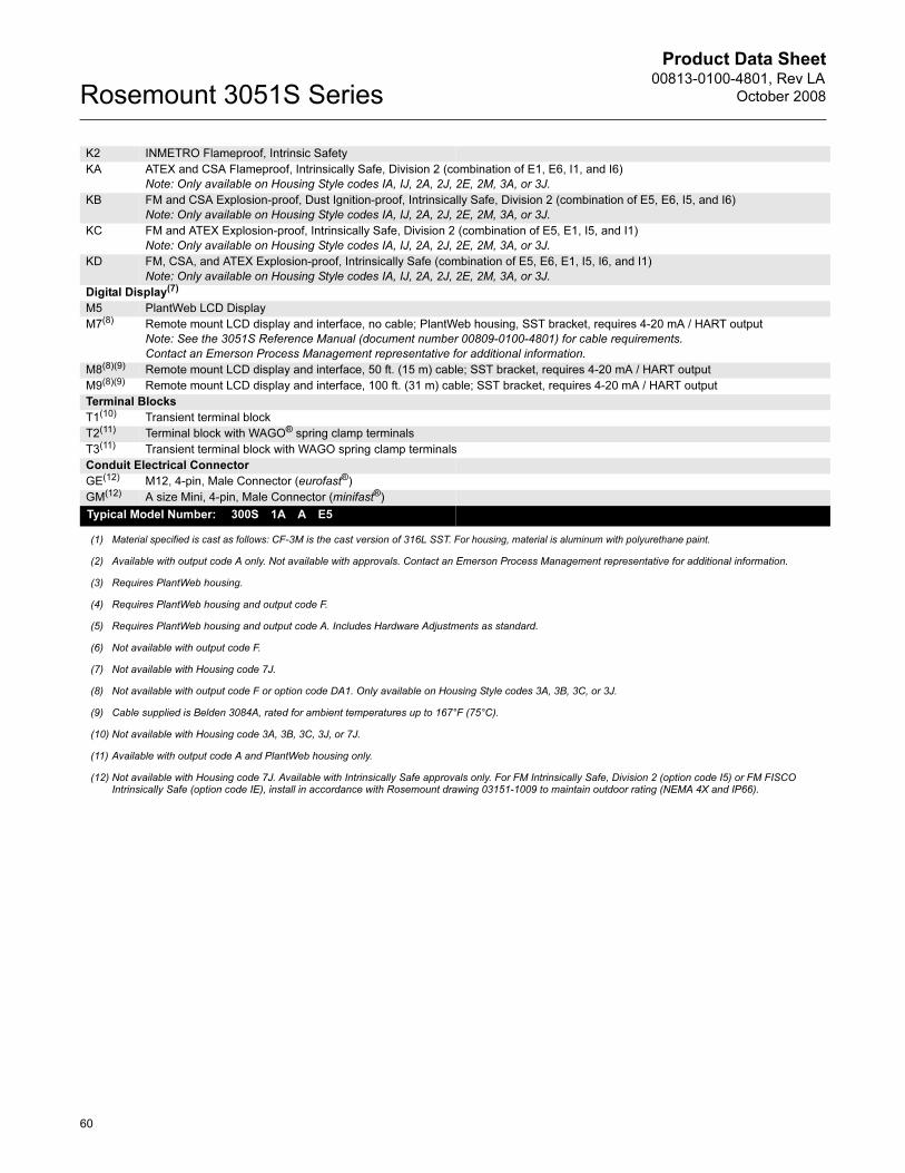
Product Data Sheet00813-0100-4801, Rev LA
October 2008Rosemount 3051S Series
K2 INMETRO Flameproof, Intrinsic Safety
KA ATEX and CSA Flameproof, Intrinsically Safe, Division 2 (combination of E1, E6, I1, and I6)
Note: Only available on Housing Style codes IA, IJ, 2A, 2J, 2E, 2M, 3A, or 3J.
KB FM and CSA Explosion-proof, Dust Ignition-proof, Intrinsically Safe, Division 2 (combination of E5, E6, I5, and I6)
Note: Only available on Housing Style codes IA, IJ, 2A, 2J, 2E, 2M, 3A, or 3J.
KC FM and ATEX Explosion-proof, Intrinsically Safe, Division 2 (combination of E5, E1, I5, and I1)
Note: Only available on Housing Style codes IA, IJ, 2A, 2J, 2E, 2M, 3A, or 3J.
KD FM, CSA, and ATEX Explosion-proof, Intrinsically Safe (combination of E5, E6, E1, I5, I6, and I1)
Note: Only available on Housing Style codes IA, IJ, 2A, 2J, 2E, 2M, 3A, or 3J.
Digital Display(7)
M5 PlantWeb LCD Display
M7(8) Remote mount LCD display and interface, no cable; PlantWeb housing, SST bracket, requires 4-20 mA / HART output
Note: See the 3051S Reference Manual (document number 00809-0100-4801) for cable requirements.
Contact an Emerson Process Management representative for additional information.
M8(8)(9) Remote mount LCD display and interface, 50 ft. (15 m) cable; SST bracket, requires 4-20 mA / HART output
M9(8)(9) Remote mount LCD display and interface, 100 ft. (31 m) cable; SST bracket, requires 4-20 mA / HART output
Terminal Blocks
T1(10) Transient terminal block
T2(11) Terminal block with WAGO® spring clamp terminals
T3(11) Transient terminal block with WAGO spring clamp terminals
Conduit Electrical Connector
GE(12) M12, 4-pin, Male Connector (eurofast®)
GM(12) A size Mini, 4-pin, Male Connector (minifast®)
Typical Model Number: 300S 1A A E5
(1) Material specified is cast as follows: CF-3M is the cast version of 316L SST. For housing, material is aluminum with polyurethane paint.
(2) Available with output code A only. Not available with approvals. Contact an Emerson Process Management representative for additional information.
(3) Requires PlantWeb housing.
(4) Requires PlantWeb housing and output code F.
(5) Requires PlantWeb housing and output code A. Includes Hardware Adjustments as standard.
(6) Not available with output code F.
(7) Not available with Housing code 7J.
(8) Not available with output code F or option code DA1. Only available on Housing Style codes 3A, 3B, 3C, or 3J.
(9) Cable supplied is Belden 3084A, rated for ambient temperatures up to 167°F (75°C).
(10) Not available with Housing code 3A, 3B, 3C, 3J, or 7J.
(11) Available with output code A and PlantWeb housing only.
(12) Not available with Housing code 7J. Available with Intrinsically Safe approvals only. For FM Intrinsically Safe, Division 2 (option code I5) or FM FISCO Intrinsically Safe (option code IE), install in accordance with Rosemount drawing 03151-1009 to maintain outdoor rating (NEMA 4X and IP66).
60

Product Data Sheet00813-0100-4801, Rev LA
October 2008 Rosemount 3051S Series
ACCESSORIES
Rosemount Engineering Assistant (EA)
Software Packages
The Rosemount Engineering Assistant software supports flow
configuration for the 3051S MultiVariable and 3051S FOUNDATION
fieldbus. The package is available with or without modem and
connecting cables. All configurations are packaged separately.
For best performance of the EA Software, the following computer
hardware and software is recommended:
• Pentium, 800MHz personal computer or above
• 512 MB RAM
• 350 MB of available hard disk space
• Microsoft ® Windows™ 2000 or XP Professional
Engineering Assistant Software Packages
Accessories
Code Product Description
EA Engineering Assistant Software Program
Code Software Media
2 EA Rev. 5 (Compatible with 3095, 3051S FOUNDATION
fieldbus, and 333)
3 EA Rev. 6 (Compatible with 3051SMV only)
Code Language
E English
Code Modem and Connecting Cables
O None
H Serial Port HART Modem and Cables
B USB Port HART Modem and Cables
C FOUNDATION fieldbus PCM-CIA Interface Card and Cables
Code License
N1 Single PC license
N2 Site license
Typical Model Number: EA 2 E O N1
Item Description Part Number
Serial Port HART Modem and Cables Only 03095-5105-0001
USB Port HART Modem and Cables Only(1)
(1) Supported by Snap-On EA with AMS Device Manager version 6.2 or higher.
03095-5105-0002
FOUNDATION fieldbus PCM-CIA Interface
Card and Cables Only
03095-5108-0001
Long-life Power Module for Wireless option 00753-9220-0001
61

Product Data Sheet00813-0100-4801, Rev LA
October 2008Rosemount 3051S Series
Standard Terms and Conditions of Sale can be found at www.rosemount.com/terms_of_saleThe Emerson logo is a trade mark and service mark of Emerson Electric Co. Rosemount, Annubar, SuperModule and the Rosemount logotype are registered trademarks of Rosemount Inc. PlantWeb is a mark of one of the Emerson Process Management companies. Instrument Toolkit, Saturn, MultiVariable and Coplanar are trademarks of Rosemount Inc. Eurofast and Minifast are registered trademarks of Turck Inc.
00813-0100-4801 Rev LA, 10/08
HART and WirelessHART are registered trademarks of the HART Communications Foundation. ASP is a trademark of the Emerson Process Management companies.Syltherm, Dow Corning, and D.C. are registered trademarks of Dow Corning Co. Neobee M-20 is a registered trademark of Stephan Chemical Co. FOUNDATION fieldbus is a trademark of the Fieldbus Foundation. WAGO is a registered trademark of WAGO KontakHechnik GmbH, Germany.All other marks are the property of their respective owners.© 2008 Rosemount, Inc. All rights reserved.
These 3051S products may be protected by one or more of the following: U.S. Patent Nos. 4466290; 4612812; 4866435; 4988990; 5083091; 5122794; 5166678; 5248167; 5287746; 5333504; 5585777; 5899962; 6017143; 6119047; 6182019; 6295875; 6457367; 6487912; 6568279; 6571132; 6609427; 6643610; 6658945; 6898980; Des. 439177; Des. 439178; Des. 439179; Des. 439180; Des. 439181; Des. 441672. May depend on model. Other U.S. and foreign patents issued and pending.
Emerson Process Management Blegistrasse 23P.O. Box 1046CH 6341 BaarSwitzerlandTel +41 (0) 41 768 6111Fax +41 (0) 41 768 6300
Emerson Process Management Asia Pacific Pte Ltd1 Pandan CrescentSingapore 128461Tel +65 6777 8211Fax +65 6777 0947Service Support Hotline : +65 6770 8711Email : [email protected]
Emerson Process ManagementRosemount Measurement8200 Market BoulevardChanhassen MN 55317 USATel (USA) 1 800 999 9307Tel (International) +1 952 906 8888Fax +1 952 949 7001
Emerson FZEP.O. Box 17033Jebel Ali Free ZoneDubai UAETel +971 4 811 8100Fax +971 4 886 5465