rostra cruise fitment (bmw k1200s and tips for other … cruise fitment (bmw k1200s and tips for...
TRANSCRIPT

Rostra Cruise Fitment (BMW K1200S and tips for other bikes)
Anyone who's ridden more than about an hour knows about wrist pain. Holding a throttle open against a fairly strong spring eventually creates wrist cramp. Even on the more tour-oriented bikes, there is no escape. In fact the forced forward lean to keep a hold of the throttle also generates lower back pain. Having a functional cruise you can sit more upright, reduce the forward lean, get a better view of your surroundings and give your right hand a much needed rest.
In the past I've tried throttle locks, and whilst they are of some benefit, their overall operation is poor at best. This is because as soon as you lock it, you need to adjust it, due to undulations in the road. Through the above suffering and frustration, and my background as an Electrical Engineer, I felt it was time to go one better and see if I could install a proper electronic cruise control.
Rostra (originally owned by Dana) make such a kit, which uses an electric servo, rather than the older Audiovox vacuum style kits. This in theory means the kit should be a little easier to install, and shouldn’t suffer as much speed hesitation and surge as the vacuum kits do. The kit costs around $300 depending on exactly which accessories you need, which I’ll discuss further below. Murphs Kits in the USA (www.murphskits.com) is a good place to source it at a reasonable price. He also sells the relays and a handy keypad controller mount.
This kit was originally designed to fit an automobile, not a motorcycle, so there are a few issues with the kit as supplied. First, the servo module is pretty large, which makes packaging within the bike a challenge. Second, the wiring is way too long, and includes non-waterproof connectors, but a cut and shut can fix these issues. Third the throttle linkage is quite challenging to sort out, but I have done the hard work for you. Fortunately none of these things are impossible to sort out.
This article shows how I installed the Rostra kit in the context of a BMW K1200S. The outcome should be generally applicable to most bikes, with some exceptions, mainly in the servo motor packaging, cable routing, throttle linkage, PPM setting, and wiring colour areas.
Let it be said that this is a potentially dangerous modification to make because there is the potential to inadvertently hold the throttle open, if your cruise cable catches on anything. This may lead to a fatal accident and/or damage of your or others’ property. It could kill you. There are other failure modes that could occur (I do not suggest I know all potential failure mechanisms nor consequences). Needless to say, if you follow anything within this document, you do so entirely at your own risk. You are completely on your OWN and I will not accept any liability as a result. This is merely a description of how I did it, and you may decide to do things differently. Please take care, perform quality work, test it thoroughly and seek professional help if/where needed. Enough said…on with the install…
MECHANICAL INSTALLATION
There are four main activities in this area: 1) Mounting the cruise control module; 2) Moving the PCV hose out of the way (particular to the K1200S installation); 3) Fabricating

the throttle linkage; 4) Cruise keypad mounting
First up, remove the side fairings, tank fairings, fuel tank (drain first if need be), battery, airbox and throttle bodies. Refer to your owners manual if required to locate the fasteners required. Note on the BMW, the band clamps used on the throttle bodies are a different size top to bottom, do not mix them. They can be flicked open and closed on the first latch before assembling the throttle bodies (and airbox) back to the bike, then easily cinched up the last ½" with multigrips. No special tools are needed.
Cruise Module Mounting
I tried packaging the cruise module next to the starter motor under the fuel tank, but it didn’t fit. You can get it in there if you moved out the coolant overflow reservoir, but note the access to the DIP switches (see later) becomes very difficult. Rather, it can be mounted to the rear side of the ZFE (central electronics) module which sits under the middle fairing of the LHS of the bike, refer photo below. I used several large zip ties to secure it around the subframe. The kit does include a substantial mounting bracket, however I didn't use it, as I couldn't find a place to bolt it to. Mounting the cruise module near the ZFE means that conveniently, access to battery power and brake signals are only about a foot away or less, so most wiring can be very short. The only downside of this is the DIP switches are on the inside face of the cruise module and hence the cable ties need to be cut or carefully levered open to access the DIP switches (see Tuning later).
Below – the big black box is the Rostra Cruise Control module
PCV hose re route The PCV hose rearward of the throttle mechanism needs to be removed and a new hose made up and re-routed. I used a 90dg 3/8" brass elbow to

route the PCV hose to the LHS and some general coolant hosing from the Autospares store. I ground the elbow's square edge round nearest to where the cruise cable would be so it couldn't catch on it. I then made a hose long enough to loop its way back to the airbox. See photo below
Below – PCV hose re route using a 3/8” brass elbow – allows clearance for the cruise cable (memo: this shows an earlier version of the cruise cable mounting which was not used in the final install – see later for final cruise bracket used)
Throttle Connection
The BMW throttle cable moves 35mm from closed to wide open and the Rostra cruise cable moves 41mm. However the actual travel of the BMW throttle will depend on where you attach the cruise cable to. Essentially we need to find a location that provides around a 41mm or greater throttle travel. The best place I could find within the constraints of the throttle body mechanism was the idle arm. Attaching either the G9 eyelet bead or a short fabricated bracket under the idle adjust bolt provides around a 45mm travel. No extra beads are required because the travel exceeds the Rostra cruise cable travel. FWIW, I tried drilling a hole in the side of the idle arm but could not get normal drill tool access in there.
The position of the cruise cable is important. The reason it is quite high is because if it was low it would create a drag on the throttle when it was opened and would drag the butterflies closed so you would not achieve wide open throttle (WOT). If you still have your throttle valve solenoid fitted this is how it limits acceleration in the first few gears by

pushing back on the white disc in the middle of the throttle bodies. I leave this to the reader to investigate further and prove it to themselves. Using the bracket shown below, the cruise cable did backfeed up its sheath rather than just bend and flex – this is important for safety to minimize the chance of it catching on any engine componentry when the manual handlebar throttle is used and the cruise control is inactive.
The Rostra cruise cable needs to be secured in order to pull the throttle open. There are a number of options included in the generic kit and I went through several designs before settling on what is shown below. In the end I used the G13 'threaded flag nut' which screws into the threaded cruise cable (after tapping the cable with a supplied 11mm nut). I used part of the supplied Rostra cable bracket to fabricate a simple right angled bracket to the engine as shown in the photo below, and secured the flag nut with the supplied hardware and a dob of locktite.
Below – small E shaped bracket attached underneath idle stop bolt. Cable bracket was made from the VSS kit mounting bracket and mounts to the engine. Note re-routed PCV hose and brass 90dg ferrule with smoothed edges to avoid any potential cable snagging
Note - Before loosening the idle screw ensure you measure how far screwed out it is, as this sets idle speed. Mine was around 6.5mm.
(Memo: if you are going to fit a Power Commander, now is a good time as you have removed everything required).
Cruise Cable routing The cruise cable essentially routes around the periphery of the bike's frame, coming out on the left side near the coolant overflow bottles. Use cable ties to hold it in position.
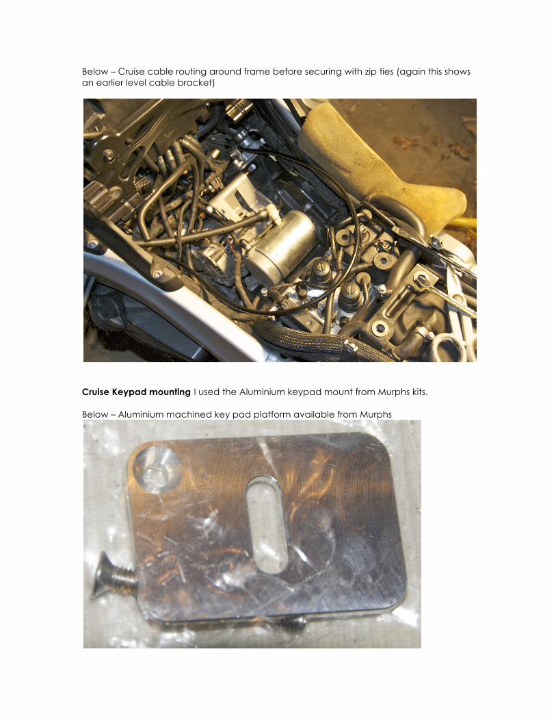
Below – Cruise cable routing around frame before securing with zip ties (again this shows an earlier level cable bracket)
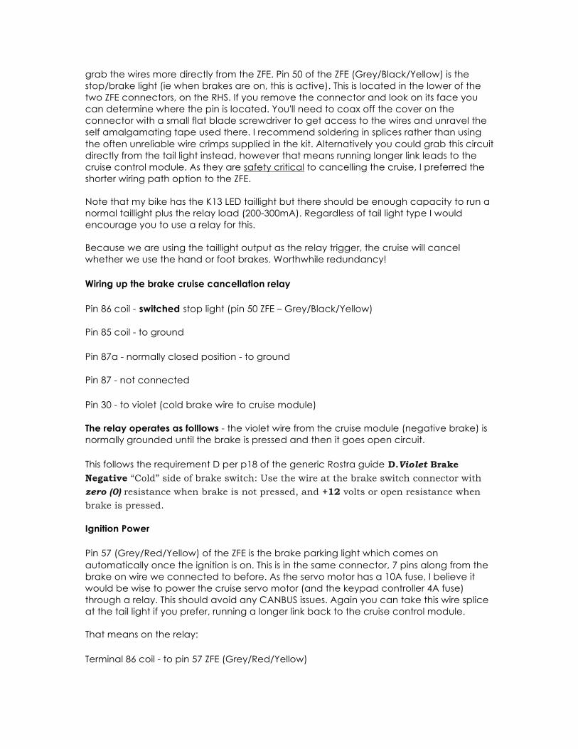
Cruise Keypad mounting I used the Aluminium keypad mount from Murphs kits.
Below – Aluminium machined key pad platform available from Murphs

As is, this platform will not bolt up to the clutch bar bolts as the boss on the bottom is a few millimetres too wide. Ergonomically it would have looked a little odd there anyway being a little too horizontal. So, I made up a small bracket to tilt the platform towards the rider. Alternatively, you could stick the keypad to the steering yoke otherwise.
Below – small black bracket off the rear clutch master cylinder mounting bolt I made to mount the keypad mount and angle towards the rider
Below – with keypad controller mounted. Looks almost original BMW

ELECTRICAL INSTALLATION
It is never a good idea to expect circuits to provide several extra amps of current that they were never designed for. Too often this leads to the 'smoke getting let out' problem…so, in this implementation we rely on nothing except battery power, two relays and a clutch banjo switch to do the work for us. I was less than impressed with the way Rostra suggested to obtain power and I do not recommend their method.
The K1200S runs a 42A alternator and has plenty of headroom to support such an accessory as a cruise control module. Check your bike’s electrical specifications to ensure that your alternator is of sufficient capacity to support around an extra ~150W load. Cruising then conking out because you’ve drained all your electrical resources is not cool.
The relays required are convenient to mount near the cruise module. (In the picture on my bike I have removed the front 2/3 of the LHS snorkel allowing access to the attachment points on the subframe. I like the induction noise without one snorkel– rather Subaru WRX like). Otherwise find another location nearby.
Below – relay mounting in LHS snorkel area. Note silver box is a HID ballast. Shown without airfilter and without rear 1/3 of snorkel fitted
Brake switch cruise cancellation wiring considerations Note - both brake switches are wired direct into the ZFE (central electronics module). However BMW's circuitry is such that the switches themselves will NOT have enough current to drive a relay. They are logic level only. Because of this, we will use the taillight output to trigger a relay instead. This is convenient for most bikes I expect and easy to find the wires too.
Since we are mounting the cruise module atop the ZFE though, on the K1200S we can
grab the wires more directly from the ZFE. Pin 50 of the ZFE (Grey/Black/Yellow) is the stop/brake light (ie when brakes are on, this is active). This is located in the lower of the two ZFE connectors, on the RHS. If you remove the connector and look on its face you can determine where the pin is located. You'll need to coax off the cover on the connector with a small flat blade screwdriver to get access to the wires and unravel the self amalgamating tape used there. I recommend soldering in splices rather than using the often unreliable wire crimps supplied in the kit. Alternatively you could grab this circuit directly from the tail light instead, however that means running longer link leads to the cruise control module. As they are safety critical to cancelling the cruise, I preferred the shorter wiring path option to the ZFE.
Note that my bike has the K13 LED taillight but there should be enough capacity to run a normal taillight plus the relay load (200-300mA). Regardless of tail light type I would encourage you to use a relay for this.
Because we are using the taillight output as the relay trigger, the cruise will cancel whether we use the hand or foot brakes. Worthwhile redundancy!
Wiring up the brake cruise cancellation relay
Pin 86 coil - switched stop light (pin 50 ZFE – Grey/Black/Yellow)
Pin 85 coil - to ground
Pin 87a - normally closed position - to ground
Pin 87 - not connected
Pin 30 - to violet (cold brake wire to cruise module)
The relay operates as folllows - the violet wire from the cruise module (negative brake) is normally grounded until the brake is pressed and then it goes open circuit.
This follows the requirement D per p18 of the generic Rostra guide D.Violet Brake Negative “Cold” side of brake switch: Use the wire at the brake switch connector with zero (0) resistance when brake is not pressed, and +12 volts or open resistance when
brake is pressed.
Ignition Power
Pin 57 (Grey/Red/Yellow) of the ZFE is the brake parking light which comes on automatically once the ignition is on. This is in the same connector, 7 pins along from the brake on wire we connected to before. As the servo motor has a 10A fuse, I believe it would be wise to power the cruise servo motor (and the keypad controller 4A fuse) through a relay. This should avoid any CANBUS issues. Again you can take this wire splice at the tail light if you prefer, running a longer link back to the cruise control module.
That means on the relay:
Terminal 86 coil - to pin 57 ZFE (Grey/Red/Yellow)

Terminal 85 to ground
Terminal 87a - not connected
Terminal 87 - to battery
Terminal 30 - to 10A fuse and 4A fuse
Ignition relay operation summary - once ignition is switched on the brake parking light fires the relay to power the servo motor power (through 10A fuse) and cruise switch (through 4A fuse) direct from battery power.
Clutch Banjo switch to cancel cruise control
I recommend replacing the standard banjo bolt with a banjo switch (purchased separately, eBay or elsewhere). When the clutch is engaged the switch closes. If we ground the Neutral Safety Switch wire on the cruise module (light green colour) this provides a secondary form of cruise cancellation. As I value my life, I wired this in and strongly recommend you do likewise.
In order to fit this you will need to purchase an aftermarket M10x1.0 banjo bolt switch. A couple of cautions are worth noting here. Firstly the thread pitch varies: most Euro bikes are M10x1.0, but the Japanese bikes are M10x1.25. Secondly at least on the BMW, the banjo bolt was longer than the OEM banjo bolt and needed cutting down to length. In doing this you will need to drain the clutch reservoir – note that to get the lid off you have to compress the side tangs below the lid and also note that many BMWs use MINERAL oil called Vitamol V10, (not brake fluid), although Castrol sells a Mineral Oil Plus which will work fine and is cheaper. You can even use a 10wt fork oil apparently. You may need to purchase the small bleed valve/vent screw (part 32727695221) on the clutch slave cylinder, sold through BMW dealers. (Mine just had a grub screw there originally). The cap for the vent screw is part 32727695222.
Nice simple electrical connections here:
Red wire of clutch switch – to lime green wire of cruise module (Neutral Start Switch wire) Black wire of clutch switch – to ground.
Clutch switch operation summary – when the clutch lever is activated, the NSS wire is grounded. This cancels the cruise control activation as per the requirement G below from the Rostra guide:
G.Light Green Neutral Safety (NSS) The NSS function is a safety feature of the GlobalCruise. If a vehicle with an automatic transmission is accidentally “knocked” into
neutral while the vehicle is in motion and the GlobalCruise is active, the NSS wire,
when connected, will disengage the GlobalCruise before engine over-rev. Connect this
wire to a ground active wire when neutral safety switch is engaged. If the NSS wire is not “hooked-up”, the cruise control will function; however the engine over-rev protection will be inactive
Vehicle Speed Sensor
Many bikes have a Vehicle Speed Sensor wire incorporated within the wiring harness. BMW does too, and let me tell you it took me over a year to work out if and how this actually works…originally I used the Rostra VSS kit off the front forks but this by comparison is more expensive, difficult to mount and has potentially some undesirable failure modes. Put that one down to experience…
There is an accessory connector with 3 pins at the front right side of the battery. It has a blanking plug in it. BMW sell an auxiliary harness which plugs into this connector and 3 fly leads which you can use for powering things like Autocom etc. Pin 2 of this connector is the VSS lead which is the Blue/Green wire at the bike harness side.
It will not work simply by connecting to this lead, however it is not much more difficult to make it work. You need to purchase a 300 ohm 1 watt resistor, and join it to the accessory power and the other end to pin 2. You can then connect pin 2 to the Rostra grey wire, which is the VSS signal. Please solder this in for reliability and insulate the joins well using heatshrink and electrical tape.
The pulse rate on this signal is approximately 4919 pulses per mile (PPM) based on my digital multimeter measurement.
Engage Light
The Rostra keypad has a central LED but that is only to indicate that the system has been turned on to standby. If you want to have a light to indicate that cruise control has been activated a 12V light needs to be installed.
Initially I thought this would be a waste of time – surely you would know when it was in cruise. However after my first test ride I quickly appreciated the fact that I needed a light to debug the system and hence went about installing one quick smart. If you also want to be sure the cruise cancelled seeing the engage light go off is good peace of mind.
I purchased a 12V instrument cluster LED (complete with biasing resistor) and soldered some wires to it once I worked out its correct polarity. The Rostra cruise module has an orange wire, which is grounded (not powered) when cruise is active. So I grabbed a 12V feed from my ignition relay output and then connected this to the positive cathode side of the LED. The ground side of the LED went to the orange cruise wire.

Below – Cruise engagement LED in LHDS fairing panel (and fuses for cruise)
Engage light operation summary – when the Rostra module engages cruise control, it will ground the orange wire, which is connected to the ground side of the LED. Ignition power from the Rostra relay provides the battery power to the other side of the LED allowing the LED to light.
Controller keypad Black and Grey wires These black and grey wires are the illumination of the keypad, black being ground, grey being power. This is essential to wire up if you want to see the keypad at night. I used the relay ignition power to provide this feed. Do not confuse this with the grey cruise module harness wire (which is the VSS signal).

Below – with black and grey keypad wires connected correctly the switches become illuminated. Note central LED only indicates cruise is in ‘standby’ mode
DIP SWITCH SETTINGS As the Rostra kit is a generic automotive cruise kit, it can be configured to suit many different kinds of vehicles. We need to set the DIP switches accordingly to suit a bike. Refer to the Rostra guide on how to set the DIP switches, they're under the rubber bung on the cruise control module.
A caution here – beyond the lousy descriptions Rostra provide for the various settings, note that the settings are NOT mutually exclusive – ie they interact with each other. This makes tuning a fair pain in the arse. All I can suggest is that you start with a setting near mine and if unsatisfied with this change only one factor at a time to gauge the result. Getting the PPM right is the most important step first.

Below – DIP switches on Rostra Cruise Module – Note DIP switch settings shown are not final settings. Down is OFF, Up is ON. Note the Test LED is on the LHS of the switches and is hard to see.
Gain – The biggest problem with most bike installs is too much gain. This is basically because you have car like power and bike light weight. Your throttle linkage is also a variable here, shorter lever arms increase gain. Given the Rostra module expects it’s trying to move a 1000-1800kg car, instead of a 215kg bike, start with EXTRA LOW gain. Switches 1-2: OFF OFF. I tried the LOW setting but it resulted in too much overshoot and undershoot to the target speed. Most large capacity bikes above 750cc will need to keep the gain on EXTRA LOW. The Vstrom and CBR XX forums seem to agree.
Pulses Per Mile (PPM)– in theory with our VSS at 4919 PPM we should set the PPM to the 6000 PPM setting. However after a number of trials I found much better behaviour of the cruise system on the 8000 PPM setting (less aggressive, less overshoot of the target speed and less variation in speed control). Going higher than this will affect your minimum allowable cruise engagement speed – I haven’t bothered trying as it works well enough on the 8000 PPM setting and has a minimum engage speed of around 60km/h or 40mph. Switches 3-6: ON ON OFF OFF.
Other bikes with VSS wires built in will need to check with their manufacturer re the PPM rate. The maximum PPM the Rostra module can digest is 38,600. Exceed this and you will need to purchase/install a pulse divider network to reduce the pulse count. Note this is why you can’t use the ABS tonewheel – too many PPMs (plus I didn’t want to hack into the ABS system).
For those with a control system penchant, the PPM is effectively the sampling frequency. By increasing the PPM, you are effectively increasing the sampling rate, and therefore reducing the error (PV-SP) in a PID control system, and hence reducing the gain. It would

seem to me best to run the highest PPM feasible as long as you can still engage the cruise at highway speeds. Sure it’s great having cruise at low speeds but often traffic around you makes it less useful in practice.
Engine/Setup Timer – This describes the amount of time it takes from pressing the cruise button to the cruise module initially taking up control. As the bike has a high power to weight ratio start with the 8 CYLINDER/LOW setting. Switches 7-9: OFF OFF OFF. I would avoid any HIGH or EXTRA HIGH settings period, unless you have already set the correct PPM and tried all the other less aggressive engine/setup timer settings already. Take care here as setting the wrong setting may cause ‘bucking bronco’ syndrome. I ended up on 6 Cylinder/LOW as a final setting.
The control system gurus would understand this as being integral and derivative gain. I believe this affects more than initial take up, it also affects the rate of acceleration during speed corrections also.
VSS Source –If you had a wire in your bike harness which was a digital pulsed signal you would select ON for square wave VSS.
Transmission – Set to Automatic. Switch 11: ON. We are using the Neutral Start Switch for backup cruise cancellation. You can cut off the Tach wire on the cruise harness if you wish, or ground it.
Control Switch – This defines which keypad controller you are using. If buying the Murph's kit the control pad is an open circuit type. Switch 12: OFF. The Rostra website has more information on this if you are unsure, or ask the person you purchase your switch from as to which type it is.
SELF DIAGNOSTIC TESTING PROCEDURE The Rostra guide on p20 describes the Self Diagnostic Testing Procedure you must do before riding the bike. Put the module into diagnostic test mode by pressing the ON button and the Accel button simultaneously. The Test LED is adjacent to the DIP switches on the LHS, red in colour. Once the installation is complete you must pass these tests before trying it on the road.
1) Check the hand and foot brakes each light the test LED 2) Check that when you press the Set button it lights the test LED 3) Check that when you press the Accel/Resume button, it lights the test LED 4) There is a test to spin the wheel to check the VSS registers on the test LED. I
originally did this test with the Rostra VSS kit/magnets but after changing to the digital VSS solution in the wiring harness I did not repeat this test. I am unsure if you can spin either front or rear wheels independently and get the VSS to register. Rostra’s guide doesn’t really talk about verifying a digital VSS method to my knowledge. If you wired it up correctly it should work. No pulse received at the Rostra cruise module will certainly mean no cruise functionality.
Also check your clutch banjo switch works and shorts when the clutch is depressed, grounding out the orange cruise module wire.
Ensure you rectify any issues, where found. Turn the ignition off to reset the system.

When going for the test ride, familiarize yourself where the buttons are and what to do should the unexpected occur – foot, or hand brake, or clutch will deactivate the cruise, as will the OFF button on the keypad. Worst case, use the kill switch to kill the engine. Pick a quiet road, don’t try it out in peak hour OK? Keep speeds down. Use common sense.
TUNING
Having established that the system works, you can now try optimizing the various DIP switch settings to your application and preference if needed. Change one parameter at a time to gauge effectiveness and move in small steps. What is already listed earlier is how mine is set.
Note the behaviour of the system does vary with speed to some degree. You really need to try a variety of conditions before judging the overall performance of the settings under trial – lower and higher speeds, gentle undulations and larger undulations.
Overall I would compromise the system for slight undershoot up larger hills, minimal overshoot and smoothness of take up initially once engaged. Flat boring freeways is where you want this to work predominately.
BUTTONING UP AND WATERPROOFING
The keypad controller and cruise module may benefit from some neutral cure Silicon application to help keep water out. Note that the controller I have used is expected to be installed inside a car.
Below – Siliconing up the DIP switch cover and wire outputs from the cruise module with neutral cure silicon

Below – silconing up the controller pad – centre wires to be siliconed up also before removing the 3M tape backing and sticking it to the aluminium support bracket.
TRIPLE CHECKS TO ENSURE YOUR SAFETY The main areas you need to triple check to ensure your safety are:
1) The Throttle Linkage – activate the throttle by hand and satisfy yourself that the cruise cable does not catch on anything. If it does, the throttle will hang open, which could be fatal. Try different scenarios, slow and rapid throttle opening, full and part throttle. In the position shown it should backfeed into its sheath.
2) Self Checks in Diagnostic mode – ensure you complete and pass all the checks before road testing. No compromises!
3) Road test on a quiet road away from traffic. Keep speeds low and cover the switches. Wear all your safety gear – helmet, gloves, leathers and boots.
Good luck with the installation – remember your safety must not be compromised. Install this kit like your life depended on it, because it does! Inspect the system regularly and hopefully you'll enjoy an electronic cruise for years of great motorcycling.
Finally – check with your insurer before fitting this kit. Initial discussions with a learned motorcycle industry insider suggested that an engineer’s certificate would probably be needed to be insurable. Shop around also as you may find some insurers are more understanding about this kind of accessory than others.
Cheers Kendrick (kpavey on the BMW Superbikes forum)