rotalign ultra shaft handbook
DESCRIPTION
Manual de operación del sistema de alineamiento de maquinaria Rotalign Ultra Shaft.TRANSCRIPT

ROTALIGN® UltraOperating handbook - Shaft alignment

Foreword
1
A user’s handbook
Dear Customer,
Welcome to the world of laser-optical shaft alignment using ROTALIGN Ultra, another
innovative product from PRÜFTECHNIK, the inventors of laser shaft alignment.
This handbook sets out to help the instrument user work through the instrument with
the required ease. It is the standard work for both ROTALIGN Ultra “Advanced” and
“Lite” versions, and meant to be a quick learning tool that hopefully should make
compelling reading.
PRÜFTECHNIK Alignment Systems GmbH
Freisinger Str. 34
85737 Ismaning
Germany
Tel +49.89.99616-0
Fax +49.89.99616-100
Email [email protected]
Edition July 2011
Part number ALI 9.855.G
Firmware version 2.1x
ROTALIGN® is a registered trademark of PRÜFTECHNIK Dieter Busch AG. PRÜFTECHNIK
products are the subject of patents granted and pending throughout the world.
Contents subject to change without further notice, particularly in the interest of
further technical development. Reproduction, in any form whatsoever, only upon
express written consent of PRÜFTECHNIK Alignment Systems GmbH.
© Copyright 2011 by PRÜFTECHNIK Alignment Systems GmbH

ROTALIGN Ultra Shaft handbook
2
Foreword
ROTALIGN Ultra is a user-friendly measurement system, thanks to its intuitive
operation, ergonomic design and its many beneficial features. The result of continued
development, the system has a new 5.7-inch colour TFT sunlight readable full VGA
screen and a faster processor. It also features an alphanumeric keyboard with stra-
tegically placed navigation keys that handles all data entry functions, a long lasting
rechargeable battery, handy on-screen context menu, a remarkable file storage
capacity and computer LEDs that give the instant status of the alignment condition
and laser beam adjustment.
The system is extremely customizable, has a comprehensive set of features and
straightforward operation. The features are based on a tier system resulting in the
versions “Lite” and “Advanced”. The difference between the two versions is a slight
adjustment in feature level. This difference is easily overcome by upgrading from
“Lite” to “Advanced”. This handbook uses the “Lite” and “Advanced” icons to dif-
ferentiate between features available in the two versions. As most of the description
in the handbook is based on the “Lite” version, the “Advanced” icon will be used to
highlight features not available in the “Lite” version.
ROTALIGN Ultra “Advanced” handles the alignment of drive trains comprising up to
14 machines, while the “Lite” version is used for machine trains of up to 6 machines.
The ‘Dimensions’ screen is so structured that machine and coupling properties can
be entered directly. ROTALIGN Ultra “Advanced” incorporates standard deviation,
a function that evaluates the reliability of the measurement results. The quality of
the measurement may be evaluated using the measurement ellipse which shows the
points measured and the angle of rotation.
The system is delivered together with ALIGNMENT REPORTER, a PRÜFTECHNIK
Alignment Systems freeware used for generating and printing measurement reports,
as well as creating backup files.
If you have any suggestions for improvement or corrections (not just to this manual,
but also for hardware), please drop us a line. We would be glad to make improve-
ments wherever possible.
We look forward to hearing from you.
PRÜFTECHNIK Alignment Systems
Ismaning, Germany
LITE ADVANCED
ADVANCED
ADVANCED

Contents
3
ContentsA user’s handbook ............................................................................................................... 1
Foreword . . . . . . . . . . . . . . . . . . . . . . . . . . . . . . . . . . . . . . . . . . . . . . . . . . . . . . . . . . . . . . 2
Chapter 1: ROTALIGN Ultra package . . . . . . . . . . . . . . . . . . . . . . . . . . . . . . . . . . . . . . . . 5
ROTALIGN Ultra Lite Shaft package ALI 4.000/2-L ................................................................. 5
ROTALIGN Ultra Shaft package ALI 4.000/2 ........................................................................... 9
Safety notes ....................................................................................................................... 11
Getting to know the ROTALIGN Ultra computer ................................................................. 12
Laser and sensor ................................................................................................................ 15
Chapter 2: Using ROTALIGN Ultra . . . . . . . . . . . . . . . . . . . . . . . . . . . . . . . . . . . . . . . . . 21
Available applications and options ..................................................................................... 21
ROTALIGN Ultra configuration ............................................................................................ 22
Tips and tricks .................................................................................................................... 34
Creating templates ............................................................................................................. 36
Deleting created templates from the program manager ...................................................... 39
Chapter 3: Shaft alignment application . . . . . . . . . . . . . . . . . . . . . . . . . . . . . . . . . . . . 41
Starting the shaft alignment application ............................................................................. 41
Horizontal machine alignment - preparation ...................................................................... 43
1. Preparing for the alignment procedure ........................................................................... 43
2. Check soft foot .............................................................................................................. 44
3. Mount the brackets ....................................................................................................... 44
4. Mount laser and sensor .................................................................................................. 45
5. Connect the sensor ........................................................................................................ 46
6. Switch ROTALIGN Ultra on and start application ............................................................. 47
7.1 Enter machine dimensions ............................................................................................ 48
7.2 Machine properties ...................................................................................................... 51
7.3 Coupling properties ..................................................................................................... 55
8. Laser beam adjustment .................................................................................................. 60
9a. Taking measurements .................................................................................................... 62
9b. Taking measurements using the optional RF module .................................................... 64
10. Results ......................................................................................................................... 68
11. Align machine .............................................................................................................. 71
12. Saving and printing measurement files .......................................................................... 79
13. Alignment completion ................................................................................................. 86
Upgrading from Lite Shaft to Advanced version .................................................................. 86

ROTALIGN Ultra Shaft handbook
4
Chapter 4: Special alignment options . . . . . . . . . . . . . . . . . . . . . . . . . . . . . . . . . . . . . . 89
4.1 Measurement modes .................................................................................................... 89
4.2 Measurement options .................................................................................................. 97
4.3 Set-up options ............................................................................................................ 111
4.5 Soft foot .................................................................................................................... 125
Chapter 5: Updating ROTALIGN Ultra firmware . . . . . . . . . . . . . . . . . . . . . . . . . . . . . 133
Updating ROTALIGN® Ultra to version 2.0x ........................................................................ 133
Chapter 6: Special applications . . . . . . . . . . . . . . . . . . . . . . . . . . . . . . . . . . . . . . . . . . 139
6.1 Machine train alignment ............................................................................................ 139
6.2 Cardan shaft alignment .............................................................................................. 144
6.3 Flanged machines ...................................................................................................... 151
6.4 Flange-mounted horizontal machines .......................................................................... 163
Appendix . . . . . . . . . . . . . . . . . . . . . . . . . . . . . . . . . . . . . . . . . . . . . . . . . . . . . . . . . . . . 169
Suggested shaft alignment tolerances ............................................................................... 169
ROTALIGN Ultra technical data .......................................................................................... 171
Index . . . . . . . . . . . . . . . . . . . . . . . . . . . . . . . . . . . . . . . . . . . . . . . . . . . . . . . . . . . . . . . . 173

Introducing ROTALIGN Ultra Shaft
5
Chapter 1: ROTALIGN Ultra package
The hardware components for both ROTALIGN Ultra Advanced and ROTALIGN Ultra
Lite remain identical.
To upgrade from ROTALIGN Ultra Lite to ROTALIGN Ultra Advanced, simply
purchase the firmware registration certificate ALI 4.741.
ROTALIGN Ultra Lite Shaft package ALI 4.000/2-L
ALI 4.800 ROTALIGN Ultra case
ALI 4.202 ROTALIGN Ultra computer including:
ROTALIGN Ultra rechargeable battery
ALI 4.603
ROTALIGN Ultra stand ALI 4.201
ALI 3.610 Laser emitter including dust cap ALI 3.607
ALI 3.600 Sensor including dust cap ALI 3.606
�Note
To upgrade from ROTALIGN Ultra Lite to ROTALIGN Ultra Advanced, simply
purchase the firmware registration certificate ALI 4.741.
ALI 4.800 ALI 4.202 ALI 3.610 ALI 3.600

ROTALIGN Ultra Shaft handbook
6
ALI 3.581-2 Sensor cable
ALI 3.608 Adjustment tube
ALI 12.502-2 PC/USB cable
ALI 12.503 USB/peripheral devices cable
ALI 12.651.I AC power supply/charger
(region-dependent)
ALI 3.581-2 ALI 3.608 ALI 12.503
ALI 12.502-2 ALI 12.651.I

Introducing ROTALIGN Ultra Shaft
7
ALI 2.113 SET Compact chain-type bracket set
includes: ALI 2.114, ALI 2.115, ALI 2.170, ALI
2.171, ALI 2.172, ALI 2.173 and ALI 2.174
ALI 2.905 Lens cleaning cloth
ALI 3.588 Tape measure mm/inch
ALI 9.844.G ROTALIGN Ultra Shaft pocket guide
ALI 9.855.G ROTALIGN Ultra Shaft
operating instructions
ALI 2.113 SET
ALI 2.905
ALI 3.588ALI 9.855.G
ALI 9.844.G

ROTALIGN Ultra Shaft handbook
8
DOC 4.900.de/en ROTALIGN Ultra product catalog
ALI 9.638.G Shims mailing insert
ALI 13.701 CD ALIGNMENT REPORTER CD
ALI 13.700 CDS ALIGNMENT CENTER CD/Resources CD
ALI 13.700 CDSALI 9.638.GDOC 4.900.de/en
ALI 13.701 CD

Introducing ROTALIGN Ultra Shaft
9
ALI 4.741-L Shaft Alignment Lite firmware
registration certificate (not shown)
ALI 4.451 USB memory stick
0 0739 1055 Allen key (2.5 mm)
ROTALIGN Ultra Shaft package ALI 4.000/2
The items included in this package are identical to those of the ROTALIGN Ultra Lite
Shaft package ALI 4.000/2-L except for the firmware certificate. This package is
delivered with the Shaft Alignment firmware certificate ALI 4.741.
ALI 4.451 0 0739 1055

ROTALIGN Ultra Shaft handbook
10
Optional ROTALIGN Ultra components
ALI 4.620 SET Wireless data transmission module
package
ALI 4.605 ROTALIGN Ultra disposable battery
housing
ALI 4.615 Desktop charging station for ROTALIGN
Ultra rechargeable battery
ALI 4.410 Dust cap for computer sensor socket
ALI 4.620 SET
ALI 4.615ALI 4.605
ALI 4.410

Introducing ROTALIGN Ultra
11
Safety notes
ROTALIGN Ultra is to be used in industrial environments only for alignment of turbine
components, shafts, bores, measurement of straightness and flatness of different
surfaces. Although shockproof to the IP 65 standard, care must be taken to ensure
that the instrument is not subjected to mechanical knocks. ROTALIGN Ultra must
be operated only by properly trained personnel. No liability will be assumed when
components or operating procedures as described in this manual are altered without
permission of the manufacturer.
Symbols used in this handbook
The following symbols are used in this manual in order to draw the reader’s attention
to especially important text, such as that regarding possible sources of danger or
useful operating tips.
This symbol denotes general information and tips regarding operation of
ROTALIGN Ultra.
This symbol denotes information which must be followed in order to avoid
damage to equipment.
This symbol denotes information which must be followed in order to avoid
personal injury.
Numbers in red circles indicate the corresponding operating step described in
these instructions and must be performed exactly.
CE compliance and EMC
ROTALIGN Ultra fulfills the EC Guidelines for electric devices (73/23/EWG) and elec-
tromagnetic compatibility (EMC) (89/336/EWG). ROTALIGN Ultra has been tested to
the scope of:
› EN 61326 Edition 2004-05 › EN 61000-4-2 Edition 2001-12
› EN 61000-4-3 Edition 2003-11 › EN 61000-4-4 Edition 2002-07
› EN 61000-4-5 Edition 2001-12 › EN 61000-4-6 Edition 2001-12
› EN 61000-4-11 Edition 2001-12 › EN 55022 Edition 2003-09
Laser safety
The ROTALIGN Ultra system uses a class II laser beam. Class II lasers comply with the
requirements outlined in the USA’s FDA specification 21 CFR Ch. 1, Parts 1040.10 and
1040.11 as well as the ANSI standard. It also fulfills British standard BS 4803 (Part 1 to
Part 3) and European Industrial Standard IEC825.
This symbol denotes general information and tips regarding operation of
ROTALIGN Ultra.
This symbol denotes information which must be followed in order to avoid
damage to equipment.
This symbol denotes information which must be followed in order to avoid
personal injury.
Numbers in red circles indicate the corresponding operating step described in
these instructions and must be performed exactly.
�Note
�CAUTION
�WARNING
1

ROTALIGN Ultra Shaft handbook
12
The class II laser operates at a wavelength of 675 nm, with a maximum pulse duration
of 128μs, maximum radiant power of 0.8mW and maximum radiant energy per pulse
of 0.1μJ. No maintenance is necessary to keep this product in compliance with the
specifications referred to.
� Do not look directly into the laser beam at any time. (Since FDA specifica-
tions allow maximum exposure of 0.25 seconds, the natural blink reaction
of the human eye is normally sufficient to avert any danger, provided that
no optical instruments other than ordinary eye glasses/contact lenses are
used. But as natural blink reaction may fail to occur, care should be taken to
avoid staring into the beam.)
� Do not insert any optical devices into the beam path.
� The red LED on the front of the laser illuminates whenever the laser beam
is emitted.
Getting to know the ROTALIGN Ultra computer
The ROTALIGN Ultra computer has been developed to effectively handle both simple
and complex shaft, bore and turbine diaphragm applications. The computer is also
used to carry out straightness and flatness measurements. ROTALIGN Ultra has a
customer-oriented user interface. It uses easy-to-follow icons and comprehensive
on-screen menus and hint texts, that enable even first-time users to operate the
computer without difficulty.
ROTALIGN Ultra is built to rugged industrial standards of shock and water resistance. It
contains a complete computer with a 5.7 inch color TFT full VGA display, oval-shaped
function and data entry keys, 4-way navigation keys, an On/Off/Enter key, an up key,
a clear key and a menu key.
Operating keys
�WARNING
� Do not look directly into the laser beam at any time. (Since FDA specifica-
tions allow maximum exposure of 0.25 seconds, the natural blink reaction
of the human eye is normally sufficient to avert any danger, provided that
no optical instruments other than ordinary eye glasses/contact lenses are
used. But as natural blink reaction may fail to occur, care should be taken to
avoid staring into the beam.)
� Do not insert any optical devices into the beam path.
� The red LED on the front of the laser illuminates whenever the laser beam
is emitted.
Function keys
Return/Clear/Menu keys
Navigation keys
On/Off/Enter key
Data entry keys

Introducing ROTALIGN Ultra
13
� The navigation keys are used to navigate through the menu and display items.
The ‘Enter’ key in the center is used to access any selected item or confirm an
action.
� The ‘On/Off/Enter’ key is used to perform the dual function of switching on
ROTALIGN Ultra, and accessing any selected item. To switch on, press and hold
e, the ‘On/Off/Enter’ key, for approximately 5 seconds.
� The ‘Up’ key is used as a back/return key, taking user to previously selected
function, or to exit current screen.
� The ‘CLR’ (Clear) key is used to delete information entered inadvertently.
� The ‘Menu’ key is used to callup menu options related to the selected display
screen. Pressing it twice brings up the global menu.
� The data entry keys are used to enter relevant data.
ROTALIGN Ultra possesses 3 function keys.
� The ‘Dimension’ key is used to access machine set-up where machine
dimensions and properties are defined.
� The ‘Measurement’ key is used to access the measurement screen.
� The ‘Result’ key is used to call alignment results into the display.
Power supply
ROTALIGN Ultra is powered using a 7.2 V 6.0 Ah Lithium-ion rechargeable battery ALI
4.603, which is to be charged only using the battery charger ALI 12.651. This can be
done with the battery inside the computer. The computer may continue to be used if
the battery is charged inside it.
Alternatively, use 6 standard ‘C’ size batteries contained in the optional battery
compartment ALI 4.605.
If the ROTALIGN Ultra computer is not in use for extended periods of time, a
month or more, the rechargeable battery or the standard batteries should be
removed from the unit. �CAUTION
If the ROTALIGN Ultra computer is not in use for extended periods of time, a
month or more, the rechargeable battery or the standard batteries should be
removed from the unit.

ROTALIGN Ultra Shaft handbook
14
ROTALIGN Ultra top panel connectors
Sensor / RS232 socket
Ensure correct ROTALIGN
sensor cable plug
orientation to avoid
damaging pins
USB host/slave port
The red dot on the USB
cable plug must match the
red dot on the USB port
Charger socket
The red dot on the charger
plug must match the red
dot on the battery socket
Connecting the battery
charger to ROTALIGN
Ultra – The LED next to
the battery symbol on the
keypad lights up when
charging takes place with
the system turned on
Battery compartment
ALI 4.605
If you are using the
standard ‘C’ size batteries,
it is recommended to
replace all of them at once.
Note the battery polarity
when inserting them in the
compartment ALI 4.605.
The battery compartment
is removed and replaced
in the same manner as the
rechargeable battery ALI
4.603
6 ‘C’ size batteries
Lift compartment or
rechargeable battery after
undoing the screws
Replace compartment or
rechargeable battery by
sliding it into the groove
appropriately
1 32
1
2
3
Note that available cables
may be connected to the
corresponding numbered
sockets as follows:
ALI 3.581-2 / ALI
3.581-5 (sensor cable)
ALI 12.503 (short USB
cable), ALI 12.651 (charger)
ALI 12.502 (long USB
cable), ALI 12.503, ALI
12.651

Introducing ROTALIGN Ultra
15
Replacing batteries
The rechargeable battery ALI 4.603 and the battery compartment ALI 4.605 have
identical shapes and are therefore replaceable. If batteries require removal, turn over
the computer taking care not to damage the display and the hard keys. Undo the two
screws by turning them at least a quarter of a turn. With the screws loosened, lift
and pull the rechargeable battery or the battery compartment (depending on power
supply source) out. The reverse procedure is used to mount back the rechargeable
battery or the battery compartment.
Laser and sensor
Laser ALI 3.610
The semiconductor laser diode emits a ray of red light (wavelength 675nm) which is
visible where it strikes a surface. The beam is emitted with a diameter of approx. 5mm
(3/16”). Because the laser is operated in short pulses and not as a continuous beam,
its power is low enough to qualify for Class II safety rating.
Do not stare into the laser beam!
The beam is adjusted during set-up by changing its vertical and horizontal angles with
thumbwheels so that the beam strikes the sensor lens straight on.
The laser is water and dust resistant. The internal optics and electronics are internally
sealed, preventing possible contamination, e.g. via the two thumbwheel slots.
The battery compartment is not watertight. If water enters this compartment,
open it and dry it out. The battery should then be replaced.
Laser battery
The laser is powered by a single 9 V battery (type IEC6LR61) which, depending on
battery make and operating patterns, provides a typical operating duration of 80
hours. A lithium battery of this size can also be used, increasing operation up to 150
hours. NiCad rechargeables may also be used.
As the battery becomes depleted, the color of the ‘laser active’ indicator LED
changes from red to yellow. When this occurs, the battery should be replaced.
The battery is replaced by removing both screws from the battery compartment cover
of the laser housing.
Do not stare into the laser beam!
The battery compartment is not watertight. If water enters this compartment,
open it and dry it out. The battery should then be replaced.
As the battery becomes depleted, the color of the ‘laser active’ indicator LED
changes from red to yellow. When this occurs, the battery should be replaced.
�CAUTION
�CAUTION
�WARNING

ROTALIGN Ultra Shaft handbook
16
� Under no circumstances may the four smaller housing screws be removed,
as that would result in misadjustment and would void all warranty
coverage.
� Be aware that when NiCad rechargeable batteries are used as replacements,
their voltage tends to drop quite rapidly as they become depleted. This may
limit the effective warning time (see note above), so a fully-charged spare
should be held in reserve.
� Used batteries should be disposed of in an environmentally-sound manner!
Sensor ALI 3.600
The sensor contains two position detectors, which measure the exact position of the
laser beam as the shafts are rotated. The sensor also contains an electronic inclinom-
eter for shaft rotation measurements.
The sensor has two indicator LEDs on its front side, one green and the other red, to
indicate beam adjustment.
The sensor is powered by the ROTALIGN Ultra computer via a cable (ALI 3.581-2)
through which measurement data also pass.
If using wireless data transmission, the sensor is powered through the optional
RF module which is also used to pass measurement to the sensor.
Cable connection
Insert the angled plug into the sensor socket as shown; note the keyway indicating
proper plug orientation. Screw down the cable fitting to tighten the connection. The
angled plug should be left permanently connected to the sensor, even when storing
the system in its case, as this will help avoid damage to cable pins, plugs and sockets.
Never turn the plug itself, as that can damage the cable pins!
Note correct plug orientation indicated by the markings on the plug and the
socket.
Service and care
The calibration accuracy of the system should be checked every two years as
indicated by the date wheel label (shown at right) located on the back of the
sensor housing.
Please return the system to your authorized PRÜFTECHNIK service centre for
calibration checking by the date indicated.
� Under no circumstances may the four smaller housing screws be removed,
as that would result in misadjustment and would void all warranty
coverage.
� Be aware that when NiCad rechargeable batteries are used as replacements,
their voltage tends to drop quite rapidly as they become depleted. This may
limit the effective warning time (see note above), so a fully-charged spare
should be held in reserve.
� Used batteries should be disposed of in an environmentally-sound manner!
If using wireless data transmission, the sensor is powered through the optional
RF module which is also used to pass measurement to the sensor. �Note
The optional RF module is
described in chapter 3.
�CAUTION
Never turn the plug itself, as that can damage the cable pins!
Note correct plug orientation indicated by the markings on the plug and the
socket.
�Note
The calibration accuracy of the system should be checked every two years as
indicated by the date wheel label (shown at right) located on the back of the
sensor housing.
Please return the system to your authorized PRÜFTECHNIK service centre for
calibration checking by the date indicated.12
Month
Year

Introducing ROTALIGN Ultra
17
Scratch-resistant lens
Rubber housing
Cable socket
Locking knob
CAUTION
PRÜFTECHNIK
AG
D- 857
37 IS
MANIN
G
Compl
ies with
21 CFR
104
0.10
and
21 C
FR 104
0.11
Ope
ning
hou
sing
cau
ses m
is-
adju
stm
ent a
nd voi
ds w
arra
nty
S/No
Type
Date
of m
anifa
ctur
e
DURACELL
ALKALINE
DU
RA
CE
LL
AL
KA
LIN
E
MN
1604 6
LR
61 9
,0V
Under no circumstances
may the four smaller
housing screws be removed,
as that would result in
misadjustment and would
void all warranty coverage.
Laser complies with
21 CFR 1040.10 and
21 CFR 1040.11
Replacing laser battery“Beam active” indicator LED
Vertical beam position
adjustment thumbwheel
Rubber housing
Battery compartment
Horizontal beam position
thumbwheel
Locking knobOn/Off toggle switch
Sensor
ALI 3.600
Laser ALI 3.610

ROTALIGN Ultra Shaft handbook
18
The laser beam is at the
edge of the the position
detector and both the red
and green LEDs are blinking
fast
The amber computer LED is
on and steady
The red computer LED is on
and steady
The laser beam is out of the
position detector range and
the red LED is on and steady
red LED
green LED

Introducing ROTALIGN Ultra
19
Any waste electrical and electronic parts of the ROTALIGN Ultra system including
memory sticks must be disposed off in accordance with the WEEE ( Waste
Electrical and Electronic Equipment) Directive. Such parts must be taken to the
nearest collection facility.
Any waste electrical and electronic parts of the ROTALIGN Ultra system including
memory sticks must be disposed off in accordance with the WEEE ( Waste
Electrical and Electronic Equipment) Directive. Such parts must be taken to the
nearest collection facility.
The laser beam lies at the
center of the position
detector measurement
range. The red LED is off
while the green one blinks
slowly
The laser beam lies in
the position detector
measurement range. The
red LED is off while the
green one blinks slowly
The green computer LED is
on and steady
The blue computer LED is
on and steady

ROTALIGN Ultra Shaft handbook
20
This page intentionally left blank

Configuration
21
Chapter 2: Using ROTALIGN Ultra
Press e to switch on the computer
Press and hold e the ‘On/Off/Enter’ key for about 5 seconds. The opening screen
below appears.
Use the navigation keys to access available applications and options. The navigation
direction is either upwards/downwards or sideways.
Available applications and options
The following applications and options can be selected via the program manager start
screen.
i) Resume – Depending on the set customization option, the resume option loads a
default template or the most recent job.
ii) Shaft alignment – used to position the centerlines of rotation of two (or more)
machinery shafts in line with each other.
iii) Straightness – used to measure straightness.
iv) Flatness – used to determine levelness and flatness of surfaces.
v) BORALIGN –used for bore and turbine alignment.
vi) Right angle check – used to measure perpendicularity.
vii) Tolerance editor – used to define individual alignment tolerace levels in terms of
any desired coupling alignment parameters such as offset and angularity.
ADVANCED

ROTALIGN Ultra Shaft handbook
22
viii) Soft foot – starts the soft foot wizard [the wizard is available in Advanced Shaft
only] which assists in correcting soft foot.
ix) Templates – used to select a specified template for a new measurement job.
x) Device configuration – used to configure the ROTALIGN Ultra computer settings.
When this option is selected, the following computer settings can be configured:
date and time, language, units, power management, printer set-up, device info,
display, owner info and users’ list. The option is also used to open the licence
manager, start the word completion function, customization, change users,
backup and restore files.
xi) Turn off – is used to turn ROTALIGN Ultra off.
Applications and options that have not been licenced will appear in program
manager grayed out.
ROTALIGN Ultra configuration
From the ‘Program Manager’ screen use the navigation keys to highlight
‘Configuration’.
ADVANCED
�Note
Applications and options that have not been licenced will appear in program
manager grayed out.

Configuration
23
Press e to reveal the items used to configure the ROTALIGN Ultra computer.
Setting date and time
Accessing this section allows you to set the current date and time, choose the proper
time zone, and change the date and time presentation formats.
Use the navigation keys to
select item to be changed.
To change digit values press
e followed by f to
increase value or g to
decrease value.
A drop down menu is
available for the selection of
time zones.

ROTALIGN Ultra Shaft handbook
24
To change the presentation format, press q. The context menu appears.
Use f/g to highlight ‘Format’ and press e to confirm selection. The ‘Date
& time format’ screen appears.
Alternatively, access
‘Format’ by pressing 3.
Use the navigation keys to
move from one dropdown
menu to the next. When
a dropdown menu box
is highlighted, press e
to display the available
formats. Use f/g
to highlight the desired
format, confirming selection
by pressing either e or
ß.

Configuration
25
Language selection
Accessing this section allows you to select preferred country language.
Use f/g to highlight preferred language. Press e to confirm selection.
Setting units
Accessing this section allows you to change the units and resolution of physical
quantities used in ROTALIGN Ultra. In this case, resolution is defined as the
measurement precision in two or three decimal places
Use the navigation keys to
move from one dropdown
menu to the next. When
a dropdown menu box
is highlighted, press e
to display the available
options. Use f/g
to highlight the desired
option, confirming selection
by pressing either e or
ß.
The green checkmark
indicates the currently set
language.

ROTALIGN Ultra Shaft handbook
26
Different system units can be configured by pressing q while in the unit screen. The
context menu appears.
Power management
This section displays the current battery status, allows you to control the power
management features of shutdown, hibernate (sleep mode), and standby.
Use f/g to
highlight the preferred
system of units. Confirm
selection by pressing either
e or ß. Alternatively,
the system of units may be
selected by pressing the
corresponding data entry
key. Pressing 4 selects
the metric system.
To set standby and
hibernate modes, press
e. Highlight required
mode from the drop down
menu that appears using
f / g. Confirm
selection by pressing e
or ß.
In hibernate, power is cut
off completely while in
standby it is not cut off
completely.

Configuration
27
Printer set-up
Accessing this section allows you to set-up printers and the printing configuration on
ROTALIGN Ultra.
Use the navigation keys to scroll through the settings and print options. Press e to
select or edit an option or setting.
More printing options can be accessed by pressing q while in the print screen. The
context menu appears.
Select printer by pressing
e, and highlighting
required printer from the
drop down menu that
appears using f/g.
Selection is confirmed by
pressing any one of these
keys – e or ß or h
or i.
Scroll the context menu
using f/g. Press
e to confirm selection.
Alternatively access the
menu item directly by
pressing the corresponding
data entry key.
Pressing 5 accesses the
window where printing
preferences such as page
size, pages per sheet, page
orientation, paper source or
duplex printing may be set.

ROTALIGN Ultra Shaft handbook
28
Device info
Accessing this section allows you to see the current file space and operating memory
statistics, the CPU data, the ROTALIGN Ultra serial number, and information about the
core software used in the device.
‘Device information’ is accessed via the ‘Application information’ icon in the
‘Configuration’ screen. When the ‘About Program Manager’ screen appears, press
q. A context menu with the item ‘Device information’ appears.
Use f/g to highlight ‘Device information’. Press e to confirm selection and
display device information.
ROTALIGN Ultra serial
number

Configuration
29
Display brightness
Accessing this section allows you to change the brightness of the display screen.
The display brightness is adjusted using f (increases) or g (decreases).
Word completion
The word completion mechanism helps save keystrokes and time while typing. It also
helps you to make sure that the misspelling of words is avoided. When a user begins
the entry of a word already listed in the system dictionary, the word is completed
automatically, and may be adopted by pressing e.
The ‘Word completion’
screen displays choice of
words available for the
automatic completion
mechanism.

ROTALIGN Ultra Shaft handbook
30
To add, delete or test the completion mechanism, press q. A context menu as
shown below appears.
New additions can be made on the “User defined” column only. To do this, use
f/g to highlight ‘Add’. Press e to confirm selection. Use the data entry
keys to enter the new word in the dialog box that appears.
The new word is adopted within the user defined column by pressing either ß/e or
using the context menu item “Accept changes” (refer to screen on the next page).
Use f/g to
highlight action required
from the context menu
confirming selection by
pressing e.
When entering user defined
words that contain both
upper and lower case
characters, as well as
numerals, use o to cycle
through the three options.
Press and hold down o
while observing the status
indicator at the top right
corner of the dialog box.
This displays the character
to be entered.
When entering letters, 0
is used to enter a blank
space.

Configuration
31
To test if a word is available in the dictionary, use f/g to highlight ‘Test
dictionary’. Press e to confirm selection. Use the data entry keys to enter the first
letter of the word required. The word high up in alphabetical order will appear in the
dialog box. Test further by entering the second letter. If necessary enter the third and
fourth letters to confirm whether the word is available in the dictionary.
An additional editing facility is achieved using the dialog box menu bar items. The bar
appears by pressing q when the dialog box is open.
In the screen opposite,
entering ‘G’ as the first
letter reveals that the word
‘Gearbox’ exists in the
dictionary. If looking up
the word ‘Generator’, we
would be required to enter
the first three letters (‘gen’)
for results.
The additionaI menu bar
is navigated using the
navigation keys.

ROTALIGN Ultra Shaft handbook
32
Addition and deletion of words is possible only with user defined words.
Predefined words are not available for editing.
Customization
Customization makes it possible to change the device settings such that the
information displayed is suited to individual needs. These settings are carried out in the
‘Customization options’ screen which accessed by pressing e with ‘Customization’
highlighted.
Options available include:
Keyboard backlit
Two options are available – backlit is set either “off” or in “normal use”
Status bar hints
Four options are available – “normal use”, “never in menu”, “only in menu” and
“never”
Beep
The internal beeper can emit sound signals when specific tasks take place. The drop
down menu reveals the following options:
“Never” – beeper is permanently off
“System events only” – the sound signal is emitted only when a system event occurs
“Every key stroke” – the sound signal is emitted when a system event occurs and each
time a button is pressed
Workflow assistant
This option is used to provide hints to the user on how to proceed with using the
system. Options available include – “never”, “always”, and “only when important”
�Note
Addition and deletion of words is possible only with user defined words.
Predefined words are not available for editing.
Select item to be
customized by highlighting
the respective item box
using the navigation
keys. Press e and use
f/g to select
desired setting from the
drop down menu that
appears. Confirm setting by
pressing e/ß or any of
the navigation keys.

Configuration
33
Resume policy
This option is useful for the resume functionality of ROTALIGN Ultra. The drop down
menu reveals the following items:
“Resume files manually” – a new job is started by loading a default template
“Always resume last file” – the most recent job resumes automatically
Navigation scheme
Four options on how to navigate through the menu items are availabe – “Enter always
needed to edit”, “Quick editing with up/down”, “Editing moves focus” and “All
features listed above”
This customization option is very important in that it determines how a user
navigates through the system. It would be advisable to try out the different
options to establish which option suits you best. In this operating instruction
we will try to stay with the option “editing moves focus” and depending on the
situation, try and explain the option “all features listed below”.
Word completion
Two options are available – “enabled” or “disenabled”
Context menu items
Useful menu items that include accessing the program manager, turning the
computer off and configuring the instrument can be accessed via the context menu
that appears when q is pressed at any time. The item ‘Menu’ is used to access the
global menu.
This customization option is very important in that it determines how a user
navigates through the system. It would be advisable to try out the different
options to establish which option suits you best. In this operating instruction
we will try to stay with the option “editing moves focus” and depending on the
situation, try and explain the option “all features listed below”.
�Note
Context menu items
available from the program
manager screen.

ROTALIGN Ultra Shaft handbook
34
Tips and tricks Program manager
� While in the program manager, the data entry keys are used to select the
corresponding application icon in a numerically ascending order.
General
� Pressing q long enough opens the global menu.
� Pressing q twice opens the global menu. This is the quicker option.
� Pressing e for approximately 3 seconds prompts the ‘turn off system’ dialog.
Context menu items
available from the set-up
screen.
Global menu from the Shaft
application set-up screen.

Configuration
35
� Pressing e for approximately 7 seconds resets the system.
� Pressing either h or i long enough moves the view of the train to the left or
right respectively.
� Pressing the corresponding data entry key moves the view to the respective
coupling position (observe inset in display).
� Pressing either o or p moves the view of the train to the right or left
respectively.
The displayed view shows
machines A and B with
coupling 1
The displayed view shows
machines B and C with
coupling 2

ROTALIGN Ultra Shaft handbook
36
Dimensions (set-up)
� When in set-up and units are set to Imperial system, entering a dimension as
11.3.8 corresponds to 11 3/8 in.
� Pressing c while in set-up prompts the deletion of the selected machine.
� When selecting type of machine the orientation of the machine can be altered
by pressing either h or i.
� Pressing d twice while in set-up zooms the machine train out and in again.
� When entering data (file and element names), pressing o cycles through the
characters that can be entered, and pressing ‘1’ long enough enters the value .
� Press f to zoom out the image (any one of the train elements has to be
highlighted).
� Press g to zoom in the image (any one of the train elements has to be
highlighted).
Measurement
� Pressing m twice activates auto measurement.
In auto measurement any of the three measurement modes – continuous sweep,
multipoint or static measurement is started directly by the appropriate action.
� sweep mode is activated by rotating the shafts
� multipoint is started by pressing e � static measurement is started by pressing either the data etry keys or any of
the navigation keys
Results
� Pressing g and holding on, while in results, cycles the results between
vertical (V), horizontal (H) and both H&V.
Creating templatesA template is a file that serves as a pattern for alignment set-ups that are repeated
frequently. Their main purpose is to save you time by not having to reconfigure the
same set-up many times. As such, it can contain all known dimensions, target speci-
fications, thermal growth values, preferred measure mode, preferred machine icons
and coupling types.
Any readings already taken and present in the measurement table will be flushed.
Readings should only be saved in active job files and cannot be saved with a
template.
In auto measurement any of the three measurement modes – continuous sweep,
multipoint or static measurement is started directly by the appropriate action.
� sweep mode is activated by rotating the shafts
� multipoint is started by pressing e� static measurement is started by pressing either the data etry keys or any of
the navigation keys
�Note
ADVANCED
Any readings already taken and present in the measurement table will be flushed.
Readings should only be saved in active job files and cannot be saved with a
template.
�Note

Configuration
37
Start Shaft Alignment application and define template.
Press q twice to open the global menu.
Use the navigation keys to highlight ‘File’ / ‘Save as template’. Confirm selection by
pressing e.The “Save as template” window appears. Press e to edit the name of
the template in the editing box that opens.
ADVANCED

ROTALIGN Ultra Shaft handbook
38
Press e to confirm template name and save template
The new template will now appear on the templates list.

Configuration
39
Deleting created templates from the program manager
Press q twice to open the global menu while in the Shaft Alignment application.
Use the navigation keys to highlight ‘File’/’Delete’. Confirm by pressing e. The
‘Delete document’ window appears. Press q to open the context menu and use the
navigation keys to highlight ‘Template’/’Template’.
ADVANCED

ROTALIGN Ultra Shaft handbook
40
Confirm selection by pressing e. The ‘Delete template’ window opens with a
complete list of all available templates.
Use the navigation keys to highlight the template to be deleted. With the template
highlighted, press q. The context menu appears.
With the context menu displayed, press 9. A message pops up requesting confir-
mation if the file should actually be deleted. Use the navigation keys to highlight ‘Yes’
and confirm selection by pressing e. The template is deleted from the template
list.
Alternatively, use
f/g to highlight
‘Delete’, confirming
selection by pressing
e. The hint requesting
confirmation to delete
template then appears on
the display.
If you select a template
and set it as the ‘default’
template, a working file
based on this template
will be started every time
you launch the Shaft
Alignment application.
If you do not designate
a default template, a
working file based on the
factory default template
will launch instead.

41
Chapter 3: Shaft alignment application
Starting the shaft alignment application
Before the application can be started, a licence code must be entered in the
licence manager. In most cases the application is licenced at the factory and the
system is delivered with the Shaft Alignment firmware registration certificate ALI
4.741 which contains the entered licence code.
Starting the licence manager
After switching ROTALIGN Ultra on, use the navigation keys to highlight
‘Configuration’.
Press e to access this option.
Before the application can be started, a licence code must be entered in the
licence manager. In most cases the application is licenced at the factory and the
system is delivered with the Shaft Alignment firmware registration certificate ALI
4.741 which contains the entered licence code.
�Note

ROTALIGN Ultra Shaft handbook
42
Use the navigation keys to highlight ‘License Manager’. Press e to access ‘License
Manager’. Use f/g to highlight ‘Shaft Alignment’. Press e and proceed to
enter the application licence code (registration key) in the editing box.
After successful registration, a green tick appears next to the application and the
suffix ‘Lite’ if registering the Lite Shaft version. The application shaft alignment can
be started.
Please refer to page 86 for a brief description on upgrading from Lite Shaft to
Advanced Shaft version.
LITE
If registering the Advanced
version, the suffix
‘Advanced’ appears after
the version number.

43
Horizontal machine alignment - preparation
1. Preparing for the alignment procedure
Before using the ROTALIGN Ultra shaft alignment application, prepare the machines
as described below.
Switch off the machines before commencing work, and make sure that they
cannot be started accidentally!
a. Solid, flat foundation
A solid, rigid foundation is required to obtain correct, lasting shaft alignment that
allows long-term uninterrupted machine service.
b. Machine mobility
If the machine to be moved stands directly on the foundations, it cannot be lowered
for alignment correction. It is therefore advisable to start with about 2 mm (80 mils)
of shims beneath the feet of both machines. Hydraulic or screw-type positioning aids
are recommended for horizontal movement.
c. Rigid couplings
Rigid couplings must be loosened before measurement so that they do not distort the
alignment condition.
d. Shaft play and coupling backlash
Axial shaft play of up to 3 mm (1/8”) has no adverse effect on alignment results (but
not necessarily for machine operation).
e. Soft foot
Soft foot causes the machine frame distortion every time the bolts are loosened or
tightened, making proper alignment difficult or impossible.
f. Thermal growth, alignment targets, tolerances
These values can be obtained from the individual machine specifications, and then
entered into the program. In addition, a built in thermal growth calculator can help
you derive these values from the observed changes in temperature.
g. Measurement separation
Since ROTALIGN Ultra requires no mechanical connections (such as cantilevered dial
indicator brackets) to span over the coupling during measurement, alignment may
easily be performed over large laser – sensor separations.
Note that over very large distances the shafts and coupling may sag, and the machines
may need to be aligned to take this into account. Refer to the machine manufacturer’s
specifications.
Switch off the machines before commencing work, and make sure that they
cannot be started accidentally! �WARNING
Horizontal shaft alignment

ROTALIGN Ultra Shaft handbook
44
2. Check soft foot
Refer to section on soft foot on page 125.
3. Mount the brackets Mount the brackets on either side of the coupling on either the shafts or on the solid
coupling hubs, and both at the same rotational position.
Please note the following in order to obtain the highest possible measurement
accuracy and to avoid damage to equipment:
� Ensure that the brackets fit solidly onto their mounting surfaces!
� Do not use self-constructed mounting brackets, or modify the original
bracket configuration supplied by PRÜFTECHNIK Alignment (for example,
do not use support posts longer than those supplied with the bracket).
Bracket mounting procedure
To fit the compact chain brackets, refer to the diagram shown below and follow the
instructions carefully.
1. Choose the shortest support posts which will still allow the laser beam to pass
over or through the coupling. Insert the support posts into the bracket.
2. Fasten them in place by tightening the hex screws on the sides of the bracket
frame.
3. Place the bracket on the shaft or coupling, wrap the chain around the shaft
and feed it through the other side of the bracket: if the shaft is smaller than the
width of the bracket frame, insert the chain from the inside of the bracket as
shown in the diagram; if the shaft is larger than the bracket width, insert the
chain into the frame from the outside.
4. Catch the chain loosely on the anchor peg.
5. Turn the bracket thumbscrew to tighten the assembly onto the shaft.
6. Clip the loose end of the chain back onto itself.
� Ensure that the brackets fit solidly onto their mounting surfaces!
� Do not use self-constructed mounting brackets, or modify the original
bracket configuration supplied by PRÜFTECHNIK Alignment (for example,
do not use support posts longer than those supplied with the bracket).
1
2
3 4
5
6
Anchor peg
�CAUTION

45
The bracket should now be tight upon the shaft. Do not push or pull on the bracket
to check, since this could loosen its mounting.
To remove the brackets, loosen the thumbscrew, then remove the chain from its
anchor peg.
The compact chain-type brackets cover most situations, but in cramped or
special cases, other types of brackets may be required. Ask your PRÜFTECHNIK
representative for details.
4. Mount laser and sensor Mount the laser on the support posts of the bracket fixed on the shaft of the left
machine (usually reference machine), and the sensor on the support posts of the
bracket fixed on the shaft of the right machine (usually moveable machine) – as
viewed from normal working position. Ensure that the yellow knobs are loosened
enough to let you slide the housing onto the support posts.
Clamp both the laser and the sensor onto the respective support posts by tightening
the yellow knobs. Ensure that the laser can pass over or through the coupling and is
not blocked. Fasten the sensor cable to one of the support posts using a cable clip.
Both the laser and sensor should be at the same height, as low as possible, yet just
high enough for the beam to clear the coupling flange. They should also visually
appear to be rotationally aligned to each other.
Make the final adjustments, loosening the brackets slightly if necessary, then rotating
them and retightening.
The compact chain-type brackets cover most situations, but in cramped or
special cases, other types of brackets may be required. Ask your PRÜFTECHNIK
representative for details.�
Note
Locking knob
Cable clip
Mount just high enough
to clear coupling
Laser
Sensor
Horizontal shaft alignment

ROTALIGN Ultra Shaft handbook
46
5. Connect the sensor
Insert the quick fit straight-ended sensor cable plug into the eight-pin socket on the
top of the computer housing with the red dot at the front.
Match the double-sided arrow head on the plug to the red marking on the
socket to ensure proper plug orientation; otherwise the pins inside the plug may
be damaged.
To disconnect, grasp the ribbed collar of the plug on the sensor cable
(ALI 3.581-2) and carefully pull it out of the ROTALIGN Ultra RS232/Sensor
socket.
Wireless communication between the sensor and ROTALIGN Ultra computer is
also possible. In this case, use is made of the optional wireless data transmission
module package ALI 4.620 SET.
Match the double-sided arrow head on the plug to the red marking on the
socket to ensure proper plug orientation; otherwise the pins inside the plug may
be damaged.
To disconnect, grasp the ribbed collar of the plug on the sensor cable
(ALI 3.581-2) and carefully pull it out of the ROTALIGN Ultra RS232/Sensor
socket.
Wireless communication between the sensor and ROTALIGN Ultra computer is
also possible. In this case, use is made of the optional wireless data transmission
module package ALI 4.620 SET. �
Note
Sensor cable ALI 3.581-2
�CAUTION

47
6. Switch ROTALIGN Ultra on and start application
Press e and hold for a few seconds. The 4 alignment condition LEDs light up.
Shortly afterwards, the splash screen appears, followed by the program manager
screen below.
Use the navigation keys to highlight ‘Shaft Alignment’. Press e to access the
application. The opening template in the set-up screen below appears.
The above screen will appear only if the customization option ‘Resume policy’ has
been set to ‘Resume files manually’. (See customization - described in chapter 2)
The above screen will appear only if the customization option ‘Resume policy’ has
been set to ‘Resume files manually’. (See customization - described in chapter 2) �Note
Horizontal shaft alignment

ROTALIGN Ultra Shaft handbook
48
7.1 Enter machine dimensions
Machine information and dimensions are entered using the grey data entry keys. The
required missing dimensions are entered directly. Use the navigation keys to highlight
the dimension box and enter dimension by pressing the appropriate data entry keys.
The editing box appears as soon as the first key is pressed.
Confirm the entered value by pressing either e or ß. The highlight springs to
the next empty dimension box. If necessary, use the navigation keys to highlight the
dimension to be edited.
Alternatively, data may be edited using an on-screen keyboard-like text editor. With
the editing box open, press q then use h/i to select the item ‘Keyboard’.
Editing box
If desired, elements in
the machine train can be
displayed in 3-D format
using the dimensions
screen context menu
item ‘Switch to 3D mode’.
One may revert to the
2-D format using the
corresponding ‘Switch to
2D mode’ context menu
item. The 2-D format is
used throughout this
handbook.

49
Use f/g to highlight ‘Show on-screen keyboard. Confirm selection by pressing
e then hide the exposed menu items by pressing ß.
The on-screen keyboard-like text editor can accept simple formulas. For instance,
to calculate and enter the coupling diameter, key in the “circumference/ ”.
Data can be edited either
directly using the data
entry keys or using the
on-screen keyboard which
is navigated using the
navigation keys.
The on-screen keyboard-like text editor can accept simple formulas. For instance,
to calculate and enter the coupling diameter, key in the “circumference/ ”. �Note
If units are set to Imperial
system, the dimension 11
3/8 inches can be keyed
in as 11+3/8 using the
on-screen keyboard.
Horizontal shaft alignment

ROTALIGN Ultra Shaft handbook
50
The dimensions to be entered vary according to machine and type of coupling. In a
standard horizontal alignment application enter dimensions as follows:
7.1.1 Coupling diameter
The coupling diameter can be obtained by measuring the circumference of the
coupling and dividing the value by (3.142).
The default value is 100 mm (10” if set to US units). Should there be need to edit the
value, highlight the value using the navigation keys. Edit the value directly using the
data entry keys. Confirm the new value by pressing either e or ß. The highlight
springs to the next dimension box automatically.
7.1.2 Sensor to coupling center
This is the distance between the “distance marking” on top of the sensor and the
coupling center. Should there be need to edit the value, use the navigation keys to
highlight it, and edit it directly using the data entry keys.
7.1.3 RPM (revolutions per minute)
The default value is 1500 (1800 if set to US units). Should there be need to edit the
value, use the navigation keys to highlight it, and edit it directly using the data entry
keys.
7.1.4 Coupling center to front foot, right machine
This is the distance from the coupling center to the pair of feet on the right machine
nearest to the coupling.
7.1.5 Front foot to back foot, right machine
Distance marking

51
7.2 Machine properties
The set-up screen is used to enter element dimensions as well as editing machine
properties.
Use h/i to highlight machine to edit.
Press e to access machine properties. To select machine type, use the navigation
keys to place cursor on the ‘Type’ box then press e. Select type of machine from the
drop down menu that appears using f/g.
Confirm selection by pressing either e or ß.
When selecting type of
machine, the orientation
of the machine may be
reversed by pressing
h/i.
Horizontal shaft alignment

ROTALIGN Ultra Shaft handbook
52
To edit machine name, use h/i to place cursor on the ‘Name’ box then enter the
machine name directly using the data entry keys. The editing box appears as soon as
the first key is pressed.
Confirm entry by pressing either e or ß.
To enter the type of machine mounting, use the navigation keys to place cursor on
the ‘Fixation’ box then press e. Select type of mounting from the drop down menu
that appears using f/g.
Confirm selection by pressing either e or ß.
Note that the navigation
is dependent on the
scheme selected under
‘Customization’. In this
case we are using the
scheme “Editing moves
focus”.
Repeatedly pressing ß
brings you back to the
set-up screen.
When entering names that
contain both upper and
lower case characters, as
well as numerals, use o
to cycle through the three
options.
Press and hold down o
while observing the status
indicator at the bottom
right corner of the screen.
This displays the character
to be entered.

53
Depending on the type of mounting, either the position or number needs to be edited.
If the machine is mounted on feet or bearings, the number is edited by placing cursor
using h/i on the fixed points box. Press e to highlight the numeral. Edit value
using f (increases values) or g (decreases value).
Confirm value by pressing either e or ß.
If however the machine is flange-mounted, the position of the flange requires to
be entered. To enter flange location, use the navigation keys to place cursor on the
‘Location’ box then press e. Select location from the drop down menu that appears
using f/g.
To check or uncheck the
‘thermal growth enabled’
or the ‘stationary machine’
box, highlight either box
using the naviagtion key.
Pressing e with the
box highlighted, checks or
unchecks the respective
box.
Note that the above
navigation depends on the
scheme selected. In this
particular case the option
selected is “Editing moves
focus.
Horizontal shaft alignment

ROTALIGN Ultra Shaft handbook
54
Confirm selection by pressing either e or ß.
Thermal growth values can be entered only when the type of mounting is either
machine feet or bearing or v-shaped support, and ‘Thermal growth’ enabled. To enter
thermal growth values press q while in the ‘Machine type’ screen. The context
menu appears.
Press 2 to access the thermal growth screen. Alternatively, use either f/g
to highlight ‘Thermal growth’, confirming selection by pressing e.
Thermal growth values may
be entered directly using the
data entry keys. Should the
value be highlighted, it can
be increased or decreased
in steps of 0.10 by
pressing f or g
respectively.
Note that this navigation is
possible when using the ‘All
features” option selected in
‘Customization’.
Thermal growth values are
activated when the ‘thermal
growth enabled’ box is
checked.

55
Use h/i to cycle through the feet positions, highlighting the value boxes. When a
value box is highlighted, enter thermal growth value directly using the data entry keys.
Confirm entry by pressing either e or ß.
7.3 Coupling properties Coupling properties are entered and edited in the same manner as for machine
properties.
To enter coupling target values, press q while in the ‘Coupling type’ screen. The
context menu appears. Use either f or g to highlight ‘Targets’.
Use the navigation keys to
place cursor on the ‘Type’
or ‘Format’ box then press
e. Select type of coupling
or result format from the
drop down menu that
appears using f/g.
Use the navigation keys
to highlight the ‘targets
enabled’ or ‘tolerances
enabled’ box. With either
box highlighted, press e
to check or uncheck the
respective box.
Targets and tolerances are
activated only when the
respective box is checked.
Note that this navigation
is possible when using the
‘Edit moves focus” option
selected in ‘Customization’.
The coupling targets
screen may alternatively be
accessed directly from the
context menu by pressing
2.
Horizontal shaft alignment

ROTALIGN Ultra Shaft handbook
56
Press e to confirm selection. The coupling targets screen that follows appears.
Coupling target values can only be entered if the ‘Targets enabled’ box has been
checked.
Use the navigation keys to cycle through the coupling properties. To enter coupling
target value, highlight the value box using the navigation keys. With the value box
highlighted, enter target value directly using the data entry keys. Press e or ß to
confirm entry.
Coupling target values can only be entered if the ‘Targets enabled’ box has been
checked.
If the target value is
highlighted, it may be
increased or decreased
in steps of 0.10 by
pressing f or g
respectively.
Note that this navigation
is possible when using
the “All features listed
above” option selected in
‘Customization’.
With the ‘Type’ box
highlighted, pressing e
reveals a drop down menu
with the available coupling
targets formats. Select
required format using
either f or g ,
confirming selection by
pressing either e or ß.
�Note

57
Pressing q while in ‘Coupling targets’ reveals the context menu shown below.
The displayed menu items perform the following functions:
› Clear all values – used to clear all entered coupling target values
› Sign convention – displays the definition and graphic depiction of sign
convention
› Left/Right/Both – used to select the direction considered when analyzing
coupling targets. If the option “Both” is selected, coupling target values
cannot be edited
› Dial gauge values – used to enter coupling target values as dial indicator
readings
› Thermal growth – used to access the machine thermal growth screen
The displayed context menu
items can be accessed
directly by pressing the
corresponding data entry
key. e.g. pressing 3
opens the sign convention
display.
Horizontal shaft alignment

ROTALIGN Ultra Shaft handbook
58
The context menu to the coupling type screen discussed previously has in addition to
the menu item ‘Targets’, also ‘Tolerance’ and ‘Machine properties’.
The menu item ‘Tolerance’ is used to display the system tolerance table.
Press 3 to display
the system tolerance
table. Alternatively,
highlight ‘Tolerance’ using
f/g and confirm
selection by pressing e.
The menu item ‘Machine
properties’ is used to access
the machine properties
dialog screen.
The displayed tolerance
values are coupling
format, frequency and
rpm dependent. These
parameters may be selected
from the two dropdown
menus and the rpm edited
directly.
Note: In the Lite Shaft
version, the item “User
vector tolerances” is grayed
out and the box cannot be
checked.

59
Pressing q while in ‘Coupling tolerances’ reveals the context menu shown below.
The displayed menu items perform the following functions:
› Tolerances list – used to display types of couplings and rpm frequencies
available in the tolerance table
› View tolerance – displays the coupling tolerance details
› Max values – used to specify individual tolerances
The values entered above are independent of rpm. When these values are enabled,
they override the system tolerance table.
To enter maximum
tolerance values, use the
navigation keys to highlight
the ‘Format’ box. Access
the drop down menu
by pressing e. Use
f/g to highlight
the required format,
confirming selection by
pressing e or ß. Using
the navigation keys proceed
to highlight the respective
value box and enter max
tolerance values with the
data entry keys directly.
All the displayed context
menu items can be accessed
directly by pressing the
corresponding data entry
key. e.g. pressing 7
opens the global menu.
Horizontal shaft alignment

ROTALIGN Ultra Shaft handbook
60
After machine and coupling properties have been entered, use ß to return to the
set-up screen.
8. Laser beam adjustment After entering all dimensions, press m. The laser and sensor need to be adjusted so
that the laser beam strikes the sensor.
1. Remove the dust cap from the laser and use the ON/OFF switch to turn it on if
you have not already done so. Leave the sensor dust cap on.
Do not stare into the laser beam!
2. If the laser and sensor have been roughly positioned to each other during
mounting (see section 4 – “mounting laser and sensor” ), the laser beam should
strike the sensor dust cap. If the beam be so far off target that it misses the
sensor completely, hold a sheet of paper in front of the reflector to locate the
beam and readjust it onto the sensor as follows:
3. Reposition the components until the laser beam strikes the sensor cap:
� vertically: loosen the locking knobs and adjust the height.
� horizontally: loosen the bracket and turn the laser and/or sensor brackets into
line with one another.
4. Use the adjustment wheels on the laser to center the laser beam on the sensor
cap, then remove the cap.
The adjustment tube ALI 3.608 can be very helpful when misadjustment is great,
especially over short separations.
Do not stare into the laser beam! �WARNING
31
4
2Laser
ON/OFF switch
Sensor
horizontal
vertical
It is highly recommended
that before mounting
the laser on its bracket,
both yellow adjustment
thumbwheels be brought
to the approximate center
of their travel range. This
will ensure that the beam
is emitted from the laser
as straight as possible
and not at an angle.
Also make sure both
brackets are rotationally
aligned to each other.
These precautions will
greatly facilitate the beam
adjustment process.

61
Center the laser beam.
The automatic measurement screen is accessed from the set-up screen by pressing
m twice. This screen allows measurement to be carried out using continuous sweep
mode or multipoint mode or static mode.
ADVANCED
Horizontal shaft alignment

ROTALIGN Ultra Shaft handbook
62
9a. Taking measurements
Once the beam is centered, the display prompts the user to rotate shafts. The standard
measurement mode is the continuous sweep method, which automatically begins
measurement when the shafts are rotated.
Other measurement modes are available. The table below gives a guide as to which
measurement mode is ideal for which measurement. In this section we describe the
continuous sweep. Details on the other modes can be found in the ‘Measurement
options’ section in chapter 4.
Measurement mode Application
Continuous sweep Standard machines
Multipoint measurement Uncoupled shafts, nonrotatable shafts, sleeve
bearings, white metal bearings, journal (radial)
bearings, shafts that are hard to turn, shafts with
herky-jerky rotation, situations with long spans
or severe misalignment that will readily cause the
beam to fall out of range
Static measurement Vertical machines (four feet or flange mounted)
Pass mode Uncoupled shafts, nonrotatable shafts
Dial gauge Verifying measurements taken using dial
indicators
Rotate the shafts a full turn, or as far as possible.
ADVANCED
ADVANCED

63
Press e to finish measurement and collect data in order to display results. The
following screen appears.
Alternatively, the coupling results may be displayed after shaft rotation by pressing
q and highlighting the menu item ‘Stop’ from the context menu that appears.
Standard deviation will only be displayed if the ‘Show on Measurement Screen’
option has been selected under ‘Measurement options’. However, the SD data
will always be available in the measurement table, if you scroll to the right a bit.
Standard deviation will only be displayed if the ‘Show on Measurement Screen’
option has been selected under ‘Measurement options’. However, the SD data
will always be available in the measurement table, if you scroll to the right a bit.
ADVANCED
�Note
The hint appears only if the
option ‘Workflow’ is set
to ‘Always’. The option is
selected via ‘Configuration’-
>’Customization’.
Highlighting ‘Yes’ using
f/g and
confirming selection by
pressing e, displays feet
and coupling results.
Pressing 9 finishes
measurement and displays
coupling results and
standard deviation.
Alternatively, highlight
‘Stop’ using f/g
and confirming selection
by pressing e. Coupling
results and standard
deviation are displayed.
This step is used in the
continuous sweep mode
only.
Coupling results
Standard deviation (SD)
measures the spread of
the data about the mean
value. The lower the
standard deviation of a set
of measurement, the higher
the accuracy of the shown
result.
Horizontal shaft alignment

ROTALIGN Ultra Shaft handbook
64
9b. Taking measurements using the optional RF module
The RF module passes alignment readings from the measurement sensor to the
ROTALIGN Ultra internal antenna. The module covers direct line of sight distances of
up to 10 m / 33’ depending on the prevailing environmental conditions. Its electronic
compartment complies with code IP65 (dust tight and protected against water jets).
The RF module is powered using 2 ‘AA’ size batteries. The operating time for the
alkaline batteries is 14 hours – based on an operating cycle of 50% measurement,
50% standby. Lithium-ion AA batteries (such as for cameras) may also be used, in
place of alkaline batteries. For lithium-ion batteries, the operating time is significantly
longer; however, the drop-off rate when they become depleted is much faster than
with alkaline batteries, providing less advance warning.
9b.i Mounting the RF module
Connect the cable ALI 4.505-0,2 to the RF module ALI 4.621 by inserting the cable
plug into the four-pin socket on the side of the module with a groove.
Match the red dot on the plug to the groove on the socket to ensure proper
plug orientation.
Mount the RF module on the support posts of the bracket fixed on the shaft of the
right machine (usually moveable machine) as shown in the figure below. The module
clamps on the support posts. It is recommeded to mount the RF module on to the
bracket frame.
The RF module complies
with the conducted and
radiation emission limits
of FCC rules part 15.247.
Note: Longer RF module
cables are optionally
available for use in those
cases where the module
must be mounted separately
or at a longer distance from
the sensor.
�Note
Match the red dot on the plug to the groove on the socket to ensure proper
plug orientation.
Bracket frame
RF module
Sensor
RF module cable
ALI 4.505-0,2
RF module switch

65
9b.ii Switch the RF module on
After mounting the sensor on the support posts, connect the module to the sensor
by inserting the opposite end of the cable into the 8-pin sensor socket, noting the
keyway orientation. Switch the RF module on.
The operating time LEDs blink for 3 seconds. The module is now ready for operation.
When the RF module is switched on, it supplies power to the sensor. If no measurement
action is activated in ROTALIGN Ultra, the power supply to the sensor stops.
9b.iii Operating time LED indicators
State of LEDs Indicates
3 LEDs lit continuously Operating time is between 75%–100%
2 LEDs lit continuosly Operating time is between 50%–75%
1 LED lit continuously Operating time is between 25%–50%
Only 1 LED blinking (slowly) Operating time is under 25%
Only 1 LED blinking (very fast) Operating time in critical phase.
Measurement should not be taken
The operating time may vary significantly depending on the type of batteries
used.
9b.iii Establishing wireless communication between the sensor and
ROTALIGN Ultra computer
Press m to start measurement. The measurement screen appears. Press q and use
f/g to highlight the context menu item ‘Bluetooth/Cable’.
The operating time may vary significantly depending on the type of batteries
used.
Horizontal shaft alignment
�Note

ROTALIGN Ultra Shaft handbook
66
Confirm selection by pressing e. The selection screen appears.
Use f/g to highlight ‘Scan’ and then press e. With this step, the neigh-
bourhood is scanned for PRÜFTECHNIK RF modules.
After the scanning process is completed, any RF modules detected will be listed with
a green tick on the side.

67
Use f/g to select the appropriate RF module (e.g.‘PRÜFTECHNIK RF-module
10070747’). Press e to confirm selection and proceed with measurement.
Horizontal shaft alignment
RF modules that have
been detected are stored
in the system and always
appear in the RF-module
selection screen.
Unwanted modules may
be deleted from the list,
which is diplayed when
the context menu item
‘Bluetooth/Cable’ is
selected, by highlighting
the unwanted RF-module
then pressing p.

ROTALIGN Ultra Shaft handbook
68
10. Results
Once measurement is completed, press RES to view alignment results. Reliable
alignment results may be obtained after a minimum shaft rotation of 60°.
The above display shows the measured alignment condition along with numerical
values for the actual machine feet positions.
With ROTALIGN Ultra, any one pair of feet can be designated as static. With ROTALIGN Ultra, any one pair of feet can be designated as static.
Coupling values
Feet position
In this example, the left
machine was defined during
set-up as static.
�Note
To designate any pair of
feet fixed, place the yellow
vertical cursor line on the
feet pair using h/i. Press
e to fix the selected pair
of feet. The feet position is
highlighted black. To unfix
any pair of feet, place the
cursor line on the static pair
of feet pair using h/i,
then press e.
Unfixed feet pair Static feet pair

69
The context menu shown below appears when q is pressed while in results screen.
The context menu items are scrolled using f/g. Item selection is confirmed by
pressing e. Alternatively, access the numbered menu items directly by pressing the
corresponding data entry key. The ‘Results option’ screen below appears by pressing
3.
Only one of these three
functions can be activated
at any one particular time
by checking the appropriate
box.
Horizontal shaft alignment
Tolerance envelopes can
be activated or deactivated
from the drop down menu
in this screen.

ROTALIGN Ultra Shaft handbook
70
The viewing option can be set to show just the measured alignment values without
regard to any target values or thermal growth values that have been entered, even if
they are active. Select ‘Actual’ view for this option. Alternatively, you may also select
‘Specification’ view which shows just the effect of any target specifications and/or
thermal growth values that may have been entered and activated, without regard to
any measured misalignment. The default view, and the option that should be used
when actually performing alignment corrections is ‘Actual – Specification.
The context menu is also used to select the desired depiction.
The different views may
also be cycled by pressing
g.
In this example following
options have been selected:
“Show envelopes”, and
“Show machine icons”

71
10.1 Sign convention
The following sign convention is used in the evaluation of alignment results.
With left machine stationary, gap is positive when open at top or side away from
viewer. The viewer is considered to be standing in front of the machines as they
appear on the display.
Both vertical and horizontal results show the foot position relative to the stationary
machine centerline. Positive values indicate that machine is upwards or away from
viewer. Negative values indicate that machine is downwards or towards the viewer.
10.2 Alignment quality
The ‘smiley’ symbol by the coupling results indicates the degree to which the measured
alignment condition meets tolerances. The smiley face appears only when tolerances
have been enabled (see section 7.3).
If all results lie within tolerance, no alignment corrections are necessary.
11. Align machine To align your machine you need to move it vertically by shimming the feet, and
horizontally by shifting it sideways. You can perform these operations in either order
or simultaneously.
11.1 Shim first
It is recommended to perform vertical corrections first, since the horizontal
condition is easily affected by the process of loosening anchor bolts and inserting/
removing shims, whereas the vertical condition is less prone to being affected
when performing horizontal moves. You may need to recheck soft foot before
proceeding.
If all results lie within tolerance, no alignment corrections are necessary.
It is recommended to perform vertical corrections first, since the horizontal
condition is easily affected by the process of loosening anchor bolts and inserting/
removing shims, whereas the vertical condition is less prone to being affected
when performing horizontal moves. You may need to recheck soft foot before
proceeding.
Horizontal shaft alignment
�Note
�Note
Out of tolerance
Excellent
Acceptable

ROTALIGN Ultra Shaft handbook
72
11.2a Move simulator
As the name suggests, the Move simulator is used to simulate shim values and
horizontal movement corrections that are required to correct the alignment condition.
The simulator takes into account the shim thickness available and the amount by
which the machines can be physically moved.
11.2b Initiating the Move simulator
Press q while in the results screen. The context menu appears.
Press 9 to access the Move simulator screen. To effectively use the Move simulator,
it is necessary to set the required machine movement step. To be able to set this value,
press q while in the Move simulator screen. The context menu appears.
Alternatively, Move
simulator may be accessed
by highlighting the menu
item ‘Move simulator ‘
using f/g and
confirming selection by
pressing e.

73
The movement step can be set via the menu items ‘Options’ or ‘Move step’. Press
the corresponding data entry key access the screen to edit the movement step value.
Pressing 8 opens the editing box and the step value may be entered directly using
the data entry keys and value confirmed by pressing e or ß.
Alternatively, press 3 to access the options screen. While in the screen, use the
navigation keys to highlight the movement step value. With the value highlighted,
use the data entry keys to edit this value. The editing box appears as soon as any data
entry key is pressed.
After editing the movement value, press e or ß to confirm entry. Press ß to
return to the Move simulator screen.
The Move simultator
‘Options’ screen may also
be used to activate the
tolerance envelope, set
the results format and
the display background
elements.
The tolerance envelope is
an assistance to determin-
ing the alignment
condition of machines.
Horizontal shaft alignment

ROTALIGN Ultra Shaft handbook
74
Use i/h to place the cursor on the feet pair requiring simulation. With the cursor
on the selected feet pair, use f/g to simulate the movement in accordance
with the set step value. Pressing f moves the machine away from viewer (in
horizontal view) or upwards (in vertical view) by the movement value factor. Pressing
g moves the machine towards viewer (in horizontal view) or downwards (in
vertical view) by the movement value factor.
The Move simulator context menu contains items that are helpful in analyzing a
simulation. Two important items include ‘Details’ and ‘Reset values’. Selecting ‘Reset
values’ and confirming selection resets the simulator to the original result values.
Selecting details and confirming selection reveals the feet corrections to zero alignment
for the shown simulation and any entered thermal growth values.
In this example, an
excellent alignment
condition has been
achieved by moving the
front feet 0.30 mm ( 2x
the movement step value)
and the back feet 0.60
mm (4x the movement
step value) away from
viewer.

75
11.2a Horizontal and vertical live MOVE
The alignment corrections involving shimming and the lateral positioning of the
machines can be followed in a real-time interactive display. From the results screen,
press q. The context menu appears.
Press 5 to start live Move.
If the laser beam is centered proceed to carry out live horizontal and vertical Move.
Alternatively, live Move may
be started by highlighting
the menu item ‘Move ‘
using f/g and
confirming selection by
pressing e.
Live horizontal and
vertical Move can be
monitored simultaneously
in Advanced Shaft only.
Move is carried out in
one direction (say vertical
shimming first) then in
the other direction (say
horizontal Move). The
two Live Move steps
appear as two entries in
the measurement table.
Horizontal shaft alignment

ROTALIGN Ultra Shaft handbook
76
If however the laser beam is not centered, use the ‘XY view’ that appears to
center the laser and then press ß to go back to the results screen to proceed
with live Move.
Live Move may be stopped via the ‘Move measurement’ context menu item ‘Stop’.
If the results view is zoomed to the vertical view when the Move function is
started, only the vertical condition will be monitored. Likewise, if the results view
is zoomed to the horizontal view when the Move function is started, only the
horizontal condition will be monitored. If the view is set to both vertical and
horizontal (as illustrated above) then both conditions will be monitored simulta-
neously. This information is recorded in the measurement table.
11.2b Shimming
i) Prepare the machines for shimming by ensuring the following:
The foot bolts are clean, intact and removable
Soft foot has been eliminated
The feet have enough shims under them should lowering the machine be
necessary.
Good quality shims such as PERMABLOC, MYLAR or LAMIBLOC are available
from PRÜFTECHNIK Alignment Systems
ii) Loosen foot bolts while avoiding to move the machine horizontally. If any foot
comes off the ground when loosened, suspect soft foot.
�Note
If however the laser beam is not centered, use the ‘XY view’ that appears to
center the laser and then press ß to go back to the results screen to proceed
with live Move.
To stop the live Move
measurement and view
move results, press q
while in live Move, then
3. Alternatively, highlight
the menu item ‘Stop ‘
using f/g and
confirming selection by
pressing e.
�Note
If the results view is zoomed to the vertical view when the Move function is
started, only the vertical condition will be monitored. Likewise, if the results view
is zoomed to the horizontal view when the Move function is started, only the
horizontal condition will be monitored. If the view is set to both vertical and
horizontal (as illustrated above) then both conditions will be monitored simulta-
neously. This information is recorded in the measurement table.

77
iii) Use the vertical foot correction values to shim BOTH front and back feet as
required. Positive feet values indicate that the feet are high and therefore shims
should be removed, while negative feet values indicate that the feet are low and
suggest addition of shim thickness.
iv) Retighten and remeasure to verify shimming results and determine the exact
alignment condition.
11.2c Lateral positioning
i) With foot bolts loosened, move machine feet keeping an eye on the smiley on
the display screen.
ii) Note the following sign convention – Positive feet values indicate that the
machine feet should be removed towards viewer, while negative feet values
suggest the moving of machine feet away from viewer.
Horizontal shaft alignment

ROTALIGN Ultra Shaft handbook
78
Do NOT attempt to move the machine using heavy sledgehammer blows. This
can cause bearing damage, and also produce inaccurate Move results. Jack
bolts on the feet or other mechanical or hydraulic devices are recommended for
moving machines.
iii) Tighten anchor bolts and recheck alignment by taking another set of measure-
ments and viewing results. If they are in tolerance, then the machines are
aligned.
�CAUTION
Do NOT attempt to move the machine using heavy sledgehammer blows. This
can cause bearing damage, and also produce inaccurate Move results. Jack
bolts on the feet or other mechanical or hydraulic devices are recommended for
moving machines.

79
12. Saving and printing measurement files
Before switching off the instrument, dimensions, measurements, results and all
settings can be saved for analysis, future use or record purposes in the instrument’s
non-volatile memory.
Files can be set up and then saved with or without carry out measurement.
If a measurement file was saved during set-up, the results may be saved after
measurement in the following manner.
With results displayed, press q and use the navigation keys to highlight ‘Save’/’Save’,
confirming selection by pressing e.
12.1 To save a file the first time
a) Measurement files may be saved using the global menu. Open the global menu
by pressing q twice.
The results may also be
saved by pressing q
followed by 0.
The global menu which is
opened by pressing q
twice may also be used.
In this case, highlight
‘File’/’Save’ then press e
to confirm saving.
Saving and printing

ROTALIGN Ultra Shaft handbook
80
b) Use the navigation keys to highlight either ‘File’/’Save as’ or ‘File/’Save’. Confirm
selection by pressing e. The “Save document as” screen appears.
c) Use f/g to select a location to save the file. Press e and proceed to
enter the file name using the data entry keys. Confirm file name by pressing
either e or ß.
d) Measurement files may also be saved from the set-up screen. Press q while on
set-up screen. The context menu appears.
In this example, the
measurement file ‘Loading
Pump 2B’ has been saved
in the folder ‘SCHMITT’.
Parent folders are created in
‘Users list’ which is accessed
through ‘Configuration’
within the program
manager.

81
Use the navigation keys to highlight ‘File’ followed by ‘Save’. Press e to
confirm selection. The ‘Save document as’ screen appears and file may be saved
as described previously in step (c).
12.2 To print report after measurement
Measurement files can be printed either direct from the results screen or from the
shaft alignment overview screen.
a) Connect the ROTALIGN Ultra computer to your printer using the USB/peripheral
devices cable ALI 12.503. Depending on your printer interface, you may require
an A to B USB cable. Most printers are delivered with this USB cable which is also
readily available from most electronic goods dealers.
Saving and printing
A to B USB cableUSB/peripheral devices
cable ALI 12.503

ROTALIGN Ultra Shaft handbook
82
b) Press ß repeatedly until the machine configuration overview appears on the
display screen. Press q. The context menu appears.
c) Select ‘Report’ using either f/g and confirm selection by pressing e.
Alternatively, the ‘Report’ screen may be accessed by pressing 6 while the
context menu is displayed.
d) Use the navigation keys to select language and type of report to be printed. The
title bar shows the printer to which the report will be printed. When ready, press
e to print report.
Use h/i to switch
between the two panes.
Use f/g to select
the required report format
and language. Item selected
from any pane appears in
blue when the opposite
pane is highlighted.
Note the navigation scheme
used here is “Edit moves
focus”

83
12.3 Saving report as a PDF
a) Measurement files may be saved directly from the system as a PDF copy.
b) Press ß repeatedly to open the machine configuration overview screen. Press
q. The context menu appears.
c) Select ‘Report’ using either f/g and confirm selection by pressing e.
Alternatively, the ‘Report’ screen may be accessed by pressing 6 while the
context menu is displayed.
If no report is printed, check
the printer set-up described
on page 27.
Note the navigation scheme
used here is “Edit moves
focus”
Saving and printing

ROTALIGN Ultra Shaft handbook
84
d) Press q with the ‘Report screen’ displayed. The context menu appears. Use
f/g to highlight the menu item ‘Print as PDF file’.
Report screen accessed via
“Report” menu item
Note that the submenu
items may be accessed
directly by pressing the
corresponding data entry
key:
Pressing 1 prints the
selected report, in the
higlighted format and
language, to the configured
printer.
Pressing 2 opens the
“Printer” screen where the
desired printer is selected.
Pressing 3 prints the
report to PDF.
Note that when using the
data entry keys for direct
access, ensure that the
ROTALIGN Ultra computer is
connected to the necessary
accessory as described here
in section 12.

85
e) Before proceeding to print to PDF connect the ‘short’ ROTALIGN Ultra USB/
peripheral devices cable ALI 12.503 to the ROTALIGN Ultra USB port. Attach
the especially approved PRÜFTECHNIK Alignment Systems memory stick (aka
jumpdrive) ALI 4.451-1GB into the ‘short’ USB cable.
f) When all set, press e. When printing to PDF is finished the message “PDF file
has been saved” appears on the display. The report has now been saved onto
the memory stick as a PDF copy and may be transferred to a PC for archiving or
printing to any Windows compatible printer.
ROTALIGN Ultra USB/peripheral
devices cable ALI 12.503
PRÜFTECHNIK Alignment
Systems memory stick (aka
jumpdrive) ALI 4.451-1GB.
Other PRÜFTECHNIK approved
memory sticks may also be
used.
Saving and printing

ROTALIGN Ultra Shaft handbook
86
13. Alignment completion
After completion of an alignment measurement or job, press e and hold down for
a moment to switch ROTALIGN Ultra off. Alternatively one may use the global menu
combination ‘Quit’/’Turn off device’. If the measurement file has not been saved, the
following query appears:
� ‘Do you really want to turn off the system?’
Selecting ‘Yes’ to turn off the system prompts the following question:
� ‘Do you want to save changes in file?’
Save file if required for record and analysis. If it is not required, selecting ‘No’ turns
off the system.
� After ROTALIGN Ultra has been switched off, disconnect the sensor cable from
the system.
� Switch the laser off and replace both laser and sensor dust caps.
Remove the components from the shafts and store them in the case.
Replace guards before you switch the machine back on.
Upgrading from Lite Shaft to Advanced versionTo upgrade from ROTALIGN Ultra Lite to Advanced version, only the Advanced Shaft
firmware registration certificate ALI 4.741 needs to be purchased. Use the licence
manager and the licence code supplied on the registration certificate to activate the
ROTALIGN Ultra Advance Shaft firmware.
After starting the licence manager, use f/g to highlight the application ‘Shaft
Alignment’. Press e and use the data entry keys to enter the licence code in the
editing box.
�WARNING
Remove the components from the shafts and store them in the case.
Replace guards before you switch the machine back on.

87
Confirm entry by pressing either e or ß.
On successful registration, following features in addition to the standard features of
ROTALIGN Ultra Lite Shaft will be available:
� Live simultaneous Move in both horizontal and vertical directions
� Soft foot diagnosis using the wizard
� Alignment of trains with up to 14 machines
� Measurement in Pass mode
� Standard Deviation
� Editable ellipse
� Thermal growth calculator
� Under- and over-constrained feet
� File and machine templates
� Vector tolerances
� History table
ADVANCED
The suffix ‘Advanced’
appears next to the
version number indicating
successful registration.
ADVANCED
Upgrading to Advanced Shaft

ROTALIGN Ultra Shaft handbook
88
This page intentionally left blank

Special alignment options
89
Chapter 4: Special alignment options
4.1 Measurement modesIn addition to the standard ‘continuous sweep mode’, ROTALIGN Ultra also offers
multipoint, pass, static (0369) and dial gauge measurement modes.
The measurement modes are accessed via the measurement screen. Press m to
access the measurement screen. While on this screen, press q. The context menu
appears.
With the context menu displayed, press 6 to access the measurement modes
screen.
Alternatively, with the
context menu displayed,
access the measurement
modes screen using
f/g to highlight
‘Mode’ then pressing e
to confirm selection.
Use the navigation keys to
select the required measure
mode. Confirm selection by
pressing e.

ROTALIGN Ultra Shaft handbook
90
Multipoint measurement
This mode is used to measure shafts which are either difficult to turn continuously
or allow measurement only in certain rotational positions. The method can also be
used to measure uncoupled shafts, nonrotatable shafts, sleeve bearings, white metal
bearings and journal (radial) bearings, shafts that are difficult to turn, shafts with
herky-jerky rotation, situations with long spans or severe misalignment that will readily
cause the beam to fall out of range.
After centering the laser beam as described in chapter 3, press e to take the first
measurement point. Rotate shafts in their normal direction of operation from one
measurement position to the next. Press e to take measurement at each new
position. Measurements must be taken in at least three positions over at least 60° of
rotation, but more measurements over a wider angle is recommended.
After finishing measurement, press RES to view results.
Static measurement
This measurement mode is used for uncoupled shafts, nonrotatable shafts and vertical
foot-mounted or flange-mounted machines.
After centering the laser beam as described in chapter 3, turn the shaft to any of
the eight 45° positions (i.e. 12:00, 1:30, 3:00, 4:30, 6:00, 7:30, 9:00 or 10:30
o’clock position viewed from sensor towards laser). Position shaft as accurately as
possible using either an external inclinometer or protractor. Press e to take the first
measurement point.
Rotate shaft to the next measurement position. Use the navigation keys to change
the orientation of the laser unit on the display screen to correspond to the shaft
position.
Coupling results are
displayed after a
minimum of three
measurement points
have been taken. The
standard deviation (SD)
appears after 4 or more
readings. For best results
take 5 or more points.
The more points that are
taken the more points
can be deleted in the ‘Edit
points’ screen to maximize
accuracy. A detailed
description of this utility
appears under “Edit raw
data” in section 4.2.
ADVANCED

Special alignment options
91
Take next measurement point by pressing e.
If shaft rotation restrictions hinder the taking of measurements at particular shaft
positions, bypass these using the navigation keys.
Measurements must be taken in at least three positions over 90°, but more measure-
ments over a wider angle is recommended. After finishing measurement, press RES
to view results.
Pass mode
Uncoupled or nonrotatable shafts (one or both) can best be measured in ‘pass’ mode,
where the laser is rotated past the sensor in several different rotational positions. The
laser and sensor can be mounted in a variety of ways depending on the alignment
situation.
After centering the laser beam as described in chapter 3, press e to take the first
measurement point, then rotate the sensor to the next measurement point.
�Note
If shaft rotation restrictions hinder the taking of measurements at particular shaft
positions, bypass these using the navigation keys.
The navigation keys are
used to position the laser
unit on the display screen
to correspond to the
actual shaft position.
Measurement may be
stopped or finished using
the context menu item
“Stop measurement”
ADVANCED
Uncoupled shafts:
Mount laser and sensor
using chain-type brackets
Nonrotatable shaft(s):
Mount sensor using
magnetic sliding bracket
(ALI 2.230).
Magnetic sliding
bracket ALI 2.230

ROTALIGN Ultra Shaft handbook
92
Rotate the laser slowly past the sensor. When the sensor takes a measurement at
its current position, the green LED on the front of its housing lights for about one
second.
Cover the laser aperture (i.e. with one hand) and rotate the sensor to the next
measurement position; repeat the procedure to take measurements in at least three
positions over at least 60° of rotation, but more measurements over a wider angle is
recommended.
After finishing measurement, press q. The context menu appears.
Use f/g to highlight ‘Stop’ and then press e to confirm selection.
In this example, the SD
box has been hidden. The
option to show or hide
the SD box is accessed via
the global menu. When
in global menu press
5 followed by 9 to
access the ‘Measurement
options’ screen.

Special alignment options
93
On confirming selection, the coupling results are displayed.
Press RES to view results.
If only one shaft is nonrotatable while the other can be freely rotated, always
mount the sensor on the nonrotatable shaft (use the magnetic sliding bracket
ALI 2.230). Do NOT mount the laser emitter on the nonrotatable shaft, even if
this means setting up your laser and sensor opposite to the way you normally
would for alignment purposes. You can always invert the movable and stationary
machines by using the static feet utility in the results screen. Enter all dimensions
in accordance with your actual set-up, following the normal orientation of the
laser and sensor in the dimensions screen.
It is recommended to take
several sets of readings
and then compare them
for repeatability in the
measurement table
(accessible from the context
menu by pressing 4). If
necessary average together
multiple sets of readings for
greater accuracy.
If only one shaft is nonrotatable while the other can be freely rotated, alwaysy
mount the sensor on the nonrotatable shaft (use the magnetic sliding bracket
ALI 2.230). Do NOT mount the laser emitter on the nonrotatable shaft, even if
this means setting up your laser and sensor opposite to the way you normally
would for alignment purposes. You can always invert the movable and stationary
machines by using the static feet utility in the results screen. Enter all dimensions
in accordance with your actual set-up, following the normal orientation of the
laser and sensor in the dimensions screen.
Laser beam
Sensor
Adjust laser beam
Laser ‘passes’ sensor
(measurement)
�Note

ROTALIGN Ultra Shaft handbook
94
Dial gauge mode
This mode is used to convert dial gauge readings into ROTALIGN Ultra values, hence
verifying calculations and comparing measurement results with those obtained using
ROTALIGN Ultra. It can also be used to convert alignment results obtained with the
laser into the commensurate dial gauge readings.
a. Press m. The measurement screen appears. From the measurement screen
press q. The context menu appears. Use f/g to select ‘Mode’. Press
e to confirm selection. From the measurement mode screen that appears, use
the navigation keys to select ‘Dial gauge mode’. Press e to confirm selection.
b. Press q and use f/g to highlight ‘Dial gauge set-up’.
c. Press e to confirm selection.
d. Use the navigation keys to select the desired dial gauge method. Press e to
confirm selection. Proceed to enter required values using the data entry keys

Special alignment options
95
e. After entering the required dimensions and the amount of bracket sag, press
ß to return to the dial gauge measurement screen to enter the dial gauge
values. Press e to access a value entry box.
f. Enter the dial gauge reading directly using the data entry keys. Confirm entry by
pressing either e or ß. The next empty entry box is highlighted. You may
use the navigation keys to cycle through the value entry boxes.
g. To view ROTALIGN Ultra gap and offset coupling values, press q. From the
context menu that appears, use f/g to highlight ‘Stop’ as shown on the
next page.
In this method, enter the
radius of the axial gauge
from the shaft center.
Here, we enter distance
from the radial gauge to the
coupling center.
Enter radial and axial sag
values.
Values are entered directly
using the data entry keys
and confirmed by pressing
either e or ß.
1
2
31
2
3

ROTALIGN Ultra Shaft handbook
96
h. Confirm selection by pressing e. Coupling results are displayed.

Special alignment options
97
i. Press RES to view foot results.
4.2 Measurement options
Measurement table
All measurements taken on the current set of machines are registered in a measurement
table which can be viewed directly following measurement.
The measurement table is accessed through the ‘Measurement’ screen. Press q
while in measurement. Use f/g to highlight ‘Table’ from the context menu
that appears.
Pressing RES reveals the
results screen showing feet
positions if the dimensions
have already been entered.
If dimensions are missing,
the set-up screen prompting
dimensions appears.
In the displayed results, a
maximum tolerance value
has been set, therefore the
‘MAX’ on the smileys (Refer
to coupling properties on
pages 55-59.)
Measurement table can also
be accessed via the global
menu. Press q twice
to open the global menu.
Open the measurement
table by pressing 5 then
8.

ROTALIGN Ultra Shaft handbook
98
Press e to view the measurement table.
The contents of the measurement table from left to right include the measurement
position (indicated by nos. 1,2,3 ...), measurement mode (or live move), vertical and
horizontal coupling values, standard deviation, distance from coupling center to
sensor, and the date and time when a particular measurement was taken.
Up to 50 measurements can be stored in a measurement table. Changes made in the
set-up screen affect only later results, not earlier ones.
Measurement modes
Multipoint
Continuous sweep
Move in both planes
The measurement table
is scrolled downwards,
upwards and sideways
using the navigation
keys.

Special alignment options
99
Multiple measurement sets can be averaged to achieve more representative results.
This feature is particularly useful for uncoupled shafts or when bearing play is consid-
erable. To calculate this average, proceed as follows:
1. Use f/g to highlight a measurement for inclusion in the average.
2. Press e to select the measurement. A check mark appears next to the
measurement position indicating that the measurement has been included in
calculating the average.
3. Repeat steps 1 and 2 for all other measurements to be included.
To remove a measurement from the average calculation, highlight the
measurement using f/g then press e. The check mark next to
the measurement position disappears indicating that the measurement is not
included in calculating the average.
Measurement points, alignment records, and the coupling to sensor distance can be
edited from the measurement table screen. To access these items, press q while in
the ‘Measurement table’ screen. Use f/g to highlight item required from the
context menu that appears.
The action to be taken (highlighted in the context menu) will be applied to the
measurement highlighted on the measurement table.
�Note
To remove a measurement from the average calculation, highlight the
measurement using f/g then press e. The check mark next to
the measurement position disappears indicating that the measurement is not
included in calculating the average.
Measurement table may
also be accessed directly via
the global menu
The action to be taken (highlighted in the context menu) will be applied to the
measurement highlighted on the measurement table. �Note

ROTALIGN Ultra Shaft handbook
100
Assigning label to measurement
To assign a label to a measurement, proceed as follows:
a. After taking (a) measurement(s), press q while in the measurement screen.
From the context menu that appears, use f/g to highlight ‘Table’. Press
e to confirm selection. Alternatively, open the measurement table directly by
pressing 4 with the context menu displayed. Use f/g to highlight
measurement to be assigned a label.
The screen opposite shows
the context menu items
available when no single
measurement has been
assigned any label
In this example,
measurement no. 4 has
been highlighted

Special alignment options
101
b. Press q then use the navigation keys to highlight ‘Assign label’ from the
context menu that appears.
c. Press e to confirm selection. A dialog window with predefined labels appears.
d. Use f/g to highlight the appropriate label. Confirm selection by using
h/i to highlight ‘OK’, then press e to accept label.
Note that the menu item
‘Edit label’ appears after
any single measurement
has been assigned a label.
The submenu items under
“Edit label” now allow
measurements be assigned
labels or existing labels be
edited.

ROTALIGN Ultra Shaft handbook
102
Deleting measurent
a. With the measurement table displayed, use f/g to highlight
measurement to be deleted.
b. Press q then use f/g to highlight ‘Delete measurement’ from the
context menu that is displayed.
c. Press e to confirm selection. A hint box requesting confirmation to delete
measurement appears. Use the navigation keys to highlight ‘Yes’. With ‘Yes’
highlighted, pressing either e or ß deletes the measurement permanently.
Pressing 6 with context
menu displayed prompts
the ‘delete measurement’
hint box. Highlighted
measurements can also be
deleted by pressing c.
Note that measurements
assigned with labels cannot
be deleted.

Special alignment options
103
Identifying history labels
To find out how many different labels have been assigned in measurement history
table, proceed as follows:
a. With measurement table displayed, press q then use f/g to highlight
‘History labels’.
b. Press e to confirm selection. The ‘History measurement labels’ screen appears
showing all labels used on the file.
ADVANCED
The measurement table
context menu item ‘Edit
distance’ is used to edit
the dimension coupling
centre-to-sensor.
This function makes it
possible to interpret new
results without necessarily
having to remeasure.

ROTALIGN Ultra Shaft handbook
104
c. To identify the measurement related to a particular label, use f/g to
highlight the respective label, then press q. Use f/g to highlight the
context menu item ‘History measurements’.
d. Press e to view the measurement under the selected label ( in this case ‘After
changing user’).

Special alignment options
105
Edit raw data
To improve the quality of the alignment results, it may be necessary to edit measurement
data that deviates severely from other measurements taken.
After completion of measurement, press e then q. The screen below appears.
Use f/g to highlight ‘Edit points’. Press e to view and edit ellipse points.
Any measurement point that deviates severely from the other values can be deactivated
from the measurement set.
ADVANCED
In this example, the selected
ellipse view mode is a
broken ellipse.
The currently selected point
deviates by -0.029. The
standard deviation SD is
0.018.

ROTALIGN Ultra Shaft handbook
106
Use the navigation keys to select the measurement point to be deactivated. Any
selected point can be deactivated by pressing e.
The context menu of the ‘Edit points’ screen includes the items ‘Ellipse view mode’,
‘Toggle point’, ‘Max point’ and ‘Sensor on/off’.
The ‘view mode’ allows raw data to be examined from three different views. The
three views are: ellipse and corresponding points, plane points and broken ellipse. The
desired view is selected from the context menu using the navigation keys to highlight
desired view then pressing e to confirm selection.
In this example, the
deactivated point is the
one that was highlighted
in the previous example.
The point appears as a clear
circle on the display and SD
has improved to 0.010. The
change in SD is recorded on
the screen.
The current status of the
marked point is displayed
on the screen allowing the
reactivation of points by
pressing e.

Special alignment options
107
In the “Ellipse and points” view, the width of the ellipse along the X axis gives an
indication of shaft angularity, and its height (on the Y axis) indicates shaft offset.
When shafts are perfectly aligned, the ellipse is reduced to a single point.
‘Toggle point’ is used to deactivate any selected measurement point. Use f/g
to highlight ‘Toggle point’, then press e to deactivate the selected point. This point
may be reactivated by the same procedure. The ‘deactivated’ measurement position
can be remeasured in the ‘multipoint’, ‘pass’ and ‘static’ measurement modes. If
several ‘active’ points result for the same position, they will be averaged together.
‘Max point’ is used to highlight the measurement point with the maximum deviation
from the calculated ellipse.
Selecting ‘Sensor on’ shows the current beam position on the screen. With this
function, repeatability can be checked by following the path of the beam as the shafts
are turned through the measurement positions again. The beam should move along
the curve of the ellipse without appreciable deviation.
Extending the measurement range
Gross misalignment of shafts or small angular misalignment over large distances can
cause the laser beam to miss the detector surface during measurement. When this
happens, ‘Laser End’ appears on the display screen and the instrument’s ‘extend’
function can be used.
The ‘extend’ option is available only in ‘multipoint’ and ‘static’ measurement
modes.
‘Laser END’ is displayed
when the reflected beam
misses the detector.
�Note
The ‘extend’ option is available only in ‘multipoint’ and ‘static’ measurement
modes.

ROTALIGN Ultra Shaft handbook
108
1. When measuring and ‘Laser End’ message appears, rotate the shafts backwards
until the laser beam reenters the measurement range. The message ‘Laser OK’
reappears on the display. Press q. The context menu as seen below appears.
2. Use f/g to highlight ‘Extend’, and then press e. The program
interrupts measurement and switches to ‘XY View’. The current beam position is
automatically taken as the starting point for range extension.
3. Readjust the beam into the target circles using the yellow laser emitter
adjustment wheels and then press e or ß.
The XY beam adjustment
screen may be directly
accessed by pressing 7
with the context menu
displayed.

Special alignment options
109
The adjusted beam position is taken as the end point of displacement.
4. Continue measurement as before, rotating the shafts and pressing e to take
measurement at the desired positions.
The program includes the displacement of beam readjustment in its alignment
calculations.
Averaging
In certain industrial conditions, it may be necessary to increase the number of meas-
urements (recorded laser pulses) to be averaged when taking readings to attain the
desired accuracy. Particular cases include plants with increased machinery vibration.
An increased averaging also improves the accuracy when measuring sleeve bearings,
white metal bearings and journal bearings.
The number of individual readings which are averaged together to form one
measurement is selected from either the measurement screen or via the XY view
screen. The XY view screen is primarily for live Move and soft foot measurement.
When setting the average from the measurement screen, press q and use
f/g to highlight ‘Averaging’. Use h/i to select averaging value and
confirm value by pressing e.
The selected averaging value and the corresponding time appear at the bottom of the
laser adjustment pane.
Setting averaging in
multipoint and static
measurement modes.

ROTALIGN Ultra Shaft handbook
110
If averaging is set via the XY view, press q from the corresponding measurement
screen and use f/g to highlight ‘XY view’. Press e to confirm selection.
The XY view screen appears with the averaging box highlighted. Press e to expand
the drop down menu.
Use f/g to select averaging value from the drop down menu and confirm
value by pressing either e or ß.
Setting averaging in the XY
view screen

Special alignment options
111
4.3 Set-up options
Machine type and fixation
ROTALIGN Ultra provides the user with a feature to designate the type and fixation for
both left and right machines.
Machine mounting
Detailed machine mounting can be specified in set-up.
In the set-up screen that follows, machine mounting has been defined as 6 feet (3
pairs of feet), has a V-foundation and is moveable.
Please refer to “Machine
properties in chapter 3,
section 7
Use the navigation keys
to highlight machine item
boxes. Press e to either
check selected item box or
prompt the corresponding
drop down menu.

ROTALIGN Ultra Shaft handbook
112
For machines with V-shaped supports, the angle between support surfaces and
foundation must be entered in order to calculate corrections.
The respective angles are entered as follows:
› From the dimension screen, use the navigation keys to highlight either of the
support angle boxes (left side or right side). Note that the default angle is 45°,
and a 0° angle indicates that the machine feet are parallel to the foundation,
while a 90° angle indicates that the feet are perpendicular to the foundation.
› Use the data entry keys to enter the support angle for the selected feet
position, confirming entry by pressing either e or ß.
› Select next position using the navigation keys and enter the support angle as
described above.

Special alignment options
113
All alignment corrections are achieved solely by inserting and removing the proper
combination of shims; corrections are indicated for each individual machine foot to
yield the required horizontal and vertical displacement for the machine upon angled
supports.
These corrections correspond to the values in the results screen as shown below.
Coupling type
The following coupling types are available for selection:
� Short flex – These couplings feature fitted transmission elements with play
(such as teeth, claws or bolts) or elastic connecting elements like rubber ‘tires’ or
springs.
� Single plane – The coupling halves are bolted directly together. Loosen the
bolts before taking measurements, since they would otherwise distort the true
alignment condition.
� Spacer shaft: When the coupling halves are joined by a spacer element, its
length must be entered.
� Cardan shaft: Just as with regular spacer shafts, the shaft length (between
coupling planes) must be entered.
Coupling results format
This parameter allows the desired display format to be selected for depicting the
coupling alignment condition. This allows direct comparison with the manufacturer’s
alignment tolerances. The proper format setting depends upon the coupling type
used.
The vertical corrective values
for each foot are shown
below.
-0.24 mm -1.78 mm
-0.18 mm -1.49 mm

ROTALIGN Ultra Shaft handbook
114
Short flex
Shaft angle and offset at
the coupling plane
Gap difference at entered
diameter of coupling and
shaft centerline offset

Special alignment options
115
Single plane
Shaft angle
Gap difference at entered
diameter of coupling

ROTALIGN Ultra Shaft handbook
116
Cardan shafts
Only angularity is of concern
with cardan shafts

Special alignment options
117
Spacer shaft
Projected shaft offset at left
(B) and right (A) coupling
flex planes
Gap difference at entered
coupling diameter of left
coupling (A) and right
coupling (B) of spacer shaft
Note that coupling A and
B could have different
diameters

ROTALIGN Ultra Shaft handbook
118
Angle at left coupling ( )
and right coupling ( ) of
spacer shaft
Gap difference for entered
coupling diameter and
projected offset at left
coupling of spacer shaft

Special alignment options
119
Gap difference for entered
coupling diameter and
projected offset at right
coupling of spacer shaft
Angle and offset at coupling
on the left of spacer shaft
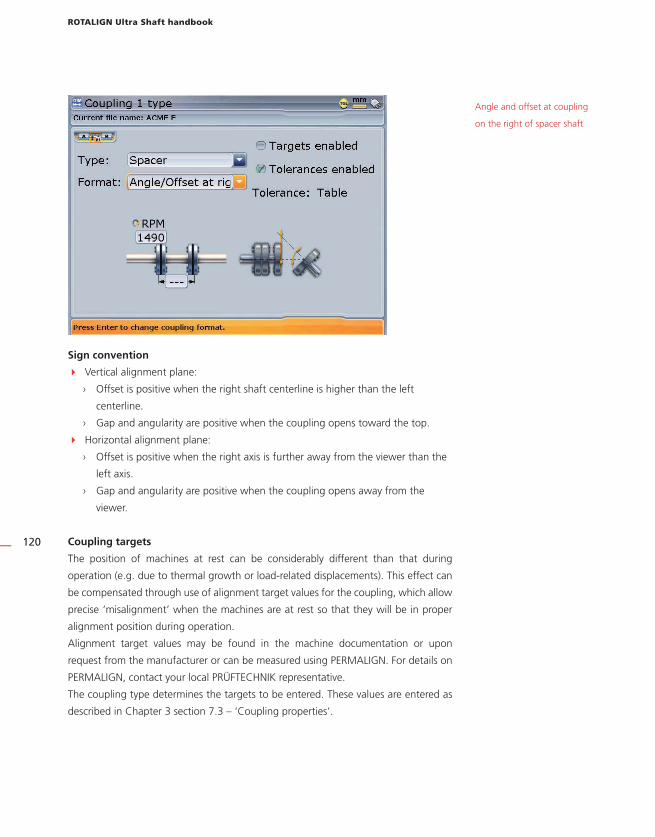
ROTALIGN Ultra Shaft handbook
120
Sign convention
� Vertical alignment plane:
› Offset is positive when the right shaft centerline is higher than the left
centerline.
› Gap and angularity are positive when the coupling opens toward the top.
� Horizontal alignment plane:
› Offset is positive when the right axis is further away from the viewer than the
left axis.
› Gap and angularity are positive when the coupling opens away from the
viewer.
Coupling targets
The position of machines at rest can be considerably different than that during
operation (e.g. due to thermal growth or load-related displacements). This effect can
be compensated through use of alignment target values for the coupling, which allow
precise ‘misalignment’ when the machines are at rest so that they will be in proper
alignment position during operation.
Alignment target values may be found in the machine documentation or upon
request from the manufacturer or can be measured using PERMALIGN. For details on
PERMALIGN, contact your local PRÜFTECHNIK representative.
The coupling type determines the targets to be entered. These values are entered as
described in Chapter 3 section 7.3 – ‘Coupling properties’.
Angle and offset at coupling
on the right of spacer shaft

Special alignment options
121
Tolerances
Alignment quality is evaluated through comparison with tolerances based upon
entered machine dimensions and RPM.
The tolerance ranges are compiled as tables according to coupling type and diameter
as well as RPM. When the coupling type is spacer, the tolerance table values are
determined by the length of the spacer shaft and the RPM. (See suggested shaft
alignment tolerances at the end of chapter 5.)
In ROTALIGN Ultra the ‘live’ tolerance function can be activated or deactivated from
either the coupling properties window or the tolerances window. When the function
is checked active, the alignment quality is indicated with the ‘smiley’ symbol.
Tolerance tables are viewed as follows:
Access coupling properties as described in chapter 3 section 7.3 ‘Coupling
properties’.
Press q. The context menu appears. Use f/g to select ‘Tolerance’.
Press e to confirm selection. The tolerance screen appears.

ROTALIGN Ultra Shaft handbook
122
The given alignment tolerances are based upon standard industry norms and
must not be exceeded, and they are to be used only if existing in-house standards
or the machine or coupling manufacturer has not given any binding values.
Thermal growth calculator
Machine conditions change from the time the machine is off line to when it is running
under normal operating conditions. Some of these changes are due to process forces
(e.g. fluid pressures, airflow). The most notable of these changes is the change in
the temperature of the machine bearings and supports. This is called the machine’s
thermal growth.
ROTALIGN Ultra may be used to calculate thermal growth compensation if no other
values are available. Thermal growth is calculated from the material characteristics,
expected temperature difference and height of the shaft centerline above the shim
plane.
ADVANCED
The given alignment tolerances are based upon standard industry norms and
must not be exceeded, and they are to be used only if existing in-house standards
or the machine or coupling manufacturer has not given any binding values.
ADVANCED
Alignment tolerances are
divided into two quality
ranges -’acceptable’ values
are relatively generous and
intended for noncritical
machines and RPM ranges;
‘excellent’ values are
intended for machines and
RPM ranges that require
especially accurate shaft
alignment.
The tolerance table drop
down menu shows all
tolerances available for the
coupling type selected.
The RPM can be edited
by highlighting the value
and then entering required
value directly using the data
entry keys. Confirm entry by
pressing either e or ß.
�Note

Special alignment options
123
Thermal growth is calculated as follows:
From machine set-up, use the navigation keys to highlight the machine whose
thermal growth requires calculating.
With the machine highlighted, press e to access the machine properties
screen.
Press q. The context menu appears. Use f/g to select ‘Thermal
growth’.
Press e. The thermal growth screen appears.
Press q. The context menu appears. Use f/g to select ‘Thermal
calculator’.

ROTALIGN Ultra Shaft handbook
124
Press e to access the thermal calculator screen.
Proceed to select type of material using the drop down menu.
Use the navigation keys to highlight the respective value boxes and enter directly,
the ambient temperature, the machine running temperature and the distance
from machine base to the shaft centerline using the data entry keys.
In the example opposite, the
motor material is cast iron,
the ambient temperature is
25°C, the machine running
temperature is 120° C
and the distance from the
bottom of the turbine feet
to the shaft centerline is 70
cm. This gives a growth of
0.71 mm.

Soft foot
125
4.5 Soft foot
SOFT FOOT is the condition of machine frame distortion. Any cause that results in
machine frame distortion when the machine is anchored to its foundation is a soft
foot. Some principal causes are:
› Non-coplanar machine mounting surfaces,
› Deformed machine frame or feet,
› External forces e.g. from connecting pipe or bracket,
› Improper shimming or dirty machine feet.
› Too many shims under a machine foot (a maximum of 3 should be used)
The consequences of forcibly tightening down the feet are deformed machine
frames, bent shafts and distorted bearings. This leads to high vibration and premature
failure.
Soft foot should be checked before aligning the shafts, and this can be done quickly
and conveniently with the aid of the ROTALIGN Ultra soft foot function. With the laser
and sensor mounted on the shaft in the usual way, the system is able to sense any
machine movement when the machine bolts are loosened individually. By entering the
machine dimensions, the computer is able to calculate, from shaft movement, by how
much each foot has moved as it is loosened.
Once foot movements have been established, the results are interpreted and
translated into shim thicknesses to be placed under the feet. How straightforward
this is, depends on the type of soft foot present.
Parallel soft foot
One or more feet are
too short or too long.
This usually results in the
machine rocking on the
longer feet. This is corrected
by shimming the shorter
feet.
Angular soft foot
The base of the foot is at
an angle to its foundation
and they are only partly in
contact. In this case, suspect
foot is checked with a feeler
gauge and corrected by
building a custom ‘shim
wedge’ or machining the
underside of the foot

ROTALIGN Ultra Shaft handbook
126
Checking and correcting soft foot conditions
The three main types are parallel soft foot, angular soft foot, and induced soft foot.
There are instances where the soft foot is a combination of two or more types.
Checking for soft foot is part of machine and job preparation.
The machine(s) to be measured should be treated first as normal four-feet
machines. A machine with 6 or more feet is set up and measured like a
four-footed machine (provided it is a compact rigid frame), with all the middle
feet left loose, and after soft foot is corrected at the four main supports, the rest
are feeler gauged and shimmed according to the feeler gauge readings or dial
indicator readings on the foot itself.
The measurement procedure
Soft foot may be measured from virtually any screen.
1. Mount the laser and the sensor in the normal way, and then switch on the laser.
Adjust the beam onto center of the sensor dust cap.
2. Remove the sensor dust cap.
3. Use the navigation keys to highlight machine whose feet are to be measured.
4. With the machine highlighted, press q. The context menu appears. Use the
navigation keys to highlight .
The machine(s) to be measured should be treated first as normal four-feet
machines. A machine with 6 or more feet is set up and measured like a
four-footed machine (provided it is a compact rigid frame), with all the middle
feet left loose, and after soft foot is corrected at the four main supports, the rest
are feeler gauged and shimmed according to the feeler gauge readings or dial
indicator readings on the foot itself.
�Note
Soft foot may be measured from virtually any screen.
�Note

Soft foot
127
5. Press e to confirm selection. If the laser is centered the following screen
appears.
6. Press e to continue with soft foot measurement. If however, the laser beam is
not centered, press q. The context bar appears. Use f/g to highlight
‘XY view’.
7. Press e to access the XY view screen.

ROTALIGN Ultra Shaft handbook
128
8. Use the adjustment thumbwheels to center the laser beam. Use the top
thumbwheel to move the beam up/down. The side thumbwheel is used to move
the beam sideways.
9. After centering the laser beam, press ß to return to the soft foot screen. Press
e to proceed with measurement.

Soft foot
129
10. With foot to be measured highlighted, press e. A wrench symbol appears on
the screen. Loosen the corresponding foot bolt. When the displayed value no
longer rises, press e. The wrench symbol disappears and the highlight springs
to the next empty value box. Tighten the bolt.
11. Repeat step 10 for each machine foot. You may use the navigation keys to
highlight any foot to measure.
If machine dimensions have
not been entered, pressing
e prompts the entering
of the missing dimension.

ROTALIGN Ultra Shaft handbook
130
12. To correct soft foot, press q. The context menu appears. Use f/g to
highlight ‘Diagnose’. ROTALIGN Ultra presents the user with concise instructions
on how to eliminate the prevailing soft foot.
13. Press e to proceed. A hint appears requesting confirmation as to whether the
sof foot measurement should be ended and diagnosis started.
In this example, soft foot
has been detected and
must be eliminated before
proceeding with the
alignment of the machines.
ADVANCED

Soft foot
131
14. Use i/h to highlight ‘Yes’ confirming selection by pressing e, then proceed
with diagnosis using the soft foot wizard.
15. Proceed with wizard instructions to find a solution to the detected soft foot by
highlighting ‘Next’ using the navigation keys then pressing e.
The wizard screen indicates
that induced soft foot has
been detected.

ROTALIGN Ultra Shaft handbook
132
16. Follow the wizard instructions by highlighting ‘Next’ using the navigation keys
then pressing e until the diagnosis and correction is completed.
17. After correcting the soft foot, continue with alignment of the machines.
The wizard offers the
relevant remedy instructions
for each different soft foot
situation.
133
Chapter 5: Updating ROTALIGN Ultra
firmware
Updating ROTALIGN® Ultra to version 2.1x
Current ROTALIGN Ultra firmware updates are carried out with the use of the
especially approved PRÜFTECHNIK 1 GB USB memory stick (aka jumpdrive).
Old PRÜFTECHNIK memory sticks must be disposed of in in accordance to the
directive on Waste Electrical and Electronic Equipment (WEEE).
The necessary update may be downloaded from the PRÜFTECHNIK website.
1. Transferring update files to the memory stick
If you are acquiring the update via the website, you will require to transfer it to the
approved memory stick before commencing the upgrading.
2. Downloading the update from the PRÜFTECHNIK website
a) Go to: <http://www.pruftechnik.com/alignment-systems/press-and-downloads/
software-and-firmware-downloads/rotalign-ultra.html>.
Download the upgrade to a folder on your PC. It is a large file, this may take
several minutes.
DO NOT download directly to your approved memory stick!
If you had previously carried out an update using the memory stick, ensure that
you DELETE all old folders.
b) Connect the approved PRÜFTECHNIK memory stick with not less than 100 MB of
free space to your PC. Double-click the “ROTALIGN_Ultra_Firmware_2.1x.exe”
file in your PC. You will be prompted to extract the file to a memory stick (See
the next screen).
�Note
Current ROTALIGN Ultra firmware updates are carried out with the use of the
especially approved PRÜFTECHNIK 1 GB USB memory stick (aka jumpdrive).
Old PRÜFTECHNIK memory sticks must be disposed of in in accordance to the
directive on Waste Electrical and Electronic Equipment (WEEE).
�Note
DO NOT download directly to your approved memory stick!
If you had previously carried out an update using the memory stick, ensure that
you DELETE all old folders.
The following approved
PRÜFTECHNIK memory
sticks may also be used:
ALI 4.451-128 and
ALI 4.451-256
Firmware update

ROTALIGN Ultra Shaft handbook
134
c) Select the location of your memory stick with ‘Browse’. Then click ‘Install’. The
files extraction process begins.
d) If the extraction has been successful, the update is now on the memory stick,
and you may proceed to section 3 - ‘Carrying out the firmware update.

135
3. Carrying out the firmware update
Before starting the upgrade verify that your memory stick has the files shown below
in the ‘Ultra’ directory.
a) Connect your ROTALIGN® Ultra to the mains adapter/charger, or ensure that the
rechargeable battery is fully charged.
b) Switch ROTALIGN® Ultra on and wait for Program Manager screen to appear.
�Note
Firmware update

ROTALIGN Ultra Shaft handbook
136
c) Attach the ‘short’ USB/peripheral devices cable ALI 12.503 to your ROTALIGN
Ultra.
d) Insert the approved PRÜFTECHNIK memory stick ALI 4.451-1G into the ‘short’
USB cable.
e) On inserting the memory stick, ROTALIGN Ultra beeps and all 4 alignment
condition LEDs blink followed by the screen below
Should the firmware on
the memory stick be of
the same version as that
present on the instrument,
the instrument beeps and
the 4 LEDs will blink but
no update action will take
place.

137
You are about to start the upgrade process therefore pay special attention to the
hints appearing on the display. Do not remove the memory stick during the entire
upgrade process. This may take up to 15 minutes.
To start the upgrade process press and hold down e until the device resets.
DO NOT be irritated by the hint as to whether you want to turn off the instru-
ment or not.
f) The “Flashing firmware” screen as shown next appears with the hint not to turn
off the device.
g) When the final flashing phase is completed, the hint “Verifying the last firmware
upgrade flashing” appears on the display with the 4 LEDs blinking continuously.
h) After the automatic update is completed, the next screen appears.
�Note
You are about to start the upgrade process therefore pay special attention to the
hints appearing on the display. Do not remove the memory stick during the entire
upgrade process. This may take up to 15 minutes.
To start the upgrade process press and hold down e until the device resets.
DO NOT be irritated by the hint as to whether you want to turn off the instru-
ment or not.
The following messages
appear on the numbered
locations on the screen
opposite:1 "Flashing firmware...
Do not turn the device off" 2 "flashing firmware 1
Transducer firmware update
1
2
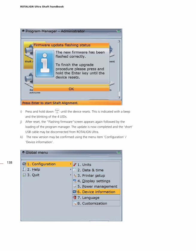
ROTALIGN Ultra Shaft handbook
138
i) Press and hold down e until the device resets. This is indicated with a beep
and the blinking of the 4 LEDs.
j) After reset, the “Flashing firmware“screen appears again followed by the
loading of the program manager. The update is now completed and the ‘short‘
USB cable may be disconnected from ROTALIGN Ultra.
k) The new version may be confirmed using the menu item ‘Configuration‘ /
‘Device information‘.

139
Chapter 6: Special applications
This chapter deals with alignment of machines that require use of special procedures
rather than those for the standard horizontal alignment. These special applications
include:
� Machine trains (groups of up to 14 machines coupled together for Advanced
Shaft and groups of up to 6 machines coupled together for Lite Shaft)
� Cardan drive machines
� Flanged machines (mounted vertically or horizontally)
6.1 Machine train alignment Set-up
a. After starting the alignment application, either select a suitable template or
configure the machines as appropriate.
b. To select a suitable template, press q while in the set-up screen. The context
menu appears.
c. Use f/g to select ‘File’/’New’.
d. Press e. The ‘Open template’ screen appears. Use f/g to select
required template.
Machine train

ROTALIGN® Ultra Shaft handbook
140
After highlighting the required template, confirm selection by pressing e.
e. Multiple machine trains can also be configured from the set-up screen. Press q
The context menu appears. Use f/g to highlight ‘Add left’ or ‘Add right’
depending on which end of the machine train a machine is to be added.
After highlighting the required train end, confirm selection by pressing e.
f. After either selecting an appropriate template or configuring the machine train,
proceed to define the machines and enter the corresponding dimensions as
detailed in chapter 3.
With the context menu
displayed, pressing 7 or
8 automatically adds a
machine to the right or left
end of the machine train
respectively.

141
How to align machinery trains
The following step-by-step approach is recommended for multi-element trains.
a. Measure alignment at each coupling
b. Display results and optimize corrections (by defining ‘stationary’ machine feet)
c. Align two machines (remount sensors if necessary)
d. Check alignment results
e. Align the next two machines and repeat alignment check
f. Repeat step (e) until all machines have been aligned.
Machine elements in view
are highlighted
Machine train

ROTALIGN® Ultra Shaft handbook
142
Measurement
a. While in the set-up screen, use f to zoom out the machine train. Pressing
the key repeatedly will zoom out until the entire machine train fills the display
screen.
b. Use h/i to select the machine coupling to be measured first.
c. Ensure the laser is mounted on the left side of the selected coupling.
d. Remove the dust cap from the laser and switch it on. Leave the sensor dust cap
on.
e. Press m and adjust the beam onto the sensor (see chapter 3).
f. Proceed to carry out measurement as described in chapter 3, observing the
requirements for valid measurement – shafts must be turned by at least 60°, a
minimum of 3 measurement points to be taken.
g. Press e to stop measurement.
If the measurement mode used is not continuous sweep, measurement is
stopped by pressing q and then highlighting ‘Stop’, and confirming selection
by pressing e.
h. Switch the laser off and mount the laser and sensor across the next coupling.
i. While in ‘Measure’, press and hold h/i to move to the next coupling to be
measured.
Please make sure when moving the laser and sensor to each coupling that the
dimension from sensor to coupling center is entered correctly in the dimensions
screen.
To view any respective part
of the train closely, highlight
the section using h/i
then zoom in by pressing
g.
�Note
A machine train of up to a
maximum of 14 machines
(13 couplings) can be
configured [Advanced
Shaft]. You may view the
entire machine train at
once through the ‚zoom
out‘ function, however,
the maximum number of
machines for which all
dimensions can be viewed
at one time is 5 machines
(4 couplings) Simply use
h/i to scroll through
the machines in the train.
While in the measurement
screen, you may jump to
the desired coupling to be
measured by pressing and
holding h/i.
Always make sure
the coupling you are
measuring is the one
actually highlighted in the
machine train!
If the measurement mode used is not continuous sweep, measurement is
stopped by pressing q and then highlighting ‘Stop’, and confirming selection
by pressing e.
Please make sure when moving the laser and sensor to each coupling that the
dimension from sensor to coupling center is entered correctly in the dimensions
screen.�
Note

143
l. Repeat the measurement procedure (step c through h) until measurements have
been taken across all couplings.
Evaluating results
a. Press RES to view the alignment results at the individual couplings.
b. To view the results at the next coupling, press q and use f/g to
highlight the direction arrow to the next coupling or, simply press and hold
h/i to jump to the next coupling in the train.
c. Press e to view the alignment results at the next coupling.
Highlights coupling being
viewed
Machine train

ROTALIGN® Ultra Shaft handbook
144
d. To view the alignment results of the entire machine train, press f and hold
to zoom out the train, or simply press RES .
6.2 Cardan shaft alignmentThis section describes the aligning of cardan shafts using the cardan shaft bracket lite
ALI 2.874 SET in conjunction with ROTALIGN Ultra. Cardan drives are installed and
operate with a large offset between the driver and the driven shaft. The spacer shaft
is set at a considerable angle (usually 4° to 6°) in order to ensure sufficient lubricant
circulation, which in turn prevents the universal joints from seizing. Excessive misalign-
ment of such a configuration leads to rapid fluctuation of the driven shaft RPM during
After deciding on which
pair of machines to move
in a train, you may need
to reinstall and readjust
the laser and sensor across
the chosen coupling. Be
sure to install the sensor
at exactly the same
location on the shaft or
coupling as previously. If
you discover later that you
made a mistake, you can
always correct the sensor-
to-coupling dimension
in the Measurement
table individually for any
alignment measurement
or move, without
affecting any of the other
measurements or moves.

145
operation, which holds grave consequences for electronically-controlled synchronous
and asynchronous AC drive motors.
Precise alignment reduces the rotational irregularities of the cardan shaft to a minimum,
so that the uneven bearing loading during cardan shaft rotation is also minimized, the
service life of the components is extended and the chance of unexpected machine
failure is reduced.
The measurement procedure described here allows precise measurement of machines
joined by cardan shafts over distances of up to 3 m (10 ft) and shaft offsets of up to
400 mm (15 3/4 in.) using ROTALIGN Ultra.
1. Mounting the faceplate to the rail
a. Slide the the faceplate down the rail as shown in figure (1a) below. The four
T-nuts should sit in the grooves.
b. After positioning the faceplate on the rail, tighten the four socket head screws
using the provided M6 allen key.
c. Mount the bracket assembly to the coupling face of the non-rotatable shaft. If
the coupling face has a raised rim, the precision machined spacers are used as
shown in order to separate the bracket faceplate from the coupling face.
(Without the spacers, there would be no direct contact between the faceplate and
the coupling surface surrounding the bolt holes – exactly the location where the
faceplate and coupling are being joined.) The washers prevent the nuts from marking
the coupling surface when tightened.
Depending on the relative positions of the machines joined by the cardan shaft, an
inclinometer or spirit level should be used to position the bracket assembly at the
same angle as the cardan shaft when installed, before tightening down the bolts. A
design drawing from the machine manufacturer can be helpful in determining the
intended horizontal and/or vertical offset between the machine coupling halves. The
inclination can be calculated from these horizontal and vertical distances as follows:
Inclination = arctan (vertical offset / horizontal offset)
1a 1b 1c
Cardan drives

ROTALIGN® Ultra Shaft handbook
146
2. Mounting the laser holder assembly on to the rail
a. Loosen the handwheel slightly, then slide the laser holder assembly down the
center groove of the rail, with the T-nut acting as a guide.
b. Fasten the laser holder assembly onto the rail at the appropriate position by
tightening the handwheel.
3. Mounting and adjusting the ROTALIGN laser
a. Slide the two black distance sleeves down the support posts.
b. Slide the laser onto the posts until it rests on the distance sleeves.
c. Mark a set of target crosshairs on the shaft rotation centerline of the other
machine coupling (if the flange has a center hole, a dust cap can be inserted to
provide a temporary target surface).
d. Switch on the laser and adjust the beam to strike the center of the target on the
opposite coupling:
Prior to mounting the laser, adjust both yellow adjustment thumbwheels to the
approximate center of their travel range so that the laser beam is emitted as
straight as possible.
› For rough adjustment, loosen the handwheel and slide the holder along the
rail; loosen the yellow locking knobs to adjust the beam height.
› For fine adjustment, use the thumbwheels on the laser housing to center the
laser beam onto the target.
If a specific offset
between the driver and
driven machine shaft
centerlines is desired, slide
the laser holder along the
rail to a point where its
own centerline of rotation
is located precisely at this
desired amount of offset
from the centerline of
rotation of the coupling
to which the faceplate is
attached.
Prior to mounting the laser, adjust both yellow adjustment thumbwheels to the
approximate center of their travel range so that the laser beam is emitted as
straight as possible.
2a
3b
�Note

147
e. Rotate the laser holder one complete revolution. The laser beam should not drift
from its target at any time; if the laser drifts away from the target, repeat the
previous step.
To adjust the beam, note start position of the beam, then rotate the laser holder
180°. Note position of the beam. Return to the start position and using the
yellow adjustment thumbwheels, adjust the beam in the horizontal and vertical
directions to a position midway between the beam’s start position and 180°
position. Repeat this process until you can rotate the laser holder through one
complete revolution without the beam moving from its original position.
f. Switch off the laser and remove it from its holder.
g. Using the provided M5 allen key, loosen the support posts and slide them
through the bracket frame so that they protrude from the other side.
h. Remount the laser onto the support posts
i. Use the chain-type bracket to mount the sensor on the opposite machine shaft,
then connect it to the ROTALIGN Ultra computer.
j. Switch the laser back on, then adjust the beam onto the sensor (refer to ‘Laser
beam adjustment’ in chapter 3).
To adjust the beam, note start position of the beam, then rotate the laser holder
180°. Note position of the beam. Return to the start position and using the
yellow adjustment thumbwheels, adjust the beam in the horizontal and vertical
directions to a position midway between the beam’s start position and 180°
position. Repeat this process until you can rotate the laser holder through one
complete revolution without the beam moving from its original position.
3e3i
Cardan drives
�Note

ROTALIGN® Ultra Shaft handbook
148
4. Set-up and measurement
a. Switch on the ROTALIGN Ultra computer.
b. Set up the machines (refer to chapter 3) and select the coupling type ‘cardan
shaft’.
c. Remove the sensor dustcap and press m. The laser beam location should be
apparent in the adjustment screen.
d. Press q. A context menu appears. Use the context menu item ‘Mode’ to
select the ‘Multipoint’ measurement mode. (For details about this mode refer to
chapter 4.)
e. Place the specially designed beam adjustment cap (ALI 3.606 UN) that helps
with monitoring the position of the beam during rotation on the sensor lens and
center laser beam (for details to ‘laser beam adjustment’ refer to chapter 3).
In this configuration, the
coupling type display format
selected is ‘Angle’
If “Pass mode”
measurement is used,
please refer to the relevant
technical information
which is available from
your local PRÜFTECHNIK
representative.
Laser beam
Sensor
Adjust laser beam
Laser crosses
sensor Y axis (measurement)4e 4h

149
f. Press e to take the first measurement.
g. Rotate the sensor to the next measurement position.
h. Turn the laser-side shaft and observe the detector view in the measurement
screen (above): at the moment when the laser dot crosses the Y-axis, press e
to take the next measurement.
i. Repeat steps g and h to take measurements in at least three positions over at
least 60° of rotation. (Taking more position measurements improves the reliability
of results.).
j. When enough measurement points over at least 60° rotation have been taken,
press e to stop measurement. Alternatively, stop
measurement by pressing
q followed by 9.
Cardan drives

ROTALIGN® Ultra Shaft handbook
150
5. Evaluation and alignment
Since offset does not affect the performance of cardan shafts, only angularity must
be corrected here.
a. Press RES to view alignment results.
A PRÜFTECHNIK cardan shaft tolerance table is available for 1/2° and 1/4° limits.
The tolerance table is accessed via ‘Coupling properties’ (for details refer to
chapter 3).
In this example the
automatic tolerance
evaluation returns a happy
face in both horizontal
and vertical directions. This
indicates that the machines
are aligned within the
specified tolerances and
therefore no further aligning
action may be required.
If a specific amount
of offset between the
machine shafts was
desired and the laser
holder assembly was set
up to this precise offset
as described in step 2b
above, then, after the
angular alignment of
the movable machine
is completed, remount
and readjust the laser
as described in steps 3a
through e and proceed
to adjust the movable
machine in a parallel
manner both vertically
and horizontally until
the beam spot hits the
movable machine shaft‘s
centerline of rotation,
taking care not to change
its angular alignment.
A PRÜFTECHNIK cardan shaft tolerance table is available for 1/2° and 1/4° limits.
The tolerance table is accessed via ‘Coupling properties’ (for details refer to
chapter 3).�Note
The tolerance table may also be accessed as described under ‘Tolerances’ in chapter 4.

151
b. If the machines are out of tolerance, reposition them with the help of the MOVE
function (refer to chapter 3).
c. Remeasure to determine the new alignment condition.
6.3 Flanged machines A typical vertical machine arrangement comprises one machine mounted on top of
the other using a bolted flange.
Flange-mounted machines can be situated vertically or horizontally. In either case,
alignment corrections are made directly at the flange.
Angularity is corrected by inserting or removing shims between the flanges. ROTALIGN
Ultra calculates the shimming thickness for each flange bolt. Offset is corrected by
positioning the flange laterally.
1. Overview - vertical machinery
Before commencing with this section, please acquaint yourself with ‘Horizontal
shaft alignment’ in chapter 3.
The laser and sensor are mounted on either side of the coupling as for horizontal
machines, with the laser on the shaft of the machine designated stationary. The
electronic inclinometer cannot determine the rotation angle of vertical shafts; therefore
measurements must be taken on vertical machines using static measurement mode.
The eight 45° measurement positions used with this procedure must be marked
accordingly on the machine.
Before commencing with this section, please acquaint yourself with ‘Horizontal
shaft alignment’ in chapter 3.
Flanged machines
�Note
A typical vertical machine
arrangement consists of
one machine mounted on
another, bolted together
at a flange

ROTALIGN® Ultra Shaft handbook
152
2. Marking measurement positions
a. Mark a reference position on the coupling housing close to the shaft and in line
with a convenient external reference or flange bolt. Likewise, mark a reference
point on the shaft.
b. Measure the circumference of the shaft and divide by eight.
c. Use this distance to make seven more evenly-spaced marks on the shaft
beginning at your chosen start point. Number the points counterclockwise as
seen from sensor to laser, beginning with 0 first, followed by 1:30, 3:00,4:30,
6:00, 7:30, 9:00 and 10:30.
For circular housings, measure the circumference of the coupling housing and divide by
eight. Use this distance to make eight evenly-spaced marks on the housing beginning
at your chosen start point. Number the points clockwise looking down onto the shaft
with 0 as the first, followed by 1:30, 3:00,4:30, 6:00, 7:30, 9:00 and 10:30.
3. Set-up
a. Mount the laser and sensor on either side of the coupling, ensuring that they are
aligned exactly with the 0 or reference mark.
4:30
0 1:30 3:
00
01:30
3:00
10:30
9:00
2c
Evenly-spaced marks are
made on the bearing
housing beginning with 0 as
the reference and numbered
clockwise looking down
onto the shaft.
2a

153
b. Connect the sensor to ROTALIGN Ultra and switch on the device.
c. Start the shaft alignment application. When the opening set-up screen appears,
press q. The context menu appears. Use f/g to highlight ‘Menu’.
d. Press e to access the global menu, then use the navigation keys to select
‘Machine properties’ / ‘Machine vertical-horizontal setting’.
e. Confirm selection by pressing e. The train orientation screen appears.
The global menu can be
opened directly from this
screen by pressing q
twice.
The train orientation screen
may be accessed directly
from the global menu by
pressing 3 followed by
6.
Flanged machines

ROTALIGN® Ultra Shaft handbook
154
f. Use the navigation keys to select the train orientation ‘Vertical’. Confirm
selection by pressing e. The confirmed machine orientation is depicted on the
screen. Use ß to return to the set-up screen.
g. Configure the machines as appropriate. (Refer to ‘Enter machine dimensions’ in
chapter 3).
h. When entering machine dimensions, the flange geometry must be taken into
account. Use the navigation keys to highlight the flange-mounted machine then
press e. A hint requesting the definiton of the flange appears. Confirm by
pressing e. The flange editing screen shown next appears.

155
i. Use the naviagtion keys to cycle through the flange properties.
› The shape of the flange is selected from the ‘Shape’ drop down menu.
Any one of the following shapes may be selected from the menu: ‘Circle’,
‘Rectangle’, ‘Polygon’
› Flanges can either be face or reverse-mounted. The mounting is selected from
the ‘Mount type’ drop down menu.
› The exact location of the center of the shafts is defined in the boxes ‘Center
X’ and ‘Center Y’
› The number of bolts is edited directly using the data entry keys or f/g › The pattern formed by the bolts is selected from the ‘Layout’ drop down
menu. The following bolt patterns are available: ‘Circle’, ‘Rectangle’, ‘Polygon
› The flange dimensions and bolt pattern lengths are entered directly using the
data entry keys
Details on how to navigate
and edit items on this
screen are discussed under
‘Machine properties’ in
chapter 3.
face-mounted (standard) reverse-mounted
shims
An elliptical flange and
bolt pattern may also be
configured. Simply select
a ‘circle’ flange shape
and ‘circle‘ bolt layout,
then edit the flange
length and width and bolt
pattern length and width
dimensions individually.
Flanged machines

ROTALIGN® Ultra Shaft handbook
156
j. It may be necessary to edit the bolt coordinates. To do this, press q while in
the machine flange screen. The context menu appears.
m. Press 2 to directly access the bolts coordinates screen. This screen shows the
polar and cartesian coordinates of the bolts relative to the chosen shaft center.
Alternatively, the bolts
coordinates screen may
be accessed by using
f/g to highlight
‘Bolts’ then pressing e to
confirm selection.
Use the navigation keys to
highlight the X/Y coordinate
of any bolt position. The
highlighted value may be
directly edited using the
data entry keys.
In this example, the
X-coordinate of bolt number
4 has been highlighted. The
corresponding bolt pattern
position also appears
highlighted.

157
4. Measure
a. After entering the required dimensions, press m and proceed to center the
laser beam.
For vertically oriented machine trains, static measurement mode is selected
automatically.
b. Rotate the shafts to the first measurement position. If using the coupling
housing numbering convention, the reference mark and the measurement
position 0 should be aligned or matched to each other.
c. Press e to take the first measurement point.
d. Rotate shaft to the second measurement position (e.g. 1:30). If the chosen
measurement position does not correspond with the selected position, move the
screen’s red cursor (or ‘hour hand’) to the desired position using the navigation
keys.
e. A minimum of three measurement positions are required to obtain results, but
it is recommended that maximum number of measurement points be taken to
maximize the quality of results.
For vertically oriented machine trains, static measurement mode is selected
automatically. �Note
Flanged machines

ROTALIGN® Ultra Shaft handbook
158
5. Results
a. Press RES to evaluate results.
Sign convention
POSITIVE GAP opens towards 0:00 or 3:00
POSITIVE OFFSET if the top machine is towards 0:00 or 3:00
Remember, viewpoint is always determined by looking from the sensor towards
the laser emitter. Note the little white clock face on the laser serves as a reminder
of this.
Sign convention
POSITIVE GAP opens towards 0:00 or 3:00
POSITIVE OFFSET if the top machine is towards 0:00 or 3:00
Remember, viewpoint is always determined by looking from the sensor towards
the laser emitter. Note the little white clock face on the laser serves as a reminder
of this.
The results screen shows the
coupling gap and coupling
offset in the 0-6 and 3-9
directions. Offset corrections
in the side and top view are
also shown.
In this example, the 0-6
correction indicates moving
the flange by 0.07 mm
towards 0:00 and by 0.16
mm towards 3:00.
The screen values represent
POSITION.
�Note

159
b. To obtain the shimming corrections for each flange bolt, press q while in the
results screen. The context menu appears.
c. With the context menu displayed, press 4. The ‘Flange corrections’ screen
appears.
Flange correction details are displayed only when the cursor is on a movable
element.
Flange correction details are displayed only when the cursor is on a movable
element.
Alternatively, the ‘Flange
corrections’ screen may
be accessed by using
f/g to highlight
‘Details’ and confirming
selection by pressing e.
�Note
The flange corrections
screen shows the shimming
corrections for each flange
bolt. The value for each bolt
position appears on the
shim table and as an inset
next to the flange pattern.
Any bolt position can be
selected by pressing either
p (counterclockwise) or
o (clockwise).
The offset corrections to be
performed on the flange are
displayed along the sides of
the flange schematic.
Flanged machines

ROTALIGN® Ultra Shaft handbook
160
d. To choose the shimming solution best suited for the situation at hand, press q
while in the results screen. The context menu appears.
Use the navigation keys to highlight the appropriate mode, confirming selection
by pressing e.
› (–) mode indicates all negative shimming
› (+) mode indicates all positive shimming
› (±) mode indicates optimized shimming. In this mode, half of the corrections
will positive, and the other half negative.
› (0+) mode indicates zero plus shimming. In this mode, one bolt position is
forced to zero and the rest are positive.
› (0–) mode indicates zero minus shimming. In this mode, one bolt position is
forced to zero and the rest are negative.
Good quality shims such as PERMABLOC, MYLAR and LAMIBLOC should be
used. Contact your local PRÜFTECHNIK representative for details.
Good quality shims such as PERMABLOC, MYLAR and LAMIBLOC should be
used. Contact your local PRÜFTECHNIK representative for details. �Note

161
e. It may be necessary to switch the view from say 0-6 to 9-3, and vice versa. From
the result screen, press q. The context menu appears. Use the navigation keys
to highlight the desired view, confirming selection by pressing e.
f. Offset is corrected using the ‘Move’ function. From the result screen, press q.
The context menu appears.
With the context menu displayed, press 5 to access the live Move screen. A
hint requesting the setting of the sensor angle appears on the screen.
Alternatively, live MOVE
may be accessed by using
f/g to highlight
‘Move’ and confirming
selection by pressing e.
The sensor angle selection
hint appears.
Flanged machines

ROTALIGN® Ultra Shaft handbook
162
g. Use the naviagtion keys to position the sensor image on the screen to
correspond to the physical position of the laser and the sensor. Press e to
confirm selected position. The Move function auto starts.
If the Move function does not auto start, the beam is not centered. ROTALIGN
Ultra will automatically switch to XY view. After centering the laser beam, press
ß and wait for the Move function to auto start.
If the Move function does not auto start, the beam is not centered. ROTALIGN
Ultra will automatically switch to XY view. After centering the laser beam, press
ß and wait for the Move function to auto start. �
Note

163
5. Alignment
It is recommended (but not necessary) to correct angularity first:
a. Loosen the flange bolts and lift the movable machine to a small degree.
b. Adjust shimming to make angularity corrections:
› For face-mounted flanges, insert the indicated thickness of shims between the
flanges at the respective bolt locations.
› For reverse-mounted flanges, insert the indicated thickness of shims behind
the flanges at the respective bolt locations.
c. Tighten the bolts back down, then take another set of readings to confirm
alignment corrections; repeat shimming if necessary.
d. Once satisfied that overall angular misalignment is in tolerance, and no more
shimming is required, proceed to correct offset.
Correcting offset misalignment:
e. Press q while in the results screen. Preferred is a results screen showing both
0-6 and 9-3 alignment results.
f. From the context menu that appears, access live Move by pressing 5.
Alternatively, access live Move by using f/g to highlight ‘Move’ and
confirming selection by pressing e.
g. Ascertain at which position your laser and sensor are located or turn them to any
desired position. Use the navigation keys to match the sensor position on the
screen to the physical position of the laser and sensor. Confirm selected position
by pressing e.
i. Loosen the flange bolts and perform offset corrections in the 0 to 6 and 9 to 3
o’clock directions while monitoring the live Move on the screen.
› Corrections should be brought as close as possible to zero.
› Use appropriate tools (e.g. jackscrews) to position the machine.
› Take care not to let the shims slip out of place during lateral positioning.
j. When offset is in tolerance, tighten the flange bolts. Remeasure to check if the
new alignment condition is in tolerance.
k. If not, repeat the above steps until alignment is in tolerance.
6.4 Flange-mounted horizontal machinesWhen machines are joined by means of flange, their alignment is determined by
inserting the proper combination of shims at the flange bolts and, depending on the
flange type, between the faces of the flanges. The requirements are quite similar to
those for aligning vertical machines.
When the shaft rotates around a horizontal axis, the electronic inclinometer detects
the rotational position during measurement, which may be taken in any desired
measurement mode.
Flanged machines

ROTALIGN® Ultra Shaft handbook
164
Based on the measurements taken, the computer determines the thicknesses of shims
to be fitted between the flanges required to align the shafts.
Alignment procedure
Set-up
a) Mount the laser and sensor on the shaft. The laser mounts on the left machine
and the sensor on the right. This arrangement is identical to the standard
ROTALIGN Ultra screen display for horizontal machines.
b) Switch on ROTALIGN Ultra by pressing e and holding for a few seconds.
When the program manager screen appears, use the navigation keys to highlight
‘Shaft Alignment’. Press e to access the application. The opening template in
the set-up screen appears.
Machine to be
aligned
End view of flange
(as seen from right)
Flange shimming positions 1-4
24
3
1
Laser
Sensor
Configure the machines
directly from this screen as
descibed in chapter 3.
Shown here are the
shimming locations for a
two-bolt flange, a special
case of the normal circular
flange shape.

165
c) Important in this configuration is the flange position and configuration. Edit
these as described in chapter 3.
Flange geometry and dimensions
a) After configuring the machines, proceed to enter all necessary dimensions as
described in chapter 3.
b) Edit the flange geometry by highlighting the flange-mounted machine then
pressing e. A hint requesting the definition of the flange appears. Confirm by
pressing e. The flange editing screen appears.
Flanged machines

ROTALIGN® Ultra Shaft handbook
166
c) Edit the flange geometry as described in section 5.3 (Flanged machines).
Measure
Since the flanged machines under consideration here are mounted horizontally, a
wider choice of measurement methods is available.
a) Press m and proceed to center the laser beam. The desired measurement
method may be selected using the context menu as described in chapter 4.
b) Depending on the measurement mode selected, rotate shafts and take
measurement as described in chapter 3 (continuous sweep measurement mode)
or chapter 4 (other measurement modes).

167
Evaluating results
a) After finishing taking measurements, press RES to evaluate results.
b) To view the flange shimming details, place the cursor on the movable element,
then use the context menu to select the item ‘Details’ (This step has been
described fully in section 5.3 - ‘Flanged machines’)
The flange is depicted as viewed from the right machine toward the left. The bolts
in the figure correspond to the bolts (or shimming positions) on the flange, with the
top position corresponding to number “1”. The respective offset appears on the top
half of the screen.
In this example, the
horizontal offset value is
0.03 mm positive.
The table on the right
lists the calculated shim
corrections. The interpreta-
tion of the shim corrections
has been described in
section 5.3 – ‘Flanged
machines’.
Flanged machines

ROTALIGN® Ultra Shaft handbook
168
Shimming
Loosen the bolts and fit the shims according to the values given in the table. Try to
avoid any lateral movement of the machine while doing so. When finished, retighten
bolts.
Remeasure
Press m and take a new set of readings before beginning offset corrections. The
results should now show little if any shimming corrections.
Live Move to eliminate offset
Start live Move as described in section 6.3 - ‘Flanged machines’.
Do not loosen the machine anchor bolts until live Move starts. Move the machine
laterally (for horizontal) while viewing the screen. Jack bolts or other mechanical or
hydraulic adjustment methods are recommended for best results. Tighten down the
anchor bolts, then press e to conclude the horizontal alignment procedure.
Final check
Press m and take another set of readings in order to confirm the alignment
condition.
Remove the components from the shaft before switching on the machine!Remove the components from the shaft before switching on the machine! �WARNING

Appendix
169
Appendix
Suggested shaft alignment tolerances
[RPM] metric [mm] inch [mils]
Soft foot any 0.06 mm 2.0 mils
Short “flexible” couplings
Offset
Acceptable Excellent Acceptable Excellent
600 9.0 5.0
750 0.19 0.09
1500 0.09 0.06
1800 3.0 2.0
3000 0.06 0.03
3600 1.5 1.0
6000 0.03 0.02
7200 1.0 0.5
Angularity
(coupling gap difference
per 100 mm or 10”
diameter
600 15.0 10.0
750 0.13 0.09
1500 0.07 0.05
1800 5.0 3.0
3000 0.04 0.03
3600 3.0 2.0
6000 0.03 0.02
7200 2.0 1.0
[continued]
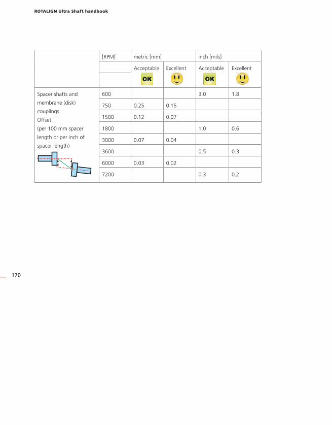
ROTALIGN Ultra Shaft handbook
170
[RPM] metric [mm] inch [mils]
Acceptable Excellent Acceptable Excellent
Spacer shafts and
membrane (disk)
couplings
Offset
(per 100 mm spacer
length or per inch of
spacer length)
600 3.0 1.8
750 0.25 0.15
1500 0.12 0.07
1800 1.0 0.6
3000 0.07 0.04
3600 0.5 0.3
6000 0.03 0.02
7200 0.3 0.2

Appendix
171
ROTALIGN Ultra technical data
Computer
CPU Intel XScale® Processor 520 MHz
Memory 64 MB RAM, 64 MB Internal Flash,1024 MB Compact Flash Memory
Display Type: Transmissive (sunlight-readable) backlit TFT colour graphic display
Resolution: Full VGA, 640 x 480 Pixel
Dimensions: 5.7 inch diagonal
Keyboard elements: Navigation cursor cross with up, clear and menu keys; Alphanumeric keyboard with dimensions, measure and results hard keys
LED indicators 4 LEDs for laser status and alignment condition
2 LEDs for wireless communication and battery status
Power supply Operating time: 25 hours (using Li-Ion rechargeable battery) 12 hours (using disposable batteries) typical use (based upon an operating cycle of 25% measurement, 25% computation and 50% ‘sleep’ mode)
Disposable batteries: 6 x 1.5 V IEC LR14 (“C“)
Lithium-Ion rechargeable battery: 7.2 V / 6.0 Ah (optional)
External interface 2 x USB host for printer, keyboard or PC communication
1 x USB slave for printer, keyboard or PC communication
RS232 (serial) for sensorI-Data socket for sensorEthernet
Integrated wireless communication, class 1, transmitting power 100 mW
AC adapter/charger socket
Environmental protection IP 65 (dustproof and water spray resistant), shockproof
Relative humidity 10% to 90%
Temperature range Operation: 0°C to 45°C [32°F to 113°F]
Storage: -20°C to 60°C [-4°F to 140°F]
Dimensions Approx. 243 x 172 x 61 mm [9 9/16” x 6 3/4” x 2 3/8”]
Weight 1 kg / 2.2 lbs (without battery)
CE conformity EC guidelines for electric devices (2004/108 EWG) are fulfilled
Sensor
Particulars 5-axis sensor: 2 planes (4 displacement axes), 1 inclination 360°
Environmental protection: IP 67 (submersible, dustproof)
Ambient light protection: yes
Storage temperature: -20°C to 80°C [-4°F to 176°F]
Operating temperature: 0°C to 60°C [32°F to 140°F]
Dimensions: approx. 105 x 67 x 47 mm [4 5/32” x 2 5/8” x 1 55/64”]
Weight: approx. 190 g [6 7/10 oz.]
Measurement area: unlimited, dynamically extendible (U.S. Patent 6,040,903)
Resolution: 1 μm (0.04 mil) and angular 10 μRad
Accuracy (avg): > 98%
Measurement rate: approx. 20 Hz
continued
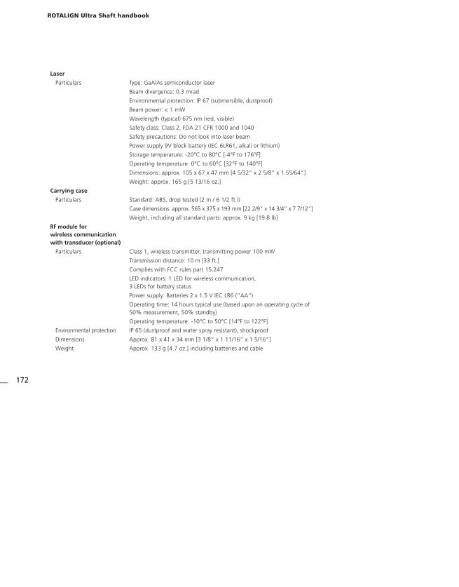
ROTALIGN Ultra Shaft handbook
172
Laser
Particulars Type: GaAlAs semiconductor laser
Beam divergence: 0.3 mrad
Environmental protection: IP 67 (submersible, dustproof)
Beam power: < 1 mW
Wavelength (typical) 675 nm (red, visible)
Safety class: Class 2, FDA 21 CFR 1000 and 1040
Safety precautions: Do not look into laser beam
Power supply 9V block battery (IEC 6LR61, alkali or lithium)
Storage temperature: -20°C to 80°C [-4°F to 176°F]
Operating temperature: 0°C to 60°C [32°F to 140°F]
Dimensions: approx. 105 x 67 x 47 mm [4 5/32” x 2 5/8” x 1 55/64”]
Weight: approx. 165 g [5 13/16 oz.]
Carrying case
Particulars Standard: ABS, drop tested (2 m / 6 1/2 ft.))
Case dimensions: approx. 565 x 375 x 193 mm [22 2/9” x 14 3/4” x 7 7/12”]
Weight, including all standard parts: approx. 9 kg [19.8 lb]
RF module for wireless communication with transducer (optional)
Particulars Class 1, wireless transmitter, transmitting power 100 mW
Transmission distance: 10 m [33 ft.]
Complies with FCC rules part 15.247
LED indicators: 1 LED for wireless communication, 3 LEDs for battery status
Power supply: Batteries 2 x 1.5 V IEC LR6 (“AA“)
Operating time: 14 hours typical use (based upon an operating cycle of 50% measurement, 50% standby)
Operating temperature: -10°C to 50°C [14°F to 122°F]
Environmental protection IP 65 (dustproof and water spray resistant), shockproof
Dimensions Approx. 81 x 41 x 34 mm [3 1/8” x 1 11/16” x 1 5/16”]
Weight Approx. 133 g [4.7 oz.] including batteries and cable

Index
173
Index0 0739 1055
allen key (2.5 mm) 93-D format
machine display 483D mode
context menu 48
A
Adjusting
laser 146Adjustment thumbwheels 60Adjustment tube
ALI 3.608 60Advanced Shaft
firmware registration certificate
ALI 4.741 86Advanced Shaft version 42ALI 2.113 SET
compact chain-type bracket set 7ALI 2.230 93ALI 2.905
lens cleaning cloth 7ALI 3.581-2
RS232 interface 14
sensor cable 6, 16ALI 3.588
tape measure 7ALI 3.600
sensor 5ALI 3.606 UN
beam adjustment cap 148ALI 3.608
adjustment tube 6ALI 3.610
laser emitter 5ALI 4.000/2 9ALI 4.000/2-L
ROTALIGN Ultra Lite Shaft package 5ALI 4.202
ROTALIGN Ultra computer 5ALI 4.410 10ALI 4.451
USB memory stick 9ALI 4.505-0,2 64ALI 4.605
disposable battery housing 10ALI 4.615
desktop charging station 10
ALI 4.620 SET 10ALI 4.741-L 9ALI 4.800
ROTALIGN Ultra case 5ALI 9.638.G
shims mailing insert 8ALI 9.844.G
Shaft pocket guide 7ALI 9.855.G
Shaft operating instructions 7ALI 12.502-2
PC cable
OPTALIGN smart 6ALI 12.503
USB cable 6
USB host 14ALI 12.651.I
ac power supply/charger 6ALI 13.700 CDS 8ALI 13.700 CD SET
ALIGNMENT CENTER/Resources
CD 8ALI 13.701 CD
ALIGNMENT REPORTER CD 8Alignment quality
tolerances 71Alignment targets 43Anchor peg 44Angularity 169
corrections 163Angular soft foot 125Appendix 169Assigning labels 100Auto measurement
activation 36Averaging 109
setting 109
B
Batteries
‘C’ size 13
replacing 15Battery charger
ALI 12.651 13Battery compartment
ALI 4.605 13Beep 32Bolt coordinates 156Bolt position 156, 159

ROTALIGN Ultra Shaft handbook
174
Bracketscompact chain-type 45
mounting 44Brightness 29
C
Cable clip 45Calibration 16Cardan drive machines 139Cardan shaft 113Cardan shaft alignment 144Cardan shaft bracket lite
ALI 2.874 SET 144CE compliance 11Charger socket 14Check mark 99Context menu 33Continuous sweep 62Continuous sweep mode 89Coupling format
cardan shafts 116
spacer shaft 117Coupling properties 55Coupling target
edit 57Coupling targets 56, 120Coupling type 55Customization 32, 52, 54, 55, 56
D
Date and time
format 24
setting 23Default view 70Deleting measurent 102Device configuration 22Device info 28Dial gauge 62Dial gauge mode 94Display
color TFT
full VGA 12Distance marking
laser 50
E
EC Guidelines 11Editing box 48Electronic inclinometer 16, 151Elliptical flange 155
EMCelectromagnetic compatibility 11
Extend
option 107
F
FCC rules
part 15.247 64FDA 12Firmware registration certificate
Advanced Shaft
ALI 4.741 5
ALI 4.741 41Fixation 52Flange
face-mounted 155
reverse-mounted 155Flange corrections 159Flanged machines 139, 151Flange geometry 165Flange properties 155Function keys 13
G
Global menu 34, 79, 97, 99
standard deviation 92
H
History labels
identifying 103Horizontal machines
flange-mounted 163
I
Inclinometer
external 90IP 65 11
J
Job completion 86Job preparation
machine alignment 43
L
Language
selection 25

Index
175
LaserALI 3.610 15
class II 11
mounting 45
replacing battery 17
wavelength 12, 15Laser battery 15Laser beam
adjustment 60Laser safety 11Lateral positioning 77Licence code 42Licence manager 41Lite Shaft version 42Live Move 76, 109
horizontal 75
vertical 75
M
Machine properties 51Machinery trains
aligning 141Machine train
multiple couplings 142Machine trains 139Magnetic sliding bracket
ALI 2.230 91Measurement files
print report 81
saving 79Measurement mode
dial gauge 89
multipoint 89
pass 89
static 89Measurement modes 62Measurement range
extending 107Measurement screen
automatic 61Measurement table 93, 97, 98
average calculation 99Memory stick
ALI 4.451-128 85Mounting 111
faceplate
cardan shaft 145
laser 146
type 53
Movelateral positioning 75
Move simulator 72
movement value factor 74
move step 73Multipoint 90Multipoint measurement 62MYLAR
shims 160
N
Navigation keys 13Navigation scheme 33Nonrotatable shafts 91
O
Offset
corrections 163Operating keys 12
P
Parallel soft foot 125Pass mode 62, 91PERMALIGN 120Power management 26Power supply 13Printer
set-up 27Program manager 21
R
Raw data
editing 105Rechargeable battery
ALI 4.603 13
NiCad 15Report 82, 83Results options 69Resume policy 33RF module
ALI 4.621 64
delete 67
LED indicators 65
optional 16, 64ROTALIGN Ultra product catalog
DOC 4.900.de/en 8RPM ranges 122RS232 socket 14

ROTALIGN Ultra Shaft handbook
176
S
Safety notes 11Safety rating
class II 15Safety symbols 11Saving report
PDF 83Sensor
ALI 3.600 16
distance marking 50
mounting 45Sensor cable
ALI 3.581-2 46Sensor socket 14Serial number
ROTALIGN Ultra 28Shaft Alignment firmware certificate
ALI 4.741 9Shimming 71, 75, 76, 168Shims
LAMIBLOC 76, 160
MYLAR 76
PERMABLOC 76, 160Short flex 113Sign convention 71, 120, 158Single plane 113Smiley symbol 121Soft foot 43, 169Spacer shaft 113Spacer shafts 170Standard deviation 63, 105Static measurement 62Static mode 90
T
Technical data 171Template 47
creating 36
delete 40
deleting 39
new 38Templates 22Text editor
entering formulas 49
keyboard 48Thermal growth 43, 54, 123Thermal growth calculator 122Tips and tricks 34Toggle point 107Tolerance
acceptable 169
excellent 169Tolerance envelope 69Tolerances 43, 121
alignment 169Tolerance table 122
cardan shaft 150
system 58Train orientation 153Two-bolt flange 164
U
Uncoupled shafts 91Units
setting 25Upgrading
Advanced Shaft 86USB host port 14USB host/slave interface
ALI 12.502 14USB/peripheral devices cable
ALI 12.503 81USB slave port 14
V
Vertical machine
typical 151V-foundation 111Viewing option 70V-shaped
supports 112
W
Wireless communication 65Wireless data transmission 16Wireless data transmission module
package
ALI 4.620 SET 46Word completion 29, 33Workflow assistant 32
X
XY view 110

A member of the PRÜFTECHNIK Group
PRÜFTECHNIKAlignment Systems GmbHFreisinger Str. 3485737 IsmaningGermanyTel +49 89 99616-0Fax +49 89 [email protected]
P R O V E N Q U A L I T Y
Made in Germany
Global Presence
Qualified Support
Quality Service