rotary airlocks
TRANSCRIPT

8/9/2019 Rotary Airlocks
http://slidepdf.com/reader/full/rotary-airlocks 1/17
ROTARY VALVES & AIRLOCKS •
Bodies
Cast Iron, Stainless Steel or Aluminium precision bored.
End CoversCast Iron, Stainless Steel or Aluminium spigot located in body for concentricity.
Rotor
Fabricated Mild or Stainless Steel.
Bearings
Sealed-for -life-ball type rigged outboard or high t emperature above 250° C.
Shaft Seal
Gland type with PTFE packing.
Drive
TEFC geared motor unit side wall mounted to valve body and complete with taper lock sprockets
chain drive all in an enclosed guard.
INTRODUCTION
The prime function of a rotary valve is to regulate
the flow from one chamber to another while
maintaining a good airlock condition. The product
is mainly in dry powder or granular form.
In the dust filtration field good airlocks are
essential on cyclone and bag filter applications
in order that the manufacturer’s quoted high dust
collection eff ic iencies can be maintained.
Airlocks are also important in the pneumatic
conveying industry, where product is regulated
into a high pressure conveying l ine while
minimising air leakage.
With Rotolok there are no double standards, allour standard valves are precision machined for
close tolerances and minimal eccentricities.
Pressure differentials to 20psi and temperatures
to 400° C.
We have made specials to handle temperatures
covering 1200°C and pressures to 350psi.
• Maximum number of blades in
contact with body at one time
without affecting
throughput.
• Good throat opening at valve entry allowing
high pocket filling efficiency.
• Minimum clearance at rotor tips and sides
with body.
• Robust body adequately stiffened to prevent
distortion.
• Heavy shaft diameters minimising deflection.
• Outboard bearings for non-contamination.
• Packing gland type seals.
• Maximising valve speed to 25 rpm -
prolonging life, ensuring good throughput.
• Precision machining of components.
All add up to Rotolok standards.
STANDARD FEATURES
SPECIFICATION
Round Rotary Valve
Square Rotary Valve
OPTIONS
Quick Release Rotor Detail
Air PurgeGland
• Quick Release Rotors
• Direct Coupled Drives
• Air Purge Glands
• Body Vents
• Vent Boxes
• Dropout Boxes
• V.S. Drives
• Speed Switches
• Flameproof Motors
• Shear Plate Deflectors
• Electroless Nickel Plating
• Hard Chrome Internals etc.
Body Vent
8/9/2019 Rotary Airlocks
http://slidepdf.com/reader/full/rotary-airlocks 2/17
•ROTARY VALVES & AIR LOCKS•
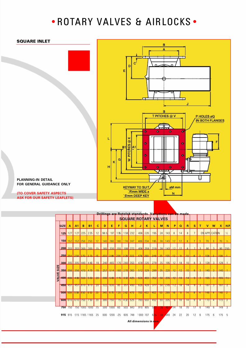
SQUARE ROTARY VALVES
SIZE
125
150
200
250
300
350
400
450
500
600
750
915
All dimensions in mm.
V A L V E S I Z E
A A1 B B1 C D E F G H J K L M N P Q R S T V W X H.P.
152 152 250 250 12 140 280 180 174 247 406 234 195 28 143 12 12 8 7 3 70 3 70 ½
203 203 300 300 15 165 330 155 199 272 406 259 219 28 143 12 12 8 7 3 90 3 90 250
305 305 440 4 40 19 240 465 170 260 353 478 320 279 35 195 12 18 10 8 3 128 3 128 1
254 2 54 370 3 70 15 203 3 88 200 2 29 322 478 290 249 35 155 12 18 10 8 3 108 3 108 1
356 356 470 4 70 19 257 514 160 270 363 512 329 289 35 220 12 12 10 8 3 140 3 140 1
406 4 06 550 5 50 20 300 5 80 1 15 3 32 425 626 403 352 50 235 12 18 14 9 3 165 3 165 1½
457 457 610 610 20 322 630 85 357 450 626 428 377 50 2 85 1 2 18 14 9 3 187 3 187 2
508 5 08 650 6 50 20 340 6 70 120 3 82 475 700 453 402 50 289 16 18 14 9 4 148 4 148 2
610 610 750 7 50 20 380 750 115 4 32 525 700 503 452 50 335 16 18 14 9 4 173 4 173 3
750 750 1000 1000 25 500 1000 60 503 643 910 605 522 70 450 24 18 20 12 6 149 6 149 3
915 915 1165 1165 25 600 1200 -25 605 748 1000 707 625 70 540 24 22 20 12 6 175 6 175 5
127 1 27 225 2 25 12 98.5 197 1 95 1 59 232 406 220 195 28 143 8 14 8 7 ON APPLICATION ½
SQUARE INLET
PLANNING-IN DETAIL
FOR GENERAL GUIDANCE ONLY
(TO COVER SAFETY ASPECTS
ASK FOR OUR SAFETY LEAFLETS)
Drillings are Rotolok standards. Variations can be made.
8/9/2019 Rotary Airlocks
http://slidepdf.com/reader/full/rotary-airlocks 3/17
•ROTARY VALVES & AIR LOCKS•
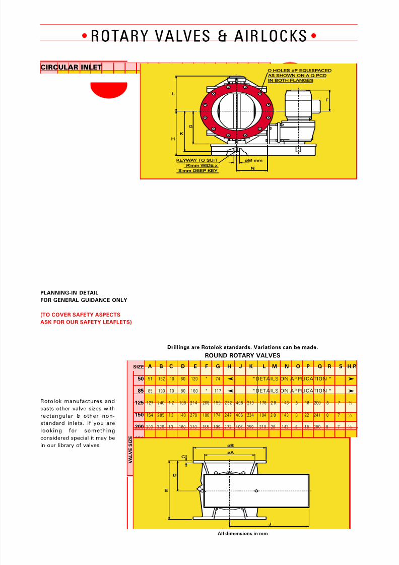
ROUND ROTARY VALVES
SIZE
50
85
125
150
200
250
300
350
400
450
500
600
750
All dimensions in mm
A B C D E F G H J K L M N O P Q R S H.P.
127 2 40 1 2 108 2 14 200 1 59 2 32 406 219 178 2 8 143 8 18 200 8 7 ½
CIRCULAR INLET
154 2 85 1 2 140 2 70 180 1 74 2 47 4 06 234 194 2 8 143 8 22 241 8 7 ½
➤ ➤
➤ ➤
203 3 20 1 3 160 3 10 155 1 99 2 72 4 06 259 219 28 143 8 18 280 8 7 ½
254 3 70 15 200 3 80 200 229 3 22 4 78 289 248 35 155 8 18 320 10 8 1
305 4 40 19 240 4 65 170 2 60 3 53 4 78 320 279 35 195 12 22 395 10 8 1
356 5 33 19 270 5 20 160 2 70 3 63 5 12 332 289 35 220 12 22 445 10 8 1
406 540 20 300 580 110 332 425 626 4 03 352 50 235 12 22 495 14 9 1½
V A L V E S I Z E
457 6 35 20 320 6 25 80 357 4 50 6 26 419 377 50 285 16 32 578 14 9 2
508 7 00 20 340 6 70 115 3 82 4 75 7 00 453 402 50 289 20 32 635 14 9 2
610 8 13 20 385 7 60 115 4 32 5 25 7 00 503 452 50 335 20 35 749 14 9 3
762 984 25 500 1000 45 503 646 910 6 05 522 70 450 28 35 914 20 12 3
PLANNING-IN DETAIL
FOR GENERAL GUIDANCE ONLY
(TO COVER SAFETY ASPECTS
ASK FOR OUR SAFETY LEAFLETS)
Drillings are Rotolok standards. Variations can be made.
Rotolok manufactures and
casts other valve sizes with
rectangular & other non-
standard inlets. If you are
looking for something
considered special it may be
in our library of valves.
85 190 10 80 160 * 117 *DETAILS ON APPLICATION *
51 152 10 60 120 * 74 *DETAILS ON APPLICATION *
8/9/2019 Rotary Airlocks
http://slidepdf.com/reader/full/rotary-airlocks 4/17
•ROTARY VALVES & AIR LOCKS•
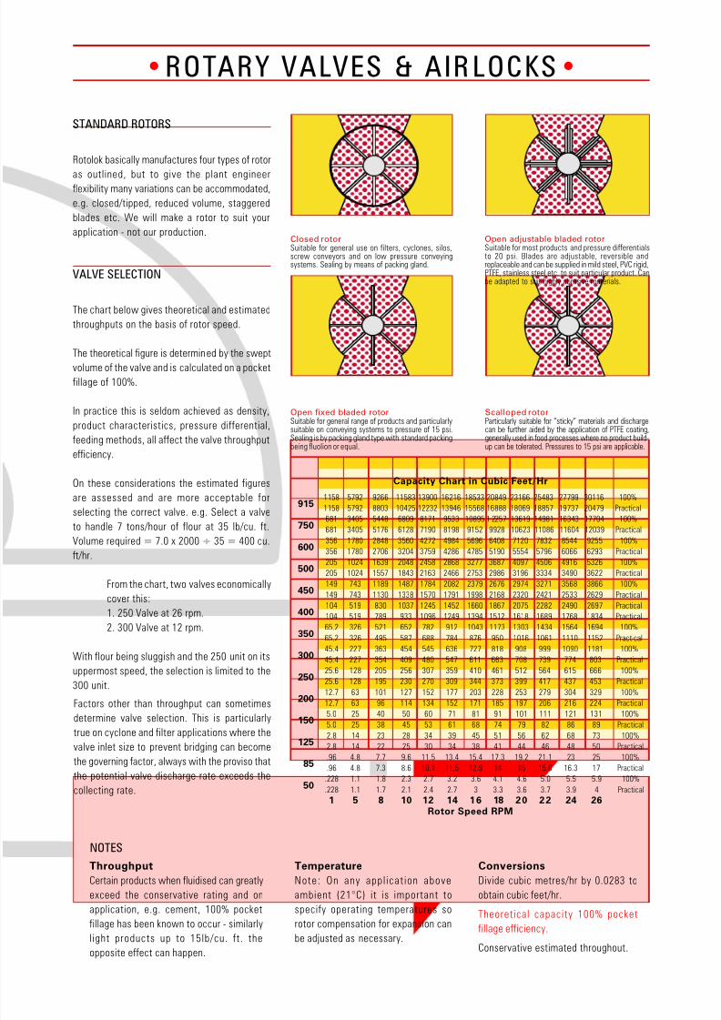
STANDARD ROTORS
Rotolok basically manufactures four types of rotor
as outlined, but to give the plant engineerflexibility many variations can be accommodated,
e.g. closed/tipped, reduced volume, staggered
blades etc. We will make a rotor to suit your
application - not our production.
VALVE SELECTION
Factors other than throughput can sometimes
determine valve selection. This is particularly
true on cyclone and filter applications where the
valve inlet size to prevent bridging can become
the governing factor, always with the proviso that
the potential valve discharge rate exceeds the
collecting rate.
Throughput
Certain products when fluidised can greatly
exceed the conservative rating and onapplication, e.g. cement, 100% pocket
fillage has been known to occur - similarly
l ight products up to 15lb/cu. ft. the
opposite effect can happen.
NOTES
Temperature
Note: On any app l icat ion above
ambient (21°C) it is important tospecify operating temperatures so
rotor compensation for expansion can
be adjusted as necessary.
Conversions
Divide cubic metres/hr by 0.0283 to
obtain cubic feet/hr.
Theoretical capacity 100% pocket
fillage efficiency.
Conservative estimated throughout.
Capacity Chart in Cubic Feet/Hr
1158 5792 9266 11583 13900 16216 18533 20849 23166 25483 27799 30116 100%
1158 5792 8803 10425 12232 13946 15568 16888 18069 18857 19737 20479 Practical
681 3405 5448 6809 8171 9533 10895 1 2257 13619 14981 16343 17704 100%
681 3405 5176 6128 7190 8198 9152 9928 10623 11086 11604 12039 Practical
356 1780 2848 3560 4272 4984 5696 6408 7120 7832 8544 9255 100%
356 1780 2706 3204 3759 4286 4785 5190 5554 5796 6066 6293 Practical
205 1024 1639 2048 2458 2868 3277 3687 4097 4506 4916 5326 100%
205 1024 1557 1843 2163 2466 2753 2986 3196 3334 3490 3622 Practical
149 743 1189 1487 1784 2082 2379 2676 2974 3271 3568 3866 100%
149 743 1130 1338 1570 1791 1998 2168 2320 2421 2533 2629 Practical
104 519 830 1037 1245 1452 1660 1867 2075 2282 2490 2697 Practical
104 519 789 933 1096 1249 1394 1512 1618 1689 1768 1834 Practical
65.2 326 521 652 782 912 1043 1173 1303 1434 1564 1694 100%
65.2 326 495 587 688 784 876 950 1016 1061 1110 1152 Practical
45.4 227 363 454 545 636 727 818 908 999 1090 1181 100%
45.4 227 354 409 480 547 611 663 708 739 774 803 Practical
25.6 128 205 256 307 359 410 461 512 564 615 666 100%
25.6 128 195 230 270 309 344 373 399 417 437 453 Practical
12.7 63 101 127 152 177 203 228 253 279 304 329 100%
12.7 63 96 114 134 152 171 185 197 206 216 224 Practical
5.0 25 40 50 60 71 81 91 101 111 121 131 100%5.0 25 38 45 53 61 68 74 79 82 86 89 Practical
2.8 14 23 28 34 39 45 51 56 62 68 73 100%
2.8 14 22 25 30 34 38 41 44 46 48 50 Practical
.96 4.8 7.7 9.6 11.5 13.4 15.4 17.3 19.2 21.1 23 25 100%
.96 4.8 7.3 8.6 10.1 11.5 12.9 14 15 15.6 16.3 17 Practical
.228 1.1 1.8 2.3 2.7 3.2 3.6 4.1 4.6 5.0 5.5 5.9 100%
.228 1.1 1.7 2.1 2.4 2.7 3 3.3 3.6 3.7 3.9 4 Practical
1 5 8 10 12 14 16 18 20 22 24 26
915
750
600
500
450
400
350
300
250
200
150
125
85
50
Rotor Speed RPM
The chart below gives theoretical and estimated
throughputs on the basis of rotor speed.
The theoretical figure is determined by the sweptvolume of the valve and is calculated on a pocket
fillage of 100%.
In practice this is seldom achieved as density,
product characteristics, pressure differential,
feeding methods, all affect the valve throughput
efficiency.
On these considerations the estimated figures
are assessed and are more acceptable for
selecting the correct valve. e.g. Select a valve
to handle 7 tons/hour of flour at 35 lb/cu. ft.
Volume required = 7.0 x 2000 ÷ 35 = 400 cu.
ft/hr.
From the chart, two valves economically
cover this:
1. 250 Valve at 26 rpm.
2. 300 Valve at 12 rpm.
With flour being sluggish and the 250 unit on its
uppermost speed, the selection is limited to the
300 unit.
Closed rotorSuitable for general use on filters, cyclones, silos,screw conveyors and on low pressure conveyingsystems. Sealing by means of packing gland.
Open fixed bladed rotorSuitable for general range of products and particularlysuitable on conveying systems to pressure of 15 psi.Sealing is by packing gland type with standard packingbeing fluolion or equal.
Open adjustable bladed rotorSuitable for most products and pressure differentialsto 20 psi. Blades are adjustable, reversible andreplaceable and can be supplied in mild steel, PVC rigid,PTFE, stainless steel etc. to suit particular product. Canbe adapted to suit highly abrasive materials.
Scalloped rotorParticularly suitable for “sticky” materials and dischargecan be further aided by the application of PTFE coating,generally used in food processes where no product build-up can be tolerated. Pressures to 15 psi are applicable.
8/9/2019 Rotary Airlocks
http://slidepdf.com/reader/full/rotary-airlocks 5/17
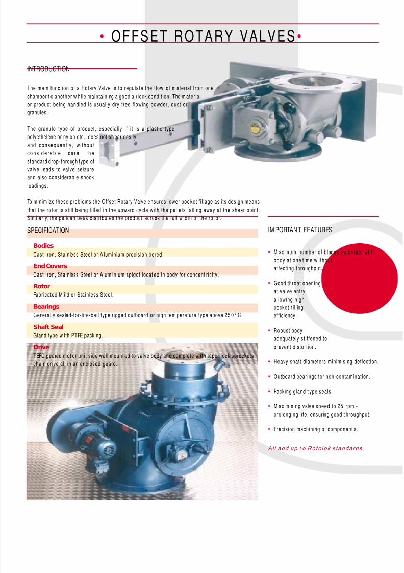
OFFSET ROTARY VALVES •
Bodies
Cast Iron, Stain less Steel or A luminium precision bored.
End Covers
Cast Iron, Stain less Steel or Alum inium spigot locat ed in body for concent r ic i ty.
Rotor
Fabricated M i ld or Stain less Steel .
Bearings
General ly sealed-for- l i fe-bal l type r igged outboard or h igh tem perature t ype above 25 0° C.
Shaft Seal
Gland type w ith PTFE packing.
Drive
TEFC geared mot or uni t s ide wal l mount ed to valve body and complete w i th taper lock sprockets
chain dr ive al l in an enclosed guard.
INTRODUCTION
IM PORTAN T FEATURESSPECIFICATION
The main funct ion of a Rotary Valve is to regulate the f low of m ater ia l from one
chamber t o another w hi le maintain ing a good ai r lock condi t ion. The m ater ia l
or product being handled is usual ly dry free f lowing powder, dust or
granules.
The granule type of product, especia l ly i f i t is a p last ic type,
polyethelene or nylon etc., does not sh ear easily
a n d co n se q u e n t l y , w i t h o u t
c o n s i d e r a b l e c a r e t h e
standard drop-through type of
valve leads to valve seizure
and also considerable shock
loadings.
To minim ize these problems t he Offset Rotary Valve ensures lower poc ket f i l lage as i ts design meansthat the rotor is st i l l being f i l led in the upward cycle wi th the pel lets fa l l ing away at the shear point.
Simi lar ly, the pel ican beak distr ibutes the product across the fu l l w idth of the rot or.
• M aximum number o f b lades incon tac t w i th
body a t one t ime w i thou t
affect ing throughput.
• Good throat opening
at valve entry
al lowing highpocket f i l l ing
efficiency.
• Robust body
adequately st i f fened to
prevent d istort ion.
• Heavy shaft d iameters minimising def lect ion.
• Outboard bear ings for non-contamination.
• Packing gland t ype seals.
• M aximis ing va lve speed to 25 rpm -
prolonging l i fe, ensur ing good t hroughput.
• Precision machining of component s.
Al l add up t o Ro to lok s tandards.
8/9/2019 Rotary Airlocks
http://slidepdf.com/reader/full/rotary-airlocks 6/17
• OFFSET ROTARY VALVES •
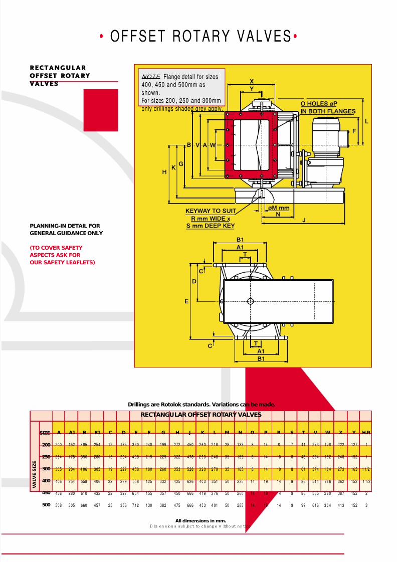
RECTANGULAR OFFSET ROTARY VALVES
All dimensions in mm.D im en sion s sub ject to ch ang e w itho ut no tice
PLANNING-IN DETAIL FOR
GENERAL GUIDANCE ONLY
(TO COVER SAFETY
ASPECTS ASK FOR
OUR SAFETY LEAFLETS)
Drillings are Rotolok standards. Variations can be made.
RECTANGULAR
OFFSET ROTA RY
VALVES
SIZE
200
250
300
400
450
500
V A L V E S I Z E
A A1 B B1 C D E F G H J K L M N O P R S T V W X Y H.P.
200 152 3 05 254 12 165 3 30 240 199 272 450 2 60 2 18 28 133 8 14 8 7 41 273 1 78 222 127 1
254 178 356 280 15 204 4 08 215 229 322 478 2 90 2 48 35 155 8 14 10 8 48 324 152 248 152 1
305 204 4 06 305 19 229 4 58 180 260 353 528 3 20 2 79 35 185 8 14 10 8 61 374 1 84 273 165 1 1/2
406 254 558 406 22 279 558 125 332 425 626 403 351 50 235 14 19 14 9 86 514 266 362 152 1 1/2
458 280 610 432 22 327 6 54 155 357 450 666 419 3 76 50 260 14 19 14 9 86 565 2 80 387 152 2
508 305 660 457 25 356 7 12 130 382 475 666 453 4 01 50 285 14 19 14 9 99 616 3 04 413 152 3
NOTE Flange detail for sizes400, 450 and 500mm asshown.
For sizes 200 , 250 and 300mmonly drillings shaded grey apply.
8/9/2019 Rotary Airlocks
http://slidepdf.com/reader/full/rotary-airlocks 7/17
• OFFSET ROTARY VALVES •
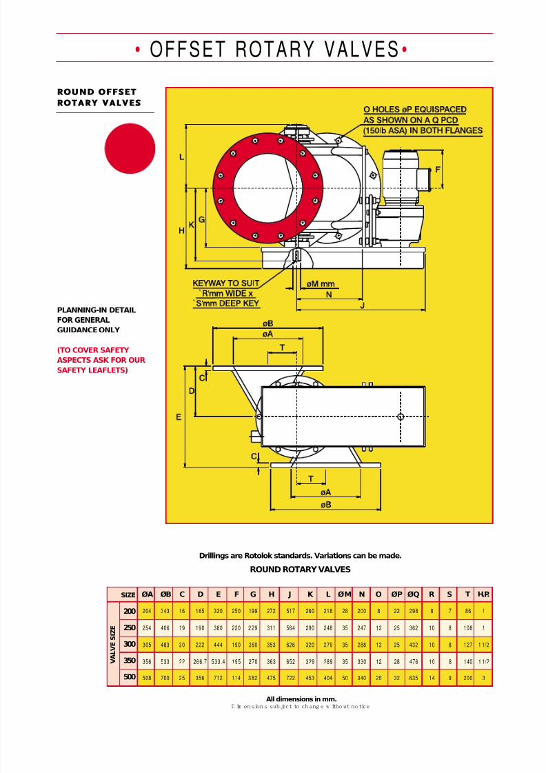
ROUND ROTARY VALVES
All dimensions in mm.D im ension s sub ject to ch ang e w itho ut no tice
ROUND OFFSET
ROTARY VALVES
PLANNING-IN DETAIL
FOR GENERAL
GUIDANCE ONLY
(TO COVER SAFETY
ASPECTS ASK FOR OUR
SAFETY LEAFLETS)
Drillings are Rotolok standards. Variations can be made.
SIZE
200
250
300
350
500
V A L V E S I Z E
ØA ØB C D E F G H J K L ØM N O ØP ØQ R S T H.P.
204 343 16 165 330 250 199 272 517 260 218 28 200 8 22 298 8 7 86 1
254 406 19 190 380 220 2 29 311 564 290 248 35 247 12 25 362 10 8 108 1
305 483 20 222 444 190 260 353 626 320 279 35 288 12 25 432 10 8 127 1 1/2
356 533 22 266.7 533.4 195 270 363 652 329 289 35 330 12 28 476 10 8 140 1 1/2
508 700 25 356 712 114 3 82 475 722 453 404 50 340 20 32 635 14 9 200 3

8/9/2019 Rotary Airlocks
http://slidepdf.com/reader/full/rotary-airlocks 8/17
Body Vent
• OFFSET ROTARY VALVES •
OPTIONS
• B o d y V e n t s
• A i r Pu r g e G l a n d s
• Q u i ck R e l e a se R o to r s
• D i r e c t C o u p l e d D r i v e s
• H a r d C h r o m e I n t e r n a l s
• E le c t r o l e s s N i c k e l P l a t i n g
• S h e a r P la t e D e f l e c t o r s
• S p e e d S w i t c h e s
• D r o p o u t B o x e s
• V.S. Dr i ves
• F l a m e p r o o f M o t o r s
• V e n t B o x e s e t c .
VALVE SELECTION
Facto rs o ther than th roughput can somet imes
dete rmine valve select ion. This is particularly true
on cyclone and f i l ter appl icat ions w here the valve
in le t s i ze to p reven t b r idg ing can become the
governing factor, alw ays wi th t he proviso that t he
p o t e n t i a l v a l v e d i s c h a r g e r a t e e x c e e d s t h e
col lect ing rate.
The chart below gives theoret ical and est imated
throughput s on the basis of rotor speed.
The theoret ical f igure is determined by the sw ept
volume of t he valve and is calculated on a pocket
f i l lage of 100%.
In pract ice th is is seldom achieved as densi ty,
p roduct charac te r i s t i cs , p ressure d i f fe ren t ia l ,
feeding methods, a l l affect the valve throughput
efficiency.
On these considerations the estimated figures are
assessed and are more acceptable for select ing
the correct valve. e.g. Select a valve to handle 7tons/ hour of f lour at 35 lb/ cu. f t . Volume requi red
= 7 .0 x 20 0 0 ÷ 3 5 = 4 0 0 c u. ft / hr.
From the chart , tw o valves econom ical ly
cover th is:
1. 250 Valve at 26 rpm.
2. 300 Valve at 12 rpm.
W ith f lour being sluggish and the 250 uni t on i ts
uppermost speed, the select ion is l imi ted to the
300 un i t .
Throughput
Certain products when f lu id ised can great ly exceed the conservat ive rat ing and on
appl icat ion, e.g. cement, 1 00% pocket f i l lage has been know n to occ ur - s imi lar ly light
p roducts up to 15 lb /cu . f t . the oppos i te e f fec t can happen.
NOTES ON VALVE SELECTION
Temperature
Note: On any appl icat ion above ambient (21°C) i t is important to speci fy operat ing
tem peratures so rotor com pensation for expansion can be adjusted as necessary.
Conversions
Divide cubic metres/hr by 0.0283 to obtain cubic feet/hr.
Air Purge Gland
Capacity Chart in Cubic Feet/Hr
205 1024 1639 2048 2458 2868 3277 3687 4097 4506 4916 5326 100%
205 1024 1557 1843 2163 2466 2753 2986 3196 3334 3490 3622 Pract ical
149 743 1189 1487 1784 2082 2379 2676 2974 3271 3568 3866 100%
149 743 1130 1338 1570 1791 1998 2168 2320 2421 2533 2629 Pract ical
104 519 830 1037 1245 1452 1660 1867 2075 2282 2490 2697 Pract ical
104 519 789 933 1096 1249 1394 1512 1618 1689 1768 1834 Pract ical
65.2 326 521 652 782 912 1043 1173 1303 1434 1564 1694 100%
65.2 326 495 587 688 784 876 950 1016 1061 1110 1152 Pract ical
45.4 227 363 454 545 636 727 818 908 999 1090 1181 100%
45.4 227 354 409 480 547 611 663 708 739 774 803 Pract ical
25.6 128 205 256 307 359 410 461 512 564 615 666 100%
25.6 128 195 230 270 309 344 373 399 417 437 453 Pract ical
12.7 63 101 127 152 177 203 228 253 279 304 329 100%12.7 63 96 114 134 152 171 185 197 206 216 224 Pract ical
500
450
400
350
300
250
200
Rotor Speed RPM
1 5 8 10 12 14 16 18 20 22 24 26

8/9/2019 Rotary Airlocks
http://slidepdf.com/reader/full/rotary-airlocks 9/17
+
“DCV” SERIES ROTARY VALVEINTRODUCTION
Rotolok has been an extremely competitive manufacturer of
Rotary Valves since its formation in 1972.
It has grown considerably over this period world wide.
Having initially introduced a direct coupled Rotary Valve
some 20 years ago with limited success, but with the advent
of many competitors entering this field it is felt that Rotolok
needs to re-focus its attention to the low cost end of the
market.
Rotolok as usual will not see its market eroded and thisleaflet introduces a Dust Valve significantly cheaper than
that of its competitors.
DUST COLLECTOR VALVE •
SPECIFICATION
TRY IT - YOU’LL LIKE ITTRY IT - YOU’LL LIKE ITTRY IT - YOU’LL LIKE ITTRY IT - YOU’LL LIKE ITTRY IT - YOU’LL LIKE IT
ASK FOR OUR SAFETY LEAFLETS
OR SEE OUR WEBSITE
ASK FOR OUR SAFETY LEAFLETS
OR SEE OUR WEBSITE
The general market place cover Cyclones, Bag Houses and Gravity Feed
applications with pressures around _ 3 PSI.
Body Cast Iron Precision Bored
End Covers
Cast Iron Precision Machined and Spigot Located into Valve Body
Rotor
Fabricated Mild Steel Closed (Shrouded) Type Fully Machined
Bearings
Ball Type Rigged Inboard Sealed for Life
Seal
Shaft Seal Rubber Lip Type
Drive
Motorized Worm Box Shaft Mounted on Rotor and Fitted with Standard
I.E.C. Motor TEFC 3PH/50HZ Flange Mounted to Worm Box
Valve Speed
Sizes 150 & 200 - 22 RPM
Sizes 250 & 300 - 25 RPMRotolok Limited, 1 Millennium PlaceTiverton Business Park
Tiverton, Devon EX16 6SB
Tel: 01884 232232 Fax: 01884 232200
e-mail: [email protected] website: www.rotolok.co.uk
Weight
(lbs)Model
cu.ft./hr@
1 rpmHP A B C D E F H O P T U
150
200
250
300
5
12.7
25.6
45.4
1/2
1/2
3/4
3/4
152
203
254
305
250
300
370
440
12
12
18
18
280
330
390
465
296
320
350
388
146
172
204
235
356
356
382
382
12
12
12
12
12
12
12
12
3
3
3
3
70
90
108
128
152
183
256
386
Model
cu.ft./hr@
1 rpmHP A B C D E F H O P Q
150
200
250
300
5
12.7
25.6
45.4
1/2
1/2
3/4
3/4
154
203
254
305
285
320
368
440
12
12
15
19
270
310
380
465
296
320
350
388
146
172
204
235
356
356
382
382
8
8
8
12
18
18
18
18
241
280
320
395
Weight
(lbs)
152
183
256
386
Dimensions are approximate and subject to change without notice.
Planning in detail
All dimensions in mm
Drillings are Rotolok standard
Dimensions are approximate and subject to change without notice.
Planning in detail
All dimensions in mm
Drillings are Rotolok standard
8/9/2019 Rotary Airlocks
http://slidepdf.com/reader/full/rotary-airlocks 10/17
ODDB ALL ROTARY VALVES•
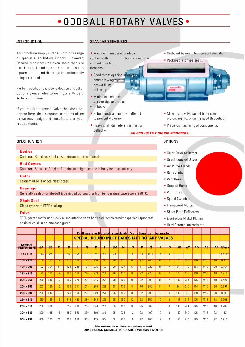
INTRODUCTION
This brochure simply outlines Rotolok’s range
of special sized Rotary Airlocks. However,
Rotolok manufactures even more than are
listed here, including some round inlets to
square outlets and the range is continuously
being extended.
For full specification, rotor selection and other
options please refer to our Rotary Valve &
Airlocks brochure.
If you require a special valve that does not
appear here please contact our sales office
as we may design and manufacture to your
requirements.
STANDARD FEATURES
OPTIONS
• Quick Release Rotors
• Direct Coupled Drives
• Air Purge Glands
• Body Vents
• Vent Boxes
• Dropout Boxes
• V.S. Drives
• Speed Switches
• Flameproof Motors
• Shear Plate Deflectors
• Electroless Nickel Plating
• Hard Chrome Internals etc.
• Maximum number of blades in
contact with body at one time
without affecting
throughput.
• Good throat opening at valve
entry allowing high
pocket filling
efficiency.
• Minimum clearance
at rotor tips and sides
with body.
• Robust body adequately stiffened
to prevent distortion.
• Heavy shaft diameters minimising
deflection.
ØA ØB C D E G K L ØM N O P Q R S AB AC AD AE AF ft3/rev
12.7 89 7 53 106 44 74 55 9.5 - 4 16 60.5 3 3 - - - - - 8.7x10⁻⁵
150 285 12 130 260 198 250 217 28 110 8 22 240 8 7 125 146 100 M10 18 0.11
152 254 8 124 248 174 235 193 28 127 6 11 222 8 7 94 130 104 M10 20 0.167
175 315 12 160 320 220 270 239 28 130 8 22 270 8 7 125 190 100 M10 18 0.218
200 340 12 185 370 255 315 274 28 160 8 22 295 8 7 138 234 125 M12 18 0.423
203 320 12 156 311 219 280 238 28 175 8 10 280 8 7 94 250 104 M10 20 0.394
205 343 19 220 465 260 320 279 35 185 8 22 298 10 8 100 320 140 M16 30 0.75
250 395 15 215 430 280 340 299 35 190 12 22 350 10 8 138 284 125 M12 18 0.705
250 406 15 215 430 280 340 299 35 190 12 25 362 10 8 138 284 125 M12 18 0.705
300 445 16 260 520 330 390 349 35 225 12 22 400 10 8 150 360 125 M12 22 1.33
350 505 21 305 610 365 425 384 50 270 16 22 460 14 9 155 420 125 M12 22 2.216
12.5 x 19
150 x 170
150 x 200
175 x 210
200 x 260
200 x 250
200 x 300
250 x 310
250 x 310
300 x 380
350 x 450
Dimensions in millimetres unless statedDIMENSIONS SUBJECT TO CHANGE WITHOUT NOTICE
SPECIAL ROUND INLET BARESHAFT ROTARY VALVES
Drillings are Rotolok standards. Variations can be made.
• Outboard bearings for non-contamination.
• Packing gland type seals.
• Maximising valve speed to 25 rpm -
prolonging life, ensuring good throughput.
• Precision machining of components.
All add up to Rotolok standards.
Bodies
Cast Iron, Stainless Steel or Aluminium precision bored.
End Covers
Cast Iron, Stainless Steel or Al uminium spigot located in body for concentricity.
Rotor
Fabricated Mild or Stainless Steel.
Bearings
Generally sealed-for-life-ball type rigged outboard or high temperature type above 250° C.
Shaft Seal
Gland type with PTFE packing.
Drive
TEFC geared motor unit side wall mounted to valve body and complete with taper lock sprockets
chain drive all in an enclosed guard.
SPECIFICATION
NOMINALINLETØ x BORE
8/9/2019 Rotary Airlocks
http://slidepdf.com/reader/full/rotary-airlocks 11/17
•ODDB ALL ROTARY VALVES•
80 x 300
100 x 100
100 x 150
230 x 230
125 x 250
125 x 300
200 x 460
200 x 600
230 x 270
350 x 390
300 x 1220
250 x 250
250 x 250
250 x 350
300 x 580
460 x 815
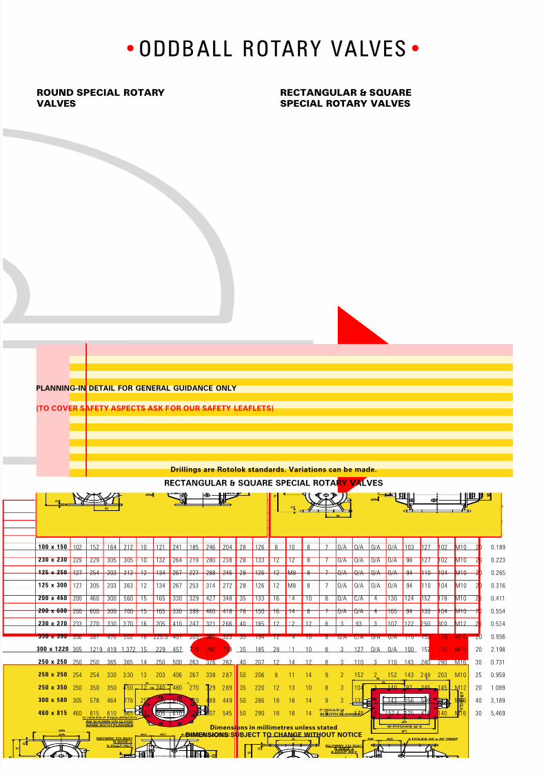
RECTANGULAR & SQUARE SPECIAL ROTARY VALVES
Drillings are Rotolok standards. Variations can be made.
NOMINAL
INLET SIZE
Dimensions in millimetres unless statedDIMENSIONS SUBJECT TO CHANGE WITHOUT NOTICE
A1 B B1 C D E G K L M N P Q R S T V W X AB AC AD AE AF ft3/rev
300 150 330 10 85 1 70 249 310 268 28 - 6 11 8 7 1 114 2 127 - - - - - 0.109
102 171 1 71 1 0 95 190.5 146 1 96 1 65 25 87 4 12 8 7 1 146 1 146 1 01 90 152 M10 20 0.056
152 164 212 10 121 241 185 246 204 28 126 8 10 8 7 O/A O/A O/A O/A 103 127 102 M10 20 0.189
229 305 305 10 132 264 219 280 238 28 133 12 12 8 7 O/A O/A O/A O/A 98 127 102 M10 20 0.223
254 203 312 12 134 267 227 288 246 28 126 12 M8 8 7 O/A O/A O/A O/A 94 110 104 M10 20 0.265
305 203 363 12 134 267 253 314 272 28 126 12 M8 8 7 O/A O/A O/A O/A 94 110 104 M10 20 0.316
460 300 560 15 165 330 329 427 348 35 133 16 14 10 8 O/A O/A 4 130 124 152 178 M10 20 0.411
600 300 700 15 165 330 399 460 418 28 150 16 14 8 7 O/A O/A 4 165 94 130 104 M10 20 0.554
270 330 3 70 16 205 410 247 321 2 66 40 185 12 12 12 8 3 93 3 107 122 2 50 300 M12 20 0.534
387 470 502 16 225.5 451 305 365 323 35 194 12 14 10 8 O/A O/A O/A O/A 110 152 178 M10 20 0.956
1219 419 1,372 15 229 457 719 780 738 35 185 28 11 10 8 3 127 O/A O/A 100 152 178 M10 20 2.198
250 365 365 14 250 500 263 326 282 40 207 12 14 12 8 3 110 3 110 143 240 290 M16 30 0.731
254 330 3 30 13 203 406 267 338 2 87 50 206 8 11 14 9 2 152 2 152 143 2 48 203 M10 25 0.959
350 350 4 50 12 240 480 270 329 2 89 35 220 12 13 10 8 3 104 3 140 97 345 145 M12 20 1.089
578 464 778 25 305 610 429 489 449 50 286 18 18 14 9 3 133 5 143 156 546 330 M16 40 3,189
815 610 965 18 305 610 526 607 545 50 290 18 18 14 9 3 178 6 152.4 125 415 140 M16 30 5,469
ROUND SPECIAL ROTARY
VALVES
RECTANGULAR & SQUARE
SPECIAL ROTARY VALVES
PLANNING-IN DETAIL FOR GENERAL GUIDANCE ONLY
(TO COVER SAFETY ASPECTS ASK FOR OUR SAFETY LEAFLETS)
A
80
102
102
229
127
127
200
200
233
356
305
250
254
250
305
460
8/9/2019 Rotary Airlocks
http://slidepdf.com/reader/full/rotary-airlocks 12/17
B L OW IN G S EA L S •
M aximum number o f b lades in
cont ac t w it h body at one t im e
w i thou t a f fec t i ng
th roughput .
• Streamlined entry and discharge of
conveying ai r through valve.
• Good throat opening at valve entry
al lowing high pocket f i l l ing eff ic iency.
• Compact design minimizing headroom.
• Minimum clearance at rotor t ips and sides
w i th body.
• Robust body adequately st i f fened to prevent
distort ion.
• Heavy shaft d iameters minimizing
deflect ion.
• Outboard bear ings for non-contamination -
opt ion for h igh temperature.
• Packing gland type seals w i th a i r purgingoption.
• Precision machining of component s.
• Abrasive duty types.
STANDARD FEATURES
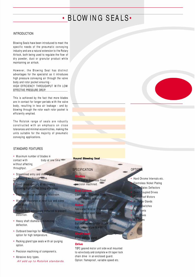
INTRODUCTION
Blowing Sea ls have been in t roduced to meet the
s p e c i f i c n e e d s o f t h e p n e u m a t i c c o n v e y i n g
industry and are a natural extension to t he Rotary
Ai r l ock , bo th be ing used to regu la te the f l ow o f
d r y p o w d e r , d u s t o r g r a n u l a r p r o d u c t w h i l e
maintain ing an ai r lock.
H o w e v e r , t h e B l o w i n g S e a l h a s d i s t i n c t
advan tages fo r the spec ia l i s t as i t i n t roduces
h igh p ressure convey ing a i r th rough the va lve
body and ro to r pocke t ensur ing -
HIGH EFFICIENCY THROUGHPUT W ITH LOW
EFFECTIVE PRESSURE DRO P.
Th is i s ach ieved by the fac t tha t more b ladesare in con tac t fo r l onger per iods w i th the va lve
b o d y , r e su l t i n g i n l e ss a i r l e a ka g e - a n d b y
b lowing th rough the ro to r each ro to r pocke t i s
e f f i c ien t l y empt ied .
T h e R o t o l o k r a n g e o f s e a l s a r e r o b u s t l y
c o n s t r u c t e d w i t h a n e m p h a s i s o n c l o s e
tolerances and minimal eccentr ic i t ies, making the
u n i t s su i t a b l e f o r t h e ma j o r i t y o f p n e u ma t i c
convey ing app l i ca t i ons .
Al l add up t o Ro to lok s tandards.
Bodies
Cast Iron or Stain less Steel
precision machined.
End Covers
Cast Iron or Stain less Steelspigot located in body.
Rotor
Fabricated M i ld or Stain less Steel
f ixed bladed open type.
Bearings
Bal l type seled-for- l ife - a l ternat ive
high tem perature to 4 00° C.
Shaft Seal
PTFE packing gland.
Drive
TEFC geared mot or uni t s ide w al l mounted
to va lve body and comple te w i th taper l ock
chain dr ive in an enclosed guard.
Option: f lameproof, var iable speed etc.
SPECIFICATION
Round Blowing Seal
OPTIONS
• Hard Chrome Internals etc .
• Electroless Nickel Plating
• Shear Plates Deflectors
•Direct Coupled Drives
• Flameproof M otors
• Air Purge Glands
• Speed Swi tches
• Body Vents
• Vent Boxes
• V.S.Drives

8/9/2019 Rotary Airlocks
http://slidepdf.com/reader/full/rotary-airlocks 13/17
• B L OW I N G S EA L S •
RETANGULAR
BLOWING S EAL
PLANNING-IN DETAIL
FOR GENERAL GUIDANCE ONLY
All dimensions in mm.
(TO COVER SAFETY ASPECTS
ASK FOR OUR SAFETY LEAFLETS)
SIZE
125
200
240
280
360
450
V A L V E S I Z E
A A1 B B1 C D E F G H J K L M N
Drillings are Rotolok standards.
Variations can be made.
All dimensions in millimetres
1 25 12 5 2 05 20 5 1 2 11 0 2 40 2 25 15 9 2 52 40 5 2 19 18 0 2 8 95
2 00 20 0 3 00 30 0 1 2 16 0 3 40 1 85 19 9 2 90 40 5 2 58 21 8 2 8 12 5
1 80 20 0 2 80 28 0 1 5 18 0 3 40 2 33 22 5 3 18 43 5 2 86 24 4 4 0 16 5
2 25 27 0 3 45 37 0 1 5 20 6 4 36 2 00 25 9 3 52 46 0 3 20 27 8 4 0 19 0
2 55 35 0 3 50 45 0 1 5 24 0 4 66 1 43 31 5 4 43 59 5 3 86 33 3 5 0 22 7
3 10 40 0 4 10 51 0 1 5 29 0 5 00 1 08 35 0 4 78 62 5 4 21 37 0 5 0 27 0
SIZE
125
200
240
280
360
450
V A L V E
S I Z E
P Q R S T W X Y Z AA AB AC AD AE H.P.
8 1 0 8 7 8 0 90 1 70 9 0 1 70 9 0 1 25 9 5 50 1 1 .5 1 / 2
8 1 3 8 7 1 00 13 0 2 70 130 27 0 130 19 0 1 30 75 11 .5 1 / 2
8 * 12 8 1 10 13 0 2 50 10 0 2 50 1 30 22 5 1 10 65 14 1
8 1 3 1 2 8 1 60 18 0 3 35 1 80 30 7 1 80 30 7 1 70 98 14 1
10 1 4 14 9 2 00 30 0 4 20 18 0 3 20 30 0 32 0 1 80 11 0 14 1 1 / 2
10 1 4 14 9 2 30 32 0 4 80 22 0 3 80 32 0 38 0 2 00 12 5 14 1 1 / 2
8/9/2019 Rotary Airlocks
http://slidepdf.com/reader/full/rotary-airlocks 14/17
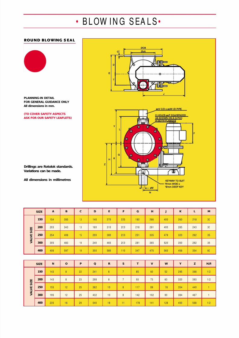
ROUND BLOWING S EAL
PLANNING-IN DETAIL
FOR GENERAL GUIDANCE ONLY
All dimensions in mm.
(TO COVER SAFETY ASPECTS
ASK FOR OUR SAFETY LEAFLETS)
SIZE
150
200
250
300
400
V A L V
E S I Z E
A B C D E F G H J K L M
15 4 28 5 13 14 0 2 70 2 25 1 92 2 66 40 0 26 0 21 8 30
20 3 34 3 13 16 0 3 10 2 00 2 18 2 91 40 0 28 5 24 3 30
25 4 40 6 15 20 0 3 80 2 30 2 51 3 35 47 9 32 0 26 2 35
30 5 48 3 19 24 0 4 65 2 00 2 81 3 65 52 0 35 0 29 2 35
40 6 59 7 19 30 0 5 80 1 10 3 47 4 75 56 5 45 6 35 4 60
Drillings are Rotolok standards.
Variations can be made.
All dimensions in millimetres
• B L OW I N G S EA L S •
SIZE
150
200
250
300
400
V A L V E S I Z E
N O P Q R S T V W Y Z H.P.
14 3 8 22 24 1 8 7 85 60 52 2 95 3 68 1 / 2
14 3 8 23 29 8 8 7 93 73 63 3 20 3 93 1 / 2
15 5 12 25 36 2 10 8 1 17 8 9 78 35 4 44 0 1
19 5 12 25 43 2 10 8 1 42 1 02 9 0 38 4 46 7 1
23 5 1 6 29 54 0 18 11 178 1 41 1 28 4 50 5 68 1 / 2

8/9/2019 Rotary Airlocks
http://slidepdf.com/reader/full/rotary-airlocks 15/17
VALVE SELECTION
Throughput
Certain products w hen fluidised can greatly
e xce e d th e co n se r va t i ve r a t i n g a n d o na p p l i ca t i o n , e .g . ce me n t , 1 0 0 % p o cke t
f i l lage has been know n to occ ur - s imi lar ly
l i g h t p r o d u c t s u p t o 1 5 l b / c u . f t . t h e
opposi te effect can happen.
NOTES
Temperature
N o t e : O n a n y a p p l i c a t i o n a b o v e
a m b i e n t ( 2 1 ° C ) i t i s i m p o r t a n t t osp e c i f y o p e r a t i n g t e mp e r a tu r e s so
rotor compensation for expansion can
be adjusted as necessary.
Conversions
Div ide cub ic metres /h r by 0 .0283 to
obtain cubic feet/hr.
T h e o r e t i c a l c a p a c i t y 1 0 0 % p o c k e t
f i l lage eff ic iency.
Conservat ive est imated throughout.
• B L OW I N G S EA L S•
Capacity Chart in Cubic Feet/Hr
Rotor Speed RPM
V a l v e S i z e
450
400
360
300
280
250
240
200
150
125
120 600 960 12 00 14 40 1 680 1 92 0 2 16 0 2 40 0 264 0 28 80 31 20 10 0%
120 600 920 11 28 13 20 1 510 1 67 0 1 79 0 1 94 4 208 5 22 16 23 40 Prac t ical
104 519 830 10 37 12 45 1 452 1 66 0 1 86 7 2 07 5 228 2 24 90 26 97 10 0%
104 519 789 933 10 96 12 49 1 394 1 51 2 1 61 8 1 68 9 1 76 8 183 4 Prac t ical
6 6 330 528 66 0 79 2 92 4 1 056 1 18 8 1 32 0 1 45 2 158 4 17 16 10 0%
6 6 330 50 7 62 0 72 5 83 0 91 5 98 6 1 06 8 1 14 7 12 18 12 87 Prac t ical
4 5 .4 2 27 3 63 4 54 5 45 6 36 7 27 8 18 9 08 9 99 10 90 11 81 10 0%
45.4 22 7 35 4 40 9 48 0 54 7 6 11 6 63 7 08 7 39 7 74 8 03 Prac t ical
3 2 .5 1 62 2 60 3 25 3 90 4 55 5 20 5 85 6 50 7 15 7 80 8 45 10 0%
32.5 16 2 24 9 30 5 35 5 40 5 4 50 4 85 5 26 5 64 6 00 6 34 Prac t ical
2 5 .6 1 28 2 05 2 56 3 07 3 59 4 10 4 61 5 12 5 64 6 15 6 66 10 0%
25.6 12 8 19 5 23 0 27 0 30 9 3 44 3 73 3 99 4 17 4 37 4 53 Prac t ical
1 7 8 5 136 17 0 20 4 23 8 27 2 30 6 3 40 3 74 4 08 4 42 10 0%
1 7 8 5 13 0 16 0 18 4 21 2 2 35 2 54 2 75 2 96 3 14 3 31 Prac t ical
1 2 .3 62 98 1 23 1 48 1 72 1 97 2 21 2 46 2 71 2 95 320 10 0%
12.3 6 2 9 4 11 6 13 5 15 0 1 71 1 83 1 99 2 14 2 27 2 40 Prac t ical5 .0 25 40 50 60 71 81 91 1 01 1 11 1 21 131 10 0%
5.0 2 5 3 8 45 53 61 68 74 7 9 8 2 8 6 8 9 Prac t ical
2 .7 13 .5 2 5 .5 27 32 .5 3 8 4 3 4 9 5 4 5 9 65 70 1 00 %
2.7 13 .5 20 .5 2 4 2 9 32.5 3 7 4 0 4 2 4 4 4 6 4 8 Prac t ical
1 5 8 10 12 14 16 18 20 22 24 26
The chart below gives theorect ical and pract ical
throughputs on the basis of rotor speed.
The theoret ical eff ic iency is seldom achieved in
p r a c t i se a s d e n s i t y , p r o d u c t ch a r a c te r i s t i c s ,
p ressure d i f fe ren t ia l , feed ing methods e tc . a l l
affect valve throughout.
On these considerat ions the pract ical f igures are
assessed and are more acceptable for correct
valve select ion.
e.g. Select a valve to handle 7½ tonnes/hour of flour
at 34lb/cu. f t .
Vo lume requ ired = 7 .5 x 2200 /34 = 485
cu. ft/ hr.
From t he chart the 280 unit running at 18 rpm covers
this requirement.
Certain products when fluidised can exceed the
conservative ratings. Similarly, light products - 10lb/
cu.ft. the opposite effect can occur.
IF IN DOUBT CONSULT OUR TECHNICAL
DEPARTM ENT.
Retangular Blowing Seal
8/9/2019 Rotary Airlocks
http://slidepdf.com/reader/full/rotary-airlocks 16/17
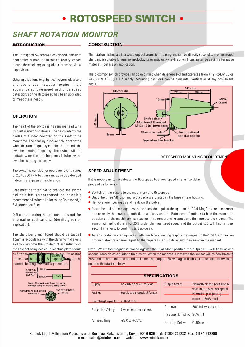
Output State: Normally closed (Volt drop 6
volts max) above set speed.
Normally open (leakage
current 1.6mA max).
Trip Level: 20% below set speed.
Relative Humidity: 90% RH
Start Up Delay: 0-30secs.
SPECIFICATIONS
Supply: 12-240v dc or 24-240v ac.
Fusing: Supply to be fused at 5A max.
Switching Capacity: 200mA max.
Saturation Voltage: 6 volts max (output on).
Ambeint Temp: -25°C to +70°C.
CONSTRUCTION
The total unit is housed in a weatherproof aluminium housing and can be directly coupled to the monitored
shaft and is suitable for running in clockwise or anticlockwise direction. Housing can be cast in alternativematerials, details on application.
The proximity switch provides an open circuit when de-energised and operates from a 12 - 240V DC or
24 - 240V AC 50/60 HZ supply. Mounting positions can be horizontal, vertical or at any convenient
angle.
OPERATION
The heart of the switch is its sensing head with
its built in switching device. The head detects the
blades of a rotor mounted on the shaft to be
monitored. The sensing head switch is activated
when the rotor frequency matches or exceeds the
switches setting frequency. The switch will de-
activate when the rotor frequency falls below the
switches setting frequency.
The switch is suitable for operation over a r ange
of 2.5 to 200 RPM but this range can be extended
if details are given on application.
Care must be taken not to overload the switch
and these details are as charted. In all cases it i s
recommended to install prior to the Rotospeed, a
5 A protection fuse.
Dif ferent sensing heads can be used for
a lternat ive app l icat ions, (detai ls g iven on
application).
The shaft being monitored should be tapped
12mm in accordance with the planning in drawing
and to overcome the problem of eccentricity or
the hole not being coaxial, a locating plate should
be fitted to stop rotation of the switch. By locating
rather than bolting the Rotospeed firmly to the
bracket, bearing overload is prevented.
INTRODUCTION
The Rotospeed Switch was developed initially to
economically monitor Rotolok’s Rotary Valvesaround the clock, replacing labour intensive visual
supervision.
Other applications (e.g. belt conveyors, elevators
and vee dr ives) however require more
sophist icated overspeed and underspeed
detection, so the Rotospeed has been upgraded
to meet these needs.
ROTOSPEED SWITCH •
SHAFT ROTATION MONITOR
ROTOSPEED MOUNTING REQUIREMENT
Rotolok Ltd, 1 Millennium Place, Tiverton Business Park, Tiverton, Devon EX16 6SB Tel: 01884 232232 Fax: 01884 232200
e-mail: [email protected] website: www.rotolok.co.uk
SPEED ADJUSTMENT
If it is necessary to recalibrate the Rotospeed to a new speed or start-up delay,
proceed as follows:-
Switch off the supply to the machinery and Rotospeed. Undo the three M6 caphead socket screws located in the base of rear housing. Remove rear housing by sliding down the cable.
Note: Whilst the magnet is placed against the “Cal Mag” position the output LED will flash at one
second intervals as a guide to time delay. When the magnet is removed the sensor will self calibrate to
20% under the monitored speed and then the output LED will again flash at one second intervals,to
confirm the start up delay.
To recalibrate the start up delay; with machinery running reapply the magnet to the “Cal Mag” Text on
product label for a period equal to the required start up delay and then remove the magnet.
Place the end of the magnet with the black dot against the spot on the “Cal Mag” text on the sensor
and re-apply the power to both the machinery and the Rotospeed. Continue to hold the magnet in
position until the machinery has reached it’s correct running speed and then remove the magnet. The
sensor will self-calibrate for 20% under the monitored speed and the output LED will flash at one
second intervals, to confirm start up delay.
8/9/2019 Rotary Airlocks
http://slidepdf.com/reader/full/rotary-airlocks 17/17
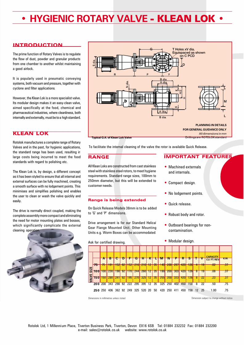
HYGIENIC ROTARY VALVE - KLEAN LOK •
IMPORTANT FEATURES
Machined externals
and internals.
• Compact design.
• No lodgement points.
• Quick release.
• Robust body and rotor.
• Outboard bearings for non-
contamination.
• Modular design.
INTRODUCTION
The prime function of Rotary Valves is to regulate
the flow of dust, powder and granular productsfrom one chamber to another whilst maintaining
a good airlock.
It is popularly used in pneumatic conveying
systems, both vacuum and pressure, together with
cyclone and filter applications.
However, the Klean Lok is a more specialist valve.
Its modular design makes it an easy-clean valve,
aimed specifically at the food, chemical and
pharmaceutical industries, where cleanliness, both
internally and externally, must be to a high standard.
KLEAN LOK
Rotolok manufactures a complete range of Rotary
Valves and in the past, for hygienic applications,
the standard range has been used, resulting in
large costs being incurred to meet the food
standards with regard to polishing etc.
The Klean Lok is, by design, a different concept
as it has been styled to ensure that all internal and
external surfaces can be fully machined, creatinga smooth surface with no lodgement points. This
minimises and simplifies polishing and enables
the user to clean or wash the valve quickly and
easily.
The drive is normally direct coupled, making the
complete assembly more compact and eliminating
the need for motor mounting plates and bosses,
which significantly complicate the external
cleaning operation.
Range is being extended
On Quick Release Models 38mm is to be added
to ‘G’ and ‘P’ dimensions.
Drive arrangement is for our Standard Helical
Gear Flange Mounted Unit. Other Mounting
Units e.g. Worm Boxes can be accommodated.
Ask for certified drawing.
RANGE
All Klean Loks are constructed from cast stainless
steel with stainless steel rotors, to meet hygiene
requirements. Standard range sizes, 100mm to
250mm diameter, but this will be extended tocustomer needs.
Typical G.A. of Klean Lok Valve
To facilitate the internal cleaning of the valve the rotor is available Quick Release.
Rotolok Ltd 1 Millennium Place Tiverton Business Park Tiverton Devon EX16 6SB Tel: 01884 232232 Fax: 01884 232200
Dimensions in millimetres unless stated Dimension subject to change without notice
CAPACITY
CU FT/REV
75
100
150
200
250
V A L V E
S I Z E
A B C D F G H K L M N P R S T V
75 191 152 92 152 216 210 12 35 140 200 297 420 126 4 19 .02 .37
100 230 190 92 170 244 260 12 35 190 200 303 420 126 8 19 .08 .37
150 280 241 92 195 270 325 12 35 255 200 333 420 126 8 22 .23 .37
200 343 298 92 222 295 395 12 35 325 250 402 450 158 8 22 .50 .75
250 406 362 92 249 325 520 20 50 420 250 411 450 158 12 25 1.00 .75
K.W.
T Holes xV dia.Equispaced as shown on C PCD
D
G
M
L
L
PLANNING IN DETAILS
FOR GENERAL GUIDANCE ONLY
All dimensions in mm
Drillings are ROTOLOK standard