rotary clamp cylinder new - rs components
TRANSCRIPT

3 times
Rotary Clamp Cylinder
Series MK
NewNew
Allowable moment of inertia 3 times higher
MK series is released!!New structure! NEWMKNEW
ø12, ø16, ø20, ø25, ø32, ø40, ø50, ø63
Application Example
• Auto switches can be mounted on any of the 4 surfacesto suit the installation conditions (2 surfaces for ø20 and ø25).
• No projection of the auto switch.
ø32 to ø63ø20, ø25
Possible to mount small auto switches on 4 surfaces
A green light indicates the proper
operating range.
Operatingrange OFF
ON
Red Green Red
Proper operating range
2-colour indication solid state auto switchAccurate setting of the mounting position can be performed without mistakes.
MK
MK2
Conventional
Conventional
Workpiece clamp
Rotary stroke
Clamp stroke
Overall length is the same as the existing
products! Mounting dimensions are
interchangeable with the MK series.
Consolidated to the New MK series and renewed!
CAT.EUS20-214A-UK

Standard stroke range has been expanded.
Strokes have been added to the New MK series, making a wide
range of strokes available. ( indicates the added strokes.)
Series Bore sizeStroke
MK
12
16
20
25
32
40
50
63
10 20 30 50
Head flanges are newly
available for ø12 and ø16.
Mounting type has been added to suit a
wide range of applications.
Applicable to
the D-P3DW type
2 types of cylinder mounting are available with one body.
2 types of cylinder mounting, through-hole mounting
and tap mounting, are available for mounting the cylinder.∗ For the tap mounting, the thread length is different from the existing product.
Series MK
Maintenance can be performed for all sizes.
Clamping rotary direction can
be selected from 2 types.
Clamping rotary direction can be selected to suit the
setting conditions.
Allowable moment of inertia 3 times higher
Allowable moment of inertia is the same as the heavy-duty MK2 series.
10-4
10-3
10-2
10-1
50 100 200
Piston speed [mm/s]
Allo
wable
mom
ent of in
ert
ia [kg
·m2]
Standard arm
3 to 10 mm shorter than the MK2 series, making
the product more compact.
Overall length is shortened.(equivalent to the MK series)
Overall length comparison
Overall Length Dimensions
Mounting examples
Bore sizeShortened dimensions
(compared to theconventional MK2 series)
20
25
32
40
50
63
3 mm
5 mm
8 mm
8 mm
10 mm
10 mm
112.5
113.5
133.5
134.5
152
155
New MK series(Standard)
Conventional MK2 series(Heavy-duty type)
Conventional
MK series
Overall length is shortened.
Seal kit and guide pin are replaceable.
Guide pin
NEW
MK seriesoverall length (at 20st)
NEW
NEW
Allowable Moment of Inertia (ø32, ø40)
Through-hole
Tapped
NewMK
series
Conventional MK
series
ConventionalMK2series
Rightrotation
type
Leftrotation
type
Flange
Magnetic field resistant auto switch can be used.
Features 1

Rotary angle Rotary angle
During unclamping
(Extension end)
L type
(Counterclockwise)
During unclamping
(Extension end)
R type
(Clockwise)
During clamping (Retraction end)
Non-rotating accuracy
Port side
Note) Maximum piston speed indicates the maximum speed possible
when employing a standard arm.
SeriesItem
Max. piston speed Note) [mm/s] 200
±1.4°
±1.2°
±0.9°
±0.7°
90°±10°
Not allowed
ø12 to ø63
ø12
ø16 to ø25
ø32, ø40
ø50, ø63
New MK
Designing Arms
1. Allowable bending momentUse the arm length and operating pressure within Graph (1) for allowable bending moment loaded piston rod.
2. Moment of inertiaWhen the arm is long and heavy, damage of internal parts may be caused due to inertia. Use the moment of inertia and cylinder speed within Graph (2) based on arm requirements.
Note) Use ø63 within a pressure range from 0.1 to 0.6 MPa.If ø63 is used within a pressure range from 0.61 to 1 MPa, please use –X2071.
When arms are to be made separately, their length and mass should be within the following range.
500 100
82 150200
Mom
ent
of
inert
ia [
kg·m
2]
Maximum piston speed Note) [mm/s]
2
4610–1
2
4610–2
2
4610–3
2
4610–4
2
4610–5
New MK20, 25
New MK50, 63
New MK32, 40
New MK12, 16
Operating range
Graph (1) Graph (2)
Arm
length
[m
m]
Operating pressure [MPa]
200
100
80
60
40
20
0.1 0.2 0.4 0.6
0.45 0.551
New MK12
New MK16
New MK20, 25
New MK32, 40
New MK50, 63 Note)
Operating range
Series MK
Model Selection
Non-rotating accuracy
(Clamp part)
Rotary angle
Horizontal mounting
• When the arm length is 80 mm, pressure should beNew MK20/25: 0.45 MPa or less,New MK32/40: 0.55 MPa or less.
• When the arm’s moment of inertia is 1 x 10⁻³ kg·m2, cylinder speed should beNew MK20/25: 82 mm/s or less,New MK32/40: 150 mm/s or less.
• For calculating the moment of inertia, refer to page 3.
Note) Maximum piston speed is equivalent to approximately 1.6x the average piston speed. (Rough indication)
Caution
1

Maximum piston speed [mm/s]
Allo
wable
mo
me
nt o
f in
ert
ia [kg
·m2]
ø20, ø25
New MK
ø20, ø25 Standard arm single unit
Maximum piston speed [mm/s]
Allo
wable
mom
ent of in
ert
ia [kg
·m2]
ø50, ø63
New MK
ø50, ø63 Standard arm single unit
ø32, ø40
Maximum piston speed [mm/s]
Allo
wable
mom
ent of in
ert
ia [kg
·m2]
New MK
ø32, ø40 Standard arm single unit
Note) Maximum piston speed is equivalent to approximately 1.6x the average piston speed. (Rough indication)
ø12, ø16
Maximum piston speed [mm/s]
Allo
wable
mo
me
nt o
f in
ert
ia [kg
·m2]
10–5
10–4
10–3
10–2
10–1
50 100 200
10–4
10–3
10–2
10–1
50 100 20010–4
10–3
10–2
10–1
50 100 200
10–6
10–5
10–4
10–3
50 100 200
ø12 Standard arm single unit
ø16 Standard arm single unit
New MK
Calculate the operating conditions and operate this product within the allowable range.
If the allowable range is exceeded, increase the bore size or use the MK2T series.
(Refer to SMC Best Pneumatics No. 3 for details of the MK2T series.)
(MK2T)
(MK2T)
(MK2T)
Moment of Inertia
Bore Size Selection
2

Ι: Moment of inertia [kg·m2] m: Load mass [kg]
If arms other than the options are used, be sure to calculate the moment of inertia of the arm before selecting it.
1.0 x 10⁻¹
1.0 x 10⁻²
1.0 x 10⁻³
1.7 x 10⁻³
1.0 x 10⁻⁴
10 100
New MK
115200
ø32, ø40
Maximum piston speed [mm/s]
Allo
wa
ble
mo
me
nt o
f in
ert
ia [kg
·m2]
1000
Calculation example when arms other than the options are used.
Calculation result (when the bore size is ø32 and clamp stroke is 10 mm.)
Model
New MK
Max. piston speed Average piston speed Note 1) Total stroke Note 2) Stroke time Note 3)
Note 1) Average piston speed = Max. piston speed 1.6 Note 2) Total stroke = Clamp stroke + Rotary stroke Note 3) Total stroke Average piston speed
The stroke time should be longer than the above mentioned stroke time.
115 mm/s 72 mm/s 25 mm 0.35 seconds
Ι (Moment of inertia)
• Calculate the actual moment of inertia.
Ι = Ι1 + Ι2 = (8.2 + 8.7) x 10–4 = 1.7 x 10⁻³ kg•m2
Note) Maximum piston speed is equivalent to approximately 1.6x the average piston speed. (Rough indication)Moment of Inertia
Ι = m1· + m2·a12
3
a22
3
1. Thin shaftPosition of rotational axis: Perpendicular to the shaft, and attached near one end
Ι = m·a2
12
2. Thin shaftPosition of rotational axis: Perpendicular to the shaft, and attached at the centre of gravity
Ι = m·a2
12
3. Thin rectangular plate (Rectangular parallelopiped)Position of rotational axis: Parallel to side b, and attached at the centre of gravity
Ι = m1· + m2· 4a12 + b2
12
4a22 + b2
12
4. Thin rectangular plate (Rectangular parallelopiped)Position of rotational axis: Perpendicular to the plate, and attached near one end
Ι = m·a2 + b2
12
5. Thin rectangular plate (Rectangular parallelopiped)Position of rotational axis: Attached at the centre of gravity, and perpendicular to the plate (Same as also thick rectangular plate)
a
Ι = m1· + m2·a22 + ka12
3
k = m2·2r2
5
6. Load at the end of lever arm
Calculation Equation List for Moment of Inertia
øD
Arm: Ι1
Arm mass: m1
Clamping jig: Ι2
Clamping jig mass: m2
AB
L
S• Calculate the moment of inertia of the arm.
Ι1 = m1• ———— + m1• — – S 2A2 + B2
12A2
Ι2 = m2• —— + m2•L2D2
8
• Calculate the moment of inertia of the clamping jig.
Ι1 = 0.35 x ————— + 0.35 x —— – 0.012 2
=
8.2 x 10⁻⁴ kg•m20.12 + 0.032
120.12
Ι2 = 0.15 x ——— + 0.15 x 0.0762 = 8.7 x 10⁻⁴ kg•m20.022
8
<Calculation example> when the cylinder
bore size is ø32.
A = 0.1 m D = 0.02 m
B = 0.03 m m1 = 0.35 kg
S = 0.012 m m2 = 0.15 kg
L = 0.076 m
Bore Size Selection
3

4

MK 10Rotary clamp cylinder
Auto switch type
R20B
—
S
2 pcs.
1 pc.
N Z
Auto switch type
∗ For applicable auto switch models, refer to the below table.
∗ Auto switches are shipped together, (but not assembled).
—Without auto switch
(Built-in magnet)
Body option
Auto switch multipleside mounting
—
N
Standard (Female thread)
With arm
Rotary direction(Unclamp � Clamp)
Clockwise
CounterclockwiseR
L
Bore size
12
16
20
25
32
40
50
63
12 mm
16 mm
20 mm
25 mm
32 mm
40 mm
50 mm
63 mm Clamp stroke
∗ Arms are shipped together, (but not assembled).
Mounting bracket
Through-hole/Both endstapped common (Basic)Head flange
Symbol
B
G
∗ Head flanges are shipped together, (but not assembled).
M9BW
M thread
Rc
NPT
G
ø12 to ø25
ø32 to ø63
Port thread type
—
TN
TF
Made to Order(Refer to the next page for details.)
Applicable bore size
ø12 to ø63
ø32 to ø63
Clamp stroke
10 mm
20 mm
30 mm
50 mm
Symbol
10
20
30
50
During unclamping(Extension end)L type(Counterclockwise)
During unclamping(Extension end)
R type(Clockwise)
During clamping (Retraction end)
Port side
Rotary Clamp Cylinder: Standard
ø12, ø16, ø20, ø25, ø32, ø40, ø50, ø63Series MK
How to Order
Re
ed
sw
itch
So
lid
sta
te s
wit
ch
Indica
tor lig
ht
IC circuit
IC circuit
IC circuit
IC circuit
IC circuit
∗ Lead wire length symbols: 0.5 m ·········· — (Example) M9NW 1 m ·········· M (Example) M9NWM 3 m ·········· L (Example) M9NWL 5 m ·········· Z (Example) M9NWZ
∗ Solid state auto switches marked with “�” are produced upon receipt of order. ∗ For D-P3DW�, ø32 to ø63 are available.
∗ Since there are other applicable auto switches than listed, refer to page 15 for details.∗ For details about auto switches with pre-wired connector, refer to Best Pneumatics No. 3.
For D-P3DW�, refer to the catalogue ES20-201.∗ Auto switches are shipped together, (but not assembled).∗ The coil scraper is not built-in.
Magnetic field resistant(2-colour indication)
Mounting
YesGrommet
3-wire (NPN)
3-wire (PNP)
2-wire
3-wire (NPN)
3-wire (PNP)
2-wire
3-wire (NPN)
3-wire (PNP)
2-wire
2-wire (Non-polar)
24 V
5 V,
12 V
12 V
5 V,
12 V
12 V
5 V,
12 V
12 V
—
Relay,PLC
—Diagnostic indication(2-colour indication)
Water resistant(2-colour indication)
—
Type Special function Electricalentry
Wiring(Output)
Load voltage
DC AC
Lead wire length (m)
0.5(—)
1(M)
3(L)
5(Z)
None(N)
Applicableload
Pre-wiredconnector
Auto switch model
Perpendicular In-line
No
YesGrommet
—
100 V
100 V or less
3-wire (NPN equivalent)
2-wire 24 V
5 V
12 V
5 V,12 V
——
—
Relay,PLC
—
—
—
—
—
—
—
—
—
—
A96V
A93V
A90V
A96
A93
A90
�������������
���������
�������������
����������
—
—
—
—
—
—
—
—
—
—
—
—
—
—
—
—
—
����������
M9NV
M9PV
M9BV
M9NWV
M9PWV
M9BWV
M9NAV
M9PAV
M9BAV
—
M9N
M9P
M9B
M9NW
M9PW
M9BW
M9NA
M9PA
M9BA
P3DW∗
Applicable Auto Switches/Refer to Best Pneumatics No. 3 for further information on auto switches. For D-P3DW, refer to the catalogue ES20-201.
∗ The coil scraper is not built-in.
5

During unclamping(Extension end)80° to 100°(90° ± 10°)L type(Counterclockwise)
During unclamping(Extension end)
80° to 100°(90° ± 10°)
R type(Clockwise)
Clamp part
During clamping (Retraction end)
Non-rotating accuracy±0.7° to 1.4°
Port side
Made to Order(For details, refer to page 18)
Bore size (mm) Part no. Accessories
Clamp bolt,Hexagon sockethead cap screw,Hexagon nut,Spring washer
Note) Theoretical output (N) = Pressure (MPa) x Piston area (cm2) x 100Operating direction IN: Clamp OUT: Unclamp
Bore size(mm)
12
16
20
25
32
40
50
63
Rod size(mm)
Operatingdirection
6
8
12
12
16
16
20
20
INOUTIN
OUTIN
OUTIN
OUTIN
OUTIN
OUTIN
OUTIN
OUT
Piston area(cm2) 0.8 1.1 1.5 2.0 2.0 3.1 3.8 4.9 6.0 8.010.612.616.519.628.031.2
0.3 25 34 45 60 60 94113147181241317377495589841935
0.5 42 57 75 101 101 157 189 245 302 402 528 628 825 98214021559
0.7 59 79 106 141 141 220 264 344 422 563 739 88011551374
——
1.0 85 113 151 201 201 314 378 491 603 8041056125716491963
——
Operating pressure (MPa)Unit: N
Clamp stroke(mm)10203050
Bore size (mm)Unit: g
12698499—
16 94113132—
20222250279—
25282319355—
32445494542639
40517570623728
50 921100110811241
631256136414721687
Bore size (mm) Part no. Accessories
Hexagon sockethead cap screw
Unit: gBore size (mm)
With armHead flange(including mounting bolt)
121358
163269
20100130
25100150
32200175
40200209
50350371
63350578
Note 1) Refer to Rotary Angle figure.Note 2) Direction of rotation viewed from the rod end when the piston rod is retractingNote 3) Clamp force at 0.5 MPaNote 4) When using the cylinder within a pressure range from 0.61 to 1 MPa, please use –X2071. Note 5) Be sure to install a speed controller to the cylinder, and adjust the cylinder speed to make it within the
range from 50 to 200 mm/s. To adjust the speed, start with the needle in the completely closed position, and then adjust it by opening gradually.
MK-A012ZMK-A016Z
MK-A020Z
MK-A032Z
MK-A050Z
12
16
20
25
32
40
50
63
1216202532405063
CQS-F012CQS-F016MKZ-F020MKZ-F025
MK2T-F032MK2T-F040MK2T-F050MK2T-F063
ActionRotary angle Note 1)
Rotary direction Note 2)
Rotary stroke (mm)Clamp stroke (mm)Theoretical clamp force (N) Note 3)
FluidProof pressure
Operating pressure range
Ambient and fluid temperature
Lubrication
Piping port size
Bore size (mm)Double acting
90° ±10Clockwise, Counterclockwise
Air1.5 MPa
0.1 to 1 MPa
Without auto switch: –10 to 70 °C (No freezing)With auto switch: –10 to 60 °C (No freezing)
Non-lube
Rubber bumper
50 to 200 mm/s
12 16 20 25 32 40 50
7.5 9.5 15 1910, 20, 30 10, 20, 30, 50
63
40 75 100 185 300
Through-hole/Both ends tapped common, Head flange
525 825
±1.4 ±1.2 ±0.9 ±0.7
M5 x 0.8
1400
+0.6–0.4
0.1 to 0.6 MPa
Rc1/8, NPT1/8 G1/8
Rc1/4, NPT1/4 G1/4
Note 4)
MountingCushion
Stroke length tolerance
Piston speed Note 5)
Non-rotating accuracy (Clamp part) Note 1)
Specifications
Rotary Angle
Option/Arm
Mounting Bracket/Flange
Theoretical Output
Weight
Additional Weight
• Standard calculation: MKB20-10RZ• Extra weight calculation: Head flange With arm
...........222 g.............130 g
..................100 g452 g
Calculation: (Example) MKG20-10RNZ
-X2071-X2094-X2172
-X2177
-X2997
Max. operating pressure 1.0 MPa
Overall length is the same as the MK2 series
With boss in head end
Symbol Description
The dimension of head end flange is the same as the current series MK and MK2.
Rotary angle 60° specifications
-XB6Heat resistant cylinder (-10 to 150 °C)w/o auto switch only Note 1)
-XC4-XC22
With heavy duty scraper Note 2)
Fluororubber seals Note 3)
Note 1) Except ø12 and ø16.
Note 2) Except ø12.
Note 3) The bumper is a standard product.
Series MK
6

Fig. 1
Spanner
Hexagon wrench key
Arm
Mounting bolt
Flat washer CD
Clamp Arm Mounting
Use a clamp arm that is available as an option.
To fabricate a clamp arm, make sure that the allowable bending moment and the inertial moment will be within the specified range.Refer to Graph 1 and 2 on page 1.
If one side of the piston is pressurized by supplying air with the clamp arm attached, the piston will move vertically while the clamp arm rotates.
This operation could be hazardous to personnel, as their hands or feet could get caught by the clamp arm, or could lead to equip-ment damage. Therefore, it is important to secure as a danger zone a cylindrical area with the length of the clamp arm as its ra-dius, and the stroke plus 20 mm as its height.
Ensuring Safety
Clamp Arm Mounting and Removal
When the arm is mounted onto or removed from the piston rod, do not fix the cylinder body, but hold the arm with a spanner when tightening or loosening the bolt (Fig. 1).
If the bolt is tightened with the cylinder body fixed, excessive ro-tation force will be applied to the piston rod, which may damage the internal components.Note that when making an arm, machine it so that it engages with the width across flats on the rod end to prevent it from rotating.
Note) Be sure to use a flat washer to mount cylinders via through-holes.
Head Flange Mounting
The mounting bolt for the head flange should be tigh-tened to the torque shown in the below table.
Cylinder model
8
8
9
8
9.5
11
10.5
14.1
50
60
70
50
60
70
75
85
95
75
85
95
85
95
105
125
80
90
100
120
90
100
110
130
95
105
115
135
M3 x 50L
M3 x 60L
M3 x 70L
M3 x 50L
M3 x 60L
M3 x 70L
M5 x 75L
M5 x 85L
M5 x 95L
M5 x 75L
M5 x 85L
M5 x 95L
M5 x 85L
M5 x 95L
M5 x 105L
M5 x 125L
M5 x 80L
M5 x 90L
M5 x 100L
M5 x 120L
M6 x 90L
M6 x 100L
M6 x 110L
M6 x 130L
M8 x 95L
M8 x 105L
M8 x 115L
M8 x 135L
MKB12-10�Z
-20�Z
-30�Z
MKB16-10�Z
-20�Z
-30�Z
MKB20-10�Z
-20�Z
-30�Z
MKB25-10�Z
-20�Z
-30�Z
MKB32-10�Z
-20�Z
-30�Z
-50�Z
MKB40-10�Z
-20�Z
-30�Z
-50�Z
MKB50-10�Z
-20�Z
-30�Z
-50�Z
MKB63-10�Z
-20�Z
-30�Z
-50�Z
C D Mounting bolt size
Mounting Bolt for MKB-Z
12
16
20, 25
32, 40
50, 63
0.5 to 0.7
2.8 to 3.5
11.5 to 14.0
24 to 30
75 to 90
Bore size(mm)
Proper tighteningtorque (N·m)
ø12, 16
ø20 to 40
ø50
ø63
M4 x 0.7
M6 x 1.0
M8 x 1.25
M10 x 1.5
1.4 to 2.6 N·m
9.0 to 12.0 N·m
11.4 to 22.4 N·m
25.0 to 44.9 N·m
Bore size Thread size Tightening torque
Proper Tightening Torque
Mounting: Mounting bolt for through-hole type is available.Ordering: Add the word “Bolt” to the mounting bolt size.
Example) Bolt M5 x 75 L (4 pcs.)
Rotary Clamp Cylinder: Standard Series MK
Caution
Caution
Caution
Caution
7

MK�32-�Z
Replacement Parts/Seal Kitø12
CQSB12-PSø16
CQSB16-PSø20
MK20Z-PSø25
MK25Z-PSø32
MK32Z-PSø40
MK2T40-PSø50
MK2T50-PSø63
MK63Z-PSBore size (mm)
Kit no.Contents
Replacement Parts/Guide Pin Kitø12
MK12Z-GSø16
MK16Z-GSø20
MK20Z-GSø25
MK25Z-GSø32
MK32Z-GSø40
MK40Z-GSø50
MK50Z-GSø63
MK63Z-GSBore size (mm)
Kit no.Contents
∗ Guide pin kit includes numbers in the table. Order the guide pin kit, based on each bore size.
No.1
2
3
4
5
6
7
8
9
10
11
12
13
14
15
16
17
DescriptionAluminum alloyAluminum alloyAluminum alloyAluminum alloyStainless steelCarbon steel
Copper bearing materialStainless steel
Carbon tool steelCarbon tool steel
Chromium molybdenum steelStainless steel
NBRCarbon tool steelPhosphor bronze
Stainless steelRolled steel
Carbon tool steel
Hard anodisedHard anodised
ChromatedChromated
ø12 to ø25 Nitridingø32 to ø63 Heated, Nickel plated
ø32 to ø63 onlyø20 to ø32 onlyø12, ø16 only
ø40 to ø63 onlySharp end section: 90
Nitriding
Except ø12, ø16Except ø12, ø16Except ø12, ø16
Electroless nickel platedø20 to ø32 only
Component Parts
Cylinder tube
Rod cover
Piston
Magnet holder
Piston rod
Bushing
Stop ring
Round R-type retaining ring
C-type retaining ring
Hexagon socket head set screw
Guide pin
O-ring
Round R-type retaining ring
Coil scraper
Scraper pressure
Head cover
C-type retaining ring
No.18
19
20
21
22
23
24
25
26
27
28
29
30
31
32
Description MaterialUrethaneUrethane
—ResinNBRNBRNBRNBR
Rolled steelChromium molybdenum steel
Hard steelChromium molybdenum steel
Rolled steelRolled steel
Note
ø12, ø16 only
Except ø12, ø16
ø20 to ø32 only
Component Parts
Qty.
Bumper
Bumper B
Magnet
Wear ring
Rod seal
Piston seal
Gasket
O-ring
Arm
Hexagon socket head cap screw
Spring washer
Clamp bolt
Hexagon nut
Flange
Hexagon socket head cap screw
ø12, ø16, ø32 to ø40: 4 pcs.ø20, ø25: 2 pcs.
New MK12, 16
New MK20 to 32
New MK40 to 63
With arm (N)
Head flange (G)
∗ For the replacement procedure of the replacement parts/seal and guide pin kits, refer to the Operation Manual.
Material Note
Construction
Set of nos. above Set of nos. above
Set of nos. above
∗ Seal kit includes numbers in the table. Order the seal kit, based on each bore size.∗ Since the seal kit does not include a grease pack, order it separately. Grease pack part no.: GR-S-010 (10 g)
Chromiummolybdenum steel
#1#2Rod flange (F)
Series MK
8

V
During clamping(Retraction end)
Rotary direction: LDuring unclamping(Extension end)
Rotary direction: RDuring unclamping(Extension end)
Port side
U
N
8 to 18
IPO
M
Flat washerWith 4 pcs.
M4 x 0.7 (4 locations)
M5 x 0.8 (2 locations)(Port size)
(The dimension on the oppositeside is the same.)
(The d
imen
sion o
n the
oppo
site
side i
s the
same
.) 0.5
R
Q
øH (R
od s
ize)
ø Yh
9
2.5
3
47 ø3
.5 (4
loca
tions
)
7
4
ø6.5
(4 lo
catio
ns)
15 5.5
2
5.5
ø4.5 (2 locations) M4 x 0.7 (4 locations)(Special cap bolt)
FV
FZ
FX
ø12
E effective thread depth F
Auto switchMinimum bending radiusof lead wire 10 �A
�C
�D
øB
Through-hole/Both ends tapped common
(Basic)
Head flange
With arm
Dimensions: ø12, ø16
A B C D E F øYh9H2529
3238
15.520
57
M3 x 0.5M5 x 0.8
5.56.5
68
MKB12-ZMKB16-Z
Model1114
0–0.043 0–0.043
(mm)
Note) The above figure is with the auto switch (D-M9�) mounted.
The outline dimensions shown are when the rod is retracted.
Rodstate
RetractedExtendedRetractedExtended
10 mmClamp stroke
Q R68 85.568 85.5
45.5
45.5
20 mmQ R88
115.588
115.5
55.5
55.5
30 mmQ R
108 145.5108 145.5
65.5
65.5
MKB12-Z
MKB16-Z
Model
(mm)
I N O P U V45
811
2936
2025
811
M3 x 0.5M4 x 0.7
MKB12-ZMKB16-Z
Model(mm)
FV FX FZ2530
4545
5555
MKG12-ZMKG16-Z
Model(mm)
RetractedExtendedRetractedExtended
10 mmClamp stroke
M
28.546 31.549
38.566 41.569
48.586 51.589
20 mm 30 mm
MKB12-Z
MKB16-Z
Model Rodstate
Basic
With Arm
Head Flange
Arm
MM
M
Rod flange
M
23
40.5
26
43.5
Retracted
Extended
Retracted
Extended
33
60.5
36
63.5
43
80.5
46
83.5
MKF12-Z
MKF16-Z
ModelRod
state10 mm
Clamp stroke
20 mm 30 mm
MM
17
34.5
17
34.5
27
54.5
27
54.5
37
74.5
37
74.5
10 mm
Clamp stroke
20 mm 30 mm
(mm)Rod Flange
∗ The dimensions other than MM dimensions are the same as those of head flange.
∗ The arm dimensions other than M dimensions are the same as those of with arm.
Rotary Clamp Cylinder: Standard Series MK
9

M6 x 1 (2 locations)Flat washerWith 2 pcs.
M5 x 0.8 (2 locations)(Port size)
(The dimension on the oppositeside is the same.)
(The d
imen
sion o
n the
oppo
site
side i
s the
same
.)
7 10 710
ø5.5
(2 lo
catio
ns)
ø9 (2
loca
tions
)
ø12
(Rod
siz
e)ø G
1
34 3
S T
R
Q
øYh
9
8
35
M
51
7
14
12 to 22
ø6.6 (2 locations) M6 x 1.0 (2 locations)(Special cap bolt)
FV
FZ
FX
M8 x 1.25Effective thread depth 11
Auto switchMinimum bending radiusof lead wire 10
�A
�10
C
B
13.6
6.8
F
E
M6 x 1.016During clamping(Retraction end)
Rotary direction: LDuring unclamping(Extension end)
Rotary direction: RDuring unclamping(Extension end)
Port side
Through-hole/Both ends tapped common
(Basic)
Head flange
With arm
Dimensions: ø20, ø25 The outline dimensions shown are when the rod is retracted.
A B C E F G3640
4752
3640
35.540.5
1821
17.922.5
S28 27.5
T 9 10.5
MKB20-ZMKB25-Z
Model øYh91823
0–0.043 0–0.052
(mm)
Note) The above figure is with the auto switch (D-M9�) mounted.
RetractedExtendedRetractedExtended
10 mmClamp stroke
Q R 92.5112 93.5113
72
73
20 mmQ R
112.5142 113.5143
82
83
30 mmQ R
132.5172 133.5173
92
93
MKB20-Z
MKB25-Z
Model Rodstate
(mm)
RetractedExtendedRetractedExtended
10 mmClamp stroke
M
32 51.532 51.5
42 71.542 71.5
52 91.552 91.5
20 mm 30 mm
MKB20-Z
MKB25-Z
Model Rodstate
(mm)
FV FX FZ3942
4852
6064
MKG20-ZMKG25-Z
Model(mm)
With Arm
Basic
Head Flange
MM
Arm
M
M
Retracted
Extended
Retracted
Extended
34
63.5
34
63.5
44
83.5
44
83.5
MKF20-Z
MKF25-Z
ModelRod
stateClamp stroke
20 mm 30 mm
24
43.5
24
43.5
10 mm
MM
22.5
52
22.5
52
32.5
72
32.5
72
Clamp stroke
20 mm 30 mm
12.5
32
12.5
32
10 mm
(mm)Rod Flange
Rod flange∗ The dimensions other than MM dimensions are the same as those of head flange.
∗ The arm dimensions other than M dimensions are the same as those of with arm.
Series MK
10

E effective thread depth F
�A AA
�C
�D
B
W
AD
O P10
N
M Rotary direction: LDuring unclamping(Extension end)
Rotary direction: RDuring unclamping(Extension end)
During clamping(Retraction end)
Port side
VU
K (4 locations)
AE (Rc, NPT, G) (2 locations)(Port size)
(The d
imen
sion o
n the
oppo
site
side i
s the
same
.)
(The dimension on the oppositeside is the same.)
X5.5
øG
JLLJ
øAC
(4 lo
catio
ns)
øI (4
loca
tions
)
S T
R
Q
AB
Z
øH (R
od s
ize)
øYh
9
Flat washerWith 4 pcs.
Dimensions: ø32, ø40, ø50, ø63Through-hole/Both ends
tapped common (Basic)
With arm
The outline dimensions shown are whenthe rod is retracted.
A B C D E F øYh9G45526477
49.557 71 84
34405060
14141717
M10 x 1.5M10 x 1.5
M12 x 1.75M12 x 1.75
12121515
29.529.536.547.5
H16162020
I 9 91114
J7 7 8
10.5
KM6 x 1.0M6 x 1.0M8 x 1.25M10 x 1.5
L10101418
S31.529 34 34.5
T10.5
9 11.510.5
W14151919
X3 3 3.53.5
Z6.56.57.57.5
AA4.55 7 7
AB1 1 1 1.4
øAC5.55.56.69
AE1/81/81/41/4
MKB32-ZMKB40-ZMKB50-ZMKB63-Z
Model30303748
0–0.062 0–0.062 0–0.062 0–0.062
(mm)
Note) The above figure is with the auto switch (D-M9�) mounted.
RetractedExtendedRetractedExtendedRetractedExtendedRetractedExtended
10 mmClamp stroke
Q R113.5138.5114.5139.5132 161 135 164
81.5
75
86.5
90
20 mmQ R
133.5168.5134.5169.5152 191 155 194
91.5
85
96.5
100
30 mmQ R
153.5198.5154.5199.5172 221 175 224
101.5
95
106.5
110
50 mmQ R
193.5258.5194.5259.5212 281 215 284
121.5
115
126.5
130
MKB32-Z
MKB40-Z
MKB50-Z
MKB63-Z
Model Rodstate
N O P U V AD18182222
67678888
45456565
20202222
M8 x 1.25M8 x 1.25M10 x 1.5M10 x 1.5
15 to 2515 to 2530 to 4030 to 40
MKB32-ZMKB40-ZMKB50-ZMKB63-Z
Model(mm)
Rodstate
RetractedExtendedRetractedExtendedRetractedExtendedRetractedExtended
10 mmClamp stroke
M
45.570.553 78 63 92 62.591.5
20 mm 55.5 90.5 63 98 73 112 72.5111.5
30 mm 65.5110.5 73 118 83
132 82.5131.5
50 mm 85.5150.5
93 158 103 172 102.5171.5
MKB32-Z
MKB40-Z
MKB50-Z
MKB63-Z
Model
With Arm
Basic
Rotary Clamp Cylinder: Standard Series MK
SR20 (ø32, ø40)
SR30 (ø50, ø63)
11

FT
øFD (4 locations)FY (4 locations)
(Special cap bolt)
C
FV
FZ
FX
MM
M
Arm
Dimensions: ø32, ø40, ø50, ø63 The outline dimensions shown are when
the rod is retracted.
Head flange
Rod
state
Retracted
Extended
Retracted
Extended
Retracted
Extended
Retracted
Extended
10 mm
Clamp stroke
M
37.5
62.5
45
70
54
83
53.5
82.5
20 mm
47.5
82.5
55
90
64
103
63.5
102.5
30 mm
57.5
102.5
65
110
74
123
73.5
122.5
50 mm
77.5
142.5
85
150
94
163
93.5
162.5
10 mm
Clamp stroke
MM
24
49
31.5
56.5
36.5
65.5
36
65
20 mm
34
69
41.5
76.5
46.5
85.5
46
85
30 mm
44
89
51.5
96.5
56.5
105.5
56
105
50 mm
64
129
71.5
136.5
76.5
145.5
76
145
MKF32-Z
MKF40-Z
MKF50-Z
MKF63-Z
Model
C øFD FT34
40
50
60
5.5
5.5
6.6
9
8
8
9
9
FV48
54
67
80
FX56
62
76
92
FYM6 x 1.0
M6 x 1.0
M8 x 1.25
M10 x 1.5
FZ 65
72
89
108
MKG32-ZMKG40-ZMKG50-ZMKG63-Z
Model
(mm)Head Flange
(mm)Rod flange
Rod flange∗ The dimensions other than MM dimensions are the same as those of head flange.
∗ The arm dimensions other than M dimensions are the same as those of with arm.
Series MK
12

ø12 ø16
a) b)
When mounted
a) b)
When mounted
D-M9�V
D-M9�WV
D-M9�AVL
D-A9�V
D-M9�D-M9�W
D-M9�AL
D-A9�
Auto Switch Mounting Height (mm)
12
16
D-A9�VD-M9�VD-M9�WVD-M9�AVL
Bore size
Auto switchmodel
Hs Hs
Auto Switch Proper Mounting Position (mm)
12
16
B
4
4
A
12
12
W
8
8
B
4
4
W
6
6
A
12
12
B
4
4
W
4
4
A
12
12
D-M9�VD-M9�WV
B
0
0
A
8
8
W
4.5(2)4.5(2)
D-M9�ALD-A9�D-A9�VBore size
(mm)
D-M9�D-M9�WD-M9�AVL
Note 1) ( ): D-A96, A9�VNote 2) When setting an auto switch, confirm the operation and adjust its mounting position.
1921
1719
Auto switch model Bore size12 16 20 25 32 40 50 63
D-M9�/M9�VD-M9�W/M9�WVD-M9�AL/M9�AVL
D-A9�/A9�V
D-A7�/A80D-A7�H/A80HD-A73C/A80C
D-A79W
D-P3DWA
D-F7�/J79D-F7�V/J79CD-F7�W/F7�WVD-J79WD-F79F/F7BALD-F7BAVL/F7NTL
(mm)
3
6
—
—
——
4
7.5
—
—
——
5
10
6
12
15.5—
5.5
9
6
11
14 —
5
9
6
10.5
14 6.5
5
9.5
6.5
11.5
15.57
5
9.5
6.5
11
14.57
6.5
11
7.5
13
17 8
∗ Since this is a guideline including hysteresis, not meant to be guaranteed (assuming approximately 30% dispersion).There may be the case it will vary substantially depending on the ambient environment.
∗ The D-M9�(V), M9�W(V), M9�A(V)L, and A9�(V) with ø12 or ø16 (MK), or ø32 or more (MK, MK2) indicate the operating range when using the existing auto switch mounting groove, without using auto switch mounting bracket BQ2-012.
Auto Switch Proper Mounting Position (Detection at Stroke End) and its Mounting Height
Operating Range
Rotary Clamp Cylinder: Standard Series MK
13

U
A B
BAU
UBA
UBA
U
A
B
ø20, ø25
D-M9�D-M9�VD-M9�WD-M9�WV
ø32 to ø63
ø20, ø25
ø32 to ø63
D-P3DWLø32 to ø63
Auto Switch Proper Mounting Position
Note) When setting an auto switch, confirm the operation and adjust its mounting position.
D-F7NTL
A28.027.029.022.526.527.0
B 7.5 9.510.510.514.017.0
A30.529.531.525.029.029.5
B10.012.013.013.016.519.5
D-A9�D-A9�V
D-A79W
D-F7�/J79D-F7�VD-J79C/F7�WD-F7�WVD-F7BALD-F7BAVLD-F79F/J79WD-A7�H/A80HD-A73C/A80CD-A72
D-M9�D-M9�VD-M9�WD-M9�WVD-M9�ALD-M9�AVL
D-P3DWL
202532405063
A——
22.516.020.020.5
B——
3.5 4.0 7.510.5
A25.024.026.019.523.524.0
B 4.5 6.5 7.5 7.511.014.0
A26.525.527.521.025.025.5
A27.526.528.522.026.026.5
B 6.0 8.0 9.0 9.012.515.5
B 7.0 9.010.010.013.516.5
A33.032.034.027.531.532.0
B12.514.515.515.519.022.0
Bore size(mm)
D-A73D-A80
D-F7�/J79D-F7�VD-J79CD-F7�W/J79WD-F7�WVD-F7BAL/F7BAVL
202532405063
U25.528 36 38 43.548.5
U27.530.526.540 45 50.5
U30 32.539.542.548 53.5
U24.527.534 37.543 48
U31 34 40.543.549 54.5
U28 31 37.540.546 51.5
U25 28 28.532 37.542.5
U23 26 26.530 35 40.5
D-F7�/J79D-F7�WD-J79WD-F7BALD-F79FD-F7NTLD-A7�HD-A80H
D-F7�VD-F7�WV
D-J79CD-A7�D-A80
D-A73CD-A80C
D-A79WD-M9�V D-A9�V
(mm)
D-P3DW�
U——
33 36.542 47
Bore size
Auto switchmodel
Auto Switch Mounting Height
D-M9�ALD-M9�AVLD-A9�D-A9�V
D-F79F/F7NTLD-A7�/A80D-A73C/A80CD-A7�H/A80HD-A79W
Series MK
14

Port side
e Auto switch mounting screw(M2.5 x 0.45 x 8L)
q Auto switch mounting nut
w Auto switch
Auto switch mounting screw
Auto switch
Auto Switch Mounting Bracket/Parts No.
Note) The auto switch mounting bracket and auto switch are enclosed with the cylinder for shipment.
D-M9�/M9�VD-M9�W/M9�WVD-M9�AL/M9�AVLD-A9�/A9�V
D-F7�/F7�V/J79/J79C/F7�W/J79W/F7�WVD-F7BAL/F7BAVL/F79F/F7NTLD-A7�/A80/A7�H/A80H/A73C/A80C/A79W
D-P3DW�Applicableauto switch
Auto switchmounting bracket
fitting partslineup/weight
Auto switch mountingbracket part no.
Auto switchmounting surface
Mounting ofauto switch
Bore size (mm) ø12 to ø63 ø20, ø25 ø32 to ø63
—
—
—
BQ4-012 BQ5-032
q Auto switch fixing screw(M2.5 x 10L)
w Auto switch mounting screw(M3 x 8L)
e Auto switch spacerr Auto switch mounting nut
Weight: 3.5 g
qHexagon socket head cap screw (M2.5 x 6L)
wHexagon socket head cap screw (M2.5 x 9L)
eAuto switch mounting bracket (nut)Weight: 2.5 g
q Auto switch mounting screw(M2.5 x 8L)
w Auto switch mounting nutWeight: 1.5 g
ø32 to ø63
BQ3-032S
Surfaces with auto switch mounting slot Auto switch mounting rail side only A/B/C side except port side Surfaces with auto switch mounting slot
• When tightening the auto switch mounting screw, use a watchmak-ers’ screwdriver with a handle 5 to 6 mm in diameter.
Tightening torque of auto switch mounting screw
Auto switch model Tightening torqueD-M9�(V)
D-M9�W(V)
D-M9�A(V)L
D-A9�(V)
0.05 to 0.15
0.10 to 0.20
(N·m)
q Insert the nut into the auto switch mounting slot on the cylinder tube, and place it in the roughly estimated setting position.
w With the lower tapered part of the auto switch spacer facing the outside of the cylinder tube, line up the M2.5 through hole with the M2.5 female of the auto switch mounting nut.
e Gently screw the auto switch mounting nut fixing screw (M2.5) into the thread of the auto switch mounting nut through the mounting hole.
r Engage the ridge on the auto switch mounting arm with the recess in the auto switch spacer.
t Tighten the auto switch mounting screw (M3) to fix the auto switch. The tightening torque of the M3 screw must be 0.35 to 0.45 N·m.
y Confirm where the mounting position is, and tighten the auto switch fixing screw (M2.5) to fix the auto switch mounting nut. The tightening torque of the M2.5 screw must be 0.25 to 0.35 N·m.
u The detection position can be changed under the conditions in step t.
q Insert the nut into the auto switch mounting slot on the cylinder tube, and place it in the roughly estimated setting position.
w Engage the ridge on the auto switch mounting arm with the recess in the cylinder tube rail, and slide it to the position of the nut.
e Gently screw the auto switch mounting screw into the thread of the auto switch mounting nut through the mounting hole on the auto switch mounting arm.
r Confirm where the mounting position is, and tighten the auto switch mounting screw to fix the auto switch. The tightening torque of the M2.5 screw must be 0.25 to 0.35 N·m.
t The detection position can be changed under the conditions in step e.
q Insert the protrusion on the bottom of the auto switch into the mating part of the auto switch mounting bracket and fix the auto switch and the auto switch mounting bracket temporarily by tightening the hexagon socket head cap screw (M2.5 x 9L) 1 to 2 turns.
w Insert the temporarily tightened mounting bracket into the mating groove of the cylinder tube, and slide the auto switch onto the cylinder tube through the groove.
e Check the detecting position of the auto switch and fix the auto switch firmly with the hexagon socket head cap screw (M2.5 x 6L, M2.5 x 9L).∗
r If the detecting position is changed, go back to step w.
∗ The hexagon socket head cap screw (M2.5 x 6L) is used to fix the mounting bracket and cylinder tube. This enables the replacement of the auto switch without adjusting the auto switch position.
Note 1) Ensure that the auto switch is covered with the mating groove to protect the auto switch.
Note 2) The tightening torque of the hexagon socket head cap screw (M2.5 x 6L, M2.5 x 9L) is 0.2 to 0.3 N·m.
Note 3) Tighten the hexagon socket head cap screws evenly.
When requesting the enclosure of the auto switch mounting bracket with the cylinder for shipment, add “-BQ” to the end of the cylinder part number.Standard model no. +BQ Example: MKB20-10LZ-BQ
A
B
C
ø12, ø16
ø20, ø25
ø20ø25
ø32 to ø63
Protrusion
Hexagon socket headcap screw
(M2.5 x 9L)
Hexagon socket head cap screw (M2.5 x 6L)
Auto switch mounting bracket
t Auto switch mountingscrew (M3 x 0.5 x 8L)
e Auto switch fixing screw(M2.5 x 0.45 x 10L)
q Auto switch mounting nut
w Auto switch spacer
r Auto switch
Rotary Clamp Cylinder: Standard Series MK
15
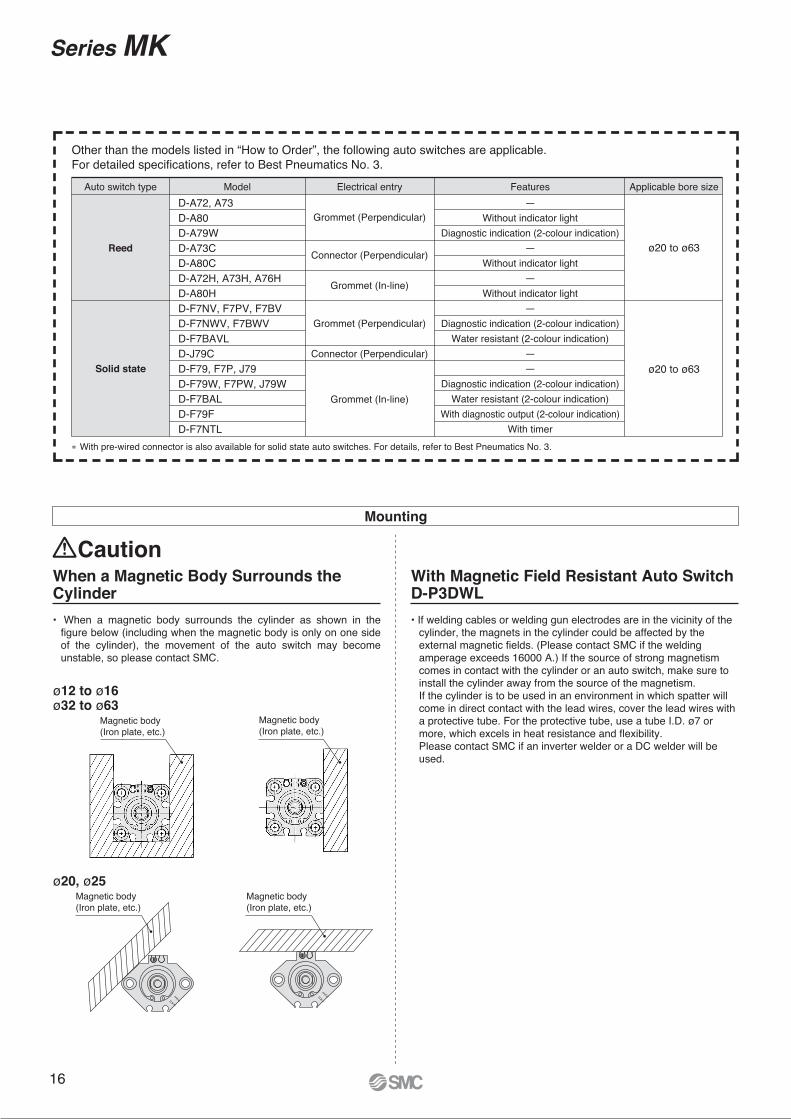
∗ With pre-wired connector is also available for solid state auto switches. For details, refer to Best Pneumatics No. 3.
Auto switch type Model FeaturesElectrical entryD-A72, A73D-A80D-A79WD-A73CD-A80CD-A72H, A73H, A76HD-A80HD-F7NV, F7PV, F7BVD-F7NWV, F7BWVD-F7BAVLD-J79CD-F79, F7P, J79D-F79W, F7PW, J79WD-F7BALD-F79FD-F7NTL
—Without indicator light
Diagnostic indication (2-colour indication)—
Without indicator light—
Without indicator light—
Diagnostic indication (2-colour indication)Water resistant (2-colour indication)
——
Diagnostic indication (2-colour indication)Water resistant (2-colour indication)
With diagnostic output (2-colour indication)With timer
Applicable bore size
ø20 to ø63
ø20 to ø63
Grommet (Perpendicular)
Connector (Perpendicular)
Grommet (In-line)
Grommet (Perpendicular)
Connector (Perpendicular)
Grommet (In-line)
Reed
Solid state
Other than the models listed in “How to Order”, the following auto switches are applicable.For detailed specifications, refer to Best Pneumatics No. 3.
With Magnetic Field Resistant Auto Switch D-P3DWL
When a Magnetic Body Surrounds the Cylinder
• When a magnetic body surrounds the cylinder as shown in the figure below (including when the magnetic body is only on one side of the cylinder), the movement of the auto switch may become unstable, so please contact SMC.
• If welding cables or welding gun electrodes are in the vicinity of the cylinder, the magnets in the cylinder could be affected by the external magnetic fields. (Please contact SMC if the welding amperage exceeds 16000 A.) If the source of strong magnetism comes in contact with the cylinder or an auto switch, make sure to install the cylinder away from the source of the magnetism.If the cylinder is to be used in an environment in which spatter will come in direct contact with the lead wires, cover the lead wires with a protective tube. For the protective tube, use a tube I.D. ø7 or more, which excels in heat resistance and flexibility.Please contact SMC if an inverter welder or a DC welder will be used.
Mounting
Magnetic body(Iron plate, etc.)
ø20, ø25
ø12 to ø16ø32 to ø63
Magnetic body(Iron plate, etc.)
Magnetic body(Iron plate, etc.)
Magnetic body(Iron plate, etc.)
Caution
Series MK
16

Auto SwitchConnections and Examples
Basic Wiring
Solid state 3-wire, NPN
• Sink input specification
3-wire, NPN
2-wire
• Source input specification
3-wire, PNP
2-wire 2-wire
Solid state 3-wire, PNP
Connect according to the PLC input specifications, since the connection method will differ depending on the PLC input specifications.
(Power supplies for switch and load are separate.)
Load
Example of AND (Serial) and OR (Parallel) Connection
Example of Connection to PLC (Programmable Logic Controller)
(Solid state)2-wire(Reed)
Switch main circuit
Brown
BlackLoad
Brown
Black
Blue
Load
Brown
Black
Blue
Load
Brown
Blue
Load
Brown
Blue
Indicator light, protectivecircuit,etc.
Brown
Blue
Load
Brown
BlueLoad
Switch main circuit
Switch main circuit
Switch main circuit
Switch main circuit
Indicator light, protectivecircuit,etc.
Blue
Switch
InputBlack
COM
Brown
Blue
Switch
Input
Blue COM
Brown
Switch
InputBlack
PLC internal circuitCOM
Brown
Blue
PLC internal circuit
PLC internal circuit
PLC internal circuit
Switch
InputBlue
COMBrown
• 3-wireOR connection for NPN output
2-switch OR connection
AND connection for NPN output
(using relays)
AND connection for NPN output
(performed with switches only)
The indicator lights will illuminate when both switches are turned ON.
Switch 1
Switch 2
Load
BrownBlackBlue
BrownBlackBlue
Switch 1
Brown
Switch 2
BlackBlue
Relay
Relay
BrownBlackBlue
Load
Relay contact
Switch 1
Brown
Switch 2
BlackBlue Load
BrownBlackBlue
Switch 1
Switch 2
Brown
Blue
Brown
Blue
LoadSwitch 1
Switch 2
Brown
Blue
Brown
Blue
Load
(Solid state) (Reed)When two switches are connected in series, a load may malfunction because the load voltage will decrease in the ON state.The indicator lights will illuminate if both switches are turned ON.
When two switches are connected in parallel, malfunction may occur because the load voltage will increase in the OFF state.
Because there is no leakage current, the load voltage will not increase in the OFF state. However, depending on the number of switches in the ON state, the indicator lights may sometimes dim or not light because of the dispersion and reduction of the current flowing to the switches.
Power supply ResidualLoad voltage at ON = voltage – voltage x 2 pcs. = 24 V – 4 V x 2 pcs. = 16 VExample) Power supply voltage: 24 VDC
Auto switch internal voltage drop: 4 V
Load voltage at OFF = Leakage current x 2 pcs. x Load impedance = 1 mA x 2 pcs. x 3 k = 6 VExample) Load impedance: 3 k
Auto switch leakage current: 1 mA
• 2-wire2-switch AND connection
17

RM∗
Q∗
ø20
8∗19∗
Q∗ �17–0.1–0.2
M10 x 1.525∗30 to 40
65
10
90
2215∗
ø20H
7
(Arm
sid
e I.D
.)
+0
.02
1
0
16∗
M∗
∗
Please contact SMC for detailed dimensions,specifications, and lead times.
Rotary Clamp Cylinder
Series MKMade to Order Individual Specifications
Max. Operating Pressure 1.0 MPa
Symbol
-X2071
63 N Z X2071MK Mounting Stroke Rotary direction
Nil
N
Without arm
With arm
Max. operating pressure
1.0 MPa
• Use this specification if the
pressure is between 0.61 and 1.0
MPa when using MK�63-��Z.
• The rod end and arm dimensions
are different from the standard.
• When an arm assembly is
ordered for this specification,
order it with the part number
[MK-A063-X2071]. (See below.)
Specifications
Body option
Arm Assembly Component Parts
Bore size (mm)
Operating pressure range
63
0.1 to 1.0 MPa
Overall Length Is the Same as the MK2 Series
Symbol
-X2094
Z X2094MK MountingBoresize Stroke
Rotarydirection Body option
Overall length is the same as the MK2 series
• The overall length Q (from the end on
the head side to the rod end) is the
same as the MK2 series.
Applicable bore size/StrokeBore size
ø20
ø25
ø32
ø40
ø50
ø63
Stroke
10, 20
20, 50
Construction/Dimensions Dimensions
With arm
Arm assembly
Rod
state
Retracted
Extended
Clamp stroke
10 mm
Q
146.5
175.5
166.5
205.5
186.5
235.5
20 mm 30 mm
226.5
295.5
50 mm
MK�63-�Z-X2071
Model
Retracted
Extended
Clamp stroke
10 mm
M
77.5
106.5
87.5
126.5
97.5
146.5
20 mm 30 mm
117.5
186.5
50 mm
MK�63-�Z-X2071
ModelRod
state
No. Description Material Note
1
2
3
4
5
6
Arm
Clamp bolt
Hexagon nut
Hexagon socket head cap screw
Spring washer
Hexagon socket head set screw
Rolled steel
Chromium molybdenum steel
Rolled steel
Chromium molybdenum steel
Hard steel
Chromium molybdenum steel
M12 x 25L
Flat point M8 x 8L
Rod
state
Bore
size
Retracted
Extended
Retracted
Extended
Retracted
Extended
Retracted
Extended
Retracted
Extended
Retracted
Extended
Q
10 mm 20 mm
Clamp stroke
95.5
115
98.5
118
121.5
146.5
122.5
147.5
—
—
—
—
72
72
73
73
81.5
81.5
75
75
—
—
—
—
23.5
43
25.5
45
40
65
47.5
72.5
—
—
—
—
R M
115.5
145
118.5
148
141.5
176.5
142.5
177.5
162
201
165
204
Q
82
82
83
83
91.5
91.5
85
85
96.5
96.5
100
100
R
33.5
63
35.5
65
50
85
57.5
92.5
65.5
104.5
65
104
M
ø20
ø25
ø32
ø40
ø50
ø63
(mm)
50 mm
—
—
—
—
—
—
—
—
222
291
225
294
Q
—
—
—
—
—
—
—
—
126.5
126.5
130
130
R
—
—
—
—
—
—
—
—
95.5
164.5
95
164
M
(The outline dimensions shown are when the rod is retracted.)Dimensions other than those marked with “∗” are the same as the standard.
(The outline dimensions shown are when the rod is retracted.)Dimensions other than those marked with “∗” are the same as the standard.
(mm)
(mm)
∗ Specifications other than the above are the same as the standard.
Without arm
MK-A063-X2071
Max. operating pressure 1.0 MPa
∗ The arm assembly consists of the parts No.1 to 6.
18

Symbol
-X2172With Boss in Head End3
Bore size
ø20
ø25
ø32
ø40
ø50
ø63
13
15
21
28
35
35
øAh9
Z X2172MKB Bore size Stroke Rotary direction Body option
Symbol
-X2177The Dimension of Head End Flange is the Same as the Existing Series MK and MK24
With boss in head end
Z X2177MKG Bore size Stroke Rotary direction Body option
The dimension of head end flange is the
same as the existing series MK and MK2
2
øA
h9
0−0.043
0−0.043
0−0.062
0−0.062
0−0.052
0−0.052
Bore size
ø20
ø25
ø32
ø40
ø50
ø63
48
52
56
62
76
92
25.5
28
—
—
—
—
¡The mounting dimension of head end flange and pin hole size are the same as the existing series MK and MK2.
Note) A centering location ring is used for the connection part between the cylinder and head end flange.
FY
FX
FX
ø32 to ø63
ø20, ø25
ø6.3+0.15+0.05 (two places)
ø6.3+0.15+0.05 (two places)
FX FY
Series MKMade to Order: Individual Specifications 2Please contact SMC for detailed dimensions, specifications, and lead times.
19

60° ±10° 60° ±10°
Clamp part
During clamping
(Retraction end)
Non-rotating accuracy
±0.7° to 1.4°Dimensions: Same as standard product
Symbol
-X2997Rotary Angle 60° Specifications5
MK Mounting Bore size Stroke Auto switchRotary direction Body option Z X2997
Rotary angle 60° specifications
∗ Specifications other than the above are the same as the standard.
Bore size (mm)
Rotary angle (°)Rotary stroke (mm)
12
5
16
5
20
6.3
25
6.3
32
10
40
10
50
12.7
63
12.7
60 ±10 During unclamping
(Extension end)
50° to 70°(60° ±10°)L type
(Counterclockwise)
During unclamping
(Extension end)
50° to 70°(60° ±10°)
R type
(Clockwise)
Port side
Rotary AngleSpecifications
MK Series
20

21
Safety Instructions Be sure to read “Handling Precautions for SMC Products” (M-E03-3) before using.
Lithuania +370 5 2308118 www.smclt.lt [email protected] +31 (0)205318888 www.smcpneumatics.nl [email protected] +47 67129020 www.smc-norge.no [email protected] +48 222119600 www.smc.pl [email protected] +351 226166570 www.smc.eu [email protected] +40 213205111 www.smcromania.ro [email protected] +7 8127185445 www.smc-pneumatik.ru [email protected] +421 413213212 www.smc.sk [email protected] +386 73885412 www.smc.si [email protected] +34 945184100 www.smc.eu [email protected] +46 (0)86031200 www.smc.nu [email protected] +41 (0)523963131 www.smc.ch [email protected] +90 (0)2124440762 www.entek.com.tr [email protected] UK +44 (0)845 121 5122 www.smcpneumatics.co.uk [email protected]
Specifications are subject to change without prior notice and any obligation on the part of the manufacturer.
SMC CORPORATION Akihabara UDX 15F, 4-14-1, Sotokanda, Chiyoda-ku, Tokyo 101-0021, JAPAN Phone: 03-5207-8249 FAX: 03-5298-53621st printing OU printing OU 00 Printed in Spain
Austria +43 2262622800 www.smc.at [email protected] +32 (0)33551464 www.smcpneumatics.be [email protected] +359 29744492 www.smc.bg [email protected] +385 13776674 www.smc.hr [email protected] Republic +420 541424611 www.smc.cz [email protected] +45 70252900 www.smcdk.com [email protected] Estonia +372 6510370 www.smcpneumatics.ee [email protected] +358 207513513 www.smc.fi [email protected] +33 (0)164761000 www.smc-france.fr [email protected] +49 (0)61034020 www.smc-pneumatik.de [email protected] +30 210 2717265 www.smchellas.gr [email protected] +36 23511390 www.smc.hu [email protected] +353 (0)14039000 www.smcpneumatics.ie [email protected] +39 (0)292711 www.smcitalia.it [email protected] +371 67817700 www.smclv.lv [email protected]
SMC Corporation (Europe)
1. The compatibility of the product is the responsibility of the
person who designs the equipment or decides its specifications.Since the product specified here is used under various operating conditions, its
compatibility with specific equipment must be decided by the person who designs
the equipment or decides its specifications based on necessary analysis and test
results. The expected performance and safety assurance of the equipment will be
the responsibility of the person who has determined its compatibility with the
product. This person should also continuously review all specifications of the
product referring to its latest catalogue information, with a view to giving due
consideration to any possibility of equipment failure when configuring the
equipment.
2. Only personnel with appropriate training should operate
machinery and equipment.The product specified here may become unsafe if handled incorrectly. The
assembly, operation and maintenance of machines or equipment including our
products must be performed by an operator who is appropriately trained and
experienced.
3. Do not service or attempt to remove product and
machinery/equipment until safety is confirmed.
1. The inspection and maintenance of machinery/equipment should only be
performed after measures to prevent falling or runaway of the driven objects
have been confirmed.
2. When the product is to be removed, confirm that the safety measures as
mentioned above are implemented and the power from any appropriate source
is cut, and read and understand the specific product precautions of all relevant
products carefully.
3. Before machinery/equipment is restarted, take measures to prevent
unexpected operation and malfunction.
4. Contact SMC beforehand and take special consideration of safety
measures if the product is to be used in any of the following
conditions.
1. Conditions and environments outside of the given specifications, or use
outdoors or in a place exposed to direct sunlight.
2. Installation on equipment in conjunction with atomic energy, railways, air
navigation, space, shipping, vehicles, military, medical treatment, combustion
and recreation, or equipment in contact with food and beverages, emergency
stop circuits, clutch and brake circuits in press applications, safety equipment
or other applications unsuitable for the standard specifications described in the
product catalogue.
3. An application which could have negative effects on people, property, or
animals requiring special safety analysis.
4. Use in an interlock circuit, which requires the provision of double interlock for
possible failure by using a mechanical protective function, and periodical
checks to confirm proper operation.
Warning
Limited warranty and Disclaimer/Compliance Requirements The product used is subject to the following “Limited warranty and Disclaimer”
and “Compliance Requirements”.
Read and accept them before using the product.
1. The product is provided for use in manufacturing industries.
The product herein described is basically provided for peaceful use in
manufacturing industries.
If considering using the product in other industries, consult SMC beforehand and
exchange specifications or a contract if necessary.
If anything is unclear, contact your nearest sales branch.
Caution
Limited warranty and Disclaimer
1. The warranty period of the product is 1 year in service or 1.5 years after
the product is delivered.∗2)
Also, the product may have specified durability, running distance or
replacement parts. Please consult your nearest sales branch.
2. For any failure or damage reported within the warranty period which is clearly our
responsibility, a replacement product or necessary parts will be provided.
This limited warranty applies only to our product independently, and not to any ot-
her damage incurred due to the failure of the product.
3. Prior to using SMC products, please read and understand the warranty terms
and disclaimers noted in the specified catalogue for the particular products.
∗2) Vacuum pads are excluded from this 1 year warranty.
A vacuum pad is a consumable part, so it is warranted for a year after it is delivered.
Also, even within the warranty period, the wear of a product due to the use of the vacuum pad
or failure due to the deterioration of rubber material are not covered by the limited warranty.
Compliance Requirements
1. The use of SMC products with production equipment for the manufacture of
weapons of mass destruction (WMD) or any other weapon is strictly prohibited.
2. The exports of SMC products or technology from one country to another are
governed by the relevant security laws and regulations of the countries involved
in the transaction. Prior to the shipment of a SMC product to another country,
assure that all local rules governing that export are known and followed.
These safety instructions are intended to prevent hazardous situations and/or equipment damage. These instructions indicate the level of potential hazard with the labels of “Caution,” “Warning” or “Danger.” They are all important notes for safety and must be followed in addition to International Standards (ISO/IEC)∗1), and other safety regulations.
∗1) ISO 4414: Pneumatic fluid power – General rules relating to systems.
ISO 4413: Hydraulic fluid power – General rules relating to systems.
IEC 60204-1: Safety of machinery – Electrical equipment of machines.
(Part 1: General requirements)
ISO 10218-1: Manipulating industrial robots - Safety.
etc.
Caution indicates a hazard with a low level of risk which, if not avoided, could result in minor or moderate injury.
Warning indicates a hazard with a medium level of risk which, if not avoided, could result in death or serious injury.
Caution:
Warning:
Danger :Danger indicates a hazard with a high level of risk which, if not avoided, will result in death or serious injury.
Safety Instructions