rotary drive products
TRANSCRIPT

BOSTON GEAR Gears, Bearings, Couplings and Shaft Accessories
A L T R A I N D U S T R I A L M O T I O N
Rotary Drive ProductsGears, Bearings, Couplings and Shaft Accessories
www.bostongear.com
701 Carrier DriveCharlotte, NC 28216 - USA704-588-5610Fax: 704-588-7181 P-1930-BG 3/14 Printed in USA
Altra Industrial Motion
All Customer Service phone numbers shown in bold
Electromagnetic Clutches and Brakes
Warner ElectricElectromagnetic Clutches and Brakes
New Hartford, CT - USA 1-800-825-6544For application assistance: 1-800-825-9050
St Barthelemy d’Anjou, France +33 (0) 2 41 21 24 24
Precision Electric Coils and Electromagnetic Clutches and Brakes
Columbia City, IN - USA 1-260-244-6183
Matrix InternationalElectromagnetic Clutches and Brakes, Pressure Operated Clutches and Brakes
Brechin, Scotland +44 (0) 1356 602000New Hartford, CT - USA 1-800-825-6544
Inertia DynamicsSpring Set Brakes; Power On and Wrap Spring Clutch/Brakes
New Hartford, CT - USA 1-800-800-6445
Linear Products
Warner LinearLinear Actuators Belvidere, IL - USA 1-800-825-6544For application assistance: 1-800-825-9050
St Barthelemy d’Anjou, France +33 (0) 2 41 21 24 24
Couplings
Ameridrives Couplings Mill Spindles, Ameriflex, Ameridisc
Erie, PA - USA 1-814-480-5000
Gear Couplings
San Marcos, TX - USA 1-800-458-0887
Bibby TurboflexDisc, Gear, Grid Couplings, Overload Clutches
Dewsbury, England +44 (0) 1924 460801Boksburg, South Africa +27 11 918 4270
TB Wood’sElastomeric Couplings
Chambersburg, PA - USA 1-888-829-6637– Press #5
For application assistance: 1-888-829-6637 – Press #7
General Purpose Disc Couplings
San Marcos, TX - USA 1-888-449-9439
Ameridrives Power TransmissionUniversal Joints, Drive Shafts, Mill Gear Couplings
Green Bay, WI - USA 1-920-593-2444
Huco DynatorkPrecision Couplings and Air Motors
Hertford, England +44 (0) 1992 501900Chambersburg, PA - USA 1-800-829-6637
Lamiflex CouplingsFlexible Couplings, Bearing Isolators, and Coupling Guards
São Paulo, SP - Brasil (11) 5679-6533
Heavy Duty Clutches and Brakes
Wichita ClutchPneumatic Clutches and Brakes
Wichita Falls, TX - USA 1-800-964-3262Bedford, England +44 (0) 1234 350311
Twiflex LimitedCaliper Brakes and Thrusters
Twickenham, England +44 (0) 20 8894 1161
Industrial ClutchPneumatic and Oil Immersed Clutches and Brakes
Waukesha, WI - USA 1-262-547-3357
Gearing
Boston GearEnclosed and Open Gearing, Electrical and Mechanical P.T. Components
Charlotte, NC - USA 1-800-825-6544For application assistance: 1-800-816-5608
Bauer Gear MotorGeared Motors
Esslingen, Germany +49 (711) 3518 0Somerset, NJ - USA 1-732-469-8770
Nuttall Gear and Delroyd Worm GearWorm Gear and Helical Speed Reducers
Niagara Falls, NY - USA 1-716-298-4100
Overrunning Clutches
Formsprag Clutch Overrunning Clutches and Holdbacks
Warren, MI - USA 1-800-348-0881– Press #1
For application assistance: 1-800-348-0881 – Press #2
Marland ClutchRoller Ramp and Sprag Type Overrunning Clutches and Backstops
South Beloit, IL - USA 1-800-216-3515
Stieber Clutch Overrunning Clutches and Holdbacks
Heidelberg, Germany +49 (0) 6221 30 47 0
Belted Drives and Sheaves
TB Wood’sBelted Drives
Chambersburg, PA - USA 1-888-829-6637 – Press #5
For application assistance: 1-888-829-6637 – Press #7
EngineeredBearing Assemblies
Kilian ManufacturingEngineered Bearing Assemblies
Syracuse, NY - USA 1-315-432-0700
For information concerning our sales offices in Asia Pacific check our website www.altramotion.com.cn

Boston Gear
Altra Industrial Motion
bostongear.com
Boston Gear is a global supplier of quality power transmission products to most major industrial markets. With unparalleled delivery programs and superior customer service, the power transmission consumer, distributor and OEMs who demand the best, count on Boston Gear.
Boston Gear provides an extensive off-the-shelf product offering of more than 20,000 products combined with the ability to custom engineer unique solutions when required. Products are designed to perform in an unlimited array of industrial applications from unit handling to food processing and everything in between including solutions for paper converting, corrugated, mixers, hoists, pumps and steel.
Altra is a leading multinational designer, producer and marketer of a wide range of mechanical power transmission products. We sell our products in over 70 countries throughout the world.
Our products are frequently used in critical applications, such as fail-safe brakes for elevators, wheelchairs and forklifts as well as in a wide range of high- volume manufacturing processes, where reliability and accuracy are important for both avoiding costly downtime and enhancing the overall efficiency of manufacturing operations.
Altra products are marketed under a variety of well recognized and established manufacturing brand names including Warner Electric, Boston Gear, TB Wood’s, and Formsprag Clutch.
Check out BostSpec2™, the online product configurator at bostongear.com. Just input your application’s requirements using the drop down menus to identify performance criteria. The right product will power its way up to the top.
• Download 2D and 3D CAD formats and dimensional line drawings.• Submit an online RFQ to the local distributor of your choice.
P-1930-BG 3/14 Boston Gear 800-825-6544 329
Boston GearBoston Gear is a leading global supplier of quality power transmission products to most major industrial markets including food processing, packaging machinery, material handling and many others. Along with unparalleled delivery programs and superior customer service, the power transmission consumer, distributor, and OEM who demand the best, count on Boston Gear.
Centric Products Mechanical & Pneumatic Overload ClutchesThe full family of Centric overload clutches includes Trig-O-Matic™, Trig-O-Matic Lite™, Model H units, pneumatic disconnect models, and VariTorque pneumatic models. Centric centrifugal clutches are also offered. Bore ranges from 1/2” to 4-11/16”. Torque ranges from 35 in.lb. to 88,500 in.lb.
See Catalog P-1500-BG
High Precision Planetary GearheadsThe Boston Gear line of servo gearheads has been designed for direct attachment to popular servomotors. In-line and right angle units are offered in a variety of single and double reduction ratios.
See Catalog P-1603-BG
Worm, Helical and Bevel Gear DrivesBoston Gear’s comprehensive line of enclosed gear drives includes worm, in-line and parallel-shaft heli-cal, miter, and spiral bevel. Flanged and non-flanged models, single and double reduction units, and right 90 drives are available. And with our Reducer Express™ service, we’ll ship any of our 15 million different speed reducer combinations, in stock or not, by air within 24 hours - or we’ll pay the freight.
See Catalog P-1485-BG

P-1930-BG 3/14 Boston Gear 800-825-6544 1
Stock Altered and Custom Worm and Worm Gears ...............................................................................................3-5 Selection and Reference Guide...............................................................................................................................6-12 Product Descriptions..............................................................................................................................................13-16
A SPUR GEARS Section Contents ................................................................................................................................................17 Pinions and Spur Gears ....................................................................................................................18-27, 37-46 Change Gears................................................................................................................................................28-32 Stem Pinions .......................................................................................................................................................33 Drawn Pinion Wire ..............................................................................................................................................34 Rack ...............................................................................................................................................................35, 47 Internal Gears................................................................................................................................................36, 48 Selection ........................................................................................................................................................49-62 Gear Gauge Sets.................................................................................................................................................62 B HELICAL GEARS
Section Contents ................................................................................................................................................63 Helical Gears..................................................................................................................................................64-65 Selection ........................................................................................................................................................66-68 Stock Altered and Custom Helical Gears .......................................................................................................3-5 C MITER AND BEVEL GEARS
Section Contents ................................................................................................................................................69 Miter Gears ....................................................................................................................................................70-73 Bevel Gears....................................................................................................................................................74-78 Selection ........................................................................................................................................................79-83 Stock Altered and Custom Miter & Bevel Gears............................................................................................3-5 D WORMS AND WORM GEARS
Section Contents ................................................................................................................................................85 Worms and Worm Gears ..............................................................................................................................86-95 Selection ........................................................................................................................................................96-98 E SHAFT ACCESSORIES
Selection Contents .............................................................................................................................................99 Shaft Couplings.........................................................................................................................................100-106 Universal Joints.........................................................................................................................................107-113 Shaft Collars, Set Screw and Clamping Collars ....................................................................................114-117 Washers and Bushings.............................................................................................................................118-119 Pulleys, Round Belt ..........................................................................................................................................120 Miniature Timing Belt & Pulley Selection................................................................................................121-134 F BEARINGS
Selection Contents ...........................................................................................................................................135 BOST-BRONZ (Oil-Impregnated Sintered Bronze) .............................................................................136-144 BEAR-N-BRONZ (660 Cast Bronze) .....................................................................................................145-153 Bronze Bearing Emergency Bank................................................................................................................154 BOStonE F-1 (Glass Filled Teflon) ........................................................................................................155-157 RULON® 641 Bearings ..........................................................................................................................158-159 BOStonE Molded Plastic .......................................................................................................................160-171 BOStonE Molded Nylon.........................................................................................................................172-173 Sleeve Bearing Engineering..................................................................................................................174-182 Anti-Friction (Ball Bearings) ..................................................................................................................183-197 Self-Aligning (Rod End & Spherical Bearings).....................................................................................198-206 Engineering.............................................................................................................................................207-211 Mounted Bearings..................................................................................................................................212-232 Rolling Element Bearing Engineering ..................................................................................................233-239G CHAINS
Section Contents...........................................................................................................................................241 Roller Chains .............................................................................................................................................242-252 Block Chains .....................................................................................................................................................253
Continued on next page
Table Of Contents

2 Boston Gear 800-825-6544 P-1930-BG 3/14
G CHAINS (continued) ...................................................................................................................................................... Leaf (Cable) Chains ..........................................................................................................................................253 Ladder Chains...................................................................................................................................................254 Miniature Roller Chains....................................................................................................................................255 Chain Pullers/Chain Breaking Tools...............................................................................................................256H SPROCKETS
Section Contents...........................................................................................................................................257 Roller Chain Drives ................................................................................................................................258-265 Miniature Chain Sprockets ...........................................................................................................................266 Roller Chain Sprockets..........................................................................................................................267-289 Block Chain Sprockets .................................................................................................................................290 Ladder Chain Sprockets........................................................................................................................291-292 Roller Chain Drive Tensioners ..............................................................................................................293-296 Idler Sprockets ..............................................................................................................................................293I ENGINEERING INFORMATION
SPUR GEARS Nomenclature.......................................................................................................................................298-299 Involute Form...............................................................................................................................................300 Diametral Pitch / Pressure Angle / Tooth Dimensions............................................................................301 Backlash / Undercut / Formulas................................................................................................................302 Lewis Formula .............................................................................................................................................303 HELICAL GEARS Nomenclature / Helix Angle .......................................................................................................................304 Formulas ......................................................................................................................................................305 Thrust Loads................................................................................................................................................306 MITER & BEVEL GEARS Nomenclature ..............................................................................................................................................307 Mounting Distance ......................................................................................................................................308 Tooth Strength / Thrust ..............................................................................................................................309 WORMS & WORM GEARS Hand / Efficiency / Thrust Loads ...............................................................................................................310 Formulas / Self-Locking .............................................................................................................................311 COUPLING / UNIVERSAL JOINTS ..................................................................................................................312 GENERAL INFORMATION How To Figure Horsepower & Torque ......................................................................................................313 Mountings / Alterations / Lubrication .......................................................................................................314 Materials / Styles / Keyways & Setscrews ...............................................................................................315 Sprockets, Sprocket Diameters .........................................................................................................316-318 Horsepower & Torque Capacity Of Shafting ............................................................................................319 Temperature Conversion Table .................................................................................................................320 Equivalent Table ..........................................................................................................................................321 Metric Conversion Chart ............................................................................................................................322 Application Classifications .................................................................................................................323-324 INDEX TO CATALOG NUMBERS.............................................................................................................325-328
Table Of Contents Continued

P-1930-BG 3/14 Boston Gear 800-825-6544 3
MODIFIED STOCK GEARING
24 HOURSHIPMENT
Modified Stock Gearing
Custom Gearing
To request a quote for a custom gear solution from Boston Gear, simply fill out the “Request For Quotation Form” on page 5, and
FAX to 800-387-0130. Or give us a call at 800-816-5608.
Not every job is alike and not every job requires the same solution.That’s why Boston Gear will configure a custom gear to suit you.Even though we have built our reputation on supplying a breadth ofstandard products for virtually any industry, we have forged a namefor ourselves as makers of quality custom gears. Custom doesn’thave to mean expensive and it doesn’t have to mean that it requireslong lead times.
Depending on the amount of tooling required and the complexity ofthe job, your custom gear solution can be delivered in days, notweeks. No matter how small or how large your job is, contact ourcustom engineering team for a customized quote.
Face Width Reduced
Keyway(s) Added
Tapped Holes Added (for set screws)
Hub Projection Reduced
Bore Enlarged
Hub Diameter Reduced
With thousands of stock gears available, chancesare we’ve got just what you’re looking for. If you find a stock gear that’s close to what you need, but not precisely right, that’s not a problem. We can modify most stock gears to meet your requirements and ship it within 24 hours. The full range of modifications we can provide are shown below.
With Boston Gear, stockgear modifications are quickand easy. Give us a call at
800-825-6544.
Keyways and boresavailable in commonmetric sizes.

Custom Gearing Capabilities
4 Boston Gear 800-825-6544 P-1930-BG 3/14
Gear Types
• Spur• Helical• Miter & Bevel• Worm & Worm Gear
AGMA Classes
AGMA 9 Non-Heat Treated, Spur & Helical Gears only
AGMA 8 Heat Treated & Non-Heat Treated, all other gears
Note: Worm & Worm Gears do not have AGMA Class listings, however Boston Gear manufacturing tolerances relate to AGMA 8.
Note: Circular Pitch (.0491”-1.0472”) or Module Pitch (.4mm-8mm) within the Diametral Pitch Limits are optional (refer to page 302).
Capacities
Tolerances
Geometric Dimensioning
Material
Backlash
Refer to Engineering Information found on pages 301and 309.Refer to engineering for backlash related to helical andworm gearing.
Lot Sizes25 pcs Minimum Quantity on 6" OD and less
Finishes63 RMS Minimum on gear teeth32 RMS Minimum on Bores, Shaved Gear Teeth, Ground
Worms, and Machined Surfaces
Gear Diametral Pitch Face Type Pitch Diameter Max.
Spur 64DP-3DP .250"-36.000" 5.000"
Helical 64DP-3DP .337"-24.000" 5.000"
Internal Spur 64DP-3DP 1.000"-24.000" 5.000"
Bevel & Miter 64DP-3DP .500"-24.000" 3.000"
Worm 48DP-3DP .333"-4.000" 12.000"
Worm Gear 48DP-3DP .420"-24.000" 5.000"
Shaved Gear 24DP-3DP 1.000"-24.000" 5.000"
Splines Consult Engineering
Diametral Circular Module Pitch Pitch (in.)
.4 63.500 .0495
.5 50.800 .0618
.6 42.333 .0742
.8 31.750 .0989
1 25.400 .1237
1.25 20.320 .1546
1.5 16.933 .1855
2 12.700 .2474
2.5 10.160 .3092
3 8.467 .3711
4 6.350 .4947
5 5.080 .6184
6 4.233 .7422
8 3.175 .9895
≤ 2" ≥ 2" Features Diameter Diameter
Bore Diameter .0005" .0010"
Ground O.D. .0005" .0010"
Turned O.D. .0020" .0020"
Bore Length .0020" .0020"
Keyway Width .0020" .0020"
Keyway Depth .0100" .0100"
Tapped Holes 2B Thread
≤ 2" ≥ 2" Features Diameter Diameter
Perpendicularity .0010" .0010"
Parallelism .0010" .0010"
Circular Runout .0010" .0010"
Flatness .0010" .0010"
Concentricity .0005" .0010"
Description Designation
Low Carbon Steels 11L17, 12L14, 12L15
Medium Carbon Steels 11L41, 1045
Low Carbon Alloy Steels 86(L)20* (*86L20 or 8620)
Medium Carbon Alloy Steels 41(L)30, 41(L)40, 41(L)50
Preheat Treated Steels 4140, 4150
Stainless Steels 17-4PH, 303, 304
Cast Iron Grade 25, Grade 30
Brass Free Cutting, Half Hard
Bronze
Non-Metallic Phenolic (NEMA“C”), Delron, Nylon

Custom Gearing “Request For Quotation” Form
P-1930-BG 3/14 Boston Gear 800-825-6544 5
Company Name Date
Address Ref.
City/State Zip Quantity Req.
Tel. No. Fax No. P.O. No.
Contact Name
FAX to 800-387-0130. Or give us a call at 800-816-5608.
Spur Helical Miter Bevel Worm Worm Gear
No. of Teeth
Pitch (DP, CP MOD)
Pressure Angle
Helix Angle
Hand (LH, RH)
Material
Face Width
Length Through Bore
Hub Diameter
Hub Projection
Bore Diameter
Keyway
Setscrew(s)
Teeth in Mating Gear
Center Distance
Mounting Distance
No. of Starts (Thread)
Outside Diameter
Heat Treat — Yes/No
Depth of Hardness
Special Information
Gear Type

Gear Selection
6 Boston Gear 800-825-6544 P-1930-BG 3/14
Stock Gears Pressure Description Application Angle (PA) Material
Pinions 14-1/2° Brass
and Parallel 20° Brass
Gears Shafts 14-1/2° Steel
20° Delrin
Pinions
and Parallel 14-1/2° Non-Metallic
Gears Shafts 14-1/2° Steel, Iron
20° Steel, Iron
Change Parallel 14-1/2°
Steel, IronGears Shafts
Stem Parallel 14-1/2°
SteelPinions Shafts
Drawn BrassPinion Parallel 14-1/2° SteelWire Shafts
14-1/2° NylonRack Use with 14-1/2° Steel Spur Gears 20° Steel
Internal Parallel 14-1/2° BrassGears Shafts 20° Brass
ParallelHelical and 90° SteelGears Non-Intersecting 14-1/2° Bronze Shafts
Straight 90° Nylon
Miter Intersecting 20° Brass
Gears Shafts Steel Iron
Spiral 90° Miter Intersecting 20° SteelGears Shafts
Straight 90° BrassBevel Intersecting 20° SteelGears Shafts Iron
Spiral 90° Bevel Intersecting 20° SteelGears Shafts
90° Worms/ Non-IntersectingWorm Gears
Shafts
90° Worms/ Non-Intersecting Worm Gears
Shafts
90° Worms/ Non-Intersecting Worm Gears Shafts
(PA)
14-1/2°
14-1/2°20°25°
14-1/2°20°25°
Thread
Single
SingleDoubleQuad
SingleDoubleQuad
Worm
AcetalNylon
Steel
Steel
Gear
AcetalMinlonBronze
Bronze
Iron
SpurGears
HelicalGears
MiterandBevelGears
WormsandWormGears

Reference Guide
P-1930-BG 3/14 Boston Gear 800-825-6544 7
Gear Catalog Reference Pages Horsepower Catalog Diametrical Pitch Selection and Torque Number Pitch Diameter Face Width Procedure Ratings Selection
48DP – 16DP .208" – 5.000" .062" – .313" 49 50 – 52 18 – 2164DP – 24DP .250" – 6.000" .125" – .250" 49 – 37 – 4232DP – 24DP .500" – 6.000" .187" – .250" 49 50 19 – 2048DP – 24DP .375" – 2.500" .125" – .250" 49 – 37 – 42
16DP – 8DP 1.000" – 3.500" .500" – 1.250" 49 52 – 55 22 – 2420DP – 3DP .750" – 36.000" .500" – 3.000" 49 51 – 57 20 – 2720DP – 5DP .600" – 36.000" .500" – 2.500" 49 58 – 62 42 – 46
20DP – 8DP 1.000" – 12.500" .375" – 1.250" 49 51 – 55 28 – 32
20DP – 6DP .287" – 1.750" 1.125" – 3.000" 49 51 – 56 33
48DP – 24DP .125" – .667" 48" Lengths 49 50 3448DP – 24DP .125" – .667" 48" Lengths 49 50 34
48DP – 24DP .104" – .208" .125" – .250" 49 50 3548DP – 3DP .104" – 1.167" .125" – 3.000" 49 50 – 57 3520DP – 4DP .450" – 1.750" .500" – 3.500" 49 58 – 62 47
48DP – 16DP 1.000" – 6.000" .125" – .312" 49 50 3664DP – 24DP 1.000" – 6.000" .125" – .250" 49 – 48
24TDP – 6TDP .333" – 6.000" .250" – 1.250" 66 67 – 68 64 – 65 8TDP – 6TDP 1.000" – 6.000" .750" – 1.250" 66 68 65
48DP – 16DP .312" – 2.000" .070" – .390" 79 80 70 – 7148DP – 24DP .312" – 1.500" .080" – .230" 79 80 7048DP – 4DP .375" – 7.000" .080" – 1.430" 79 80 – 81 70 – 728DP – 4DP 3.500" – 8.000" .750" – 1.333" 79 80 – 81 72
18DP – 5DP 1.000" – 5.000" .220" – 1.150" 79 83 73
48DP – 24DP .250" – 2.000" .090" – .260" 79 82 7420DP – 6DP .500" – 6.000" .180" – 1.070" 79 82 74 – 7716DP – 4DP 1.000" – 9.000" .420" – 1.400" 79 82 75 – 77
30DP – 8DP .430" – 4.250" .140" –.710" 79 83 78
48DP – 32DP24DP – 32DP 96 – 86 – 8848DP – 24DP
48DP – 4DP 96 97 – 98 86 – 94
16DP – 3DP 96 97 – 98 89 – 95
Worm
.333"to
1.500"
.333"to
3.000"
.625"to
4.000"
Gear
.417"to
4.167"
.417"to
6.000"
1.250"to
18.000"
Worm
.562"to
.812"
.562"to
5.250"
1.000"to
5.250"
Gear
.156"to
.219"
.156"to
1.500"
.312"to
2.000"
Tooth Gauge

Product Selection / Reference Guide
8 Boston Gear 800-825-6544 P-1930-BG 3/14
BOST-BRONZ®
OILIMPREGNATED
SINTEREDBRONZE
BEAR-N-BRONZ®
660 CASTBRONZE
BRONZEEMERGENCY
BEARING BANKS
BOStonE® F-1GLASS FILLED
TEFLON
Rulon®
BOStonE®
MOLDEDPLASTIC
PLAIN CYLINDRICAL FLANGED TYPE THRUST TYPE
Pages 138–140 Pages 141–142 Page 143
PLATE STOCK CORED BARS SOLID BARS
Page 143 Page 144 Page 144 PLAIN CYLINDRICAL CORED BARS SOLID BARS
Pages 146–150 Pages 151–153 Page 153
BOST-BRONZ & BEAR-N-BRONZ PLAIN CYLINDRICAL
Page 154 Page 156
FLANGED THRUST TYPE SOLID BARS (EXTRUDED)
Page 156 Page 157 Page 157
RULON® 641 BEARINGS PLAIN CYLINDRICAL FLANGED
Pages 158–159 Page 161 Page 161
ROLL END FOR TUBING EXTRA LENGTH BLIND ROLL END ADAPTER GUIDE ROLL & STANDARD PIPE BORE INSERTS FOR HEX SHAFT
Pages 162–168 Page 169 Page 169 Page 170 ROLLERS SHAFT CLIP STUB SHAFT FOR ROLLERS
Page 170 Page 171 Page 171
BOSTONE® F-1GLASS FILLED
TEFLON
BOSTONE®
MOLDED PLASTIC

Product Selection / Reference Guide
P-1930-BG 3/14 Boston Gear 800-825-6544 9
BALLBEARINGWHEELS
BOStonE®
MOLDEDNYLON
RADIALBALL
BEARINGS
THRUSTBALL
BEARINGS
BALLBEARINGSHEAVES
RODEND
BEARINGS
PLAIN CYLINDRICAL FLANGED THRUST TYPE CABLE PULLEYS
Page 172 Page 172 Page 173 Page 173
1600 SERIES 7500 SERIES 7600 SERIES 6900 SERIES
Pages 185–186 Page 187 Page 188 Page 189
3000 SERIES 400F SERIES FLANGED
Pages 190–191 Page 192
GROUND, UNBANDED 600 SERIES
Page 193 Page 194
2000 SERIES 2100 SERIES 2200 SERIES
Page 195 Page 196 Page 197
KF FEMALE SERIES HM-C SERIES CMHD MALE SERIES HM MALE SERIES HF-C FEMALE SERIES CFHD FEMALE SERIES HF FEMALE SERIES
Page 198 Page 199 Page 200 Page 201
HME MALE SERIES HMX MALE SERIES HFE FEMALE SERIES HFX FEMALE SERIES
Page 202 Page 203

Product Selection / Reference Guide
10 Boston Gear 800-825-6544 P-1930-BG 3/14
TAKE-UPFRAMES
SPHERICALBEARINGS
FLANGEDUNITS
SHAFTSUPPORTS
LHA-LHB-LHSS LHSSE-LHSSVV LS SERIES SERIES SERIES
Page 204 Page 205 Page 206
L, H, F, T, A PS/XL-S-MB SERIES SERIES
Page 213 Page 214
PPB SERIES PS SERIES XL SERIES L-SERIES H-SERIES
Page 215 Page 216 Page 217 Pages 218–219
SL/SH SERIES MB SERIES
Pages 220–221 Page 222
PS2/PS3 SERIES XL2/XL3 SERIES F SERIES SF/ST SERIES T-SERIES
Page 223 Page 224 Pages 225–226 Pages 227–228
MBF SERIES MBP SERIES
Page 229 Page 230
A SERIES TU SERIES
Page 231 Page 232
REPLACEMENTBEARINGS& LOCKING
COLLAR SERIES
PILLOWBLOCKS

Product Selection / Reference Guide
P-1930-BG 3/14 Boston Gear 800-825-6544 11
BUSHINGS
COUPLINGS
UNIVERSALJOINTS
WASHERS
PULLEYS
MINIATURETIMING BELTS& PULLEYS
INSERT (3 JAW) SPIDER RING SHEAR
FC Type – Pages 100-101 BF Type – Page 102 BG Type – Page 103
CLAMP MULTI-JAW RIGID SLEEVE
SCC Type – Page 104 FA Type – Page 105 CR Type – Page 105 FCP Type – Page 106
PIN & BLOCK FORGED MOLDED MOLDED WITH SLIDE EXTENSION
J Type – Pages 107–108 UJN Type – Pages 109–111 JP Type – Page 112 JPE Type – Page 113
SETSCREW CLAMPING–THREADED CLAMPING – 1 PIECE CLAMPING – 2 PIECE
SC Type – Page 114 CSC Type – Page 115 CS Type – Page 116 2CS Type – Page 117
HARDENED STEEL WASHERS SOFT STEEL BUSHINGS
Page 118 Page 119
GROOVED
Page 120 TIMING BELTS PULLEYS
Pages 121-124 & 130 Pages 125–129 & 131–134
COLLARS

Product Selection / Reference Guide
12 Boston Gear 800-825-6544 P-1930-BG 3/14
ROLLER,BLOCK &
LEAF CHAINS
SPROCKETS
DRIVETENSIONERS
MULTIPLE WIDTHS TRANSMISSION CONVEYOR SERIES HEAVY SERIES ANSI STANDARD SERIES
Page 243–244 Page 245 Page 245 Page 245
ATTACHMENTS HOLLOW PIN BLOCK LEAF (CABLE)
Page 251 Page 252 Page 253 Page 253 LADDER MINIATURE ROLLER CHAIN PULLERS & CHAIN CHAIN BREAKING TOOLS
Page 254 Page 255 Page 256
PLASTIC & STAINLESS ROLLER CHAIN BLOCK CHAIN LADDER CHAIN STEEL
Page 266 Pages 267–289 Page 290 Pages 291–292
TYPE LG TYPE BG TYPE HG &UG
Page 294 Pages 294-295 Page 296
SCREW/SPRING ADJUSTABLE SHAFT MOUNTED DRIVE TENSIONS

P-1930-BG 3/14 Boston Gear 800-825-6544 13
Boston Gear
n Parallel Shaft Applicationsn Reliability from Steel, Cast Iron and Brass
n More Cost Effective, Quieter Runningand Corrosion-Resistant Operationfrom Non-Metallic Options
n Higher Load Carrying Capacity with20° PA (Pressure Angle)
n Higher Contact Ratio for a Smoother, Quieter Operation with 14-1/2° PA
Boston spur gears are designed to transmit motion and power betweenparallel shafts. Configurations include spur, rack, pinion wire, stem pinions and internal gears; most with a selection of bores, keyways andset screws. Fine-pitch gears are available in plastic, brass, stainless steeland steel. Heavier pitch spurs are available in steel and cast iron. Stylesinclude plain, web, web with lightening holes or spoked. Change gearshave consecutive numbers of teeth for a variety of ratios.
Boston Gear manufactures both 14-1/2° and 20°PA, involute, full depthsystem gears. While 20°PA is generally recog nized as having higher loadcarrying capacity, 14-1/2°PA gears have extensive use. The lowerPressure Angle results in less change in backlash due to center distancevariation and concentricity errors. It also provides a higher contact ratioand is consequently a smoother, quieter operation provided that theundercut of the teeth is not present.
Selections From Stock• Pinions and Gears (Steel, Cast
Iron, Brass, Non-Metallic)• Change Gears (Steel or Cast
Iron)• Stem Pinions (Steel)• Drawn Pinion Wire (Brass,
Steel)• Rack (Steel, Nylon)• Internal (Brass)• Diametral Pitch 64 DP to 3 DP• Pitch Diameter .208" to
36.000"• Diametral Pitch System
Standardized on Stock Gears• 14-1/2° and 20° Pressure
Angles
Spur Gears
Boston Gear
14 Boston Gear 800-825-6544 P-1930-BG 3/14
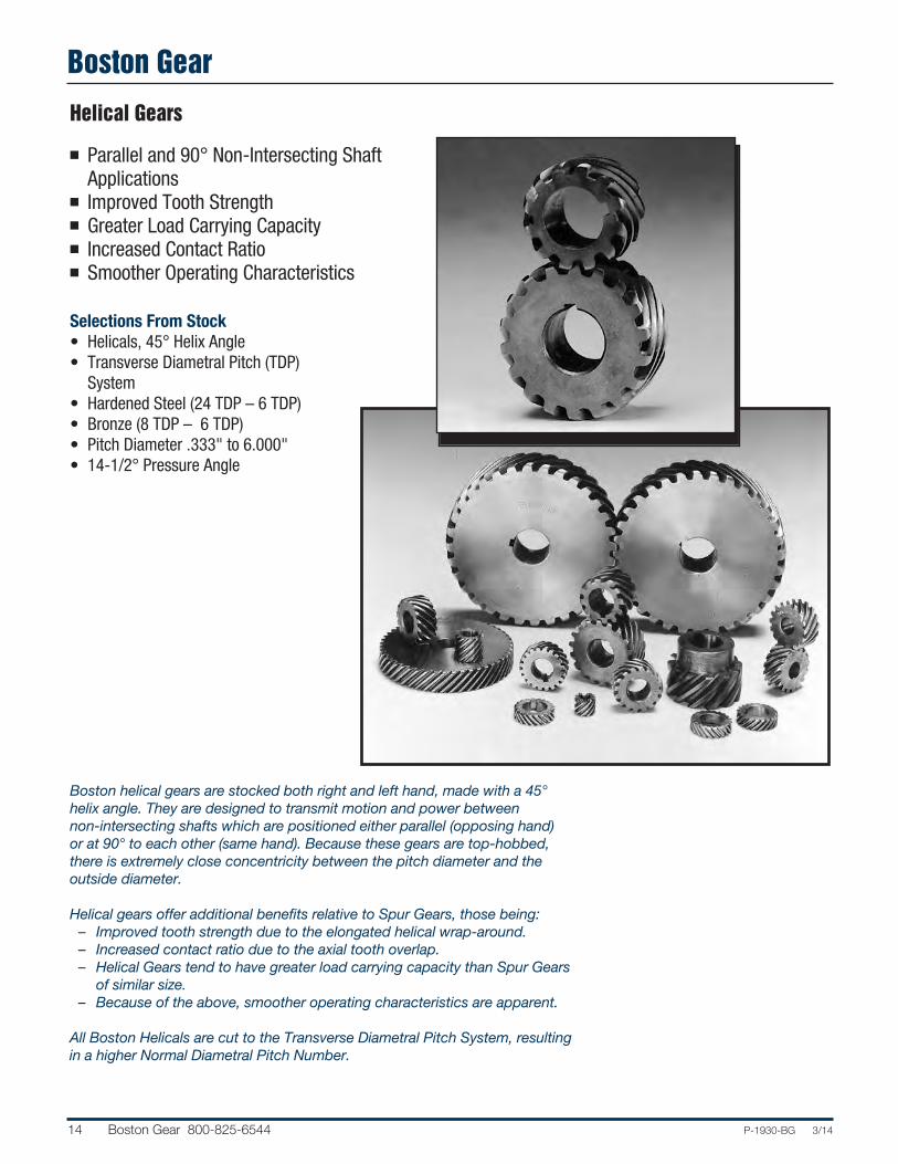
Helical Gears
n Parallel and 90° Non-Intersecting ShaftApplications
n Improved Tooth Strengthn Greater Load Carrying Capacityn Increased Contact Ration Smoother Operating Characteristics
Selections From Stock• Helicals, 45° Helix Angle• Transverse Diametral Pitch (TDP)
System• Hardened Steel (24 TDP – 6 TDP)• Bronze (8 TDP – 6 TDP)• Pitch Diameter .333" to 6.000"• 14-1/2° Pressure Angle
Boston helical gears are stocked both right and left hand, made with a 45°helix angle. They are designed to transmit motion and power between non-intersecting shafts which are positioned either parallel (opposing hand)or at 90° to each other (same hand). Because these gears are top-hobbed,there is extremely close concentricity between the pitch diameter and the outside diameter.
Helical gears offer additional benefits relative to Spur Gears, those being:– Improved tooth strength due to the elongated helical wrap-around.– Increased contact ratio due to the axial tooth overlap.– Helical Gears tend to have greater load carrying capacity than Spur Gearsof similar size.
– Because of the above, smoother operating characteristics are apparent.
All Boston Helicals are cut to the Transverse Diametral Pitch System, resultingin a higher Normal Diametral Pitch Number.

Boston Gear
P-1930-BG 3/14 Boston Gear 800-825-6544 15
n 90° Intersecting Shaft Applicationsn Coniflex® Tooth Form for Increased Life and Smoother, Quieter Operation
n Spiral Miter and Bevel for Higher Speed, Greater Torque Load, and Quieter Operating Applications
n Miter Gears for 1:1 Ratio Applicationsn Bevel Gears for 1.5:1 to 6:1 Ratio Applicationsn Soft Bores for Customized Alterations
Selections from Stock• Straight Miter Gears
– Nylon (48 DP – 16 DP)– Brass (48 DP – 24 DP)– Steel (48 DP – 4 DP)– Iron (8 DP – 4 DP)
• Spiral Miter Gears (35° Spiral Angle)– Steel (18 DP – 5 DP)
• Straight Bevel Gears– Brass (48 DP – 24 DP)– Steel (20 DP – 6 DP)– Iron (16 DP – 4 DP)
• Spiral Bevel Gears (35° Spiral Angle)– Steel (30 DP – 8 DP)
• Diametral Pitch – 48 DP to 4 DP• Pitch Diameter – 0.250" to 9.000"• 20° Pressure Angle• Hardened or Unhardened Teeth (Steel)• Made in Accordance with AGMA
Specifications for the Basic ToothForm
Boston miter and bevel gears are designed for transmission of motion andpower between intersecting shafts positioned at a right angle. Straight toothmiter and bevel gears are cut with a generated tooth form having a localizedlengthwise tooth bearings known as the “Coniflex”® tooth form. The superiorityof these gears over straight bevels with full length tooth bearing lies in the control of tooth contact. The localization of contact permits minor adjustmentof the gears in assembly and allows for some displacement due to deflectionunder operating loads, without concentration of the load on the end of thetooth. This results in increased life and quieter operation.
Spiral tooth form miter and bevel gears are suited for higher speed and largertorque applications.
®Registered trademark of The Gleason Works.
Miter and Bevel Gears

Boston Gear
16 Boston Gear 800-825-6544 P-1930-BG 3/14
Worms and Worm Gears
n 90° Non-Intersecting Shaft Applicationsn Smoothest, Quietest Form of Gearingn High Ratio Speed Reductionn Minimal Space Requirementsn Resistance to Back Driving with Some Ratios
n Increased Efficiency with Lower Ratios
Selections from Stock• Worms
– Acetal (48 DP – 24 DP)– Steel (48 DP – 3 DP)
• Worm Gears– Acetal (48 DP – 24 DP)– Bronze (48 DP – 4 DP)– Cast Iron (16 DP – 3 DP)
• Pressure Angle– 14-1/2°, 20°, 25°
• Thread– Single, Double, Quadruple
• Diametral Pitch – 48 DP to 3 DP• Center Distances – 0.375" to
11.000"
Boston Gear worms and worm gearsprovide an effective answer for suchpower transmission applications ashigh-ratio speed reduction, limitedspace, right-angle shafts and non-inter-secting shafts. When properly applied,they are the smoothest and quietest form of gearing. Steel worms and castiron or bronze worm gears having throated teeth are available in single ormultiple threads, 48 to 3 diametral pitch or up to 85" pitch diameter. Acetalworms and worm gears are available in 48, 32 and 24 diametral pitches.
The efficiency of a worm gear drive depends on the lead angle and number ofstarts on the worm. The angle generally decreases with increasing ratio andworm pitch diameter. For increased efficiency the ratio should be kept low.
P-1930-BG 3/14 Boston Gear 800-825-6544 17
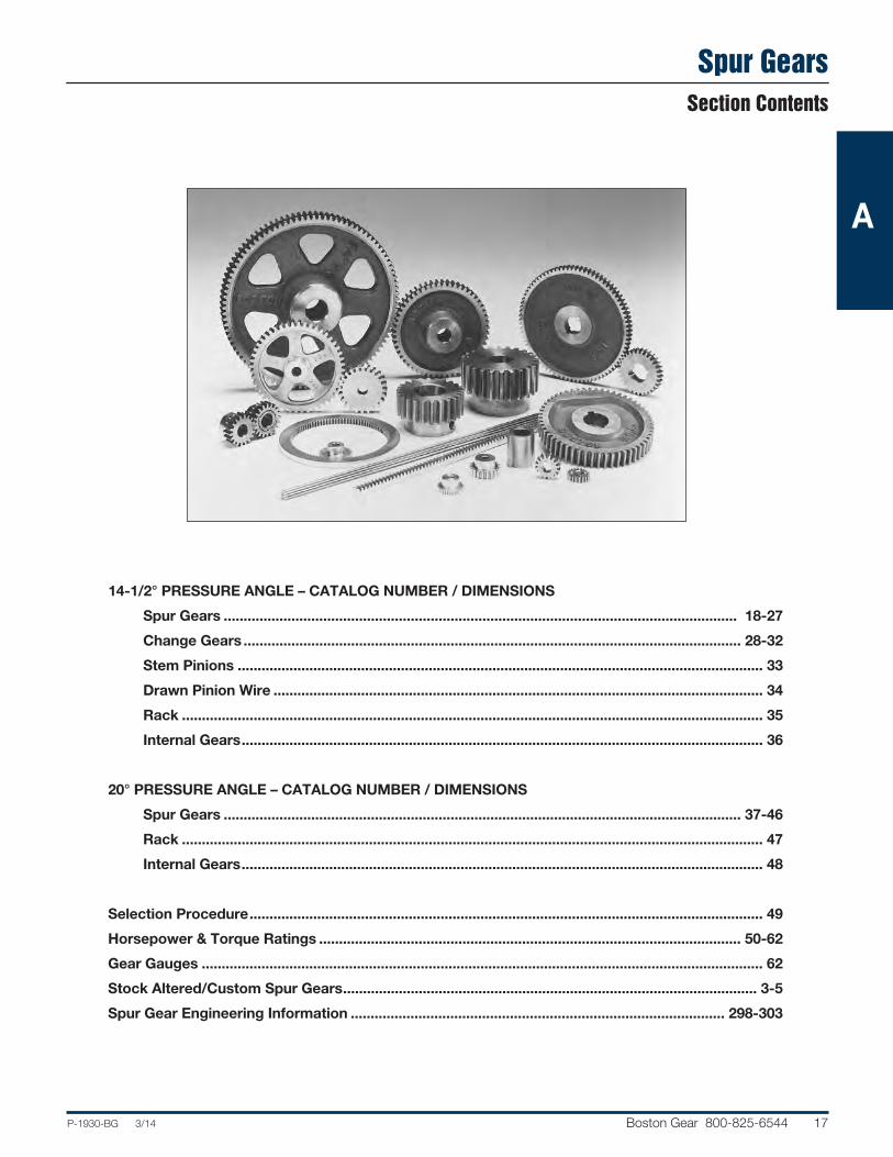
Spur Gears
14-1/2° PRESSURE ANGLE – CATALOG NUMBER / DIMENSIONS
Spur Gears ................................................................................................................................. 18-27
Change Gears ............................................................................................................................. 28-32
Stem Pinions .................................................................................................................................... 33
Drawn Pinion Wire ........................................................................................................................... 34
Rack .................................................................................................................................................. 35
Internal Gears................................................................................................................................... 36
20° PRESSURE ANGLE – CATALOG NUMBER / DIMENSIONS
Spur Gears .................................................................................................................................. 37-46
Rack .................................................................................................................................................. 47
Internal Gears................................................................................................................................... 48
Selection Procedure................................................................................................................................. 49
Horsepower & Torque Ratings .......................................................................................................... 50-62
Gear Gauges ............................................................................................................................................. 62
Stock Altered/Custom Spur Gears........................................................................................................ 3-5
Spur Gear Engineering Information .............................................................................................. 298-303
Section Contents
A

Spur Gears
18 Boston Gear 800-825-6544 P-1930-BG 3/14
STANDARD TOLERANCES
DIMENSION TOLERANCE
BORE All ±.0005
48 and 32 Diametral Pitch (Brass)14-1/2° Pressure Angle (will not operate with 20° spurs)
REFERENCE PAGES
Alterations — 314Lubrication — 314Materials — 315
48 D.P. 32 D.P.
BORE HUBDIA.
HUBPROJ.FACE
PITCHDIA.
OVERALLLENGTH
ALL DIMENSIONS IN INCHESORDER BY CATALOG NUMBER OR ITEM CODE
Style Without Keyway No. Hub See or Setscrew
of Pitch Page Catalog Item Teeth Dia. Bore Dia. Proj. 315 Number Code
Face = .125" 48 Outside Dia. = Pitch Dia. + .042" DIAMETRAL PITCH Overall Length = .125" + Hub Proj.
BRASS
10 .208 .0935 – – G127 09322 12 .250 G129 09324 14 .292 G130 09326 15 .312 .125 – – G131 09328 16 .333 G132 09330 18 .375 G133 09332 20 .417 G134 09334 22 .458 G135 09336 24 .500 G136 09338 26 .542 G137 09340 32 .667 .1875 – – A G138 09342 36 .750 G139 09344 40 .833 G140 09346 44 .917 G141 09348 48 1.000 G142 09350 54 1.125 G143 09352 60 1.250 G144 09354 66 1.375 .250 .50 .25 G145 09356 72 1.500 G146 09358 84 1.750 G147 09360 96 2.000 G148 09362 100 2.083 G154 09364 120 2.500 .3125 .62 .31 D G149 09366 144 3.000 G150 09368 192 4.000 G151 09370
32 Face = .062" DIAMETRAL PITCH Outside Dia. = Pitch Dia. + .062"
BRASS
10 .312 .125 – – G96 09234 14 .438 G98 09238 16 .500 G99 09240 20 .625 G101 09244 24 .750 .1875 – – G102 09246 28 .875 G103 09248 32 1.000 A G104 09250 40 1.250 .250 – – G105 09252 48 1.500 G106 09254 64 2.000 G110 09256 80 2.500 .3125 – – G111 09258 96 3.000 G112 09260 112 3.500 G113 09262 128 4.000 .375 – – G114 09264 Face = .188"
8 .250 G159 09266 10 .312 G161 09268 12 .375 .125 – – G163 09270 14 .438 G165 09272 15 .469 G166 09274 16 .500 G167 09276 18 .562 G168 09278 20 .625 G169 09280 22 .688 .1875 – – A G170 09282 24 .750 G171 09284 26 .812 G172 09286 28 .875 G173 09288 30 .938 G174 09290 32 1.000 G175 09292 36 1.125 G176 09294 40 1.250 .250 – – G177 09296 44 1.375 G178 09298 48 1.500 G179 09300 52 1.625 G180 09302 56 1.750 .3125 – – G181 09304
A

P-1930-BG 3/14 Boston Gear 800-825-6544 19
Spur Gears
32 and 24 Diametral Pitch (Brass & Steel)14-1/2° Pressure Angle (will not operate with 20° spurs)
STANDARD TOLERANCES
DIMENSION TOLERANCE
BORE All ±.0005
REFERENCE PAGES
Alterations — 314Horsepower Ratings — 50Lubrication — 314Materials — 315Selection Procedure — 49
32 D.P. 24 D.P.
BORE HUBDIA.
HUBPROJ.FACE
PITCHDIA.
OVERALLLENGTH
ALL DIMENSIONS IN INCHESORDER BY CATALOG NUMBER OR ITEM CODE
Style Without Keyway With No. Hub See or Setscrew Setscrew
of Pitch Page Catalog Item Catalog Item Teeth Dia. Bore Dia. Proj. 315 Number Code Number Code
Face = .188" 32 Outside Dia. = Pitch Dia. + .062" DIAMETRAL PITCH Overall Length = .187" + Hub Proj.
BRASS
64 2.000 .25 B G182 09306 – – 72 2.250 C G183 09308 – – 80 2.500 .3125 .62 G184 09310 – – 96 3.000 .31 D G185 09312 – – 112 3.500 G186 09314 – – 128 4.000 .75 G187 09316 – –
STEEL
16 .500 .1875 – – S3216 09572 – – 20 .625 S3220 09574 – – 22 .688 .250 – – S3222 09576 – – 24 .750 .3125 – – S3224 09578 – – 28 .875 .375 – – S3228 09580 – – 32 1.000 .3125 S3232 09582 – – 40 1.250 S3240 09584 – – 48 1.500 S3248 09586 – – 56 1.750 .375 – – S3256 09588 – – 64 2.000 S3264 09590 – – 80 2.500 S3280 09592 – – 96 3.000 S3296 09594 – – 16 .500 .39 – – H3216 09536 18 .562 .1875 .45 .31 – – H3218 09538 20 .625 .52 A – – H3220 09540 22 .688 .250 .58 .31 – – H3222 09542 24 .750 .64 – – H3224 09544 26 .812 .70 – – H3226 09546 28 .875 .3125 .75 .31 – – H3228 09548 30 .938 .75 – – H3230 09550 32 1.000 .75 .38 – – H3232 09552 40 1.250 – – H3240 09554 48 1.500 .88 .38 – – H3248 09556 56 1.750 – – H3256 09558 64 2.000 1.00 .38 – – H3264 09560 80 2.500 .375 1.12 .38 – – H3280 09562 96 3.000 1.25 .50 – – H3296 09564 128 4.000 1.88 .50 – – H32128 09566 160 5.000 2.12 .50 – – H32160 09568 192 6.000 2.12 .50 – – H32192 09570 Face = .250" 24 Outside Dia. = Pitch Dia. + .083" DIAMETRAL PITCH Overall Length = .250" + Hub Proj.
BRASS
12 .500 .38 G254 09202 – – 16 .667 .1875 .50 .25 G256 09204 – – 18 .750 .50 A G257 09206 – – 24 1.000 G258 09208 – – 30 1.250 .250 .62 .25 G259 09210 – – 36 1.500 G261 09212 – – 42 1.750 .62 .25 B G263 09214 – – 48 2.000 G264 09216 – – 54 2.250 .3125 .69 .31 C G265 09218 – – 60 2.500 G266 09220 – – 66 2.750 G267 09222 – – 72 3.000 .75 .31 G268 09224 – – 84 3.500 .75 .31 G269 09226 – – 96 4.000 .375 .75 .31 D G270 09228 – – 120 5.000 .88 .38 G272 09230 – – 144 6.000 .88 .38 G274 09232 – –
A

Spur Gears
20 Boston Gear 800-825-6544 P-1930-BG 3/14
ALL DIMENSIONS IN INCHESORDER BY CATALOG NUMBER OR ITEM CODE
Style Without Keyway With Keyway No. Hub See or Setscrew & Setscrew†
of Pitch Page Catalog Item Catalog Item Teeth Dia. Bore Dia. Proj. 315 Number Code Number Code
Face = .250" 24 Outside Dia. = Pitch Dia. + .083" DIAMETRAL PITCH Overall Length = .250" + Hub Proj.
STEEL
12 .500 .250 – – S2412 09630 – – 15 .625 – – S2415 09632 – – 16 .667 .3125 – – S2416 09634 – – 18 .750 – – S2418 09636 – – 21 .875 .375 – – S2421 09638 – – 24 1.000 S2424 09640 – – 30 1.250 S2430 09642 – – 36 1.500 S2436 09644 – – 42 1.750 .500 – – S2442 09646 – – 48 2.000 S2448 09648 – – 60 2.500 S2460 09650 – – 72 3.000 S2472 09652 – – 12 .500 .36 – – H2412† 09596 14 .583 .250 .46 .31 A – – H2414† 09598 15 .625 .50 – – H2415‡ 09600 16 .667 .54 – – H2416 09602 18 .750 .3125 .62 .31 – – H2418 09604 20 .833 .70 – – H2420 09606 21 .875 .74 .31 – – H2421 09608 24 1.000 .87 – – H2424 09610 30 1.250 1.00 – – H2430 09612 36 1.500 .375 1.12 .38 – – H2436 09614 42 1.750 1.12 – – H2442 09616 48 2.000 1.25 – – H2448 09618 60 2.500 1.25 – – H2460 09620 72 3.000 1.38 – – H2472 09622 96 4.000 .500 2.00 .50 – – H2496 09624 120 5.000 2.25 – – H24120 09626 144 6.000 2.25 – – H24144 09628 Face = .375" 20 Outside Dia. = Pitch Dia. + .100" DIAMETRAL PITCH Overall Length = .375" + Hub Proj.
STEEL
11 .600* .46 NA11B 09662 NA11B-5/16** 46000 12 .600 .3125 .46 .38 NA12B 09664 NA12B-5/16** 46001 13 .650 .50 NA13B 09666 NA13B-5/16** 46002 14 .700 .56 NA14B 09668 NA14B-5/16** 46003 15 .750 .60 NA15B 09670 NA15B-3/8†† 46004 16 .800 .375 .66 .38 NA16B 09672 NA16B-3/8†† 46005 18 .900 .74 NA18B 09674 NA18B-3/8†† 46006 20 1.000 .375 .84 .38 NA20B 09676 NA20B-3/8†† 46007 .500 – – NA20B-1/2†† 46008 22 1.100 .375 .82 .38 NA22B 09678 NA22B-3/8†† 46009 .500 – – NA22B-1/2†† 46010 24 1.200 .375 .92 .38 NA24 09680 NA24-3/8†† 46011 .500 – – NA24-1/2†† 46012 25 1.250 .375 .97 .38 NA25B 09682 NA25B-3/8†† 46013 .500 – – NA25B-1/2†† 46014 28 1.400 .375 1.12 .38 A NA28B 09684 NA28B-3/8†† 46015 .500 – – NA28B-1/2†† 46016 30 1.500 .375 1.22 .38 NA30B 09686 NA30B-3/8†† 46017 .500 – – NA30B-1/2†† 46018 32 1.600 .375 1.32 .50 NA32 09688 NA32-3/8†† 46019 .500 – – NA32-1/2†† 46020 35 1.750 .375 1.47 .50 NA35 09690 NA35-3/8†† 46021 .500 – – NA35-1/2†† 46022 36 1.800 .375 1.52 .50 NA36 09692 NA36-3/8†† 46023 .500 – – NA36-1/2†† 46024 .375 NA40 09694 NA40-3/8†† 46025 40 2.000 .500 1.72 .50 – – NA40-1/2†† 46026 .625 – – NA40-5/8 46027 .750 – – NA40-3/4 46028 48 2.400 1.33 NA48A 10208 – – 50 2.500 .375 1.42 .50 NA50A 10210 – – 60 3.000 1.92 NA60A 10212 – – 64 3.200 2.12 NA64A 10214 – –
24 and 20 Diametral Pitch (Steel)14-1/2° Pressure Angle (will not operate with 20° spurs)
STANDARD TOLERANCES
DIMENSION TOLERANCE
BORE All ±.0005
REFERENCE PAGES
Alterations — 314Horsepower Ratings — 50, 51Lubrication — 314Materials — 315Selection Procedure — 49
*Special Pitch Diameter, used for calculating CenterDistance only, not Ratio.
†H2412 & H2414 have #35 (.110) drilled hole throughone wall, no keyway.
‡H2415-H24144 has one setscrew, no keyway.
**NA11B-5/16"-NA14B-5/16 bore has #35 (.110) drilledhole through one wall, no keyway.
††3/8" & 1/2" bores have one setscrew, no keyway.
NA40-5/8" & NA40-3/4" bores have standard keywayat 90° to setscrew. See Page 315.
BORE HUBDIA.
HUBPROJ.FACE
PITCHDIA.
OVERALLLENGTH
KEYWAY
20 D.P. 24 D.P.
A

Spur Gears
P-1930-BG 3/14 Boston Gear 800-825-6544 21
ALL DIMENSIONS IN INCHESORDER BY CATALOG NUMBER OR ITEM CODE
Style Without Keyway With Keyway No. Hub See or Setscrew and Setscrew†
of Pitch Page Catalog Item Catalog Item Teeth Dia. Bore Dia. Proj. 315 Number Code Number Code
Face = .375” 20 Outside Dia. = Pitch Dia. + .100” DIAMETRAL PITCH Overall Length = .375” + Hub Proj.
CAST IRON
70 3.500 .375 1.25 .50 NA70 10216 – – 72 3.600 B NA72 10218 – – 80 4.000 NA80 10220 – – 84 4.200 NA84 10222 – – 90 4.500 .500 1.25 .50 C NA90 10224 – – 96 4.800 NA96 10226 – – 100 5.000 NA100 10228 – – 112 5.600 NA112 10230 – – 120 6.000 NA120 10232 – – 140 7.000 1.50 .50 D NA140 10234 – – 144 7.200 .500 NA144 10236 – – 160 8.000 NA160 10238 – – 180 9.000 .62 NA180 10240 – – 200 10.000 2.25 NA200B 10242 – – Face = .313" 16 Outside Dia. = Pitch Dia. + .125" DIAMETRAL PITCH Overall Length = Face + Hub Proj.
BRASS
8 .500 .1875 – – G226 09168 – – 9 .563 G227 09170 – – 10 .625 G228 09172 – – 12 .750 G229 09174 – – 14 .875 .250 – – A G230 09176 – – 16 1.000 G231 09178 – – 18 1.125 G232 09180 – – 20 1.250 G233 09182 – – 24 1.500 .3125 – – G235 09184 – – 28 1.750 – – G236 09186 – – 32 2.000
.3125 .75 .31 B G237 09188 – –
40 2.500 G238 09190 – – 48 3.000 G239 09192 – – 56 3.500 .88 D G240 09194 – – 64 4.000 .375 1.00 .38 G241 09196 – – 80 5.000 1.00 G242 09198 – – STEEL Face = .500"
11 .750* .56 NB11B 09704 NB11B-3/8† 46029 12 .750 .375 .56 .44 NB12B 09706 NB12B-3/8† 46030 13 .813 .63 NB13B 09708 NB13B-3/8† 46031 14 .875 .69 NB14B 09710 NB14B-3/8† 46032 15 .938 .75 NB15B 09712 NB15B-1/2† 46033 16 1.000 .500 .81 .44 NB16B 09714 NB16B-1/2† 46034 18 1.125 .94 NB18B 09716 NB18B-1/2† 46035 20 1.250 .500 .96 .44 NB20B 09718 NB20B-1/2† 46036 .625 – – NB20B-5/8 46037 22 1.375 .500 1.08 .44 NB22B 09720 NB22B-1/2† 46038 .625 – – NB22B-5/8 46039 .500 NB24B 09722 NB24B-1/2† 46040 24 1.500 .625 1.20 .44 A – – NB24B-5/8 46041 .750 – – NB24B-3/4 46042 .500 NB26B 09724 NB26B-1/2† 46043 26 1.625 .625 1.33 .44 – – NB26B-5/8 46044 .750 – – NB26B-3/4 40645 .500 NB28B 09726 NB28B-1/2† 46046 28 1.750 .625 1.45 .50 – – NB28B-5/8 46047 .750 – – NB28B-3/4 46048 .875 – – NB28B-7/8 46049 .500 NB30B 09728 NB30B-1/2† 46050 .625 – – NB30B-5/8 46051 30 1.875 .750 1.58 .50 – – NB30B-3/4 46052 .875 – – NB30B-7/8 46053 1.000 – – NB30B-1 46054
STANDARD TOLERANCES
DIMENSION TOLERANCE
BORE All ±.0005
20 D.P. 16 D.P.
BORE HUBDIA.
HUBPROJ.FACE
PITCHDIA.
OVERALLLENGTH
KEYWAY
20 and 16 Diametral Pitch (Cast Iron, Brass & Steel)14-1/2° Pressure Angle (will not operate with 20° spurs)
REFERENCE PAGES
Alterations — 314Horsepower Ratings — 51, 52Lubrication — 314Materials — 315Selection Procedure — 49
*Special Pitch Diameter, used for calculating CenterDistance only, not Ratio.
†3/8" and 1/2" bores have one setscrew, no keyway.
5/8" bore and larger have standard keyway at 90° tosetscrew. See Page 315.
A

Spur Gears
22 Boston Gear 800-825-6544 P-1930-BG 3/14
ALL DIMENSIONS IN INCHESORDER BY CATALOG NUMBER OR ITEM CODE
Style Without Keyway With Keyway No. Hub See or Setscrew and Setscrew†
of Pitch Page Catalog Item Catalog Item Teeth Dia. Bore Dia. Proj. 315 Number Code Number Code
Face = .500" 16 Outside Dia. = Pitch Dia. + .125" DIAMETRAL PITCH Overall Length = .500" + Hub Proj.
STEEL
.500 NB32 09730 NB32-1/2 46055 .625 – – NB32-5/8 46056 32 2.000 .750 1.70 .50 – – NB32-3/4 46057 .875 A – – NB32-7/8 46058 1.000 – – NB32-1 46059 36 2.250 1.95 NB36 09732 – – 40 2.500 .500 1.69 .50 NB40A 10244 – – 48 3.000 2.19 NB48A 10246 – –
NON-METALLIC
16 1.000 .375 .81 .50 QBH16 09014 – – 20 1.250 1.06 QBH20 09018 – – 24 1.500 1.31 .50 QBH24 09022 – – 32 2.000 1.81 .50 A QBH32 09024 – – 40 2.500 .500 – – QB40 09000 – – 48 3.000 – – QB48 09002 – – 64 4.000 – – QB64 09006 – –
CAST IRON
54 3.375 1.25 .50 NB54 10248 – – 56 3.500 .500 1.25 .50 B NB56 10250 – – 60 3.750 1.38 .62 NB60 10252 – – 64 4.000 1.38 NB64 10254 – – 72 4.500 1.38 C NB72 10256 – – 80 5.000 1.50 NB80 10258 – – 84 5.250 .625 1.50 .62 NB84 10260 – – 96 6.000 1.50 NB96 10262 – – 112 7.000 1.50 NB112 10264 – – 120 7.500 1.50 NB120 10266 – – 128 8.000 1.50 D NB128 10268 – – 144 9.000 1.75 NB144 10270 – – 160 10.000 .625 1.75 .75 NB160B 10272 – – 192 12.000 2.00 NB192B 10274 – – Face = .750" 12 Outside Dia. = Pitch Dia. + .167" DIAMETRAL PITCH Overall Length = .750" + Hub Proj.
STEEL
11 1.000* .75 ND11B 09744 ND11B-1/2† 46060 12 1.000 .500 .75 .50 ND12B 09746 ND12B-1/2† 46061 13 1.083 .83 ND13B 09748 ND13B-1/2† 46062 14 1.167 .92 ND14B 09750 ND14B-1/2† 46063 15 1.250 1.00 ND15B 09752 ND15B-5/8 46064 16 1.333 .625 .99 .50 ND16B 09754 ND16B-5/8 46065 18 1.500 1.15 ND18B 09756 ND18B-5/8 46066 20 1.667 .625 1.32 .50 ND20B 09758 ND20B-5/8 46067 .750 – – ND20B-3/4 46068 .625 ND21B 09760 ND21B-5/8 46069 21 1.750 .750 1.40 .50 – – ND21B-3/4 46070 .875 A – – ND21B-7/8 46071 .625 ND22B 09762 ND22B-5/8 46072 22 1.833 .750 1.49 .50 – – ND22B-3/4 46073 .875 – – ND22B-7/8 46074 1.000 – – ND22B-1 46075 .625 ND24B 09764 ND24B-5/8 46076 24 2.000 .750 1.65 .50 – – ND24B-3/4 46077 .875 – – ND24B-7/8 46078 1.000 – – ND24B-1 46079 30 2.500 2.15 ND30 09766 – – 32 2.667 1.92 ND32A 10276 – – 36 3.000 .625 2.25 .62 ND36A 10278 – – 40 3.333 2.34 ND40A 10280 – – 42 3.500 2.50 ND42A 10282 – –
16 and 12 Diametral Pitch (Steel, Non-Metallic & Cast Iron)14-1/2° Pressure Angle (will not operate with 20° spurs)
STANDARD TOLERANCES
DIMENSION TOLERANCE
BORE All ±.0005
REFERENCE PAGES
Alterations — 314Horsepower Ratings — 52, 53Lubrication — 314Materials — 315Selection Procedure — 49
*Special Pitch Diameter, used for calculating CenterDistance only, not Ratio.
†1/2" bore has one setscrew, no keyway.
5/8" bore and larger have standard keyway at 90° tosetscrew. See Page 315.
16 D.P. 12 D.P.
BORE HUBDIA.
HUBPROJ.FACE
PITCHDIA.
OVERALLLENGTH
KEYWAY
A

Spur Gears
P-1930-BG 3/14 Boston Gear 800-825-6544 23
ALL DIMENSIONS IN INCHESORDER BY CATALOG NUMBER OR ITEM CODE
Style Without Keyway With Keyway No. Hub See or Setscrew and Setscrew†
of Pitch Page Catalog Item Catalog Item Teeth Dia. Bore Dia. Proj. 315 Number Code Number Code
Face = .750" 12 Outside Dia. = Pitch Dia. + .167" DIAMETRAL PITCH Overall Length = .750" + Hub Proj.
NON-METALLIC
15 1.250 1.00 QDH15 09038 – – 18 1.500 .500 1.25 .50 QDH18 09042 – – 21 1.750 1.50 QDH21 09046 – – 24 2.000 1.75 A QDH24 09050 – – 30 2.500 .625 2.25 .50 QDH30 09052 – – 36 3.000 – – QD36 09026 – – 48 4.000 – – QD48 09030 – – 60 5.000 .750 – – QD60 09034 – –
CAST-IRON
48 4.000 ND48 10284 – – 54 4.500 C ND54 10286 – – 60 5.000 .750 1.75 .75 ND60 10288 – – 64 5.333 ND64 10290 – – 72 6.000 ND72 10292 – – 84 7.000 ND84 10294 – – 96 8.000 ND96 10296 – – 108 9.000 .750 2.00 .75 D ND108 10298 – – 112 9.333 ND112 10300 – – 120 10.000 ND120 10302 – – 144 12.000 .875 2.00 1.00 ND144 10304 – – 168 14.000 ND168 10306 – – Face = 1.000" 10 Outside Dia. = Pitch Dia. + .200" DIAMETRAL PITCH Overall Length = 1.000" + Hub Proj.
STEEL
11 1.200* .92 NF11B 09778 NF11B-5/8 46080 12 1.200 .625 .92 .62 NF12B 09780 NF12B-5/8 46081 14 1.400 1.02 NF14B 09782 NF14B-5/8 46082 15 1.500 .750 1.12 .62 NF15B 09784 NF15B-3/4 46083 16 1.600 1.22 NF16B 09786 NF16B-3/4 46084 18 1.800 .750 1.42 .62 NF18B 09788 NF18B-3/4 46085 .875 – – NF18B-7/8 46086 .750 NF20B 09790 NF20B-3/4 46087 20 2.000 .875 1.62 .62 – – NF20B-7/8 46088 1.000 A – – NF20B-1 46089 .750 NF24B 09792 NF24B-3/4 46090 24 2.400 .875 2.02 .62 – – NF24B-7/8 46091 1.000 – – NF24B-1 46092 25 2.500 .750 2.12 .62 NF25 09794 – – 28 2.800 1.81 NF28A 10310 – – 30 3.000 2.02 NF30A 10312 – – 32 3.200 .750 2.22 .88 NF32A 10314 – – 35 3.500 2.52 NF35A 10316 – – 36 3.600 2.61 NF36A 10318 – –
NON-METALLIC
15 1.500 .625 1.20 .62 QFH15 09062 – – 18 1.800 1.50 QFH18 09066 – – 20 2.000 1.70 A QFH20 09068 – – 25 2.500 .750 2.20 .62 QFH25 09070 – – 30 3.000 2.70 QFH30 09072 – –
12 D.P. 10 D.P.
BORE HUBDIA.
HUBPROJ.FACE
PITCHDIA.
OVERALLLENGTH
12 and 10 Diametral Pitch (Steel, Non-Metallic & Cast Iron)14-1/2° Pressure Angle (will not operate with 20° spurs)
STANDARD TOLERANCES
DIMENSION TOLERANCE
BORE All ±.0005
REFERENCE PAGES
Alterations — 314Horsepower Ratings — 53, 54Lubrication — 314Materials — 315Selection Procedure — 49
*Special Pitch Diameter, used for calculating CenterDistance only, not Ratio.
†All gears have standard keyway at 90° to setscrew.See Page 315.
A
Spur Gears
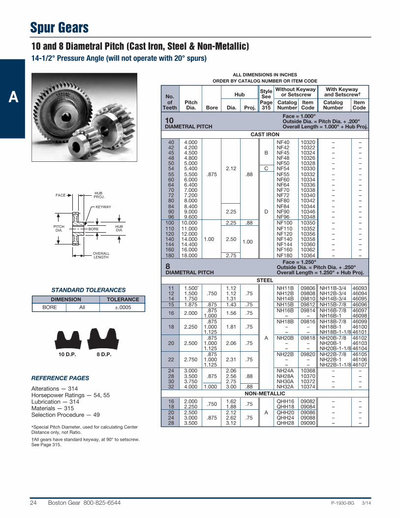
24 Boston Gear 800-825-6544 P-1930-BG 3/14
ALL DIMENSIONS IN INCHESORDER BY CATALOG NUMBER OR ITEM CODE
Style Without Keyway With Keyway No. Hub See or Setscrew and Setscrew†
of Pitch Page Catalog Item Catalog Item Teeth Dia. Bore Dia. Proj. 315 Number Code Number Code
Face = 1.000" 10 Outside Dia. = Pitch Dia. + .200" DIAMETRAL PITCH Overall Length = 1.000" + Hub Proj.
CAST IRON
40 4.000 NF40 10320 – – 42 4.200 NF42 10322 – – 45 4.500 B NF45 10324 – – 48 4.800 NF48 10326 – – 50 5.000 NF50 10328 – – 54 5.400 2.12 C NF54 10330 – – 55 5.500 .875 .88 NF55 10332 – – 60 6.000 NF60 10334 – – 64 6.400 NF64 10336 – – 70 7.000 NF70 10338 – – 72 7.200 NF72 10340 – – 80 8.000 NF80 10342 – – 84 8.400 NF84 10344 – – 90 9.000 2.25 D NF90 10346 – – 96 9.600 NF96 10348 – – 100 10.000 2.25 .88 NF100 10350 – – 110 11.000 NF110 10352 – – 120 12.000 NF120 10356 – – 140 14.000 1.00 2.50 NF140 10358 – – 144 14.400 1.00 NF144 10360 – – 160 16.000 NF160 10362 – – 180 18.000 2.75 NF180 10364 – – Face = 1.250" 8 Outside Dia. = Pitch Dia. + .250" DIAMETRAL PITCH Overall Length = 1.250" + Hub Proj.
STEEL
11 1.500* 1.12 NH11B 09806 NH11B-3/4 46093 12 1.500 .750 1.12 .75 NH12B 09808 NH12B-3/4 46094 14 1.750 1.31 NH14B 09810 NH14B-3/4 46095 15 1.875 .875 1.43 .75 NH15B 09812 NH15B-7/8 46096 16 2.000 .875 1.56 .75 NH16B 09814 NH16B-7/8 46097 1.000 – – NH16B-1 46098 .875 NH18B 09816 NH18B-7/8 46099 18 2.250 1.000 1.81 .75 – – NH18B-1 46100 1.125 – – NH18B-1-1/8 46101 .875 A NH20B 09818 NH20B-7/8 46102 20 2.500 1.000 2.06 .75 – – NH20B-1 46103 1.125 – – NH20B-1-1/8 46104 .875 NH22B 09820 NH22B-7/8 46105 22 2.750 1.000 2.31 .75 – – NH22B-1 46106 1.125 – – NH22B-1-1/8 46107 24 3.000 2.06 NH24A 10368 – – 28 3.500 .875 2.56 .88 NH28A 10370 – – 30 3.750 2.75 NH30A 10372 – – 32 4.000 1.000 3.00 .88 NH32A 10374 – –
NON-METALLIC
16 2.000 .750 1.62 .75 QHH16 09082 – – 18 2.250 1.88 QHH18 09084 – – 20 2.500 2.12 A QHH20 09086 – – 24 3.000 .875 2.62 .75 QHH24 09088 – – 28 3.500 3.12 QHH28 09090 – –
10 and 8 Diametral Pitch (Cast Iron, Steel & Non-Metallic)14-1/2° Pressure Angle (will not operate with 20° spurs)
STANDARD TOLERANCES
DIMENSION TOLERANCE
BORE All ±.0005
REFERENCE PAGES
Alterations — 314Horsepower Ratings — 54, 55Lubrication — 314Materials — 315Selection Procedure — 49
*Special Pitch Diameter, used for calculating CenterDistance only, not Ratio.
†All gears have standard keyway, at 90° to setscrew.See Page 315.
BORE HUBDIA.
HUBPROJ.FACE
PITCHDIA.
OVERALLLENGTH
KEYWAY
10 D.P. 8 D.P.
A

Spur Gears
P-1930-BG 3/14 Boston Gear 800-825-6544 25
8 D.P. 6 D.P.
BORE HUBDIA.
HUBPROJ.FACE
PITCHDIA.
OVERALLLENGTH
8 and 6 Diametral Pitch (Cast Iron & Steel)14-1/2° Pressure Angle (will not operate with 20° spurs)
STANDARD TOLERANCES
DIMENSION TOLERANCE
BORE All ±.0005
REFERENCE PAGES
Alterations — 314Horsepower Ratings — 55, 56Lubrication — 314Materials — 315Selection Procedure — 49
*Special Pitch Diameter, used for calculating CenterDistance only, not Ratio.
†All gears have standard keyway, at 90° to setscrew.See Page 315.
ALL DIMENSIONS IN INCHESORDER BY CATALOG NUMBER OR ITEM CODE
Style Without Keyway With Keyway No. Hub See or Setscrew and Setscrew†
of Pitch Page Catalog Item Catalog Item Teeth Dia. Bore Dia. Proj. 315 Number Code Number Code
Face = 1.250" 8 Outside Dia. = Pitch Dia. + .250" DIAMETRAL PITCH Overall Length = 1.250" + Hub Proj.
CAST IRON
36 4.500 NH36 10376 – – 40 5.000 NH40 10378 – – 42 5.250 B NH42 10380 – – 44 5.500 NH44 10382 – – 48 6.000 1.000 2.50 1.00 NH48 10384 – – 54 6.750 C NH54 10386 – – 56 7.000 NH56 10388 – – 60 7.500 NH60 10390 – – 64 8.000 NH64 10392 – – 72 9.000 NH72 10394 – – 80 10.000 NH80 10396 – – 84 10.500 NH84 10398 – – 88 11.000 D NH88 10400 – – 96 12.000 1.125 3.00 1.12 NH96 10402 – – 112 14.000 NH112 10404 – – 120 15.000 NH120 10406 – – 128 16.000 NH128 10408 – – 144 18.000 NH144 10410 – – 160 20.000 1.125 3.25 1.25 NH160B 10412 – – Face = 1.500" 6 Outside Dia. = Pitch Dia + .333" DIAMETRAL PITCH Overall Length = 1.500" + Hub Proj.
STEEL
11 2.000* 1.000 1.46 .88 NJ11B 09830 NJ11B-1 46108 12 2.000 NJ12B 09832 NJ12B-1 46109 14 2.333 1.000 1.79 .88 NJ14B 09834 NJ14B-1 46110 1.125 – – NJ14B-1-1/8 46111 1.000 NJ15B 09836 NJ15B-1 46112 15 2.500 1.125 1.96 .88 – – NJ15B-1-1/8 46113 1.1875 – – NJ15B-1-3/1646114 1.250 – – NJ15B-1-1/4 46115 1.000 NJ16B 09838 NJ16B-1 46116 16 2.667 1.125 2.13 .88 – – NJ16B-1-1/8 46117 1.1875 A – – NJ16B-1-3/1646118 1.250 – – NJ16B-1-1/4 46119 1.000 NJ18B 09840 NJ18B-1 46120 18 3.000 1.125 2.46 .88 – – NJ18B-1-1/8 46121 1.1875 – – NJ18B-1-3/1646122 1.250 – – NJ18B-1-1/4 46123 1.000 NJ20 09842 NJ20-1 46124 20 3.333 1.125 2.79 .88 – – NJ20-1-1/8 46125 1.1875 – – NJ20-1-3/16 46126 1.250 – – NJ20-1-1/4 46127 21 3.500 1.000 2.96 .88 NJ21B 09844 – – 24 4.000 3.00 NJ24A 10414 – – 27 4.500 1.125 3.50 .88 NJ27A 10416 – – 30 5.000 4.00 NJ30A 10418 – –
A

Spur Gears
26 Boston Gear 800-825-6544 P-1930-BG 3/14
ALL DIMENSIONS IN INCHESORDER BY CATALOG NUMBER OR ITEM CODE
Style Without Keyway No. Hub See or Setscrew
of Pitch Page Catalog Item Teeth Dia. Bore Dia. Proj. 315 Number Code
Face = 1.500˝ 6 Outside Dia. = Pitch Dia + .333˝ DIAMETRAL PITCH Overall Length = 1.500˝ + Hub Proj.
CAST IRON
32 5.333 NJ32 10420 33 5.500 B NJ33 10422 36 6.000 NJ36 10424 40 6.667 1.125 2.50 1.00 C NJ40 10426 42 7.000 NJ42 10428 48 8.000 NJ48 10430 54 9.000 NJ54 10432 60 10.000 NJ60 10434 64 10.667 3.00 NJ64 10436 66 11.000 NJ66 10438 72 12.000 1.25 D NJ72 10440 84 14.000 1.250 NJ84 10442 96 16.000 3.25 NJ96 10444 108 18.000 NJ108 10446 120 20.000 3.50 1.50 NJ120B 10448 144 24.000 3.75 NJ144B 10452 Face = 1.750" 5 Outside Dia. = Pitch Dia. + .400" DIAMETRAL PITCH Overall Length = 1.750" + Hub Proj.
STEEL
11 2.400* 1.78 NK11B 09846 12 2.400 1.78 NK12B 09848 14 2.800 2.18 NK14B 09850 15 3.000 1.0625 2.38 .88 A NK15B 09852 16 3.200 2.58 NK16B 09854 18 3.600 2.98 NK18B 09856 20 4.000 3.38 NK20B 09858
CAST IRON
24 4.800 A NK24B 10454 25 5.000 1.0625 3.00 1.25 NK25B 10456 30 6.000 NK30B 10458 35 7.000 B NK35B 10460 40 8.000 1.1875 3.00 1.25 NK40B 10462 45 9.000 NK45B 10464 50 10.000 NK50B 10466 55 11.000 NK55B 10468 60 12.000 1.1875 3.50 1.25 D NK60B 10470 70 14.000 NK70B 10472 80 16.000 NK80B 10474 100 20.000 1.3125 3.75 1.50 NK100B 10478
*Special Pitch Diameter, used for calculating Center Distance only, not Ratio.
6 and 5 Diametral Pitch (Steel & Cast Iron) 14-1/2° Pressure Angle (will not operate with 20° spurs)
STANDARD TOLERANCES
DIMENSION TOLERANCE
BORE All ±.0005
REFERENCE PAGES
Alterations — 314Horsepower Ratings — 56Lubrication — 314Materials — 315Selection Procedure — 49
6 D.P. 5 D.P.
BORE HUBDIA.
HUBPROJ.FACE
PITCHDIA.
OVERALLLENGTH
A

Spur Gears
P-1930-BG 3/14 Boston Gear 800-825-6544 27
ALL DIMENSIONS IN INCHESORDER BY CATALOG NUMBER OR ITEM CODE
Style Without Keyway No. Hub See or Setscrew
of Pitch Page Catalog Item Teeth Dia. Bore Dia. Proj. 315 Number Code
Face = 2.000" 4 Outside Dia. = Pitch Dia. + .500" DIAMETRAL PITCH Overall Length = 2.000" + Hub Proj.
STEEL
11 3.000* 2.27 NL11B 09860 12 3.000 2.27 NL12B 09862 14 3.500 2.77 NL14B 09864 15 3.750 1.125 3.02 .88 A NL15B 09866 16 4.000 3.27 NL16B 09868 18 4.500 3.77 NL18B 09870 20 5.000 4.27 NL20B 09872 22 5.500 4.77 NL22B 09874
CAST IRON
24 6.000 1.125 A NL24B 10484 28 7.000 NL28B 10486 30 7.500 3.50 B NL30 10488 32 8.000 NL32B 10490 36 9.000 NL36B 10492 40 10.000 NL40B 10494 42 10.500 C NL42 10496 44 11.000 1.250 1.50 NL44B 10498 48 12.000 NL48B 10500 54 13.500 4.00 NL54 10502 56 14.000 NL56B 10504 60 15.000 NL60 10506 64 16.000 D NL64B 10508 72 18.000 NL72B 10510 80 20.000 1.50 NL80B 10512 84 21.000 1.375 4.50 NL84 10514 88 22.000 1.75 NL88B 10516 96 24.000 NL96B 10518 Face = 3.000"† 3 Outside Dia. = Pitch Dia. + .667" DIAMETRAL PITCH Overall Length = Face + Hub Proj.
STEEL
11 4.000* NO11B† 09876 12 4.000 NO12B† 09878 14 4.667 NO14B 09880 15 5.000 1.3125 – – A NO15B 09882 16 5.333 NO16B 09884 18 6.000 NO18B 09886 20 6.667 NO20 09888 21 7.000 NO21B 09890
CAST IRON
24 8.000 4.50 1.25 NO24B 10524 30 10.000 1.4375 B NO30B 10526 36 12.000 5.25 1.75 NO36B 10528 42 14.000 C NO42 10530 48 16.000 NO48B 10532 54 18.000 1.5625 5.25 1.75 NO54 10534 60 20.000 NO60B 10536 72 24.000 1.6875 5.50 1.75 D NO72B 10538 84 28.000 5.75 NO84B 10540 96 32.000 1.9375 5.75 1.75 NO96B 10542 108 36.000 NO108B 10544
*Special Pitch Diameter, used for calculating Center Distance only, not Ratio.†NO11B and NO12B have 4" Face.
4 and 3 Diametral Pitch (Steel & Cast Iron)14-1/2° Pressure Angle (will not operate with 20° spurs)
STANDARD TOLERANCES
DIMENSION TOLERANCE
BORE All ±.0005
REFERENCE PAGES
Alterations — 314Horsepower Ratings — 56, 57Lubrication — 314Materials — 315Selection Procedure — 49
BORE HUBDIA.
HUBPROJ.FACE
PITCHDIA.
OVERALLLENGTH
4 D.P. 3 D.P.
A

Change Gears
28 Boston Gear 800-825-6544 P-1930-BG 3/14
No. of Pitch Hub Catalog Item Teeth Dia. Dia. Number Code
No. of Pitch Hub Catalog Item Teeth Dia. Dia. Number Code
STEEL
20 1.000 GA20 10038 21 1.050 GA21 10040 22 1.100 GA22 10042 23 1.150 GA23 10044 24 1.200 GA24 10046 25 1.250 GA25 10048 26 1.300 GA26 10050 27 1.350 GA27 10052 28 1.400 GA28 10054 29 1.450 GA29 10056 30 1.500 GA30 10058 31 1.550 GA31 10060 32 1.600 GA32 10062 33 1.650 GA33 10064 34 1.700 – GA34 10066 35 1.750 GA35 10068 36 1.800 GA36 10070 37 1.850 GA37 10072 38 1.900 GA38 10074 39 1.950 GA39 10076 40 2.000 GA40 10078 41 2.050 GA41 10080 42 2.100 GA42 10082 43 2.150 GA43 10084 44 2.200 GA44 10086 45 2.250 GA45 10088 46 2.300 GA46 10090 47 2.350 GA47 10092 48 2.400 GA48 10094 49 2.450 GA49 10096 50 2.500 GA50 10098
CAST IRON
51 2.550 GA51B 10802 52 2.600 GA52B 10804 53 2.650 GA53B 10806 54 2.700 GA54B 10808 55 2.750 GA55B 10810 56 2.800 GA56B 10812 57 2.850 GA57B 10814 58 2.900 1.38 GA58B 10816 59 2.950 GA59B 10818 60 3.000 GA60B 10820 61 3.050 GA61B 10822 62 3.100 GA62B 10824 63 3.150 GA63B 10826 64 3.200 GA64B 10828 65 3.250 GA65B 10830 66 3.300 GA66B 10832 67 3.350 1.56 GA67B 10834 68 3.400 GA68B 10836 69 3.450 GA69B 10838 70 3.500 GA70B 10840
CAST IRON
71 3.550 GA71B 10842 72 3.600 GA72B 10844 73 3.650 GA73B 10846 74 3.700 GA74B 10848 75 3.750 1.56 GA75B 10850 76 3.800 GA76B 10852 77 3.850 GA77B 10854 78 3.900 GA78B 10856 79 3.950 GA79B 10858 80 4.000 GA80B 10860 81 4.050 GA81B 10862 82 4.100 GA82B 10864 83 4.150 GA83B 10866 84 4.200 GA84B 10868 85 4.250 GA85B 10870 86 4.300 GA86B 10872 87 4.350 GA87B 10874 88 4.400 GA88B 10876 89 4.450 GA89B 10878 90 4.500 GA90B 10880 91 4.550 GA91B 10882 92 4.600 GA92B 10884 93 4.650 GA93B 10886 94 4.700 GA94B 10888 95 4.750 GA95B 10890 96 4.800 GA96B 10892 97 4.850 GA97B 10894 98 4.900 1.69 GA98B 10896 99 4.950 GA99B 10898 100 5.000 GA100B 10900 101 5.050 GA101B 10902 102 5.100 GA102B 10904 103 5.150 GA103B 10906 104 5.200 GA104B 10908 105 5.250 GA105B 10910 106 5.300 GA106B 10912 107 5.350 GA107B 10914 108 5.400 GA108B 10916 109 5.450 GA109B 10918 110 5.500 GA110B 10920 111 5.550 GA111B 10922 112 5.600 GA112B 10924 113 5.650 GA113B 10926 114 5.700 GA114B 10928 115 5.750 GA115B 10930 116 5.800 GA116B 10932 117 5.850 GA117B 10934 118 5.900 GA118B 10936 119 5.950 GA119B 10938 120 6.000 GA120B 10940
20 Diametral Pitch (Steel & Cast Iron)14-1/2° Pressure Angle (will not operate with 20° spurs)
REFERENCE PAGES
Alterations — 314Horsepower Ratings — 51Lubrication — 314Materials — 315Selection Procedure — 49
ORDER BY CATALOG NUMBEROR ITEM CODE
CATALOG NO. ITEM CODE
GAB20A 18500
COMPOUNDSTEEL BUSHINGSThese steel bushings have 2 keys, 180°apart and fit bores of GA series changegears with a slip fit. They are used tomount two gears on one shaft (or stud)and drive one from the other.
Style 20 – 78 Teeth – A See Page 79 – 120 Teeth – C 315
HUBDIA.
.375 FACE
PITCHDIA. .625 BORE
(2) × KEYWAYS180° APART
18
116
.625
.4370
.4380
.750
.737
.733
.125
20 D.P.
20 DIAMETRAL PITCH Outside Dia. = Pitch Dia. +.100"
A
Change Gears
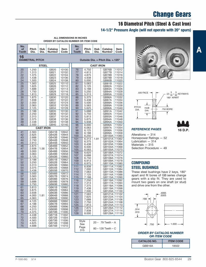
P-1930-BG 3/14 Boston Gear 800-825-6544 29
No. of Pitch Hub Catalog Item Teeth Dia. Dia. Number Code
No. of Pitch Hub Catalog Item Teeth Dia. Dia. Number Code
STEEL
20 1.250 GB20 10100 21 1.313 GB21 10102 22 1.375 GB22 10104 23 1.438 GB23 10106 24 1.500 GB24 10108 25 1.563 GB25 10110 26 1.625 GB26 10112 27 1.688 GB27 10114 28 1.750 GB28 10116 29 1.813 GB29 10118 30 1.875 – GB30 10120 31 1.938 GB31 10122 32 2.000 GB32 10124 33 2.063 GB33 10126 34 2.125 GB34 10128 35 2.188 GB35 10130 36 2.250 GB36 10132 37 2.313 GB37 10134 38 2.375 GB38 10136 39 2.438 GB39 10138 40 2.500 GB40 10140
CAST IRON
41 2.563 GB41B 10942 42 2.625 GB42B 10944 43 2.688 GB43B 10946 44 2.750 GB44B 10948 45 2.913 GB45B 10950 46 2.875 GB46B 10952 47 2.938 1.56 GB47B 10954 48 3.000 GB48B 10956 49 3.063 GB49B 10958 50 3.125 GB50B 10960 51 3.188 GB51B 10962 52 3.250 GB52B 10964 53 3.313 GB53B 10966 54 3.375 GB54B 10968 55 3.438 GB55B 10970 56 3.500 GB56B 10972 57 3.563 GB57B 10974 58 3.625 GB58B 10976 59 3.688 GB59B 10978 60 3.750 GB60B 10980 61 3.813 GB61B 10982 62 3.875 GB62B 10984 63 3.938 GB63B 10986 64 4.000 1.81 GB64B 10988 65 4.063 GB65B 10990 66 4.125 GB66B 10992 67 4.188 GB67B 10994 68 4.250 GB68B 10996 69 4.313 GB69B 10998 70 4.375 GB70B 11000 71 4.438 GB71B 11002 72 4.500 GB72B 11004 73 4.563 GB73B 11006 74 4.625 GB74B 11008 75 4.688 GB75B 11010
CAST IRON
76 4.750 GB76B 11012 77 4.813 GB77B 11014 78 4.875 GB78B 11016 79 4.938 GB79B 11018 80 5.000 GB80B 11020 81 5.063 GB81B 11022 82 5.125 GB82A 11024 83 5.188 GB83A 11026 84 5.250 GB84A 11028 85 5.313 GB85A 11030 86 5.375 GB86A 11032 87 5.438 GB87A 11034 88 5.500 GB88A 11036 89 5.563 GB89A 11038 90 5.625 GB90A 11040 91 5.688 GB91A 11042 92 5.750 GB92A 11044 93 5.813 GB93A 11046 94 5.875 GB94A 11048 95 5.938 GB95A 11050 96 6.000 GB96A 11052 97 6.063 GB97A 11054 98 6.125 GB98A 11056 99 6.188 GB99A 11058 100 6.250 GB100A 11060 101 6.313 1.81 GB101A 11062 102 6.375 GB102A 11064 103 6.438 GB103A 11066 104 6.500 GB104A 11068 105 6.563 GB105A 11070 106 6.625 GB106A 11072 107 6.688 GB107A 11074 108 6.750 GB108A 11076 109 6.913 GB109A 11078 110 6.975 GB110A 11080 111 6.938 GB111A 11082 112 7.000 GB112A 11084 113 7.063 GB113A 11086 114 7.125 GB114A 11088 115 7.188 GB115A 11090 116 7.250 GB116A 11092 117 7.313 GB117A 11094 118 7.375 GB118A 11096 119 7.438 GB119A 11098 120 7.500 GB120A 11100 121 7.563 GB121A 11102 122 7.625 GB122A 11104 123 7.688 GB123A 11106 124 7.750 GB124A 11108 125 7.813 GB125A 11110 126 7.875 GB126A 11112 127 7.938 GB127A 11114 128 8.000 GB128A 11116
16 Diametral Pitch (Steel & Cast Iron)14-1/2° Pressure Angle (will not operate with 20° spurs)
ALL DIMENSIONS IN INCHESORDER BY CATALOG NUMBER OR ITEM CODE
Style 20 – 79 Teeth – A See Page 80 – 128 Teeth – C 315
16 DIAMETRAL PITCH Outside Dia. = Pitch Dia. +.125"
ORDER BY CATALOG NUMBEROR ITEM CODE
CATALOG NO. ITEM CODE
GBB16A 18502
REFERENCE PAGES
Alterations — 314Horsepower Ratings — 52Lubrication — 314Materials — 315Selection Procedure — 49
COMPOUNDSTEEL BUSHINGSThese steel bushings have 2 keys, 180°apart and fit bores of GB series changegears with a slip fit. They are used tomount two gears on one shaft (or stud)and drive one from the other.
HUBDIA.
.500 FACE
PITCHDIA. .750 BORE
(2) 136 × 3
32 KEYWAYS
180° APART
1.000.750
.4995
.5005
.914
.910
.188
16 D.P.
A

Change Gears
30 Boston Gear 800-825-6544 P-1930-BG 3/14
No. of Pitch Hub Catalog Item Teeth Dia. Dia. Number Code
No. of Pitch Hub Catalog Item Teeth Dia. Dia. Number Code
STEEL
20 1.667 GD20 10142 21 1.750 GD21 10144 22 1.833 GD22 10146 23 1.917 GD23 10148 24 2.000 GD24 10150 25 2.083 GD25 10152 26 2.167 GD26 10154 27 2.250 GD27 10156 28 2.333 – GD28 10158 29 2.417 GD29 10160 30 2.500 GD30 10162 31 2.583 GD31 10164 32 2.667 GD32 10166 33 2.750 GD33 10168 34 2.833 GD34 10170 35 2.917 GD35 10172 36 3.000 GD36 10174
CAST IRON
37 3.083 GD37A 11118 38 3.167 GD38A 11120 39 3.250 GD39A 11122 40 3.333 GD40A 11124 41 3.417 GD41A 11126 42 3.500 1.76 GD42A 11128 43 3.583 GD43A 11130 44 3.667 GD44A 11132 45 3.750 GD45A 11134 46 3.833 GD46A 11136 47 3.917 GD47A 11138 48 4.000 GD48A 11140 49 4.083 GD49A 11142 50 4.167 GD50A 11144 51 4.250 GD51A 11146 52 4.333 GD52A 11148 53 4.417 GD53A 11150 54 4.500 GD54A 11152 55 4.583 GD55A 11154 56 4.667 GD56A 11156 57 4.750 GD57A 11158 58 4.833 GD58A 11160 59 4.917 GD59A 11162 60 5.000 GD60A 11164 61 5.083 2.19 GD61A 11166 62 5.167 GD62A 11168 63 5.250 GD63A 11170 64 5.333 GD64A 11172 65 5.417 GD65A 11174 66 5.500 GD66A 11176 67 5.583 GD67A 11178 68 5.667 GD68A 11180 69 5.750 GD69A 11182 70 5.833 GD70A 11184 71 5.917 GD71A 11186 72 6.000 GD72A 11188 73 6.083 GD73A 11190 74 6.167 GD74A 11192
CAST IRON
75 6.250 GD75A 11194 76 6.333 GD76A 11196 77 6.417 GD77A 11198 78 6.500 GD78A 11200 79 6.583 2.19 GD79A 11202 80 6.667 GD80A 11204 81 6.750 GD81A 11206 82 6.833 GD82A 11208 83 6.917 GD83A 11210 84 7.000 GD84A 11212 85 7.083 GD85A 11214 86 7.167 GD86A 11216 87 7.250 GD87A 11218 88 7.333 GD88A 11220 89 7.417 GD89A 11222 90 7.500 GD90A 11224 91 7.583 GD91A 11226 92 7.667 GD92A 11228 93 7.750 GD93A 11230 94 7.833 GD94A 11232 95 7.917 GD95A 11234 96 8.000 GD96A 11236 97 8.083 GD97A 11238 98 8.167 GD98A 11240 99 8.250 GD99A 11242 100 8.333 2.44 GD100A 11244 101 8.417 GD101A 11246 102 8.500 GD102A 11248 103 8.583 GD103A 11250 104 8.667 GD104A 11252 105 8.750 GD105A 11254 106 8.833 GD106A 11256 107 8.917 GD107A 11258 108 9.000 GD108A 11260 109 9.083 GD109A 11262 110 9.167 GD110A 11264 111 9.250 GD111A 11266 112 9.333 GD112A 11268 113 9.417 GD113A 11270 114 9.500 GD114A 11272 115 9.583 GD115A 11274 116 9.667 GD116A 11276 117 9.750 GD117A 11278 118 9.833 GD118A 11280 119 9.917 GD119A 11282 120 10.000 GD120A 11284
12 Diametral Pitch (Steel & Cast Iron)14-1/2° Pressure Angle (will not operate with 20° spurs)
REFERENCE PAGES
Alterations — 314Horsepower Ratings — 53Lubrication — 314Materials — 315Selection Procedure — 49
ORDER BY CATALOG NUMBEROR ITEM CODE
CATALOG NO. ITEM CODE
GDB12A 18504
CompoundSteel BushingsThese steel bushings have 2 keys, 180°apart and fit bores of GD series changegears with a slip fit. They are used tomount two gears on one shaft (or stud)and drive one from the other.
ALL DIMENSIONS IN INCHESORDER BY CATALOG NUMBER OR ITEM CODE
Style 20 – 60 Teeth – A See Page 61 – 120 Teeth – C 315
HUBDIA.
.750 FACE
PITCHDIA. 1.000 BORE
(2) 1–4 × 1–8 KEYWAYS180° APART
1.501.000
.7495
.7505
1.2171.213
.250
12 D.P.
12 DIAMETRAL PITCH Outside Dia. = Pitch Dia. +.167"
A

P-1930-BG 3/14 Boston Gear 800-825-6544 31
No. of Pitch Hub Catalog Item Teeth Dia. Dia. Number Code
No. of Pitch Hub Catalog Item Teeth Dia. Dia. Number Code
STEEL
20 2.000 GF20 10176 21 2.100 GF21 10178 22 2.200 GF22 10180 23 2.300 GF23 10182 24 2.400 GF24 10184 25 2.500 – GF25 10186 26 2.600 GF26 10188 27 2.700 GF27 10190 28 2.800 GF28 10192 29 2.900 GF29 10194 30 3.000 GF30 10196
CAST IRON
31 3.100 GF31B 11286 32 3.200 GF32B 11288 33 3.300 GF33B 11290 34 3.400 GF34B 11292 35 3.500 GF35B 11294 36 3.600 1.94 GF36B 11296 37 3.700 GF37B 11298 38 3.800 GF38B 11300 39 3.900 GF39B 11302 40 4.000 GF40B 11304 41 4.100 GF41B 11306 42 4.200 GF42B 11308 43 4.300 GF43B 11310 44 4.400 GF44B 11312 45 4.500 GF45B 11314 46 4.600 GF46B 11316 47 4.700 GF47B 11318 48 4.800 2.68 GF48B 11320 49 4.900 GF49B 11322 50 5.000 GF50B 11324 51 5.100 GF51B 11326 52 5.200 GF52A 11328 53 5.300 GF53A 11330 54 5.400 GF54A 11332 55 5.500 GF55A 11334 56 5.600 GF56A 11336 57 5.700 GF57A 11338 58 5.800 3.12 GF58A 11340 59 5.900 GF59A 11342 60 6.000 GF60A 11344
CAST IRON
61 6.100 GF61A 11346 62 6.200 GF62A 11348 63 6.300 GF63A 11350 64 6.400 GF64A 11352 65 6.500 GF65A 11354 66 6.600 GF66A 11356 67 6.700 GF67A 11358 68 6.800 GF68A 11360 69 6.900 GF69A 11362 70 7.000 GF70A 11364 71 7.100 GF71A 11366 72 7.200 GF72A 11368 73 7.300 GF73A 11370 74 7.400 GF74A 11372 75 7.500 GF75A 11374 76 7.600 GF76A 11376 77 7.700 GF77A 11378 78 7.800 GF78A 11380 79 7.900 GF79A 11382 80 8.000 GF80A 11384 81 8.100 3.12 GF81A 11386 82 8.200 GF82A 11388 83 8.300 GF83A 11390 84 8.400 GF84A 11392 85 8.500 GF85A 11394 86 8.600 GF86A 11396 87 8.700 GF87A 11398 88 8.800 GF88A 11400 89 8.900 GF89A 11402 90 9.000 GF90A 11404 91 9.100 GF91A 11406 92 9.200 GF92A 11408 93 9.300 GF93A 11410 94 9.400 GF94A 11412 95 9.500 GF95A 11414 96 9.600 GF96A 11416 97 9.700 GF97A 11418 98 9.800 GF98A 11420 99 9.900 GF99A 11422
100 10.000 GF100A 11424
ALL DIMENSIONS IN INCHESORDER BY CATALOG NUMBER OR ITEM CODE
Style 20 – 60 Teeth – A See 61 – 66 Teeth – B Page 67 – 100 Teeth – C 315
10 DIAMETRAL PITCH Outside Dia. = Pitch Dia. +.200"
Change Gears10 Diametral Pitch (Steel & Cast Iron)
14-1/2° Pressure Angle (will not operate with 20° spurs)
ORDER BY CATALOG NUMBEROR ITEM CODE
CATALOG NO. ITEM CODE
GFB10A 18506
REFERENCE PAGES
Alterations — 314Horsepower Ratings — 54Lubrication — 314Materials — 315Selection Procedure — 49
CompoundSteel BushingsThese steel bushings have 2 keys, 180°apart and fit bores of GF series changegears with a slip fit. They are used tomount two gears on one shaft (or stud)and drive one from the other.
HUBDIA.
1.000" FACE
PITCHDIA. 1.250 BORE
(2) 156 × 3
52 KEYWAYS
180° APART
2.0001.250
.99951.0005
1.5231.519
.313
10 D.P.
A

Change Gears
32 Boston Gear 800-825-6544 P-1930-BG 3/14
No. of Pitch Hub Catalog Item Teeth Dia. Dia. Number Code
No. of Pitch Hub Catalog Item Teeth Dia. Dia. Number Code
STEEL
20 2.500 – GH20 10198 21 2.625 – GH21 10200 22 2.750 – GH22 10202 23 2.875 – GH23 10204 24 3.000 – GH24 10206
CAST IRON
25 3.125 GH25B 11426 26 3.250 GH26B 11428 27 3.375 GH27B 11430 28 3.500 GH28B 11432 29 3.625 GH29B 11434 30 3.750 2.06 GH30B 11436 31 3.875 GH31B 11438 32 4.000 GH32B 11440 33 4.125 GH33B 11442 34 4.250 GH34B 11444 35 4.375 GH35B 11446 36 4.500 GH36B 11448 37 4.625 GH37B 11450 38 4.750 GH38B 11452 39 4.875 GH39B 11454 40 5.000 GH40B 11456 41 5.125 2.69 GH41A 11458 42 5.250 GH42A 11460 43 5.375 GH43A 11462 44 5.500 GH44A 11464 45 5.625 GH45A 11466 46 5.750 GH46A 11468 47 5.875 GH47A 11470 48 6.000 GH48A 11472 49 6.125 GH49A 11474 50 6.250 GH50A 11476 51 6.375 GH51A 11478 52 6.500 3.12 GH52A 11480 53 6.625 GH53A 11482 54 6.750 GH54A 11484 55 6.875 GH55A 11486 56 7.000 GH56A 11488 57 7.125 GH57A 11490 58 7.250 GH58A 11492 59 7.375 3.25 GH59A 11494 60 7.500 GH60A 11496
CAST IRON
61 7.625 GH61A 11498 62 7.750 GH62A 11500 63 7.875 GH63A 11502 64 8.000 GH64A 11504 65 8.125 GH65A 11506 66 8.250 GH66A 11508 67 8.375 GH67A 11510 68 8.500 GH68A 11512 69 8.625 GH69A 11514 70 8.750 3.25 GH70A 11516 71 8.875 GH71A 11518 72 9.000 GH72A 11520 73 9.125 GH73A 11522 74 9.250 GH74A 11524 75 9.375 GH75A 11526 76 9.500 GH76A 11528 77 9.625 GH77A 11530 78 9.750 GH78A 11532 79 9.875 GH79A 11534 80 10.000 GH80A 11536 81 10.125 GH81A 11538 82 10.250 GH82A 11540 83 10.375 GH83A 11542 84 10.500 GH84A 11544 85 10.625 GH85A 11546 86 10.750 GH86A 11548 87 10.875 GH87A 11550 88 11.000 GH88A 11552 89 11.125 3.75 GH89A 11554 90 11.250 GH90A 11556 91 11.375 GH91A 11558 92 11.500 GH92A 11560 93 11.625 GH93A 11562 94 11.750 GH94A 11564 95 11.875 GH95A 11566 96 12.000 GH96A 11568 97 12.125 GH97A 11570 98 12.250 GH98A 11572 99 12.375 GH99A 11574 100 12.500 GH100A 11576
8 Diametral Pitch (Steel & Cast Iron)14-1/2° Pressure Angle (will not operate with 20° spurs)
REFERENCE PAGES
Alterations — 314Horsepower Ratings — 55Lubrication — 314Materials — 315Selection Procedure — 49
ORDER BY CATALOG NUMBEROR ITEM CODE
CATALOG NO. ITEM CODE
GHB8A 18508
CompoundSteel BushingsThese steel bushings have 2 keys, 180°apart and fit bores of GH series changegears with a slip fit. They are used tomount two gears on one shaft (or stud)and drive one from the other.
ALL DIMENSIONS IN INCHESORDER BY CATALOG NUMBER OR ITEM CODE
Style 20 – 49 Teeth – A See 50 – 57 Teeth – B Page 58 – 68 Teeth – C 315 69 – 100 Teeth – D
1.250 FACE
PITCHDIA. HUB
DIA. 1.375 BORE
(2) × KEYWAYS180° APART
38
316
1.12451.1255
.375
1.6981.694
1.375 2.50
8 D.P.
8 DIAMETRAL PITCH Outside Dia. = Pitch Dia. +.250"
A

Stem Pinions
P-1930-BG 3/14 Boston Gear 800-825-6544 33
20 through 6 Diametral Pitch (Steel)14-1/2° Pressure Angle (will not operate with 20° spurs)
STANDARD TOLERANCES
DIMENSION TOLERANCE
STEM DIA. All +.0000 – .0015
OVERALL LENGTH
STEM LENGTHFACE
PITCHDIA
(SPL)
STEMDIA
Boston Gear Stem Pinions feature small numbers of teeth cut integral on a steelshaft. Undercutting of the teeth is minimized by the use of special enlargedPitch Diameters. When run with standard stock spur gears, they provide highratios not normally found in spur gear drives. They are not intended to be oper-ated with each other, with internal gears or with 11 tooth pinions, but will runsatisfactorily with all other standard 141⁄2° Pressure Angle spur gears.
ALL DIMENSIONS IN INCHESORDER BY CATALOG NUMBER OR ITEM CODE
*Used for calculating Center Distance, not ratio.
No. of Pitch Stem Stem Overall Catalog Item Teeth Dia.* Dia. Length Length Number Code
20 DIAMETRAL PITCH FACE = 1.125"
5 .287 .375 2.875 4.500 NAR5 09654 6 .335 .375 2.875 4.500 NAR6 09656 8 .430 .500 3.375 5.000 NAR8 09658 10 .525 .625 3.375 5.000 NAR10 09660
16 DIAMETRAL PITCH FACE = 1.375"
5 .359 .4375 3.125 5.000 NBR5 09696 6 .419 .500 3.125 5.000 NBR6 09698 8 .537 .625 3.375 5.250 NBR8 09700 10 .656 .750 3.375 5.250 NBR10 09702
12 DIAMETRAL PITCH FACE = 2.000"
5 .479 .625 4.375 7.250 NDR5 09734 6 .558 .625 4.375 7.250 NDR6 09736 7 .637 .750 4.375 7.250 NDR7 09738 8 .716 .875 4.375 7.250 NDR8 09740 10 .875 1.000 4.375 7.250 NDR10 09742
10 DIAMETRAL PITCH FACE = 2.250"
5 .575 .750 4.375 7.500 NFR5 09768 6 .670 .750 4.375 7.500 NFR6 09770 7 .765 .875 4.375 7.500 NFR7 09772 8 .860 1.000 4.375 7.500 NFR8 09774 10 1.050 1.125 4.375 7.500 NFR10 09776
8 DIAMETRAL PITCH FACE = 2.500"
5 .718 .875 4.375 7.750 NHR5 09796 6 .837 1.000 4.375 7.750 NHR6 09798 7 .956 1.125 4.375 7.750 NHR7 09800 8 1.075 1.125 4.375 7.750 NHR8 09802 10 1.312 1.500 4.375 7.750 NHR10 09804
6 DIAMETRAL PITCH FACE = 3.000"
5 .958 1.250 4.375 8.500 NJR5 09822 6 1.116 1.375 4.375 8.500 NJR6 09824 8 1.433 1.625 5.000 9.000 NJR8 09826 10 1.750 2.000 5.375 9.500 NJR10 09828
A

Drawn Pinion Wire
34 Boston Gear 800-825-6544 P-1930-BG 3/14
48, 32 and 24 Diametral Pitch (Brass & Steel)14-1/2° Pressure Angle (will not operate with 20° spurs)
No. of Pitch Catalog Item Teeth Dia. Number Code
48 DIAMETRAL PITCH
BRASS
6 .125 G24 36900 8 .167 G25 36902 9 .188 G26 36904 10 .208 G27 36906 12 .250 G29 36908 14 .292 G30 36910 15 .312 G31 36912 16 .333 G32 36914 18 .375 G33 36916
STEEL
6 .125 GS24 36954 8 .167 GS25 36956 9 .188 GS26 36958 10 .208 GS27 36960 12 .250 GS29 36962 14 .292 GS30 36964 15 .312 GS31 36966 16 .333 GS32 36968 18 .375 GS33 36970
32 DIAMETRAL PITCH
BRASS
6 .188 G39 36918 8 .250 G40 36920 9 .281 G41 36922 10 .312 G42 36924 11 .344 G43 36926 12 .375 G44 36928 14 .438 G45 36930 15 .469 G46 36932 16 .500 G47 36934
STEEL
6 .188 GS39 36972 8 .250 GS40 36974 9 .281 GS41 36976 10 .312 GS42 36978 11 .344 GS43 36980 12 .375 GS44 36982 14 .438 GS45 36984 15 .469 GS46 36986 16 .500 GS47 36988
24 DIAMETRAL PITCH
BRASS
6 .250 G54 36936 9 .375 G56 36940 10 .417 G57 36942 12 .500 G59 36946 14 .583 G60 36948 15 .625 G61 36950 16 .667 G62 36952
STEEL
6 .250 GS54 36990 8 .333 GS55 36992 9 .375 GS56 36994 10 .417 GS57 36996 11 .458 GS58 36998 12 .500 GS59 37000 14 .583 GS60 37002 15 .625 GS61 37004 16 .667 GS62 37006
Drawn Pinion Wire, teeth not generated.All Pinion Wire is stocked in 4 footpieces. Other lengths can be furnishedon special order. Price on application.
ORDER BY CATALOG NUMBER OR ITEM CODE
A

Rack
P-1930-BG 3/14 Boston Gear 800-825-6544 35
ALL DIMENSIONS IN INCHESORDER BY CATALOG NUMBER OR ITEM CODE
*Face Width of L512-4 and L512-6 = 1/2".
Pitch Nom- Mating Nylon SteelOverall Line inal Spur Thick- to Back Length Gear Catalog Item Catalog Item ness (B) (Feet) Page # Number Code Number Code 48 DIAMETRAL PITCH FACE WIDTH = .125"
.125 .104 1 18 GP586-1 53899 – – 2 – – L501-2 12726 32 DIAMETRAL PITCH FACE WIDTH = .188"
1 GP583-1 53900 – – .188 .156 2 18, 19 – – L503-2 12728 4 – – L503-4 12730 24 DIAMETRAL PITCH FACE WIDTH = .250"
1 GP579-1 53901 – – .250 .208 2 19, 20 – – L505-2 12732 4 – – L505-4 12734 20 DIAMETRAL PITCH FACE WIDTH = .375"
2 – – L509-2 12736 .375 .325 4 20, 21 – – L509-4 12738 6 – – L509-6 12740 16 DIAMETRAL PITCH *FACE WIDTH = .313"
.312 .250 2 – – L510-2 12742 4 21, 22 – – L510-4 12744 .500 .438 4 – – L512-4 12746 6 – – L512-6 12748 12 DIAMETRAL PITCH FACE WIDTH = .750"
.500 .417 4 – – L514-4 12750 6 22, 23 – – L514-6 12752 .750 .667 4 – – L515-4 12754 6 – – L515-6 12756 10 DIAMETRAL PITCH FACE WIDTH = 1.000"
.625 .525 4 – – L516-4 37324 6 23, 24 – – L516-6 37326 1.000 .900 4 – – L517-4 37328 6 – – L517-6 37330 8 DIAMETRAL PITCH FACE WIDTH = 1.250"
.750 .625 4 – – L518-4 37332 6 24, 25 – – L518-6 37334 1.250 1.125 4 – – L519-4 37336 6 – – L519-6 37338 6 DIAMETRAL PITCH FACE WIDTH = 1.500"
1.000 .833 4 – – L520-4 37340 6 25, 26 – – L520-6 37342 1.500 1.333 4 – – L521-4 37344 6 – – L521-6 37346 5 DIAMETRAL PITCH FACE WIDTH = 1.750"
1.250 1.050 4 26 – – L522-4 37348 6 – – L522-6 37350 4 DIAMETRAL PITCH FACE WIDTH = 2.000"
1.500 1.250 4 27 – – L523-4 37352 6 – – L523-6 37354 3 DIAMETRAL PITCH FACE WIDTH = 3.000"
1.500 1.167 4 27 – – L524-4 37356 6 – – L524-6 37358
48 through 3 Diametral Pitch (Nylon & Steel)14-1/2° Pressure Angle (will not operate with 20° spurs)
REFERENCE PAGES
Alterations — 314Lubrication — 314Materials — 315
STANDARD TOLERANCES ‡
DIMENSION TOLERANCE
LENGTH† All + 1.00 – .000 1/8 – 3/4 + .000 – .002 FACE 1 – 1-1/2 + .000 – .003 WIDTH 1-3/4 – 2 + .000 – .004 3 + .000 – .006
†Ends not machined. Tolerance allows for cutting andmatching. Nylon Rack is molded in proper lengths topermit end to end butting without interruption of toothspacing.‡Steel only.
WIDTH
OVERALLTHICKNESS
LENGTH
PITCH LINETO BACK
(B)
D2
FACEWIDTH
OVERALLTHICKNESS
LENGTH
PITCH DIAOF GEAR
(D)
PITCH LINETO BACK
(B)
GEARCENTER LINE
TO BACK OF RACKB +
A

36 Boston Gear 800-825-6544 P-1930-BG 3/14
Internal Gears48 through 16 Diametral Pitch (Brass)14-1/2° Pressure Angle (will not operate with 20° spurs)
ORDER BY CATALOG NUMBER OR ITEM CODE
STANDARD TOLERANCES
DIMENSION TOLERANCE
48 Pitch All +.004 – .000 I.D. 32 Pitch All +.005 – .000 24 Pitch All +.006 – .000 16 Pitch All +.008 – .000 O.D. All +.001 + .003
NOTE: The difference in tooth numbers between Gear and Pinion should not be less than 15.
No. of Pitch Catalog ItemTeeth Dia. O.D. I.D. Number Code
48 DIAMETRAL PITCH FACE = .125"
48 1.000 1.500 .986 G632 12066 72 1.500 2.000 1.486 G633 12068 96 2.000 2.750 1.986 G635 12070 144 3.000 3.750 2.986 G637 12072
32 DIAMETRAL PITCH FACE = .188"
48 1.500 2.000 1.480 G664 12056 64 2.000 2.750 1.980 G666 12058 96 3.000 3.750 2.980 G668 12060 128 4.000 4.750 3.980 G669 12062 192 6.000 6.750 5.980 G670 12064
24 DIAMETRAL PITCH FACE = .250"
36 1.500 2.250 1.474 G675 12046 48 2.000 2.750 1.974 G677 12048 72 3.000 3.750 2.974 G679 12050 96 4.000 4.750 3.974 G680 12052 144 6.000 6.750 5.974 G681 12054
16 DIAMETRAL PITCH FACE = .313"
32 2.000 2.750 1.962 G689 12038 48 3.000 3.750 2.962 G691 12040 64 4.000 4.750 3.962 G692 12042 96 6.000 6.750 5.962 G693 12044
OUTSIDEDIA.INSIDE
DIA.PITCHDIA.
FACE
PINIONPITCH DIA.
(d)
GEARPITCH DIA.
(D)
CENTER DISTANCE
CENTERDISTANCE = D – d
2
A

P-1930-BG 3/14 Boston Gear 800-825-6544 37
ALL DIMENSIONS IN INCHESORDER BY CATALOG NUMBER OR ITEM CODE
Style Without Keyway No. Hub See or Setscrew
of Pitch Page Catalog Item Teeth Dia. Bore Dia. Proj. 315 Number Code
Face = .125" 64 Outside Dia. = Pitch Dia. + .033" DIAMETRAL PITCH Overall Length = .125" + Hub Proj.
BRASS
16 .250 .19 Y6416 09482 18 .281 .22 Y6418 09484 20 .312 .125 .25 .19 Y6420 09486 24 .375 .28 Y6424 09488 28 .438 .34 Y6428 09490 32 .500 .38 Y6432 09492 36 .562 .44 Y6436 09494 40 .625 .44 Y6440 09496 44 .688 .1875 .50 .25 A Y6444 09498 48 .750 .50 Y6448 09500 52 .812 .56 Y6452 09502 56 .875 .56 Y6456 09504 60 .938 .62 Y6460 09506 64 1.000 .62 Y6464 09508 72 1.125 .69 Y6472 09510 80 1.250 .69 Y6480 09512 88 1.375 .250 .75 .25 Y6488 09514 96 1.500 .75 Y6496 09516 112 1.750 .81 Y64112 09518 128 2.000 .88 Y64128 09520 144 2.250 .75 Y64144 09522 160 2.500 .3125 .75 .31 C Y64160 09524 192 3.000 .88 Y64192 09526 Face = .125" 48 Outside Dia. = Pitch Dia. + .042" DIAMETRAL PITCH Overall Length = .125" + Hub Proj.
MOLDED DELRIN
18 .375 .31 YP4818 53902 19 .396 YP4819 53903 20 .417 .34 YP4820 53904 21 .438 YP4821 53905 22 .458 .38 YP4822 53906 23 .479 YP4823 53907 24 .500 .1562 .41 .25 YP4824 53908 25 .521 YP4825 53909 26 .542 .45 YP4826 53910 27 .562 YP4827 53911 28 .583 .48 YP4828 53912 29 .604 YP4829 53913 30 .625 .50 A YP4830 53914 31 .646 YP4831 53915 32 .667 YP4832 53916 33 .688 YP4833 53917 34 .708 YP4834 53918 35 .729 YP4835 53919 36 .750 .1875 .55 .25 YP4836 53920 37 .771 YP4837 53921 38 .792 YP4838 53922 39 .813 YP4839 53923 40 .833 YP4840 53924 42 .875 YP4842 53925
Spur Gears
64 and 48 Diametral Pitch (Delrin & Brass)20° Pressure Angle (will not operate with 14-1⁄2° spurs)
STANDARD TOLERANCES
DIMENSION TOLERANCE
BORE All ±.0005
REFERENCE PAGES
Alterations — 314Lubrication — 314Materials — 315
48 D.P. 64 D.P.
BORE HUBDIA.
HUBPROJ.FACE
PITCHDIA.
OVERALLLENGTH
A

38 Boston Gear 800-825-6544 P-1930-BG 3/14
Spur Gears48 Diametral Pitch (Delrin)20° Pressure Angle (will not operate with 14-1⁄2° spurs)
STANDARD TOLERANCES*
DIMENSION TOLERANCE
BORE All +.001 – .000
*Gears with Brass Inserts only.
REFERENCE PAGES
Alterations — 314Materials — 315
†All YPB gears have setscrews.
48 D.P.
BORE HUBDIA.
HUBPROJ.FACE
PITCHDIA.
OVERALLLENGTH
BORE SETSCREW
1/8 #2-56
3/16 #4-40
1/4 #6-32
ALL DIMENSIONS IN INCHESORDER BY CATALOG NUMBER OR ITEM CODE
Style Without Keyway No. Hub See or Setscrew†
of Pitch Page Catalog Item Teeth Dia. Bore Dia. Proj. 315 Number Code
Face = .125" 48 Outside Dia. = Pitch Dia. + .042" DIAMETRAL PITCH Overall Length = .125" + Hub Proj.
MOLDED DELRIN
44 .917 .188 .55 YP4844 53926 45 .938 YP4845 53927 48 1.000 YP4848 53928 52 1.083 YP4852 53929 54 1.125 YP4854 53930 56 1.168 YP4856 53931 60 1.250 YP4860 53932 64 1.333 .250 .61 .25 B YP4864 53933 66 1.375 YP4866 53934 72 1.500 YP4872 53935 80 1.667 YP4880 53936 84 1.750 YP4884 53937 96 2.000 YP4896 53938 100 2.083 YP48100 53939 108 2.250 YP48108 53940 120 2.500 YP48120 53941
MOLDED DELRIN WITH BRASS INSERTS
18 .375 .31 YPB4818 53942 19 .396 YPB4819 53943 20 .417 .34 YPB4820 53944 21 .438 .125 YPB4821 53945 22 .458 .38 YPB4822 53946 23 .479 YPB4823 53947 24 .500 .40 YPB4824 53948 25 .521 YPB4825 53949 26 .542 .45 YPB4826 53950 27 .562 YPB4827 53951 28 .583 .48 YPB4828 53952 29 .604 YPB4829 53953 30 .625 .50 A YPB4830 53954 31 .646 YPB4831 53955 32 .667 YPB4832 53956 33 .688 YPB4833 53957 34 .708 .188 YPB4834 53958 35 .729 YPB4835 53959 36 .750 YPB4836 53960 37 .771 .55 .25 YPB4837 53961 38 .792 YPB4838 53962 39 .813 YPB4839 53963 40 .833 YPB4840 53964 42 .875 YPB4842 53965 44 .917 YPB4844 53966 45 .938 YPB4845 53967 48 1.000 YPB4848 53968 52 1.083 YPB4852 53969 54 1.125 YPB4854 53970 56 1.168 YPB4856 53971 60 1.250 YPB4860 53972 64 1.333 YPB4864 53973 66 1.375 .250 .61 B YPB4866 53974 72 1.500 YPB4872 53975 80 1.667 YPB4880 53976 84 1.750 YPB4884 53977 96 2.000 YPB4896 53978 100 2.083 YPB48100 53979 108 2.250 YPB48108 53980 120 2.500 YPB48120 53981
A

Spur Gears
P-1930-BG 3/14 Boston Gear 800-825-6544 39
BORE HUBDIA.
HUBPROJ.FACE
PITCHDIA.
OVERALLLENGTH
48 D.P. 32 D.P.
ALL DIMENSIONS IN INCHESORDER BY CATALOG NUMBER OR ITEM CODE
Style Without Keyway No. Hub See or Setscrew
of Pitch Page Catalog Item Teeth Dia. Bore Dia. Proj. 315 Number Code
Face = .125" 48 Outside Dia. = Pitch Dia. + .042" DIAMETRAL PITCH Overall Length = .125" + Hub Proj.
BRASS
12 .250 .18 Y4812 09444 15 .312 .125 .22 .19 Y4815 09446 18 .375 .28 Y4818 09448 21 .438 .35 Y4821 09450 24 .500 .38 Y4824 09452 27 .562 .44 Y4827 09454 30 .625 .1875 .44 .25 Y4830 09456 36 .750 .50 A Y4836 09458 42 .875 .57 Y4842 09460 48 1.000 .63 Y4848 09462 54 1.125 .69 Y4854 09464 60 1.250 .69 Y4860 09466 66 1.375 .250 .75 .25 Y4866 09468 72 1.500 .75 Y4872 09470 84 1.750 .82 Y4884 09472 96 2.000 .88 Y4896 09474 120 2.500 .75 Y48120 09476 144 3.000 .3125 .88 .31 C Y48144 09478 192 4.000 1.00 Y48192 09480 Face = .188" 32 Outside Dia. = Pitch Dia. + .062" DIAMETRAL PITCH Overall Length = .188" + Hub Proj.
MOLDED DELRIN
12 .375 .28 YP3212 53982 14 .438 .31 YP3214 53983 15 .469 .1562 .31 .31 YP3215 53984 16 .500 .34 YP3216 53985 18 .562 YP3218 53986 20 .625 .47 A YP3220 53987 22 .688 .50 YP3222 53988 24 .750 .1875 .31 YP3224 53989 26 .812 .56 YP3226 53990 28 .875 .50 YP3228 53991 30 .938 .56 YP3230 53992 32 1.000 .63 YP3232 53993 34 1.062 YP3234 53994 36 1.125 YP3236 53995 38 1.187 .250 .61 .31 YP3238 53996 40 1.250 YP3240 53997 42 1.312 YP3242 53998 44 1.375 YP3244 53999 48 1.500 .63 B YP3248 54000 52 1.625 YP3252 54001 56 1.750 .67 YP3256 54002 64 2.000 .3125 .31 YP3264 54003 72 2.250 YP3272 54004 80 2.500 .81 YP3280 54005 96 3.000 YP3296 54006
48 and 32 Diametral Pitch (Delrin & Brass)20° Pressure Angle (will not operate with 14-1⁄2° spurs)
STANDARD TOLERANCES*
DIMENSION TOLERANCE
BORE All ±.0005˜*Brass only.
REFERENCE PAGES
Alterations — 314Lubrication — 314Materials — 315
A

Spur Gears
40 Boston Gear 800-825-6544 P-1930-BG 3/14
32 Diametral Pitch (Delrin & Brass)20° Pressure Angle (will not operate with 14-1⁄2° spurs)
STANDARD TOLERANCES
DIMENSION TOLERANCEBrass
BORE All ± .0005 Delrin with Brass Inserts BORE All + .001 – .000
REFERENCE PAGES
Alterations — 314Lubrication — 314Materials — 315
†All YPB gears have setscrew and spot drill.
BORE HUBDIA.
HUBPROJ.FACE
PITCHDIA.
OVERALLLENGTH
32 D.P.
BORE SETSCREW
1/8 #2-56
3/16 #4-40
1/4 #6-32
5/16 #8-32
ALL DIMENSIONS IN INCHESORDER BY CATALOG NUMBER OR ITEM CODE
Style Without Keyway No. Hub See or Setscrew†
of Pitch Page Catalog Item Teeth Dia. Bore Dia. Proj. 315 Number Code
Face = .188" 32 Outside Dia. = Pitch Dia. + .062" DIAMETRAL PITCH Overall Length = .188" + Hub Proj.
MOLDED DELRIN with BRASS INSERTS
12 .375 .28 YPB3212 54007 14 .438 .31 YPB3214 54008 15 .469 .125 .31 YPB3215 54009 16 .500 .34 YPB3216 54010 18 .562 .34 YPB3218 54011 20 .625 .47 A YPB3220 54012 22 .688 .50 YPB3222 54013 24 .750 .1875 .50 YPB3224 54014 26 .812 .56 YPB3226 54015 28 .875 .50 YPB3228 54016 30 .938 .56 YPB3230 54017 32 1.000 .63 .31 YPB3232 54018 34 1.062 .61 YPB3234 54019 36 1.125 .61 YPB3236 54020 38 1.187 .250 .61 YPB3238 54021 40 1.250 .61 YPB3240 54022 42 1.312 .61 YPB3242 54023 44 1.375 .61 B YPB3244 54024 48 1.500 .63 YPB3248 54025 52 1.625 .67 YPB3252 54026 56 1.750 .67 YPB3256 54027 64 2.000 .3125 .67 YPB3264 54028 72 2.250 .81 YPB3272 54029 80 2.500 .81 YPB3280 54030 96 3.000 .81 YPB3296 54031
BRASS
12 .375 .125 .28 .25 Y3212 09406 14 .438 .34 Y3214 09408 16 .500 .40 Y3216 09410 18 .562 .43 Y3218 09412 20 .625 .1875 .47 .25 Y3220 09414 24 .750 .53 Y3224 09416 28 .875 .59 A Y3228 09418 32 1.000 .66 Y3232 09420 36 1.125 .250 .72 .25 Y3236 09422 40 1.250 .72 Y3240 09424 48 1.500 .78 Y3248 09426 56 1.750 .84 .25 Y3256 09428 64 2.000 .90 Y3264 09430 72 2.250 .88 Y3272 09432 80 2.500 .3125 .88 Y3280 09434 96 3.000 1.00 .31 C Y3296 09436 112 3.500 1.00 Y32112 09438 128 4.000 1.00 Y32128 09440 160 5.000 1.00 Y32160 09442
A

Spur Gears
P-1930-BG 3/14 Boston Gear 800-825-6544 41
ALL DIMENSIONS IN INCHESORDER BY CATALOG NUMBER OR ITEM CODE
Style Without Keyway No. Hub See or Setscrew†
of Pitch Page Catalog Item Teeth Dia. Bore Dia. Proj. 315 Number Code
Face = .250" 24 Outside Dia. = Pitch Dia. + .083" DIAMETRAL PITCH Overall Length = .250" + Hub Proj.
MOLDED DELRIN
12 .500 .38 YP2412 54032 14 .583 .44 YP2414 54033 15 .625 .48 YP2415 54034 16 .667 YP2416 54035 17 .709 YP2417 54036 18 .750 .188 A YP2418 54037 19 .791 YP2419 54038 20 .833 .55 YP2420 54039 21 .875 YP2421 54040 22 .917 YP2422 54041 23 .959 YP2423 54042 24 1.000 .63 YP2424 54043 25 1.041 .61 YP2425 54044 26 1.083 YP2426 54045 27 1.125 .63 YP2427 54046 28 1.167 .250 YP2428 54047 30 1.250 .31 YP2430 54048 32 1.333 YP2432 54049 33 1.375 .61 YP2433 54050 34 1.416 YP2434 54051 36 1.500 .63 YP2436 54052 39 1.625 B YP2439 54053 40 1.666 YP2440 54054 42 1.750 YP2442 54055 44 1.833 YP2444 54056 45 1.875 YP2445 54057 48 2.000 .313 .67 YP2448 54058 50 2.083 YP2450 54059 52 2.166 YP2452 54060 54 2.250 YP2454 54061 56 2.333 YP2456 54062 60 2.500 YP2460 54063
MOLDED DELRIN WITH BRASS INSERTS
12 .500 .38 YPB2412 54064 14 .583 .44 YPB2414 54065 15 .625 .48 YPB2415 54066 16 .667 YPB2416 54067 17 .709 YPB2417 54068 18 .750 .188 A YPB2418 54069 19 .791 YPB2419 54070 20 .833 .55 YPB2420 54071 21 .875 YPB2421 54072 22 .917 YPB2422 54073 23 .959 .31 YPB2423 54074 24 1.000 .63 YPB2424 54075 25 1.041 .61 YPB2425 54076 26 1.083 YPB2426 54077 27 1.125 .63 YPB2427 54078 28 1.167 .250 YPB2428 54079 30 1.250 YPB2430 54080 32 1.333 B YPB2432 54081 33 1.375 .61 YPB2433 54082 34 1.416 YPB2434 54083 36 1.500 .63 YPB2436 54084 39 1.625 YPB2439 54085 40 1.666 .313 .67 YPB2440 54086 42 1.750 YPB2442 54087
24 D.P.
BORE HUBDIA.
HUBPROJ.FACE
PITCHDIA.
OVERALLLENGTH
BORE SETSCREW
3/16 #4-40
1/4 #6-32
5/16 #8-32
24 Diametral Pitch (Delrin)20° Pressure Angle (will not operate with 14-1⁄2° spurs)
STANDARD TOLERANCES*
DIMENSION TOLERANCE
BORE All +.001 – .000
*Gears with Brass Inserts only.
REFERENCE PAGES
Alterations — 314Materials — 315
†All YPB gears have setscrew and spot drill.
A

Spur Gears
42 Boston Gear 800-825-6544 P-1930-BG 3/14
24 and 20 Diametral Pitch (Delrin, Brass, Steel & Cast Iron)20° Pressure Angle (will not operate with 14-1⁄2° spurs)
STANDARD TOLERANCES
DIMENSION TOLERANCEBrass, Steel and Cast Iron
BORE All ± .0005 Delrin with Brass Inserts BORE All + .001 – .000
REFERENCE PAGES
Alterations — 314Horsepower Ratings — 58Lubrication — 314Materials — 315Selection Procedure — 49
†YPB gears have one setscrew (#8-32), no keyway.
*5/16" bore have #35 (.110) drilled holethrough one wall, no keyway.‡3/8" bore have one setscrew.No keyway.1/2" bore and larger have standardkeyway at 90° to setscrew.See Page 315.
ALL DIMENSIONS IN INCHESORDER BY CATALOG NUMBER OR ITEM CODE
Style Without Keyway With Keyway No. Hub See or Setscrew and Setscrew†
of Pitch Page Catalog Item Catalog Item Teeth Dia. Bore Dia. Proj. 315 Number Code Number Code
Face = .250" 24 Outside Dia. = Pitch Dia. + .083" DIAMETRAL PITCH Overall Length = .250" + Hub Proj.
MOLDED DELRIN WITH BRASS INSERTS
44 1.833 YPB2444 54088 – – 45 1.875 YPB2445 54089 – – 48 2.000 YPB2448 54090 – – 50 2.083 .3125 .67 .31 B YPB2450 54091 – – 52 2.166 YPB2452 54092 – – 54 2.250 YPB2454 54093 – – 56 2.333 YPB2456 54094 – – 60 2.500 YPB2460 54095 – –
BRASS
12 .500 .38 Y2412 09372 – – 15 .625 .1875 .50 .25 Y2415 09374 – – 18 .750 .54 Y2418 09376 – – 21 .875 .60
A Y2421 09378 – –
24 1.000 .66 Y2424 09380 – – 27 1.125 .250 .73 .25 Y2427 09382 – – 30 1.250 .73 Y2430 09384 – – 36 1.500 .79 Y2436 09386 – – 42 1.750 .86 .25 Y2442 09388 – – 48 2.000 .3125 .92 Y2448 09390 – – 54 2.250 .88 .31 Y2454 09392 – – 60 2.500 .88 Y2460 09394 – – 72 3.000 Y2472 09396 – – 84 3.500 .31 C Y2484 09398 – – 96 4.000 .375 1.00 Y2496 09400 – – 120 5.000 .38 Y24120 09402 – – 144 6.000 Y24144 09404 – – Face = .500" 20 Outside Dia. = Pitch Dia. + .100" DIAMETRAL PITCH Overall Length = .500" + Hub Proj.
STEEL
12 .600 .3125 .46 .44 YA12 09892 YA12-5/16* 46128 14 .700 .56 YA14 09894 YA14-5/16* 46129 15 .750 .60 YA15 09896 YA15-3/8‡ 46130 16 .800 .375 .66 .44 YA16 09898 YA16-3/8‡ 46131 18 .900 .74 YA18 09900 YA18-3/8‡ 46132 20 1.000 .84 YA20 09902 YA20-1/2 46133 24 1.200 .92 .44 YA24 09914 YA24-1/2 46134 25 1.250 .500 .97 A YA25 09904 YA25-1/2 46135 30 1.500 1.22 YA30 09906 YA30-1/2 46136 35 1.750 1.47 .50 YA35 09908 YA35-1/2 46137 .500 YA40 09910 YA40-1/2 46138 40 2.000 .625 1.72 .50 – – YA40-5/8 46139 .750 – – YA40-3/4 46140 45 2.250 1.97 YA45 09912 – – 50 2.500 .500 1.62 .50 YA50A 10548 – – 60 3.000 2.12 YA60A 10550 – – 70 3.500 2.38 YA70A 10552 – –
CAST IRON
80 4.000 C YA80 10554 – – 84 4.200 .625 1.38 .62 B YA84 10556 – – 90 4.500
C YA90 10558 – –
100 5.000 YA100 10560 – – 120 6.000 .625 1.50 .62 YA120 10562 – – 140 7.000 YA140 10564 – – 160 8.000 D YA160 10566 – – 180 9.000 .625 1.75 .75 YA180 10568 – – 200 10.000 YA200 10570 – –
BORE HUBDIA.
HUBPROJ.FACE
PITCHDIA.
OVERALLLENGTH
24 D.P. 20 D.P.
A

Spur Gears
P-1930-BG 3/14 Boston Gear 800-825-6544 43
BORE HUBDIA.
HUBPROJ.FACE
PITCHDIA.
OVERALLLENGTH
16 D.P.
12 D.P.
ALL DIMENSIONS IN INCHESORDER BY CATALOG NUMBER OR ITEM CODE
Style Without Keyway With Keyway No. Hub See or Setscrew and Setscrew†
of Pitch Page Catalog Item Catalog Item Teeth Dia. Bore Dia. Proj. 315 Number Code Number Code
Face = .750" 16 Outside Dia. = Pitch Dia. + .125" DIAMETRAL PITCH Overall Length = .750" + Hub Proj.
STEEL
12 .750 .375 .56 .50 YB12 09916 YB12-3/8† 46141 14 .875 .69 YB14 09918 YB14-3/8† 46142 15 .938 .375 .75 .50 YB15 09920 YB15-3/8† 45991 .500 – – YB15-1/2 46143 16 1.000 .500 .81 .50 YB16 09922 YB16-1/2 46144 18 1.125 .94 YB18 09924 YB18-1/2 46145 20 1.250 .625 1.05 .50 YB20 09926 YB20-5/8 46146 24 1.500 .625 1.20 .50 YB24 09928 YB24-5/8 46147 .750 – – YB24-3/4 46148 28 1.750 .625 1.45 .50 YB28 09930 YB28-5/8 46149 .750 – – YB28-3/4 46150 .625 YB30 09932 YB30-5/8 46151 30 1.875 .750 1.58 .50 – – YB30-3/4 46152 .875 A – – YB30-7/8 46153 .625 YB32 09934 YB32-5/8 46154 32 2.000 .750 1.70 .50 – – YB32-3/4 46155 .875 – – YB32-7/8 46156 1.000 – – YB32-1 46157 36 2.250 1.95 .50 YB36 09936 – – 40 2.500 2.20 YB40 09938 – – 48 3.000 .625 2.00 .62 YB48A 10572 – – 56 3.500 2.50 YB56A 10574 – – 60 3.750 2.75 YB60A 10576 – – 64 4.000 2.88 YB64A 10578 – – 72 4.500 .750 3.38 .75 YB72A 10580 – – 80 5.000 3.88 YB80A 10582 – –
CAST IRON
96 6.000 1.75 YB96 10584 – – 128 8.000 .750 2.00 .75 YB128 10588 – – 144 9.000 2.00 D YB144 10590 – – 160 10.000 .875 2.00 .75 YB160 10592 – – 192 12.000 1.00 YB192 10594 – – Face = 1.000" 12 Outside Dia. = Pitch Dia. + .167" DIAMETRAL PITCH Overall Length = 1.000" + Hub Proj.
STEEL
12 1.000 .500 .75 .62 YD12 09940 YD12-1/2* 46158 13 1.083 .83 YD13 09942 YD13-5/8‡ 46159 14 1.167 .625 .92 .62 YD14 09944 YD14-5/8 46160 15 1.250 .99 YD15 09946 YD15-5/8 46161 16 1.333 1.07 YD16 09948 YD16-5/8 46162 18 1.500 .750 1.24 .62 YD18 09950 YD18-3/4 46163 20 1.667 1.32 YD20 09952 YD20-3/4 46164 21 1.750 .750 1.40 .62 YD21 09954 YD21-3/4 46165 .875 – – YD21-7/8 46166 .750 YD24 09956 YD24-3/4 46167 24 2.000 .875 1.65 .62 A – – YD24-7/8 46168 1.000 – – YD24-1 46169 .750 YD28 09958 YD28-3/4 46170 28 2.333 .875 1.99 .62 – – YD28-7/8 46171 1.000 – – YD28-1 46172 30 2.500 2.15 .62 YD30 09960 – – 36 3.000 .750 1.94 .88 YD36A 10596 – – 42 3.500 2.44 YD42A 10598 – – 48 4.000 .875 2.88 .88 YD48A 10600 – – 54 4.500 3.38 YD54A 10602 – –
16 and 12 Diametral Pitch (Steel & Cast Iron)20° Pressure Angle (will not operate with 14-1⁄2° spurs)
STANDARD TOLERANCES
DIMENSION TOLERANCE
BORE All ±.0005
REFERENCE PAGES
Alterations — 314Horsepower Ratings — 58, 59Lubrication — 314Materials — 315Selection Procedure — 49
†3/8" bore have one setscrew.No keyway.
YB15-1/2 and larger have standardkeyway at 90° to setscrew.See page 315.*YD12-1/2 has one setscrew.No keyway.‡YD13-5/8 has one setscrew.No keyway.YD14-5/8 bore and larger have standardkeyway at 90° to setscrew.
A

Spur Gears
44 Boston Gear 800-825-6544 P-1930-BG 3/14
12 and 10 Diametral Pitch (Cast Iron & Steel)20° Pressure Angle (will not operate with 14-1⁄2° spurs)
STANDARD TOLERANCES
DIMENSION TOLERANCE
BORE All ±.0005
REFERENCE PAGES
Alterations — 314Horsepower Ratings — 59, 60Lubrication — 314Materials — 315Selection Procedure — 49
ALL DIMENSIONS IN INCHESORDER BY CATALOG NUMBER OR ITEM CODE
Style Without Keyway With Keyway No. Hub See or Setscrew and Setscrew†
of Pitch Page Catalog Item Catalog Item Teeth Dia. Bore Dia. Proj. 315 Number Code Number Code
Face = 1.000" 12 Outside Dia. = Pitch Dia. + .166" DIAMETRAL PITCH Overall Length = 1.000" + Hub Proj.
CAST IRON
60 5.000 B YD60 10604 – – 66 5.500 YD66 10606 – – 72 6.000 .875 2.12 .88 YD72 10608 – – 84 7.000 YD84 10610 – – 96 8.000 YD96 10612 – – 108 9.000 2.25 YD108 10614 – – 120 10.000 2.25 .88 D YD120 10616 – – 132 11.000 YD132 10618 – – 144 12.000 1.000 2.50 1.00 YD144 10620 – – 168 14.000 YD168 10622 – – 192 16.000 YD192 10624 – – 216 18.000 2.75 YD216 10626 – – Face = 1.250" 10 Outside Dia. = Pitch Dia. + .200" DIAMETRAL PITCH Overall Length = 1.250" + Hub Proj.
STEEL
12 1.200 .625 .92 .62 YF12 09962 YF12-5/8 46173 14 1.400 1.12 YF14 09964 YF14-5/8 46174 15 1.500 .750 1.22 .62 YF15 09966 YF15-3/4 46175 16 1.600 1.32 YF16 09968 YF16-3/4 46176 18 1.800 .750 1.42 .62 YF18 09970 YF18-3/4 46177 .875 – – YF18-7/8 46178 20 2.000 .875 1.62 .62 YF20 09972 YF20-7/8 46179 1.000 – – YF20-1 46180 24 2.400 .875 2.02 .62 A YF24 09974 YF24-7/8 46181 1.000 – – YF24-1 46182 25 2.500 .875 2.12 .62 YF25 09976 YF25-7/8 46183 1.000 – – YF25-1 46184 28 2.800 .875 2.42 .62 YF28 09978 YF28-7/8 46185 1.000 – – YF28-1 46186 30 3.000 .875 2.00 .88 YF30A 10630 – – 35 3.500 2.50 YF35A 10632 – – 40 4.000 2.95 YF40A 10634 – – 45 4.500 1.000 3.45 .88 YF45A 10636 – – 48 4.800 3.75 YF48A 10638 – – 50 5.000 3.95 YF50A 10640 – –
CAST IRON
55 5.500 B YF55 10642 – – 60 6.000 YF60 10644 – – 70 7.000 1.000 2.50 1.00 YF70 10646 – – 80 8.000 YF80 10648 – – 90 9.000 YF90 10650 – – 100 10.000 D YF100 10652 – – 120 12.000 3.00 1.12 YF120 10656 – – 140 14.000 1.125 YF140 10658 – – 160 16.000 YF160 10660 – – 200 20.000 3.25 1.25 YF200B 10664 – –
†All gears have standard keyway at 90° to setscrew. See Page 315.
BORE HUBDIA.
HUBPROJ.FACE
PITCHDIA.
OVERALLLENGTH
12 D.P. 10 D.P.
A

Spur Gears
P-1930-BG 3/14 Boston Gear 800-825-6544 45
BORE HUBDIA.
HUBPROJ.FACE
PITCHDIA.
OVERALLLENGTH
8 D.P. 6 D.P.
ALL DIMENSIONS IN INCHESORDER BY CATALOG NUMBER OR ITEM CODE
Style Without Keyway With Keyway No. Hub See or Setscrew and Setscrew†
of Pitch Page Catalog Item Catalog Item Teeth Dia. Bore Dia. Proj. 315 Number Code Number Code
Face = 1.500" 8 Outside Dia. = Pitch Dia. + .250" DIAMETRAL PITCH Overall Length = 1.500" + Hub Proj.
STEEL
12 1.500 .750 1.12 .75 YH12 09980 YH12-3/4 46187 14 1.750 1.31 YH14 09982 YH14-3/4 46188 15 1.875 .750 1.43 .75 YH15 09984 YH15-3/4 46189 .875 – – YH15-7/8 46190 16 2.000 .875 1.56 .88 YH16 09986 YH16-7/8 46191 1.000 – – YH16-1 46192 .875 YH18 09988 YH18-7/8 46193 18 2.250 1.000 1.81 .88 A – – YH18-1 46194 1.125 – – YH18-1-1/8 46195 .875 YH20 09990 YH20-7/8 46196 20 2.500 1.000 2.06 .88 – – YH20-1 46197 1.125 – – YH20-1-1/8 46198 .875 YH22 09992 YH22-7/8 46199 22 2.750 1.000 2.31 .88 – – YH22-1 46200 1.125 – – YH22-1-1/8 46201 .875 YH24 09994 YH24-7/8 46202 24 3.000 1.000 2.56 .88 – – YH24-1 46203 1.125 – – YH24-1-1/8 46204 28 3.500 .875 3.06 .88 YH28 09996 – – 32 4.000 1.000 3.00 .88 YH32C 10666 – – 36 4.500 3.50 YH36C 10668 – –
CAST IRON
40 5.000 YH40B 10670 – – 44 5.500 B YH44B 10672 – – 48 6.000 YH48B 10674 – – 56 7.000 1.000 2.50 1.00 C YH56B 10676 – – 60 7.500 YH60 10678 – – 64 8.000 YH64B 10680 – – 72 9.000 YH72B 10682 – – 80 10.000 YH80B 10684 – – 88 11.000 3.00 D YH88B 10686 – – 96 12.000 1.125 1.25 YH96B 10688 – – 112 14.000 YH112B 10690 – – 120 15.000 3.25 YH120 10692 – – 128 16.000 YH128B 10694 – – Face = 2.000" 6 Outside Dia. = Pitch Dia. + .333" DIAMETRAL PITCH Overall Length = 2.000" + Hub Proj.
STEEL
12 2.000 1.000 1.46 .88 YJ12 09998 YJ12-1 46205 14 2.333 1.000 1.79 .88 YJ14 10000 YJ14-1 46206 1.125 A – – YJ14-1-1/8 46207 1.000 YJ15 10002 YJ15-1 46208 15 2.500 1.125 1.96 .88 – – YJ15-1-1/8 46209 1.1875 – – YJ15-1-3/16 46210 1.250 – – YJ15-1-1/4 46211
†All gears have standard keyway at 90° to setscrew. See Page 315.
8 and 6 Diametral Pitch (Steel & Cast Iron)20° Pressure Angle (will not operate with 14-1⁄2° spurs)
STANDARD TOLERANCES
DIMENSION TOLERANCE
BORE All ±.0005
REFERENCE PAGES
Alterations — 314Horsepower Ratings — 60, 61Lubrication — 314Materials — 315Selection Procedure — 49
A

Spur Gears
46 Boston Gear 800-825-6544 P-1930-BG 3/14
6 and 5 Diametral Pitch (Steel & Cast Iron)20° Pressure Angle (will not operate with 14-1⁄2° spurs)
STANDARD TOLERANCES
DIMENSION TOLERANCE
BORE All ±.0005
REFERENCE PAGES
Alterations — 314Horsepower Ratings — 61, 62Lubrication — 314Materials — 315Selection Procedure — 49
ALL DIMENSIONS IN INCHESORDER BY CATALOG NUMBER OR ITEM CODE
Style Without Keyway With Keyway No. Hub See or Setscrew and Setscrew†
of Pitch Page Catalog Item Catalog Item Teeth Dia. Bore Dia. Proj. 315 Number Code Number Code
Face = 2.000" 6 Outside Dia. = Pitch Dia. + .333" DIAMETRAL PITCH Overall Length = 2.000" + Hub Proj.
STEEL
1.000 YJ16 10004 YJ16-1 46212
16 2.667 1.125 2.13 .88 – – YJ16-1-1/8 46213 1.1875 – – YJ16-1-3/16 46214 1.250 – – YJ16-1-1/4 46215 1.000 YJ18 10006 YJ18-1 46216
18 3.000 1.125 2.46 .88 – – YJ18-1-1/8 46217 1.1875 – – YJ18-1-3/16 46218 1.250 – – YJ18-1-1/4 46219 1.000 A YJ21 10008 YJ21-1 46220
21 3.500 1.125 2.96 .88 – – YJ21-1-1/8 46221 1.1875 – – YJ21-1-3/16 46222 1.250 – – YJ21-1-1/4 46223 24 4.000 3.00 YJ24A 10704 – – 27 4.500 1.125 3.50 .88 YJ27A 10706 – – 30 5.000 4.00 YJ30C 10708 – –
CAST IRON
33 5.500 1.125 3.00 1.50 B YJ33B 10710 – – 36 6.000 3.50 A YJ36B 10712 – – 42 7.000 YJ42B 10714 – – 48 8.000 1.250 3.50 1.50 B YJ48B 10716 – – 54 9.000 YJ54B 10718 – – 60 10.000 C YJ60B 10720 – – 66 11.000 YJ66B 10722 – – 72 12.000 YJ72B 10724 – – 84 14.000 1.250 4.00 1.50 YJ84B 10726 – – 96 16.000 D YJ96B 10728 – – 108 18.000 YJ108B 10730 – – 120 20.000 1.375 4.50 1.50 YJ120B 10732 – – Face = 2.500" 5 Outside Dia. = Pitch Dia. + .400" DIAMETRAL PITCH Overall Length = 2.500" + Hub Proj.
STEEL
12 2.400 1.78 YK12 10010 – – 14 2.800 2.18 YK14 10012 – – 15 3.000 1.125 2.38 .88 A YK15 10014 – – 16 3.200 2.58 YK16 10016 – – 18 3.600 2.98 YK18 10018 – – 20 4.000 3.38 YK20 10020 – –
CAST IRON
24 4.800 YK24 10738 – – 25 5.000 1.125 3.75 1.25 A YK25B 10740 – – 28 5.600 YK28 10742 – – 30 6.000 YK30B 10744 – – 35 7.000 B YK35B 10746 – – 40 8.000 1.250 3.75 1.25 YK40B 10748 – – 45 9.000 YK45B 10750 – – 50 10.000 4.00 C YK50 10752 – – 60 12.000 YK60 10754 – – 70 14.000 1.375 4.38 1.50 YK70B 10756 – – 80 16.000 YK80B 10758 – – 100 20.000 YK100 10762 – – 110 22.000 1.500 4.75 1.75 D YK110 10764 – – 120 24.000 5.00 YK120 10766 – – 140 28.000 5.00 YK140B 10768 – – 160 32.000 1.625 5.00 2.00 YK160B 10770 – – 180 36.000 5.50 YK180B 10772 – –
BORE HUBDIA.
HUBPROJ.FACE
PITCHDIA.
OVERALLLENGTH
6 D.P. 5 D.P.
†All gears have standard keyway at 90° to setscrew. See Page 315.
A

Rack
P-1930-BG 3/14 Boston Gear 800-825-6544 47
ALL DIMENSIONS IN INCHESORDER BY CATALOG NUMBER OR ITEM CODE
Pitch Line Nominal Mating Steel
Overall to Back Length Spur Gear Catalog Item Thickness (B) (Feet) Page No. Number Code
20 DIAMETRAL PITCH FACE WIDTH - .500”
.500 .450 4 42 L2020-4 12758 6 L2020-6 12760
16DIAMETRAL PITCHFACE WIDTH - .750”
.750 .688 4 43 L2016-4 12762 6 L2016-6 12764
12 DIAMETRAL PITCH FACE WIDTH - 1.000”
1.000 .917 4 43 – 44 L2012-4 37320 6 L2012-6 37322
10 DIAMETRAL PITCH FACE WIDTH - 1.250”
1.250 1.150 4 44 L2010-4 37316 6 L2010-6 37318
8 DIAMETRAL PITCH FACE WIDTH - 1.500”
1.500 1.375 4 45 L208-4 37312 6 L208-6 37314
6 DIAMETRAL PITCH FACE WIDTH - 2.000”
1.500 1.333 4 45 – 46 L206-4 37308 6 L206-6 37310
5 DIAMETRAL PITCH FACE WIDTH - 2.500”
1.500 1.300 4 46 L205-4 37304 6 L205-6 37306
4 DIAMETRAL PITCH FACE WIDTH - 3.500”
2.000 1.750 4 – L204-4 37300 6 L204-6 37302
STANDARD TOLERANCES
DIMENSION TOLERANCE
LENGTH† All +1.000 – .000 1/2 – 3/4 +.000 – .002 FACE 1 – 1-1/2 +.000 – .003 WIDTH 2 – 2-1/2 +.000 – .004 3-1/2 +.000 – .006
†Ends not machined. Tolerance allows for cutting andmatching.
WIDTH
OVERALLTHICKNESS
LENGTH
PITCH LINETO BACK
(B)
D2
FACEWIDTH
OVERALLTHICKNESS
LENGTH
PITCH DIAOF GEAR
(D)
PITCH LINETO BACK
(B)
GEARCENTER LINE
TO BACK OF RACKB +
20 through 4 Diametral Pitch (Steel)20° Pressure Angle (will not operate with 14-1⁄2° spurs)
REFERENCE PAGES
Alterations — 314Lubrication — 314Materials — 315
A

Internal Gears
48 Boston Gear 800-825-6544 P-1930-BG 3/14
ALL DIMENSIONS IN INCHESORDER BY CATALOG NUMBER OR ITEM CODE
No. of Pitch Catalog Item Teeth Dia. O.D. I.D. Number Code
64 DIAMETRAL PITCH FACE WIDTH - .125”
64 1.000 1.500 .980 YI6464 12030 96 1.500 2.000 1.480 YI6496 12032 128 2.000 2.750 1.980 YI64128 12034 192 3.000 3.750 2.980 YI64192 12036
48 DIAMETRAL PITCH FACE WIDTH - .125”
48 1.000 1.500 .974 YI4848 12020 72 1.500 2.000 1.474 YI4872 12022 96 2.000 2.750 1.974 YI4896 12024 144 3.000 3.750 2.974 YI48144 12026 192 4.000 4.750 3.974 YI48192 12028
32 DIAMETRAL PITCH FACE WIDTH - .188”
48 1.500 2.000 1.461 YI3248 12010 64 2.000 2.750 1.961 YI3264 12012 96 3.000 3.750 2.961 YI3296 12014 128 4.000 4.750 3.961 YI32128 12016 192 6.000 6.750 5.961 YI32192 12018
24 DIAMETRAL PITCH FACE WIDTH - .250”
36 1.500 2.250 1.450 YI2436 12000 48 2.000 2.750 1.950 YI2448 12002 72 3.000 3.750 2.950 YI2472 12004 96 4.000 4.750 3.950 YI2496 12006 144 6.000 6.750 5.950 YI24144 12008
NOTE: The difference in tooth numbers between Gear and Pinion should not be less than 12.
64 through 24 Diametral Pitch (Brass)20° Pressure Angle (will not operate with 14-1⁄2° spurs)
STANDARD TOLERANCES
DIMENSION TOLERANCE
64 Pitch All +.004 – .000 I.D. 48 Pitch All +.005 – .000 32 Pitch All +.006 – .000 24 Pitch All +.008 – .000 O.D. All +.001 + .003
OUTSIDEDIA.INSIDE
DIA.PITCHDIA.
FACE
PINIONPITCH DIA.
(d)
GEARPITCH DIA.
(D)
CENTER DISTANCE
CENTERDISTANCE = D – d
2
A

Spur Gears
P-1930-BG 3/14 Boston Gear 800-825-6544 49
Boston spur gears are designed to transmit motion or power between parallel shafts. Configurations include spur, rack, pinion wire, stem pinionsand internal gears; most with a selection of bores, keyways and setscrews.Styles include plain, web, web with lightening holes or spoked. Changegears have consecutive numbers of teeth for reduction uses.
Boston fine-pitch spur gears are available in Delrin and Brass.Configurations include spur, rack, pinion wire and internal gears; mostwith a selection of bores, keyways, and setscrews. Styles include plain,web with lightening holes or spoked.
Selection Procedure 1. Determine service factor. a. Using application Classification Chart, pages 322-
323, determine service factor or b. With knowledge of operating conditions and load
classification, select service factor from Table 1below.
Design HP = Application Load X Service Factor (Table 1)
3. Select spur gear pinion with horsepower capacity equal to(or greater than) design horsepower determined in Step 2.141⁄2° Pressure Angle Spur Gears—Page 50 to Page 57.20° Pressure Angle Spur Gears— Page 58 to Page 62.
4. Select a driven spur gear with a catalog rating equal to orgreater than the horsepower determined in Step 2. All ratings are predicated on gears properly lubricated andmaintained.
Selection Hints A. Select pinion having pitch diameter at least twice the
shaft diameter.
B. Pinion number of teeth should be greater than 16 for141⁄2°PA and 13 for 20°PA to avoid excessive under -cutting.
C. For tooth numbers or RPMs not on Chart, interpolationof horsepower is adequate.
D. Pitchline velocities above 1000 FPM are not recommended for metallic spur gears. The SelectionChart reflects this in the lack of ratings for larger numbers of teeth at higher RPM’s. Ratings to the rightof heavy line are not recommended, as suggested maximum velocity is exceeded, and should be used for interpolation purposes only.
TABLE 1 Service Factor Operating Conditions
.8 Uniform — not more than 15 minutes in 2 hours. 1.0 Moderate Shock — not more than 15 minutes in 2 hours. Uniform — not more than 10 hours per day. 1.25 Moderate Shock — not more than 10 hours per day. Uniform — more than 10 hours per day. 1.50 Heavy Shock — not more than 15 minutes in 2 hours. Moderate Shock — more than 10 hours per day. 1.75 Heavy Shock — not more than 10 hours per day. 2.0 Heavy Shock — more than 10 hours per day.
Heavy shock loads and/or severe wear conditions mayrequire the use of higher service factors. Consultation withfactory is recommended in these applications.
A

Spur Gears
50 Boston Gear 800-825-6544 P-1930-BG 3/14
Approximate Horsepower and Torque* RatingsFor Class I Service (Service Factor = 1.0)
Ratings are based on strength calculation. Basic static strength rating, or for hand operation of above gears is approximately 3 times the 100 RPM rating.
NOTE: Ratings to right of heavy line are not recommended, as pitch line velocity exceeds 1000 feet per minute.They should be used for interpolation purposes only.
* Torque Ratings (Lb. Ins.).
Ratings for brass gears are approximately 50% of steel ratings with same face width.
32 DIAMETRAL PITCH STEEL 141⁄2° PRESSURE ANGLE 3/16" FACE REFERENCE PAGE 19. No. 25 RPM 50 RPM 100 RPM 200 RPM 300 RPM 600 RPM 900 RPM 1200 RPM 1800 RPM 3600 RPM
Teeth H.P. Torque H.P. Torque H.P. Torque H.P. Torque H.P. Torque H.P. Torque H.P. Torque H.P. Torque H.P. Torque H.P. Torque
16 .003 7.4 .01 7.3 .01 7.3 .02 7.1 .03 7.0 .06 6.6 .09 6.3 .11 5.9 .15 5.4 .24 4.2 18 .003 8.9 .01 8.8 .01 8.7 .03 8.5 .04 8.3 .07 7.8 .10 7.3 .13 6.9 .18 6.1 .27 4.7 20 .004 10.2 .01 10.2 .02 10.1 .03 9.8 .05 9.6 .08 8.9 .12 8.3 .15 7.8 .20 6.9 .30 5.2 22 .005 11.7 .01 11.6 .02 11.4 .04 11.1 .05 10.8 .09 9.9 .13 9.3 .16 8.7 .22 7.6 .32 5.7 24 .01 13.0 .01 12.9 .02 12.7 .04 12.3 .06 11.9 .10 10.9 .14 10.1 .18 9.4 .24 8.3 .34 26 .01 14.5 .01 14.4 .02 14.1 .04 13.7 .06 13.3 .12 12.0 .16 11.1 .20 10.2 .26 8.9 .37 6.4 28 .01 15.9 .01 15.1 .02 15.5 .05 14.9 .07 14.5 .12 13.1 .17 12.0 .21 11.0 .27 9.5 .39 6.8 30 .01 17.3 .01 17.0 .03 16.7 .05 16.1 .07 15.5 .13 13.9 .18 12.7 .22 11.7 .29 10.0 .40 7.0 32 .01 18.9 .01 18.7 .03 18.3 .06 17.6 .08 16.9 .14 15.2 .20 13.7 .24 12.6 .31 10.7 .43 7.4 40 .01 24.5 .02 24.2 .04 23.6 .07 22.4 .10 21.3 .18 18.7 .24 16.7 .29 15 .36 12.5 .48 48 .01 29.9 .02 29.4 .05 28.5 .09 26.8 .12 25.4 .21 21.8 .27 19.1 .32 17 .40 13.9 .52 9.0 56 .01 35.7 .03 35 .05 33.8 .10 31.5 .14 29.6 .24 24.9 .31 21.6 .36 18.9 .44 15.3 .55 9.7 64 .02 41.4 .03 40.6 .06 38.9 .11 36 .16 33.5 .26 27.8 .34 23.7 .39 20.7 .47 16.5 .58 10.2 80 .02 52.4 .04 51 .08 48.5 .14 44.2 .19 40.6 .31 32.5 .39 27.2 .44 23.3 .52 18.2 96 .02 62.6 .05 60.6 .09 57.1 .16 51.2 .22 46.4 .34 36.2 .42 29.6 .48 25.1 .55 19.2 128 .03 83.9 .06 80.6 .12 74.6 .21 64.9 .27 57.5 .41 42.7 .49 34 .54 28.3 160 .04 106 .08 101 .15 92.1 .25 78.2 .32 67.8 .46 48.6 .54 37.9 192 .05 126 .09 119 .17 107 .28 88.4 .36 75.4 .50 52.4 .57 40.1
24 DIAMETRAL PITCH STEEL 141⁄2° PRESSURE ANGLE 1/4" FACE REFERENCE PAGE 20. No. 25 RPM 50 RPM 100 RPM 200 RPM 300 RPM 600 RPM 900 RPM 1200 RPM 1800 RPM 3600 RPM
Teeth H.P. Torque H.P. Torque H.P. Torque H.P. Torque H.P. Torque H.P. Torque H.P. Torque H.P. Torque H.P. Torque H.P. Torque
12 .004 10.9 .01 10.8 .02 10.7 .03 10.5 .05 10.3 .09 9.7 .13 9.2 .17 8.7 .22 7.9 .35 6.1 14 .01 14.2 .01 14.1 .02 13.9 .04 13.6 .06 13.3 .12 12.4 .17 11.6 .21 10.9 .28 9.8 .43 7.5 15 .01 15.8 .01 15.7 .02 15.5 .05 15.1 .07 14.7 .13 13.7 .18 12.8 .23 12 .31 10.7 .46 8.0 16 .01 17.5 .01 17.4 .03 17.2 .05 16.7 .08 16.2 .14 15 .20 14 .25 13.1 .33 11.6 .49 8.6 18 .01 20.9 .02 20.7 .03 20.4 .06 19.8 .09 19.2 .17 17.6 .23 16.3 .29 15.1 .38 13.3 .55 20 .01 24.3 .02 24.1 .04 23.7 .07 22.9 .11 22.1 .19 20.1 .26 18.5 .33 17.1 .42 14.8 .61 10.6 21 .01 26.1 .02 25.8 .04 25.4 .08 24.5 .11 23.6 .20 21.4 .28 19.6 .34 18.1 .45 15.6 .63 11.0 24 .01 30.7 .02 30.4 .05 29.7 .09 28.5 .13 27.5 .23 24.6 .32 22.3 .39 20.4 .50 17.4 .69 12.0 30 .02 40.7 .03 40.2 .06 39.2 .12 37.2 .17 35.5 .30 31.1 .40 27.7 .48 24.9 .60 20.8 .80 13.9 36 .02 51.2 .04 50.4 .08 48.8 .15 46 .21 43.5 .36 37.3 .47 32.7 .55 29.1 .68 23.9 .89 42 .02 60.7 .05 59.6 .09 59.5 .17 53.6 .24 50.3 .40 42.4 .52 36.6 .61 32.3 .74 26 .94 16.5 48 .03 70.4 .05 68.9 .11 66.2 .19 61.3 .27 57 .45 47.2 .58 40.3 .67 35.1 .80 28 .99 17.4 60 .04 90 .07 87.7 .13 83.3 .24 75.9 .33 69.6 .53 55.9 .67 46.6 .76 40 .89 31.2 72 .04 109 .08 106 .16 99.8 .28 89.5 .39 81 .60 63.2 .74 51.8 .84 43.9 .96 33.6 96 .06 147 .11 141 .21 130 .36 113 .48 100 .71 74.7 .85 59.5 .94 49.5 120 .07 185 .14 175 .25 159 .43 135 .56 118 .80 84.3 .94 65.7 1.07 56.4 144 .09 219 .16 207 .29 185 .49 153 .62 131 .86 90.8 .99 69.6
A
6.0
8.4
9.7
15.5

Spur Gears
P-1930-BG 3/14 Boston Gear 800-825-6544 51
Approximate Horsepower and Torque* RatingsFor Class I Service (Service Factor = 1.0)
Ratings are based on strength calculation. Basic static strength rating, or for hand operation of above gears is approximately 3 times the 100 RPM rating.
NOTE: Ratings to right of heavy line are not recommended, as pitch line velocity exceeds 1000 feet per minute.They should be used for interpolation purposes only.
*Torque Ratings (Lb. Ins.).
20 DIAMETRAL PITCH STEEL 141⁄2° PRESSURE ANGLE 3/8" FACE REFERENCE PAGE 20. No. 25 RPM 50 RPM 100 RPM 200 RPM 300 RPM 600 RPM 900 RPM 1200 RPM 1800 RPM 3600 RPM
Teeth H.P. Torque H.P. Torque H.P. Torque H.P. Torque H.P. Torque H.P. Torque H.P. Torque H.P. Torque H.P. Torque H.P. Torque
11 .01 21.6 .02 21.4 .03 21.2 .07 20.7 .10 20.2 .18 18.9 .25 17.8 .32 16.8 .43 15.1 .66 11.6 12 .01 23.5 .02 23.4 .04 23 .07 22.5 .10 21.9 .19 20.5 .27 19.2 .34 18 .46 16.1 .70 12.2 13 .01 26.9 .02 26.8 .04 26.4 .08 25.7 .12 25 .22 23.2 .31 21.6 .39 20.3 .51 17.9 .77 13.4 14 .01 30.7 .02 30.5 .05 30 .09 29.1 .13 28.3 .25 26.1 .35 24.2 .43 22.6 .57 20 .84 14.7 15 .01 34.2 .03 33.9 .05 33.4 .10 32.3 .15 31.4 .27 28.8 .38 26.6 .47 24.7 .62 21.7 .90 16 .02 37.8 .03 37.5 .06 36.8 .11 35.7 .16 34.5 .30 31.6 .41 29 .51 26.9 .67 23.4 .97 16.9 18 .02 45.1 .04 44.7 .07 43.8 .13 42.3 .19 40.8 .35 36.9 .48 33.7 .59 31 .76 26.7 1.08 18.9 20 .02 52.4 .04 51.9 .08 50.8 .15 48.7 .22 46.9 .40 42 .54 38 .66 34.8 .85 29.7 1.18 20.6 22 .02 59.5 .05 58.8 .09 57.5 .17 54.9 .25 52.7 .45 46.8 .60 42 .73 38.2 .92 32.3 1.26 22.1 24 .03 66.3 .05 65.4 .10 63.8 .19 60.8 .28 58 .49 51.1 .65 45.6 .78 41.2 .99 34.6 1.33 25 .03 70.5 .06 69.5 .11 67.7 .20 64.4 .29 61.4 .51 53.8 .68 47.9 .82 43.1 1.03 36 1.38 24.0 28 .03 81.2 .06 80 .12 77.7 .23 73.4 .33 69.7 .57 60.3 .76 53.2 .91 47.5 1.12 39.2 1.47 25.7 30 .03 87.8 .07 86.4 .13 83.7 .25 78.9 .36 74.6 .61 64 .80 56.1 .95 50 1.17 40.9 1.52 26.6 32 .04 96.3 .08 94.7 .15 91.6 .27 86 .39 81 .66 69.1 .86 60.2 1.02 53.3 1.24 43.4 1.59 27.8 35 .04 107 .08 105 .16 101 .30 94.7 .42 88.9 .71 74.9 .92 64.7 1.09 57 1.31 46 1.66 36 .04 110 .09 108 .17 104 .31 97.1 .43 91 .73 76.4 .94 65.8 1.10 57.8 1.33 46.5 1.68 29.3 40 .05 124 .10 122 .19 117 .34 108 .48 101 .79 83.5 1.02 71.2 1.18 62.1 1.41 49.4 1.75 30.7 48 .06 151 .12 148 .22 141 .41 128 .56 118 .91 95.4 1.14 80 1.31 69.8 1.54 53.8 50 .06 158 .12 154 .23 146 .42 133 .58 122 .93 98 1.17 81.7 1.34 70.1 1.56 54.6 60 .08 193 .15 187 .28 176 .50 158 .68 143 1.06 112 1.31 91.6 1.48 77.6 1.70 59.5 64 .08 209 .16 203 .30 190 .54 169 .73 153 1.12 118 1.37 96 1.54 80.9
20 DIAMETRAL PITCH CAST IRON 141⁄2° PRESSURE ANGLE 3/8" FACE REFERENCE PAGE 21. No. 25 RPM 50 RPM 100 RPM 200 RPM 300 RPM 600 RPM 900 RPM 1200 RPM 1800 RPM 3600 RPM
Teeth H.P. Torque H.P. Torque H.P. Torque H.P. Torque H.P. Torque H.P. Torque H.P. Torque H.P. Torque H.P. Torque H.P. Torque
70 .05 137 .10 132 .20 123 .35 109 .46 97.5 .71 74.2 .86 60 .96 50.2 72 .06 140 .11 136 .20 126 .35 111 .47 99.4 .72 75.3 .87 60.6 .97 50.7 80 .06 158 .12 152 .22 141 .39 123 .52 108 .77 80.7 .92 64.3 1.02 53.4 84 .07 166 .13 159 .23 147 .40 127 .53 112 .79 82.7 .94 65.5 1.03 54.3 90 .07 177 .13 169 .25 155 .42 133 .56 117 .81 85.4 .96 67.2 96 .07 189 .14 180 .26 164 .44 140 .58 122 .84 87.9 .98 68.8 100 .08 196 .15 186 .27 170 .46 144 .59 125 .85 89.5 1.00 69.7 112 .09 222 .17 210 .30 189 .50 158 .65 136 .91 95.5 1.05 73.6 120 .09 237 .18 223 .32 200 .53 166 .67 141 .93 98.1 1.07 75.1 140 .11 273 .20 255 .36 225 .58 183 .73 153 .99 104 144 .11 281 .21 262 .37 230 .59 186 .74 156 1.00 105 160 .13 317 .23 294 .41 256 .64 203 .80 168 1.06 111 180 .14 353 .26 324 .44 278 .69 217 .85 178 1.10 115 200 .15 388 .28 354 .48 300 .73 230 .89 187 1.13 119
A
15.8
23.3
29.1

Spur Gears
52 Boston Gear 800-825-6544 P-1930-BG 3/14
Approximate Horsepower and Torque* RatingsFor Class I Service (Service Factor = 1.0)
Ratings are based on strength calculation. Basic static strength rating, or for hand operation of above gears is approximately 3 times the 100 RPM rating.
NOTE: 1. Ratings to right of heavy line are not recommended, as pitch line velocity exceeds 1000 feet per minute.They should be used for interpolation purposes only.2. Non-metallic gears are most commonly used for the driving pinion of a pair of gears, with mating gear made of Cast Iron or Steel, where pitch line velocitiesexceed 1000 FPM and are not subjected to shock loads.
*Torque Ratings (Lb. Ins.).
16 DIAMETRAL PITCH STEEL 141⁄2° PRESSURE ANGLE 1/2" FACE REFERENCE PAGE 21 & 22. No. 25 RPM 50 RPM 100 RPM 200 RPM 300 RPM 600 RPM 900 RPM 1200 RPM 1800 RPM 3600 RPM
Teeth H.P. Torque H.P. Torque H.P. Torque H.P. Torque H.P. Torque H.P. Torque H.P. Torque H.P. Torque H.P. Torque H.P. Torque
11 .02 44.9 .04 44.5 .07 43.9 .14 42.7 .20 41.5 .36 38.3 .51 35.6 .63 33.2 .84 29.4 1.24 21.7 12 .02 48.9 .04 48.5 .08 47.8 .15 46.3 .21 44.9 .39 41.2 .54 38.1 .67 35.4 .89 31 1.29 22.6 13 .02 56.1 .04 55.6 .09 54.7 .17 52.9 .24 51.2 .44 46.7 .61 42.9 .76 39.7 .99 34.6 1.42 24.9 14 .03 63.8 .05 63.2 .10 62 .19 59.8 .28 57.8 .50 52.4 .68 47.9 .84 44.2 1.09 38.2 1.55 27.1 15 .03 71.1 .06 70.3 .11 68.9 .21 66.4 .30 63.9 .55 57.6 .75 52.5 .92 48.1 1.18 41.3 1.66 16 .03 78.7 .06 77.8 .12 76.2 .23 73.1 .33 70.3 .60 63 .82 57.1 .99 52.2 1.27 44.5 1.77 30.9 18 .04 93.8 .07 99.6 .14 90.5 .27 86.5 .39 82.8 .70 73.4 .94 65.9 1.14 59.8 1.44 50.4 1.96 34.3 20 .04 109 .09 107 .17 105 .32 99 .45 94.9 .79 83.2 1.06 74.1 1.27 66.7 1.59 55.7 2.13 37.2 22 .05 124 .10 122 .19 118 .36 112 .51 106 .88 92.3 1.16 81.5 1.39 72.9 1.72 60.3 2.27 39.7 24 .05 138 .11 135 .21 131 .39 124 .56 117 .96 100 1.26 88 1.49 78.3 1.83 64.2 2.38 26 .06 154 .12 151 .23 146 .43 137 .61 129 1.04 110 1.36 95.4 1.61 84.4 1.96 68.6 2.51 43.9 28 .07 168 .13 165 .25 160 .47 149 .66 140 1.12 118 1.45 102 1.71 89.6 2.06 72.3 2.62 45.8 30 .07 182 .14 179 .27 172 .51 160 .71 149 1.19 125 1.53 107 1.79 93.8 2.15 75.1 2.69 47.1 32 .08 200 .16 196 .30 188 .55 174 .77 162 1.28 134 1.63 114 1.90 99.7 2.27 79.4 2.81 49.3 36 .09 228 .18 223 .34 213 .62 196 .86 181 1.40 147 1.77 124 2.05 107 2.42 84.6 40 .10 258 .20 251 .38 239 .69 217 .95 200 1.52 160 1.91 134 2.18 115 2.55 89.4 48 .12 314 .24 304 .45 286 .81 257 1.11 232 1.73 181 2.12 149 2.40 126 2.76 96.5
16 DIAMETRAL PITCH CAST IRON 141⁄2° PRESSURE ANGLE 1/2" FACE REFERENCE PAGE 22. No. 25 RPM 50 RPM 100 RPM 200 RPM 300 RPM 600 RPM 900 RPM 1200 RPM 1800 RPM 3600 RPM
Teeth H.P. Torque H.P. Torque H.P. Torque H.P. Torque H.P. Torque H.P. Torque H.P. Torque H.P. Torque H.P. Torque H.P. Torque
54 .09 217 .17 209 .31 196 .55 173 .74 156 1.13 119 1.38 96.6 1.54 81.1 56 .09 224 .17 216 .32 202 .57 178 .76 160 1.16 121 1.40 98.1 1.57 82.2 60 .10 239 .18 231 .34 214 .60 188 .80 167 1.20 126 1.44 100 1.60 84.2 64 .10 260 .20 249 .37 231 .64 201 .85 178 1.26 132 1.50 105 1.67 87.5 72 .12 290 .22 277 .40 255 .69 219 .91 192 1.33 140 1.57 110 80 .13 327 .25 311 .45 283 .76 240 .99 208 1.42 149 1.66 116 84 .14 342 .26 325 .47 294 .79 248 1.02 214 1.45 152 1.69 118 96 .15 388 .29 365 .52 327 .86 271 1.10 231 1.53 161 1.76 123 112 .18 455 .34 425 .60 376 .97 304 1.22 256 1.65 173 120 .19 486 .36 452 .63 396 1.01 318 1.26 265 1.69 177 128 .20 516 .38 477 .66 415 1.05 330 1.30 274 1.72 181 144 .23 574 .42 527 .72 453 1.12 353 1.38 289 1.79 188 160 .26 648 .47 590 .79 500 1.22 384 1.48 311 1.89 198 192 .307 762 .54 683 .90 566 1.34 421 1.60 335
16 DIAMETRAL PITCH NON-METALLIC 141⁄2° PRESSURE ANGLE 1/2" FACE REFERENCE PAGE 22. No. 25 RPM 50 RPM 100 RPM 200 RPM 300 RPM 600 RPM 900 RPM 1200 RPM 1800 RPM 3600 RPM
Teeth H.P. Torque H.P. Torque H.P. Torque H.P. Torque H.P. Torque H.P. Torque H.P. Torque H.P. Torque H.P. Torque H.P. Torque
16 .06 19 .09 19 .15 16 .20 14 .25 13 .32 11 .56 9 20 .09 28 .12 30 .20 21 .26 18 .32 17 .42 15 .69 12 24 .11 34 .15 31 .24 25 .31 22 .38 20 .50 17 .82 14 32 .14 44 .19 40 .31 32 .40 28 .49 26 .65 23 1.12 20 40 .18 57 .24 50 .38 40 .49 34 .62 32 .82 29 1.41 48 .21 63 .28 58 .44 46 .60 40 .72 37 .96 33 1.65 29 64 .26 82 .34 71 .54 57 .72 50 .88 46 1.20 42
A
29.0
41.7
25

P-1930-BG 3/14 Boston Gear 800-825-6544 53
Spur GearsApproximate Horsepower and Torque* Ratings
For Class I Service (Service Factor = 1.0)
Ratings are based on strength calculation. Basic static strength rating, or for hand operation of above gears is approximately 3 times the 100 RPM rating.
NOTE: 1. Ratings to right of heavy line are not recommended, as pitch line velocity exceeds 1000 feet per minute.They should be used for interpolation purposes only.2. Non-metallic gears are most commonly used for the driving pinion of a pair of gears, with mating gear made of Cast Iron or Steel, where pitch line velocitiesexceed 1000 FPM and are not subjected to shock loads.
*Torque Ratings (Lb. Ins.).
12 DIAMETRAL PITCH STEEL 141⁄2° PRESSURE ANGLE 3/4" FACE REFERENCE PAGE 22. No. 25 RPM 50 RPM 100 RPM 200 RPM 300 RPM 600 RPM 900 RPM 1200 RPM 1800 RPM 3600 RPM
Teeth H.P. Torque H.P. Torque H.P. Torque H.P. Torque H.P. Torque H.P. Torque H.P. Torque H.P. Torque H.P. Torque H.P. Torque
11 .05 119 .09 118 .18 116 .35 112 .51 108 .93 97 1.27 88.6 1.55 81.5 2.00 70 2.82 49.4 12 .05 130 .10 129 .20 126 .38 120 .55 116 .99 104 1.35 94.4 1.64 86.3 2.10 73.6 2.92 51.1 13 .06 149 .12 147 .23 144 .44 138 .63 132 1.12 118 1.51 106 1.83 96.3 2.33 81.6 3.19 55.9 14 .07 169 .13 167 .26 163 .49 156 .71 149 1.25 131 1.68 118 2.03 107 2.56 89.6 3.46 60.6 15 .07 189 .15 186 .29 181 .55 172 .78 164 1.37 144 1.83 128 2.20 116 2.76 96.6 3.69 16 .08 209 .16 206 .32 200 .60 190 .86 180 1.50 157 1.99 139 2.38 125 2.96 103 3.91 68.5 18 .10 249 .19 245 .38 237 .71 224 1.01 242 1.73 182 2.28 159 2.70 142 3.32 116 4.31 75.4 20 .11 289 .23 284 .44 274 .82 257 1.15 215 1.95 205 2.54 178 2.99 157 3.64 127 4.65 81.4 21 .12 310 .24 304 .47 293 .87 274 1.22 257 2.06 216 2.67 187 3.14 164 3.80 133 4.81 84.3 22 .13 328 .26 322 .49 310 .92 288 1.28 270 2.15 226 2.78 195 3.25 171 3.92 137 4.93 24 .14 365 .28 357 .54 343 1.01 317 1.41 296 2.33 245 2.98 209 3.47 182 4.14 145 5.14 90.0 30 .19 483 .37 470 .71 447 1.29 407 1.78 373 2.85 299 3.57 250 4.09 215 4.78 167 32 .21 529 .41 514 .77 488 1.40 442 1.92 403 3.05 320 3.80 266 4.32 227 5.02 176 36 .24 605 .46 586 .88 552 1.57 495 2.13 448 3.33 349 4.09 286 4.62 243 5.31 186 40 .27 682 .52 659 .98 617 1.74 547 2.34 492 3.59 377 4.37 306 4.90 257 42 .28 715 .55 689 1.02 644 1.80 568 2.42 509 3.69 387 4.46 312 4.99 262
12 DIAMETRAL PITCH CAST IRON 141⁄2° PRESSURE ANGLE 3/4" FACE REFERENCE PAGE 23. No. 25 RPM 50 RPM 100 RPM 200 RPM 300 RPM 600 RPM 900 RPM 1200 RPM 1800 RPM 3600 RPM
Teeth H.P. Torque H.P. Torque H.P. Torque H.P. Torque H.P. Torque H.P. Torque H.P. Torque H.P. Torque H.P. Torque H.P. Torque
48 .20 497 .38 477 .70 441 1.22 384 1.62 340 2.41 253 2.88 201 3.19 167 54 .23 571 .43 545 .79 500 1.36 430 1.79 377 2.62 275 3.09 216 3.40 178 60 .25 631 .48 600 .87 546 1.47 463 1.91 402 2.74 288 3.21 224 64 .27 683 .51 647 .93 586 1.56 493 2.02 425 2.87 301 3.33 233 72 .30 762 .57 718 1.02 644 1.69 533 2.17 455 3.01 316 3.46 242 84 .36 896 .66 837 1.17 739 1.90 598 2.40 503 3.24 340 96 .40 1014 .74 938 1.30 817 2.06 649 2.56 538 3.39 356 108 .46 1148 .84 1054 1.44 906 2.24 706 2.76 579 3.58 376 112 .47 1187 .86 1087 1.47 929 2.29 720 2.80 588 3.62 379 120 .50 1264 .91 1150 1.55 975 2.37 748 2.89 607 3.69 387 144 .59 1487 1.06 1333 1.75 1103 2.61 821 3.11 654 3.86 406 168 .69 1745 1.22 1541 1.98 1248 2.87 905 3.38 710
12 DIAMETRAL PITCH NON-METALLIC 141⁄2° PRESSURE ANGLE 3/4" FACE REFERENCE PAGE 23. No. 25 RPM 50 RPM 100 RPM 200 RPM 300 RPM 600 RPM 900 RPM 1200 RPM 1800 RPM 3600 RPM
Teeth H.P. Torque H.P. Torque H.P. Torque H.P. Torque H.P. Torque H.P. Torque H.P. Torque H.P. Torque H.P. Torque H.P. Torque
15 .13 41 .20 42 .34 36 .45 31 .56 29 .72 25 1.15 20 18 .19 60 .26 54 .43 45 .56 39 .68 36 .90 31 1.44 25 21 .23 72 .31 65 .50 52 .66 46 .81 42 1.06 37 1.80 31 24 .27 85 .36 76 .58 60 .76 53 .92 48 1.22 42 2.07 36 30 .34 107 .44 92 .73 76 .95 66 1.14 60 1.56 54 2.64 36 .40 126 .52 109 .82 86 1.13 79 1.36 71 1.83 64 3.18 56 48 .51 161 .66 138 1.05 110 1.39 97 1.70 89 2.33 81 60 .60 189 .80 168 1.29 135 1.72 120 2.13 112 2.95 103
A
64.6
86.2
46

Spur Gears
54 Boston Gear 800-825-6544 P-1930-BG 3/14
Approximate Horsepower and Torque* RatingsFor Class I Service (Service Factor = 1.0)
Ratings are based on strength calculation. Basic static strength rating, or for hand operation of above gears is approximately 3 times the 100 RPM rating.
NOTE: 1. Ratings to right of heavy line are not recommended, as pitch line velocity exceeds 1000 feet per minute.They should be used for interpolation purposes only.2. Non-metallic gears are most commonly used for the driving pinion of a pair of gears, with mating gear made of Cast Iron or Steel, where pitch line velocitiesexceed 1000 FPM and are not subjected to shock loads.
*Torque Ratings (Lb. Ins.).
10 DIAMETRAL PITCH STEEL 141⁄2° PRESSURE ANGLE 1" FACE REFERENCE PAGE 23. No. 25 RPM 50 RPM 100 RPM 200 RPM 300 RPM 600 RPM 900 RPM 1200 RPM 1800 RPM 3600 RPM
Teeth H.P. Torque H.P. Torque H.P. Torque H.P. Torque H.P. Torque H.P. Torque H.P. Torque H.P. Torque H.P. Torque H.P. Torque
11 .09 229 .18 226 .35 221 .67 211 .96 202 1.71 179 2.31 162 2.80 147 3.55 124 4.85 85 12 .10 249 .20 246 .38 240 .73 229 1.04 218 1.83 192 2.45 172 2.95 155 3.71 130 5.00 88 14 .13 325 .25 320 .49 311 .93 294 1.33 279 2.30 241 3.04 213 3.62 190 4.49 157 5.89 103 15 .14 362 .28 356 .55 345 1.03 325 1.46 307 2.51 264 3.30 231 3.92 206 4.82 169 6.25 109 16 .16 400 .31 393 .60 381 1.13 357 1.60 337 2.73 287 3.57 250 4.22 221 5.15 180 6.62 18 .19 447 .37 468 .72 451 1.33 420 1.87 394 3.15 330 4.07 285 4.76 250 5.75 201 7.25 127 20 .22 553 .43 542 .83 520 1.53 481 2.13 448 3.53 371 4.52 317 5.26 276 6.28 220 7.79 136 24 .28 698 .54 681 1.03 648 1.88 592 2.59 545 4.19 440 5.26 369 6.04 317 7.09 248 25 .29 742 .57 722 1.09 687 1.98 625 2.73 574 4.38 460 5.49 384 6.28 330 7.34 257 28 .34 854 .66 829 1.24 784 2.24 707 3.06 644 4.83 507 5.98 419 6.79 357 7.85 275 30 .37 922 .71 893 1.34 842 2.39 754 3.25 683 5.07 533 6.24 437 7.05 370 8.10 283 32 .40 1010 .78 977 1.46 917 2.59 817 3.51 737 5.41 569 6.61 463 7.44 391 35 .45 1123 .86 1083 1.60 1011 2.83 893 3.80 799 5.79 608 7.01 491 7.83 411 36 .46 1153 .88 1111 1.64 1036 2.89 912 3.88 815 5.87 617 7.09 496 7.91 415
10 DIAMETRAL PITCH CAST IRON 141⁄2° PRESSURE ANGLE 1" FACE REFERENCE PAGE 24. No. 25 RPM 50 RPM 100 RPM 200 RPM 300 RPM 600 RPM 900 RPM 1200 RPM 1800 RPM 3600 RPM
Teeth H.P. Torque H.P. Torque H.P. Torque H.P. Torque H.P. Torque H.P. Torque H.P. Torque H.P. Torque H.P. Torque H.P. Torque
40 .31 780 .59 749 1.10 693 1.92 603 2.54 534 3.79 398 4.52 317 5.01 263 42 .32 818 .62 783 1.15 722 1.99 626 2.63 552 3.88 407 4.61 323 5.09 267 45 .35 889 .67 850 1.24 780 2.13 670 2.79 587 4.08 428 4.81 337 48 .38 946 .71 901 1.31 823 2.23 701 2.91 611 4.20 441 4.92 345 50 .39 983 .74 935 1.35 851 2.29 722 2.98 626 4.27 449 4.99 350 54 .43 1083 .82 1029 1.48 931 2.48 782 3.21 674 4.53 476 5.26 368 55 .44 1105 .83 1046 1.50 945 2.51 791 3.24 681 4.57 480 5.29 371 60 .48 1199 .90 1130 1.61 1013 2.66 839 3.41 716 4.73 497 5.43 381 64 .51 1297 .97 1217 1.72 1084 2.82 890 3.59 755 4.93 518 70 .56 1410 1.04 1316 1.84 1162 2.99 942 3.77 792 5.10 535 72 .57 1447 1.07 1349 1.88 1187 3.04 958 3.82 803 5.15 541 80 .64 1623 1.19 1502 2.07 1308 3.30 1039 4.10 861 5.43 570 84 .67 1697 1.24 1565 2.15 1355 3.39 1069 4.10 882 5.51 579 90 .72 1807 1.32 1659 2.26 1425 3.53 1111 4.34 911 5.63 591 96 .76 1916 1.39 1750 2.37 1492 3.65 1152 4.46 938 5.73 602 100 .79 1988 1.44 1810 2.44 1535 3.74 1177 4.54 955 5.80 609 110 .87 2203 1.58 1990 2.64 1667 3.99 1258 4.81 1011 6.05 636 120 .94 2380 1.69 2133 2.80 1766 4.17 1314 4.98 1047 6.18 650 140 1.08 2724 1.91 2405 3.09 1949 4.48 1413 5.27 1108 144 1.11 2791 1.95 2457 3.15 1983 4.54 1430 5.33 1119 160 1.24 3132 2.16 2727 3.44 2166 4.87 1535 5.66 1188 180 1.37 3459 2.36 2971 3.68 2318 5.11 1609 5.87 1233
10 DIAMETRAL PITCH NON-METALLIC 141⁄2° PRESSURE ANGLE 1" FACE REFERENCE PAGE 23. No. 25 RPM 50 RPM 100 RPM 200 RPM 300 RPM 600 RPM 900 RPM 1200 RPM 1800 RPM 3600 RPM
Teeth H.P. Torque H.P. Torque H.P. Torque H.P. Torque H.P. Torque H.P. Torque H.P. Torque H.P. Torque H.P. Torque H.P. Torque
15 .27 85 .38 80 .63 66 .83 58 1.00 52 1.31 46 2.08 36 18 .33 104 .47 99 .78 82 1.02 71 1.24 65 1.63 57 2.60 45 20 .40 126 .54 113 .88 92 1.15 80 1.39 73 1.85 65 3.12 55 25 .51 161 .67 140 1.09 114 1.42 99 1.73 90 2.32 81 4.00 70 30 .62 195 .81 170 1.29 135 1.69 118 2.07 109 2.80 98 4.89 86
A
116

P-1930-BG 3/14 Boston Gear 800-825-6544 55
Spur Gears
Ratings are based on strength calculation. Basic static strength rating, or for hand operation of above gears is approximately 3 times the 100 RPM rating.
NOTE: Ratings to right of heavy line are not recommended, as pitch line velocity exceeds 1000 feet per minute.They should be used for interpolation purposes only.
*Torque Ratings (Lb. Ins.).
8 DIAMETRAL PITCH STEEL 141⁄2° PRESSURE ANGLE 1-1/4" FACE REFERENCE PAGE 24.
6 DIAMETRAL PITCH STEEL 141⁄2° PRESSURE ANGLE 1-1/2" FACE REFERENCE PAGE 25. No. 25 RPM 50 RPM 100 RPM 200 RPM 300 RPM 600 RPM 900 RPM 1200 RPM 1800 RPM 3600 RPM
Teeth H.P. Torque H.P. Torque H.P. Torque H.P. Torque H.P. Torque H.P. Torque H.P. Torque H.P. Torque H.P. Torque H.P. Torque
11 .38 946 .74 928 1.42 893 2.64 832 3.70 778 6.20 652 8.01 561 9.37 492 11.29 395 14.19 249 12 .41 1030 .80 1008 1.54 968 2.84 896 3.97 834 6.57 691 8.41 589 9.78 514 11.69 409 14.51 254 14 .53 1340 1.04 1308 1.98 1247 3.62 1142 5.01 1053 8.12 853 10.24 717 11.77 618 13.85 485 15 .59 1491 1.15 1452 2.19 1381 3.99 1257 5.49 1154 8.81 925 11.03 773 12.62 663 14.75 517 16 .65 1648 1.27 1603 2.41 1519 4.37 1376 5.98 1257 9.51 999 11.83 828 13.47 708 15.65 548 18 .78 1962 1.51 1902 2.84 1792 5.10 1606 6.92 1455 10.80 1135 13.28 930 15.00 788 17.23 603 20 .90 2273 1.74 2196 3.26 2057 5.79 1825 7.81 1640 11.97 1258 14.57 1020 16.33 858 21 .97 2436 1.86 2349 3.48 2194 6.15 1937 8.25 1734 12.56 1319 15.20 1065 16.99 892 24 1.13 2860 2.18 2745 4.03 2541 7.02 2212 9.32 1958 13.87 1457 16.57 1160 18.35 964 27 1.32 3335 2.53 3186 4.64 2924 7.97 2512 10.48 2201 15.29 1606 18.05 1264 30 1.49 3761 2.84 3576 5.17 3255 8.76 2761 11.41 2396 16.35 1717 19.10 1338
8 DIAMETRAL PITCH CAST IRON 141⁄2° PRESSURE ANGLE 1-1/4" FACE REFERENCE PAGE 25. No. 25 RPM 50 RPM 100 RPM 200 RPM 300 RPM 600 RPM 900 RPM 1200 RPM 1800 RPM 3600 RPM
Teeth H.P. Torque H.P. Torque H.P. Torque H.P. Torque H.P. Torque H.P. Torque H.P. Torque H.P. Torque H.P. Torque H.P. Torque
36 .53 1339 1.01 1279 1.86 1174 3.20 1009 4.21 884 6.14 645 7.25 507 40 .60 1508 1.14 1434 2.07 1305 3.51 1107 4.57 961 6.55 688 7.66 536 42 .63 1579 1.19 1498 2.16 1358 3.63 1145 4.71 989 6.69 703 7.78 545 44 .67 1681 1.26 1591 2.28 1437 3.82 1204 4.93 1036 6.95 730 8.05 564 48 .72 1824 1.36 1719 2.44 1540 4.05 1275 5.18 1088 7.19 756 8.27 579 54 .83 2092 1.55 1958 2.75 1735 4.48 1413 5.67 1192 7.72 811 56 .86 2164 1.60 2021 2.83 1784 4.59 1446 5.78 1215 7.83 822 60 .92 2307 1.70 2145 2.98 1880 4.79 1508 5.99 1259 8.01 842 64 .99 2492 1.83 2307 3.19 2008 5.06 1595 6.30 1323 8.33 875 72 1.10 2775 2.02 2548 3.47 2188 5.42 1707 6.66 1399 8.64 908 80 1.23 3107 2.24 2828 3.81 2398 5.84 1839 7.10 1492 9.06 952 84 1.29 3246 2.34 2943 3.94 2481 5.99 1887 7.25 1523 9.18 965 88 1.34 3384 2.42 3056 4.06 2561 6.13 1933 7.39 1553 9.30 976 96 1.45 3656 2.60 3277 4.31 2713 6.41 2019 7.65 1608 9.50 998 112 1.69 4256 2.98 3757 4.83 3045 7.01 2207 8.24 1731 120 1.79 4517 3.14 3960 5.04 3176 7.22 2275 8.44 1773 128 1.89 4773 3.30 4155 5.24 3300 7.42 2339 8.62 1811 144 2.09 5272 3.59 4528 5.60 3532 7.78 2452 160 2.33 5868 3.95 4980 6.07 3828 8.28 2610
8 DIAMETRAL PITCH NON-METALLIC 141⁄2° PRESSURE ANGLE 1-1/4" FACE REFERENCE PAGE 24. No. 25 RPM 50 RPM 100 RPM 200 RPM 300 RPM 600 RPM 900 RPM 1200 RPM 1800 RPM 3600 RPM
Teeth H.P. Torque H.P. Torque H.P. Torque H.P. Torque H.P. Torque H.P. Torque H.P. Torque H.P. Torque H.P. Torque H.P. Torque
16 .56 176 .76 160 1.23 129 1.61 112 1.96 103 2.60 91 4.39 77 18 .61 192 .88 185 1.41 148 1.84 129 2.25 118 3.00 105 4.71 82 20 .74 233 .99 208 1.59 167 2.08 146 2.54 133 3.40 119 5.84 102 24 .90 283 1.19 250 1.90 200 2.50 175 3.06 160 4.13 144 7.22 126 28 1.06 334 1.38 290 2.20 231 2.91 204 3.57 187 4.86 170
Approximate Horsepower and Torque* RatingsFor Class I Service (Service Factor = 1.0)
No. 25 RPM 50 RPM 100 RPM 200 RPM 300 RPM 600 RPM 900 RPM 1200 RPM 1800 RPM 3600 RPM
Teeth H.P. Torque H.P. Torque H.P. Torque H.P. Torque H.P. Torque H.P. Torque H.P. Torque H.P. Torque H.P. Torque H.P. Torque
11 .18 446 .35 439 .68 427 1.28 404 1.82 383 3.16 332 4.19 294 5.00 263 6.21 217 8.17 143 12 .19 485 .38 478 .73 463 1.38 436 1.96 412 3.37 354 4.43 310 5.26 276 6.47 226 8.39 147 14 .25 632 .49 620 .95 599 1.77 559 2.49 524 4.21 442 5.45 382 6.40 336 7.75 271 9.81 172 15 .28 703 .55 690 1.05 664 1.96 617 2.74 576 4.58 481 5.90 413 6.89 362 8.29 290 10.39 182 16 .31 778 .60 762 1.16 731 2.15 677 3.00 630 4.97 522 6.36 445 7.39 388 8.83 309 10.96 18 .37 927 .72 905 1.37 865 2.52 794 3.49 734 5.69 598 7.20 504 8.30 436 9.80 343 20 .43 1075 .83 1047 1.58 996 2.88 907 3.96 832 6.35 667 7.96 557 9.10 478 10.64 372 22 .48 1219 .94 1184 1.78 1121 3.21 1012 4.39 923 6.95 730 8.62 603 9.79 514 11.34 397 24 .54 1355 1.04 1313 1.96 1237 3.52 1109 4.78 1004 7.46 783 9.17 642 10.36 544 11.90 417 28 .66 1655 1.27 1596 2.37 1490 4.18 1316 5.61 1178 8.53 896 10.33 723 11.54 606 30 .71 1786 1.36 1718 2.53 1598 4.44 1400 5.93 1247 8.93 938 10.73 752 11.94 627 32 .78 1957 1.49 1878 2.76 1738 4.80 1513 6.38 1340 9.49 997 11.34 794 12.56 660
A192

Spur Gears
56 Boston Gear 800-825-6544 P-1930-BG 3/14
Approximate Horsepower and Torque* RatingsFor Class I Service (Service Factor = 1.0)
Ratings are based on strength calculation. Basic static strength rating, or for hand operation of above gears is approximately 3 times the 100 RPM rating.NOTE: Ratings to right of heavy line are not recommended, as pitch line velocity exceeds 1000 feet per minute.They should be used for interpolation purposes only.*Torque Ratings (Lb. Ins.).
6 DIAMETRAL PITCH CAST IRON 141⁄2° PRESSURE ANGLE 1-1/2" FACE REFERENCE PAGE 26. No. 25 RPM 50 RPM 100 RPM 200 RPM 300 RPM 600 RPM 900 RPM 1200 RPM 1800 RPM 3600 RPM
Teeth H.P. Torque H.P. Torque H.P. Torque H.P. Torque H.P. Torque H.P. Torque H.P. Torque H.P. Torque H.P. Torque H.P. Torque
32 .98 2470 1.86 2341 3.36 2120 5.66 1783 7.32 1539 10.38 1090 12.06 844 33 1.01 2543 1.91 2406 3.45 2173 5.78 1821 7.46 1567 10.51 1104 36 1.12 2813 2.10 2650 3.77 2375 6.24 1967 7.99 1678 11.09 1165 40 1.25 3163 2.35 2962 4.17 2628 6.80 2144 8.62 1811 11.76 1235 42 1.31 3310 2.45 3090 4.33 2728 7.02 2211 8.85 1858 11.97 1257 48 1.51 3814 2.80 3530 4.88 3073 7.75 2441 9.64 2025 12.75 1339 54 1.73 4364 3.18 4005 5.46 3440 8.52 2683 10.47 2199 13.59 1427 60 1.90 4801 3.47 4371 5.88 3706 9.02 2842 10.97 2305 14.00 1471 64 2.05 5177 3.72 4688 6.26 3944 9.50 2993 11.48 2411 14.50 1523 66 2.11 5322 3.81 4807 6.39 4027 9.65 3040 11.62 2442 14.62 1536 72 2.28 5750 4.09 5153 6.77 4267 10.08 3175 12.03 2528 14.94 1569 84 2.66 6695 4.69 5912 7.60 4790 11.02 3473 12.96 2724 96 2.98 7510 5.19 6538 8.24 5193 11.68 3680 13.56 2849 108 3.35 8436 5.75 7246 8.97 5652 12.45 3924 14.31 3006 120 3.65 9205 6.19 7806 9.50 5987 12.96 4083 144 4.23 10664 7.01 8831 10.43 6571 13.79 4347
5 DIAMETRAL PITCH STEEL 141⁄2° PRESSURE ANGLE 1-3/4" FACE REFERENCE PAGE 26. No. 25 RPM 50 RPM 100 RPM 200 RPM 300 RPM 600 RPM 900 RPM 1200 RPM 1800 RPM 3600 RPM
Teeth H.P. Torque H.P. Torque H.P. Torque H.P. Torque H.P. Torque H.P. Torque H.P. Torque H.P. Torque H.P. Torque H.P. Torque
11 .63 1583 1.23 1546 2.35 1479 4.31 1360 5.99 1258 9.79 1028 12.41 869 14.33 753 16.96 594 12 .68 1723 1.33 1680 2.54 1600 4.64 1462 6.40 1345 10.33 1085 12.99 910 14.91 783 17.49 613 14 .89 2241 1.73 2176 3.26 2057 5.89 1855 8.04 1689 12.68 1332 15.70 1099 17.82 936 20.60 721 15 .99 2491 1.92 2415 3.61 2275 6.47 2039 8.79 1847 13.71 1441 16.86 1181 19.05 1000 21.88 766 16 1.09 2754 2.11 2664 3.97 2501 7.07 2227 9.56 2008 14.76 1550 18.03 1262 20.27 1065 18 1.30 3275 2.50 3156 4.67 2942 8.22 2590 11.01 2313 16.68 1752 20.13 1410 22.46 1179 20 1.50 3793 2.89 3640 5.35 3370 9.31 2934 12.36 2597 18.40 1933 21.98 1539 24.34 1279
5 DIAMETRAL PITCH CAST IRON 141⁄2° PRESSURE ANGLE 1-3/4" FACE REFERENCE PAGE 26. No. 25 RPM 50 RPM 100 RPM 200 RPM 300 RPM 600 RPM 900 RPM 1200 RPM 1800 RPM 3600 RPM
Teeth H.P. Torque H.P. Torque H.P. Torque H.P. Torque H.P. Torque H.P. Torque H.P. Torque H.P. Torque H.P. Torque H.P. Torque
24 1.13 2859 2.16 2723 3.95 2487 6.73 2120 8.79 1847 12.69 1333 14.88 1042 25 1.20 3034 2.29 2885 4.17 2626 7.07 2227 9.20 1933 13.19 1385 15.41 1079 30 1.49 3752 2.80 3534 5.03 3168 8.32 2623 10.66 2238 14.80 1554 17.00 1191 35 1.80 4548 3.37 4246 5.95 3749 9.64 3038 12.15 2554 16.44 1727 40 2.08 5242 3.85 4852 6.70 4224 10.65 3356 13.25 2783 17.53 1841
45 2.36 5947 4.33 5459 7.44 4689 11.60 3657 14.27 2997 18.52 1945 50 2.60 6543 4.73 5956 8.01 5051 12.29 3874 14.95 3142 19.08 2005 55 2.90 7321 5.25 6612 8.79 5539 13.27 4182 15.99 3359 20.11 2112 60 3.14 7910 5.62 7089 9.31 5870 13.86 4368 16.56 3478 20.55 2159 70 3.65 9213 6.45 8135 10.46 6592 15.16 4779 17.84 3748 80 4.17 10514 7.26 9153 11.54 7270 16.35 5152 18.99 3989 100 5.03 12671 8.52 10745 13.08 8241 17.84 5620
4 DIAMETRAL PITCH STEEL 141⁄2° PRESSURE ANGLE 2" FACE REFERENCE PAGE 27. No. 25 RPM 50 RPM 100 RPM 200 RPM 300 RPM 600 RPM 900 RPM 1200 RPM 1800 RPM 3600 RPM
Teeth H.P. Torque H.P. Torque H.P. Torque H.P. Torque H.P. Torque H.P. Torque H.P. Torque H.P. Torque H.P. Torque H.P. Torque
11 1.11 2810 2.17 2730 4.10 2584 7.41 2334 10.13 2128 16.01 1682 19.86 1391 22.57 1185 26.14 915 12 1.21 3057 2.35 2963 4.43 2792 7.94 2502 10.79 2266 16.83 1768 20.69 1449 23.37 1228 26.85 940 14 1.58 3971 3.04 3831 5.67 3577 10.02 3158 13.46 2827 20.48 2151 24.79 1736 27.70 1455 15 1.75 4414 3.37 4247 6.26 3948 10.98 3461 14.67 3081 22.06 2318 26.52 1857 29.50 1550 16 1.93 4876 3.71 4680 6.87 4332 11.97 3772 15.90 3339 23.66 2485 28.26 1979 31.30 1644 18 2.30 5794 4.39 5535 8.06 5080 13.85 4364 18.20 3824 26.56 2790 31.35 2196 20 2.66 6703 5.06 6373 9.21 5802 15.61 4920 20.33 4271 29.13 3060 34.04 2384 22 3.01 7579 5.69 7173 10.28 6478 17.22 5427 22.23 4670 31.33 3291 36.29 2541
A

Spur Gears
P-1930-BG 3/14 Boston Gear 800-825-6544 57
Approximate Horsepower and Torque* RatingsFor Class I Service (Service Factor = 1.0)
Ratings are based on strength calculation. Basic static strength rating, or for hand operation of above gears is approximately 3 times the 100 RPM rating.
NOTE: Ratings to right of heavy line are not recommended, as pitch line velocity exceeds 1000 feet per minute.They should be used for interpolation purposes only.
*Torque Ratings (Lb. Ins.).
4 DIAMETRAL PITCH CAST IRON 141⁄2° PRESSURE ANGLE 2" FACE REFERENCE PAGE 27. No. 25 RPM 50 RPM 100 RPM 200 RPM 300 RPM 600 RPM 900 RPM 1200 RPM 1800 RPM 3600 RPM
Teeth H.P. Torque H.P. Torque H.P. Torque H.P. Torque H.P. Torque H.P. Torque H.P. Torque H.P. Torque H.P. Torque H.P. Torque
24 2.00 5042 3.77 4750 6.75 4257 11.19 3525 14.32 3008 19.88 2089 22.84 1600 28 2.43 6129 4.54 5723 8.02 5053 12.99 4094 16.38 3441 22.16 2328 30 2.62 6599 4.87 6135 8.53 5378 13.69 4314 17.14 3601 22.92 2408 32 2.86 7211 5.30 6675 9.22 5811 14.65 4616 18.22 3829 24.11 2534 36 3.25 8187 5.96 7514 10.24 6454 15.98 5034 19.64 4126 25.49 2677 40 3.64 9177 6.63 8354 11.24 7085 17.24 5433 20.97 4406 26.77 2812 42 3.80 9588 6.90 8694 11.63 7328 17.69 5575 21.42 4499 27.12 2849 44 4.04 10181 7.29 9195 12.22 7703 18.46 5816 22.24 4672 27.97 2938 48 4.36 10999 7.82 9858 12.95 8163 19.28 6074 23.02 4837 28.58 3002 54 4.97 12530 8.81 11104 14.35 9045 20.94 6598 24.72 5193 56 5.13 12933 9.06 11419 14.68 9253 21.29 6708 25.04 5261 60 5.44 13727 9.55 12034 15.32 9652 21.94 6915 25.65 5388 64 5.86 14763 10.20 12852 16.20 10209 22.95 7233 26.66 5601 72 6.47 16305 11.11 14005 17.33 10923 24.07 7585 27.65 5810 80 7.18 18101 12.18 15350 18.68 11772 25.48 8029 84 7.47 18838 12.60 15877 19.17 12079 25.93 8170 88 7.76 19561 13.00 16387 19.63 12372 26.35 8304 96 8.32 20970 13.78 17365 20.50 12922 27.13 8548
3 DIAMETRAL PITCH STEEL 141⁄2° PRESSURE ANGLE 3" FACE REFERENCE PAGE 27. No. 25 RPM 50 RPM 100 RPM 200 RPM 300 RPM 600 RPM 900 RPM 1200 RPM 1800 RPM 3600 RPM
Teeth H.P. Torque H.P. Torque H.P. Torque H.P. Torque H.P. Torque H.P. Torque H.P. Torque H.P. Torque H.P. Torque H.P. Torque
11 2.94 7421 5.67 7146 10.56 6652 18.55 5846 24.82 5213 37.47 3936 45.15 3162 50.30 2642 12 3.20 8067 6.14 7743 11.37 7167 19.80 6239 26.30 5524 39.14 4111 46.74 3273 51.78 2719 14 4.15 10462 7.92 9979 14.49 9134 24.79 7812 32.48 6824 47.09 4947 55.40 3880 15 4.61 11618 8.76 11046 15.96 10056 27.06 8528 35.24 7403 50.49 5304 59.01 4132 16 5.09 12825 9.64 12156 17.47 11008 29.38 9259 38.03 7989 53.89 5661 62.60 4383 18 6.03 15214 11.37 14333 20.38 12845 33.75 10637 43.20 9076 60.00 6303 68.93 4827 20 6.97 17570 13.05 16454 23.16 14599 37.80 11913 47.89 10062 65.33 6863 21 7.46 18795 13.92 17549 24.59 15495 39.84 12556 50.24 10554 67.96 7139
3 DIAMETRAL PITCH CAST IRON 141⁄2° PRESSURE ANGLE 3" FACE REFERENCE PAGE 27. No. 25 RPM 50 RPM 100 RPM 200 RPM 300 RPM 600 RPM 900 RPM 1200 RPM 1800 RPM 3600 RPM
Teeth H.P. Torque H.P. Torque H.P. Torque H.P. Torque H.P. Torque H.P. Torque H.P. Torque H.P. Torque H.P. Torque H.P. Torque
24 5.23 13175 9.67 12195 16.84 10617 26.76 8433 33.30 6995 44.05 4627 30 6.81 17164 12.40 15626 21.03 13251 32.25 10162 39.23 8241 50.07 5259 36 8.41 21199 15.07 18998 24.96 15732 37.15 11707 44.37 9322 55.08 5786 42 9.81 24721 17.32 21828 28.06 17687 40.69 12822 47.87 10056 48 11.20 28241 19.50 24586 30.99 19530 43.91 13838 51.00 10715 54 12.71 32043 21.83 27523 34.06 21466 47.30 14906 54.35 11417 60 13.87 34965 23.52 29651 36.08 22740 49.22 15509 72 16.35 41223 27.08 34136 40.30 25402 53.32 16803 84 18.76 47293 30.40 38322 44.08 27782 56.87 17923 96 20.75 52300 32.96 41545 46.71 29437 59.02 18597 108 22.99 57968 35.87 45212 49.81 31395 61.84 19486
A

Spur Gears
58 Boston Gear 800-825-6544 P-1930-BG 3/14
Approximate Horsepower and Torque* RatingsFor Class I Service (Service Factor = 1.0)
Ratings are based on strength calculation. Basic static strength rating, or for hand operation of above gears is approximately 3 times the 100 RPM rating.
NOTE: Ratings to right of heavy line are not recommended, as pitch line velocity exceeds 1000 feet per minute.They should be used for interpolation purposes only.
*Torque Ratings (Lb. Ins.).
20 DIAMETRAL PITCH STEEL 20° PRESSURE ANGLE 1/2" FACE REFERENCE PAGE 42. No. 25 RPM 50 RPM 100 RPM 200 RPM 300 RPM 600 RPM 900 RPM 1200 RPM 1800 RPM 3600 RPM
Teeth H.P. Torque H.P. Torque H.P. Torque H.P. Torque H.P. Torque H.P. Torque H.P. Torque H.P. Torque H.P. Torque H.P. Torque
12 .01 36.5 .03 36.3 .06 35.8 .11 34.9 .16 34.1 .30 31.8 .42 29.7 .53 28.0 .71 25.0 1.08 18.9 14 .02 48.0 .04 47.7 .07 46.9 .14 45.6 .21 44.3 .39 40.9 .54 37.9 .67 35.4 .89 31.2 1.32 23.0 15 .02 53.8 .04 53.3 .08 52.5 .16 50.9 .23 49.3 .43 45.3 .60 41.9 .74 38.9 .97 34.1 1.42 24.9 16 .02 58.6 .05 58.1 .09 57.1 .18 55.2 .25 53.5 .46 48.8 .64 44.9 .79 41.6 1.04 36.3 1.49 26.2 18 .03 68.6 .05 67.9 .11 66.7 .20 64.2 .29 62.0 .53 56.1 .73 51.2 .90 47.1 1.16 40.6 1.64 20 .03 79.2 .06 78.4 .12 76.8 .23 73.7 .34 70.8 .60 63.5 .82 57.5 1.00 52.6 1.28 44.9 1.78 31.2 24 .04 99.5 .08 98.3 .15 95.8 .29 91.3 .41 87.1 .73 76.7 .98 68.5 1.18 61.9 1.48 51.9 2.00 34.9 25 .04 105 .08 103 .16 101 .30 95.6 .43 91.1 .76 79.9 1.02 71.1 1.22 64.1 1.53 53.5 2.04 35.8 30 .05 132 .10 130 .20 126 .38 119 .53 112 .92 96.4 1.21 84.5 1.43 75.2 1.76 61.6 2.28 40.0 35 .07 165 .13 162 .25 156 .46 145 .65 136 1.09 115 1.42 99.4 1.67 87.5 2.02 70.6 2.55 40 .08 194 .15 190 .29 182 .53 168 .75 157 1.24 130 1.58 111 1.84 96.6 2.20 77.0 2.73 47.8 45 .09 224 .17 219 .33 209 .61 192 .84 177 1.38 145 1.74 122 2.01 105 2.37 83.0 50 .10 248 .19 242 .37 230 .66 210 .92 192 1.47 154 1.84 129 2.10 111 2.46 86.1 60 .12 306 .24 296 .44 279 .79 250 1.08 227 1.68 177 2.07 145 2.34 123 2.69 94.0 70 .14 365 .28 352 .52 329 .92 291 1.24 260 1.88 198 2.28 160 2.55 134
20 DIAMETRAL PITCH CAST IRON 20° PRESSURE ANGLE 1/2" FACE REFERENCE PAGE 42. No. 25 RPM 50 RPM 100 RPM 200 RPM 300 RPM 600 RPM 900 RPM 1200 RPM 1800 RPM 3600 RPM
Teeth H.P. Torque H.P. Torque H.P. Torque H.P. Torque H.P. Torque H.P. Torque H.P. Torque H.P. Torque H.P. Torque H.P. Torque
80 .10 256 .20 246 .36 228 .63 198 .84 176 1.24 131 1.49 104 1.65 86.5 84 .11 269 .20 257 .38 237 .65 206 .86 181 1.27 134 1.51 106 1.67 87.8 90 .11 287 .22 274 .40 252 .69 216 .90 189 1.32 138 1.55 109 1.71 89.7 100 .13 317 .24 302 .44 275 .74 233 .96 202 1.38 145 1.61 113 1.76 92.4 120 .15 387 .29 365 .52 327 .86 271 1.10 231 1.53 161 1.76 123 140 .18 447 .33 418 .59 369 .95 299 1.20 251 1.62 170 1.83 128 160 .21 520 .38 481 .66 419 1.06 333 1.31 276 1.74 183 180 .23 579 .42 532 .72 457 1.13 356 1.39 292 1.80 189 200 .25 637 .46 580 .78 492 1.20 377 1.46 306 1.86 195
16 DIAMETRAL PITCH STEEL 20° PRESSURE ANGLE 3/4" FACE REFERENCE PAGE 43. No. 25 RPM 50 RPM 100 RPM 200 RPM 300 RPM 600 RPM 900 RPM 1200 RPM 1800 RPM 3600 RPM
Teeth H.P. Torque H.P. Torque H.P. Torque H.P. Torque H.P. Torque H.P. Torque H.P. Torque H.P. Torque H.P. Torque H.P. Torque
12 .03 85.5 .07 84.7 .13 83.4 .26 80.9 .37 78.4 .69 72.0 .95 66.5 1.18 61.8 1.55 54.2 2.26 39.5 14 .04 112 .09 111 .17 109 .33 105 .48 102 .88 92.2 1.20 84.4 1.48 77.7 1.92 67.2 2.73 47.7 15 .05 126 .10 124 .19 122 .37 117 .54 113 .97 102 1.33 92.8 1.62 85.2 2.09 73.1 2.93 51.3 16 .05 136 .11 135 .21 133 .40 127 .58 122 1.04 110 1.42 99.4 1.73 90.8 2.21 77.5 3.07 53.8 18 .06 160 .13 158 .25 155 .47 148 .67 142 1.19 125 1.61 113 1.94 102 2.46 86.2 3.35 20 .07 185 .14 183 .28 178 .54 169 .77 161 1.35 141 1.80 126 2.16 113 2.70 94.7 3.62 63.3 24 .09 233 .18 229 .35 222 .66 209 .94 198 1.62 170 2.12 149 2.52 132 3.10 108 4.02 70.4 28 .11 283 .22 278 .43 268 .79 250 1.12 235 1.88 198 2.44 171 2.87 151 3.47 122 4.40 77.0 30 .12 308 .24 302 .46 291 .86 270 1.20 253 2.01 211 2.59 181 3.02 159 3.63 127 4.55 79.7 32 .13 340 .26 333 .51 320 .94 296 1.31 275 2.17 228 2.78 195 3.23 170 3.86 135 4.79 36 .16 395 .31 385 .58 368 1.07 338 1.49 312 2.42 254 3.06 215 3.53 186 4.17 146 5.09 89.1 40 .18 452 .35 440 .66 418 1.21 381 1.66 349 2.67 280 3.34 234 3.82 201 4.47 156 5.37 94.1 48 .22 556 .43 539 .81 508 1.44 455 1.96 412 3.06 322 3.76 264 4.25 223 4.88 171 56 .26 665 .51 642 .95 599 1.68 529 2.25 474 3.43 360 4.15 291 4.64 244 60 .28 711 .54 684 1.01 636 1.77 557 2.36 496 3.55 373 4.27 299 4.75 250 64 .31 779 .59 748 1.10 692 1.91 602 2.54 533 3.78 397 4.51 316 5.00 263 72 .35 872 .66 833 1.21 764 2.08 656 2.74 575 4.00 420 4.72 330 80 .39 991 .75 943 1.36 858 2.31 728 3.01 632 4.31 653 5.04 353
A
28.7
44.7
58.6
83.9

Spur Gears
P-1930-BG 3/14 Boston Gear 800-825-6544 59
Approximate Horsepower and Torque* RatingsFor Class I Service (Service Factor = 1.0)
Ratings are based on strength calculation. Basic static strength rating, or for hand operation of above gears is approximately 3 times the 100 RPM rating.
NOTE: Ratings to right of heavy line are not recommended, as pitch line velocity exceeds 1000 feet per minute.They should be used for interpolation purposes only.
*Torque Ratings (Lb. Ins.).
16 DIAMETRAL PITCH CAST IRON 20° PRESSURE ANGLE 3/4" FACE REFERENCE PAGE 43.
12 DIAMETRAL PITCH STEEL 20° PRESSURE ANGLE 1" FACE REFERENCE PAGE 43. No. 25 RPM 50 RPM 100 RPM 200 RPM 300 RPM 600 RPM 900 RPM 1200 RPM 1800 RPM 3600 RPM
Teeth H.P. Torque H.P. Torque H.P. Torque H.P. Torque H.P. Torque H.P. Torque H.P. Torque H.P. Torque H.P. Torque H.P. Torque
12 .08 202 .16 200 .31 196 .60 188 .86 181 1.54 162 2.09 147 2.55 134 3.27 114 4.53 79.4 13 .09 233 .18 230 .36 225 .68 215 .98 206 1.75 183 2.36 165 2.86 150 3.63 127 4.97 87.1 14 .11 265 .21 262 .41 256 .77 244 1.11 233 1.96 206 2.63 184 3.18 167 4.00 140 5.42 94.8 15 .12 297 .23 293 .45 285 .86 271 1.23 259 2.16 227 2.88 202 3.46 182 4.34 152 5.80 102.0 16 .13 323 .25 319 .49 310 .93 294 1.33 279 2.31 243 3.07 215 3.68 193 4.58 160 6.05 18 .15 379 .30 373 .57 361 1.08 340 1.53 322 2.63 276 3.46 242 4.10 215 5.04 177 6.55 115.0 20 .17 437 .34 429 .66 415 1.23 389 1.74 365 2.95 310 3.84 269 4.52 238 5.50 193 7.02 123.0 21 .19 468 .36 459 .70 443 1.31 413 1.84 388 3.11 327 4.03 282 4.73 249 5.73 201 7.26 127.0 24 .22 548 .43 537 .82 515 1.51 477 2.11 444 3.50 368 4.48 314 5.21 274 6.22 218 7.72 135.0 28 .26 667 .52 651 .99 621 1.80 568 2.49 524 4.04 425 5.10 357 5.86 308 6.89 241 30 .29 720 .56 707 1.07 673 1.94 612 2.68 562 4.29 451 5.37 376 6.15 323 7.19 252 36 .37 928 .71 899 1.34 847 2.41 759 3.27 688 5.11 537 6.28 440 7.09 373 8.15 285 42 .44 1112 .85 1073 1.59 1001 2.81 884 3.77 792 5.73 602 6.94 486 7.76 407 48 .52 1304 .99 1252 1.84 1159 3.20 1009 4.25 893 6.33 665 7.56 529 8.37 440 54 .60 1505 1.14 1437 2.09 1319 3.60 1133 4.73 993 6.90 724 8.14 570
12 DIAMETRAL PITCH CAST IRON 20° PRESSURE ANGLE 1" FACE REFERENCE PAGE 44. No. 25 RPM 50 RPM 100 RPM 200 RPM 300 RPM 600 RPM 900 RPM 1200 RPM 1800 RPM 3600 RPM
Teeth H.P. Torque H.P. Torque H.P. Torque H.P. Torque H.P. Torque H.P. Torque H.P. Torque H.P. Torque H.P. Torque H.P. Torque
60 .40 998 .75 949 1.37 864 2.32 733 3.03 636 4.34 456 5.07 355 66 .45 1125 .84 1064 1.53 961 2.56 805 3.30 693 4.65 488 5.38 377 72 .48 1221 .91 1150 1.64 1031 2.71 853 3.47 728 4.81 506 5.53 387 84 .58 1450 1.07 1354 1.90 1196 3.07 969 3.88 814 5.24 551 96 .65 1641 1.21 1519 2.10 1322 3.33 1050 4.15 871 5.49 576 108 .75 1879 1.37 1725 2.35 1482 3.67 1156 4.51 947 5.85 615 120 .82 2068 1.49 1882 2.53 1596 3.88 1224 4.73 993 6.03 634 132 .89 2252 1.61 2034 2.70 1704 4.08 1287 4.92 1033 6.19 650 144 .97 2433 1.73 2181 2.87 1806 4.26 1344 5.09 1070 6.32 664 168 1.13 2861 2.00 2526 3.25 2047 4.71 1484 5.54 1164 192 1.27 3209 2.22 2794 3.52 2219 4.99 1573 5.80 1218 216 1.41 3545 2.42 3045 3.77 2375 5.23 1649 6.01 1263
No. 25 RPM 50 RPM 100 RPM 200 RPM 300 RPM 600 RPM 900 RPM 1200 RPM 1800 RPM 3600 RPM
Teeth H.P. Torque H.P. Torque H.P. Torque H.P. Torque H.P. Torque H.P. Torque H.P. Torque H.P. Torque H.P. Torque H.P. Torque
96 .28 707 .53 666 .95 597 1.57 494 2.01 421 2.79 293 3.20 224 128 .38 949 .70 879 1.21 765 1.93 608 2.40 504 3.17 333 3.56 249 144 .42 1057 .77 970 1.32 833 2.06 650 2.54 533 3.29 346 160 .47 1195 .86 1088 1.46 923 2.25 707 2.73 574 3.49 366 192 .56 1406 1.00 1260 1.66 1044 2.46 777 2.94 618 3.65 384
A
106.0

Spur Gears
60 Boston Gear 800-825-6544 P-1930-BG 3/14
Approximate Horsepower and Torque* RatingsFor Class I Service (Service Factor = 1.0)
Ratings are based on strength calculation. Basic static strength rating, or for hand operation of above gears is approximately 3 times the 100 RPM rating.
NOTE: Ratings to right of heavy line are not recommended, as pitch line velocity exceeds 1000 feet per minute.They should be used for interpolation purposes only.
*Torque Ratings (Lb. Ins.).
10 DIAMETRAL PITCH STEEL 20° PRESSURE ANGLE 1-1/4" FACE REFERENCE PAGE 44. No. 25 RPM 50 RPM 100 RPM 200 RPM 300 RPM 600 RPM 900 RPM 1200 RPM 1800 RPM 3600 RPM
Teeth H.P. Torque H.P. Torque H.P. Torque H.P. Torque H.P. Torque H.P. Torque H.P. Torque H.P. Torque H.P. Torque H.P. Torque
12 .14 363 .28 358 .55 349 1.06 333 1.51 318 2.66 280 3.57 250 4.30 226 5.40 189 7.27 127 14 .19 477 .37 469 .72 456 1.37 431 1.95 409 3.37 354 4.46 312 5.31 279 6.58 230 8.63 151 15 .21 533 .42 525 .81 509 1.52 479 2.16 453 3.70 389 4.87 341 5.78 303 7.10 249 9.22 161 16 .23 580 .45 571 .88 552 1.64 518 2.32 488 3.96 416 5.18 363 6.12 321 7.47 262 9.60 168 18 .27 679 .53 667 1.02 642 1.90 599 2.67 561 4.48 471 5.79 406 6.79 356 8.19 287 10.33 20 .31 784 .61 768 1.17 737 2.16 682 3.02 635 5.00 526 6.41 449 7.45 391 8.90 311 11.04 193 24 .39 983 .76 958 1.45 913 2.65 834 3.65 767 5.89 619 7.41 519 8.50 447 9.98 349 25 .41 1032 .80 1005 1.52 956 2.76 870 3.80 799 6.10 641 7.64 535 8.74 459 10.21 358 28 .47 1195 .92 1161 1.74 1097 3.14 990 4.29 901 6.76 710 8.37 586 9.50 499 10.99 385 30 .52 1300 1.00 1260 1.88 1187 3.38 1064 4.59 964 7.16 752 8.80 616 9.94 522 11.42 400 35 .64 1615 1.24 1558 2.31 1454 4.08 1284 5.47 1150 8.33 875 10.08 706 11.27 592 40 .75 1896 1.44 1820 2.67 1685 4.65 1467 6.18 1299 9.20 966 10.99 770 12.17 639 45 .87 2190 1.66 2092 3.05 1920 5.23 1649 6.88 1445 10.04 1054 11.85 830 48 .92 2328 1.76 2218 3.21 2026 5.48 1727 7.16 1504 10.33 1085 12.12 849 50 .96 2420 1.83 2301 3.32 2095 5.64 1777 7.34 1542 10.52 1105 12.29 861
10 DIAMETRAL PITCH CAST IRON 20° PRESSURE ANGLE 1-1/4" FACE REFERENCE PAGE 44. No. 25 RPM 50 RPM 100 RPM 200 RPM 300 RPM 600 RPM 900 RPM 1200 RPM 1800 RPM 3600 RPM
Teeth H.P. Torque H.P. Torque H.P. Torque H.P. Torque H.P. Torque H.P. Torque H.P. Torque H.P. Torque H.P. Torque H.P. Torque
55 .65 1638 1.23 1550 2.22 1400 3.72 1173 4.80 1009 6.77 711 7.84 549 60 .71 1778 1.33 1675 2.38 1501 3.94 1243 5.05 1061 7.01 737 8.06 564 70 .84 2114 1.57 1974 2.77 1743 4.48 1413 5.65 1187 7.65 803 80 .98 2462 1.81 2279 3.15 1984 5.00 1576 6.22 1307 8.23 865 90 1.09 2742 2.00 2517 3.43 2162 5.35 1686 6.58 1382 8.54 897 100 1.20 3016 2.18 2746 3.70 2329 5.67 1786 6.89 1448 8.80 924 120 1.45 3650 2.59 3271 4.30 2709 6.40 2016 7.64 1605 9.48 996 140 1.66 4177 2.93 3688 4.74 2989 6.88 2167 8.09 1699 160 1.91 4814 3.32 4191 5.28 3329 7.49 2359 8.69 1826 200 2.30 5802 3.90 4920 5.99 3773 8.17 2573
8 DIAMETRAL PITCH STEEL 20° PRESSURE ANGLE 1-1/2" FACE REFERENCE PAGE 45. No. 25 RPM 50 RPM 100 RPM 200 RPM 300 RPM 600 RPM 900 RPM 1200 RPM 1800 RPM 3600 RPM
Teeth H.P. Torque H.P. Torque H.P. Torque H.P. Torque H.P. Torque H.P. Torque H.P. Torque H.P. Torque H.P. Torque H.P. Torque
12 .27 678 .53 667 1.03 647 1.93 609 2.74 576 4.71 495 6.19 434 7.35 386 9.03 316 11.72 205 14 .35 890 .69 874 1.34 843 2.50 787 3.51 738 5.92 622 7.68 537 9.01 473 10.91 382 13.81 242 15 .39 996 .77 976 1.49 939 2.77 873 3.88 816 6.49 681 8.35 585 9.76 513 11.73 411 14.70 257 16 .43 1084 .84 1061 1.62 1018 2.99 943 4.18 877 6.92 727 8.85 620 10.30 541 12.30 431 18 .50 1268 .98 1238 1.88 1183 3.44 1086 4.77 1003 7.78 817 9.84 689 11.35 596 13.40 469 20 .58 1462 1.13 1424 2.15 1354 3.91 1233 5.39 1131 8.64 908 10.82 758 12.38 650 14.47 507 22 .66 1651 1.27 1604 2.41 1518 4.35 1371 5.95 1250 9.41 989 11.67 817 13.27 698 15.36 538 24 .73 1831 1.41 1775 2.65 1672 4.75 1498 6.46 1357 10.08 1059 12.39 868 14.00 735 16.08 563 28 .88 2224 1.70 2145 3.18 2003 5.61 1768 7.54 1583 11.47 1204 13.88 972 15.51 815 32 1.06 2664 2.03 2557 3.76 2367 6.54 2060 8.68 1824 12.92 1358 15.44 1081 17.10 898 36 1.22 3082 2.34 2944 4.29 2703 7.37 2321 9.68 2034 14.13 1484 16.68 1168
A
181

Spur Gears
P-1930-BG 3/14 Boston Gear 800-825-6544 61
Approximate Horsepower and Torque* RatingsFor Class I Service (Service Factor = 1.0)
Ratings are based on strength calculation. Basic static strength rating, or for hand operation of above gears is approximately 3 times the 100 RPM rating.
NOTE: Ratings to right of heavy line are not recommended, as pitch line velocity exceeds 1000 feet per minute.They should be used for interpolation purposes only.
*Torque Ratings (Lb. Ins.).
8 DIAMETRAL PITCH CAST IRON 20° PRESSURE ANGLE 1-1/2" FACE REFERENCE PAGE 45. No. 25 RPM 50 RPM 100 RPM 200 RPM 300 RPM 600 RPM 900 RPM 1200 RPM 1800 RPM 3600 RPM
Teeth H.P. Torque H.P. Torque H.P. Torque H.P. Torque H.P. Torque H.P. Torque H.P. Torque H.P. Torque H.P. Torque H.P. Torque
40 .84 2111 1.59 2007 2.90 1928 4.92 1550 6.40 1345 9.18 964 10.72 751 44 .95 2384 1.79 2256 3.23 2038 5.42 1707 6.99 1469 9.86 1035 11.41 799 48 1.03 2587 1.93 2437 3.47 2184 5.74 1809 7.35 1543 10.20 1072 11.72 821 56 1.22 3080 2.28 2876 4.03 2539 6.53 2057 8.23 1729 11.14 1170 60 1.30 3283 2.42 3052 4.25 2676 6.81 2146 8.53 1792 11.40 1198 64 1.42 3588 2.64 3322 4.59 2892 7.29 2297 9.07 1905 12.00 1260 72 1.59 3997 2.91 3669 5.00 3151 7.80 2458 9.59 2014 12.44 1307 80 1.79 4525 3.27 4119 5.54 3493 8.50 2679 10.34 2173 13.20 1386 88 1.96 4929 3.53 4451 5.92 3729 8.93 2816 10.76 2262 13.54 1422 96 2.11 5325 3.79 4772 6.27 3952 9.33 2941 11.15 2341 13.83 1453 112 2.49 6266 4.39 5533 7.11 4483 10.31 3250 12.13 2549 120 2.64 6651 4.63 5830 7.42 4677 10.63 3351 12.43 2610 128 2.79 7028 4.85 6118 7.71 4860 10.93 3444 12.69 2667
6 DIAMETRAL PITCH STEEL 20° PRESSURE ANGLE 2" FACE REFERENCE PAGE 45 & 46. No. 25 RPM 50 RPM 100 RPM 200 RPM 300 RPM 600 RPM 900 RPM 1200 RPM 1800 RPM 3600 RPM
Teeth H.P. Torque H.P. Torque H.P. Torque H.P. Torque H.P. Torque H.P. Torque H.P. Torque H.P. Torque H.P. Torque H.P. Torque
12 .63 1559 1.24 1565 2.38 1502 4.41 1391 6.16 1294 10.20 1072 13.06 915 15.19 798 18.14 635 14 .83 2097 1.62 2046 3.10 1951 5.67 1786 7.84 1647 12.70 1334 16.02 1122 18.42 967 21.67 759 15 .93 2345 1.81 2284 3.45 2171 6.27 1977 8.64 1814 13.85 1455 17.35 1215 19.85 1043 23.20 812 16 1.01 2551 1.97 2480 3.73 2351 6.76 2129 9.26 1945 14.71 1545 18.30 1282 20.85 1095 24.21 848 18 1.18 2981 2.29 2889 4.32 2722 7.74 2440 10.52 2210 16.41 1724 20.18 1413 22.79 1197 26.18 917 21 1.46 3671 2.81 3541 5.25 3306 9.26 2919 12.44 2613 18.93 1988 22.91 1605 25.61 1345 24 1.70 4294 3.27 4122 6.05 3815 10.54 3322 14.00 2941 20.83 2188 24.88 1743 27.56 1448 27 1.98 4986 3.78 4763 6.94 4372 11.92 3755 15.66 3241 22.85 2400 26.98 1889 30 2.25 5660 4.27 5381 7.77 4899 13.18 4155 17.17 3607 24.60 2584 28.75 2013
6 DIAMETRAL PITCH CAST IRON 20° PRESSURE ANGLE 2" FACE REFERENCE PAGE 46. No. 25 RPM 50 RPM 100 RPM 200 RPM 300 RPM 600 RPM 900 RPM 1200 RPM 1800 RPM 3600 RPM
Teeth H.P. Torque H.P. Torque H.P. Torque H.P. Torque H.P. Torque H.P. Torque H.P. Torque H.P. Torque H.P. Torque H.P. Torque
33 1.53 3847 2.89 3641 5.22 3288 8.74 2755 11.28 2370 15.90 1670 18.42 1290 36 1.71 4316 3.23 4066 5.78 3644 9.58 3018 12.26 2575 17.02 1788 19.56 1370 42 2.04 5148 3.81 4807 6.73 4244 10.91 3439 13.76 2891 18.62 1955 48 2.38 6009 4.41 5563 7.68 4843 12.21 3847 15.19 3191 20.09 2111 54 2.74 6899 5.02 6333 8.63 5440 13.46 4243 16.55 3477 21.48 2256 60 3.01 7591 5.48 6910 9.30 5860 14.26 4494 17.35 3645 22.14 2326 66 3.38 8515 6.10 7691 10.22 6443 15.44 4864 18.60 3907 23.39 2457 72 3.65 9200 6.54 8245 10.83 6827 16.12 5080 19.26 4045 23.90 2511 84 4.30 10835 7.59 9566 12.30 7752 17.83 5620 20.98 4407 96 4.82 12152 8.39 10579 13.33 8404 18.90 5955 21.95 4611 108 5.47 13800 9.40 11583 14.67 9245 20.37 6420 23.41 4917 120 5.97 15059 10.13 12770 15.54 9793 21.20 6680
A

Spur Gears
62 Boston Gear 800-825-6544 P-1930-BG 3/14
Approximate Horsepower and Torque* RatingsFor Class I Service (Service Factor = 1.0)
Ratings are based on strength calculation. Basic static strength rating, or for hand operation of above gears is approximately 3 times the 100 RPM rating.
NOTE: Ratings to right of heavy line are not recommended, as pitch line velocity exceeds 1000 feet per minute.They should be used for interpolation purposes only.
*Torque Ratings (Lb. Ins.).
5 DIAMETRAL PITCH STEEL 20° PRESSURE ANGLE 2-1/2" FACE REFERENCE PAGE 46. No. 25 RPM 50 RPM 100 RPM 200 RPM 300 RPM 600 RPM 900 RPM 1200 RPM 1800 RPM 3600 RPM
Teeth H.P. Torque H.P. Torque H.P. Torque H.P. Torque H.P. Torque H.P. Torque H.P. Torque H.P. Torque H.P. Torque H.P. Torque
12 1.14 2865 2.22 2794 4.22 2662 7.71 2431 10.65 2237 17.19 1805 21.61 1513 24.80 1302 29.09 1019 14 1.49 3756 2.89 3647 5.47 3449 9.87 3110 13.48 2832 21.25 2233 26.31 1843 29.87 1569 34.53 1209 15 1.67 4198 3.23 4069 6.08 3833 10.90 3435 14.81 3112 23.11 2427 28.41 1990 32.09 1686 36.87 1291 16 1.81 4565 3.50 4416 6.58 4146 11.72 3693 15.85 3329 24.47 2570 29.89 2093 33.61 1765 18 2.12 5332 4.08 5138 7.60 4789 13.38 4216 17.92 3766 27.15 2852 32.77 2295 36.56 1920 20 2.44 6141 4.68 5894 8.66 5456 15.07 4750 20.02 4205 29.79 3129 35.58 2492 39.41 2070
5 DIAMETRAL PITCH CAST IRON 20° PRESSURE ANGLE 2-1/2" FACE REFERENCE PAGE 46. No. 25 RPM 50 RPM 100 RPM 200 RPM 300 RPM 600 RPM 900 RPM 1200 RPM 1800 RPM 3600 RPM
Teeth H.P. Torque H.P. Torque H.P. Torque H.P. Torque H.P. Torque H.P. Torque H.P. Torque H.P. Torque H.P. Torque H.P. Torque
24 1.82 4599 3.48 4381 6.35 4002 10.82 3411 14.15 2972 20.41 2144 23.95 1677 25 1.91 4826 3.64 4588 6.63 4177 11.24 3542 14.64 3075 20.97 2203 24.51 1716 28 2.21 5571 4.18 5267 7.54 4750 12.60 3970 16.23 3410 22.81 2396 26.37 1847 30 2.40 6050 4.52 5700 8.10 5108 13.42 4230 17.18 3609 23.86 2506 27.41 1920 35 2.97 7477 5.54 6982 9.78 6164 15.85 4995 19.98 4199 27.04 2840 40 3.47 8737 6.42 8087 11.17 7040 17.75 5593 22.08 4639 29.21 3068 45 3.98 10040 7.31 9216 12.56 7916 19.59 6174 24.09 5060 31.26 3284 50 4.38 11046 7.98 10056 13.53 8528 20.75 6540 25.25 5304 32.22 3384 60 5.32 13399 9.53 12008 15.78 9944 23.48 7400 28.05 5892 34.81 3657 70 6.27 15794 11.06 13945 17.93 11300 26.00 8192 30.58 6425 80 7.23 18229 12.59 15869 20.00 12605 28.34 8932 32.92 6916 100 8.71 21969 14.78 18630 22.67 14288 30.92 9745 110 9.68 24409 16.22 20449 24.50 15439 32.88 10362 120 10.38 26168 17.19 21669 25.58 16125 33.85 10666 140 11.70 29508 18.97 23910 27.50 17334 35.49 11182 160 13.30 33526 21.13 26631 29.94 18870 37.83 11921 180 14.49 36534 22.61 28495 31.40 19787 38.97 12281
Gear Gauge Set
14-1/2° and 20° Pressure AnglesThis handy, steel gear gauge set consists of 16 leaves — 24 gauges — to measure both 14-1/2° and 20° Pressure Angle tooth form, in diametral pitchsizes 64, 48, 32, 24, 20, 16, 12, 10, 8, 6, 5 and 4. Pitch sizes 8, 6, 5 and 4 both14-1/2° and 20° are cut on individual leaves. Pitch sizes 64 through 10 inclusive,have both 14-1/2° and 20° Pressure Angles on a single leaf.
SOLD ONLY AS A COMPLETE SET
ORDER BY CATALOG NUMBER OR ITEM CODE
Catalog Number Item Code
Gear Gauge 06000
A

Helical Gears
P-1930-BG 3/14 Boston Gear 800-825-6544 63
CATALOG NUMBER / DIMENSIONS................................................................................................. 64-65
SELECTION PROCEDURE....................................................................................................................... 66
HORSEPOWER & TORQUE RATINGS............................................................................................... 67-68
STOCK ALTERED / CUSTOM HELICAL GEARS .................................................................................. 3-5
HELICAL GEAR ENGINEERING INFORMATION .......................................................................... 304-306
Section Contents
B

Helical Gears
64 Boston Gear 800-825-6544 P-1930-BG 3/14
ALL DIMENSIONS IN INCHESORDER BY CATALOG NUMBER OR ITEM CODE
Style No. See RIGHT HAND LEFT HAND
of Pitch Page Catalog Item Catalog Item Teeth Dia. Bore Keyway 315 Number Code Number Code
24 Face: 8-15 Teeth = .375" TRANSVERSE DIAMETRAL PITCH 18-72 Teeth = .250"
8 .333 .1875 * H2408R 18268 H2408L 18270 10 .417 .250 H2410R 18272 H2410L 18274 12 .500 ** H2412R 18276 H2412L 18278 15 .625 .375 H2415R 18280 H2415L 18282 18 .750 A H2418R 18284 H2418L 18286 20 .833 .500 H2420R 18288 H2420L 18290 24 1.000 H2424R 18292 H2424L 18294 30 1.250 H2430R 18296 H2430L 18298 36 1.500 1/8 x 1/16 H2436R† 18300 H2436L† 18302 48 2.000 .625 H2448R† 18304 H2448L† 18306 60 2.500 H2460R† 18308 H2460L† 18310 72 3.000 H2472R† 18312 H2472L† 18314
20 Face: 8-15 Teeth = .563" TRANSVERSE DIAMETRAL PITCH 18-72 Teeth = .375"
8 .400 .250 H2008R 18228 H2008L 18230 10 .500 .3125 ** H2010R 18232 H2010L 18234 12 .600 .375 H2012R 18236 H2012L 18238 15 .750 .4375 H2015R 18240 H2015L 18242 20 1.000 .500 1/8 x 1/16 A H2020R 18244 H2020L 18246 25 1.250 .625 H2025R 18248 H2025L 18250 30 1.500 H2030R† 18252 H2030L† 18254 40 2.000 .750 3/16 x 3/32 H2040R† 18256 H2040L† 18258 50 2.500 H2050R† 18260 H2050L† 18262 60 3.000 H2060R† 18264 H2060L† 18266
16 Face = .500" TRANSVERSE DIAMETRAL PITCH
12 .750 .375 1/16 x 1/32 H1612R 18200 H1612L 18202 16 1.000 H1616R 18204 H1616L 18206 20 1.250 H1620R 18208 H1620L 18210 24 1.500 .500 1/8 x 1/16 A H1624R† 18212 H1624L† 18214 32 2.000 H1632R† 18216 H1632L† 18218 40 2.500 H1640R† 18220 H1640L† 18222 48 3.000 H1648R† 18224 H1648L† 18226
12 Face = .750" TRANSVERSE DIAMETRAL PITCH
12 1.000 H1212R 18170 H1212L 18168 15 1.250 H1215R 18174 H1215L 18172 18 1.500 .625 1/8 x 1/16 A H1218R† 18178 H1218L† 18176 24 2.000 H1224R† 18182 H1224L† 18180 30 2.500 H1230R† 18186 H1230L† 18184 36 3.000 H1236R† 18190 H1236L† 18188
10 Face = .875" TRANSVERSE DIAMETRAL PITCH
8 .800 .375 1/16 x 1/32 H1008R 18130 H1008L 18128 10 1.000 .500 1/8 x 1/16 H1010R 18134 H1010L 18132 12 1.200 .625 H1012R 18138 H1012L 18136 15 1.500 A H1015R† 18142 H1015L† 18140 20 2.000 H1020R† 18146 H1020L† 18144 25 2.500 .750 3/16 x 3/32 H1025R† 18148 H1025L† 18150 30 3.000 H1030R† 18154 H1030L† 18152 40 4.000 H1040R† 18158 H1040L† 18156
*1/16" wide x .04" deep slot cut on end of gear for drive pin, not key.**3/32" wide x .06" deep slot cut on end of gear for drive pin, not key.†Teeth only hardened.
24 through 10 Transverse Diametral Pitch (Steel – Hardened)14-1/2° Normal Pressure Angle – 45° Helix Angle
STANDARD TOLERANCES
DIMENSION TOLERANCE BORE All ±.0005
REFERENCE PAGES
Alterations — 314Horsepower Ratings — 67Lubrication — 314Materials — 315Selection Procedure — 66
NOTE: Normal Diametral Pitch is equal to theTransverse Diametral Pitch divided by the cosine of the Helix Angle.
These gears are hardened all over, except as noted. Teeth on all steel gears arepolished.
KEYWAY
BOREPITCHDIA.
FACEB

Helical Gears
P-1930-BG 3/14 Boston Gear 800-825-6544 65
All gears with hubs have setscrew at 90° to keyway. Steel gears have teeth onlyhardened, except as noted. Teeth on all steel gears are polished.
ALL DIMENSIONS IN INCHESORDER BY CATALOG NUMBER OR ITEM CODE
Style No. Hub See RIGHT HAND LEFT HAND
of Pitch Page Catalog Item Catalog Item Teeth Dia. Bore Dia. Proj. Keyway 315 Number Code Number Code
Face without Hubs = 1.000" 8 –with Hubs = .750" TRANSVERSE DIAMETRAL PITCH Overall Length = Face + Hub Proj.
STEEL–HARDENED
8 1.000 .500 – – 1/8 x 1/16 H808R* 18066 H808L* 18064 10 1.250 .625 – – H810R* 18070 H810L* 18068 12 1.500 .750 – – H812R 18074 H812L 18072 16 2.000 A H816R 18078 H816L 18076 20 2.500 .875 – – 3/16 x 3/32 H820R 18082 H820L 18080 24 3.000 H824R 18086 H824L 18084 32 4.000 H832R 18090 H832L 18088 8 1.000 .500 .75 .50 1/8 x 1/16 HS808R* 18092 HS808L* 18094 10 1.250 .625 1.00 .50 HS810R* 18096 HS810L* 18098 12 1.500 .750 1.25 .50 3/16 x 3/32 HS812R* 18100 HS812L* 18102 16 2.000 1.62 HS816R 18104 HS816L 18106 20 2.500 A HS820R 18108 HS820L 18110 24 3.000 1.000 2.00 .50 1/4 x 1/8 HS824R 18112 HS824L 18114 32 4.000 HS832R 18116 HS832L 18118 40 5.000 HS840R 18120 HS840L 18122 48 6.000 2.25 HS848R 18124 HS848L 18126
BRONZE
8 1.000 .500 .75 .50 1/8 x 1/16 HB808R 18356 HB808L 18358 10 1.250 .625 1.00 .50 HB810R 18360 HB810L 18362 12 1.500 .750 1.24 .50 3/16 x 3/32 A HB812R 18364 HB812L 18366 16 2.000 1.62 HB816R 18368 HB816L 18370 20 2.500 HB820R 18372 HB820L 18374 24 3.000 1.000 2.00 .50 1/4 x 1/8 HB824R 18376 HB824L 18378 32 4.000 HB832R 18380 HB832L 18382 40 5.000 B HB840R 18384 HB840L 18386 48 6.000 2.25 HB848R 18388 HB848L 18390
Face without Hubs = 1.250" 6 –with Hubs = 1.000" TRANSVERSE DIAMETRAL PITCH Overall Length = Face + Hub Proj.
STEEL–HARDENED
8 1.333 .625 – – 1/8 x 1/16 H608R 18000 H608L 18002 10 1.667 .750 – – 3/16 x 3/32 H610R 18004 H610L 18006 12 2.000 A H612R 18010 H612L 18008 15 2.500 1.000 – – 1/4 x 1/8 H615R 18014 H615L 18012 18 3.000 H618R 18018 H618L 18016 24 4.000 H624R 18022 H624L 18020 8 1.333 .625 1.00 .75 1/8 x 1/16 HS608R 18024 HS608L 18026 9 1.500 .750 1.18 .75 3/16 x 3/32 HS609R 18028 HS609L 18030 10 1.667 1.34 HS610R 18032 HS610L 18034 12 2.000 1.000 1.62 .75 1/4 x 1/8 HS612R 18036 HS612L 18038 15 2.500 2.00 HS615R 18040 HS615L 18042 18 3.000 2.25 A HS618R 18044 HS618L 18046 20 3.333 1.250 .75 5/16 x 5/32 HS620R 18048 HS620L 18050 24 4.000 2.50 HS624R 18052 HS624L 18054 30 5.000 HS630R 18056 HS630L 18058 36 6.000 HS636R 18060 HS636L 18062
BRONZE
12 2.000 1.000 1.62 .75 1/4 x 1/8 HB612R 18328 HB612L 18330 15 2.500 2.00 A HB615R 18332 HB615L 18334 18 3.000 2.25 HB618R 18336 HB618L 18338 20 3.333 1.250 .75 5/16 x 5/32 HB620R 18340 HB620L 18342 24 4.000 2.50 HB624R 18344 HB624L 18346 30 5.000 B HB630R 18348 HB630L 18350 36 6.000 HB636R 18352 HB636L 18354
*Hardened all over.
8 and 6 Transverse Diametral Pitch (Bronze & Steel – Hardened)14-1/2° Normal Pressure Angle – 45° Helix Angle
REFERENCE PAGES
Alterations — 314Horsepower Ratings — 67, 68Lubrication — 314Materials — 315Selection Procedure — 66
NOTE: Normal Diametral Pitch is equal to theTransverse Diametral Pitch divided by the cosine of the Helix Angle.
STANDARD TOLERANCES
DIMENSION TOLERANCE BORE All ±.0005
FACE
PITCHDIA.
HUBDIA.BORE
HUBPROJ.
OVERALLLENGTH
KEYWAY
SETSCREW
B

Helical Gears
66 Boston Gear 800-825-6544 P-1930-BG 3/14
Approximate horsepower and torque ratings for selectedsizes (numbers of teeth) at various operating speeds (RPM)are given for hardened steel helical gears. The ratings arebased on the beam strength of the gear tooth. These ratingsare for parallel shaft applications under normal operating conditions, that is: properly mounted and lubricated, carryinga smooth load for not more than 10 hours per day or a moderate shock load not more than 15 minutes in two hours(Service Factor 1.0). Refer to Table 1, below, for other typesof service.
Ratings for gear sizes or speeds not l isted may be interpolated from the values indicated. Pitchline velocities arelimited as reflected by the lack of ratings for larger numbersof teeth at higher RPM’s in the selection chart. Application inthis area is not recommended.
Horsepower ratings for bronze gears are approximately 33%of these ratings.
1. Determine service factor.a. Using Application Classification Chart I, pages 323-324
determine service factor orb. With knowledge of operating conditions and load
classification, select service factor from Table 1.
2. Determine Design Horsepower.
Design HP = Application Load × Service Factor (Table 1)
3. Select pinion with horsepower capacity equal to (orgreater than) design horsepower determined in Step 2.Reference Rating Pages 67, 68.
4. Select a driven gear with a catalog rating equal to (orgreater than) the horsepower determined in Step 2.
Boston standard stock helical gears are made with a 45° helix angle to transmitmotion and/or power between non-intersecting shafts that are parallel or at 90°to each other. They are stocked both right and left-handed. For parallel shaftoperation, helical gears having opposite hand helix angles are required, while forshafts at 90° the same hand helix must be used.
For parallel shaft applications, helical gears provide overlapping tooth contact.This results in a smoother, quieter operation and higher horsepower capacitythan afforded by spur gears of comparable size.
For 90° shaft applications, the tooth contact area is very small which considerably limits the load capacity. Horsepower ratings are not tabulated in thiscatalog, for 90° applications.
Boston helical gears are top hobbed, resulting in extremely close concentricitybetween the pitch diameter and the outside diameter.
Selection Procedure
Service Factor Operating Conditions
.8 Uniform – not more than 15 minutes in 2 hours. 1.0 Moderate Shock – not more than 15 minutes in 2 hours. Uniform – not more than 10 hours per day. 1.25 Moderate Shock – not more than 10 hours per day. Uniform – more than 10 hours per day. 1.50 Heavy Shock – not more than 15 minutes in 2 hours. Moderate Shock – more than 10 hours per day. 1.75 Heavy Shock – not more than 10 hours per day. 2.0 Heavy Shock – more than 10 hours per day.
TABLE 1
Heavy shock loads and/or severe wear conditions may require the use of higher service factors. Consultation with factory is recommended in theseapplications.
Ref. Parallel shafts are approximately 98% efficient90° shafts are approximately 50% efficient
B

Helical Gears
P-1930-BG 3/14 Boston Gear 800-825-6544 67
Approximate Horsepower and Torque* RatingsFor Class I Service (Service Factor = 1.0)
Ratings are based on strength calculation. Basic static strength rating, or for hand operation of above gears is approximately 3 times the 100 RPM rating.
NOTE: Ratings to right of heavy line exceed 1500 Feet per Minute and should be used for interpolation purposes only.
*Torque Rating (Lb. Ins.)
B
Torque
No. 25 RPM 50 RPM 100 RPM 200 RPM 300 RPM 600 RPM 900 RPM 1200 RPM 1800 RPM 3600 RPM
Teeth H.P. Torque H.P. Torque H.P. Torque H.P. Torque H.P. Torque H.P. Torque H.P. Torque H.P. Torque H.P. Torque H.P.
24 DIAMETRAL PITCH – 33.94 NORMAL DIAMETRAL PITCH HARDENED STEEL .250-.375" FACE8 .01 13.5 .01 13.5 .02 13.4 .04 13.2 .06 13.0 .12 12.5 .17 12.0 .22 11.6 .31 10.8 .51 8.9
10 .01 18.0 .01 17.9 .03 17.8 .06 17.4 .08 17.1 .16 16.3 .22 15.5 .28 14.8 .39 13.6 .62 10.912 .01 22.5 .02 22.3 .04 22.1 .07 21.6 .10 21.1 .19 20.0 .27 18.9 .34 17.9 .46 16.2 .72 12.615 .01 29.1 .02 28.9 .05 28.5 .09 27.8 .13 27.1 .24 25.2 .34 23.5 .42 22.0 .56 19.6 .84 14.818 .01 23.6 .02 23.4 .04 23.1 .07 22.4 .10 21.7 .19 19.9 .26 18.4 .33 17.1 .43 15.0 .62 10.920 .01 26.8 .02 26.5 .04 26.1 .08 25.2 .12 24.3 .21 22.2 .29 20.4 .36 18.8 .47 16.3 .67 11.724 .01 32.6 .03 32.3 .05 31.6 .10 30.3 .14 29.2 .25 26.1 .34 23.7 .41 21.6 .53 18.5 .73 12.830 .02 41.3 .03 40.8 .06 39.7 .12 37.8 .17 36.0 .30 31.6 .40 28.1 .48 25.3 .60 21.1 .81 14.136 .02 49.9 .04 49.1 .08 47.6 .14 44.9 .20 42.4 .35 36.4 .46 31.9 .54 28.4 .66 23.3 .86 15.148 .03 67.0 .05 65.6 .10 63.0 .19 58.3 .26 54.3 .43 45.0 .55 38.4 .64 33.5 .76 26.6 .94 16.560 .03 83.8 .06 81.6 .12 77.6 .22 70.7 .31 64.9 .50 52.0 .62 43.4 .71 37.3 .83 29.0 1.00 17.572 .04 101 .08 97.7 .15 92.1 .26 82.5 .36 74.8 .56 58.3 .68 47.8 .77 40.5 .89 31.0 1.00 18.2
20 DIAMETRAL PITCH – 28.28 NORMAL DIAMETRAL PITCH HARDENED STEEL .375-.563" FACE8 .01 29.2 .02 29.1 .05 28.8 .09 28.4 .13 27.9 .25 26.6 .36 25.4 .46 24.3 .64 22.3 1.00 18.0
10 .01 37.7 .03 37.5 .06 37.1 .12 36.3 .17 35.6 .32 33.5 .45 31.7 .57 30.1 .78 27.2 1.20 21.212 .02 48.5 .04 48.2 .08 47.5 .15 46.4 .22 45.2 .40 42.2 .56 39.5 .71 37.1 .95 33.2 1.44 25.115 .02 62.7 .05 62.2 .10 61.2 .19 59.3 .27 51.6 .50 52.8 .70 48.8 .86 45.4 1.14 39.8 1.66 29.020 .02 57.7 .05 57.1 .09 55.9 .17 53.7 .25 51.6 .44 46.2 .60 41.9 .73 38.3 .93 32.7 1.30 22.725 .03 73.8 .06 72.8 .11 70.9 .21 67.4 .31 64.3 .54 56.4 .72 50.2 .86 45.2 1.08 37.7 1.44 25.230 .04 89.1 .07 87.6 .13 85.0 .25 80.0 .36 75.7 .62 65.0 .81 56.9 .96 50.7 1.19 41.5 1.54 27.040 .05 120 .09 118 .18 113 .33 104 .46 97.2 .77 80.5 .98 68.7 1.14 59.9 1.36 47.7 1.69 29.650 .06 151 .12 147 .22 139 .40 127 .55 117 .89 93.4 1.11 78.0 1.27 66.9 1.49 52.1 1.79 31.460 .07 180 .14 175 .26 165 .47 147 .64 134 .99 104 1.22 85.4 1.38 72.3 1.58 55.4 1.86 32.5
16 DIAMETRAL PITCH – 22.63 NORMAL DIAMETRAL PITCH HARDENED STEEL .500" FACE12 .03 67.2 .05 66.6 .10 65.6 .20 63.6 .29 61.7 .54 56.6 .75 52.3 .93 48.6 1.20 42.6 1.80 31.116 .04 93.4 .07 92.4 .14 90.5 .28 86.9 .40 83.5 .71 74.8 .97 67.8 1.18 62.0 1.51 52.9 2.10 36.720 .05 120 .09 118 .18 115 .35 110 .50 104 .87 91.5 1.16 81.5 1.40 73.4 1.75 61.3 2.34 41.024 .06 146 .11 144 .22 139 .42 131 .59 124 1.00 107 1.33 93.3 1.58 83.0 1.94 68.1 2.52 44.232 .08 197 .15 193 .29 185 .54 172 .76 160 1.26 132 1.61 113 1.87 98.4 2.24 78.4 2.78 48.740 .10 249 .19 242 .37 230 .67 210 .92 193 1.47 154 1.84 129 2.11 111 2.46 86.2 3.00 51.848 .12 298 .23 289 .43 273 .77 244 1.05 221 1.64 173 2.02 141 2.28 120 2.62 91.8 3.08 53.9
12 DIAMETRAL PITCH – 16.97 NORMAL DIAMETRAL PITCH HARDENED STEEL .750" FACE12 .07 179 .14 177 .27 173 .53 166 .76 160 1.36 143.2 1.85 130 2.26 119 2.89 101 4.01 70.215 .09 231 .18 228 .35 222 .67 211 .96 201 1.68 176 2.24 157 2.69 142 3.37 118 4.51 79.018 .11 281 .22 277 .43 268 .80 253 1.14 239 1.95 205 2.57 180 3.05 160 3.75 131 4.86 85.124 .15 387 .30 379 .58 364 1.07 337 1.49 313 2.47 260 3.16 222 3.68 193 4.39 154 5.45 95.530 .19 489 .38 477 .72 453 1.31 413 1.80 379 2.89 304 3.62 254 4.14 218 4.84 170 5.82 10236 .23 589 .45 571 .85 538 1.53 482 2.08 437 3.24 341 3.99 279 4.50 237 5.17 181 6.08 106
10 DIAMETRAL PITCH – 14.14 NORMAL DIAMETRAL PITCH HARDENED STEEL .875" FACE8 .07 181 .14 179 .28 176 .54 171 .79 165 1.44 151 1.78 139 2.45 129 3.20 112 4.62 80.9
10 .10 240 .19 238 .37 233 .71 223 1.02 215 1.83 193 2.49 174 3.03 159 3.88 136 5.39 94.412 .12 300 .23 296 .46 288 .87 275 1.25 262 2.20 231 2.95 206 3.55 186 4.46 156 6.01 10515 .15 387 .30 381 .59 369 1.10 348 1.56 329 2.69 282 3.53 247 4.19 220 5.16 181 6.69 11720 .21 533 .41 522 .79 501 1.47 464 2.05 432 3.40 357 4.35 305 5.06 266 6.05 212 7.51 13125 .27 680 .53 662 1.00 630 1.82 573 2.50 526 4.01 422 5.03 352 5.75 302 6.72 235 8.09 14230 .32 818 .63 793 1.19 747 2.12 669 2.89 606 4.50 473 5.54 388 6.25 328 7.18 252 8.44 14840 .44 1097 .84 1053 1.55 975 2.69 849 3.58 751 5.32 559 6.36 445 7.04 370 7.89 276 8.97 157
8 DIAMETRAL PITCH – 11.31 NORMAL DIAMETRAL PITCH HARDENED STEEL .750" FACE8 .10 242 .19 239 .37 234 .71 225 1.03 216 1.85 194 2.51 176 3.06 160 3.91 137 5.43 95
10 .13 321 .25 317 .49 309 .93 293 1.33 280 2.53 245 3.12 218 3.74 197 4.69 164 6.27 11012 .16 400 .31 394 .61 382 1.14 360 1.62 340 2.78 292 3.65 256 4.34 228 5.33 187 6.92 12116 .22 555 .43 543 .83 521 1.53 483 2.14 447 3.54 372 4.53 318 5.27 277 6.30 221 7.82 13720 .28 710 .55 692 1.04 658 1.90 599 2.62 550 4.20 441 5.26 368 6.01 316 7.03 246 8.45 14824 .34 862 .66 836 1.25 787 2.24 706 3.04 639 4.75 499 5.84 409 6.59 346 7.57 265 8.90 15632 .46 1160 .88 1113 1.64 1031 2.85 897 3.78 794 5.63 591 6.72 471 7.44 391 8.34 29240 .58 1454 1.10 1383 2.00 1259 3.39 1068 4.41 927 6.32 664 7.39 517 8.07 424 8.88 31148 .69 1137 1.30 1636 2.33 1466 3.85 1214 4.93 1036 6.85 719 7.87 551 8.50 447

Helical Gears
68 Boston Gear 800-825-6544 P-1930-BG 3/14
Approximate Horsepower and Torque* RatingsFor Class I Service (Service Factor = 1.0)
Ratings are based on strength calculation. Basic static strength rating, or for hand operation of above gears is approximately 3 times the 100 RPM rating.
NOTE: Ratings to right of heavy line exceed 1500 Feet per Minute and should be used for interpolation purposes only.
*Torque Rating (Lb. Ins.)
B
Torque
No. 25 RPM 50 RPM 100 RPM 200 RPM 300 RPM 600 RPM 900 RPM 1200 RPM 1800 RPM 3600 RPM
Teeth H.P. Torque H.P. Torque H.P. Torque H.P. Torque H.P. Torque H.P. Torque H.P. Torque H.P. Torque H.P. Torque H.P.
8 DIAMETRAL PITCH – 11.31 NORMAL DIAMETRAL PITCH HARDENED STEEL 1.000" FACE8 .13 323 .25 319 .50 313 .95 300 1.4 288 2.5 258 3.3 234 4.1 214 5.2 183 7.2 127
10 .17 428 .34 422 .65 412 1.20 391 1.8 373 3.1 327 4.2 291 5.0 262 6.3 219 8.4 14612 .21 534 .42 525 .81 509 1.50 480 2.2 453 3.7 389 4.9 341 5.8 304 7.1 249 9.2 16216 .29 740 .57 725 1.1 696 2.00 644 2.9 599 4.7 496 6.1 423 7.0 370 8.4 294 10.4 18220 .38 947 .73 923 1.4 877 2.50 799 3.5 733 5.6 588 7.0 491 8.0 421 9.3 328 11.1 19724 .46 1150 .88 1114 1.7 1050 3.00 941 4.1 852 6.3 665 7.7 545 8.8 462 10.1 352 11.9 20832 .61 1547 1.20 1485 2.2 1374 3.80 1196 5.0 1059 7.5 788 9.0 628 9.9 521 11.1 389 12.7 221
8 DIAMETRAL PITCH – 11.31 NORMAL DIAMETRAL PITCH BRONZE .750" FACE8 .04 97 .08 95.8 .15 93.8 .29 90.0 .41 86.5 .74 77.5 1.00 70.2 1.22 64.2 1.56 54.8 2.17 38.0
10 .05 128 .10 127 .20 123 .37 117 .53 112 .93 98.1 1.25 87.3 1.50 78.7 1.88 65.7 2.51 43.912 .06 160 .12 158 .24 153 .46 144 .65 136 1.11 117 1.46 102 1.73 91.1 2.13 74.7 2.77 48.416 .09 222 .17 217 .33 209 .61 193 .86 180 1.42 149 1.81 127 2.11 111 2.52 88.2 3.13 54.720 .11 284 .22 277 .42 263 .76 240 1.05 220 1.68 176 2.10 147 2.41 126 2.81 98.4 3.38 59.224 .14 345 .27 334 .50 315 .90 282 1.22 256 1.90 199 2.33 163 2.64 138 3.03 106 3.56 62.332 .18 464 .35 445 .65 412 1.14 359 1.51 318 2.75 236 2.69 188 2.98 156 3.34 11740 .23 582 .44 553 .80 504 1.36 427 1.76 371 2.53 266 2.95 207 3.23 169 3.55 12448 .28 695 .52 655 .93 587 1.54 486 1.97 414 2.74 288 3.15 220 3.40 179
6 DIAMETRAL PITCH – 8.48 NORMAL DIAMETRAL PITCH HARDENED STEEL 1.000" FACE8 .01 572 .45 564 .87 548 1.65 520 2.35 494 4.09 430 5.44 381 6.50 342 8.09 283 10.70 1879 .26 664 .52 653 1.00 633 1.89 597 2.68 564 4.61 484 6.06 424 7.19 378 8.84 310 11.47 201
10 .30 758 .59 745 1.14 720 2.14 674 3.02 634 5.11 537 6.66 466 7.84 412 9.54 334 12.17 21312 .37 944 .73 924 1.41 887 2.61 821 3.64 764 6.02 633 7.71 540 8.97 471 10.71 375 13.29 23315 .48 1217 .94 1185 1.79 1127 3.26 1026 4.48 942 7.19 755 9.00 630 10.30 541 12.04 421 14.48 25318 .59 1478 1.14 1433 2.14 1350 3.84 1210 5.22 1096 8.14 855 10.00 700 11.30 593 12.98 454 15.25 26720 .66 1670 1.28 1613 2.40 1511 4.25 1340 5.73 1204 8.79 924 10.69 749 11.99 630 13.65 47824 .80 2024 1.54 1942 2.85 1798 4.97 1565 6.60 1386 9.82 1031 11.72 821 12.98 682 14.55 51030 1.01 2546 1.92 2420 3.50 2203 5.93 1868 7.72 1622 11.06 1162 12.92 905 14.11 741 15.54 54436 1.21 3048 2.28 2872 4.08 2573 6.76 2131 8.65 1818 12.02 1262 13.81 967 14.92 783
6 DIAMETRAL PITCH – 8.48 NORMAL DIAMETRAL PITCH HARDENED STEEL 1.250" FACE8 .28 715 .56 705 1.09 685 2.06 650 2.94 617 5.12 537 6.79 476 8.13 427 10.11 354 13.37 234
10 .38 948 .74 931 1.43 899 2.67 842 3.77 792 6.39 672 8.32 583 9.80 515 11.93 418 15.22 26612 .47 1180 .92 1155 1.76 1109 3.26 1026 4.55 955 7.53 791 9.64 675 11.21 589 13.38 469 16.61 29115 .60 1521 1.18 1482 2.24 1409 4.07 1282 5.60 1177 8.99 944 11.25 788 12.87 676 15.04 527 18.10 31718 .73 1848 1.42 1791 2.68 1687 4.80 1512 6.52 1370 10.17 1068 12.50 876 14.12 742 16.22 568 19.06 33424 1.00 2529 1.93 2428 3.57 2247 6.21 1956 8.24 1732 12.27 1289 14.65 1026 16.23 852 18.19 637
6 DIAMETRAL PITCH – 8.48 NORMAL DIAMETRAL PITCH BRONZE 1.000" FACE12 .15 378 .29 370 .56 355 1.04 328 1.46 306 2.41 253 3.08 216 3.59 188 4.28 150 5.32 93.115 .19 487 .38 474 .72 451 1.30 410 1.79 377 2.88 302 3.60 252 4.12 216 4.81 169 5.79 10118 .23 591 .45 513 .86 540 1.54 484 2.09 439 3.25 342 4.00 280 4.52 237 5.19 182 6.10 10720 .26 668 .51 645 .96 604 1.70 536 2.29 482 3.52 369 4.28 300 4.80 252 5.46 19124 .32 810 .62 777 1.14 719 1.99 626 2.64 554 3.93 412 4.69 328 5.19 273 5.82 20430 .40 1018 .77 968 1.40 881 2.37 747 3.09 649 4.42 465 5.17 362 5.65 296 6.22 21836 .48 1219 .91 1149 1.63 1029 2.70 852 3.46 727 4.81 505 5.52 387 5.97 313

Miter & Bevel Gears
P-1930-BG 3/14 Boston Gear 800-825-6544 69
CATALOG NUMBER / DIMENSIONS
MITER GEARS............................................................................................................................ 70-72
SPIRAL MITER GEARS.................................................................................................................... 73
BEVEL GEARS ............................................................................................................................ 74-77
SPIRAL BEVEL GEARS.................................................................................................................... 78
SELECTION PROCEDURE.......................................................................................................................79
HORSEPOWER AND TORQUE RATINGS
MITER GEARS............................................................................................................................ 80-81
BEVEL GEARS.................................................................................................................................. 82
SPIRAL MITER GEARS.................................................................................................................... 83
SPIRAL BEVEL GEARS.................................................................................................................... 83
STOCK ALTERED / CUSTOM MITER AND BEVEL GEARS................................................................. 3-5
MITER / BEVEL GEAR ENGINEERING INFORMATION ............................................................... 307-309
Section Contents
C

Miter Gears
70 Boston Gear 800-825-6544 P-1930-BG 3/14
48 through 20 Diametral Pitch (Nylon, Brass, Stainless Steel & Steel – Unhardened)1:1 Ratio 20° Pressure Angle
REFERENCE PAGESAlterations — 314Lubrication — 314Materials — 315
All gears have “Coniflex”® tooth form, except as noted.
FACEPITCHDIA.
HUBDIA.
BOREHUB
PROJ.
MOUNTINGDISTANCE
D
STANDARD TOLERANCES* DIMENSION TOLERANCE
BORE All ±.0005
*Brass and Steel only.
ALL DIMENSIONS IN INCHESORDER BY CATALOG NUMBER OR ITEM CODE
*Mounting Distance (MD) must not be made less than dimension shown, see Page 308.
†Not “Coniflex” tooth form. Can be furnished with “Coniflex” tooth on special order.
‡Acetal.
No. of Pitch MD Hub Catalog Item Catalog Item Catalog Item Catalog Item Teeth Dia. Face Bore * D Dia. Proj. Number Code Number Code Number Code Number Code
48 MOLDED STAINLESS STEELDIAMETRAL PITCH NYLON BRASS STEEL UNHARDENED
15 .312 .07 .125 .312 .215 .25 .13 GP4815†‡ 54096 G460Y† 12126 GSS460Y† 49984 — —
18 .375 .08 .125 .406 .286 .33 .19 GP4818Y† 54097 — — — — — — .31 .16 — — G461Y† 12128 GSS461Y† 49985 L94Y† 12140 24 .500 .08 .1875 .531 .375 .38 .25 GP4824Y† 54098 — — — — — — 32
DIAMETRAL PITCH 16 .500 .12 .1875 .500 .349 .41 .19 GP3216Y† 54099 G462Y† 12114 GSS462Y† 49986 L97Y† 12146
24 .750 .14 .1875 .688 .406 .50 .19 GP3224Y† 54100 — — — — — — .427 .50 .25 — — G463Y† 12116 GSS463Y† 49987 L95Y† 12142 30
DIAMETRAL PITCH 15 .500 .12 .1875 .500 .349 .41 .19 — — — — — — L93Y 12138 24
DIAMETRAL PITCH
24 1.000 .20 .250 .906 .567 .62 .19 GP2424Y† 54101 — — — — — — .28 — — G464Y 12100 — — L96Y 12144 30 1.250 .23 .250 1.031 .590 .62 .31 GP2430Y† 54102 G465Y 12102 — — — — 36 1.500 .23 .3125 1.188 .620 .69 .31 GP2436Y† 54103 G466Y 12104 — — — — 20
DIAMETRAL PITCH 12 .600 .13 .250 .672 .489 .50 .31 — — — — — — L98Y 12148
C

Miter Gears
P-1930-BG 3/14 Boston Gear 800-825-6544 71
ALL DIMENSIONS IN INCHESORDER BY CATALOG NUMBER OR ITEM CODE
No. of Pitch MD Hub Catalog Item Catalog Item Catalog Item Teeth Dia. Face Bore * D Dia. Proj. Number Code Number Code Number Code
16 MOLDED STEEL STEELDIAMETRAL PITCH NYLON UNHARDENED HARDENED
12 .750 .16 .3125 .812 .583 .62 .38 — — L99Y 12150 — — 16 1.000 .23 .375 1.062 .755 .75 .44 GP1616Y† 54104 L110Y 12174 HLK110Y** 12326 20 1.250 .28 .4375 1.250 .849 1.00 .50 — — L111Y 12176 — — 24 1.500 .32 .500 1.375 .880 1.00 .50 — — L112Y 12156 — — 32 2.000 .39 .500 1.562 .875 1.25 .38 GP1632Y†‡ 54105 — — — — 14
DIAMETRAL PITCH 14 1.000 .20 .375 1.062 .739 .88 .50 — — L124Y 12202 — — .4375 — — L100Y 12152 — — 12
DIAMETRAL PITCH .375 — — L125Y 12204 — — 15 1.250 .29 .4375 1.250 .864 1.00 .50 — — L126Y 12206 — — .500 — — L101Y 12154 HLK101Y** 12328 18 1.500 .33 .500 1.500 1.021 1.25 .63 — — L127Y 12208 — — .625 — — L102Y 12158 HLK102Y 12330 .500 — — L119Y 12190 — — .5625 — — L120Y 12192 — — 21 1.750 .40 .625 1.750 1.192 1.38 .69 — — L121Y 12194 HLK121Y 12334 .750 — — L133Y 12218 — — 24 2.000 .44 .500 1.875 1.224 1.31 .69 — — L113Y 12178 — — 30 2.500 .55 .625 2.312 1.489 1.62 .84 — — L114Y 12180 HLK114Y 12332 10
DIAMETRAL PITCH .500 — — L128Y 12210 — — 20 2.000 .45 .625 2.000 1.364 1.62 .81 — — L129Y 12212 HLK129Y 12348 .750 — — L103Y 12160 HLK103Y 12344 .750 — — L130Y 12214 HLK130Y 12350 25 2.500 .56 .875 2.438 1.630 2.00 .94 — — L104Y 12162 HLK104Y 12346 1.000 — — L131Y 12216 HLK131Y 12352
FACEPITCHDIA.
HUBDIA.
BOREHUB
PROJ.
MOUNTINGDISTANCE
DSETSCREW
KEYWAY
16 through 10 Diametral Pitch (Nylon & Steel – Unhardened & Hardened)1:1 Ratio 20° Pressure Angle
REFERENCE PAGESAlterations — 314Horsepower Ratings — 80, 81Lubrication — 314Materials — 315Selection Procedure — 79
All gears have “Coniflex”® tooth form, except as noted.All hardened steel gears have teeth only hardened, except as noted,and are equipped with standard keyways and setscrews
STANDARD TOLERANCES* DIMENSION TOLERANCE
BORE All ±.0005
*Steel only.
*Mounting Distance (MD) must not be made less than dimension shown, see Page 308.
†Not “Coniflex” tooth form.
**Hardened all over.
‡Nylon (Mineral Filled).
C

Miter Gears
72 Boston Gear 800-825-6544 P-1930-BG 3/14
8 through 4 Diametral Pitch (Steel – Unhardened, Hardened & Cast Iron)1:1 Ratio 20° Pressure Angle
REFERENCE PAGESAlterations — 314Horsepower Ratings — 80, 81Lubrication — 314Materials — 315Selection Procedure — 79
All gears have “Coniflex”® tooth form, except as noted.All hardened steel gears have teeth only hardened, except asnoted, and are equipped with standard keyways andsetscrews. All unhardened steel gears have no keyway and nosetscrew.
STANDARD TOLERANCES DIMENSION TOLERANCE
BORE All ±.0005
ALL DIMENSIONS IN INCHESORDER BY CATALOG NUMBER OR ITEM CODE
*Mounting Distance (MD) must not be made less than dimension shown, see Page 308.
†Hub Dia. — 2.750"
**Hub Proj. — 2.000"
No. of Pitch MD Hub Catalog Item Catalog Item Catalog Item Teeth Dia. Face Bore * D Dia. Proj. Number Code Number Code Number Code
8 STEEL STEELDIAMETRAL PITCH UNHARDENED HARDENED CAST IRON
.66 .750 2.562 1.583 1.75 .81 L115Y 12182 HLK115Y 12366 — — 24 3.000 .68 1.000 2.750 1.786 2.50 1.00 L105Y-A 12164 HLK105YA 12362 — — 1.250 L116Y 12184 HLK116Y 12368 — — 1.000 L117Y 12186 HLK117Y 12370 — — 28 3.500 .77 1.1875 3.250 2.099 2.50 1.25 L132Y 12196 HLK132Y 12374 — — 1.250 L106Y 12166 HLK106Y 12364 — — .77 .875 2.875 1.724 2.00 .88 — — — — OA828Y-1 12418 32 4.000 .85 1.000 3.625 2.286 3.00 1.13 L123Y 12200 HLK123Y 12372 — — .85 .875 3.438 2.098 2.25 1.12 — — — — OA832Y-1 12420 6
DIAMETRAL PITCH 24 4.000 .87 1.250 3.625 2.317 3.00 1.31 L118Y 12188 HLK118Y 12386 OA624Y† 12412 1.500 L107Y 12168 HLK107Y 12384 — — 27 4.500 .96 1.250 4.125 2.630 3.25 1.50 L134Y 12220 — — — — 1.500 L135Y 12222 — — — — 30 5.000 1.16 1.000 4.250 2.640 2.50 1.38 — — — — OA630Y-1 12414 36 6.000 1.28 1.125 4.625 2.605 2.88 1.19 — — — — OA636Y-1 12416 5
DIAMETRAL PITCH 1.375 L122Y 12198 HLK122Y 12398 — — 25 5.000 1.12 1.500 4.625 3.005 3.50 1.75 L136Y 12224 — — OA525Y 12408 1.750 L108Y 12170 HLK108Y 12396 — — 40 8.000 1.50 1.375 5.500 2.660 3.75 1.00 — — — — OA540Y-1 12410 4
DIAMETRAL PITCH 24 6.000 1.35 1.500 5.500 3.567 4.00 1.94 L137Y 12226 — — — — 1.750 L109Y 12172 HLK109Y 12404 OA424Y** 12406 28 7.000 1.43 2.000 6.000 3.630 5.00 1.94 L138Y 12228 — — — —
FACEPITCHDIA.
HUBDIA.
BOREHUB
PROJ.
MOUNTINGDISTANCE
DSETSCREW
KEYWAY
C

Spiral Miter Gears
P-1930-BG 3/14 Boston Gear 800-825-6544 73
ALL DIMENSIONS IN INCHESORDER BY CATALOG NUMBER OR ITEM CODE
No. of Pitch MD Hub Catalog Item Catalog Item Teeth Dia. Face Bore * D Dia. Proj. Number Code Number Code
18 STEEL STEELDIAMETRAL PITCH UNHARDENED HARDENED
18 1.000 .22 .375 1.062 .739 .75 .44 LSA110Y-R 12310 HLSK110Y-R† 12322 LSA110Y-L 12312 HLSK110Y-L† 12324 12
DIAMETRAL PITCH 15 1.250 .30 .500 1.250 .864 1.00 .50 LSA101Y-R 12282 HLSK101Y-R† 12336 LSA101Y-L 12284 HLSK101Y-L† 12338 18 1.500 .34 .625 1.500 1.021 1.25 .56 LSA102Y-R 12286 HLSK102Y-R 12340 LSA102Y-L 12288 HLSK102Y-L 12342 10
DIAMETRAL PITCH 20 2.000 .47 .750 2.000 1.364 1.62 .78 LSA103Y-R 12290 HLSK103Y-R 12354 LSA103Y-L 12292 HLSK103Y-L 12356 25 2.500 .58 .875 2.438 1.630 2.00 .91 LSA104Y-R 12294 HLSK104Y-R 12358 LSA104Y-L 12296 HLSK104Y-L 12360 8
DIAMETRAL PITCH 28 3.500 .78 1.1875 3.250 2.099 2.50 1.25 LSA106Y-R 12302 HLSK106Y-R 12376 LSA106Y-L 12304 HLSK106Y-L 12378 7
DIAMETRAL PITCH 21 3.000 .69 1.000 2.750 1.786 2.50 .88 LSA105YA-R 12298 HLSK105YA-R 12380 LSA105YA-L 12300 HLSK105YA-L 12382 6
DIAMETRAL PITCH 1.250 LSA118Y-R 12314 HLSK118Y-R 12392 LSA118Y-L 12316 HLSK118Y-L 12394 24 4.000 .89
1.500 3.625 2.317 3.00 1.31 LSA107Y-R 12306 HLSK107Y-R 12388 LSA107Y-L 12308 HLSK107Y-L 12390 5
DIAMETRAL PITCH 25 5.000 1.15 1.375 4.625 3.005 3.50 1.75 LSA122Y-R 12318 HLSK122Y-R 12400 LSA122Y-L 12320 HLSK122Y-L 12402
FACEPITCHDIA.
HUBDIA.
BOREHUB
PROJ.
MOUNTINGDISTANCE
D
18 through 5 Diametral Pitch (Steel – Unhardened & Hardened)1:1 Ratio 20° Pressure Angle – 35° Spiral Angle
REFERENCE PAGESAlterations — 314Horsepower Ratings — 83Lubrication — 314Materials — 315Selection Procedure — 79
All hardened steel gears have teeth only hardened, except asnoted, and are equipped with standard keyways andsetscrews
STANDARD TOLERANCES DIMENSION TOLERANCE
BORE All ±.0005
*Mounting Distance (MD) must not be made less than dimension shown, see Page 308.
†Hardened all over.
C

Bevel Gears
74 Boston Gear 800-825-6544 P-1930-BG 3/14
48 through 20 Diametral Pitch (Brass, Stainless Steel & Steel – Hardened & Unhardened)20° Pressure Angle
REFERENCE PAGESAlterations — 314Lubrication — 314Materials — 315
All gears have “Coniflex”® tooth form, except as noted. Allhardened steel gears have teeth only hardened and areequipped with standard keyways and setscrews, except asnoted.
STANDARD TOLERANCES DIMENSION TOLERANCE
BORE All ±.0005
*Mounting Distance (MD) must not be made less than dimension shown, see Page 308.
†Not “Coniflex” tooth form. Can be furnished with “Coniflex” tooth on special order.
‡These gears have No. 47 (.0785) drilled hole in hub. No keyway or setscrew.
ALL DIMENSIONS IN INCHESORDER BY CATALOG NUMBER OR ITEM CODE
No. of Pitch MD Hub Catalog Item Catalog Item Ratio Teeth Dia. Face Bore * D Dia. Proj. Number Code Number Code
48 STAINLESSDIAMETRAL PITCH BRASS STEEL
2:1 36 .750 .12 .1875 .438 .257 .44 .19 G479Y-G† 12136 GSS479Y-G† 49991 18 .375 .125 .594 .335 .28 .19 G479Y-P† 12134 GSS479Y-P† 49990
3:1 36 .750 .09 .1875 .375 .257 .44 .19 G478Y-G† 12132 GSS478Y-G† 49989 12 .250 .125 .562 .285 .22 .17 G478Y-P† 12130 GSS478Y-P† 49988 32
DIAMETRAL PITCH
2:1 32 1.000 .14 .1875 .594 .382 .56 .25 G481Y-G† 12120 GSS481Y-G† 49993 16 .500 .719 .365 .38 .17 G481Y-P† 12118 GSS481Y-P† 49992
4:1 64 2.000 .24 .3125 .688 .445 1.00 .31 G486Y-G† 12108 GSS486Y-G† 49995 16 .500 .1875 1.250 .500 .38 .22 G486Y-P† 12106 GSS486Y-P† 49994 24
DIAMETRAL PITCH 36 1.500 .24 .250 .781 .460 .88 .31 G485Y-G 12124 — — 2:1 18 .750 .1875 1.062 .540 .56 .25 G485Y-P 12122 — — 48 2.000 .26 .3125 .938 .507 1.12 .31 G487Y-G 12112 — — 24 1.000 .250 1.375 .630 .69 .28 G487Y-P 12110 — — 20 STEEL STEEL
DIAMETRAL PITCH UNHARDENED HARDENED 20 1.000 .18 .375 .688 .460 .75 .31 L147Y-G 12234 — —
2:1 10 .500 .1875 .750 .425 .41 .25 L147Y-P 12236 — — 20 1.000 .18 .375 .688 .460 .75 .31 — — HL147Y-G‡ 11854 10 .500 .1875 .750 .425 .41 .25 — — HL147Y-P‡ 11856
FACEPITCHDIA.
HUBDIA.
BORE
HUBPROJ.
MOUNTINGDISTANCE
D
SETSCREW
KEYWAY
PITCHDIA.
MOUNTINGDISTANCE
D
C

Bevel Gears
P-1930-BG 3/14 Boston Gear 800-825-6544 75
16 through 12 Diametral Pitch (Steel – Unhardened, Hardened & Cast Iron)20° Pressure Angle
REFERENCE PAGESAlterations — 314Horsepower Ratings — 82Lubrication — 314Materials — 315Selection Procedure — 79
All gears have “Coniflex”® tooth form.All Hardened steel gears have teeth only hardened and areequipped with standard keyways and setscrews.
STANDARD TOLERANCES DIMENSION TOLERANCE
BORE All ±.0005
*Mounting Distance (MD) must not be made less than dimension shown, see Page 308.
ALL DIMENSIONS IN INCHESORDER BY CATALOG NUMBER OR ITEM CODE
No. of Pitch MD Hub Catalog Item Catalog Item Catalog Item Ratio Teeth Dia. Face Bore * D Dia. Proj. Number Code Number Code Number Code
16 STEEL STEEL CAST IRON GEARSDIAMETRAL PITCH UNHARDENED HARDENED STEEL PINIONS
24 1.500 .26 .500 1.188 .760 1.12 .56 L146Y-G 12230 — — — — 1-1/2:1 16 1.000 .375 1.250 .740 .81 .44 L146Y-P 12232 — — — — 24 1.500 .26 .500 1.188 .750 1.12 .56 — — HL146Y-G 11850 — — 16 1.000 .375 1.250 .740 .81 .44 — — HL146Y-P 11852 — — 24 1.500 .20 .500 1.000 .625 1.00 .44 L148Y-G 12238 HL148Y-G 11858 — — 2:1 12 .750 .19 .375 1.125 .575 .66 .34 L148Y-P 12240 HL148Y-P 11860 — — 32 2.000 .36 .500 1.188 .775 1.12 .50 L149Y-G 12242 HL149Y-G 11862 — — 16 1.000 .375 1.500 .845 .81 .44 L149Y-P 12244 HL149Y-P 11864 — — 3:1 48 3.000 .42 .625 1.312 .882 1.50 .56 — — — — PA3316Y-G 12484 16 1.000 .4375 2.000 .920 .88 .47 — — — — PA3316Y-P 12486 4:1 64 4.000 .49 .625 1.375 .898 2.25 .56 — — — — PA4416Y-G 12492 16 1.000 .500 2.500 .990 .81 .47 — — — — PA4416Y-P 12494 6:1 96 6.000 .62 .625 1.688 1.257 1.75 .88 — — — — PA6616Y-G 12516 16 1.000 .500 3.750 1.375 .94 .72 — — — — PA6616Y-P 1251814DIAMETRAL PITCH
28 2.000 .36 .500 1.375 .945 1.62 .66 L150Y-G 12246 HL150Y-G 11866 — — 2:1 14 1.000 .35 .375 1.625 .965 .81 .56 — — HL150Y-P 11868 — — .500 L150Y-P 12248 — — — — 12
DIAMETRAL PITCH 27 2.250 .42 .500 1.750 1.135 1.50 .78 L151Y-G 12250 — — — — 1-1/2:1 .750 — — HL151Y-G 11870 — —
18 1.500 .41 .500 1.875 1.130 1.25 .66 L151Y-P 12254 HL151Y-P 11872 — — 36 3.000 .54 .625 1.875 1.275 2.12 .88 L152BY-G 12260 — — — — 18 1.500 .54 .500 2.375 1.385 1.31 .81 L152BY-P 12262 — — — — 2:1 36 3.000 .54 1.000 1.875 1.275 2.12 .88 L152Y-G 12256 HL152Y-G 11874 — — 18 1.500 .53 .625 2.375 1.375 1.31 .81 — — HL152Y-P 11876 — — .750 L152Y-P 12258 — — — —
FACEPITCHDIA.
HUBDIA.
BORE
HUBPROJ.
MOUNTINGDISTANCE
D
PITCHDIA.
MOUNTINGDISTANCE
D
C

Bevel Gears
76 Boston Gear 800-825-6544 P-1930-BG 3/14
12 and 10 Diametral Pitch (Steel – Unhardened, Hardened & Cast Iron)20° Pressure Angle
REFERENCE PAGESAlterations — 314Horsepower Ratings — 82Lubrication — 314Materials — 315Selection Procedure — 79
All gears have “Coniflex”® tooth form.All Hardened steel gears have teeth only hardened and areequipped with standard keyways and setscrews.
STANDARD TOLERANCES DIMENSION TOLERANCE
BORE All ±.0005
*Mounting Distance (MD) must not be made less than dimension shown, see Page 308.
ALL DIMENSIONS IN INCHESORDER BY CATALOG NUMBER OR ITEM CODE
No. of Pitch MD Hub Catalog Item Catalog Item Catalog Item Ratio Teeth Dia. Face Bore * D Dia. Proj. Number Code Number Code Number Code
12 STEEL STEEL CAST IRON GEARSDIAMETRAL PITCH UNHARDENED HARDENED STEEL PINIONS
36 3.000 .47 .625 1.500 .882 1.44 .50 — — — — PA3212Y-G 12480 2:1 18 1.500 .500 2.250 1.205 1.25 .69 — — — — PA3212Y-P 12482 48 4.000 .59 .625 2.000 1.180 1.63 .75 — — — — PA4212Y-G 12488 24 2.000 .500 2.875 1.440 1.50 — — — — PA4212Y-P 12490 3:1 54 4.500 .60 .625 1.750 1.063 1.75 .75 — — — — PA45312Y-G 12532 18 1.500 .500 3.000 1.350 1.25 .69 — — — — PA45312Y-P 12534 4:1 72 6.000 .61 .750 2.000 1.320 2.00 .95 — — — — PA6412Y-G 12508 18 1.500 .500 3.750 1.365 1.25 .72 — — — — PA6412Y-P 12510 6:1 72 6.000 .74 .750 1.750 1.320 2.00 .95 — — — — PA6612Y-G 12512 12 1.000 .500 3.750 1.495 .94 .72 — — — — PA6612Y-P 12514 10
DIAMETRAL PITCH 30 3.000 .58 .750 2.250 1.445 2.50 1.00 L153Y-G 12264 — — — — 1 1/2:1 1.000 — — HL153Y-G 11878 — — 20 2.000 .58 .750 2.500 1.525 1.75 .91 L153Y-P 12266 HL153Y-P 11880 — — 40 4.000 .72 .875 2.500 1.695 3.00 1.19 L155Y-G 12268 — — — — 20 2.000 .750 3.125 1.805 1.75 1.06 L155Y-P 12270 — — — — 2:1 40 4.000 .72 1.250 2.500 1.695 3.00 1.19 — — HL155Y-G 11882 — — 20 2.000 .875 3.125 1.805 1.75 1.06 — — HL155Y-P 11884 — — 50 5.000 .71 .750 2.625 1.600 2.00 1.00 — — — — PA5210Y-G 12496 25 2.500 3.375 1.555 2.00 .75 — — — — PA5210Y-P 12498 60 6.000 .79 1.000 2.750 1.865 3.00 1.38 L157Y-G 12274 — — — — 3:1 20 2.000 .875 4.375 2.155 1.75 1.31 L157Y-P 12276 — — — — 60 6.000 .79 .875 2.750 1.913 3.00 1.38 — — — — PA6310Y-G 12500 20 2.000 .750 4.375 2.155 1.75 1.31 — — — — PA6310Y-P 12502 4:1 60 6.000 .73 .875 2.250 1.632 2.50 1.13 — — — — PA6410Y-G 12504 15 1.500 .625 3.875 1.610 1.44 .84 — — — — PA6410Y-P 12506 6:1 90 9.000 .86 1.000 2.500 1.820 2.75 1.31 — — — — PA9610Y-G 12524 15 1.500 .625 5.500 1.870 1.44 .97 — — — — PA9610Y-P 12526
FACEPITCHDIA.
HUBDIA.
BORE
HUBPROJ.
MOUNTINGDISTANCE
D
PITCHDIA.
MOUNTINGDISTANCE
D
C

Bevel Gears
P-1930-BG 3/14 Boston Gear 800-825-6544 77
ALL DIMENSIONS IN INCHESORDER BY CATALOG NUMBER OR ITEM CODE
No. of Pitch MD Hub Catalog Item Catalog Item Catalog Item Ratio Teeth Dia. Face Bore * D Dia. Proj. Number Code Number Code Number Code
8 STEEL STEEL CAST IRON GEARSDIAMETRAL PITCH UNHARDENED HARDENED STEEL PINIONS
40 5.000 .83 1.000 2.875 1.850 3.00 1.25 L156Y-G 12252 — — — — 1.500 — — HL156Y-G 11886 — — 2:1 20 2.500 .83 1.000 4.000 2.290 2.12 1.41 L156Y-P 12272 HL156Y-P 11888 — — 40 5.000 .83 1.000 2.875 1.850 3.00 1.25 — — — — PA528Y-G 12424 20 2.500 .875 4.000 2.290 2.12 1.41 — — — — PA528Y-P 12426 3:1 48 6.000 .84 .875 2.375 1.632 2.75 1.00 — — — — PA638Y-G 12436 16 2.000 .750 4.250 2.085 1.75 1.19 — — — — PA638Y-P 12438 64 8.000 .85 1.000 2.750 1.882 2.75 1.25 — — — — PA848Y-G 12452 4:1 16 2.000 .875 5.250 2.105 1.88 1.22 — — — — PA848Y-P 12454 72 9.000 1.23 1.125 3.250 2.320 3.00 1.69 — — — — PA948Y-G 12460 18 2.250 .875 5.750 2.470 2.13 1.22 — — — — PA948Y-P 12462 6
DIAMETRAL PITCH 36 6.000 1.07 1.125 3.500 2.260 3.25 1.50 L158Y-G 12278 — — — — 18 3.000 1.06 4.750 2.765 2.50 1.59 L158Y-P 12280 — — — — 36 6.000 1.07 1.750 3.500 2.260 3.25 1.50 — — HL158Y-G 11890 — — 18 3.000 1.06 1.125 4.750 2.765 2.50 1.59 — — HL158Y-P 11892 — — 2:1 36 6.000 1.07 1.125 3.500 2.260 3.25 1.50 — — — — PA626Y-G 12432 18 3.000 1.000 4.750 2.765 2.50 1.59 — — — — PA626Y-P 12434 42 7.000 1.06 1.125 3.750 2.305 3.50 1.50 — — — — PA726Y-G 12440 21 3.500 1.000 5.000 2.515 2.50 1.25 — — — — PA726Y-P 12442 48 8.000 1.18 1.125 3.438 1.898 3.25 1.00 — — — — PA826Y-G 12448 24 4.000 1.000 5.438 2.560 2.62 1.25 — — — — PA826-Y-P 12450
3:1 45 7.500 1.08 1.125 3.000 2.132 3.25 1.25 — — — — PA7536Y-G 12520 15 2.500 .875 5.250 2.575 2.12 1.44 — — — — PA7536Y-P 12522 5
DIAMETRAL PITCH 2:1 30 6.000 1.05 1.125 3.500 2.257 3.25 1.38 — — — — PA625Y-G 12428 15 3.000 1.000 4.375 2.390 2.62 1.28 — — — — PA625Y-P 12430 3:1 45 9.000 1.32 1.250 3.750 2.507 3.75 1.69 — — — — PA935Y-G 12456 15 3.000 1.000 5.875 2.685 2.62 1.31 — — — — PA935Y-P 12458 4
DIAMETRAL PITCH 2:1 32 8.000 1.40 1.125 4.250 2.695 3.75 1.56 — — — — PA824Y-G 12444 16 4.000 1.125 6.000 3.350 3.25 1.81 — — — — PA824Y-P 12446
FACEPITCHDIA.
HUBDIA.
BORE
HUBPROJ.
MOUNTINGDISTANCE
D
SETSCREW
KEYWAY
PITCHDIA.
MOUNTINGDISTANCE
D
8 through 4 Diametral Pitch (Steel – Unhardened, Hardened & Cast Iron)20° Pressure Angle
REFERENCE PAGESAlterations — 314Horsepower Ratings — 82Lubrication — 314Materials — 315Selection Procedure — 79
All gears have “Coniflex”® tooth form.All Hardened steel gears have teeth only hardened and areequipped with standard keyways and setscrews.
STANDARD TOLERANCES DIMENSION TOLERANCE
BORE All ±.0005
*Mounting Distance (MD) must not be made less than dimension shown, see Page 308.
C

Spiral Bevel Gears
78 Boston Gear 800-825-6544 P-1930-BG 3/14
30 through 8 Diametral Pitch ( Steel – Unhardened & Hardened)20° Pressure Angle – 35° Spiral Angle
REFERENCE PAGESAlterations — 314Horsepower Ratings — 83Lubrication — 314Materials — 315Selection Procedure — 79
All Hardened steel gears have teeth only hardened and areequipped with standard keyways and setscrews, except asnoted. All pinions are left hand.
STANDARD TOLERANCES DIMENSION TOLERANCE
BORE All ±.0005
*Mounting Distance (MD) must not be made less than dimension shown, see Page 308.
†No keyway or setscrew.
ALL DIMENSIONS IN INCHESORDER BY CATALOG NUMBER OR ITEM CODE
No. of Pitch MD Hub Catalog Item Catalog Item Ratio Teeth Dia. Face Bore * D Dia. Proj. Number Code Number Code
30 STEEL STEELDIAMETRAL PITCH UNHARDENED HARDENED
26 .87 .14 .250 .688 .480 .75 .38 SS302-G 11938 — —
2:1 13 .43 .1875 .750 .453 .38 .30 SS302-P 11940 — — 26 .87 .14 .375 .688 .480 .75 .38 — — SH302-G 11914 13 .43 .1875 .750 .453 .38 .30 — — SH302-P† 11916 19
DIAMETRAL PITCH 26 1.37 .25 .500 1.000 .730 1.12 .42 SS192-G 11934 — —
2:1 13 .68 .3125 1.062 .623 .62 .33 SS192-P 11936 — — 26 1.37 .25 .625 1.000 .730 1.12 .42 — — SH192-G 11910 13 .68 .3125 1.062 .623 .62 .33 — — SH192-P† 11912 14
DIAMETRAL PITCH 26 1.86 .31 .625 1.188 .760 1.38 .50 SS142-G 11926 — — 13 .93 .4375 1.250 .625 .81 .30 SS142-P 11928 — — 26 1.86 .31 .750 1.188 .760 1.38 .50 — — SH142-G 11902
2:1 13 .93 .4375 1.250 .625 .81 .30 — — SH142-P 11904 32 2.29 .38 .750 1.375 .855 1.62 .56 SS142-1G 11930 — — 16 1.14 .500 1.625 .848 1.00 .45 SS142-1P 11932 — — 32 2.29 .38 .875 1.375 .855 1.62 .56 — — SH142-1G 11906 16 1.14 .500 1.625 .848 1.00 .45 — — SH142-1P 11908 10
DIAMETRAL PITCH 34 3.40 .57 1.000 1.875 1.135 2.00 .75 SS102-G 11922 — —
2:1 17 1.70 .625 2.375 1.219 1.50 .63 SS102-P 11924 — — 34 3.40 .57 1.1875 1.875 1.135 2.00 .75 — — SH102-G 11898 17 1.70 .625 2.375 1.219 1.50 .63 — — SH102-P 11900 8
DIAMETRAL PITCH 34 4.250 .71 1.250 2.500 1.575 2.88 1.06 SS82-G 11918 — —
2:1 17 2.125 .750 3.125 1.677 1.88 .94 SS82-P 11920 — — 34 4.250 .71 1.500 2.500 1.575 2.88 1.06 — — SH82-G 11894 17 2.125 .750 3.125 1.677 1.88 .94 — — SH82-P 11896
FACEPITCHDIA.
HUBDIA.
BORE
HUBPROJ.
MOUNTINGDISTANCE
D
PITCHDIA.
MOUNTINGDISTANCE
D
C

Miter & Bevel Gears
P-1930-BG 3/14 Boston Gear 800-825-6544 79
Approximate horsepower ratings for selected sizes (numberof teeth) at various operating speeds (RPM) are given forBoston standard stock Bevel and Miter gears.
For straight tooth Miter gears, refer to Pages 80, 81.For straight tooth Bevel gears, refer to Page 82.For spiral tooth Miter gears, refer to Page 83.For spiral tooth Bevel gears, refer to Page 83.
All ratings are based on normal operating conditions, that is:properly mounted and lubricated, carrying a smooth load fornot more than 10 hours (Service Factor = 1.0). Refer to Table 1for service factors in other service conditions.
1. Determine service factor.a. Using Application Classification Chart I, pages 323-324
determine service factor orb. With knowledge of operating conditions and load
classification, select service factor from Table 1.
2. Determine Design Horsepower.
Design HP = Application Load x Service Factor (Table 1)
3. Select a gear set with horsepower capacity equal to (orgreater than) design horsepower determined in Step 2.
Boston stock miter and bevel gears are designed for transmission of powerand/or motion between intersecting shafts at a right angle (90°). Miter gears area special type of bevel gear designed to operate as pairs being identical in number of teeth and pitch (1 to 1 ratio only). Other Boston stock bevel gear setsare available with ratios from 1-1/2:1 to 6:1.All Boston standard stock bevels and miters are manufactured with a 20° pressure angle. These bevel gears are made in accordance with AGMA specifications for a long and short addendum system for gears and pinions,which serves to reduce the amount of pinion tooth undercut and to nearlyequalize the strength and durability of the gear and pinion. Boston straight toothbevel and miter gears have generated teeth with “Coniflex”® tooth form, unlessotherwise specified.
INTERCHANGEStock miter and bevel gears having identical diametral pitch, number of teethand mounting distance (and spiral angle for spiral bevels) are interchangeable.
SPIRAL VS. STRAIGHT TOOTHBoston standard stock straight bevel gears can be used for all applicationsrequiring transmission of power and motion between intersecting shafts. Bostonstandard stock spiral bevel gears have an overlapping tooth action whichresults in a smoother gear action, lower noise, and higher load capacity than astraight bevel of equal size.
®Trademark of the Gleason Works.
Selection Procedure
TABLE 1 Service Factor Operating Conditions
.8 Uniform — not more than 15 minutes in 2 hours.
1.0 Moderate Shock — not more than 15 minutes in 2 hours.
Uniform — not more than 10 hours per day.
1.25 Moderate Shock — not more than 10 hours per day.
Uniform — more than 10 hours per day.
1.50 Heavy Shock — not more than 15 minutes in 2 hours.
Moderate Shock — more than 10 hours per day. 1.75 Heavy Shock — not more than 10 hours per day. 2.0 Heavy Shock — more than 10 hours per day.
Heavy shock loads and/or severe wear conditions mayrequire the use of higher service factors. Consultation withfactory is recommended in these applications.
C
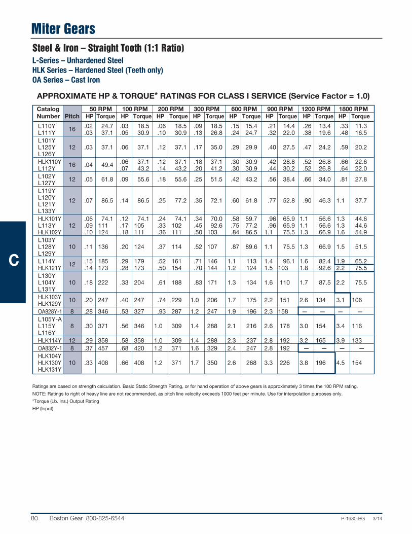
Miter Gears
80 Boston Gear 800-825-6544 P-1930-BG 3/14
Catalog 50 RPM 100 RPM 200 RPM 300 RPM 600 RPM 900 RPM 1200 RPM 1800 RPM Number Pitch HP Torque HP Torque HP Torque HP Torque HP Torque HP Torque HP Torque HP Torque
L110Y 16 .02 24.7 .03 18.5 .06 18.5 .09 18.5 .15 15.4 .21 14.4 .26 13.4 .33 11.3 L111Y .03 37.1 .05 30.9 .10 30.9 .13 26.8 .24 24.7 .32 22.0 .38 19.6 .48 16.5 L101Y L125Y 12 .03 37.1 .06 37.1 .12 37.1 .17 35.0 .29 29.9 .40 27.5 .47 24.2 .59 20.2 L126Y HLK110Y 16 .04 49.4 .06 37.1 .12 37.1 .18 37.1 .30 30.9 .42 28.8 .52 26.8 .66 22.6 L112Y .07 43.2 .14 43.2 .20 41.2 .30 30.9 .44 30.2 .52 26.8 .64 22.0 L102Y 12 .05 61.8 .09 55.6 .18 55.6 .25 51.5 .42 43.2 .56 38.4 .66 34.0 .81 27.8 L127Y L119Y L120Y 12 .07 86.5 .14 86.5 .25 77.2 .35 72.1 .60 61.8 .77 52.8 .90 46.3 1.1 37.7 L121Y L133Y HLK101Y .06 74.1 .12 74.1 .24 74.1 .34 70.0 .58 59.7 .96 65.9 1.1 56.6 1.3 44.6 L113Y 12 .09 111 .17 105 .33 102 .45 92.6 .75 77.2 .96 65.9 1.1 56.6 1.3 44.6 HLK102Y .10 124 .18 111 .36 111 .50 103 .84 86.5 1.1 75.5 1.3 66.9 1.6 54.9 L103Y L128Y 10 .11 136 .20 124 .37 114 .52 107 .87 89.6 1.1 75.5 1.3 66.9 1.5 51.5 L129Y L114Y 12 .15 185 .29 179 .52 161 .71 146 1.1 113 1.4 96.1 1.6 82.4 1.9 65.2 HLK121Y .14 173 .28 173 .50 154 .70 144 1.2 124 1.5 103 1.8 92.6 2.2 75.5 L130Y L104Y 10 .18 222 .33 204 .61 188 .83 171 1.3 134 1.6 110 1.7 87.5 2.2 75.5 L131Y HLK103Y 10 .20 247 .40 247 .74 229 1.0 206 1.7 175 2.2 151 2.6 134 3.1 106 HLK129Y OA828Y-1 8 .28 346 .53 327 .93 287 1.2 247 1.9 196 2.3 158 — — — — L105Y-A L115Y 8 .30 371 .56 346 1.0 309 1.4 288 2.1 216 2.6 178 3.0 154 3.4 116 L116Y HLK114Y 12 .29 358 .58 358 1.0 309 1.4 288 2.3 237 2.8 192 3.2 165 3.9 133 OA832Y-1 8 .37 457 .68 420 1.2 371 1.6 329 2.4 247 2.8 192 — — — — HLK104Y HLK130Y 10 .33 408 .66 408 1.2 371 1.7 350 2.6 268 3.3 226 3.8 196 4.5 154 HLK131Y
Steel & Iron – Straight Tooth (1:1 Ratio)L-Series – Unhardened SteelHLK Series – Hardened Steel (Teeth only)OA Series – Cast Iron
APPROXIMATE HP & TORQUE* RATINGS FOR CLASS I SERVICE (Service Factor = 1.0)
Ratings are based on strength calculation. Basic Static Strength Rating, or for hand operation of above gears is approximately 3 times the 100 RPM rating.
NOTE: Ratings to right of heavy line are not recommended, as pitch line velocity exceeds 1000 feet per minute. Use for interpolation purposes only.
*Torque (Lb. Ins.) Output Rating
HP (Input)
C

Miter Gears
P-1930-BG 3/14 Boston Gear 800-825-6544 81
Steel & Iron – Straight Tooth (1:1 Ratio)L-Series – Unhardened Steel
HLK Series – Hardened Steel (Teeth only)OA Series – Cast Iron
APPROXIMATE HP & TORQUE* RATINGS FOR CLASS I SERVICE (Service Factor = 1.0)
Ratings are based on strength calculation. Basic Static Strength Rating, or for hand operation of above gears is approximately 3 times the 100 RPM rating.
NOTE: Ratings to right of heavy line are not recommended, as pitch line velocity exceeds 1000 feet per minute. Use for interpolation purposes only.
*Torque (Lb. Ins.) Output Rating
HP (Input)
Catalog 50 RPM 100 RPM 200 RPM 300 RPM 600 RPM 900 RPM 1200 RPM 1800 RPM Number Pitch HP Torque HP Torque HP Torque HP Torque HP Torque HP Torque HP Torque HP Torque
L106Y L117Y 8 .42 519 .79 488 1.4 432 1.9 391 2.8 288 3.4 233 3.8 196 — — L132Y OA624Y 6 .46 568 .87 537 1.5 463 2.0 412 3.0 309 3.5 240 — — — — L123Y 8 .55 679 1.0 618 1.8 556 2.4 494 3.5 360 4.2 288 4.6 237 — — HLK105YA HLK115Y 8 .55 679 1.1 679 2.0 618 2.7 556 4.3 443 5.3 364 5.9 304 6.9 237 HLK116Y L107Y 6 .69 852 1.3 803 2.2 679 3.0 618 4.5 463 5.3 364 5.8 299 — — L118Y OA630Y-1 6 .82 1013 1.5 926 2.5 772 3.2 659 4.7 484 — — — — — — OA525Y 5 .90 1112 1.6 988 2.7 834 3.5 721 5.1 525 — — — — — — L134Y 6 .90 1112 1.6 988 2.8 865 3.7 762 5.4 556 6.4 439 7.0 360 — — L135Y HLK106Y HLK117Y 8 .80 988 1.6 988 2.8 865 3.7 762 5.7 587 6.8 467 7.6 391 — — HLK132Y OA636Y-1 6 1.1 1359 1.9 1174 3.2 988 4.1 844 5.8 597 — — — — — — HLK123Y 8 1.0 1235 2.0 1235 3.6 1112 4.7 968 7.0 721 8.4 576 9.2 474 — — L108Y L122Y 5 1.3 1606 2.4 1482 4.1 1266 5.3 1091 7.6 782 9.0 618 — — — — L136Y HLK107Y 6 1.3 1606 2.6 1606 4.5 1390 6.0 1235 8.0 824 11.0 755 12.0 618 — — HLK118Y OA424Y 4 1.6 1976 2.8 1729 4.6 1421 5.9 1215 8.2 844 — — — — — — OA540Y-1 5 2.0 2471 3.5 2162 5.6 1729 7.0 1441 — — — — — — — — L109Y 4 2.3 2841 4.2 2594 7.0 2162 8.7 1791 12.4 1276 14.3 981 — — — — L137Y L138Y 4 3.0 3706 5.3 3274 8.6 2656 10.8 2224 14.6 1503 16.6 1139 — — — — HLK108Y 5 2.4 2965 4.9 3026 8.2 2532 10.0 2059 15.0 1544 18.0 1235 — — — — HLK122Y HLK109Y 4 4.2 5188 8.3 5126 14.0 4324 17.0 3500 25.0 2574 28.0 1922 — — — —
C

Bevel Gears
82 Boston Gear 800-825-6544 P-1930-BG 3/14
Catalog 50 RPM† 100 RPM 200 RPM 300 RPM 600 RPM 900 RPM 1200 RPM 1800 RPMNumber Pitch Ratio HP Torque HP Torque HP Torque HP Torque HP Torque HP Torque HP Torque HP Torque
L146Y 16 .03 55.6 .06 55.6 .11 51.0 .16 49.4 .29 44.8 .40 41.2 .48 37.1 .62 31.9HL146Y 16 .04 74.1 .08 74.1 .16 74.1 .23 71.0 .41 63.3 .55 56.6 .67 51.7 .86 44.3L151Y 12 1-1/2:1 .10 185 .20 185 .37 171 .53 164 .91 141 1.19 122 1.41 109 1.74 89.6HL151Y 12 .14 259 .27 250 .52 241 .73 225 1.26 195 1.65 170 1.96 151 2.41 124L153Y 10 .24 445 .45 417 .84 389 1.17 361 1.93 298 2.47 254 2.88 222 3.44 177HL153Y 10 .33 611 .63 584 1.16 537 1.62 500 2.68 414 3.44 354 4.00 309 4.77 245L148Y 16 .02 49.4 .03 37.1 .06 37.1 .09 37.1 .17 35.0 .23 31.6 .28 28.8 .37 25.4HL148Y 16 .02 49.4 .04 49.4 .09 55.6 .12 49.4 .23 47.4 .32 43.9 .39 40.1 .52 35.7L149Y 16 2:1 .04 98.8 .09 111 .17 105 .24 98.8 .43 88.5 .58 79.6 .71 73.1 .91 62.5L150Y 14 .05 124 .09 111 .18 111 .26 107 .47 96.8 .64 87.8 .77 79.3 .99 67.9HL150Y 14 .07 173 .13 161 .25 154 .36 148 .65 134 .88 121 1.07 110 1.38 94.7HL149Y 16 .06 148 .12 148 .23 142 .33 136 .60 124 .81 111 .99 102 1.27 87.2PA3212Y 12 .04 99 .09 111 .16 99 .23 95 .40 82 .52 71 .62 64 .76 52.2PA4212Y 12 .08 198 .16 198 .29 179 .41 169 .68 140 .87 119 1.00 103 1.20 82.4L152Y 12 2:1 .14 346 .27 334 .50 309 .72 296 1.23 253 1.62 222 1.92 198 2.36 162PA5210Y 10 .15 371 .28 346 .51 315 .70 288 1.10 226 1.40 192 1.60 165 — —HL152Y 12 .19 469 .37 457 .70 432 .99 408 1.71 352 2.24 307 2.66 274 3.27 224L155Y 10 .30 741 .58 716 1.08 667 1.51 622 2.50 515 3.20 439 3.73 384 4.45 305PA528Y 8 .20 494 .38 469 .70 432 .96 395 1.50 309 1.90 261 2.20 226 — —L156Y 8 .54 1334 1.03 1272 1.88 1161 2.59 1066 4.16 856 5.21 715 5.96 614 6.97 478HL155Y 10 2:1 .42 1038 .81 1001 1.50 926 2.10 865 3.48 716 4.45 611 5.18 533 6.18 424PA626Y 6 .40 988 .75 926 1.30 803 1.80 741 2.90 597 3.50 480 4.00 412 — —PA625Y 5 .43 1062 .82 1013 1.50 926 2.00 824 3.10 638 3.80 522 4.30 443 — —PA726Y 6 .48 1186 .89 1099 1.60 988 2.10 865 3.90 803 — — — — — —L158Y 6 1.07 2644 2.02 2495 3.62 2236 4.92 2026 7.67 1579 9.43 1294 10.65 1096 12.24 840PA826Y 6 .63 1556 1.20 1482 2.00 1235 2.70 1112 4.00 824 4.80 659. — — — —HL156Y 8 2:1 .76 1878 1.44 1779 2.62 1618 3.60 1482 5.78 1190 7.24 994 8.28 852 9.68 664PA824Y 4 .98 2421 1.80 2224 3.20 1976 4.20 1729 7.30 1503 7.50 1029 — — — —HL158Y 6 1.49 3681 2.80 3459 5.02 3101 6.83 2812 10.65 2193 13.10 1798 14.79 1522 17.00 1167PA3316Y 16 .05 185 .11 204 .20 185 .30 185 .53 164 .72 148 .88 136 1.12 115PA45312Y 12 .16 593 .31 574 .59 547 .84 519 1.44 445 1.89 389 2.24 346 2.75 283PA6310Y 10 .34 1260 .66 1223 1.21 1121 1.70 1050 2.81 868 3.60 741 4.18 645 5.00 515PA638Y 8 3:1 .43 1594 .82 1519 1.52 1408 2.12 1309 3.51 1084 4.49 924 5.22 806 6.24 642L157Y 10 .34 1260 .66 1223 1.21 1121 1.70 1050 2.81 868 3.60 741 4.18 645 5.00 515PA7536Y 6 .88 3261 1.66 3076 3.03 2807 4.17 2576 6.69 2066 8.38 1725 9.59 1481 11.21 1154PA935Y 5 1.53 5670 2.88 5336 5.16 4781 7.01 4330 10.93 3375 13.44 2767 15.19 2346 17.45 1796PA4416Y 16 .06 296 .12 296 .24 296 .34 280 .61 251 .83 228 1.02 210 1.30 4178PA6412Y 12 .17 840 .32 791 .61 754 .86 708 1.48 609 1.94 533 2.31 476 2.83 388PA6410Y 10 4:1 .22 1087 .42 1038 .80 988 1.13 931 1.95 803 2.56 703 3.04 626 3.74 513PA848Y 8 .43 2125 .83 2051 1.54 1902 2.15 1771 3.56 1466 4.56 1252 5.30 1091 6.33 869PA948Y 8 .75 3706 1.43 3533 2.62 3236 3.64 2998 5.92 2438 7.50 2059 8.65 1781 10.21 1401PA6616Y 16 6:1 .09 667 .17 630 .33 611 .48 593 .86 531 1.17 482 1.42 439 1.82 375PA6612Y 12 .12 889 .23 852 .44 815 .63 778 1.13 698 1.54 634 1.88 581 2.40 494
APPROXIMATE HP & TORQUE* RATINGS FOR CLASS I SERVICE (Service Factor = 1.0)
Ratings are based on strength calculation. Basic Static Strength Rating, or for hand operation of above gears is approximately 3 times the 100 RPM rating.
*Torque (Lb. Ins.) Output Rating
HP (Input)
†RPM of Pinion
Steel & Iron – Straight Tooth L-Series/PA Series Pinions – Unhardened SteelPA Series – Cast IronHL Series – Hardened Steel (Teeth Only)
C

Steel Spiral Miter & Bevel Gears
P-1930-BG 3/14 Boston Gear 800-825-6544 83
Catalog 50 RPM 100 RPM 200 RPM 300 RPM 600 RPM 900 RPM 1200 RPM 1800 RPM Number Pitch HP Torque HP Torque HP Torque HP Torque HP Torque HP Torque HP Torque HP Torque
LSA110Y 18 .01 12.4 .02 12.4 .04 12.4 .07 14.4 .14 14.4 .20 13.7 .25 12.9 .35 12.0 LSA101Y 12 .02 24.7 .04 24.7 .08 24.7 .13 26.8 .25 25.7 .35 24.0 .45 23.2 .62 21.3 LSA102Y 12 .03 37.1 .07 43.2 .13 40.1 .20 41.2 .38 39.1 .54 37.1 .63 32.4 .95 32.6 HLSK110Y 18 .03 37.1 .07 43.2 .14 43.2 .21 43.2 .42 43.2 .59 40.5 .76 39.1 1.0 34.3 HLSK101Y 12 .06 74.1 .13 80.3 .26 80.3 .39 80.3 .75 77.2 1.0 68.6 1.3 66.9 1.8 61.8 LSA103Y 10 .07 86.5 .15 92.6 .30 92.6 .44 90.6 .80 82.4 1.1 75.5 1.4 72.1 2.0 68.6 HLSK102Y 12 .10 124. .21 130. .41 127. .61 126 1.0 103 1.6 110 2.0 103 2.8 96.1 LSA104Y 10 .15 185 .30 185. .57 176. .83 171 1.5 154 2.0 137 2.6 134 3.6 124 LSA105YA 7 .22 272. .44 272. .84 259. 1.2 247 2.2 226 3.0 206 3.8 196 5.1 175 HLSK103Y 10 .23 284. .46 284. .89 275. 1.3 268 2.4 247 3.4 233 4.3 221 5.9 202 LSA106Y 8 .34 420 .69 426. 1.3 401. 1.8 371 3.3 340 4.5 309 5.7 293 7.8 268
LSA107Y 6 .46 568. .90 556. 1.7 525. 2.4 494 4.3 443 5.9 405 7.4 381 10.0 343 LSA118Y 6 .46 568 .90 556 1.7 525 2.4 494 4.3 443 5.9 405 7.4 381 10.0 343 HLSK104Y 10 .45 556. .90 556. 1.7 525. 2.5 515 4.5 463 6.1 419 7.9 407 11.1 381 HLSK105YA 7 .67 828. 1.3 803. 2.5 772. 3.6 741 6.5 669 9.0 618 11.0 566 15.0 515 LSA122Y 5 .83 1025. 1.6 988. 3.0 926. 4.3 885 7.5 772 10.0 686 12.0 618 17.0 583 HLSK106Y 8 1.0 1235. 2.0 1235. 3.9 1204. 5.6 1153 10.0 1029 13.0 892 17.0 875 23.0 789 HLSK107Y 6 1.3 1606. 2.7 1668. 5.1 1575. 7.3 1503 13.0 1338 17.0 1167 22.0 1132 33.0 1132 HLSK118Y 6 1.3 1606 2.7 1668 5.1 1575 7.3 1503 13.0 1338 17.0 1167 22.0 1132 33.0 1132 HLSK122Y 5 2.4 2965. 4.9 3026 9.1 2810. 13.1 2697 23.01 2378 30.0 2059 38.0 1956 51.0 1750
APPROXIMATE HP & TORQUE* RATINGS FOR CLASS I SERVICE (Service Factor = 1.0)
APPROXIMATE HP & TORQUE* RATINGS FOR CLASS I SERVICE (Service Factor = 1.0)
Catalog 50 RPM† 100 RPM† 200 RPM† 300 RPM† 600 RPM† 900 RPM† 1200 RPM† 1800 RPM†
Number Pitch HP Torque HP Torque HP Torque HP Torque HP Torque HP Torque HP Torque HP Torque
SS302 30 .002 4.9 .004 4.9 .008 4.9 .013 5.4 .025 5.1 .037 5.1 .05 5.1 .07 4.8 SH302 30 .005 12.4 .01 12.4 .02 12.4 .03 12.4 .06 12.4 .09 12.4 .12 12.4 .18 12.4 SS192 19 .01 24.7 .02 24.7 .04 24.7 .06 24.7 .12 24.7 .18 24.7 .24 24.7 .35 24.0 SS142 14 .02 49.4 .05 61.8 .09 55.6 .14 57.6 .26 53.5 .39 53.5 .51 52.5 .76 52.2 SH192 19 .03 74.1 .05 61.8 .10 61.8 .16 65.9 .31 63.8 .46 63.1 .60 61.8 .88 60.4 SS142-1 14 .04 98.8 .08 98.8 .16 98.8 .23 94.7 .45 92.6 .67 92.0 .88 90.6 1.3 89.2 SH142 14 .06 148 .12 148 .23 142 .34 140 .66 136 .98 135 1.3 134 1.9 130 SH142-1 14 .10 247 .20 247 .39 241 .58 239 1.1 226 1.7 233 2.2 226 3.2 220 SS102 10 .14 346 .27 334 .52 321 .78 321 1.5 309 2.2 302 2.9 299 4.3 295 SS82 8 .26 642 .50 618 .99 611 1.5 618 2.8 576 4.2 576 5.5 566 8.0 549 SH102 10 .34 840 .67 828 1.3 803 2.0 824 3.8 782 5.6 769 7.3 751 10.7 734 SH82 8 .64 1581 1.3 1606 2.5 1544 3.7 1524 7.1 1462 10.5 1441 13.7 1410 20.0 1373
Ratings are based on strength calculation. Basic Static Strength Rating, or for hand operation of above gears is approximately 3 times the 100 RPM rating.
*Torque (Lb. Ins.) Output Rating
HP (Input)
Note: Ratings to right of heavy line are not recommended, as pitch line velocity exceeds 1000 feet per minute. Use for interpolation purposes only.
**Ratings reflect Gear and Pinion sets.
†Pinion RPM
Steel Spiral Miter Gears (1:1 Ratio)LSA Series – Unhardened Steel
HLSK Series – Hardened Steel (Teeth Only)
Steel Spiral Bevel Gears** (2:1 Ratio)SS-Series – Unhardened Steel
SH Series – Hardened Steel (Teeth Only)
C

Notes
84 Boston Gear 800-825-6544 P-1930-BG 3/14
C

Worms & Worm Gears
P-1930-BG 3/14 Boston Gear 800-825-6544 85
CATALOG NUMBERS / DIMENSIONS .............................................................................................. 86-95
SELECTION PROCEDURE....................................................................................................................... 96
HORSEPOWER & TORQUE RATINGS............................................................................................... 97-98
CENTER DISTANCES & RATIOS AVAILABLE........................................................................................ 98
STOCK ALTERED / CUSTOM WORM AND WORM GEARS ............................................................... 3-5
WORM/WORM GEAR ENGINEERING INFORMATION................................................................ 310-311
Section Contents
D

Worms & Worm Gears
86 Boston Gear 800-825-6544 P-1930-BG 3/14
48 Diametral Pitch (Bronze Worm Gears, Steel Worms – Unhardened & Hardened, Acetal Worm Gears & Worms)Pressure Angle – Single thread 14-1/2° – Double thread 20° – Quad thread 25°
STANDARD TOLERANCES
DIMENSION TOLERANCE
Bronze All ±.0005 and Steel BORE Acetal All +.001 –.002 Acetal with All +.001 –.000 Brass Insert
WORM LEAD and LEAD ANGLE
SINGLE DOUBLE QUAD
LEAD .0654" .1309" .2618"LEAD 3°35´ 7°7´ 14°2´ANGLE
REFERENCE PAGES
Alterations — 314Lubrication — 314Materials — 315
RATIO = Gear Teeth ÷ Worm ThreadsAll Worms and Worm Gears stocked RIGHT HAND ONLY.
48 WORMS FOR ABOVE GEARSDIAMETRAL PITCH Hub SINGLE Thread DOUBLE Thread QUAD Thread Pitch Catalog Item Catalog Item Catalog Item Dia. Face Bore Dia. Proj. Number Code Number Code Number Code
ACETAL
.333 .562 .187 .26 .19 LSHP 54141 – – – –UNHARDENED – STEEL
.333 .562 .1875 .26 .19 LSH-1 12920 DSH-1 12928 QSH-1 12934HARDENED – STEEL
.333 .562 .1875 .26 .19 HLSH-1 13026 HDSH-1 13052 HQSH-1 13062 GLSH-1 12952 GDSH-1 13036 GQSH-1 13042
All Steel worms have .0625 drilled hole in hub.Hxxx worms have polished threads.Gxxx worms have ground and polished threads.
FACE
PITCHDIA.
HUBDIA.BORE
HUBPROJ.
*
FACE
PITCHDIA.
HUBDIA.BORE
HUBPROJ.
ALL DIMENSIONS IN INCHESORDER BY CATALOG NUMBER OR ITEM CODE
FACE = .156"48 WORM *CENTER LINE WORM TODIAMETRAL PITCH GEARS FLUSH END = .078" Style No. Hub See SINGLE Thread DOUBLE Thread QUAD Thread of Pitch Page Catalog Item Catalog Item Catalog Item Teeth Dia. Bore Dia. Proj. 315 Number Code Number Code Number Code
ACETAL**
20 .417 .34 .19 GP1018 54106 – – – – 30 .625 .187 .44 B GP1019 54107 – – – – 40 .833 .50 .25 GP1020 54108 – – – – 50 1.042 GP1021 54109 – – – –
ACETAL WITH BRASS INSERTS**
20 .417 .125 .34 .19 GP1018-1/8 54118 – – – –
30 .625 .125 .44 .25 GP1019-1/8 54119 – – – – .188 GP1019-3/16 54120 – – – –
40 .833 .188 .50 .25 B GP1020-3/16 54121 – – – – .250 GP1020-1/4 54122 – – – –
50 1.042 .188 .50 .25 GP1021-3/16 54123 – – – – .250 GP1021-1/4 54124 – – – –
BRONZE
20 .417 .34 .19 G1018 13564 D1118 13488 Q1318 13440 30 .625 .44 G1019 13566 D1119 13490 Q1319 13442 40 .833 .1875 .50 .25 A G1020 13568 D1120 13492 Q1320 13444 50 1.042 .50 G1021 13570 D1121 13494 Q1321 13446 60 1.250 .62 G1024 13572 D1124 13500 Q1324 13452 80 1.667 .250 .62 .31 G1022 13574 D1122 13496 Q1322 13448 100 2.083 .69 B G1023 13576 D1123 13498 Q1323 13450
D

Worms & Worm Gears
P-1930-BG 3/14 Boston Gear 800-825-6544 87
WORM LEAD and LEAD ANGLE
SINGLE DOUBLE QUAD
LEAD .0982" .1963" .3927"LEAD 4°5´ 8°8´ 15°57´ANGLE
STANDARD TOLERANCES
DIMENSION TOLERANCE
Bronze All ±.0005 and Steel BORE Acetal All +.001 –.002 Acetal with All +.001 –.000 Brass Insert
ALL DIMENSIONS IN INCHESORDER BY CATALOG NUMBER OR ITEM CODE
FACE = .219"32 WORM *CENTER LINE WORM TODIAMETRAL PITCH GEARS FLUSH END = .109" Style No. Hub See SINGLE Thread DOUBLE Thread QUAD Thread of Pitch Page Catalog Item Catalog Item Catalog Item Teeth Dia. Bore Dia. Proj. 315 Number Code Number Code Number Code
ACETAL**
20 .625 .187 .50 .25 GP1026 54110 – – – – 30 .938 .63 B GP1027 54111 – – – – 40 1.250 .250 .63 .31 GP1028 54112 – – – – 50 1.562 .63 GP1029 54113 – – – –
ACETAL WITH BRASS INSERTS**
20 .625 .188 .50 .25 GP1026-3/16 54125 – – – – .250 GP1026-1/4 54126 – – – –
30 .938 .188 .63 .25 GP1027-3/16 54127 – – – – .250 B GP1027-1/4 54128 – – – –
40 1.250 .250 .63 .31 GP1028-1/4 54129 – – – – .313 GP1028-5/16 54130 – – – –
50 1.562 .250 .63 .31 GP1029-1/4 54131 – – – – .3125 GP1029-5/16 54132 – – – –
BRONZE
20 .625 .1875 .50 .25 G1026 13578 D1126 13502 Q1326 13454 30 .938 .62 G1027 13580 D1127 13504 Q1327 13456 40 1.250 .62 A G1028 13582 D1128 13506 Q1328 13458 50 1.562 .250 .62 .31 G1029 13584 D1129 13508 Q1329 13460 60 1.875 .69 G1032 13586 D1132 13514 Q1332 13466 80 2.500 G1030 13588 D1130 13510 Q1330 13462 96 3.000 .3125 .69 .31 D G1031 13590 – – Q1331 13464 100 3.125 G1033 13592 D1133 13516 – –
RATIO = Gear Teeth ÷ Worm ThreadsAll Worms and Worm Gears stocked RIGHT HAND ONLY.
32 WORMS FOR ABOVE GEARSDIAMETRAL PITCH Hub SINGLE Thread DOUBLE Thread QUAD Thread Pitch Catalog Item Catalog Item Catalog Item Dia. Face Bore Dia. Proj. Number Code Number Code Number Code
ACETAL
.438 .641 .187 .32 .19 LTHBP 54142 – – – –UNHARDENED – STEEL
.438 .688 .1875 .32 .19 LTHB-1 12922 DTH-1 12930 QTH-1 12936HARDENED – STEEL
.438 .688 .2187 .32 .19 HLTH-1 13028 HDTH-1 13054 HQTH-1 13064 GLTH-1 12954 GDTH-1 13038 GQTH-1 13044
All Steel worms have .0625 drilled hole in hub.Hxxx worms have polished threads.Gxxx worms have ground and polished threads.**These are in effect Helical Gears with a Helix Angle compatible with the worms. When in mesh theyoperate as a worm pair at right angles. Face Width is 3/16".
32 Diametral Pitch (Bronze Worm Gears, Steel Worms – Unhardened & Hardened, Acetal Worm Gears & Worms)
Pressure Angle – Single thread 14-1/2° – Double thread 20° – Quad thread 25°
REFERENCE PAGES
Alterations — 314Lubrication — 314Materials — 315
FACE
PITCHDIA.
HUBDIA.BORE
HUBPROJ.
*
FACE
PITCHDIA.
HUBDIA.BORE
HUBPROJ.
D
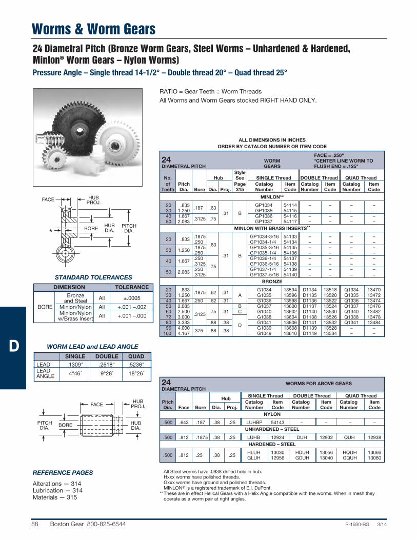
Worms & Worm Gears
88 Boston Gear 800-825-6544 P-1930-BG 3/14
REFERENCE PAGES
Alterations — 314Lubrication — 314Materials — 315
ALL DIMENSIONS IN INCHESORDER BY CATALOG NUMBER OR ITEM CODE
FACE = .250"24 WORM *CENTER LINE WORM TODIAMETRAL PITCH GEARS FLUSH END = .125" Style No. Hub See SINGLE Thread DOUBLE Thread QUAD Thread of Pitch Page Catalog Item Catalog Item Catalog Item Teeth Dia. Bore Dia. Proj. 315 Number Code Number Code Number Code
MINLON**
20 .833 .187 .63 GP1034 54114 – – – – 30 1.250 .31 B GP1035 54115 – – – – 40 1.667 .3125 .75 GP1036 54116 – – – – 50 2.083 GP1037 54117 – – – –
MINLON WITH BRASS INSERTS**
20 .833 .1875 GP1034-3/16 54133 – – – – .250 .63 GP1034-1/4 54134 – – – –
30 1.250 .1875 GP1035-3/16 54135 – – – – .250 .31 B GP1035-1/4 54136 – – – –
40 1.667 .250 GP1036-1/4 54137 – – – – .3125 .75 GP1036-5/16 54138 – – – –
50 2.083 .250 GP1037-1/4 54139 – – – – .3125 GP1037-5/16 54140 – – – –
BRONZE
20 .833 .1875 .62 .31 G1034 13594 D1134 13518 Q1334 13470 30 1.250 A G1035 13596 D1135 13520 Q1335 13472 40 1.667 .250 .62 .31 G1036 13598 D1136 13522 Q1336 13474 50 2.083 B G1037 13600 D1137 13524 Q1337 13476 60 2.500 .3125 .75 .31 C G1040 13602 D1140 13530 Q1340 13482 72 3.000 G1038 13604 D1138 13526 Q1338 13478 80 3.333 .88 .38 D G1041 13606 D1141 13532 Q1341 13484 96 4.000 .375 .88 .38 G1039 13608 D1139 13528 – – 100 4.167 G1049 13610 D1149 13534 – –
RATIO = Gear Teeth ÷ Worm ThreadsAll Worms and Worm Gears stocked RIGHT HAND ONLY.
24 WORMS FOR ABOVE GEARSDIAMETRAL PITCH Hub SINGLE Thread DOUBLE Thread QUAD Thread Pitch Catalog Item Catalog Item Catalog Item Dia. Face Bore Dia. Proj. Number Code Number Code Number Code
NYLON
.500 .643 .187 .38 .25 LUHBP 54143 – – – –UNHARDENED – STEEL
.500 .812 .1875 .38 .25 LUHB 12924 DUH 12932 QUH 12938HARDENED – STEEL
.500 .812 .25 .38 .25 HLUH 13030 HDUH 13056 HQUH 13066 GLUH 12956 GDUH 13040 GQUH 13060
All Steel worms have .0938 drilled hole in hub.Hxxx worms have polished threads.Gxxx worms have ground and polished threads.MINLON® is a registered trademark of E.I. DuPont.
** These are in effect Helical Gears with a Helix Angle compatible with the worms. When in mesh theyoperate as a worm pair at right angles.
STANDARD TOLERANCES
DIMENSION TOLERANCE
Bronze All ±.0005 and Steel BORE Minlon/Nylon All +.001 –.002 Minlon/Nylon All +.001 –.000 w/Brass Insert
WORM LEAD and LEAD ANGLE
SINGLE DOUBLE QUAD
LEAD .1309" .2618" .5236"LEAD 4°46´ 9°28´ 18°26´ANGLE
FACE
PITCHDIA.
HUBDIA.BORE
HUBPROJ.
*
FACE
PITCHDIA.
HUBDIA.BORE
HUBPROJ.
24 Diametral Pitch (Bronze Worm Gears, Steel Worms – Unhardened & Hardened, Minlon® Worm Gears – Nylon Worms)Pressure Angle – Single thread 14-1/2° – Double thread 20° – Quad thread 25°
D

Worms & Worm Gears
P-1930-BG 3/14 Boston Gear 800-825-6544 89
All worms have .0938 drilled hole in hub.Hxxx worms have polished threads.Gxxx worms have ground and polished threads.
REFERENCE PAGES
Alterations — 314Lubrication — 314Materials — 315
ALL DIMENSIONS IN INCHESORDER BY CATALOG NUMBER OR ITEM CODE
FACE = .313"16 WORM *CENTER LINE WORM TODIAMETRAL PITCH GEARS FLUSH END = .156" Style No. Hub See SINGLE Thread DOUBLE Thread QUAD Thread of Pitch Page Catalog Item Catalog Item Catalog Item Teeth Dia. Bore Dia. Proj. 315 Number Code Number Code Number Code
BRONZE
20 1.250 .250 .62 .31 A G1042 13612 D1142 13700 Q1342 13536 30 1.875 .3125 .75 .38 B G1043 13614 D1143 13702 Q1343 13538 40 2.500 C G1044 13616 D1144 13704 Q1344 13540 50 3.125 G1045 13618 D1145 13706 Q1345 13542 60 3.750 .375 .88 .44 D G1048 13620 D1148 13708 Q1348 13544 80 5.000 G1046 13622 – – Q1346 13546 100 6.250 1.00 .50 G1047 13624 – – – –
CAST IRON
20 1.250 .250 .62 .31 A CG1042 63506 CD1142 63513 CQ1342 63518 30 1.875 .3125 .75 .38 B CG1043 63507 CD1143 63514 CQ1343 63519 40 2.500 CG1044 63508 CD1144 63515 CQ1344 63520 50 3.125 CG1045 63509 CD1145 63516 CQ1345 63521 60 3.750 .375 .88 .44 C CG1048 63510 CD1148 63517 CQ1348 63522 80 5.000 CG1046 63511 – – CQ1346 63523 100 6.250 1.00 .50 CG1047 63512 – – – –
RATIO = Gear Teeth ÷ Worm ThreadsAll Worms and Worm Gears stocked RIGHT HAND ONLY.
16 WORMS FOR ABOVE GEARSDIAMETRAL PITCH Hub SINGLE Thread DOUBLE Thread QUAD Thread Pitch Catalog Item Catalog Item Catalog Item Dia. Face Bore Dia. Proj. Number Code Number Code Number Code
UNHARDENED – STEEL
.625 1.00 .250 .44 .25 LVHB-1 12926 DVH-1 12862 QVH-1 12940HARDENED – STEEL
.625 1.00 .3125 .44 .25 HLVH-1 13032 HDVH-1 13004 HQVH-1 13058 GLVH-1 12958 GDVH-1 12950 GQVH-1 13046
WORM LEAD and LEAD ANGLE
SINGLE DOUBLE QUAD
LEAD .1963" .3927" .7854"LEAD 5°43´ 11°19´ 21°48´ANGLE
STANDARD TOLERANCES
DIMENSION TOLERANCE
BORE All ±.0005
FACE
PITCHDIA.
HUBDIA.BORE
HUBPROJ.
*
FACE
PITCHDIA.
HUBDIA.BORE
HUBPROJ.
16 Diametral Pitch (Bronze & Cast Iron Worm Gears, Steel Worms – Unhardened & Hardened)
Pressure Angle – Single thread 14-1/2° – Double thread 14-1/2° – Quad thread 25°
D

Worms & Worm Gears
90 Boston Gear 800-825-6544 P-1930-BG 3/14
STANDARD TOLERANCES
DIMENSION TOLERANCE
BORE All ±.0005
REFERENCE PAGES
Alterations — 314Horsepower Ratings — 97, 98Lubrication — 314Materials — 315Selection Procedure — 96
WORM LEAD and LEAD ANGLE
SINGLE DOUBLE QUAD
LEAD .2618" .5236" 1.0472"LEAD 4°46´ 9°28´ 18°26´ANGLE
RATIO = Gear Teeth ÷ Worm ThreadsRH = RIGHT HAND — LH = LEFT HANDAll others stocked RIGHT HAND ONLY.
ALL DIMENSIONS IN INCHESORDER BY CATALOG NUMBER OR ITEM CODE
FACE = .500"12 WORM *CENTER LINE WORM TODIAMETRAL PITCH GEARS FLUSH END = .250" Style No. Hub See SINGLE Thread DOUBLE Thread QUAD Thread of Pitch Page Catalog Item Catalog Item Catalog Item Teeth Dia. Bore Dia. Proj. 315 Number Code Number Code Number Code
BRONZE
12 1.000 .5625 1.00 .62 – – – – QB1212† 13762 16 1.333 .6875 1.25 .62 A – – – – QB1216† 13764 20 1.667 .500 1.25 .50 GB1050A 13626 DB1400 13714 DB1600 13766
30 2.500 .500 1.19 .62 GB1051 13628 – – – – .750 .62 – – DB1401A 13716 DB1601A 13768
40 3.333 .625 1.44 .62 GB1052A 13630 – – – – .750 .62 B – – DB1402A 13718 DB1602A 13770
50 4.167 .625 1.44 .62 GB1053A 13632 – – – – .750 .62 – – DB1403A 13720 DB1603A 13772
60 5.000 .625 1.69 .62 GB1260A 13634 – – – – .750 .62 – – DB1260A 13722 QB1260A 13774 80 6.667 .625 1.94 .75 C GB1054 13636 – – – – 100 8.333 .750 1.94 .75 GB1055 13638 – – – –
CAST IRON
20 1.667 .500 1.25 .50 A G1050ARH 13110 D1400RH 13260 D1600 13352 G1050ALH 13112 D1400LH 13262 .500 .62 G1051RH 13114 – – – – 30 2.500 1.19 G1051LH 13116 .750 .62 – – D1401ARH 13264 D1601A 13354 D1401ALH 13266 .625 .62 G1052ARH 13118 – – – – 40 3.333 1.44 G1052ALH 13120 .750 .62 – – D1402ARH 13268 D1602A 13356 B D1402ALH 13270 .625 .62 G1053ARH 13122 – – – – 50 4.167 1.44 G1053ALH 13124 .750 .62 – – D1403ARH 13272 D1603A 13358 D1403ALH 13274 .625 G1260RH 13126 – – – – 60 5.000 1.69 .75 G1260LH 13128 .750 – – D1260A 13276 Q1260A 13360
80 6.667 .625 1.94 .75 G1054 13130 – – – – .750 – – D1404 13278 – – 100 8.333 .750 1.94 .75 C G1055 13134 – – – –
†.750" Face, Center Line Worm to Flush End = .375"‡Furnished with .125" Keyway.Hardened Worms have ground and polished threads.
FACE
PITCHDIA.
HUBDIA.BORE
HUBPROJ.
*
FACE
PITCHDIA.
HUBDIA.BORE
HUBPROJ.
12 WORMS FOR ABOVE GEARSDIAMETRAL PITCH Hub SINGLE Thread DOUBLE Thread QUAD Thread Pitch Catalog Item Catalog Item Catalog Item Dia. Face Bore Dia. Proj. Number Code Number Code Number Code
UNHARDENED – STEEL
1.125 .625 – – – – D1407KRH‡ 12806 D1607KRH‡ 12822 D1407KLH‡ 12808 D1607KLH‡ 12824
1.000 1.625 .625 – – – – L1407‡ 12912 – – .500 – – L1056‡ 12900 – – – –
1.125 .500 .75 .38 GH1056RH 12884 DH1407RH 12838 DH1607 12854 GH1056LH 12886 DH1407LH 12840 – –
HARDENED – STEEL
1.125 .625 – – – – H1407RH‡ 12980 H1607‡ 12996 H1407LH‡ 12982 – –
1.000 1.625 .625 – – – – HL1407‡ 13018 – – .500 – – HL1056‡ 13006 – – – –
1.125 .500 – – H1056RH‡ 12962 – – – – H1056LH‡ 12960 – – – –
12 Diametral Pitch (Bronze & Cast Iron Worm Gears, Steel Worms – Unhardened & Hardened) Pressure Angle – 14-1/2°
DD

Worms & Worm Gears
P-1930-BG 3/14 Boston Gear 800-825-6544 91
†.875" Face, Center Line Worm to Flush End = .438"‡Furnished with 3/16" Keyway.Hardened Worms have ground and polished threads.
REFERENCE PAGES
Alterations — 314Horsepower Ratings — 97, 98Lubrication — 314Materials — 315Selection Procedure — 96
STANDARD TOLERANCES
DIMENSION TOLERANCE
BORE All ±.0005
WORM LEAD and LEAD ANGLE
SINGLE DOUBLE QUAD
LEAD .3142" .6283" 1.2566"LEAD 4°34´ 9°5´ 17°45´ANGLE
RATIO = Gear Teeth ÷ Worm ThreadsRH = RIGHT HAND — LH = LEFT HANDAll others stocked RIGHT HAND ONLY.
ALL DIMENSIONS IN INCHESORDER BY CATALOG NUMBER OR ITEM CODE
FACE = .625"10 WORM *CENTER LINE WORM TODIAMETRAL PITCH GEARS FLUSH END = .312" Style No. Hub See SINGLE Thread DOUBLE Thread QUAD Thread of Pitch Page Catalog Item Catalog Item Catalog Item Teeth Dia. Bore Dia. Proj. 315 Number Code Number Code Number Code
BRONZE 16 1.600 .750 1.50 .75 – – – – QB1016† 13780
20 2.000 .500 1.25 .62 A GB1060A 13640 – – – – .875 1.62 – – DB1410 13728 DB1610 13782
30 3.000 .625 1.69 .62 GB1061A 13648 – – – – .875 – – DB1411 13736 DB1611 13788
40 4.000 .625 1.69 .62 GB1062A 13642 – – – – .875 B – – DB1412 13730 DB1612 13784
50 5.000 .750 1.94 .75 GB1063 13644 – – – – .875 – – DB1413A 13732 DB1613A 13786
60 6.000 .750 1.94 .75 GB1064 13646 – – – – .875 – – DB1414A 13734 – – 80 8.000 .750 1.94 .75 C GB1067 13650 – – – – 100 10.000 .750 2.00 .75 GB1065 13652 – – – –
CAST IRON .500 1.25 G1060ARH 13136 – – – – 20 2.000 .62 A G1060ALH 13138 .875 1.62 – – D1410RH 13282 D1610 13366 D1410LH 13284 .625 1.69 G1061ARH 13142 – – – – 30 3.000 .62 G1061ALH 13140 .875 1.69 – – D1411RH 13286 D1611 13368 D1411LH 13288 .625 1.69 G1062ARH 13144 – – – – 40 4.000 .62 G1062ALH 13146 .875 1.69 B – – D1412RH 13290 D1612 13370 D1412LH 13292 .750 1.94 G1063RH 13148 – – – – 50 5.000 .75 G1063LH 13150 .875 1.94 – – D1413ARH 13294 D1613A 13372 D1413ALH 13296 .750 1.94 G1064RH 13152 – – – – 60 6.000 .75 G1064LH 13154 .875 1.94 – – D1414A 13298 D1614A 13374
80 8.000 .750 1.94 .75 G1067RH 13156 – – – – .875 1.94 C – – D1080A 13300 Q1080A 13376
100 10.000 .750 1.94 .75 G1065 13158 – – – – .875 1.94 – – D1415A 13302 – –
FACE
PITCHDIA.
HUBDIA.BORE
HUBPROJ.
*
10 WORMS FOR ABOVE GEARSDIAMETRAL PITCH Hub SINGLE Thread DOUBLE Thread QUAD Thread Pitch Catalog Item Catalog Item Catalog Item Dia. Face Bore Dia. Proj. Number Code Number Code Number Code
UNHARDENED – STEEL
1.375 .750 – – – – D1418KRH‡ 12810 D1618KRH‡ 12826 – – D1418KLH‡ 12812 D1618KLH‡ 12828 2.000 .750 – – – – L1418‡ 12914 – –
1.250 .625 – – L1066‡ 12902 – – – – – – G1066KRH‡ 12864 – – – – 1.375 .625 G1066KLH‡ 12866 .97 .50 GH1066RH 12888 DH1418RH 12842 DH1618 12856 GH1066LH 12890 DH1418LH 12844 – –
HARDENED STEEL
1.375 .750 – – – – H1418RH‡ 12986 H1618‡ 12998 – – H1418LH‡ 12984 – –
1.250 2.000 .750 – – – – HL1418‡ 13020 – – .625 – – HL1066‡ 13008 – – – –
1.375 .625 – – H1066RH‡ 12966 – – – – H1066LH‡ 12964
FACE
PITCHDIA.
HUBDIA.BORE
HUBPROJ.
10 Diametral Pitch (Bronze & Cast Iron Worm Gears, Steel Worms – Unhardened & Hardened)
Pressure Angle – 14-1/2°
DD

Worms & Worm Gears
92 Boston Gear 800-825-6544 P-1930-BG 3/14
†1.000" Face, Center Line Worm to Flush End = .500"‡Furnished with .188" Keyway.Hardened Worms have ground and polished threads.
REFERENCE PAGES
Alterations — 314Horsepower Ratings — 97, 98Lubrication — 314Materials — 315Selection Procedure — 96
STANDARD TOLERANCES
DIMENSION TOLERANCE
BORE All ±.0005
WORM LEAD and LEAD ANGLE
SINGLE DOUBLE QUAD
LEAD .3927" .7854" 1.5708"LEAD 4°46´ 9°28´ 18°26´ANGLE
ALL DIMENSIONS IN INCHESORDER BY CATALOG NUMBER OR ITEM CODE
FACE = .750"8 WORM *CENTER LINE WORM TODIAMETRAL PITCH GEARS FLUSH END = .375" Style No. Hub See SINGLE Thread DOUBLE Thread QUAD Thread of Pitch Page Catalog Item Catalog Item Catalog Item Teeth Dia. Bore Dia. Proj. 315 Number Code Number Code Number Code
BRONZE 8 1.000 .500 1.12 .88 – – – – QB808† 13790 12 1.500 .750 1.50 .88 – – – – QB812† 13792 16 2.000 1.000 2.00 .88 A – – – – QB816† 13794
20 2.500 .750 1.75 .75 GB1070 13654 – – – – 1.000 1.75 .75 – – DB1420A 13740 DB1620A 13796
30 3.750 .750 1.69 .75 GB1071 13656 – – – – 1.000 1.69 .75 – – DB1421A 13742 DB1621A 13798 40 5.000 1.000 2.19 .75 B GB1072A 13658 DB1422 13744 DB1622 13800 48 6.000 1.000 2.38 .88 GB1073 13660 – – – – 50 6.250 1.000 2.31 .88 GB850RH 13662 DB1423A 13746 DB1623A 13802 60 7.500 1.000 2.44 .88 C GB860 13664 DB860A 13748 – – 80 10.000 1.250 2.75 .88 D GB1074A 13666 – – – – 100 12.500 1.250 3.00 1.00 C GB8100 13668 – – – –
CAST IRON
.750 1.75 .75 G1070RH 13160 – – – – 20 2.500 A G1070LH 13162
1.000 1.75 .75 – – D1420ARH 13304 D1620A 13380 D1420ALH 13306
.750 1.69 .75 G1071RH 13164 – – – – 30 3.750 G1071LH 13166
1.000 1.69 .75 – – D1421ARH 13308 D1621A 13382 D1421ALH 13310
40 5.000 1.000 1.69 .75 B G1072ARH 13168 D1422ARH 13312 D1622A 13384 G1072ALH 13170 D1422ALH 13314
48 6.000 1.000 2.38 .88 G1073RH 13174 – – – – G1073LH 13172
50 6.250 1.000 2.31 .88 G850RH 13176 D1423A 13316 D1623A 13386 G850LH 13178 60 7.500 1.000 2.44 .88 C G860 13180 D860A 13320 Q860A 13388
80 10.000 1.000 2.69 .88 D – – D1424A 13322 D1624A 13390 1.250 2.69 .88 D G1074ARH 13182 – – – – 96 12.000 1.250 3.00 1.00 C G1075 13186 – – – – 100 12.500 1.250 2.69 1.00 C G8100A 13188 – – – –
8 WORMS FOR ABOVE GEARSDIAMETRAL PITCH Hub SINGLE Thread DOUBLE Thread QUAD Thread Pitch Catalog Item Catalog Item Catalog Item Dia. Face Bore Dia. Proj. Number Code Number Code Number Code
UNHARDENED – STEEL
1.750 .875 – – – – D1427KRH‡ 12814 D1627KRH‡ 12830 D1427KLH‡ 12816 D1627KLH‡ 12832
2.500 .875 – – – – L1427‡ 12916 – –
1.500 .750 – – L1076‡ 12904 – – – –
.750 – – G1076KRH‡ 12868 – – – – 1.750 G1076KLH‡ 12870
.750 1.18 .62 GH1076RH 12892 DH1427RH 12846 DH1627 12858 GH1076LH 12894 DH1427LH 12848HARDENED STEEL
1.750 .875 – – – – H1427RH‡ 12990 H1627‡ 13000 H1427LH‡ 12988 – –
1.500 2.500 .875 – – – – HL1427‡ 13022 – – .750 – – HL1076‡ 13010 – – – –
1.750 .750 – – H1076RH‡ 12970 – – – – H1076LH‡ 12968
RATIO = Gear Teeth ÷ Worm ThreadsRH = RIGHT HAND — LH = LEFT HANDAll others stocked RIGHT HAND ONLY.
FACE
PITCHDIA.
HUBDIA.BORE
HUBPROJ.
*
FACE
PITCHDIA.
HUBDIA.BORE
HUBPROJ.
8 Diametral Pitch (Bronze & Cast Iron Worm Gears, Steel Worms – Unhardened & Hardened) Pressure Angle – 14-1/2°
D

Worms & Worm Gears
P-1930-BG 3/14 Boston Gear 800-825-6544 93
REFERENCE PAGES
Alterations — 314Horsepower Ratings — 97, 98Lubrication — 314Materials — 315Selection Procedure — 96
RATIO = Gear Teeth ÷ Worm ThreadsRH = RIGHT HAND — LH = LEFT HANDAll others stocked RIGHT HAND ONLY.
**1.250" Face, Center Line Worm to Flush End = .625"‡Furnished with .188" Keyway.†Furnished with .250" Keyway.Hardened Worms have ground and polished threads.
STANDARD TOLERANCES
DIMENSION TOLERANCE
BORE All ±.0005
WORM LEAD and LEAD ANGLE
SINGLE DOUBLE QUAD
LEAD .5236" 1.0472" 2.0944"LEAD 4°46´ 9°28´ 18°26´ANGLE
6 WORMS FOR ABOVE GEARSDIAMETRAL PITCH Hub SINGLE Thread DOUBLE Thread QUAD Thread Pitch Catalog Item Catalog Item Catalog Item Dia. Face Bore Dia. Proj. Number Code Number Code Number Code
UNHARDENED – STEEL
2.500 1.000 – – – – D1438KRH† 12818 D1638KRH† 12834 D1438KLH† 12820 D1638KLH† 12836
3.500 1.000 – – – – L1438 12918 – –
2.000 .875 – – L1086‡ 12906 – – – –
.875 – – G1086KRH‡ 12872 – – – – 2.500 G1086KLH‡ 12874
.875 1.56 .75 GH1086RH 12896 DH1438RH 12850 DH1638 12860 GH1086LH 12898 DH1438LH 12852HARDENED STEEL
2.500 1.000 – – – – H1438RH† 12994 H1638† 13002 H1438LH‡ 12992 – –
2.000 3.500 1.000 – – – – HL1438† 13024 – – .875 – – HL1086‡ 13012 – – – –
2.500 .875 – – H1086RH‡ 12974 – – – – H1086LH‡ 12972
ALL DIMENSIONS IN INCHESORDER BY CATALOG NUMBER OR ITEM CODE
FACE = 1.000"6 WORM *CENTER LINE WORM TODIAMETRAL PITCH GEARS FLUSH END = .500" Style No. Hub See SINGLE Thread DOUBLE Thread QUAD Thread of Pitch Page Catalog Item Catalog Item Catalog Item Teeth Dia. Bore Dia. Proj. 315 Number Code Number Code Number Code
BRONZE 16 2.667 1.250 2.38 1.00 – – – – QB616** 13804 .750 2.00 A GB1077A 13670 – – – – 20 3.333 1.000 2.00 .88 – – DB620A 13752 – – 1.250 2.00 – – – – QB620A 13806 24 4.000 .750 1.94 .88 GB1080A 13672 – – – – 1.250 – – DB1430A 13754 DB1630A 13808 30 5.000 .875 2.19 .88 GB1081 13674 – – – – 1.250 B – – DB1431A 13756 DB1631A 13810 36 6.000 1.000 2.50 .88 GB1082 13676 – – – – 40 6.667 1.000 2.44 .88 GB1078 13678 – – – – 1.250 – – DB1432A 13758 DB1632A 13812 48 8.000 1.250 2.75 1.00 GB1083 13680 – – – – 50 8.333 1.250 2.69 1.00 C GB1079 13612 – – – – 60 10.000 1.250 3.00 1.00 GB1087 13684 – – – – 72 12.000 1.250 3.00 1.25 GB1084 13686 – – – –
CAST IRON
.750 G1077RH 13190 – – – – 20 3.333 1.81 .88 G1077LH 13192
1.000 – – D620ARH 13326 Q620A 13394 D620ALH 13328
.750 G1080ARH 13194 – – – – 24 4.000 1.94 .88 G1080ALH 13196
1.250 – – D1430ARH 13330 D1630A 13396 D1430ALH 13332
.875 B G1081RH 13198 – – – – 30 5.000 2.19 .88 G1081LH 13200
1.250 – – D1431ARH 13334 D1631A 13398 D1431ALH 13336
36 6.000 1.000 2.50 .88 G1082RH 13202 – – – – G1082LH 13204
1.000 G1078RH 13206 – – – – 40 6.667 2.44 .88 G1078LH 13208
1.250 – – D1432ARH 13338 D1632A 13400 D1432ALH 13340
48 8.000 1.250 2.75 1.00 B G1083RH 13212 – – – – G1083LH 13210 50 8.333 1.250 2.69 1.00 G1079RH 13214 D1433 13342 D1633 13402 60 10.000 1.250 2.69 1.00 G1087ARH 13218 D660 13344 Q660 13404 72 12.000 1.250 2.94 1.00 C G1084ARH 13220 D1434 13346 D1634 13406 80 13.333 1.250 3.00 1.00 G1088ARH 13224 – – – – 96 16.000 1.375 3.00 1.00 G1085ARH 13226 – – – – 100 16.667 1.375 3.00 1.00 D G1089ARH 13228 – – – –
FACE
PITCHDIA.
HUBDIA.BORE
HUBPROJ.
*
FACE
PITCHDIA.
HUBDIA.BORE
HUBPROJ.
6 Diametral Pitch (Bronze & Cast Iron Worm Gears, Steel Worms – Unhardened & Hardened)
Pressure Angle – 14-1/2°
D

Worms & Worm Gears
94 Boston Gear 800-825-6544 P-1930-BG 3/14
REFERENCE PAGES
Alterations — 314Horsepower Ratings — 97, 98Lubrication — 314Materials — 315Selection Procedure — 96
STANDARD TOLERANCES
DIMENSION TOLERANCE
BORE All ±.0005
WORM LEAD and LEAD ANGLE
LEAD .7854LEAD ANGLE 4°46´
4 WORMS FOR ABOVE GEARSDIAMETRAL PITCH Hub SINGLE Thread Pitch Catalog Item Dia. Face Bore Dia. Proj. Number* Code
UNHARDENED – STEEL
3.500 1.250 – – G1106KRH 12876 3.000 G1106KLH 12878 4.500 1.250 – – L1106 12908
HARDENED STEEL
3.500 1.250 – – H1106 12976 3.000 4.500 1.250 – – HL1106 13014 5.750 HP1106 13034
RATIO = Gear Teeth ÷ Worm ThreadsRH = RIGHT HAND — LH = LEFT HANDAll others stocked RIGHT HAND ONLY.
ALL DIMENSIONS IN INCHESORDER BY CATALOG NUMBER OR ITEM CODE
FACE = 1.500" *CENTER LINE WORM TO FLUSH END = .750"4 WORMDIAMETRAL PITCH GEARS Style No. Hub See SINGLE Thread of Pitch Page Catalog Item Teeth Dia. Bore Dia. Proj. 315 Number Code
BRONZE 20 5.000 1.000 2.50 1.25 B GB1100 13688 24 6.000 GB1101 13690
CAST IRON
20 5.000 G1100RH 13230
1.000 2.50 G1100LH 13232
24 6.000 G1101RH 13234
1.25 B G1101LH 13236
32 8.000 G1102RH 13238 1.250 3.00 G1102LH 13240 40 10.000 G1103RH 13242 48 12.000 1.500 3.50 G1104RH 13244 64 16.000 D G1105RH 13246
*All worms furnished with .313 keyway.Hardened Worms have ground and polished threads.
FACE
PITCHDIA.
HUBDIA.BORE
HUBPROJ.
*
FACE
PITCHDIA. BORE
KEYWAY
4 Diametral Pitch (Bronze & Cast Iron Worm Gears, Steel Worms – Unhardened & Hardened) Pressure Angle – 14-1/2°
D

Worms & Worm Gears
P-1930-BG 3/14 Boston Gear 800-825-6544 95
REFERENCE PAGES
Alterations — 314Horsepower Ratings — 97, 98Lubrication — 314Materials — 315Selection Procedure — 96
STANDARD TOLERANCES
DIMENSION TOLERANCE
BORE All ±.0005
WORM LEAD and LEAD ANGLE
LEAD 1.0472"LEAD ANGLE 4°46'
RATIO = Gear Teeth ÷ Worm ThreadsAll Worm and Worm Gears stocked RIGHT HAND ONLY.
ALL DIMENSIONS IN INCHESORDER BY CATALOG NUMBER OR ITEM CODE
FACE = 2.000" *CENTER LINE WORM TO FLUSH END = 1.000"3 WORMDIAMETRAL PITCH GEARS Style No. Hub See SINGLE Thread of Pitch Page Catalog Item Teeth Dia. Bore Dia. Proj. 315 Number Code 18 6.000 1.000 3.00 1.50 G1110 13248 24 8.000 B G1111 13250 30 10.000 3.50 G1112 13252 36 12.000 1.500 1.50 G1113 13254 48 16.000 4.00 C G1114 13256 54 18.000 D G1115 13258
†All worms furnished with .375" keyway.Hardened Worms have ground and polished threads.
3 WORMS FOR ABOVE GEARS†DIAMETRAL PITCH Hub SINGLE Thread Pitch Catalog Item Dia. Face Bore Dia. Proj. Number Code
UNHARDENED – STEEL
4.000 4.000 1.500 – – G1116KRH 12880 5.500 L1116 12910
HARDENED STEEL
4.000 4.000 1.500 – – H1116 12978 5.500 HL1116 13016
FACE
PITCHDIA.
HUBDIA.BORE
HUBPROJ.
*
FACE
PITCHDIA. BORE
KEYWAY
3 Diametral Pitch (Cast Iron Worm Gears, Steel Worms – Unhardened & Hardened) Pressure Angle – 14-1/2°
D

Worms & Worm Gears
96 Boston Gear 800-825-6544 P-1930-BG 3/14
Selection ProcedureApproximate input horsepower and output torque ratings forBoston stock worm and worm gear combinations from 12 to 3 DP are listed on Pages 97, 98. These ratings are for hardened, ground and polished worms operating with bronzeworm gears. For other combinations multiply the listed ratingsby the following percentages:
Hardened, ground and polished steel worms with cast irongears 50%. Unhardened steel worms with cast iron gears25%.
These ratings are listed at selected worm speeds. Ratings forinter mediate speeds can be interpolated from the values indicated.
These ratings are based on gears operating with a ServiceFactor of 1.0, properly mounted in accordance with gooddesign practice and continuously lubricated with a sufficientsupply of oil.
1. Determine service factor.a. Using Application Classification Chart I, pages 323, 324,
determine service factor orb. With knowledge of operating conditions and load
classification, select service factor from Table 1.
2. Determine Design Horsepower.
Design HP = Application Load x Service Factor (Table 1)
3. Select worm gear set with horsepower capacity equal to [orgreater than] design horsepower determined in Step 2.
Boston worms and worm gears provide an effective answer for such power transmission applications as high-ratio speed reduction, limited space, right-angleshafts and non-intersecting shafts. When properly applied, they are the smoothestand quietest form of gearing. Steel worms and cast iron or bronze worm gears areavailable in single, double or quadruple threads, 48 to 3 diametral pitch.
Acetal worms and worm gears are available in single thread, 48 to 24 diametral pitch.
Service Factor Operating Conditions
0.8 Uniform—not more than 15 minutes in 2 hours.
1.0 Moderate Shock—not more than 15 minutes in 2 hours.Uniform—not more than 10 hours per day.
1.25 Moderate Shock—not more than 10 hours per day.Uniform—more than 10 hours per day.
1.50 Heavy Shock—not more than 15 minutes in 2 hours.Moderate Shock—more than 10 hours per day.
1.75 Heavy Shock—not more than 10 hours per day.
2.0 Heavy Shock—more than 10 hours per day.
TABLE 1
Heavy shock loads and/or severe wear conditions may require the use of higherservice factors. Consultation with factory is recommended in these applications.
D

Worms & Worm Gears
P-1930-BG 3/14 Boston Gear 800-825-6544 97
Worm RPM 1800 600 100 Worm Gear Center Input Output Input Output Input Output Cat. Cat. Ratio Distance HP Torque HP Torque HP Torque No. No. DP
3 1.000 .52 50 .27 72 .06 83 H1607 QB1212 12 1.500 1.19 109 .66 183 .15 227 H1627 QB812 8 1.167 .78 99 .40 143 .08 166 H1607 QB1216 12 4 1.425 1.11 142 .61 223 .13 267 H1618 QB1016 10 1.750 1.77 216 .98 361 .22 454 H1627 QB816 8 2.333 3.01 392 1.84 689 .45 933 H1638 QB616 6 1.333 .68 109 .34 158 .07 180 H1607 DB1600 12 5 1.625 1.03 165 .57 257 .12 309 H1618 DB1610 10 2.000 1.73 264 .96 441 .22 551 H1627 DB1620A 8 2.667 3.92 639 2.40 1124 .59 1512 H1638 QB620A 6 6 3.000 3.82 746 2.34 1317 .57 1777 H1638 DB1630A 6 1.750 1.04 247 .53 355 .11 411 H1607 DB1601A 12 7.5 2.125 1.59 381 .87 599 .19 714 H1618 DB1611 10 2.625 2.65 607 1.47 1016 .33 1276 H1627 DB1621A 8 3.500 4.80 1174 2.94 2064 .72 2789 H1638 DB1631A 6 1.333 .44 130 .23 189 .05 208 H1407 DB1400 12 1.625 .67 196 .38 305 .09 366 H1418 DB1410 10 2.000 1.05 318 .63 525 .15 649 H1427 DB1420A 8 10 2.167 1.39 441 .71 641 .15 756 H1607 DB1602A 12 2.667 2.01 616 1.26 1071 .32 1450 H1438 DB620A 6 2.625 2.11 672 1.16 1061 .25 1267 H1618 DB1612 10 3.250 3.54 1082 1.96 1806 .44 2270 H1627 DB1622 8 4.333 6.43 2094 3.94 3685 .96 4980 H1638 DB1632A 6 12 3.000 2.39 882 1.50 1537 .38 2042 H1438 DB1430A 6 2.583 1.72 683 .87 985 .18 1134 H1607 DB1603A 12 12.5 3.125 2.61 1042 1.44 1641 .31 1961 H1618 DB1613A 10 3.875 4.40 1681 2.44 2810 .55 3466 H1627 DB1623A 8 1.750 .64 284 .33 410 .07 463 H1407 DB1401A 12 2.125 .98 436 .55 678 .13 804 H1418 DB1411 10 15 2.625 1.54 699 .92 1150 .22 1428 H1427 DB1421A 8 3.000 2.04 966 1.03 1402 .22 1617 H1607 QB1260A 12 3.500 2.94 1355 1.84 2364 .47 3120 H1438 DB1431A 6 18 5.000† 2.27 1308 1.38 2373 .41 4198 H1116 G1110† 3 1.333 .28 140 .15 210 .04 227 H1056 GB1050A 12 1.625 .42 217 .25 336 .06 391 H1066 GB1060A 10 2.000 .65 343 .41 567 .10 706 H1076 GB1070 8 2.167 .83 483 .43 693 .09 794 H1407 DB1402A 12 20 2.667 1.22 665 .80 1156 .22 1550 H1086 GB1077A 6 2.625 1.25 742 .71 1156 .16 1374 H1418 DB1412 10 3.250 1.98 1191 1.18 1974 .28 2433 H1427 DB1422 8 4.000 2.92 1667 1.99 3025 .64 4663 H1106 GB1100 4 4.333 3.77 2318 2.36 4034 .60 5420 H1438 DB1432A 6 3.000 1.42 933 .93 1613 .26 2163 H1086 GB1080A 6 24 6.000† 3.23 2218 1.81 4020 .53 7109 H1116 G1111† 3 4.500 3.41 2336 2.32 4235 .75 6504 H1106 GB1101 4 2.583 .99 726 .52 1048 .11 1197 H1407 DB1403A 12 25 3.125 1.50 1112 .85 1730 .19 2048 H1418 DB1413A 10 3.875 2.39 1794 1.43 2962 .34 3671 H1427 DB1423A 8 5.167 2.27 1738 1.42 3028 .36 4018 H1438 D1433† 6 1.750 .40 294 .21 410 .05 473 H1056 GB1051 12 2.125 .59 452 .35 693 .09 831 H1066 GB1061A 10 2.625 .90 725 .57 1197 .13 1286 H1076 GB1071 8 30 3.000 1.15 1008 .60 1450 .13 1663 H1407 DB1260A 12 3.500 1.69 1386 1.12 2426 .31 3233 H1086 GB1081A 6 3.625 1.74 1544 .98 2395 .22 2836 H1418 DB1414A 10 4.500 2.75 2489 1.65 4128 .39 5105 H1427 DB860A 8 7.000† 4.23 3326 2.53 6002 .76 10683 H1116 G1112† 3 32 5.500 2.13 1955 1.46 3546 .47 5445 H1106 G1102† 4 36 4.000 1.95 1915 1.29 3366 .36 4470 H1086 GB1082A 6 8.000† 3.87 3990 1.33 4130 .68 12816 H1116 G1113† 3
Steel-Hardened, Ground & Polished WormsBronze Worm Gears
Approximate Horsepower and Torque* RatingsFor Class I Service (Service Factor = 1.0)
*Torque in Lb. Ins.
†Cast Iron Gear Rating with Hardened Worm shown.
All Worm and Worm Gear Ratings are based on a Hardened Steel Worm used with a Bronze Worm Gear.1. For a Hardened Steel Worm used with a Cast Iron Gear, multiply the listed Rating by .50.2. For an Unhardened Steel Worm used with a Cast Iron Gear, multiply the listed Rating by .25.
D

Steel-Hardened, Ground & Polished WormsBronze Worm GearsApproximate Horsepower and Torque* RatingsFor Class I Service (Service Factor = 1.0)
98 Boston Gear 800-825-6544 P-1930-BG 3/14
Worm RPM 1800 600 100 Worm Gear Center Input Output Input Output Input Output Cat. Cat. Ratio Distance HP Torque HP Torque HP Torque No. No. DP
2.167 .48 490 .26 672 .06 782 H1056 GB1052A 12 40 2.625 .72 742 .43 1134 .11 1361 H1066 GB1062A 10 3.250 1.12 1190 .71 1974 .18 2420 H1076 GB1072A 8 4.333 2.11 2310 1.39 4034 .38 5345 H1086 GB1078 6 3.750 1.26 1614 .79 2622 .20 3267 H1076 GB1073 8 48 5.000 2.37 3110 1.56 5445 .43 7260 H1086 GB1083 6 10.000† 4.06 5320 1.68 6608 .72 17088 H1116 G1114† 3 2.583 .55 700 .30 998 .07 1134 H1056 GB1053A 12 50 3.125 .83 1068 .51 1733 .12 1954 H1066 GB1063 10 3.875 1.30 1716 .82 2836 .21 3498 H1076 GB850 8 5.167 2.43 3327 1.60 5777 .44 7563 H1086 GB1079 6 54 11.000† 4.34 5985 1.79 7434 .77 19224 H1116 G1115† 3 3.000 .60 924 .33 1323 .08 1664 H1056 GB1260A 12 60 3.625 .91 1408 .54 2142 .13 2571 H1066 GB1064 10 4.500 1.42 2269 .89 3718 .23 4538 H1076 GB860 8 6.000 2.66 4370 1.75 7625 .49 10210 H1086 GB1087 6 72 7.000 2.79 5521 1.84 9605 .51 12705 H1086 GB1084 6 3.833 .64 1288 .35 1849 .08 2118 H1056 GB1054 12 80 4.625 .96 1961 .57 3042 .14 3630 H1066 GB1067 10 5.750 1.49 3165 .94 5210 .24 6555 H1076 GB1074A 8 4.667 .60 1505 .33 2206 .08 2458 H1056 GB1055 12 100 5.625 .90 2310 .54 3571 .13 4223 H1066 GB1065 10 7.000 1.40 3711 .88 6092 .22 7563 H1076 GB8100 8
*Torque in Lb. Ins.
†Cast Iron Gear Rating with Hardened Worm shown.
All Worm and Worm Gear Ratings are based on a Hardened Steel Worm used with a Bronze Worm Gear.1. For a Hardened Steel Worm used with a Cast Iron Gear, multiply the listed Rating by .50.2. For an Unhardened Steel Worm used with a Cast Iron Gear, multiply the listed Rating by .25.3. For an Unhardened Steel Worm used with a Bronze Gear, multiply the listed Rating by .35.
Center No. of Worm Thread
Distance Teeth Single Double Quad (inches) Pitch in Gear Ratio
.375 48 20 20 10 5 .479 48 30 30 15 7.5 .531 32 20 20 10 5 .583 48 40 40 20 10 .666 24 20 20 10 5 .688 48 50 50 25 12.5 .688 32 30 30 15 7.5 .792 48 60 60 30 15 .844 32 40 40 20 10 .875 24 30 30 15 7.5 .938 16 20 20 10 5 1.000 48 80 80 40 20 1.000 32 50 50 25 12.5 1.083 24 40 40 20 10 1.156 32 60 60 30 15 1.208 48 100 100 50 25 1.250 16 30 30 15 7.5 1.292 24 50 50 25 12.5 1.333 12 20 20 10 5 1.469 32 80 80 40 20 1.500 24 60 60 30 15 1.562 16 40 40 20 10 1.625 10 20 20 10 5 1.719 32 96 96 48 24 1.750 24 72 72 36 18 1.750 12 30 30 15 7.5
Center No. of Worm Thread
Distance Teeth Single Double Quad (inches) Pitch in Gear Ratio
1.781 32 100 100 50 25 1.875 16 50 50 25 12.5 1.917 24 80 80 40 20 2.000 8 20 20 10 5 2.125 10 30 30 15 7.5 2.167 12 40 40 20 10 2.188 16 60 60 30 15 2.250 24 96 96 48 24 2.333 24 100 100 50 25 2.583 12 50 50 25 12.5 2.625 10 40 40 20 10 2.625 8 30 30 15 7.5 2.667 6 20 20 10 5 2.812 16 80 80 – 20 3.000 12 60 60 30 15 3.000 6 24 24 12 6 3.125 10 50 50 25 12.5 3.250 8 40 40 20 10 3.438 16 100 100 – – 3.500 6 30 30 15 7.5 3.625 10 60 60 30 15 3.750 8 48 48 – – 3.833 12 80 80 40 – 3.875 8 50 50 25 12.5 4.000 6 36 36 – – 4.000 4 20 20 – –
Center No. of Worm Thread
Distance Teeth Single Double Quad (inches) Pitch in Gear Ratio
4.333 6 40 40 20 10 4.500 8 60 60 30 15 4.500 4 24 24 – – 4.625 10 80 80 40 20 4.667 12 100 100 – – 5.000 6 48 48 – – 5.000 3 18 18 – – 5.167 6 50 50 25 12.5 5.500 4 32 32 – – 5.625 10 100 100 50 – 5.750 8 80 80 – – 6.000 6 60 60 30 15 6.000 3 24 24 – – 6.500 4 40 40 – – 6.750 8 96 96 – – 7.000 8 100 100 – – 7.000 6 72 72 36 18 7.000 3 30 30 – – 7.500 4 48 48 – – 7.667 6 80 80 – – 8.000 3 36 36 – – 9.000 6 96 96 – – 9.333 6 100 100 – – 9.500 4 64 64 – – 10.000 3 48 48 – – 11.000 3 54 54 – –
CENTER DISTANCES AND RATIOS AVAILABLE WITH STOCK WORM GEARING
Example: Given a center distance of 2.625", Table lists Worm and Worm Gear Ratios available:10 Pitch, 40 tooth, single = 40 to 1 8 Pitch, 30 tooth, single = 30 to 110 Pitch, 40 tooth, double = 20 to 1 8 Pitch, 30 tooth, double = 15 to 110 Pitch, 40 tooth, quad = 10 to 1 8 Pitch, 30 tooth, quad = 7.5 to 1
D
Worms & Worm Gears

Shaft Accessories
P-1930-BG 3/14 Boston Gear 800-825-6544 99
SHAFT COUPLINGS
Catalog Number Selections/Dimensions................................................................................100-106
Engineering .......................................................................................................................................312
UNIVERSAL JOINTS
General Description..........................................................................................................................107
Catalog Number Selections/Dimensions................................................................................108-113
Engineering .......................................................................................................................................312
SHAFT COLLARS
Set Screw Collars .............................................................................................................................114
Clamping Collars.......................................................................................................................115-117
THRUST WASHERS
Catalog Number Selections/Dimensions .......................................................................................118
BUSHINGS
Catalog Number Selections/Dimensions .......................................................................................119
PULLEYS (ROUND)
Catalog Number Selections/Dimensions .......................................................................................120
MINIATURE TIMING BELTS AND PULLEYS
General Description/Engineering....................................................................................................121
Timing Belt Selections/Dimensions........................................................................................124, 130
Timing Belt Pulleys Selections/Dimensions ...........................................................................125-129
131-134
SECTION CONTENTS
E

100 Boston Gear 800-825-6544 P-1930-BG 3/14
Shaft CouplingsFC SeriesInsert (3-Jaw) Type
PRECISION MACHINED BORED OR SOLID HUBS
THREE TYPES OF INSERTS for different service requirements
NO LUBRICATION NEEDED
BORE SIZES FROM 3/8" TO 2-1/8"
COMPLETE WITH KEYWAY AND SETSCREW
Reference PagesAlignment—312
Keyways and Setscrews—313
Coupling Inserts
OIL-IMPREGNATED BOST-BRONZ— Recommended for high torque loads, particularly at slower speeds.
OIL-RESISTANT SYNTHETIC RUBBER—Recommended where quietness is desired, particularly at motor speeds.
POLYURETHANE—Recommended where moderate to heavy shock loads are encountered.
Selection Procedure1. From Table select Service Factor.2. Determine Design Load
Design HP = Application HP x S.F.or
Design Torque = Application Torque x S.F.3. Select coupling size from Load Rating
Table which has a rating equal to orgreater than the design load.
COUPLING SERVICE FACTORS
Load Service Classification Factor
Uniform 1.0 Moderate Shock 1.75 Heavy Shock 2.50
HORSEPOWER AND TORQUE RATING ATRECOMMENDED SPEEDS FOR INSERTS INDICATED
Load Data
Shaft Maximum Horsepower Rating At RPM Of * Max. Coupling
Diameter Torque
Size Range 50 100 300 690 870 1150 1750 3450 (Lb. Ins.)
XFCBB BOST-BRONZ INSERTS FC12 3-8–5/8 .16 .32 .95 2.2 2.8 3.6 5.6 — 200 FC15 1/2–7/8 .40 .79 2.4 5.5 6.9 9.1 13.9 — 500 FC20 1/2-1-1/8 .79 1.6 4.8 10.9 13.8 18.2 — — 1000 FC25 3/4–1-3/8 1.4 2.9 8.6 19.7 24.8 — — — 1800 FC30 1–1-5/8 2.5 5.1 15.2 35.0 — — — — 3200 FC38 1-1/4–1-7/8 5.6 11.1 33.3 — — — — — 7000 FC45 1-3/4–2-1/8 8.7 17.5 — — — — — — 11000
XFCR RUBBER INSERTS FC12 3/8–5/8 — .10 .31 .71 .90 1.2 1.8 3.6 65 FC15 1/2–7/8 — .20 .60 1.4 1.7 2.3 3.5 56.8 125 FC20 1/2–1-1/8 — .40 1.2 2.7 3.5 4.6 6.9 13.7 250 FC25 3/4–1-3/8 — .71 2.1 4.9 6.2 8.2 12.5 24.6 450 FC30 1–1-5/8 — 1.3 3.8 8.8 11.0 14.6 22.2 43.8 800 FC38 1-1/4–1-7/8 — 2.5 7.6 17.5 22.1 29.2 44.4 — 1600 FC45 1-3/4–2-1/8 — 4.4 13.3 30.7 38.7 51.1 77.7 — 2800
XFCA POLYURETHANE INSERTS FC12 3/8–5/8 .09 .19 .56 1.2 1.6 2.0 3.0 5.7 125 FC15 1/2–7/8 .18 .37 1.1 2.5 3.1 4.0 6.0 11.3 250 FC20 1/2–1-1/8 .35 .70 2.1 4.6 5.7 7.5 11.1 20.7 470 FC25 3/4–1-3/8 .62 1.2 3.7 8.1 10.1 13.1 19.3 35.8 845 FC30 1–1-5/8 1.1 2.2 6.5 14.4 17.9 23.3 34.3 63.6 1500 FC38 1-1/4–1-7/8 2.2 4.3 12.9 28.4 35.3 45.8 67.3 — 3000 FC45 1-3/4–2-1/8 3.7 7.5 22.4 49.2 61.0 79.0 115.9 — 5250
*For uniform load.
E

P-1930-BG 3/14 Boston Gear 800-825-6544 101
Shaft CouplingsFC Series Bored and Solid Hubs
Insert (3-Jaw) Type
SETSCREW
O.D. HUBDIA.BORE
HUBPROJ.
KEYWAY
BORELENGTH
OVERALLLENGTH
STANDARD TOLERANCES DIMENSIONS TOLERANCE
Bore All +.001 – .000
ALL DIMENSIONS IN INCHESORDER BY CATALOG NUMBER OR ITEM CODE
To order complete coupling order two coupling halves and one coupling insert
Hub Coupling Halves Bost-Bronz Rubber PolyurethaneCoupling
Bore Bore
O.D. Overall
Assembly
Catalog Item Catalog Item Catalog Item Catalog Item
Size Length+ Length++ Dia. Proj.
Clearance Number Code Number Code Number Code Number Code
— — FC12 SOLID 47448 FC12 3/8 27/32 1-1/4 2-5/16 1 5/8 3-3/16 FC12-3/8 08246 XFCBB12 08064 XFCR12 08078 XFCA12 08050 7/16 FC12-7/16 08248 1/2 FC12-1/2 08250 5/8 FC12-5/8 52405
— — FC15 SOLID 47449 1/2 FC15-1/2 08252
FC15 9/16 1-1/32 1-1/2 2-3/4 1-1/4 3/4 3-3/4 FC15-9/16 61421 XFCBB15 08066 XFCR15 08080 XFCA15 08052
5/8 FC15-5/8 08254 3/4 FC15-3/4 08256 7/8 FC15-7/8 61422
— — FC20 SOLID 47450 1/2 FC20-1/2 08258 9/16 FC20-9/16 66063
FC20 5/8
1-7/16 2 3-11/16 1-3/4 1-1/8 4-13/16 FC20-5/8 08260
XFCBB20 08068 XFCR20 08082 XFCA20 08054 3/4 FC20-3/4 08262 7/8 FC20-7/8 08264 15/16 FC20-15/16 08266 1 FC20-1 08268 1-1/8 FC20-1-1/8 52406
— — FC25 SOLID 47451 3/4 FC25-3/4 08270 7/8 FC25-7/8 08272 FC25 1 1-19/32 2-1/2 4-1/8 2-1/4 1-1/4 5-3/8 FC25-1 08274 XFCBB25 08070 XFCR25 08084 XFCA25 08056 1-1/8 FC25-1-1/8 08276 1-3/16 FC25-1-3/16 08278 1-1/4 FC25-1-1/4 08280 1-3/8 FC25-1-3/8 52408
— — FC30 SOLID 47452 1 FC30-1 08282 1-1/8 FC30-1-1/8 08284 XFCBB50 08072 XFCR30 08080 XFCA30 08058
FC30 1-1/4
2-5/32 3 5-15/32 2-3/41-11/16 7 FC30-1-1/4 08286
FC30-1-3/8 08288 1-7/16 FC30-1-7/16 08290 1-1/2 FC30-1-1/2 08292 1-5/8 FC30-1-5/8 52409
— — FC38 SOLID 24650 1-1/4 FC38-1-1/4 08294 1-1/2 FC38-1-1/2 08296 FC38 1-9/16 2-5/8 3-3/4 6-5/16 3-1/2 1-7/8 8-3/16 FC38-1-9/16 08298 XFCBB38 08074 XFCR38 08088 XFCA38 08060 1-5/8 FC38-1-5/8 08300 1-3/4 FC38-1-3/4 08302 1-7/8 FC38-1-7/8 08304
— — FC45 SOLID 24816 1-3/4 FC45-1-3/4 08306 FC45 1-7/8 3 4-1/2 7-3/16 4 2-1/8 9-5/16 FC45-1-7/8 08308 XFCBB45 08076 XFCR45 08090 XFCA45 08062 2 FC45-2 08310 2-1/8 FC45-2-1/8 08312
+Length of hole in each half. ++Total length of coupling with jaws engaged full depth. †Total length of coupling with jaws completely disengaged for insert assembly.
E

102 Boston Gear 800-825-6544 P-1930-BG 3/14
Shaft CouplingsBF Series Bost-Flex®
Spider Ring (3-Jaw) Type
STANDARD TOLERANCES
DIMENSIONS TOLERANCE
Bore All +.001 – .000
ALL DIMENSIONS IN INCHESORDER BY CATALOG NUMBER OR ITEM CODE
Includes two coupling halves and one coupling insert
ReplacementCoupling
Bore Hub Overall Assembly
Approx.
Coupling Insert
Size Diameter O.D.
Length E F
Clearance Weight
Catalog Item Item
A B
(Oz.) Number Code Code
3/8 BF7 3/8–3/8 11730
BF7 3/8 1/2 7/8 1-7/32 1-5/16 1/2 5/16 1-5/8 2 BF7 3/8–1/2 11734 11722
1/2 1/2 BF7 1/2–1/2 11732
1/2 BF10 1/2–1/2 11736
1/2 5/8 BF10 1/2–5/8 11742
BF10 3/4 1-1/4 1-19/32 1-15/16 3/4 7/16 2-3/8 6.5 BF10 1/2–3/4 11744 11724 5/8 5/8 BF10 5/8–5/8 11738
3/4 BF10 5/8–3/4 11746
3/4 3/4 BF10 3/4–3/4 11740
3/4 BF13 3/4–3/4 11748
3/4 7/8 BF13 3/4–7/8 11754
BF13 1 1-5/8 1-31/32 2-7/16 15/16 9/16 3 14 BF13 3/4–1 11756 11726 7/8 7/8 BF13 7/8–7/8 11750
1 BF13 7/8–1 11758
1 1 BF13 1–1 11752
1 BF18 1–1 11760
1 1-1/8 BF18 1–1-1/8 11766
BF18
1-1/4 2-1/4 2-23/32 2-15/16 1-1/8 11/16 3-5/8 37
BF18 1–1-1/4 11768 11728
1-1/8 1-1/8 BF18 1-1/8–1-18 11762
1-1/4 BF18 1-1/8–1-1/4 11770
1-1/4 1-1/4 BF18 1-1/4–1-1/4 11764
Reference PagesAlignment—312
Keyways and Setscrews—313
Selection ProcedureFor Service Factors and Procedures,refer to FC Couplings (Page 100).
ECONOMICAL 3-JAW COUPLING
SPIDER RING URETHANE INSERT absorbs shock
and vibration. Provides through opening for close
coupling of shafts.
BORE SIZES FROM 3/8” TO 1-1/4”
COMPLETE WITH KEYWAY AND SETSCREW.
KEYWAY
O.D. HUBDIA.BORE
SETSCREW
OVERALLLENGTH
E F
HORSEPOWER AND TORQUE RATINGS
Revolutions per Minute Max Torque Size
100 300 690 870 1150 1750 3450 (Lb. Ins.)
BF 7 .044 .13 .31 .39 .51 .78 1.5 28 BF 10 .11 .34 .78 1.00 1.30 2.00 3.9 72
BF13 .25 .76 1.70 2.20 2.90 4.40 8.8 160 BF 18 .48 1.40 3.30 4.10 5.50 8.30 16.4 300
E

Shaft Couplings
P-1930-BG 3/14 Boston Gear 800-825-6544 103
ALL DIMENSIONS IN INCHESORDER BY CATALOG NUMBER OR ITEM CODE
Coupling Bore Hub Overall Catalog Item
Size A B Diameter O.D.
Length F
Number Code
1/8 BG47-2-2 49887 1/8 3/16 BG47-2-3 49888 BG47 1/4 7/16 9/16 13/16 3/16 BG47-2-4 49889 3/16 3/16 BG47-3-3 49890 1/4 BG47-3-4 47891 1/4 1/4 BG47-4-4 47892 3/16 3.16 BG11-1-3-3 49893 1/4 BG11-1-3-4 49394 BG11-1 1/4 1/4 5/8 13/16 1-3/8 11/32 BG11-1-4-4 49395 5/16 BG11-1-4-5 49896 5/16 5/16 BG11-1-5-5 49897 1/4 BG11-2-4-4 49898 1/4 5/16 BG11-2-4-5 49899 BG11-2 3/8 3/4 1 1-3/4 13/32 BG11-2-4-6 49900 5/16 5/16 BG11-2-5-5 49901 3/8 BG11-2-5-6 49902 3/8 3/8 BG11-2-6-6 49903 5/16 BG11-3-5-5 49904 5/16 3/8 BG11-3-5-6 49905 BG11-3 1/2 7/8 1-1/4 2-1/8 15/32 BG11-3-5-8 49906 3/8 3/8 BG11-3-6-6 49907 1/2 BG11-3-6-8 49908 1/2 1/2 BG11-3-8-8 49909 3/8 BG11-4-6-6 49910 3/8 1/2 BG11-4-6-8 49911 BG11-4 5/8 1 1-3/8 2-1/4 17/32 BG11-4-6-10 49912
1/2 1/2 BG11-4-8-8 49913
5/8 BG11-4-8-10 49914 5/8 5/8 BG11-4-10-10 49915 1/2 BG11-5-8-8 49916 1/2 5/8 BG11-5-8-10 49917 BG11-5 3/4 1-1/8 1-5/8 2-1/2 19/32 BG11-5-8-12 49918 5/8 5/8 BG11-5-10-10 49919 3/4 3/4 BG11-5-12-12 49920 1/2 1/2 BG11-6-8-8 49921 BG11-6 5/8 5/8 1-3/8 1-13/16 2-11/16 11/16 BG11-6-10-10 49923 3/4 BG11-6-10-12 49924 3/4 3/4 BG11-6-12-12 49925 1/2 3/4 BG11-7-8-12 49926 5/8 5/8 BG11-7-10-10 49927 BG11-7 3/4 7/8 1-1/2 2 2-7/8 3/4 BG11-7-12-14 49930 1 1 BG11-7-16-16 49931
BG SeriesShear Type
STANDARD TOLERANCESDIMENSIONS TOLERANCE
1/8 – 3/8 +.001 – .000Bore 1/2 – 5/8 +.0015 – .000
3/4 – 1 +.002 – .000
Reference PagesAlignment—312
Keyways and Setscrews—313
HORSEPOWER AND TORQUE RATINGS
Revolutions per Minute Max Torque
Size
100 300 690 870 1150 1750 3450 (Lb. Ins.)
BG-47 .001 .003 .008 .010 .013 .020 .039 .72BG11-1 .004 .011 .025 .031 .041 .062 .123 2.25BG11-2 .007 .021 .049 .062 .082 .125 .246 4.50BG11-3 .014 .043 .099 .124 .164 .250 .493 9.00BG11-4 .019 .057 .131 .166 .219 .333 .657 12.00BG11-5 .029 .086 .197 .248 .328 .500 .985 18.00BG11-6 .043 .129 .296 .313 .493 .750 1.478 27.00BG11-7 .057 .171 .394 .497 .657 1.000 1.971 36.00
Load Data
O.D. HUBDIA.
BORE“A”
SETSCREWOVERALLLENGTH
F
BORE“B”
E
METAL HUBS JOINED PERMANENTLYBONDED ELASTOMER require no
lubrication. Flexible in any direction—
accommodates misalignment up to 1/32”
parallel, 2” angular.
HIGH TORSIONAL DEFLECTION isolates low frequency vibration.
BORE SIZES FROM 1/8” TO 1”
COMPLETE WITH STANDARDSETSCREWS (Not installed).

104 Boston Gear 800-825-6544 P-1930-BG 3/14
Shaft CouplingsSCC SeriesClamping Type
Load DataCapacity is based on a standardsteel, one piece coupling mounted with recommendedscrew torque on a dry shaft.Capacities shown are for generalguidance only. In applicationsinvolving control of torque loads,capacity should be determined experimentally on actual partsinvolved.
ALL DIMENSIONS IN INCHESORDER BY CATALOG NUMBER OR ITEM CODE
Clamp Bore
O.D. Length Screws Catalog Item
A B (4) Number Code
1/4 1/4 13/16 1-1/4 4-40 SCC1/4 x 1/4 49289
3/8 1/4
1-1/16 1-5/8 6-32 SCC3/8 x 1/4 49290
3/8 SCC3/8 x 3/8 49291 1/2 3/8 1-1/4 1-7/8 8-32 SCC1/2 x 3/8 49292 1/2 SCC1/2 x 1/2 49293
5/8 1/2
1-1/2 2-1/4 10-32 SCC5/8 x 1/2 49294
5/8 SCC5/8 x 5/8 49295 1/2 SCC3/4 x 1/2 49296 3/4 5/8 1-3/4 2-5/8 1/4-28 SCC3/4 x 5/8 49297 3/4 SCC3/4 x 3/4 49298
7/8 5/8
1-7/8 2-7/8 1/4-28 SCC7/8 x 5/8 49299
7/8 SCC7/8 x 7/8 49300 1 1 2 3 1/4-28 SCC1 x 1 49302
1-1/8 1
2-1/8 3-1/4 1/4-28 SCC1-1/8 x 1 49303
1-1/8 SCC1-1/8 x 1-1/8 49304
1-1/4 1
2-1/4 3-3/8 1/4-28 SCC1-1/4 x 1 49305
1-1/4 SCC1-1/4 x 1-1/4 49306
1-3/8 1
2-3/8 3-5/8 1/4-28 SCC1-3/8 x 1 49307
1-3/8 SCC1-3/8 x 1-3/8 49308
1-1/2 1
2-1/2 3-3/4 1/4-28 SCC1-1/2 x 1 49309
1-1/2 SCC1-1/2 x 1-1/2 49310 1-3/4 1-3/4 3 4-1/2 516-24 SCC1-3/4 x 1-3/4 49312 2 2 3-1/4 4-7/8 5/16-24 SCC2 x 2 49314
STANDARD TOLERANCES
DIMENSIONS TOLERANCE
Bore All +.001 – .000
LOW CARBON STEEL COUPLINGS with a black oxide finish.
BORE SIZES FROM 1/4” to 2”
TORQUE CAPACITY
Torque Recommended Bore Capacity
Screw Screw Torque
(Lb. Ins.) Size
(Lb. Ins.)
1/4 72 4-40 20 3/8 192 6-32 30 1/2 480 8-32 55 5/8 1200 10-32 90 3/4 1500 7/8 1680 1 1920 1-1/8 2200 1/4-28 220 1-1/4 3000 1-3/8 3500 1-1/2 4000 1-3/4 5400
5/16-24
435 2 6000
LENGTH
OUTSIDEDIA.
BORE(A) BORE (B)
CLAMP SCREW
E
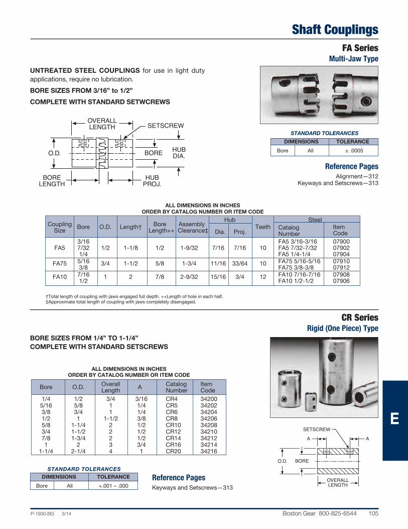
P-1930-BG 3/14 Boston Gear 800-825-6544 105
Shaft CouplingsFA Series
Multi-Jaw Type
STANDARD TOLERANCES
DIMENSIONS TOLERANCE
Bore All ± .0005
Reference PagesAlignment—312
Keyways and Setscrews—313
UNTREATED STEEL COUPLINGS for use in light duty
applications, require no lubrication.
BORE SIZES FROM 3/16” to 1/2”
COMPLETE WITH STANDARD SETWCREWS
OVERALLLENGTH
HUBDIA.BOREO.D.
HUBPROJ.
SETSCREW
BORELENGTH
ALL DIMENSIONS IN INCHESORDER BY CATALOG NUMBER OR ITEM CODE
Hub Steel Coupling Bore O.D. Length† Bore Assembly Teeth Catalog Item Size Length++ Clearance‡ Dia. Proj. Number Code
3/16 FA5 3/16-3/16 07900 FA5 7/32 1/2 1-1/8 1/2 1-9/32 7/16 7/16 10 FA5 7/32-7/32 07902 1/4 FA5 1/4-1/4 07904 FA75 5/16 3/4 1-1/2 5/8 1-3/4 11/16 33/64 10 FA75 5/16-5/16 07910 3/8 FA75 3/8-3/8 07912 FA10 7/16 1 2 7/8 2-9/32 15/16 3/4 12 FA10 7/16-7/16 07908 1/2 FA10 1/2-1/2 07906
†Total length of coupling with jaws engaged full depth. ++Length of hole in each half.‡Approximate total length of coupling with jaws completely disengaged.
SETSCREW
OVERALLLENGTH
AA
BOREO.D.
BORE SIZES FROM 1/4” TO 1-1/4”COMPLETE WITH STANDARD SETSCREWS
ALL DIMENSIONS IN INCHESORDER BY CATALOG NUMBER OR ITEM CODE
Overall Catalog Item
Bore O.D. Length
A Number Code
1/4 1/2 3/4 3/16 CR4 34200 5/16 5/8 1 1/4 CR5 34202 3/8 3/4 1 1/4 CR6 34204 1/2 1 1-1/2 3/8 CR8 34206 5/8 1-1/4 2 1/2 CR10 34208 3/4 1-1/2 2 1/2 CR12 34210 7/8 1-3/4 2 1/2 CR14 34212 1 2 3 3/4 CR16 34214 1-1/4 2-1/4 4 1 CR20 34216
STANDARD TOLERANCES DIMENSIONS TOLERANCE
Bore All +.001 – .000
Reference PagesKeyways and Setscrews—313
CR SeriesRigid (One Piece) Type
E

106 Boston Gear 800-825-6544 P-1930-BG 3/14
Shaft CouplingsFCP SeriesSleeve Type
MaterialsUrethane SleevesDelrin HubsAluminum Alloy Inserts
STANDARD TOLERANCES DIMENSIONS TOLERANCE
Bore All +.001 – .000
SPLINED HUBS AND URETHANE SLEEVE accommodate
misalignment to 5°.
SLEEVE STOCK available for producing special lengths.
NO LUBRICATION NEEDED
COMPLETE WITH SETSCREWS
SETSCREWBORE
H
INSERTHUB
E
O.D.
AL
116
A2
ALL DIMENSIONS IN INCHESORDER BY CATALOG NUMBER OR ITEM CODE
Complete Insert and Hub Sleeve Coupling Assembly Only Bore O.D. A E H L Setscrew
Catalog Item Catalog Item Catalog Item Number Code Number Code Number Code
.125 4 – 40 FCP21 – 1/8 54893 XFCP21 – 1/8 54903 .1875 37/64 7/32 7/16 9/16 15/16
6 – 32 FCP21 – 3/16 54894 XFCP21 – 3/16 54904 X5R21 – 16 54913
.250 FCP21 – 1/4 54895 XFCP21 – 1/4 54905 .3125 8 – 32 FCP23 – 5/16 54899 XFCP23 – 5/16 54909 .375 10 – 32 FCP23 – 3/8 54900 XFCP23 – 3/8 54910 .4375
1-5/64 3/8 11/16 1 1-9/16 1/4 – 20
FCP23 – 7/16 54901 XFCP23 – 7/16 54911 X5R23 – 32 54915
.500 FCP23 – 1/2 54902 XFCP23 – 1/2 54912
Load Data Sleeve Stock
HORSEPOWER RATINGS (MAXIMUM)AT 1750 RPM
Size Horsepower
FCP21 1/20 FCP23 1/2
ORDER BY CATALOG NUMBEROR ITEM CODE
Length Catalog Item
O.D. (Inches) Number Code
1/2 12
5R21 – 16S 54916 1 5R23 – 32S 54918
E

Universal Joints
P-1930-BG 3/14 Boston Gear 800-825-6544 107
J/JS SeriesPin and Block Type; Steel and Stainless Steel
Boston Gear precision machined J and JS Series Universal Joints are designed for connecting shafts at angles up to 30 degrees and speeds up to 2000 RPM. All sizes arestocked with both solid and bored hubs.
Joints J100 and J100B and larger are equipped with self-closing, ball valve oilers, creating an oil reservoir to provide enclosed lubrication.
The self-locking assembly ring on joints with 7/8” and larger hub diameter, fits intorecess provided in center bearing block and snaps around groove in small bearing pin— assuring locking of entire assembly allowing for quick and easy disassembly andreassembly.
Joints with 3/4” and smaller hub diameters are locked by riveting the small bearing pin.Joint covers (boots) keep dirt and moisture out and lubricants in.
SelectionTorque ratings may be calculated from data in tables. Thetables indicate the Rated Static Torque (Lb. Ins.) of alloy andstainless steel joints and Speed-Angle factors suggested forvarious operating conditions.
The approximate service torque rating of a particular jointis obtained by dividing the Rated Static Torque by the appropriate Speed-Angle factor.
Selecting a universal to satisfy a specified torque requirementis also made convenient with the data provided.
The designated torque load should be multiplied by the appropriate Speed-Angle factor to obtain an equivalent statictorque load.
A universal with a rated static torque equal to or greater thanthe calculated torque load would then be selected.
Example:A pair of universal joints are desired to transmit 1/2 HP fromone shaft running at 500 RPM to another located at an angleof 10 degrees (from a straight line).
The joints will be connected by an intermediate shaft andarranged to operate at equal angles of 5 degrees.A Speed-Angle factor of 9 is indicated in the table for an operating angle of 5 degrees and a speed of 500 RPM.
63025 x HP 63025 x 1/2Torque Load = = = 63 Lb. Ins. RPM 500
J100 size alloy steel or JS175 size stainless steel universalswould be suggested for this application.
SPEED-ANGLE FACTORS
Speed In Operating Angle – Degrees (Deviation From Straight Line)
RPM 0 1/2 1 2 3 4 5 6 8 10 12 15 20 25 30 2000 21 22 23.2 25.2 27.4 29.4 31.6 – – – – – – – – 1800 19 20 21.0 22.8 24.8 26.6 28.6 30.4 – – – – – – – 1600 17 17.8 18.8 20.4 22.2 23.8 25.6 27.2 – – – – – – – 1400 15 15.8 16.6 18.0 19.6 21.0 22.6 24.0 27 – – – – – – 1200 13 13.6 14.4 15.6 17.0 18.2 19.6 20.8 23.4 – – – – – – 1000 11 11.6 12.2 13.2 14.4 15.4 16.6 17.6 19.8 22 – – – – – 900 10 10.6 11.0 12.0 13.0 14.0 15.0 16.0 18.0 20 22 – – – – 800 9.0 9.4 10.0 10.8 11.8 12.6 13.6 14.4 16.2 18 19.8 – – – – 700 8.0 8.4 8.8 9.6 10.4 11.2 12.0 12.8 14.4 16 17.6 20 – – – 600 7.0 7.4 7.8 8.4 9.2 9.8 10.6 11.2 12.6 14 15.4 17.6 – – – 500 6.0 6.4 6.6 7.2 7.8 8.4 9.0 9.6 10.8 12 13.2 15.0 18 – – 400 5.0 5.2 5.6 6.0 6.6 7.0 7.6 8.0 9.0 10 11.0 12.6 15 17.6 – 300 4.0 4.2 4.4 4.8 5.2 5.6 6.0 6.4 7.2 8.0 8.8 10.0 12 14.0 16 200 3.0 3.2 3.4 3.6 4.0 4.2 4.6 4.8 5.4 6.0 6.6 7.6 9.0 10.6 12 100 2.0 2.2 2.2 2.4 2.6 2.8 3.0 3.2 3.6 4.0 4.4 5.0 6.0 7.0 8.0 50 1.5 1.6 1.7 1.8 2.0 2.2 2.2 2.4 2.8 3.0 3.4 3.8 4.6 5.2 6.0 25 1.3 1.3 1.4 1.5 1.6 1.8 1.9 2.0 2.2 2.6 2.8 3.2 3.8 4.4 5.0 10 1.1 1.2 1.2 1.3 1.4 1.5 1.7 1.8 2.0 2.2 2.4 2.8 3.4 3.8 4.4 0 1.0 1.1 1.1 1.2 1.3 1.4 1.5 1.6 1.8 2.0 2.2 2.6 3.0 3.6 4.0
ALLOY STEEL UNIVERSAL JOINTS
Catalog Number J37 J50 J62 J75 J87 J100 J112 J125 J150 J175 J200 J250 J300 J400 Torque – Lb. Ins. 20 80 166 320 370 600 670 1040 1680 2500 4400 7000 11,000 26,400
STAINLESS STEEL UNIVERSAL JOINTS
Catalog Number JS37 JS50 JS62 JS75 JS87 JS100 JS112 JS125 JS150 JS175 JS200 JS250 JS300 JS400 Torque – Lb. Ins. 6 24 50 96 110 180 200 310 500 750 1320 1900 3100 7360
RATED STATIC TORQUE (LB. INS.) STRAIGHT LINEE

108 Boston Gear 800-825-6544 P-1930-BG 3/14
Universal JointsJ/JS Series Bored and Solid HubsPin and Block Type; Steel and Stainless Steel
STANDARD TOLERANCES
DIMENSIONS TOLERANCE Steel Stainless Bore All ± .001 ±.001 Hub Dia. All +.000 –.003 ±.020Bore Length All ±1/16 ±1/64 Overall 1-3/4 - 4-1/4 ±1/64 ±1/64 Length 5 -10-5/8 ±1/32 ±1/32
Reference PagesLubrication—312Mounting—312
C B C
A
Steel Stainless Steel Universal Joints Boot Kits† Catalog Item Catalog Item
Bore** Bore Hub Overall Keyway Setscrew
Approx. Catalog† Item Number Code Number Code Length* Dia. Length Weight A B C Number Code Lbs. J37A-3/16 72467 - - 3/16 11/16 3/8 1-3/4 - 2-56NC .04 J37B 08426 JS37B 08472 3/16 11/16 3/8 1-3/4 - - .04 1-1/32 1-1/32 9/32 UB37 47602 J37 08400 JS37 08452 - - 3/8 1-3/4 - - .05 J50A-1/4 72468 - - 1/4 3/4 1/2 2 - 4-40NC .08 J50B 08428 JS50B 08474 1/4 3/4 1/2 2 - - .08 1-1/4 1-5/16 11/32 UB50 47603 J50 08402 JS50 08454 - - 1/2 2 - - .10 J62A-5/16 72469 - - 5/16 13/16 5/8 2-1/4 3/32x3/64 10-32NF .14 J62B 08430 JS62B 08476 5/16 13/16 5/8 2-1/4 - - .14 1-1/2 1-7/16 13/16 UB62 47604 J62 08404 JS62 08456 - - 5/8 2-1/4 - - .18 J75A-3/8 72470 - - 3/8 31/32 3/4 2-11/16 3/32x3/64 10-32NF .24 J75B 08432 JS75B 08478 3/8 31/32 3/4 2-11/16 - - .24 1-3/4 1-9/16 9/16 UB75 47605 J75 08406 JS75 08458 - - 3/4 2-11/16 - - .30 J87A-7/16 72471 -- 7/16 1-1/32 7/8 3 3/32x3/64 10-32NF .31 J87B 08434 JS87B 08480 7/16 1-1/32 7/8 3 - - .31 2 1-13/16 19/32 UB87 47606 J87 08408 JS87 08460 - - 7/8 3 - - .45 J100A-1/2 72472 - - 1/2 1-3/16 1 3-3/8 1/8x1/16 1/4-20NC .50 J100B 08436 JS100B 08482 1/2 1-3/16 1 3-3/8 - - .50 2-1/4 2-1/8 5/8 UB100 47607 J100 08410 JS100 08462 - - 1 3-3/8 - - .66 J112A-9/16 72473 - - 9/16 1-7/32 1-1/8 3-1/2 1/8x1/16 1/4-20NC .69 J112B 72474 JS112B 72483 9/16 1-7/32 1-1/8 3-1/2 - - .69 2-9/16 2-7/16 17/32 UB112 72491 J112 72475 JS112 72484 - - 1-1/8 3-1/2 - - .88 J125A-5/8 72476 -- 5/8 1-1/4 1-1/4 3-3/4 3/16x3/32 5/16-18NC .88 J125B 08438 JS125B 08484 5/8 1-1/4 1-1/4 3-3/4 - - .88 2-7/8 2-3/4 1/2 UB125 47608 J125 08412 JS125 08464 - - 1-1/4 3-3/4 - - 1.15 J150A-3/4 72477 - - 3/4 1-11/32 1-1/2 4-1/4 3/16x3/32 5/16-18NC 1.44 J150B 08440 JS150B 08486 3/4 1-11/32 1-1/2 4-1/4 - - 1.44 3-1/4 3-1/4 1/2 UB150 47609 J150 08414 JS150 08466 - - 1-1/2 4-1/4 - - 1.81 J175A-7/8 72478 - - 7/8 1-9/16 1-3/4 5 3/16x3/32 5/16-18NC 2.31 J175B 08442 JS175B 08488 7/8 1-9/16 1-3/4 5 - - 2.31 3-5/8 3-3/4 5/8 UB175 47610 J175 08416 JS175 08468 - - 1-3/4 5 - - 2.86 J200A-1 72479 - - 1 1-5/8 2 5-7/16 1/4x1/8 3/8-16NC 3.31 J200B 08444 JS200B 08490 1 1-5/8 2 5-7/16 - - 3.31 4-1/2 4-3/16 5/8 UB200 47611 J200 08418 JS200 08470 - - 2 5-7/16 - - 4.06 J250A-1-1/4 72480 - - 1-1/4 2-3/32 2-1/2 7 1/4x1/8 3/8-16NC 6.81 J250B 08446 JS250B 72485 1-1/4 2-3/32 2-1/2 7 - - 6.81 5-1/2 4-7/8 1-1/16 UB250 47612 J250 08420 JS250 72486 - - 2-1/2 7 - - 8.25 J300A-1/1/2 72481 - - 1-1/2 2-27/32 3 9 3/8x3/16 1/2-13NC 12.5 J300B 08448 JS300B 72487 1-1/2 2-27/32 3 9 - - 12.5 6 5-5/8 1-11/16 UB300 47613 J300 08422 JS300 72488 - - 3 9 - - 15.25 J400A-2 72482 - - 2 3-1/8 4 10-5/8 1/2x1/4 1/2-13NC 25.8 J400B 08450 JS400B 72489 2 3-1/8 4 10-5/8 - - 25.8 6-7/8 6-5/8 2 UB400 47614 J400 08424 JS400 72490 - - 4 10-5/8 - - 31.3
*Approximate Hub Projection†Each Kit contains (2) Boots and (4) Ties together with complete instructions for installation and lubrication.**Style A includes bore, keyway and setscrew. Style B includes bore only. Units without an A & B letter have a solid bore.
ALL DIMENSIONS IN INCHESORDER BY CATALOG NUMBER OR ITEM CODE
OVERALL LENGTH
BORE DIA.
BORELENGTH
OVERALLLENGTH
2
OVERALLLENGTH
2
HUBDIA.
E

Universal Joints
P-1930-BG 3/14 Boston Gear 800-825-6544 109
UJNS/UJNL Series BOS-Trong®
Cast/Forged SteelA BOS-trong joint is composed of two yokes and a center kit. BOS-trongjoints may be purchased assembled, or as separate yokes and center kits.Individually boxed.AVAILABLE IN TWO SIZESEQUIPPED WITH NEEDLE BEARINGSPRECISION MACHINED FOR LONG, SMOOTH OPERATIONCONTINUOUS OR INTERMITTENT SERVICEHIGH CAPACITY WITH MINIMUM SWING DIAMETERSAVAILABLE WITH ROUND, SQUARE OR HEXAGON HOLESCOMPLETE WITH KEYWAY AND SETSCREWREPLACEABLE CENTER KITSFITTING FOR LUBRICATIONUJNS CAST STEELUJNL FORGED STEEL
SelectionUniversal Joints are used in many different types of applications and under a wide variety of operating conditions. No convenientmethod can be presented for determining ratings for all possible circumstances. Performance will be affected by vibration, shockloading, high temperature, dusty environment, etc.
The simplest solution to this problem is to provide approximate ratings of universal joints operating at various angles and speedsunder normal service conditions.
The suggested ratings are for general use in applications where two joints are arranged at equal angles with the bearing pins of theintermediate yokes in line with each other.
Service torque ratings of the two sizes of BOS-trong Needle Bearing universals are listed in tables. Ratings for intermediate speedsand/or angles not shown may be found by interpolation.
APPROXIMATE TORQUE RATINGS (LB. INS.)
UJNS Series UJNL Series Speed Operating Angle*—Degrees (Deviation from Straight Line) Operating Angle†—Degrees (Deviation from Straight Line) RPM Up to Up to 3° 5° 8° 12° 20° 30° 3° 5° 8° 12° 20° 30°
1800 610 515 440 — — — 845 710 610 — — — 1200 700 590 505 435 — — 965 815 695 600 — — 900 770 650 555 480 365 — 1060 895 765 660 500 — 600 880 740 635 545 415 260 1210 1020 875 755 575 355 300 1110 935 800 690 525 325 1530 1290 1100 950 725 450 200 1270 1070 915 790 600 370 1750 1480 1260 1090 825 515 100 1600 1350 1150 995 755 470 2210 1860 1590 1370 1040 645 50 2020 1700 1450 1250 950 590 2780 2350 2000 1730 1310 815 25 2540 2140 1830 1580 1200 745 3500 2960 2530 2180 1650 1020 10 3450 2900 2480 2140 1630 1010 4760 4010 3430 2960 2250 1390
Load Data
NON-OPERATING FLEX-ANGLE—90° *Maximum Angles (Momentary)—45°†Maximum Angle (Momentary)—35° E

Universal JointsUJNS/UJNL Series BOS-Trong®
Cast/Forged Steel
110 Boston Gear 800-825-6544 P-1930-BG 3/14
DIMENSION IN INCHES
STANDARD TOLERANCES DIMENSIONS TOLERANCE
Bore All ± .001
Hub Dia. All + .000 – .002
Reference PagesLubrication—312Mounting—312
ORDERING INFORMATIONJoints can also be ordered in variouscombinations of round, square or hexholes. To order the combinationdesired, specify “UJNS” or “UJNL” andhole size and type as listed in table ofYokes, Page 111. Use “S” for squareand “H” for hexagon.
All joints have round holes with standard keyways and 3/8—16 hex socketsetscrews.
Overall Bore Hub Dia. App. Wt. Catalog Item Length Hub-A Hub-B Hub-A Hub-B (Lbs.) Number CodeUJNS SERIES SWING DIAMETER—2-1/2” 5/8 UJNS 10-10 17300 3/4 UJNS 10-12 17302 13/16 UJNS 10-13 17304 5 5/8 7/8 1-5/8 1-5/8 2 UJNS 10-14 17306 15/16 UJNS 10-15 17308 1 UJNS 10-16 17310 1-1/8 2-1/4 UJNS 10-18 17312 3/4 UJNS 12-12 17314 13/16 UJNS 12-13 17316 7/8
1-5/8 1-5/8 2 UJNS 12-14 17318
5 3/4 15/16 UJNS 12-15 17320
1 UJNS 12-16 17322 1-1/8 2-1/4 UJNS 12-18 17324 13/16 UJNS 13-13 17326 7/8
1-5/8 UJNS 13-14 17328
5 13/16 15/16 1-5/8 2 UJNS 13-15 17330 1 UJNS 13-16 17332 1-1/8 2-1/4 UJNS 13-18 17334 7/8 UJNS 14-14 17336 5 7/8 15/16 1-5/8 1-5/8 2 UJNS 14-15 17338 1 UJNS 14-16 17340 1-1/8 2-1/4 UJNS 14-18 17342 15/16 1-5/8 UJNS 15-15 17344 5 15/16 1 1-5/8 2 UJNS 15-16 17346 1-1/8 2-1/4 UJNS 15-18 17348 5 1 1 1-5/8 1-5/8 2 UJNS 16-16 17350 1-1/8 2-1/4 UJNS 16-18 17352 5 1-1/8 1-1/8 2-1/4 2-1/4 3 UJNS 18-18 17498UJNL SERIES SWING DIAMETER—2-3/4” 1 2 UJNL 16-16 17354 1-1/8 UJNL 16-18 17356 1-3/16 UJNL 16-19 17358 5-1/2 1 1-1/4 2 2-1/4 3-3/4 UJNL 16-20 17360 1-3/8 UJNL 16-22 17362 1-7/16 UJNL 16-23 17364 1-1/2 UJNL 16-24 17366 1-1/8 UJNL 18-18 17368 1-3/16 UJNL 18-19 17370 5-1/2 1-1/8 1-1/4 2-1/4 2-1/4 3-3/4 UJNL 18-20 17372 1-3/8 UJNL 18-22 17374 1-7/16 UJNL 18-23 17376 1-1/2 UJNL 18-24 17378 1-3/16 2 UJNL 19-19 17380 1-1/4 UJNL 19-20 17382 5-1/2 1-3/16 1-3/8 2-1/4 2-1/4 3-1/4 UJNL 19-22 17384 1-7/16 UJNL 19-23 17386 1-1/2 UJNL 19-24 17388 1-1/4 2 UJNL 20-20 17390 5-1/2 1-1/4
1-3/8 2-1/4 2-1/4 3-1/4
UJNL 20-22 17392 1-7/16 UJNL 20-23 17394 1-1/2 UJNL 20-24 17396 1-3/8 UJNL 22-22 17398 5-1/2 1-3/8 1-7/16 2-1/4 2-1/4 3-1/4 UJNL 22-23 17400 1-1/2 UJNL 22-24 17402 5-1/2 1-7/16 1-7/16 2-1/4 2-1/4 3-1/4 UJNL 23-23 17404 1-1/2 UJNL 23-24 17406 5-1/2 1-1/2 1-1/2 2-1/4 2-1/4 3-1/4 UJNL 24-24 17408
HUBDIA.BORE
SETSCREW
OVERALLLENGTH
KEYWAY
E

Universal JointsUJS/UJL SeriesCast/Forged Steel
P-1930-BG 3/14 Boston Gear 800-825-6544 111
STANDARD TOLERANCES
DIMENSION TOLERANCE
Round +.000 – +.002
Bore Square 3/4–13/16 +.000–+.002 7/8 –1-1/2 +.001 +.003 Hexagon +.002 +.004
YokesThese yokes are for assembly with UJSC Center Kits.All yokes are furnished with 3/8–16 hex socket setscrew.UJS14H is 1/8 NPT straight.
HUBDIA.BORE
KEYWAY
DIM.ACROSS
FLATSA
Center Kits Double Yokes
ALL DIMENSIONS IN INCHES
*Center Kits include 1 cross, 4 bearings, 4 cork washers and 4 lock rings.
A
Round Bores Square Bores Hexagon Bores
BoreHubDia.
KeywaySetscrewLocation
Approx.Weight(Lbs.)
CatalogNumber
ItemCode
Dim.AcrossFlats
HubDia.
Approx.Weight(Lbs.)
CatalogNumber
ItemCode
CatalogNumber
ItemCode
UJS Series
2-1/2
.625
1.63
3/16x3/32(4)
3/4
UJS10 17410 — — — — — — —.750 (4) UJS12 17412 .750
1.633/4
UJS12S 17438 — —.813 (5) UJS13 17414 .813 UJS13S 17440 — —.875 (1) (4) UJS14 17416 .875 (7)
2.25
UJS14S 17442 UJS14H (7) 17454.938 1/4x1/8 (4) UJS15 17418 .938
1-1/4— — — —
1.000 (1) (4) UJS16 17420 1.000(7) UJS16S 17446 — —1.125 2.25 (2) (4) 1-1/4 UJS18 17422 1.126 UJS18S 17448 UJS18H 17456
UJL Series
2-3/4
1.000 2.00 1/4x1/8 (3) (4) 1-1/2 UJL16 17424 1.000 2.00 1-1/2 UJL16S 17450 — —1.125
2.25
1/4x1/8(5)
1-1/4
UJL18 17426 1.126 2.25 1-1/2 UJL18S 17452 UJL18H 174581.1875 UJL19 174281.250 UJL20 174301.375 5/16x5/32 UJL22 174321.4375
3/8x3/16UJL23 17434
1.500 (4)(6) UJL24 17436
(1) Two keyways 180° apart, 3/16x3/32 and 1/4x1/8(2) Two keyways 180° apart, 1/4x1/8 and 5/16x5/32(3) Located 90° from shown(4) Located as shown(5) Located 180° from shown(6) Additional setscrew over keyway(7) Has both .875 and 1.000 square bores @ 45°
ALL DIMENSIONS IN INCHES
Center Kits* Double Yokes Approx. Maximum Approx. Weight Catalog Item Operating Weight Catalog Item A B C D (Lbs.) Number Code J Angle (Lbs.) Number Code
UJS Series UJS Series Forged 1-61/64 35/64 19/32 31/32 1/2 UJSC 17464 2-1/2 15° 1 UJSD 17460UJL Series UJL Series Forged – 2 piece Welded Construction 2-5/16 .644 5/8 1-1/16 3/4 UJLC 17466 4-7/16 35° 2-1/4 UJLD 17462
E

Universal JointsJP Series Single and DoubleMolded Type
112 Boston Gear 800-825-6544 P-1930-BG 3/14
STANDARD TOLERANCES DIMENSIONS TOLERANCE
Bore All + .001 – .000
MOLDED DELRIN BODY provides vibration dampening and electrical insulation.
MAX. ANGULAR DISPLACEMENT — Single 45° — Double 90°
MAX. AMBIENT TEMPERATURE — 180°F
COMPLETE WITH SETSCREWS
Reference PagesMounting — 312
MaterialsDelrin BodyNickel Plated Brass Spider and Insert
BRASSSPIDER
L
(2) SETSCREWSEACH END
BORE
C
O.D.F
Double Only Bore Max.
Single Double
Bore Depth O.D. C L F Parallel
Setscrew Catalog Item Catalog Item (Typical) Single Double Offset Number Code Number Code
1/8 .39 1/4 .27 1-3/64 1-23/64 5/16 .22 #4 – 40 JP25 – 1/8* 54194 JPD25 – 1/8 54202 1/8 .52 3/8 .41 1-31/64 2 17/32 .36 #4 – 40 JP37 – 1/8* 54195 JPD37 – 1/8 54203 3/16 JP37 – 3/16 54196 JPD37 – 3/16 54204 3/16 .63 1/2 .54 1-13/16 2-7/16 5/8 .43 #6 – 32 JP50 – 3/16 54197 JPD50 – 3/16 54205 1/4 JP50 – 1/4 54198 JPD50 – 1/4 54206 1/4 JP62 – 1/4 54199 JPD62 – 1/4 54207 5/16 .86 5/8 .68 2-41/64 3-33/64 7/8 .61 #8 – 32 JP62 – 5/16 54200 JPD62 – 5/16 54208 3/8 JP62 – 3/8 54201 JPD62 – 3/8 54209* One setscrew each end.
LOAD DATA Maximum Torque† Basic (Lb. Ins.) Size Single Double
25 5 2.5 37 16 7 50 26 12 62 60 47†This is the ultimate or breaking torque for static, zero angle conditions.Actual operating conditions will dictate use of significantly lower values.
ALL DIMENSIONS IN INCHESORDER BY CATALOG NUMBER OR ITEM CODE
INSERT
BRASSSPIDER
L
(2) SETSCREWSBORE
C
O.D.
EACH END (SEE NOTE)
SINGLE
DOUBLE
E

Universal JointsJPE Series With Slide Extension
Molded Type
P-1930-BG 3/14 Boston Gear 800-825-6544 113
STANDARD TOLERANCES DIMENSIONS TOLERANCE
Bore All + .001 – .000
MOLDED DELRIN BODY — provides vibration dampening and electrical insulation.
MAX. ANGULAR DISPLACEMENT — Single 45° — Double 90°
MAX. AMBIENT TEMPERATURE — 180°F
COMPLETE WITH SETSCREWS
Reference PagesMounting — 312
MaterialsDelrin BodyNickel Plated Brass Spider and Insert
BRASSSPIDERS
K IN CLOSED POSITION
(2) SETSCREWSEACH END(SEE NOTE)
BORE
A
O.D. F HG
SQ.
D
C IN CLOSED POSITIONB
J
Bore Depth G Catalog Item
Bore
(Typical) O.D. A B C D E F
(Sq.) H J K
Setscrew
Number Code
1/8 .52 3/8 .41 .74 2-59/64 1-1/8 – 1-47/64 3/16 23/64 2-43/64 4-13/32 #4 – 40 JPE37 – 1/8 54210 3/16 JPE37 – 3/16 54211 3/16 .63 1/2 .54 .91 2-23/64 1-1/8 3/8 1-34/64 3/16 23/64 2-9/16 4-11/64 #6 – 32 JPE50 – 3/16 54212 1/4 JPE50 – 1/4 54213
LOAD DATA Maximum Recommended
Basic Torque (Lb. Ins.)
Size
Closed Open
JPE37 8 5
JPE50 14 10
†This is the ultimate or breaking torque for static, zero angle conditions. Actualoperating conditions will dictate use of significantly lower values.
ALL DIMENSIONS IN INCHESORDER BY CATALOG NUMBER OR ITEM CODE
E

Setscrew CollarsSC/SSC SeriesSteel and Stainless Steel
114 Boston Gear 800-825-6544 P-1930-BG 3/14
SETSCREWS
BORE OUTSIDEDIA.
WIDTH
STANDARD TOLERANCES DIMENSIONS TOLERANCE
Bore
1/8-1 + .001 + .003
1-1/16-3 +.001 +.004
MaterialsStainless Steel—Type 303 Austenitic.Steel—Low Carbon, Zinc plated finish.
STEEL BORE SIZES FROM 1/8” TO 3”STAINLESS STEEL BORE SIZES FROM 1/8” TO 2”STAINLESS STEEL COLLARS ARE CORROSION-RESISTANT AND NON-MAGNETIC suitable for temperatures up to 800°F. Ideal for applicationsrequiring hygienic cleanliness.ALL COLLARS COMPLETE WITH STANDARD HOLLOW POINTSETSCREWS.
ALL DIMENSIONS IN INCHESORDER BY CATALOG NUMBER OR ITEM CODE
Alloy Steel Stainless Steel Outside Catalog Item Catalog Item Bore
Diameter Width
Number Code Number Code 1/8 3/8 1/4 SC12 67697 SSC12 67740 3/16 7/16 1/4 SC18 67698 SSC18 67741 1/4 1/2 5/16 SC25 67699 SSC25 67742 5/16 5/8 11/32 SC31 67700 SSC31 67743 3/8 3/4 3/8 SC37 67701 SSC37 67744 7/16 7/8 7/16 SC43 67702 — — 1/2 1 7/16 SC50 67703 SSC50 67745 9/16 SC56 67704 — — 5/8 1-1/8 1/2 SC62 67705 SSC62 67746 11/16 1-1/4 9/16 SC68 67706 — — 3/4 SC75 67707 SSC75 67747 13/16 1-1/4 9/16 SC81 67708 — — 7/8 1-1/2 9/16 SC87 67709 SSC87 67748 15/16 1-5/8 9/16 SC93 67710 — — 1 1-1/2 5/8 SC100 67711 SSC100 67749 1-1/16 1-3/4 5/8 SC106 67712 — — 1-1/8 SC112 67713 SSC112 67784 1-3/16 2 11/16 SC118 67714 — — 1-1/4 SC125 67715 SSC125 67785 1-5/16 2-1/8 11/16 SC131 67716 — — 1-3/8 3/4 SC137 67717 — — 1-7/16 2-1/4 3/4 SC143 67718 — — 1-1/2 SC150 67719 SSC150 67788 1-9/16 SC156 67720 — — 1-5/8 2-1/2 13/16 SC162 67721 — — 1-11/16 SC168 67722 — — 1-3/4 SC175 67723 SSC175 67789 1-13/16 2-5/8 7/8 SC181 67724 — — 1-7/8 SC187 67725 — — 1-15/16 SC193 67726 — — 2 3 7/8 SC200 67727 SSC200 67790 2-1/8 SC212 67728 — — 2-3/16 SC218 67729 — — 2-1/4 3-1/4 15/16 SC225 67730 — — 2-5/16 SC231 67731 — — 2-3/8 SC237 67732 — — 2-7/16 3-1/2 1 SC243 67733 — — 2-1/2 SC250 67734 — — 2-9/16 3-3/4 1 SC256 67735 — — 2-11/16 4 1-1/8 SC268 67736 — — 2-3/4 SC275 67737 — — 2-15/16 4 1-1/8 SC293 67738 — — 3 SC300 67739 — —
E

Clamping CollarsCSC/CSSC Series
Threaded Type; Steel and Stainless Steel
P-1930-BG 3/14 Boston Gear 800-825-6544 115
BORE
OUTSIDEDIA. WIDTH
CLAMP SCREW
MaterialsSteel—Low Carbon,Black Oxide Finish
Stainless—Type 303 Austenitic
DESIGN PROVIDES CONVENIENT SETTING, ADJUSTING AND REMOVALprevents shaft damageOSHA CONFORMANCE collars have completely recessed screw head.BORE THREADS FROM 10–32 TO 200–12
ORDER BY CATALOG NUMBER OR ITEM CODE
Steel Stainless Steel Bore Outside Clamp Catalog Item Catalog Item Thread Dia.
Width Screws Number Code Number Code
10-32 11/16 1/4 4-40 CSC10-32 49237 — — 1/4-20 CSC25-20 49238 CSSC25-20 49265 1/4-28 13/16 1/4 4-40 CSC25-28 49239 — — 5/16-18 CSC31-18 49240 — — 5/16-24 CSC31-24 49241 — — 3/8-16 1-1/16 5/16 6-32 CSC37-16 49242 CSSC37-16 49269 3/8-24 CSC37-24 49243 CSSC37-24 49270 1/2-13 1-1/4 3/8 8-32 CSC50-13 49244 CSSC50-13 49271 1/2-20 CSC50-20 49245 CSSC50-20 49272 5/8-11 1-1/2 13/32 10-32 CSC62-11 49246 CSSC62-11 49273 5/8-18 CSC62-18 49247 CSSC62-18 49274 3/4-10 1-3/4 1/2 1/4-28 CSC75-10 49248 CSSC75-10 49275 3/4-16 CSC75-16 49249 CSSC75-16 49276 7/8-9 1-7/8 1/2 1/4-28 CSC87-9 49250 — — 7/8-14 CSC87-14 49251 — — 1-8 2 1/2 1/4-28 CSC100-8 49252 CSSC100-8 49279 1-14 CSC100-14 49253 CSSC100-14 49280 1-1/8-7 2-1/8 1/2 1/4-28 CSC125-7 49256 — —1-1/8-12 CSC112-12 49255 — — 1-1/4-7 2-1/4 1/2 1/4-28 CSC125-7 49256 — —1-1/4-12 CSC125-12 49257 CSSC125-12 49284 1-1/2-6 2-1/2 1/2 1/4-28 CSC150-6 49258 — —1-1/2-12 CSC150-12 49259 — —1-3/4-16 3 5/8 5/16-24 CSC175-16 49260 — — 2-12 3-1/4 5/8 5/16-24 CSC200-12 49261 — —
E

Clamping CollarsCSC/CSSC/CASC Series1 Piece Type Steel, Stainless Steel and Aluminum
116 Boston Gear 800-825-6544 P-1930-BG 3/14
BORE
OUTSIDEDIA. WIDTH
CLAMP SCREW
MaterialsSteel—Low Carbon Black Oxide Finish Stainless—Type 303Austenitic
Load DataCapacity is based on a standard steel,one-piece collar mounted with recommended screw torque on a lightlyoiled shaft. Capacity is load to movecollar .010”. Data shown is for guidanceonly. In applications involving control ofaxial loads, capacity should be determined experimentally on actualparts involved.
DESIGN PROVIDES CONVENIENT SETTING, ADJUSTING AND REMOVALprevents shaft damageOSHA CONFORMANCE collars have completely recessed screw head.BORE THREADS FROM 1/8” TO 3”
ALL DIMENSIONS IN INCHESORDER BY CATALOG NUMBER OR ITEM CODE
Steel Stainless Steel Aluminum Bore O.D. Width Clamp Catalog Item Catalog Item Catalog Item Screws Number Code Number Code Number Code 1/8 CSC12 49000 CSSC12 49094 — — 3/16 13/16 1/4 4-40 CSC18 49001 CSSC18 49095 CASC18 49048 1/4 CSC25 49002 CSSC25 49096 CASC25 49049 5/16 CSC31 49003 CSSC31 49097 CASC31 49050 3/8 1-1/16 5/16 6-32 CSC37 49004 CSSC37 49098 CASC37 49051 7/16 CSC43 49005 CSSC43 49099 — — 1/2 1-1/4 3/8 8-32 CSC50 49006 CSSC50 49100 CASC50 49053 9/16 CSC56 49007 CSSC56 49101 CASC56 49054 5/8 1-1/2 13/32 10-32 CSC62 49008 CSSC62 49102 CASC62 49055 11/16 CSC68 49009 — — — — 3/4 1-3/4 CSC75 49010 CSSC75 49104 CASC75 49057 13/16 CSC81 49011 — — — — 7/8 1-7/8 CSC87 49012 CSSC87 49106 CASC87 49059 15/16 CSC93 49013 CSSC93 49107 — — 1 2 CSC100 49014 CSSC100 49108 CASC100 49061 1-1/16 CSC106 49015 CSSC106 49109 — — 1-1/8 2-1/8
1/2 1/4-28 CSC112 49016 CSSC112 49110 CASC125 49065 1-3/16 CSC118 49017 CSSC118 49111 — — 1-3/8 2-3/8 CSC137 49020 — — — — 1-5/16 CSC143 49021 CSSC143 49115 — — 1-1/2 2-1/2 CSC150 49022 CSSC150 49116 CASC150 49069 1-9/16 CSC156 49023 — — — — 1-5/8 CSC162 49024 — — — —1-11/16 3 CSC168 49025 — — — — 1-3/4 CSC175 49026 — — CASC175 49073 1-7/8 CSC187 49028 — — — —1-15/16 3-1/4 5/8 5/16-24 CSC193 49029 CSSC193 49123 — — 2 CSC200 49030 CSSC200 49124 CASC200 49077 2-3/16 CSC218 49033 — — — — 2-1/4 3-1/2 CSC225 49034 — — — — 2-3/8 CSC237 49036 — — — — 2-7/16 4 CSC243 49037 — — — — 2-1/2 CSC250 49038 — — — — 2-5/8 CSC262 49040 — — — —2-11/164-1/4 3/4 3/8-24 CSC268 49041 — — — — 2-3/4 CSC275 49042 — — — — 2-7/8 CSC287 49044 — — — —2-15/16 4-1/2 CSC293 49045 — — — — 3 CSC300 49046 — — — —
STANDARD TOLERANCES DIMENSIONS TOLERANCE
Bore All + .003 – .000
DIMENSION IN INCHES
Recommended Axial Load Screw Torque Bore Capacity Screw (Lb. Ins.) (Lbs.) Size Stainless Steel Steel 1/8-5/16 400 4-40 20 16 3/8-7/16 600 6-32 30 24 1/2-9/16 1400 8-32 55 35 5/8-11/16 1800 10-32 90 723/4-1-9/16 4000 1/4-28 220 1701-5/8-2-3/8 6500 5/16-24 435 340 2-7/16-3 8500 3/8-24 710 550
E

Clamping Collars2SC/2SSC Series
2 Piece Type Steel, Stainless Steel and Aluminum
P-1930-BG 3/14 Boston Gear 800-825-6544 117
BORE
OUTSIDEDIA. WIDTH
CLAMP SCREWS
MaterialsSteel—Low Carbon, Black Oxide Finish
Stainless—Type 303 Austenitic
Load DataCapacity is based on a standard steel,
one-piece collar mounted with recommended screw torque on a lightly
oiled shaft. Capacity is load to movecollar .010”. Data shown is for guidanceonly. In applications involving control of
axial loads, capacity should be determined experimentally on actual
parts involved.
DESIGN PROVIDES CONVENIENT SETTING, ADJUSTING AND REMOVALprevents shaft damageOSHA CONFORMANCE collars have completely recessed screw head.BORE THREADS FROM 1/4” TO 3”
ALL DIMENSIONS IN INCHESORDER BY CATALOG NUMBER OR ITEM CODE
Steel Stainless Steel Bore O.D. Width Clamp Catalog Item Catalog Item Screws Number Code Number Code 1/4 13/16 1/4 4-40 2SC25 49143 2SSC25 49190 5/16 2SC31 49144 2SSC31 49191 3/8 1-1/16 5/16 6-32 2SC37 49145 2SSC37 49192 7/16 2SC43 49146 2SSC43 49193 1/2 1-1/4 3/8 8-32 2SC50 49147 2SSC50 49194 9/16 2SC56 49148 2SSC56 49195 5/8 1-1/2 13/32 10-32 2SC62 49149 2SSC62 49196 11/16 2SC68 49150 2SSC68 49197 3/4 1-3/4 2SC75 49151 2SSC75 49198 13/16 2SC81 49152 — — 7/8 1-7/8 2SC87 49153 2SSC87 49200 15/16 2SC93 49154 1 2 2SC100 49155 2SSC100 49202 1-1/16 2SC106 49156 2SSC106 49203 1-1/8 2-1/8 1/2 1/4-28 2SC112 49157 2SSC112 49204 1-3/16 2SC118 49158 2SSC118 49205 1-1/4 2-1/4 2SC125 49159 2SSC125 49206 1-5/16 2SC131 49160 2SSC131 49207 1-3/8 2-3/8 2SC137 49161 — — 1-7/16 2SC143 49162 2SSC143 49209 1-1/2 2-1/2 2SC150 49163 2SSC150 49210 1-9/16 2SC156 49164 — — 1-5/8 2SC162 49165 — — 1-11/16 3 2SC168 49166 — — 1-3/4 2SC175 49167 — — 1-13/16 — — — — 1-7/8 2SC187 49169 2SSC187 49216 1-15/16 3-1/4 2SC193 49170 2SSC193 49217 2 2SC200 49171 2SSC200 49218 2-1/16 — — — — 2-1/8 2SC212 49173 — — 2-3/16 3-1/2 2SC218 49174 — — 2-1/4 2SC225 49175 — — 2-3/8 2SC237 49177 — — 2-7/16 4 2SC243 49178 — — 2-1/2 2SC250 49179 — — 2-5/8 2SC262 49181 — — 2-11/16 4-1/4 3/4 3/8-24 2SC268 49182 — — 2-3/4 2SC275 49183 — — 2-7/8 2SC287 49185 — — 2-15/16 4-1/2 2SC293 49186 — — 3 2SC300 49187 — —
STANDARD TOLERANCES DIMENSIONS TOLERANCE
Bore All + .003 – .000
DIMENSION IN INCHES
Recommended Axial Load Screw Torque Bore Capacity Screw (Lb. Ins.) (Lbs.) Size Stainless Steel Steel 1/8-5/16 400 4-40 20 16 3/8-7/16 600 6-32 30 24 1/2-9/16 1400 8-32 55 35 5/8-11/16 1800 10-32 90 723/4-1-9/16 4000 1/4-28 220 1701-5/8-2-3/8 6500 5/16-24 435 340 2-7/16-3 8500 3/8-24 710 550
1/2
5/8 5/16-24
3/4 3/8-24
1/4-28
E

118 Boston Gear 800-825-6544 P-1930-BG 3/14
Thrust WashersSteel and Stainless Steel
HARDENED AND GROUND STEEL BORE SIZES FROM 3/16” TO 2”STAINLESS STEEL BORE SIZES FROM 3/16” TO 1/2”
STANDARD TOLERANCES DIMENSIONS TOLERANCE
Bore
06700 Series + .0015 + .0070
18000 Series + .002 + .007
O.D.
06700 Series + .000 - .005
18000 Series ± .030
Thickness All +.000 - .005
Outside Thick- Catalog Bore Diameter ness Number
HARDENED STEEL
9/32 1/16 18800 3/32 18802 3/16 3/8 1/16 18804 3/32 18806 7/16 1/16 06724* 1/2 1/16 18808 1/4 3/32 18810 9/16 1/16 06726* 5/64 06728* 5/16 5/8 1/16 18812 1/8 18814 5/8 1/16 18816 3/8 1/8 18818 11/16 3/32 06730* 7/16 7/8 1/16 18820 5/32 18822 3/4 1/16 18824 1/8 18826 1/2 7/8 1/8 06734* 1-1/8 1/16 18828 5/32 18830 1-1/4 3/16 18832 9/16 1-3/8 3/32 18834 3/16 18836 25/32 1/16 18838 1/8 18840 1-1/4 3/32 18842 5/8 3/16 18844 1-3/8 3/16 18846 1-1/2 3/32 18848 3/16 18850 1-3/4 3/16 18852 1 3/32 18854 1-5/16 3/32 18856 3/16 18858 3/4 1-5/8 1/8 18860 3/16 18862 1-3/4 3/16 18864 2 3/16 18866
Outside Thick- Catalog Bore Diameter ness Number
HARDENED STEEL
1-3/16 3/32 18868 7/8 2 1/8 18870 2 3/16 18872 2-1/4 3/16 18874 7/16 13/16 3/32 06732*
1-9/16 1/8 18876
3/16 18878
2 1/8 18880
1 3/16 18882
2-1/4 9/64 18884
3/16 18886 2-1/2 1/4 188881-1/16 2-1/2 1/4 18890 1-1/8 2-1/2 1/4 188941-3/16 2 3/16 18896
2 9/64 18898
3/16 18922 2-7/16 9/64 18900 1-1/4 1/4 18924 2-3/4 9/64 18902 3 1/4 189041-5/16 2-3/4 1/4 18906 1-3/8
3 5/32 18908
1/4 18910
3 5/32 18912
1-1/2 1/4 18914 3-1/4 1/8 18916 2
4 5/32 18918
5/16 18920STAINLESS STEEL†
3/16 7/16 1/16 06760 1/4 9/16 1/16 06762 5/16 5/8 5/64 06764 3/8 11/16 3/32 06766 1/2 7/8 1/8 06770
*These washers also listed with AO Bearings.†These washers also listed with SAO Bearings.
ALL DIMENSIONS IN INCHESORDER BY CATALOG NUMBER OR ITEM CODE
E

Bushings
P-1930-BG 3/14 Boston Gear 800-825-6544 119
Soft Steel
ALL DIMENSIONS IN INCHESORDER BY CATALOG NUMBER
Outside Thick- Catalog Bore Diameter ness Number 1/4 18510 3/16 5/16 5/8 18512 3/8 18516 5/16 5/8 18514 1/4
3/8 18518 1/2 3/4 18522 1 18524 3/8 5/8 18520 5/16 3/4 18526 1/2 1 18528 1/2 3/4 18530 3/8
1 18532 5/8 3/4 18534 1-1/4 18536 7/16
5/8 3/4 18538 1-1/4 18540 3/4 18542 5/8 1 18544 1/2 1-1/4 18546 3/4 3/4 18554 1 18556 3/4 3/4 18560 5/8 1 18562 7/8 1-1/4 18566 7/8 1-1/4 18568 3/4
1 1-1/2 18574 1-3/8 2 18626 1-1/2 1-1/2 18606 7/8 1 1-1/2 18576 1-1/4 18596 1 1-3/8 2 18602 2 18622 1-1/8 1-1/4 2 18598 1-3/8 2 18604 1-1/4 1-1/2 1-1/2 18614 2 3 18624
BORE SIZES FROM 3/16” TO 1-1/4”MULTI-PURPOSE BUSHINGS suitable for use was hole reducers, spacers,standoffs or slip bushings.ADAPTABLE FOR OTHER USES including wear sleeves, liners or cuttingarbor studs.
STANDARD TOLERANCES DIMENSIONS TOLERANCE
BORE All ± .0005
O.D.
Up to 1-1/4 + .0005 +.0015
Over 1-1/4 + .001 +.002
LENGTH
Up to 1" +.000 -.007
Over 1" +.000 -.010
BORE
OUTSIDEDIA. LENGTH
E

120 Boston Gear 800-825-6544 P-1930-BG 3/14
Grooved PulleysG1200Round Belt Type
ALL DIMENSIONS IN INCHESORDER BY CATALOG NUMBER OR ITEM CODE
BRASS IRON AND STEELBORE SIZES FROM 3/16” TO 3/4”COMPLETE WITH STANDARD SETSCREWS
STANDARD TOLERANCES DIMENSIONS TOLERANCE
BORE All +.001 - .000
BOREOUTSIDEDIA.
SETSCREW
HUBPROJ.
HUBDIA.
FACEWIDTH
Outside Hub V Catalog Item Bore Diameter Dia. Project Groove Style Number Code
BRASS—3/16” ROUND BELT (or smaller)—1/4” FACE 3/16 1/2 1/2 1/4 74° Plain G1214 18700 7/8 5/8 46° G1215 18702 1/4 1 5/8 5/16 46° Plain G1216 18704 1-1/2 G1217 18706 2 5/8 Webbed G1218 18708 5/16 3 3/4 5/16 46° Spoked G1219 18710 4 3/4 Spoked G1220 18712
IRON†—3/8” ROUND BELTS (or smaller)—1/2” FACE 1 15/16 G1202 18718 1/2 1-1/2 1 1/2 Plain G1203 18720 2 1 G1204 18722 3 1-1/4 53° G1205 18724 4 Webbed G1206 18726 5/8 5 1-5/8 3/4 G1207 18728 6 G1208 18730 3/4 8 1-3/4 1 Spoked G1209 18732
†Outside diameter, sides, grooves, hole and ends of hub finished.
E

Miniature Timing Belts and Pulleys
P-1930-BG 3/14 Boston Gear 800-825-6544 121
Miniature HTD Timing Belt Drives
Basic ConstructionTiming belts are essentially flat belts with the addition of evenlyspaced teeth along the surface that contacts toothed pulleys.Power is transmitted smoothly and without slippage. Pulleypitch diameters are larger than their outside diameters and thebelt pitch lines lie within the flat portion. Tension members aremolded in the flat portion to serve as load-carrying elements.Miniature HTD timing belts have deep curvilinear tooth forms,as contrasted to trapezoidal for conventional timing belts.Greater strength, lower tooth pressures and decreased stressconcentration result in superior performance.
SelectionThe following general guidelines apply to selection of miniature HTD timing belts and pulleys:Design with ample reserve horsepower capacity and apply theproper service factors.The belt must have six or more teeth in engagement with thesmaller pulley to carry rated Horsepower.Avoid small pulley diameters where practical to assure satisfactory belt life.Belt speed should not exceed 6500 feet per minute.At least one pulley in the drive should be flanged.For vertical shafts or where center distance exceeds eighttimes the smaller pulley diameter, both pulleys should beflanged.
Horsepower Rating Tables provide ratings for operation nomore than ten hours per day under uniform loading. Selectionprocedures is as follows:1. Select Service Factor for chart below.2. Determine Design Horsepower.
Design Horsepower = Application Horsepower x Service Factor
3. Select small pulley and belt size from the rating tables,choosing a combination whose rating does not exceedthe Design Horsepower.
4. For speed increasing applications an additional amountmust be added to the Service Factor.
5. For speeds higher than shown in Rating Tables, consultfactory.
SERVICE FACTORS Service
Load Classification Factor
Uniform to 10 hrs./day 1.0
Uniform over 10 hrs./dayModerate Shock to 10 hrs./day
1.5
Moderate Shock over 10 hrs/dayHeavy Shock to 10 hrs./day
2.0
SPEED-UP DRIVES Additional
Ratio Range Factor
1 through 1.24 0 1.25 through 1.74 0.1 1.75 through 2.49 0.2 2.50 through 3.49 0.3 3.50 and over 0.4
E

122 Boston Gear 800-825-6544 P-1930-BG 3/14
Miniature Timing Belts and PulleysMiniature HTD Timing Belt Drives (Continued) Horsepower Ratings
NUMBER OF GROOVES ON THE SMALL PULLEY
10 11 12 14 15 16 18 20 22 24 25 28 30 32
PD .376 .414 .451 .526 .564 .602 .677 .752 .827 .902 .940 1.053 1.128 1.203
100 .005 .005 .006 .007 .008 .009 .010 .011 .012 .013 .013 .016 .019 .020
300 .016 .017 .018 .021 .023 .025 .029 .033 .037 .040 .041 .048 .055 .059
500 .022 .024 .027 .030 .032 .035 .039 .043 .048 .053 .055 .062 .066 .070
700 .031 .035 .037 .042 .046 .049 .054 .061 .068 .075 .078 .087 .092 .098
1160 .040 .045 .050 .056 .061 .066 .072 .078 .089 .097 .101 .113 .120 .127
1500 .052 .058 .064 .072 .078 .085 .093 .101 .115 .125 .130 .145 .155 .165
1750 .061 .068 .075 .085 .091 .099 .108 .117 .134 .146 .152 .170 .182 .194
2500 .067 .074 .080 .091 .101 .107 .117 .134 .148 .161 .168 .192 .200 .213
3500 .094 .103 .113 .127 .141 .151 .165 .188 .207 .226 .236 .268 .278 .296
3mm Pitch—6mm Wide Belt
RP
M o
f S
mal
l Pul
ley
NUMBER OF GROOVES ON THE SMALL PULLEY
10 11 12 14 15 16 18 20 22 24 25 28 30 32
PD .376 .414 .451 .526 .564 .602 .677 .752 .827 .902 .940 1.053 1.128 1.203
100 .007 .008 .009 .011 .013 .014 .016 .017 .019 .021 .022 .025 .030 .032
300 .025 .027 .029 .033 .036 .040 .046 .052 .059 .063 .066 .076 .087 .092
500 .035 .038 .043 .048 .051 .055 .062 .068 .076 .084 .088 .098 .104 .111
700 .049 .056 .059 .067 .073 .078 .085 .096 .107 .119 .124 .138 .146 .156
1160 .063 .071 .079 .089 .097 .104 .114 .123 .141 .154 .160 .179 .190 .203
1500 .082 .092 .101 .114 .123 .135 .147 .160 .182 .198 .206 .230 .246 .263
1750 .097 .108 .119 .135 .144 .157 .171 .185 .212 .231 .241 .269 .289 .308
2500 .106 .117 .127 .144 .160 .169 .185 .212 .235 .255 .266 .304 .317 .338
3500 .149 .163 .179 .201 .223 .239 .262 .298 .328 .358 .372 .425 .441 .470
3mm Pitch—9mm Wide Belt
RP
M o
f S
mal
l Pul
ley
NUMBER OF GROOVES ON THE SMALL PULLEY
11 12 14 15 16 18 20 22 24 25 28 30
PD .689 .752 .877 .940 1.003 1.128 1.253 1.379 1.504 1.566 1.754 1.880
100 .021 .024 .027 .030 .033 .039 .042 .045 .051 .053 .063 .069
300 .063 .069 .081 .090 .096 .108 .126 .138 .153 .159 .186 .204
500 .090 .099 .117 .126 .132 .150 .165 .183 .198 .206 .231 .249
700 .129 .138 .162 .174 .186 .210 .231 .255 .279 .291 .324 .348
1160 .162 .180 .207 .225 .240 .270 .300 .327 .360 .375 .420 .447
1500 .210 .231 .270 .291 .309 .348 .387 .423 .465 .484 .543 .579
1750 .243 .270 .315 .339 .360 .405 .453 .495 .540 .562 .633 .675
2500 .267 .291 .342 .366 .393 .441 .492 .540 .588 .613 .687 .735
3500 .372 .405 .477 .510 .549 .615 .690 .756 .822 .856 .960 1.03
5mm Pitch—9mm Wide Belt
RP
M o
f S
mal
l Pul
ley
E

Miniature Timing Belts and Pulleys
P-1930-BG 3/14 Boston Gear 800-825-6544 123
Miniature HTD Timing Belt Drives (Continued) Horsepower Ratings
NUMBER OF GROOVES ON THE SMALL PULLEY
11 12 14 15 16 18 20 22 24 28 30
PD .689 .752 .877 .940 1.003 1.128 1.253 1.379 1.504 1.754 1.880
100 .038 .043 .049 .054 .060 .071 .076 .082 .093 .115 .126
300 .115 .126 .148 .164 .175 .197 .230 .252 .280 .340 .373
500 .164 .181 .214 .230 .241 .274 .302 .335 .362 .423 .456
700 .236 .252 .296 .318 .340 .384 .423 .467 .511 .593 .637
1160 .296 .329 .379 .412 .439 .494 .549 .599 .659 .769 .819
1500 .384 .423 .494 .533 .566 .637 .709 .775 .852 .995 1.06
1750 .445 .494 .577 .621 .649 .742 .830 .907 .989 1.16 1.23
2500 .489 .533 .626 .670 .720 .808 .901 .989 1.07 1.25 1.34
3500 .681 .742 .874 .934 1.00 1.12 1.26 1.38 1.50 1.75 1.88
5mm Pitch—15mm Wide Belt
RP
M o
f S
mal
l Pul
ley
Belt life will be reduced for ratings to the left of the heavy line.
Center Distance
To calculate the approximate Belt Length:
D1 – D2
BL = 2C + + 1.57 (D1 + D2) 4C
An approximate formula for center distance of a timing
belt drive is:
(D1 – D2)BL = 2C + + 1.57 (D1 + D2) 4C
Where:
C = Center Distance—Inches
P = Belt Pitch—Inches
NB = Number of Teeth in Belt
N1 = Number of Grooves in larger Pulley
N2 = Number of Grooves in smaller Pulley
BL = Belt Length
D1 = Pitch Diameter of larger Pulley
D2 = Pitch Diameter of smaller Pulley
Installation Suggestions
1. Use care in handling belts to avoid breakage of the
reinforcing fibers.
2. Make sure shafts are parallel and pulleys in
alignment.
3. Belt should fit snugly, neither too loose nor too tight.
Avoid preload, which can cause premature failure.
4. Provision for some Center Distance adjustment will
ease the installation and permit proper initial fitting of
belts.
E

Miniature HTD® Timing Belts3M Series 6 and 9mm Widths3mm Pitch
124 Boston Gear 800-825-6544 P-1930-BG 3/14
NEOPRENE–NYLON COVERED, FIBERGLASS REINFORCEDAMBIENT TEMPERATURE RANGE— –18°C TO +85°CBREAKING STRENGTH–6 mm WIDTH – 74.4 KGS
9 mm WIDTH – 111.6 KGS
3 MM..118 IN.2.41 MM.
.095 IN.1.17 MM..046 IN.
Number Pitch Length 6mm Belt Width 9mm Belt Width of Catalog Item Catalog Item Grooves mm Inch Number Code Number Code
35 105 4.134 3M035060 54214 3M035090 54290 37 111 4.370 3M037060 54215 3M037090 54291 48 144 5.669 3M048060 54216 3M048090 54292 49 147 5.787 3M049060 54217 3M049090 54293 50 150 5.905 3M050060 54218 3M050090 54294
52 156 6.142 3M052060 54219 3M052090 54295 53 159 6.260 3M053060 54220 3M053090 54296 56 168 6.614 3M056060 54221 3M056090 54297 59 177 6.968 3M059060 54222 3M059090 54298 60 180 7.087 3M060060 54223 3M060090 54299
65 195 7.677 3M065060 54224 3M065090 54300 67 201 7.913 3M067060 54225 3M067090 54301 68 204 8.031 3M068060 54226 3M068090 54302 69 207 8.150 3M069060 54227 3M069090 54303 70 210 8.268 3M070060 54228 3M070090 54304
71 213 8.386 3M071060 54229 3M071090 54305 75 225 8.858 3M075060 54230 3M075090 54306 78 234 9.213 3M078060 54231 3M078090 54307 80 240 9.449 3M080060 54232 3M080090 54308 84 252 9.921 3M084060 54233 3M084090 54309
85 255 10.039 3M085060 54234 3M085090 54310 89 267 10.512 3M089060 54236 3M089090 54312 90 270 10.630 3M090060 54237 3M090090 54313 92 276 10.866 3M092060 54238 3M092090 54314 94 282 11.102 3M094060 54239 3M094090 54315
95 285 11.220 3M095060 54240 3M095090 54316 96 288 11.339 3M096060 54241 3M096090 54317 97 291 11.457 3M097060 54242 3M097090 54318 99 297 11.693 3M099060 54243 3M099090 54319 100 300 11.811 3M100060 54244 3M100090 54320
104 312 12.283 3M104060 54245 3M104090 54321 106 318 12.520 3M106060 54246 3M106090 54322 111 333 13.110 3M111060 54247 3M111090 54323 112 336 13.228 3M112060 54248 3M112090 54324 113 339 13.346 3M113060 54249 3M113090 54325
115 345 13.583 3M115060 54250 3M115090 54326 119 357 14.055 3M119060 54251 3M119090 54327
Number Pitch Length 6mm Belt Width 9mm Belt Width of Catalog Item Catalog Item Grooves mm Inch Number Code Number Code
121 363 14.291 3M121060 54252 3M121090 54328 128 384 15.118 3M128060 54253 3M128090 54329 130 390 15.354 3M130060 54254 3M130090 54330 132 396 15,591 3M132060 54255 3M132090 54331 140 420 16.535 3M140060 54256 3M140090 54332
145 435 17.126 3M145060 54257 3M145090 54333 149 447 17.598 3M149060 54258 3M149090 54334 153 459 18.071 3M153060 54259 3M153090 54335 155 465 18.307 3M155060 54260 3M155090 54336 158 474 18.661 3M158060 54261 3M158090 54337
160 480 18.898 3M160060 54262 3M160090 54338 162 486 19.134 3M162060 54263 3M162090 54339 163 489 19.252 3M163060 54264 3M163090 54340 167 501 19.724 3M167060 54265 3M167090 54341 171 513 20.197 3M171060 54266 3M171090 54342
175 525 20.670 3M175060 54267 3M175090 54343 177 531 20.905 3M177060 54268 3M177090 54344 179 537 21.142 3M179060 54269 3M179090 54345 188 564 22.205 3M188060 54270 3M188090 54346 192 576 22.677 3M192060 54271 3M192090 54347
199 597 23.504 3M199060 54272 3M199090 54348 200 600 23.622 3M200060 54273 3M200090 54349 204 612 24.094 3M204060 54274 3M204090 54350 211 633 24.921 3M211060 54275 3M211090 54351 223 669 26.338 3M223060 54276 3M223090 54352
237 711 27.992 3M237060 54277 3M237090 54353 250 750 29.527 3M250060 54278 3M250090 54354 251 753 29.646 3M251060 54279 3M251090 54355 294 892 34.724 3M294060 54280 3M294090 54356 315 945 37.205 3M315060 54281 3M315090 54357
354 1062 41.811 3M354060 54282 3M354090 54358 375 1125 44.291 3M375060 54283 3M375090 54360 415 1245 49.016 3M415060 54284 3M415090 54361 421 1263 49.724 3M421060 54285 3M421090 54362
500 1500 59.055 3M500060 54286 3M500090 54363 510 1530 60.235 3M510060 54287 3M510090 54364 621 1863 73.346 3M621060 54288 3M621090 54365
®Registered trademark of UNIROYAL, INC.
ORDER BY CATALOG NUMBER OR ITEM CODE
E

Timing Belt PulleysPA Series For 6mm Wide Belts
3mm Pitch; Aluminum
P-1930-BG 3/14 Boston Gear 800-825-6544 125
STANDARD TOLERANCES DIMENSIONS TOLERANCE
Bore All +.001 to –.000
10-26 Grooves +.002 to –.000
O.D. 28-48 Grooves +.003 to –.000
60-72 Grooves +.004 to –.000
ORDER BY CATALOG NUMBER OR ITEM CODE
Number With Flanges Without Flanges of Pitch O.D. B Face C D L Flange Setscrew* Catalog Item Catalog ItemGrooves Dia. Width Dia. Number Code Number Code 10 .376 .346
.125 .505 .505
#4–40 PA3010DF060 54448 – –
11 .414 .384 .530 .530 PA3011DF060 54449 – – 12 .451 .421 .580 .580 PA3012DF060 54450 – – 13 .489 .459
.282 .610
15/64 9/16 .610 PA3013DF060 54451 – –
14 .526 .496 .635 .635 PA3014DF060 54452 – – 15 .564 .534
.1875 .685 .685
#6–40 PA3015DF060 54453 – –
16 .602 .572 .710 .710 PA3016DF060 54454 – – 17 .639 .609 .740 .740 PA3017DF060 54455 – – 18 .677 .647 .442 .790 PA3018DF060 54456 PA3018NF060 54471 19 .714 .684 .468 .815 PA3019DF060 54457 PA3019NF060 54472 20 .752 .722 .500 .895 PA3020DF060 54458 PA3020NF060 54473 22 .827 .797 .562 .945 PA3022DF060 54459 PA3022NF060 54474 24 .902 .872 .386 .625 11/16 1.025 PA3024DF060 54460 PA3024NF060 54475 25 .940 .910 .625 1.060 PA3025DF060 54461 PA3025NF060 54476 26 .977 .947 .250 .625 1.105 PA3026DF060 54462 PA3026NF060 54477 28 1.053 1.023 .701 19/64 1.173 PA3028DF060 54463 PA3028NF060 54478 30 1.128 1.098 .776 1.250 PA3030DF060 54464 PA3030NF060 54479 32 1.203 1.173 .851 1.323 PA3032DF060 54465 PA3032NF060 54480 34 1.278 1.248 .921 1.398 #8–32 PA3034DF060 54466 PA3034NF060 54481 36 1.353 1.323 1.000 1.473 PA3036DF060 54467 PA3036NF060 54482 38 1.429 1.399 1.075 23.32 1.549 PA3038DF060 54468 PA3038NF060 54483 40 1.504 1.474 1.150 1.625 PA3040DF060 54469 PA3040NF060 54484 44 1.654 1.624 1.300 1.775 PA3044DF060 54470 PA3044NF060 54485 48 1.805 1.775 .407 – – – PA3048NF060 54486 50 1.880 1.850 – – – PA3050NF060 54487 56 2.105 2.075
.3125 1.250 21/64 47/64 – – – PA3056NF060 54488
60 2.256 2.226 – – – PA3060NF060 54489 62 2.331 2.301 – – – PA3062NF060 54490 72 2.707 2.677 – – – PA3072NF060 54991
*Pulleys with 10 to 13 grooves have one setscrew. All others have two at 90°
ALUMINUM ALLOY – CLEAR ANODIZEDCOMPLETE WITH SETSCREWS
FACE
BOREFLANGE
DIAMETER
SETSCREW
O.D.C
D/2D
L
FACE
BOREFLANGE
DIAMETER
SETSCREW
O.D.
D/2D
C
L
FACE
BORE
O.D.
D/2D
C
L
WITH FLANGES10 TO 17 GROOVES
WITH FLANGES18 TO 44 GROOVES
WITHOUT FLANGES
E

Timing Belt PulleysPA Series For 9mm Wide Belts3mm Pitch; Aluminum
126 Boston Gear 800-825-6544 P-1930-BG 3/14
STANDARD TOLERANCES DIMENSIONS TOLERANCE
Bore All +.001 to –.000
10-26 Grooves +.002 to –.000
O.D. 28-48 Grooves +.003 to –.000
60-72 Grooves +.004 to –.000
ORDER BY CATALOG NUMBER OR ITEM CODE
Number With Flanges Without Flanges of Pitch O.D. B Face C D L Flange Setscrew* Catalog Item Catalog Item Grooves Dia. Width Dia. Number Code Number Code 10 .376 .346
.125 .505 .505
#4–40 PA3010DF090 54492 – –
11 .414 .384 .530 .530 PA3011DF090 54493 – – 12 .451 .421 .580 .580 PA3012DF090 54494 – – 13 .489 .459 .401 .610 15/64 11/16 .610 PA3013DF090 54495 – – 14 .526 .496 .635 .635 PA3014DF090 54496 – – 15 .564 .534 .1875 .685 .685 #6–40 PA3015DF090 54497 – – 16 .602 .572 .710 .710 PA3016DF090 54498 – – 17 .639 .609 .740 .740 PA3017DF090 54499 – – 18 .677 .647 .442 .790 PA3018DF090 54500 PA3018NF090 54515 19 .714 .684 .468 .815 PA3019DF090 54501 PA3019NF090 54516 20 .752 .722 .500 .895 PA3020DF090 54502 PA3020NF090 54517 22 .827 .797 .562 .945 PA3022DF090 54503 PA3022NF090 54518 24 .902 .872 .506 .625 13/16 1.025 PA3024DF090 54504 PA3024NF090 54519 25 .940 .910 .625 1.060 PA3025DF090 54505 PA3025NF090 54520 26 .977 .947 .625 1.105 PA3026DF090 54506 PA3026NF090 54521 28 1.053 1.023 .250 .701 19/64 1.173 PA3028DF090 54507 PA3028NF090 54522 30 1.128 1.098 .776 1.250 PA3030DF090 54508 PA3030NF090 54523 32 1.203 1.173 .851 1.323 PA3032DF090 54509 PA3032NF090 54524 34 1.278 1.248 .921 1.398 #8–32 PA3034DF090 54510 PA3034NF090 54525 36 1.353 1.323 1.000 1.473 PA3036DF090 54511 PA3036NF090 54526 38 1.429 1.399 .527 1.075 27/32 1.549 PA3038DF090 54512 PA3038NF090 54527 40 1.504 1.474 1.150 1.625 PA3040DF090 54513 PA3040NF090 54528 44 1.654 1.624 1.300 1.775 PA3044DF090 54514 PA3044NF090 54529 48 1.805 1.775 – – – PA3048NF090 54530 50 1.880 1.850 – – – PA3050NF090 54531 56 2.105 2.075
.3125 .500 1.250 3/8 7/8 – – – PA3056NF090 54532
60 2.256 2.226 – – – PA3060NF090 54533 62 2.331 2.301 – – – PA3062NF090 54534 72 2.707 2.677 – – – PA3072NF090 54535
*Pulleys with 10 to 13 grooves have one setscrew. All others have two at 90°
ALUMINUM ALLOY – CLEAR ANODIZEDCOMPLETE WITH SETSCREWS
FACE
BOREFLANGE
DIAMETER
SETSCREW
O.D.C
D/2D
L
FACE
BOREFLANGE
DIAMETER
SETSCREW
O.D.
D/2D
C
L
FACE
BORE
O.D.
D/2D
C
L
WITH FLANGES10 TO 17 GROOVES
WITH FLANGES18 TO 44 GROOVES
WITHOUT FLANGES
E

Timing Belt PulleysPL Series For 9mm Wide Belts
3mm Pitch; Lexan
P-1930-BG 3/14 Boston Gear 800-825-6544 127
STANDARD TOLERANCES DIMENSIONS TOLERANCE
Bore All +.001 to –.000
ORDER BY CATALOG NUMBER OR ITEM CODE
Number Single Flange Double Flange of Pitch O.D. B Face C D L Flange Catalog Item Catalog ItemGrooves Dia. Width Dia. Number Code Number Code 10 .376 .346 PL3010SF090 54536 PL3010DF090 54560 11 .414 .384 5/8 .63 PL3011SF090 54537 PL3011DF090 54561 12 .451 .421 3/4* PL3012SF090 54538 PL3012DF090 54562 13 .489 .459 PL3013SF090 54539 PL3013DF090 54563 14 .526 .496
.69 PL3014SF090 54540 PL3014DF090 54564
15 .564 .534 3/16 .73 PL3015SF090 54541 PL3015DF090 54565 16 .602 .572 .78 PL3016SF090 54542 PL3016DF090 54566 17 .639 .609 11/16 .87 PL3017SF090 54543 PL3017DF090 54567 18 .677 .647 1/4 .93 PL3018SF090 54544 PL3018DF090 54568 19 .714 .684 .93 PL3019SF090 54545 PL3019DF090 54569 20 .752 .722 .93 PL3020SF090 54546 PL3020DF090 54570 22 .827 .797 7/16 13/16 1.06 PL3022SF090 54547 PL3022DF090 54571 25 .940 .910 1.19 PL3025SF090 54548 PL3025DF090 54572 28 1.053 1.023 3/4 1.24 PL3028SF090 54549 PL3028DF090 54573 32 1.203 1.173
1/4 1.44 PL3032SF090 54550 PL3032DF090 54574
36 1.353 1.323 1.57 PL3036SF090 54551 PL3036DF090 54575 40 1.504 1.474 1.76 PL3040SF090 54552 PL3040DF090 54576 48 1.805 1.775 2.02 PL3048SF090 54553 PL3048DF090 54577 60 2.256 2.226 7/8 2.46 PL3060SF090 54554 PL3060DF090 54578 72 2.707 2.677 13/16** 2.92 PL3072SF090 54555 PL3072DF090 54579 80 3.008 2.978 5/16 5/16 3.29 PL3080SF090 54556 PL3080DF090 54580 84 3.158 3.128 13/16 3.38 PL3084SF090 54557 – – 96 3.609 3.579
1 3.83 PL3096SF090 54558 – –
120 4.511 4.481 3/8 1/2 3/8 7/8 – PL3120NF090† 54559 – –
*13/16” for Double Flanges**7/8” for Double Flanges†No Flange
LEXAN – FIBERGLASS REINFORCED
FACE
O.D. B C F.D.
DL
1/2 FACE
O.D. B CF.D.
DL
3/16
FACE
O.D. B C F.D.
D
L
FACE
O.D. B CF.D.
DL
3/16
SINGLE FLANGE10-28 GROOVES
SINGLE FLANGE32-120 GROOVES
DOUBLE FLANGE10-28 GROOVES
DOUBLE FLANGE32-80 GROOVES
E

Timing Belt PulleysPLB Series For 9mm Wide Belts3mm Pitch; Lexan
128 Boston Gear 800-825-6544 P-1930-BG 3/14
STANDARD TOLERANCES DIMENSIONS TOLERANCE
Bore All +.001 to –.000
ORDER BY CATALOG NUMBER OR ITEM CODE
Number Single Flange Double Flanges of Pitch Face Insert Flange Set- Catalog Item Catalog Item Grooves Dia.
O.D. B Width
C D Dia. L Dia. screw Number Code Number Code 10 .376 .346 PLB3010SF090 54581 PLB3010DF090 54633 11 .414 .384 5/8 3/4 .63 PLB3011SF090 54582 PLB3011DF090 54634 12 .451 .421 PLB3012SF090 54583 PLB3012DF090 54635 13 .489 .459 3/16 PLB3013SF090 54584 PLB3013DF090 54636 14 .526 .496 .69 PLB3014SF090 54585 PLB3014DF090 54637 15 .564 .534 .73 PLB3015SF090 54586 PLB3015DF090 54638 16 .602 .572 .78 PLB3016SF090 54587 PLB3016DF090 54639
17 .639 .609 3/16 3/8 .87 #6–32 PLB3017SF09-3/16 54588 PLB3017DF09-3/16 54640
1/4 PLB3017SF09-1/4 54589 PLB3017DF09-1/4 54641
18 .677 .647 3/16 11/16 1/4 PLB3018SF09-3/16 54590 PLB3018DF09-3/16 54642
1/4 PLB3018SF09-1/4 54591 PLB3018DF09-1/4 54643
19 .714 .684 3/16
7/16 .93 PLB3019SF09-3/16 54592 PLB3019DF09-3/16 54644 PLB3019SF-09-1/4 54593 PLB3019DF09-1/4 54645
20 .752 .722 3/16 13/16 PLB3020SF09-3/16 54594 PLB3020DF09-3/16 54646
1/4 PLB3020SF09-1/4 54595 PLB3020DF09-1/4 54647 22 .827 .797 3/16 1.06 PLB3022SF09-3/16 54596 PLB3022DF09-3/16 54649 1/4 PLB3025SF09-1/4 54598 PLB3025DF09-1/4 54650 25 .940 .910 5/16
1.19 PLB3025SF09-5/16 54599 PLB3025DF09-5/16 54651
3/8 PLB3025SF09-3/8 54600 PLB3025DF09-3/8 54652 1/4 3/4 1/2 #8–32 PLB3028SF09-1/4 54601 PLB3028DF09-1/4 54653 28 1.053 1.023 5/16 1.24 PLB3028SF09-5/16 54602 PLB3028DF09-5/16 54654 3/8 PLB3028SF09-3/8 54603 PLB3028DF09-3/8 54655
LEXAN – FIBERGLASS REINFORCEDKNURLED ALUMINUM INSERTSCOMPLETE WITH SETSCREWS
FACE
O.D. B C F.D.
DL
1SETSCREW
SPOTDRILL
A
8
FACE
O.D.
BC F.D.
DL
A
SPOT DRILL
532
316
SETSCREW
FACE
O.D. B C F.D.
DL
A
SETSCREW
SPOTDRILL
18
FACE
O.D. B C F.D.
DL
SPOT DRILL
A
SETSCREW
316
532
SINGLE FLANGE10-16 GROOVES
SINGLE FLANGE17-28 GROOVES
DOUBLE FLANGE10-16 GROOVES
DOUBLE FLANGE17-28 GROOVES
E

Timing Belt PulleysPLB Series For 9mm Wide Belts
3mm Pitch; Lexan
P-1930-BG 3/14 Boston Gear 800-825-6544 129
FACE
O.D. B C F.D.
DL
SPOT DRILL
A
SETSCREW
316
532
STANDARD TOLERANCES
Dimension Tolerance
Bore All +.001 to –.000
ORDER BY CATALOG NUMBER OR ITEM CODE
Number Single Flange Double Flanges of Pitch Face Insert Flange Set- Catalog Item Catalog Item Grooves Dia. O.D. B Width C D Dia. L Dia. screw Number Code Number Code 1/4 PLB3032SF09-1/4 54604 PLB3032DF09-1/4 54656 32 1.203 1.173 5/16 3/4 1.44 PLB3032SF09-5/16 54605 PLB3032DF09-5/16 54657 3/8 PLB3032SF09-3/8 54606 PLB3032DF09-3/8 54658 1/4 PLB3036SF09-1/4 54607 PLB3036DF09-1/4 54659 36 1.353 1.323 5/16 1.57 PLB3036SF09-5/16 54608 PLB3036DF09-5/16 54660 3/8 PLB3036SF09-3/8 54609 PLB3036DF09-3/8 54661 1/4 1/4 1/2 13/16 #8–32 PLB3040SF09-1/4 54610 PLB3040DF09-1/4 54662 40 1.504 1.474 5/16 1.76 PLB3040SF09-5/16 54611 PLB3040DF09-5/16 54663 3/8 PLB3040SF09-3/8 54612 PLB3040DF09-3/8 54664 1/4 PLB3048SF09-1/4 54613 PLB3048DF09-1/4 54665 48 1.805 1.775 5/16 2.02 PLB3048SF09-5/16 54614 PLB3048DF09-5/16 54666 3/8 PLB3048SF09-3/8 54615 PLB3048DF09-3/8 54667 5/16 PLB3060SF09-5/16 54616 PLB3060DF09-5/16 54668 60 2.256 2.226 3/8 7/16 7/8 2.46 PLB3060SF09-3/8 54617 PLB3060DF09-3/8 54669 1/2 PLB3060SF09-1/2 54618 PLB3060DF09-1/2 54670 5/16 PLB3072SF09-5/16 54619 PLB3072DF09-5/16 54671 72 2.707 2.677 3/8 13/16† 2..92 PLB3072SF09-3/16 54620 PLB3072DF09-3/8 54672 1/2 PLB3072SF09-1/2 54621 PLB3072DF09-1/2 54673 5/16 PLB3080SF09-5/16 54622 PLB3080DF09-5/16 54674 80 3.008 2.978 3/8 5/16 5/8 3.29 #10–32 PLB3080SF09-3/8 54623 PLB3020DF09-3/8 54675 1/2 PLB3080SF09-1/2 54624 PLB3080DF09-1/2 54676 5/16 PLB3084SF09-5/16 54625 – – 84 3.158 3.128 3/8 3.38 PLB3084SF09-3/8 54626 – – 1/2 PLB3084SF09-1/2 54627 – – 5/16 13/16 PLB3096SF09-5/16 54628 – – 96 3.609 3.579 3/8 3.83 PLB3096SF09-3/8 54629 – – 1/2 1 PLB3096SF09-1/2 54630 – – 3/8 1/2 3/8
7/8 – PLB3120NF09-3/8* 54631 – –
120 4.511 4.481
1/2 PLB3120NF09-1/2* 54632 – –
†7/8” for Double Flange*No Flange
LEXAN – FIBERGLASS REINFORCED KNURLED ALUMINUM INSERTSCOMPLETE WITH SETSCREWS
FACE
O.D.
BC F.D.
DL
A
SPOT DRILL
532
316
SETSCREW
SINGLE FLANGE DOUBLE FLANGE
E

Miniature HTD® Timing Belts5M Series 9 and 15mm Widths5mm Pitch
130 Boston Gear 800-825-6544 P-1930-BG 3/14
5 MM..197 IN.3.56 MM.
.140 IN.2.08 MM..082 IN.
ORDER BY CATALOG NUMBER OR ITEM CODE
Number Pitch Length 9mm Belt Width 15mm Belt Width of Catalog Item Catalog Item Grooves mm Inch Number Code Number Code 64 320 12.598 – – 5M064150 54407 66 330 12.992 5M066090 54367 5M066150 54408 70 350 13.779 5M070090 54368 5M070150 54409 75 375 14.764 5M075090 54369 5M075150 54410 80 400 15.748 5M080090 54370 5M080150 54411 85 425 16.732 5M085090 54371 5M085150 54412 90 450 17.716 5M090090 54372 5M090150 54413 95 475 18.700 5M095090 54373 5M095150 54414 100 500 19.685 5M100090 54374 5M100150 54415 107 535 21.063 5M107090 54376 5M107150 54417 113 565 22.244 5M113090 54377 5M113150 54418 120 600 23.622 5M120090 54378 5M120150 54419 123 615 24.213 5M123090 54379 5M123150 54420 127 635 25.000 5M127090 54380 5M127150 54421 133 665 26.181 5M133090 54381 5M133150 54422 134 670 26.378 5M134090 54382 5M134150 54423 142 710 27.953 5M142090 54383 5M142150 54424 148 740 29.134 5M148090 54384 5M148150 54425 151 755 29.724 5M151090 54385 5M151150 54426 160 800 31.596 5M160090 54386 5M160150 54427 166 830 32.677 5M166090 54387 5M166150 54428 167 835 32.874 5M167090 54388 5M167150 54429 170 850 33.464 5M170090 54389 5M170150 54430 178 890 35.039 5M178090 54390 5M178150 54431 185 925 36.417 5M185090 54390 5M185150 54432 186 930 36.614 5M186090 54392 5M186150 54433 190 950 37.401 5M190090 54393 5M190150 54434 200 1000 39.370 5M200090 54394 5M200150 54435 210 1050 41.339 5M210090 54395 5M210150 54436 225 1125 44.291 5M225090 54396 5M225150 54437 254 1270 50.000 5M254090 54397 5M254150 54438 284 1420 55.905 5M284090 54398 5M284150 54439 319 1595 62.795 5M319090 54399 5M319150 54440 358 1790 70.472 5M358090 54400 5M358150 54441 360 1800 70.866 5M360090 54401 5M360150 54442 374 1870 73.622 5M374090 54402 5M374150 54443 379 1895 74.606 5M379090 54403 5M379150 54444 389 1945 76.575 5M389090 54404 5M389150 54445 400 2000 78.740 5M400090 54405 5M400150 54446 505 2525 99.409 5M505090 54406 5M505150 54447
®Registered trademark of UNIROYAL, INC.
NEOPRENE–NYLON COVERED, FIBERGLASS REINFORCEDAMBIENT TEMPERATURE RANGE— –18°C TO +85°CBREAKING STRENGTH–6 mm WIDTH – 234 KGS
9 mm WIDTH – 390 KGS
E

Timing Belt PulleysPA Series For 9mm Wide Belts
5mm Pitch; Aluminum
P-1930-BG 3/14 Boston Gear 800-825-6544 131
ORDER BY CATALOG NUMBER OR ITEM CODE
Number With Flanges Without Flanges of Pitch Face Flange Catalog Item Catalog Item Grooves Dia. O.D. B Width C D L Dia. Setscrew*
Number Code Number Code 12 .752 .707 7/16 7/8 PA5012DF090 54677 PA5012NF090 56494 13 .815 .770 1/2 15/16 PA5013DF090 54678 PA5013NF090 56495 14 .877 .832 1/2 1 PA5014DF090 54679 PA5014NF090 56496 15 .940 .895 9/16 1-1/16 PA5015DF090 54680 PA5015NF090 56497 16 1.003 .958 9/16 1/4 51/64 1-3/32 PA5016DF090 54681 PA5016NF090 56498 17 1.065 1.020 5/8 1-3/16 PA5017DF090 54682 PA5017NF090 56499 18 1.128 1.083 11/16 1-1/4 PA5018DF090 54683 PA5018NF090 54700 19 1.191 1.146 3/4 1-5/16 PA5019DF090 54684 PA5019NF090 54701 20 1.253 1.208 .250 13/16 1-3/8 PA5020DF090 54685 PA5020NF090 54702 22 1.379 1.334 15/16 1-1/2 PA5022DF090 54686 PA5022NF090 54703 24 1.504 1.459 1 1-5/8 #8–32 PA5024DF090 54687 PA5024NF090 54704 25 1.566 1.521 1 1-11/16 PA5025DF090 54688 PA5025NF090 54705 26 1.629 1.584 1-1/16 1-3/4 PA5026DF090 54689 PA5026NF090 54706 28 1.754 1.709 35/64 1-3/16 5/16 55/64 1-7/8 PA5028DF090 54690 PA5028NF090 54707 30 1.880 1.835 1-3/16 2 PA5030DF090 54691 PA5030NF090 54708 32 2.005 1.960 1-1/4 2-1/8 PA5032DF090 54692 PA5032NF090 54709 34 2.130 2.085 1-3/8 2-1/4 PA5034DF090 54693 PA5034NF090 54710 36 2.256 2.211 – – – PA5036NF090 54711 38 2.381 2.336 .3125 – – – PA5038NF090 54712 40 2.506 2.461 – – – PA5040NF090 54713 44 2.757 2.712 – – – PA5044NF090 54714 48 3.008 2.963 1-1/2 25/64 15/16 – – – PA5048NF090 54715 50 3.133 3.088 – – – PA5050NF090 54716 56 3.509 3.464 .375 – #10–32 – – PA5056NF090 54717 60 3.760 3.715 – – – PA5060NF090 54718 62 3.885 3,840 – – – PA5062NF090 54719 72 4.511 4.466 – – – PA5072NF090 54720
*Pulleys with 12 and13 grooves have one setscrew. All others have two at 90°
STANDARD TOLERANCES
Dimension Tolerance
Bore All +.001 to –.000
12-16 Grooves +.002 to –.000
O.D.
17-32 Grooves +.003 to –.000
34-62 Grooves +.004 to –.000
72 Grooves +.005 to –.000
ALUMINUM ALLOY – CLEAR ANODIZEDCOMPLETE WITH SETSCREWS
FACE
BORE
O.D.
D/2D
C
LFACE
BOREFLANGE
DIAMETER
SETSCREW
O.D.
D/2D
C
L
WITH FLANGE WITHOUT FLANGE
E

132 Boston Gear 800-825-6544 P-1930-BG 3/14
Timing Belt PulleysPA Series For 15mm Wide Belts5mm Pitch; Aluminum
ORDER BY CATALOG NUMBER OR ITEM CODE
Number With Flanges Without Flanges of Pitch Face Flange Catalog Item Catalog Item Grooves Dia. O.D. B Width C D L Dia. Setscrew*
Number Code Number Code 12 .752 .707 7/16 7/8 PA5012DF150 54721 PA5012NF150 54738 13 .815 .770 1/2 15/16 PA5013DF150 54722 PA5013NF150 54739 14 .877 .832 1/2 1 PA5014DF150 54723 PA5014NF150 54740 15 .940 .895 9/16 1-1/16 PA5015DF150 54724 PA5015NF150 54741 16 1.003 .958 9/16 1/4 1-1/32 1-3/32 PA5016DF150 54725 PA5016NF150 54742 17 1.065 1.020 5/8 1-3/16 PA5017DF150 54726 PA5017NF150 54743 18 1.128 1.083 11/16 1-1/4 PA5018DF150 54727 PA5018NF150 54744 19 1.191 1.146 3/4 1-5/16 PA5019DF150 54728 PA5019NF150 54745 20 1.253 1.208 .250 13/16 1-3/8 PA5020DF150 54729 PA5020NF150 54746 22 1.379 1.334 15/16 1-1/2 PA5022DF150 54730 PA5022NF150 54747 24 1.504 1.459 1 1-5/8 #8–32 PA5024DF150 54731 PA5024NF150 54748 25 1.566 1.521 1 1-11/16 PA5025DF150 54732 PA5025NF150 54749 26 1.629 1.584 1-1/16 1-3/4 PA5026DF150 54733 PA5026NF150 54750 28 1.754 1.709 25/32 1-3/16 5/16 1-3/32 1-7/8 PA5028DF150 54734 PA5028NF150 54751 30 1.880 1.835 1-3/16 2 PA5030DF150 54735 PA5030NF150 54752 32 2.005 1.960 1-1/4 2-1/8 PA5032DF150 54736 PA5032NF150 54753 34 2.130 2.085 1-3/8 2-1/4 PA5034DF150 54737 PA5034NF150 54754 36 2.256 2.211 – – – PA5036NF150 54755 38 2.381 2.336 .3125 – – – PA5038NF150 54756 40 2.506 2.461 – – – PA5040NF150 54757 44 2.757 2.712 – – – PA5044NF150 54758 48 3.008 2.963 1-1/2 13/32 1-3/16 – – – PA5048NF150 54759 50 3.133 3.088 – – – PA5050NF150 54760 56 3.509 3.464 .375 – #10–32 – – PA5056NF150 54761 60 3.760 3.715 – – – PA5060NF150 54762 62 3.885 3,840 – – – PA5062NF150 54763 72 4.511 4.466 – – – PA5072NF150 54764
*Pulleys with 12 and13 grooves have one setscrew. All others have two at 90°†44-72 grooves, material is A356-T6 (cast).
FACE
BORE
O.D.
D/2D
C
L
STANDARD TOLERANCES DIMENSIONS TOLERANCE
Bore All +.001 to –.000
12-16 Grooves +.002 to –.000
O.D.
17-32 Grooves +.003 to –.000
34-62 Grooves +.004 to –.000
72 Grooves +.005 to –.000
ALUMINUM ALLOY – CLEAR ANODIZED†COMPLETE WITH SETSCREWS
FACE
BOREFLANGE
DIAMETER
SETSCREW
O.D.
D/2D
C
L
WITH FLANGE WITHOUT FLANGE
E

Timing Belt Pulleys
P-1930-BG 3/14 Boston Gear 800-825-6544 133
PL Series For 9mm Wide Belts5mm Pitch; Lexan
FACE
O.D. B CF.D.
DL
3/16
STANDARD TOLERANCES
Dimension Tolerances
Bore All +.001 to –.000
ORDER BY CATALOG NUMBER OR ITEM CODE
Number Single Flange Double Flange of Pitch Face Flange Catalog Item Catalog ItemGrooves Dia. O.D. B Width C D L
Dia. Number Code Number Code 11 .689 .644 .87 PL5011SF090 54765 PL5011DF090 54782 12 .752 .707
3/16
11/16 3/4* .93 PL5012SF090 54766 PL5012DF090 54783
13 .815 .770 .99 PL5013SF090 54767 PL5013DF090 54784 14 .877 .832 1.06 PL5014SF090 54768 PL5014DF090 54785 15 .940 .895 1.19 PL5015SF090 54769 PL5015DF090 54786 16 1.003 .958 7/16 13/16 1.19 PL5016SF090 54770 PL5016DF090 54787 17 1.065 1.020 1.24 PL5017SF090 54771 PL5017DF090 54788 18 1.128 1.083 3/4 1/4 1.31 PL5018SF090 54772 PL5018DF090 54789 19 1.191 1.146 1.38 PL5019SF090 54773 PL5019DF090 54790 20 1.253 1.208
1/4
1.44 PL5020SF090 54774 PL5020DF090 54791 22 1.379 1.334 1.57 PL5022SF090 54775 PL5022DF090 54792 25 1.566 1.521 1.76 PL5025SF090 54776 PL5025DF090 54793 28 1.754 1.709 1.95 PL5028SF090 54777 PL5028DF090 54794 29 1.817 1.772 7/8 2.02 PL5029SF090 54778 PL5029DF090 54795 30 1.880 1.835 2.08 PL5030SF090 54779 PL5030DF090 54796 40 2.506 2.461
5/16 5/16 13/16* 2.71 PL5040SF090 54780 PL5040DF090 54797
50 3.133 3.088 3.29 PL5050SF090 54781 PL5050DF090 54798
*7/8” for Double Flange.
LEXAN – FIBERGLASS REINFORCED
FACE
O.D. B CF.D.
DL
3/16
SINGLE FLANGE DOUBLE FLANGE
E

Timing Belt PulleysPLB Series For 9mm Wide Belts5mm Pitch; Lexan
134 Boston Gear 800-825-6544 P-1930-BG 3/14
FACE
O.D. B C F.D.
DL
SPOT DRILL
A
SETSCREW
316
532
STANDARD TOLERANCES DIMENSIONS TOLERANCE
Bore All +.001 to –.000
ORDER BY CATALOG NUMBER OR ITEM CODE
Number Single Flange Double Flanges of Pitch Face Insert Flange Set- Catalog Item Catalog Item Grooves Dia. O.D. B Width C D Dia. L Dia. screw* Number Code Number Code
11 .689 .644 3/16
.87 PLB5011SF09-3/16 54799 PLB5011DF09-3/16 54846
1/4 PLB5011SF09-1/4 54800 PLB5011DF09-1/4 54847
12 .752 .707 3/16
.93 PLB5012SF09-3/16 54801 PLB5012DF09-3/16 54848
1/4 11/16 3/8 #6–32 PLB5012SF09-1/4 54802 PLB5012DF09-1/4 54849
13 .815 .770 3/16
.99 PLB5013SF09-3/16 54803 PLB5013DF09-3/16 54850
1/4 PLB5013SF09-1/4 54804 PLB5013DF09-1/4 54851
14 .877 .832 3/16
1.06 PLB5014SF09-3/16 54805 PLB5014DF09-3/16 54852
1/4 PLB5014SF09-1/4 54806 PLB5014DF09-1/4 54853 1/4 PLB5015SF09-1/4 54807 PLB5015DF09-1/4 54854 15 .940 .895 5/16 1.19 PLB5015SF09-5/16 54808 PLB5015DF09-5/16 54855 3/8 PLB5015SF09-3/8 54809 PLB5015DF09-3/8 54856 1/4 PLB5016SF09-1/4 54810 PLB5016DF09-1/4 54857 16 1.003 .958 5/16 1.19 PLB5016SF09-5/16 54811 PLB5016DF09-5/16 54858 3/8 PLB5016SF09-3/8 54812 PLB5016DF09-3/8 54859 1/4 PLB5017SF09-1/4 54813 PLB5017DF09-1/4 54860 17 1.065 1.020 5/16 1.24 PLB5017SF09-5/16 54814 PLB5017DF09-5/16 54861 3/8 3/4 PLB5017SF09-3/8 54815 PLB5017DF09-3/8 54862 1/4 PLB5018SF09-1/4 54816 PLB5018DF09-1/4 54863 18 1.128 1.083 5/16 1.31 PLB5018SF09-5/16 54817 PLB5018DF09-5/16 54864 3/8 PLB5018SF09-3/8 54818 PLB5018DF09-3/8 54865 1/4 PLB5019SF09-1/4 54819 PLB5019DF09-1/4 54866 19 1.191 1.146 5/16 1/4 13/16 1.38 PLB5019SF09-5/16 54820 PLB5019DF09-5/16 54867 3/8 PLB5019SF09-3/8 54821 PLB5019DF09-3/8 54868 1/4 PLB5020SF09-1/4 54822 PLB5020DF09-1/4 54869 20 1.253 1.208 5/16 7/16 1/2 1.44 #8-32 PLB5020SF09-5/16 54823 PLB5020DF09-5/16 54870 3/8 PLB5020SF09-3/8 54824 PLB5020DF09-3/8 54871 1/4 PLB5022SF09-1/4 54825 PLB5022DF09-1/4 54872 22 1.379 1.334 5/16 1.57 PLB5022SF09-5/16 54826 PLB5022DF09-5/16 54873 3/8 PLB5022SF09-3/8 54827 PLB5022DF09-3/8 54874 1/4 PLB5025SF09-1/4 54828 PLB5025DF09-1/4 54875 25 1.566 1.521 5/16 1.76 PLB5025SF09-5/16 54829 PLB5025DF09-5/16 54876 3/8 PLB5025SF09-3/8 54830 PLB5025DF09-3/8 54877 1/4 PLB5028SF09-1/4 54831 PLB5028DF09-1/4 54878 28 1.754 1.709 5/16 1.95 PLB5028SF09-5/16 54832 PLB5028DF09-5/16 54879 3/8 PLB5028SF09-3/8 54833 PLB5028DF09-3/8 54880 1/4 PLB5029SF09-1/4 54834 PLB5029DF09-1/4 54881 29 1.817 1.772 5/16 7/8 2.02 PLB5029SF09-5/17 54835 PLB5029DF09-5/16 54882 3/8 PLB5029SF09-3/8 54836 PLB5029DF09-3/8 54883 1/4 PLB5030SF09-1/4 54837 PLB5030DF09-1/4 54884 30 1.880 1.835 5/16 2.08 PLB5030SF09-5/16 54838 PLB5030DF09-5/16 54885 3/8 PLB5030SF09-3/8 54839 PLB5030DF09-5/16 54886 5/16 PLB5040SF09-5/16 54840 PLB5040DF09-5/16 54887 40 2.506 2.461 3/8 2.71 PLB5040SF09-3/8 54841 PLB5040DF09-3/8 54888 1/2 5/16 5/8 13/16* #10–32 PLB5040SF09-1/2 54842 PLB5040DF09-1/2 54889 5/16 PLB5050SF09-5/16 54843 PLB5050DF09-5/16 54890 50 3.133 3.088 3/8 3.29 PLB5050SF09-3/8 54844 PLB5050DF09-3/8 54891 1/2 PLB5050SF09-1/2 54845 PLB5050DF09-1/2 54892
†7/8” for Double Flange*No Flange
LEXAN – FIBERGLASS REINFORCED KNURLED ALUMINUM INSERTSCOMPLETE WITH SETSCREWS
FACE
O.D.
BC F.D.
DL
A
SPOT DRILL
532
316
SETSCREW
E

Bearings
P-1930-BG 3/14 Boston Gear 800-825-6544 135
BOST-BRONZ (OIL-IMPREGNATED SINTERED BRONZE)
General Description .............................................................................................................136–137
Catalog Number Selections/Dimensions...........................................................................138–144
BEAR-N-BRONZ (660 CAST BRONZE)
General Description.....................................................................................................................145
Catalog Number Selections/Dimensions...........................................................................146–153
BRONZE BEARING EMERGENCY BANK
BOST-BRONZ & BEAR-N-BRONZ..............................................................................................154
BOStonE F-1 (GLASS FILLED TEFLON)
General Description/Engineering ...............................................................................................155
Catalog Number Selections/Dimensions...........................................................................156–157
RULON® 641 BEARINGS
General Description.....................................................................................................................158
Catalog Number Selections/Dimensions...................................................................................159
BOStonE MOLDED PLASTIC
General Description/Engineering ...............................................................................................160
Catalog Number Selections/Dimensions...........................................................................161–171
BOStonE MOLDED NYLON
Catalog Number Selections/Dimensions...........................................................................172–173
Engineering Information......................................................................................................174–182
ANTI-FRICTION (BALL BEARINGS)
General Description .............................................................................................................183–184
Catalog Number Selections/Dimensions...........................................................................185–197
SELF-ALIGNING (ROD END & SPHERICAL BEARINGS)
Catalog Number Selections/Dimensions...........................................................................198–206
Engineering...........................................................................................................................207–211
MOUNTED BEARINGS
General Description.....................................................................................................................212
Replacement Bearings & Locking Collars .........................................................................213–214
Pillow Blocks .......................................................................................................................215–222
Flanged Units........................................................................................................................223–230
Shaft Supports .............................................................................................................................231
Take-Up Frames ..........................................................................................................................232
ENGINEERING INFORMATION....................................................................................................233–239
Section Contents
F

BOST-BRONZ Oil-Impregnated Sintered Bronze Bearings
136 Boston Gear 800-825-6544 P-1930-BG 3/14
Density in Grams Tensile Yield Strength Composition per Cu. Cent. Strength in Compression Elongation in Porosity by % Impregnated Lbs. per Sq. In. (0.2% Offset) One Inch % Volume % Lbs. per Sq. In.Copper (Cu) 87.5-90.5
6.4/6.8 14,000 11,000 1.0 19 Min.Iron 1.0 Max.Lead (a)Carbon (Graphite Max.) 1.75 Max. Conforms to ASTM B438-73 Grade 1, Type 2, and SAE-841Tin 9.5-10.5 Total OtherElements .05
BOST-BRONZ is Boston Gear’s all-purpose, oil-impregnatedporous bronze bearing material. It is manufactured of highestpurity metal powders by the powder metallurgy process. Thisprocess provides uniformly distributed pores between themetal particles which absorb oil by capillary action. BOST-BRONZ has a self-contained oil supply (approximately 20%by volume) which provides a uniform, protective film over theentire bearing surface. Composition and physical propertiesare as follows: –
BOST-BRONZ can be used for production and replacementrequirements in practically every known industry. It hasproven to be efficient under heavy loads at moderate speedsand also under light loads at high speeds. It is ideally suitedfor applications where normal lubrication is difficult or impossible to provide.
AccuracyThe close tolerances of BOST-BRONZ bearings are madepossible through expertly controlled manufacturing methods.In addition, the lubricating features of BOST-BRONZ permitreduced shaft clearances — a precision product with precision performance.
PerformanceBecause of its porous construction, BOST-BRONZ bearingshave an oil reservoir when idle — an oil film to start on — anoil film to run on, assuring low starting torque and smooth,quiet positive performance.
AdaptabilityBOST-BRONZ bearings are designed for immediate installation and may be used in most applications withoutadditional machining. Oil holes or grooves are not requiredand turning or boring bearing diameters is normally unnecessary.
(a) Included in other elements
Coeifficent of FrictionStatic .1 - .3
Dynamic .02 - .04
Mil-B-5687C TYPE 1 comp A(Ref:Oil is a SAE 20-30 weight)
F

BOST-BRONZ Oil-Impregnated Sintered Bronze Bearings
P-1930-BG 3/14 Boston Gear 800-825-6544 137
Non-Listed SizesThe stock sizes of BOST-BRONZ bearings listed in this catalog will satisfy the majority of industrial applications.Tooling is available for many metric and additional inch sizes.Where tooling is not available, special sizes can be made toorder.
Special ShapesMany special shapes can be made economically by the powdered metal process. This process is particularly economical for the production of comparatively simple shapesin large volume. More complicated shapes may also be economical to produce by this process when the savings inmachining justify the cost of more expensive tooling.
Special CompositionsIn addition to our standard BOST-BRONZ, many special compositions can be furnished on a made-to-order basis.
ApplicationsBOST-BRONZ bearings can be used on any application wherethe load-carrying capacity required falls within the capabilitiesof the material. BOST-BRONZ bearings operate efficientlyunder heavy loads at slow speeds. Because these bearingsare supplied with oil impreg na tion, the original oil content provides long-lasting lubrication. For even longer life requirements, many applications incorporate impregnatedfelts or other reservoir techniques about the bearing.
SelectionIn general, sleeve bearings should be selected with a length ofone to two times the shaft diameter and an O.D. approximately 25% larger than the shaft diameter.
A general guide to determination of limiting load and velocityvalues for sleeve bearings has been estab lished by the use ofPV calculations. PV represents Pressure x Velocity, for example 100 psi x 20 fpm yields a PV of 2000.
Maximum PV values for BOST-BRONZ bearings:
Cylindrical & Flange Bearings - 50,000Thrust Bearings - 10,000
For complete selection and application information, seeEngineering Section, Pages 174-182.
F

BOST-BRONZ Oil-Impregnated Sintered Bronze BearingsPlain Cylindrical Bearings
138 Boston Gear 800-825-6544 P-1930-BG 3/14
ALL DIMENSIONS IN INCHESORDER BY CATALOG NUMBER OR ITEM CODE
Catalog Item A B C Number Code 1/8 B24-1 34504 1/4 1/4 B24-2 34506 .252 3/8 B24-3 34508 1/8 1/2 B24-4 34510 .127 1/8 B25-1 34512 5/16 1/4 B25-2 34514 .315 3/8 B25-3 34516 1/2 B25-4 34518 5/8 B25-5 34520 1/4 B34-2 34522 1/4 3/8 B34-3 34524 .252 1/2 B34-4 34526 5/8 B34-5 34528 3/4 B34-6 34530 1/4 B35-2 34532 3/16 5/16 3/8 B35-3 34534 .189 .314 1/2 B35-4 34536 5/8 B35-5 34538 3/4 B35-6 34540 3/8 B36-3 13561 3/8 1/2 B36-4 13563 .377 5/8 B36-5 13565 3/4 B36-6 13567 1/4 B45-2 13569 5/16 3/8 B45-3 13571 .315 1/2 B45-4 13573 3/4 B45-6 13575 1/4 B46-2 34542 5/16 B46-2 1/2 34544 3/8 B46-3 34546 3/8 1/2 B46-4 34548 .377 5/8 B46-5 34550 3/4 B46-6 34552 7/8 B46-7 34554 1 B46-8 34556 1/4 1-1/4 B46-10 34558 .252 3/8 B47-3 34560 1/2 B47-4 34562 7/16 5/8 B47-5 34564 .439 3/4 B47-6 34566 7/8 B47-7 34568 1 B47-8 34570 3/8 B48-3 34572 1/2 B48-4 34574 1/2 5/8 B48-5 34576 .502 3/4 B48-6 34578 7/8 B48-7 34580 1 B48-8 34582 1-1/4 B48-10 34584 3/8 B56-3 34586 1/2 B56-4 34588 3/8 5/8 B56-5 34590 .377 3/4 B56-6 34592 7/8 B56-7 34594 1 B56-8 34596 1/4 B57-2 34598 3/8 B57-3 34600 1/2 B57-4 34602 5/16 7/16 5/8 B57-5 34604 .314 .439 3/4 B57-6 34606 7/8 B57-7 34608 1 B57-8 34610 1-1/4 B57-10 34612 1-3/8 B57-11 34614 3/8 B58-3 34616 1/2 B58-4 34618 5/8 B58-5 34620 1/2 3/4 B58-6 34622 .502 7/8 B58-7 34624 1 B58-8 34626 1-1/4 B58-10 34628 1-1/2 B58-12 34630 1-3/4 B58-14 34632 1/2 B67-4 13577 7/16 5/8 B67-5 13579 .440 3/4 B67-6 13581 1 B67-8 13583 3/8 3/8 B68-3 34634 .377 1/2 B68-4 34636 1/2 5/8 B68-5 34638 .502 3/4 B68-6 34640 7/8 B68-7 34642 1 B68-8 34644 1-1/4 B68-10 34646
Catalog Item A B C Number Code 3/8 B69-3 34648 1/2 B69-4 34650 9/16 5/8 B69-5 34652 .5645 3/4 B69-6 34654 7/8 B69-7 34656 1 B69-8 34658 1-14 B69-10 34660 3/8 B610-3 34676 1/2 B610-4 34678 3/8 5/8 5/8 B610-5 34680 .377 .627 3/4 B610-6 34682 7/8 B610-7 34684 1 B610-8 34686 1-1/4 B610-10 34688 3/8 B612-3 34690 3/4 1/2 B612-4 34692 .753 3/4 B612-6 34694 1 B612-8 34696 1-1/4 B612-10 34698 3/8 B79-3 34662 1/2 B79-4 34664 9/16 5/8 B79-5 34666 .5645 3/4 B79-6 34668 7/8 B79-7 34670 1 B79-8 34672 1-1/4 B79-10 34674 7/16 3/8 B710-3 34700 .439 1/2 B710-4 34702 5/8 5/8 B710-5 34704 .628 3/4 B710-6 34706 7/8 B710-7 34708 1 B710-8 34710 1-1/4 B710-10 34712 11/16 1/2 B711-4 34714 .690 1 B711-8 34716 1-1/2 B711-12 34718 1/2 B810-4 34720 5/8 B810-5 34722 3/4 B810-6 34724 5/8 7/8 B810-7 34726 .628 1 B810-8 34728 1-1/8 B810-9 34730 1-1/4 B810-10 34732 1-1/2 B810-12 34734 1/2 B811-4 34736 5/8 B811-5 34738 3/4 B811-6 34740 11/16 7/8 B811-7 34742 .690 1 B811-8 34744 1-1/8 B811-9 34746 1-1/4 B811-10 34748 1-1/2 B811-12 34750 1/2 B812-4 34752 5/8 B812-5 34754 3/4 B812-6 34756 7/8 B812-7 34758 1/2 3/4 1 B812-8 34760 .503 .753 1-1/8 B812-9 34762 1-1/4 B812-10 34764 1-1/2 B812-12 34766 1-3/4 B812-14 34768 2 B812-16 34770 1/2 B813-4 34772 13/16 3/4 B813-6 34774 .815 1 B813-8 34776 1-1/2 B813-12 34778 1/2 B814-4 34780 5/8 B814-5 34782 7/8 3/4 B814-6 34784 .878 7/8 B814-7 34786 1 B814-8 34788 1-1/4 B814-10 34790 1-1/2 B814-12 34792 3/4 B816-6 13585 1 1 B816-8 13587 1.004 1-1/2 B816-12 13589 2 B816-16 13591 1/2 B911-4 34794 9/16 11/16 3/4 B911-6 34796 .565 .690 1 B911-8 34798 1-1/2 B911-12 34800
On A and B dimensions, tolerances apply to actual (decimal) dimensions.
STANDARD TOLERANCES
DIMENSIONS TOLERANCE 1/8 – 1 1/2 +.000, – .001 A 1 3/4 – 2 1/2 +.000, – .0015 B 2 3/4 - 3 1/2 +.000,– .002
1/8 – 1-1/2 ± .005 C 1 3/4 – 3 ± .0075 4 ± .010
CONCENTRICITY
DIMENSIONS TOLERANCE 1/8 – 1 1/2 .003 A 1 5/8 – 3 .004 3 1/4 – 3 1/2 .005
Prices on unlisted sizes and other BostonGear powder metal parts provided on request.
F

BOST-BRONZ Oil-Impregnated Sintered Bronze BearingsPlain Cylindrical Bearings
P-1930-BG 3/14 Boston Gear 800-825-6544 139
ALL DIMENSIONS IN INCHESORDER BY CATALOG NUMBER OR ITEM CODE
Catalog Item A B C Number Code 1/2 B912-4 34802 3/4 3/4 B912-6 34804 .753 1 B912-8 34806 9/16 1-1/2 B912-12 34808 .565 1/2 B913-4 34810 13/16 3/4 B913-6 34812 .815 1 B913-8 34814 1-1/4 B913-10 34816 1-1/2 B913-12 34818 1/2 B1012-4 34820 5/8 B1012-5 34822 3/4 B1012-6 34824 3/4 7/8 B1012-7 34826 .753 1 B1012-8 34828 1-1/8 B1012-9 34830 1-1/4 B1012-10 34834 1-1/2 B1012-12 34832 1/2 B1013-4 34836 5/8 B1013-5 34838 3/4 B1013-6 34840 13/16 7/8 B1013-7 35400 5/8 .815 1 B1013-8 34842 .627 1-1/4 B1013-10 34844 1-1/2 B1013-12 34846 2 B1013-16 34848 5/8 B1014-5 34850 3/4 B1014-6 34852 7/8 B1014-7 34854 7/8 1 B1014-8 34856 .878 1-1/4 B1014-10 34858 1-1/2 B1014-12 34860 1-3/4 B1014-14 34862 2 B1014-16 34864 1/2 B1016-4 34866 5/8 B1016-5 34868 3/4 B1016-6 34870 5/8 1 7/8 B1016-7 34872 .628 1.003 1 B1016-8 34874 1-1/4 B1016-10 34876 1-1/2 B1016-12 34878 1-3/4 B1016-14 34880 2 B1016-16 34882 3/4 B1114-6 34884 1 B1114-8 34886 11/16 7/8 1-1/4 B1114-10 34888 .690 .878 1-1/2 B1114-12 34890 1-3/4 B1114-14 34892 2 B1114-16 34894 1/2 B1214-4 34896 5/8 B1214-5 34898 3/4 B1214-6 34900 7/8 7/8 B1214-7 34902 .878 1 B1214-8 34904 1-1/4 B1214-10 34906 1-1/2 B1214-12 34908 1-5/8 B1214-13 34910 1/2 B1215-4 34912 5/8 B1215-5 34914 3/4 B1215-6 34916 15/16 7/8 B1215-7 34918 .9405 1 B1215-8 34920 3/4 1-1/4 B1215-10 34922 .753 1-1/2 B1215-12 34924 1-3/4 B1215-14 34926 2 B1215-16 34928 1/2 B1216-4 34930 5/8 B1216-5 34932 3/4 B1216-6 34934 7/8 B1216-7 34936 1 1 B1216-8 34938 1.003 1-1/8 B1216-9 34940 1-1/4 B1216-10 34942 1-1/2 B1216-12 34944 1-3/4 B1216-14 34946 2 B1216-16 34948 2-1/2 B1216-20 34950
Catalog Item A B C Number Code 1/2 B1218-4 34952 3/4 B1218-6 34954 1-1/8 1 B1218-8 34956 1.128 1-1/4 B1218-10 34958 3/4 1-1/2 B1218-12 34960 .753 1-3/4 B1218-14 34962 2 B1218-16 34964 3/4 B1220-6 34966 1 B1220-8 34968 1-1/4 1-1/4 B1220-10 34970 1.253 1-1/2 B1220-12 34972 1-3/4 B1220-14 34974 2 B1220-16 34976 3/4 B1316-6 34978 1 B1316-8 34980 13/16 1 1-1/4 B1316-10 34982 .8155 1.003 1-1/2 B1316-12 34984 1-3/4 B1316-14 34986 2 B1316-16 34988 3/4 B1416-6 34990 1 7/8 B1416-7 34992 1.003 1 B1416-8 34994 1-1/4 B1416-10 34996 1-1/2 B1416-12 34998 3/4 B1418-6 35000 7/8 B1418-7 35002 1 B1418-8 35004 1-1/8 B1418-9 35006 7/8 1-1/8 1-1/4 B1418-10 35008 .878 1.128 1-3/8 B1418-11 35010 1-1/2 B1418-12 35012 1-3/4 B1418-14 35014 2 B1418-16 35016 2-1/2 B1418-20 35018 3/4 B1420-6 35020 1-1/4 1 B1420-8 35022 1.253 1-1/4 B1420-10 35024 1-1/2 B1420-12 35026 2 B1420-16 35028 3/4 B1519-6 35030 1-3/16 1 B1519-8 35032 1.1905 1-1/4 B1519-10 35034 1-1/2 B1519-12 35036 2 B1519-16 35038 15/16 3/4 B1520-6 35040 .9405 1 B1520-8 35042 1-1/4 1-1/4 B1520-10 35044 1.253 1-1/2 B1520-12 35046 1-3/4 B1520-14 35048 2 B1520-16 35050 3/4 B1618-6 35052 1 B1618-8 35054 1-1/8 1-1/4 B1618-10 35056 1.128 1-1/2 B1618-12 35058 1-3/4 B1618-14 35060 2 B1618-16 35062 3/4 B1619-6 13593 1 B1619-8 13595 1-3/16 1-1/4 B1619-10 13597 1.190 1-1/2 B1619-12 13599 1-3/4 B1619-14 13601 2 B1619-16 13603 3/4 B1620-6 35064 7/8 B1620-7 35066 1 B1620-8 35068 1-1/4 B1620-10 35070 1 1-1/4 1-3/8 B1620-11 35072 1.004 1.253 1-1/2 B1620-12 35074 1-3/4 B1620-14 35076 2 B1620-16 35078 2-1/4 B1620-18 35080 2-1/2 B1620-20 35082 3 B1620-24 35084 1 B1621-8 35086 1-1/4 B1621-10 35088 1-5/16 1-1/2 B1621-12 35090 1.3155 1-3/4 B1621-14 35092 2 B1621-16 35094 2-1/2 B1621-20 35096 3 B1621-24 35098
On A and B dimensions, tolerances apply to actual (decimal) dimensions.
STANDARD TOLERANCES
DIMENSIONS TOLERANCE A 1/8 – 1 1/2 +.000, – .001 1 3/4 – 2 1/2 +.000, – .0015 B 2 3/4 – 3 1/2 +.000, – .002
1/8 – 1 1/2 ± .005 C 1 3/4 – 3 ± .0075 4 ± .010
CONCENTRICITY
DIMENSIONS TOLERANCE A 1/8 – 1 1/2 .003 1 5/8 – 3 .004 3 1/4 – 3 1/2 .005
Prices on unlisted sizes and other Boston Gearpowder metal parts provided on request.
F

BOST-BRONZ Oil-Impregnated Sintered Bronze BearingsPlain Cylindrical Bearings
140 Boston Gear 800-825-6544 P-1930-BG 3/14
ALL DIMENSIONS IN INCHESORDER BY CATALOG NUMBER OR ITEM CODE
Catalog Item A B C Number Code 1 B1622-8 35100 1-1/4 B1622-10 35102 1-3/8 1-1/2 B1622-12 35104 1.378 1-3/4 B1622-14 35106 2 B1622-16 35108 1 2-1/2 B1622-20 35110 1.003 3 B1622-24 35112 1 B1624-8 35114 1-1/4 B1624-10 35116 1-1/2 1-1/2 B1624-12 35118 1.503 2 B1624-16 35120 2-1/2 B1624-20 35122 3 B1624-24 35124 1 B1721-8 35126 1-1/16 1-5/16 1-1/2 B1721-12 35128 1.0655 1.3155 2 B1721-16 35130 2-1/2 B1721-20 35132 1-1/4 1 B1820-8 13605 1.254 1-1/4 B1820-10 13639 1-1/2 B1820-12 13641 1 B1821-8 35134 1-5/16 1-1/4 B1821-10 35136 1.3155 1-1/2 B1821-12 35138 2 B1821-16 35140 3/4 B1822-6 35142 1-1/8 1 B1822-8 35144 1.129 1-1/4 B1822-10 35146 1-3/8 1-1/2 B1822-12 35148 1.378 1-3/4 B1822-14 35150 2 B1822-16 35152 2-1/2 B1822-20 35154 3 B1822-24 35156 1-1/2 1 B1824-8 35158 1.503 1-1/2 B1824-12 35160 2 B1824-16 35162 1-1/4 B1923-10 35164 1-7/16 2 B1923-16 35166 1.441 2-1/2 B1923-20 35168 3 B1923-24 35170 1 B1924-8 35172 1-1/4 B1924-10 35174 1-3/16 1-1/2 1-1/2 B1924-12 35716 1.1905 1.503 1-3/4 B1924-14 35178 2 B1924-16 35180 2-1/2 B1924-20 35182 3 B1924-24 35184 1 B2024-8 35186 1-1/8 B2024-9 35188 1-1/4 B2024-10 35190 1-3/8 B2024-11 35192 1-1/2 1-1/2 B2024-12 35194 1.503 1-5/8 B2024-13 35196 1-3/4 B2024-14 35198 1-1/4 2 B2024-16 35200 1.254 2-1/4 B2024-18 35202 2-1/2 B2024-20 35204 3 B2024-24 35206 1 B2026-8 35208 1-1/4 B2026-10 35210 1-5/8 1-1/2 B2026-12 35212 1.628 1-3/4 B2026-14 35214 2 B2026-16 35216 2-1/2 B2026-20 35218 3 B2026-24 35220 1-1/4 B2126-10 35222 1-5/16 1-5/8 1-1/2 B2126-12 35224 1.3155 1.628 2 B2126-16 35226 2-1/2 B2126-20 35228 3 B2126-24 35230 1 B2226-8 35232 1-5/8 1-1/2 B2226-12 35234 1.628 2 B2226-16 35236 2-1/2 B2226-20 35238 1-3/8 3 B2226-24 35240 1.378 1 B2228-8 35242 1-3/4 1-1/2 B2228-12 35244 1.753 2 B2228-16 35246 2-1/2 B2228-20 35248 3 B2228-24 35250
Catalog Item A B C Number Code 1 B2328-8 35252 1-1/4 B2328-10 35254 1-7/16 1-3/4 1-1/2 B2328-12 35256 1.4405 1.753 1-3/4 B2328-14 35258 2 B2328-16 35260 2-1/2 B2328-20 35262 3 B2328-24 35264 1 B2428-8 35266 1-1/4 B2428-10 35268 1-3/4 1-1/2 B2428-12 35270 1.753 2 B2428-16 35272 2-1/2 B2428-20 35274 3 B2428-24 35276 1-13/16 1-1/2 B2429-12 35278 1.816 3 B2429-24 35280 1-1/2 B2430-12 35282 1-1/2 1-7/8 2 B2430-16 35284 1.503 1.878 2-1/2 B2430-20 35286 3 B2430-24 35288 1 B2432-8 35290 2 1-1/2 B2432-12 35292 2.004 2 B2432-16 35294 2-1/2 B2432-20 35296 3 B2432-24 35298 1-1/4 B2630-10 35300 1-7/8 1-1/2 B2630-12 35302 1.878 2 B2630-16 35304 1-5/8 2-1/2 B2630-20 35306 1.628 3 B2630-24 35308 2 1 B2632-8 35310 2.004 2 B2632-16 35312 3 B2632-24 35314 1-3/4 B2735-14 35316 1-11/16 2-3/16 2 B2735-16 35318 1.6905 2.191 3 B2735-24 35320 4 B2735-32 35322 2 2 B2832-16 35324 2.004 2-1/2 B2832-20 35326 1-3/4 3 B2832-24 35328 1.753 2-1/8 1-1/2 B2834-12 35330 2.129 2 B2834-16 35332 3 B2834-24 35334 1-15/16 2-5/16 2 B3137-16 35336 1.9405 2.316 3 B3137-24 35338 4 B3137-32 35340 1-3/4 B3238-14 35342 2-3/8 2 B3238-16 35344 2.379 2-3/4 B3238-22 35346 2 3 B3238-24 35348 2.003 4 B3238-32 35350 2-1/2 1 B3240-8 35352 2.504 2 B3240-16 35354 3 B3240-24 35356 2-1/4 2-3/4 2 B3644-16 35364 2.254 2.754 3 B3644-24 35366 4 B3644-32 35368 2-3/8 2-3/4 2 B3844-16 35370 2.379 2.754 3 B3844-24 35372 4 B3844-32 35374 2-1/2 3 2 B4048-16 35382 2.504 3.005 3 B4048-24 35384 4 B4048-32 35386 2-3/4 3-1/4 2 B4452-16 35388 2.755 3.255 3 B4452-24 35390 4 B4452-32 35392 3 3-1/2 2 B4856-16 35394 3.004 3.505 3 B4856-24 35396 4 B4856-32 35398
On A and B dimensions, tolerances apply to actual (decimal) dimensions.
STANDARD TOLERANCES
DIMENSIONS TOLERANCE A 1/8 – 1 1/2 +.000, – .001 1 3/4 – 2 1/2 +.000, – .0015 B 2 3/4 – 3 1/2 +.000, – .002 1/8 – 11/2 ± .005 C 1 3/4 – 3 ± .0075 4 ± .010
CONCENTRICITY
DIMENSIONS TOLERANCE A 1/-8 – 1 1/2 .003 1 5/8 – 3 .004 3 1/4 – 3 1/2 .005
Prices on unlisted sizes and other Boston Gearpowder metal parts provided on request.
F
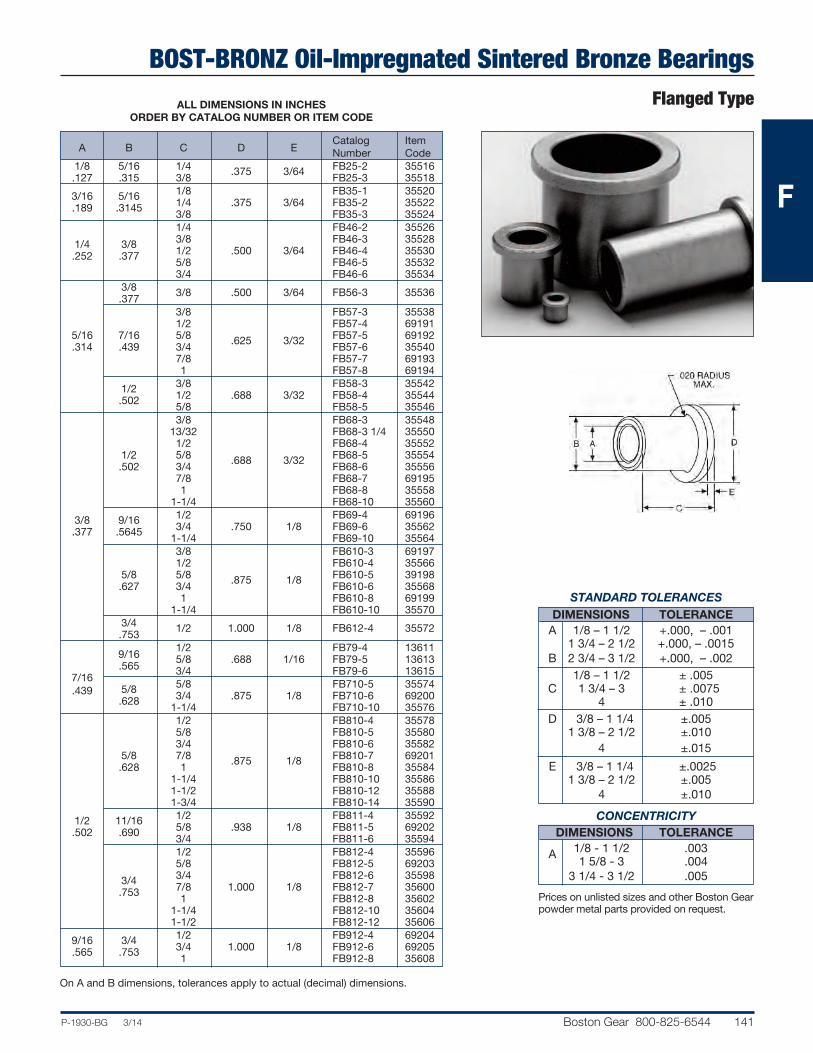
BOST-BRONZ Oil-Impregnated Sintered Bronze BearingsFlanged Type
P-1930-BG 3/14 Boston Gear 800-825-6544 141
Catalog Item A B C D E Number Code 1/8 5/16 1/4 .375 3/64 FB25-2 35516 .127 .315 3/8 FB25-3 35518 3/16 5/16 1/8 FB35-1 35520 .189 .3145 1/4 .375 3/64 FB35-2 35522 3/8 FB35-3 35524 1/4 FB46-2 35526 1/4 3/8 3/8 FB46-3 35528 .252 .377 1/2 .500 3/64 FB46-4 35530 5/8 FB46-5 35532 3/4 FB46-6 35534 3/8 3/8 .500 3/64 FB56-3 35536 .377 3/8 FB57-3 35538 1/2 FB57-4 69191 5/16 7/16 5/8 .625 3/32 FB57-5 69192 .314 .439 3/4 FB57-6 35540 7/8 FB57-7 69193 1 FB57-8 69194 1/2 3/8 FB58-3 35542 .502 1/2 .688 3/32 FB58-4 35544 5/8 FB58-5 35546 3/8 FB68-3 35548 13/32 FB68-3 1/4 35550 1/2 FB68-4 35552 1/2 5/8 .688 3/32 FB68-5 35554 .502 3/4 FB68-6 35556 7/8 FB68-7 69195 1 FB68-8 35558 1-1/4 FB68-10 35560 3/8 9/16 1/2 FB69-4 69196 .377 .5645 3/4 .750 1/8 FB69-6 35562 1-1/4 FB69-10 35564 3/8 FB610-3 69197 1/2 FB610-4 35566 5/8 5/8 .875 1/8 FB610-5 39198 .627 3/4 FB610-6 35568 1 FB610-8 69199 1-1/4 FB610-10 35570 3/4 1/2 1.000 1/8 FB612-4 35572 .753
9/16 1/2 FB79-4 13611
.565
5/8 .688 1/16 FB79-5 13613 7/16
3/4 FB79-6 13615 .439
5/8 5/8 FB710-5 35574 .628 3/4 .875 1/8 FB710-6 69200 1-1/4 FB710-10 35576 1/2 FB810-4 35578 5/8 FB810-5 35580 3/4 FB810-6 35582 5/8 7/8 .875 1/8 FB810-7 69201 .628 1 FB810-8 35584 1-1/4 FB810-10 35586 1-1/2 FB810-12 35588 1-3/4 FB810-14 35590 1/2 11/16 1/2 FB811-4 35592 .502 .690 5/8 .938 1/8 FB811-5 69202 3/4 FB811-6 35594 1/2 FB812-4 35596 5/8 FB812-5 69203 3/4 3/4 FB812-6 35598 .753 7/8 1.000 1/8 FB812-7 35600 1 FB812-8 35602 1-1/4 FB812-10 35604 1-1/2 FB812-12 35606 9/16 3/4 1/2 FB912-4 69204 .565 .753 3/4 1.000 1/8 FB912-6 69205 1 FB912-8 35608
ALL DIMENSIONS IN INCHESORDER BY CATALOG NUMBER OR ITEM CODE
On A and B dimensions, tolerances apply to actual (decimal) dimensions.
STANDARD TOLERANCESDIMENSIONS TOLERANCE
A 1/8 – 1 1/2 +.000, – .001 1 3/4 – 2 1/2 +.000, – .0015 B 2 3/4 – 3 1/2 +.000, – .002 1/8 – 1 1/2 ± .005 C 1 3/4 – 3 ± .0075 4 ± .010 D 3/8 – 1 1/4 ±.005 1 3/8 – 2 1/2 ±.010 4 ±.015
E 3/8 – 1 1/4 ±.0025 1 3/8 – 2 1/2 ±.005 4 ±.010
CONCENTRICITYDIMENSIONS TOLERANCE
A 1/8 - 1 1/2 .003 1 5/8 - 3 .004 3 1/4 - 3 1/2 .005
Prices on unlisted sizes and other Boston Gearpowder metal parts provided on request.
F

BOST-BRONZ Oil-Impregnated Sintered Bronze BearingsFlanged Type
142 Boston Gear 800-825-6544 P-1930-BG 3/14
Catalog Item A B C D E Number Code 1/2 FB1012-4 35610 5/8 3/4 5/8 FB1012-5 35612 .626 .753 3/4 1.000 1/8 FB1012-6 35614 1 FB1012-8 35616 1-1/4 FB1012-10 35618 5/8 FB1013-5 69206 3/4 FB1013-6 35620 13/16 1 FB1013-8 35622 .815 1-1/4 1.063 5/32 FB1013-10 35624 1-7/16 FB1013-111/2 35626 5/8 1-1/2 FB1013-12 35628 .627 2 FB1013-16 35630 5/8 FB1014-5 69207 7/8 3/4 1.125 5/32 FB1014-6 35632 .878 1 FB1014-8 35634 1-3/4 FB1014-14 35636 1 3/4 1.250 5/32 FB1016-6 69208 1.003 1 FB1016-8 35638 7/8 3/4 FB1214-6 35644 .878 1 1.125 5/32 FB1214-8 35646 1-1/4 FB1214-10 69209 15/16 1 FB1215-8 35648 3/4 .940 1-1/4 1.188 5/32 FB1215-10 69213 .752 1-1/2 FB1215-12 35650 5/8 FB1216-5 69214 3/4 FB1216-6 35652 1 1 1.250 5/32 FB1216-8 35654 1.003 1-1/4 FB1216-10 35656 1-1/2 FB1216-12 35658 2 FB1216-16 35660 1 3/4 FB1416-6 35662 1.003 1 1.250 5/32 FB1416-8 69210 7/8 1-1/4 FB1416-10 35664 .877 1 FB1418-8 35666 1-1/8 1-1/4 1.375 5/32 FB1418-10 69211 1.128 1-1/2 FB1418-12 35668 3/4 FB1620-6 35672 1-1/4 1 FB1620-8 35674 1.253 1-1/4 1.500 3/16 FB1620-10 35676 1 1-1/2 FB1620-12 35678 1.002 2 FB1620-16 35680 1-3/8 1 FB1622-8 35682 1.378 1-1/2 1.625 3/16 FB1622-12 69215 1-3/4 FB1622-14 35684 1-1/8 1-3/8
3/4 FB1822-6 13617 1.127 1.377
1 1.750 1/8 FB1822-8 13619 1-1/4 FB1822-10 13621 1-1/4 1-1/2 1 FB2024-8 69216 1.252 1.503 1-1/4 1.750 3/16 FB2024-10 35686 1-1/2 FB2024-12 69217 1-3/8 1-5/8 3/4
2,000 1/8 FB2226-6 13623
1.377 1.628 1 FB2226-8 13625 1-1/2 1-3/4 1-1/2 2.063 3/16 FB2428-12 35688 1.503 1.754
2
2-1/4 3/4 FB3236-6 13627
2.003
2.254
1 2.500 1/8 FB3236-8 13629 1-1/4 FB3236-10 13631 2-3/4 3-1/4
1-1/2 4.000 3/16 FB4452-12 13635 2.752 3.255
ALL DIMENSIONS IN INCHESORDER BY CATALOG NUMBER OR ITEM CODE
On A and B dimensions, tolerances apply to actual (decimal) dimensions.
STANDARD TOLERANCESDIMENSIONS TOLERANCE
A 1/8 – 1 1/2 +.000, – .001 1 3/4 – 2 1/2 +.000, – .0015 B 2 3/4 – 3 1/2 +.000, – .002 1/8 – 1 1/2 ± .005 C 1 3/4 – 3 ± .0075 4 ± .010 3/8 – 1 1/4 ± .005 D 1 3/8 – 2 1/2 ± .010 4 ± .015 3/8 – 1 1/4 ± .0025 E 1 3/8 – 2 1/2 ± .005 4 ± .010
CONCENTRICITY
DIMENSIONS TOLERANCE 1/8 – 1 1/2 .003 A 1 5/8 – 3 .004 3 1/4 – 3 1/2 .005
Prices on unlisted sizes and other Boston Gearpowder metal parts provided on request.
F

BOST-BRONZ Oil-Impregnated Sintered Bronze BearingsThrust Type
P-1930-BG 3/14 Boston Gear 800-825-6544 143
Catalog Item A B C Number Code 7/16
1/16 TB47 13515 .4375 1/4 1/2
1/16 TB48 13517 .255 .500 5/8 1/16 TB410 35766 .625 5/8
1/16 TB510 13519 5/16 .625 .315 3/4 1/16 TB512 35768 .750 3/8 5/8
1/16 TB610 13521 .385 .625 3/4 1/32 TB612 35770 3/8 .750 .380 3/4 1/8 TB612-2 13523 .750 7/16 3/4 1/16 TB712 69218 .440 .750 1/2 3/4 1/16 TB812 35772 .505 .750 1/2 7/8 3/16 TB814 35774 .505 .875 1/2 1 1/16 TB816 35776 .510 1.000 9/16 1-1/4 1/8 TB920 35778 .565 1.250 1 1/8 TB1016 35780 1.000 5/8 1-3/16 3/32 TB1019 35782 .628 1.187 1-1/4 1/8 TB1020 69219 1.250 5/8 1-1/2 1/8 TB1024 69220 .6265 1.500 1-1/4 1/8 TB1220 69221 3/4 1.250 .753 1-3/8 1/8 TB1222 69222 1.375
Plate StockBOST-BRONZ is stocked in thisconvenient Plate form for ease inmachining to required bearing size or shape — at your service for allemergencies.
ALL DIMENSIONS IN INCHESORDER BY CATALOG NUMBER OR ITEM CODE
Catalog Item A B C Number Code 1-9/16 3/32 TB1225 35784 3/4 1.562 .765 1-3/4 1/8 TB1228 35786 1.750 7/8 1-1/2 1/8 TB1424 35788 .8905 1.500 7/8 2
1/8 TB1432 13525 .880 2.000 7/8 2-1/8 1/8 TB1434 35790 .8905 2.125 1-1/2 1/8 TB1624 35792 1 1.504 1.003 1-1/2
3/16 TB1624-3 13527 1.500 1 1-5/8
1/4 TB1626-4 13529 1.0155 1.625 1 1-3/4
1/8 TB1628 13531 1.0120 1.750 1 2 1/8 TB1632 35794 1.016 2.000 1 2-7/8 1/8 TB1646 13533 1.0155 2.875 1-1/8 1-7/8
1/8 TB1830 13535 1.140 1.875 1-1/4 1-3/4 1/8 TB2028 35796 1.253 1.750 2
1/8 TB2032 13537 1-1/4 2.000 1.265 2-3/8
1/8 TB2038 13539 2.375 1-1/9 3-5/16
1/8 TB2053 13541 1.255 3.312 1-3/8 1-15/16
1/8 TB2231 13543 1.379 1.940 1-1/2 2
1/8 TB2432 13545 1.503 2.000 1-1/2 2-1/2
1/8 TB2440 13547 1.505 2.505 1-1/2 3-1/2 3/16 TB2456 35798 1.510 3.500 1-9/16 2-7/16
1/8 TB2539 13549 1.578 2.4375 1-3/4 2-5/8
1/8 TB2842 13551 1.765 2.625 2 3
1/4 TB3248 13553 2.011 3.000 2 3-5/8
3/16 TB3258 13555 2.031 2.625 2-1/16 4
1/8 TB3364 13557 2.062 4.000 2-1/2 3-1/4
1/8 TB4052 13559 2.502 3.250
On A and B dimensions, tolerances apply toactual (decimal) dimensions.
Catalog Item
A B C Number Code
1/8 PB5602 35692 3/16 5 6 PB5603 35694 1/4 PB5604 35696 5/16 PB5605 35698 3/8 PB5606 35700 1/2 PB5608 35702 5/8 5 6 PB5610 35704 3/4 PB5612 35706 1 PB5616 35708 3/16 5 8 PB5803 35710 1/4 PB5804 35712
STANDARD TOLERANCES
DIMENSIONS TOLERANCE 1/4 – 1 1/4 ±.010 A 1 3/8 –2 1/2 ±.015 7/16 – 1 1/2 ±.010 B 1 9/16 – 3 ±.015 3 1/4 – 4 ±.020 C All ± .0025
STANDARD TOLERANCESDIMENSIONS TOLERANCE
A All ±.010 to –.005
Keep BOST-BRONZ plate stock on hand for: Breakdowns – maintenance and repairs – Producing small lots of special sizes –Experimental and development work.
ALL DIMENSIONS IN INCHESORDER BY CATALOG NUMBER OR ITEM CODE
F

BOST-BRONZ Oil-Impregnated Sintered Bronze BearingsCored Bars
144 Boston Gear 800-825-6544 P-1930-BG 3/14
Solid Bars
ALL DIMENSIONS IN INCHESORDER BY CATALOG NUMBER OR ITEM CODE
Catalog Item A B Number Code 1 CB816 35402 1/2 1-1/4 CB820 35404 1-1/2 CB824 35406 1 CB1016 35408 1-1/4 CB1020 35410 5/8 1-3/8 CB1022 35412 1-1/2 CB1024 35414 1-3/4 CB1028 35416 1-1/4 CB1220 35418 1-1/2 CB1224 35420 3/4 1-3/4 CB1228 35422 2 CB1232 35424 2-1/2 CB1240 35426 7/8 1-3/8 CB1422 35428 1-1/2 CB1624 35430 1-3/4 CB1628 35432 1 2 CB1632 35434 2-1/4 CB1636 35436 2-1/2 CB1640 35438 3 CB1648 35440 1-3/4 CB2028 35442 2 CB2032 35444 1-1/4 2-1/4 CB2036 35446 2-1/2 CB2040 35448 3 CB2048 35450 1-3/8 2 CB2232 35452 2 CB2432 35456 2-1/4 CB2436 35458 1-1/2 2-1/2 CB2440 35460 3 CB2448 35462 3-1/2 CB2456 35464
Catalog Item A B Number Code 2-1/4 CB2836 35466 2-1/2 CB2840 35468 1-3/4 2-3/4 CB2844 35470 3 CB2848 35472 3-1/2 CB2856 35474 2-3/4 CB3244 35476 3 CB3248 35478 2 3-1/4 CB3252 35480 4 CB3264 35482 4-1/2 CB3272 35484 5 CB3280 35486 3 CB3648 35488 2-1/4 3-1/2 CB3656 35490 3-3/4 CB3660 35492 2-3/8 3 CB3848 35494 2-1/2 3-1/2 CB4056 35496 3-3/4 CB4860 35498 3 4 CB4864 35500 5 CB4880 35502 6 CB4896 35504 3-1/2 4-3/4 CB5676 35506 4 6 CB6496 35512 5 7 CB80112 35514
All bars are 6 1/2" long.
Catalog Item
B Length Number Code
1/4 2 SB4 35714 3/8 3 SB6 35716 1/2 SB8 35718 5/8 6-1/2 SB10 35720 3/4 SB12 35722 7/8 SB14 35724 1 SB16 35726 1-1/8 6-1/2 SB18 35728 1-1/4 SB20 35730 1-3/8 SB22 35732 1-1/2 SB24 35734 1-5/8 6-1/2 SB26 35736 1-3/4 SB28 35738 2 SB32 35742 2-1/4 6-1/2 SB36 35744 2-1/2 SB40 35746 3 SB48 35748 3-1/2 SB56 35750 4 6-1/2 SB64 35752 4-1/2 SB72 35754 5 SB80 35756 5-1/2 SB88 35758 6 6-1/2 SB96 35760 7 SB112 35762 8 SB128 35764
ALL DIMENSIONS IN INCHESORDER BY CATALOG NUMBER OR ITEM CODE
BOST-BRONZ is stocked in these convenient Bar forms for ease inmachining to required bearing size or shape — at your service for allemergencies.
STANDARD TOLERANCES
DIMENSIONS TOLERANCE A All –1/8” B All +1/8”
STANDARD TOLERANCES
DIMENSIONS TOLERANCE B All + 1/8”
F

BEAR-N-BRONZE 660 Cast Bronze Bearings
P-1930-BG 3/14 Boston Gear 800-825-6544 145
BEAR-N-BRONZ is Boston Gear’s general purpose cast, solidbronze bearing material. It is a high grade, leaded-tin bronze,having good hardness, strength, wear-resistance, and exceptional anti-friction qualities. It is particularly suited formoderate to heavy loads at normal to relatively high speeds.
QualityBEAR-N-BRONZ is chemically and metallurgically tested toassure conformance to specifications. All parts are rigidlyinspected to assure freedom from porosity and conformanceto dimensional tolerances.
AdaptabilityBEAR-N-BRONZ bearings are completely machined to closetolerances permitting wider housing-bore tol er ances. BEAR-N-BRONZ bars are machined all over.
Avg. Avg. Yield
Elonga- Brinnell Composition
Tensile Strength tion in Hardness
(%)
Strength 0.2% Two Inch (500 Kg
(Lbs. Per Offset (%) Load)
Sq. In.) (Lbs. Per Sq. In.)
Copper (Cu) 83 35,000 20,000 15 60
Tin (Sn) 7 Bear-N-Bronz conforms to SAE CA932 (660)Lead (Pb) 7 and ASTM B584-78 (alloy C93200)Zinc (Zn) 3 specifications.
Special CompositionsIn addition to our standard BEAR-N-BRONZ (SAE CA 932) material, many special compositions can be furnished on a made-to-order basis.
The Chemical compositions and physical properties of someof the more popular are listed.
206 Copper (Cu) 88 Leaded CA927 Tin (Sn) 1040,00020,000 25 70Gun Metal Lead (Pb) 2
210 Copper (Cu) 88Gun CA905 Tin (Sn) 10 45,000 22,000 25 65Metal Zinc (Zn) 2
305 Copper (Cu) 80Phosphor CA937 Tin (Sn) 10 35,000 18,000 20 63Bronze Lead (Pb) 10
319 Copper (Cu) 78Semi-Plastic CA938 Tin (Sn) 7 30,000 17,000 15 55Bronze Lead (Pb) 15
SelectionIn general, sleeve bearings should be selected with a length ofone to two times the shaft diameter and an O.D. approximately25% larger than the shaft diameter.
A general guide to determination of limiting load and velocityvalues for sleeve bearings has been estab lished by the use ofPV calculations. PV represents Pressure x Velocity, for example 100 psi x 20 fpm yields a PV of 2000.
Maximum PV value for BEAR-N-BRONZ bearings: 75,000.
For complete selection and application information, seeEngineering Section, Pages 174-182.
Grade
Equivalent
S.A.E. Num
ber
Composition
(%)
Average
Yield Strength
0.2%
Offset
(Lbs. Per Sq. In.)
Average
Tensile Strength
(Lbs. Per Sq. In.)
Elongation in
Two Inch (%
)
Brinnell
Hardness
(500 Kg Load)
F
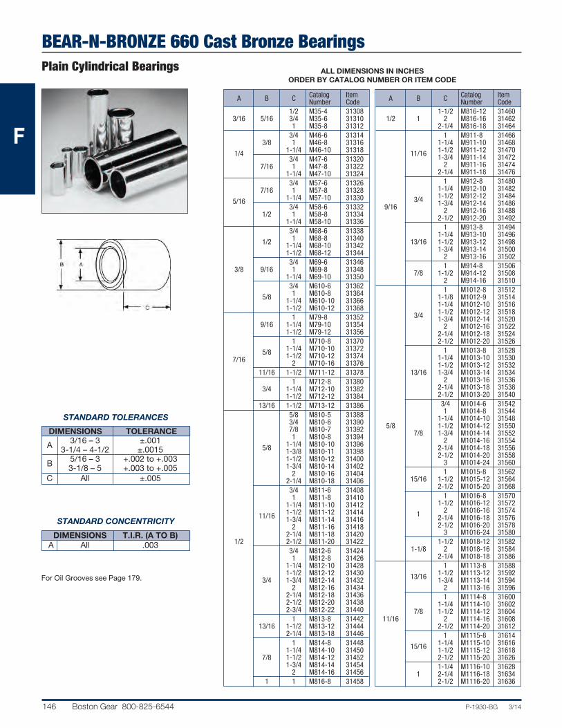
BEAR-N-BRONZE 660 Cast Bronze BearingsPlain Cylindrical Bearings
146 Boston Gear 800-825-6544 P-1930-BG 3/14
ALL DIMENSIONS IN INCHESORDER BY CATALOG NUMBER OR ITEM CODE
Catalog Item A B C Number Code 1/2 M35-4 31308 3/16 5/16 3/4 M35-6 31310 1 M35-8 31312 3/4 M46-6 31314 3/8 1 M46-8 31316 1/4 1-1/4 M46-10 31318 3/4 M47-6 31320 7/16 1 M47-8 31322 1-1/4 M47-10 31324 3/4 M57-6 31326 7/16 1 M57-8 31328 5/16 1-1/4 M57-10 31330 3/4 M58-6 31332 1/2 1 M58-8 31334 1-1/4 M58-10 31336 3/4 M68-6 31338 1/2 1 M68-8 31340 1-1/4 M68-10 31342 1-1/2 M68-12 31344 3/4 M69-6 31346 3/8 9/16 1 M69-8 31348 1-1/4 M69-10 31350 3/4 M610-6 31362 5/8 1 M610-8 31364 1-1/4 M610-10 31366 1-1/2 M610-12 31368 1 M79-8 31352 9/16 1-1/4 M79-10 31354 1-1/2 M79-12 31356 1 M710-8 31370 5/8 1-1/4 M710-10 31372 7/16 1-1/2 M710-12 31374 2 M710-16 31376 11/16 1-1/2 M711-12 31378 1 M712-8 31380 3/4 1-1/4 M712-10 31382 1-1/2 M712-12 31384 13/16 1-1/2 M713-12 31386 5/8 M810-5 31388 3/4 M810-6 31390 7/8 M810-7 31392 1 M810-8 31394 5/8 1-1/4 M810-10 31396 1-3/8 M810-11 31398 1-1/2 M810-12 31400 1-3/4 M810-14 31402 2 M810-16 31404 2-1/4 M810-18 31406 3/4 M811-6 31408 1 M811-8 31410 1-1/4 M811-10 31412 11/16 1-1/2 M811-12 31414 1-3/4 M811-14 31416 2 M811-16 31418 2-1/4 M811-18 31420 1/2 2-1/2 M811-20 31422 3/4 M812-6 31424 1 M812-8 31426 1-1/4 M812-10 31428 1-1/2 M812-12 31430 3/4 1-3/4 M812-14 31432 2 M812-16 31434 2-1/4 M812-18 31436 2-1/2 M812-20 31438 2-3/4 M812-22 31440 1 M813-8 31442 13/16 1-1/2 M813-12 31444 2-1/4 M813-18 31446 1 M814-8 31448 1-1/4 M814-10 31450 7/8 1-1/2 M814-12 31452 1-3/4 M814-14 31454 2 M814-16 31456 1 1 M816-8 31458
Catalog Item A B C Number Code 1-1/2 M816-12 31460 1/2 1 2 M816-16 31462 2-1/4 M816-18 31464 1 M911-8 31466 1-1/4 M911-10 31468 11/16 1-1/2 M911-12 31470 1-3/4 M911-14 31472 2 M911-16 31474 2-1/4 M911-18 31476 1 M912-8 31480 1-1/4 M912-10 31482 3/4 1-1/2 M912-12 31484 9/16 1-3/4 M912-14 31486 2 M912-16 31488 2-1/2 M912-20 31492 1 M913-8 31494 1-1/4 M913-10 31496 13/16 1-1/2 M913-12 31498 1-3/4 M913-14 31500 2 M913-16 31502 1 M914-8 31506 7/8 1-1/2 M914-12 31508 2 M914-16 31510 1 M1012-8 31512 1-1/8 M1012-9 31514 1-1/4 M1012-10 31516 3/4 1-1/2 M1012-12 31518 1-3/4 M1012-14 31520 2 M1012-16 31522 2-1/4 M1012-18 31524 2-1/2 M1012-20 31526 1 M1013-8 31528 1-1/4 M1013-10 31530 1-1/2 M1013-12 31532 13/16 1-3/4 M1013-14 31534 2 M1013-16 31536 2-1/4 M1013-18 31538 2-1/2 M1013-20 31540 3/4 M1014-6 31542 1 M1014-8 31544 1-1/4 M1014-10 31548 5/8 1-1/2 M1014-12 31550 7/8 1-3/4 M1014-14 31552 2 M1014-16 31554 2-1/4 M1014-18 31556 2-1/2 M1014-20 31558 3 M1014-24 31560 1 M1015-8 31562 15/16 1-1/2 M1015-12 31564 2-1/2 M1015-20 31568 1 M1016-8 31570 1-1/2 M1016-12 31572 1 2 M1016-16 31574 2-1/4 M1016-18 31576 2-1/2 M1016-20 31578 3 M1016-24 31580 1-1/2 M1018-12 31582 1-1/8 2 M1018-16 31584 2-1/4 M1018-18 31586 1 M1113-8 31588 13/16 1-1/2 M1113-12 31592 1-3/4 M1113-14 31594 2 M1113-16 31596 1 M1114-8 31600 1-1/4 M1114-10 31602 7/8 1-1/2 M1114-12 31604 11/16 2 M1114-16 31608 2-1/2 M1114-20 31612 1 M1115-8 31614 15/16 1-1/4 M1115-10 31616 1-1/2 M1115-12 31618 2-1/2 M1115-20 31626 1-1/4 M1116-10 31628 1 2-1/4 M1116-18 31634 2-1/2 M1116-20 31636
STANDARD TOLERANCES
DIMENSIONS TOLERANCE 3/16 – 3 ±.001 A 3-1/4 – 4-1/2 ±.0015 5/16 – 3 +.002 to +.003 B 3-1/8 – 5 +.003 to +.005 C All ±.005
STANDARD CONCENTRICITY
DIMENSIONS T.I.R. (A TO B) A All .003
For Oil Grooves see Page 179.
F

BEAR-N-BRONZE 660 Cast Bronze BearingsPlain Cylindrical Bearings
P-1930-BG 3/12 Boston Gear 800-825-6544 147
ALL DIMENSIONS IN INCHESORDER BY CATALOG NUMBER OR ITEM CODE
Catalog Item A B C Number Code 3/4 M1214-6 31640 1 M1214-8 31642 1-1/4 M1214-10 31644 7/8 1-1/2 M1214-12 31646 1-3/4 M1214-14 31648 2 M1214-16 31650 2-1/4 M1214-18 31652 2-1/2 M1214-20 31654 1 M1215-8 31656 1-1/4 M1215-10 31658 1-1/2 M1215-12 31662 15/16 1-3/4 M1215-14 31664 2 M1215-16 31666 2-1/4 M1215-18 31668 2-1/2 M1215-20 31670 3 M1215-24 31674 3/4 M1216-6 31676 1 M1216-8 31678 1-1/8 M1216-9 31680 1-1/4 M1216-10 31682 1-3/8 M1216-11 31684 1-1/2 M1216-12 31686 1 1-3/4 M1216-14 31688 3/4 2 M1216-16 31690 2-1/8 M1216-17 31692 2-1/4 M1216-18 31694 2-1/2 M1216-20 31696 2-3/4 M1216-22 31698 3 M1216-24 31700 3-1/2 M1216-28 31702 1 M1217-8 31704 1-1/16 1-1/2 M1217-12 31706 2 M1217-16 31708 3 M1217-24 31714 1 M1218-8 31716 1-1/2 M1218-12 31718 1-1/8 2 M1218-16 31720 2-1/2 M1218-20 31724 3 M1218-24 31726 1-3/16 1-1/2 M1219-12 31728 2 M1219-16 31730 1-3/4 M1220-14 31734 1-1/4 2 M1220-16 31736 2-1/2 M1220-20 31740 3 M1220-24 31742 1 M1315-8 31744 15/16 1-1/2 M1315-12 31748 2 M1315-16 31750 1-1/2 M1316-12 31752 1 2 M1316-16 31756 13/16 2-1/2 M1316-20 31758 1-1/2 M1317-12 31760 1-1/16 2 M1317-16 31762 2-3/4 M1317-22 31766 1-1/8 1-1/2 M1318-12 31770 2 M1318-16 31772 1 M1416-8 31788 1-1/4 M1416-10 31790 1 1-3/8 M1416-11 31792 1-1/2 M1416-12 31794 1-5/8 M1416-13 31796 2 M1416-16 31798 1 M1417-8 31800 1-1/4 M1417-10 31802 1-1/2 M1417-12 31804 7/8 1-1/16 1-3/4 M1417-14 31806 2 M1417-16 31808 2-1/4 M1417-18 31810 2-1/2 M1417-20 31812 3 M1417-24 31816 3/4 M1418-6 31818 1-1/8 1 M1418-8 31820 1-1/4 M1418-10 31822 1-3/8 M1418-11 31824
Catalog Item A B C Number Code 1-1/2 M1418-12 31826 1-3/4 M1418-14 31828 2 M1418-16 31830 1-1/8 2-1/4 M1418-18 31832 2-1/2 M1418-20 31834 3 M1418-24 31836 3-1/4 M1418-26 31838 3-1/2 M1418-28 31840 7/8 1-3/16 1 M1419-8 31842 3 M1419-24 31852 1-1/2 M1420-12 31854 1-3/4 M1420-14 31856 2 M1420-16 31858 1-1/4 2-1/4 M1420-18 31860 2-1/2 M1420-20 31862 3 M1420-24 31864 3-1/2 M1420-28 31866 1-1/2 M1422-12 31868 1-3/8 2 M1422-16 31872 2-1/2 M1422-20 31874 3 M1422-24 31876 1-1/8 1-1/2 M1518-12 31878 2 M1518-16 31880 1-1/4 M1519-10 31884 1-3/16 1-1/2 M1519-12 31886 2 M1519-16 31888 15/16 3 M1519-24 31894 1 M1520-8 31896 1-1/2 M1520-12 31898 1-1/4 2 M1520-16 31900 2-1/2 M1520-20 31902 2-3/4 M1520-22 31904 1-5/16 1-1/2 M1521-12 31906 2 M1521-16 31910 1-3/8 M1618-11 31916 1-1/2 M1618-12 31918 1-1/8 1-3/4 M1618-14 31920 2 M1618-16 31922 2-1/2 M1618-20 31924 7/8 M1619-7 31926 1-1/4 M1619-10 31928 1-3/16 1-1/2 M1619-12 31930 1-3/4 M1619-14 31932 2 M1619-16 31934 2-1/2 M1619-20 31936 3/4 M1620-6 31938 1 M1620-8 31940 1-1/8 M1620-9 31942 1-1/4 M1620-10 31944 1-3/8 M1620-11 31946 1-1/2 M1620-12 31948 1-5/8 M1620-13 31950 1 1-1/4 1-3/4 M1620-14 31952 2 M1620-16 31954 2-1/4 M1620-18 31956 2-1/2 M1620-20 31958 2-3/4 M1620-22 31960 3 M1620-24 31962 4 M1620-32 31968 4-1/2 M1620-36 31970 1-1/2 M1621-12 31972 2 M1621-16 31974 1-5/16 2-1/4 M1621-18 31976 2-1/2 M1621-20 31978 3 M1621-24 31980 3-1/2 M1621-28 31982 1-1/4 M1622-10 31988 1-3/8 1-1/2 M1622-12 31990 1-3/4 M1622-14 31992 2 M1622-16 31994
STANDARD TOLERANCES
DIMENSIONS TOLERANCE 3/16 – 3 ±.001 A 3-1/4 – 4-1/2 ±.0015 5/16 – 3 +.002 to +.003 B 3-1/8 – 5 +.003 to +.005 C All ±.005
STANDARD CONCENTRICITY
DIMENSIONS T.I.R. (A TO B) A All .003
For Oil Grooves see Page 179.
F

BEAR-N-BRONZE 660 Cast Bronze BearingsPlain Cylindrical Bearings
148 Boston Gear 800-825-6544 P-1930-BG 3/14
ALL DIMENSIONS IN INCHESORDER BY CATALOG NUMBER OR ITEM CODE
Catalog Item A B C Number Code 2-1/2 M1622-20 31996 2-3/4 M1622-22 31998 1-3/8 3 M1622-24 32000 3-1/2 M1622-28 32004 4 M1622-32 32006 4-1/2 M1622-36 32008 1-1/2 M1624-12 32010 1-3/4 M1624-14 32012 1-1/2 2 M1624-16 32014 1 2-1/2 M1624-20 32016 3 M1624-24 32018 4 M1624-32 32020 2 M1626-16 32022 1-5/8 2-1/2 M1626-20 32024 3 M1626-24 32026 3-1/2 M1626-28 32028 1-3/4 6-1/2 M1628-52 32030 2 3 M1632-24 32032 6-1/2 M1632-52 32034 1-1/2 M1721-12 32036 1-5/16 2 M1721-16 32038 1-1/16 2-1/2 M1721-20 32040 1-7/16 2-1/2 M1723-20 32050 1-1/2 M1820-12 32062 1-1/4 1-3/4 M1820-14 32064 2 M1820-16 32066 1-5/16 2-1/4 M1821-18 32068 2-1/2 M1821-20 32070 1 M1822-8 32072 1-1/4 M1822-10 32074 1-1/2 M1822-12 32076 1-3/4 M1822-14 32078 2 M1822-16 32080 1-3/8 2-1/4 M1822-18 32082 2-1/2 M1822-20 32084 3 M1822-24 32086 3-1/4 M1822-26 32088 3-1/2 M1822-28 32090 1-1/8 4 M1822-32 32092 1-7/16 1-1/2 M1823-12 32094 3 M1823-24 32098 1-1/2 M1824-12 32102 2 M1824-16 32104 1-1/2 2-1/2 M1824-20 32106 3 M1824-24 32108 3-1/2 M1824-28 32110 4 M1824-32 32112 1-3/4 M1826-14 32114 2 M1826-16 32116 1-5/8 2-1/2 M1826-20 32118 3 M1826-24 32120 3-1/2 M1826-28 32122 4-1/2 M1826-36 32126 1-7/8 6-1/2 M1830-52 32128 2 3 M1832-24 32130 1-3/4 M1922-14 32134 1-3/8 2 M1922-16 32136 2-1/2 M1922-20 32138 1-1/4 M1923-10 32140 1-1/2 M1923-12 32142 1-7/16 2 M1923-16 32144 2-1/2 M1923-20 32146 1-3/16 3 M1923-24 32148 3-1/2 M1923-28 32150 2 M1924-16 32152 1-1/2 3 M1924-24 32154 4 M1924-32 32158 1-9/16 3 M1925-24 32162 3-1/2 M1925-28 32164 2 M1926-16 32166 1-5/8 2-1/2 M1926-20 32168 3 M1926-24 32170
Catalog Item A B C Number Code 2 M1927-16 32172 1-3/16 1-11/16 2-1/2 M1927-20 32174 3 M1927-24 32176 1-7/16 2-1/2 M2023-20 32180 3 M2023-24 32182 1 M2024-8 32184 1-1/8 M2024-9 32186 1-1/4 M2024-10 32188 1-3/8 M2024-11 32190 1-1/2 M2024-12 32192 1-5/8 M2024-13 32194 1-3/4 M2024-14 32196 2 M2024-16 32198 2-1/4 M2024-18 32200 1-1/2 2-1/2 M2024-20 32202 2-3/4 M2024-22 32204 3 M2024-24 32206 3-1/4 M2024-26 32208 3-1/2 M2024-28 32210 4 M2024-32 32212 4-1/4 M2024-34 32214 4-1/2 M2024-36 32216 5 M2024-40 32218 5-1/2 M2024-44 32220 2 M2025-16 32222 2-1/2 M2025-20 32224 1-9/16 3 M2025-24 32226 1-1/4 3-1/2 M2025-28 32228 3-3/4 M2025-30 32230 1-3/4 M2026-14 32232 2 M2026-16 32234 2-1/2 M2026-20 32236 3 M2026-24 32238 1-5/8 3-1/4 M2026-26 32240 3-1/2 M2026-28 32242 4 M2026-32 32244 4-1/2 M2026-36 32246 4-3/4 M2026-38 32248 1-11/16 2 M2027-16 32250 3-1/4 M2027-26 32254 1-3/4 M2028-14 32258 2 M2028-16 32260 2-1/4 M2028-18 32262 2-1/2 M2028-20 32264 1-3/4 2-3/4 M2028-22 32266 3 M2028-24 32268 3-1/2 M2028-28 32270 3-3/4 M2028-30 32272 4 M2028-32 32274 5 M2028-40 32276 2 M2030-16 32278 1-7/8 2-1/2 M2030-20 32280 4 M2030-32 32284 3 M2032-24 32286 2 4 M2032-32 32288 6-1/2 M2032-52 32290 1-1/2 1-3/4 M2124-14 32296 3 M2124-24 32298 2 M2126-16 32306 1-5/16 1-5/8 3 M2126-24 32310 4-3/4 M2126-38 32314 1-13/16 3 M2129-24 32324 4 M2129-32 32328 1-7/8 3-1/2 M2130-28 32330 1-3/4 M2224-14 32334 1-1/2 2 M2224-16 32336 2-1/2 M2224-20 32338 2 M2226-16 32340 1-3/8 3 M2226-24 32342 1-5/8 3-1/4 M2226-26 32344 3-1/2 M2226-28 32346 4 M2226-32 32348 1-11/16 3-1/2 M2227-28 32352
STANDARD TOLERANCES
DIMENSIONS TOLERANCE 3/16 – 3 ±.001 A 3-1/4 – 4-1/2 ±.0015 5/16 – 3 +.002 to +.003 B 3-1/8 – 5 +.003 to +.005 C All ±.005
STANDARD CONCENTRICITY
DIMENSIONS T.I.R. (A TO B) A All .003
For Oil Grooves see Page 179.
F

BEAR-N-BRONZE 660 Cast Bronze BearingsPlain Cylindrical Bearings
P-1930-BG 3/14 Boston Gear 800-825-6544 149
ALL DIMENSIONS IN INCHESORDER BY CATALOG NUMBER OR ITEM CODE
Catalog Item A B C Number Code 2 M2228-16 32354 2-1/4 M2228-18 32356 1-3/4 2-1/2 M2228-20 32358 3 M2228-24 32360 3-1/2 M2228-28 32362 1-3/8 4 M2228-32 32364 3 M2230-24 32366 1-7/8 3-1/2 M2230-28 32368 4 M2230-32 32370 4-1/2 M2230-36 32372 2 3 M2232-24 32374 4 M2232-32 32376 2-1/8 6-1/2 M2234-52 32378 1-3/4 M2326-14 32380 1-5/8 2-3/4 M2326-22 32382 3 M2326-24 32384 2-1/2 M2327-20 32386 1-11/16 3 M2327-24 32388 3-1/2 M2327-28 32390 4 M2327-32 32392 2-1/4 M2328-18 32396 1-7/16 1-3/4 3 M2328-24 32398 4 M2328-32 32400 1-13/16 3 M2329-24 32402 4-1/4 M2329-34 32410 3 M2330-24 32414 1-7/8 4 M2330-32 32416 4-1/2 M2330-36 32420 5 M2330-40 32422 1-15/16 2 M2331-16 32424 3 M2331-24 32426 2 4 M2332-32 32438 1-5/8 2 M2426-16 32440 1-11/16 2-3/4 M2427-22 32442 1-3/4 M2428-14 32444 2 M2428-16 32446 2-1/4 M2428-18 32448 2-1/2 M2428-20 32450 1-3/4 3 M2428-24 32452 3-1/2 M2428-28 32454 4 M2428-32 32456 4-1/2 M2428-36 32458 5 M2428-40 32460 5-1/2 M2428-44 32462 1-13/16 3 M2429-24 32464 2 M2430-16 32466 2-1/2 M2430-20 32468 2-3/4 M2430-22 32470 3 M2430-24 32472 1-7/8 3-1/2 M2430-28 32474 1-1/2 4 M2430-32 32476 4-1/2 M2430-36 32478 5 M2430-40 32480 5-1/2 M2430-44 32482 2-1/2 M2432-20 32484 3 M2432-24 32486 2 3-1/2 M2432-28 32488 4 M2432-32 32490 4-1/2 M2432-36 32492 5 M2432-40 32494 2-1/8 3 M2434-24 32496 4 M2434-32 32498 3 M2436-24 32500 2-1/4 4 M2436-32 32502 5 M2436-40 32504 6-1/2 M2436-52 32506 1-13/16 3 M2529-24 32508 1-9/16 3-1/2 M2529-28 32510 1-15/16 3-1/2 M2531-28 32514 2-1/4 M2630-18 32518 1-5/8 1-7/8 3 M2630-24 32520 3-3/4 M2630-30 32522
Catalog Item A B C Number Code 1-3/4 M2632-14 32526 2-1/2 M2632-20 32528 2 2 M2632-24 32530 1-5/8 4 M2632-32 32534 5 M2632-40 32538 5-1/2 M2632-44 32540 2-1/8 3 M2634-24 32542 4 M2634-32 32544 1-15/16 3 M2731-24 32550 3-1/2 M2731-28 32552 2 3-1/2 M2732-28 32554 4-1/2 M2732-36 32556 3 M2733-24 32558 2-1/16 4 M2733-32 32562 1-11/16 4-1/2 M2733-36 32564 5-1/2 M2733-44 32568 2 M2735-16 32570 2-3/16 3 M2735-24 32574 4 M2735-32 32578 2-1/4 3 M2736-24 32586 4-1/2 M2736-36 32588 2-1/4 M2832-18 32590 2-1/2 M2832-20 32592 2 3 M2832-24 32594 4 M2832-32 32596 4-1/2 M2832-36 32598 5-1/4 M2832-42 32600 2-1/16 3-1/2 M2833-28 32602 2-3/4 M2834-22 32604 3-1/4 M2834-26 32606 2-1/8 3-1/2 M2834-28 32608 4 M2834-32 32610 1-3/4 4-1/4 M2834-34 32612 5 M2834-40 32614 1-3/4 M2836-14 32618 2 M2836-16 32620 2-1/2 M2836-20 32622 2-1/4 3 M2836-24 32624 3-1/2 M2836-28 32626 4 M2836-32 32628 4-1/4 M2836-34 32630 5 M2836-40 32632 2-3/8 3-1/2 M2838-28 32634 5 M2838-40 32638 2-1/2 6-1/2 M2840-52 32640 2-3/16 4 M2935-32 32642 1-13/16 2-5/16 4 M2937-32 32646 5 M2937-40 32648 2-1/2 M3034-20 32650 2-1/8 3 M3034-24 32652 4 M3034-32 32654 1-7/8 2-1/4 3 M3036-24 32656 5 M3036-40 32662 3 M3038-24 32664 2-3/8 4 M3038-32 32666 5-1/4 M3038-42 32668 2-3/16 2 M3135-16 32670 3 M3135-24 32672 2-1/4 3 M3136-24 32676 4-1/2 M3136-36 32678 3-1/2 M3137-28 32680 2-5/16 4 M3137-32 32682 1-15/16 5 M3137-40 32684 6-1/4 M3137-50 32688 2-3/8 4 M3138-32 32692 5-1/2 M3138-44 32694 2-7/16 3 M3139-24 32696 2-1/2 3 M3140-24 32704 5 M3140-40 32706
STANDARD TOLERANCES
DIMENSIONS TOLERANCE 3/16 – 3 ±.001 A 3-1/4 – 4-1/2 ±.0015 5/16 – 3 +.002 to +.003 B 3-1/8 – 5 +.003 to +.005 C All ±.005
STANDARD CONCENTRICITY
DIMENSIONS T.I.R. (A TO B) A All .003
For Oil Grooves see Page 179.
F

BEAR-N-BRONZE 660 Cast Bronze BearingsPlain Cylindrical Bearings
150 Boston Gear 800-825-6544 P-1930-BG 3/14
ALL DIMENSIONS IN INCHESORDER BY CATALOG NUMBER OR ITEM CODE
Catalog Item A B C Number Code 2 M3236-16 32708 2-1/2 M3236-20 32710 2-1/4 3 M3236-24 32712 3-1/2 M3236-28 32714 4 M3236-32 32718 4-1/2 M3236-36 32720 3 M3238-24 32724 2-3/8 3-1/2 M3238-28 32726 4 M3238-32 32728 2 4-1/2 M3238-36 32730 2-1/2 M3240-20 32732 3 M3240-24 32734 3-1/2 M3240-28 32736 2-1/2 4 M3240-32 32738 4-1/2 M3240-36 32740 5 M3240-40 32742 6 M3240-48 32746 2-5/8 4 M3242-32 32748 2-3/4 6-1/2 M3244-52 32750 2-1/2 3 M3440-24 32752 4 M3440-32 32754 2-1/8 4 M3442-32 32756 2-5/8 5 M3442-40 32758 6 M3442-48 32760 2-5/8 4 M3542-32 32762 5 M3542-40 32764 3-1/2 M3543-28 32766 2-11/16 4-1/2 M3543-36 32770 2-3/16 5 M3543-40 32772 4-1/2 M3544-36 32774 2-3/4 5-1/4 M3544-42 32776 6 M3544-48 32778 2-7/8 4-1/2 M3546-36 32780 2-1/2 3-1/2 M3640-28 32782 4 M3640-32 32784 3 M3642-24 32786 2-5/8 4 M3642-32 32788 5 M3642-40 32790 2-11/16 4-3/4 M3643-38 32792 2-1/4 3-1/2 M3644-28 32794 4 M3644-32 32796 2-3/4 4-1/2 M3644-36 32798 5 M3644-40 32800 6 M3644-48 32802 3 3-1/2 M3648-28 32806 5 M3648-40 32808 2-3/4 4 M3844-32 32812 2-3/8 6 M3844-48 32816 2-7/8 4 M3846-32 32818 5 M3846-40 32820 2-3/4 4 M3944-32 32824 5 M3944-40 32826 2-7/8 3 M3946-24 32828 5 M3946-40 32830 2-7/16 4 M3947-32 32832 2-15/16 5 M3947-40 32834 6-1/4 M3947-50 32836 3-3/4 M3948-30 32838 3 5 M3948-40 32840 6-/14 M3948-50 32842 2-3/4 4 M4044-32 32844 5 M4044-40 32846 2-7/8 3-1/4 M4046-26 32848 2-1/2 4-1/2 M4046-36 32850 4 M4048-32 32852 3 5 M4048-40 32854 6 M4048-48 32856 7 M4048-56 32858
Catalog Item A B C Number Code 3-1/2 M4050-28 32860 3-1/8 4 M4050-32 32862 4-1/2 M4050-36 32864 2-1/2 4 M4052-32 32868 3-1/4 5 M4052-40 32870 6 M4052-48 32872 7-1/4 M4052-58 32874 3-1/2 6-1/2 M4056-52 32876 3 3 M4248-24 32878 5 M4248-40 32882 2-5/8 5 M4250-40 32884 3-1/8 6 M4250-48 32886 7-1/4 M4250-58 32888 3-1/4 7 M4252-56 32890 3-3/8 6-1/2 M4254-52 32892 2-11/16 3-3/16 6-1/4 M4351-50 32898 4 M4450-32 32900 3-1/8 5 M4450-40 32902 2-3/4 6 M4450-48 32904 4 M4452-32 32906 3-1/4 5 M4452-40 32908 6 M4452-48 32910 2-7/8 3-1/2 4-1/2 M4656-36 32926 6-3/4 M4656-54 32928 3-1/2 M4755-28 32930 2-15/16 3-7/16 5 M4755-40 32932 6-1/2 M4755-52 32934 3-3/8 4-1/2 M4854-36 32936 8 M4854-64 32938 4-1/2 M4856-36 32940 3 3-1/2 6 M4856-48 32942 9 M4856-72 32944 3-5/8 5 M4858-40 32946 3-3/4 6-1/4 M4860-50 32952 4 6-1/2 M4864-52 32954 3-1/4 3-1/2 4 M5256-32 32956 3-3/4 5 M5260-40 32958 3-7/16 3-15/16 4-1/2 M5563-36 32964 6-1/2 M5563-52 32966 4 5-1/2 M5664-44 32968 7 M5664-56 32970 3-1/2 4-1/8 6 M5666-48 32972 4-1/2 M5668-36 32974 4-1/4 7 M5668-56 32976 9-3/4 M5668-78 32978 4-1/4 5 M6068-40 32980 3-3/4 7 M6068-56 32982 4-1/2 6-1/2 M6072-52 32984 4 M6472-32 32986 4-1/2 6 M6472-48 32988 4 7 M6472-56 32990 5 5 M6480-40 32992 6 M6480-48 32994 5 M6876-40 32998 4-3/4 6 M6876-48 33000 4-1/4 7 M6876-56 33002 5 M6880-40 33004 5 6 M6880-48 33006 7 M6880-56 33008 6 M7280-48 33010 4-1/2 5 7 M7280-56 33012 8 M7280-64 33014
STANDARD TOLERANCES
DIMENSIONS TOLERANCE 3/16 – 3 ±.001 A 3-1/4 – 4-1/2 ±.0015 5/16 – 3 +.002 to +.003 B 3-1/8 – 5 +.003 to +.005 C All ±.005
STANDARD CONCENTRICITY
DIMENSIONS T.I.R. (A TO B) A All .003
For Oil Grooves see Page 179.
F

BEAR-N-BRONZE 660 Cast Bronze BearingsCored Bars
P-1930-BG 3/14 Boston Gear 800-825-6544 151
ALL DIMENSIONS IN INCHESORDER BY CATALOG NUMBER OR ITEM CODE
Aprx. A B Wgt. Catalog Item
(Lbs.) Number Code
1 2-3/4 MCB816 33016 1-1/8 3-3/4 MCB818 33018 1/2 1-1/4 4-3/4 MCB820 33020 1-1/2 7 MCB824 33024 1-3/4 9-3/4 MCB828 33026 2 12-3/4 MCB832 33028
1 2 MCB1016 47640 1-1/8 3 MCB1018 33030 1-1/4 4 MCB1020 33032 1-3/8 5 MCB1022 33034 5/8 1-1/2 6-1/2 MCB1024 33036 1-3/4 9 MCB1028 33040 1 1-1/2 MCB1216 47641 1-1/8 2-1/2 MCB1218 47642 1-1/4 3-1/2 MCB1220 33046 1-3/8 4-1/2 MCB1222 33048 1-1/2 5-1/2 MCB1224 33050 3/4 1-3/4 8 MCB1228 33054 2 11-1/2 MCB1232 33058 2-1/4 15 MCB1236 33062 2-1/2 19-1/2 MCB1240 33064 2-3/4 24 MCB1244 33066
1-1/8 1-7/8 MCB1418 47643 1-1/4 2-7/8 MCB1420 47644 1-3/8 4 MCB1422 33068 7/8 1-1/2 5 MCB1424 33070 1-5/8 6-1/2 MCB1426 33072 1-3/4 7-1/2 MCB1428 33074 2 11 MCB1432 33078
1-1/4 2 MCB1620 47645 1-3/8 3-1/8 MCB1622 47646 1-1/2 4-1/2 MCB1624 33084 1-5/8 5-1/2 MCB1626 33086 1-3/4 7 MCB1628 33088 1-7/8 8-1/2 MCB1630 33090 2 10 MCB1632 33092 1 2-1/4 13-1/2 MCB1636 33096 2-1/2 17-1/2 MCB1640 33100 2-3/4 22 MCB1644 33102 3 27 MCB1648 33104 2-1/4 32 MCB1652 33106 3-1/2 37-1/2 MCB1656 33108 4 50 MCB1664 33110
Aprx. A B Wgt. Catalog Item
(Lbs.) Number Code
1-3/8 2-1/4 MCB1822 47647 1-1/2 4-1/2 MCB1824 47648 1-5/8 5 MCB1826 33112 1-1/8 2-1/8 11-1/2 MCB1834 33120 2-3/8 15 MCB1838 33124 2-1/2 16-1/2 MCB1840 33126 2-3/4 21 MCB1844 33128 2-7/8 24 MCB1846 33130
1-1/2 2-1/2 MCB2024 47649 1-5/8 3-7/8 MCB2026 47650 1-3/4 5-1/2 MCB2028 33132 1-7/8 7 MCB2030 33134 2 8-1/2 MCB2032 33136 2-1/8 10-1/2 MCB2034 33138 2-1/4 12 MCB2036 33140 1-1/4 2-3/8 14 MCB2038 33142 2-1/2 16 MCB2040 33144 2-3/4 20 MCB2044 33148 3 25 MCB2048 33152 3-1/4 30 MCB2052 33154 3-1/2 35-1/2 MCB2056 33156
1-3/4 4-1/4 MCB2228 47652 1-7/8 6 MCB2230 33160 2 7-1/2 MCB2232 33162 2-1/8 9-1/2 MCB2234 33164 1-3/8 2-1/4 11 MCB2236 33166 2-3/8 12-1/2 MCB2238 33168
1-3/4 3 MCB2428 47653 1-7/8 4-1/2 MCB2430 47654 2 6 MCB2432 33178 2-1/8 8 MCB2434 33180 2-1/4 10 MCB2436 33182 2-3/8 11-1/2 MCB2438 33184 1-1/2 2-1/2 14 MCB2440 33186 2-3/4 18 MCB2444 33190 3-1/4 27-1/2 MCB2452 33194 3-1/2 33 MCB2456 33196 3-3/4 40 MCB2460 33198 4 45 MCB2464 33200 4-1/2 62 MCB2472 33202
All bars are 13" long.Contact factory for bars longer than 13". Available in lengths up to 105".
STANDARD TOLERANCES
DIMENSIONS TOLERANCE 1/2 – 4 – 1/16 A 4-1/4 – 8 – 1/8 1 – 4 + 1/16 B 4-1/4 – 9 + 1/8
F

BEAR-N-BRONZE 660 Cast Bronze BearingsCored Bars
152 Boston Gear 800-825-6544 P-1930-BG 3/14
ALL DIMENSIONS IN INCHESORDER BY CATALOG NUMBER OR ITEM CODE
Aprx. A B Wgt. Catalog Item
(Lbs.) Number Code
2 4-7/8 MCB2632 47655 1-5/8 2-1/8 7 MCB2634 33204 2-1/4 9 MCB2636 33206 2-3/8 10-1/2 MCB2638 33208
2 3-3/8 MCB2832 47656 2-1/8 5-1/8 MCB2834 47657 2-1/4 7-1/2 MCB2836 33218 2-3/8 9 MCB2838 33220 2-1/2 11 MCB2840 33222 2-5/8 13-1/2 MCB2842 33224 1-3/4 2-3/4 15-1/2 MCB2844 33226 3 20 MCB2848 33230 3-1/4 25 MCB2852 33232 3-1/2 31 MCB2856 33234 4 42-1/2 MCB2864 33238 4-1/4 50 MCB2868 33240
2-1/4 5-1/2 MCB3036 47658 2-3/8 7-1/2 MCB3038 33242 1-7/8 2-1/2 9-3/4 MCB3040 33244 2-5/8 12 MCB3042 33246 3-1/4 23 MBC3052 33254
2-1/4 3-7/8 MCB3236 47659 2-1/2 8-1/2 MCB3240 33256 2-5/8 10 MCB3242 33258 2-3/4 12-1/4 MCB3244 33260 3 16-1/2 MCB3248 33264 2 3-1/4 22 MBC3252 33266 3-1/2 29 MCB3256 33268 3-3/4 34 MCB3260 33270 4 39-1/2 MCB3264 33272 4-1/2 54 MCB3272 33274 5 69 MCB3280 33276 6 105-1/2 MCB3296 33278 2-1/8 2-5/8 8-1/2 MCB3442 33280 2-7/8 13 MCB3446 33284 2-3/4 9 MCB3644 33294 2-1/4 3-1/4 19 MBC3652 33302 3-1/2 25 MCB3656 33304 3-3/4 30-1/2 MCB3660 33306 4 37 MCB3664 33308 4-1/4 43 MCB3668 33310
Aprx. A B Wgt. Catalog Item
(Lbs.) Number Code
3 12 MCB3848 33314 2-3/8 4 35 MCB3864 33322
3 9-7/8 MCB4048 47661 3-1/8 13 MCB4050 33324 3-1/4 15 MCB4052 33326 3-1/2 21 MCB4056 33328 3-3/4 27 MCB4060 33330 4 33-1/2 MCB4064 33332 2-1/2 4-1/4 40 MCB4068 33334 4-1/2 46 MCB4072 33336 5 61 MCB4080 33340 5-1/2 78 MCB4088 33342
3-1/2 19-1/2 MCB4456 47662 3-3/4 22-1/2 MCB4460 33354 2-3/4 4 28-1/2 MCB4464 33356 4-1/4 35 MCB4468 33358 4-1/2 42 MCB4472 33360
2-7/8 4 26-3/4 MCB4664 33364
3-1/2 11-1/2 MCB4856 47663 3-3/4 18-1/4 MCB4860 33366 4 24-1/2 MCB4864 33368 4-1/4 31 MCB4868 33370 3 4-1/2 38 MCB4872 33372 4-3/4 45 MCB4876 33374 5 52 MCB4880 33376 5-1/2 70 MCB4888 33378 6 89-1/2 MCB4896 33380 6-1/2 110 MCB48104 33382
4 19-1/2 MCB5264 47664 4-1/4 25-1/2 MCB5268 33384 3-1/4 4-1/2 34 MCB5272 33386 4-3/4 41 MCB5276 33388 5 48 MCB5280 33390
4-1/4 20-7/8 MCB5668 47665 4-1/2 30 MCB5672 33394 4-3/4 35-1/2 MCB5676 33396 3-1/2 5 44 MCB5680 33398 5-1/2 61 MCB5688 33400 6 79 MCB5696 33402 6-1/2 107-1/2 MCB56104 47666
4-1/2 22-1/4 MCB6072 47667 4-3/4 29 MCB6076 33404 3-3/4 5 38 MCB6080 33406 6 74 MCB6096 33410
All bars are 13" long.Contact factory for bars longer than 13".
STANDARD TOLERANCES
DIMENSIONS TOLERANCE 1/2 – 4 – 1/16 A 4-1/4 – 8 – 1/8 1 – 4 + 1/16 B 4-1/4 – 9 + 1/8
F

BEAR-N-BRONZE 660 Cast Bronze BearingsCored Bars
P-1930-BG 3/14 Boston Gear 800-825-6544 153
ALL DIMENSIONS IN INCHESORDER BY CATALOG NUMBER OR ITEM CODE
ALL DIMENSIONS IN INCHESORDER BY CATALOG NUMBER OR ITEM CODE
Solid Bars
Aprx. A B Wgt. Catalog Item
(Lb.) Number Code
4-3/4 22-3/4 MCB6476 47668 5 32-1/4 MCB6480 47669 5-1/2 49 MCB6488 33412 4 6 67-1/2 MCB6496 33414 6-1/2 87 MCB64104 33416 7 109 MCB64112 33510 7-1/2 134 MCB64120 33512 5-1/2 41-1/4 MCB6888 47670 4-1/4 6 61 MCB6896 33418 6-1/2 82 MCB68104 33514 5-1/2 36 MCB7288 47671 4-1/2 6 56-1/2 MCB7296 47672 6-1/2 75 MCB72104 33420 7 97 MCB72112 33422 4-3/4 6 67 MCB7696 47673 6 39 MCB8096 33428 5 7 81 MCB80112 33430 7-1/2 104 MCB80120 33516 8 130 MCB80128 33518
Aprx. A B Wgt. Catalog Item
(Lb.) Number Code
5-1/4 7 77 MCB84112 47675 7-1/2 97 MCB84120 33432 6-1/2 43 MCB88104 47676 5-1/2 7 67-1/4 MCB88112 47677 7-1/2 91 MCB88120 33434 8 113 MCB88128 33436 5-3/4 7-1/2 79 MCB92120 33438 7 46-1/2 MCB96112 47678 7-1/2 72-1/2 MCB96120 47679 6 8 94 MCB96128 33440 9 151 MCB96144 33522 7-1/2 50-1/4 MCB104120 47681 6-1/2 8 84 MCB104128 47682 9 130 MCB104144 33442 8 9 61 MCB128144 47684
All bars are 13" long.Contact factory for bars longer than 13".
Aprx. B Wgt. Catalog Item
(Lb.) Number Code
1/2 1 MS8 33444 5/8 1-1/2 MS10 33446 3/4 2 MS12 33448 7/8 2-3/4 MS14 33450 1 3-1/2 MS16 33452 1-1/8 4-1/2 MS18 33454 1-1/4 5-1/2 MS20 33456 1-3/8 6-1/2 MS22 33458 1-1/2 7-1/2 MS24 33460 1-5/8 8-1/2 MS26 33462 1-3/4 10-1/4 MS28 33464 1-7/8 11-1/2 MS30 33466 2 14 MS32 33468 2-1/4 17 MS36 33472 2-1/2 21-1/2 MS40 33476 2-5/8 23-1/2 MS42 33478 2-3/4 25-1/2 MS44 33480
Aprx. B Wgt. Catalog Item
(Lb.) Number Code
3 30 MS48 33484 3-1/4 35-1/2 MS52 33486 3-1/2 41 MS56 33488 4 53 MS64 33492 4-1/4 59 MS68 33494 4-1/2 67 MS72 33496 4-3/4 73 MS76 33536 5 82 MS80 33498 5-1/2 98 MS88 33500 6 118 MS96 33502 6-1/2 139 MS104 33538 7 161 MS112 33504 7-1/2 186 MS120 33506 8 210-1/2 MS128 33508 9 273 MS144 33544
All Bars are 13" long.Contact Factory for Bars longer than 13".
STANDARD TOLERANCES
DIMENSIONS TOLERANCE 1/2 – 4 – 1/16 A 4-1/4 – 8 – 1/8 1 – 4 + 1/16 B 4-1/4 – 9 + 1/8
STANDARD TOLERANCES
DIMENSIONS TOLERANCE 1/2 – 4 + 1/16 approx. B 4-1/4 – 9 + 1/8 approx.
F

154 Boston Gear 800-825-6544 P-1930-BG 3/14
Bronze Bearing Emergency Banks
SAVES MONEY — Reduce time lost when breakdowns occur due to bearingfailures. You own stock — any time — day or night.
COMPACT — Handy metal kit keeps bearings together in conveniently labeledcompartments. Bearings where you want them — when you need them.
REFILLS AVAILABLE — Both kit and replacement bearings are available fromstock.
See your Boston Gear Distributors, in all major cities — from coast to coast.
Actual Size of Bank 10-1/2 x 13-1/2"
There are two each of the 47 bearing sizes below in the bank.
BOST-BRONZ Emergency BankOrder by Catalog Number-34500 BBB-1
B46-8 1/4 x 3/8 x 1B47-8 1/4 x 7/16 x 1B48-8 1/4 x 1/2 x 1B56-8 5/16 x 3/8 x 1B58-8 5/16 x 1/2 x 1B68-10 3/8 x 1/2 x 1-1/4B69-10 3/8 x 9/16 x 1-1/4B610-10 3/8 x 5/8 x 1-1/4B79-10 7/16 x 9/16 x 1-1/4B710-10 7/16 x 5/8 x 1-1/4B711-12 7/16 x 11/16 x 1-1/2B810-12 1/2 x 5/8 x 1-1/2B812-16 1/2 x 3/4 x 2B813-12 1/2 x 13/16 x 1-1/2B814-12 1/2 x 7/8 x 1-1/2B912-12 9/16 x 3/4 x 1-1/2
B913-12 9/16 x 13/16 x 1-1/2B1012-12 5/8 x 3/4 x 1-1/2B1013-16 5/8 x 13/16 x 2B1014-16 5/8 x 7/8 x 2B1016-16 5/8 x 1 x 2B1114-16 11/16 x 7/8 x 2B1214-12 3/4 x 7/8 x 1-1/2B1215-16 3/4 x 15/16 x 2B1216-20 3/4 x 1 x 2-1/2B1218-16 3/4 x 1-1/8 x 2B1316-16 13/16 x 1 x 2B1416-12 7/8 x 1 x 1-1/2B1418-20 7/8 x 1-1/8 x 2-1/2B1420-16 7/8 x 1-1/4 x 2B1519-16 15/16 x 1-3/16 x 2B1520-16 15/16 x 1-1/4 x 3
B1618-16 1 x 1-1/8 x 2B1620-20 1 x 1-1/4 x 3B1622-24 1 x 1-3/8 x 3B1624-16 1 x 1-1/2 x 2B1721-20 1-1/16 x 1-5/16 x 2-1/2B1822-24 1-1/8 x 1-3/8 x 3B1824-16 1-1/8 x 1-1/2 x 2B1923-24 1-3/16 x 1-7/16 x 3B1924-24 1-3/16 x 1-1/2 x 3B2024-24 1-1/4 x 1-1/2 x 3B2026-16 1-1/4 x 1-5/8 x 2B2126-24 1-5/16 x 1-5/8 x 3B2228-16 1-3/8 x 1-3/4 x 2B2328-24 1-7/16 x 1-3/4 x 3B2430-16 1-1/2 x 1-7/8 x 2
Bank #1 Bank #2 There are two each of the 20 There are two each of the 30 bearing sizes below in the bank. bearing sizes below in the bank.
BEAR-N-BRONZ Emergency Bearing Bank Order by Item Code Bank #1 Item Code – 31300
Bank #2 Item Code – 31304
M46-10 1/4 x 3/8 x 1-1/4M58-10 5/16 x 1/2 x 1-1/4M69-10 3/8 x 9/16 x 1-1/4M710-10 7/16 x 5/8 x 1-1/4M812-12 1/2 x 3/4 x 1-1/2M816-16 1/2 x 1 x 2M912-12 9/16 x 3/4 x 1-1/2M1014-12 5/8 x 7/8 x 1-1/2M1115-12 11/16 x 15/16 x 1-1/2M1216-12 3/4 x 1 x 1-1/2M1316-12 13/16 x 1 x 1-1/2M1420-14 7/8 x 1-1/4 x 1-3/4M1520-20 15/16 x 1-1/4 x 2-1/2M1620-16 1 x 1-1/4 x 2M1624-16 1 x 1-1/2 x 2M1723-20 1-1/16 x 1-7/16 x 2-1/2
M1824-16 1-1/8 x 1-1/2 x 2M1923-16 1-3/16 x 1-7/16 x 2M1926-16 1-3/16 x 1-5/8 x 2M2026-20 1-1/4 x 1-5/8 x 2-1/2M2228-18 1-3/8 x 1-3/4 x 2-1/4M2230-24 1-3/8 x 1-7/8 x 3M2328-24 1-7/16 x 1-3/4 x 3M2330-32 1-7/16 x 1-7/8 x 4M2428-18 1-1/2 x 1-3/4 x 2-1/4M2430-20 1-1/2 x 1-7/8 x 2-1/2M2432-28 1-1/2 x 2 x 3-1/2M2630-30 1-5/8 x 1-7/8 x 3-3/4M2632-24 1-5/8 x 2 x 2M2832-32 1-3/4 x 2 x 4
M1219-12 3/4 x 1-3/16 x 1-1/2M1318-12 13/16 x 1-1/8 x 1-1/2M1419-8 7/8 x 1-3/16 x 1M1420-12 7/8 x 1-1/4 x 1-1/2M1620-16 1 x 1-1/4 x 2M1624-16 1 x 1-1/2 x 2M1824-16 1-1/8 x 1-1/2 x 2M1923-16 1-3/16 x 1-7/16 x 2M2028-16 1-1/4 x 1-3/4 x 2M2126-16 1-5/16 x 1-5/8 x 2M2228-16 1-3/8 x 1-3/4 x 2M2330-24 1-7/16 x 1-7/8 x 3M2428-18 1-1/2 x 1-3/4 x 2-1/4M2430-20 1-1/2 x 1-7/8 x 2-1/2M2432-20 1-1/2 x 2 x 2-1/2M2630-18 1-5/8 x 1-7/8 x 2-1/4M2632-24 1-5/8 x 2 x 3M2832-24 1-3/4 x 2 x 3M3238-32 2 x 2-3/8 x 4M3644-32 2-1/4 x 2-3/4 x 4
F

BOStonE F-1 Glass Filled Teflon Bearings
P-1930-BG 3/14 Boston Gear 800-825-6544 155
BOStonE F-1 glass filled material is completely self-lubricatingwith outstanding wear and corrosion resistance properties,machined from extruded rods to close tolerances. BOStonE F-1material has a wide temperature capability and an excellent PVvalue. BOStonE F-1 bearings are green in color.
Lubrication of these bearings is not required. Teflon®, the majoringredient of BOStonE F-1 material (75%), has excellent self-lubricating characteristics and a low coefficient of friction. Theremaining 25% is glass.
BOStonE F-1 bearing material has excellent strength and wearability and was developed to withstand high loads at moderate speeds. The allowable operating temperature range is–400° to +550°F.
Typical applications for BOStonE F-1 bearings are textilemachinery, farm implements, food processing equipment, pulpand paper machinery, business machinery, aircraft, home appliances, automotive and machine tools as well as many others, in both the electrical and chemical fields.
Cylindrical, Flanged and Thrust Bearings and Solid Bars arestocked in BOStonE F-1 material.
SelectionIn general, sleeve bearings should be selected with a length ofone to two times the shaft diameter and an O.D. approximately25% larger than the shaft diameter.
A general guide to determination of limiting load and velocity values for sleeve bearings has been established by the use of PVcalculations. PV represents Pressure x Velocity, for example 100psi x 20 fpm yields a PV of 2000.
Maximum PV value for BOStonE F-1 bearings: 20,000 (50,000for intermittent service).
For complete selection and application information, seeEngineering Section, Pages 174-182.
F

156 Boston Gear 800-825-6544 P-1930-BG 3/14
ALL DIMENSIONS IN INCHESORDER BY CATALOG NUMBER OR ITEM CODE
ALL DIMENSIONS IN INCHESORDER BY CATALOG NUMBER OR ITEM CODE
BOStonE F-1 Glass Filled Teflon BearingsPlain Cylindrical Bearings
Catalog Item A B C Number Code
1/8 1/4 1/4 P24-2 56819 .129 .251 3/8 P24-3 56820 3/16 5/16 1/4 P35-2 56821 .191 .313 3/8 P35-3 56822 1/2 P35-4 56823 1/4 3/8 1/4 P46-2 56824 .254 .376 3/8 P46-3 56825 1/2 P46-4 56826 5/16 1/2 3/8 P58-3 56827 .316 .501 1/2 P58-4 56828 3/8 9/16 3/8 P69-3 56829 .379 .563 1/2 P69-4 56830 3/4 P69-6 56831 7/16 5/8 3/8 P710-3 56832 .441 .626 1/2 P710-4 56833 3/4 P710-6 56834 1/2 3/4 1/2 P812-4 56835 .504 .751 3/4 P812-6 56836 1 P812-8 56837 5/8 7/8 5/8 P1014-5 56841 .630 .876 3/4 P1014-6 56842 1 P1014-8 56843 11/16 15/16
3/4 P1115-6 56844 .693 .938
Catalog Item A B C Number Code
3/4 1 1/2 P1216-4 56845 .755 1.001 3/4 P1216-6 56846 1 P1216-8 56847 7/8 1-1/8 3/4 P1418-6 56848 .880 1.126 1 P1418-8 56849 1 1-1/4 3/4 P1620-6 56850 1.005 1.251 1 P1620-8 56851 1-1/2 P1620-12 56852 1-1/8 1-3/8 3/4 P1822-6 56853 1.130 1.376 1 P1822-8 56854 1-1/2 P1822-12 56855 1-1/4 1-1/2 3/4 P2024-6 56856 1.255 1.501 1 P2024-8 56857 1-1/2 P2024-12 56858 1-3/8 1-5/8 1 P2226-8 56859 1.380 1.626 1-1/2 P2226-12 56860 1-1/2 1-3/4 1 P2428-8 56861 1.506 1.751 1-1/2 P2428-12 56862 2 P2428-16 56863 1-5/8 1-7/8 1-3/4 P2630-14 56864 1.631 1.876 1-3/4 2 1-3/4 P2832-14 56865 1.756 2.001 1-7/8 2-1/8 2 P3034-16 56866 1.881 2.126 2 2-1/4 2 P3236-16 56867 2.006 2.251
On A and B dimensions, tolerances applyto actual (decimal) dimensions
On A and B dimensions, tolerances apply to actual (decimal) dimensions
Flanged Bearings
B A
C
D
E
Catalog Item A B C D E Number Code
3/16 5/16 1/4 .437 1/16 FP35-2 56868 .191 .313 1/2 FP35-4 56869 1/4 3/8 3/8 .500 1/16 FP46-3 56870 .254 .376 1/2 FP46-4 56871 3/8 5/8 1/2 .875 1/8 FP610-4 56872 .379 .626 3/4 FP610-6 56873 1/2 3/4 1/2 FP812-4 56874 .504 .751 3/4 1.000 1/8 FP812-6 56875 1 FP812-8 56876 5/8 7/8 3/4 1.000 1/8 FP1014-6 56877 .630 .876 1 FP1014-8 56878 3/4 1 1 1.250 1/8 FP1216-8 56879 .755 1.001
STANDARD TOLERANCESDIMENSIONS TOLERANCE
A B All +.002 to –.000
C All ±.005
STANDARD CONCENTRICITYDIMENSIONS T.I.R. (A TO B)
A
.129 – 1.005 .003
1.130 – 2.006 .004
STANDARD TOLERANCESDIMENSIONS TOLERANCE
A B All +.002 to –.000
C All ±.005 D All ±.005 E All ±.003
STANDARD CONCENTRICITYDIMENSIONS T.I.R. (A TO B)
A All .003
F

P-1930-BG 3/14 Boston Gear 800-825-6544 157
BOStonE F-1 Glass Filled Teflon BearingsThrust Type
ALL DIMENSIONS IN INCHESORDER BY CATALOG NUMBER OR ITEM CODE
Catalog Item
A B C Number Code
1/4 5/8 .060 TP410 56880 .254 .625
3/8 3/4 .060 TP612 56881 .379 .750
1/2 1 .060 TP816 56882 .504 1.000
On A and B dimensions, tolerances apply to actual (decimal) dimensions.
Solid Bars (Extruded)ALL DIMENSIONS IN INCHESORDER BY CATALOG NUMBER OR ITEM CODE
Approx. Weight Catalog Item B (In Lbs.) Number Code
1/4 .065 SP4 50958
3/8 .135 SP6 50959
1/2 .233 SP8 50960
3/4 .504 SP12 50961
1 .878 SP16 50962
1-1/4 1.355 SP20 50963
1-1/2 1.937 SP24 50964
2 3.250 SP32 50965
All Bars are 13" long.Other Diameters and longer Lengths are available on special order.
Other BOStonE F-1 SHAPES AVAILABLE ON SPECIAL ORDER
CORED BARS CIRCULAR DISCS TUBING PLATES
STANDARD TOLERANCES
DIMENSIONS TOLERANCE A All +.005 to –.000 C All ±.003 E All ±.003
STANDARD TOLERANCES
DIMENSIONS TOLERANCE 1/4 - 1/2 –.000 to +.015 3/4 - 1 –.000 to +.020 B 1-1/4 –.000 to +.030 1-1/2 - 2 –.000 to +.040
F

158 Boston Gear 800-825-6544 P-1930-BG 3/14
RULON® 641 Bearings
Boston Gear’s RULON 641 Bearings are designed to over-come the chronic problems that plague bearings used in foodand pharmaceutical applications.
Features• FDA cleared, USDA accepted non-toxic materials
• RULON 641 compound of virgin PTFE and fillers designed tomeet poultry and meat industry specs
• FDA drug master file numbered to allow for incidental contact with body fluids
• Excellent load and wear characteristics for continuous non-lubricated service
• Compatible with food and drug industries standard stainlesssteels 303 and 316 as well as 1018 mild steel
• Designed for performance at extremely high temperatures.PV value of 10,000 with 316 stainless steel
• Capable of speeds up to 400 ft/minute under dry, low-loadoperation
• Stick-slip is virtually nonexistent due to low friction at startupand slow speeds. Ideal for oscil lat ing or start/stop applications
• Corrosion resistant, unaffected by all common acids, bases,and solvents
• Shatter proof design to eliminate sudden breakdowns
Why RULON 641 for Food and PharmaceuticalApplications• White natural color and lower friction than when using
carbon bearings
• No metallic debris to drop into a process such as whenusing bronze bearings
• No leaky lubricants or lubricants damaged by high or lowtemperatures or cleaning solutions such as when usingbronze bearings
• RULON 641 has a wider temperature tolerance and betterload carrying capabilities than UHMWPE materials
• RULON 641 has better wear properties and better high temperature load carrying capabilities than virgin PTFE alone
• Reduced downtime
• No lubrication required
F

RULON 641 Bearings
P-1930-BG 3/14 Boston Gear 800-825-6544 159
Recommended Operating Limits RULON 641
Temperature — Typical Range °F – 400/+500
Maximum PV (continuous) 10,000
Maximum P — PSI (static) 1,000
Maximum V — SFM (no load) 400
Shaft Hardness — Minimum RB25
Shaft Finish Recommended RMS 8 – 16
Mild Steel, 303
+316 Stainless Steel
Engineering Information RULON 641
Friction—Static & Dynamic .10–.30
Water Absorption ASTM D570 0%
Flammability ASTM D635 Non-Flammable
Chemical Resistance Inert
Thermal Conductivity BTU/hr/sq. ft/°F/in. 2.60
Linear Coefficient of 78°F–200°F B3.9 x 10-5
Thermal Expansion C4.9 x 10-5
(-78°F)–(350°F) B4.2 x 10-5
C5.7 x 10-5
Applications
RULON 641 bearings are perfect for use in machinery and equipment in the following areas:
• Prepared meat products• Frozen foods• Cookies and crackers• Candy• Animal and marine fats and oils• Malt beverages
• Medicinal chemicals• Pharmaceutical preparations• Soaps and detergents• Perfumes and cosmetics• Food-related packing and sealing
devices• Food and drug conveyors
• Coffee• Food preparations• Biological products• Food process machinery• Vending machines• Household cooking
equipment and appliances
Note: B = Bearing Diameter C = Bearing Length
SLEEVE BEARINGS FLANGED BEARINGS A B Recommended Recommended –.000 –.000
Housing Shaft C Catalog Item
+.002 +.002 Bore* Size
±.005 Number Code ID OD
1/4 3/8 .375/.374 .2500/.2490
.250 RP46-2 56790 .254 .376 .375 RP46-3 56791
3/8 9/16 .562/.561 .3750/.3740 .375 RP69-3 56792
.379 .563
1/2 3/4 .750/.749 .5000/.4990 .500 RP812-4 56793
.504 .751
5/8 7/8 .875/.874 .6250/.6240 .625
RP1014-5 56794 .630 .876 RP1014-8 56795
3/4 1 1.000/.999 .7500/.7490
.750 RP1216-6 56796 .755 1.001 1.500 RP1216-12 56797
1 1-1/4 1.250/1.249 1.000/.9990
1.000 RP1620-8 56798 1.005 1.251 1.500 RP1620-12 56799
1-1/4 1-1/2 1.500/1.499 1.250/1.249 2.000 RP2024-16 56800
1.255 1.501
1-1/2 1-3/4 1.750/1.749 1.500/1.499 2.000 RP2428-16 56801
1.506 1.751
Other ShapesAvailable OnSpecial Order
A B Recommended Recommended C Flange –.000 –.000 Housing Shaft Lgth. D E Catalog Item
+.002 +.002 Bore* Size ±.005 ±.005 ±.003
Number Code
1/4 3/8 .375/.374 .2500/.2490 .500 .500 .062 RFP46-4 56802
.254 .376
3/8 5/8 .625/.624 .3750/.3740 .500 .875 .125 RFP610-4 56803
.379 .626
1/2 3/4 .750/.749 .5000/.4990 1.000 1.000 .125 RFP812-8 56804
.504 .751
5/8 7/8 .875/.874 .6250/.6240 1.000 1.000 .125 RFP1014-8 56805
.630 .876
3/4 1 1.000/.999 .7500/.7490 1.000 1.250 .125 RFP1216-8 56817
.755 1.001
B A
C
D
E
SOLID BARS
B Standard Approx. Catalog Item (Dia.) Tolerances Wt.Lbs. Number Code
1/2 –.000-/+.015 .233 RSP-8 56786
.504 3/4
–.000/+.015 .503 RSP-12 56787 .755 1
–.000/+.020 .878 RSP-16 567881.005
All Bars are 13" long
Other Diameters and longer lengths are available on special order.
*Press fit. .004/.001 Note: On A and B dimensions, tolerances apply to actual (decimal) dimensions.
PLATES CORED BARS
F

160 Boston Gear 800-825-6544 P-1930-BG 3/14
BOStonE Molded Plastic Bearings
Boston stocks Cylindrical, Flanged and Roll End Bearings in fivematerials —
1. Nylon (N) exhibits good chemical and corrosion resistance.Excellent abrasion resistance and low surface friction providelong wear without lubrication. These nylon bearings are black.Good up to 225ºF maximum.
2. Delrin® and Celcon® (D) are trademarks for equivalent AcetalResins produced by Du Pont and Celanese respectively.Acetals possess excellent moisture resistance characteristics.These materials are white. Good up to 225ºF maximum.
3. Nylatron® GS (GS) is a trademark for molybdenum disulfidefilled nylon produced by the Polymer Corp. Nylatron® GSexhibits excellent abrasion resistance. Nylatron® GS is darkgray in color. Good up to 225ºF maximum.
4. Teflon filled Acetal (AF) — Teflon.® This material has excellentabrasion and corrosion resistance and high lubricity againststeel. Good up to 225ºF maximum.
5. Teflon filled Nylon (TN) used for Hanger Bearings only, is lightgray in color.
Roll End BearingsThese bearings are available in almost every conceivable sizedirectly from stock — no costly waiting, tooling or set-upcharges.
Sizes are interchangeable with existing wood and ball bearings.Several objectives can be met with Roll End Bearings made ofour selected plastic resins.
1. No lubricant required
2. Clean — Neat appearance
3. Non-contamination
4. Resistant to moisture & chemicals
5. Quiet operation
6. Excellent load & wear ratings
Roll End Bearings have ribbed construction to allow closerdimensional control, to help dissipate heat and to reduce cost.These designs help prevent distortion or seizure of bearing bore,normally caused by high press fits, temperature change andmoisture absorption.
Size variation is easily accomplished by rebore or remachineoperations, simply state size desired. Bores can be reduced withbushing inserts. Adaptors are available for hex shafts.
(AF) Roll End Bearings, 3" and up, are Delrin or Celcon with aTeflon filled Acetal bushing. This combination provides a low costunit with the superior properties of a Teflon filled bearing.However, one piece Teflon filled Acetal bearings can be offeredupon request.
For bearings not shown — write for prices stating quantitydesired.
Blind Bore BearingsBlind Bore Bearings are available on special order. Minimumquantities will apply. They are available for roll end bearing sizes818 through 2216 and 8P40 through 20P40. Depth of blindbores is 1/8" less than total bearing length. When ordering, add“B” to Catalog Number.
SelectionA general guide to determination of limiting load and velocity values for sleeve bearings has been established by the use of PVcalculations. PV represents Pressure x Velocity, for example: 100psi x 20 fpm yields a PV of 2000.
Maximum PV values for BostonE Molded Plastic Bearings are:
Nylon (N) — 3,000
Delrin or Celcon (D) — 3,000
Nylatron GS (GS) — 4,000
Teflon filled Acetal (AF) — 8,000
Teflon filled nylon (TN) — 10,000
For complete selection and application information, seeEngineering Section, Pages 174-181.
Teflon® is a registered trademark of Dupont.
F

P-1930-BG 3/14 Boston Gear 800-825-6544 161
BOStonE Molded Plastic BearingsPlain Cylindrical Bearings
MaterialDelrin or Celcon (Acetals) — D
Nylatron GS (Molybdenum disulfide filled nylon) — GSTeflon filled Acetal (Teflon added to Delrin or Celcon) — AF
ALL DIMENSIONS IN INCHESORDER BY CATALOG NUMBER OR ITEM CODE
Catalog Item†
A* B* C Number Code
1/4 1/2 7/8 GS48-7 57551
5/16 1/2 7/8 GS58-7 57552
3/8 1/2 7/8 GS68-7 57553
1/2 5/8 1 AF810-8 57555
5/8 3/4 3/4
GS1012-6 57557
AF1012-6 57558
5/8 3/4 1-1/2
GS1012-12 57559
AF1012-12 57560
3/4 1 1-1/2
GS1216-12 57561
AF1216-12 57562
7/8 1-1/8 1-1/4 D1418-10 -
1 1-1/4 2 GS1620-16 57565
1 1-1/4 1-1/2 AF1620-12 -
Flanged Type
MaterialNylatron GS (Molybdenum disulfide filled nylon) — GS
Teflon filled Acetal (Teflon added to Delrin or Celcon) — AF
*Approx. dimensions. Actual size related to molding variations, however, wall thickness will be quite uniform making it practical to usethese bearings for many applications.
ALL DIMENSIONS IN INCHESORDER BY CATALOG NUMBER OR ITEM CODE
Catalog Item
A* B* C D E
Number Code
5/8 1 7/8 1/16
FGS610-8 57577
3/8 3/4 1-1/2 1 1/16
FAF610-8 57578
FAF612-12 57585
7/16 3/4 1-1/2 1 1/16 FAF712-12 57586
5/8 1 7/8 1/16
FGS810-8 57579
1/2
FAF810-8 57580
3/4
1-1/2 1 1/16
FAF812-12 57587
2 FGS812-16 57582
9/16 3/4
1-1/2 1 1/16
FAF912-12 57588
2 FGS912-16 57583
1-1/2 FGS1012-12 57589
5/8 3/4 2 1 1/16 FGS1012-16 57584
1-1/2 FAF1012-12 57590
3/4 1 1-1/2 1-1/4 1/8
FGS1216-12 57591
FAF1216-12 57592
1 1-1/4 2 1-1/2 1/8
FGS1620-16 57593
FAF1620-16 57594
1-1/2 1-3/4 1-1/2 2 1/8 FAF2428-12 57606
B A
C
D
E
†Any item listed WITHOUT an item Code Number is available on aSPECIAL ORDER BASIS and minimun quantities may apply.
F

BOStonE Molded Plastic BearingsRoll End Bearings for Steel Tubing
162 Boston Gear 800-825-6544 P-1930-BG 3/14
MaterialDelrin or Celcon (Acetals) — DNylatron GS (Molybdenum disulfide filled nylon) — GSTeflon filled Acetal (Teflon added to Delrin or Celcon) — AF
*These dimensions are approximately 1/64" larger than listed.
†Any item listed WITHOUT an Item Code Number is available on a SPECIALORDER BASIS and minimum quantities may apply.
BLIND BORE Bearings are available on special order — minimum quantities willapply.
B A
E
DC
PRESSFIT INTO
ROLL SIZE
ALL DIMENSIONS IN INCHESORDER BY CATALOG NUMBER OR ITEM CODE †
B Catalog Item † (Tube Size) A* C D E Number Code
622D-1/8 56920 1/8 622GS-1/8 56923 622AF-1/8 56926 622D-3/16 56921 3/4 3/16 9/16 5/32 3/32 622GS-3/16 56924 22 ga. 622AF-3/16 56927 622D-1/4 56922 .750 O.D. 1/4 622GS-1/4 56925 .694 I.D. 622AF-1/4 56928 7/8 3/16 720D-3/16 56929 20 ga. 720AF-3/16 — 1/4 9/16 5/32 3/32 720AF-1/4 — .875 O.D. 3/8 720D-3/8 56931 .805 I.D. 720AF-3/8 — 818D-1/4 56938 1/4 818GS-1/4 56941 818AF-1/4 56944 1
3/8 9/16 3/16 1/8 818GS-3/8 56942
18 ga. 818AF-3/8 56945 818D-1/2 56940 1.000 O.D. 1/2 818GS-1/2 56943 .902 I.D. 818AF-1/2 56946 1016D-1/4 56947 1/4 1016GS-1/4 56950 1016AF-1/4 56953 1016D-3/8 56948 1-1/4 3/8 5/8 3/16 1/8 1016GS-3/8 56951 16 ga. 1016AF-3/8 56954 1016D-1/2 56949 1.250 O.D. 1/2 1016GS/1/2 56952 1.120 I.D. 1016AF-1/2 56955 1118D-1/4 56956 1/4 1118GS-1/4 56960 1118AF-1/4 — 1118D-5/16 56957 5/16 1118GS-5/16 56961 1-3/8 3/4 1/4 1/8 1118AF-5/16 — 18 ga. 1118D-3/8 56958 3/8 1118GS-3/8 56962 1118AF-3/8 — 1118D-1/2 56959 1.375 O.D. 1/2 1118GS-1/2 56963 1.277 I.D. 1118AF-1/2 — 1216D-1/4 56968 1/4 1216GS-1/4 56972 1216AF-1/4 56976 1216D-3/8 56969 1-1/2 3/8 1216GS-3/8 56973 16 ga. 7/8 5/16 3/16 1216AF-3/8 56977
1/2 1216GS-1/2 56974
1216AF-1/2 56978 1216D-5/8 56971 1.500 O.D. 5/8 1216GS-5/8 56975 1.370 I.D. 1216AF-5/8 56979 12EMD-1/4 — 1/4 12EMGS-1/4 — 12EMAF-1/4 — 12EMD-3/8 56981 3/8 12EMGS-3/8 — 1-1/2 1 5/16 3/16 12EMAF-3/8 — EMT 12EMD-1/2 56982 1/2 12EMGS-1/2 56986 12EMAF-1/2 — 12EMD-5/8 56983 1.740 O.D. 5/8 12EMGS-5/8 56987 1.610 I.D. 12EMAF-5/8 —
F

BOStonE Molded Plastic BearingsRoll End Bearings for Steel Tubing
P-1930-BG 3/14 Boston Gear 800-825-6544 163
MaterialDelrin or Celcon (Acetals) — D
Nylatron GS (Molybdenum disulfide filled nylon) — GSTeflon filled Acetal (Teflon added to Delrin or Celcon) — AF
*These dimensions are approximately 1/64" larger than listed.
†Any item listed WITHOUT an Item Code Number is available on a SPECIALORDER BASIS and minimum quantities may apply.
BLIND BORE Bearings are available on special order — minimum quantities willapply.
ALL DIMENSIONS IN INCHESORDER BY CATALOG NUMBER OR ITEM CODE †
B Catalog Item † (Tube Size) A* C D E Number Code
1316D-1/4 — 1/4 1316GS-1/4 56996 1316AF-1/4 — 1316D-3/8 56993 3/8 1316GS-3/8 56997 1-5/8 1 5/16 3/16 1316AF-3/8 — 16 ga. 1316D-1/2 56994 1/2 1316GS-1/2 56998 1316AF-1/2 — 1316D-5/8 56995 1.625 O.D. 5/8 1316GS-5/8 56999 1.495 I.D. 1316AF-5/8 — 1416D-1/4 57070 1/4 1416GS-1/4 57075 1416AF-1/4 — 1416D-3/8 57071 3/8 1416GS-3/8 57076 1416AF-3/8 — 1416D-1/2 57072 1-3/4 1/2 1 5/16 3/16 1416GS-1/2 57077 16 ga. 1416AF-1/2 — 1416D-5/8 57073 5/8 1416GS-5/8 57078 1416AF-5/8 57083 1416D-3/4 57074 1.750 O.D. 3/4 1416GS-3/4 57079 1.620 I.D. 1416AF-3/4 57084 1516D-1/4 57085 1/4 1516GS-1/4 57090 1516AF-1/4 — 1516D-3/8 57086 3/8 1516GS-3/8 57091 1516AF-3/8 — 1516D-1/2 57087 1-7/8 1/2 1 5/16 3/16 1516GS-1/2 57092 16 ga. 1516AF-1/2 — 1516D-5/8 57088 5/8 1516GS-5/8 57093 1516AF-5/8 — 1516D-3/4 — 1.875 O.D. 3/4 1516GS-3/4 57094 1.745 I.D. 1516AF-3/4 — 1618D-1/4 57872 1/4 1618GS-1/4 57877 1618AF-1/4 — 1618D-3/8 — 3/8 1618GS-3/8 — 1618AF-3/8 — 1618D-1/2 57874 2 1/2 1 5/16 3/16 1618GS-1/2 57879 18 ga. 1618AF-1/2 — 1618D-5/8 57875 5/8 1618GS-5/8 57880 1618AF-5/8 — 1618D-3/4 57876 2.000 O.D. 3/4 1618GS-3/4 57881 1.902 I.D. 1618AF-3/4 — 1616D-1/4 57100 1/4 1616GS-1/4 57105 1616AF-1/4 — 1616D-3/8 57101 3/8 1616GS-3/8 57106 1616AF-3/8 — 1616D-1/2 57102 2 1/2 1 5/16 3/16 1616GS-1/2 57107 16 ga. 1616AF-1/2 57112 1616D-5/8 57103 5/8 1616GS-5/8 57108 1616AF-5/8 — 1616D-3/4 57104 2.000 O.D. 3/4 1616GS-3/4 — 1.8701 I.D. 1616AF-3/4 —
B A
E
DC
PRESSFIT INTO
ROLL SIZE
F

BOStonE Molded Plastic BearingsRoll End Bearings for Steel Tubing
164 Boston Gear 800-825-6544 P-1930-BG 3/14
MaterialDelrin or Celcon (Acetals) — DNylatron GS (Molybdenum disulfide filled nylon) — GSTeflon filled Acetal (Teflon added to Delrin or Celcon) — AF
*These dimensions are approximately 1/64" larger than listed.
†Any item listed WITHOUT an Item Code Number is available on a SPECIALORDER BASIS and minimum quantities may apply.
BLIND BORE Bearings are available on special order — minimum quantities willapply.
ALL DIMENSIONS IN INCHESORDER BY CATALOG NUMBER OR ITEM CODE †
B Catalog Item † (Tube Size) A* C D E Number Code
16EMD-1/4 — 1/4 16EMGS-1/4 — 16EMAF-1/4 — 16EMD-3/8 — 3/8 16EMGS-3/8 — 16EMAF-3/8 — 16EMD-1/2 57117 2 1/2 1 5/16 3/16 16EMGS-1/2 — EMT 16EMAF-1/2 — 16EMD-5/8 57118 5/8 16EMGS-5/8 — 16EMAF-5/8 — 16EMD-3/4 57119 2.190 O.D. 3/4 16EMGS-3/4 — 2.067 I.D. 16EMAF-3/4 — 1818D-1/4 — 1/4 1818GS-1/4 57862 1818AF-1/4 — 1818D-3/8 — 3/8 1818GS-3/8 — 1818AF-3/8 — 1818D-1/2 — 2-1/4 1/2 1 5/16 3/16 1818GS-1/2 — 18 ga. 1818AF-1/2 — 1818D-5/8 — 5/8 1818GS-5/8 — 1818AF-5/8 — 1818D-3/4 — 2.250 O.D. 3/4 1818GS-3/4 — 2.152 I.D. 1818AF-3/4 — 1816D-1/4 57130 1/4 1816GS-1/4 — 1816AF-1/4 — 1816D-3/8 57131 3/8 1816GS-3/8 57136 1816AF-3/8 — 1816D-1/2 57132 2-1/4 1/2 1 5/16 3/16 1816GS-1/2 57137 16 ga. 1816AF-1/2 — 1816D-5/8 57133 5/8 1816GS-5/8 — 1816AF-5/8 — 1816D-3/4 57134 2.250 O.D. 3/4 1816GS-3/4 — 2.120 I.D. 1816AF-3/4 — 2018D-1/4 — 1/4 2018GS-1/4 — 2018AF-1/4 — 2018D-3/8 — 3/8 2018GS-3/8 — 2018AF-3/8 — 2018D-1/2 — 2-1/2 1/2 1 5/16 3/16 2018GS-1/2 — 18 ga. 2018AF-1/2 — 2018D-5/8 — 5/8 2018GS-5/8 — 2018AF-5/8 — 2018D-3/4 — 2.500 O.D. 3/4 2018GS-3/4 — 2.402 I.D. 2018AF-3/4 — 2016D-1/4 57145 1/4 2016GS-1/4 — 2016AF-1/4 — 2016D-3/8 — 3/8 2016GS-3/8 — 2016AF-3/8 — 2016D-1/2 57147 2-1/2 1/2 1 5/16 3/16 2016GS-1/2 57152 16 ga. 2016AF-1/2 — 2016D-5/8 57148 5/8 2016GS-5/8 57153 2016AF-5/8 — 2016D-3/4 57149 2.500 O.D. 3/4 2016GS-3/4 57154 2.370 I.D. 2016AF-3/4 —
B A
E
DC
PRESSFIT INTO
ROLL SIZE
F

BOStonE Molded Plastic BearingsRoll End Bearings for Steel Tubing
P-1930-BG 3/14 Boston Gear 800-825-6544 165
MaterialDelrin or Celcon (Acetals) — D
Nylatron GS (Molybdenum disulfide filled nylon) — GSTeflon filled Acetal (Teflon added to Delrin or Celcon) — AF
*These dimensions are approximately 1/64" larger than listed.
†Any item listed WITHOUT an Item Code Number is available on a SPECIALORDER BASIS and minimum quantities may apply.
AF Bearings with 3" or larger O.D. will be supplied with an AF Flanged bushing inserted into a D or GS Roll End Bearing. For these AF Bearings it is recommended to reduce the shaft diameter or increase bushing I.D.
to obtain proper clearance.
BLIND BORE Bearings are available on special order. Minimum quantities will apply.
ALL DIMENSIONS IN INCHESORDER BY CATALOG NUMBER OR ITEM CODE †
B Catalog Item † (Tube Size) A* C D E Number Code
2216D-1/4 57160 1/4 2216GS-1/4 — 2216AF-1/4 — 2216D-3/8 57161 3/8 2216GS-3/8 — 2216AF-3/8 — 2216D-1/2 57162 2-3/4 1/2 1 5/16 3/16 2216GS-1/2 — 16 ga. 2216AF-1/2 — 2216D-5/8 57163 5/8 2216GS-5/8 — 2216AF-5/8 — 2216D-3/4 — 2.750 O.D. 3/4 2216GS-3/4 — 2.620 I.D. 2216AF-3/4 — 1-1/2 3/8 2416D-3/8 57607 3/8 1-1/2 3/8 3/16 2416GS-3/8 57611 1-5/8 1/2 2416AF-3/8 57615 1-1/2 3/8 2416D-1/2 57608 1/2 1-1/2 3/8 3/16 2416GS-1/2 57612 3 1-5/8 1/2 2416AF-1/2 57616 16 ga. 1-1/2 3/8 2416D-5/8 57609 5/8 1-1/2 3/8 3/16 2416GS-5/8 57613 1-5/8 1/2 2416AF-5/8 57617 1-1/2 3/8 2416D-3/4 57610 3.000 O.D. 3/4 1-1/2 3/8 3/16 2416GS-3/4 57614 2.870 I.D. 1-5/8 1/2 2416AF-3/4 57618 1-1/2 3/8 2411D-3/8 57175 3/8 1-1/2 3/8 3/16 2411GS-3/8 57179 1-5/8 1/2 2411AF-3/8 57183 1-1/2 3/8 2411D-1/2 57176 1/2 1-1/2 3/8 3/16 2411GS-1/2 57180 3 1-5/8 1/2 2411AF-1/2 57184 11 ga. 1-1/2 3/8 2411D-5/8 57177 5/8 1-1/2 3/8 3/16 2411GS-5/8 57181 1-5/8 1/2 2411AF-5/8 57185 1-1/2 3/8 2411D-3/4 57178 3.000 O.D. 3/4 1-1/2 3/8 3/16 2411GS-3/4 57182 2.760 I.D. 1-5/8 1/2 2411AF-3/4 57186 2 3/8 3211D-1/2 57187 1/2 2 3/8 3/16 3211GS-1/2 57192 2-1/8 1/2 3211AF-1/2 57197 2 3/8 3211D-5/8 57188 5/8 2 3/8 3/16 3211GS-5/8 57193 2-1/8 1/2 3211AF-5/8 57198 4 2 3/8 3211D-3/4 57189 11 ga. 3/4 2 3/8 3/16 3211GS-3/4 57194 2-1/8 1/2 3211AF-3/4 57199 2 3/8 3211D-1 57190 1 2 3/8 3/16 3211GS-1 57195 2-1/8 1/2 3211AF-1 57200 2 3/8 3211D-1-1/4 57191 4.000 O.D. 1-1/4 2 3/8 3/16 3211GS-1-1/4 57196 3.760 I.D. 2-1/8 1/2 3211AF-1-1/4 — 1-3/4 3/8 3611D-1/2 — 1/2 1-3/4 3/8 3/16 3611GS-1/2 — 1-7/8 1/2 3611AF-1/2 — 1-3/4 3/8 3611D-5/8 — 5/8 1-3/4 3/8 3/16 3611GS-5/8 — 1-7/8 1/2 3611AF-5/8 — 4-1/2 1-3/4 3/8 3611D-3/4 11 ga. 3/4 1-3/4 3/8 3/16 3611GS-3/4 — 1-7/8 1/2 3611AF-3/4 — 1 1-3/4 3/8 3/16 3611GS-1 — 1-7/8 1/2 3611AF-1 — 1-3/4 3/8 3611D-1-1/4 — 4.500 O.D. 1-1/4 1-3/4 3/8 3/16 3611GS-1-1/4 — 4.260 I.D. 1-7/8 1/2 3611AF-1-1/4 —
B A
E
DC
PRESSFIT INTO
ROLL SIZE
F

BOStonE Molded Plastic BearingsRoll End Bearings for Steel Tubing andStandard Pipe
166 Boston Gear 800-825-6544 P-1930-BG 3/14
MaterialDelrin or Celcon (Acetals) — DNylatron GS (Molybdenum disulfide filled nylon) — GSTeflon filled Acetal (Teflon added to Delrin or Celcon) — AF
*These dimensions are approximately 1/64" larger than listed.
†Any item listed WITHOUT an Item Code Number is available on a SPECIALORDER BASIS and minimum quantities may apply.
BLIND BORE Bearings are available on special order. Minimum quantities will apply.
ALL DIMENSIONS IN INCHESORDER BY CATALOG NUMBER OR ITEM CODE †
B Catalog Item †
(Pipe Size) A* C D E
Number Code
8P40D-1/4 57334 1/4 8P40GS-1/4 57337 8P40AF-1/4 —
1 8P40D-3/8 57335 Sch. 40 3/8 5/8 3/16 1/8 8P40GS-3/8 57338 8P40AF-3/8 —
8P40D-1/2 57336 1.315 O.D. 1/2 8P40GS-1/2 57339 1.049 I.D. 8P40AF-1/2 —
12P40D-1/4 57343 1/4 12P40GS-1/4 57347 12P40AF-1/4 57351
12P40D-3/8 57344 3/8 1 5/16 3/16 12P40GS-3/8 57348 1-1/2 12P40AF-3/8 57352
Sch. 40 12P40D-1/2 57345 1/2 12P40GS-1/2 57349 12P40AF-1/2 —
12P40D-5/8 57346 1.900 O.D. 5/8 12P40GS-5/8 57350 1.610 I.D. 12P40AF-5/8 57354
12P80D-1/4 — 1/4 12P80GS-1/4 — 12P80AF-1/4 —
12P80D-3/8 — 3/8 1 5/16 3/16 12P80GS-3/8 — 1-1/2 12P80AF-3/8 —
Sch. 80 12P80D-1/2 57663 1/2 12P80GS-1/2 — 12P80AF-1/2 —
12P80D-5/8 57664 1.900 O.D. 5/8 12P80GS-5/8 — 1.500 I.D. 12P80AF-5/8 —
16P40D-1/4 57355 1/4 16P40GS-1/4 — 16P40AF-1/4 —
16P40D-3/8 57356 3/8 16P40GS-3/8 — 16P40AF-3/8 —
2 16P40D-1/2 57357 Sch.40 1/2 1 5/16 3/16 16P40GS-1/2 57362 16P40AF-1/2 —
16P40D-5/8 57358 5/8 16P40GS-5/8 57363 16P40AF-5/8 —
16P40D-3/4 57359 2.375 O.D. 3/4 16P40GS-3/4 57364 2.067 I.D. 16P40AF-3/4 —
B A
E
DC
PRESSFIT INTO
ROLL SIZE
F

BOStonE Molded Plastic BearingsRoll End Bearings for Standard Steel Pipe
P-1930-BG 3/14 Boston Gear 800-825-6544 167
MaterialDelrin or Celcon (Acetals) — D
Nylatron GS (Molybdenum disulfide filled nylon) — GSTeflon filled Acetal (Teflon added to Delrin or Celcon) — AF
*These dimensions are approximately 1/64" larger than listed.
†Any item listed WITHOUT an Item Code Number is available on a SPECIALORDER BASIS and minimum quantities may apply.
AF Bearings with 3" or larger O.D. will be supplied with an AF Flanged bushinginserted into a D or GS Roll End Bearing. For these AF Bearings it is recommend-
ed to reduce the shaft diameter or increase bushing I.D. to obtain proper clear-ance.
BLIND BORE bearings are available on special order. Minimum quantities will apply.
ALL DIMENSIONS IN INCHESORDER BY CATALOG NUMBER OR ITEM CODE †
B Catalog Item (Pipe Size)
A* C D E Number Code †
16P10D-1/4 — 1/4 16P10GS-1/4 — 16P10AF-1/4 —
16P10D-3/8 — 3/8 16P10GS-3/8 — 16P10AF-3/8 —
2 16P10D-1/2 — Sch.10 1/2 1 5/16 3/16 16P10GS-1/2 — 16P10AF-1/2 —
16P10D-5/8 — 5/8 16P10GS-5/8 — 16P10AF-5/8 —
16P10D-3/4 — 2.375 O.D. 3/4 16P10GS-3/4 — 2.152 I.D. 16P10AF-3/4 —
16P80D-1/4 — 1/4 16P80GS-1/4 — 16P80AF-1/4 —
16P80D-3/8 — 3/8 16P80GS-3/8 — 16P80AF-3/8 —
2 16P80D-1/2 57690 Sch.80 1/2 1 5/16 3/16 16P80GS-1/2 57695 16P80AF-1/2 —
16P80D-5/8 57691 5/8 16P80GS-5/8 — 16P80AF-5/8 —
16P80D-3/4 57692 2.375 O.D. 3/4 16P80GS-3/4 — 1.939 I.D. 16P80AF-3/4 —
20P40D-1/4 57370 1/4 20P40GS-1/4 — 20P40AF-1/4 —
20P40D-3/8 57371 3/8 20P40GS-3/8 — 20P40AF-3/8 —
2-1/2 20P40D-1/2 57372 Sch.40 1/2 1 5/16 3/16 20P40GS-1/2 — 20P40AF-1/2 —
20P40D-5/8 57373 5/8 20P40GS-5/8 — 20P40AF-5/8 —
20P40D-3/4 57374 2.875 O.D. 3/4 20P40GS-3/4 — 2.469 I.D. 20P40AF-3/4 —
1-1/4 3/8 24P40D-3/8 57385 3/8 1-1/4 3/8 3/16 24P40GS-3/8 57390 1-3/8 1/2 24P40AF-3/8 57395
1-1/4 3/8 24P40D-1/2 57386 1/2 1-1/4 3/8 3/16 24P40GS-1/2 57391 1-3/8 1/2 24P40AF-1/2 57396
3 1-1/4 3/8 24P40D-5/8 57387 Sch.40 5/8 1-1/4 3/8 3/16 24P40GS-5/8 57392 1-3/8 1/2 24P40AF-5/8 57397
1-1/4 3/8 24P40D-3/4 57388 3/4 1-1/4 3/8 3/16 24P40GS-3/4 57393 1-3/8 1/2 24P40AF-3/4 57398
1-1/4 3/8 24P40D-1 57389 3.500 O.D. 1 1-1/4 3/8 3/16 24P40GS-1 57394 3.068 I.D. 1-3/8 1/2 24P40AF-1 57399
B A
E
DC
PRESSFIT INTO
ROLL SIZE
F

168 Boston Gear 800-825-6544 P-1930-BG 3/14
BOStonE Molded Plastic BearingsRoll End Bearings for Standard Steel Pipe
MaterialDelrin or Celcon (Acetals) — DNylatron GS (Molybdenum disulfide filled nylon) — GSTeflon filled Acetal (Teflon added to Delrin or Celcon) — AF
*These dimensions are approximately 1/64” larger than listed.
†Any item listed WITHOUT an Item Code Number is available on a SPECIALORDER BASIS – minimum quantities may apply.
ALL DIMENSIONS IN INCHESORDER BY CATALOG NUMBER OR ITEM CODE †
B Catalog Item †
(Pipe Size) A* C D E
Number Code
1-3/4 3/8 32P40D-1/2 57400 1/2 1-3/4 3/8 3/16 32P40GS-1/2 57405 1-7/8 1/2 32P40AF-1/2 57410
1-3/4 3/8 32P40D-5/8 57401 5/8 1-3/4 3/8 3/16 32P40GS-5/8 57406 1-7/8 1/2 32P40AF-5/8 57411
1-3/4 3/8 32P40D-3/4 57402 4 3/4 1-3/4 3/8 3/16 32P40GS-3/4 57407 Sch. 40 1-7/8 1/2 32P40AF-3/4 57412
1-3/4 3/8 32P40D-1 57403 1 1-3/4 3/8 3/16 32P40GS-1 57408 1-7/8 1/2 32P40AF-1 57411
1-3/4 3/8 32P40D-1-1/4 57404 4.500 O.D. 1-1/4 1-3/4 3/8 3/16 32P40GS1-1/4 57409 4.026 I.D. 1-7/8 1/2 32P40AF-1-1/4 57414
AF bearings with 3" or larger O.D. will be supplied with an AF Flanged bushinginserted into a D or GS Roll End Bearing. For these AF Bearings it is recommendedto reduce the shaft diameter or increase bushing I.D. to obtain proper clearance.
BLIND BORE bearings are available on special order — minimum quantities willapply.
B A
E
DC
PRESSFIT INTO
ROLL SIZE
F

P-1930-BG 3/14 Boston Gear 800-825-6544 169
BOStonE Molded Plastic BearingsExtra Length – Blind Bore Bearing Inserts
Roll End Adapter for Hex Shaft
* These dimensions are approximately 1/64" larger than listed.
ALL DIMENSIONS IN INCHESORDER BY CATALOG NUMBER OR ITEM CODE
Roll
End Max. Catalog Item
Brg. A* B C
Depth D
Number Code
Bore
7/16 F7612B 57482
3/4 1/2
1 1-1/2 1-3/8 1/16 F8612B 57483
9/16 F9612B 57484
5/8 F10612B –
7/16 F7616B 57486
3/4 1/2
1 2 1-7/8 1/16 F8616B 57487
9/16 F9616B 57488
5/8 F10616B 57489
C
A
B
PRESS FIT INTOROLL END BRG.BORE
BEARING
D
*7/8" I.D. Roll End Bearings are not available from stock. They may bemachined from any 3/4" bore size. Prices on application.
+I.D. of “AF” Roll End bearings may have to be enlarged approximately 1/64"to obtain proper clearance.
ALL DIMENSIONS IN INCHESORDER BY CATALOG NUMBER OR ITEM CODE
A Roll Hex End Catalog Item Shaft Brg.
B C D Number Code
Size Bore +
5/16 1/2 3/4 7/8 1/16 FH547 57479 7/16 5/8 7/8 1 1/16 FH758 57481 5/8 7/8* 1-1/8 1-1/4 3/32 FH10710 57707 11/16 7/8* 1-1/8 1-1/4 3/32 FH11710 57708
Extra length Blind Bore inserts are available for Roll EndBearings from 1-3/4" to 6" outside diameter. All Blind BoreBearing inserts listed below are made from Nylatron GS andare designed to press fit into 3/4" I.D. Roll End Bearings.
Hex shaft adapter bushings are available for Roll EndBearings from 1" to 6" outside diameter. All hex shaft adapterbushings are made from Nylatron GS and are designed toprovide a running fit with the Roll End Bearing bores listedbelow.
C
A
B
RUNNING FITWITH ROLL ENDBEARING BORE
ADAPTORBUSHING
D
F

170 Boston Gear 800-825-6544 P-1930-BG 3/14
BOStonE Molded Plastic BearingsGuide Roll Bearings
Rollers
Nylatron GS Roll End Bearing has an oversized flange.Designed for use as a belt guide on conveyor rollers, oron light duty trolley conveyors. Using 2" 16 GageTubing.
Also suitable to take 5/16, 3/8 and 7/16" hex shaft bushing.
ALL DIMENSIONS IN INCHESORDER BY CATALOG NUMBER
OR ITEM CODE
These rollers are made from roll end bearings shown on pages 162through 168. (Ribbed Construction)
D
C
E
B A
MaterialNylatron GS (Molybdenum disulfide fillednylon) — GS
MaterialDelrin or Celcon (Acetals) — DNylatron GS (Molybdenum disulfide filled nylon) — GS
*These dimensions are approximately 1/64" larger than listed.
ALL DIMENSIONS IN INCHESORDER BY CATALOG NUMBER OR ITEM CODE
Made From Catalog Item
B A* C D E
Cat. No. Number Code
.700 1/8 9/16 1/2 1/16
622D-1/8 R700D 57492 622GS-1/8 R700GS 57493
.800 3/16 9/16 5/8 1/16
720D-3/16 R800D 57494 720GS-3/16 R800GS 57495
.900 1/4 9/16 5/8 1/16
818D-1/4 R900D 57496 818GS-1/4 R900GS 57497
1.120 3/8 5/8 5/8 1/16
1016D-3/8 R1120D 57498 1016GS-3/8 R1120GS 57499
1.370 1/2 7/8 7/8 1/8
1216D-1/2 R1370D 57500 1216GS-1/2 R1370GS 57501
1.500 1/2 1 1 1/8
1316D-1/2 R1500D 57502 1316GS-1/2 R1500GS 57503
1.620 1/2 1 1 1/8
1416D-1/2 R1620D 57504 1416GS-1/2 R1620GS 57505
1.870 1/2 1 1 1/8
1616D-1/2 R1870D 57506 1616GS-1/2 R1870GS 57507
2.120 1/2 1 1 1/8
1816D-1/2 R2120D 57508 1816GS-1/2 R2120GS 57509
2.370 1/2 1 1 1/8
2016D-1/2 R2370D 57510 2016GS-1/2 R2370GS 57511
2.750 3/4 1-1/2 1-1/2 3/16
2411D-3/4 R2750D 57512 2411GS-3/4 R2750GS 57513
3.000 3/4 1-1/4 2 3/16
24P40D-3/4 R3000D 57514 24P40GS-3/4 R3000GS 57515
3.750 1 2 2 3/16 3211D-1 R3750D 57516
4.250 1 1-3/4 2 3/16 3611D-1
R4250D
57518
1"
3"O.D.
A
3/8
1"
PRESSFIT
INTOROLL
Catalog Item
A Number Code
1/2 G1616GS-1/2 57704
5/8 G1616GS-5/8 57706
F

BOStonE Molded Plastic Bearings
P-1930-BG 3/14 Boston Gear 800-825-6544 171
Shaft Clip
Stub Shaft for Rollers
Secures round shaft to conveyor frame. Shaft can't turn orslide out. Clip required on one end only, conventional cotterpin can be used on other end.
Available from stock for 1/2" dia. shaft.
ORDER BY CATALOG NUMBEROR ITEM CODE
Catalog Item
Number Code
SC-4 574901/8 DIA.
5/16
1 1/4
This stainless steel screw and stub assembly fits Blind BoreRoll End Bearings.
ORDER BY CATALOG NUMBEROR ITEM CODE
Catalog Item
Number Code
SS-4 57491
1/2 DIA.
1"1/8
1/8 DIA. HOLE CAP SCREW
1/4 - 20 X 5/8 Lg
F

BOStonE Molded Nylon BearingsPlain Cylindrical Bearings
172 Boston Gear 800-825-6544 P-1930-BG 3/14
ALL DIMENSIONS IN INCHESORDER BY CATALOG NUMBER OR ITEM CODE
Flanged Type
STANDARD TOLERANCES
DIMENSIONS TOLERANCE
A All ± .015 B
C All ± .015
STANDARD TOLERANCES DIMENSIONS TOLERANCE
A B
All ± .015 D E
C All ± .015
Catalog Item
A B C
Number Code
3/16 5/16 5/16 NS35-2-1/2 56883
1/4 3/8 3/8 NS46-3 56884
5/16 7/16 7/16 NS57-3-1/2 56885
3/8 1/2 1/2 NS68-4 56886
7/16 9/16 9/16 NS79-4-1/2 56887
1/2 5/8 5/8 NS810-5 56888
9/16 11/16 11/16 NS911-5-1/2 56889
5/8 3/4 3/4 NS1012-6 56890
11/16 13/16 13/16 NS1113-6-1/2 56891
3/4 7/8 7/8 NS1214-7 56892
7/8 1 1 NS1416-8 56894
15/16 1-1/16 1-1/16 NS1517-8-1/2 56895
1 1-1/8 1-1/8 NS1618-9 56896
ALL DIMENSIONS IN INCHESORDER BY CATALOG NUMBER OR ITEM CODE
Catalog Item
A B C D E
Number Code
3/16 5/16 5/16 7/16 1/16 NF35-2-1/2 56897
1/4 3/8 3/8 1/2 1/16 NF46-3 56898
5/16 7/16 7/16 9/16 1/16 NF57-3-1/2 56899
3/8 1/2 1/2 5/8 1/16 NF68-4 56900
7/16 9/16 9/16 11/16 1/16 NF79-4-1/2 56901
1/2 5/8 5/8 3/4 1/16 NF810-5 56902
9/16 11/16 11/16 15/16 1/16 NF911-5-1/2 56903
5/8 3/4 3/4 7/8 1/16 NF1012-6 56904
11/16 13/16 13/16 1 1/16 NF1113-6-1/2 56905
3/4 7/8 7/8 1-1/16 1/16 NF1214-7 56906
7/8 1 1 1-3/16 1/16 NF1416-8 56908
15/16 1-1/16 1-1/16 1-1/4 1/16 NF1517-8-1/2 56909
1 1-1/8 1-1/8 1-5/16 1/16 NF1618-9 56910
B A
C
D
E
F

BOStonE Molded Nylon BearingsThrust Type
P-1930-BG 3/14 Boston Gear 800-825-6544 173
ALL DIMENSIONS IN INCHESORDER BY CATALOG NUMBER OR ITEM CODE
Cable Pulleys
STANDARD TOLERANCES
DIMENSIONS TOLERANCE
A B All ± .015 C
A
C HTYP.
J
G
FTYP.
STANDARD TOLERANCESDIMENSIONS TOLERANCE
C All + .005 to + .010
ALL DIMENSIONS IN INCHESORDER BY CATALOG NUMBER OR ITEM CODE
Catalog Item
A B C Number Code
3/16 3/4 1/16 NT312 56911
.189 .750 .070
1/4 5/8 3/32 NT410 56912
.255 .620 .097
1/2 13/16 3/32 NT813 56913
.503 .820 .095
9/16 13/16 3/32 NT913 56914
.565 .812 .095
5/8 1 3/32 NT1016 56915
.630 1.000 .094
3/4 1-1/16 3/32 NT1217 56916
.760 1.063 .094
7/8 1-1/8 3/32 NT1418 56917
.890 1.125 .094
1-1/4 2-1/8 3/32 NT2034 56918
1.290 2.140 .098
1-1/2 2-1/16 1/8 NT2533 56919
1.555 2.058 .120
Cable Catalog Item
A C G F H J Size Number Code
1-1/4 1/4 .400
017
1/2 31/32 1/4 P1250-2 57522
2-5/8 3/8 .500
3/4 2-1/8 1/4 P2625-3 57525
2-5/8 1/2 .500 — 3/4 2-1/8 1/4 P2625-4 57526
Tolerances apply to actual (decimal) dimensions.
F

Engineering InformationSleeve Bearing Selection
174 Boston Gear 800-825-6544 P-1930-BG 3/14
The performance of a bearing is influenced by the conditionsof speed, mating materials, clearances, temperature, lubrication, type of loading, etc. Of primary importance, is themaintenance of an oil film between the bearing surfaces toreduce friction, dissipate heat and retard wear by minimizingmetal to metal contact. The most critical periods of operationare during starting and stopping, when the load may cause thebearing surfaces to come into contact with each other. Forthese reasons it is not practical to predict the wear rate ofbronze bearings.
The selection of the best bearing for an application can be avery complicated problem because the combined influence ofthe many factors affecting the operation is difficult to predict.
The following information may be used as a guide for selectinga Bronze sleeve bearing which should satisfy the requirements.
For practical reasons, the length of the bearing should normally be between one and two times the shaft diameterand the O.D. approximately 25% larger than the shaft diameter.
Starting and Stopping/Oscillatory Motion/Cyclical Overload conditions mean a fullfilm of oil cannot be maintained. When this happens, metal-to-metal contact occurs and causes bearing wear. Because ofthe continual interruption of the oil film, a larger safety factor isrequired when designing bearings for applications of this type.A lower permissible PV factor must be considered.
Speed/Oil Viscosity must also be considered. The proper viscosity oil must be selected for each particular speed application, to achieve optimum bearing operation.
For high speed applications, a light oil (150 SUS at 100°F) isrequired to keep internal oil friction at a minimum and assureproper metering of the oil to the bearing/shaft surface.
For moderate speeds, a medium-viscosity oil (400 SUS at100°F) is required.
For very low shaft speeds under moderate or heavy loads, aheavier oil with an extreme pressure additive may be requiredto prevent complete oil film rupture and give sufficient lubrication for proper operation.
Shaft Consideration is extremely important in bearing applications. For optimum operation the shaft must be ofproper material, hardness, surface finish, roundness anddimensions. Experience indicates that carbon steels, andpreferably C1137, offer the best operating results. If stainlesssteel shafts are to be used, 400 Series is recommended.Austenitic 300 Series stainless steel tends to gall, whichresults in extreme wear and shortened life. If 300 Series stainless is required for its non-magnetic qualities, it is strongly recommended that shafts be work-hardened orchrome-plated for satisfactory operation.
For best results, a shaft surface finish of 4 to 12 RMS is recommended. Nicks, gouges, and burrs should be avoidedbecause they rupture the oil film and cause metal-to-metalcontact.
Shaft roundness and dimensions also contribute greatly tobearing life. The more round the shaft, the less the bearingand shaft wear, with longer life resulting. Dimensions also playan important role in operation and should always be in accordwith the recommended bearing clearance charts.
As stated, for practical reasons the bearing length should normally be between one and two times the shaft diameter.However, the recommended practice is by using the PV factor. PV is a means of measuring the performance capabilities of bearings. P is expressed as pressure or poundsper square inch on the projected area of the bearing. V isvelocity in feet per minute of the wear surface (surface feet perminute).
“PV” is expressed by the following:
PV = W
x πdn
= πWn
= .262Wn
__ ____ ____ ______
Ld 12 12L L
P = W
_________________
A (Brg. I.D. x Length)
V = Surface velocity of the shaft, ft./min. (.262 x RPM x Shaft Dia.)
W = Bearing load in pounds
L = Bearing length in inches
d = I.D. of bearing in inches (cancels out of formula)
n = Shaft speed, RPM
F

Engineering InformationSleeve Bearing Selection (Continued)
P-1930-BG 3/14 Boston Gear 800-825-6544 175
Each material has a specific maximum PV rating, as shown inthe following Table. In addition, it also has a maximum pressure (P) and velocity (V) limitation. These values shouldnot be exceeded. At no time can all maximum values be utilized.
All values based on 72°F ambient temperature and standardlubricant, when required.
NOTE: Above figures should be considered maximum andnot to be exceeded.
EXAMPLE
Select a BOST-BRONZ (oil impregnated) bearing to satisfythe following conditions.
Known—
5/8" Shaft Diameter
n = 500 RPM
W1 = Load Bearing I = L I = 52.5 Lbs.
W2 = Load Bearing II = L II = 157.5 Lbs.
L = Length of Bearing
For Bearing I—
PV = .262 x W1 x n
L (In. of Lgth)
= .262 x 52.5 x 500
1
= 6877
For Bearing II—
PV = .262 x W2 x n
L (In. of Lgth.)
= .262 x 157.5 x 500
1
= 20632
With the calculated PV of 6877, Bearing I, and 20,632,Bearing II, it can be seen from the Table, that a BOST-BRONZ bearing, one inch long, will not exceed Maximum PV.
NOTE: An increase in L will decrease the value of PV; conversely, a shortening of L increases the value ofPV.
A check of PV calculations should now be performed toassure that Max. “P” and Max. “V” is not exceeded.
PV Max. = P Max. x V Max.
V = .262 x Shaft Dia. x n
= .262 x .625 x 500 = 81.9
Bearing I P =PV
= 6877 = 83.9
V 81.9
Bearing II P =PV
= 20632 = 251.9
V 81.9
As can be seen, we have not exceeded any maximum values.We can now select an actual Bost-Bronz bearing.
Knowing:
Shaft Dia. 5/8" = Bearing I.D. 5/8"
Bearing O.D. should be approximately 25% larger than I.D.
Bearing O.D. = .625 x 1.25 = .781"
Referring to Bost-Bronz listings, Page 12, we find 5/8" I.D.bearings listed with O.D.’s from 3/4 to 1" and lengths from1/2 to 2".
From this selection of bearings, we may choose a bearing tofit the requirements.
Since Bearing I is lightly loaded, for practical reasons, weselect a bearing length of one times bearing I.D. We select aB1013-5 (5/8" I.D. x 13/16 O.D. x 5/8" long).
Material Max. PV Max. P Max. V
BEAR-N-BRONZ 75,000 3,000 750 BOST-BRONZ 50,000 2,000 1,200 BOST-BRONZ (Thrust Washers) 10,000 2,000 1,200 F1 20,000 1,000 400 TN 10,000 800 300 AF 8,000 750 300 GS 4,000 500 300 D 3,000 480 300 N 3,000 480 300 UHMW-PE 2,300 1,400 100 Nyloil 16,000 2,000 400 UHMW-PE with Internal Wear Strip 4,000 1,400 100 Nyloil with Internal Wear Strip 16,000 2,000 400
F

Engineering InformationSleeve Bearing Selection (Continued)
176 Boston Gear 800-825-6544 P-1930-BG 3/14
EXAMPLE (Continued):
For Bearing II we will select a length of two times bearing I.D.— B1013-10. (In actual practice, it may be more suitable toselect one common size — B1013-10.)
For a double-check of PV, we should use actual bearingselected:
PV Actual =PV
L (Actual Bearing)
Bearing I PVA=6877
= 10043 .625
Bearing II PVA =20632
= 16505 1.25
Actual PV values are below Maximum PV values shown inTable.
Wear l ife cannot be applied to BOST-BRONZ (oil- impregnated) or BEAR-N-BRONZ (SAE CA932/660) bearings.Under ideal conditions the shaft rides on a film of oil, and willgive almost infinite life. If this film of oil is disrupted, intimatemetal-to-metal contact results leading to eventual failure.
Non-Metallic and Non-Lubricated BearingsWear rate is generally defined as the volumetric loss of material over a unit of time. Several mechanisms operatesimultaneously to remove material from the wear interface,however, the primary mechanism is adhesive wear which ischaracterized by fine particles of polymer being removed fromthe surface. The presence of this powder is a good indicationthat the rubbing surfaces are wearing properly. The presenceof melted polymer or large gouges or grooves at the interfaceis normally an indication that the materials are abrading andwearing and/or the pressure velocity limits of the materials arebeing exceeded.
Once a Wear Rate factor (K) has been established it can beused by the engineer to calculate wear rates of bearings,gears, etc. However, because wear rates is affected by material types, finishes and hardness as well as environmentaltemperature and part design, large errors may result as enduse variables begin to differ from those selected for the testprocedure.
As a relative measure of the performance of one compositevs. another at the same operating conditions, the K factorshave proven to be highly reliable.
t = K (PVT)
t = Wear in inches
P = W (Total Load)
A (Brg. I.D. x Lgth.)
V = Velocity in ft. per minute (.262 x RPM x Shaft Dia.)
T = t
KPV
T = Running time in hours
K = Wear rate factor
KDelrin or Celcon (D) 50 x 10-10
Nylatron GS . . . (GS) 35 x 10-10
Teflon filled Acetal (AF) 17 x 10-10
Teflon filled Nylon (TN) 13 x 10-10
Glass Filled Teflon ( F-1) 12 x 10-10
Nylon 12 x 10-10
Values for plastic resins assume no trace of lubricant present.
A simple calculation could be made as follows:
Assumptions: 1. 1616D-1/2 Delrin Roll End Bearing2. .020 inch allowable wear limit3. 50 lbs. load on roll (25 lbs. per bearing)4. 100 RPM5. Normal environment with no lubrication
Problem: Find estimated wear life
Solution:
PV =πWn
= π x 25 x 100
= 655 12L 12 x 1
t = K (PVT)
T =t
or .020
x 655 KPV 50 x 10-10
T = 6100 hrs.
The use of low viscosity lubricant applied initially and/or periodically during operation of the bearing would extend thelife several times.
BostonE F-1 material is generally limited to a bearing maximum of 1,000 p.s.i. For more detailed design calculationsFig. 2 shows actual deformation values as a function of temperature and load.
The coefficient of friction of BostonE F-1 varies with changesin load and speed when operated dry. Figure 3 shows the variation with load and Figure 4 shows the variation withspeed.
Sleeve Bearing Wear Life
F

Engineering Information
P-1930-BG 3/14 Boston Gear 800-825-6544 177
Sleeve Bearing Wear Life (Continued)
For optimum performance of BostonE F-1 bearings, the mating surface should be as hard as possible. Mild steel, however, will give satisfactory results.
A surface finish range of 8-16 micro-inches is preferred; however, good results will be obtained with finishes to 32micro-inches.
Figures 1 through 6 apply to BostonE F-1 material only.
FIGURE 1 — TIME VS. RADIAL WEAR(UNLUBRICATED)
FIGURE 2 — DEFORMATIONUNDER LOAD
FIGURE 3 — LOAD VS. FRICTION
FIGURE 4 — SPEED VS. FRICTION
Load Deformation (%)
(psi) 78°F 300°F
250 .1 .4
500 .3 1.4
750 .5 2.9
1000 .8 —
1250 1.1 —
1500 1.6 —
Coefficient of Friction Shaft Material
Hardened Steel 0.15
Stainless Steel 0.15
Chromium Plated Steel 0.16
Cast Iron 0.19
Hard Anodized Aluminum 0.20
Monel 0.23
Cold Rolled Steel 0.25
*Brass 0.33
*Aluminum 0.35
Temperature C.D. M.D.
Range (all values are x 10-5)
+68°F. to – 400° –1.8 –3.5
+68°F. to – 300° –2.3 –4.0
+68°F. to – 200° –2.9 –4.3
+68°F. to – 100° –3.5 –4.8
+68°F. to 0° –4.4 –5.9
+68°F. to +78° 12 25
(approximate data)
+78°F. to +100° 3.5 6.0
+78°F. to +200° 3.5 6.2
+78°F. to +300° 3.6 7.0
+78°F. to +400° 4.2 7.8
+78°F. to +500° 5.0 8.5
M.D. = Molded Direction (parallel to length of molded orextruded rod or tube)
C.D. = Cross Direction (perpendicular to length of molded orextruded rod or tube)
All tubes are approximately ± 5%.
FIGURE 6 — COEFFICIENT OF LINEAR THERMALEXPANSION
*High rate of shaft wear
FIGURE 5 — EFFECT OF MATING SURFACES WITH BOSTONE F-1
Coefficient of Expansion
F

Engineering InformationLubrication – BOST-BRONZ
178 Boston Gear 800-825-6544 P-1930-BG 3/14
Lubrication – BEAR-N-BRONZ
All standard BOST-BRONZ bearings, bars and plates areimpregnated with a high grade, oxidation-resistant mineral oilof SAE30 (ISO 100) viscosity. If properly stored, BOST-BRONZ parts retain their oil supply indefinitely. To prevent loss of lubricant, BOST-BRONZ should be stored innon-absorbent materials (metal, plastic, or suitably lined containers, etc.) The bearings should be covered to keep outdirt and dust.
REMOVING LUBRICANT: If it becomes necessary to removethe oil from BOST-BRONZ, for example to replace with another type or viscosity of lubricant, the following proceduremay be used:
Immerse parts in a good grade of oil solvent, such as lead-freegasoline, naptha, carbon tetrachloride or alcohol. Change solvent often, until solvent appears clear. Agitation will hastenthe process.
RE-OILING: BOST-BRONZ parts may be re-impregnated bysubmerging in oil (pre-heated to about 150°F) for approximately 30 minutes. More time should be allowed forlarger parts.
Supplementary LubricationThe following designs illustrate simple, effective arrangementsfor providing supplementary lubrication.
The maintenance of an oil film between the shaft and bearingsurfaces is extremely important, serving to reduce friction, dissipate heat, and retard wear by minimizing any metal tometal contact.
Lubricant is usually supplied into the bearing from an oil cupor fitting through an oil hole.
The drawings below illustrate two typical methods.
A. Oil Cup
Oil is fed from the oil cup to the bearing by gravity.
B. Oil or Grease Fitting
Lubricant is fed through the fitting under pressure and distributed through grooves by the rotation of the shaft.
F

Engineering InformationLubrication – BEAR-N-BRONZ (Continued)
P-1930-BG 3/14 Boston Gear 800-825-6544 179
Grooving1. An oil feeder hole is normally sufficient for small bearingsunder light loads.
The oil hole should be in a position to introduce the lubricantto the non-loaded area of the bearing. The lubricant will thennormally be carried to the loaded area by the rotation of theshaft.
For larger bearings under heavy loads, it may be desirable tofacilitate the flow of lubricant to the pressure area by means ofgrooves machined into the bearing surface.
2. Type I or Type II grooves have proven adequate for mostapplications requiring an oil groove. In either case, the oil feedhole introducing the lubricant should always be located in theunloaded bearing area.
3. Very long bearings may require two feeder holes connectedby one straight (axial) groove.
4. Oil grooves should stop short of the bearing ends to minimize oil leakage.
5. Grease lubricants are normally restricted to applicationssubjected to heavy loads at low speeds. Grease should bedistributed under pressure along oil grooves to the loadedarea. Type VI or Type VII grooves may be used for greaselubrication.
Below are illustrations of some popular styles of oil grooves:
Depth of oil groove is 1/8" max. if wall permits. On thin wall bearings depth of groove is normally less than 1/2" wall thickness.When applicable groove is located 1/8" from ends.
F

Engineering InformationShaft Clearances
180 Boston Gear 800-825-6544 P-1930-BG 3/14
The following graphs may be used as a guide to determineshaft clearance for proper running fit.
BOST-BRONZ BEAR-N-BRONZ
Plastics
F

Engineering InformationPress Fit Allowances
P-1930-BG 3/14 Boston Gear 800-825-6544 181
The allowance for press fit into a housing will vary dependingupon bearing size, wall thickness, housing material, and housing construction. The accompanying graphs will be auseful guide in determining allowances for press fits.
BEAR-N-BRONZ BOST-BRONZWhen a BOST-BRONZ bearing is pressed into a housing, theinside diameter (I.D.) will close-in (becoming smaller). Theamount will depend upon the same factors influencing thePress Fit, but will average approximately 75% of the Press Fitallowance.
PlasticsDue to normal variations in molded bearings, practicality dictates the measuring of actual bearing O.D. and adjustingbore size accordingly.
For this reason, the minimum required press fit depicted ingraph, for F-1 material and other plastic material is approximate and may be used as a guide.
F

Engineering InformationMachining
182 Boston Gear 800-825-6544 P-1930-BG 3/14
Assembly and Sizing – BOST-BRONZ
Assembly – BEAR-N-BRONZ
In cases where it is desired to alter a standard stock bearingor to manufacture parts from a bronze bar or plate stock, thefollowing machining practices are suggested.
BOST-BRONZBOST-BRONZ may be readily machined. For best results, usecarbide tools. For finishing cuts on bearing surfaces, the cutting tool should be extremely sharp. Use feeds and speedsthat are normal for machining regular bronze. Finish with alight cut (up to .005"). This method avoids the pulling orspreading of metal over the surface pores. Cutting oils orcoolants should not be used. After machining, parts should bereoiled, using a good grade of oxidation-resistant mineral oil ofabout SAE20 (ISO 68) viscosity. For re-oiling procedure, seelubrication, Page 178.
BEAR-N-BRONZThe use of carbide tools or high speed tools is recommendedfor machining Bear-N-Bronz. Carbide tools should be used atspeeds of 500 to 1000 surface feet per minute. High speedsteel tools should be used to 200 to 500 surface feet perminute. Either tool should be held to a minimum clearanceangle for best results. Cutting solutions are not required.
FIGURE 1.
FIGURE 2.
BEAR-N-BRONZBEARING
BEAR-N-BRONZBEARING
HOUSING
HOUSING
ARBOR
ARBOR
In most instances, sizing the bore of BOST-BRONZ bearing isnot necessary. The desired inside diameter will be obtainedby proper press fit (and close-in) at assembly. In applicationswhere sizing is necessary, it may be accomplished duringassembly by the use of a shouldered sizing arbor, as illustrated in Figure 1. The arbor should be ground and lappedto a size slightly larger (.0002" to .0003" approx.) than thehole desired. A multiple step burnishing tool (see Figure 2)may also be used to size the hole in BOST-BRONZ bearingsafter assembly.
BEAR-N-BRONZ can be easily assembled by using a shouldered arbor, as illustrated, to maintain proper bearingalignment. A steady, even pressure should be applied. Thearbor diameter should be of a size to allow for close-in ofbearing I.D. at assembly. The surface of the arbor should belightly oiled to facilitate withdrawal after assembly.
F

Anti-Friction Bearings
P-1930-BG 3/14 Boston Gear 800-825-6544 183
Boston Gear’s line of unmounted, inch size ball bearings, rod ends, spherical and linear bearings, givethe designer freedom to choose from a wide range ofquality bearing products that will resolve numerousapplication problems.
Boston Gear’s inch size ball bearings are offered inPrecision Ground, Semi- and Unground Radial andThrust bearings. Our rod end and linear bearings areoffered in Precision and Commercial Series.
Ball BearingsBoston Ball Bearings provide improved performanceover a wide range of operating conditions.
Major features include: Honed raceways on precisionball bearings for maximum life and smoother, quieteroperation. Superior, low friction (low torque) seals, tomore effectively exclude foreign matter and retain lubricant over a longer period.
The line of Ball Bearings include close tolerance precision units and inexpensive steel assemblies of thesemi-ground type. These anti-friction items, availablequickly from stock, make it easier to use a superiorbearing “exactly right” for the majority of applications.
F

Anti-Friction BearingsBall Bearings (Continued)
184 Boston Gear 800-825-6544 P-1930-BG 3/14
Rod End and Spherical Bearings
The bearings listed in this catalog are made from steel ofvarious analyses. Carburizing grades are case hardened tothe desired depths and hardness values, insuring highresistance to wear and breakdown. High carbon chromealloy steels are through hardened. If you have a specialmaterial application, Boston Gear engineers will welcomethe opportunity to help you make a proper bearing selection.
Bearings in this catalog may be selected according to finish or accuracy: ground bearings are available in theradial and thrust designs primarily. With boundary dimensions and internal fit-up held to exacting tolerancesand with ground and polished ball grooves, ground bearings are recommended for applications requiringgreater speeds and loads and where quiet accurate operation is essential. Normal tolerance level is.005"/.0010".
Unground bearings are designed for applications wherespeeds and loads are moderate and the requirements ofrunning accuracy and noise level do not warrant the moreexpensive ground precision bearing. The three basicdesign types are available. Normal tolerance level is.005"/.010".
Boston Gear’s broad line of rod end and spherical bearings serve many markets, which include textile, agriculture and off-highway vehicles along with military.
F

Anti-Friction Bearings1600 Series
Radial Ball Bearings; Ground, Single Row
P-1930-BG 3/14 Boston Gear 800-825-6544 185
HIGH QUALITY INCH DIMENSIONAL BEARINGS for adaptation to manyprecision bearing applications. Suitable for speeds in the neighborhood of5000 R.P.M.
IMPROVED BALL GROOVE FINISH for smoother, quieter operation.
GROUND BORES held to a tolerance of + .0000" to –.0005" on all sizes,1/4" bore and over.
NYLON BALL RETAINERS (TN) furnished as standard. Steel retainers (J)available on special production order.
GREASE PACKED as standard on Types DC and DS. Types SC, SS andNS can be grease packed on special order.
NYLON SEALS more effectively retain lubricant and exclude foreign matter.
SPECIAL FEATURES including dimensions, tolerances, etc. available onspecial order.
ORDER BY CATALOG NUMBER OR ITEM CODE
Double Shield Double Sealed Catalog Item Catalog ItemBore
Number Code Number Code
.2500 1602DS 50724 1602DC 50701 .3125 1603DS 50725 1603DC 50702 .3750 1604DS 50726 1604DC 50703 .3125 1605DS 50727 1605DC 50704 .3750 1606DS 50728 1606DC 50705 .4375 1607DS 50729 1607DC 50706 .3750 1614DS 50730 1614DC 50707 .4375 1615DS 50731 1615DC 50708 .5000 1616DS 50732 1616DC 50709 .4375 1620DS 50733 — — .5000 1621DS 50734 1621DC 50710 .6250 1623DS 50736 1623DC 50712 .6250 1628DS 50737 1628DC 50713 .7500 1630DS 50738 1630DC 50714 .6250 1633DS 50739 1633DC 50715 .7500 1635DS 50740 1635DC 50716 .7500 1638DS 50741 1638DC 50717 .8750 1640DS 50742 1640DC 50718 1.0000 1641DS 50743 1641DC 50719 1.1250 1652DS 50744 1652DC 50720 1.2500 1654DS 50745 1654DC 50721 1.2500 1657DS 50746 1657DC 50722
NOTE: Dimensions and load data on next page.
Seal and Shield Arrangements
DOUBLESEALED
DC
DOUBLESHIELD
DS
SINGLESEAL
SC
SINGLESHIELD
SS
NOSHIELDS
NS
TYPES SC, SS and NSare available viaspecial order only
F

Anti-Friction Bearings1600 SeriesRadial Ball Bearings; Ground, Single Row
186 Boston Gear 800-825-6544 P-1930-BG 3/14
A
C
R
B
STANDARD TOLERANCESDIMENSIONS TOLERANCE
A 2500–1.2500 +.0000 to – .0005
B .6875–1.7500 +.0000 to – .0005 2.0000–2.5625 +.0000 to – .0006
C All +.000 to – .005
ALL DIMENSIONS IN INCHES
Basic R BallsBearing No. A B C Radius No. Dia. 1602 .2500 .6875 1/4+ .012 6 1/8 1603 .3125 .8750 9/32++ .012 7 5/32 1604 .3750 .015 1605 .3125 .012 1606 .3750 .9063 5/16 .015 9 1/8 1607 .4375 .015 1614 .3750 1615 .4375 1.1250 3/8 .025 7 3/16 1616 .5000 1620 .4375 1621 .5000 1.3750 7/16 .025 8 15/64 1623 .6250 1628 .6250 1.6250 1/2 .025 8 1/4 1630 .7500 1633 .6250 1.7500 1/2 .025 8 1/4 1635 .7500 1638 .7500 1640 .8750 2.0000 9/16 .035 10 1/4 1641 1.0000 1652 1.1250 2.5000 5/8 .035 10 5/16 1654 1.2500 1657 1.2500 2.5625 11/16 .035 9 3/8
*Maximum fillet on shaft or in housing which bearing corner will clear.+ Width SC & DC = 5/16"++ Width SC & DC = 11/32"
For recommended shaft and housing fits, see engineering section, page 238.
Load DataThe indicated load ratings arebased on 2500 hours averagelife. (L50) to determine the loadratings at 3500 and 5000hours, 90 percent and 80 percent respectively, of theabove ratings should be used.
Basic Radial Capacity (Lbs.) Limiting Bearing Revolutions Per Minute Thrust Number 50 100 300 500 1200 1800 2500 5000 (Lbs.) 1602 230 185 130 110 80 70 65 50 42 1603 380 300 210 175 130 115 105 80 75 1604 1605 1606 305 245 170 140 105 95 85 65 65 1607 1614 1615 530 420 290 245 185 160 145 115 110 1616 1620 1621 860 690 475 400 300 260 235 185 200 1623 1628 1630 980 780 540 460 340 300 265 210 225 1633 1635 1638 1640 1140 905 630 530 395 345 310 245 280 1641 1652 1695 1345 935 790 590 515 460 365 440 1654 1657 2200 1750 1215 1025 765 665 600 475 570
F

Anti-Friction Bearings7500 Series
Radial Ball Bearings; Ground, Single Row
P-1930-BG 3/14 Boston Gear 800-825-6544 187
NYLON BALL RETAINERS (TN) standard on all sizes.
SINGLE LIP CONTACT SEALS effectively retain lubricant and exclude foreign material.
GREASE PACKED as standard on all “Double Sealed”Type DL and DLG.
SPECIAL FEATURES including dimensions, tolerances,single or without seals, steel retainers available on specialorder if quantity warrants.
SNAP RINGS included on all Type DLG sizes. Type DLsizes include snap ring groove but no snap rings furnished.
B
E
J
HG
A
CD D
F
R
7500 DLDOUBLE SEAL
7500 DLGDOUBLE SEAL
WITH SNAP RING
STANDARD TOLERANCESDIMENSIONS TOLERANCE
A All +.0000 to –.0005
B 1.7500 +.0000 to –.0005
2.0000-2.5625 +.0000 to –.0006
C All +.000 to –.005 E All +.000 to –.005 G All ±.005
ALL DIMENSIONS IN INCHESORDER BY CATALOG NUMBER OR ITEM CODE
R Balls DL Series DLG Series Radius Catalog Item Catalog ItemA B C D E F G H J
* No. Dia. Number Code Number Code
.5000 7508DL 50587 7508DLG 50581 .6250 1.7500 5/8 1/16 3/4 .993 .136 .042 1-59/64 .035 8 1/4 7510DL 50588 7510DLG 50582 .7500 7512DL 50589 7512DLG 50583 1.0000 2.0000 5/8 1/16 3/4 1.290 .136 .042 2-5/32 .035 10 1/4 7516DL 50591 7516DLG 50585 1.2500 2.5625 3/4 1/16 7/8 1.631 .190 .065 2-49/64 .035 9 3/8 7520DL 50592 7520DLG 50586
Load DataThe indicated load ratingsare based on 2500 hoursaverage life (L50). To determine the load ratingsat 3500 and 5000 hours,90 percent and 80 percentrespectively, of the aboveratings should be used.
Basic Radial Capacity (Lbs.) Max. Bearing Revolutions Per Minute Thrust Number 50 100 300 500 1000 1200 1800 2500 3600 5000 Lbs.7508-7512 1180 940 650 550 435 410 360 320 285 255 340 7516 1365 1085 750 635 505 475 415 370 330 295 375 7520 2640 2100 1460 1230 975 915 805 715 635 570 740
*Maximum fillet on shaft or housing which bearing will clear.For recommended shaft and housing fits, see engineering section, page 238.
F

Anti-Friction Bearings7600 SeriesRadial Ball Bearings; Ground, Single Row; Extended Inner Race
188 Boston Gear 800-825-6544 P-1930-BG 3/14
NYLON BALL RETAINERS (TN) standard on all sizes.
SINGLE LIP CONTACT SEALS effectively retain lubricant and exclude foreign material.
GREASE PACKED as standard on all “Double Sealed”Type DL and DLG.
SPECIAL FEATURES including dimensions, tolerances,single or without seals, steel retainers available on specialorder if quantity warrants.
SNAP RINGS included on all Type DLG sizes. Type DLsizes include snap ring groove but no snap rings furnished.
STANDARD TOLERANCESDIMENSIONS TOLERANCE
A All +.0008 to –.0000 B 1.7500 +.0000 to –.0005 2.0000-2.5625 +.0000 to –.0006
C All +.000 to –.005 E All +.000 to –.005 G All ±.005
K All +.000 to –.005
ALL DIMENSIONS IN INCHESORDER BY CATALOG NUMBER OR ITEM CODE
R* Balls DL Series DLG Series Radius Catalog Item Catalog ItemA B C D F G H J K L M N
* No. Dia. Number Code Number Code
.6250 1.7500 5/8 1/16 .993 .136 .042 1-59/64 1.092 .405 .233 10-32 .035 8 1/4
7610DL 50600 7610DLG 50594 .7500 7612DL 50601 7612DLG 50595 1.0000 2.0000 5/8 1/16 1.290 .136 .042 2-5/32 1.179 .492 .261 10-32 .035 10 1/4 7616DL 50603 7616DLG 50597 1.2500 2.5625 3/4 1/16 1.631 .190 .065 2-49/64 1.417 .605 .261 1/4-28 .035 9 3/8 7620DL 50604 7620DLG 50598
Load DataThe indicated load ratings arebased on 2500 hours averagelife (L50). To determine the loadratings at 3500 and 5000hours, 90 percent and 80 percent respectively, of theabove ratings should be used.
*Maximum fillet on shaft or housing which bearing will clear.
For recommended shaft and housing fits, see engineering section, page 238.
Basic Radial Capacity (Lbs.) Max. Bearing Revolutions Per Minute Thrust Number 50 100 300 500 1000 1200 1800 2500 3600 5000 (Lbs.)
7610-7612 1180 940 650 550 435 410 360 320 285 255 340 7616 1365 1085 750 635 505 475 415 370 330 295 375 7620 2640 2100 1460 1230 975 915 805 715 635 570 740
B
K
J
HG
A
CD
F
R
7600 DLDOUBLE SEAL
7600 DLGDOUBLE SEAL
WITH SNAP RING
L
MN
F

Anti-Friction Bearings6900 Series
Radial Ball Bearings; Ground, Single Row; Flange Mounted
P-1930-BG 3/14 Boston Gear 800-825-6544 189
AVAILABLE AS COMPLETE ASSEMBLY, BEARING only orHOUSING only.
INNER RACE includes 2 setscrews.
GREASE PACKED, COMPOSITION SEALED.
NYLON RETAINERS (TN) furnished as standard.
H
G
JC
P
STANDARD TOLERANCESDIMENSIONS TOLERANCE
A All +.005 to –.000
B .9062-1.6250 +.0000 to –.0005 2.000 +.0000 to –.0006
C All +.000 to –.005
ALL DIMENSIONS IN INCHESORDER BY CATALOG NUMBER OR ITEM CODE
G Assembly* Bearing Only Bolt Catalog Item Catalog ItemA B C D E F
Ctrs. H J K L M N O P S
Number Code Number Code
.3750 .9062 5/16 11/16 .555 3/8 1-7/8 2-1/2 1-1/8 11/32 11/32 11/16 .035 8-32 5/16 .000 6906 50572 6906B 50571 .5000 1.6250 1/2 1 .995 1/2 2-7/8 3-3/4 1-7/8 7/16 11/16 1 .062 1/4-28 7/16 .010 6908 50574 6908B 50573 .6250 6910 50576 6910B 50575 .7500 2.0000 9/16 1-1/16 1.293 1/2 3-1/4 4-1/8 2-1/4 7/16 11/16 1-1/8 .062 1/4-28 7/16 1/16 6912 50578 6912B 505771.0000 10-32 6916 50580 6916B 50579
Load DataThe indicated load ratings are based on 2500 hours average life (L50). To determine the load ratings at 3500and 5000 hours, 90 percent and 80 percent respectively,of the above ratings should be used.
*Housings do not have Catalog Numbers. To order specify bearing size-housing. Example: 6906-Housing.+ J dimension is the overall width.
Basic Radial Capacity (Lbs.) Bearing Revolutions Per Minute Number 50 100 500 1800 6906 305 245 140 95 6908-6910 735 585 340 225 6912 850 675 395 260 6916 1140 905 530 345
BA
MLK
NO
S
F
E
C
D
ASSEMBLY BEARINGONLY
+
F

Anti-Friction Bearings3000 SeriesRadial Ball Bearings; Semi-Ground, Single Row
190 Boston Gear 800-825-6544 P-1930-BG 3/14
DOUBLESEALED
DC
DOUBLESHIELD
DS
SINGLESEAL
SC
SINGLESHIELD
SS
NOSHIELDS
NS
LOW COST INCH DIMENSIONAL BEARINGS similarto 1600 Series in construction and dimensions and suitable for speeds up to 2500 R.P.M.
NYLON BALL RETAINERS (TN) furnished as standard.Steel retainers (J) available on special production order.
GREASE PACKED as standard on Types DC and DS.Types SC, SS and NS can be grease packed on specialorder.
NYLON SEALS more effectively retain lubricant andexclude foreign matter.
SPECIAL FEATURES including dimensions, tolerances, etc. available on special order.
ORDER BY CATALOG NUMBER OR ITEM CODE
Double Shield Double Sealed Catalog Item Catalog Item
Bore Number Code Number Code
1/4 3002DS 50768 3002DC 50749
3/8 3004DS 50770 — —
3/8 3014DS 50774 3014DC 50755
1/2 3016DS 50776 3016DC 50757
1/2 3021DS 50778 3021DC 50758
5/8 3023DS 50779 3023DC 50759
5/8 3028DS 50780 3028DC 50760
3/4 3030DS 50781 3030DC 50761
3/4 3035DS 50783 3035DC 50763
1 3041DS 50786 3041DC 50766
Seal and Shield Arrangements
TYPES SC, SS and NSare available viaspecial order only.
F

Anti-Friction Bearings3000 Series
Radial Ball Bearings; Semi-Ground, Single Row
P-1930-BG 3/14 Boston Gear 800-825-6544 191
A
C
R
B
STANDARD TOLERANCESDIMENSIONS TOLERANCE
A All +.005 to –.000 B 11/16-1-3/4 +.0000 to –.0005 2 +.0000 to –.0006 C All ±.005
ALL DIMENSIONS IN INCHES
Basic Bearing A B C
R * Balls
Number Radius No. Dia.
3002 1/4 11/16 1/4+ .012 6 1/8 3004 3/8 7/8 9/32++ .012 7 5/32 3014 3/8
1-1/8 3/8 .025 7 3/16 3016 1/2 3021 1/2
1-3/8 7/16 .025 8 15/64 3023 5/8 3028 5/8
1-5/8 1/2 .025 8 1/4 3030 3/4 3035 3/4 1-3/4 1/2 .025 8 1/4 3040 7/8
2 9/16 .035 10 1/4 3041 1
*Maximum fillet on shaft or in housing which bearing corner will clear.+ Width SC & DC = 5/16"++ Width SC = 11/32"
For recommended shaft and housing fits, see engineering section, page 238.
Load DataLoad ratings are provided only as a guide for bearingselection and are not to be used for life calculation.
Basic Radial Capacity (Lbs.) Limiting Bearing Revolutions Per Minute Thrust Number 50 100 500 1800 2500 (Lbs.)
3002 150 120 70 45 40 30 3004 250 200 120 80 70 50 3014
350 280 165 105 95 75 3016 3021
575 460 270 175 155 135 3023 3028 3030 650 520 305 200 180 150 3035 3040
760 605 355 230 205 185 3041
F

Anti-Friction BearingsFlanged 400F SeriesRadial Ball Bearings; Unground, Single Row
192 Boston Gear 800-825-6544 P-1930-BG 3/14
FULL BALL TYPE (V) without retainer.
SUITABLE for SPEEDS up to 1200 RPM.
SOFT STEEL BAND on O.D. permits bearing to bepressed in a housing without the necessity of closehousing tolerances.
B
E
D
C FG
A
ALL DIMENSIONS IN INCHESORDER BY CATALOG NUMBER OR ITEM CODE
Balls Catalog Item A B C D E F G Number Dia. Number Code
1/4 11/16 13/65 3/4 1/4 3/64 0 10 1/8 5561 50566 3/8 29/32 17/64 1 .350 .088 .048 15 1/8 5543 50565 1/2 1-1/8 .305 1-1/4 7/16 .132 1/16 18 1/8 5491 50564 1/2 1-3/8 11/32 1-1/2 .475 1/8 1/32 15 3/16 5881 50569 5/8 1-3/8 11/32 1-1/2 .475 1/8 1/32 15 3/16 5273 50559 1/2 1-1/2 3/8 1-21/32 11/16 .320 1/4 11 1/4 5327 50561 3/4 1-3/4 .462 1-15/16 37/64 1/8 1/64 14 1/4 5891 50570 3/4 2 13/32 2-1/8 9/16 5/32 1/16 17 1/4 5875 50568 1 2 13/32 2-1/8 5/8 7/32 1/8 17 1/4 5418 50563
Load DataLoad ratings are provided only as a guide for bearing selection and are not to be used for life calculation.
Basic Radial Capacity (Lbs.) Bearing Revolutions Per Minute Number 50 200 600 1200
5561 110 53 30 21 5543 167 80 45 32 5368-5491 200 96 54 38 5881-5273 375 180 101 71 5327 492 236 132 92 5891 625 300 168 177 5875-5418 757 362 204 142
Typical ApplicationFlanged Series
STANDARD TOLERANCESDIMENSIONS TOLERANCE
A All +.005 to –.000 B All +.005 to –.000
C All ±.010
F

Anti-Friction BearingsAO/SAO Series
Thrust Ball Bearings; Ground, Unbanded
P-1930-BG 3/14 Boston Gear 800-825-6544 193
Hardened Alloy Steel — AO SeriesHardened Stainless Steel — SAO Series
FOR LIGHT LOADS
HIGH QUALITY HARDENED STEEL BALLS, retained ina nylon cage.
HARDENED THRUST WASHERS, are ground bothsides to provide smooth, flat, parallel ball raceway surfaces.
QUALITY and NUMBER OF BALLS assure high loadcarrying capacity.
NYLON RETAINER assures minimum frictional losses.
C
B
A
STANDARD TOLERANCESDIMENSIONS TOLERANCE
A* All +.002 to +.007 B All +.000 to –.005 C All +.000 to –.010
ALL DIMENSIONS IN INCHESORDER BY ITEM CODE (2 WASHERS AND 1 NYLON CAGE)
Basic AO Series SAO Series Balls Bearing Alloy Stainless Steel
A B C Number Diameter Number Washer Nylon Cage Washer Nylon Cage
3/16 7/16 3/16 9 1/16 AO/SAO1 06724 56807 06760 56813 1/4 9/16 7/32 10 3/32 AO/SAO5 06726 56808 06762 56814 5/16 5/8 1/4 10 3/32 AO/SAO8 06728 56809 06764 56815
3/8 11/16 9/32 12 3/32 AO/SAO10 06730 56810 06766 56816 1/2 7/8 3/8 10 1/8 AO/SAO16 06734 56812 06770 56818
Load DataThe indicated load ratings are based on 2500 hours averagelife (L50). To determine the load ratings at 3500 and 5000hours, 90 percent and 80 percent respectively, of the aboveratings should be used.
Basic Thrust Capacity (Lbs.) Bearing Revolutions Per Minute Number 50 100 500 1000
AO/SAO1 30 25 14 11 AO/SAO5 64 56 31 25 AO/SAO8 68 60 34 27
AO/SAO10 85 72 42 32 AO/SAO16 250 125 70 58
*AO/SAO 16 +.002 to +.010
F

Anti-Friction Bearings600 SeriesThrust Ball Bearings; Unground, Banded
194 Boston Gear 800-825-6544 P-1930-BG 3/14
C
BA
A1
FULL BALL TYPE (V) without retainer.
STANDARD TOLERANCESDIMENSIONS TOLERANCE
A All –.000 to +.010 A1 All ±.010 B All ±.010
C All ±.010
ALL DIMENSIONS IN INCHESORDER BY CATALOG NUMBER OR ITEM CODE
Balls Catalog Item
A A1 B C No. Dia. Number Code
.250 .275 27/32 .333 10 5/32 601 50537 .375 .400 1-3/64 .359 14 5/32 602 50538
.453 .478 55/64 .281 15 1/8 602-3/4 50540 .500 .525 1-17/64 .437 10 1/4 603 50541 .500 .525 1 .344 12 3/16 603-1/4 50542
.625 .656 1-1/8 .344 16 5/32 605 50543 .625 .656 1-27/64 .456 12 1/4 606 50544
.750 .775 1-21/32 .545 15 1/4 607 50545 .875 .900 1-57/64 .594 17 1/4 608 50547
1.000 1.075 2 .640 12 3/8 609 50548 1.000 1.031 1-31/32 .625 18 1/4 610 50549 1.016 1.031 1-3/4 .625 16 1/4 610-1/4 50550
1.063 1.094 1-31/32 .625 18 1/4 611 50551 1.125 1.150 2-3/32 .625 19 1/4 613 50552
1.457 1.462 2-15/32 .625 23 1/4 619 50555 1.500 1.525 2-19/32 .625 25 1/4 621 50556
Load DataLoad ratings are provided only as a guide for bearingselection and are not to be used for life calculation.
Thrust Capacity (Lbs.) Bearing
Revolutions Per Minute Crane
Number
10 50 100 250 500 1000 Hook
601 304 246 182 98 71 51 912
602 426 344 254 138 100 71 1277
602-3/4 292 236 174 94 68 48 873 603 780 630 465 252 182 129 2325 603-1/4 526 425 314 170 123 87 1570
605 487 394 291 158 114 81 1460 606 936 750 558 302 218 155 2790
607 1170 945 698 378 273 194 3490 608 1326 1071 791 428 309 220 3960
609 1706 1378 1017 551 398 284 5080 610 1404 1134 837 454 328 233 4190 610-1/4 1248 1008 744 403 291 207 3730
611 1404 1134 837 454 328 233 4190
613 1482 1197 883 479 346 246 4420
619 1794 1449 1069 579 419 298 5350
621 1950 1575 1162 630 455 324 5820
Crane HookSwivel ApplicationBearing No. 605
This standard product provided the exact bearingneeded by this crane hoistmanufacturer. An ungroundbearing provided the economy, while a full ball complement provided therequired high thrust-loadcapacity. The bearing featuresa bonded non-separableassembly that provides easyinstallation and lubrication.
Special platings and stainlesssteel balls are readily availableas a cost-effective way to fightcorrosion and increase servicelife.
F

Anti-Friction Bearings2000 Series
Ball Bearings Sheaves; Unground
P-1930-BG 3/14 Boston Gear 800-825-6544 195
Radial Load Capacity (Lbs.) Balls Sheave Revolutions Per Minute Number
50 100 200 300 600 900 No. Diam.
NR2000 88 62 42 34 24 19 10 1/8 NR2006 NR2008 300 210 144 116 81 66 14 1/4 NR2010 NR2011 293 208 146 121 82 70 14 1/4 NR2012 300 210 144 116 81 66 14 1/4 NR2012-1 NR2013 230 164 115 95 65 55 14 1/4 NR2014 NR2015 300 210 144 116 81 66 14 1/4 NR2016 NR2017 15 3/16 NR2024 14 1/4 NR5378 471 334 235 194 132 112 15 3/16 NR2025 14 1/4 NR2018 300 210 144 116 81 66 15 3/16 NR2020 293 208 146 121 82 70 19 1/4 NR5623
NR 2000 Series are unground, of pressed steel construction with hardened raceways. For rope, wire rope, etc. and special uses requiringa semi-circular tread.
Load DataLoad ratings are provided only as a guidefor bearing selection and are not to be usedfor life calculation.
ALL DIMENSIONS IN INCHESORDER BY CATALOG NUMBER OR ITEM CODE
Catalog Item A B C D E F H Number Code
.166 1-1/4 9/32 7/16 3/8 1 7/32 NR2000 67135 1-21/32 5/16 7/16 3/8 1-11/32 7/32 NR2006 67136 1/4 2-7/8 17/32 1/2 1 2-9/16 13/32 NR2008 67137 3-1/16 37/64 1/2 1 2-9/16 13/32 NR2010 67138 5/16 3 19/32 3/4 1 2-5/8 1/2 NR2011 67139 2-3/4 1/2 7/16 1 2-3/8 3/8 NR2012 67140 2-3/4 1/2 9/16 1 2-3/8 3/8 NR2012-1 67141 2-3/4 9/16 7/16 1 2-3/8 7/16 NR2013 67142 2-7/8 17/32 1/2 1 2-9/16 13/32 NR2014 67143 3/8 3 1/2 11/16 1 2-3/8 3/8 NR2015 67144 3-1/16 37/64 1/2 1 2-9/16 13/32 NR2016 67145 3-5/16 3/4 13/16 13/16 2-3/8 7/16 NR2017 67146 4-1/16 17/32 3/4 1 3-9/16 13/32 NR2024 67149 1/2 2-7/8 11/16 13/16 13/16 2-1/4 17/32 NR5378 67267 4-1/16 17/32 3/4 1 3-9/16 13/32 NR2025 67150 5/8 2-3/4 7/16 9/16 13/16 2-3/16 5/16 NR2018 67147 3 19/32 3/4 1 2-5/8 1/2 NR2020* 67148 1 7-1/8 13/16 5/8 1-3/8 6 17/32 NR5623 67275* Inner race “D” dimension not centered.
B
C
AD
E
F
H
STANDARD TOLERANCESDIMENSIONS TOLERANCE
A All +.005 to -.000
F

Anti-Friction Bearings2100 SeriesBall Bearings Sheaves; Unground
196 Boston Gear 800-825-6544 P-1930-BG 3/14
Load DataLoad ratings are provided only as a guidefor bearing selection and are not to be usedfor life calculation.
H
B
AD
F
E
C
J
STANDARD TOLERANCESDIMENSIONS TOLERANCE
A All +.005 to -.000
Radial Load Capacity in PoundsBalls
Sheave Revolutions Per Minute Number 50 100 200 300 600 900 No. Diam.
NR2105 220 153 119 85 59 48 11 3/16
NR2106 356 247 170 137 96 78 10 1/4
NR2111-1 NR2111 327 232 163 135 92 78 10 5/16 NR2112 NR2113
NR2118 500 344 240 192 134 109 14 1/4
NR2120 293 208 146 121 82 70 14 1/4
NR 2100 Series are unground, of pressed steel construction with hardened raceways. For chain or beltapplication.
ALL DIMENSIONS IN INCHESORDER BY CATALOG NUMBER OR ITEM CODE
Catalog Item A B C D E F H J No. Code
.372 2-1/4 19/32 7/8 9/16 1-5/8 15/32 15/32 NR2105 67151
2-5/8 1/2 5/8 13/16 2 3/8 3/8 NR2106 67152 3/8 3-1/4 19/32 11/16 1 2-11/16 15/32 7/16 NR2111-1 67154 3-3/8 19/32 11/16 1 2-11/16 15/32 7/16 NR2111 67153
3-3/8 19/32 7/8 1 2-11/16 15/32 7/16 NR2112 67155 1/2 3 5/8 15/16 1 2-13/16 1/2 1/2 NR2113 67156 4-15/16 3/4 7/8 1 4 5/8 9/16 NR2118 67157
5/8 4-7/16 5/8 3/4 1 3-7/8 27/64 27/64 NR2120 67158
F

Anti-Friction Bearings2200 Series
Ball Bearings Wheels; Unground
P-1930-BG 3/14 Boston Gear 800-825-6544 197
B
C
AD E
The NR 2200 series pressed steel, ball bearing type wheels conformto the drawings showing their tread types. NR2201, 2204 and 2205have ball races and outer housing carefully hardened. NR 2203 and2206 have hardened races and unhardened outer housings.
LOAD DATA*
Radial Load Capacity in PoundsBalls Wheel Revolutions Per Minute
Number 50 100 200 300 600 900 No. Diam. NR2201 91 66 47 37 25 23 15 1/8 NR2203 230 164 115 95 65 55 15 3/16 NR2204 136 100 71 56 38 34 14 1/4 NR2205 NR2206 327 232 163 135 92 78 14 1/4
ALL DIMENSIONS IN INCHESORDER BY CATALOG NUMBER OR ITEM CODE
Catalog Item A B C D E R No. Code
1/4 1.400 1/2 7/16 9/16 — NR2201 67159 3/8 2-1/8 1/2 5/8 13/16 — NR2203 67160 3/8 2-1/2 11/16 11/16 1 — NR2204 6716117/32 2-1/2 11/16 11/16 1 — NR2205 67162 1/2 2-3/4 9/16 11/16 1 3/4 NR2206 67163
Flanged 2300 Series Unground
D
H
A
B
C
F
EG
The NR 2300 Series pressed steel, ball bearing type wheels areadvantageous for application to wooden rollers or steel tubes, pipes,etc. The flange serves as an economical method of locating the rollerin its nest. The ball races are carefully hardened while the outer hous-ing is unhardened.
Radial Load Capacity in Pounds Balls Wheel Revolutions Per Minute Number 50 100 200 300 600 900 No. Diam.
NR2308 77 56 40 32 21 19 15 1/8 NR2312 220 153 119 85 59 48 15 1/8 NR2324 327 232 163 135 92 78 14 1/4
ALL DIMENSIONS IN INCHESORDER BY CATALOG NUMBER OR ITEM CODE
Catalog Item A B C D E F G H No. Code
3/8 2 1/2 11/16 9/16 1.875 1.875 7/16 NR2308 67165 3/8 2-1/4 9/16 3/4 9/16 1.625 1.625 1/2 NR2312+ 67166 1/2 3 9/16 15/16 1 2.781 2.810 1/2 NR2324 67167
*Load ratings are provided only as a guide for bearingselection and are not to be used for life calculation.
+Screw holes in Flange, for application to Wood Rollers.
B
C
AD E
AD
3/4"
B
C
E
LOAD DATA*
STANDARD TOLERANCES DIMENSIONS TOLERANCE
A All +.005 to -.000
STANDARD TOLERANCES DIMENSIONS TOLERANCE
A All +.005 to -.000
2203 220122042205 2206
F

Self-Aligning BearingsKF Female SeriesRod Ends – Economical
198 Boston Gear 800-825-6544 P-1930-BG 3/14
ORDER BY CATALOG NUMBER OR ITEM CODE
ALL DIMENSIONS IN INCHES
Bore Ball B W H AF FF D J O Dia. Thread
+.0025 ±.005 REF ±.060 ±.030 ±.030 REF REF REF
Class–.0005 UNF-2 .1900 .312 .250 .500 1.062 .750 .450 .296 .430 10-32 .2500 .375 .287 .687 1.312 .850 .515 .346 .510 1/4-28 .3125 .437 .305 .687 1.375 1.015 .590 .438 .618 5/16-24 .3750 .500 .400 .875 1.625 1.125 .725 .508 .713 3/8-24 .5000 .625 .500 1.125 2.125 1.470 1.010 .690 .931 1/2-20
LOAD DATA
Basic Ultimate Static Approx. Bearing Load (Radial) Wt. Number Rating (Lbs.) (Lbs.) 3 1,000 .02 4 1,900 .04 5 2,300 .07 6 3,000 .11 8 6,100 .23
SPECIFICATIONS
Outer Low carbon steel stamping Member plated for corrosion resistance
Low carbon steel, case Ball hardened plated for corrosion resistance and wear
NOTES: To order with optional studs, add letters “Y” or “S” to suffix. For stud specifications, see Page 211. For Engineering Data, see Pages 207-211.
Right Hand Left Hand Bore Catalog Item Catalog Item Number Code Number Code
.1900 KF-3 65001 KFL-3 65070 .2500 KF-4 65002 KFL-4 65140 .3125 KF-5 65041 KFL-5 65141 .3750 KF-6 65042 KFL-6 65142 .5000 KF-8 65069 KFL-8 65252
CONE ANGLE
45° WITHBALL STUD
30° WITHBALL ONLY
AN “L”DESIGNATESLEFT HANDTHREAD
WH
B O
AF
J
D
FF
F

Self-Aligning BearingsHM-C Male/HF-C Female Series
Rod Ends – Commercial
P-1930-BG 3/14 Boston Gear 800-825-6544 199
ORDER BY CATALOG NUMBER OR ITEM CODE
W
H
B O
AM
D
FM
Q
W
H
B O
AF
GDIA
D
FF
EACROSS FLATS
Q
APPROX.LOCATION OFLUBRICATORIF REQD.
GROOVE DEPICTSLEFT HAND THREAD
LOAD DATA Ultimate Static Basic Load (Radial) Approx. Bearing Rating (Lbs.) Wt. (Lbs.)Number Male Female Male Female
3 1,600 1,800 .04 .04 4 2,250 2,300 .05 .06 5 2,850 2,900 .08 .09 6 3,900 4,300 .12 .16 7 5,300 5,350 .17 .20 8 7,400 8,400 .27 .32 10 9,350 9,550 .40 .48 12 10,450 10,500 .72 .72
SPECIFICATIONS
Outer Low carbon steel plated for Member corrosion resistance
Ball Case hardened steel plated for corrosion resistance and wear
Insert Oil impregnated sintered bronze
+Tolerance +.015/–.010
NOTES:To order with optional studs, add letter “Y” or "S" to suffix. For stud specifications, see Page 211. Lubricators available on sizes 4 through 12 only, studs available on all sizes.For Engineering Data, see Pages 207-211.
Right Hand Left Hand With Without With Without Bore Lubricator Lubricator Lubricator Lubricator Catalog Item Catalog Item Catalog Item Catalog Item Number Code Number Code Number Code Number Code
MALE TYPE .1900 — — HM-3C 48193 — — HML-3C 48208 .2500 HM-4CG 48201 HM-4C 48194 HML-4CG 48216 HML-4C 48209 .3125 HM-5CG 48202 HM-5C 48195 HML-5CG 48217 HML-5C 48210 .3750 HM-6CG 48203 HM-6C 48196 HML-6CG 48218 HML-6C 48211 .4375 HM-7CG 48204 HM-7C 48197 HML-7CG 48219 HML-7C 48212 .5000 HM-8CG 48205 HM-8C 48198 HML-8CG 48220 HML-8C 48213 .6250 HM-10CG 48206 HM-10C 48199 HML-10CG 48221 HML-10C 48214 .7500 HM-12CG 48207 HM-12C 48200 HML-12CG 48222 HML-12C 48215FEMALE TYPE .1900 — — HF-3C 48163 — — HFL-3C 48178 .2500 HF-4CG 48171 HF-4C 48164 HFL-4CG 48186 HFL-4C 48179 .3125 HF-5CG 48172 HF-5C 48165 HFL-5CG 48187 HFL-5C 48180 .3750 HF-6CG 48173 HF-6C 48166 HFL-6CG 48188 HFL-6C 48181 .4375 HF-7CG 48174 HF-7C 48167 HFL-7CG 48189 HFL-7C 48182 .5000 HF-8CG 48175 HF-8C 48168 HFL-8CG 48190 HFL-8C 48183 .6250 HF-10CG 48176 HF-10C 48169 HFL-10CG 48191 HFL-10C 48184 .7500 HF-12CG 48177 HF-12C 48170 HFL-12CG 48192 HFL-12C 48185
ALL DIMENSIONS IN INCHES
Bore Ball B W H AM FM AF FF D G E O Dia. Q Thread
+.0025 ±.005 REF ±.060 ±.030 ±.060 ±.030 ±.010 REF REF REF REF
REF
Class -.0005 UNF-2
.1900 .312 .250 .750 1.250 .562 1.062 .750 .406 .312 .296 .430 ±5-1/2° 10-32
.2500 .375 .281 1.000 1.562 .750 1.312 .7501 .468 .375 .346 .510 ±6-1/2° 1/4-28
.3125 .437 .344 1.250 1.875 .750 1.375 .875 .500 .437 .438 .618 ±5-1/2° 5/16-24
.3750 .500 .406 1.250 1.938 .937 1.625 1.000 .687 .562 .508 .713 ±5° 3/8-24
.4375 .562 .437 1.375 2.125 1.062 1.812 1.125 .750 .625 .578 .806 ±6° 7/16-20
.5000 .625 .500 1.500 2.438 1.187 2.125 1.312 .875 .750 .690 .931 ±5° 1/2-20
.6250 .750 .562 1.625 2.625 1.500 2.500 1.500 1.000 .875 .801 1.098 ±6° 5/8-18
.7500 .875 .687 1.750 2.875 1.750 2.875 1.750 1.125 1.000 1.010 1.336 ±5° 3/4-16
MALE FEMALE
F

Self-Aligning BearingsCMHD Male/CFHD Female SeriesRod Ends – Commercial; Self Lubricating
200 Boston Gear 800-825-6544 P-1930-BG 3/14
ORDER BY CATALOG NUMBER OR ITEM CODE
W
H
B O
AM
D
FM
Q
W
H
B O
AF
GDIA
D
FF
EACROSS FLATS
Q
APPROX.LOCATION OFLUBRICATORIF REQD.
GROOVE DEPICTSLEFT HAND THREAD
LOAD DATA
Ultimate Static Basic Load (Radial) Approx.
Bearing Rating (Lbs.) Wt.
Number Male Female (Lbs.)
3 1,150 1,200 .02 4 1,600 1,650 .04 5 2,700 2,800 .07 6 3,200 3,250 .11 7 3,750 3,800 .15 8 5,800 6,400 .23 10 7,050 7,100 .38 12 8,800 9,000 .58
SPECIFICATIONS
Outer Low carbon steel plated for Member corrosion resistance
Ball Case hardened steel electroless nickel plated
Insert Reinforced nylon
NOTES:To order with optional studs, add letter “Y” or "S" to suffix. For stud specifications, see Page 211.For Engineering Data, see Pages 207-211.
Right Hand Left Hand Bore Catalog Item Catalog Item Number Code Number Code
MALE TYPE .1900 CMHD-3 48307 CMHDL-3 48315 .2500 CMHD-4 48308 CMHDL-4 48316 .3125 CMHD-5 48309 CMHDL-5 48317 .3750 CMHD-6 48310 CMHDL-6 48318 .4375 CMHD-7 48311 CMHDL-7 48319 .5000 CMHD-8 48312 CMHDL-8 48320 .6250 CMHD-10 48313 CMHDL-10 48321 .7500 CMHD-12 48314 CMHDL-12 48322FEMALE TYPE .1900 CFHD-3 48291 CFHDL-3 48299 .2500 CFHD-4 48292 CFHDL-4 48300 .3125 CFHD-5 48293 CFHDL-5 48301 .3750 CFHD-6 48294 CFHDL-6 48302 .4375 CFHD-7 48295 CFHDL-7 48303 .5000 CFHD-8 48296 CFHDL-8 48304 .6250 CFHD-10 48297 CFHDL-10 48305 .7500 CFHD-12 48298 CFHDL-12 48306
ALL DIMENSIONS IN INCHES
Bore Ball B W H AM FM AF FF D G E O Dia. Thread Q
+.0025 ±.005 REF ±.060 ±.030 ±.060 ±.030 ±.010 REF REF REF REF
Class -.0005 UNF-2
REF
.1900 .312 .250 .750 1.250 .562 1.062 .625 .406 .312 .296 .430 10-32 ±6° .2500 .375 .281 1.000 1.562 .750 1.312 .750 .468 .375 .346 .510 1/4-28 ±7° .3125 .437 .344 1.250 1.875 .750 1.375 .875 .500 .437 .438 .618 5/16-24 ±6° .3750 .500 .406 1.250 1.938 .937 1.625 1.000 .687 .562 .508 .713 3/8-24 ±5-1/2° .4375 .562 .437 1.375 2.125 1.062 1.812 1.125 .750 .625 .578 .806 7/16-20 ±6° .5000 .625 .500 1.500 2.438 1.187 2.125 1.312 .875 .750 .690 .931 1/2-20 ±5° .6250 .750 .562 1.625 2.625 1.500 2.500 1.500 1.000 .875 .801 1.098 5/8-18 ±7-1/2° .7500 .875 .687 1.750 2.875 1.750 2.875 1.750 1.125 1.000 1.010 1.336 3/4-16 ±6°
MALE FEMALE
F

Self-Aligning BearingsHM Males/HF Female Series
Rod Ends – Precision
P-1930-BG 3/14 Boston Gear 800-825-6544 201
ORDER BY CATALOG NUMBER OR ITEM CODE
W
H
B O
AM
D
FM
Q
W
H
B O
AF
GDIA
D
FF
EACROSS FLATS
Q
APPROX.LOCATION OFLUBRICATORIF REQD.
GROOVE DEPICTSLEFT HAND THREAD
NOTES:To order with optional studs, add letter “Y” or “S” to suffix. For stud specifications, see Page 211. Lubricators available on sizes 4 through 16 only, studs available on sizes 3 through 12 only.For Engineering Data, see Pages 207-211.
LOAD DATA
Ultimate Static Approx. Basic Load (Radial) Wt. Bearing Rating (Lbs.) (Lbs.)Number Male Female Male Female 3 1,600 1,800 .04 .04 4 2,250 2,300 .05 .06 5 2,850 2,900 .08 .09 6 3,900 4,300 .12 .16 7 5,300 5,350 .17 .20 8 7,400 8,400 .27 .32 10 9,350 9,550 .40 .48 12 10,450 10,500 .62 .72 16 43,540 43,540 2.41 2.13
Right Hand Left Hand With Without With Without Bore Lubricator Lubricator Lubricator Lubricator Catalog Item Catalog Item Catalog Item Catalog Item Number Code Number Code Number Code Number CodeMALE TYPE .1900 — — HM-3 48259 — — HML-3 48276 .2500 HM-4G 48267 HM-4 48260 HML-4G 48284 HML-4 48277 .3125 HM-5G 48268 HM-5 48261 HML-5G 48285 HML-5 48278 .3750 HM-6G 48269 HM-6 48262 HML-6G 48286 HML-6 48279 .4375 HM-7G 48270 HM-7 48263 HML-7G 48287 HML-7 48280 .5000 HM-8G 48271 HM-8 48264 HML-8G 48288 HML-8 48281 .6250 HM-10G 48272 HM-10 48265 HML-10G 48289 HML-10 48282 .7500 HM-12G 48273 HM-12 48266 HML-12G 48290 HML-12 482831.0000 HM-16G 48103 HM-16 48102 HML-16G 48107 HML-16 48106FEMALE TYPE.1900 — — HF-3 48225 — — HFL-3 48242.2500 HF-4G 48233 HF-4 48226 HFL-4G 48250 HFL-4 48243.3125 HF-5G 48234 HF-5 48227 HFL-5G 48251 HFL-5 48244.3750 HF-6G 48235 HF-6 48228 HFL-6G 48252 HFL-6 48245.4375 HF-7G 48236 HF-7 48229 HFL-7G 48253 HFL-7 48246.5000 HF-8G 48237 HF-8 48230 HFL-8G 48254 HFL-8 48247.6250 HF-10G 48238 HF-10 48231 HFL-10G 48255 HFL-10 48248.7500 HF-12G 48239 HF-12 48232 HFL-12G 48256 HFL-12 482491.0000 HF-16G 48105 HF-16 48104 HFL-16G 48109 HFL-16 48108
SPECIFICATIONS
Sizes 3 - 12 Size 16
Outer Low carbon steel plated for Member corrosion resistance
Case hardened 52100 steel heat Ball
steel for corrosion treated plated resistance and for corrosion wear resistance
Low carbon Insert
Oil impregnated steel plated sintered bronze for corrosion resistance
ALL DIMENSIONS IN INCHES
Bore Ball B W H AM FM AF FF D G E O Dia. Q Thread
+.0015 ±.005 REF ±.060 ±.030 ±.060 ±.030 ±.010 REF REF REF REF
REF
Class-.0005 UNF-2
.1900 .312 .250 .750 1.250 .562 1.062 .750 .406 .312 .296 .430 ±5-1/2° 10-32 .2500 .375 .281 1.000 1.562 .750 1.312 .750(1) .468 .375 .346 .510 ±6-1/2° 1/4-28 .3125 .437 .344 1.250 1.875 .750 1.375 .875 .500 .437 .438 .618 ±5-1/2° 5/16-24 .3750 .500 .406 1.250 1.938 .937 1.625 1.000 .687 .562 .508 .713 ±5° 3/8-24 .4375 .562 .437 1.375 2.125 1.062 1.812 1.125 .750 .625 .578 .806 ±6° 7/16-20 .5000 .625 .500 1.500 2.438 1.187 2.125 1.312 .875 .750 .690 .931 ±5° 1/2-20 .6250 .750 .562 1.625 2.625 1.500 2.500 1.500 1.000 .875 .801 1.098 ±6° 5/8-18 .7500 .875 .687 1.750 2.875 1.750 2.875 1.750 1.125 1.000 1.010 1.336 ±5° 3/4-161.0000 1.375 1.000 2.125 4.125 2.125 4.125 2.750(2) 1.625 1.500 1.269 1.875 7° 1-1/4-12(4)
(1) Tolerance +.015/–.010 (2) Tolerance +.030/–.010 (3) Tolerance +.000/–.005 (4) Class 3 Threads
MALE FEMALE
F

Self-Aligning BearingsHME Male/HFE Female SeriesRod Ends – Precision; Self Lubricating
202 Boston Gear 800-825-6544 P-1930-BG 3/14
ORDER BY CATALOG NUMBER OR ITEM CODE
WH
BO
D
FM
Q
TEFLON®
FABRICLINER
AM
WH
BO
AF
D
FF
Q
J
K
N
.070 DIATEFLON®
FABRICLINER
SPECIFICATIONS Outer Low carbon steel plated for corrosion Member resistance
Ball 52100 Steel - heat treated Rc 56 Min hard chrome plated
Insert Carbon steel - plated for corrosion resistance or stainless steel
Liner Teflon® fabric permanently bonded to insert I.D.
NOTE:
For Engineering Data, see Pages 207-211.
Right Hand Left Hand Bore Catalog Item Catalog Item Number Code Number Code
MALE TYPE
.1900 HME-3 48038 HMLE-3 48059 .2500 HME-4 48039 HMLE-4 48063 .3125 HME-5 48040 HMLE-5 48065 .3750 HME-6 48041 HMLE-6 48067 .4375 HME-7 48043 HMLE-7 48068 .5000 HME-8 48044 HMLE-8 48069 .6250 HME-10 48045 HMLE-10 48076 .7500 HME-12 48046 HMLE-12 48077 1.0000 HME-16 48047 HMLE-16 48078FEMALE TYPE
.1900 HFE-3 48079 HFLE-3 48004 .2500 HFE-4 48080 HFLE-4 48006 .3125 HFE-5 48086 HFLE-5 48007 .3750 HFE-6 48088 HFLE-6 48008 .4375 HFE-7 48091 HFLE-7 48010 .5000 HFE-8 48093 HFLE-8 48012 .6250 HFE-10 48094 HFLE-10 48014 .7500 HFE-12 48095 HFLE-12 46017 1.000 HFE-16 48096 HFLE-16 48019
LOAD DATA
Ultimate Static Approx. Basic Load (Radial) Wt. Bearing Rating (Lbs.) (Lbs.)Number Male Female Male Female 3 1,169 1,531 .03 .04 4 2,158 2,539 .04 .06 5 2,784 3,133 .08 .09 6 3,915 3,915 .12 .16 7 4,218 4,218 .16 .20 8 6,660 6,660 .25 .32 10 7,364 7,364 .39 .48 12 11,518 11,518 .60 .72 16 43,540 43,540 2.41 2.13
ALL DIMENSIONS IN INCHES
Bore Ball B W H AM FM AF FF D O J K N Dia. Q Thread
+ .0015 +.000 ±.005 +.060 ±.010 +.060 ±.010 ±.010 REF ±.010 ±.010 +.000 REF REF Class–.0005 –.005 –.030 –.030 –.005 UNF-3 .1900 .312 .250 .750 1.250 .562 1.062 .625 .306 .312 .406 .312 .406 ±6-1/2° 10-32 .2500 .375 .281 1.000 1.562 .750 1.312 .750 .331 .375 .468 .312 .500 ±8° 1/4-28 .3125 .437 .344 1.250 1.875 .750 1.375 .875 .447 .437 .500 .406 .625 ±7° 5/16-24 .3750 .500 .406 1.250 1.938 .937 1.625 1.000 .517 .562 .687 .469 .713 ±6° 3/8-24 .4375 .562 .437 1.375 2.125 1.062 1.812 1.125 .586 .625 .750 .531 .813 ±7° 7/16-20 .5000 .625 .500 1.500 2.438 1.187 2.125 1.312 .656 .750 .875 594 .906 ±6° 1/2-20 .6250 .750 .562 1.625 2.625 1.500 2.500 1.500 .832 .875 1.000 .750 1.125 ±8° 5/8-18 .7500 .875 .687 1.750 2.875 1.750 2.875 1.750 .978 1.000 1.125 .875 1.312 ±7° 3/4-16 1.0000 1.375 1.000(1) 2.125 4.125 2.125 4.125 2.750(2) 1.269 1.500 1.625 — 1.875 ±7° 1-1/4-12
(1) Tolerance +.015/–.010 (2) Tolerance +.030/–.010
Teflon® is a trade name of E.I. DuPont de Nemours & Co. Inc.
MALE FEMALE
F

Self-Aligning BearingsHMX Male/HFX Female Series
Rod Ends – Extra Capacity
P-1930-BG 3/14 Boston Gear 800-825-6544 203
ORDER BY CATALOG NUMBER OR ITEM CODE
WH
BO
D
FM
Q
TEFLON®
FABRICLINER
AM
W
H
BO
AF
K
D
FF
Q
APPROX.LOCATION OFLUBRICATOR
.070 DIA.J
N
LOAD DATA Basic Ultimate Static Load Approx. Bearing (Radial) (Lbs.) Wt. (Lbs.) Number Male Female Male Female
4 5,390 6,190 .06 .06 5 7,500 7,639 .09 .09 6 9,590 9,544 .13 .15 7 11,000 10,285 .18 .20 8 13,575 16,238 .30 .32 10 17,300 17,955 .46 .48 12 23,225 28,081 .72 .72
NOTEFor Engineering Data, see Pages 207-211.
Right Hand Left Hand with Lubricator with Lubricator Bore Catalog Item Catalog Item Number Code Number Code
MALE TYPE
.2500 HMX-4G 48337 HMXL-4G 48344 .3125 HMX-5G 48338 HMXL-5G 48345 .3750 HMX-6G 48339 HMXL-6G 48346 .4375 HMX-7G 48340 HMXL-7G 48347 .5000 HMX-8G 48341 HMXL-8G 48348 .6250 HMX-10G 48342 HMXL-10G 48349 .7500 HMX-12G 48343 HMXL-12G 48350FEMALE TYPE .2500 HFX-4G 48323 HFXL-4G 48330 .3125 HFX-5G 48324 HFXL-5G 48331 .3750 HFX-6G 48325 HFXL-6G 48332 .4375 HFX-7G 48326 HFXL-7G 48333 .5000 HFX-8G 48327 HFXL-8G 48334 .6250 HFX-10G 48328 HFXL-10G 48335 .7500 HFX-12G 48329 HFXL-12G 46336
SPECIFICATIONS
HMX Series HFX Series
Alloy steel, heat Steel alloy, heat Outer
treated magnetic treated plated Member
particle inserted for corrosion plated for corrosion resistance resistance
52100 steel heat 52100 steel heat Ball treated, hard treated, hard
chrome plated chrome plated
Alloy steel, heat treated plated Insert Aluminum bronze
for corrosion resistance or stainless steel, heat treated
ALL DIMENSIONS IN INCHES
Bore Ball Female Male B W H AM FM AF FF D O J K N Dia. Q Thread Thread
+.0015 +.000 ±.005 +.060 ±.010 +.060 ±.010 ±.010 REF ±.010 ±.010 +.000 REF REF Class Class –.0005 –.005 –.030 –.030 –.005 UNF-3B UNF-3A .2500 .375 .281 1.000 1.562 .750 1.312 .750 .331 .375 .468 .312 .500 ±8° 1/4-28 5/16-24 .3125 .437 .344 1.250 1.875 .750 1.375 .875 .447 .437 .500 .406 .625 ±7° 5/16-24 3/8-24 .3750 .500 .406 1.250 1.938 .937 1.625 1.000 .517 .562 .687 .469 .718 ±6° 3/8-24 7/16-20 .4375 .562 .437 1.375 2.125 1.062 1.812 1.125 .586 .625 .750 .531 .813 ±7° 7/16-20 1/2-20 .5000 .625 .500 1.500 2.438 1.187 2.125 1.312 .656 .750 .875 .594 .906 ±6° 1/2-20 5/8-18 .6250 .750 .562 1.625 2.625 1.500 2.500 1.500 .832 .875 1.000 .750 1.125 ±8° 5/8-18 3/4-16 .7500 .875 .687 1.750 2.875 1.750 2.875 1.750 .978 1.000 1.125 .875 1.312 ±7° 3/4-16 7/8-14 .7500 .875 .687 1.750 2.875 1.750 2.875 1.750 .978 1.000 1.125 .875 1.312 ±7° 3/4-16 7/8-14
MALE FEMALE
F

Self-Aligning BearingsLHA-LHB-LHSS SeriesSphericals – Precision
204 Boston Gear 800-825-6544 P-1930-BG 3/14
ORDER BY CATALOG NUMBER OR ITEM CODEALL DIMENSIONS IN INCHES
LHA Series LHB Series LHSS Series Bore Ball
Catalog Item
Catalog
Item
Catalog
Item B
D F T W O Dia.
Number Code
Number
Code
Number
Code +.0000 +.0000 REF ±.005 ±.005 REF REF
–.0005 –.0005 .1650 .4687 .020 .187 .250 .235 .343 LHA-2 48405 LHB-2 48417 LHSS-2 48429 .1900 .5625 .020 .218 .281 .293 .406 LHA-3 48406 LHB-3 48418 LHSS-3 48430 .2500 .6562 .022 .250 .343 .364 .500 LHA-4 48407 LHB-4 48419 LHSS-4 48431 .3125 .7500 .032 .281 .375 .419 .562 LHA-5 48408 LHB-5 48420 LHSS-5 48432 .3750 .8125 .032 .312 .406 .517 .656 LHA-6 48409 LHB-6 48421 LHSS-6 48433 .4375 .9062 .032 .343 .437 .572 .718 LHA-7 48410 LHB-7 48422 LHSS-7 48434 .5000 1.0000 .032 .390 .500 .642 .813 LHA-8 48411 LHB-8 48423 LHSS-8 48435 .5625 1.0937 .032 .437 .562 .670 .906 LHA-9 48412 LHB-9 48424 LHSS-9 48436 .6250 1.1875 .032 .500 .625 .739 .968 LHA-10 48413 LHB-10 48425 LHSS-10 48437 .7500 1.4375 .044 .593 .750 .920 1.187 LHA-12 48414 LHB-12 48426 LHSS-12 48438 .8750 1.5625 .044 .703 .875 .980 1.312 LHA-14 48415 LHB-14 48427 LHSS-14 48439 1.0000 1.7500 .044 .797 1.000 1.118 1.500 LHA-16 48416 LHB-16 48428 LHSS-16 48440
W
BO D
45°
LUBRICATIONGROOVES
LUBRICATIONHOLES (2)
FT
LOAD DATA
Basic Maximum Static Approx. Bearing Radial Load (Lbs.) Weight Number LHA/LHSS LHB (Lbs.)
2 2,000 1,000 .01 3 5,400 2,700 .02 4 8,400 4,200 .02 5 11,600 5,800 .03 6 15,600 7,800 .04 7 18,600 9,300 .05 8 22,400 11,200 .07 9 30,000 15,000 .09 10 40,000 20,000 .11 12 50,000 30,000 .21 14 86,000 43,000 .27 16 104,000 52,000 .39
SPECIFICATIONS LHA LHB LHSS
4130 Steel or equal Aluminum 410 or equal Outer heat treated Bronze Stainless Member plated for corrosion Steel resistance
Ball 52100 Steel heat treated, plated for corrosion resistance and wear
NOTES:
For Engineering Data, see Pages 207-211.For Housing Bores, see Page 210.
F

Self-Aligning BearingsLHSSE-LHSSVV Series
Sphericals – Precision; Self Lubricating
P-1930-BG 3/14 Boston Gear 800-825-6544 205
ORDER BY CATALOG NUMBER OR ITEM CODEALL DIMENSIONS IN INCHES
LHSSE Series LHSSVV Series Bore Ball B
O D F T W Dia. Catalog Item Catalog Item
+.0000 REF +.0000 REF ±.005 +.000 REF Number Code Number Code –.0005 – .0005 –.005 .1650 .235 .4687 .020 .187 .250 .343 LHSSE-2 48021 LHSSVV-2 48453 .1900 .293 .5625 .020 .218 .281 .406 LHSSE-3 48023 LHSSVV-3 48454 .2500 .364 .6562 .022 .250 .343 .500 LHSSE-4 48025 LHSSVV-4 48455 .3125 .419 .7500 .032 .281 .375 .562 LHSSE-5 48027 LHSSVV-5 48456 .3750 .517 .8125 .032 .312 .406 .656 LHSSE-6 48029 LHSSVV-6 48457 .4375 .572 .9062 .032 .343 .437 .718 LHSSE-7 48030 LHSSVV-7 48458 .5000 .642 1.0000 .032 .390 .500 .813 LHSSE-8 48032 LHSSVV-8 48459 .5625 .670 1.0937 .032 .437 .562 .906 LHSSE-9 48033 LHSSVV-9 48460 .6250 .739 1.1875 .032 .500 .625 .968 LHSSE-10 48034 LHSSVV-10 48461 .7500 .920 1.4375 .044 .593 .750 1.187 LHSSE-12 48035 LHSSVV-12 48462 .8750 .980 1.5625 .044 .703 .875 1.312 LHSSE-14 48036 LHSSVV-14 48463 1.0000 1.118 1.7500 .044 .797 1.000 1.500 LHSSE-16 48037 LHSSVV-16 48464
W
BO D
45°
LUBRICATIONGROOVES
LUBRICATIONHOLES (2)
FT
LOAD DATA
Basic Maximum Static Radial Load (Lbs.) Approx. Bearing
LHSSE LHSSVV Wt.
Number (Lbs.)
2 1,200 1,200 .010 3 3,250 3,250 .014 4 4,900 4,900 .022 5 6,450 6,450 .03 6 8,250 8,250 .04 7 10,200 10,200 .05 8 13,600 13,600 .07 9 15,900 15,900 .09 10 21,000 21,000 .11 12 30,000 30,000 .21 14 41,100 41,100 .26 16 54,700 54,700 .39
SPECIFICATIONS
LHSSE Series LHSSVV Series
Outer Member 410 Stainless Steel 410 Stainless Steel
52100 Steel 52100 Steel Ball heat treated plated heat treated plated for corrosion resistance for corrosion resistance and wear and wear
Self Lubricating Teflon® Teflon® Fabric Liner
NOTES:For Engineering Data, see Pages 207-211.
Teflon® is a trade name of E. I. DuPont de Nemours & Co. Inc.
F

Self-Aligning BearingsLS/LSS SeriesSphericals – Special Purpose
206 Boston Gear 800-825-6544 P-1930-BG 3/14
ORDER BY CATALOG NUMBER OR ITEM CODEALL DIMENSIONS IN INCHES
Bore Ball B D H w Dia. O C LS Series
.+.0025 +.0000 ±.005 ±.005 REF REF +.015 Catalog Item –.0005 –.0005 –.000 Number Code
.1900 .6250 .187 .281 .400 .285 .016 LS-3 48381
.2500 .7500 .281 .375 .510 .346 .016 LS-4 48382
.3125 .8750 .313 .437 .618 .438 .016 LS-5 48383
.3750 1.0000 .375 .500 .713 .508 .016 LS-6 48384
.4375 1.1875 .437 .562 .806 .578 .032 LS-7 48385
.5000 1.3125 .531 .687 .931 .627 .044 LS-8 48386
.6250 1.5625 .687 .875 1.178 .789 .044 LS-10 48387
.7500 2.2500 .937 1.250 1.625 1.038 .044 LS-12 48388
1.0000 2.3750 .875 1.125 1.750 1.345 .062 LS-16 48389
1.1875 2.6250 1.000 1.250 2.000 1.562 .085 LS-19 48390
1.5000 3.2500 1.250 1.500 2.500 2.000 .085 LS-24 48391
1.8750 4.0000 1.313 1.625 3.000 2.521 .125 LS-30 48392
Bore Ball B D H w Dia. O C LSS Series
.+.0000 +.0000 ±.005 ±.000 (REF) (REF) +.000 Catalog Item –.0005 –.0005 -.005 -.000 –.005 Number Code
.1900 .5625 .218 .281 .406 .293 .020 LSS-3 48394
.2500 .6562 .250 .343 .500 .364 .022 LSS-4 48395
.3125 .7500 .281 .375 .562 .419 .032 LSS-5 48396
.3750 .8125 .312 .406 .656 .517 .032 LSS-6 48397
.4375 .9062 .343 .437 .718 .572 .032 LSS-7 48398
.5000 1.0000 .390 .500 .813 .642 .032 LSS-8 48399
.5625 1.0937 .437 .562 .906 .670 .032 LSS-9 48400
.6250 1.1875 .500 .625 .968 .739 .032 LSS-10 48401
.7500 1.4375 .593 .750 1.187 .920 .044 LSS-12 48402
.8750 1.5625 .703 .875 1.312 .980 .044 LSS-14 48403
1.0000 1.7500 .797 1.000 1.500 1.118 .044 LSS-16 48404
WH
BO
D
C x 45°CHAMBER
LUBRICATIONGROOVE AROUND
BALL
WH
BO
D
C x 45°CHAMBER
NOTES:
For Engineering Data, see Pages 207-211.
LOAD DATA
LS SERIES LSS SERIES
Basic Maximum Static Maximum Static Bearing Radial Load Approx. Radial Load Approx.Number in Lbs. Wt.(Lbs.) in Lbs. Wt.(Lbs.) 3 1,520 .02 5,400 .014
4 2,900 .04 8,400 .022
5 3,900 .05 11,600 .030
6 5,400 .08 15,600 .038
7 7,100 .12 18,600 .048
8 9,900 .18 22,400 .065
9 30,000 .086
10 16,300 .33 40,000 .110
12 47,600 .94 50,000 .204
14 86,000 .263
16 48,200 1.00 104,000 .386
19 63,000 1.27
24 98,000 2.38
30 123,000 3.75
SPECIFICATIONS
LS Series LSS Series Size 3 - 10 Size 12 - 30 All
Outer Low carbon Carbon steel, 4130 Steel or Member steel, plated for cadmium or zinc equal, RC 36-42 corrosion resistance plated cadmium plated
Ball
Low carbon steel, Chrome steel
S.A.E. 52100 case hardened,
heat treated Steel heat treated
plated for corrosion and chrome plated
Insert
Sintered Bronze Brass None Oil impregnated
LS/LSS 3 – 10 LS 12 – 30
F

Engineering InformationEngineering Data
P-1930-BG 3/14 Boston Gear 800-825-6544 207
Environment and Mounting
Corrosive EnvironmentsAll components are protected by plating or corrosioninhibiting oil.
Lubrication and ContaminantsThe rating of all series with metal-on-metal bearingmembers is based on the presence of an adequatelubricant film. Ratings for the Reinforced Nylon raceseries are based on dry operation with the inherentlubrication provided by the bronze ball.
A controlled internal clearance is present in all metal-on-metal bearings. The reinforced Nylon race series aremolded with a positive interference fit-up whichexcludes contaminants and results in an excellent self-wiping action.
Protection from contaminants should be provided wherever possible. Grease fittings or lubricant entry provisions are available for most metal-on-metal bearings. Periodic relubrication will improve operationunder severe conditions. Contaminants are also flushedout during relubrication. Where relubrication is difficultor impractical, the self-lubricating features of the sintered ball or race materials and the reinforced Nylonrace provide built-in protection.
Caution:The lubricator mounting hole in housings reduces thestrength of housings by varying amounts depending onsize and location.
MountingSintered bronze balls may be distorted by excessiveclamping pressure. Care should be used in tight ening anut against the ball to prevent distortion or binding.Caution: certain ANSI bolt series with fillets under thehead will interfere with proper assembly. Use of a countersunk washer is suggested.
Temperature and Water ImmersionSelf Aligning bearings may be operated between –30°Fand +300°F, with wider ranges obtained by the use ofspecial lubricants. Reinforced nylon race bearings maybe operated between –30°F and +150°F. Prolongedimmersion of Nylon races in water can cause anincrease in torque.
F

Engineering InformationEngineering Data
208 Boston Gear 800-825-6544 P-1930-BG 3/14
Mounting and Misalignment FactorsThe single biggest reason rod end bearings are used isfor their ability to absorb gross misalignment and still transmit motion in the preferred direction. To overcomemisalignment, the ball or housing rotates as far as necessary or until it strikes an obstruction. The amount ofmisalignment a bearing can absorb is limited by themounting arrangement. Shown below are commonmounting arrangements, along with an indication of themisalignment absorbing capabilities of each. The tablelists the maximum angular displacement in each mounting mode.
Rod Ends offer the least misalignment absorbing capability when fitted closely between the legs of a clevisor when the ball is bolted against the face of a lever. Thelimit is reached when the housing head strikes themounting member.
Adding a standoff washer with the same diameter as theball face increases misalignment absorbing capability. Thelimit is reached when the washer strikes the face.
The greatest misalignment compensation results whenthe ball is fitted with a stud, the shank diameter of whichequals the ball bore chamfer, (see A). One piece ballstuds (see B) of similar proportions also allow similar misalignment. Exceeding these dimensional limits maydeform the race, so care should be taken to choose theproper mounting arrangement.
STANDOFF WASHERS
MOUNTING ARRANGEMENTS
A B
C
BA
C
a1
a1
Reference LettersD – Head Diameter or Outer Race DiameterH – Housing WidthW – Ball WidthA1=Sin
–1 W –Sin–1 H
ANGLE OF MISALIGNMENT (A1)
SERIES Size KF
HM-C/HF-C CMHD/CFHD
HME/HFE HM/HF HMX/HFX
-3 ±15° ±5-1/2° ±6° ±6-1/2°
-4 ±15° ±6-1/2° ±7° ±8°
-5 ±15° ±5-1/2° ±6° ±7°
-6 ±15° ±5° ±5-1/2° ±6°
-7 — ±6° ±6° ±7°
-8 ±15° ±5° ±5° ±6°
-10 — ±6° ±7-1/2° ±8°
-12 — ±5° ±6° ±7°
-16 — ±7° — ±7°
D D
F

Engineering InformationEngineering Data
P-1930-BG 3/14 Boston Gear 800-825-6544 209
Spherical bearings offer a greater variety of mounting positions compared to the rod end bearings. The angle of misalignment is calculated based on its mounting arrangement. Shown are three common mountings and the formulae for calculating the angle of misalignment.
SPHERICAL BEARINGS
Series LHA Series Mounting LHB Mounting LS Arrangements LHSS Arrangements LHSSE a2 a3 a4 LHSSVV a2 a3 a4 -3 ±9° ±16 1/2° ±34 1/2° -2 ±8 1/2° ±13 1/2° ±28° -4 ±8° ±14 1/2° ±29° -3 ±7° ±11° ±29 1/2° -5 ±9° ±14° ±30° -4 ±9° ±13° ±30° -6 ±8° ±12 1/2° ±27° -5 ±8° ±12° ±26° -7 ±6 1/2° ±11° ±25° -6 ±7 1/2° ±10 1/2° ±23° -8 ±7 1/2° ±12 1/2° ±23° -7 ±6 1/2° ±9 1/2° ±20 1/2° -10 ±8° ±12° ±23° -8 ±7° ±10° ±20° -12 ±9° ±15° ±27° -9 ±7 1/2° ±10° ±20° -16 ±6 1/2° ±10° ±25° -10 ±7° ±9° ±19° -19 ±6° ±18 1/2° ±23 1/2° -12 ±7° ±9° ±21° -24 ±5° ±7° ±23° -14 ±7° ±9° ±16° -30 ±5° ±7° ±25° -16 ±7 1/2° ±9 1/2° ±16°
a2
a2
a3
a3
a4
a4
Reference LettersB – Ball BoreC – Outer Race ChamferD – Head Diameter or Outer Race DiameterE – Ball DiameterH – Housing Width
A – (D-2C)2 + H2
W – Ball Width
a2=Sin–1 W –Sin–1 H
A Aa3=Sin
–1 W –Sin–1 HE E
a4=Sin–1 B –Sin–1 HE E
F

Engineering InformationEngineering DataHousing Bore for Press Fit of Spherical Bearings
210 Boston Gear 800-825-6544 P-1930-BG 3/14
Basic D HOUSING BORE Bearing Bearing O.D. RECOMMENDED Size +.0000 /-.0005 (Aluminum or Steel)
LS SERIES 3 .6250 .6248/.6243 4 .7500 .7498/.7493 5 .8750 .8748/.8743 6 1.0000 .9998/.9993 7 1.1875 1.1873/1.1868 8 1.3125 1.3123/1.3118 10 1.5625 1.5623/1.5618 12 2.2500 2.2498/2.2493 16 2.3750 2.3748/2.3743 19 2.6250 2.6248/2.6243 24 3.2500 3.2498/3.2493 30 4.0000 3.9998/3.9993
Basic D HOUSING BORE Bearing Bearing O.D. RECOMMENDED Size +.0000 /-.0005 (Aluminum or Steel)
LHA, LHB, LHSSE, LHSSVV SERIES 2 .4687 .4685/.4680 3 .5625 .5623/.5618 4 .6562 .6560/.6555 5 .7500 .7498/.7493 6 .8125 .8123/.8118 7 .9062 .9060/.9055 8 1.0000 .9998/.9993 9 1.0937 1.0935/1.0930 10 1.1875 1.1873/1.1868 12 1.4375 1.4373/1.4368 14 1.5625 1.5623/1.5618 16 1.7500 1.7498/1.7493
F

Engineering InformationStud – Specifications
P-1930-BG 3/14 Boston Gear 800-825-6544 211
Steel studs are available in the CMHD/CFHD, HM/HF,HM-C/HF-C and KF Series to facilitate right angle connections. Standard misalignment is 50° in all sizes.Threads are only available as right hand. There are twotypes of studs available:
High Tensile Steel Studs–(Y Suffix)High tensile steel studs are available for sizes 3 through12. These studs are machined for exact fit-up within the ball bore, providing smooth operation and high performance. The studs are assembled to maintain theinternal clearances inherent in the Rod Ends. They arepermanently secured in the bore of the ball, threaded foreasy mounting and have a hex section to facilitate tightening. The stud is designed to accommodate 50° misalignment in any direction, and provides maximumload capacity.
Integral Ball Studs–(S Suffix)The ball and stud are combined into a single unit ofcase hardened machined plated steel. Wrench flats are provided for tightening. These studs offer the sameoperational features as the high tensile studs, withslightly reduced load capacity. The integral studs areavailable in sizes 3 through 8 only.
Numbering System
High Tensile Steel StudsUse a “Y” suffix after the complete catalog number
Example: CFHDL-3Y
Integral Ball StudUse a “S” suffix after the complete catalog number
Example: HF-5S
MaterialsRod End: Refer to basic Rod End specification page
Stud: High tensile steel - Plated for corrosionresistance
Integral Stud: Low carbon steel - case hardened -plated for corrosion resistance
L
M
K
50°
H
HIGH TENSILE STUDS
STAKEDSIDE
INTEGRAL STUDS
L
M
K
50°
H
STAKEDSIDE
To Fit Stud Rod End Thread
H K L M Static Load Rating (Lbs.)
Size UNF-2 ±.005 ±.010 ±.015 MIN High-Tensile Stud Ball Stud
3 10-32 .312 .500 1.016 .437 350 250 4 1/4-28 .375 .562 1.047 .500 850 550 5 5/16-24 .438 .687 1.234 .594 1,600 1,050
6 3/8-24 .500 .906 1.570 .812 2,400 1,500 7 7/16-20 .625 1.125 1.968 .938 2,700 1,800 8 1/2-20 .625 1.125 2.000 .938 3,100 2,200
10 5/8-18 .750 1.500 2.500 1.250 4,500 N/A 12 3/4-16 1.000 1.812 3.000 1.625 6,000 N/A
DIMENSIONS AND LOAD DATADIMENSIONS IN INCHES
F

212 Boston Gear 800-825-6544 P-1930-BG 3/14
Mounted BearingsReplacement Bearings for Setscrew Locking Series
Mounted Bearings offer a simple, convenient method ofproviding load support. Selection for most applicationsmay be readily accomplished from a single selectionchart, based on shaft size, radial and thrust load requirements. Installation normally requires only boltingto a suitable mounting surface and securing bearing toshaft with setscrews or eccentric locking collar provided.
The Boston Gear Mounted Bearing line is one of the mostcomprehensive available to industry. Ranging from lightduty, plain bearing blocks to precision units. They all feature Boston Gear’s tradition of design excellence andprecision manufacture.
Light Duty Series
PPB — Split cast iron housing withbore and mounting base machined.
SRP — PPB Series with a Bost-Bronz(oil impregnated) sleeve bearing.
PS — Stamped steel housing withpillow block, 2 bolt and 3 bolt flangeconfiguration. Extended inner race,(2) setscrews locking to shaft.Prelubricated spherical O.D. bearing.
XL — Ductile iron housing with pillowblock, 2 bolt and 3 bolt flange configuration. Extended inner race,(2) setscrews locking to shaft. Pre lub ricated spherical O.D. bearing.
Standard Duty Series
All Series — Solid one-piece castiron housing of American manufacture with removable zerk-type threaded grease fitting.Precision machined base and spherical bore. Available in pillowblock, 2 bolt and 4 bolt flanges.
H & L Series — Eccentric shaft lockof international manufacture.
S Series — Extended inner race withdouble setscrews for positive shaftlocking.
Medium Duty Series
MB Series — Solid one-piece heavyduty cast iron housing with removable zerk-type threaded greasefitting. Available in pillow block 4 boltflange and piloted flange with precision machined base, pilot diameter and spherical bore.Spherical O.D. bearing of international manufacture withextended inner race and doublesetscrews for positive shaft lockingand smoothness of operation.
F

Replacement Bearings and Locking Collars for Eccentric Locking Collar Series
Mounted Bearings
P-1930-BG 3/14 Boston Gear 800-825-6544 213
ORDER BY CATALOG NUMBER OR ITEM CODE INTERNATIONAL BEARINGS Replacement Locking Bearing and Carrier Bore Bearings Collars (A Series Only) Catalog Item Catalog Item Catalog Item Number Code Number Code Number Code
1/2 NX3008M 67374 NX3008LC 67373 3A-1/2 B&C 07030 5/8 NX3010M 67377 — — 3A-5/8 B&C 07032 3/4 NX4012M 67380 NX4012LC 67379 4A-3/4 B&C 07014 7/8 NX5014M 67383 — — 5A-7/8 B&C 07034 15/16 NX5015M 67386 NX5015LC 67385 5A-15/16 B&C 07036 1 NX5016M 67389 NX5016LC 67388 5A-1 B&C 07022 1-1/8 NX6018M 67392 — — 6A-1-1/8 B&C 07038 1-3/16 NX6019M 67395 NX6019LC 67394 6A-1-3/16 B&C 07040 1-1/4S NX6020M 67398 NX6020LC 67397 6A-1-1/4 B&C 07042 1-1/4 NX7104M 67401 — — — — 1-5/16 NX7105M 67404 NX7105LC 67403 — — 1-3/8 NX7106M 67407 NX7106LC 67406 — — 1-7/16 NX7107M 67410 NX7107LC 67409 — — 1-1/2 NX8108M 67413 NX8108LC 67412 — — 1-5/8 NX9110M 67416 NX9110LC 67415 — — 1-11/16 NX9111M 67419 NX9111LC 67418 — — 1-3/4 NX9112M 67422 NX9112LC 67421 — — 1-15/16 NX10115M 67425 NX10115LC 67424 — — 2 NX11200M 67428 NX11200LC 67427 — — 2-3/16 NX11203M 67431 NX11203LC 67430 — — 2-1/4 NX11204M 67434 — — — — 2-7/16 NX11207M 67437 NX11207LC 67436 — —
(FOR USE WITH THE L, H, F, T AND A SERIES BEARINGS)
F

Mounted BearingsReplacement Bearings for Setscrew Locking Series
214 Boston Gear 800-825-6544 P-1930-BG 3/14
PS & XL SERIES
Catalog Item
Bore Number Code
1/2 NBG15-1/2 68880 5/8 NBG15-5/8 68881 3/4 NBG15-3/4 68882 7/8 NBG15-7/8 68883 15/16 NBG15-15/16 68884 1 NBG15-1 68885 1-1/16 NBG15-1-1/16 68886 1-1/8 NBG15-1-1/8 68887 1-3/16 NBG15-1-3/16 68888 1-1/4S NBG15-1-1/4S 68889 1-3/8 NBG15-1-3/8 68891 1-7/16 NBG15-1-7/16 68892
S SERIES
Catalog Item Bore Number Code
1/2 NBG25-1/2 68893 5/8 NBG25-5/8 68894 3/4 NBG25-3/4 68895 7/8 NBG25-7/8 68896 15/16 NBG25-15/16 68897 1 NBG25-1 68898 1-1/16 NBG25-1-1/16 68899 1-1/8 NBG25-1-1/8 68900 1-3/16 NBG25-1-3/16 68901 1-1/4S NBG25-1-1/4S 68902 1-5/16 NBG25-1-5/16 68903 1-3/8 NBG25-1-3/8 68904 1-7/16 NBG25-1-7/16 68905 1-1/2 NBG25-1-1/2 68906 1-5/8 NBG25-1-5/8 68907 1-11/16 NBG25-1-11/16 68908 1-3/4 NBG25-1-3/4 68909 1-15/16 NBG25-1-15/16 68910 2 NBG25-2 68911 2-3/16 NBG25-2-3/16 68912 2-1/4 NBG25-2-1/4 68913 2-7/16 NBG25-2-7/16 68914
MB SERIES
Catalog Item Bore Number Code
1-7/16 NBG35-1-7/16 68915 1-1/2 NBG35-1-1/2 68916 1-11/16 NBG35-1-11/16 68917 1-3/4 NBG35-1-3/4 68918 1-15/16 NBG35-1-15/16 68919 2 NBG35-2 68920 2-3/16 NBG35-2-3/16 68921 2-1/4 NBG35-2-1/4 68922 2-7/16 NBG35-2-7/16 68923 2-1/2 NBG35-2-1/2 68924 2-11/16 NBG35-2-11/16 68925 2-15/16 NBG25-2-15/16 68926 3 NBG35-3 68927 3-3/16 NBG35-3-3/16 68928 3-1/4 NBG35-3-1/4 68929 3-7/16 NBG35-3-7/16 68930 3-1/2 NBG35-3-1/2 68931
(FOR USE WITH THE PS, PS2,PS3, XL, XL2 AND XL3 SERIESBEARINGS)
(FOR USE WITH THE SF, SH, SLAND ST SERIES BEARINGS)
(FOR USE WITH THE MB, MBFAND MBP SERIES BEARINGS)
F

Mounted BearingsPPB Series SRP Series – With Bost-Bronz Bushings
Pillow Blocks – Light Duty Split Cast Iron
P-1930-BG 3/14 Boston Gear 800-825-6544 215
STANDARD TOLERANCES DIMENSIONS TOLERANCE
PPB Series
Bore All +.000 to –.001
SRP Series
Bore .252–1.003 +.000 to –.001 1.1905–1.2530 +.000 to –.002
ORDER BY CATALOG NUMBER OR ITEM CODE
SRP SERIES PPB SERIES Pillow Blocks Replacement Bearing Bore Catalog Item Catalog Item Catalog Item Number Code Number Code Number Code
1/4 PPB4 34304 SRP4 34434 B46-2 34542 3/8 PPB6 34306 SRP6 34436 B68-3 34634 1/2 PPB8 34308 SRP8 34438 B812-4 34752 5/8 PPB10 34310 SRP10 34440 B1014-6 34852 3/4 PPB12 34312 SRP12 34442 B1216-6 34934 7/8 PPB14 34314 — — — — 15/16 PPB15 34316 SRP15 34444 B1520-8 35042 1 PPB16 34318 SRP16 34446 B1620-8 35068 1-3/16 PPB19 34320 SRP19 34448 B1924-8 35172 1-1/4 PPB20 34322 SRP20 34450 B2024-8 35186 1-7/16 PPB23 34324 — — — — 1-1/2 PPB24 34326 — — — —
The bottom surface and the split surfaces are ground. Both end surfacesof the bore are finished perpendicular to the base. Bolt holes in the baseare slotted except Cat. No. PPB4 which has drilled holes. PPB Seriesblocks have an oil hole drilled in center of cap.†
*Two required. †The 1/4” size is made of brass and has no oil holes.K
F
JD
CE G
H
DB
L
MA
ALL DIMENSIONS IN INCHES
A (Bore) B C D E F G H J K L M
PPB SERIES .2500 1/4 1-1/8 1/8 1-1/2 1/2 1/2 3/8 1/4 3/4 3/8 7/16 .3760 9/16 2-1/8 5/16x3/16 2-3/4 1-1/8 1 5/8 5/16 1-7/16 7/16 1 .5010 .6260 13/16 2-7/8 1/2x5/16 3-3/4 1-5/8 1-1/2 1 1/2 2 11/16 1-1/2 .7510 .8760 .9385 1-1/8 3-3/4 5/8x3/8 5 2-1/4 2 1-1/4 5/8 2-1/2 7/8 2 1.0010 1.1885 1.2510 1-3/8 4-1/2 3/4x1/2 6 2-3/4 2-1/2 1-1/2 3/4 3 1 2-1/2 1.4385 1.5010SRP SERIES
.2510 9/16 2-1/8 5/16x3/16 2-3/4 1-1/8 1 5/8 5/16 1-7/16 7/16 1 .3770 .5020 13/16 2-7/8 1/2x5/16 3-3/4 1-5/8 1-1/2 1 1/2 2 11/16 1-1/2 .6270 1-1/8 3-3/4 5/8x3/8 5 2-1/8 2 1-1/4 5/8 2-1/2 7/8 2 .7530 .9405 1.0030 1-3/8 4-1/2 3/4x1/2 6 2-3/4 2-1/2 1-1/2 3/4 3 1 2-1/2 1.1905 1.2530
F

Mounted Ball BearingsPS Series Pressed Steel HousingPillow Blocks – Light Duty Setscrew Locking
216 Boston Gear 800-825-6544 P-1930-BG 3/14
ALL DIMENSIONS IN INCHES
R* Approx. Setscrew Bolt Weight Bore A B C E F G H J K L P
UNF S
Size (Lbs.)
1/2 7/8 1-3/4 1.125 2-11/16 3-5/8 1 .133 .34 .54 15/64 31/32 10—32 5/8 5/16 .52 5/8 .48 3/4 1 2-1/16 1.203 3 4-1/8 1 .178 .40 .54 9/32 1-11/64 10—32 45/64 5/16 .58 7/8 .67 15/16 1-1/8 2-7/32 1.328 3-3/8 4-1/2 1-1/8 .208 .40 .54 19/64 1-11/32 10—32 49/64 3/8 .64 1 .61 1-1/16 1.10 1-1/8 1-5/16 2-5/8 1.390 3-3/4 4-7/8 1-1/8 .238 .53 .75 5/16 1-39/64 1/4—28 53/64 3/8 1.05 1-3/16 1.00 1-1/4S .95
STANDARD TOLERANCES DIMENSIONS TOLERANCE
Bore All +.001 to –.000
Features —
Quality pressed steel outer housing.Deep groove ball bearings for high radial and thrust loads.Spherical outer race for full self-alignment.Synthetic lip type seals.Positive locking by setscrews through extended inner race.Lubricated for life.Housing halves snap together for ease of assembly.
ORDER BY CATALOG NUMBER OR ITEM CODE
Catalog Item Bore Number Code
1/2 PS-1/2 64500 5/8 PS-5/8 64501 3/4 PS-3/4 64502 7/8 PS-7/8 64503 15/16 PS-15/16 64504 1 PS-1 64505 1-1/16 PS-1-1/16 64506 1-1/8 PS-1-1/2 64507 1-3/16 PS-1-3/16 64508 1-1/4S PS-1-1/4S 64509
*2 at 120°Eccentric Locking Collar bearings are available to special order.For Load Ratings, See Engineering Section, Page 236.Replacement Bearings are shown on Page 214.
F

Mounted Ball BearingsXL Series Cast Ductile Housing
Pillow Blocks – Light Duty Setscrew Locking
P-1930-BG 3/14 Boston Gear 800-825-6544 217
Features —One-piece housing (ductile casting).Deep groove ball bearings for high radial and thrust loads.Machined housing bore and spherical outer race for full self-alignment.Synthetic lip type seal.Positive locking by setscrews through extended inner race.
ORDER BY CATALOG NUMBER OR ITEM CODE
Catalog Item Bore Number Code
1/2 XL-1/2 64534 5/8 XL-5/8 64535 3/4 XL-3/4 64536 7/8 XL-7/8 64537 15/16 XL-15/16 64538 1 XL-1 64539 1-1/16 XL-1-1/16 64540 1-1/8 XL-1-1/8 64541 1-3/16 XL-1-3/16 64542 1-1/4S XL-1-1/4S 64543 1-3/8 XL-1-3/8 64545 1-7/16 XL-1-7/16 64546
PB
RS L
GC
E MIN.
F
HE MAX.
AK
J
ALL DIMENSIONS IN INCHES
R* Approx. Bore A B C E E F G H J K L P Setscrew S Bolt Weight Min. Max. UNF Size (Lbs.) 1/2
1-3/16 2-5/32 1-1/8 3-3/16 3-11/16 4-1/2 1 9/32 7/16 11/16 15/64 31/32 10—32 5/8 3/8 .6 5/8 3/4 1-5/16 2-7/16 1-15/64 3-5/8 3-7/8 4-3/4 1-1/16 5/16 7/16 9/16 9/32 1-11/64 10—32 45/64 3/8 .8 7/8 15/16 1-7/16 2-21/32 1-11/32 3-7/8 4-1/8 5 1-1/8 11/32 7/16 9/16 19/64 1-11/32 10—32 49/64 3/8 1.0 1 1-1/16 1-1/8 1-3/16
1-11/16 3-5/32 1-31/64 4-1/2 4-3/4 6 1-5/16 3/8 9/16 11/16 5/16 1-39/64 1/4—28 53/64 1/2 1.4
1-1/4S 1-3/8 1-7/16
1-7/8 3-9/16 1-11/16 4-3/4 5 6-3/8 1-3/8 13/32 9/16 11/16 11/32 1-27/32 1/4—28 1 1/2 1.9
*2 at 120°These units also available with Eccentric Locking Collars on Special Order.For Load Ratings, see Engineering Section, Page 237.Replacement Bearings are shown on Page 214.
F
STANDARD TOLERANCES DIMENSIONS TOLERANCE
Bore All ±.001 - .000

Mounted Ball BearingsL/H SeriesPillow Blocks – Standard Duty; Eccentric Locking Collar
218 Boston Gear 800-825-6544 P-1930-BG 3/14
L Series Low BackingH Series High Backing
Features —Rigid one piece housing.Chrome alloy steel balls. Spherical outer race.Synthetic lip type seals.Eccentric locking collar.1/4-28 threaded grease fitting.
ORDER BY CATALOG NUMBER OR ITEM CODE
Low Backing High Backing
L Series H Series
Bore
Catalog Item Catalog Item Number Code Number Code
1/2 3L-1/2 06906 3H-1/2 06902 5/8 3L-5/8 06908 3H-5/8 06904 3/4 4L-3/4 06912 4H-3/4 06910 7/8 5L-7/8 06920 5H-7/8 06914 15/16 5L-15/16 06922 5H-15/16 06916 1 5L-1 06924 5H-1 06918 1-1/8 6L-1-1/8 06928 6H-1-1/8 06932 1-3/16 6L-1-3/16 06930 6H-1-3/16 06936 1-1/4S 6L-1-1/4S 06934 6H-1-1/4S 06926 1-1/4 7L-1-1/4* 06858 7H-1-1/4* 06850 1-5/16 7L-1-5/16* 06860 7H-1-5/16* 06852 1-3/8 7L-1-3/8* 06862 7H-1-3/8* 06854 1-7/16 7L-1-7/16* 06864 7H-1-7/16* 06856 1-1/2 8L-1-1/2* 06868 8H-1-1/2* 06866 1-5/8 9L-1-5/8* 06876 9H-1-5/8* 06870 1-11/16 9L-1-11/16* 06878 9H-1-11/16* 06872 1-3/4 9L-1-3/4* 06880 9H-1-3/4* 06874 1-15/16 10L-1-15/16* 06884 10H-1-15/16* 06882 2-1/4 12L-2-1/4* 06898 12H-2-1/4* 06894 2-7/16 12L-2-7/16* 06900 12H-2-7/16* 06896
*Bearings equipped with steel flinger.Replacement Bearings are shown on Page 213.
F

Mounted Ball BearingsL/H Series
Pillow Blocks – Standard Duty; Eccentric LockingCollar
P-1930-BG 3/14 Boston Gear 800-825-6544 219
STANDARD TOLERANCES
DIMENSIONS TOLERANCE
Bore All +.0012 to –.0000
PB
RS L
GC
E MIN.
F
HE MAX.
AK
J
SHAFT HEIGHT DIMENSIONS IN INCHES
Low Backing High Backing
Bore
A B H A B H
1/2 5/8
1-1/16 2-5/32 1/2 1-3/16 2-9/32 5/8
3/4 1-1/4 2-15/32 9/16 1-5/16 2-17/32 5/8 7/8 15/16 1-5/16 2-21/32 5/8 1-7/16 2-25/32 3/4 1 1-1/8 1-3/16 1-9/16 3-1/8 3/4 1-11/16 3-1/4 7/8 1-1/4S 1-1/4 1-5/16 1-3/8 1-13/16 3-11/16 1 1-7/8 3-3/4 1-1/16
1-7/16 1-1/2 1-15/16 4 1-1/8 2 4-1/16 1-3/16 1-5/8 1-11/16 2-1/16 4-1/4 1-1/4 2-1/8 4-5/16 1-5/16 1-3/4 1-15/16 2-3/16 4-1/2 1-3/8 2-1/4 4-9/16 1-7/16 2 2-3/16 2-7/16 4-15/16 1-1/2 2-1/2 5 1-9/16
2-1/4 2-7/16 2-11/16 5-7/16 1-5/8 2-3/4 5-1/2 1-11/16
ALL DIMENSIONS IN INCHES
R Approx. E Setscrew Bolt Wt. (Lbs.)
Bore C Min. Max.
F G J K L P UNF
S Size L H
1/2 5/8 1-5/8 3-5/16 4 5-1/16 1-1/2 7/16 25/32 1/4 1-9/64 1/4-28 7/8 3/8 1.1 1.2
3/4 1-45/64 3-7/16 4-1/8 5-1/4 1-9/16 7/16 25/32 19/64 1-19/64 1/4-28 59/64 3/8 1.6 1.6 7/8 15/16 1-47/64 3-7/16 4-1/4 5-1/2 1-5/8 7/16 11/16 19/64 1-1/2 1/4-28 59/64 3/8 1.9 1.9 1 1-1/8 1-3/16 1-59/64 4-5/16 4-15/16 6-1/4 1-3/4 9/16 7/8 23/64 1-3/4 5/16-24 1-3/64 1/2 2.6 2.7 1-1/4S 1-1/4 1-5/16 2-13/64 4-3/4 5-3/8 6-11/16 1-7/8 9/16 7/8 47/64 2-3/16 3/8-24 1-17/64 1/2 4.1 4.3 1-3/8 1-7/16 1-1/2 2-3/8 5-1/4 5-13/16 7-1/4 2 9/16 27/32 27/32 2-23/64 3/8-24 1-3/8 1/2 5.5 5.6 1-5/81-11/16 2-7/16 5-9/16 6-1/8 7-3/4 2-1/8 9/16 27/32 27/32 2-1/2 3/8-24 1-3/8 1/2 6.5 6.6 1-3/41-15/16 2-5/8 6-1/16 6-5/8 8-1/4 2-1/4 11/16 31/32 31/32 2-3/4 3/8-24 1-1/2 5/8 8.0 8.1 2 2-29/32 6-7/16 7-3/8 8-7/8 2-3/8 11/16 1-5/32 1-3/32 3 7/16-20 1-23/32 5/8 9.5 10.0 2-3/16 2-1/4 3-3/32 6-15/16 7-7/8 9-5/8 2-1/2 11/16 1-5/32 1-7/32 3-5/16 7/16-20 1-27/32 5/8 11.8 11.9 2-7/16
For Load Ratings, see Engineering Section, Page 237.
F

Mounted Ball BearingsSL/SH SeriesPillow Blocks – Standard Duty; Extended Inner Race – Setscrew Locking
220 Boston Gear 800-825-6544 P-1930-BG 3/12
SL Series Low BackingSH Series High Backing
Features —One-piece, high grade cast iron housing.Deep groove ball bearings for high radial and thrust loads.Precision machined housing bore and spherical outer race for self-alignment.Synthetic lip type seals with steel flinger.Positive locking by setscrews through extended inner race.1/4-28 threaded grease fitting and channel through outer race allow relubrication.
ORDER BY CATALOG NUMBER OR ITEM CODE
Low Backing High Backing
Catalog Item Catalog Item
Bore Number Code Number Code
1/2 SL-1/2* 64680 SH-1/2* 64679 5/8 SL-5/8* 64682 SH-5/8* 64681 3/4 SL-3/4 64684 SH-3/4 64683 7/8 SL-7/8 64686 SH-7/8 64685 15/16 SL-15/16 64688 SH-15/16 65687 1 SL-1 64690 SH-1 64689 1-1/8 SL-1-1/8 64692 SH-1-1/8 64691 1-3/16 SL-1-3/16 64694 SH-1-3/16 64693 1-1/4S SL-1-1/4S 64696 SH-1-1/4S 64695 1-1/4 SL-1-1/4 64698 SH-1-1/4 64697 1-5/16 SL-1-5/16 64700 SH-1-5/16 64699 1-3/8 SL-1-3/8 64702 SH-1-3/8 64701 1-7/16 SL-1-7/16 64704 SH-1-7/16 64703 1-1/2 SL-1-1/2 64706 SH-1-1/2 64705 1-5/8 SL-1-5/8 64708 SH-1-5/8 64707 1-11/16 SL-1-11/16 64710 SH-1-11/16 64709 1-3/4 SL-1-3/4 64712 SH-1-3/4 64711 1-15/16 SL-1-15/16 64714 SH-1-15/16 64713 2 SL-2 64716 SH-2 64715 2-3/16 SL-2-3/16 64718 SH-2-3/16 64717 2-1/4 SL-2-1/4 64720 SH-2-1/4 64719 2-7/16 SL-2-7/16 64722 SH-2-7/16 64721
*Bearings not equipped with steel flinger.Replacement Bearings are shown on Page 214.
F

Mounted Ball BearingsSL/SH Series
Pillow Blocks – Standard Duty; Extended InnerRace – Setscrew Locking
P-1930-BG 3/14 Boston Gear 800-825-6544 221
PB
RS L
GC
E MIN.
F
H
E MAX.
K
J
A
SHAFT HEIGHT DIMENSIONS IN INCHES Low Backing High Backing
Bore A B H A B H
1/2 5/8
1-1/16 2-5/32 1/2 1-3/16 2-9/32 5/8
3/4 1-1/4 2-15/32 9/16 1-5/16 2-17/32 5/8 7/8 15/16 1-5/16 2-21/32 5/8 1-7/16 2-25/32 3/4 1 1-1/8 1-3/16 1-9/16 3-1/8 3/4 1-11/16 3-1/4 7/8 1-1/4S 1-1/4 1-5/16 1-3/8 1-13/16 3-11/16 1 1-7/8 3-3/4 1-1/16
1-7/16 1-1/2 1-15/16 4 1-1/8 2 4-1/16 1-3/16 1-5/8 1-11/16 2-1/16 4-1/4 1-1/4 2-1/8 4-5/16 1-5/16 1-3/4 1-15/16 2-3/16 4-1/2 1-3/8 2-1/4 4-9/16 1-7/16 2 2-3/16 2-7/16 4-15/16 1-1/2 2-1/2 5 1-9/16
2-1/4 2-7/16 2-11/16 5-7/16 1-5/8 2-3/4 5-1/2 1-11/16
ALL DIMENSIONS IN INCHES
R* Approx. E Setscrew Bolt Wt. (Lbs.)
Bore C Min. Max.
F G J K L P (UNF)
S Size L H
1/2 5/8
1-3/8 3-5/16 4 5-1/16 1-1/2 7/16 25/32 9/32 31/32 10-32 5/8 3/8 1.25 1.38
3/4 1-1/2 3-7/16 4-1/8 5-1/4 1-9/16 7/16 25/32 1/2 1-11/64 10-32 23/32 3/8 1.75 1.75 7/8 15/16 1-37/64 3-3/4 4-1/4 5-1/2 1-5/8 7/16 11/16 9/16 1-21/64 10-32 25/32 3/8 2.00 2.00 1 1-1/8 1-3/16 1-3/4 4-5/16 4-15/16 6-1/4 1-3/4 9/16 7/8 5/8 1-39/64 1/4-28 7/8 3/8 2.75 2.88 1-1/4S 1-1/4 1-5/16
1-15/16 4-3/4 5-3/8 6-11/16 1-7/8 9/16 7/8 11/16 1-27/32 1/4-28 1 1/2 4.25 4.50 1-3/8 1-7/16 1-1/2 2-3/16 5-1/4 5-13/16 7-1/4 2 9/16 27/32 3/4 2-3/32 5/16-24 1-3/16 1/2 5.63 5.75 1-5/81-11/16 2-33/64 5-9/16 6-1/8 7-3/4 2-1/8 9/16 27/32 3/4 2-17/64 5/16-24 1-3/16 1/2 6.63 6.75 1-3/41-15/16 2-13/32 6-1/16 6-5/8 8-1/4 2-1/4 11/16 31/32 3/4 2-29/64 5/16-24 1-5/16 5/8 8.25 8.25 2
2-1/2 6-7/16 7-3/8 8-7/8 2-3/8 11/16 1-5/32 7/8 2-23/32 5/16-24 1-5/16 5/8 10.00 10.25 2-3/16 2-1/4
2-13/16 6-15/16 7-7/8 9-5/8 2-1/2 11/16 1-5/32 1 3-1/32 3/8-24 1-9/16 5/8 12.25 12.38 2-7/16
*2 at 120°For Load Ratings, see Engineering Section, Page 237.
F
STANDARD TOLERANCES
DIMENSIONS TOLERANCE
Bore All +.0012 to –.0000

Mounted Ball BearingsMB SeriesPillow Blocks – Medium Duty; Extended Inner Race – Setscrew Locking
222 Boston Gear 800-825-6544 P-1930-BG 3/12
STANDARD TOLERANCES
DIMENSIONS TOLERANCE
Bore All +.001 to –.000
Features —One-piece high grade cast iron housing.Deep groove ball bearings for high radial and thrust loads.Precision machined housing bore and spherical race for full self-alignment.Synthetic lip type seal with steel flinger.Positive locking by setscrews through extended inner race.1/4-28 threaded grease fitting and channel through outer race allow relubrication.
ORDER BY CATALOG NUMBER OR ITEM CODE
Catalog Item Bore Number Code
1-7/16 MB-1-7/16 64573 1-1/2 MB-1-1/2 64574 1-11/16 MB-1-11/16 64575 1-3/4 MB-1-3/4 64576 1-15/16 MB-1-15/16 64577 2 MB-2 64578 2-3/16 MB-2-3/16 64579 2-1/4 MB-2-1/4 64580 2-7/16 MB-2-7/16 64581 2-1/2 MB-2-1/2 64582 2-11/16 MB-2-11/16 64583 2-15/16 MB-2-15/16 64584 3 MB-3 64585 3-3/16 MB-3-3/16 64586 3-1/4 MB-3-1/4 64587 3-7/16 MB-3-7/16 64588 3-1/2 MB-3-1/2 64589
PB
R S L
GC
E MIN.
F
H
E MAX.
A
K
J
ALL DIMENSIONS IN INCHES R* Approx. Bore A B C E E F G H J K L P Setscrew S Bolt Weight Min. Max. (UNF) Size (Lbs.)
1-7/16 2-1/8 4-3/16 2-17/64 5-1/16 6-5/16 6-1/2 2-1/4 3/4 9/16 1-3/16 3/4 1-27/32 5/16-24 1-9/64 1/2 6.8 1-1/2 2-5/16 4-9/16 2-1/2 5-9/16 6-11/16 8-1/4 2-5/8 13/16 11/16 1-1/4 3/4 2-3/32 5/16-24 1-3/16 5/8 9.01-11/16
2-5/16 4-5/8 2-19/32 5-1/2 6-3/4 8-1/4 2-5/8 13/16 11/161-5/16 3/4 2-17/64 5/16-24 1-9/32 5/8 9.5 1-3/41-15/16
2-1/2 5-1/16 2-3/4 6 7-1/2 8-7/8 2-7/8 7/8 11/161-7/16 7/8 2-23/32 5/16-24 1-5/16 5/8 11.7 2 2-3/16
2-3/4 5-5/8 3-1/8 6-5/8 7-7/8 9-5/8 3-1/8 1-1/16 13/161-7/16 1 3-1/32 3/8-24 1-9/16 3/4 16.2 2-1/4 2-7/16
3 6-3/16 3-3/8 7-3/16 8-13/16 10-3/8 3-1/4 1-1/16 13/16 1-5/8 1-3/16 3-27/64 3/8-24 1-3/4 3/4 21.5 2-1/22-11/16 3-1/2 6-15/16 3-3/8 7-15/1610-1/16 11-7/8 3-1/2 1-1/8 15/16 2 1-5/16 3-43/64 3/8-24 1-3/4 7/8 29.22-15/16
3-1/2 7-1/8 3-11/16 7-15/1610-1/16 11-7/8 3-1/2 1-1/4 15/16 2 1-5/16 3-7/8 1/2-20 1-15/16 7/8 31.5 3 3-3/16
4 8 4-1/32 9-3/4 12-1/2 15 4 1-1/4 15/162-5/161-11/32 4-3/16 1/2-20 2-1/32 7/8 41.1 3-1/4 3-7/16
4 8-1/4 4-13/32 9-11/1612-9/16 15 4-3/8 1-5/16 15/16 2-3/8 1-9/16 4-25/64 1/2-20 2-7/32 7/8 47.8 3-1/2
*2 at 120°For Load Ratings, See Engineering Section, Page 237.Replacement Bearings are shown on Page 214.
F

Mounted Ball BearingsPS2/PS3 Series Pressed Steel HousingFlanged Units – Light Duty; Setscrew Locking
P-1930-BG 3/14 Boston Gear 800-825-6544 223
ORDER BY CATALOG NUMBER OR ITEM CODE
3-BOLT 2-BOLT Bore Catalog Item Catalog Item Number Code Number Code
1/2 PS3-1/2 64520 PS2-1/2 64510 5/8 PS3-5/8 64521 PS2-5/8 64511 3/4 PS3-3/4 64522 PS2-3/4 64512 7/8 PS3-7/8 64523 PS2-7/8 64513 15/16 PS3-15/16 64524 PS2-15/16 64514 1 PS3-1 64525 PS2-1 64515 1-1/16 PS3-1-1/16 64526 PS2-1-1/16 64516 1-1/8 PS3-1-1/8 64527 PS2-1-1/8 64517 1-3/16 PS3-1-3/16 64528 PS2-1-3/16 64518 1-1/4S PS3-1-1/4S 64529 PS2-1-1/4S 64519 1-1/4 PS3-1-1/4 64530 1-3/8 PS3-1-3/8 64532 ----- ----- 1-7/16 PS3-1-7/16 64533
B
A
FR
PJA
B
SK C
L
DMEF
MIN.FRAME
OPENING
ALL DIMENSIONS IN INCHES
R* Approx. Bore A B C D E F J K L M P Setscrew S Bolt Weight (Lbs.) Sq. UNF Size PS3 PS2 1/2
3-3/16 2-1/2 .150 23/64 45/64 9/32 1-15/16 2-5/16 15/64 13/64 31/32 10-32 5/8 1/4 .63 .51
5/8 .59 .47 3/4 3-9/16 2-13/16 .166 25/64 25/32 11/32 2-3/16 2-5/8 9/32 7/32 1-11/64 10-32 45/64 5/16 .74 .60 7/8 .87 .70 15/16 3-3/4 3 .166 27/64 27/32 11/32 2-3/8 2-51/64 19/64 1/4 1-11/32 10-32 49/64 5/16 .84 .67 1 .81 .64 1-1/16 1.42 1.08 1-1/8
4-7/16 3-9/16 .208 29/64 15/16 13/32 2-13/16 3-5/16 5/16 1/4 1-39/64 1/4-28 53/64 3/8 1.37 1.03
1-3/16 1.32 .981-1/4S 1.27 .93 1-1/4 1.93 1-3/8 4-13/163-15/16 .208 31/64 1-7/64 13/32 3-3/16 — 11/32 9/32 1-27/32 1/4-28 1 3/8 1.84 — 1-7/16 1.74
*2 at 120°Eccentric Locking Collar bearings are available to special order. On 1-1/4” through 1-7/16” Hole Diameters, Eccentric Collar bearings will have extended inner races on both sides and will projectbeyond “M” dimension.For Load Ratings, see Engineering Section, Page 236.Replacement Bearings are shown on Page 214.
F
STANDARD TOLERANCES
DIMENSIONS TOLERANCE
Bore All +.001 to –.0000

Mounted Ball BearingsXL2/XL3 Series Cast Ductile HousingFlanged Units – Light Duty; Setscrew Locking
224 Boston Gear 800-825-6544 P-1930-BG 3/14
STANDARD TOLERANCES
DIMENSIONS TOLERANCE
Bore All +.001 to –.000
ORDER BY CATALOG NUMBER OR ITEM CODE 3-BOLT 2-BOLT Bore Catalog Item Catalog Item Number Code Number Code 1/2 XL3-1/2 64560 XL2-1/2 64547 5/8 XL3-5/8 64561 XL2-5/8 64548 3/4 XL3-3/4 64562 XL2-3/4 64549 7/8 XL3-7/8 64563 XL2-7/8 64550 15/16 XL3-15/16 64564 XL2-15/16 64551 1 XL3-1 64565 XL2-1 64552 1-1/16 XL3-1-1/16 64566 XL2-1-1/16 64553 1-1/8 XL3-1-1/8 64567 XL2-1-1/8 64554 1-3/16 XL3-1-3/16 64568 XL2-1-3/16 64555 1-1/4S XL3-1-1/4S 64569 XL2-1-1/4S 64556 1-3/8 XL3-1-3/8 64571 XL2-1-3/8 64558 1-7/16 XL3-1-7/16 64572 XL2-1-7/16 64559
B
A
F
R
P
AB S
K
L
DE
FJ
J
C
ALL DIMENSIONS IN INCHES
R* Approx. Bore A B C D E F J K L P Setscrew S Bolt Weight (Lbs.) Sq. UNF Size XL3 XL2 1/2
3-3/16 2-1/2 27/64 11/16 1 9/32 1-13/16 1-15/16 15/64 31/32 10-32 5/8 1/4 .6 .5 5/8 3/4 3-9/16 2-13/16 7/16 3/4 1-1/8 11/32 2-1/16 2-1/4 9/32 1-11/64 10-32 45/64 3/16 .7 .7 7/8 15/16 3-3/4 3 7/16 3/4 1-1/8 11/32 2-5/16 2-1/2 19/64 1-11/32 10-32 49/64 5/16 .8 .8 1 1-1/16 1-1/8
4-7/16 3-9/16 15/32 27/32 1-19/64 13/32 2-13/16 2-15/16 5/16 1-39/64 1/4-28 53/64 3/8 1.2 1.2 1-3/161-1/4S 1-3/8 4-13/16 3-15/16 1/2 29/32 1-1/2 13/32 3-3/16 3-3/8 11/32 1-27/32 1/4-28 1 3/8 1.6 1.5 1-7/16
*2 at 120°These units also available with Eccentric Locking Collars on Special Order.For Load Ratings, See Engineering Section, Page 237.Replacement Bearings are shown on Page 214.
F

Mounted Ball BearingsF/T Series
Flanged Units – Standard Duty; Eccentric Locking Collar
P-1930-BG 3/14 Boston Gear 800-825-6544 225
F Series 4-BoltT Series 2-Bolt
Features —Rigid one-piece high housing.Chrome alloy steel balls. Spherical outer race.Synthetic lip type seals.Eccentric locking collar.1/4-28 threaded grease fitting.
ORDER BY CATALOG NUMBER OR ITEM CODE
4-BOLT FLANGES 2-BOLT FLANGES Bore F SERIES T SERIES Catalog Item Catalog Item Number Code Number Code 1/2 3F-1/2 06938 3T-1/2 06982 5/8 3F-5/8 06940 3T-5/8 06984
3/4 4F-3/4 06942 4T-3/4 06986 7/8 5F-7/8 06944 5T-7/8 06988 15/16 5F-15/16 06946 5T-15/16 06990 1 5F-1 06948 5T-1 06992 1-1/8 6F-1-1/8 06950 6T-1-1/8 06994 1-3/16 6F-1-3/16 06952 6T-1-3/16 06996 1-1/4S 6F-1-1/4S 06954 6T-1-1/4S 06998 1-1/4 7F-1-1/4* 06956 7T-1-1/4* 07000 1-5/16 7F-1-5/16* 06958 7T-1-5/16* 07002 1-3/8 7F-1-3/8* 06960 7T-1-3/8* 07004 1-7/16 7F-1-7/16* 06962 7T-1-7/16* 07006 1-1/2 8F-1-1/2* 06964 — — 1-5/8 9F-1-5/8* 06966 — — 1-11/16 9F-1-11/16* 06968 — — 1-3/4 9F-1-3/4* 06970 — — 1-15/16 10F-1-15/16* 06972 10T-1-15/16* 50695 2 11F-2* 06974 — — 2-3/16 11F-2-3/16* 06976 — — 2-1/4 12F-2-1/4* 06978 — — 2-7/16 12F-2-7/16* 06980 — —
*Bearings equipped with steel flinger.
Replacement Bearings are shown on Page 213.
F

Mounted Ball BearingsF/T SeriesFlanged Units – Standard Duty; Eccentric Locking
226 Boston Gear 800-825-6544 P-1930-BG 3/14
B
A
F
K
R
C
PJ
E
DS L
ASQUARE
BSQUARE
F
STANDARD TOLERANCES
DIMENSIONS TOLERANCE
Bore All +.0012 to –.0000
ENVELOPE AND BOLT SPACING DIMENSIONS IN INCHES
4-BOLT 2-BOLT Bore A B A B K 1/2 2-7/8 2-1/8 3-3/4 3 2-9/32 5/8 3/4 3-3/8 2-1/2 4-13/32 3-17/32 2-37/64 7/8 15/16 3-3/4 2-3/4 4-57/64 3-57/64 2-53/64 1 1-1/8 1-3/16 4-1/4 3-1/4 5-19/32 4-19/32 3-19/64 1-1/4S 1-1/4 1-5/16 4-5/8 3-5/8 6-1/8 5-1/8 3-11/64 1-3/8 1-7/16 1-1/2 5-1/8 4 — — — 1-5/8 1-11/16 5-3/8 4-1/8 — — — 1-3/4 1-15/16 5-5/8 4-3/8 7-7/16 6-3/16 4-9/16 2
6-3/8 5-1/8 — — — 2-3/16 2-1/4
6-7/8 5-5/8 — — — 2-7/16
ALL DIMENSIONS IN INCHES
P R* Approx. Bore C D E F J L F Setscrew S Weight (Lbs.) Bolt T UNF F T 1/2 7/16 1-1/16 1-37/64 3/8 2 1/4 1-9/64 1/4-28 7/8 .9 .9 5/8 3/4 1/2 1-7/32 1-13/16 3/8 2-1/4 19/64 1-19/64 1/4-28 59/64 1.7 1.2 7/8 15/16 9/16 1-1/4 1-27/32 7/16 2-1/2 19/64 1-1/2 1/4-28 59/64 2.0 1.6 1 1-1/8 1-3/16 9/16 1-11/32 2 7/16 2-15/16 23/64 1-3/4 5/16-24 1-3/64 2.7 2.1 1-1/4S 1-1/4 1-5/16 5/8 1-3/8 2-1/8 1/2 3-1/4 47/64 2-3/16 3/8-24 1-17/64 3.7 2.8 1-3/8 1-7/16 1-1/2 11/16 1-37/64 2-11/32 1/2 3-3/4 27/32 2-23/64 3/8-24 1-3/8 5.0 — 1-5/8 1-11/16 11/16 1-39/64 2-11/32 9/16 3-7/8 27/32 2-1/2 3/8-24 1-3/8 5.4 — 1-3/4 1-15/16 11/16 1-51/64 2-19/32 9/16 4-1/8 31/32 2-3/4 3/8-24 1-1/2 6.0 4.8 2
3/4 1-31/32 2-15/16 5/8 4-1/2 1-3/32 3 7/16-20 1-23/32 8.4 — 2-3/16 2-1/4
3/4 2-1/8 3-3/16 5/8 4-7/8 1-7/32 3-5/16 7/16-20 1-27/32 10.0 — 2-7/16
*2 at 120°.For Load Ratings, See Engineering Section, Page 237.
F
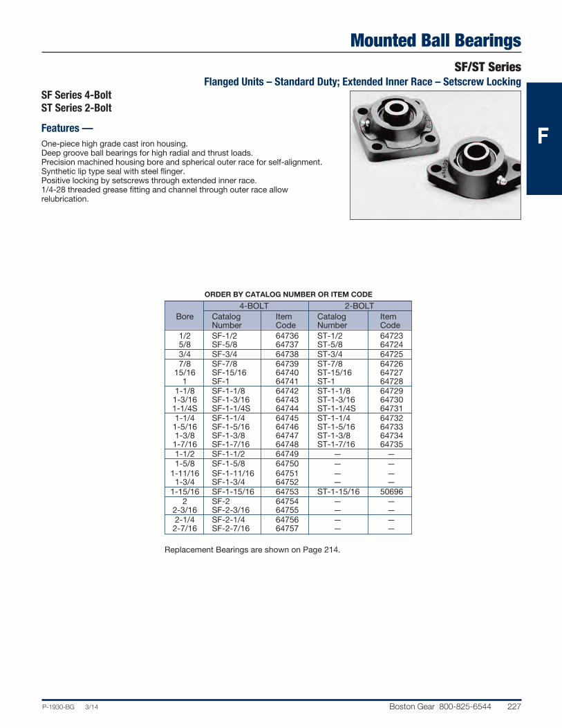
Mounted Ball BearingsSF/ST Series
Flanged Units – Standard Duty; Extended Inner Race – Setscrew Locking
P-1930-BG 3/14 Boston Gear 800-825-6544 227
SF Series 4-BoltST Series 2-Bolt
Features —One-piece high grade cast iron housing.Deep groove ball bearings for high radial and thrust loads.Precision machined housing bore and spherical outer race for self-alignment.Synthetic lip type seal with steel flinger.Positive locking by setscrews through extended inner race.1/4-28 threaded grease fitting and channel through outer race allow relubrication.
ORDER BY CATALOG NUMBER OR ITEM CODE
4-BOLT 2-BOLT Bore Catalog Item Catalog Item Number Code Number Code 1/2 SF-1/2 64736 ST-1/2 64723 5/8 SF-5/8 64737 ST-5/8 64724 3/4 SF-3/4 64738 ST-3/4 64725 7/8 SF-7/8 64739 ST-7/8 64726 15/16 SF-15/16 64740 ST-15/16 64727 1 SF-1 64741 ST-1 64728 1-1/8 SF-1-1/8 64742 ST-1-1/8 64729 1-3/16 SF-1-3/16 64743 ST-1-3/16 64730 1-1/4S SF-1-1/4S 64744 ST-1-1/4S 64731 1-1/4 SF-1-1/4 64745 ST-1-1/4 64732 1-5/16 SF-1-5/16 64746 ST-1-5/16 64733 1-3/8 SF-1-3/8 64747 ST-1-3/8 64734 1-7/16 SF-1-7/16 64748 ST-1-7/16 64735 1-1/2 SF-1-1/2 64749 — — 1-5/8 SF-1-5/8 64750 — — 1-11/16 SF-1-11/16 64751 — — 1-3/4 SF-1-3/4 64752 — — 1-15/16 SF-1-15/16 64753 ST-1-15/16 50696 2 SF-2 64754 — — 2-3/16 SF-2-3/16 64755 — — 2-1/4 SF-2-1/4 64756 — — 2-7/16 SF-2-7/16 64757 — —
Replacement Bearings are shown on Page 214.
F

Mounted Ball BearingsSF/ST SeriesFlanged Units – Standard Duty; Extended Inner
228 Boston Gear 800-825-6544 P-1930-BG 3/14
B
A
F
K R
C
PJ
D
ES
L
ASQUARE
BSQUARE
F
STANDARD TOLERANCES
DIMENSIONS TOLERANCE
Bore All +.0012 to –.0000
ENVELOPE AND BOLT SPACING DIMENSIONS IN INCHES
4-BOLT 2-BOLT Bore A B A B K 1/2 2-7/8 2-1/8 3-3/4 3 2-9/32 5/8 3/4 3-3/8 2-1/2 4-13/32 3-17/32 2-37/64 7/8 15/16 3-3/4 2-3/4 4-57/64 3-57/64 2-53/64 1 1-1/8 1-3/16 4-1/4 3-1/4 5-19/32 4-19/32 3-19/64 1-1/4S 1-1/4 1-5/16 4-5/8 3-5/8 6-1/8 5-1/8 3-11/64 1-3/8 1-7/16 1-1/2 5-1/8 4 — — — 1-5/8 1-11/16 5-3/8 4-1/8 — — — 1-3/4 1-15/16 5-5/8 4-3/8 7-7/16 6-3/16 4-9/16 2 6-3/8 5-1/8 — — — 2-3/16 2-1/4 6-7/8 5-5/8 — — — 2-7/16
ALL DIMENSIONS IN INCHES
R* Approx. Bore C D E F J L P Setscrew S Weight (Lbs.) Bolt UNF SF ST 1/2
7/16 1-1/16 1-17/64 3/8 2 9/32 31/32 10-32 5/8 .9 .9 5/8 3/4 1/2 1-7/32 1-31/64 3/8 2-1/4 1/2 1-11/64 10-32 23/32 1.7 1.2 7/8 15/16 9/16 1-1/4 1-9/16 7/16 2-1/2 9/16 1-11/32 10-32 25/32 2.0 1.6 1 1-1/8 1-3/16 9/16 1-11/32 1-11/16 7/16 2-15/16 5/8 1-39/64 1/4-28 7/8 2.7 2.11-1/4S 1-1/4 1-5/16
5/8 1-3/8 1-27/32 1/2 3-5/16 11/16 1-27/32 1/4-28 1 3.7 2.8 1-3/8 1-7/16 1-1/2 11/16 1-37/64 2-1/64 1/2 3-3/4 3/4 2-3/32 5/16-24 1-3/16 5.0 — 1-5/81-11/16 11/16 1-39/64 2-1/64 9/16 3-7/8 3/4 2-17/64 5/16-24 1-3/16 5.4 — 1-3/41-15/16 11/16 1-51/64 2-3/8 9/16 4-1/8 3/4 2-29/64 5/16-24 1-9/32 6.0 4.8 2
3/4 1-31/32 2-17/32 5/8 4-1/2 7/8 2-23/32 5/16-24 1-5/16 8.4 — 2-3/16 2-1/4
3/4 2-1/8 2-29/32 5/8 4-7/8 1 3-1/32 3/8-24 1-9/16 10.0 — 2-7/16
*2 AT 120°For Load Ratings, See Engineering Section, Page 237.
F

Mounted Ball BearingsMBF Series
Flanged Units – Medium Duty; Extended Inner Race – Setscrew Locking
P-1930-BG 3/14 Boston Gear 800-825-6544 229
STANDARD TOLERANCES
DIMENSIONS TOLERANCE
Bore 1-7/16-1-3/4 +.0010 to –.0000 1-15/16-3-1/2 +.0012 to –.0000
ALL DIMENSIONS IN INCHES
R* Approx. Bore A B C D E F J L P Setscrew S Weight Bolt UNF (Lbs.) 1-7/16 5-1/8 4 11/16 1-37/64 2-5/32 1/2 3-3/4 3/4 1-27/32 5/16-24 1-9/64 5.5 1-1/2 5-3/8 4-1/8 11/16 1-39/64 2-5/32 9/16 3-7/8 3/4 2-3/32 5/16-24 1-3/16 6.0 1-11/16 5-5/8 4-3/8 11/16 1-51/64 2-3/8 9/16 4-1/8 3/4 2-17/64 5/16-24 1-9/32 6.8 1-3/4 1-15/16 6-3/8 5-1/8 3/4 1-31/32 2-17/32 5/8 4-1/2 7/8 2-23/32 5/16-24 1-5/16 10.5 2 2-3/16 6-7/8 5-5/8 3/4 2-1/8 2-29/32 5/8 4-7/8 1 3-1/32 3/8-24 1-9/16 12.1 2-1/4 2-7/16 7-1/8 5-7/8 3/4 2-5/32 3-1/16 5/8 5-3/4 1-3/16 3-27/64 3/8-24 1-3/4 16.4 2-1/2 2-11/16 7-5/8 6 3/4 2-5/16 3-3/16 3/4 5-3/4 1-5/16 3-43/64 3/8-24 1-3/4 20.6 2-15/16 7-5/8 6 13/16 2-7/16 3-1/2 3/4 6-1/4 1-5/16 3-7/8 1/2-20 1-15/16 21.4 3 3-3/16 8-3/8 6-3/4 15/16 2-13/32 3-17/32 3/4 6-7/8 1-11/32 4-3/16 1/2-20 2-1/32 26.7 3-1/4 3-7/16 8-3/8 6-3/4 15/16 2-11/16 3-31/32 3/4 7 1-9/16 4-25/64 1/2-20 2-7/32 20.0 3-1/2
*2 AT 120°For Load Ratings, See Engineering Section, Page 237.Replacement Bearings are shown on Page 214.
ORDER BY CATALOG NUMBER OR ITEM CODE
Catalog Item Bore Number Code 1-7/16 MBF-1-7/16 64590 1-1/2 MBF-1-1/2 64591 1-11/16 MBF-1-11/16 64592 1-3/4 MBF-1-3/4 64593 1-15/16 MBF-1-15/16 64594 2 MBF-2 64595 2-3/16 MBF-2-3/16 64596 2-1/4 MBF-2-1/4 64597 2-7/16 MBF-2-7/16 64598 2-1/2 MBF-2-1/2 64599 2-11/16 MBF-2-11/16 64600 2-15/16 MBF-2-15/16 64601 3 MBF-3 64602 3-3/16 MBF-3-3/16 64603 3-1/4 MBF-3-1/4 64604 3-7/16 MBF-3-7/16 64605 3-1/2 MBF-3-1/2 64606
Features —One-piece high grade cast iron housing.Deep groove ball bearings for high radial and thrust loads.Precision machined housing bore and spherical outer race for full self-alignment.Synthetic lip type seal with steel flinger.Positive locking by setscrews through extended inner race.1/4-28 threaded grease fitting and channel through outer race allow relubrication.
R
C
PJ
D
ES L
ASQUARE
BSQUARE
F
F
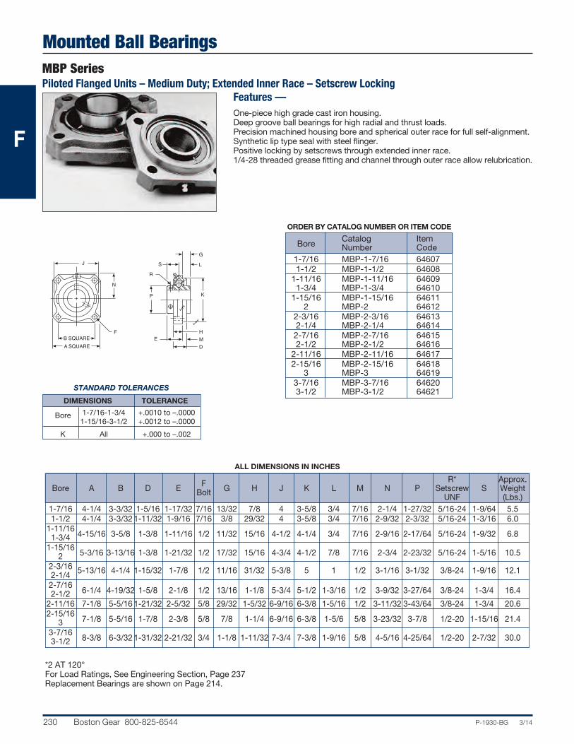
Mounted Ball BearingsMBP SeriesPiloted Flanged Units – Medium Duty; Extended Inner Race – Setscrew Locking
230 Boston Gear 800-825-6544 P-1930-BG 3/14
STANDARD TOLERANCES
DIMENSIONS TOLERANCE
Bore 1-7/16-1-3/4 +.0010 to –.0000 1-15/16-3-1/2 +.0012 to –.0000 K All +.000 to –.002
ALL DIMENSIONS IN INCHES
R* Approx. Bore A B D E F G H J K L M N P Setscrew S Weight Bolt UNF (Lbs.) 1-7/16 4-1/4 3-3/32 1-5/16 1-17/32 7/16 13/32 7/8 4 3-5/8 3/4 7/16 2-1/4 1-27/32 5/16-24 1-9/64 5.5 1-1/2 4-1/4 3-3/32 1-11/32 1-9/16 7/16 3/8 29/32 4 3-5/8 3/4 7/16 2-9/32 2-3/32 5/16-24 1-3/16 6.01-11/16
4-15/16 3-5/8 1-3/8 1-11/16 1/2 11/32 15/16 4-1/2 4-1/4 3/4 7/16 2-9/16 2-17/64 5/16-24 1-9/32 6.8 1-3/41-15/16
5-3/16 3-13/16 1-3/8 1-21/32 1/2 17/32 15/16 4-3/4 4-1/2 7/8 7/16 2-3/4 2-23/32 5/16-24 1-5/16 10.5 2 2-3/16 5-13/16 4-1/4 1-15/32 1-7/8 1/2 11/16 31/32 5-3/8 5 1 1/2 3-1/16 3-1/32 3/8-24 1-9/16 12.1 2-1/4 2-7/16
6-1/4 4-19/32 1-5/8 2-1/8 1/2 13/16 1-1/8 5-3/4 5-1/2 1-3/16 1/2 3-9/32 3-27/64 3/8-24 1-3/4 16.4 2-1/22-11/16 7-1/8 5-5/16 1-21/32 2-5/32 5/8 29/32 1-5/32 6-9/16 6-3/8 1-5/16 1/2 3-11/32 3-43/64 3/8-24 1-3/4 20.62-15/16
7-1/8 5-5/16 1-7/8 2-3/8 5/8 7/8 1-1/4 6-9/16 6-3/8 1-5/6 5/8 3-23/32 3-7/8 1/2-20 1-15/16 21.4 3 3-7/16
8-3/8 6-3/32 1-31/32 2-21/32 3/4 1-1/8 1-11/32 7-3/4 7-3/8 1-9/16 5/8 4-5/16 4-25/64 1/2-20 2-7/32 30.0 3-1/2
*2 AT 120°For Load Ratings, See Engineering Section, Page 237Replacement Bearings are shown on Page 214.
ORDER BY CATALOG NUMBER OR ITEM CODE
Catalog Item Bore Number Code 1-7/16 MBP-1-7/16 64607 1-1/2 MBP-1-1/2 64608 1-11/16 MBP-1-11/16 64609 1-3/4 MBP-1-3/4 64610 1-15/16 MBP-1-15/16 64611 2 MBP-2 64612 2-3/16 MBP-2-3/16 64613 2-1/4 MBP-2-1/4 64614 2-7/16 MBP-2-7/16 64615 2-1/2 MBP-2-1/2 64616 2-11/16 MBP-2-11/16 64617 2-15/16 MBP-2-15/16 64618 3 MBP-3 64619 3-7/16 MBP-3-7/16 64620 3-1/2 MBP-3-1/2 64621
Features —One-piece high grade cast iron housing.Deep groove ball bearings for high radial and thrust loads.Precision machined housing bore and spherical outer race for full self-alignment.Synthetic lip type seal with steel flinger.Positive locking by setscrews through extended inner race.1/4-28 threaded grease fitting and channel through outer race allow relubrication.
R
P K
DE
S L
F
N
B SQUAREA SQUARE
G
MH
J
F

Mounted Ball BearingsA Series
Adjustable Shaft Supports – Standard Duty; Eccentric Locking Collar
P-1930-BG 3/14 Boston Gear 800-825-6544 231
ALL DIMENSIONS IN INCHES
D G H Bore A B C Min. Max. E F Max. Min. Max.
1/2 7-1/8 5-1/8 3-1/8 2-13/32 6-1/16 4-7/8 2-3/4 7-7/16 2-1/2 3-21/32 5/8 3/4 7-1/8 5-1/8 3-1/8 2-17/32 6-1/16 4-7/8 2-3/4 7-9/16 2-13/16 3-17.32’ 7/8 15/16 8-1/4 6-1/4 3-3/4 2-25/32 7-1/16 5-11/16 3-1/8 8-11/16 3 4-9/32 1 1-1/8 1-3/16 11-1/4 8-1/8 4-1/2 3-1/2 9-15/16 7-11/16 4-3/8 11-25/32 3-7/16 6-7/161-1/4S
Bolt Bore K L M N O R S W Size 1/2 5/8 3-15/16 2-1/4 5/8 3/8 1-9/16 11/16 15/16 5/16 5/8 3/4 5/8 3-15/16 2-1/4 5/8 3/8 1-23/32 11/16 1-3/64 5/16 7/8 15/16 3/4 4-13/16 2-3/4 3/4 1/2 1-3/4 15/16 1-1/16 7/16 1 1-1/8 1-3/16 1 6-3/8 3-1/4 1-1/4 5/8 2-5/16 1-1/8 1-3/16 9/161-1/4S
NOTE: For applications where direction of radial bearing load is away from base, it is recommended that a hole be drilled near theend of each post and a suitable size pin inserted, as a safety precaution.
Replacement Bearings are shown on Page 213.
ORDER BY CATALOG NUMBER OR ITEM CODE
Catalog Item Bore Number Code 1/2 3A-1/2 07008 5/8 3A-5/8 07010 3/4 4A-3/4 07012 7/8 5A-7/8 07016 15/16 5A-15/16 07018 1 5A-1 07020 1-1/8 6A-1-1/8 07024 1-3/16 6A-1-3/16 07026 1-1/4S 6A-1-1/4S 07028
Features —Rigid one piece housing.Chrome alloy steel balls.Spherical outer race.Synthetic lip type seals.Eccentric locking collar.1/4-28 threaded grease fitting.
LB
EF
DMIN.
DMAX.
AG
H
O
SN
RW
MC
K
F
STANDARD TOLERANCES
DIMENSIONS TOLERANCE
Bore All +.001 to –.0000

Mounted BearingsTU SeriesTake-Up Frames
232 Boston Gear 800-825-6544 P-1930-BG 3/14
ALL DIMENSIONS IN INCHES
Pillow Block Adjust- F Bore ment B C D E Bolts G H K L R 6 16 17 1/2-1 9 19 20 1-3/4 2-5/8 3/8 1-5/8 3/16 5 2-1/8 1-3/4 12 22 23 6 19-1/8 20-1/4 1-1/8-1-3/4 9 22-1/8 23-1/4 2-3/8 3-1/8 1/2 2-1/8 1/4 6-9/16 2-11/16 2-3/16 12 25-1/8 26-1/4 18 31-1/8 32-1/4 9 25-5/16 26-9/16
1-15/16-2-7/16 12 28-5/16 29-9/16 3 4 5/8 2-3/4 5/16 8-5/32 3-5/16 2-3/4 18 34-5/16 35-9/16 24 40-5/16 41-9/16
Pillow Block Adjust- Bolts W Catalog Item Bore ment T T1 U V Min. Max. Y Z Number Code 6 15-1/4 TU816-6 29827 1/2-1 9 5/16 3/8 18-1/4 1-1/16 3 5 1-1/16 15/16 TU816-9 29828 12 21-1/4 TU816-12 29829 6 18-1/8 TU1828-6 29830 1-1/8-1-3/4 9 3/8 1/2 21-1/8 1-11/32 3-3/4 7-1/4 1-11/32 1-3/32 TU1828-9 29831 12 24-1/8 TU1828-12 19832 18 30-1/8 TU1828-18 29833 9 24-1/16 TU3139-9 29834
1-15/16-2-7/16 12 1/2 5/8 27-1/16 1-5/8 4-1/4 9 1-11/16 1-13/16 TU3139-12 29835 18 33-1/16 TU3139-18 29836 24 39-1/16 TU3139-24 29837
Boston Gear Take-up Frames are designed for use with Boston’s StandardDuty Pillow Blocks. Pillow Block units are not included.
Features —Bolted steel frame3 or 4 bolt frame mountingBolt hole centers adjustable
ORDER BY CATALOG NUMBER OR ITEM CODE
F

Engineering InformationAnalysis of Radial Bearing Loads for Unmounted and Mounted Rolling Elements
P-1930-BG 3/14 Boston Gear 800-825-6544 233
Radial Load
Radial bearing loads are determined by analysis of allthe forces applied to a shaft. In many instances thisbecomes a complex analysis and should be performedwith expertise. However, many applications involvesimple loading and may be calculated with basic information.
Many shafts are supported by two bearings, with a load“L” applied either between two bearings, as in Figure 1;or with load overhung, as in Figure 2. In either case, thereaction on the bearing is dependent upon:
a. The point of load application b. The magnitude of the load. c. The distance between the bearing centers.
With the above information known, the reactions, dueto the loads, on the bearings, may be calculated.
FIGURE 1.When the applied load is located between the twobearings, it is commonly referred to as “Straddle” loading.
FIGURE 2.
When the applied load is located outside the two bearings, it is commonly referred to as “Overhung”loading.
The loading of a shaft usually is the result of forcesgenerated by gearing, sprockets or pulleys, the weightof these parts and friction.
Normally the weight of the parts and friction areignored. However, if the weight of these parts is large,they should be considered.
In this text we are mainly considering radial loading ofthe shaft. Each load should be calculated individuallyas the sum of these will be used to calculate the loadimposed on the bearings.
Load Connection Factor
Loads applied by various types of drives may be calculated with use of the following load connectionfactors and formula:
2TKL = DL =Load (Lbs.)
(63025)(H.P.)T = Torque (Lb-Ins.) T = RPMK = Load Connection Factor
D = P.D. of Sprocket, Pinion, or Pulley (In.)
Load Connection Factors (K)
Sprocket or Timing Belt . . . . . . . . . . . . . . . . . . . . . 1.00Pinion and Gear Drive. . . . . . . . . . . . . . . . . . . . . . . 1.25Pulley and V-Belt Drive . . . . . . . . . . . . . . . . . . . . . 1.50Pulley and Flat-Belt Drive . . . . . . . . . . . . . . . . . . . . 2.50
Example “A”
Load smooth and steady 8 hours per day.
#40 Chain Drive30 Tooth Sprocket4.783 Sprocket P.D.2 HP500 RPM5/8 Shaft Dia.
With the above information the load can be calculatedas follows:
2TKL = D
63025 x 2T = = 252 In. Lbs. RPM
K = 1.0 From Load Connection Factor Table
D = 4.783
2 x 252 x 1.0L = 4.783
L =105 lbs. Radial Load
BEARING 1 BEARING 2
BEARING1
BEARING2
F
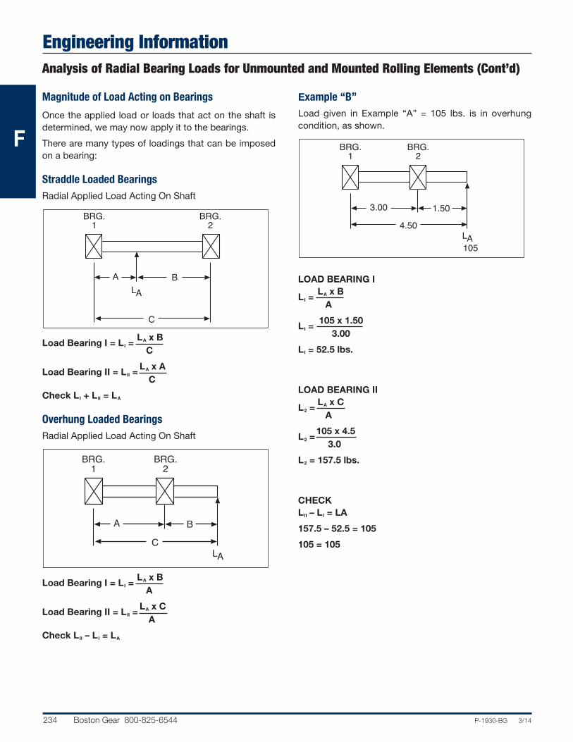
Engineering InformationAnalysis of Radial Bearing Loads for Unmounted and Mounted Rolling Elements (Cont’d)
234 Boston Gear 800-825-6544 P-1930-BG 3/14
Magnitude of Load Acting on Bearings
Once the applied load or loads that act on the shaft isdetermined, we may now apply it to the bearings.
There are many types of loadings that can be imposedon a bearing:
Straddle Loaded BearingsRadial Applied Load Acting On Shaft
LA x BLoad Bearing I = LI = C
LA x ALoad Bearing II = LII = C
Check LI + LII = LA
Overhung Loaded BearingsRadial Applied Load Acting On Shaft
LA x BLoad Bearing I = LI = A
LA x CLoad Bearing II = LII = A
Check LII – LI = LA
Example “B”Load given in Example “A” = 105 lbs. is in overhungcondition, as shown.
LOAD BEARING I LA x BLI = A
105 x 1.50LI = 3.00
LI = 52.5 lbs.
LOAD BEARING II LA x CL2 = A
105 x 4.5L2 = 3.0
L2 = 157.5 lbs.
CHECKLII – LI = LA
157.5 – 52.5 = 105
105 = 105
BRG.1
BRG.2
4.501.503.00
AL105
BRG.1
BRG.2
CBA
AL
BRG.1
BRG.2
C
BAAL
F

Engineering InformationBall and Mounted Ball Bearing Selection
P-1930-BG 3/14 Boston Gear 800-825-6544 235
Bearing selection for the majority of applications can bemade directly from the Load Rating Tables. Mountedbearings are listed individually on each page. Themounted bearings tables are located on Pages 108-109.
The following procedure may be followed:
1. Determine the actual radial load to be supported bythe bearing. For applications involving heavy shockloads or severe vibration, actual load should bemultiplied by a service factor from 1.1 to 1.5depending on the severity of these conditions.
2. Select a bearing from the table that has a radial loadrating equal to or greater than the actual radial loaddetermined in Step 1, for the life desired at therequired operating speed.
Ball bearing rating tables are based on an“Average” bearing life of 2500 hours. Average ormedium life (L50) is the life that may be expectedfrom 50% or more of a given group of bearingsoperating under an identical steady load condition.The minimum life (L10) is the life expectancy of atleast 90% of a group of bearings and is approxi-mately 1/5 average.
Example ‘C’
Using loading from Example “B,” select a mountedbearing suitable to give an average life (L50) of 15,000hours.
Known—
Load Bearing I = 52.5Load Bearing II = 157.5Shaft Diameter 5/8 (From Example “A”)Service Factor 1 (From Example “A”)500 RPM (From Example “A”)
From the Rating Table, Page 237, as shown, a standardduty bearing (either eccentric collar or extended setscrew inner race) may be selected.
Service Factor
Operating Conditions
.8 Uniform — not more than 15 minutes in 2 hours. 1.0 Moderate Shock — not more than 15 minutes in 2 hours.
Uniform — not more than 10 hours per day 1.25 Moderate Shock — not more than 10 hours per day.
Uniform — more than 10 hours per day. 1.50 Heavy Shock — not more than 15 minutes in 2 hours.
Moderate Shock — more than 10 hours per day. 1.75 Heavy Shock — not more than 10 hours per day. 2.0 Heavy Shock — more than 10 hours per day.
F

Engineering Information
236 Boston Gear 800-825-6544 P-1930-BG 3/14
Average Speed (R.P.M.) Shaft Life (L50) Radial Load (Pounds) Sizes Hours 50 100 500 1000 1500 1800 2000 2500 2,500 600 600 600 530 460 435 420 390 1/2 5,000 600 600 530 420 365 385 330 310 5/8 7,500 600 530 310 245 215 200 195 180 15,000 600 480 280 220 195 180 175 165 75,000 530 420 245 195 170 160 155 140 2,500 700 700 700 700 620 585 560 520 5,000 700 700 700 560 490 460 445 415 3/4 7,500 700 700 415 330 285 270 260 240 15,000 700 645 375 300 260 245 235 220 75,000 700 560 330 260 225 215 205 190 2,500 800 800 800 775 680 640 615 570 7/8 5,000 800 800 775 615 540 505 490 455 15/16 7,500 800 775 455 360 315 295 285 265 1 15,000 800 705 410 325 285 270 260 240 75,000 775 615 360 285 250 235 225 210 1-1/16 2,500 1100 1100 1100 1080 940 885 855 795 1-1/8 5,000 1100 1100 1080 855 750 700 680 630 1-3/16 7,500 1100 1080 630 500 435 410 395 370 1-1/4S 15,000 1100 980 570 455 395 375 360 335 75,000 1080 855 500 395 345 325 315 295 1-1/4 2,500 1400 1400 1400 1400 1245 1175 1130 1050 1-5/16 5,000 1400 1400 1400 1130 990 930 895 835 1-3/8 7,500 1400 1400 835 660 580 545 525 485 1-7/16 15,000 1400 1295 755 600 525 495 475 440 75,000 1400 1130 660 525 460 430 415 385
PS2 and PS3 Series Flanged Units
F
Average Speed (R.P.M.) Shaft Life (L50) Radial Load (Pounds) Sizes Hours 50 100 500 1000 1500 1800 2000 2500 2,500 300 300 300 300 300 300 300 300 1/2 5,000 300 300 300 300 300 300 300 300 5/8 7,500 300 300 300 245 215 200 195 180 15,000 300 300 280 220 195 180 175 165 75,000 300 300 245 195 170 160 155 140 2,500 350 350 350 350 350 350 350 350 5,000 350 350 350 350 350 350 350 350 3/4 7,500 350 350 350 330 285 270 260 240 15,000 350 350 350 300 260 245 235 220 75,000 350 350 350 260 225 215 205 190 2,500 400 400 400 400 400 400 400 400 7/8 5,000 400 400 400 400 400 400 400 400 15/16 7,500 400 400 400 360 315 295 285 265 1 15,000 400 400 400 325 285 270 260 240 75,000 400 400 360 285 250 235 225 210 1-1/16 2,500 600 600 600 600 600 600 600 600 1-1/8 5,000 600 600 600 600 600 600 600 600 1-3/16 7,500 600 600 600 500 435 410 395 370 1-1/4 15,000 600 600 570 455 395 375 360 335 75,000 600 600 500 395 345 325 315 295
Mounted Ball Bearing Radial Load Capacities Light DutyPS Series Pillow Blocks

Engineering InformationMounted Ball Bearing Radial Load Capacities
XL, S, H, L, F, T and MB Series
P-1930-BG 3/14 Boston Gear 800-825-6544 237
Series XL All
Speed (R.P.M.)
S (All) MB Radial Load (Pounds)
H-L-F-T (All) Average Shaft Shaft Life (L50) Size Size Hours 50 100 500 1000 1500 1800 2000 2500 3000 3600 4000 4500 5000 2,500 1580 1255 730 580 505 475 460 425 400 375 365 350 340 5,000 1255 995 580 460 400 375 365 340 320 300 290 275 270 1/2 7,500 730 580 340 270 235 220 210 195 185 175 170 160 155 5/8 — 15,000 665 525 305 245 210 200 195 180 170 160 155 145 140 75,000 580 460 270 210 185 175 170 155 150 140 135 130 125 2,500 1930 1530 895 710 620 585 560 520 490 460 445 430 415 5,000 1530 1215 710 560 490 460 445 415 390 365 355 335 330 3/4 — 7,500 895 710 415 330 285 270 260 240 225 215 205 200 190 15,000 810 645 375 300 260 245 235 220 205 195 185 180 175 75,000 710 560 330 260 225 215 205 190 180 170 165 155 150 2,500 2115 1675 980 775 680 640 615 570 540 505 490 470 455 7/8 5,000 1675 1330 775 615 540 505 490 455 425 400 385 370 360 15/16 — 7,500 980 775 455 360 315 295 285 265 250 235 225 215 210 1 15,000 890 705 410 325 285 270 260 240 225 210 205 195 190 75,000 775 615 360 285 250 235 225 190 200 185 180 170 165 2,500 2955 2340 1370 1085 945 890 860 800 750 705 685 655 1-1/8 5,000 2340 1855 1085 860 750 705 680 635 595 560 540 515 1-5/16 — 7,500 1370 1085 635 505 440 415 400 370 350 325 315 305 1-1/4S 15,000 1245 985 575 455 400 375 360 335 315 295 285 275 75,000 1085 860 505 400 350 325 315 295 275 260 250 240 1-1/4 2,500 3890 3085 1805 1430 1250 1175 1135 1055 990 930 900 1-5/16 5,000 3085 2445 1430 1135 990 930 900 835 785 740 715 1-3/8 — 7,500 1805 1430 835 665 580 545 525 490 460 430 415 1-7/16 15,000 1635 1300 760 600 525 495 475 445 415 390 380 75,000 1430 1135 665 525 460 430 415 385 365 340 330 2,500 4935 3915 2290 1815 1585 1495 1440 1335 1260 1180 5,000 3915 3105 1815 1440 1260 1180 1140 1060 1000 940 1-1/2 1-7/16 7,500 2290 1815 1060 845 735 690 665 620 585 550 15,000 2080 1605 965 765 665 630 605 565 530 500 75,000 1815 1440 845 665 585 550 530 490 465 435 2,500 5295 4200 2455 1950 1700 1600 1545 1435 1350 1-5/8 5,000 4200 3330 1950 1545 1350 1270 1225 1140 1070 1-11/16 1-1/2 7,500 2455 1950 1140 905 790 740 715 665 625 1-3/4 15,000 2230 1770 1035 820 715 675 650 605 570 75,000 1950 1545 905 715 625 590 570 530 500 2,500 5295 4200 2455 1950 1700 1600 1545 1435 1350 1-11/16 5,000 4200 3330 1950 1545 1350 1270 1225 1140 1070 1-15/16 1-3/4 7,500 2455 1950 1140 905 790 740 715 665 625 15,000 2230 1770 1035 820 715 675 650 605 570 75,000 1950 1545 905 715 625 590 570 530 500 2,500 6545 5190 3035 2410 2100 1980 1910 1775 2 1-15/16 5,000 5190 4120 2410 1910 1670 1570 1515 1410 2-3/16 2 7,500 3035 2410 1410 1120 975 915 885 825 15,000 2755 2190 1280 1015 885 835 805 745 75,000 2410 1910 1120 885 775 725 705 655 2,500 7910 6275 3670 2910 2540 2390 2310 2145 2-1/4 2-3/16 5,000 6275 4975 2910 2310 2020 1805 1830 1700 2-7/16 2-1/4 7,500 3670 2910 1700 1350 1180 1110 1070 995 15,000 3330 2645 1545 1225 1070 1010 970 905 75,000 2910 2310 1350 1070 935 880 850 790 2,500 9395 7455 4360 3455 3020 2840 2740 2545 2-7/16 5,000 7455 5910 3455 2740 2400 2250 2175 2020 — 2-1/2 7,500 4630 3455 2020 1605 1400 1315 1270 1180 15,000 3955 3140 1835 1455 1270 1200 1155 1075 75,000 3455 2740 1605 1270 1110 1045 1010 940 2,500 9990 7925 4635 3675 3210 3020 2915 2705 5,000 7925 6285 3675 2915 2550 2395 2310 2150 — 2-11/16 7,500 4635 3675 2150 1705 1490 1400 1350 1255 15,000 4210 3340 1950 1550 1350 1275 1230 1140 75,000 3675 2915 1705 1350 1180 1110 1075 995 2,500 11720 9300 5440 4315 3765 3545 3420 3175 2-15/16 5,000 9300 7375 4315 3420 2990 2810 2715 2525 — 3 7,500 5400 4315 2525 2000 1750 1645 1585 1475 15,000 4935 3920 2290 1820 1585 1495 1440 1340 75,000 4315 3420 2000 1585 1385 1305 1260 1170 2,500 12630 10020 5860 4645 4055 3820 3685 3420 3-3/16 5,000 10020 7945 4645 3685 3225 3025 2925 2720 — 3-1/4 7,500 5860 4645 2720 2160 1885 1770 1710 1590 15,000 5320 4225 2470 1960 1710 1610 1555 1445 75,000 4645 3685 2160 1710 1495 1405 1360 1260 2,500 14500 11505 6730 5335 4660 4385 4235 3930 3-7/16 5,000 11505 9125 5335 4235 3700 3475 3355 3120 — 3-1/2 7,500 6730 5335 3120 2480 2165 2035 1965 1825 15,000 6110 4850 2835 2250 1965 1850 1785 1655 75,000 5335 4235 2480 1965 1715 1615 1560 1450
F
These ball bearings will also accommodatethrust loads of up to 50% of the radial loadratings listed with no resultant decrease inthe radial load capacity. For ratings higherthan 5000 RPM, consult Factory.

Engineering InformationApplication Data – Unmounted Bearings
238 Boston Gear 800-825-6544 P-1930-BG 3/14
Lubrication
Either oil or grease can be used for lubricating bearings.Boston bearings are supplied slushed (open bearings)with a rust inhibiting oil, or prepacked with grease(sealed or shielded bearings) at the factory. However,special purpose lubricants can be used when required.It is recommended that bearing selection include consideration of the lubricant specifications andwhether the lubricant will be applied in service orprepacked at the factory. Good lubrication adds measurably to the life of a bearing.
Precautions
1. Keep bearings clean and protected with coveringuntil ready to install.
2. Make preliminary examination of shaft and housing forcorrect window size. Also check for chips, filings andburrs.
3. Press inner race on shaft or outer race in housingpreferably by use of arbor press. Never transmitmounting press forces through balls from one raceto the other.
4. Avoid hammer blows.
Shaft Rotating Shaft Stationary Bearing Shaft Theoretical Shaft TheoreticalBore Diameter Fit Diameter Fit Max. Min. Max. Min. Tight Loose Max. Min. Tight Loose .2500 .2495 .2500 .2495 .0005 .0005 .2495 .2490 .0000 .0010 .3125 .3120 .3125 .3120 .0005 .0005 .3120 .3115 .0000 .0010 .3750 .3745 .3750 .3745 .0005 .0005 .3745 .3740 .0000 .0010 .4375 .4370 .4375 .4370 .0005 .0005 .4370 .4365 .0000 .0010 .5000 .4995 .5000 .4995 .0005 .0005 .4995 .4990 .0000 .0010 .6250 .6245 .6250 .6245 .0005 .0005 .6245 .6240 .0000 .0010 .7500 .7495 .7500 .7495 .0005 .0005 .7495 .7490 .0000 .0010 .8750 .8745 .8752 .8747 .0007 .0003 .8745 .8740 .0000 .0010 1.0000 .9995 1.0002 .9997 .0007 .0003 .9995 .9990 .0000 .0010 1.1250 1.1245 1.1252 1.1247 .0007 .0003 1.1245 1.1240 .0000 .0010 1.2500 1.2405 1.2502 1.2497 .0007 .0003 1.2495 1.2490 .0000 .0010
Bearing Housing Rotating Housing Stationary Outside Housing Inside Theoretical Housing Inside TheoreticalDiameter Diameter Fit Diameter Fit
Max. Min. Max. Min. Tight Loose Max. Min. Tight Loose .6875 .6870 .6877 .6870 .0005 .0007 .6880 .6875 .0000 .0010 .8750 .8745 .8752 .8745 .0005 .0007 .8755 .8750 .0000 .0010 .9063 .9058 .0965 .9058 .0005 .0007 .9068 .9063 .0000 .0010 1.1250 1.1245 1.1252 1.1242 .0008 .0007 1.1255 1.1250 .0000 .0010 1.3750 1.3745 1.3752 1.3742 .0008 .0007 1.3755 1.3750 .0000 .0010 1.6250 1.6245 1.6252 1.6242 .0008 .0007 1.6258 2.6250 .0000 .0013 1.7500 1.7495 1.7502 1.7492 .0008 .0007 1.7508 1.7500 .0000 .0013 2.0000 1.9994 2.0002 1.9990 .0010 .0008 2.0010 2.0000 .0000 .0016 2.5000 2.4994 2.5002 2.4990 .0010 .0008 2.5010 2.5000 .0000 .0016 2.5625 2.5619 2.5627 2.5615 .0010 .0008 2.5635 2.5625 .0000 .0016
Note: 3000 Series Dim Are Nom. +.00057600 Series Dim Are Nom. +.0008
Recommended Housing Fits — 1600-3000-7500-7600 Series
Recommended Shaft Fits — 1600-3000-7500-7600 Series
F

Engineering InformationApplication Data – Mounted Bearings
P-1930-BG 3/14 Boston Gear 800-825-6544 239
Lubrication
Boston Gear ball and tapered roller bearing PillowBlocks and Flanged Cartridges are factory lubricatedprior to shipping. Those designed with the relubricationfeature periodically require grease during operation. Theinterval between relubrication and the amount necessary to insure a long operational l ife are determined by the specific application.
Loading, speed, and environmental conditions must beconsidered when determining the proper intervalbetween relubrication.
The table above may be used as a guide for establishinglubrication intervals for applications where contamination is not present.
For unusual operating conditions not covered by thetable, consult the factory for our recom men da tions.Normal bearing operation temperatures range from“cool-to-the-touch” to “too-hot-to-touch” for more thana few seconds, depending on the load, speed, andambient temperature.
The type of grease used in Boston bearing units allowssatisfactory operation at temperatures to 225°F andspeeds to 6500 RPM.
Bearings are prelubricated with a No. 2 consistencylithium base grease, and it is recommended that the LithEP-2 or an equivalent grease be used when relubrication is requierd. When relubricating bearings, itis preferable that the shaft be rotating. This rotation ofthe shaft will aid in preventing excessive filling andinsure proper distribution of the grease.
Grease should be added slowly to the bearing. When aslight bead appears from under the seal, the bearing willusually contain the proper amount of lubricant.
Precautions
The shaft must be clean, straight and free from nicks andburns and should fit the bearing as snugly as possible.Recommended shaft tolerance — Low Speed (or LightLoad) +.0 to –.002; Normal Speed (or Load) +.0 to –.001;High Speed (or Heavy Load) a light press fit is desirable.
The use of flats at setscrew locations will permit ease ofshaft removal.
Mounting
Setscrew Locking TypeHousing should be fastened to the mounting structure.Back out setscrews to clear shaft. After lubricating theshaft, slide it through the bearings and tightensetscrews to recommended torque, see Table below.
Eccentric Locking Collar TypeWhen sliding the shaft through the bore bearing innerring, be sure that the counterbore of eccentric collar “A”is toward eccentric boss “B” on inner ring.
Turn eccentric collar “A” in the direction in which theshaft will rotate. Hand tight is often sufficient but aspanner wrench or drift pin may be inserted in spannerwrench hole “C” and used to set the collar (Note: DONOT USE A DIRECT HAMMER BLOW to set the collaras such a blow may fracture the inner ring.) Not recommended for severe reversing applications.
Tighten set screw in eccentric collar firmly against shaftto recommended torque, see Table below.
NOTE: PS, PS2 and PS3 series: It is particularly important on these units that shaft be in placebefore the housing is secured to the mountingstructure. The self-aligning steel stampingsclamp the outer race when bolts are tightenedmaking further shaft alignment impossible.
Set Hex Width Tightening Screw Across Torque Diameter Flats (In.-Lbs.) 1/4 1/8 70 5/16 5/32 140 3/8 5/16 220 7/16 7/32 350 1/2 1/4 515 5/8 5/16 1200
Weeks Hours 1- 251- 501- 751- 1001- 1501- 2001- 2501Operated 250 500 750 1000 1500 2000 2500 3000 Per Day RPM RPM RPM RPM RPM RPM RPM RPM
8 12 12 10 7 5 4 3 2 16 12 7 5 4 2 2 1 1 24 10 5 3 2 1 1 1 1
F

Notes
240 Boston Gear 800-825-6544 P-1930-BG 3/14
F

Chains
P-1930-BG 3/14 Boston Gear 800-825-6544 241
Section Contents
ROLLER CHAINS
General Description . . . . . . . . . . . . . . . . . . . . . . . . . . . . . . . . . . . . . . . . . . . . . . . . . . . . . . . . . . . 242
Ordering Information . . . . . . . . . . . . . . . . . . . . . . . . . . . . . . . . . . . . . . . . . . . . . . . . . . . . . . . . . . 243
Multi-Strand Selection Charts . . . . . . . . . . . . . . . . . . . . . . . . . . . . . . . . . . . . . . . . . . . . . . . . . . . 244
Transmission Series . . . . . . . . . . . . . . . . . . . . . . . . . . . . . . . . . . . . . . . . . . . . . . . . . . . . . . . . . . . 245
Conveyor Series . . . . . . . . . . . . . . . . . . . . . . . . . . . . . . . . . . . . . . . . . . . . . . . . . . . . . . . . . . . . . . 245
Heavy Series . . . . . . . . . . . . . . . . . . . . . . . . . . . . . . . . . . . . . . . . . . . . . . . . . . . . . . . . . . . . . . . . . 245
Engineering . . . . . . . . . . . . . . . . . . . . . . . . . . . . . . . . . . . . . . . . . . . . . . . . . . . . . . . . . . . . . . 246-249
Roller Chain Attachments . . . . . . . . . . . . . . . . . . . . . . . . . . . . . . . . . . . . . . . . . . . . . . . . . . . . . . 251
Hollow Pin . . . . . . . . . . . . . . . . . . . . . . . . . . . . . . . . . . . . . . . . . . . . . . . . . . . . . . . . . . . . . . . . . . . 152
BLOCK CHAINS
Selection Charts/Dimensions . . . . . . . . . . . . . . . . . . . . . . . . . . . . . . . . . . . . . . . . . . . . . . . . . . . 253
LEAF (CABLE) CHAINS
Selection Charts/Dimensions . . . . . . . . . . . . . . . . . . . . . . . . . . . . . . . . . . . . . . . . . . . . . . . . . . . 253
LADDER CHAINS
Selection Charts/Dimensions . . . . . . . . . . . . . . . . . . . . . . . . . . . . . . . . . . . . . . . . . . . . . . . . . . . 254
MINIATURE ROLLER CHAINS
Selection Charts . . . . . . . . . . . . . . . . . . . . . . . . . . . . . . . . . . . . . . . . . . . . . . . . . . . . . . . . . . . . . . 255
CHAIN PULLERS/CHAIN BREAKING TOOLS
Selection Charts . . . . . . . . . . . . . . . . . . . . . . . . . . . . . . . . . . . . . . . . . . . . . . . . . . . . . . . . . . . . . . 256
G

Roller ChainsDescription of Roller Chain Parts
242 Boston Gear 800-825-6544 P-1930-BG 3/14
Chain DimensionsPrincipal dimensions of roller chain which identify the chain definitely are pitch, roller width, roller diameterand pin diameter.
PITCH is the linear distance from center to center of adjacent pins or rivets.
WIDTH is the distance between inside plates or length of roller.
DIAMETER is the actual outside diameter of roller (or pin).
Chain Types
Boston Roller chains can be furnished in two types— RIVETED and DETACHABLE.
RIVETED TYPERiveted type chains are recommendedfor high speed drives, as a greater rigidity of the pins and side plates issecured from this construction.
Rivited type is considered standard onthe smaller sizes up to and including3/4 “ pitch and will be supplied unlessDetachable type is specified.Detachable type chain is not recommended up to and including 5/8”pitch, but is available in cotter pin construction in 3/4” pitch.
DETACHABLE (Cottered) TYPEDetachable type chains are recommended for slower speed drives,especially in the larger pitches whereease of assembly and disassemblybecomes an important factor.
Detachable type with cotter pins is considered standard on all sizes 1”pitch and above and will be suppliedunless riveted type is specified. Bothtypes are available.
CONNECTING LINK(Spring Clip)
Standard for Nos. 25, 35, 40, 41, 50 and60 single and multiple-width chains.
CONNECTING LINK(Cotter Pin)
Standard for Nos. 80, 100, 120, 140, and160, 200 and 240 single and multiple-width chains.
ROLLER LINKFurnished as complete assemblies, rollerlinks are standard for all chain sizes. Thesame roller links are used for single andmultiple-width chains.
ONE PITCH OFFSET LINK(For standard service)
For use whenever chain length contains anodd number of pitches. These links arestandard for all chain sizes in single or multiple-widths. (Not available for 25 pitch.)
TWO PITCH OFFSET LINK(For severe service)
Consists of a roller link and an offset link riveted together. Two pitch offset assemblies should be specified for severeservice.
Chain Links
G

Roller ChainsOrdering Information
P-1930-BG 3/14 Boston Gear 800-825-6544 243
STEEL – SINGLE STRAND STEEL – TRIPLE STRAND
* Non Roller‡ Heavy Series chain has thicker link plates to resist shock
from pulsating loads.
HEAVY SERIES‡ Chain Standard Pitch & Package
Catalog Item
Number Quantities Number Code
3/4" - 60H 10' PKG 60H RIV - 10' 68994 60H DET - 10' 68981 1" - 80H 10' PKG 80H RIV - 10' 69077 80H DET - 10' 60979 1-1/4" - 100H 10' PKG 100H RIV - 10' 30958 100H DET - 10' 30956 1-1/2" - 120H 10' PKG 120H RIV - 10' 06401 120H DET - 10' 30960 1-3/4" - 140H 10'2-1/2" PKG 140HRIV-10'2-1/2" 50218 140HDET-10'2-1/2" 30962 2" - 160H 10' PKG 160H RIV - 10' 30234 160H DET - 10' 30964 2-1/2" - 200H 10' PKG 200H DET - 10' 58293
STANDARD CUT-TO-LENGTH CHAIN
—48 HOUR SERVICE—UP TO 50 STRANDS
Contact factory for larger quantitiesNo extra charge for this service!
Item Code Chain Pitch Quantity
30000 #25 cut to length 30042 #35 cut to length 30098 $40 cut to length 30236 #50 cut to length 30292 #60 cut to length 30224 #80 cut to length 68973 #41 cut to length
Chain Standard Pitch & Package
Catalog Item
Number Quantities Number Code
10' PKG. 25 - 10' 68948 1/4"-25* 100' REEL 25 100' 69010 250' REEL 25 - 250' 68950 500' REEL 25 - 500' 68951 10' PKG. 35 - 10' 68953 3/8" - 35* 100' REEL 35 - 100' 68954 250' REEL 35 - 250' 68955 500' REEL 35 - 500' 68956 10' PKG 40 - 10' 68959 1/2" - 40 100' REEL 40 - 100' 68960 250' REEL 40 - 250' 68961 10' PKG 41 - 10' 68964 1/2" - 41 100' REEL 41 - 100' 68965 250' REEL 41 - 250' 68966 500' REEL 41 - 500' 68967 1/2" - 43 10' PKG 43 - 10' 68947 10' PKG 50 - 10' 68984 5/8" - 50 100' REEL 50 - 100' 68985 250' REEL 50 - 250' 68986 10' PKG 60 RIV - 10' 68989 3/4" - 60 100' REEL 60 RIV - 100' 68990 10' PKG 60 DET -10' 68991 10' PKG 80 RIV - 10' 68808 1" - 80 50' REEL 80 RIV - 50' 29948 10 PKG 80 DET - 10' 68812 1-1/4" - 100 10’ PKG 100 RIV - 10' 68936 100 DET - 10' 68937
1-1/2" - 120 10' PKG 120 RIV - 10' 68940
120 DET - 10' 68941
1-3/4" - 140 10'2-1/2" PKG 140 RIV - 10'2-1/2" 30440
140 DET - 10'2-1/2" 30438 2" - 160 10' PKG 160 RIV - 10' 30462 160 DET - 10' 30460 2-1/4" - 180 10' PKG 180 RIV - 10' 50219 180 DET - 10' 30478
2-1/2" - 200 10' PKG 200 RIV - 10' 31066 200 DET - 10' 30488 3" - 240 5' PKG 240 RIV - 5' 50210 240 DET - 5' 58927
STEEL - DOUBLE STRAND
1/4" - 25-2* 10' PKG 25-2-10' 45886 3/8" - 35-2" 10' PKG 35-2-10' 69011 1/2" - 40-2 10' PKG 40-2-10' 69014 5/8" - 50-2 10' PKG 50-2-10' 69017
3/4" - 60-2 10' PKG 60-2 RIV - 10' 69020 60-2- DET - 10' 68935
1" - 80-2 10' PKG 80-2 RIV - 10' 68813 80-2 DET - 10' 68816 1-1/4" - 100-2 10' PKG 100-2 RIV - 10' 68938 100-2 DET - 10' 68939
1-1/2” - 120-2 10' PKG 120-2 RIV - 10' 68942 120-2 DET - 10' 68943
1-3/4" - 140-2 10'2-1/2" PKG 140-2RIV-10'2-1/2" 06085 140-2DET-10'2-1/2" 30448
2" - 160-2 10' PKG 160-2 RIV - 10' 50209 160-2 DET - 10' 30470 2-1/4" - 180-2 10' PKG 180-2 DET-10' 31014
2-1/2" - 200-2 5' PKG 200-2 RIV-5' 50220 200-2 DET-5' 30496
3" - 240-2 5' PKG 240-2 DET-5' 58301
Chain Standard Pitch & Package
Catalog Item
Number Quantities Number Code
1/4" - 25-3* 10' PKG 25-3-10' 45890 3/8" - 35-3* 10' PKG 35-3-10' 69057 1/2" - 40-3 10' PKG 40-3-10' 69060 5/8" - 50-3 10' PKG 50-3-10' 69063
3/4" - 60-3 10' PKG 60-3- RIV - 10' 69066
60-3 DET - 10' 68934
1" - 80-3 10' PKG 80-3 RIV - 10' 68818
80-3 DET - 10' 68822 1-1/4" - 100-3 10' PKG
100-3 RIV - 10' 69081 100-3 DET - 10' 69082
1-1/2" - 120-3 10' PKG 120-3 RIV - 10' 69083
120-3 DET - 10' 69087 1-3/4" - 140-3 10'2-1/2" PKG 140-3DET-10'2-1/2" 31142 2" - 160-3 5' PKG 160-3 DET-5' 31148 2-1/4" - 180-3 5' PKG 180-3 DET-5' 31160 2-1/2" - 200-3 5' PKG 200-3 DET-5' 30966 3" - 240-3 5' PKG 240-3 DET-5' 58304
STEEL - QUAD STRAND 3/8" - 35-4* 10' PKG 35-4-10' 68839 1/2" - 40-4 10' PKG 40-4-10' 68842 5/8" - 50-4 10' PKG 50-4-10' 68843
3/4" - 60-4 10' PKG 60-4 RIV - 10' 68932
60-4 DET - 10' 68933
1" - 80-4 10' PKG 100-4 RIV - 10' 50216
100-4 DET - 10' 31136 1-1/2" - 120-4 10' PKG 120-4 DET - 10' 31184 1-3/4" 140-4 5' PKG 140-4 DET - 5' 31190 2" - 160-4 5' PKG 160-4 DET - 5' 31154 2-1/2" - 200-4 5' PKG 200-4 DET - 5' 31172
STAINLESS STEEL 1/4" - 25* 10' PKG 25SS - 10' 58285 100' REEL 25SS - 100' 69056 3/8" - 35* 10' PKG 35SS - 10' 30078 1/2" - 40 10' PKG 40SS - 10' 30134 5/8" - 50 10' PKG 50SS - 10' 30272 3/4" - 60 10' PKG 60SS - 10' 30328
1" - 80 10' PKG 80SS RIV - 10' 13493
80SS DET - 10' 30366
NICKEL PLATED
1/4" - 25* 10' PKG 25NP - 10' 68709
100' REEL 25NP - 100' 68710
3/8" - 35* 10' PKG 35NP - 10' 68713
100' PKG 35NP - 100' 68714
1/2" - 40 10' PKG 40NP - 10' 68718
100' REEL 40NP - 100' 68719 10' PKG 50NP - 10' 68723 5/8" - 50 100' REEL 50NP - 100' 68724 250' REEL 50NP - 250' 68725 3/4" - 60 10' PKG 60NP - 10' 68723 100' REEL 60NP - 100' 68729
1" - 80 10' PKG 80NP - 10' 68732
G

Roller ChainsANSI StandardDouble, Triple and QuadrupleWidths Dimensions
244 Boston Gear 800-825-6544 P-1930-BG 3/14
ALL DIMENSIONS IN INCHES
PITCH
FG
B
CA
TEH
PITCH
FG
B
CA
T
EH
PITCH
FG
B
C
A
T
EH
PITCH
FG
B
C
AT
EH
H Average Avg. Chain Roller Pin Ultimate WeightNumber Pitch E Diam. A B C T F Diam. Strength Per Ft. G Lbs. Lbs.
SINGLE WIDTH 25* 1/4 .125 .130 .31 .19 .15 .030 .23 .0905 930 .104 35* 3/8 .187 .200 .47 .34 .23 .050 .36 .141 2,300 .21 40 1/2 .312 .312 .65 .42 .32 .060 .46 .156 3,700 .41 S41 1/2 .250 .306 .51 .37 .26 .050 .39 .141 2,580 .28 50 5/8 .375 .400 .79 .56 .40 .080 .59 .200 6,400 .69 60 3/4 .500 .468 .98 .64 .49 .094 .70 .234 8,700 .96 80 1 .625 .625 1.28 .74 .64 .125 .93 .312 15,500 1.60 100 101/4 .750 .750 1.54 .91 .77 .156 1.16 .375 24,000 2.56 120 1-1/2 1.000 .875 1.94 1.14 .97 .187 1.38 .437 34,000 3.60 140 1-3/4 1.000 1.000 2.08 1.22 1.04 .218 1.63 .500 46,000 4.90 160 2 1.250 1.125 2.48 1.46 1.24 .250 1.88 .562 58,000 6.40 180 2-1/4 1.406 1.406 2.81 1.74 1.40 .281 2.13 .687 80,000 8.70 200 2-1/2 1.500 1.562 3.02 1.86 1.51 .312 2.32 .781 95,000 10.30 240 3 1.875 1.875 3.76 2.27 1.88 .375 2.80 .937 130,000 16.90DOUBLE WIDTH 25-2* 1/4 .125 .130 .56 .31 .28 .030 .23 .0905 1,860 .20 35-2* 3/8 .187 .200 .86 .50 .43 .050 .36 .141 4,600 .41 40-2 1/2 .312 .312 1.20 .67 .60 .060 .46 .156 7,400 .81 50-2 5/8 .375 .400 1.49 .82 .75 .080 .59 .200 12,800 1.35 60-2 3/4 .500 .468 1.87 1..02 .93 .094 .70 .234 17,400 1.90 80-2 1 .625 .625 2.42 1.32 1.21 .125 .93 .312 31,000 3.15 100-2 1-1/4 .750 .750 2.94 1.62 1.47 .156 1.16 .375 48,000 5.00 120-2 1-1/2 1.000 .875 3.72 2.04 1.86 .187 1.38 .437 68,000 7.10 140-2 1-3/4 1.000 1.000 4.00 2.19 2.00 .218 1.63 .500 92,000 9.50 160-2 2 1.250 1.125 4.80 2.63 2.40 .250 1.88 .562 116,000 17.60 180-2 2-1/4 1.406 1.406 5.40 2.94 2.70 .281 2.13 .687 160,000 17.60 200-2 2-1/2 1.500 1.562 5.86 3.28 2.93 .312 2.32 .781 190,000 21.00 240-2 3 1.875 1.875 7.22 4.00 3.61 .375 2.80 .937 260,000 33.10TRIPLE WIDTH 25-3* 1/4 .125 .130 .81 .44 .41 .030 .23 .0905 2,790 .30 35-3* 3/8 .187 .200 1.26 .70 .63 .050 .36 .141 6,900 .60 40-3 1/2 .312 .312 1.78 .96 .89 .060 .46 .156 11,100 1.20 50-3 5/8 .375 .400 2.20 1.17 1.10 .080 .59 .200 19,200 2.05 60-3 3/4 .500 .468 2.75 1.46 1.37 .094 .70 .234 26,100 2.75 80-3 1 .625 .625 3.58 1.90 1.79 .125 .93 .312 46,500 4.80 100-3 1-1/4 .750 .750 4.35 2.33 2.18 .156 1.16 .375 72,000 7.30 120-3 1-1/2 1.000 .875 5.52 2.94 2.76 .187 1.38 .437 102,000 10.70 140-3 1-3/4 1.000 1.000 5.94 3.16 2.97 .218 1.63 .500 138,000 15.00 160-3 2 1.250 1.125 7.10 3.78 3.55 .250 1.88 .562 174,000 19.40 180-3 2-1/4 1.406 1.406 8.00 4.22 4.00 .281 2.13 .687 240,000 26.50 200-3 2-1/2 1.500 1.562 8.68 4.70 4.34 .312 2.32 .781 285,000 31.00 240-3 3 1.875 1.875 10.70 5.74 5.35 .375 2.80 .937 390,000 49.20QUADRUPLE WIDTH 25-4* 1/4 .125 .130 1.06 .56 .53 .030 .23 .0905 3,720 .45 35-4* 3/8 .187 .200 1.65 .90 .83 .050 .36 .141 9,200 .82 40-4 1/2 .312 .312 2.33 1.24 1.17 .060 .46 .156 14,800 1.60 50-4 5/8 .375 .400 2.91 1.53 1.45 .080 .59 .200 25,600 2.75 60-4 3/4 .500 .468 3.64 1.90 1.82 .094 .70 .234 34,800 3.70 80-4 1 .625 .625 4.73 2.47 2.37 .125 .93 .312 62,000 6.40 100-4 1-1/4 .750 .750 5.76 3.03 2.88 .156 1.16 .375 96,000 9.80 120-4 1-1/2 1.000 .875 7.30 3.83 3.65 .187 1.38 .437 136,000 14.20 140-4 1-4/4 1.000 1.000 7.86 4.12 3.93 .218 1.63 .500 184,000 20.00 160-4 2 1.250 1.125 9.40 4.93 4.70 .250 1.88 .562 232,000 25.00 180-4 2-1/4 1.406 1.406 10.58 5.52 5.29 .281 2.13 .687 320,000 35.00 200-4 2-1/2 1.500 1.562 11.50 6.10 5.75 .312 2.32 .781 380,000 41.50 240-4 3 1.875 1.875 14.14 7.47 7.07 .375 2.80 .937 520,000 65.00
*Non-Roller
G

Roller ChainsTransmission/Conveyor/Heavy Series
Double Pitch Dimensions
P-1930-BG 3/14 Boston Gear 800-825-6544 245
Transmission SeriesALL DIMENSIONS IN INCHES
Avg. Chain E H T G Avg. Wgt. Pitch Width Dia. A B C Thick- F Pin Ultimate PerNumber ness Dia. Strgth. Foot (Lbs.) Lbs.
2040 1 .312 .312 .65 .42 .32 .060 .46 .156 3,700 .30 2050 1-1/4 .375 .400 .79 .56 .40 .080 .59 .200 6,100 .45 2060 1-1/2 .500 .468 .98 .64 .49 .094 .69 .234 8,500 .68 2080 2 .625 .625 1.28 .74 .64 .125 .88 .312 14,500 1.11 2100 2-1/2 .750 .750 1.54 .91 .77 .156 1.16 .375 24,000 1.94
T
AH
PITCH
CB
E
FG
Heavy SeriesALL DIMENSIONS IN INCHES
Avg. Avg. Wgt. Chain Pitch E H A B C T F G Ultimate PerNumber Strgth. Foot (Lbs.) Lbs.
60H 3/4 .500 .468 1.11 .65 .55 .125 .680 .234 8,500 1.14 80H 1 .625 .625 1.41 .80 .70 .156 .930 .312 14,500 1.93 100H 1-1/4 .750 .750 1.67 .98 .83 .187 1.156 .375 24,000 3.06 120H 1-1/2 1.000 .875 2.07 1.21 1.03 .218 1.375 .437 34,000 4.45 140H 1-3/4 1.0001.000 2.20 1.28 1.10 .250 1.625 .500 46,000 5.68 160H 2 1.2501.125 2.60 1.52 1.30 .281 1.875 .562 58,000 7.33 180H 2-1/4 1.4061.406 2.95 1.75 1.48 .312 2.130 .687 80,000 9.10 200H 2-1/2 1.5001.562 3.63 2.02 1.66 .375 2.312 .781 95,000 13.50
Conveyor Series
ALL DIMENSIONS IN INCHES
Avg. weight per foot H Avg. (Lbs.) Chain Pitch E Over- A B C T F G Ultimate Over- Thermo-Number Std. Size Strgth. Std. size plastic Roller Roller (Lbs.) Roller Roller Roller C2040 1 .312 .312 .625 .65 .42 .32 .060 .46 .156 3,700 .32 .55 .33 C2050 1-1/4 .375 .400 .750 .79 .56 .40 .080 .59 .200 6,100 .53 .84 .54C2060H 1-1/2 .500 .468 .875 1.11 .65 .55 .125 .69 .234 8,500 .92 1.40 .94C2080H 2 .625 .625 1.125 1.41 .80 .70 .156 .88 .312 14,500 1.52 2.21 1.52C2100H 2-1/2 .750 .750 1.562 1.67 .98 .83 .187 1.15 .375 24,000 2.30 3.75 —C2120H 3 1.000 .875 1.750 2.07 1.21 1.03 .218 1.37 .437 34,000 3.70 5.71 —C2160H 4 1.250 1.125 2.250 2.60 1.52 1.30 .281 1.87 .562 58,000 5.85 8.93 —
AHCB
T
F
PITCH
G
E
T
PITCH
G
F
AHCB
E
STANDARD ROLLERSOVERSIZE ROLLERS G

Engineering InformationConveyor Chain Selection
246 Boston Gear 800-825-6544 P-1930-BG 3/14
Single or Double Pitch, Flat-Top and Hollow Pin ChainIn order to select a chain for a conveyor application, theVelocity and maximum Chain Pull must be established.The total pull may be obtained if the Torque and Sprocket PDare known, or if the Horsepower and Velocity can be determined.
2T Chain Pull, W = D
33000 P W = V
126050 P W = nD
If a pair of chains are used, the pull on each chain will be halfof the total chain pull.Having determine the Chain Pull, refer to Chain Load RatingCharts on Page 247 and select a chain with a capacity equalto or greater than the Chain Pull Required.To Calculate Chain Length (L):
For Single Pitch ChainL = 2C + N
For Double Pitch & Flat-Top Chain
NL = 2C + — 2
where: L = Chain Length, Pitches C = Center Distance, Pitches N = Number of Teeth in One Sprocket*
The computed value of L must be rounded out to a largerwhole number of pitches (links) for each complete chain. Anywhole number of links is satisfactory for Hinge-Top Chain butan even number should be selected for Single or Double Pitchor Flat-Top Chains.To obtain the center distance or chain length in inches, thevalue in pitches should be multiplied by the chain pitch.Example 1. Selecting a Double Pitch Conveying Chain.The power required to move material at 50 FPM is 1 Horsepower on a Conveyor with a Center Distance of 10 ft.
Step I: Determine Chain Pull:
33,000 P 33000 x 1 W = = = 660 Lbs. V 50
Step II: Refer to Conveyor Chain Load Rating Chart, page165. Select a double pitch chain with a WorkingLoad equal to or greater than 660 lbs. at 50 FPM. Selection — C2050 (1.25” Pitch) with 5/8 pitchsprockets 50B25 (or larger).
W = Chain Pull, Lbs.T = Torque, In. Lbs.D = Sprocket PD, InchesP = HorsepowerV = Chain Velocity, FPMn = Sprocket Speed, RPM{G
Step III: Determine Chain Length in Pitches. Convert CenterDistance (10 feet) to pitches.
10 x 12 C = = 96 Pitches 1.25
N Chain Length (L) = 2C + 2
25 Chain Length (L) = 2 x 96 + = 204.5 2
Adjust to next larger even whole number. Chain Length (L) = 206 Pitches
*Assuming same size Driver and Driven Sprockets.
Single Pitch & Double Pitch ChainFor horizontal conveyor applications where the HP or Torquedata is not available, the approximate Chain Pull can be calculated from the Weight to be moved (product and chain) and the Coefficient of Friction (between sliding surfaces of chain and supporting ways).
For Normal operation: Chain Pull W = (M = 2m) Cf W = Chain Pull Lbs. M = Product Weight, Lbs. per Ft. m = Chain Weight, Lbs. per Ft. C = Conveyor Length (between Centers), Ft. f = Coefficient of Friction (see Table).
For trial purposes, let m = 1.0 for other conveyor chains.
Note: The estimated weight of pins and/or attachments (perfoot of chain) should be included in chain weight.
Whenever the product becomes stalled on a moving conveyor, the chain pull is increased. The Added Pulldepends on the Stalled Weight (of product) and theCoefficient of Friction (between surfaces of product andchain).
For stalled product: Added Chain Pull, w = Mlf w = Added Chain Pull, Lbs. M = Product Weight, Lbs. per Ft. l = Length of Stalled Product, Ft. f = Coefficient of Friction (see Table).
For Stalled condition: Total Chain Pull = W = w, Lbs.
If a pair is used, the pull on each chain will be half of the totalchain pull.

Engineering InformationConveyor Chain Selection (Continued)
P-1930-BG 3/14 Boston Gear 800-825-6544 247
Example 2. A horizontal conveyor 25 Ft. long is to move aproduct weighing 200 Lbs. per Ft. at 20 FPM. Two FT2060Flat-Top chains will be used, if possible, with the thermoplasticplates supported on metal ways without lubrication.
Chain Pull, W = (M + 2m) Cf M = 200 Lbs. per Ft. m = 1.41 x 2 = 2.82 (two chains) C = 25 Ft. f = .25 + .15 = .40 (for starting with load) W = (200 + 5.64) 25 x .40 = 2056 Lbs.
The maximum working load of FT2060 chain at 20 FPM is1170 Lbs. (see table) and this will be adequate if the productcannot become stalled.
Note: Whenever two strands of chain are used, the total chainweight will be double the single strand weight, (per foot).
COEFFICIENT OF FRICTION FOR CONVEYOR CHAIN
Plate High Material Stainless Carbon Density
Impreg-
Stainless Steel Steel Delrin Nylon
Poly- nated
Steel ethylene Wood
Dry .41 .41 .30 .35 .15 .11 Water .35 .35 .25 .30 .12 .11Soap & Water .20 .20 .25 .20 .08 .11Carbon Steel
Dry .41 .39 .30 .35 .15 .11 Water .35 .35 .25 30 .12 .11 Soap .20 .20 .15 .20 .08 .11Acetal Plastic
Dry .30 .30 .20 Water .25 .25 .20Soap & Water .15 .15 .10 Nylon Dry .35 .35 .25 Water .30 .30 .25Soap & Water .20 .20 .12
SINGLE PITCH ROLLER CHAIN WITHATTACHMENTS
DOUBLE PITCH ROLLER CHAIN WITHATTACHMENTS
To select the proper chain, the working load or chain pull andthe chain speed in feet per minute must be known. Using thisinformation find the proper chain in the chart.† These load ratings are based on proper installation, lubrication andsteady load conditions.The minimum permissible number of sprocket teeth is 15 forsingle pitch, and 24 for double pitch chain. For smootheroperation, sprockets with greater numbers of teeth than theminimum are recommended.
CHAIN LOAD RATING CHART
*No. 35 Chain is a Rollerless Chain.
†For Hollow Pin chains, the working load (chain pull) should be multiplied by1.3 to obtain the proper value for use in selecting the chain pitch required.
Flat Top Conveyor Chain
MAXIMUM WORKING LOAD OR CHAIN PULL (LBS.)
Chain Chain Velocity — Feet Per Minute Type 0-10 20 30 40 50 70
FT2060 1070 1045 1035 1030 1025 1015
MAXIMUM WORKING LOAD OR CHAIN PULL (LBS.)
Chain Chain Velocity — Feet Per Minute Type 100 150 200 250 300 400
FT2060 1005 960 915 855 670 435
LUBRICATION - To assure maximum chain life, carbon andstainless steel chains should be lubricated wherever possible.Soap lubrication is recommended. Several detergent andnonalkali fluid types are on the market. Water lubricationshould be used when no other lubricant can be tolerated.Drip-type systems and wheel-type and sponge-type applicators are on the market.Delrin chain tends to be self-lubricating, although wear life canbe extended with the use of a lubricant, such as soap andwater.
Chain Numbers
Single 35* 40 50 60 80 100 120 160 Pitch Double C2040 C2050 C2060 C2080 C2100 C2120 C2160 Pitch Velocity of Chain (FPM) 25 250 443 690 995 1770 2760 3990 7100 50 243 432 675 970 1730 2690 3880 6900 75 233 414 645 930 1660 2580 3720 6630 100 220 391 610 880 1570 2440 3520 6250 125 206 366 570 820 1460 2280 3290 5850 150 190 338 528 760 1350 2110 3040 5400 175 175 311 485 700 1240 1940 2800 4970 200 160 284 444 640 1140 1770 2560 4550 225 146 259 405 584 1040 1620 2340 4150 250 133 236 368 530 940 1470 2120 3770 275 120 214 333 480 855 1330 1920 3310 300 110 195 305 440 780 1220 1760 3120 Standard Pitch Boston Sprockets To Operate With Above Chain Pitch 3/8” 1/2” 5/8” 3/4” 1” 1-1/4” 1-1/2” 2”
Maximum Working Load orChain Pull (Lbs.)
G

Engineering InformationConveyor Chain Working Load
248 Boston Gear 800-825-6544 P-1930-BG 3/14
At speeds of normal conveyor operation (less than 500feet per minute), chains are selected on the basis of safeworking load, rather than horsepower capacity. Workingload or chain pull of conveyor series chains is calculatedby multiplying the total combined weight of the chain,plus the conveyed material in any run, by the appropriatecoefficient of friction. In general, the maximum workingload for a conveyor chain will be higher than that deter mined for similar chains from a horsepower ratingtable. The higher load is permitted because there areusually fewer load cycles on a conveyor chain, comparedto a power transmission drive. In order to minimize wear,permissible working loads of conveyor chains arereduced as speeds increase. See the working load tablebelow.
Horizontal Conveyor LF (2W + M)P =
N
Vertical Conveyor
L (M + W)P = N
Inclined ConveyorA factor must be added to or subtracted from the chainload to compensate for raising or lowering the conveyedload on an inclined installation. This factor may be calculated by multiplying the weight of conveyed load bythe vertical change in feet, and dividing y the horizontalrun of the conveyor in feet.
LF (2W + M) cos φ ÷ LM sin φP = N
Vφ = ARC tan
L1
Carousel Conveyor (Plan View) forCrescent Top Chains
TF (W + M) + (TMF)P = N
Note: (TMF) is the length of stalled product.
Chain with Large Size Chain with Standard Size
Chain Rollers and Rolling Rollers and Sliding
Number
Friction Friction *Static Rolling *Static Sliding Dry Lubricated Dry Lubricated Dry Lubricated Dry LubricatedC-2040, C-2042 0.17 0.12 0.14 0.10C-2050, C-2052 0.16 0.11 0.13 0.09C-2060H, C-2062H 0.16 0.11 0.13 0.09C-2080H, C-2082H 0.15 0.10 0.12 0.08 .33 .24 .27 .21C-2100H, C-2102H 0.14 0.09 0.11 0.07C-2120H, C-2122H 0.14 0.09 0.11 0.07C-2160H, C-2162H 0.13 0.08 0.10 0.07
Chain Speed, feet per minute Chain Pitch
Number in 5 25 50 75 100 200 300 400 500
Inches Maximum Working Load, Lbs.
C-2040, C-2042 1 530 525 510 490 465 335 230 160 115C-2050, C-2052 1 1/4 870 865 840 805 765 555 380 265 190C-2060H,C-2062H 1 1/2 1215 1205 1170 1125 1065 775 530 370 265C-2080H,C-2082H 2 2070 2055 2000 1915 1815 1320 905 630 455C-2100H,C-2102H 2 1/2 3425 3400 3310 3175 3000 2180 1500 1040 750C-2120H,C-2122H 3 4855 4815 4690 4495 4250 3090 2125 1480 1065C-2160H,C-2162H 4 8585 8210 8000 7670 7250 5275 3625 2520 1815
RECOMMENDED MAXIMUM WORKING LOADS
COEFFICIENT OF FRICTION—DOUBLE PITCH ROLLER CHAINS
*For chain speed of 3 feet per minute or less
Calculate the working load for horizontal, inclined, vertical and carousel conveyors, substituting the following values in the appropriate formulas: P = Chain pull or working load S = Speed in feet per minute L = Length of conveyor in feet between sprocket
centers T = Total chain length in feet V = Vertical rise in feet F1 = Coefficient of friction, sliding F2 = Coefficient of friction, rolling W = Weight of chain and attachments per foot in
pounds M = Weight of conveyed product per foot in pounds N = Number of chain strands
L
L
L1
V
L
G

Engineering InformationRoller Chain Formulas
P-1930-BG 3/14 Boston Gear 800-825-6544 249
HorsepowerHorsepower equals 33,000 foot-pounds per minute, or550 foot-pounds per second. In terms of chain workingload or pull (P) and speed:
P x SHP = 33,000
P x Number of Teeth x Pitch x RPMHP = 396,000
Torque (lb.-in.) x RPMHP = 63,025
Torque (lb.-in.) x RPMHP = 5,252
Ratio Teeth in Large Sprocket Fast RPMRatio =
Teeth in Small Sprocket or
Slow RPM
Chain Working LoadWhen horsepower input is known, calculate for chainworking load or pull (P):
HP x 33,000P = FPM
HP x 396,000P = Number of Teeth x Pitch x RPM
TorqueP = Sprocket Pitch Radius
Sprocket Speed
12 x RPM
RPM = Number of Teeth x Pitch
Driver Teeth x Driver RPM RPM of Driven Sprocket = Driven Teeth
Driven Teeth x Driven RPM RPM of Driver Sprocket = Driver Teeth
Chain Speed Pitch x Number of Teeth x RPMSpeed (FPM) =
12
Factory of Safety Chain Ultimate StrengthFS=
Chain Working Load
Centrifugal Pull or TensionPull or tension caused by chain weight and velocity:
Chain Weight per Foot x (FPM)2Centrifugal Pull = 115,900
TorqueTorque =Sprocket Pitch Radius x Working Load
HP x 63,025Torque (lb.-in.) = RPM
HP x 5,252 Torque (lb.-ft.) = RPM
Chain Bearing PressureBearing Pressure Working Load(pounds per square inch) =
Bushing Length x Pin Dia.
Total Chain TensionTotal Chain Tension = Working Load + Centrifugal Pull
G

Notes
250 Boston Gear 800-825-6544 P-1930-BG 3/14
G

Roller Chain Attachments
P-1930-BG 3/14 Boston Gear 800-825-6544 251
Ordering ProcedureAttachments may be ordered as separate links or assembled in chains.
WHEN ORDERING SEPARATE ATTACHMENT LINKS, THE FOLLOWINGDATA MUST BE GIVEN:
1. Chain Number and Attachment Number.2. Connecting Link or Roller Link.
WHEN ORDER ATTACHMENTS ASSEMBLED* IN CHAIN, THE FOLLOWING INFORMATION MUST BE SUPPLIED:
1. Chain Number and Attachment Number.2. Spacing between Attachment Centers (Pitches or Inches). This must be a
multiple of the chain pitch.3. If spacing is an even number of pitches, attachments will be assembled as
pin links unless roller link style is specified.4. If spacing is an odd number of pitches, assembly will normally be supplied
with alternate pin and roller link attachments. For attachments to be on pin(or roller) links only, an offset link must be assembled in each interval.
*Riveted assembly will be supplied unless detachable links are specified.
ANSI Standard Roller Chains
Standard Roller Chain Attachments
Double Pitch Roller Chains
Double Pitch Chain Attachments
G

Roller ChainsHollow PinSingle and Double Pitch
252 Boston Gear 800-825-6544 P-1930-BG 3/14
Boston Gear Hollow Pin Chain is identical to ANSI Roller Chain in pitch, rollerwidth and roller diameter. It is quality designed for long wear life in conveyorapplications. The “hollow pin” feature provides unlimited conveyor design versatility. Stud, bushed design. Bushing diameter is same as comparable rollerchain.
ORDER BY CATALOG NUMBER OR ITEM CODE
Chain Pitch Standard and Package Catalog Item
Number Quantities Number Code
SINGLE PITCH 1/2" – 40HP 40HP – 20' 31088 5/8" – 50HP 20' Pkg. 50 HP – 20' 31092 3/4" – 60 HP 60 HP – 20" 31096 1" – 80 HP 80 HP – 20' 31100 DOUBLE PITCH — STANDARD ROLLERS 1" – C2040HP C2040HP – 20' 31104 1-1/4" – C2050HP 20' Pkg. C2050 HP – 20' 31108 1-1/2" – C2060 HP C2060 HP – 20" 31112 2" – C2080 HP C2080 HP – 20' 31116 DOUBLE PITCH — OVERSIZE ROLLERS 1" – C2042HP C2042HP – 20' 31104 1-1/4" – C2052HP 20' Pkg. C2052 HP – 20' 31108 1-1/2" – C2062 HP C2062 HP – 20" 31112 2" – C2082 HP C2082 HP – 20' 31116
F
E AHC
B
T
PITCH
G
DIMENSIONS IN INCHES
Average AverageChain Ultimate WeightPitch E H A B C T F G Strength Per Foot (Lbs.)
Single Double (Lbs.) Single Double
1/2 1 .312 .312 .65 .37 .32 .060 .46 .158 2500 .38 .31 5/8 1-1/4 .375 .400 .79 .46 .40 .080 .59 .203 3700 .63 .51 3/4 1-1/2 .500 .469 .97 .57 .49 .094 .69 .237 6100 .88 .75 1 2 .625 .625 1.22 .70 .61 .125 .88 .318 8500 1.56 1.33
G
PITCH
F
H E A
T
C
B
G

Block ChainBlock Chain*
P-1930-BG 3/14 Boston Gear 800-825-6544 253
Leaf (Cable) Chain
ORDER BY CATALOG NUMBER OR ITEM CODE
Chain Standard Package Catalog Item Number Quantities Number Code
B503 B503-25’ 30602 B504 25’ Pkg. B504-25’ 30608 B505 B505-25’ 30614 B506 B506-25’ 30620
STAINLESS STEEL Block Chain available on Special Order. Contact Factory.
ALL DIMENSIONS IN INCHES
From From Chain Pin Head Pin Head
Over-All Link Pin Average
No. Pitch W to to Width Plate Dia. Weight
C/L C/L C Thickness E Per Foot,
A B Riv. Sp Cl T (Lbs.)
B503 1 1/4 7/32 17/64 7/16 31/64 0.060 0.170 0.3 B504 1 5/16 9/32 5/16 9/16 19/32 0.080 0.187 0.4 B505 1 3/8 5/16 11/32 5/8 21/32 0.080 0.187 0.4 B506 1 1/2 3/8 13/32 3/4 25/32 0.080 0.187 0.5
*Refer to Page 290 for Block Chain Sprockets
ORDER BY CHAIN NUMBER AND LENGTH IN FEET
Average Weight Chain Lacing A G H T Ultimate Per Foot Chain
Pitch Strength (Lbs.) (Lbs.) Number
1/2 2 x 3 .50 .200 .455 .080 6,000 .48 BL-423 1/2 3 x 4 .67 .200 .455 .080 9,000 .64 BL-434 1/2 4 x 6 .92 .200 .455 .080 12,000 .93 BL-446 5/8 2 x 3 .58 .234 .585 .094 9,000 .74 BL-523 5/8 3 x 4 .78 .234 .585 .094 13,200 1.03 BL-534 5/8 3 x 4 1.07 .234 .585 .094 18,000 1.46 BL-546 3/4 2 x 3 .76 .312 .708 .125 13,200 1.15 BL-623 3/4 3 x 4 1.02 .312 .708 .125 20,400 1.60 BL-634 3/4 4 x 6 1.41 .312 .708 .125 26,400 2.30 BL-646 1 2 x 3 .94 .375 .950 .156 22,800 1.91 BL-823 1 3 x 4 1.26 .375 .950 .156 34,800 2.66 BL-834 1 4 x 6 1.41 .375 .950 .156 45,600 3.78 BL-846 1-1/4 2 x 3 1.12 .437 1.160 .187 31,200 2.95 BL-1023 1-1/4 3 x 4 1.60 .437 1.160 .187 49,200 4.07 BL-1034 1-1/4 4 x 6 2.08 .437 1.160 .187 62,400 5.79 BL-1046 1-1/2 2 x 3 1.27 .500 1.380 .220 40,800 4.15 BL-1223 1-1/2 3 x 4 1.73 .500 1.380 .220 66,000 5.82 BL-1234 1-1/2 4 x 6 2.42 .500 1.380 .220 81,600 8.27 BL-1246 1-3/4 2 x 3 1.46 .562 1.620 .250 51,600 5.57 BL-1423 1-3/4 3 x 4 1.98 .562 1.620 .250 85,200 7.73 BL-1434 1-3/4 4 x 6 2.76 .562 1.620 .250 103,200 11.01 BL-1446 2 2 x 3 1.68 .687 1.830 .281 78,000 7.51 BL-1623 2 3 x 4 2.22 .687 1.830 .281 118,800 10.45 BL-1634 2 4 x 6 4.17 .687 1.830 .281 156,000 14.85 BL-1646
When ordering chain with odd number of pitches specifywhether male or female end link required.
Boston Leaf Chains are designed for tension linkage applications such as counterweight chains for machine tools, elevator and oven doors, fork lift truckmasts, spinning frames, i.e. applications to lift or pull where it is not necessary toengage a sprocket.
Leaf chains normally run over sheaves and are attached to clevises at each end.Because of the wide variation in clevis designs, leaf chains are furnished less theend pins.
Not recommended for new applications.
G
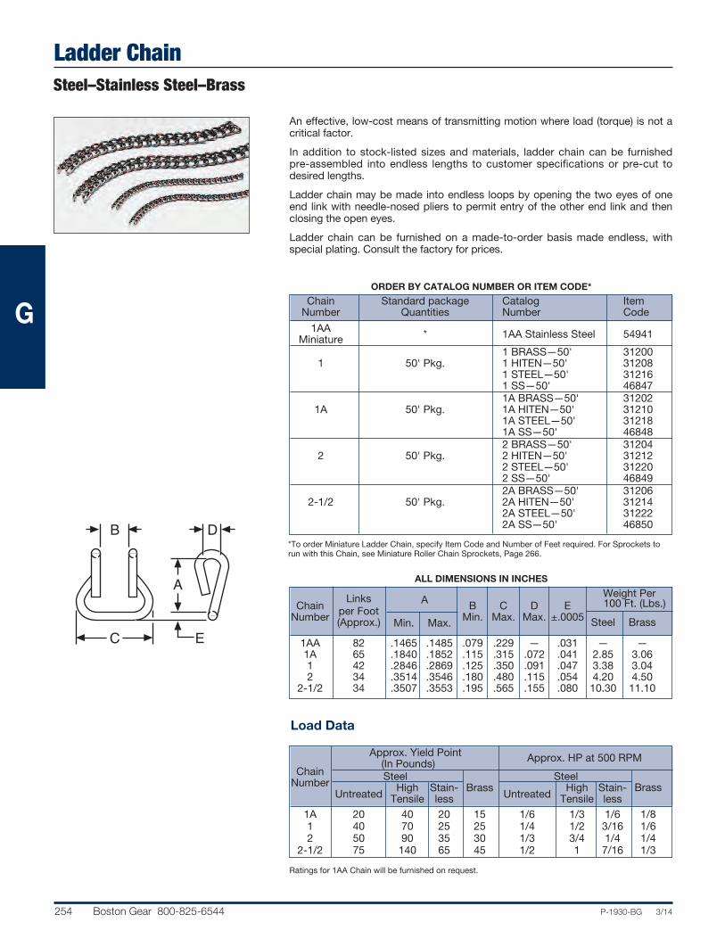
Ladder ChainSteel–Stainless Steel–Brass
254 Boston Gear 800-825-6544 P-1930-BG 3/14
ORDER BY CATALOG NUMBER OR ITEM CODE*
Chain Standard package Catalog Item Number Quantities Number Code
1AA * 1AA Stainless Steel 54941 Miniature 1 BRASS—50' 31200 1 50' Pkg. 1 HITEN—50' 31208 1 STEEL—50' 31216 1 SS—50' 46847 1A BRASS—50' 31202 1A 50' Pkg. 1A HITEN—50' 31210 1A STEEL—50' 31218 1A SS—50' 46848 2 BRASS—50' 31204 2 50' Pkg. 2 HITEN—50' 31212 2 STEEL—50' 31220 2 SS—50' 46849 2A BRASS—50' 31206 2-1/2 50' Pkg. 2A HITEN—50' 31214 2A STEEL—50' 31222 2A SS—50' 46850
An effective, low-cost means of transmitting motion where load (torque) is not acritical factor.
In addition to stock-listed sizes and materials, ladder chain can be furnished pre-assembled into endless lengths to customer specifications or pre-cut todesired lengths.
Ladder chain may be made into endless loops by opening the two eyes of oneend link with needle-nosed pliers to permit entry of the other end link and thenclosing the open eyes.
Ladder chain can be furnished on a made-to-order basis made endless, withspecial plating. Consult the factory for prices.
B D
A
EC
ALL DIMENSIONS IN INCHES
Weight Per Chain Links A B C D E 100 Ft. (Lbs.)Number per Foot Min. Max. Min. Max. Max. ±.0005 (Approx.) Steel Brass
1AA 82 .1465 .1485 .079 .229 — .031 — — 1A 65 .1840 .1852 .115 .315 .072 .041 2.85 3.06 1 42 .2846 .2869 .125 .350 .091 .047 3.38 3.04 2 34 .3514 .3546 .180 .480 .115 .054 4.20 4.50 2-1/2 34 .3507 .3553 .195 .565 .155 .080 10.30 11.10
*To order Miniature Ladder Chain, specify Item Code and Number of Feet required. For Sprockets torun with this Chain, see Miniature Roller Chain Sprockets, Page 266.
Approx. Yield Point (In Pounds) Approx. HP at 500 RPM
Chain Steel SteelNumber High Stain- Brass High Stain- Brass Untreated Tensile less Untreated Tensile less 1A 20 40 20 15 1/6 1/3 1/6 1/8 1 40 70 25 25 1/4 1/2 3/16 1/6 2 50 90 35 30 1/3 3/4 1/4 1/4 2-1/2 75 140 65 45 1/2 1 7/16 1/3
Load Data
Ratings for 1AA Chain will be furnished on request.
G
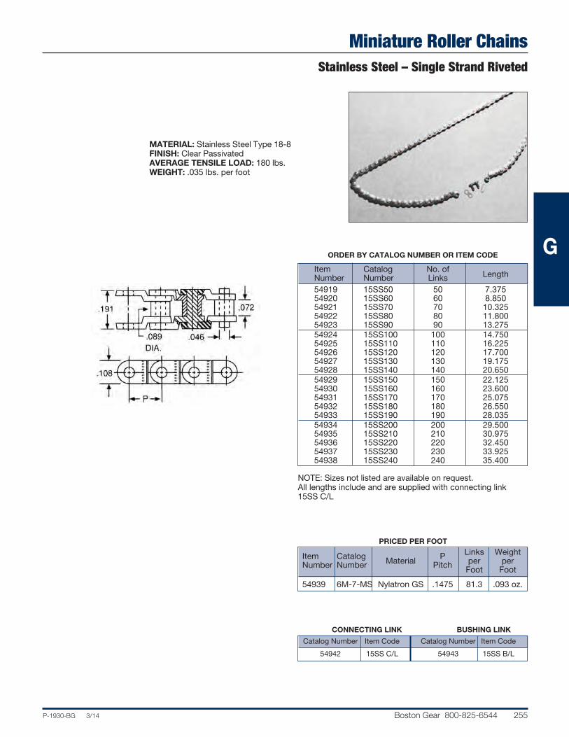
Miniature Roller ChainsStainless Steel – Single Strand Riveted
P-1930-BG 3/14 Boston Gear 800-825-6544 255
PRICED PER FOOT Links Weight Item Catalog Material P per per Number Number Pitch Foot Foot
54939 6M-7-MS Nylatron GS .1475 81.3 .093 oz.
MATERIAL: Stainless Steel Type 18-8FINISH: Clear PassivatedAVERAGE TENSILE LOAD: 180 lbs.WEIGHT: .035 lbs. per foot
Item Catalog No. of Number Number Links Length
54919 15SS50 50 7.375 54920 15SS60 60 8.850 54921 15SS70 70 10.325 54922 15SS80 80 11.800 54923 15SS90 90 13.275 54924 15SS100 100 14.750 54925 15SS110 110 16.225 54926 15SS120 120 17.700 54927 15SS130 130 19.175 54928 15SS140 140 20.650 54929 15SS150 150 22.125 54930 15SS160 160 23.600 54931 15SS170 170 25.075 54932 15SS180 180 26.550 54933 15SS190 190 28.035 54934 15SS200 200 29.500 54935 15SS210 210 30.975 54936 15SS220 220 32.450 54937 15SS230 230 33.925 54938 15SS240 240 35.400
NOTE: Sizes not listed are available on request. All lengths include and are supplied with connecting link15SS C/L
CONNECTING LINK BUSHING LINK
Catalog Number Item Code Catalog Number Item Code
54942 15SS C/L 54943 15SS B/L
ORDER BY CATALOG NUMBER OR ITEM CODE G

Chain Pullers
256 Boston Gear 800-825-6544 P-1930-BG 3/14
Chain Breaking Tools
The Boston Chain Puller was designed to make roller chaininstallation quick and easy.
To use: (1) hook the two jaws into each end of the chain; (2)turn the screw until the two ends almost meet; (3) insert theconnecting link and fasten.
ORDER BY CATALOG NUMBER OR ITEM CODE
Chain Jaw Catalog Item Sizes Spread Number Code Nos. 35-60 2" TH35-60 10784 80-240 5" TH80-240 10788
These Boston Chain Breaking Tools will disconnect any riveted roller chain manufactured to ANSI specifications, up toand including No. 100 (1-1/4” pitch).
Tool steel replaceable punch point, tempered for long life.
ORDER BY CATALOG NUMBER OR ITEM CODE
Chain Catalog Item Replaceable Points Sizes Number Code Catalog Number Item Code
Nos. 25-60 CBT-60 06800 XCBT 60-5 06808 60-100 CBT-100 63526 XCBT 100-5 63587
G

Sprockets
P-1930-BG 3/14 Boston Gear 800-825-6544 257
ROLLER CHAIN DRIVES
General Description ..................................................................................................................258-259
Horsepower Ratings Charts.....................................................................................................260-262
Selection Charts........................................................................................................................263-265
MINIATURE CHAIN SPROCKETS
Catalog Number Selections/Dimensions .......................................................................................266
ROLLER CHAIN SPROCKETS
Catalog Number Selections/Dimensions................................................................................267-289
BLOCK CHAIN SPROCKETS
Catalog Number Selections/Dimensions .......................................................................................290
LADDER CHAIN SPROCKETS
Catalog Number Selections/Dimensions................................................................................291-292
ROLLER CHAIN DRIVE TENSIONERS
Catalog Number Selections/Dimensions................................................................................293-296
IDLER SPROCKETS
Catalog Number Selections/Dimensions .......................................................................................293
Section ContentsH

Chain DrivesRoller Chain Sprockets
258 Boston Gear 800-825-6544 P-1930-BG 3/14
The following considerations are very important in the selection and application of roller chain drives:
HORSEPOWER RATINGS—This catalog lists HorsepowerRatings for ANSI Series, single pitch, single strand chains No.25 through No.160 (and lightweight machinery series No. 41).
Ratings are listed for various numbers of teeth and speeds ofsmaller sprocket. Ratings for intermediate numbers of teeth orRPM may be determined by interpolation. The ratings reflecta service factor of 1, a chain length of approximately 100pitches, the use of recommended lubrication methods and adrive arrangement where two aligned sprockets are mountedon parallel horizontal shafts. For maximum service life, sprockets with small numbers of teeth, operating at moderateto high speeds or near the rated horsepower should havehardened teeth. Approximately 15,000 hours of service life atfull load operation may be expected under these conditions.
NO. OF TEETH—It is good practice to select a pinion sprocket with no less than 17 Teeth, to assure 120° of chainwrap and minimize overhung load. However, certain conditions, i.e., space limitations, light loads, intermittent duty,etc. will permit the use of smaller pinions.
RATIO—Sprocket ratios should not exceed about 6 to 1 fornormal chain life.
HARDENED TEETH—Boston Gear steel sprockets can behardened. Consult the factory for recommended procedure.
CENTER DISTANCE—The correct center distance is veryimportant. In designing chain drives, it is important that theCenter Distance should be long enough to provide at least120° of chain wrap on the smaller sprocket.
RELATIVE SHAFT LOCATIONS—It is desirable that the linebetween the two shaft centers be as nearly horizontal as possible. If this line is more than 60° from the horizontal, special precautions should be taken.
Roller Chain Drive Selection
Boston roller chain sprockets are quality designed and built to ANSI specifications for superior fatigue resistance and long operational life in a host ofindustrial and process applications. Sprockets are available in a wide range ofmaterials and pitches, with or without hubs.
Types and Styles
Type A – No HubBoston standard Type A sprockets are stocked for all singlestrand Roller Chains up to 1" Pitch (#80 Chain).
Type B – Single HubBoston Steel—Type B Stock Bore sprockets are stocked for allsingle strand Roller Chains up to 1" Pitch (#80 Chain) and fordouble strand Roller Chains in 3/8, 1/2, 5/8 and 3/4" Pitches.
Boston Stainless Steel—Type B Stock Bore sprockets arestocked for single strand Roller Chain in 1/4, 3/8, and 1/2"pitches.
Boston Steel—Type B Bored-to-Size sprockets are stocked forsingle strand Roller Chain in 1/4, 3/8, 1/2, 5/8, 3/4, and 1" pitches.
Boston Type B sprockets are solid (one piece) construction insmall sizes, and two-piece design in larger numbers of teeth,see Chart.
Pitch Solid Two-Piece Size up to starting at 25 25B30 25B32 35 35B25 35B26 41 41B20 41B21 40 40B20 40B21 50 50B16 50B17 60 60B16 60B17 80 80B14 80B15
H
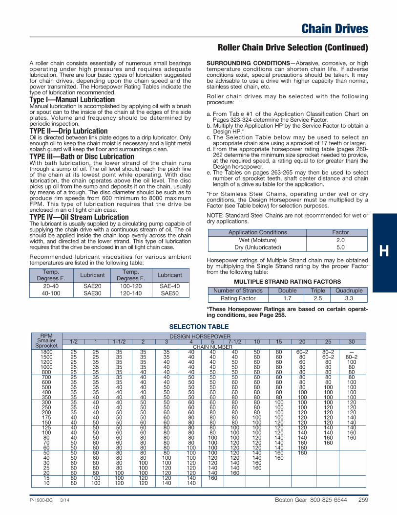
Chain DrivesRoller Chain Drive Selection (Continued)
P-1930-BG 3/14 Boston Gear 800-825-6544 259
A roller chain consists essentially of numerous small bearingsoperating under high pressures and requires adequate lubrication. There are four basic types of lubrication suggestedfor chain drives, depending upon the chain speed and thepower transmitted. The Horsepower Rating Tables indicate thetype of lubrication recommended.Type I—Manual LubricationManual lubrication is accomplished by applying oil with a brushor spout can to the inside of the chain at the edges of the sideplates. Volume and frequency should be determined by periodic inspection.TYPE II—Drip LubricationOil is directed between link plate edges to a drip lubricator. Onlyenough oil to keep the chain moist is necessary and a light metalsplash guard will keep the floor and surroundings clean.TYPE III—Bath or Disc LubricationWith bath lubrication, the lower strand of the chain runsthrough a sump of oil. The oil level should reach the pitch lineof the chain at its lowest point while operating. With disc lubrication, the chain operates above the oil level. The discpicks up oil from the sump and deposits it on the chain, usuallyby means of a trough. The disc diameter should be such as toproduce rim speeds from 600 minimum to 8000 maximumFPM. This type of lubrication requires that the drive beenclosed in an oil tight chain case.TYPE IV—Oil Stream LubricationThe lubricant is usually supplied by a circulating pump capable ofsupplying the chain drive with a continuous stream of oil. The oilshould be applied inside the chain loop evenly across the chainwidth, and directed at the lower strand. This type of lubricationrequires that the drive be enclosed in an oil tight chain case.
Recommended lubricant viscosities for various ambient temperatures are listed in the following table:
SURROUNDING CONDITIONS—Abrasive, corrosive, or hightemperature conditions can shorten chain life. If adverse conditions exist, special precautions should be taken. It maybe advisable to use a drive with higher capacity than normal,stainless steel chain, etc.
Roller chain drives may be selected with the following procedure:
a. From Table #1 of the Application Classification Chart onPages 323-324 determine the Service Factor.
b. Multiply the Application HP by the Service Factor to obtain aDesign HP.*
c. The Selection Table below may be used to select an appropriate chain size using a sprocket of 17 teeth or larger.
d. From the appropriate horsepower rating table (pages 260-262 determine the minimum size sprocket needed to provide,at the required speed, a rating equal to (or greater than) theDesign horsepower.
e. The Tables on pages 263-265 may then be used to selectnumber of sprocket teeth, shaft center distance and chainlength of a drive suitable for the application.
*For Stainless Steel Chains, operating under wet or dry conditions, the Design Horsepower must be multiplied by aFactor (see Table below) for selection purposes.
NOTE: Standard Steel Chains are not recommended for wet ordry applications.
Horsepower ratings of Multiple Strand chain may be obtainedby multiplying the Single Strand rating by the proper Factorfrom the following table:
MULTIPLE STRAND RATING FACTORS
*These Horsepower Ratings are based on certain operat-ing conditions, see Page 258.
Temp. Temp. Degrees F. Lubricant Degrees F. Lubricant
20-40 SAE20 100-120 SAE-40 40-100 SAE30 120-140 SAE50
Application Conditions Factor Wet (Moisture) 2.0 Dry (Unlubricated) 5.0
Number of Strands Double Triple Quadruple Rating Factor 1.7 2.5 3.3
RPM DESIGN HORSEPOWER Smaller 1/2 1 1-1/2 2 3 4 5 7-1/2 10 15 20 25 30 Sprocket CHAIN NUMBER 1800 25 25 35 35 35 40 40 40 50 80 60–2 80–2 — 1500 25 25 35 35 35 40 40 40 60 60 80 60–2 80–2 1200 25 35 35 35 40 40 40 50 60 60 60 80 100 1000 25 35 35 35 40 40 40 50 60 60 80 80 80 800 25 35 35 40 40 40 50 50 60 60 80 80 80 700 25 35 35 40 40 50 50 50 60 80 80 80 80 600 35 35 35 40 40 50 50 60 60 80 80 80 100 500 35 35 40 40 50 50 50 60 80 80 80 100 100 400 35 35 40 40 50 50 60 60 80 80 100 100 100 350 35 40 40 40 50 50 60 80 80 80 100 100 100 300 35 40 40 50 50 60 60 80 80 100 100 100 120 250 35 40 40 50 50 60 60 80 80 100 100 120 120 200 35 40 50 50 60 60 80 80 80 100 120 120 120 175 40 40 50 50 60 80 80 80 100 100 120 120 140 150 40 50 50 60 60 80 80 80 100 120 120 120 140 125 40 50 50 60 80 80 80 100 100 120 120 140 140 100 40 50 60 60 80 80 80 100 100 120 140 140 160 80 40 50 60 80 80 80 100 100 120 140 140 160 160 70 50 60 60 80 80 80 100 120 120 140 160 160 60 50 60 80 80 80 100 100 120 120 140 160 50 50 60 80 80 80 100 100 120 140 160 160 40 50 60 80 80 100 100 120 120 140 160 30 60 80 80 100 100 120 120 140 160 25 60 80 80 100 120 120 140 140 160 20 60 80 100 100 120 120 140 160 15 80 100 100 120 120 140 160 10 80 100 120 120 140 140
SELECTION TABLE
H

Roller Chain DrivesHorsepower Ratings for ANSI Roller ChainsSee Horsepower Ratings, page 259
260 Boston Gear 800-825-6544 P-1930-BG 3/14
SmallSprocket HP RATINGS—STANDARD SINGLE * STRAND ROLLER CHAIN—NO. 43-1/2” PITCH
RPMTeeth P.D. 10 20 30 40 50 75 100 125 150 175 200 250 300 350 400 500 600 900
11 1.77” .030 .056 .080 .11 .13 .18 .24 .29 .34 .39 .44 .54 .64 .73 .82 1.01 1.19 1.40 13 2.09 .036 .067 .096 .13 .15 .22 .28 .35 .41 .47 .53 .65 .76 .87 .99 1.21 1.42 1.70 15 2.41 .042 .078 .112 .15 .18 .26 .33 .40 .48 .55 .62 .75 .89 1.02 1.15 1.41 1.66 2.00 16 2.56 .045 .084 .120 .16 .19 .28 .36 .43 .52 .59 .67 .81 .96 1.10 1.23 1.51 1.78 2.28 18 2.88 .051 .095 .137 .18 .22 .31 .41 .49 .59 .67 .76 .92 1.09 1.25 1.41 1.72 2.02 2.80 20 3.20 .057 .106 .153 .20 .25 .35 .46 .55 .66 .75 .85 1.03 1.22 1.40 1.58 1.93 2.27 3.25 22 3.51 .063 .118 .170 .23 .27 .39 .51 .61 .73 .83 .94 1.15 1.35 1.55 1.75 2.14 2.52 3.62 24 3.83 .069 .130 .187 .25 .30 .43 .56 .67 .80 .91 1.03 1.26 1.48 1.70 1.92 2.35 2.76 3.97
Lubrication # Type I Type II Type III
SmallSprocket HP RATINGS—STANDARD SINGLE * STRAND ROLLER CHAIN—NO. 35-3/8” PITCH
RPMTeeth P.D. 10 20 30 50 75 100 125 150 200 250 300 400 600 900 1200 1500 1800 2500 3000
11 1.33” .023 .043 .062 .098 .14 .18 .22 .26 .34 .42 .49 .63 .91 1.32 1.72 2.08 2.47 3.32 2.93 13 1.57 .027 .051 .074 .117 .17 .22 .27 .31 .41 .50 .59 .76 1.09 1.59 2.05 2.49 2.96 3.98 3.76 15 1.80 .032 .060 .086 .136 .20 .26 .31 .37 .47 .58 .68 .89 1.28 1.85 2.40 2.91 3.45 4.64 4.66 17 2.04 .037 .068 .099 .156 .22 .29 .36 .42 .54 .66 .78 1.02 1.46 2.12 2.75 3.33 3.95 5.31 5.63 19 2.28 .042 .077 .111 .176 .25 .33 .40 .47 .61 .75 .88 1.15 1.65 2.39 3.10 3.76 4.46 5.99 6.65 21 2.52 .046 .086 .124 .196 .28 .37 .45 .53 .68 .83 .98 1.27 1.84 2.66 3.45 4.19 4.97 6.68 7.73 23 2.75 .051 .095 .137 .217 .31 .41 .49 .58 .75 .92 1.09 1.41 2.03 2.94 3.81 4.62 5.48 7.37 8.68 25 2.99 .055 .104 .150 .237 .34 .44 .54 .64 .82 1.01 1.19 1.54 2.22 3.21 4.16 5.06 6.00 8.06 9.50Lubrication # Type I Type II Type III
SmallSprocket HP RATINGS—STANDARD SINGLE * STRAND ROLLER CHAIN—NO. 41-1/2” PITCH
RPMTeeth P.D. 10 20 30 50 75 100 125 150 200 250 300 400 600 900 1200 1800 2400 3000
11 1.77” .030 .056 .080 .13 .18 .24 .29 .34 .44 .54 .64 .82 1.19 1.71 1.71 .093 .060 .043 13 2.09 .036 .067 .096 .15 .22 .28 .35 .41 .53 .65 .76 .99 1.42 2.05 2.20 1.20 0.78 0.56 15 2.40 .042 .078 .112 .18 .26 .33 .40 .48 .62 .75 .89 1.15 1.66 2.39 2.73 1.49 0.96 0.69 17 2.72 .048 .089 .128 .20 .29 .38 .46 .55 .71 .86 1.02 1.32 1.90 2.74 3.29 1.79 1.16 0.83 19 3.04 .054 .100 .145 .23 .33 .43 .52 .62 .80 .97 1.15 1.49 2.14 3.09 3.89 2.12 1.38 0.98 21 3.35 .060 .112 .161 .26 .37 .48 .58 .69 .89 1.09 1.28 1.66 2.39 3.44 4.46 2.46 1.60 1.14 23 3.67 .066 .124 .178 .28 .41 .53 .64 .76 .98 1.20 1.41 1.83 2.64 3.79 4.92 2.82 1.83 1.31 25 3.99 .072 .135 .195 .31 .44 .58 .70 .83 1.07 1.31 1.55 2.00 2.88 4.15 5.38 3.20 2.08 1.49Lubrication # Type I Type II Type III Type IV
*See Page 259 for Multiple Strand Rating Factor.#See Page 259 for Lubrication Details.RATINGS FOR INTERMEDIATE NUMBERS OF TEETH OR RPM MAY BE OBTAINED BY INTERPOLATION.
SmallSprocket HP RATINGS—STANDARD SINGLE * STRAND ROLLER CHAIN—NO. 25-1/4” PITCH
RPMTeeth P.D. 10 20 30 50 75 100 125 150 200 250 300 400 600 900 1200 1800 2500 3000 3500 4000
12 .97" .007 .014 .020 .032 .046 .059 .072 .085 .11 .24 .16 .21 .29 0.43 0.55 0.80 1.07 1.26 1.45 1.62 15 1.20 .009 .018 .025 .040 .058 .075 .092 .108 .14 .17 .20 .26 .38 0.54 0.70 1.01 1.36 1.61 1.85 2.08 17 1.36 .011 .020 .029 .046 .066 .086 .105 .124 .16 .20 .23 .30 .43 0.62 0.18 1.16 1.56 1.84 2.11 2.38 19 1.52 .012 .023 .033 .052 .075 .097 .119 .140 .18 .22 .26 .34 .49 0.70 0.91 1.31 1.76 2.07 2.38 2.69 20 1.60 .013 .024 .035 .055 .079 .103 .125 .148 .19 .23 .28 .36 .52 0.74 0.96 1.38 1.86 2.19 2.52 2.84Lubrication # Type I Type II
H

Roller Chain DrivesHorsepower Ratings for ANSI Roller Chains
See Horsepower Ratings, page 259
P-1930-BG 3/14 Boston Gear 800-825-6544 261
SmallSprocket HP RATINGS—STANDARD SINGLE * STRAND ROLLER CHAIN—NO. 40-1/2” PITCH
RPMTeeth P.D. 10 20 30 50 75 100 125 150 200 250 300 400 500 600 900 1200 1500 1800 2400 3000
11 1.77 .054 .10 .15 .23 .33 .43 .53 .62 .80 .98 1.16 1.50 1.84 2.16 3.11 4.03 4.93 4.66 3.03 2.17 13 2.09 .065 .12 .17 .28. .40 .52 .63 .74 .96 1.18 1.39 1.80 2.20 2.59 3.73 4.83 5.91 5.99 3.89 2.79 15 2.40 .076 .14 .20 .32 .46 .60 .74 .87 1.12 1.37 1.62 2.10 2.56 3.02 4.35 5.64 6.89 7.43 4.82 3.45 17 2.72 .087 .16 .23 .37 .53 .69 .84 .99 1.29 1.57 1.85 2.40 2.94 3.45 4.98 6.45 7.89 8.96 5.82 4.17 19 3.04 .098 .18 .26 .42 .60 .78 .95 1.12 1.45 1.77 2.09 2.71 3.31 3.90 5.62 7.27 8.89 10.5 6.88 4.92 21 3.35 .109 .20 .29 .46 .67 .87 1.06 1.25 1.62 1.98 2.33 3.02 3.69 4.34 6.26 8.11 9.91 11.7 7.99 5.72 23 3.67 .120 .22 .32 .51 .74 .96 1.17 1.38 1.78 2.18 2.57 3.33 4.07 4.79 6.90 8.94 10.9 12.9 9.16 6.55 25 3.99 .132 .25 .35 .56 .81 1.05 1.28 1.51 1.95 2.38 2.81 3.64 4.45 5.24 7.55 9.78 12.0 14.1 10.4 7.43Lubrication # Type I Type II Type III Type IV
SmallSprocket HP RATINGS—STANDARD SINGLE * STRAND ROLLER CHAIN—NO. 50-5/8” PITCH
RPMTeeth P.D. 10 20 30 50 75 100 125 150 200 250 300 400 600 900 1200 1500 1800 2100 2400 2700
11 2.22 .11 .20 .28 .45 .65 .84 1.03 1.21 1.56 1.91 2.25 2.92 4.21 6.07 7.86 7.44 5.58 4.42 3.62 3.04 13 2.61 .13 .24 .34 .54 .78 1.01 1.23 1.45 1.87 2.29 2.70 3.50 5.04 7.26 9.42 9.56 7.17 5.67 4.65 3.90 15 3.01 .15 .28 .40 .63 .90 1.17 1.43 1.69 2.19 2.67 3.15 4.08 5.88 8.48 11.0 11.9 8.89 7.03 5.76 4.83 17 3.40 .17 .32 .45 .72 1.04 1.34 1.64 1.93 2.50 3.06 3.60 4.67 6.73 9.70 12.6 14.3 10.7 8.48 6.95 5.83 19 3.80 .19 .36 .51 .81 1.17 1.51 1.85 2.18 2.82 3.45 4.06 5.27 7.59 10.9 14.2 16.9 12.7 10.0 8.22 6.89 21 4.19 .21 .40 .57 .90 1.30 1.69 2.06 2.43 3.15 3.85 4.53 5.87 8.46 12.2 15.8 19.3 14.7 11.6 9.55 8.01 23 4.59 .23 .44 .63 1.00 1.44 1.86 2.27 2.68 3.47 4.24 5.00 6.48 9.33 13.4 17.4 21.3 16.9 13.3 10.9 9.18
25 4.99 .26 .48 .69 1.09 1.57 2.04 2.49 2.93 3.80 4.64 5.47 7.09 10.2 14.7 19.1 23.3 19.1 15.1 12.4 10.4Lubrication # Type I Type II Type III Type IV
SmallSprocket HP RATINGS—STANDARD SINGLE * STRAND ROLLER CHAIN—NO. 60-3/4” PITCH
RPMTeeth P.D. 10 20 30 50 75 100 125 150 200 250 300 400 600 900 1200 1400 16001800 2000 2200 2400
11 2.66 .18 .34 .49 .78 1.11 1.44 1.76 2.07 2.69 3.29 3.87 5.02 7.23 10.5 11.9 9.45 7.70 6.49 5.51 4.78 4.20 13 3.13 .22 .41 .58 .93 1.33 1.72 2.11 2.48 3.22 3.94 4.64 6.01 8.65 12.5 15.3 12.1 9.89 8.34 7.08 6.14 5.39 15 3.61 .25 .47 .68 1.08 1.55 2.01 2.46 2.90 3.76 4.59 5.41 7.01 10.1 14.6 18.9 15.0 12.3 10.3 8.77 7.61 6.68 17 4.08 .29 .54 .78 1.24 1.78 2.30 2.82 3.32 4.31 5.26 6.20 8.03 11.6 16.7 21.7 18.2 14.8 12.5 10.6 9.18 8.06 19 4.56 .33 .61 .88 1.40 2.01 2.60 3.18 3.74 4.86 5.93 6.99 9.05 13.0 18.8 24.4 21.5 17.5 14.7 12.5 10.9 9.52 21 5.03 .37 .68 .98 1.56 2.24 2.89 3.54 4.17 5.41 6.61 7.78 10.1 14.5 21.0 27.2 24.9 20.3 17.1 14.5 12.6 11.1 23 5.51 .40 .75 1.08 1.72 2.47 3.19 3.91 4.60 5.97 7.29 8.59 11.1 16.0 23.2 30.2 28.6 23.3 19.6 16.7 14.4 12.7 25 5.98 .44 .82 1.18 1.88 2.70 3.49 4.28 5.04 6.53 7.98 9.40 12.2 17.5 25.4 32.9 32.4 26.4 22.3 18.9 16.4 14.4
Lubrication # Type I Type II Type III Type IV
SmallSprocket HP RATINGS—STANDARD SINGLE * STRAND ROLLER CHAIN—NO. 80-1” PITCH
RPMTeeth P.D. 10 20 30 50 75 100 125 150 200 250 300 400 600 900 1000 1200 1400 1600 1800 2000 2200
11 3.55 .42 .79 1.14 1.80 2.60 3.36 4.11 4.84 6.28 7.67 9.04 11.7 16.9 23.0 19.6 14.9 11.8 9.69 8.12 6.94 6.01 13 4.18 .51 .95 1.36 2.16 3.11 4.03 4.92 5.80 7.51 9.19 10.8 14.0 20.2 29.1 25.2 19.2 15.2 12.5 10.4 8.91 7.72 15 4.81 .59 1.10 1.59 2.52 3.63 4.70 5.75 6.77 8.77 10.7 12.6 16.4 23.6 34.0 31.2 23.8 18.9 15.4 12.9 11.0 9.57 17 5.44 .68 1.26 1.82 2.88 4.15 5.38 6.58 7.75 10.0 12.3 14.5 18.7 27.0 38.9 37.6 28.7 22.7 18.6 15.6 13.3 11.5 19 6.08 .76 1.43 2.05 3.25 4.68 6.07 7.42 8.74 11.3 13.8 16.3 21.1 30.4 43.8 44.5 33.9 26.9 22.0 18.4 15.7 13.6 21 6.71 .85 1.59 2.29 3.62 5.22 6.76 8.27 9.74 12.6 15.4 18.2 23.6 34.0 48.9 51.7 39.4 31.2 25.6 21.4 18.3 15.9 23 7.34 .94 1.75 2.52 4.00 5.76 7.46 9.12 10.7 13.9 17.0 20.0 26.0 37.4 53.9 59.2 45.1 35.8 29.3 24.6 21.0 18.2 25 7.98 1.03 1.92 2.76 4.38 6.30 8.17 9.98 11.8 15.2 18.6 21.9 28.4 40.9 59.0 64.9 51.1 40.6 33.2 27.8 23.8 20.6
Lubrication # Type I Type II Type III Type IV*See Page 259 for Multiple Strand Rating Factor.#See Page 259 for Lubrication Details.RATINGS FOR INTERMEDIATE NUMBERS OF TEETH OR RPM MAY BE OBTAINED BY INTERPOLATION.
H

Roller Chain DrivesHorsepower Ratings for ANSI Roller ChainsSee Horsepower Ratings, page 259
262 Boston Gear 800-825-6544 P-1930-BG 3/14
SmallSprocket HP RATINGS—STANDARD SINGLE * STRAND ROLLER CHAIN—NO. 120-1-1/2” PITCH
RPMTeeth P.D. 10 20 30 50 75 100 125 150 200 250 300 400 500 600 700 800 900 1000 1200
11 5.324 1.37 2.56 3.68 5.82 8.40 10.9 13.3 15.6 20.3 24.8 29.2 37.8 46.3 54.5 46.3 37.9 31.8 27.1 20.6 13 6.268 1.64 3.06 4.41 6.97 10.1 13.0 15.9 18.7 24.3 29.7 35.0 45.3 55.4 65.3 59.5 48.7 40.8 34.9 26.5 15 7.215 1.91 3.57 5.14 8.13 11.7 15.2 18.6 21.9 28.3 34.7 40.8 52.9 64.6 76.1 73.8 60.4 50.6 43.2 32.9 17 8.164 2.19 4.09 5.88 9.31 13.4 17.4 21.3 25.0 32.4 39.7 46.7 60.5 74.0 87.2 89.0 72.8 61.0 52.1 39.6 19 9.114 2.47 4.61 6.64 10.5 15.2 19.6 24.0 28.2 36.5 44.8 52.7 68.2 83.4 98.3 105 86.1 72.1 61.6 46.8 21 10.064 2.75 5.13 7.39 11.7 16.9 21.8 26.7 31.4 40.7 49.8 58.7 76.0 93.0 110 122 100 83.8 71.6 54.4
Lubrication #Type I Type II Type IV Type IV
SmallSprocket HP RATINGS—STANDARD SINGLE * STRAND ROLLER CHAIN—NO. 100-1-1/4” PITCH
RPMTeeth P.D. 10 20 30 50 75 100 125 150 200 250 300 400 500 600 900 1000 1200 1400
11 4.44 .81 1.51 2.18 3.45 4.97 6.44 7.88 9.28 12.0 14.7 17.3 22.4 27.4 32.3 27.5 23.4 17.8 14.2 13 5.22 .97 1.81 2.61 4.13 5.96 7.72 9.43 11.1 14.4 17.6 20.7 26.9 32.8 38.7 35.3 30.1 22.9 18.2 15 6.01 1.13 2.12 3.05 4.82 6.95 9.00 11.0 13.0 16.8 20.6 24.2 31.4 38.3 45.2 43.7 37.3 28.4 22.5 17 6.80 1.30 2.42 3.49 5.52 7.96 10.3 12.6 14.9 19.2 23.5 27.7 35.9 43.9 51.7 52.7 45.0 34.3 27.2 19 7.59 1.46 2.73 3.93 6.23 8.98 11.6 14.2 16.8 21.7 26.5 31.2 40.5 49.5 58.3 62.3 53.2 40.5 32.1 21 8.39 1.63 3.04 4.38 6.94 10.0 12.9 15.8 18.7 24.2 29.6 34.8 45.1 55.1 64.9 72.4 61.8 47.0 37.3 23 9.18 1.80 3.36 4.84 7.65 11.0 14.3 17.5 20.6 26.6 32.6 38.4 49.7 60.8 71.7 83.0 70.9 53.9 42.8 25 9.97 1.97 3.67 5.29 8.37 12.1 15.6 19.1 22.5 29.2 35.7 42.0 54.4 66.5 78.4 94.1 80.3 61.1 48.5Lubrication # Type I Type II Type III Type IV
SmallSprocket HP RATINGS—STANDARD SINGLE * STRAND ROLLER CHAIN—NO. 140-1-3/4” PITCH
RPMTeeth P.D. 10 20 30 50 75 100 125 150 200 250 300 400 500 600 700 800 900
11 6.211 2.13 3.97 5.72 9.06 13.1 16.9 20.7 24.4 31.5 38.6 45.5 58.9 72.0 65.8 52.4 42.9 35.9 13 7.312 2.55 4.74 6.83 10.9 15.6 20.3 24.7 29.2 37.8 46.2 54.4 70.5 86.2 84.6 67.3 55.1 46.2 15 8.417 2.98 5.56 8.01 12.7 18.3 23.7 28.9 34.1 44.1 54.0 63.6 82.4 101 105 83.4 68.3 57.2 17 9.523 3.41 6.36 9.16 14.5 20.9 27.1 33.1 39.0 50.5 61.7 72.8 94.2 115 126 100 82.4 69.1 19 10.632 3.84 7.17 10.3 16.0 23.5 30.5 37.3 44.0 57.0 70.0 82.1 106 130 149 119 97.4 81.6 21 11.742 4.28 7.98 11.5 18.2 26.2 34.0 41.5 49.0 63.4 77.6 91.4 118 145 171 138 113 94.8Lubrication # Type I Type II Type III Type IV
SmallSprocket HP RATINGS—STANDARD SINGLE * STRAND ROLLER CHAIN—NO. 160-2” PITCH
RPMTeeth P.D. 10 20 30 50 75 100 125 150 200 250 300 400 500 550 600
11 7.099 3.07 5.74 8.26 13.1 18.8 24.4 29.8 35.1 45.5 55.6 65.5 84.9 96.7 83.9 73.5 13 8.357 3.67 6.85 9.86 15.7 22.5 29.2 35.6 42.0 54.4 66.6 78.4 102 124 108 94.4 15 9.620 4.28 8.00 11.5 18.3 26.3 34.1 41.7 49.0 63.5 77.7 91.5 119 145 134 117 17 10.884 4.90 9.16 13.2 20.9 30.1 39.0 47.7 56.1 72.7 88.9 105 136 166 161 141 19 12.151 5.53 10.3 14.9 23.6 33.9 44.0 53.8 63.2 82.0 100 118 153 188 190 166 21 13.419 6.16 11.5 16.6 26.3 37.8 49.0 59.9 70.5 91.4 112 132 171 209 220 194Lubrication #Type I Type II Type III Type IV
*See Page 259 for Multiple Strand Rating Factor.#See Page 259 for Lubrication Details.RATINGS FOR INTERMEDIATE NUMBERS OF TEETH OR RPM MAY BE OBTAINED BY INTERPOLATION.
H

Roller Chain DrivesSelection
P-1930-BG 3/14 Boston Gear 800-825-6544 263
Teeth Driven Teeth on Driver Sprocket
Sprocket 11 12 13 14 15 16 17 18 19 20 21 22 23 24 25 1.36 1.25 1.15 1.07 1.00 15 6.469 7.235 6.993 7.748 7.500 26 28 28 20 30 1.45 1.33 1.23 1.14 1.07 1.00 16 7.207 6.971 7.736 7.494 8.249 8.000 28 28 30 30 32 32 1.55 1.42 1.31 1.21 1.13 1.06 1.00 17 7.943 7.710 7.473 8.237 7.994 8.749 8.500 30 30 30 32 32 34 34 1.64 1.50 1.38 1.29 1.20 1.13 1.06 1.00 18 7.669 8.446 8.212 7.975 8.737 8.495 9.249 9.000 30 32 32 32 34 34 36 36 1.73 1.58 1.46 1.36 1.27 1.19 1.12 1.06 1.00 19 8.404 8.174 8.949 8.714 8.477 9.238 8.995 9.749 9.500 32 32 34 34 34 36 36 38 38 1.82 1.67 1.54 1.43 1.33 1.25 1.18 1.11 1.05 1.00 20 8.124 8.909 8.679 9.452 9.216 8.978 9.739 9.495 10.249 10.000 32 34 34 36 36 36 38 38 40 40 1.91 1.75 1.61 1.50 1.40 1.31 1.24 1.17 1.11 1.05 1.00 21 8.857 8.632 9.414 9.183 9.955 9.718 9.479 10.239 9.995 10.749 10.500 34 34 36 36 38 38 38 40 40 42 42 2.00 1.83 1.69 1.57 1.47 1.37 1.29 1.22 1.16 1.10 1.05 1.00 22 9.590 9.365 9.139 9.918 9.686 10.457 10.220 9.980 10.740 10.496 11.249 11.000 36 36 36 38 38 40 40 40 42 42 44 44 2.09 1.92 1.77 1.64 1.53 1.44 1.35 1.28 1.21 1.15 1.10 1.05 1.00 23 9.304 10.098 9.872 9.645 10.422 10.189 10.959 10.721 10.481 11.240 10.996 11.749 11.500 36 38 38 38 40 40 42 42 42 44 44 46 46 2.18 2.00 1.85 1.72 1.69 1.50 1.41 1.33 1.26 1.20 1.14 1.09 1.04 1.00 24 10.037 9.815 10.605 10.378 10.150 10.926 10.692 11.461 11.222 10.982 11.741 11.496 12.249 12.000 38 38 40 40 40 42 42 44 44 44 46 46 48 48 2.27 2.08 1.92 1.79 1.67 1.56 1.47 1.39 1.31 1.25 1.19 1.14 1.09 1.04 1.00 25 9.744 10.547 10.324 11.112 10.884 10.654 11.429 11.195 11.963 11.723 11.483 12.241 11.996 12.750 12.500
38 40 40 42 42 42 44 44 46 46 46 48 48 50 50 2.72 2.50 2.31 2.14 2.00 1.88 1.76 1.67 1.58 1.50 1.43 1.36 1.30 1.25 1.20 30 11.345 12.161 11.943 12.746 12.522 12.299 13.087 12.858 13.638 13.406 13.172 13.942 13.705 14.469 14.228 44 46 46 48 48 48 50 50 52 52 52 54 54 56 56 2.91 2.66 2.46 2.28 2.14 2.00 1.88 1.78 1.68 1.60 1.52 1.45 1.39 1.33 1.28 32 12.812 12.597 12.379 13.188 12.967 13.765 13.539 13.314 14.099 13.869 14.646 14.413 14.178 14.946 14.708 48 48 48 50 50 52 52 52 54 54 56 56 56 58 58 3.18 2.92 2.69 2.50 2.33 2.19 2.06 1.94 1.84 1.75 1.67 1.59 1.52 1.46 1.40 35 13.976 13.761 13.546 14.361 14.141 13.921 14.721 14.497 15.288 15.061 14.833 15.613 15.382 16.155 15.921 52 52 52 54 54 54 56 56 58 58 58 60 60 62 62 3.27 3.00 2.77 2.57 2.40 2.25 2.12 2.00 1.89 1.80 1.71 1.64 1.56 1.50 1.44 36 13.668 14.495 14.279 14.063 14.874 14.653 14.433 15.230 15.006 15.795 15.567 15.338 16.117 15.886 16.658 52 54 54 54 56 56 56 58 58 60 60 60 62 62 64 3.64 3.34 3.08 2.86 2.67 2.50 2.35 2.22 2.10 2.00 1.90 1.82 1.74 1.67 1.60 40 15.561 15.349 15.136 15.961 15.746 15.528 16.339 16.119 16.920 16.697 16.473 17.262 17.035 17.818 17.588 58 58 58 60 60 60 62 62 64 64 64 66 66 68 68 3.82 3.50 3.23 3.00 2.80 2.62 2.47 2.34 2.21 2.10 2.00 1.91 1.83 1.75 1.68 42 15.983 15.773 16.605 16.391 16.177 16.994 16.777 16.557 17.364 17.142 17.939 17.714 17.489 18.275 18.047 60 60 62 62 62 64 64 64 66 66 68 68 68 70 70 4.09 3.75 3.46 3.22 3.00 2.81 2.65 2.50 2.37 2.25 2.14 2.04 1.96 1.88 1.80 45 17.139 16.930 16.719 17.553 17.340 18.161 17.945 17.728 18.536 18.317 18.096 18.895 18.671 19.463 19.237 64 64 64 66 66 68 68 68 70 70 70 72 72 74 74
RATIOCENTER DISTANCE - IN PITCHESCHAIN LENGTH - IN PITCHESTo obtain corresponding values inINCHES, multiply by the appropriateChain Pitch.
SPEED RATIOS - CENTER DISTANCES - CHAIN LENGTHS
For Center Distances other than listed in this Table, the Chain Length must be calculated, see Page 265.
H

Roller Chain DrivesSelection
264 Boston Gear 800-825-6544 P-1930-BG 3/14
Teeth Driven Teeth on Driver Sprocket
Sprocket 11 12 13 14 15 16 17 18 19 20 21 22 23 24 25 4.36 4.00 3.69 3.43 3.20 3.00 2.92 2.67 2.52 2.40 2.28 2.18 2.08 2.00 1.92 48 18.294 18.085 18.925 18.713 18.500 18.287 19.110 18.894 18.677 19.489 19.270 20.073 18.829 19.628 20.422 68 68 70 70 70 70 72 72 72 74 74 76 74 76 78 4.91 4.50 4.15 3.86 3.60 3.38 3.18 3.00 2.84 2.70 2.57 2.46 2.34 2.25 2.16 54 19.539 20.396 20.186 19.977 20.819 20.607 20.395 21.223 21.008 21.827 21.609 21.392 22.200 21.980 21.760 74 76 76 76 78 78 78 80 80 82 82 82 84 84 84 5.45 5.00 4.61 4.29 4.00 3.75 3.53 3.33 3.16 3.00 2.86 2.73 2.61 2.50 2.40 60 21.843 21.637 22.496 22.287 22.079 22.923 22.712 22.501 23.332 23.119 23.492 23.726 23.510 24.323 24.104 82 82 84 84 84 86 86 86 88 88 90 90 90 92 92 5.83 5.39 5.00 4.67 4.37 4.12 3.89 3.68 3.50 3.33 3.18 3.04 2.92 2.80 70 25.834 25.628 25.422 26.279 26.071 25.863 26.708 26.498 26.287 27.121 26.910 26.695 27.522 27.306 96 96 96 98 98 98 100 100 100 102 102 102 104 104
6.00 5.54 5.14 4.80 4.50 4.24 4.00 3.79 3.60 3.43 3.27 3.13 3.00 2.88 72 26.244 26.038 25.834 26.694 26.487 27.337 27.128 27.918 27.758 27.547 27.334 28.164 27.951 27.736 98 98 98 100 100 102 102 102 104 104 104 106 106 106
5.71 5.33 5.00 4.70 4.44 4.21 4.00 3.81 3.64 3.48 3.33 3.20 80 28.545 29.413 29.206 29.000 29.855 29.647 31.330 30.283 30.073 30.910 30.699 30.486 108 110 110 110 112 112 118 114 114 116 118 116
6.00 5.60 5.25 4.94 4.66 4.41 4.20 4.00 3.82 3.65 3.50 3.36 84 30.439 30.234 31.098 30.891 30.685 31.539 31.330 31.122 31.965 31.755 31.544 32.380 114 114 116 116 116 118 118 118 120 120 120 122 6.00 5.64 5.33 5.05 4.80 4.57 4.36 4.17 4.00 3.84 96 34.633 34.429 35.295 35.088 34.882 35.738 35.531 35.322 36.170 35.960 130 130 132 132 132 134 134 134 136 136
5.90 5.60 5.33 5.03 4.87 4.67 4.48 112 40.516 40.312 41.177 40.971 40.765 41.622 41.414 152 152 154 154 154 156 156
SPEED RATIOS - CENTER DISTANCES - CHAIN LENGTHS
H

Roller Chain DrivesSelection
Pitch Conversion Chart
P-1930-BG 3/14 Boston Gear 800-825-6544 265
No. Chain Pitch — Inches of 1/4 3/8 1/2 5/8 3/4 1 1-1/4 1-1/2 1-3/4 2 2-1/4 2-1/2 Pitches Chain Length — Feet 1 0.02 0.03 0.04 0.05 0.06 0.08 0.10 0.12 0.14 0.16 0.18 0.20 2 0.04 0.06 0.08 0.10 0.12 0.16 0.20 0.25 0.29 0.33 0.37 0.41 3 0.06 0.09 0.12 0.15 0.18 0.25 0.31 0.37 0.43 0.50 0.56 0.62 4 0.08 0.12 0.16 0.20 0.25 0.33 0.41 0.50 0.58 0.66 0.75 0.83 5 0.10 0.15 0.20 0.26 0.31 0.41 0.52 0.62 0.72 0.83 0.93 1.04 6 0.12 0.18 0.25 0.31 0.37 0.50 0.62 0.75 0.87 1.00 1.12 1.25 7 0.14 0.21 0.29 0.36 0.43 0.58 0.72 0.87 1.02 1.16 1.31 1.45 8 0.16 0.25 0.33 0.41 0.50 0.66 0.83 1.00 1.16 1.33 1.50 1.66 9 0.18 0.28 0.37 0.46 0.56 0.75 0.93 1.12 1.31 1.50 1.68 1.87 10 0.20 0.31 0.41 0.52 0.62 0.83 1.04 1.25 1.45 1.66 1.87 2.08 11 0.22 0.34 0.45 0.57 0.68 0.91 1.14 1.37 1.60 1.83 2.06 2.29 12 0.25 0.37 0.50 0.62 0.75 1.00 1.25 1.50 1.75 2.00 2.25 2.50 13 0.27 0.40 0.54 0.67 0.81 1.08 1.35 1.62 1.89 2.16 2.43 2.70 14 0.29 0.43 0.58 0.72 0.87 1.16 1.45 1.75 2.04 2.33 2.62 2.91 15 0.31 0.46 0.62 0.78 0.93 1.25 1.56 1.87 2.18 2.50 2.81 3.12 16 0.33 0.50 0.66 0.83 1.00 1.33 1.66 2.00 2.33 2.66 3.00 3.33 17 0.35 0.53 0.70 0.88 1.06 1.41 1.77 2.12 2.47 2.83 3.18 3.54 18 0.37 0.56 0.75 0.93 1.12 1.50 1.87 2.25 2.62 3.00 3.37 3.75 19 0.39 0.59 0.79 0.98 1.18 1.58 1.97 2.37 2.77 3.16 3.56 3.95 20 0.41 0.62 0.83 1.04 1.25 1.66 2.08 2.50 2.91 3.33 3.75 4.16 22 0.45 0.68 0.91 1.14 1.37 1.83 2.29 2.75 3.20 3.66 4.12 4.58 24 0.50 0.75 1.00 1.25 1.50 2.00 2.50 3.00 3.50 4.00 4.50 5.00 28 0.58 0.87 1.16 1.45 1.75 2.33 2.91 3.50 4.08 4.56 5.25 5.83 30 0.62 0.93 1.25 1.56 1.87 2.50 3.12 3.75 4.37 5.00 5.62 6.25 34 0.70 1.06 1.41 1.77 2.12 2.83 3.54 4.25 4.95 5.66 6.37 7.08
38 0.79 1.18 1.58 1.97 2.37 3.16 3.95 4.75 5.54 6.33 7.12 7.91 40 0.83 1.25 1.66 2.08 2.50 3.33 4.16 5.00 5.83 6.66 7.50 8.33 44 0.91 1.37 1.83 2.29 2.75 3.66 4.58 5.50 6.41 7.33 8.25 9.16 48 1.00 1.50 2.00 2.50 3.00 4.00 5.00 6.00 7.00 8.00 9.00 10.00 50 1.04 1.56 2.08 2.60 3.12 4.16 5.20 6.25 7.29 8.33 9.37 10.41 54 1.12 1.68 2.25 2.81 3.37 4.50 5.62 6.75 7.87 9.00 10.12 11.25 58 1.20 1.81 2.41 3.02 3.62 4.83 6.04 7.25 8.45 9.66 10.87 12.08 60 1.25 1.87 2.50 3.12 3.75 5.00 6.25 7.50 8.75 10.00 11.25 12.50 65 1.35 2.03 2.70 3.38 4.06 5.41 6.77 8.12 9.47 10.83 12.18 13.54 70 1.45 2.18 2.91 3.64 4.37 5.83 7.29 8.75 10.20 11.66 13.12 14.58 75 1.56 2.34 3.12 3.90 4.68 6.25 7.81 9.37 10.93 12.50 14.06 15.62 80 1.66 2.50 3.33 4.16 5.00 6.66 8.33 10.00 11.66 13.33 15.00 16.66 85 1.77 2.65 3.54 4.42 5.31 7.08 8.85 10.62 12.39 14.16 15.93 17.70 90 1.87 2.81 3.75 4.68 5.62 7.50 9.37 11.25 13.12 15.00 16.87 18.75 95 1.97 2.96 3.95 4.94 5.93 7.91 9.89 11.87 13.85 15.83 17.81 19.79 100 2.08 3.12 4.16 5.20 6.25 8.33 10.41 12.50 14.58 16.66 18.75 20.83
TO DETERMINE CHAIN LENGTH IN PITCHES(Approximately):
Chain Length in Pitches = 2 x CD (inches) + Teeth in Driver & Driven + Constant( Pitch ) ( 2 )Add for Ratio up to 4 : 1=12Constant 4 to 6: 1=4
6 to 8: 1=6
This chart gives chain length in feet when number of pitches and chain pitch (in inches) is known
{ }
H

Miniature Chain SprocketsSingle Strand.1475 Pitch; Plastic and Stainless Steel
266 Boston Gear 800-825-6544 P-1930-BG 3/14
ALL DIMENSIONS IN INCHESORDER BY CATALOG NUMBER OR ITEM CODE
No. Length of
Pitch Hub O.D. thru
Catalog Item
Teeth Dia. Bore Dia.
Bore Number Code
TYPE B SINGLE HUB PLASTIC (NYLATRON GS) 7 .340 .093 3/16 .392 15BP7 54144 8 .385 7/32 .437 15BP8 54145 9 .431 .1250 .483 15BP9 54146 10 .477 1/4 .529 15BP10 54147 12 .570 .622 15BP12 54148 13 .616 .668 15BP13 54149 14 .663 3/8 .715 15BP14 54150 15 .709 .761 15BP15 54151 16 .756 .1875 .808 15BP16 54152 17 .803 1/2 .855 15BP17 54153 18 .849 .901 15BP18 54154 19 .890 .948 15BP19 54155 20 .943 .995 15BP20 54156 21 .990 1.042 15BP21 54157 22 1.036 1.088 15BP22 54158 23 1.083 1.135 15BP23 54159 24 1.130 1.182 3/8 15BP24 54160 25 1.177 1.228 15BP25 54161 26 1.224 1.276 15BP26 54162 27 1.270 1.322 15BP27 54163 28 1.317 1.369 15BP28 54164 29 1.364 1.416 15BP29 54165 30 1.411 1.463 15BP30 54166 31 1.458 .250 5/8 1.510 15BP31 54167 32 1.505 1.557 15BP32 54168 33 1.552 1.604 15BP33 54169 34 1.598 1.650 15BP34 54170 35 1.645 1.697 15BP35 54171 36 1.692 1.744 15BP36 54172 38 1.786 1.838 15BP38 54173 40 1.880 1.922 15BP40 54174 42 1.974 2.026 15BP42 54175 44 2.068 2.120 15BP44 54176 52 2.443 2.495 15BP52 54177TYPE B SINGLE HUB STAINLESS STEEL (TYPE 303 – CLEAR PASSIVATED) 7 .340 .0937 15/64* .392 15BSS7 54178 8 .385 9/32* .437 15BSS8 54179 9 .431 .1250 21/64* .483 15BSS9 54180 10 .477 3/8* .529 11/32 15BSS10 54181 12 .570 25/64 .622 15BSS12 54182 15 .709 17/32 .761 15BSS15 54183 16 .756 .1875 9/16 .808 15BSS16 54184 18 .849 21/32 .901 15BSS18 54185 20 .943 .995 15BSS20 54186 24 1.130 1.182 15BSS24 54187 28 1.317 1.369 15BSS28 54188 30 1.411 3/4 1.463 13/32 15BSS30 54189 34 1.598 .2500 1.650 15BSS34 54190 36 1.692 1.744 15BSS36 54191 40 1.880 1.932 15BSS40 54192 48 2.255 2.307 15BSS48 54193
SETSCREW
BORE H
.062
.031
.109
L
O.D.P.D.
STANDARD TOLERANCES*DIMENSIONS TOLERANCE
Bore All ±.001 to –.000
*Stainless Steel Only.
30-48 TEETH
SETSCREW
BORE H
.062
L
O.D.P.D.
STAINLESS STEEL7-28 TEETH
BORE H
.062
L
O.D.P.D.
PLASTIC
H

Roller Chain SprocketsSingle Strand
No. 25 1/4" Pitch; Steel
P-1930-BG 3/14 Boston Gear 800-825-6544 267
ORDER BY CATALOG NUMBER OR ITEM CODE No. Length With Setscrew* Without Setscrew of
Pitch Hub thru Catalog Item Catalog Item
Teeth Dia. Bore Dia.
Bore Number Code Number Code
TYPE B SINGLE HUB STEEL 9 .731 1/4 29/64 1/2 25B9 – 1/4 68466 25B9 68465 10 .809 1/4 17/32 1/2 25B10 – 1/4 58230 25B10 15600 11 .887 1/4 9/16 1/2 25B11 – 1/4 68468 25B11 68467 1/4 25B12 – 1/4 19200 25B12A 19199 12 .966 5/16 11/16 1/2 25B12 – 5/16 58231 25B12 15602 3/8 25B12 – 3/8 58232 — — 1/4 25B13 – 1/4 19202 25B13A 19201 13 1.045 5/16 11/16 1/2 25B13 – 5/16 68470 25B13 15603 3/8 25B13 – 3/8 68471 — — 1/4 25B14 – 1/4 19204 25B14A 19203 14 1.123 5/16 3/4 1/2 25B14 – 5/16 68473 25B14 68472 3/8 25B14 – 3/8 68474 — — 1/4 25B15 – 1/4 19206 25B15A 19205 15 1.202 5/16 3/4 1/2 25B15 – 5/16 58233 25B15 15604 3/8 25B15 – 3/8 58234 — — 1/4 25B16 – 1/4 19208 25B16A 19207 16 1.281 5/16 13/16 1/2 25B16 – 5/16 58235 25B16 15606 3/8 25B16 – 3/8 58236 — — 1/4 25B17 – 1/4 19210 25B17A 19209 17 1.361 5/16 29/32 1/2 25B17 – 5/16 58237 25B17 15608 3/8 25B17 – 3/8 58238 — — 1/2 25B17 – 1/2 58239 — — 1/4 25B18 – 1/4 19212 25B18A 19211 18 1.440 3/8 1 1/2 25B18 – 3/8 58240 25B18 15610 1/2 25B18 – 1/2 58241 — — 1/4 25B19 – 1/4 19214 25B19A 19213 19 1.519 3/8 1-1/16 1/2 25B19 – 3/8 58242 25B19 15612 1/2 25B19 – 1/2 58243 — — 5/8 25B19 – 5/8 58244 — — 1/4 25B20 – 1/4 19216 25B20A 19215 20 1.598 3/8 1-5/32 1/2 25B20 – 3/8 58245 25B20 15614 1/2 25B20 – 1/2 58246 — — 5/8 25B20 – 5/8 58247 — — 3/8 25B21 – 3/8 45670 25B21 68187 21 1.677 1/2 1-3/8 5/8 25B21 – 1/2 45671 — — 5/8 25B21 – 5/8 45672 — — 3/8 25B22 – 3/8 45673 25B22 68188 22 1.757 1/2 1-7/16 5/8 25B22 – 1/2 45674 — — 5/8 25B22 – 5/8 45675 — — 3/8 25B23 – 3/8 45676 25B23 68189 23 1.836 1/2 1-1/2 5/8 25B23 – 1/2 45677 — — 5/8 25B23 – 5/8 45678 — — 3/8 25B24 – 3/8 45679 25B24 68190 24 1.915 1/2 1-1/2 5/8 25B24 – 1/2 45680 — — 5/8 25B24 – 5/8 45681 — —
ORDER BY CATALOG NUMBER OR ITEM CODE No. of
Pitch Catalog Item
Teeth Dia. Bore Number Code
TYPE A NO HUB STEEL 32 2.551 3/8 25A32 68195 36 2.868 25A36 46224 40 3.186 25A40 46225 45 3.584 25A45 68198 48 3.822 25A48 46226 54 4.300 1/2 25A54 46227 60 4.777 25A60 46228 72 5.731 25A72 46229
STANDARD TOLERANCES
DIMENSION TOLERANCE Type A Bore All +.002 - .001
Type B Bore All ±.001
Reference PagesAlterations – 316Horsepower Ratings – 260-262Lubrication – 259Materials – 316Selection Procedure – 258ANSI Diameters – 317
*All sprockets have 10-32 setscrews.
MAXIMUM DIA. OF CHAIN OVERSPROCKET = SPROCKET P.D. +.234"
P.D.
.110MAX.
P.D.
.110MAX.
TYPE A TYPE B
H

Roller Chain SprocketsSingle StrandNo. 25 1/4" Pitch; Steel and Stainless Steel
268 Boston Gear 800-825-6544 P-1930-BG 3/14
P.D.
.110MAX.
Reference PagesAlterations – 316Horsepower Ratings – 260-262Lubrication – 259Materials – 316Selection Procedure – 258ANSI Diameters – 317
*Sprockets 28 and 30 teeth have 10-32setscrews. 32-72 teeth 1/4-20 setscrews.
MAXIMUM DIA. OF CHAIN OVERSPROCKET = SPROCKET P.D. +.234”
ORDER BY CATALOG NUMBER OR ITEM CODE
No. Length With Setscrew* Without Setscrew of
Pitch Hub thru Catalog Item Catalog Item
Teeth Dia. Bore Dia.
Bore Number Code Number Code
TYPE B SINGLE HUB STEEL 3/8 25B25 – 3/8 45682 25B25 68191 25 1.995 1/2 1-1/2 5/8 25B25 – 1/2 45683 5/8 25B25 – 5/8 45684 3/8 25B26 – 3/8 45685 25B26 68192 26 2.074 1/2 1-1/2 5/8 25B26 – 1/2 45686 5/8 25B26 – 5/8 45687 3/8 25B28 – 3/8 45692 25B28 68193 28 2.233 1/2 1-1/2 5/8 25B28 – 1/2 45693 5/8 25B28 – 5/8 45694 3/8 25B30 – 3/8 58248 25B30 15616 30 2.392 1/2 1-9/32 1/2 25B30 – 1/2 58249 5/8 25B30 – 5/8 58250 3/4 25B30 – 3/4 58251 1/2 25B32 – 1/2 67922 25B32 68204 32 2.551 5/8 1-1/2 5/8 25B32 – 5/8 45695 3/4 25B32 – 3/4 45696 1/2 25B36 – 1/2 58252 25B36 15618 36 2.868 5/8 1-1/2 3/4 25B36 – 5/8 45709 3/4 25B36 – 3/4 45710 1/2 25B40 – 1/2 58253 25B40 15620 40 3.186 5/8 2 3/4 25B40 – 5/8 45723 3/4 25B40 – 3/4 45724 1/2 25B45 – 1/2 67925 25B45 68207 45 3.584 5/8 2 3/4 25B45 – 5/8 45725 3/4 25B45 – 3/4 45726 1/2 25B48 – 1/2 58254 25B48 15622 48 3.822 5/8 2 3/4 25B48 – 5/8 45727 3/4 25B48 – 3/4 45728 1/2 25B54 – 1/2 58255 25B54 15624 54 4.300 5/8 2 3/4 25B54 – 5/8 45729 3/4 25B54 – 3/4 45730 1/2 25B60 – 1/2 58256 25B60 15626 60 4.777 5/8 2 3/4 25B60 – 5/8 45731 3/4 25B60 – 3/4 45732 1/2 25B72 – 3/4 58257 25B72 15628 72 5.731 5/8 2 3/4 25B72 – 5/8 45739 3/4 25B72 – 3/4 45740TYPE B SINGLE HUB STAINLESS STEEL 9 .731 1/4 7/16 25B9SS 69448 10 .809 1/4 1/2 25B10SS 69449 11 .887 1/4 9/16 25B11SS 69450 12 .966 1/4 5/8 25B12SS 69451 13 1.045 1/4 23/32 25B13SS 69452 14 1.123 1/4 13/16 1/2 25B14SS 69453 15 1.202 1/4 57/64 25B15SS 69456 16 1.281 1/4 31/32 25B16SS 69467 17 1.361 1/4 1-1/32 25B17SS 69468 18 1.440 1/4 1-1/8 25B18SS 69469 19 1.519 1/4 1-7/32 25B19SS 69470 20 1.598 1/4 1-9/32 25B20SS 69471 25 1.995 3/8 1-1/2 5/8 25B25SS 69472 30 2.392 3/8 1-1/2 25B30SS 69473 36 2.868 3/8 1-1/2 25B36SS 69474 40 3.186 1/2 2 3/4 25B40SS 69475 45 3.584 1/2 2 25B45SS 69476 60 4.777 1/2 2 25B60SS 69477
STANDARD TOLERANCESDIMENSIONS TOLERANCE
Bore All ±.001
H

Roller Chain SprocketsSingle Strand
No. 35 3/8" Pitch; Steel
P-1930-BG 3/14 Boston Gear 800-825-6544 269
ORDER BY CATALOG NUMBER OR ITEM CODE
No.
Length With Keyway Without Keyway
and Setscrew* and Setscrew
of
Pitch Hub thru Catalog Item Catalog Item
Teeth
Dia. Bore Dia. Bore Number Code Number Code
TYPE B SINGLE HUB STEEL 8 .980 3/8 3/4† 3/4 35B8 – 3/8* 49474 35B8 15630† 9 1.096 3/8 27/32† 3/4 35B9 – 3/8 45750 35B9 14882 3/8 35B10 – 3/8 45751 35B10 14884 10 1.214 1/2 31/32† 3/4 35B10 – 1/2* 14886 5/8 35B10 – 5/8* 45752 3/8 35B11 – 3/8 45753 35B11 14888 11 1.331 1/2 1-1/6† 3/4 35B11 – 1/2 14890 5/8 35B11 – 5/8* 45754 3/4 35B11 – 3/4* 45755 1/2 35B12 – 1/2 14892 35B12 15632 12 1.449 5/8 1-7/32† 3/4 35B12 – 5/8* 14894 3/4 35B12 – 3/4* 14896 1/2 35B13 – 1/2 14898 35B13 15634 13 1.567 5/8 1-1/4† 3/4 35B13 – 5/8* 14900 3/4 35B13 – 3/4* 14902 1/2 35B14 – 1/2 14904 35B14 15636 14 1.685 5/8 1-1/4 3/4 35B14 – 5/8* 14906 3/4 35B14 – 3/4* 14908 1/2 35B15 – 1/2 14910 35B15 15638 15 1.804 5/8 1-11/32 3/4 35B15 – 5/8 14912 3/4 35B15 – 3/4* 14914 1/2 35B16 – 1/2 14916 35B16 15640 16 1.922 5/8 1-15/32 3/4 35B16 – 5/8 14918 3/4 35B16 – 3/4 14920 1/2 35B17 – 1/2 14922 35B17 15642 5/8 35B17 – 5/8 14924 17 2.041 3/4 1-19/32 3/4 35B17 – 3/4 14926 7/8 35B17 – 7/8 45756 1 35B17 – 1* 14928 1/2 35B18 – 1/2 14930 35B18 15644 5/8 35B18 – 5/8 14932 18 2.160 3/4 1-23/32 3/4 35B18 – 3/4 14934 7/8 35B18 – 7/8 46674 1 35B18 – 1 14936 1/2 35B19 – 1/2 45757 35B19 15646 19 2.278 5/8 1-27/32 3/4 35B19 – 5/8 14938 3/4 35B19 – 3/4 14940 1 35B19 – 1 14942 1/2 35B20 – 1/2 45758 35B20 15648 20 2.397 5/8 1-15/16 3/4 35B20 – 5/8 14944 3/4 35B20 – 3/4 14946 1 35B20 – 1 14948 1/2 35B21 – 1/2 45759 35B21 15650 21 2.516 5/8 2 7/8 35B21 – 5/8 14950 3/4 35B21 – 3/4 14952 1 35B21 – 1 14954
ORDER BY CATALOG NUMBER OR ITEM CODE No. of
Pitch Catalog Item
Teeth Dia. Bore Number Code
TYPE A NO HUB STEEL 26 3.111 35A26 67761 28 3.349 1/2 35A28 67763 30 3.588 35A30 67764 32 3.826 35A32 46230 36 4.303 5/8 35A36 46232 40 4.780 35A40 46233 45 5.376 19/32 35A45 46235 48 5.734 35A48 46236 72 8.597 23/32 35A72 67775
Reference PagesAlterations – 316Horsepower Ratings – 260-262Lubrication – 259Materials – 316Selection Procedure – 258ANSI Diameters – 317
*All sprockets have standard keyway. Allsprockets have 1/4-20 setscrews locatedover keyway, except at 90° where marked.
MAXIMUM DIA. OF CHAIN OVERSPROCKET = SPROCKET P.D. +.359”
=Has recessed grove in hub for chain clearance.
P.D.
.168MAX.
P.D.
.168MAX.
TYPE A TYPE B
H
STANDARD TOLERANCES
DIMENSION TOLERANCE Type A Bore All +.002 - .001
Type B Bore All ±.001

Roller Chain SprocketsSingle StrandNo. 35 3/8" Pitch; Steel
270 Boston Gear 800-825-6544 P-1930-BG 3/14
P.D.
.168MAX.
Reference PagesAlterations – 316Horsepower Ratings – 260-262Lubrication – 259Materials – 316Selection Procedure – 258ANSI Diameters – 317
*All sprockets have standard keyway. Allsprockets have 1/4-20 setscrew locatedover keyway, except at 90° where marked.
MAXIMUM DIA. OF CHAIN OVERSPROCKET = SPROCKET P.D. +.359”
No.
Length
With Keyway Without Keyway
and Setscrew* and Setscrew
of
Pitch Hub
thru Catalog Item Catalog Item Teeth
Dia. Bore Dia. Bore Number Code Number Code
TYPE B SINGLE HUB STEEL 1/2 35B22 – 1/2 45760 35B22 15652 22 2.635 5/8 2 7/8 35B22 – 5/8 14956 3/4 35B22 – 3/4 14958 1 35B22 – 1 14960 1/2 35B23 – 1/2 45761 35B23 15654 23 2.754 5/8 2 7/8 35B23 – 5/8 14962 3/4 35B23 – 3/4 14964 1 35B23 – 1 14966 1/2 35B24 – 1/2 45762 35B24 15656 24 2.873 5/8 2 7/8 35B24 – 5/8 14968 3/4 35B24 – 3/4 14970 1 35B24 – 1 14972 1/2 35B25 – 1/2 45763 35B25 15658 25 2.992 5/8 2 7/8 35B25 – 5/8 14974 3/4 35B25 – 3/4 14976 1 35B25 – 1 14978 1/2 35B26 – 1/2 45764 35B26 67808 26 3.111 5/8 2 7/8 35B26 – 5/8 68257 3/4 35B26 – 3/4 68258 1 35B26 – 1 68259 1/2 35B28 – 1/2 45766 35B28 67810 28 3.349 5/8 2 78 35B28 – 5/8 68263 3/4 35B28 – 3/4 68264 1 35B28 – 1* 68265 1/2 35B30 – 1/2 45767 35B30 15660 30 3.588 5/8 2 7/8 35B30 – 5/8 68266 3/4 35B30 – 3/4 68267 1 35B30 – 1* 68268 1/2 35B32 – 1/2 45768 35B32 15662 32 3.826 5/8 2 7/8 35B32 – 5/8 68269 3/4 35B32 – 3/4 68270 1 35B32 – 1* 68271 5/8 35B36 – 5/8 68275 35B36 15664 36 4.303 3/4 2-1/4 7/8 35B36 – 3/4 68276 1 35B36 – 1* 68277 5/8 35B40 – 5/8 68278 35B40 15666 40 4.780 3/4 2-1/4 1 35B40 – 3/4 68279 1 35B40 – 1 68280 5/8 35B45 – 5/8 45772 35B45A 46241 45 5.376 3/4 2-1/4 1 35B45 – 3/4 45773 1 35B45 – 1 45774 48 5.734 5/8 2-1/4 1 – – 35B48 15668 54 6.449 5/8 2-1/4 1 – – 35B54 15670 60 7.165 3/4 2-1/4 1 35B60 – 3/4 45782 35B60 15672 1 35B60 – 1 45783 72 8.597 3/4 2-1/4 1 – – 35B72 15674 84 10.029 3/4 2-1/4 1 – – 35B84 15676 96 11.461 3/4 2-1/4 1 – – 35B96 15678 112 13.371 3/4 2-1/4 1 – – 35B112 15680
STANDARD TOLERANCESDIMENSIONS TOLERANCE
Bore All ±.001
ORDER BY CATALOG NUMBER OR ITEM CODE
H

Roller Chain SprocketsSingle Strand
No. 35 3/8" Pitch; Stainless Steel
P-1930-BG 3/14 Boston Gear 800-825-6544 271
Double StrandNo. 35 3/8" Pitch; Stainless Steel
P.D.
.168MAX.
Reference PagesAlterations – 316Horsepower Ratings – 260-262Lubrication – 259Materials – 316Selection Procedure – 258ANSI Diameters – 317
STANDARD TOLERANCESDIMENSION TOLERANCE
Stainless Steel Bore All +.002 —.000
Double StrandBore All ±.001
MAXIMUM DIA. OF CHAIN OVERSPROCKET = SPROCKET P.D. +.359”
ORDER BY CATALOG NUMBER OR ITEM CODE
Without Keyway
No. Length or Setscrew
of
Pitch Bore
Hub thru
Catalog Item
Teeth Dia.
Dia.
Bore Number Code
TYPE B SINGLE HUB STEEL 16 1.922 1-15/32 D35B16 15930 17 2.041 1/2 1-19/32 1-1/4 D35B17 15932 18 2.160 1-23/32 D35B18 15934 19 2.278 1-7/8 D35B19 15936 20 2.397 1-15/16 D35B20 15938 21 2.516 2-1/16 D35B21 15940 22 2.635 3/4 2-3/16 1-3/8 D35B22 15942 23 2.754 2-1/4 D35B23 15944 24 2.873 2-1/4 D35B24 15946 25 2.992 2-1/4 D35B25 15948 30 3.588 3/4 2-1/2 1-3/8 D35B30 69995
P.D.
.561
.162MAX
.300
ORDER BY CATALOG NUMBER OR ITEM CODE
Without Keyway
No. Length or Setscrew
of Pitch Bore Hub thru
Catalog Item
Teeth Dia. Dia. Bore Number Code
TYPE A NO HUB STEEL 9 1.096 27/32† 35B9SS 69478 10 1.214 3/8 31/32† 3/4 35B10SS 69479 11 1.331 1-1/16† 35B11SS 69480 12 1.449 1-7/32† 35B12SS 69481 13 1.567 1-1/4† 35B13SS 69482 14 1.685 1-1/4 35B14SS 69483 15 1.804 1-11/32 35B15SS 69484 16 1.922 1/2 1-15//32 3/4 35B16SS 69485 17 2.041 1-19/32 35B17SS 69486 18 2.160 1-23/32 35B18SS 69487 19 2.278 1-27/32 35B19SS 69488 20 2.397 1-15/16 35B20SS 69489 25 2.992 35B25SS 69490 30 3.588 1/2 2 7/8 35B30SS 69511 35 4.183 35B35SS 69512 40 4.780 5/8 2-1/4 1 35B40SS 69513 45 5.376 35B45SS 69624 60 7.165 3/4 2-1/4 1 35B60SS 69682
†Has recessed groove in hub for chain reference.
H
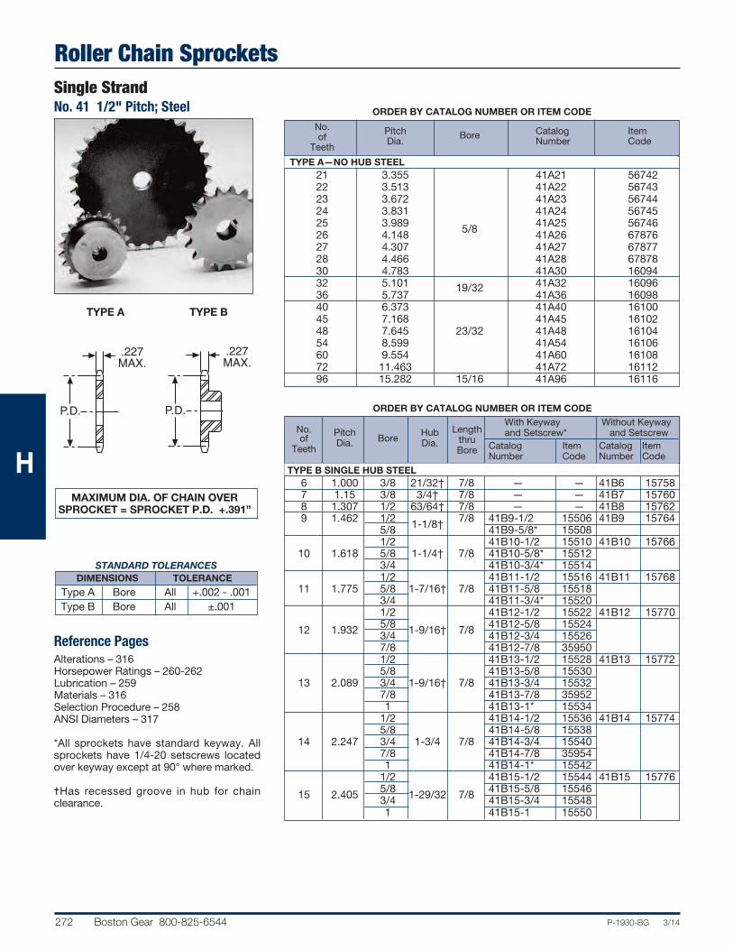
Roller Chain SprocketsSingle StrandNo. 41 1/2" Pitch; Steel
272 Boston Gear 800-825-6544 P-1930-BG 3/14
ORDER BY CATALOG NUMBER OR ITEM CODE
No.
Length
With Keyway Without Keyway
and Setscrew* and Setscrew
of
Pitch Hub
thru Catalog Item Catalog Item Teeth
Dia. Bore Dia. Bore Number Code Number Code
TYPE B SINGLE HUB STEEL 6 1.000 3/8 21/32† 7/8 — — 41B6 15758 7 1.15 3/8 3/4† 7/8 — — 41B7 15760 8 1.307 1/2 63/64† 7/8 — — 41B8 15762 9 1.462 1/2 1-1/8† 7/8 41B9-1/2 15506 41B9 15764 5/8 41B9-5/8* 15508 1/2 41B10-1/2 15510 41B10 15766 10 1.618 5/8 1-1/4† 7/8 41B10-5/8* 15512 3/4 41B10-3/4* 15514 1/2 41B11-1/2 15516 41B11 15768 11 1.775 5/8 1-7/16† 7/8 41B11-5/8 15518 3/4 41B11-3/4* 15520 1/2 41B12-1/2 15522 41B12 15770 12 1.932 5/8 1-9/16† 7/8 41B12-5/8 15524 3/4 41B12-3/4 15526 7/8 41B12-7/8 35950 1/2 41B13-1/2 15528 41B13 15772 5/8 41B13-5/8 15530 13 2.089 3/4 1-9/16† 7/8 41B13-3/4 15532 7/8 41B13-7/8 35952 1 41B13-1* 15534 1/2 41B14-1/2 15536 41B14 15774 5/8 41B14-5/8 15538 14 2.247 3/4 1-3/4 7/8 41B14-3/4 15540 7/8 41B14-7/8 35954 1 41B14-1* 15542 1/2 41B15-1/2 15544 41B15 15776 15 2.405 5/8 1-29/32 7/8 41B15-5/8 15546 3/4 41B15-3/4 15548 1 41B15-1 15550
ORDER BY CATALOG NUMBER OR ITEM CODE
No. of
Pitch Catalog Item
Teeth Dia.
Bore Number Code
TYPE A—NO HUB STEEL 21 3.355 41A21 56742 22 3.513 41A22 56743 23 3.672 41A23 56744 24 3.831 41A24 56745 25 3.989 41A25 56746 26 4.148 5/8 41A26 67876 27 4.307 41A27 67877 28 4.466 41A28 67878 30 4.783 41A30 16094 32 5.101 19/32 41A32 16096 36 5.737 41A36 16098 40 6.373 41A40 16100 45 7.168 41A45 16102 48 7.645 23/32 41A48 16104 54 8.599 41A54 16106 60 9.554 41A60 16108 72 11.463 41A72 16112 96 15.282 15/16 41A96 16116
STANDARD TOLERANCESDIMENSIONS TOLERANCE
Type A Bore All +.002 - .001 Type B Bore All ±.001
Reference PagesAlterations – 316Horsepower Ratings – 260-262Lubrication – 259Materials – 316Selection Procedure – 258ANSI Diameters – 317
*All sprockets have standard keyway. Allsprockets have 1/4-20 setscrews locatedover keyway except at 90° where marked.
=Has recessed groove in hub for chainclearance.
MAXIMUM DIA. OF CHAIN OVERSPROCKET = SPROCKET P.D. +.391”
P.D.
.227MAX.
P.D.
.227MAX.
TYPE A TYPE B
H

Roller Chain SprocketsSingle Strand
No. 41 1/2" Pitch; Steel
P-1930-BG 3/14 Boston Gear 800-825-6544 273
P.D.
.227MAX.
ORDER BY CATALOG NUMBER OR ITEM CODE
No.
Length
With Keyway Without Keyway
and Setscrew* and Setscrew
of
Pitch Hub
thru Catalog Item Catalog Item
Teeth Dia. Bore Dia.
Bore Number Code Number Code
TYPE B SINGLE HUB STEEL 5/8 41B16-5/8 15552 41B16 15778 16 2.563 3/4 2-1/16 7/8 41B16-3/4 15554 1 41B16-1 15556 5/8 41B17-5/8 15558 41B17 15780 17 2.721 3/4 2-15/64 1 41B17-3/4 15560 1 41B17-1 15562 5/8 41B18-5/8 15564 41B18 15782 18 2.879 3/4 2-3/8 1 41B18-3/4 15566 1 41B18-1 15568 5/8 41B19-5/8 35956 41B19 15784 19 3.038 3/4 2-15/32 1 41B19-3/4 15570 1 41B19-1 15572 5/8 41B20-5/8 35958 41B20 15786 20 3.196 3/4 2-3/4 1 41B20-3/4 15574 1 41B20-1 15576 5/8 41B21-5/8 35960 41B21 15788 21 3.355 3/4 2-7/8 1 41B21-3/4 15578 1 41B21-1 15580 5/8 41B22-5/8 35962 41B22 15790 22 3.513 3/4 3 1 41B22-3/4 15582 1 41B22-1 15584 5/8 41B23-5/8 35964 41B23 15792 23 3.672 3/4 3-3/16 1 41B23-3/4 15586 1 41B23-1 15588 5/8 41B24-5/8 35966 41B24 15794 24 3.831 3/4 3-1/4 1 41B24-3/4 15590 1 41B24-1 15592 5/8 41B25-5/8 35968 41B25 15796 25 3.989 3/4 3-1/4 1 41B25-3/4 15594 1 41B25-1 15596 5/8 41B26-5/8 68281 41B26 67920 26 4.148 3/4 3-1/4 1 41B26-3/4 68282 1 41B26-1 68283 5/8 41B27-5/8 68284 41B27 67930 27 4.307 3/4 3-1/4 1 41B27-3/4 68285 1 41B27-1 68286 5/8 41B28-5/8 68287 41B28 67931 28 4.466 3/4 3-1/4 1 41B28-3/4 68288 1 41B28-1 68289 5/8 41B30-5/8 68290 41B30 16464 30 4.783 3/4 3-1/4 1 41B30-3/4 68291 1 41B30-1 68292 32 5.101 5/8 3-1/4 1 — — 41B32 16466 36 5.737 5/8 3-1/4 1 — — 41B36 16468 40 6.373 3/4 3-1/4 1-1/16 — — 41B40 16470 45 7.168 3/4 3-1/2 1-1/16 — — 41B45 16472 48 7.645 3/4 3-1/2 1-1/16 — — 41B48 16474 54 8.599 3/4 3-1/2 1-1/16 — — 41B54 16476 60 9.554 3/4 3-1/2 1-1/16 — — 41B60 16478 72 11.463 3/4 4 1-3/16 — — 41B72 16482 96 15.282 1 4 1-3/16 — — 41B96 16486
STANDARD TOLERANCES
DIMENSION TOLERANCE
Bore All ±.001
Reference PagesAlterations – 316Horsepower Ratings – 260-262Lubrication – 259Materials – 316Selection Procedure – 258ANSI Diameters – 317
*All sprockets have standard keyways. Allsprockets have 1/4-20 setscrews locatedover keyway.
MAXIMUM DIA. OF CHAIN OVERSPROCKET = SPROCKET P.D. +.391”
H

Roller Chain SprocketsSingle StrandNo. 40 1/2" Pitch; Steel
274 Boston Gear 800-825-6544 P-1930-BG 3/14
ORDER BY CATALOG NUMBER OR ITEM CODE
No.
Length
With Keyway Without Keyway
and Setscrew* and Setscrew
of
Pitch Hub
thru Catalog Item Catalog Item Teeth
Dia. Bore Dia. Bore Number Code Number Code
TYPE B SINGLE HUB STEEL 8 1.307 1/2 31/32† 7/8 — — 40B8 15682 9 1.462 1/2 1-1/16† 7/8 40B9-1/2* 14980 40B9 15684 5/8 40B9-5/8* 14982 1/2 40B10-1/2 14984 40B10 15686 10 1.618 5/8 1-1/4† 7/8 40B10-5/8* 14986 3/4 40B10-3/4* 14988 1/2 40B11-1/2 36054 40B11 15688
11 1.775 5/8
1-3/8† 7/8 40B11-5/8 14990
3/4 40B11-3/4 14992 7/8 40B11-7/8* 14994 1/2 40B12-1/2 36056 40B12 15690 5/8 40B12-5/8 14996 12 1.932 3/4 1-9/16† 7/8 40B12-3/4 14998 7/8 40B12-7/8 15000 1 40B12-1* 15002 1/2 40B13-1/2 36058 40B13 15692 5/8 40B13-5/8 15004 13 2.089 3/4 1-9/16 7/8 40B13-3/4 15006 7/8 40B13-7/8 15008 1 40B13-1* 15010 1/2 40B14-1/2 36060 40B14 15694 5/8 40B14-5/8 15012 14 2.247 3/4 1-11/16 7/8 40B14-3/4 15014 7/8 40B14-7/8 15016 1 40B14-1 15018 1-1/8 40B14-1-1/8* 56732 1/2 40B15-1/2 36062 40B15 15696 5/8 40B15-5/8 15020 3/4 40B15-3/4 15022 15 2.405 7/8 1-13/16 7/8 40B15-7/8 15024 1 40B15-1 15026 1-1/8 40B15-1-1/8 15028 1-3/16 40B15-1-3/16* 15030 1-1/4 40B15-1-1/4* 15032
ORDER BY CATALOG NUMBER OR ITEM CODE
No. of
Pitch Catalog Item
Teeth Dia. Bore Number Code
TYPE A—NO HUB STEEL 19 3.038 40A19 68007 20 3.196 40A20 68008 21 3.355 40A21 56747 22 3.513 40A22 56748 23 3.672 5/8 40A23 56749 24 3.831 40A24 56750 25 3.989 40A25 56751 26 4.148 40A26 67014 27 4.307 40A27 67015 28 4.466 40A28 67016 30 4.783 40A30 16258 32 5.101 40A32 16260 35 5.578 19/32 40A35 68023 36 5.737 40A36 16262 38 6.055 40A38 68026 40 6.373 40A40 16264 42 6.691 40A42 16266 45 7.168 40A45 16268 48 7.645 23/32 40A48 16270 54 8.599 40A54 16272 60 9.554 40A60 16274 72 11.463 40A72 16278 84 13.372 40A84 16282 96 15.282 15/16 40A96 16284 112 17.828 40A112 16286
Reference PagesAlterations –316Horsepower Ratings – 260-262Lubrication – 259Materials – 316Selection Procedure – 258ANSI Diameters – 317
*All sprockets have standard keyways.All sprockets have 1/4-20 setscrews,located over keyway, except at 90°where marked.
=Has recessed groove in the hub forchain clearance.
MAXIMUM DIA. OF CHAIN OVERSPROCKET = SPROCKET P.D. +.469”
STANDARD TOLERANCESDIMENSIONS TOLERANCE
Type A Bore All +.002 - .001 Type B Bore All ±.001
P.D.
.284MAX.
P.D.
.284MAX.
TYPE A TYPE B
H

Roller Chain SprocketsSingle Strand
No. 40 1/2" Pitch; Steel
P-1930-BG 3/14 Boston Gear 800-825-6544 275
ORDER BY CATALOG NUMBER OR ITEM CODE
No.
Length
With Keyway Without Keyway
and Setscrew* and Setscrew
of
Pitch Hub
thru Catalog Item Catalog Item
Teeth Dia. Bore Dia.
Bore Number Code Number Code
TYPE B SINGLE HUB STEEL 5/8 40B16-5/8 15034 40B16 15698 3/4 40B16-3/4 15036 7/8 40B16-7/8 15038 16 2.563 1 2 7/8 40B16-1 15040 1-1/8 40B16-1-1/8 36064 1-3/16 40B16-1-3/16 15042 1-1/4 40B16-1-1/4 15044 5/8 40B17-5/8 15046 40B17 15700 3/4 40B17-3/4 15048 7/8 40B17-7/8 36066 17 2.721 1 2-1/8 1 40B17-1 15050 1-1/8 40B17-1-1/8 15052 1-3/16 40B17-1-3/16 15054 1-1/4 40B17-1-1/4 56733 5/8 40B18-5/8 36068 40B18 15702 3/4 40B18-3/4 15056 7/8 40B18-7/8 15058 1 40B18-1 15060 18 2.879 1-1/8 2-5/16 1 40B18-1-1/8 15062 1-3/16 40B18-1-3/16 15064 1-1/4 40B18-1-1/4 15066 1-3/8 40B18-1-3/8 36070 1-7/16 40B18-1-7/16 15068 1-1/2 40B18-1-1/2 15070 5/8 40B19-5/8 36072 40B19 15704 3/4 40B19-3/4 15072 7/8 40B19-7/8 36074 1 40B19-1 15074 19 3.038 1-1/8 2-1/2 1 40B19-1-1/8 36076 1-3/16 40B19-1-3/16 15076 1-1/4 40B19-1-1/4 36078 1-3/8 40B19-1-3/8 36080 1-7/16 40B19-1-7/16* 15078 1-1/2 40B19-1-1/2* 56734 5/8 40B20-5/8 36082 40B20 15706 3/4 40B20-3/4 15080 7/8 40B20-7/8 15082 1 40B20-1 15084 20 3.196 1-1/8 2-5/8 1 40B20-1-1/8 15086 1-3/16 40B20-1-3/16 15088 1-1/4 40B20-1-1/4 15090 1-3/8 40B20-1-3/8 36084 1-7/16 40B20-1-7/16 15092 1-1/2 40B20-1-1/2 15094 5/8 40B21-5/8 36086 40B21 15708 3/4 40B21-3/4 17148 7/8 40B21-7/8 15096 1 40B21-1 15098 21 3.355 1-1/8 2-3/4 1 40B21-1-1/8 36088 1-3/16 40B21-1-3/16 15100 1-1/4 40B21-1-1/4 36090 1-3/8 40B21-1-3/8 36092 1-7/16 40B21-1-7/16* 15102 1-1/2 40B21-1-1/2* 15104
P.D.
.284MAX.
Reference PagesAlterations – 316Horsepower Ratings – 260-262Lubrication – 259Materials – 316Selection Procedure – 258ANSI Diameters – 317
*All sprockets have standard keyways.Sprockets 16-17 teeth have 1/4-20setscrews, 18-21 teeth 5/16-18setscrews, located over keyway, exceptat 90° where marked.
MAXIMUM DIA. OF CHAIN OVERSPROCKET = SPROCKET P.D. +.469”
H
STANDARD TOLERANCES
DIMENSION TOLERANCE
Bore All ±.001
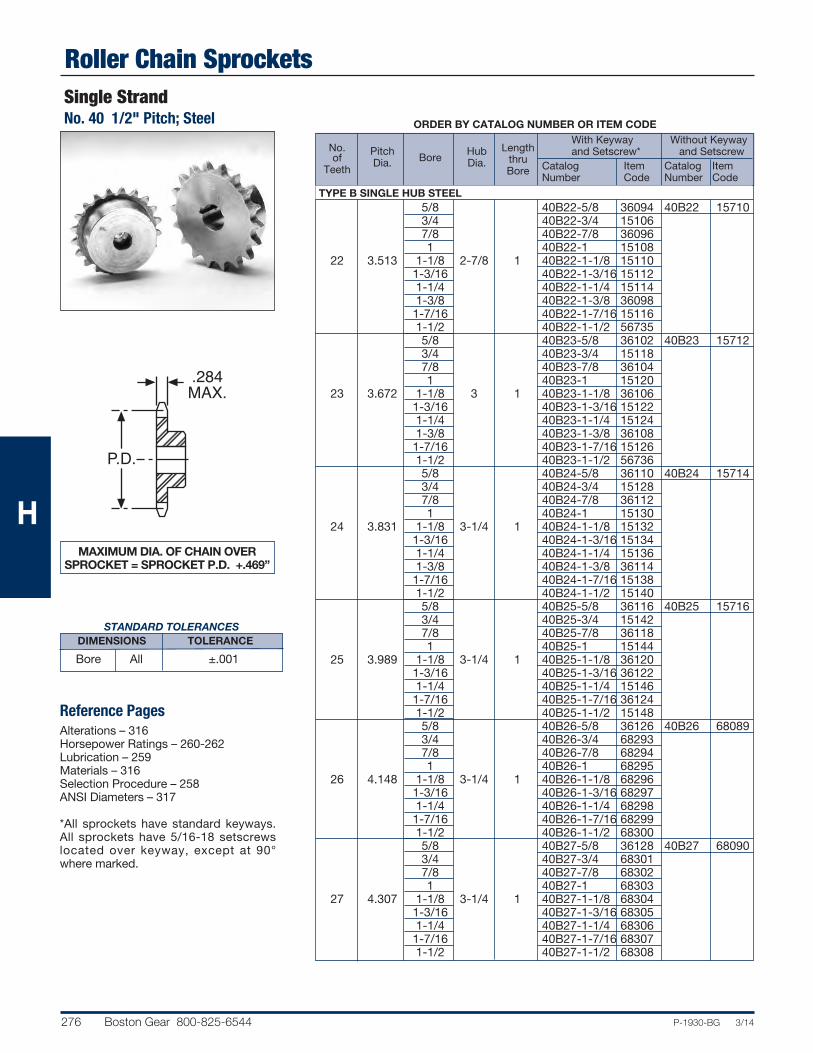
Roller Chain SprocketsSingle StrandNo. 40 1/2" Pitch; Steel
276 Boston Gear 800-825-6544 P-1930-BG 3/14
ORDER BY CATALOG NUMBER OR ITEM CODE
No.
Length
With Keyway Without Keyway
and Setscrew* and Setscrew
of
Pitch Hub
thru Catalog Item Catalog Item Teeth
Dia. Bore Dia. Bore Number Code Number Code
TYPE B SINGLE HUB STEEL 5/8 40B22-5/8 36094 40B22 15710 3/4 40B22-3/4 15106 7/8 40B22-7/8 36096 1 40B22-1 15108 22 3.513 1-1/8 2-7/8 1 40B22-1-1/8 15110 1-3/16 40B22-1-3/16 15112 1-1/4 40B22-1-1/4 15114 1-3/8 40B22-1-3/8 36098 1-7/16 40B22-1-7/16 15116 1-1/2 40B22-1-1/2 56735 5/8 40B23-5/8 36102 40B23 15712 3/4 40B23-3/4 15118 7/8 40B23-7/8 36104 1 40B23-1 15120 23 3.672 1-1/8 3 1 40B23-1-1/8 36106 1-3/16 40B23-1-3/16 15122 1-1/4 40B23-1-1/4 15124 1-3/8 40B23-1-3/8 36108 1-7/16 40B23-1-7/16 15126 1-1/2 40B23-1-1/2 56736 5/8 40B24-5/8 36110 40B24 15714 3/4 40B24-3/4 15128 7/8 40B24-7/8 36112 1 40B24-1 15130 24 3.831 1-1/8 3-1/4 1 40B24-1-1/8 15132 1-3/16 40B24-1-3/16 15134 1-1/4 40B24-1-1/4 15136 1-3/8 40B24-1-3/8 36114 1-7/16 40B24-1-7/16 15138 1-1/2 40B24-1-1/2 15140 5/8 40B25-5/8 36116 40B25 15716 3/4 40B25-3/4 15142 7/8 40B25-7/8 36118 1 40B25-1 15144 25 3.989 1-1/8 3-1/4 1 40B25-1-1/8 36120 1-3/16 40B25-1-3/16 36122 1-1/4 40B25-1-1/4 15146 1-7/16 40B25-1-7/16 36124 1-1/2 40B25-1-1/2 15148 5/8 40B26-5/8 36126 40B26 68089 3/4 40B26-3/4 68293 7/8 40B26-7/8 68294 1 40B26-1 68295 26 4.148 1-1/8 3-1/4 1 40B26-1-1/8 68296 1-3/16 40B26-1-3/16 68297 1-1/4 40B26-1-1/4 68298 1-7/16 40B26-1-7/16 68299 1-1/2 40B26-1-1/2 68300 5/8 40B27-5/8 36128 40B27 68090 3/4 40B27-3/4 68301 7/8 40B27-7/8 68302 1 40B27-1 68303 27 4.307 1-1/8 3-1/4 1 40B27-1-1/8 68304 1-3/16 40B27-1-3/16 68305 1-1/4 40B27-1-1/4 68306 1-7/16 40B27-1-7/16 68307 1-1/2 40B27-1-1/2 68308
P.D.
.284MAX.
STANDARD TOLERANCESDIMENSIONS TOLERANCE
Bore All ±.001
Reference PagesAlterations – 316Horsepower Ratings – 260-262Lubrication – 259Materials – 316Selection Procedure – 258ANSI Diameters – 317
*All sprockets have standard keyways.All sprockets have 5/16-18 setscrewslocated over keyway, except at 90°where marked.
MAXIMUM DIA. OF CHAIN OVERSPROCKET = SPROCKET P.D. +.469”
H

Roller Chain SprocketsSingle Strand
No. 40 1/2" Pitch; Steel
P-1930-BG 3/14 Boston Gear 800-825-6544 277
ORDER BY CATALOG NUMBER OR ITEM CODE
P.D.
.284MAX.
Reference PagesAlterations – 316Horsepower Ratings – 260-262Lubrication – 259Materials – 316Selection Procedure – 258ANSI Diameters – 317
*All sprockets have standard keyways.All sprockets have 5/16-18 setscrewslocated over keyway.
MAXIMUM DIA. OF CHAIN OVERSPROCKET = SPROCKET P.D. +.469”
No.
Length
With Keyway Without Keyway
and Setscrew* and Setscrew
of
Pitch Hub
thru Catalog Item Catalog Item
Teeth Dia. Bore Dia.
Bore Number Code Number Code
TYPE B SINGLE HUB STEEL 5/8 40B28-5/8 36130 40B28 68091 3/4 40B28-3/4 68309 7/8 40B28-7/8 68310 1 40B28-1 68311 28 4.466 1-1/8 3-1/4 1 40B28-1-1/8 68312 1-3/16 40B28-1-3/16 68313 1-1/4 40B28-1-1/4 68314 1-7/16 40B28-1-7/16 68315 1-1/2 40B28-1-1/2 68316 5/8 40B30-5/8 36134 40B30 16434 3/4 40B30-3/4 68325 7/8 40B30-7/8 68326 1 40B30-1 68327 30 4.783 1-1/8 3-1/4 1 40B30-1-1/8 68328 1-3/16 40B30-1-3/16 68329 1-1/4 40B30-1-1/4 68330 1-7/16 40B30-1-7/16 68331 1-1/2 40B30-1-1/2 68332 32 5.101 5/8 3-1/4 1 — — 40B32 16436 5/8 40B35-5/8 36186 40B35 68096 3/4 40B35-3/4 36188 1 40B35-1 36190 35 5.578 1-1/4 3-1/4 1 40B35-1-1/4 36192 1-7/16 40B35-1-7/16 36194 1-1/2 40B35-1-1/2 36196 3/4 40B36-3/4 49478 40B36 16438 1 40B36-1 36200 36 5.738 1-1/4 3-1/4 1 40B36-1-1/4 45979 1-7/16 40B36-1-7/16 45980 1-1/2 40B36-1-1/2 45981 38 6.055 5/8 3-1/4 1 — — 40B38 68098 40 6.373 3/4 3-1/2 1-1/8 — — 40B40 16440 3/4 40B42-3/4 49479 40B42 16442 1 40B42-1 36264 42 6.691 1-1/4 3-1/2 1-1/8 40B42-1-1/4 36266 1-7/16 40B42-1-7/16 36268 1-1/2 40B42-1-1/2 36270 3/4 40B45-3/4 49480 40B45 16444 1 40B45-1 36298 45 7.168 1-1/4 3-1/2 1-1/8 40B45-1-1/4 36300 1-7/16 40B45-1-7/16 36302 1-1/2 40B45-1-1/2 36304 3/4 40B48-3/4 49481 40B48 16446 1 40B48-1 36330 48 7.645 1-1/4 3-1/2 1-1/8 40B48-1-1/4 36332 1-7/16 40B48-1-7/16 36334 1-1/2 40B48-1-1/2 36336 54 8.599 3/4 3-1/2 1-1/8 — — 40B54 16448 1 40B60-1 36470 40B60 16450
60 9.554 1-1/4
3-1/2 1-1/8 40B60-1-1/4 36472
1-7/16 40B60-1-7/16 36474 1-1/2 40B60-1-1/2 36476 72 11.463 3/4 4 1-1/4 — — 40B72 16454 84 13.372 3/4 4 1-1/4 — — 40B84 16458 96 15.282 1 4 1-1/4 — — 40B96 16460 112 17.828 1 4 1-1/4 — — 40B112 16462
H
STANDARD TOLERANCES
DIMENSION TOLERANCE
Bore All ±.001

Roller Chain SprocketsSingle StrandNo. 40 1/2" Pitch; Stainless Steel
278 Boston Gear 800-825-6544 P-1930-BG 3/14
Double StrandNo. 40 2-1/2" Pitch; Steel
P.D.
.284MAX.
Reference PagesAlterations – 316Horsepower Ratings – 260-262Lubrication – 259Materials – 316Selection Procedure – 258ANSI Diameters – 317
MAXIMUM DIA. OF CHAIN OVERSPROCKET = SPROCKET P.D. +.469”
ORDER BY CATALOG NUMBER OR ITEM CODE
Without Keyway
No. or Setscrew
of Pitch Bore Hub Length
Catalog Item
Teeth Dia. Dia. thru Number Code
TYPE B SINGLE HUB STEEL 13 2.089 1-1/2 D40B13 46563 14 2.247 1/2 1-11/16 1-1/2 D40B14 46564 15 2.405 1-13/126 D40B15 46565 16 2.563 2 D40B16 15950 17 2.721 1/2 2-1/8 1-1/2 D40B17 15952 18 2.879 2-5/16 D40B18 15954 19 3.038 2-1/2 D40B19 15956 20 3.196 2-5/8 D40B20 15958 21 3.355 2-3/4 D40B21 15960 22 3.513 5/8 2-7/8 1-5/8 D40B22 15962 23 3.672 3 D40B23 15964 24 3.831 3-1/4 D40B24 15966 25 4.989 3-1/4 D40B25 15968 26 4.148 3-1/4 D40B26 68011 30 4.783 7/8 2-1/2 1-5/8 D40B30 68012 35 5.578 3-1/4 D40B35 68013 36 5.737 15/16 3-3/4 1-5/8 D40B36 68018 40 6.373 3-3/4 1-3/4 D40B40 68020P.D.
.841
.275MAX
.395
ORDER BY CATALOG NUMBER OR ITEM CODE
Without Keyway
No. or Setscrew
of Pitch Bore Hub Length
Catalog Item
Teeth Dia. Dia. thru Number Code
TYPE B SINGLE HUB STAINLESS STEEL 10 1.618 1-1/4† 40B10SS 69275 11 1.775 1-3/8† 40B11SS 69276 12 1.932 1/2 1-9/16† 7/8 40B12SS 69277 13 2.089 1-9/16 40B13SS 69278 14 2.247 1-11/16 40B14SS 69279 15 2.405 5/8 1-13/16 7/8 40B15SS 69280 16 2.563 2 40B16SS 69281 17 2.721 2-1/8 40B17SS 69282 18 2.879 2-5/16 40B18SS 69283 19 3.038 2-1/2 40B19SS 69294 20 3.196 5/8 2-5/8 1 40B20SS 69295 25 3.989 3-1/4 40B25SS 69296 30 4.783 3-1/4 40B30SS 69297 40 6.373 3-1/2 40B40SS 69300 45 7.168 3/4 3-1/2 1 40B45SS 69301 60 9.554 3-1/2 40B60SS 69302
†Has recessed groove in hub for chain reference.
STANDARD TOLERANCESDIMENSIONS TOLERANCE
Stainless Steel Bore All +.002 —.000Double StrandBore All ±,001
H

Roller Chain SprocketsSingle Strand
No. 50 5/8" Pitch; Steel
P-1930-BG 3/14 Boston Gear 800-825-6544 279
ORDER BY CATALOG NUMBER OR ITEM CODE
With Keyway Without Keyway
No. Pitch Hub
Length & Setscrew* or Setscrew
of
Dia. Bore
Dia. thru
Catalog Item Catalog Item
Teeth
Bore Number Code Number Code
TYPE B SINGLE HUB STEEL
8 1.633 5/8 1-1/8† 1 50B8-5/8* 49482 50B8 15798
9 1.827 5/8
1-3/8† 1 50B9-5/8 15150 50B9 15800
3/4 50B9-3/4* 15152 5/8 50B10-5/8 15154 50B10 15802
10 2.023 3/4
1-9/16† 1 50B10-3/4 15156
7/8 50B10-7/8 36496 1 50B10-1* 36498 5/8 50B11-5/8 15158 50B11 15804
11 2.218 3/4
1-3/4† 1 50B11-3/4 15160
7/8 50B11-7/8 15162 1 50B11-1* 15164 5/8 50B12-5/8 15166 50B12 15806 3/4 50B12-3/4 15168 7/8 50B12-7/8 15170 12 2.415 1 1-63/64† 1 50B12-1 15172 1-1/8 50B12-1-1/8 15174 1-3/16 50B12-1-3/16 36500 1-1/4 50B12-1-1/4* 36502 5/8 50B13-5/8 36504 50B13 15808 3/4 50B13-3/4 15176 7/8 50B13-7/8 15178 13 2.612 1 1-7/8 1 50B13-1 15180 1-1/8 50B13-1-1/8* 15182 1-3/16 50B13-1-3/16 15184 1-1/4 50B13-1-1/4* 15186 5/8 50B14-5/8 36506 50B14 15810 3/4 50B14-3/4 15188 7/8 50B14-7/8 15190 14 2.809 1 2-1/8 1 50B14-1 15192 1-1/8 50B14-1-1/8 15194 1-3/16 50B14-1-3/16 15196 1-1/4 50B14-1-1/4* 15198
MAXIMUM DIA. OF CHAIN OVERSPROCKET = SPROCKET P.D. + .594”
Reference PagesAlterations – 316Horsepower Ratings – 260-262Lubrication – 259Materials – 316Selection Procedure – 258ANSI Diameters – 317
*All sprockets have standard keyway.Sprockets 8-12 teeth have 1/4–20setscrew, 13-14 teeth 5/16-18 setscrewlocated over keyway except at 90° wheremarked.
†Has recessed groove in hub for chainclearance.
ORDER BY CATALOG NUMBER OR ITEM CODE
No. of
Pitch Bore
Catalog Item
Teeth Dia.
Number Code
TYPE A NO HUB STEEL 17 3.401 50A17 45865 18 3.599 5/8 50A18 56752 19 3.797 50A19 56753 20 3.955 50A20 56754 21 4.193 3/4 50A21 56755 22 4.392 50A22 56756 23 4.590 50A23 56757 24 4.788 50A24 56758 25 4.987 50A25 16288 26 5.185 50A26 45866 28 5.582 50A28 45867 30 5.979 50A30 16290 32 6.376 23/32 50A32 16292 35 6.872 50A35 45872 36 7.171 50A36 16294 40 7.966 50A40 16296 42 8.363 50A42 16298 45 8.960 50A45 16300 48 9.556 50A48 16302 54 10.749 50A54 16304 60 11.942 50A60 16306 72 14.328 15/16 50A72 16310 84 16.715 50A84 16314 96 19.102 50A96 16316 112 21.885 50A112 16318
P.D.
.343MAX.
P.D.
.343MAX.
TYPE A TYPE B
H
STANDARD TOLERANCES
DIMENSION TOLERANCE Type A Bore All +.002 - .001
Type B Bore All ±.001

Roller Chain SprocketsSingle StrandNo. 50 5/8" Pitch; Steel
280 Boston Gear 800-825-6544 P-1930-BG 3/14
STANDARD TOLERANCES DIMENSIONS TOLERANCE
Bore All ±.001
P.D.
.343MAX.
ORDER BY CATALOG NUMBER OR ITEM CODE
With Keyway Without Keyway
No. Pitch Hub
Length & Setscrew* or Setscrew
of
Dia. Bore
Dia. thru
Catalog Item Catalog Item Teeth
Bore
Number Code Number CodeTYPE B SINGLE HUB STEEL
5/8 50B15-5/8 36508 50B15 15812 3/4 50B15-3/4 15200 7/8 50B15-7/8 15202 1 50B15-1 15204 15 3.006 1-1/8 2-3/8 1 50B15-1-1/8 36206 1-3/16 50B15-1-3/16 15208 1-1/4 50B15-1-1/4 15210 1-3/8 50B15-1-3/8 15212 1-7/16 50B15-1-7/16* 15214 1-1/2 50B15-1-1/2* 36510 5/8 50B16-5/8 36512 50B16 15814 3/4 50B16-3/4 15216 7/8 50B16-7/8 15218 1 50B16-1 15220 1-1/8 50B16-1-1/8 15222 16 3.204 1-3/16 2-1/2 1 50B16-1-3/16 15224 1-1/4 50B16-1-1/4 15226 1-3/8 50B16-1-3/8 15228 1-7/16 50B16-1-7/16 15230 1-1/2 50B16-1-1/2* 15232 1-5/8 50B16-1-5/8* 36514 5/8 50B17-5/8 36516 50B17 15816 3/4 50B17-3/4 15234 7/8 50B17-7/8 17150 1 50B17-1 15236 1-1/8 50B17-1-1/8 15238 17 3.401 1-3/16 2-11/16 1 50B17-1-3/16 15240 1-1/4 50B17-1-1/4 15242 1-3/8 50B17-1-3/8* 15244 1-7/16 50B17-1-7/16* 15246 1-1/2 50B17-1-1/2* 56737 1-5/8 50B17-1-5/8* 36518 5/8 50B18-5/8 36520 50B18 15818 3/4 50B18-3/4 15248 7/8 50B18-7/8 15250 1 50B18-1 15252 18 3.599 1-1/8 2-7/8 1 50B18-1-1/8 36522 1-3/16 50B18-1-3/16 15254 1-1/4 50B18-1-1/4 15256 1-3/8 50B18-1-1/4 15258 1-7/16 50B18-1-7/16 15260 1-1/2 50B18-1-1/2 15262 5/8 50B19-5/8 36524 50B19 15820 3/4 50B19-3/4 36526 7/8 50B19-7/8 36528 1 50B19-1 15264 19 3.797 1-1/8 3 1 50B19-1-1/8 15266 1-3/16 50B19-1-3/16 15268 1-1/4 50B19-1-1/4 15270 1-3/8 50B19-1-1/4 15272 1-7/16 50B19-1-7/16 15274 1-1/2 50B19-1-1/2 15276 3/4 50B20-3/4 36530 50B20 15833 7/8 50B20-7/8 15278 1 50B20-1 15280
20 3.995 1-1/8
3 1 50B20-1-1/8 56738
1-3/16 50B20-1-3/16 15282 1-1/4 50B20-1-1/4 15284 1-3/8 50B20-1-1/4 15286 1-7/16 50B20-1-7/16 15288 1-1/2 50B20-1-1/2 15290 1-5/8 50B20-1-5/8 36532
MAXIMUM DIA. OF CHAIN OVERSPROCKET = SPROCKET P.D. + .594”
Reference PagesAlterations – 316Horsepower Ratings – 260-262Lubrication – 259Materials – 316Selection Procedure – 258ANSI Diameters – 317
*All sprockets have standard keyway. Allsprockets have 5/16–18 setscrews located over keyway except at 90° wheremarked.
H
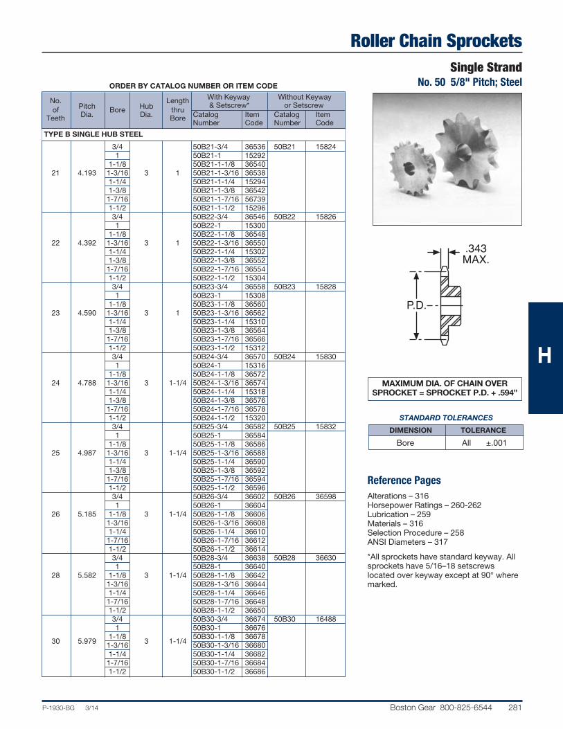
Roller Chain SprocketsSingle Strand
No. 50 5/8" Pitch; Steel
P-1930-BG 3/14 Boston Gear 800-825-6544 281
P.D.
.343MAX.
ORDER BY CATALOG NUMBER OR ITEM CODE
With Keyway Without Keyway
No. Pitch Hub
Length & Setscrew* or Setscrew
of
Dia. Bore
Dia. thru
Catalog Item Catalog Item
Teeth
Bore Number Code Number Code
TYPE B SINGLE HUB STEEL
3/4 50B21-3/4 36536 50B21 15824 1 50B21-1 15292 1-1/8 50B21-1-1/8 36540 21 4.193 1-3/16 3 1 50B21-1-3/16 36538 1-1/4 50B21-1-1/4 15294 1-3/8 50B21-1-3/8 36542 1-7/16 50B21-1-7/16 56739 1-1/2 50B21-1-1/2 15296 3/4 50B22-3/4 36546 50B22 15826 1 50B22-1 15300 1-1/8 50B22-1-1/8 36548 22 4.392 1-3/16 3 1 50B22-1-3/16 36550 1-1/4 50B22-1-1/4 15302 1-3/8 50B22-1-3/8 36552 1-7/16 50B22-1-7/16 36554 1-1/2 50B22-1-1/2 15304 3/4 50B23-3/4 36558 50B23 15828 1 50B23-1 15308 1-1/8 50B23-1-1/8 36560 23 4.590 1-3/16 3 1 50B23-1-3/16 36562 1-1/4 50B23-1-1/4 15310 1-3/8 50B23-1-3/8 36564 1-7/16 50B23-1-7/16 36566 1-1/2 50B23-1-1/2 15312 3/4 50B24-3/4 36570 50B24 15830 1 50B24-1 15316 1-1/8 50B24-1-1/8 36572 24 4.788 1-3/16 3 1-1/4 50B24-1-3/16 36574 1-1/4 50B24-1-1/4 15318 1-3/8 50B24-1-3/8 36576 1-7/16 50B24-1-7/16 36578 1-1/2 50B24-1-1/2 15320 3/4 50B25-3/4 36582 50B25 15832 1 50B25-1 36584 1-1/8 50B25-1-1/8 36586 25 4.987 1-3/16 3 1-1/4 50B25-1-3/16 36588 1-1/4 50B25-1-1/4 36590 1-3/8 50B25-1-3/8 36592 1-7/16 50B25-1-7/16 36594 1-1/2 50B25-1-1/2 36596 3/4 50B26-3/4 36602 50B26 36598 1 50B26-1 36604 26 5.185 1-1/8 3 1-1/4 50B26-1-1/8 36606 1-3/16 50B26-1-3/16 36608 1-1/4 50B26-1-1/4 36610 1-7/16 50B26-1-7/16 36612 1-1/2 50B26-1-1/2 36614 3/4 50B28-3/4 36638 50B28 36630 1 50B28-1 36640 28 5.582 1-1/8 3 1-1/4 50B28-1-1/8 36642 1-3/16 50B28-1-3/16 36644 1-1/4 50B28-1-1/4 36646 1-7/16 50B28-1-7/16 36648 1-1/2 50B28-1-1/2 36650 3/4 50B30-3/4 36674 50B30 16488 1 50B30-1 36676
30 5.979 1-1/8
3 1-1/4 50B30-1-1/8 36678
1-3/16 50B30-1-3/16 36680 1-1/4 50B30-1-1/4 36682 1-7/16 50B30-1-7/16 36684 1-1/2 50B30-1-1/2 36686
MAXIMUM DIA. OF CHAIN OVERSPROCKET = SPROCKET P.D. + .594”
Reference PagesAlterations – 316Horsepower Ratings – 260-262Lubrication – 259Materials – 316Selection Procedure – 258ANSI Diameters – 317
*All sprockets have standard keyway. Allsprockets have 5/16–18 setscrews located over keyway except at 90° wheremarked.
H
STANDARD TOLERANCES
DIMENSION TOLERANCE
Bore All ±.001

Roller Chain SprocketsSingle StrandNo. 50 5/8" Pitch; Steel
282 Boston Gear 800-825-6544 P-1930-BG 3/14
Double StrandNo. 50-2 5/8" Pitch; Steel
P.D.
.343MAX.
P.D.
1.045
.332MAX
.500
ORDER BY CATALOG NUMBER OR ITEM CODE
With Keyway Without Keyway
No. Pitch Hub
Length & Setscrew* or Setscrew
of
Dia. Bore
Dia. thru
Catalog Item Catalog Item Teeth
Bore
Number Code Number Code
TYPE B SINGLE HUB STEEL
32 6.376 3/4 3-1/4 1-1/4 — — 50B32 16490 — — — — — 3/4 50B35-3/4 36748 50B35 36744 35 6.972 1 3-1/4 1-1/4 50B35-1 36750 1-1/4 50B35-1-1/4 36752 1-7/16 50B35-1-7/16 36754 1-1/2 50B35-1-1/2 36756 36 7.171 3/4 3-1/4 1-1/4 — — 50B36 16490 3/4 50B40-3/4 36808 50B40 16494 1 50B40-1 36810 40 7.966 1-1/4 3-1/4 1-1/4 50B40-1-1/4 36812 1-7/16 50B40-1-7/16 36814 1-1/2 50B40-1-1/2 36816 1-15/16 50B40-1-15/16* 36818 42 8.363 3/4 3-1/4 1-1/4 — — 50B42 16496 3/4 50B45-3/4 36876 50B45 16498 1 50B45-1 36878 45 8.960 1-1/4 3-3/4 1-1/4 50B45-1-1/4 36880 1-7/16 50B45-1-7/16 36882 1-1/2 50B45-1-1/2 36884 1-15/16 50B45-1-15/16* 36886 1 50B48-1 36892 50B48 16500 48 9.556 1-1/4 3-3/4 1-1/4 50B48-1-1/4 36894 1-7/16 50B48-1-7/16 36896 1-1/2 50B48-1-1/2 36898 1-15/16 50B48-1-15/16* 35942 54 10.749 1 3-3/4 1-1/4 — — 50B54 16502 1 50B60-1 35920 50B60 16504 1-1/4
3-3/4 1-1/4 50B60-1-1/4 35922
60 11.942 1-7/16 50B60-1-7/16 35924 1-1/2 50B60-1-1/2 35926 1-15/16 50B60-1-15/16* 35928 72 14.328 1 3-3/4 1-3/4 — — 50B72 16508 84 16.715 1 4-1/4 1-3/4 — — 50B84 16512 96 19.102 1 4-1/4 1-3/4 — — 50B96 16514 112 21.885 1 4-1/4 1-3/4 — — 50B112 16516
Reference PagesAlterations – 316Horsepower Ratings – 260-262Lubrication – 259Materials – 316Selection Procedure – 258ANSI Diameters – 317*All sprockets have standard keyway. Allsprockets have 5/16–18 setscrews locatedover keyway except at 90° where marked.
STANDARD TOLERANCES DIMENSIONS TOLERANCE
Bore All ±.001
MAXIMUM DIA. OF CHAIN OVERSPROCKET = SPROCKET P.D. + .594”
ORDER BY CATALOG NUMBER OR ITEM CODE
With Keyway
No. Pitch Hub
Length & Setscrew*
of
Dia. Bore
Dia. thru
Catalog Item
Teeth
Bore Number Code
TYPE B SINGLE HUB STEEL
15 3.006 2-5/16 D50B15 15970 16 3.204 3/4 2-1/2 1-3/4 D50B16 15972 17 3.401 2-11/16 D50B17 15974 18 3.599 2-15/16 D50B18 15976 20 3/995 1 3-1/4 1-3/4 D50B20 15980 21 4.193 3-1/2 D50B21 15982 22 4.392 3-9/16 D50B22 15984 24 4.788 1 3-5/8 1-7/8 D50B24 15988 25 4.987 3-5/8 D50B25 15990 30 5.979 3-3/4 D50B30 68166 40 7.966 1-3/16 4 2-1/8 D50B40 68173
H

Roller Chain SprocketsSingle Strand
No. 60 3/4" Pitch; Steel
P-1930-BG 3/14 Boston Gear 800-825-6544 283
ORDER BY CATALOG NUMBER OR ITEM CODE
With Keyway Without Keyway
No. Pitch Hub
Length & Setscrew* or Setscrew
of
Dia. Bore
Dia. thru
Catalog Item Catalog Item
Teeth
Bore Number Code Number Code
TYPE B SINGLE HUB STEEL
8 1.960 5/8 1-15/32† 1-1/4 60B8-3/4* 49483 60B8 15834 9 2.193 3/4 1-9/16† 1-1/4 60B9-3/4* 15324 60B9 15836 3/4 60B10-3/4 15326 60B10 15838 7/8 60B10-7/8 36180 10 2.023 1 1-9/16† 1-1/4 60B10-1 15328 1-1/8 60B10-1-1/8* 36182 1-3/16 60B10-1-3/16* 36184 1-3/4 60B10-1-1/4* 36162 3/4 60B11-3/4 15334 60B11 15840 7/8 60B11-7/8 36164 11 2.662 1 2-1/16† 1-1/4 60B11-1 15332 1-1/8 60B11-1-1/8* 56740 1-3/16 60B11-1-3/16* 36494 1-3/4 60B11-1-1/4* 15330 3/4 60B12-3/4 15336 60B12 15842 7/8 60B12-7/8 36616 1 60B12-1 15338 12 2.898 1-1/8 2-3/8† 1-1/4 60B12-1-1/8 15340 1-3/16 60B12-1-3/16 15342 1-3/4 60B12-1-1/4 15344 1-7/16 60B12-1-7/16* 36618 3/4 60B13-3/4 15346 60B13 15844 7/8 60B13-7/8 36620 1 60B13-1 15348 1-1/8 60B13-1-1/8 15350 13 3.134 1-3/16 2-11/32 1-1/4 60B13-1-3/16 15352 1-1/4 60B13-1-1/4 15354 1-3/8 60B13-1-3/8 15356 1-7/16 60B13-1-7/16* 15358 1-1/2 60B13-1-1/2* 15360 3/4 60B14-3/4 15362 60B14 15846 7/8 60B14-7/8 36144 1 60B14-1 15364 1-1/8 60B14-1-1/8 36146 1-3/16 60B14-1-3/16 15366 14 3.370 1-1/4 2-9/16 1-1/4 60B14-1-1/4 15368 1-3/8 60B14-1-3/8 15370 1-7/16 60B14-1-7/16 15372 1-1/2 60B14-1-1/2 15374 1-9/16 60B14-1-9/16* 36148 1-5/8 60B14-1-5/8* 36150
MAXIMUM DIA. OF CHAIN OVERSPROCKET = SPROCKET P.D. + .703”
Reference PagesAlterations – 316Horsepower Ratings – 260-262Lubrication – 259Materials – 316Selection Procedure – 258ANSI Diameters – 317
*All sprockets have standard keyway. Allsprockets have 1/4–20 setscrew, 9 to 12tooth sprockets have 5/16–18 setscrewand 13 and 14 tooth sprockets have 3/8–16 setscrew, located over keyway exceptat 90° where marked.
†Has recessed groove in hub for chainclearance.
ORDER BY CATALOG NUMBER OR ITEM CODE
No. of Pitch Catalog Item Teeth Dia. Bore Number Code
TYPE A NO HUB STEEL 17 4.082 60A17 56759 18 4.319 60A18 56760 19 4.557 60A19 56761 20 4.794 3/4 60A20 56762 21 5.032 60A21 16320 22 5.270 60A22 16322 23 5.508 60A23 16324 24 5.746 60A24 16326 25 5.984 60A25 16328 26 6.222 23/32 60A26 61894 28 6.699 60A28 46466 30 7.175 60A30 16330 32 7.652 60A32 16332 35 8.367 60A35 46471 36 8.605 60A36 16334 40 9.559 15/16 60A40 16336 45 10.752 60A45 16340 48 11.467 60A48 16342 54 12.899 60A54 16344 60 14.330 1-1/4 60A60 16346 72 17.194 60A72 16350 P.D.
.575MAX.
P.D.
.459MAX.
TYPE A TYPE B
H
STANDARD TOLERANCES
DIMENSION TOLERANCE Type A Bore All +.002 - .001
Type B Bore All ±.001

Roller Chain SprocketsSingle StrandNo. 60 3/4" Pitch; Steel
284 Boston Gear 800-825-6544 P-1930-BG 3/14
P.D.
.459MAX.
ORDER BY CATALOG NUMBER OR ITEM CODE
With Keyway Without Keyway
No. Pitch Hub
Length & Setscrew* or Setscrew
of
Dia. Bore
Dia. thru
Catalog Item Catalog Item Teeth
Bore
Number Code Number CodeTYPE B SINGLE HUB STEEL
3/4 60B15-3/4 36152 60B15 15848 7/8 60B15-7/8 36154 1 60B15-1 15376 1-1/8 60B15-1-1/8 36156 1-3/16 60B15-1-3/16 15378 15 3.607 1-1/4 2-7/8 1-1/4 60B15-1-1/4 15380 1-3/8 60B15-1-3/8 15382 1-7/16 60B15-1-7/16 15384 1-1/2 60B15-1-1/2 15386 1-9/16 60B15-1-9/16 36158 1-5/8 60B15-1-5/8 15388 1-3/4 60B15-1-3/4 15390 3/4 60B16-3/4 36160 60B16 15850 7/8 60B16-7/8 36166 1 60B16-1 15392 1-1/8 60B16-1-1/8 36168 1-3/16 60B16-1-3/16 15394 1-1/4 60B16-1-1/4 15396 16 3.844 1-3/8 3-1/16 1-1/4 60B16-1-3/8 15398 1-7/16 60B16-1-7/16 15400 1-1/2 60B16-1-1/2 15402 1-9/16 60B16-1-9/16 36170 1-5/8 60B16-1-5/8 15404 1-3/4 60B16-1-3/4 36172 1-15/16 60B16-1-15/16 15406 3/4 60B17-3/4 49484 60B17 15852 1 60B17-1 15408 1-1/8 60B17-1-1/8 21782 1-3/16 60B17-1-3/16 21784 1-1/4 60B17-1-1/4 15410 17 4.082 1-3/8 3-1/4 1-1/4 60B17-1-3/8 21816 1-7/16 60B17-1-7/16 21818 1-1/2 60B17-1-1/2* 15412 1-9/16 60B17-1-9/16* 45666 1-5/8 60B17-1-5/8* 45667 1-3/4 60B17-1-3/4* 15414 3/4 60B18-3/4 49485 60B18 15854 1 60B18-1 15416 1-1/8 60B18-1-1/8 21866 1-3/16 60B18-1-3/16 21896 1-1/4 60B18-1-1/4 15418 18 4.319 1-3/8 3-1/2 1-1/4 60B18-1-3/8 21906 1-7/16 60B18-1-7/16 21910 1-1/2 60B18-1-1/2 15420 1-9/16 60B18-1-9/16 21920 1-5/8 60B18-1-5/8 21924 1-3/4 60B18-1-3/4 15422 3/4 60B19-3/4 21928 60B19 15856 1 60B19-1 15424 1-1/8 60B19-1-1/8 45656 1-3/16 60B19-1-3/16 46625 1-1/4 60B19-1-1/4 15426 19 4.557 1-3/8 3-1/2 1-1/4 60B19-1-3/8 45990 1-7/16 60B19-1-7/16 45657 1-1/2 60B19-1-1/2 15428 1-9/16 60B19-1-9/16 45658 1-5/8 60B19-1-5/8 45659 1-3/4 60B19-1-3/4 15430 1-15/16 60B19-1-15/16 45660
MAXIMUM DIA. OF CHAIN OVERSPROCKET = SPROCKET P.D. + .703”
Reference PagesAlterations – 316Horsepower Ratings – 260-262Lubrication – 259Materials – 316Selection Procedure – 258ANSI Diameters – 317
*All sprockets have standard keyway. Allsprockets have 3/8–16 setscrew, locatedover keyway except at 90° where marked.
H
STANDARD TOLERANCES DIMENSIONS TOLERANCE
Bore All ±.001

Roller Chain SprocketsSingle Strand
No. 60 3/4" Pitch; Steel
P-1930-BG 3/14 Boston Gear 800-825-6544 285
P.D.
.459MAX.
ORDER BY CATALOG NUMBER OR ITEM CODE
With Keyway Without Keyway
No. Pitch Hub
Length & Setscrew* or Setscrew
of
Dia. Bore
Dia. thru
Catalog Item Catalog Item
Teeth
Bore Number Code Number Code
TYPE B SINGLE HUB STEEL
3/4 60B20-3/4 46576 60B20 15858 1 60B20-1 17152 1-1/8 60B20-1-1/8 46577 1-3/16 60B20-1-3/16 45661 1-1/4 60B20-1-1/4 15432 20 4.794 1-3/8 3-7/8 1-1/4 60B20-1-3/8 46578 1-7/16 60B20-1-7/16 45662 1-1/2 60B20-1-1/2 15434 1-9/16 60B20-1-9/16 45663 1-5/8 60B20-1-5/8 45664 1-3/4 60B20-1-3/4 15436 1-15/16 60B20-1-15/16 46579 3/4 60B21-3/4 20034 60B21 15860 1 60B21-1 20040 21 5.032 1-1/4 4 1-1/4 60B21-1-1/4 20132 1-7/16 60B21-1-7/16 20142 1-1/2 60B21-1-1/2 20846 1-15/16 60B21-1-15/16 20858 3/4 60B22-3/4 21550 60B22 15862 1 60B22-1 21570 22 5.270 1-1/4 4 1-1/4 60B22-1-1/4 45669 1-7/16 60B22-1-7/16 45688 1-1/2 60B22-1-1/2 45689 1-15/16 60B22-1-15/16 45690 3/4 60B23-3/4 45744 60B23 15864 1 60B23-1 45691 23 5.508 1-1/4 4 1-1/4 60B23-1-1/4 45698 1-7/16 60B23-1-7/16 45699 1-1/2 60B23-1-1/2 45700 1-15/16 60B23-1-15/16 45702 3/4 60B24-3/4 36020 60B24 15866 1 60B24-1 45703 24 5.746 1-1/4 4 1-1/4 60B24-1-1/4 45704 1-7/16 60B24-1-7/16 45705 1-1/2 60B24-1-1/2 45706 1-15/16 60B24-1-15/16 45707 3/4 60B25-3/4 36022 60B25 15868 1 60B25-1 45745 25 5.984 1-1/4 4 1-1/4 60B25-1-1/4 45711 1-7/16 60B25-1-7/16 45712 1-1/2 60B25-1-1/2 45713 1-15/16 60B25-1-15/16 45714 3/4 60B26-3/4 36024 60B26 45747 1 60B26-1 45746 26 6.222 1-1/4 4 1-1/4 60B26-1-1/4 45715 1-7/16 60B26-1-7/16 45716 1-1/2 60B26-1-1/2 45717 1-15/16 60B26-1-15/16 45718 3/4 60B28-3/4 36030 60B28 45720 1 60B28-1 45721 28 6.699 1-1/4 4 1-1/4 60B28-1-1/4 45722 1-7/16 60B28-1-7/16 45734 1-1/2 60B28-1-1/2 45735 1-15/16 60B28-1-15/16 45736 3/4 60B30-3/4 36036 60B30 16518 1 60B30-1 45738 30 7.175 1-1/4 4 1-1/4 60B30-1-1/4 45749 1-7/16 60B30-1-7/16 45765 1-1/2 60B30-1-1/2 45795 1-15/16 60B30-1-15/16 45775
MAXIMUM DIA. OF CHAIN OVERSPROCKET = SPROCKET P.D. + .703”
Reference PagesAlterations – 316Horsepower Ratings – 260-262Lubrication – 259Materials – 316Selection Procedure – 258ANSI Diameters – 317
*All sprockets have standard keyway. Allsprockets have 3/8–16 setscrew, locatedover keyway except at 90° where marked.
H
STANDARD TOLERANCES
DIMENSION TOLERANCE
Bore All ±.001

Roller Chain SprocketsSingle StrandNo. 60 3/4" Pitch; Steel
286 Boston Gear 800-825-6544 P-1930-BG 3/14
Double StrandNo. 60 2-3/4" Pitch; Steel
P.D.
.459MAX.
P.D.
1.341
.444MAX
.580
ORDER BY CATALOG NUMBER OR ITEM CODE
With Keyway Without Keyway
No. Pitch Hub
Length & Setscrew* or Setscrew
of
Dia. Bore
Dia. thru
Catalog Item Catalog Item Teeth
Bore
Number Code Number CodeTYPE B SINGLE HUB STEEL
3/4 60B32-3/4 49486 60B32 16520 1 60B32-1 49847 32 7.652 1-1/4 4 1-1/4 60B32-1-1/4 49488 1-7/16 60B32-1-7/16 49489 1-1/2 60B32-1-1/2 49490 1-15/16 60B32-1-15/16 49491 — — — — — 1 60B35-1 45779 60B35 45778 35 8.367 1-1/4 4 1-1/4 60B35-1-1/4 45780 1-7/16 60B35-1-7/16 45793 1-1/2 60B35-1-1/2 45784 1-15/16 60B35-1-15/16 45796 36 8.605 1 4 1-1/4 — — 60B36 16522 1-3/16 60B40-1-3/16 45843 60B40 16524 1-1/4 60B40-1-1/4 45844 40 9.559 1-7/16 4-1/4 1-1/4 60B40-1-7/16 45845 1-1/2 60B40-1-1/2 45846 1-15/16 60B40-1-15/16 45848 2-7/16 60B40-2-7/16 45849 1-3/16 60B45-1-3/16 61668 60B45 16528 1-1/4 60B45-1-1/4 61673 45 10.752 1-7/16 4-1/4 1-1/4 60B45-1-7/16 46463 1-1/2 60B45-1-1/2 61677 1-15/16 60B45-1-15/16 61679 2-7/16 60B45-2-7/16 61680 48 11.467 1-3/16 4-1/4 1-1/4 — — 60B48 16530 54 12.899 1-3/16 4-1/4 1-3/4 — — 60B54 16532 1-3/16 — — 60B60 16534 1-7/16 60B60-1-7/16 46464 60 14.330 1-1/2 4-1/4 1-3/4 60B60-1-1/2 46465 1-15/16 60B60-1-15/16 61869 2-7/16 60B60-2-7/16 61870 72 17.194 1-1/4 4-1/4 2 — — 60B72 16538
Reference PagesAlterations – 316Horsepower Ratings – 260-262Lubrication – 259Materials – 316Selection Procedure – 258ANSI Diameters – 317*All sprockets have standard keyway. Allsprockets have 3/8–16 setscrew, locatedover keyway.
MAXIMUM DIA. OF CHAIN OVERSPROCKET = SPROCKET P.D. + .703”
ORDER BY CATALOG NUMBER OR ITEM CODE
Without Keyway
No. Pitch Hub
Length & Setscrew*
of
Dia. Bore
Dia. thru
Catalog Item Teeth
Bore
Number Code
TYPE B SINGLE HUB STEEL
15 3.607 2-13/16 D60B15 15992 16 3.844 3 D60B16 15994 17 4.082 3-1/4 D60B17 15996 18 4.319 1 3-1/2 2-1/8 D60B18 15998 19 4.557 3-11/16 D60B19 16000 20 4.794 3-3/4 D60B20 16002 21 5.032 4-1/8 D60B21 16004 25 5.984 4-1/4 D60B25 16006
H
STANDARD TOLERANCES DIMENSIONS TOLERANCE
Bore All ±.001

Roller Chain SprocketsSingle Strand
No. 80 1" Pitch; Steel
P-1930-BG 3/14 Boston Gear 800-825-6544 287
ORDER BY CATALOG NUMBER OR ITEM CODE
With Keyway Without Keyway
No. Pitch Hub
Length & Setscrew* or Setscrew
of
Dia. Bore
Dia. thru
Catalog Item Catalog Item
Teeth
Bore Number Code Number Code
TYPE B SINGLE HUB STEEL
8 2.613 1 1-15/16 1-5/8 80B8-1* 46489 80B8 15870 1 80B9-1* 46490 80B9 15872 9 2.924 1-1/8 2-1/4† 1-5/8 80B9-1-1/8* 46491 1-3/16 80B9-1-3/16* 15438 1-1/4 80B9-1-1/4* 46492 1 80B10-1 15440 80B10 15874 10 3.236 1-1/8 2-9/16† 1-5/8 80B10-1-1/8 46493 1-3/16 80B10-1-3/16 46494 1-1/4 80B10-1-1/4 15442 1 80B11-1 46495 80B11 15876 1-1/8 80B11-1-1/8 46496 1-3/16 80B11-1-3/16 15444 1-1/4 80B11-1-1/4 15446 11 3.549 1-3/8 2-13/16† 1-5/8 80B11-1-3/8 63651 1-7/16 80B11-1-7/16 15448 1-1/2 80B11-1-1/2* 15450 1-9/16 80B11-1-9/16* 46497 1-5/8 80B11-1-5/8* 15452 1 80B12-1 63653 80B12 15878 1-1/8 80B12-1-1/8 63654 1-3/16 80B12-1-3/16 63655 1-1/4 80B12-1-1/4 15454 12 3.864 1-3/8 3-1/8† 1-5/8 80B12-1-3/8 63656 1-7/16 80B12-1-7/16 15456 1-1/2 80B12-1-1/2 15458 1-9/16 80B12-1-9/16 63657 1-5/8 80B12-1-5/8 15460 1-3/4 80B12-1-3/4 15462
MAXIMUM DIA. OF CHAIN OVERSPROCKET = SPROCKET P.D. + .875”
Reference PagesAlterations – 316Horsepower Ratings – 260-262Lubrication – 259Materials – 316Selection Procedure – 258ANSI Diameters – 317
*All sprockets have standard keyway. Allsprockets have 3/8–16 setscrew, locatedover keyway except at 90° where marked.
†Has recessed groove in hub for chainclearance.
ORDER BY CATALOG NUMBER OR ITEM CODE
No. of
Pitch Bore
Catalog Item
Teeth Dia. Number Code
TYPE A NO HUB STEEL 16 5.126 80A16 16356 17 5.442 80A17 16358 18 5.759 80A18 16360 19 6.079 80A19 16362 20 6.392 80A20 16364 21 6.710 15/16 80A21 16366 22 7.027 80A22 16368 23 7.344 80A23 16370 24 7.661 80A24 16372 25 7.979 80A25 16374 26 8.296 80A26 16376 30 9.567 1-3/16 80A30 16378 36 11.474 80A36 16382 40 12.745 80A40 16384 48 15.290 80A48 16388 50 15.926 1-1/4 80A54 46555 60 19.107 80A60 16392
P.D.
.575MAX.
P.D.
.575MAX.
TYPE A TYPE B
H
STANDARD TOLERANCES
DIMENSION TOLERANCE Type A Bore All +.002 - .001
Type B Bore All ±.001

Roller Chain SprocketsSingle StrandNo. 80 1" Pitch; Steel
288 Boston Gear 800-825-6544 P-1930-BG 3/14
ORDER BY CATALOG NUMBER OR ITEM CODE
With Keyway Without Keyway
No. Pitch Hub
Length & Setscrew* or Setscrew
of
Dia. Bore
Dia. thru
Catalog Item Catalog Item Teeth
Bore
Number Code Number CodeTYPE B SINGLE HUB STEEL
1 80B13-1 63658 80B13 15880 1-1/8 80B13-1-1/8 63659 1-3/16 80B13-1-3/16 63662 1-1/4 80B13-1-1/4 15464 1-3/8 80B13-1-3/8 63664 1-7/16 80B13-1-7/16 15466 13 4.179 1-1/2 3 1-1/2 80B13-1-1/2 15468 1-9/16 80B13-1-9/16 63666 1-5/8 80B13-1-5/8 15470 1-3/4 80B13-1-3/4 15472 1-7/8 80B13-1-7/8 63667 1-15/16 80B13-1-15/16 15474 2 80B13-2 15476 1 80B14-1 63669 80B14 15882 1-1/8 80B14-1-1/8 63670 1-3/16 80B14-1-3/16 63708 1-1/4 80B14-1-1/4 15478 1-3/8 80B14-1-3/8 63709 1-7/16 80B14-1-7/16 15480
14
4.494 1-1/2
3-1/4
1-1/2 80B14-1-1/2 15482
1-9/16 80B14-1-9/16 63710 1-5/8 80B14-1-5/8 15484
1-3/4
80B14-1-3/4 15486
1-7/8 80B14-1-7/8 63711 1-15/16 80B14-1-15/16 15488 1 80B15-1 63712 80B15 15884 1-1/8 80B15-1-1/8 46498 1-3/16 80B15-1-3/16 46499 1-1/4 80B15-1-1/4 15492 1-7/16 80B15-1-7/16 15494 15 4.810 1-1/2 3-13/16 1-1/2 80B15-1-1/2 15496 1-9/16 80B15-1-9/16 63725 1-5/8 80B15-1-5/8 15498 1-3/4 80B15-1-3/4 15500 1-7/8 80B15-1-7/8 63726 1-15/16 80B15-1-15/16 15502 2 80B15-2 15504 1 80B16-1 35932 80B16 15886 1-1/4 80B16-1-1/4 63734 1-3/8 80B16-1-3/8 63735 1-7/16 80B16-1-7/16 63736 16 5.126 1-1/2 4 1-1/2 80B16-1-1/2 63737 1-9/16 80B16-1-9/16 63738 1-5/8 80B16-1-5/8 46500 1-3/4 80B16-1-3/4 46501 1-15/16 80B16-1-15/16 63765 1 80B17-1 63775 80B17 15888 1-1/4 80B17-1-1/4 63776 1-3/8 80B17-1-3/8 63777 1-7/16 80B17-1-7/16 46502 17 5.442 1-1/2 4 1-1/2 80B17-1-1/2 46503 1-9/16 80B17-1-9/16 46504 1-5/8 80B17-1-5/8 46505 1-3/4 80B17-1-3/4 46506 1-15/16 80B17-1-15/16 46507
MAXIMUM DIA. OF CHAIN OVERSPROCKET = SPROCKET P.D. + .875”
Reference PagesAlterations – 316Horsepower Ratings – 260-262Lubrication – 259Materials – 316Selection Procedure – 258ANSI Diameters – 317
*All sprockets have standard keyway. Allsprockets have 3/8–16 setscrew, locatedover keyway.
†Has recessed groove in hub for chainclearance.
P.D.
.575MAX.
H
STANDARD TOLERANCES DIMENSIONS TOLERANCE
Bore All ±.001

Roller Chain SprocketsSingle Strand
No. 80 1" Pitch; Steel
P-1930-BG 3/14 Boston Gear 800-825-6544 289
ORDER BY CATALOG NUMBER OR ITEM CODE
With Keyway Without Keyway
No. Pitch Hub
Length & Setscrew* or Setscrew
of
Diameter Bore
Dia. thru
Catalog Item Catalog Item
Teeth
Bore Number Code Number Code
TYPE B SINGLE HUB STEEL
1 80B18-1 46509 80B18 15890 1-1/4 80B18-1-1/4 46510 1-3/8 80B18-1-3/8 46511 1-7/16 80B18-1-7/16 46512 18 5.759 1-1/2 4-1/4 1-1/2 80B18-1-1/2 46513 1-9/16 80B18-1-9/16 63816 1-5/8 80B18-1-5/8 63820 1-3/4 80B18-1-3/4 63903 1-15/16 80B18-1-15/16 46514 2 80B18-2 63905 1 80B19-1 63911 80B19 15892 1-1/4 80B19-1-1/4 63912 1-7/16 80B19-1-7/16 63935 1-1/2 80B19-1-1/2 63936 19 6.076 1-5/8 4-1/4 1-1/2 80B19-1-5/8 63951 1-3/4 80B19-1-3/4 63953 1-15/16 80B19-1-15/16 63954 2 80B19-2 63955 2-7/16 80B19-2-7/16 63956 1 80B20-1 21968 80B20 15892 1-1/4 80B20-1-1/4 63962 1-7/16 80B20-1-7/16 63963 1-1/2 80B20-1-1/2 63964 20 6.076 1-5/8 4-1/4 1-1/2 80B20-1-5/8 63965 1-3/4 80B20-1-3/4 63966 1-15/16 80B20-1-15/16 63967 2 80B20-2 63969 2-7/16 80B20-2-7/16 63970 21 6.710 1 4-1/4 1-3/4 — — 80B21 15896 22 7.027 1 4-1/4 1-3/4 — — 80B22 15898 23 7.344 1 4-1/4 1-3/4 — — 80B23 16544 24 7.661 1 4-1/4 1-3/4 — — 80B24 16546 25 7.979 1 4-1/4 1-3/4 — — 80B25 16548 26 8.296 1-1/4 4-3/4 2 — — 80B26 16550 30 9.567 1-3/16 4-3/4 2 — — 80B30 16552 36 11.474 1-3/16 4-3/4 2 — — 80B36 16556 40 12.745 1-3/16 4-3/4 2 — — 80B40 16558 48 15.290 1-1/4 4-3/4 2 — — 80B48 16562 60 19.107 1-1/4 5-1/4 2 — — 80B60 16566
MAXIMUM DIA. OF CHAIN OVERSPROCKET = SPROCKET P.D. + .875”
Reference PagesAlterations – 316Horsepower Ratings – 260-262Lubrication – 259Materials – 316Selection Procedure – 258ANSI Diameters – 317
*All sprockets have standard keyway. Allsprockets have 3/8–16 setscrew, locatedover keyway.
P.D.
.575MAX.
HSTANDARD TOLERANCES
DIMENSION TOLERANCE
Bore All ±.001

290 Boston Gear 800-825-6544 P-1930-BG 3/14
Block Chain SprocketsType B Single Hub for 5/16" Wide B504 Block ChainBlock Chain Sprockets*; Steel and Iron
ALL DIMENSIONS IN INCHESORDER BY CATALOG NUMBER OR ITEM CODE
Pitch Hub Catalog Item Teeth
Diam. Bore
Diameter Project Style
Number Code
STEEL
6 1.94 5/8 1-3/8 3/4 A H917 14876 7 2.25 5/8 1-11/16 3/4 A H918 14878 8 2.57 5/8 2 3/4 A H919 14880CAST IRON 9 2.88 5/8 1-1/2 3/4 A H920 16594 10 3.20 5/8 1-1/2 5/8 B H921 16596 12 3.83 5/8 1-3/4 5/8 B H922 16598
Reference PagesAlterations – 316
Materials – 316
*For Block Chain refer to Page 253.
P.D.
.284MAX.
H
STANDARD TOLERANCES DIMENSIONS TOLERANCE
Bore All ±.001 - .000

Ladder Chain SprocketsType B Single Hub
Nos. 1A and 1; Bronze and Steel (All Sprockets Equipped with Standard Setscrews, Except CBA 8)
P-1930-BG 3/14 Boston Gear 800-825-6544 291
ORDER BY CATALOG NUMBER OR ITEM CODE
Pitch Hub Catalog Item
Teeth Diam.
Bore Diameter Project
Style Number Code
No. 1A
BRONZE SPROCKETS
8 .48 1/8 5/16† 7/32 Plain CBA8 16856 10 .60 1/8 3/8 7/32 Plain CBA10 16858 12 .71 3/16 7/16 7/32 Plain CBA12 16860 15 .88 3/16 7/16 7/32 Plain CBA15B 16862 18 1.06 3/16 1/2 1/4 Plain CBA18B 16864 20 1.18 3/16 5/8 1/4 Plain CBA20B 16866 24 1.41 3/16 3/4 1/4 Plain CBA24B 16868 32 1.88 1/4 5/8 5/16 Plain CBA32 16870 36 2.12 5/16 3/4 3/8 Plain CBA36 16872 STEEL SPROCKETS
7 .42 3/16 3/8† 1/2 Plain CA7 14780 8 .48 3/16 7/16† 1/2 Plain CA8 14782 9 .54 1/4 1/2† 1/2 Plain CA9 14784 10 .60 1/4 9/16† 1/2 Plain CA10 14786 12 .71 1/4 11/16† 1/2 Plain CA12 14788 14 .83 1/4 3/4† 1/2 Plain CA14 14790 16 .95 5/16 7/8† 1/2 Plain CA16 14792 20 1.18 5/16 7/8 13/32 Plain CA20 14794 24 1.41 5/16 7/8 13/32 Plain CA24 14796 34 2.00 3/8 1-1/4 1/2 Plain CA34 14798 42 2.47 3/8 1-1/4 1/2 Plain CA42 14800No. 1
BRONZE SPROCKETS
6 .57 3/16 11/32† 1/4 Plain CB1 6 16878 8 .75 3/16 1/2 1/4 Plain CB1 8 16880 10 .93 3/16 1/2 1/4 Plain CB1 10 16882 11 1.01 3/16 1/2 1/4 Plain CB1 11 16884 12 1.10 3/16 1/2 1/4 Plain CB1 12 16886 14 1.28 1/4 5/8 5/16 Plain CB1 14 16890 24 2.19 5/16 3/4 3/8 Plain CB1 24 16900 32 2.92 5/16 3/4 3/8 Plain CB1 32 16904
†Has Recessed Groove in Hub for Chain Clearance
.087
P.D.
7/325/32
.087
P.D.
3/32
.120
P.D.
7/327/32
H
STANDARD TOLERANCES
DIMENSION TOLERANCE
Bore All ±.001

292 Boston Gear 800-825-6544 P-1930-BG 3/14
Ladder Chain SprocketsType B Single HubNos. 1-2 and 2-1/2; Bronze and Steel (All Sprockets Have Standard Setscrews)
ALL DIMENSIONS IN INCHESORDER BY CATALOG NUMBER OR ITEM CODE
Pitch Hub Catalog Item Teeth
Diam. Bore
Diameter Project Style
Number Code
No. 1
STEEL SPROCKETS
6 .57 1/4 1/2** 1/2 Plain C1 6 14810 7 .66 1/4 9/16** 1/2 Plain C1 7 14812 8 .75 5/16 11/16** 1/2 Plain C1 8 14814 10 .93 5/16 7/8** 1/2 Plain C1 10 14818 12 1.10 5/16 7/8 1/2 Plain C1 12 14820 14 1.28 5/16 7/8 1/2 Plain C1 14 14822 16 1.46 5/16 7/8 1/2 Plain C1 16 14824 20 1.83 1/2 1-3/8 1/2 Plain C1 20 14826 26 2.37 1/2 1-3/8 1/2 Plain C1 26 14828 32 2.92 1/2 1-3/8 1/2 Plain C1 32 14830Nos. 2 and 2-1/2
BRONZE SPROCKETS
10 1.14 3/16 9/16 5/16 Web CB3 10 16920 12 1.36 1/4 5/8 5/16 Web CB3 12 16922 16 1.81 1/4 5/8 5/16 Web CB3 16 16924 20 2.26 5/16 3/4 3/8 Web CB3 20 16926 22 2.48 5/16 3/4 3/8 Web CB3 22 16928 24 2.70 5/16 3/4 3/8 Web CB3 24 16930 45 5.06 3/8 7/8 7/16 Spoke CB3 45 16936
STEEL SPROCKETS 8 .92 3/8 13/16† 11/16 Plain C3 8 14842 9 1.03 3/8 15/16† 11/16 Plain C3 9 14844 10 1.14 3/8 1-1/32† 11/16 Plain C3 10 14846 12 1.36 1/2 1-1/4† 11/16 Plain C3 12 14850 14 1.59 1/2 1-1/4 11/16 Plain C3 14 14852 16 1.81 1/2 1-15/32 11/16 Plain C3 16 14854 20 2.26 1/2 1-1/2 11/16 Plain C3 20 14856 30 3.38 1/2 1-5/8 11/16 Plain C3 30 14860
**Blind hole—3/4” deep from Hub End.
†Has Recessed Groove in Hub for Chain Clearance
STANDARD TOLERANCES
DIMENSIONS TOLERANCE
Bore All ±.001
.120
P.D.
3/32
.170
P.D.
170
P.D.
3/32
H

Roller Chain Drive TensionersScrew Adjustable/Spring Adjustable/Shaft Mounted
Non-Adjustable (Drive Positioners)
P-1930-BG 3/14 Boston Gear 800-825-6544 293
Idler Sprockets
Boston Gear chain drive tensioners improve drive performance by eliminating whipping and slipping of loosechains. They reduce vibration, noise and maintenance andprovide additional life to drive components. They are also suitable for flat-face and V-Belt drive systems and are provided with a grease fitting for lubricating idler bearingsother than Bost-Bronz.
All tensioners are constructed of structural steel and are available for use with Roller Chains up to 1-1/2” Piitch. No.120.
Installation Instructions• Idlers should be located on the slack side of the drive chain.• Chain idlers should be run on the outside of the chain.• Idler sprockets should have at least three teeth engaged
with the chain.• Idlers, when used on the outside of the drive, should be
located approximately 1/3 of the center distance from thelarge sprocket.
• Idlers, when used on the inside of the drive, should belocated approximately 1/3 of the center distance from thelarge sprocket.
• Tensioning that is too tight causes excessive wear on thechain and bearings.
• Tensioning that is too loose allows chain vibration, causingloss of horsepower or wear.
Boston stocks a wide range of idler sprockets for use with itschain drive tensioners and positioners. In addition specialsizes and configurations can be furnished to order. All idlersare equipped with Bost-Bronz, oil impregnated bushings.Grease lubrication is not recommended. Use normal relubrication procedure for oil-impregnated bearings.
ORDER BY CATALOG NUMBER OR ITEM CODE
For Use No. with
Hole of
Catalog Item
Chain No. Diameter
Teeth Number Code
12 35B12TI-8 48901 35 1/2 15 35B15TI-8 48902 18 35B18TI-8 48903 9 40B9TI-8 48904 1/2 12 40B12TI-8 48905 40 15 40B15TI-8 48906 12 40B12TI-14 48910 7/8 15 40B15TI-14 48911 18 40B18TI-14 48912 9 41B9TI-8 48907 1/2 12 41B12TI-8 48908 41 15 41B15TI-8 48909 7/8 15 41B15TI-14 48913 18 41B18TI-14 48914 12 50B12TI-14 48915 50 7/8 15 50B15TI-14 48916 18 50B18TI-14 48917 12 60B12TI-14 48918 7/8 15 60B15TI-14 48919 60 18 60B18TI-14 48920 12 60B12TI-18 48921 1-1/8 15 60B15TI-18 48922 18 60B18TI-18 48923 12 80B12TI-18 48924 80 1-1/8 15 80B15TI-18 48925 18 80B18TI-18 48926
H

Roller Chain Drive TensionersType LGShaft Mounted
294 Boston Gear 800-825-6544 P-1930-BG 3/14
Type BGScrew Adjustable
H
B
F
L
A
K
GE
MAX.J
IDLERSHAFT5/16"
1/4"GREASEFITTING
GREASEPORT
COLLAR
C
D
This shaft-mounted tensioner is best suited for applicationswhere it is impractical to bolt the tensioner on a frame. Thistensioner can be mounted at any point on a shaft and isadjustable to any location in a 360° arc on the shaft.
These Boston Gear tensioners use a screw for precise, easilyadjustable tension, to provide maximum life for the sprocketand chain. These tensioners are useful on vertical drives toprevent lower sprocket disengagement and on heavy chainswhere slack is normally taken up by hand, while making theadjustment. With these tensioners chain take-up and tensionare both controlled with the screw.
Many drive systems are enclosed for safety reasons. With conventional tensioners, the enclosure must be removed fordrive adjustment. With Boston tensioners adjustments can bemade to the head of the screw, substantially reducing cost maintenance and drive down time. The screw is adjustable fromeither end of the tensioner.
5/16"
1/4"GREASEFITTING
GREASEPORT
D
IDLERSHAFT
EMAX.
HJL
BP
M
K
C AF
MAX.
2G
G
G
COLLAR
ADJUSTING SCREW
*Single-strand chain. For multiple strand chain, use larger tensioner.
ORDER BY CATALOG NUMBER OR ITEM CODE
Suggested Catalog Item Chain Number* Number Code
35, 40, 41 0-LG 48888 40, 50, 60 1-LG 48889 80, 100, 120 2-LG 48890
*Single-strand chain. For multiple strand chain, use larger tensioner.
ORDER BY CATALOG NUMBER OR ITEM CODE
Suggested Catalog Item Chain Number* Number Code
35, 40, 41 0-BG 48878 40, 50, 60 1-BG 48879 80, 100, 120 2-BG 48880
ALL DIMENSIONS IN INCHES
Size A B C D E F G 2G H J K L M P Wgt.
0-BG 5-7/8 1-1/2 5-1/4 .500 1 2-1/2 9/32 3/8 2-13/16 1-5/16 1-3/8 1-1/4 3/8 3/4 1 LB. 1-BG 9 2 8-1/8 .875 1-3/4 4-1/2 11/32 1/2 4 1-5/8 1-3/4 1-1/2 1/2 1 2-1/2 LB. 2-BG 13 3 11-7/8 1.125 2-7/8 6 9/16 3/4 5-11/16 2-5/32 2-7/8 2 5/8 1-1/2 6 LB.
ALL DIMENSIONS IN INCHES
Size A B C D E F G H J K L
0-LG 4 7/8 3/4 .500 1 2-1/2 1-9/16 7/8 1/16 1-5/8 .500 1-LG 6 1-1/4 1 .875 1-3/4 4 2-15/32 1-3/16 3/32 2-1/8 .875 2-LG 8 1-1/2 1-1/4 1.125 2-7/8 5-1/2 3-21/32 1-3/8 1/8 2-3/4 1.125
H

Roller Chain Drive TensionersType BG
Spring Adjustable
P-1930-BG 3/14 Boston Gear 800-825-6544 295
Series 60 Dimensions
5/16"
1/4"GREASEFITTING
GREASEPORT
D
IDLERSHAFT
EMAX.
HK
BL
M
C
AF
MAX.
2G
G
G
COLLAR
ADJUSTING SCREW
PIVO
TAR
M
JRAD
DIRECTIONOF CHAINTRAVEL
COIL SPRING
The Boston Gear Series 50 Tensioner is a screw-adjustable tensioner witha spring-loaded pivot arm. The arm maintains tension on the chain andautomatically takes up the slack due to cycle loading or wear. It offers allthe advantages of the screw adjustable tensioner plus the automatic take-up feature, which substantially reduces maintenance. The double-coilspring is loaded by turning the adjustment screw in the base of the unit,forcing the idler arm against the slack side of the chain.
The Series 60 Tensioner has a spring-loaded pivot arm but does not havethe screw-type adjustment. It is used in lighter applications (#35-#60 chain)when automatic take-up is desired. Since the pivot arm must be adjustedby hand, the mounting location of the tensioner is important.
On both the Series 50 and 60 Tensioners, the pivot arm swings 90° fromthe center line in either direction, however, it must be positioned to swingin the direction of chain travel.
5/16"
GREASEPORT
D
IDLERSHAFT
EMAX.
H
F
COLLAR
COILSPRING
K
G
C A
J
BRAD.
PIVOT ARM
DIRECTION OFCHAIN TRAVEL
*Single-strand chain. For multiple strand chain, use large tensioner.
ORDER BY CATALOG NUMBER OR ITEM CODE
Available
Suggested Load at Idler
Catalog Item
Chain Number*
Shaft @90° Number Code
40, 50, 60 63 Lbs. 51-BG 48883 80, 100, 120 105 Lbs. 52-BG 48884 35, 40, 41 32.2 Lbs. 60-BG 48886 50, 60 33.3 Lbs. 61-BG 48887
Available load at idler shaft is the maximum amount of force on the chaindeveloped by the spring loaded arm when deflected 90° to either side ofthe neutral position.
The basic spring preload is 20% of the total capability. The load curve is astraight line proportion of load to angle of deflection. Upon request, lightersprings can be supplied for all units. Heavier springs (to 150% of abovecapacity) can be furnished for all units except #60BG and #61BG.
Depending on application, please allow a service factor for spring capacity.
Springs are shot-peened for longer life.
Series 50 dimensions
ALL DIMENSIONS IN INCHES
Size A B C D E F G 2G H J K L M Wgt.
51BG 9 2 8-1/8 .875 1-3/4 2-1/2 11/32 1/2 5-3/8 4-1/4 3 1 1/2 5 Lb. 52BG 13 3 11-7/8 1.125 2-7/8 4 9/16 3/4 7-13/16 4-3/4 3-7/8 1-1/2 5/8 10 Lb.
ALL DIMENSIONS IN INCHES
Size A B C D E F G 2G H J K L M Wgt.
60BG 4 4-3/4 3-3/8 .500 1 1-3/8 7-3/8 — 2-7/8 9/32 1/4 — — 2 Lb. 61BG 5-1/2 6 4-3/4 .875 1-3/4 1-7/8 9-1/2 — 4-1/4 13/32 5/16 — — 5 Lb.
H

Roller Chain Drive TensionersType HGDrive Positioners
296 Boston Gear 800-825-6544 P-1930-BG 3/14
Type UGDrive Positioners
The Type HG is an angle-mounted positioner which can bemounted on any flat horizontal surface. Its variety of sizes pro-vides advantages not enjoyed from competitive brands.
The Type UG drive positioner is a fixed idler bracket whichprovides chain support. Available in a variety of sizes. TypeUG positioners can be mounted on any flat, vertical surface.
GREASEFITTING
IDLERSHAFT
GREASEPORT
BJ
M
KCA
K
P
EMAX.
D
5/16"
FH
G
L
*Single-strand chain. For multiple strand chain, use larger tensioner.
ORDER BY CATALOG NUMBER OR ITEM CODE
Suggested Catalog Item Chain Number* Number Code
35, 40, 41 0-HG 48897 40, 50, 60 1-HG 48898 80, 100, 120 2-HG 48899
*Single-strand chain. For multiple strand chain, use larger tensioner.
ORDER BY CATALOG NUMBER OR ITEM CODE
Suggested Catalog Item Chain Number* Number Code
35, 40, 41 0-UG 48893 40, 50, 60 1-UG 48894 80, 100, 120 2-UG 48895
ALL DIMENSIONS IN INCHES
Size A B C D E F G H J K L M P
0-UG 2-3/4 1-1/2 2 1/2 1 1-1/2 7/16 2-3/16 3/4 1 1/4 1-3/8 11/32 1-UG 4 2 3 7/8 1-3/4 2-3/8 9/16 3-1/4 1 1-1/2 5/16 2 13/32 2-UG 5 3 3-1/2 1-1/8 2-7/8 3-17/32 3/4 4-25/32 1-1/2 1-3/4 1/2 2-1/2 9/16
ALL DIMENSIONS IN INCHES
Size A B C D E F G H J K L M O P
0-HG 2-3/4 1/4 1 1/2 1 1-1/2 1-9/16 3-1/16 7/8 2 1-1/2 1--3/8 1-1/2 11/32 1-HG 4 5/16 1-1/2 7/8 1-3/4 2-3/8 2-15/32 4-15/32 1-1/8 3 2 2 2-1/16 13/32 2-HG 5 7/16 1-3/4 1-1/8 2-7/8 3-17/32 3-5/8 6-21/32 1-3/4 4 3 2-1/2 3 9/16
AC
CM
LH
JB
G
F
EMAX.
5/16 D
GREASEPORT
P
GREASEFITTING
IDLERSHAFT
OK
H

Engineering InformationSection Contents
P-1930-BG 3/14 Boston Gear 800-825-6544 297
SPUR GEARS
Nomenclature . . . . . . . . . . . . . . . . . . . . . . . . . . . . . . . . . . . . . . . . . . . . . . . . . . . . . . . . . . . . 298-299
Involute Form. . . . . . . . . . . . . . . . . . . . . . . . . . . . . . . . . . . . . . . . . . . . . . . . . . . . . . . . . . . . . . . . . 300
Diametral Pitch / Pressure Angle / Tooth Dimensions . . . . . . . . . . . . . . . . . . . . . . . . . . . . . . . 301
Backlash / Undercut / Formulas . . . . . . . . . . . . . . . . . . . . . . . . . . . . . . . . . . . . . . . . . . . . . . . . . 302
Lewis Formula . . . . . . . . . . . . . . . . . . . . . . . . . . . . . . . . . . . . . . . . . . . . . . . . . . . . . . . . . . . . . . . . 303
HELICAL GEARS
Nomenclature / Helix Angle . . . . . . . . . . . . . . . . . . . . . . . . . . . . . . . . . . . . . . . . . . . . . . . . . . . . . 304
Formulas . . . . . . . . . . . . . . . . . . . . . . . . . . . . . . . . . . . . . . . . . . . . . . . . . . . . . . . . . . . . . . . . . . . . 305
Thrust Loads . . . . . . . . . . . . . . . . . . . . . . . . . . . . . . . . . . . . . . . . . . . . . . . . . . . . . . . . . . . . . . . . . 306
MITER & BEVEL GEARS
Nomenclature . . . . . . . . . . . . . . . . . . . . . . . . . . . . . . . . . . . . . . . . . . . . . . . . . . . . . . . . . . . . . . . . 307
Mounting Distance . . . . . . . . . . . . . . . . . . . . . . . . . . . . . . . . . . . . . . . . . . . . . . . . . . . . . . . . . . . . 308
Tooth Strength / Thrust . . . . . . . . . . . . . . . . . . . . . . . . . . . . . . . . . . . . . . . . . . . . . . . . . . . . . . . . 309
WORMS & WORM GEARS
Hand / Efficiency / Thrust Loads. . . . . . . . . . . . . . . . . . . . . . . . . . . . . . . . . . . . . . . . . . . . . . . . . 310
Formulas / Self-Locking . . . . . . . . . . . . . . . . . . . . . . . . . . . . . . . . . . . . . . . . . . . . . . . . . . . . . . . . 311
COUPLING / UNIVERSAL JOINTS . . . . . . . . . . . . . . . . . . . . . . . . . . . . . . . . . . . . . . . . . . . . . . . . . . 312
GENERAL INFORMATION
How To Figure Horsepower & Torque . . . . . . . . . . . . . . . . . . . . . . . . . . . . . . . . . . . . . . . . . . . . 313
Mountings / Alterations / Lubrication . . . . . . . . . . . . . . . . . . . . . . . . . . . . . . . . . . . . . . . . . . . . . 314
Materials / Styles / Keyways & Setscrews . . . . . . . . . . . . . . . . . . . . . . . . . . . . . . . . . . . . . . . . . 315
Sprockets, Sprocket Diameters. . . . . . . . . . . . . . . . . . . . . . . . . . . . . . . . . . . . . . . . . . . . . . 316-318
Horsepower & Torque Capacity oOf Shafting . . . . . . . . . . . . . . . . . . . . . . . . . . . . . . . . . . . . . . 319
Temperature Conversion Table. . . . . . . . . . . . . . . . . . . . . . . . . . . . . . . . . . . . . . . . . . . . . . . . . . 320
Equivalent Table . . . . . . . . . . . . . . . . . . . . . . . . . . . . . . . . . . . . . . . . . . . . . . . . . . . . . . . . . . . . . . 321
Metric Conversion Chart . . . . . . . . . . . . . . . . . . . . . . . . . . . . . . . . . . . . . . . . . . . . . . . . . . . . . . . 322
Application Classifications . . . . . . . . . . . . . . . . . . . . . . . . . . . . . . . . . . . . . . . . . . . . . . . . . . 323-324
INDEX TO CATALOG NUMBERS . . . . . . . . . . . . . . . . . . . . . . . . . . . . . . . . . . . . . . . . . . . . . . . 325-328
I

Engineering Information
298 Boston Gear 800-825-6544 P-1930-BG 3/14
Spur GearsGear Nomenclature
ADDENDUM (a) is the height by which a tooth projectsbeyond the pitch circle or pitch line.
BASE DIAMETER (Db) is the diameter of the base cylinderfrom which the involute portion of a tooth profile is generated.
BACKLASH (B) is the amount by which the width of a toothspace exceeds the thickness of the engaging tooth on thepitch circles. As actually indicated by measuring devices,backlash may be determined variously in the transverse, normal, or axial-planes, and either in the direction of the pitchcircles or on the line of action. Such measurements should becorrected to corresponding values on transverse pitch circlesfor general comparisons.
BORE LENGTH is the total length through a gear, sprocket,or coupling bore.
CIRCULAR PITCH (p) is the distance along the pitch circle orpitch line between corresponding profiles of adjacent teeth.
CIRCULAR THICKNESS (t) is the length of arc between thetwo sides of a gear tooth on the pitch circle, unless otherwisespecified.
CLEARANCE-OPERATING (c) is the amount by which thededendum in a given gear exceeds the addendum of its mating gear.
CONTACT RATIO (mc) in general, the number of angularpitches through which a tooth surface rotates from the beginning to the end of contact.
DEDENDUM (b) is the depth of a tooth space below the pitchline. It is normally greater than the addendum of the matinggear to provide clearance.
DIAMETRAL PITCH (P) is the ratio of the number of teeth tothe pitch diameter.
FACE WIDTH (F) is the length of the teeth in an axial plane.
FILLET RADIUS (rf) is the radius of the fillet curve at the baseof the gear tooth.
FULL DEPTH TEETH are those in which the working depthequals 2.000 divided by the normal diametral pitch.
GEAR is a machine part with gear teeth. When two gears run together, the one with the larger number of teeth is calledthe gear.
HUB DIAMETER is outside diameter of a gear, sprocket orcoupling hub.
HUB PROJECTION is the distance the hub extends beyondthe gear face.
INVOLUTE TEETH of spur gears, helical gears and worms arethose in which the active portion of the profile in the transverse plane is the involute of a circle.
LONG- AND SHORT-ADDENDUM TEETH are those ofengaging gears (on a standard designed center distance) oneof which has a long addendum and the other has a shortaddendum.
KEYWAY is the machined groove running the length of thebore. A similar groove is machined in the shaft and a key fitsinto this opening.
NORMAL DIAMETRAL PITCH (Pn) is the value of the diametral pitch as calculated in the normal plane of a helicalgear or worm.
NORMAL PLANE is the plane normal to the tooth surface at apitch point and perpendicular to the pitch plane. For a helicalgear this plane can be normal to one tooth at a point laying in the plane surface. At such point, the normal plane containsthe line normal to the tooth surface and this is normal to thepitch circle.
NORMAL PRESSURE ANGLE (øn) in a normal plane of helicaltooth.
OUTSIDE DIAMETER (Do) is the diameter of the addendum(outside) circle.
I

Engineering Information
P-1930-BG 3/14 Boston Gear 800-825-6544 299
Spur GearsGear Nomenclature (Continued)
PITCH CIRCLE is the circle derived from a number of teethand a specified diametral or circular pitch. Circle on whichspacing or tooth profiles is established and from which thetooth proportions are constructed.
PITCH CYLINDER is the cylinder of diameter equal to thepitch circle.
PINION is a machine part with gear teeth. When two gearsrun together, the one with the smaller number of teeth iscalled the pinion.
PITCH DIAMETER (D) is the diameter of the pitch circle. Inparallel shaft gears, the pitch diameters can be determineddirectly from the center distance and the number of teeth.
PRESSURE ANGLE (ø) is the angle at a pitch point betweenthe line of pressure which is normal to the tooth surface, andthe plane tangent to the pitch surface. In involute teeth, pressure angle is often described also as the angle betweenthe line of action and the line tangent to the pitch circle.Standard pressure angles are established in connection withstandard gear-tooth proportions.
ROOT DIAMETER (Dr) is the diameter at the base of the toothspace.
PRESSURE ANGLE—OPERATING (ør) is determined by thecenter distance at which the gears operate. It is the pressureangle at the operating pitch diameter.
TIP RELIEF is an arbitrary modification of a tooth profilewhereby a small amount of material is removed near the tip ofthe gear tooth.
UNDERCUT is a condition in generated gear teeth when anypart of the fillet curve lies inside a line drawn tangent to theworking profile at its point of juncture with the fillet.
WHOLE DEPTH (ht) is the total depth of a tooth space, equalto addendum plus dedendum, equal to the working depthplus variance.
WORKING DEPTH (hk) is the depth of engagement of twogears; that is, the sum of their addendums.
CIRCULARPITCH
CIRCULAR TOOTHTHICKNESS
WORKINGDEPTH
PRESSUREANGLE
LINE OF ACTION
OUTSIDEDIA.
TOOTH PROFILE(INVOLUTE)
BASE CIRCLE
PITCH CIRCLE
WHOLE DEPTH
ADDENDUM
ROOTDIA.
DEDENDUM
CLEARANCE
ROOT (TOOTH)FILLET
PITCH CIRCLE
GEAR
CENTERDISTANCE
PINION
Tooth PartsPINION
GEAR
I

Engineering Information
300 Boston Gear 800-825-6544 P-1930-BG 3/14
Spur GearsInvolute Form
Gear teeth could be manufactured with a wide variety ofshapes and profiles. The involute profile is the most commonly used system for gearing today, and all Boston spurand helical gears are of involute form.
An involute is a curve that is traced by a point on a taut cordunwinding from a circle, which is called a BASE CIRCLE. Theinvolute is a form of spiral, the curvature of which becomesstraighter as it is drawn from a base circle and eventuallywould become a straight line if drawn far enough.
An involute drawn from a larger base circle will be less curved(straighter) than one drawn from a smaller base circle.Similarly, the involute tooth profile of smaller gears is considerably curved, on larger gears is less curved(straighter), and is straight on a rack, which is essentially aninfinitely large gear.
Involute gear tooth forms and standard tooth proportions arespecified in terms of a basic rack which has straight-sidedteeth, for involute systems.
CIR C L E B
CIRCLE AINVOLUTE – CIRCLE
B
INVOLUTE – CIRCLE A
20 TEETH 48 TEETH RACK
I

P-1930-BG 3/14 Boston Gear 800-825-6544 301
Engineering InformationSpur Gears
Diametral Pitch SystemAll stock gears are made in accordance with the diametralpitch system. The diametral pitch of a gear is the number ofteeth in the gear for each inch of pitch diameter. Therefore,the diametral pitch determines the size of the gear tooth.
Pressure AnglePressure angle is the angle at a pitch point between the line ofpressure which is normal to the tooth surface, and the planetangent to the pitch surface. The pressure angle, as defined inthis catalog, refers to the angle when the gears are mounted ontheir standard center distances.
Boston Gear manufactures both 14-1/2° and 20° PA, involute,full depth system gears. While 20°PA is generally recognizedas having higher load carrying capacity, 14-1/2°PA gearshave extensive use. The lower pressure angle results in lesschange in backlash due to center distance variation and concentricity errors. It also provides a higher contact ratio andconsequent smoother, quieter operation provided that undercut of teeth is not present.
Thickness of Tooth Depth to be Circular on Pitch Cut in Gear Diametral Pitch Line (Inches) Addendum Pitch (Inches) (Inches) (Hobbed Gears) (Inches)
3 1.0472 .5236 .7190 .3333 4 .7854 .3927 .5393 .2500 5 .6283 .3142 .4314 .2000 6 .5236 .2618 .3565 .1667 8 .3927 .1963 .2696 .1250 10 .3142 .1571 .2157 .1000 12 .2618 .1309 .1798 .0833 16 .1963 .0982 .1348 .0625 20 .1571 .0785 .1120 .0500 24 .1309 .0654 .0937 .0417 32 .0982 .0491 .0708 .0312 48 .0654 .0327 .0478 .0208 64 .0491 .0245 .0364 .0156
Tooth dimensionsFor convenience, Tooth Proportions of various standarddiametral pitches of Spur Gears are given below.
I

Engineering Information
302 Boston Gear 800-825-6544 P-1930-BG 3/14
Spur Gears
BacklashStock spur gears are cut to operate at standard center distances. The standard center distance being defined by:
Standard Center Distance = Pinion PD + Gear PD 2When mounted at this center distance, stock spur gears willhave the following average backlash:
An increase or decrease in center distance will cause anincrease or decrease in backlash.Since, in practice, some deviation from the theoretical standard center distance is inevitable and will alter the backlash, such deviation should be as small as possible. Formost applications, it would be acceptable to limit the deviation to an increase over the nominal center distance ofone half the average backlash. Varying the center distancemay afford a practical means of varying the backlash to a limited extent.The approximate relationship between center distance andbacklash change of 14-1/2° and 20° pressure angle gears isshown below:For 14-1/2°–Change in Center Distance = 1.933 x Change in BacklashFor 20° –Change in Center Distance = 1.374 x Change in BacklashFrom this, it is apparent that a given change in center distance, 14-1/2° gears will have a smaller change in backlash than 20° gears. This fact should be considered incases where backlash is critical.
UndercutWhen the number of teeth in a gear is small, the tip of the mating gear tooth may interfere with the lower portion of thetooth profile. To prevent this, the generating process removesmaterial at this point. This results in loss of a portion of the involute adjacent to the tooth base, reducing tooth contact andtooth strength.On 14-1/2°PA gears undercutting occurs where a number ofteeth is less than 32 and for 20°PA less than 18. Since thiscondition becomes more severe as tooth numbers decrease,it is recommended that the minimum number of teeth be 16for 14-1/2°PA and 13 for 20°PA.In a similar manner INTERNAL Spur Gear teeth may interferewhen the pinion gear is too near the size of its mating internalgear. The following may be used as a guide to assure properoperation of the gear set. For 14-1/2°PA, the difference intooth numbers between the gear and pinion should not beless than 15. For 20°PA the difference in tooth numbersshould not be less than 12.
Spur Gear FormulasFOR FULL DEPTH INVOLUTE TEETH
*Ro = Outside Radius, Gear ro = Outside Radius, PinionRb = Base Circle Radius, Gear rb = Base Circle Radius, Pinion
To Obtain Having Formula
Circular Pitch (p) P = 3.1416 p Diametral Pitch (P) Number of Teeth (N) & P = N Pitch Diameter (D) D Number of Teeth (N) & P = N + 2 (Approx.) Outside Diameter (Do) Do Circular Pitch (p) Diametral Pitch (P) p = 3.1416 P Number of Teeth (N) & D = N Pitch Diameter (D) Diametral Pitch (P) P Outside Diameter (Do) & D = Do – 2 Diametral Pitch (P) P Base Diameter (D
b) Pitch Diameter (D) and Db = Dcosø
Pressure Angle (ø) Number of Teeth (N) Diametral Pitch (P) & N = P x D Pitch Diameter (D) Tooth Thickness (t) Diametral Pitch (P) t = 1.5708 @Pitch Diameter (D) P Addendum (a) Diametral Pitch (P) a = 1 P Outside Pitch Diameter (D) & D
o= D + 2a
Diameter (Do) Addendum (a) Whole Depth (ht) Diametral Pitch (P) h
t= 2.2 + .002
(20P & Finer) P Whole Depth (ht) Diametral Pitch (P) h
t= 2.157
(Courser than 20P) P Working Depth (hk) Addendum (a) hk = 2(a) Clearance (c) Whole Depth (ht) c = h
t– 2a
Addendum (a) Dedendum (b) Whole Depth (ht) & b = h
t– a
Addendum (a) Outside Radii, Base Contact Ratio (Mc) Radii, Center Distance and Pressure Angle+C.P.
Root Diameter (Dr) Pitch Diameter (D) D
r= D – 2b
and Dedendum (b) Center Distance (C) Pitch Diameter (D) or C = D1 + D2 No. of Teeth and Pitch 2 or N1 + N2 2P
M-C-=
Ro – Rb +
p cosø
2 ro – rb – Csinø*2 22
PITCHLINE
p
a
b
crf
thk ht
φ
abchkhtprftφ
= ADDENDUM= DEDENDUM= CLEARANCE= WORKING DEPTH= WHOLE DEPTH= CIRCULAR PITCH= FILLET RADIUS= CIRCULAR TOOTH THICKNESS= PRESSURE ANGLE
Diametral Backlash Diametral Backlash Pitch (Inches) Pitch (Inches)
3 .013 8-9 .005 4 .010 10-13 .004 5 .008 14-32 .003 6 .007 33-64 .0025 7 .006
I

Engineering Information
P-1930-BG 3/14 Boston Gear 800-825-6544 303
Spur Gears
Lewis Formula (Barth Revision)Gear failure can occur due to tooth breakage (tooth stress) orsurface failure (surface durability) as a result of fatigue andwear. Strength is determined in terms of tooth-beam stressesfor static and dynamic conditions, following well establishedformula and procedures. Satisfactory results may be obtainedby the use of Barth’s Revision to the Lewis Formula, whichconsiders beam strength but not wear. The formula is satisfactory for commercial gears at Pitch Circle velocities ofup to 1500 FPM. It is this formula that is the basis for all BostonSpur Gear ratings.METALLIC SPUR GEARS
W= Tooth Load, Lbs. (along the Pitch Line)S = Safe Material Stress (static) Lbs. per Sq. In. (Table II)F = Face Width, In.Y = Tooth Form Factor (Table I)P = Diametral PitchD = Pitch DiameterV = Pitch Line Velocity, Ft. per Min. = .262 x D x RPMFor NON-METALLIC GEARS, the modified Lewis Formulashown below may be used with (S) values of 6000 PSI forPhenolic Laminated material.
TABLE II–VALUES OF SAFE STATIC STRESS (s)
Max. allowable torque (T) that should be imposed on a gear
will be the safe tooth load (W) multiplied by D or T = W x D 2 2The safe horsepower capacity of the gear (at a given RPM) can
be calculated from HP = T x RPM or directly from (W) and (V); 63,025
HP = WV 33,000
For a known HP, T = 63025 x HP RPM
–
W= + .25SFYP
150200 + V
–
W= SFYP
600600 + V
TABLE I TOOTH FORM FACTOR (Y) 14-1/2° Full 20° Full Number of Teeth Depth Involute Depth Involute
10 0.176 0.201 11 0.192 0.226 12 0.210 0.245 13 0.223 0.264 14 0.236 0.276 15 0.245 0.289 16 0.255 0.295 17 0.264 0.302 18 0.270 0.308 19 0.277 0.314 20 0.283 0.320 22 0.292 0.330 24 0.302 0.337 26 0.308 0.344 28 0.314 0.352 30 0.318 0.358 32 0.322 0.364 34 0.325 0.370 36 0.329 0.377 38 0.332 0.383 40 0.336 0.389 45 0.340 0.399 50 0.346 0.408 55 0.352 0.415 60 0.355 0.421 65 0.358 0.425 70 0.360 0.429 75 0.361 0.433 80 0.363 0.436 90 0.366 0.442 100 0.368 0.446 150 0.375 0.458 200 0.378 0.463 300 0.382 0.471 Rack 0.390 0.484
Material (s) Lb. per Sq. In. Plastic ........................................................................ 5000 Bronze ........................................................................ 10000 Cast Iron ..................................................................... 12000 .20 Carbon (Untreated) ................................... 20000 .20 Carbon (Case-hardened) .......................... 25000 Steel .40 Carbon (Untreated) ................................... 25000 .40 Carbon (Heat-treated)............................... 30000 .40 C. Alloy (Heat-treated) .............................. 40000
{
I

Engineering Information
304 Boston Gear 800-825-6544 P-1930-BG 3/14
Helical Gears
Gear NomenclatureThe information contained in the Spur Gear section is alsopertinent to Helical Gears with the addition of the following:HELIX ANGLE (ψ) is the angle between any helix and an element of its cylinder. In helical gears, it is at the pitch diameter unless otherwise specified.LEAD (L) is the axial advance of a helix for one complete turn,as in the threads of cylindrical worms and teeth of helicalgears.NORMAL DIAMETRAL PITCH (Pn) is the Diametral Pitch ascalculated in the normal plane.HAND – Helical Gears of the same hand operate at right
angles, see Fig. 1Helical Gears of opposite hands run on parallelshafts. Fig. 2
Helix Angle—
All Boston Helicals are cut to the Diametral Pitch system,resulting in a Normal Pitch which is lower in number than theDiametral Pitch.
INVOLUTE—The Helical tooth form is involute in the plane ofrotation and can be developed in a manner similar to that ofthe Spur Gear. However, unlike the Spur Gear, which may beviewed as two-dimensional, the Helical Gear must be viewedas three-dimensional to show change in axial features.
Helical gears offer additional benefits relative to Spur Gears,those being:• Improved tooth strength due to the elongated helical wrap-
around.• Increased contact ratio due to the axial tooth overlap.• Helical Gears thus tend to have greater load carrying
capacity than Spur Gears of similar size.• Due to the above, smoother operating characteristics are
apparent.
TWORIGHT-HAND
HELICAL GEARS
Figure 1
LEFT HAND HELICAL GEAR RIGHT HAND HELICAL GEAR
The teeth of a LEFT HANDHelical Gear lean to the leftwhen the gear is placed flat ona horizontal surface.
The teeth of a RIGHT HANDHelical Gear lean to the rightwhen the gear is placed flat ona horizontal surface.
Figure 2
TWOLEFT-HAND
HELICAL GEARS
LEFT-HAND ANDRIGHT-HAND
HELICAL GEARS
AXIAL PLANE
p = AXIAL CIRCULAR PITCHpn = NORMAL CIRCULAR PITCH
NORMALPLANE
HELIXANGLE
pn
p
Ψ
I

Engineering Information
P-1930-BG 3/14 Boston Gear 800-825-6544 305
Helical Gears
Helical Gear Formulas
Transverse Vs. Normal Diametral Pitch for Boston45° Helical Gears
Helical Gear Lewis FormulaThe beam strength of Helical Gears operating on parallel shaftscan be calculated with the Lewis Formula revised to compensate for the difference between Spur and HelicalGears, with modified Tooth Form Factors Y.
W= Tooth Load, Lbs. (along the Pitch Line)S = Safe Material Stress (static) Lbs. per Sq. In. (Table III)F = Face Width, InchesY =Tooth Form Factor (Table IV)PN= Normal Diametral Pitch (Refer to Conversion Chart)D = Pitch DiameterV = Pitch Line Velocity, Ft. Per Min. = .262 x D x RPM
Horsepower and TorqueMax. allowable torque (T) that should be imposed on a gear
will be the safe tooth load (W) multiplied by D or T = W x D 2 2The safe horsepower capacity of the gear (at a given RPM) can
be calculated from HP = T x RPM or directly from (W) and (V); 63,025
HP = WV 33,000
For a known HP, T = 63025 x HP RPM
+
–
W= SFYPN
600600 + V
To Obtain Having Formula
Number of Teeth (N) & P = N Transverse Pitch Diameter (D) D Diametral Pitch (P) Normal Diametral Pitch (Pn) P = PNCosψ Helix Angle (ψ) Pitch Diameter (D) Number of Teeth (N) & D = N Transverse Diametral Pitch (P) P Normal Transverse Diametral Pitch (P) PN = P Diametral Pitch (PN) & Helix Angle (ψ) Cosψ
Normal Circular Normal Diametral Pitch (PN) τ = 1.5708
Tooth Thickness (τ) PN
Transverse Diametral Pitch (P) pt= π
Circular Pitch (pt) (Transverse) P Normal Transverse p
n= p
tCosψ
Circular Pitch (pn) Circular Pitch (p) Lead (L) Pitch Diameter and L = πD Pitch Helix Angle Tanψ
P PN
Transverse Normal Diametral Pitch Diametral Pitch
24 33.94 20 28.28 16 22.63 12 16.97 10 14.14 8 11.31 6 8.48
Table III–Values of Safe Static Stress (s) Material (s) Lb. per Sq. In. Bronze . . . . . . . . . . . . . . . . . . . . . . . . . . . . . . . . . . . 10000 Cast Iron . . . . . . . . . . . . . . . . . . . . . . . . . . . . . . . . . 12000 .20 Carbon (Untreated) . . . . . . . . . . . . . . . . 20000 .20 Carbon (Case-hardened) . . . . . . . . . . . 25000 Steel .40 Carbon (Untreated) . . . . . . . . . . . . . . . . 25000 .40 Carbon (Heat-treated) . . . . . . . . . . . . . . 30000 .40 C. Alloy (Heat-treated) . . . . . . . . . . . . . 40000
Table IV—Values of Tooth Form Factor (Y)FOR 14-1/2°PA—45° HELIX ANGLE GEAR
No. of Factor No. of Factor Teeth Y Teeth Y 8 .295 25 .361 9 .305 30 .364 10 .314 32 .365 12 .327 36 .367 15 .339 40 .370 16 .342 48 .372 18 .345 50 .373 20 .352 60 .374 24 .358 72 .377
{
I

Engineering Information
306 Boston Gear 800-825-6544 P-1930-BG 3/14
Helical Gears
When Helical gears are operated on other than Parallel shafts,the tooth load is concentrated at a point, with the result thatvery small loads produce very high pressures. The slidingvelocity is usually quite high and, combined with the concentrated pressure, may cause galling or excessive wear,especially if the teeth are not well lubricated. For these reasons, the tooth load which may be applied to such drivesis very limited and of uncertain value, and is perhaps bestdetermined by trial under actual operating conditions. If oneof the gears is made of bronze, the contact area and therebythe load carrying capacity, may be increased, by allowing thegears to “run-in” in their operating position, under loadswhich gradually increase to the maximum expected.
Thrust LoadsAs a result of the design of the Helical Gear tooth, an axial orthrust load is developed. Bearings must be adequate toabsorb this load. The thrust load direction is indicated below.The magnitude of the thrust load is based on calculatedHorsepower.
Axial Thrust Load = 126,050 x HP
RPM x Pitch Diameter
Boston Helicals are all 45° Helix Angle, producing a tangentialforce equal in magnitude to the axial thrust load. A separatingforce is also imposed on the gear set based on calculatedHorsepower.
Separating Load = Axial Thrust Load x .386
Above formulae based on Boston 45° Helix Angle and 14-1/2° Normal Pressure Angle.
DRIVER
DRIVERTHRUSTBEARING
LEFT-HAND
RIGHT-HAND
DRIVERTHRUSTBEARING DRIVER
LEFT-HAND
DRIVER
RIGHTHANDTHRUSTBEARING DRIVER
See page 118 for hardened and ground Thrust Washers.
I

Engineering Information
P-1930-BG 3/14 Boston Gear 800-825-6544 307
Miter and Bevel Gears
Gear geometry for both straight and spiral tooth Miter andBevel gears is of a complex nature and this text will notattempt to cover the topic in depth.
The basic tooth form is a modification to the involute formand is the common form used in production today. All Bostonstandard stock Miter and Bevel gears are manufactured witha 20° Pressure Angle. Bevel gears are made in accordancewith A.G.M.A. specifications for long and short Addendumsystem for gears and pinions (pinion is cut long Addendum)which serves to reduce the amount of pinion tooth undercutand to nearly equalize the strength and durability of the gearset.
NomenclatureNomenclature may best be understood by means of graphicrepresentation depicted below:
Stock gears are cut to operate on an exact MountingDistance with the following average backlash:
Similar in nature to Helical gearing, Spiral Miters and Bevelsmust be run with a mating pinion or gear of opposite hand.
All Boston Spiral Miter and Bevel gears are made with 35°spiral angles with all pinions cut left hand.
Straight Tooth Miter and Bevel Gear Formulas
ADDENDUM
DEDENDUMWHOLE DEPTH
CROWNTO BACK
MOUNTING DISTANCE
PITCH APEXTO CROWN
PITCHAPEXROOT
ANGLE
PITCHANGLE
PITCH DIA.
O.D.
FACEANGLE
FACE
CONE DIST
BACK
CONE
DIST
The teeth of a Left Handgear lean to the left whenthe gear is placed on a horizontal surface.
The teeth of a Right Handgear lean to the right whenthe gear is placed flat on ahorizontal surface.
Formula To Obtain Having Pinion Gear
Pitch No. of Teeth and d = n D = n Diameter (D,d) Diametral Pitch (P) P P
Whole Diametral Pitch (P) hT = 2.188 + .002 hT = 2.188 + .002 Depth (hT) P P
Addendum (a) Diametral Pitch (P) a = 1 a = 1 P P
Dedendum (b) Whole Depth (hT) & b = hT – a b = hT – a Addendum (a)
Clearance Whole Depth (nT) & c = hT – 2a c = hT – 2a Addendum (a)
Circular Tooth Diametral Pitch (P) τ = 1.5708 τ = 1.5708 Thickness (τ) P P
Number of Teeth In Pitch Angle Pinion (Np) and Lp = tan -1 Np LG = 90 – Lp
Gear (NG) (NG)
Outside Pinion & Gear Pitch Diameter Diameter (Dp + DG) do=Dp+2a(cos Lp) Do=DG+2a(cos LG) (Do, do) Addendum (a) & Pitch Angle (Lp + LG)
Diametral Pitch Backlash (Inches)
4 .008 5 .007 6 .006 8 .005 10 .004 12-20 .003 24-48 .002
I

Engineering Information
308 Boston Gear 800-825-6544 P-1930-BG 3/14
Miter and Bevel Gears
Straight tooth bevel (and miter) gears are cut with generatedtooth form having a localized lengthwise tooth bearing knownas the “Coniflex”® tooth form. The superiority of these gearsover straight bevels with full length tooth bearing, lies in thecontrol of tooth contact. The localization of contact permitsminor adjustment of the gears in assembly and allows forsome displacement due to deflection under operating loads,without concentration of the load on the end of the tooth. Thisresults in increased life and quieter operation.
Boston Gear Bevel and Miter Gears will provide smooth, quietoperation and long life when properly mounted and lubricated. There are several important considerations inmounting these gears.
1. All standard stock bevel and miter gears must be mountedat right angles (90°) for proper tooth bearing.
2. Mounting Distance (MD) is the distance from the end ofthe hub of one gear to the center line of its mating gear.When mounted at the MD specified, the gears will have aproper backlash and the ends of the gear teeth will beflush with each other (see drawings).
3. All bevel and miter gears develop radial and axial thrustloads when transmitting power. See page 309. Theseloads must be accommodated by the use of bearings.
®Registered in the U.S. Patent Office.
IncorrectIf Mounting Distance of one or both gears is made less thandimension specified, the teeth may bind. Excessive wear orbreakage can result. Drawing below shows gears mountedincorrectly with the Mounting Distance too short for one gear.
IncorrectIf Mounting Distance of either gear is made longer thandimension specified, as shown in drawing below, the gearswill not be in full mesh on a common pitch line and may haveexcessive backlash. Excessive backlash or play, if greatenough, can cause a sudden impulse or shock load in starting or reversing which might cause serious tooth damage.
PINION APEXON CENTER
TOOTH BEARING CENTRAL
PINION APEX DEFLECTEDOR ASSEMBLED OFF
CENTER
TOOTH BEARING SHIFTEDOFF CENTER
BUT STILL SAFE
(A) (B)
ILLUSTRATION OF LOCALIZED TOOTH BEARINGIN STRAIGHT BEVEL CONIFLEX® GEARS
MOUNTINGDISTANCE
TOO SMALL
MOUNTINGDISTANCE
MOUNTINGDISTANCE
MOUNTINGDISTANCE
MOUNTINGDISTANCE
MOUNTINGDISTANCE
TOO GREAT
I

Engineering Information
P-1930-BG 3/14 Boston Gear 800-825-6544 309
Miter and Bevel BearsTooth Strength (Straight Tooth)
The beam strength of Miter and Bevel gears (straight tooth)may be calculated using the Lewis Formula revised to compensate for the differences between Spur and Bevel gears.Several factors are often combined to make allowance for thetooth taper and the normal overhung mounting of Bevel gears.
W = Tooth Load, Lbs. (along the Pitch Line)S = Safe Material Stress (static) Lbs. per Sq. In. (Table 1)F = Face Width, In.Y = Tooth Form Factor (Table I)P = Diametral PitchD = Pitch DiameterV = Pitch Line Velocity, Ft. per Min. = .262 x D x RPM
TABLE I VALUES OF SAFE STATIC STRESS (s)
TABLE II TOOTH FORM FACTOR (Y)
Horsepower and TorqueMax. allowable torque (T) that should be imposed on a gear
will be the safe tooth load (W) multiplied by D or T = W x D 2 2The safe horsepower capacity of the gear (at a given RPM) can
be calculated from HP = T x RPM or directly from (W) and (V); 63,025
HP = WV 33,000
For a known HP, T = 63025 x HP RPM
For Spiral Bevel and Miter Gears, the direction of axial thrustloads developed by the driven gears will depend upon thehand and direction of rotation. Stock Spiral Bevel pinions cutLeft Hand only, Gears Right Hand only.
The magnitude of the thrust may be calculated from the formulae below, based on calculated HP, and an appropriateThrust Bearing selected.
Straight Bevels and Miters
Gear Thrust = 126,050 x HP x tan α cos β RPM x Pitch Diameter
Pinion Thrust = 126,050 x HP x tan α sin β RPM x Pitch Diameter
Spiral Bevels and MitersThrust values for Pinions and Gears are given for four possible combinations.
α = Tooth Pressure Angle
β = 1/2 Pitch Angle
Pitch Angle = tan-1 ( NP ) NG
γ = Spiral Angle = 35°
W= .75SFYP
600600 + V
Material (s) Lb. per Sq. In. Plastic . . . . . . . . . . . . . . . . . . . . . . . . . . . . . . . . . . . . . . . . . . 5000 Bronze . . . . . . . . . . . . . . . . . . . . . . . . . . . . . . . . . . . . . . . . . 10000 Cast Iron . . . . . . . . . . . . . . . . . . . . . . . . . . . . . . . . . . . . . . . . 12000 .20 Carbon (Untreated) . . . . . . . . . . . . . . . . . . . . . . 20000 .20 Carbon (Case-hardened) . . . . . . . . . . . . . . . . . . 25000 Steel .40 Carbon (Untreated) . . . . . . . . . . . . . . . . . . . . . . 25000 .40 Carbon (Heat-treated) . . . . . . . . . . . . . . . . . . . . 30000 .40 C. Alloy (Heat-treated) . . . . . . . . . . . . . . . . . . . . 40000
20°P.A.—LONG ADDENDUM PINIONS SHORT ADDENDUM GEARS
No. Ratio Teeth 1 1.5 2 3 4 6Pinion Pin. Gear Pin. Gear Pin. Gear Pin. Gear Pin. Gear Pin. Gear
12 — — — .345 .283 .355 .302 .358 .305 .361 .324 14 — .349 .292 .367 .301 .377 .317 .380 .323 .405 .352 16 .333 .367 .311 .386 .320 .396 .333 .402 .339 .443 .377 18 .342 .383 .328 .402 .336 .415 .346 .427 .364 .474 .399 20 .352 .402 .339 .418 .349 .427 .355 .456 .386 .500 .421 24 .371 .424 .364 .443 .368 .471 .377 .506 .405 — — 28 .386 .446 .383 .462 .386 .509 .396 .543 .421 — — 32 .399 .462 .396 .487 .402 .540 .412 — — — — 36 .408 .477 .408 .518 .415 .569 .424 — — — — 40 .418 — — .543 .424 .594 .434 — — — — R.H. SPIRAL
CLOCKWISE
L.H. SPIRAL
C. CLOCKWISE
C
CLOCKWISE
L.H. SPIRAL
R
R.H. SPIRAL
C. CLOCKWISE
1
ThrustThe axial thrust loads developed by straight tooth miter andbevel gears always tend to separate the gears.
{
TG =126,050 x HP
RPM x Dtanα cosβ + tanγ sinβ
cosγ
TP =126,050 x HP
RPM x Dtanα sinβ + tanγ cosβ
cosγ
TG =126,050 x HP
RPM x Dtanα cosβ + tanγ sinβ
cosγ
TP =126,050 x HP
RPM x Dtanα sinβ – tanγ cosβ
cosγ
I

Engineering Information
310 Boston Gear 800-825-6544 P-1930-BG 3/14
Worms and Worm Gears
Boston standard stock Worms and Worm Gears are used forthe transmission of motion and/or power between non- intersecting shafts at right angles (90°). Worm Gear drives areconsidered the smoothest and quietest form of gearing whenproperly applied and maintained. They should be consideredfor the following requirements: HIGH RATIO SPEED REDUCTION LIMITED SPACE RIGHT ANGLE (NON-INTERSECTING) SHAFTS GOOD RESISTANCE TO BACK DRIVINGGeneral nomenclature having been applied to Spur andHelical gear types, may also be applied to Worm Gearing withthe addition of Worm Lead and Lead Angle, Number ofThreads (starts) and Worm Gear Throat diameter.
Thrust LoadsAs is true with Helical and Bevel gearing, Worm gearing,when operating, produces Thrust loading. The Chart belowindicates the direction of thrust of Worms and Worm Gearswhen they are rotated as shown. To absorb this thrust loading, bearings should be located as indicated.
EfficiencyThe efficiency of a worm gear drive depends on the leadangle of the worm. The angle decreases with increasing ratioand worm pitch diameter. For maximum efficiency the ratioshould be kept low.
Due to the sliding action which occurs at the mesh of theWorm and Gear, the efficiency is dependent on the LeadAngle and the Coefficient of the contacting surface. A common formula for estimating efficiency of a given WormGear reduction is:
EFFICIENCY = E = Tanγ (1 – f tanγ) f + tanγ
where γ = Worm Lead Anglef = Coefficient of Friction
For a Bronze Worm Gear and hardened Steel Worm, aCoefficient of Friction in the range of .03/.05 may be assumedfor estimated value only.
DRIVERTHRUST BEARING
DRIVEN
DRIVEN
DRIVER
DRIVEN
DRIVENRIGHT-HAND
HOW TO TELL A LEFT-HANDOR RIGHT-HAND
WORM OR WORM GEAR
DRIVERTHRUST BEARING
DRIVEN
DRIVEN
DRIVER
DRIVEN
DRIVENLEFT-HAND
Threads of LEFT-HAND lean to theLeft when standing on either end:
Threads of RIGHT-HAND lean to theRight when standing on either end:
I

Engineering Information
P-1930-BG 3/14 Boston Gear 800-825-6544 311
Worm and Worm Gear Formulas
Self-Locking AbilityThere is often some confusion as to the self-locking ability ofa worm and gear set. Boston worm gear sets, under no condition should be considered to hold a load when at rest.The statement is made to cover the broad spectrum of variables effecting self-locking characteristics of a particulargear set in a specific application. Theoretically, a worm gearwill not back drive if the friction angle is greater than theworm lead angle. However, the actual surface finish and lubrication may reduce this significantly. More important,vibration may cause motion at the point of mesh with furtherreduction in the friction angle.
Generally speaking, if the worm lead angle is less than 5°,there is reasonable expectation of self-locking. Again, noguarantee should be made and customer should be advised.If safety is involved, a positive brake should be used.
Worm Gear Back-DrivingThis is the converse of self-locking and refers to the ability ofthe worm gear to drive the worm. The same variables exist,making it difficult to predict. However, our experience indicates that for a hardened worm and bronze gear properlymanufactured, mounted and lubricated, back-driving capability may be expected, if the lead angle is greater than11°. Again, no guarantee is made and the customer shouldbe so advised.
RatingThe high rate of sliding friction that takes place at the mesh ofthe Worm and Gear results in a more complex method of rating these Gears as opposed to the other Gear types.Material factors, friction factors and velocity factors must allbe considered and applied to reflect a realistic durability rating.
Worms and Worm Gears
To Obtain Having Formula
Circular Pitch (p) Diametral Pitch (P) p = 3.1416 P Diametral Pitch (P) Circular Pitch (p) P = 3.1416 p Lead (of Worm) (L) Number of Threads in L = p(No. of Threads) Worm & Circular Pitch (p) Addendum (a) Diametral Pitch (P) a = 1 P Pitch Diameter (D) Outside Diameter (do) & DW = do – 2a of Worm (DW) Addendum (a) Pitch Diameter of Circular Pitch (p) & DG = NGp
Worm Gear (DG) Number of Teeth (N) 3.1416 Center Distance Pitch Diameter Between Worm & of Worm (dw) & CD = dw + DG
Worm Gear (CD) Worm Gear (DG) 2
Whole Depth of Circular Pitch (p) hT = .6866 p Teeth (hT)
Diametral Pitch (P) hT = 2.157 P Bottom Diameter Whole Depth (hT) & dr = do – 2hT of Worm (Dr) Outside Diameter (dw) Throat Diameter Pitch Diameter of Worm DT = DG + 2a of Worm Gear (DT) Gear (D) & Addendum (a) Lead Angle of Pitch Diameter of Worm(D) L Worm (γ) & The Lead (L) γ = tan-1(3.1416d) No. of Teeth on Gear (NG)
Ratio =NG
Ratio and Number of No. of Threads Threads on Worm
Gear O.D. (DO) Throat Dia. (DT) DO = DT + .6a and Addendum (a)
I

312 Boston Gear 800-825-6544 P-1930-BG 3/14
Couplings Universal JointsAlignmentAlignment of Boston couplings should be performed by thefollowing steps to meet lateral and angular misalignmentspecifications below.1. Align shafts and supports to give minimum lateral and
angular misalignment.2. Assemble coupling halves to shaft.3. Slide couplings together and check lateral misalignment
using straight edge and feeler gauge over coupling outsidediameter. (On BF Series couplings, spider must beremoved.) This should be within specifications below.
4. Lock couplings on shaft and check distance using feelergauges between drive lug on one half and space betweenon other coupling half. Rotate coupling and check gap at aminimum of 3 other coupling positions. The differencebetween any two readings should be within specificationsbelow.
FEELER GAUGE FEELER GAUGE
ANGULAR MISALIGNMENTLATERAL MISALIGNMENT
MISALIGNMENT TOLERANCES
Coupling Series
Lateral Angular
FC–Bronze Insert .001 See Chart FC–Urethane Insert .002 below FC–Rubber Insert .002
BF .002 1-1/2°
BG (Shear Type) 1/32 2°
FA .002 2°
FCP (Plastic) .003 3°
MAXIMUM READING DIFFERENTIAL
Insert Size Rubber Urethane Bronze
FC12 .033 .022 .011FC15 .039 .026 .013
FC20 .053 .035 .018 FC25 .066 .044 .022 FC30 .078 .052 .026 FC38 .097 .065 .032 FC45 .117 .078 .039
FC Series ANGULAR MISALIGNMENTChart reflects maximum angular misalignment of 1-1/2° forrubber, 1° for urethane and 1/2° for bronze.
MountingA single universal joint (rotating at uniform speed) operating atan angle will introduce periodic variations of angular velocity tothe driven shaft. These cyclic speed fluctuations (two per revolution) cause vibration, higher shaft stresses and bearingloads which will be more severe with larger angles of operation.
The detrimental effects of these rotational deviations can bereduced, and uniform speed restored by using two joints (andan intermediate shaft) to connect shafts at an angle or misaligned in a parallel direction.
For connecting shafts in the same plane the joints should bearranged to operate at equal angles and with the bearing pinsof the yokes on the intermediate shaft in line with each other.
Lubrication
PIN and BLOCK TYPEThese universal joints are not lubricated when shipped.
Many applications are considered severe when in harsh environments and when a combination of speed, dirt contamination and inaccessible locations make it impracticalto maintain proper lubrication.It is in these instances when the Boot Kits become a desirablealternative. For satisfactory performance, all booted jointsshould be used with a LITH-EP-000 grease for an ambienttemperature range of 40° to 225°F.
VOLUME OF LUBRICATION FOR BOOTED JOINTS
Volume Volume Volume Size (Ozs.) Size (Ozs.) Size (Ozs.)
37 .4 100 2.0 250 25.0 50 .5 125 3.5 300 30.0 62 .75 150 4.5 400 50.1 75 1.0 175 7.0 87 1.5 200 15.0
NOTE: Joints should be initially lubricated with a 90 weight oil before beingpacked with grease.
FORGED AND CAST TYPEUniversal joints are not lubricated when shipped.
Lubricate these joints with a Lith EP-2 grease or equivalent.The center cross of these joints holds a generous supply oflubricant which is fed to the bearings by centrifugal action.Light-duty, low-angle operation may require only occasionallubrication. For high-angle, high-speed operation or inextreme dirt or moist conditions, daily regreasing may berequired.
Engineering Information
I
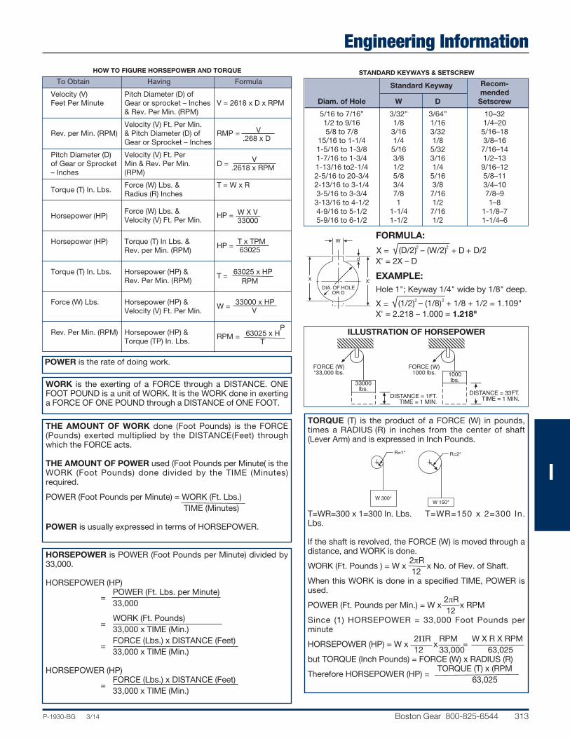
Engineering Information
P-1930-BG 3/14 Boston Gear 800-825-6544 313
HOW TO FIGURE HORSEPOWER AND TORQUE
To Obtain Having Formula
Velocity (V) Pitch Diameter (D) of Feet Per Minute Gear or sprocket – Inches V = 2618 x D x RPM & Rev. Per Min. (RPM)
Velocity (V) Ft. Per Min. V Rev. per Min. (RPM) & Pitch Diameter (D) of RMP =
Gear or Sprocket – Inches .268 x D
Pitch Diameter (D) Velocity (V) Ft. Per V of Gear or Sprocket Min & Rev. Per Min. D =
– Inches (RPM) .2618 x RPM
Torque (T) In. Lbs.
Force (W) Lbs. & T = W x R Radius (R) Inches
Horsepower (HP)
Force (W) Lbs. &
W X V
Velocity (V) Ft. Per Min. HP =
33000
Horsepower (HP)
Torque (T) In Lbs. &
T x TPM Rev. per Min. (RPM)
HP =
63025
Torque (T) In. Lbs.
Horsepower (HP) &
63025 x HP Rev. Per Min. (RPM)
T = RPM
Force (W) Lbs.
Horsepower (HP) &
33000 x HP
Velocity (V) Ft. Per Min. W =
V
Rev. Per Min. (RPM)
Horsepower (HP) &
63025 x H
P
Torque (TP) In. Lbs. RPM =
T
POWER is the rate of doing work.
WORK is the exerting of a FORCE through a DISTANCE. ONEFOOT POUND is a unit of WORK. It is the WORK done in exertinga FORCE OF ONE POUND through a DISTANCE of ONE FOOT.
THE AMOUNT OF WORK done (Foot Pounds) is the FORCE(Pounds) exerted multiplied by the DISTANCE(Feet) throughwhich the FORCE acts.
THE AMOUNT OF POWER used (Foot Pounds per Minute( is theWORK (Foot Pounds) done divided by the TIME (Minutes)required.
POWER (Foot Pounds per Minute) = WORK (Ft. Lbs.) TIME (Minutes)
POWER is usually expressed in terms of HORSEPOWER.
STANDARD KEYWAYS & SETSCREW
Standard Keyway Recom- mended Diam. of Hole W D Setscrew
5/16 to 7/16” 3/32” 3/64” 10–32 1/2 to 9/16 1/8 1/16 1/4–20 5/8 to 7/8 3/16 3/32 5/16–18 15/16 to 1-1/4 1/4 1/8 3/8–16 1-5/16 to 1-3/8 5/16 5/32 7/16–14 1-7/16 to 1-3/4 3/8 3/16 1/2–13 1-13/16 to2-1/4 1/2 1/4 9/16–12 2-5/16 to 20-3/4 5/8 5/16 5/8–11 2-13/16 to 3-1/4 3/4 3/8 3/4–10 3-5/16 to 3-3/4 7/8 7/16 7/8–9 3-13/16 to 4-1/2 1 1/2 1–8 4-9/16 to 5-1/2 1-1/4 7/16 1-1/8 –7 5-9/16 to 6-1/2 1-1/2 1/2 1-1/4–6
X X'
d
W
DIA. OF HOLEOR D
FORMULA:
X' = 2X – D
EXAMPLE:Hole 1"; Keyway 1/4" wide by 1/8" deep.
X' = 2.218 – 1.000 = 1.218"
DISTANCE = 33FT.TIME = 1 MIN.
33000lbs.
1000lbs.
FORCE (W)1000 lbs.
FORCE (W)*33,000 lbs.
DISTANCE = 1FT.TIME = 1 MIN.
TORQUE (T) is the product of a FORCE (W) in pounds,times a RADIUS (R) in inches from the center of shaft(Lever Arm) and is expressed in Inch Pounds.
T=WR=300 x 1=300 In. Lbs. T=WR=150 x 2=300 In.Lbs.
If the shaft is revolved, the FORCE (W) is moved through adistance, and WORK is done. 2pRWORK (Ft. Pounds ) = W x x No. of Rev. of Shaft. 12When this WORK is done in a specified TIME, POWER isused. 2pRPOWER (Ft. Pounds per Min.) = W x x RPM 12Since (1) HORSEPOWER = 33,000 Foot Pounds perminute 2pR RPM W X R X RPMHORSEPOWER (HP) = W x x = 12 33,000 63,025but TORQUE (Inch Pounds) = FORCE (W) x RADIUS (R) TORQUE (T) x (RPMTherefore HORSEPOWER (HP) = 63,025
W 300* W 150*
R=1* R=2*
HORSEPOWER is POWER (Foot Pounds per Minute) divided by33,000.
HORSEPOWER (HP) POWER (Ft. Lbs. per Minute) = 33,000
WORK (Ft. Pounds) = 33,000 x TIME (Min.) FORCE (Lbs.) x DISTANCE (Feet) = 33,000 x TIME (Min.)
HORSEPOWER (HP) FORCE (Lbs.) x DISTANCE (Feet) = 33,000 x TIME (Min.)
ILLUSTRATION OF HORSEPOWER
I

314 Boston Gear 800-825-6544 P-1930-BG 3/14
Engineering InformationGeneral
MountingSPUR & HELICALFor proper functioning gears, gears must be accuratelyaligned and supported by a shaft and bearing system whichmaintains alignment under load. Deflection should not exceed.001 inch at the tooth mesh for general applications. The tolerance on Center Distance normally should be positive toavoid possibility of gear teeth binding. Tolerance value isdependent on acceptable system backlash. As a guide foraverage application, this tolerance might vary from .002 forBoston Gear’s fine pitch gears to .005 for the coarsest pitch.
WORMS AND WORM GEARIt is important that the mounting assures the central plane ofthe Worm gear passes essentially through the axis of theWorm. This can be accomplished by adjusting the WormGear axially. Boston Worm Gears are cut to close tolerancingof the Center Line of the Gear tooth to the flush side of theGear. When properly mounted Worm Gears will become moreefficient after initial break-in period.
HOW WORM GEARS “ADJUST” THEMSELVESThe gear in a worm gear reducer is made of a soft bronzematerial. Therefore, it can cold-work and wear-in to accommodate slight errors in misalignment.
Evolution of Contact in a Worm Gear
Initially, contact is concentrated on the leavingside of the worm.
After several hours or running under load, gearhas cold-worked to spreadarea of contact.
After many hours of operation, contact hasspread to cover the entireworking area of the tooth.
AlterationsBoston Gear Service Centers are equipped to alter catalogsprockets (rebore, keyway, setscrew, etc.). For customers,choosing to make their own alterations, the guidelines listedbelow should be beneficial. Alterations to hardened gearsshould not be made without consultation with factory.In setting up for reboring the most important consideration isto preserve the accuracy of concentricity and lateral runoutprovided in the original product. There are several methodsfor accomplishing this. One procedure is: mount the part onan arbor, machine hub diameter to provide a true running surface, remove from arbor and chuck on the hub diameter,check face and bore runout prior to reboring. As a basic ruleof thumb, the maximum bore should not exceed 60% of theHub Diameter and depending on Key size should be checkedfor minimum wall thickness. A minimum of one setscrewdiameter over a keyway is considered adequate.Boston Gear offers a service for hardening stock sprockets.This added treatment can provide increased horsepowercapacity with resultant longer life and/or reduction in size andweight.Customers wishing to do the hardening operation shouldrefer to “Materials” below for information.
LubricationThe use of a straight mineral oil is recommended for mostworm gear applications. This type of oil is applicable to gearsof all materials, including non-metallic materials.Mild E.P. (Extreme Pressure) lubricants may be used with Ironand Steel Gears. E.P. lubricants normally should be selectedof the same viscosity as straight mineral oil, E.P. lubricantsare not recommended for use with brass or bronze gears.SAE80 or 90 gear oil should be satisfactory for splash lubricated gears. Where extremely high or low speed conditions are encountered, consult a lubricant manufacturer.Oil temperature of 150°F should not be exceeded for continuous duty applications. Temperatures up to 200°F canbe safely tolerated for short periods of time.Many specialty lubricants have been recently developed tomeet the application demands of today’s markets, includingsynthetics and both high and low temperature oils and greases. In those instances where Bath or Drip Feed is notpractical, a moly-Disulphide grease may be used successfully, for low speed applications.
Wormrotation
LeavingsideEntering
side
I

P-1930-BG 3/14 Boston Gear 800-825-6544 315
Engineering InformationGeneral
MaterialsBoston Gear stock steel gears are made from a .20 carbonsteel with no subsequent treatment. For those applicationsrequiring increased wearability. Case-hardening produces awear resistant, durable surface and a higher strength core.Carburizing and hardening is the most common processused. Several proprietary nitriding processes are available for producing an essentially distortion-free part with a relativelyshallow but wear-resistant case. Boston stock worms aremade of either a .20 or .45 carbon steel. Selection of materialis based on size and whether furnished as hardened oruntreated.
Stock cast iron gears are manufactured from ASTM-CLASS30 cast iron to Boston Gear specifications. This provides afine-grained material with good wear-resistant properties.
Bronze worm and helical gears are produced from severalalloys selected for bearing and strength properties. Phosphorbronze is used for helicals and some worm gears (12P andcoarser). Finer pitch worm gears are made from several different grades of bronze, dependent on size.
Non-metallic spur Gears listed in this Catalog are made fromcotton reinforced phenolic normally referred to as Grade “C.”
Plastic Gears listed are molded from either Delrin®, Acetal orMinlon®.
StylesBoston Spur, Helical, and Worm Gears are carried in Plain,Web, or Spoke styles, as illustrated.
WEB WITHLIGHTNING HOLES – C
PLAIN – A
WEB – B
SPOKE – D
STANDARD KEYWAYS AND SETSCREWS
Standard Recommended Diameter of Hole W d Setscrew
5/16 to 7/16” 3/32” 3/64” 10-32 1/2 to 9/16 1/8 1/16 1/4-20 5/8 to 7/8 3/16 3/32 5/16-18 15/16 to 1-1/4 1/4 1/8 3/8-16 1-5/16 to 1-3/8 5/16 5/32 7/16-14 1-7/16 to 1-3/4 3/8 3/16 1/2-13 1-13/16 to 2-1/4 1/2 1/4 9/16-12 2-5/16 to 2-3/4 5/8 5/16 5/8-11 2-13/16 to 3-1/4 3/4 3/8 3/4-10 3-5/16 to 3-3/4 7/8 7/16 7/8-9 3-13/16 to 4-1/2 1 1/2 1-8 4-9/16 to 5-1/2 1-1/4 7/16 1-1/8-7 5-9/16 to 6-1/2 1-1/2 1/2 1-1/4-6
DIA. OF HOLEOR D
W
d
X'
X
Formula:
X’ = 2X – D
Example:Hole 1”; Keyway 1/4” wide by 1/8” deep.
X’ = 2.218 – 1.000 = 1.218”
X = (D/2) – (W/2) + d + D/22 2
X
X = (1/2) – (1/8) + 1/8 + 1/2 = 1.109"2 2
W
I

316 Boston Gear 800-825-6544 P-1930-BG 3/14
Sprockets
AlterationsBoston Gear Service Centers are equipped to alter catalogsprockets (rebore, keyway, setscrew, etc.). For customers,choosing to make their own alterations, the guidelines listedbelow should be beneficial. Alterations to hardened gearsshould not be made without consultation with factory.In setting up for reboring the most important consideration isto preserve the accuracy of concentricity and lateral runoutprovided in the original product. There are several methods foraccomplishing this. One procedure is: mount the part on anarbor, machine hub diameter to provide a true running surface, remove from arbor and chuck on the hub diameter,check face and bore runout prior to reboring. As a basic ruleof thumb, the maximum bore should not exceed 60% of theHub Diameter and depending on Key size should be checkedfor minimum wall thickness. A minimum of one setscrew diameter over a keyway is considered adequate.Boston Gear offers a service for hardening stock sprockets.This added treatment can provide increased horsepowercapacity with resultant longer life and/or reduction in size andweight.Customers wishing to do the hardening operation should referto “Materials” below for information.
MaterialsPlasticPlastic sprockets listed are molded from Nylatron GS.
SteelType B one-piece sprockets are furnished in a free-machining,low carbon steel.Plate sprockets (Type A) and two-piece construction (Type B)are made of low carbon steel (basically AISI 1020).1/4” pitch (Type B) up to 20 teeth is furnished from sinteredmetal powder conforming to ASTM-B-426-70 Grade 1, TypeIII with hardness of RB60 MIN.
Stainless Steel1/4, 3/8 and 1/2” Pitches stock bore, single strand are furnished from 303 free-machining Stainless Steel.
Cast IronBlock Chain Sprockets are furnished in Cast Iron for 9 through12 teeth, which conforms to ASTM-A48-Class 30 Cast Iron,providing a fine-grained material with good wear resistantproperties.
Overhung Load
Overhung load is introduced on a shaft by the sprocket, gear,or belt from which the shaft is driven. A shaft driven by a properly installed flexible coupling would not have an overhung load.
The magnitude of the overhung load is determined by the loadat the driving or driven member and the distance this memberis from the nearest shaft support bearing. Overhung load willreduce the safe power transmission capacity of any shaft,therefore, every effort must be made to reduce this load.There are two ways to reduce this load (1) reduce the supportdistance or (2) increase the diameter of the driving and drivenmember. In most cases, increasing the size of a drive is notpossible and therefore, all effort should be made to reduce thesupport distance.
MINIMUMDISTANCE
MAXIMUMDIAMETER
STANDARD KEYWAYS AND SETSCREWS
Standard Keyway Recommended
Diameter of Hole W D Setscrew
5/16 to 7/16 “ 3/32” 3/64” 10–32 1/2 to 9/16 1/8 1/16 1/4–20 5/8 to 7/8 3/16 3/32 5/16–18 15/16 to 1-1/4 1/4 1/8 3/8–16 1-5/16 to 1-3/8 5/16 5/32 7/16–14 1-7/16 to 1-3/4 3/8 3/16 1/2–13 1-13/16 to 2-1/4 1/2 1/4 9/16–12 2-5/16 to 2-3/4 5/8 5/16 5/8–11 2-13/16 to 3-1/4 3/4 3/8 3/4–10 3-5/16 to 3-3/4 7/8 7/16 7/8–9 3-13/16 to 4-1/2 1 1/2 1–8 4-9/16 to 5-1/2 1-1/4 7/16 1-1/8–7 5-9/16 to 6-1/2 1-1/2 1/2 1-1/4–6
X X'
d
W
DIA. OF HOLEOR D
FORMULA:
X' = 2X – D
EXAMPLE:Hole 1"; Keyway 1/4" wide by 1/8" deep.
X' = 2.218 – 1.000 = 1.218"
Engineering Information
I

Sprocket Diameters for ANSI Standard Series
Engineering Information
P-1930-BG 3/14 Boston Gear 800-825-6544 317
1/4” Pitch–No. 25 3/8” Pitch–No. 35 1/2” Pitch–No. 40 1/2” Pitch–No. 41 Number .130” Roller Diameter .200” Roller Diameter .312” Roller Diameter .306” Roller Diameter of Pitch Outside Bottom Pitch Outside Bottom Pitch Outside Bottom Pitch Outside Bottom Teeth Diameter Diameter Diameter Diameter Diameter Diameter Diameter Diameter Diameter Diameter Diameter Diameter
9 0.731 0.83 0.601 1.096 1.26 0.896 1.462 1.67 1.149 1.462 1.67 1.156 10 0.809 0.91 0.679 1.214 1.38 1.014 1.618 1.84 1.305 1.618 1.84 1.312 11 0.887 1.00 0.757 1.331 1.50 1.131 1.775 2.00 1.462 1.775 2.00 1.469 12 0.966 1.08 0.836 1.449 1.63 1.249 1.932 2.17 1.619 1.932 2.17 1.626 13 1.045 1.16 0.915 1.567 1.75 1.367 2.089 2.33 1.776 2.089 2.33 1.783 14 1.124 1.24 0.994 1.685 1.87 1.485 2.247 2.49 1.934 2.247 2.49 1.941 15 1.203 1.32 1.073 1.804 1.99 1.604 2.405 2.65 2.092 2.405 2.65 2.099 16 1.282 1.40 1.152 1.922 2.11 1.722 2.563 2.81 2.250 2.563 2.81 2.257 17 1.361 1.48 1.231 2.041 2.23 1.841 2.721 2.98 2.408 2.721 2.98 2.415 18 1.440 1.56 1.310 2.160 2.35 1.960 2.879 3.14 2.566 2.879 3.14 2.573 19 1.519 1.64 1.389 2.278 2.47 2.078 3.038 3.30 2.725 3.038 3.30 2.732 20 1.598 1.72 1.468 2.397 2.59 2.197 3.196 3.46 2.883 3.196 3.46 2.890 21 1.678 1.80 1.548 2.516 2.71 2.316 3.355 3.62 3.042 3.355 3.62 3.049 22 1.757 1.88 1.627 2.635 2.83 2.435 3.513 3.78 3.200 3.513 3.78 3.207 23 1.836 1.96 1.706 2.754 2.95 2.554 3.672 3.94 3.359 3.672 3.94 3.366 24 1.915 2.04 1.785 2.873 3.07 2.673 3.831 4.10 3.518 3.831 4.10 3.525 25 1.995 2.12 1.865 2.992 3.19 2.792 3.989 4.26 3.676 3.989 4.26 3.683 26 2.074 2.20 1.944 3.111 3.31 2.911 4.148 4.42 3.835 4.148 4.42 3.842 27 2.154 2.28 2.024 3.230 3.43 3.030 4.307 4.58 3.994 4.307 4.58 4.001 28 2.233 2.36 2.103 3.349 3.55 3.149 4.466 4.74 4.153 4.466 4.74 4.159 30 2.392 2.52 2.262 3.588 3.79 3.388 4.783 5.06 4.470 4.783 5.06 4.477 31 2.471 2.60 2.341 3.707 3.91 3.507 4.942 5.22 4.629 4.942 5.22 4.636 32 2.551 2.68 2.421 3.826 4.03 3.626 5.101 5.38 4.789 5.101 5.38 4.794 33 2.630 2.76 2.500 3.945 4.15 3.745 5.260 5.54 4.947 5.260 5.54 4.954 34 2.710 2.84 2.580 4.064 4.27 3.864 5.419 5.70 5.106 5.419 5.70 5.113 35 2.789 2.92 2.659 4.183 4.39 3.983 5.578 5.86 5.265 5.578 5.86 5.272 36 2.869 3.00 2.739 4.303 4.51 4.103 5.737 6.02 5.424 5.737 6.02 5.431 38 3.028 3.16 2.898 4.541 4.75 4.341 6.055 6.33 5.742 6.055 6.33 5.749 39 3.107 3.24 2.977 4.660 4.87 4.460 6.214 6.49 5.901 6.214 6.49 5.908 40 3.187 3.32 3.693 5.734 5.95 5.534 7.645 7.93 7.332 7.645 7.93 7.339 41 3.266 3.40 3.136 4.899 5.11 4.699 6.532 6.81 6.219 6.532 6.81 6.226 42 3.346 3.48 3.216 5.018 5.23 4.818 6.691 6.97 6.378 6.691 6.97 6.385 44 3.505 3.64 3.375 5.257 5.47 5.057 7.009 7.29 6.696 7.009 7.29 6.703 45 3.584 3.72 3.454 5.736 5.59 5.176 7.168 7.45 6.855 7.168 7.45 6.862 48 3.823 3.96 3.693 5.734 5.95 5.534 7.645 7.93 7.332 7.645 7.93 7.339 52 4.141 4.28 4.011 6.211 6.43 6.011 8.281 8.57 7.968 8.281 8.57 7.975 54 4.300 4.44 4.170 6.449 6.66 6.249 8.599 8.89 8.286 8.599 8.89 8.294 56 4.459 4.60 4.329 6.688 6.90 6.488 8.917 9.20 8.605 8.917 9.20 8.611 60 4.777 4.92 4.647 7.165 7.38 6.965 9.554 9.84 9.241 9.554 9.84 9.246 64 5.095 5.23 4.965 7.643 7.86 7.443 10.190 10.48 9.877 10.190 10.48 9.883 65 5.175 5.31 5.045 7.762 7.98 7.562 10.349 10.64 10.036 10.349 10.64 10.044 66 5.254 5.39 5.124 7.881 8.10 7.681 10.508 10.80 10.195 10.508 10.80 10.202 70 5.572 5.71 5.442 8.358 8.58 8.158 11.145 11.43 10.832 11.145 11.43 10.840 72 5.732 5.87 5.602 8.597 8.81 8.397 11.463 11.75 11.150 11.463 11.75 11.156 80 6.368 6.51 6.238 9.552 9.77 9.352 12.736 13.03 12.423 12.736 13.03 12.430 84 6.686 6.83 6.556 10.029 10.25 9.829 13.372 13.66 13.059 13.372 13.66 13.067 96 7.641 7.78 7.511 11.461 11.68 11.261 15.281 15.57 14.969 15.281 15.57 14.976
I

Sprocket Diameters for ANSI Standard Series Hubs
Engineering Information
318 Boston Gear 800-825-6544 P-1930-BG 3/14
5/8” Pitch–No. 50 3/4” Pitch–No. 60 1” Pitch–No. 80 No. .400” Roller Diameter .468” Roller Diameter .625” Roller Diameter
of Pitch Outside Bottom Pitch Outside Bottom Pitch Outside Bottom
Teeth
Diameter Diameter Diameter Diameter Diameter Diameter Diameter Diameter Diameter 9 1.87 2.09 1.427 2.193 2.51 1.724 2.924 3.35 2.299 10 2.023 2.30 1.623 2.427 2.76 1.958 3.236 3.68 2.611 11 2.218 2.50 1.818 2.662 3.00 2.193 2.549 4.01 2.924 12 2.415 2.71 2.015 2.898 3.25 2.429 3.864 4.33 3.239 13 2.612 2.91 2.212 3.134 3.49 2.665 4.179 4.66 3.554 14 2.809 3.11 2.409 3.371 3.74 2.902 4.494 4.98 3.869 15 3.006 3.32 2.606 3.607 3.98 3.138 4.180 5.31 4.185 16 3.204 3.52 2.804 3.844 4.22 3.375 5.126 5.63 4.501 17 3.401 3.72 3.001 4.082 4.46 3.613 5.442 5.95 4.817 18 3.599 3.92 3.199 4.319 4.70 3.850 5.759 6.27 5.134 19 3.797 4.12 3.397 4.557 4.95 4.088 6.076 6.59 5.451 20 3.995 4.32 3.595 4.794 5.19 4.325 6.393 6.91 5.768 21 4.193 4.52 3.793 5.032 5.43 4.563 6.710 7.24 6.085 22 4.392 4.72 3.992 5.270 5.67 4.801 7.027 7.56 6.402 23 4.590 4.92 4.190 5.508 5.91 5.039 7.344 7.88 6.719 24 4.788 5.12 4.388 5.746 6.15 5.277 7.661 8.20 7.036 25 4.987 5.32 4.587 5.984 6.39 5.515 7.979 8.52 7.354 26 5.185 5.52 4.785 6.222 6.63 5.753 8.296 8.84 7.671 28 5.582 5.92 5.182 6.699 7.11 6.230 8.931 9.48 8.306 30 5.979 6.32 5.579 7.175 7.59 6.706 9.567 10.11 8.942 32 6.376 6.72 5.976 7.652 8.07 7.183 10.202 10.75 9.577 34 6.774 7.12 6.374 8.128 8.54 7.659 10.838 11.39 10.213 35 6.972 7.32 6.572 8.367 8.78 7.898 11.156 11.71 10.531 36 7.171 7.52 6.771 8.605 9.02 8.136 11.474 12.03 10.849 37 7.370 7.72 6.970 8.844 9.26 8.375 11.792 12.35 11.167 38 7.569 7.92 7.169 9.082 9.50 8.613 12.110 12.67 11.485 40 7.966 8.32 7.566 9.559 9.98 9.090 12.746 13.31 12.121 42 8.363 8.72 7.963 10.036 10.46 9.567 13.382 13.94 12.757 44 8.761 9.11 8.361 10.513 10.94 10.044 14.018 14.58 13.393 45 8.960 9.31 8.560 10.752 11.18 10.283 14.336 14.90 13.711 48 9.556 9.91 9.156 11.467 11.89 10.998 15.290 15.86 14.665 49 9.755 10.11 9.355 11.706 12.13 11.237 15.608 16.18 14.983 50 9.954 10.31 9.554 11.945 12.37 11.476 15.926 16.50 15.301 52 10.351 10.71 9.951 12.422 12.85 11.953 16.562 17.13 15.937 54 10.749 11.11 10349 12.899 13.33 12.430 17.198 17.77 16.573 56 11.147 11.50 10.747 13.376 13.81 12.907 17.835 18.41 17.210 60 11.942 12.30 11.542 13.330 14.76 13.861 19.107 19.68 18.482 64 12.738 13.10 12.338 15.285 15.72 14.816 20.380 20.96 19.755 70 13.931 14.29 13.531 16.717 17.15 16.248 22.289 22.87 21.664 72 14.329 14.69 13.929 17.194 17.63 16.725 22.926 23.50 22.301 76 15.124 15.49 14.724 18.149 18.58 17.680 24.199 24.78 23.574 80 15.920 16.28 15.520 19.103 19.54 18.634 25.471 26.05 24.846 84 16.715 17.08 16.315 20.058 20.49 19.589 26.744 27.33 26.119 90 17.909 18.27 17.509 21.490 21.93 21.021 28.654 29.24 28.029 96 19.102 19.47 18.702 22.922 23.36 22.453 30.563 31.15 29.938
I

Engineering InformationHorsepower & Torque Capacity of Shafting
P-1930-BG 3/14 Boston Gear 800-825-6544 319
Shaft Horsepower Based on Pure Torsion Torque Capacity at 10,000 PSI Maximum Shear Stress (Lb. Ins.) Diameter Based on 10,000 PSI 30 50 100 175 690 1150 1750 Shear Stress
3/8 0.049 0.082 0.164 0.287 1.13 1.88 2.87 103 7/16 0.078 0.130 0.261 0.456 1.79 2.99 4.56 164 1/2 0.117 0.194 0.389 0.681 2.68 4.47 6.80 245 9/16 0.166 0.277 0.554 0.969 3.82 6.36 9.69 349 5/8 0.228 0.380 0.760 1.32 5.24 8.73 13.2 479 11/16 0.303 0.506 1.01 1.76 6.97 11.6 17.6 637 3/4 0.394 0.656 1.31 2.29 9.05 15.0 22.9 827 13/16 0.501 0.834 1.66 2.92 11.5 19.1 29.2 1052 7/8 0.625 1.04 2.08 3.64 14.3 23.9 36.4 1314 15/16 0.769 1.28 2.56 4.48 17.6 29.4 44.3 1616 1 0.933 1.55 3.11 5.44 21.4 35.7 54.4 1961 1-1/16 1.12 1.86 3.73 6.53 25.7 42.9 65.3 2352 1-1/8 1.32 2.21 4.43 7.75 30.5 50.9 77.5 2792 1-3/16 1.56 2.60 5.21 9.11 35.9 59.9 91.1 3283 1-1/4 1.82 3.03 6.07 10.6 41.9 69.8 106 3830 1-5/16 2.11 3.51 7.03 12.3 48.5 80 123 4433 1-3/8 2.42 4.04 8.08 11.1 55.8 93 141 5097 1-7/16 2.77 4.62 9.24 16.1 63.7 106 161 5824 1-1/2 3.15 5.25 10.5 18.3 72.4 120 183 6618 1-9/16 3.56 5.93 11.8 20.7 81.8 136 207 7480 1-5/8 4.00 6.67 13.3 23.3 92.1 153 233 8414 1-11/16 4.48 7.47 14.9 26.1 103.1 171 261 9422 1-3/4 5.00 8.33 16.6 29.1 115.0 191 291 10509 1-13/16 5.55 9.26 18.5 32.4 127.8 213 324 11675 1-7/8 6.15 10.2 20.5 35.8 141.5 235 358 12925 1-15/16 6.78 11.3 22.6 39.6 156.1 260 396 14261 2 7.46 12.4 24.8 43.5 171.7 286 435 15686 2-1/16 8.18 13.6 27.2 47.7 188.3 313 477 17203 2-1/8 8.95 14.9 29.8 52.2 206.0 343 522 18815 2-3/16 9.77 16.2 32.5 56.9 224.7 374 569 20525 2-1/4 10.6 17.7 35.4 62.0 244.5 407 620 22335 2-5/16 11.5 19.2 38.4 67.3 265.4 442 673 24248 2-3/8 12.5 20.8 41.6 72.9 287.6 479 729 26268 2-7/16 13.5 22.5 45.0 78.8 310.9 518 788 29396 2-1/2 14.5 24.3 48.6 85.0 335.1 559 850 30637 2-9/16 15.7 26.1 52.3 91.6 361.2 602 916 32993 2-5/8 16.8 28.1 56.2 98.4 388.3 647 984 35466
The above table is computed based on a torsional stress of 10,000 PSI. For applications involvingbending moments (gears, sprockets, etc.) the horsepower capacity must be reduced accordingly.
The stress level of 10,000 PSI is representative of medium carbon steel shafting. For other materials, acorrection must be made accordingly.
I

Temperature Conversion TableDegrees Celcius “C”; Degrees Fahrenheit “F”
Engineering Information
320 Boston Gear 800-825-6544 P-1930-BG 3/14
Degree Degree C. F.
–40 –40.0 –39 –38.2 –38 –36.4 –37 –34.6 –36 –32.8
–35 –31.0 –34 –29.2 –33 –27.4 –32 –25.6 –31 –23.8
–30 –22.0 –29 –20.2 –28 –18.4 –27 –16.6 –26 –14.8
–25 –13.0 –24 –11.2 –23 – 9.4 –22 – 7.6 –21 – 5.8
–20 – 4.0 –19 – 2.2 –18 – 0.4 –17 + 1.4 –16 3.2
–15 5.0 –14 6.8 –13 8.6 –12 10.4 –11 12.2
–10 14.0 – 9 15.8 – 8 17.6 – 7 19.4 – 6 21.2
– 5 23.0 – 4 24.8 – 3 26.6 – 2 28.4 – 1 30.2
0 32.0 + 1 33.8 2 35.6 3 37.4 4 39.2
5 41.0 6 42.8 7 44.5
Degree Degree C. F.
8 46.4 9 48.2 10 50.0 11 51.8 12 53.6
13 55.4 14 57.2 15 59.0 16 60.8 17 62.6
18 64.4 19 66.2 20 68.0 21 69.8 22 71.6
23 73.4 24 75.2 25 77.0 26 78.8 27 80.6
28 82.4 29 84.2 30 86.0 31 87.8 32 89.6
33 91.4 34 93.2 35 95.0 36 96.8 37 98.6
38 100.4 39 102.2 40 104.0 41 105.8 42 107.6
43 109.4 44 111.2 45 113.0 46 114.8 47 116.6
48 118.4 49 120.2 50 122.0 51 123.8 52 125.6
53 127.4 54 129.2 55 131.0
Degree Degree C. F.
56 132.8 57 134.6 58 136.4 59 138.2 60 140.0
61 141.8 62 143.6 63 145.4 64 147.2 65 149.0
66 150.8 67 152.6 68 154.4 69 156.2 70 158.0
71 159.8 72 161.6 73 163.4 74 165.2 75 167.0
76 168.8 77 170.6 78 172.4 79 174.2 80 176.0
81 177.8 82 179.6 83 181.4 84 183.2 85 185.0
86 186.8 87 188.6 88 190.4 89 192.2 90 194.0
91 195.8 92 197.6 93 199.4 94 201.2 95 203.0
96 204.8 97 206.6 98 208.4 99 210.2 100 212.0
101 213.8 102 215.6 103 217.4
Degree Degree C. F.
104 219.2 105 221.0 106 222.8 107 224.6 108 226.4
109 228.2 110 230.0 111 231.8 112 233.6 113 235.4
114 237.2 115 239.0 116 240.8 117 242.6 118 244.4
119 246.2 120 248.0 121 249.8 122 251.6 123 253.4
124 255.2 125 257.0 126 258.8 127 260.6 128 262.4
129 264.2 130 266.0 131 267.8 132 269.6 133 271.4
134 273.2 135 275.0 136 276.8 137 278.6 138 280.4
139 282.2 140 284.0 141 285.8 142 287.6 143 289.4
144 291.2 145 293.0 146 294.8 147 296.6 148 298.4
149 300.2 150 302.0 151 303.8
Degree Degree C. F.
152 305.6 153 307.4 154 309.2 155 311.0 156 312.8
157 314.6 158 316.4 159 318.2 160 320.0 161 321.8
162 323.6 163 325.4 164 327.2 165 329.0 166 330.8
167 332.6 168 334.4 169 336.2 170 338.0 171 339.8
172 341.6 173 343.4 174 345.2 175 347.0 176 348.8
177 350.6 178 352.4 179 354.2 180 356.0 181 357.8
182 359.6 183 361.4 184 363.2 185 365.0 186 366.8
187 368.6 188 370.4 189 372.2 190 374.0 191 375.8
192 377.6 193 379.4 194 381.2 195 383.0 196 384.8
197 386.6 198 388.4 199 390.2
I

Engineering InformationEquivalent Table
P-1930-BG 3/14 Boston Gear 800-825-6544 321
FRACTION — DECIMAL — MILLIMETER
Inch
Fraction Decimal
Millimeter
Inches
Equivalent Equivalent
1/64 .0156 .397 1/32 .0312 .794 3/64 .0469 1.191 1/16 .0625 1.588 5/64 .0781 1.984 3/32 .0937 2.381 7/64 .1094 2.778 1/8 .1250 3.175 9/64 .1406 3.572 5/32 .1562 3.969 11/64 .1719 4.366 3/16 .1875 4.763 13/64 .2031 5.159 7/32 .2187 5.556 15/64 .2344 5.953 1/4 .2500 6.350 17/64 .2656 6.747 9/32 .2812 7.144 19/64 .2969 7.541 5/16 .3125 7.938 21/64 .3281 8.334 11/32 .3437 8.731 23/64 .3594 9.128 3/8 .3750 9.525 25/64 .3906 9.922 13/32 .4062 10.319 27/64 .4219 10.716 7/16 .4375 11.113 29/64 .4531 11.509 15/32 .4687 11.906 31/64 .4844 12.303 1/2 .5000 12.700
Inch
Fraction Decimal
Millimeter
Inches
Equivalent Equivalent
33/64 .5156 13.097 17/32 .5312 13.494 35/64 .5469 13.891 9/16 .5625 14.288 37/64 .5781 14.684 19/32 .5937 15.081 39/64 .6094 15.478 5/8 .6250 15.875 41/64 .6406 16.272 21/32 .6562 16.669 43/64 .6719 17.066 11/16 .6875 17.463 45/64 .7031 17.859 23/32 .7187 18.256 47/64 .7344 18.653 3/4 .7500 19.050 49/64 .7656 19.447 25/32 .7812 19.844 51/64 .7969 20.241 13/16 .8125 20.638 53/64 .8281 21.034 27/32 .8437 21.431 55/64 .8594 21.828 7/8 .8750 22.225 57/64 .8906 22.622 29/32 .9062 23.019 59/64 .9219 23.416 15/16 .9375 23.813 61/64 .9531 24.209 31/32 .9687 24.606 63/64 .9844 25.003 1 1.0000 25.400
MILLIMETER — INCHES
Millimeters Inches
1 .0394 2 .0787 3 .1181 4 .1575 5 .1968 6 .2362 7 .2756 8 .3150 9 .3543 10 .3937 11 .4331 12 .4724 13 .5118 14 .5512 15 .5905 16 .6299 17 .6693 18 .7087 19 .7480 20 .7874 21 .8268 22 .8661 23 .9055 24 .9449 25 .9842 26 1.0236 27 1.0630 28 1.1024 29 1.1417 30 1.1811
I

322 Boston Gear 800-825-6544 P-1930-BG 3/14
AreaMultiply By To Obtain
Millimeters2 .00155 inches2
Centimeters2 .155 inches2
Meters2 10.76 feet2
Inches2 645.16 millimeters2
Inches2 6.452 centimeters2
Feet2 929.03 centimeters2
Feet2 .0929 meters2
DensityMultiply By To Obtain
lg/cm3 .03613 lb/in3
lg/cm3 62.43 lb/in3
lb/in3 27.68 gr/cm3
lb/ft3 .016 g/cm3
lb/ft3 16.02 Kg/m3
PowerMultiply By To Obtain
Joule/sec .001341 HorsepowerKilocalorie/hour 3.967 BTW/hourHorsepower .33000 ft-lb/minHorsepower 746 wattsBTU/hour .2521 kilocalorie/hour
LengthMultiply By To Obtain
Millimeter .03937 inchCentimeter .3937 inchMeter 39.37 inchInch 2.54 centimeterFeet 30.48 centimeterFeet .3048 meter
VolumeMultiply By To Obtain
Centimeter3 .0610 inches3
Centimeter3 .034 fluid ounceLiter 61.02 inches3
Liter .0353 feet3
Liter .264 U.S. gallonInch3 16.39 centimeter3
Feet3 28.32 literGallon 3.785 liter
WeightMultiply By To Obtain
Gram .03527 ounceKilogram 35.27 ounceKilogram 2.205 poundsOunce 28.35 gramPound 453.6 grams
TorqueMultiply By To Obtain
Newton-meter 8.84 in-lbin-lb .113 Newton-meter
VelocityMultiply By To Obtain
Centimeter/second .3937 inches/secondCentimeter/second 1.969 feet/minuteMeter/second 3.281 feet/secondMeter/second 196.9 feet/minuteMeter/second 2.237 miles per hourInch/second 25.4 millimeters/secondInch/second 2.54 centimeters/secondFoot/second .3048 meters/secondFoot/minute .00508 meters/second
Metric Conversion Chart
BOSTON GEAR REGISTERED TRADEMARKS
BOSTON GEAR®
BOSTON®
BOStonE®
BOST-BRONZ®
BEAR-N-BRONZ®
Engineering Information
I

Engineering Information
P-1930-BG 3/14 Boston Gear 800-825-6544 323
Application Classification for Various Loads
Chart I For All Drives
Service Factor Loading
Type of Machine Not More Not More MoreTo Be Driven Than 15 Than 10 Than
Mins. in Hrs. per 10 Hrs. 2 Hrs. Day Per Day
AGITATORS
Pure Liquid 0.80 1.00 1.25Semi-Liquids, Variable Density 1.00 1.25 1.50
BLOWERS
Centrifugal and Vane 0.80 1.00 1.25Lobe 1.00 1.25 1.50
BREWING AND DISTILLING
Bottling Machinery 0.80 1.00 1.25Brew Kettles–Continuous Duty — — 1.25Cookers – Continuous Duty — — 1.25Mash Tubs – Continuous Duty — — 1.25Scale Hopper – Frequent Starts — 1.25 1.50
CAN FILLING MACHINES — 1.00 —
CANE KNIVES — 1.50 —
CAR DUMPERS — 1.75 —
CAR PULLERS — 1.25 —
CLARIFIERS — 1.00 1.25
CLASSIFIERS — 1.25 1.50
CLAY WORKING MACHINERY
Brick Press & Briquette Machine — 1.75 2.00Extruders and Mixers 1.00 1.25 1.50
COMPRESSORS
Centrifugal — 1.00 1.25Lobe – Reciprocating, Multi-Cycle — 1.25 1.50Reciprocating – Single Cycle — 1.75 2.00
CONVEYORS—UNIFORMLY LOADED & FED
Apron — 1.00 1.25Assembly-Belt – Bucket or Pan — 1.00 1.25Chain – Flight — 1.00 1.25Oven – Live Roll – Screw — 1.25 1.50
CONVEYORS—HEAVY DUTYNOT UNIFORMLY FED
Apron — 1.25 1.50Assembly-Belt – Bucket or Pan — 1.25 1.50Chain – Flight — 1.25 1.50Live Roll — — —Oven – Screw — 1.25 1.50Reciprocating – Shaker — 1.75 2.00
CRANES AND HOISTS
Main HoistsBridge and Trolley Drive * 1.00 1.25
CRUSHER
Ore, Stone — 1.75 2.00Sugar — 1.50 1.50
Chart I For All Drives
Service Factor Loading
Type of Machine Not More Not More MoreTo Be Driven Than 15 Than 10 Than
Mins. in Hrs. per 10 Hrs. 2 Hrs. Day Per Day
ELEVATORS
Bucket – Uniform Load — 1.00 1.25Bucket – Heavy Load — 1.25 1.50Centrifugal Discharge — 1.25 1.50Freight — 1.25 1.50Gravity Discharge — 1.00 1.25 FANS
Centrifugal – Light (Small Diam.) — 1.00 1.25Large Industrial — 1.25 1.50
FEEDERS
Apron – Belt – Screw — 1.25 1.50Disc — 1.00 1.25
Reciprocating — 1.75 2.00
FOOD INDUSTRY
Beet Slicer — 1.25 1.50Cereal Cooker — 1.00 1.25Dough Mixer – Meat Grinder — 1.25 1.50
GENERATORS (NOT WELDING) — 1.00 1.25
HAMMER MILLS — 1.75 2.00
HOISTS
Heavy Duty — 1.75 2.00Medium Duty and Skip Type — 1.25 1.50LAUNDRY TUMBLERS — 1.25 1.50
LINE SHAFTS
Uniform Load — 1.00 1.25
Heavy Load — 1.25 1.50
MACHINE TOOLS
Auxiliary Drive — 1.00 1.25Main Drive – Uniform Load — 1.25 1.50Main Drive – Heavy Duty — 1.75 2.00
METAL MILLS
Draw Bench Carriers & Main Drive — 1.25 1.50
SLITTERS — 1.25 1.50
TABLE CONVEYORS —NON REVERSING
Group Drives — 1.25 1.50Individual Drives — 1.75 2.00Wiring Drawing, Flattening or Winding — 1.25 1.50
MILLS ROTARY TYPEBALL AND ROD
Spur Ring Gear and Direct Connected — — 2.00Cement Kilns, Pebble — — 1.50Dryers and Coolers — — 1.50Plain and Wedge Bar — — 1.50Tumbling Barrels — — 2.00
I

Application Classification for Various Loads (Continued)
Engineering Information
324 Boston Gear 800-825-6544 P-1930-BG 3/14
Chart I For All Drives
Service Factor Loading
Type of Machine Not More Not More MoreTo Be Driven Than 15 Than 10 Than
Mins. in Hrs. per 10 Hrs. 2 Hrs. Day Per Day
MIXERS
Concrete – Continuous — 1.25 1.50Concrete – Intermittent — 1.25 1.50Constant Density — 1.00 1.25Semi-Liquid — 1.25 1.50
OIL INDUSTRY
Oil Well Pumping — — *Chillers, Paraffin Filter Press — 1.25 1.50Rotary Kilns — 1.25 1.50
PAPER MILLS
Agitator (Mixer) — 1.25 1.50Agitator – Pure Liquids — 1.00 1.25Barking Drums – MechanicalBarkers — 1.75 2.00Bleacher — 1.00 1.25Beater — 1.25 1.50Calender Heavy Duty — — 2.00Calender Anti-Friction Brgs. — 1.00 1.25Cylinders — 1.25 1.50Chipper — — 2.00Chip Feeder — 1.25 1.50Coating Rolls – Couch Rolls — 1.00 1.25Conveyors – Chips – Bark – Chemical — 1.00 1.25Conveyors – Log and Slab — — 2.00Cutter — — 2.00Cylinder Molds, Dryers
(Anti-Friction Brg.) — — 1.25Felt Stretcher — 1.25 1.50Screens – Chip and Rotary — 1.25 1.50Thickener (AC) — 1.25 1.50Washer (AC) — 1.25 1.50Winder – Surface Type — — 1.25
PLASTICS INDUSTRY
Intensive Internal MixersBatch Type — — 1.75Continuous Type — — 2.00
Batch Drop Mill – 2 Rolls — — 1.25Compounding Mills — — 1.25Calenders — — 1.50Extruder – Variable Speed — — 1.50Extruder – Fixed Speed — — 1.75
PULLERS
Barge Haul — — 2.00
Chart I For All Drives
Service Factor Loading
Type of Machine Not More Not More MoreTo Be Driven Than 15 Than 10 Than
Mins. in Hrs. per 10 Hrs. 2 Hrs. Day Per Day
PUMPS
Centrifugal — — 1.25Proportioning — — 1.50Reciprocating
Single Acting, 3 or more Cycles — 1.25 1.50
Double Acting, 2 or more Cycles — 1.25 1.50
Rotary – Gear or Lube — 1.00 1.25
RUBBER INDUSTRY
Batch Mixers — — 1.75Continuous Mixers — — 1.50Calenders — — 1.50Extruders – Continuous — — 1.50Extruders – Intermittent — — 1.75Tire Building Machines — — —Tire & Tube Press Openers — — —SEWAGE DISPOSAL EQUIPMENT
Bar Screens — 1.00 1.25Chemical Feeders — 1.00 1.25Collectors — 1.00 1.25Dewatering Screws — 1.25 1.50Scum Breakers — 1.25 1.50Slow or Rapid Mixers — 1.25 1.50Thickeners — 1.25 1.50Vacuum Filters — 1.25 1.50
SCREENS
Air Washing — 1.00 1.25Rotary – Stone or Gravel — 1.25 1.50Traveling Water Intake — 1.00 1.25
SKIP HOISTS — — —SLAB PUSHERS — 1.25 1.50STOKERS — — 1.25
TEXTILE INDUSTRY
Batchers or Calenders — 1.25 1.50Cards — 1.25 1.50Card Machines — 1.75 2.00Dry Cans and Dryers — 1.25 1.50Dyeing Machines — 1.25 1.50Looms — 1.25 1.50Mangles, Nappers and Pads — 1.25 1.50Soapers, Tenner Frames — 1.25 1.50Spinners, Washers, Winders — 1.25 1.50
TUMBLING BARRELS 1.50 1.75 2.00
WINDLASS — 1.25 1.50
I

Index to Catalog Numbers
P-1930-BG 3/14 Boston Gear 800-825-6544 325
Catalog Number Description Page No. Catalog Number Description Page No.
*Initial number, larger numbers arranged according to size.
0-B(L)G* Chain Tensioners 294 0-H(U)G* Chain Tensioners 296 06000 Gear Gauge Set 62 06724* Thrust Washers 118 1 (A. AA) Ladder Chains 254
2 (1/2) Ladder Chains 254 2S(S)C12* Clamp Collars 2S(S)C25* Clamp Collars 117 3A-1/2* Adj. Shaft Supports 231 3A-1/2 B&C* Replacement Bearings 213
3F(T)-1/2* Flange Cartridges 225 3H(L)-1/2* Pillow Blocks 218 3M035060* Timing Belts 124 5M064150* Timing Belts 130 5R21-16S* Coupling Sleeve Stock
8P40AF(D,GS)-1/4* Roll End Bearings 166 12EMAF(D,GS)* Roll End Bearings 162 15BP(SS)7* Roller Chain Sprockets 266 25A(B)9* Roller Chain Sprockets 267 25B9SS* Roller Chain Sprockets 268
35A(B)8* Roller Chain Sprockets 269 35B9SS* Roller Chain Sprockets 271 35B12T1-8* Idler Sprockets 293 40A(B)9* Roller Chain Sprockets 274 40B10SS* Roller Chain Sprockets 278
40HP* Roller Chain 252 41A(B)22* Roller Chain Sprockets 272 50A(B)8* Roller Chain Sprockets 279 5(6)0-BG* Chain Tensioners 295 60A(B)8* Roller Chain Sprockets 283
60H* Roller Chain 245 80A(B)8* Roller Chain Sprockets 287 601* Ball Bearings 194 622AF(D,GS)-1/8* Roll End Bearings 162 1602DC(DS)* Ball Bearings 185
3002DC(DS)* Ball Bearings 190 7508DL(DLG)* Ball Bearings 187 7610DL(DLG)* Ball Bearings 188 11722* Shaft Couplings & Inserts 102 18510* Steel Bushings 119
18800* Steel Washers* 118 31300(4) Bear-N-Bronz Banks 154
A
A(AA1)* Roller Chain Attachments 251 AF1012-6* Bostone Bearings 161 AO1* Ball Bearings 193
B
B24-1* Bost-Bronz Bearings 138 B503* Block Chains 253 BBB-1 Bost-Bronz Bank 154 BF7-3/8-3/8* Shaft Couplings 102
BG11-1-3-3* Shaft Couplings 103 BG47-2-2* Shaft Couplings 103 BL423* Leaf Chains 253
C
C1-6* Ladder Chain Sprockets 292 C2040HP* Roller Chain 252 CA7* Ladder Chain Sprockets 291 CA(S)C18* Clamp Collars 116 CB1(A)6* Ladder Chain Sprockets 291
CB3-10* Lader Chain Sprockets 292 CB816* Bost-Bronz Cored Bars 144 CBT60* Chain Breakers 256 CD1142* Worm Gears 89 CFHD(L)-3* Rod Ends 200
CG1042* Worm Gears 89 CMHD(L)-3* Rod Ends 200 CQ1342* Worm Gears 89 CR4* Shaft Couplings 105 CS(S)C10-32* Clamp Collars 115 CSC12* Clamp Collars 116
D
D1 Roller Chain Attachments 251 D35B16* Roller Chain Sprockets 271 D40B13* Roller Chain Sprockets 278 D50B15* Roller Chain Sprockets 282 D60B15* Roller Chain Sprockets 286
D(B)620A* Worm Gears 93 D(B)860A* Worm Gears 92 D1080A Worm Gear 91 D1118* Worm Gears 86 D1126* Worm Gears 87
D1134* Worm Gears 88 D1142* Worm Gears 89 D1260A* Worm Gears 90 D(B)1400* Worm Gears 90 D1407K Worm 90
D(B)1410* Worm Gears 91 D1418K* Worms 91 D1418-10 Bostone Bearing 161 D(B)1420A* Worm Gears 92 D(B)1427K* Worms 92
D(B)1430A* Worm Gears 93 D1438(K)* Worms 93 D(B)1600* Worm Gears 90 D(B)1610* Worm Gears 91 D(B)1620A* Worm Gears 92
D(B)1630A* Worm Gears 93 DH1407* Worms 90 DH1418* Worms 91 DH1438* Worms 93 DSH-1 Worm 86
I

326 Boston Gear 800-825-6544 P-1930-BG 3/14
DTH-1 Worm 87 DUH Worm 88 DVH-1 Worm 89 DH1427* Worms 92
F
F7612B* Ball Bearing Insert 169 FA5-3/16-3/16* Shaft Coupling 105 FB25-2* Bost-Bronz Flanged Brgs. 141 FC12-3/8* Shaft Coupling 100 FC12-SOLID* Shaft Coupling 101
FCP21-1/8* Shaft Coupling 106 FH547* Roll End Adaptors 169 FP35-2* Bostone Flanged Brgs. 156
G
G(S)24* Pinion Wire 34 G96* Spur Gears 18 G182* Spur Gears 19 G226* Spur Gears 21 G460Y* Miter Gears 70
G478Y-G* Bevel Gears 74 G632* Internal Gears 36 G(B)850* Worm Gears 92 G1018* Worm Gears 86 G1026* Worm Gears 87
G1034* Worm Gears 88 G1042* Worm Gears 89 G(B)1050A* Worm Gears 90 G(B)1060A* Worm Gears 91 G1066K Worm 91
G(B)1070* Worm Gears 92 G1076K Worm 92 G(B)1077* Worm Gears 93 G1086K Worm 93 G(B)1100* Worm Gears 94
G1106KL(R) Worm 94 G1110* Worm Gears 95 G1116K Worm 95 G1202* Grooved Pulley 120 G(B)1260 Worm Gear 90
G1616GS-1/2 Guide Roll Bearing 170 G(B)8100* Worm Gears 92 GA20* Change Gears 28 GAB20A Compound Bushing 28 GB20* Change Gears 29
GBB16A* Compound Bushing 29 GD20A* Change Gears 30 GDB12A Compound Bushing 30 GDSH-1 Worm 86 GDTH-1 Worm 87
G1202* Pulleys 120
GDUH Worm 88 GDVH-1 Worm 89 GF20* Change Gears 31 GFB10A Compound Bushing 31 GH20* Change Gears 32
GH1056 Worm 90 GH1066 Worm 91 GH1076 Worm 92 GH1086 Worm 93 GHB8A Compound Bushing 32
GLSH-1 Worm 86 GLTH-1 Worm 87 GLUH Worm 88 GLVH-1 Worm 89 GP579-1* Racks 35
GP1018(-1/8)* Worm Gears 86 GP1026(-3/16)* Worm Gears 87 GP1034(-3/16)* Worm Gears 88 GP1616Y* Miter Gears 71 GP2424Y* Miter Gears 70
GQSH-1 Worm 86 GQTH-1 Worm 87 GQUH Worm 88 GQVH-1 Worm 89 GS48-7* Bostone Bearings 161
GSS460Y* Miter Gears 70 GSS479Y* Bevel Gears 74
H
H608L(R)* Helical Gears 65 H917 Block Chain Sprockets 290 H1008L(R)* Helical Gears 64 H1056* Worms 90 H1066* Worms 91
H1076* Worms 92 H1086* Worms 93 H1106 Worm 94 H1116 Worm 95 H1427L(R) Worms 92
H2412* Spur Gears 20 H3216* Spur Gears 19 HB612L(R)* Helical Gears 65 HDSH-1 Worm 86 HDTH-1 Worm 87
HDUH Worm 88 HDVH-1 Worm 89 HF(L)-3* Rod Ends 201 HF(L)-3C* Rod Ends 199 HF(L)-4CG* Rod Ends 199
HF(L)-4G* Rod Ends 201 HF(L)E-3* Rod Ends 202 HFX(L)-4G* Rod Ends 203
Index to Catalog NumbersCatalog Number Description Page No. Catalog Number Description Page No.
*Initial number, larger numbers arranged according to size.
I

Index to Catalog Numbers
P-1930-BG 3/14 Boston Gear 800-825-6544 327
HL146Y-G* Bevel Gears 75 HL147Y-G* Bevel Gears 74 HL153Y-G* Bevel Gears 76 HL156Y-G Bevel Gears 77
HL1056* Worms 90 HL1066* Worms 91 HL1076* Worms 92 HL1086* Worms 93 HL1106 Worm 94
HL1116 Worm 95 HLK101Y* Miter Gears 71 HLK105Y* Miter Gears 72 HLSH-1 Worm 86 HLSK101Y* Spiral Miter Gears 73
HLTH-1 Worm 87 HLUH Worm 88 HLVH-1 Worm 89 HM(L)-3* Rod Ends 201 HM(L)-3C* Rod Ends 199
HM(L)-4CG* Rod Ends 199 HM(L)-4G* Rod Ends 201 HM(L)E-3* Rod Ends 202 HMX(L)-4G* Rod Ends 203 HP1106 Worm 94
HQSH-1 Worm 86 HQTH-1 Worm 87 HQUH Worm 88 HQVH-1 Worm 89 HS608L(R)* Helical Gears 65
J
J37(A)* Universal Joints 108 J37(B)* Universal Joints 108 J37(B)-01* Universal Joint Parts 108 JP(D)25-1/8* Universal Joints 112 JPE37-1/8* Universal Joints 113
JS37(B)* Universal Joints 108
K
K(KK)1(2) Chain Attachments 251 KF(L)-3 Rod Ends 198
L
L93Y* Miter Gears 70 L99Y* Miter Gears 71 L105Y* Miter Gears 72 L146Y-G* Bevel Gears 75 L147Y-G* Bevel Gears 74
L153Y-G* Bevel Gears 76 L156Y-G* Bevel Gears 77 L204-4* Racks 47 L501-2* Racks 35 L1056* Worms 90
L1066* Worms 91 L1076 Worm 92 L1086* Worms 93 L1106 Worm 94 L1116 Worm 95
L1427 Worm 92 L1438 Worm 93 LHA(B,SS)2* Spherical Bearings 204 LHSSE(VV)2* Spherical Bearings 205 LS3* Spherical Bearings 206
LSA101Y* Spiral Miter Gears 73 LSH(P) Worms 86 LTHB(P) Worms 87 LUHB(P) Worms 88 LVHB-1 Worm 89
M
M1(35) Chain Attachments 251 M35(2) Chain Attachments 251 M35-4* Bear-N-Bronz Bearings 146 MB-1-7/16* Pillow Blocks 222 MBF-1-7/16* Flanged Cartridges 229
MBP-1-7/16* Piloted Flanges 230 MCB816* Bear-N-Bronz Cored Bars 151 MM1(35) Chain Attachments 251 MM1(35)(-2) Chain Attachments 251 MS8* Bear-N-Bronz Solid Bars 153
N
N6906(B)* Ball Bearings 189 NA11B(-5/16)* Spur Gears 20 NAR5* Steel Stem Pinions 33 NB11B(-3/8)* Spur Gears 21 NBG15-1/2* Replacement Bearings 214
ND11B(-1/2)* Spur Gears 22 NF11B(-5/8)* Spur Gears 23 NF35-2-1/2 Bostone Flanged Bearing 172 NH11B(-3/4)* Spur Gears 24 NJ11B(-1)* Spur Gears 25
NK11B* Spur Gears 26 NL11B* Spur Gears 27 NO11B* Spur Gears 27 NR2000* Ball Bearing Sheaves 195 NR2105* Ball Bearing Sheaves 196
NR2201* Ball Bearing Wheels 197 NS35-2-1/2* Bostone Bearings 172 NT312* Bostone Bearings 173 NX3008-(LC,M)* Replacement Bearings 213
O
OA424Y* Miter Gears 72
Catalog Number Description Page No. Catalog Number Description Page No.
*Initial number, larger numbers arranged according to size.
I

328 Boston Gear 800-825-6544 P-1930-BG 3/14
Index to Catalog Numbers
S(S)C12* Setscrew Collars 114 SCC1/4-1/4* Shaft Couplings 104 SF(T)-1/2* Flanged Cartridges 227 SH(L)-1/2* Pillow Blocks 220 SH(S)82-G(P)* Spiral Bevel Gears 78
SP4* Bostone F-1 Solid Bars 157 SRP-1/4* Pillow Blocks 215 SS4 Bostone Stub Shaft 171 SS82-G(P)* Spiral Bevel Gears 78
T
TB47* Bost-Bronz Thrust Brg. 143 TH35-60* Chain Pullers 256 TP410* Bostone Thrust Bearings 157 TU816-6* Take-Up Frames 232
U
UB37* Universal Joint Boot Kits 108 UJ(L,S)10(S,H)* Universal Joint Yokes 111 UJN(L,S)10-10* Universal Joints 110 UJ(L,S)(C,D) Universal Joint Center Kits 111
W
WA(1,2) Chain Attachments 251 WK(1,2) Chain Attachments 251 WM(1,2,35,35-2) Chain Attachments 251
X
X5R21-16 Shaft Coupling Part 106 XCBT60-5* Chain Breaker Tips 256 XFC(A,BB,R)12* Shaft Coupling Part 101 XFCP21-1/8* Shaft Coupling Part 106 XL-1/2* Pillow Blocks 217 XL(2,3)-1/2* Flanged Cartridges 224
Y
Y2412* Spur Gears 42 Y3212* Spur Gears 40 Y4812* Spur Gears 39 Y6416* Spur Gears 37 YA12(-5/16)* Spur Gears 42
YB12(-3/8)* Spur Gears 43 YD12(-1/2)* Spur Gears 43 YF12(-5/8)* Spur Gears 44 YH12(-3/4)* Spur Gears 45 YI2436* Internal Gears 48
YJ12(-1)* Spur Gears 45 YK12* Spur Gears 46 YP2412* Spur Gears 41 YP3212* Spur Gears 39 YP4818* Spur Gears 37
YP4844* Spur Gears 38 YPB2412* Spur Gears 41 YPB3212* Spur Gears 40 YPB4818* Spur Gears 38
P
P24-2* Boston F-1 Bearings 156 P1250-2* Nylon Cable Pulleys 173 PA528Y-G(P)* Bevel Gears 77 PA3212Y-G(P)* Bevel Gears 76 PA3316Y-G(P)* Bevel Gears 75
PA3010(D,N)F060* Timing Belt Pulleys 125 PA3010(D,N)F090* Timing Belt Pulleys 126 PA5012(D,N)F090* Timing Belt Pulleys 131 PA5012(D,N)F150* Timing Belt Pulleys 132 PB5602* Bost-Bronz Plates 143
PL3010(D,S)F090* Timing Belt Pulleys 127 PL5011(D,S)F090* Timing Belt Pulleys 133 PLB3010(D,S)F090* Timing Belt Pulleys 128 PLB3032(D,S)F090* Timing Belt Pulleys 129 PLB5011(D,S)F090* Timing Belt Pulleys 134
PPB4-1/4* Pillow Blocks 215 PS-1/2* Pillow Blocks 216 PS(2,3)-1/2* Flanged Cartridges 223
Q
Q620A* Worm Gears 93 Q860A Worm Gears 92 Q1080A Worm Gears 91 Q1260A Worm Gears 90 Q1318* Worm Gears 86
Q1326* Worm Gears 87 Q1334* Worm Gears 88 Q1342* Worm Gears 89 QB(H)16* Spur Gears 22 QB616* Worm Gears 93
QB808* Worm Gears 92 QB1016* Worm Gears 91 QB1212* Worm Gears 90 QD(H)15* Spur Gears 23 QFH15* Spur Gears 23
QHH16* Spur Gears 24 QSH-1 Worm 86 QTH-1 Worm 87 QUH Worm 88 QVH-1 Worm 89
R
R700(D,GS)* Bostone Bearing 170 RFP46-4 Rulon Flange Bearings 159 RP46-2 Rulon Sleeve Bearings 159 RSP8 Rulon Solid Bar 159
S
S2412* Spur Gears 20 S3216* Spur Gears 19 SA01* Ball Bearings 193 SB4* Bost-Bronz Solid Bars 144 SC4 Bostone Shaft Clip 171
Catalog Number Description Page No. Catalog Number Description Page No.
*Initial number, larger numbers arranged according to size.
I

Boston Gear
Altra Industrial Motion
bostongear.com
Boston Gear is a global supplier of quality power transmission products to most major industrial markets. With unparalleled delivery programs and superior customer service, the power transmission consumer, distributor and OEMs who demand the best, count on Boston Gear.
Boston Gear provides an extensive off-the-shelf product offering of more than 20,000 products combined with the ability to custom engineer unique solutions when required. Products are designed to perform in an unlimited array of industrial applications from unit handling to food processing and everything in between including solutions for paper converting, corrugated, mixers, hoists, pumps and steel.
Altra is a leading multinational designer, producer and marketer of a wide range of mechanical power transmission products. We sell our products in over 70 countries throughout the world.
Our products are frequently used in critical applications, such as fail-safe brakes for elevators, wheelchairs and forklifts as well as in a wide range of high- volume manufacturing processes, where reliability and accuracy are important for both avoiding costly downtime and enhancing the overall efficiency of manufacturing operations.
Altra products are marketed under a variety of well recognized and established manufacturing brand names including Warner Electric, Boston Gear, TB Wood’s, and Formsprag Clutch.
Check out BostSpec2™, the online product configurator at bostongear.com. Just input your application’s requirements using the drop down menus to identify performance criteria. The right product will power its way up to the top.
• Download 2D and 3D CAD formats and dimensional line drawings.• Submit an online RFQ to the local distributor of your choice.
P-1930-BG 3/14 Boston Gear 800-825-6544 329
Boston GearBoston Gear is a leading global supplier of quality power transmission products to most major industrial markets including food processing, packaging machinery, material handling and many others. Along with unparalleled delivery programs and superior customer service, the power transmission consumer, distributor, and OEM who demand the best, count on Boston Gear.
Centric Products Mechanical & Pneumatic Overload ClutchesThe full family of Centric overload clutches includes Trig-O-Matic™, Trig-O-Matic Lite™, Model H units, pneumatic disconnect models, and VariTorque pneumatic models. Centric centrifugal clutches are also offered. Bore ranges from 1/2” to 4-11/16”. Torque ranges from 35 in.lb. to 88,500 in.lb.
See Catalog P-1500-BG
High Precision Planetary GearheadsThe Boston Gear line of servo gearheads has been designed for direct attachment to popular servomotors. In-line and right angle units are offered in a variety of single and double reduction ratios.
See Catalog P-1603-BG
Worm, Helical and Bevel Gear DrivesBoston Gear’s comprehensive line of enclosed gear drives includes worm, in-line and parallel-shaft heli-cal, miter, and spiral bevel. Flanged and non-flanged models, single and double reduction units, and right 90 drives are available. And with our Reducer Express™ service, we’ll ship any of our 15 million different speed reducer combinations, in stock or not, by air within 24 hours - or we’ll pay the freight.
See Catalog P-1485-BG
BOSTON GEAR Gears, Bearings, Couplings and Shaft Accessories
A L T R A I N D U S T R I A L M O T I O N
Rotary Drive ProductsGears, Bearings, Couplings and Shaft Accessories
www.bostongear.com
701 Carrier DriveCharlotte, NC 28216 - USA704-588-5610Fax: 704-588-7181 P-1930-BG 3/14 Printed in USA
Altra Industrial Motion
All Customer Service phone numbers shown in bold
Electromagnetic Clutches and Brakes
Warner ElectricElectromagnetic Clutches and Brakes
New Hartford, CT - USA 1-800-825-6544For application assistance: 1-800-825-9050
St Barthelemy d’Anjou, France +33 (0) 2 41 21 24 24
Precision Electric Coils and Electromagnetic Clutches and Brakes
Columbia City, IN - USA 1-260-244-6183
Matrix InternationalElectromagnetic Clutches and Brakes, Pressure Operated Clutches and Brakes
Brechin, Scotland +44 (0) 1356 602000New Hartford, CT - USA 1-800-825-6544
Inertia DynamicsSpring Set Brakes; Power On and Wrap Spring Clutch/Brakes
New Hartford, CT - USA 1-800-800-6445
Linear Products
Warner LinearLinear Actuators Belvidere, IL - USA 1-800-825-6544For application assistance: 1-800-825-9050
St Barthelemy d’Anjou, France +33 (0) 2 41 21 24 24
Couplings
Ameridrives Couplings Mill Spindles, Ameriflex, Ameridisc
Erie, PA - USA 1-814-480-5000
Gear Couplings
San Marcos, TX - USA 1-800-458-0887
Bibby TurboflexDisc, Gear, Grid Couplings, Overload Clutches
Dewsbury, England +44 (0) 1924 460801Boksburg, South Africa +27 11 918 4270
TB Wood’sElastomeric Couplings
Chambersburg, PA - USA 1-888-829-6637– Press #5
For application assistance: 1-888-829-6637 – Press #7
General Purpose Disc Couplings
San Marcos, TX - USA 1-888-449-9439
Ameridrives Power TransmissionUniversal Joints, Drive Shafts, Mill Gear Couplings
Green Bay, WI - USA 1-920-593-2444
Huco DynatorkPrecision Couplings and Air Motors
Hertford, England +44 (0) 1992 501900Chambersburg, PA - USA 1-800-829-6637
Lamiflex CouplingsFlexible Couplings, Bearing Isolators, and Coupling Guards
São Paulo, SP - Brasil (11) 5679-6533
Heavy Duty Clutches and Brakes
Wichita ClutchPneumatic Clutches and Brakes
Wichita Falls, TX - USA 1-800-964-3262Bedford, England +44 (0) 1234 350311
Twiflex LimitedCaliper Brakes and Thrusters
Twickenham, England +44 (0) 20 8894 1161
Industrial ClutchPneumatic and Oil Immersed Clutches and Brakes
Waukesha, WI - USA 1-262-547-3357
Gearing
Boston GearEnclosed and Open Gearing, Electrical and Mechanical P.T. Components
Charlotte, NC - USA 1-800-825-6544For application assistance: 1-800-816-5608
Bauer Gear MotorGeared Motors
Esslingen, Germany +49 (711) 3518 0Somerset, NJ - USA 1-732-469-8770
Nuttall Gear and Delroyd Worm GearWorm Gear and Helical Speed Reducers
Niagara Falls, NY - USA 1-716-298-4100
Overrunning Clutches
Formsprag Clutch Overrunning Clutches and Holdbacks
Warren, MI - USA 1-800-348-0881– Press #1
For application assistance: 1-800-348-0881 – Press #2
Marland ClutchRoller Ramp and Sprag Type Overrunning Clutches and Backstops
South Beloit, IL - USA 1-800-216-3515
Stieber Clutch Overrunning Clutches and Holdbacks
Heidelberg, Germany +49 (0) 6221 30 47 0
Belted Drives and Sheaves
TB Wood’sBelted Drives
Chambersburg, PA - USA 1-888-829-6637 – Press #5
For application assistance: 1-888-829-6637 – Press #7
EngineeredBearing Assemblies
Kilian ManufacturingEngineered Bearing Assemblies
Syracuse, NY - USA 1-315-432-0700
For information concerning our sales offices in Asia Pacific check our website www.altramotion.com.cn