rotary positive displacement blower manual 2006 rev c p/n ... · rotary positive displacement...
TRANSCRIPT

TuthillRotary Positive Displacement Blower
PD Plus
Models 3202 3210 4012 55143204 4006 5507 55163206 4009 5511 5518
Lip-Labyrinth (Air Service)Single Envelope GastightDouble Envelope Gastight
OPERATOR’S MANUAL
Manual 2006 Rev C p/n 2006WARNING: Do Not Operate Before Reading Manual
Ope
rato
r’s M
anua
l: T
uthi
ll PD
Plu
s R
otar
y Po
sitiv
e D
ispl
acem
ent B
low
er
Copyright © 2020 Tuthill Springfield All rights reserved. Product information and specifications subject to change.
Tuthill Springfield | tuthillvacuumblower.com | 800.825.6937

Disclaimer Statement:All information, illustrations and specifications in this manual are based on the latest infor-mation available at the time of publishing. The illustrations used in this manual are intended as representative reference views only. Products are under a continuous improvement policy. Thus, information, illustrations and/or specifications to explain and or exemplify a product, service or maintenance improvement may be changed at any time without notice.
Rights Reserved Statement:No part of this publication may be reproduced or used in any form by any means - graphic, electronic or mechanical, including photocopying, recording, taping or information storage and retrieval systems - without the written permission of Tuthill Springfield.
Copyright © 2020 Tuthill SpringfieldAll rights reserved. Product information and specifications subject to change.
The employees of Tuthill Springfield thank you for your purchase!
Tuthill Springfield proudly manufactures Kinney® vacuum pumps and M-D PneumaticsTM blowers and vacuum boost-ers in Springfield, Missouri, USA. We bring 100+ years of engineering experience and solid, hands-on care to help customers keep their processes running. Your satisfaction is important to us so please take time to provide your Tut-hill sales representative with performance feedback. We love to hear from our customers!
Tuthill is a family owned business that was started by James B. Tuthill in 1892. At that time, Tuthill manufac-tured common brick to Chicago construction companies who were fueling the city’s rapid expansion. Fast forward to today and Tuthill now serves sustaining, global markets like agriculture, chemical, construction, energy, food and beverage, pharmaceuticals and medical, transportation, and utilities. While the company has changed in what it manufactures, one thing remains throughout every Tuthill line of business – we are a company with HEART. Our slogan is “Pump Your Heart Into It” and everyday our employees do just that as they represent the Tuthill brand and dare to make better.
Thank you for making Tuthill Springfield part of your com-pany’s process! FIND OUT MORE AT
TUTHILL.COM
A company with heart right from the start.

Manual 2006 Rev C p/n 2006 i
Table of ContentsIntroduction .................................................................................. 1
Applicable Documentation ................................................................... 1
Scope of Manual ................................................................................... 1
Conventions and Data Plate ....................................................... 2Graphic Conventions in this Manual ..................................................... 2
Data Plate .............................................................................................. 3
Lifting ............................................................................................ 5
Description ................................................................................... 6Flow by Direction................................................................................... 7
Specifications ........................................................................................ 8
Installation ...................................................................................11General ............................................................................................... 11
Location .................................................................................... 13
Blower Air Intake ...................................................................... 13
Soft Foot ................................................................................... 14
Safety .................................................................................................. 14
Lubrication .......................................................................................... 15
Filling Procedure ...................................................................... 16
Frequently Asked Questions Regarding Lubrication ............... 17

Manual 2006 Rev C p/n 2006ii
Table of Contents
Hazards Associated With Breakdown or Ignition of Lubrication ............................................................................... 17
Piping Connections ............................................................................. 17
Hazards Associated With Hazardous Process Fluids .............. 18
Blockage or Restriction ............................................................ 18
Cooling Coils (Optional) ...................................................................... 18
Cooling Water Connections and Specifications — Cooling Coils (Op-tional) .................................................................................................. 19
Motor Drives ........................................................................................ 19
Direct Coupled ......................................................................... 19
V-Belts ...................................................................................... 20
Setting V-Belt Tension ............................................................... 20
Motor and Electrical Connections ............................................ 22
Operation .................................................................................... 23General ............................................................................................... 23
Start-Up Checklist ............................................................................... 24
Operating ............................................................................................ 25
Methane Gas Applications .................................................................. 25
Water-Injected Blowers ....................................................................... 26
Operation ................................................................................. 26
Shutdown ................................................................................. 26
Recommended Shutdown Procedure to Minimize Risk of Freezing or Corrosion ......................................................................... 27
Maintenance ............................................................................... 28General ............................................................................................... 28
Regular Maintenance .......................................................................... 28
Spare Parts ......................................................................................... 29
Factory Service and Repair ................................................................ 29

Manual 2006 Rev C p/n 2006 iii
Table of Contents
Long-Term Storage ............................................................................. 30
Troubleshooting ......................................................................... 31
Assembly Clearances ................................................................ 33
Torque Chart ............................................................................... 34
Recommended Lubricants ........................................................ 35Recommended Lubricants for Rotary Blowers and Vacuum Boosters .............................................................................................. 35
Special Tool Drawings ............................................................... 37Parts List ............................................................................................. 39
Assembly Drawings ............................................................................ 48
Warranty – Blower Products ..................................................... 74
Operating Data Form / Product Registration ........................... 75

Manual 2006 Rev C p/n 2006iv
Table of Contents
This page intentionally blank

Manual 2006 Rev C p/n 2006 1
CONGRATULATIONS on the purchase of a new PD PLUS Rotary Positive Displacement Blower from Tuthill Springfield. Please examine the blower for shipping damage, and if any damage is found, report it immediately to the carrier. If the blower is to be installed at a later date, make sure it is stored in a clean, dry location and rotated regularly. Make sure covers are kept on all openings. If the blower is stored outdoors, be sure to protect it from weather and corrosion.
PD PLUS blowers are built to exacting standards and, if properly installed and maintained, will provide many years of reliable service. Read and follow every step of these instructions when installing and maintaining the blower.
OTE: N Record the blower model and serial numbers of the machine in the OPERATING DATA form on the inside back cover of this manual. Use this identification on any replacement part orders, or if service or application assistance is required.
APPLICABLE DOCUMENTATION
The applicable documents associated with this manual are:
• 2006/42/CE – Machinery Directive• EN 1012-1:1996 - Compressors and vacuum
pumps - Safety Requirements - Part 1: Compressors
SCOPE OF MANUAL
The scope of this manual and the Declaration of Incorporation includes the bare shaft rotary positive displacement blower.
INTRODUCTION
01
Manual 2006 Rev C p/n 20062
GRAPHIC CONVENTIONS IN THIS MANUAL
This manual is the result of a risk assessment according to the applicable documents referenced in Applicable Documentation on page 1. The following are hazard levels are referenced within this manual:
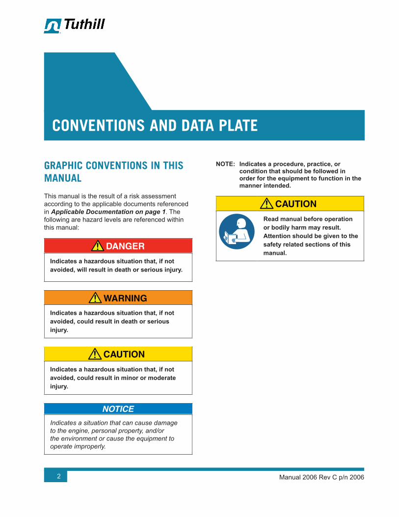
DANGER!Indicates a hazardous situation that, if not avoided, will result in death or serious injury.
WARNING!Indicates a hazardous situation that, if not avoided, could result in death or serious injury.
CAUTION!Indicates a hazardous situation that, if not avoided, could result in minor or moderate injury.
Indicates a situation that can cause damage to the engine, personal property, and/or the environment or cause the equipment to operate improperly.
OTE: N Indicates a procedure, practice, or condition that should be followed in order for the equipment to function in the manner intended.
CAUTION!Read manual before operation or bodily harm may result. Attention should be given to the safety related sections of this manual.
CONVENTIONS AND DATA PLATE
02

Manual 2006 Rev C p/n 2006 3
02Conventions and Data Plate
DATA PLATE
WARNING WARNING CAUTION CAUTION
http://www.tuthill.com
Hearing protection required.
Do not touch hot surfaces.
ASU eht ni edaM7396-528 )008(
READ INSTRUCTION MANUAL BEFORE OPERATION OR BODILY HARM MAY RESULT
Keep body & clothing away from machine openings.
Do not operate without guards in place.
REBMUN LAIRESREBMUN LEDOM
Tuthill Vacuum & Blower Systems4840 West Kearney Street
Springfield, Missouri USA 65803
YEARMAWP
MAX RPM
Figure 2-1 – General Operation and Symbols on Data Plate
The following information is contained on the data plate:
WARNING!Keep body & clothing away from machine.
During operation, keep body and clothing away from inlet and outlet of the blower.
WARNING!Do not operate without guards in place.
CAUTION!Hearing protection is required while the blower is in operation. Noise levels may reach as high as 81 dBA.
CAUTION!Do not touch hot surfaces.
The upper limit of the blower operation is 400°F (205°C). Do not touch the blower while it is in operation and assure blower is cool when not in operation.

Manual 2006 Rev C p/n 20064
02
Conventions and Data Plate
MODEL NUMBER: The specific model of the blower
SERIAL NUMBER: Unique to each blower
YEAR: Year of manufacture
MAWP: Maximum Allowable Working Pressure
The standard MAWP is per Table 4-2 – Maximum Operating Limits on page 9. The MAWP shall not be exceeded.

Manual 2006 Rev C p/n 2006 5
WARNING!The blower must be handled using an appropriate device such as a fork truck or appropriate lifting device. See Table 4-1 on page 8 for approximate weights. Care should be taken to assure blower does not over-turn during handling and installation.
LIFTING
03

Manual 2006 Rev C p/n 20066
Refer to specific data sheets for flow capacities and vacuum capacities.
OTE: N Refer to diagrams in this manual for proper rotation and orientation in inlet and discharge.
Tuthill Springfield model 4000 and 5500 Series rotary lobe blowers are positive displacement type blowers, whose pumping capacity is determined by size, operating speed, and differential pressure conditions. Blowers employ rotors rotating in opposite directions within a housing closed at the ends by end plates.
The inlet to the discharge is sealed with operating clearances that are very small. Internal lubrication is not needed, as there is no moving contact.
Clearances between the rotors during rotation are maintained by a pair of accurately machined helical timing gears, mounted on the two shafts extended outside the air chamber. The intermeshing rotary lobes are designed to rotate and trap air or gas between each rotor and the housing. As the rotor lobes rotate past the edge of the suction port, the trapped air or gas is essentially at suction pressure and temperature. Since the blower is a constant volume device, the trapped air remains at suction pressure until the leading rotor lobe opens into the discharge port. The close clearances between the rotors inhibit back slippage of the trapped volume from between the rotors, and the trapped volume is forced into the discharge piping. Compression occurs not internal to the blower but by the amount of restriction, either downstream of the blower
discharge port or upstream of the blower inlet port.
Figure 4-1 illustrates the air movement within the machine. In addition, the machine can operate in either direction.
Never attempt to control capacity by means of a throttle valve in the intake or discharge piping. This will increase the power load on the drive system, will increase operating temperatures, and can overload and/or seriously damage the blower. Likewise, if the possibility exists that flow to the blower inlet may be cut off during normal operation of a process, install an adequate vacuum relief valve. A pressure-type relief valve in the discharge line near the blower is also recommended for protection against cutoff or blocking in this line. Use check valves on each blower when more than one blower is connected to a discharge line.
When a belt drive is used, it is possible to adjust blower speed to obtain the desired capacity by changing the diameter of one or both sheaves, or by using a variable-speed motor pulley. In a direct-coupled arrangement, a variable-speed motor or transmission is required. Gas blowers can use bypasses, but some applications may require additional cooling. If there is a large volume of high-pressure air or gas downstream of the blower, a check valve in the piping downstream of the blower will protect the blower from overspeeding in a backward direction upon shutdown.
Consult a Tuthill Springfield sales professional if questions arise.
DESCRIPTION
04

Manual 2006 Rev C p/n 2006 7
04Description
INLET INLET INLET
DISCHARGE DISCHARGE DISCHARGE
Figure 4-1 – General Operation Principle
FLOW BY DIRECTION
WARNING!Refer to diagrams in this manual for proper rotation and orientation in inlet and discharge.
INTAKEINTAKE
DISCHARGE INTAKE
DISCHARGE
HORIZONTAL FLOWVERTICAL FLOW
DISCHARGE
INTAKE DISCHARGE
INTAKE
DISCHARGERIGHT DRIVE
CW ROTATIONLEFT DRIVE
CW ROTATIONLEFT DRIVE
CCW ROTATIONRIGHT DRIVE
CCW ROTATION
TOP DRIVECW ROTATION
TOP DRIVECCW ROTATION
BOTTOM DRIVECW ROTATION
BOTTOM DRIVECCW ROTATION
DISCHARGEINTAKE INTAKE
INTAKEDISCHARGE DISCHARGE
Figure 4-2 – Flow Direction by Rotation

Manual 2006 Rev C p/n 20068
04
Description
SPECIFICATIONS
MODEL
APPROXIMATE OIL CAPACITY APPROXIMATE VERTICAL FLOW WEIGHT
VERTICAL FLOW HORIZONTAL FLOWSTANDARD SINGLE
ENVELOPEDOUBLE
ENVELOPEGEAR (DRIVE) END
BACK END
GEAR (DRIVE) END
BACK END
3202
12 oz (0.35 L) 8 oz (0.24 L) 17 oz (0.50 L) 12 oz
(0.35 L)
100 lb (46 kg)
110 lb (50 kg)
115 lb (53 kg)
3204 120 lb (55 kg)
130 lb (59 kg)
135 lb (62 kg)
3206 130 lb (59 kg)
140 lb (64 kg)
145 lb (66 kg)
3210 165 lb (75 kg)
175 lb (80 kg)
180 lb (82 kg)
4006
24 oz (0.71 L) 24 oz (0.71 L) 14 oz (0.42 L) 14 oz
(0.42 L)
170 lb (77 kg)
180 lb (82 kg)
185 lb (84 kg)
4009 200 lb (91 kg)
210 lb (96 kg)
215 lb (84 kg)
4012 225 lb (182 kg)
235 lb (107 kg)
240 lb (109 kg)
5507
57 oz (1.7 L) 57 oz (1.7 L) 32 oz (0.95 L) 32 oz
(0.95 L)
400 lb (182 kg)
415 lb (189 kg)
420 lb (191 kg)
5511 460 lb (209 kg)
475 lb (216 kg)
480 lb (218 kg)
5514 500 lb (227 kg)
515 lb (234 kg)
520 lb (236 kg)
5516 540 lb (245 kg)
555 lb (252 kg)
560 lb (255 kg)
5518 580 lb (264 kg)
595 lb (270 kg)
600 lb (273 kg)
Table 4-1 – Specifications

Manual 2006 Rev C p/n 2006 9
04Description
MODEL MAXIMUM RPMMAXIMUM
PRESSURE DIFFERENTIAL
MAXIMUM VACUUMMAXIMUM
TEMPERATURE RISE
MAWP
3202
3600
15 psi (1,035 mbar) 15 inch-Hg (508 mbar) 280°F (156°C)
100 psi (6.9 bar)
3204 15 psi (1,035 mbar) 15 inch-Hg (508 mbar) 280°F (156°C)
3206 15 psi (1,035 mbar) 15 inch-Hg (508 mbar) 280°F (156°C)
3210 15 psi (1,035 mbar) 15 inch-Hg (508 mbar) 280°F (156°C)
4006 15 psi (1,035 mbar) 15 inch-Hg (508 mbar) 300°F (167°C)
4009 18 psi (1,241 mbar)* 17 inch-Hg (575 mbar) 360°F (200°C)*
4012 15 psi (1,035 mbar) 15 inch-Hg (508 mbar) 300°F (167°C)*
5507 18 psi (1,241 mbar)* 17 inch-Hg (575 mbar) 360°F (200°C)*
5511 17 psi (1,172 mbar) 17 inch-Hg (575 mbar) 360°F (200°C)*
5514 13 psi (896 mbar) 15 inch-Hg (508 mbar) 300°F (167°C)
5516 12 psi (827 mbar) 15 inch-Hg (508 mbar) 260°F (144°C)
5518 10 psi (690 mbar) 15 inch-Hg (508 mbar) 200°F (111°C)
* High-pressure option
Table 4-2 – Maximum Operating Limits

Manual 2006 Rev C p/n 200610
04
Description
WARNING!The maximum pressure differential is based on the difference between the inlet pressure and the outlet pressure. The maximum pressure differential shall not be exceeded. Exceeding the maximum pressure differential will cause serious damage to the equipment and could cause bodily injury.
WARNING!The maximum allowable working pressure (MAWP) is based on the absolute pressure of the blower housing and is NOT the maximum allowable pressure differential. Exceeding the MAWP will cause serious damage to the equipment and could cause bodily injury.
To permit continued satisfactory performance, a blower must be operated within certain approved limiting conditions. The manufacturer’s warranty is, of course, also contingent on such operation.
Maximum limits for pressure, temperature, and speed are specified in See Table 4-2 on page 9 for various blower sizes when operated under the standard atmospheric conditions. Do not exceed any of these limits.
Specially ordered blowers with nonstandard construction, or with rotor end clearances greater than shown in Assembly Clearances on page 39, will not have the operating limits specified here. Contact your Tuthill Springfield sales representative for specific information.
Special attention must be paid when a blower has a higher than standard ambient suction temperature. Special recommendations for operating parameters and/or additional cooling may be recommended. Consult the factory or local representative for appropriate information.

Manual 2006 Rev C p/n 2006 11
GENERAL
DANGER!The blower is not intended to be used with explosive products or in explosive environments. The blower is not intended to be used in applications that include hazardous and toxic gases. Consult the factory for support.
DANGER!It is the responsibility of the installer to assure that proper guarding is in place and compliant with all applicable regulatory requirements.
WARNING!The bare shaft blower can generate excessive noise. Methods to reduce the noise levels by installing inlet and outlet silencers will be required. Even with inlet and outlet silencers, hearing protection will be required.
WARNING!Customers are warned to provide adequate protection, warning and safety equipment necessary to protect personnel against hazards in the installation and operation of this equipment in the system or facility.
WARNING!The standard MAWP is per Table 4-2. The MAWP shall not be exceeded unless specific factory testing of the pressure containing components of the blower has been performed.
WARNING!Table 4-2 states the maximum operating speed in RPM (rotations per minute) and maximum temperature. Do not exceed these limits. The installation of the blower shall take these critical operating parameters into account and adequate control features implemented.
INSTALLATION
05
Manual 2006 Rev C p/n 200612
05
Installation
WARNING!Upon completion of the installation, and before applying power, rotate the drive shaft by hand. It must move freely. If it does not, look for uneven mounting, piping strain, excessive belt tension or coupling misalignment or any other cause of binding. If blower is removed and still does not move freely, check inside the blower housing for foreign material.
Remove the protective covers from the shaft and inspect for damage.
Carefully check to ensure that no transit damage has been sustained. If damage has occurred from shipment, file a claim with the carrier immediately. Preserve the shipping container for inspection by the carrier.
In the event that your unit sustains damage while being shipped to your facility, do not return it to the factory without first obtaining shipping instructions from us.
Do not remove protective covers and plugs until the connections are complete. Mount the blower on a flat, level surface. Use a baseplate that is rigid, solidly supported, and structurally sound. Shim under the legs where necessary so that each leg of the blower supports an equal share of the blower weight. This is necessary to prevent twisting of the blower. Make sure the feet rest evenly on the mounting surface before fastening down. Twisting or cramping the blower during mounting will cause rotor contact and binding during operation, resulting in a condition called “soft foot.” See Soft Foot on page 14 for further details and preventative measures.
A blower that is factory-mounted on a base should not require such adjustments. However, since the assembly can become twisted in shipping or installation, check for soft foot after installing the
base. Shims may be needed for alignment. Loosen the foot hold-down screws to check foot contact with the mounting surface. Mount the base on a solid foundation or heavy flooring, using shims as necessary at bolting points to prevent warping the assembly.
Transmission of small operating vibrations to a support structure may be objectionable in some applications. Use of vibration isolators or vibration-absorbing materials can be effective in overcoming this transmission. To avoid causing distortion, apply the treatment under the common motor/blower base or mounting plate rather than directly under the feet alone.
Make sure piping is accurately squared with the blower and supported independently. Stress imparted from incorrectly aligned piping or mounting will create problems with bearing and seal life, possibly leading to premature internal contact. The blower should sit stress free and evenly on its supporting surface. Take care to evenly tighten the mounting bolts to avoid imparting undue stress into the blower. Stress can be checked in a free state with feeler stock or verified on a previously installed blower with the aid of a dial indicator. Spring or gap should be less than 0.002 in. (0.05 mm).
Use only clean, new pipe and make certain it is free of scale, cuttings, weld beads, dirt, or any other foreign material. To guard against damage to the blower, make sure that an inlet filter is used. Clean the filter of collected debris after 3 hours of operation and periodically thereafter. See Piping Connections on page 17 for additional details.
Figure 5-1 shows a typical complete installation of the blower and accessories. Note the absence of throttle or shut-off valves in both discharge and intake piping. If it is possible for airflow to be cut off in either line, add a pressure and/or vacuum relief valve. In some installations, it may be desirable to use only an inlet silencer-cleaner supported directly from the blower connection. Keep the weight of accessories and piping to a minimum to prevent blower casing distortion. If the weight exceeds 10% of blower weight, support the components independently of the blower and connect them with a flexible hose or connectors. The approximate weight of the blower is listed in Table 4-1 on page 8.

Manual 2006 Rev C p/n 2006 13
05
Installation
AIR FILTER
PRESSURERELIEF VALVE
CHECK VALVE
FLEX CONN.
PRESSURE GAUGE DISCHARGESILENCER
INTAKE SILENCER
FLOW
FLOW
Figure 5-1 – Typical Blower Installation
A blower may be driven by direct-coupling to the driver or by V-belt drive for the purpose of obtaining other speeds within the approved range. See Motor Drives on page 19 for more information.
Blowers from Tuthill Springfield are internally and externally treated after factory assembly and testing to protect against rusting in normal atmospheric conditions prior to installation. The maximum period of internal protection is considered to be 6 months under average conditions, provided closing plugs and seals are not removed. Protection against chemical or salt-water atmosphere is not provided. Avoid opening the blower until ready to begin installation, as protection will be quickly lost due to evaporation. For recommended preparations for long-term storage (longer than 6 months), see Long-Term Storage on page 30.
Location
Install the blower in a room or outdoor area that supplies adequate space and lighting for routine maintenance. Make sure that indoor installation areas are well ventilated and kept as cool as possible, because operating the blower at elevated temperatures can result in nuisance overload or temperature shutdowns. An unprotected outdoor installation is satisfactory only when correct lubrication for the expected temperatures is provided. See Recommended Lubricants on page 35.
Blower Air Intake
To minimize maintenance, supply the blower with the cleanest air possible. The air must not contain any flammable or toxic gases, as the blower will concentrate these gases. This could result in damage to the blower and surrounding property and lead to personal injury or death. Do not block or restrict the opening of the blower, as the motor could overheat and fail.
Do not use blowers on explosive or hazardous gases. Do not exceed the limits described in Table 4-2 on performance criteria such as pressure differential, running speed, and discharge temperature.
If it is necessary to take air from a remote source, such as in a vacuum application, make sure the diameter of the piping is at least equal to the diameter of the blower inlet. For distances greater than 20 ft (6 m), enlarge the pipe diameter to reduce inlet restriction. Excessive restriction will reduce the efficiency of the blower and elevate its discharge temperature. The piping used should also be corrosion-resistant and free of scale and dirt. Keep the inlet covered to keep out foreign objects and rain. Vacuum kits are available.

Manual 2006 Rev C p/n 200614
05
Installation
Soft Foot
Soft foot is a condition in which one of the blower feet does not sit flat on the base. Soft foot is usually due to irregularities in the surface to which the blower is mounted. When the bolt on the foot gets tightened, a slight distortion occurs that can affect bearing and seal life as well as internal contact between parts.
ANGULARSOFT FOOT
PARALLELSOFT FOOT
Figure 5-2 – Illustrations of Soft Foot
1. Place the blower on the base.
2. Check each foot for gaps between the foot and base (soft foot). Shim as necessary to fill the gap within 0.002 in. (0.05 mm). Figure 5-2 shows the two most common types of soft foot conditions. If either type is present at a measurement of more than 0.003 in. (0.076 mm), the blower may fail prematurely.
3. Tighten all bolts.
4. Mount a dial indicator on the base contacting one foot at 12 o’clock position.
5. Loosen the bolt on that foot. Observe indicator travel and add shims as needed to reduce “spring” to less than 0.002 in. (0.05 mm). Repeat steps 4 and 5 on the remaining feet.
SAFETY
Tuthill Springfield recommends the use of relief valves to protect against excessive pressure or vacuum conditions. Test these valves at initial start-up to be sure they are properly adjusted to relieve at or below the maximum pressure differential rating of the blower.
DANGER!It is the responsibility of the installer to assure that proper guarding is in place and compliant with all applicable regulatory requirements.
DANGER!Internal and external rotating parts of the blower and driving equipment can produce serious physical injuries. The blower should never be run with the inlet or discharge piping removed. If it becomes necessary to inspect the rotating parts of the blower or to change V-belts, be absolutely sure that all power to the motor controls has been shut off, the motor controls are locked out, and properly tagged before proceeding.
Manual 2006 Rev C p/n 2006 15
05
Installation
DANGER!Assure that properly sized vacuum breaks/relief valves are used on the inlet side of the blower. Also assure that properly sized pressure relief valves are used on the outlet of the blower. The sizing shall be such to assure that the proper flow can be achieved without exceeding the rated vacuum and pressure ratings.
DANGER!Blower housing and associated piping or accessories may become hot enough to cause major skin burns on contact.
WARNING!Use lock out/tag out procedures to disable the electrical energy source before any service or work is done on the blower.
WARNING!Avoid extended exposure in close proximity to machinery with high intensity noise levels. Wear adequate ear protection.
OTE: N Use proper care and good procedures in handling, lifting, installing, operating, and maintaining the equipment.
LUBRICATION
Every blower from Tuthill Springfield is factory-tested, oil-drained, and shipped dry to its installation point. Fill both independent oil reservoirs to the proper level before operation. Oil reservoirs are under the vacuum.
Shaft bearings at the gear end of the blower are splash-lubricated by one or both gears dipping into an oil reservoir formed in the gear end plate and cover. Shaft bearings at the drive end of the blower are lubricated by a slinger assembly dipping into an oil reservoir. Before starting the blower, fill the oil sumps as described in Filling Procedure on page 16.
Add oil to the blower in the quantity listed in Table 4-1 on page 8. Make sure oil level is maintained within the notched area of the sight glass. See Figure 5-3. Lower drive blowers have “bull’s eye” type oil level gauges. Maintain oil levels at the center of the glass.
WARNING!Never attempt to change or add lubrication while the blower is running. Failure to heed this warning could result in damage to the equipment or personal injury. Oil must be checked when the blower is NOT running.
WARNING!Properly dispose of the spent lubricants. Refer to the manufacturer of the lubricant and any regulations to assure proper and safe disposal.
WARNING!Do not start the blower until you are sure oil has been put in the gear housing and rear cover. Operation of the blower without proper lubrication will cause the blower to fail and void the warranty.

Manual 2006 Rev C p/n 200616
05
Installation
Assure oil is compatible with copper/yellow metals (if equipped with cooling coils).
See Table 4-1 for oil capacities.
Filling Procedure
See Recommended Lubricants on page 35 for suggested lubricants and grease.
1. Remove the fill plugs or breathers from both gear end and drive end plates.
2. Slowly pour oil through the fill until oil appears in the oil sight glass. Bring the oil level to the center of the sight glass.
3. Verify oil level is at proper level in both gear end and drive end sight glasses.
4. Replace the fill plugs or breathers that were removed in step 1.
HORIZONTAL FLOW VERTICAL FLOW
END END
SIDE SIDE
MAGNETICDRAIN PLUG
(1) EAEND PLATE
MAGNETICDRAIN PLUG
(1) EAEND PLATE
OIL LEVELGAUGE(1) EAEND COVER
OIL LEVELGAUGE(1) EAEND PLATE
BREATHER& OIL FILL(1) EAEND PLATE
BREATHER& OIL FILL(1) EAEND PLATE
Figure 5-3 – Oil Fill, Drain Connections, and Oil Level Gauges
Frequently Asked Questions Regarding Lubrication
What is the functional detriment if the “wrong oil” is used?
The lubricant is selected based on bearing speed, gear speed, and operating temperature. If the lubricant is too light, it increases wear by not separating the sliding surfaces and it will not remove the heat adequately. If the lubricant is too thick, the drag in the bearings is increased, causing

Manual 2006 Rev C p/n 2006 17
05
Installation
them to run hotter. Thicker lubricant will not flow as readily into the gears and it will reduce the available backlash. Lubricants at our conditions are incompressible.
What is the functional detriment if the oil is not serviced?
If the lubricant is not serviced at the proper interval, the shearing action in the bearing and the gears will begin to take its toll and the lubricant will thicken. The blower will run hotter and the wear on moving parts will increase. The lubricant will generally appear dirtier, caused by material rubbing off the components. The lubricant will discolor because of overheating. An indicator of the breakdown of a lubricant is the increase in the Total Acid Number (TAN) and a change of 10 percent in the base viscosity.
Several things are happening as the lubricant goes through the blower. First, it is absorbing frictional energy in the form of heat. This heat has to be dissipated through either surface contact with cooler materials or in a rest volume of lubricant. While reducing the friction, the lubricant is also going through a shearing process and the molecular structure is broken down.
The result is that the lubricant will begin to thicken because of the shorter molecular chains and the drop out of additive packages. The thickened lubricant will cause more drag, increasing the friction and heat and further degrading the lubricant.
Operation of the blower (environment, run time, speed, and pressure) has a direct effect on duty cycles. The published cycles are based on worst-case conditions.
Hazards Associated With Breakdown or Ignition of Lubrication
DANGER!There is a risk associated with the lubrication media breaking down and resulting in a hazardous fluid or vapor. There may also be a hazard associated with the ignition of the lubrication media. Refer to the lubrication manufacturer’s applicable instruction for safety precautions.
PIPING CONNECTIONS
WARNING!Pipe loading on the blower should be negligible as pipe loading can cause distortion of the blower. Use proper supports and pipe hangers to assure that there is no loading.
Remove the protective covers from the inlet and outlet ports and inspect for dirt and foreign material.
Inlet and outlet connections on all blowers are large enough to handle maximum volume with minimum friction loss. Maintain same-diameter piping. Do not support silencers by the blower. Avoid stress loads and bending moments.

Manual 2006 Rev C p/n 200618
05
Installation
Be certain all piping is clean internally before connecting to the blower. Place a 16-mesh wire screen backed with hardware cloth at or near the inlet connections for the first 50 hours of use until the system is clean. Clean the screen after 3 hours of operation and completely discard it once the system is clean, as it will eventually deteriorate and small pieces going into the blower can cause serious damage. A horizontal or vertical airflow piping configuration is easily achieved by rearranging the mounting feet position.
Hazards Associated With Hazardous Process Fluids
DANGER!It shall be the responsibility of the installer to ensure that piping is adequate, sealing between pipe joints is adequate for the process fluids and proper process and pressure protection devices are in place. It is also the responsibility of the installer to assure that process gasses are not vented in a manner that would be hazardous.
Refer to the manufacturer of the process media to assure that proper safety precautions are in place.
Blockage or Restriction
WARNING!Damage to the blower could occur if there is blockage in the inlet or outlet ports or piping. Care should be taken when installing the blower to assure that there are no foreign objects or restrictions in the ports or piping.
COOLING COILS (OPTIONAL)
CAUTION!If the blower is to be located outdoors or in a building where the temperature surrounding the blower or the water supply and return piping can fall below 35°F (2°C), then care must be taken to ensure that the water (or other cooling liquid) does not freeze and cause damage. Cooling coils must be drained of liquid during downtime unless a recirculating unit using a glycol mixture has been installed.
Water cooled end plates are discontinued. Consult factory for connection details.
Units are never shipped from the manufacturer with liquid in the end plates or cooling coils.
Blowers supplied with coiling coils can be identified by the hose that connects the top of the gear (drive) end cover to the bottom of the free (non-drive) end cover. See Figure 5-4 and Figure 6-1 for details. Tuthill Springfield recommends water cooling for blowers in applications where the blower operates with discharge temperatures of 250°F (120°C) for 4 hours or more per day. Water cooling reduces oil temperature and improves oil viscosity for better lubrication. A water flow of 0.5 – 1.0 GPM (1.9 – 3.8 L/min) is generally sufficient to maintain oil temperatures of 150°F (65°C) or below. Do not allow water pressure to exceed 75 psig (510 kPa g).

Manual 2006 Rev C p/n 2006 19
05
Installation
COOLING WATER CONNECTIONS AND SPECIFICATIONS — COOLING COILS (OPTIONAL)
WARNING!The cooling water pressure shall not exceed 75 psig (5.17 bar g).
Establish proper gap between coupling halves according to the coupling manufacturer’s instructions with the motor armature. Proper gap will minimize the chance of end thrust on the blower shaft. Re-align and grease all direct-coupled base-mounted blowers after field installation.
MOTOR DRIVES
Figure 5-4 – Water Cooling Connections
Two drive connections commonly used are direct drive and V-belt drive.
Direct Coupled
When installing the motor directly to the blower, align the shafts to the coupling according to the coupling manufacturer’s instructions. Blowers shipped with the motor directly coupled and mounted on a common base have been aligned prior to shipment. Further alignment is not normally necessary, but be sure to check the alignment and make adjustments if necessary prior to starting the blower.
Coupling halves must correctly fit the blower and drive shafts so that only light tapping is required to install each half. The two shafts must be accurately aligned. A direct-coupled blower and motor must be aligned with the two shafts having no more than 0.005 in. (13 mm) Total Indicator Reading (TIR). Make sure the face is aligned within 0.002 in. (0.05 mm).
Establish proper gap between coupling halves according to the coupling manufacturer’s instructions with the motor armature. Proper gap will minimize the chance for end thrust on the blower shaft. Re-align and grease all direct-coupled base-mounted blowers after field installation.

Manual 2006 Rev C p/n 200620
05
Installation
V-Belts
If the motor and blower are V-belt connected, the sheaves on both the motor and blower shafts should be as close to the shaft bearings as possible. Blower sheave is not more than 1/4 in. (6.5 mm) from the blower drive end cover. The drive sheave is as close to the driver bearing as possible. Take care when installing sheaves on the blower and motor shafts. Make sure the face is accurately in line to minimize belt wear.
Adjust the belt tension to the manufacturer’s specifications using a belt tension tester. Check new belts for proper tension after 24 hours of run time. When manufacturer data is not available, industry guidelines recommend 1/64 in. deflection for each inch of span (0.157 mm deflection per centimeter of span) at 8 – 10 lb (3.6 – 4.5 kg) of force in the center of the belt.
Insufficient tensioning is often indicated by slipping (squealing) at start-up. Do not use belt dressing on V-belts. Keep sheaves and V-belts free of oil and grease. Remove tension from belts if the drive is to be inactive for an extended period of time. For more specific information, consult the drive manufacturer. In a V-belt drive, the blower sheave must fit its shaft accurately, run true, and be mounted as close to the bearing housing as possible to minimize bearing loads.
A tight or driving fit will force the drive shaft out of its normal position and cause internal damage. A loose fit will result in shaft damage or breaking. Make sure the motor sheave fits correctly and is properly aligned with the blower sheave.
Adjust the motor position on its sliding base so that belt tension is in accordance with drive manufacturer’s instructions. Always avoid excessive belt tension. Recheck tension after the first 10 hours of operation and periodically thereafter to avoid slippage and loss of blower speed.
Too Tight
Slight Bow Too Loose
20/64” = 5/16” (8 mm)
20” (50.8 cm)
8-10 lbs.(3.6-4.5 kg)
Figure 5-5 – General appearance of a V-belt drive
Too Tight
Slight Bow Too Loose
20/64” = 5/16” (8 mm)
20” (50.8 cm)
8-10 lbs.(3.6-4.5 kg)
Figure 5-6 – Setting of proper tension for a V-belt drive
Check the blower after installation and before applying power by rotating the drive shaft by hand.
If the drive shaft does not rotate freely:
• Look for uneven mounting, piping strain, excessive belt tension, or coupling misalignment
• Check the blower to make sure oil was added to the reservoirs
Setting V-Belt Tension
Proper belt tension is essential to long blower life. Figure 5-5, Figure 5-6, and the following procedure are provided to aid in field-adjusting V-belts (when the blower is so equipped) for maximum performance. A visual inspection of the V-belt drive should yield the appearance shown in Figure 5-5.
Factors outside the control of the belt tensioning system used on an individual blower package assembly, such as environmental factors and quality of the belts installed, may contribute to decreased belt life. Such factors can cause wear of the belts beyond the ability of the tensioning system to compensate.

Manual 2006 Rev C p/n 2006 21
05
Installation
As such, it is recommended to check belt tension monthly and make any manual adjustments found necessary.
1. Turn off and lock out power.
2. Remove the belt guard fasteners (if equipped).
3. Remove the belt guard.
4. Check and adjust the belt tension as necessary. Tension should be 1/64 in. deflection per inch of span (0.157 mm deflection per centimeter of span) between
sheaves, with 8 – 10 lb (3.6 – 4.5 kg) force applied at the center point of the top section of belt.
5. Install the belt guard, making sure that all drive components are free of contact with the guard.
6. Install the belt guard fasteners that were removed in step 2.
7. Unlock the power and start the blower.
8. Resume normal operation.
V-Belt Troubleshooting
PROBLEM POSSIBLE CAUSES SOLUTION
Belts slip (sidewalls glazed) Not enough tension Replace belts; apply proper tension.
Drive squealsShock load Apply proper tension.Not enough arc of contact Increase center distance.Heavy starting load Increase belt tension.
Belt(s) turned over
Broken cord caused by prying on sheave Replace set of belts and install correctly.
Overloaded drive Redesign drive.Impulse loads Apply proper tension.Misalignment of sheave and shaft Re-align drive.Worn sheave grooves Replace sheaves.
Excessive belt vibration
Check drive design.
Check equipment for solid mounting.
Consider use of banded belts.Mismatched belts New belts installed with old belts Replace belts in matched sets only.
Breakage of belt(s)
Shock loads Apply proper tension; recheck drive.
Heavy starting loadsApply proper tension; recheck drive.
Use compensator starting.Belt pried over sheaves Replace set of belts correctly.Foreign objects in drives Provide drive guard.

Manual 2006 Rev C p/n 200622
05
Installation
PROBLEM POSSIBLE CAUSES SOLUTION
Rapid belt wear
Sheave grooves worn Replace sheaves.Sheave diameter too small Redesign drive.Mismatched belts Replace with matched belts.Drive overloaded Redesign drive.Belt slips Increase tension.Sheaves misaligned Align sheaves.Oil or heat condition Eliminate oil. Ventilate drive.
Motor and Electrical Connections
WARNING!The motor and connections shall be protected to assure that product and environmental condensation does not come in contact with the electrical connections.
It is the responsibility of the installer to assure that the motor is in compliance with the latest edition of IEC 60204-1 and all electrical connections are performed per IEC 60204-1, this includes overcurrent protection.
Wire the motor and other electrical devices, such as solenoid valves and temperature switch, to the proper voltage and amperage as indicated on the nameplate of the component being wired. Turn the blower by hand after wiring is completed to determine that there are no obstructions and that the blower turns freely. Then, momentarily start the blower to check the direction of rotation. Figure 4-2 shows direction of airflow in relation to rotor rotation. The airflow direction can be reversed by reversing the appropriate motor leads.

Manual 2006 Rev C p/n 2006 23
GENERAL
DANGER!The blower is not intended to be used with explosive products or in explosive environments. The blower is not intended to be used in applications that include hazardous and toxic gases. Consult the factory for support.
WARNING!Do not operate without guards in place.
WARNING!Maximum operating speed: Table 4-2 states the maximum operating speed in RPM (rotations per minute), the maximum pressure differential, maximum vacuum and maximum temperature rise. Do not exceed these limits.
Before starting the blower for the first time under power, recheck the installation thoroughly to reduce the likelihood of difficulties. Use the following checklist as a guide, but consider any other special conditions in your installation.
1. Be certain no bolts, rags, or dirt have been left in blower.
2. Be certain that inlet piping is free of debris. If an open outdoor air intake is used, be sure the opening is clean and protected by an inlet filter. This also applies to indoor use.
3. If installation is not recent, check blower leveling, drive alignment, belt tension, and tightness of all mounting bolts.
4. Be certain the proper volume of oil is in the oil reservoir chambers.
5. Be certain the driving motor is properly lubricated and connected through suitable electrical overload devices.
6. With electrical power off and locked out to prevent accidental starting, rotate the blower shaft several times by hand to make sure the blower is rotating freely. Unevenness or tight spots are indicators of a condition that should be corrected before progressing.
7. Check motor rotation by momentarily pushing the START button and then checking the flow direction of the blower. Reverse the motor connections if the flow is in the wrong direction.
OPERATION
06

Manual 2006 Rev C p/n 200624
06
Operation
Carry out initial operation under “no load” conditions by opening all valves and venting the discharge to the atmosphere, if possible. Then, start the motor briefly, listen for unusual noises, and make sure the blower coasts freely to a stop. If no problem appears, repeat this check and let the motor run slightly longer. If any questions exist, investigate before proceeding.
Assuming all tests are satisfactory, the blower will now be ready for continuous full-load operation. During the first several days, check periodically to make sure all conditions remain acceptable and steady. These checks may be particularly important
if the blower is part of a process system where conditions may vary. At the first opportunity, stop the blower and clean or remove the inlet filter. Also recheck leveling, coupling alignment or belt tension, and mounting bolts for tightness.
START-UP CHECKLIST
It is recommended that these start-up procedures be followed in sequence and checked off ( ) in the boxes provided in any of the following cases.
• During initial installation• After any shutdown period
• After maintenance work has been performed• After blower has been moved to a new location
DATES CHECKED:
Check the unit for proper lubrication. Proper oil level is critical. See Lubrication on page 15. See Recommended Lubricants on page 35 for information on acceptable lubricants for the product.
Check the V-belt drive for proper belt alignment and tension.
Carefully turn the rotors by hand to be certain they do not bind.
WARNING!Disconnect power. Make certain power is off and locked out before touching any rotating element of the blower, motor, or drive components.
“Bump” the unit with the motor to check rotation (counterclockwise when facing the shaft) and to be certain it turns freely and smoothly.
Start the unit and operate it for 30 minutes at no load. During this time, feel the cylinder for hot spots. If minor hot spots occur, see Troubleshooting on page 32 .
Apply the load and observe the operation of the unit for 1 hour.
If minor malfunctions occur, discontinue operation and see Troubleshooting on page 31.

Manual 2006 Rev C p/n 2006 25
06
Operation
OPERATING
The upper temperature limit for blower operation is measured in the exhaust gas stream with a low-mass thermocouple. When this temperature limit switch is installed, as the temperature exceeds the predetermined temperature, the blower motor will stop and cannot be restarted until the temperature drops below the trip setting of the temperature switch.
DANGER!The blower is not intended to be used with explosive products or in explosive environments. The blower is not intended to be used in applications that include hazardous and toxic gases. Consult the factory for support.
WARNING!Physical harm may occur if human body parts are in contact or exposed to the process vacuum. Assure that all connections are protected from human contact.
WARNING!If rated vacuum or pressure levels are exceeded, process fluids will migrate to other parts of the blower and system.
CAUTION!Do not touch hot surfaces.
Do not touch the blower while it is in operation and assure blower is cool when not in operation.
CAUTION!Use of a thermowell insulates the thermocouple. Invalid and delayed readings will result. This can result in ineffective protection devices.
The upper temperature limits are not intended for continuous operation. Consult with factory for detailed information assistance.
CAUTION!Do not stop the blower if there are high outlet pressures in the outlet piping. Unload the outlet piping prior to shutting down the blower.
Stop the blower by turning off the motor. Isolate the blower from the vacuum system and vent the blower to the atmosphere. Turn off the cooling water, if the blower is water cooled. Stop the backing pump. See the component instruction manual.
METHANE GAS APPLICATIONS
Some sewage gases will adhere to the rotors in a gas blower. If enough sludge from the gas being pumped builds up on the rotors, it destroys the clearances between the rotors. The build-up can cause the blower to clatter and eventually freeze up when the rotors no longer have clearance to turn. This can be easily prevented by periodically flushing the blower with a mixture of 75% kerosene or fuel oil and 25% lubricating oil. The kerosene or fuel oil dissolves the sludge build-up and the lubricating oil coats the rotors to slow the build-up.

Manual 2006 Rev C p/n 200626
06
Operation
Inject the mixture on the inlet side through a valve set to feed 1 gal (3.8 L) of mixture in 15 – 20 minutes. On blowers that are regularly flushed, flushing once a week is sufficient. If the blower is dirty, flush it daily until the hard build-up is removed and then move to a weekly flushing cycle. In very dirty gas installations, vary the cycle to meet the demand.
FLUSHINGFLUID
CONTROLVALVE
Figure 6-1 – Flushing
WATER-INJECTED BLOWERS
Water injected into the inlet of a blower operating on vacuum service will cool the blower. The water absorbs the heat of compression as it passes through the blower along with the air/gas being compressed. A blower cooled in this manner can operate safely at higher vacuums or higher inlet temperatures than an uncooled blower.
The amount of water required depends on the inlet air/gas temperature, inlet vacuum, water temperature, and maximum discharge temperature desired. Check with the factory or sales representative for more guidance.
Operation
1. Check the oil level in the sight glass of the blower and make sure all fittings are tight.
2. Check the water injection system to make sure water is available.
3. Operate the blower dry for 3 minutes at no load to check for correct rotation and smooth operation.
4. Turn the water on and adjust the flow as recommended for the individual blower. Make sure the water discharges freely from the outlet piping.
5. Apply vacuum and observe operation at the desired inlet condition.
Shutdown
It is possible to shut down the blower for brief periods by relieving the inlet vacuum, shutting off the water, and then stopping the blower.
To avoid rusting during a slightly longer shutdown period, operate the blower under a partial vacuum without the water injection, allowing the blower to heat within safe limits. The heat will tend to drive off residual moisture.
For extended shutdown, oil may be injected into the inlet of the heated blower just prior to shutting down the blower. The oil will provide a protective coating on the internal components. Make sure the water is completely shut off after shutdown.
Special coatings or platings are available to minimize rusting or corrosion in applications where blowers can remain wet.
Always use vertical-flow blowers with two-lobed, plugged rotors. Always orient the system with the blower intake at the top and discharge at the bottom.
Manual 2006 Rev C p/n 2006 27
06
Operation
CAUTION!Water injection can cause lime build-up on rotors. Check water supply for hardness. The use of water softeners, other chemicals, or distilled water may be necessary to prevent or remove this build-up. However, due to the wide variations in mineral content, pH, and chemical content of water that can be injected, Tuthill Springfield cannot be responsible for damage which may result should this build-up occur. Units should be inspected regularly to determine any problems.
For liquid injection other than water, consult the factory.
RECOMMENDED SHUTDOWN PROCEDURE TO MINIMIZE RISK OF FREEZING OR CORROSION
When an air piping system has high humidity or moisture, water condensation can occur after the blower is shut down and it begins to cool. Condensation creates an environment favorable to corrosion of the iron internal surfaces and to ice formation in cold weather. Both conditions can close the operating clearances, causing the blower to fail upon future start-up.
The following shutdown procedure minimizes the risk of moisture condensation, corrosion, and freezing.
Care must be taken not to overload or overheat the blower during this procedure.
1. Isolate the blower from the moist system piping, allowing the blower to intake atmospheric air. Operate the blower under a slight load, allowing the blower to heat within safe limits. The heat generated by the blower will quickly evaporate residual moisture.
2. For carpet cleaning applications, after the work is completed, allow the blower to run 3 – 5 minutes with the suction hose and wand attached. The suction hose and wand will provide enough load to the blower to evaporate the moisture quickly.
3. For extended shutdown, inject a small amount of a light lubricating oil such as 3-in-One® or a spray lubricant such as WD-40® into the inlet of the blower just before shutdown (3-in-One and WD-40 are registered trademarks of WD-40 Company). The lubricant will provide an excellent protective coating on the internal surfaces. If using a spray lubricant, take care to prevent the applicator tube from getting sucked into the blower. The applicator tube will damage the blower, likely to a degree where repair would be required.
4. If the blower is being taken out of commission for an extended period of time, see Long-Term Storage on page 30.
Manual 2006 Rev C p/n 200628
GENERAL
Regular inspection of the blower and its installation, along with complete checks on operating conditions, will pay dividends in added life and usefulness. Also, service the drive per the manufacturer’s instructions and lubricate the coupling or check the belt drive tension. Use thermometers and gauges to make sure that blower operating temperature and pressure remain within allowed limits.
DANGER!The blower and parts may contain hazardous media. Assure that pump and parts are evacuated of hazardous media prior to servicing.
CAUTION!The electrical service must be isolated and de-energized prior to maintenance. Apply appropriate procedures to assure electrical supply is de-energized and cannot be inadvertently energized during maintenance.
Assure piping and product is isolated prior to maintenance of blower. Apply appropriate procedures to assure piping and product is isolated and that inadvertent opening of valves cannot occur during maintenance.
CAUTION!During routine maintenance, inspect and assure that guards are in place and secure.
Pay special attention to lubrication of timing gears and bearings according to the information in Lubrication on page 15.
When a blower is taken out of service, it may require internal protection against rusting or corrosion. The need for such protection must be a matter of judgment based on existing conditions as well as length of downtime. Under atmospheric conditions producing rapid corrosion, protect the blower immediately. See Long-Term Storage on page 30.
REGULAR MAINTENANCE
A well-designed maintenance program will add years of service to the blower.
Check a newly installed blower frequently during the first month of operation, especially lubrication. With the blower at rest, check the oil level in both the gear (drive) end and free (non-drive) end of the blower and add oil as needed. Complete oil changes are recommended every 1,000 - 1,200 operating hours, or more frequently depending on the type of oil and operating temperature. Also change the oil more frequently if pumping corrosive vapors or where excessive operating temperatures are encountered. The following is recommended as a minimum maintenance program.
MAINTENANCE
07

Manual 2006 Rev C p/n 2006 29
07Maintenance
DAILY WEEKLY MONTHLY
1. Check and maintain oil level, and add oil as necessary.
2. Check for unusual noise or vibration (See Troubleshooting on page 32).
1. Clean all air filters. A clogged air filter can seriously affect the efficiency of the blower and cause overheating and oil usage.
2. Check the relief valve to make sure it is operating properly.
1. Inspect the entire system for leaks.
2. Inspect the condition of the oil and change if necessary.
3. Check drive belt tension and tighten if necessary.
Oil levels should be checked every 24 hours of operation.
Proper oil drain schedules require oil be changed before the contaminant load becomes so great that the lubricating function of the oil is impaired or heavy disposition of suspended contaminants occurs. To check the condition of the oil, drain a sample into a clean container and check for the presence of water or solids. Slight discoloration of the oil should not necessitate an oil change.
SPARE PARTS
Should adjustments or replacement be needed, repairs can often be performed locally as described in this manual after obtaining the required parts. Personnel should have a good background of mechanical experience and be thoroughly familiar with the procedures outlined in this manual. For major repairs not covered in this manual, contact the nearest Tuthill Springfield service representative.
When ordering parts, supply the blower nameplate information, as well as the item number and parts description as per the parts lists and assembly drawings. Repair kits are available for all models. These kits contain all the seals, bearings, O-rings, locks, and special retaining screws necessary for an overhaul. For convenience when ordering parts, complete the Operating Data Form included on the inside, back cover of this manual.
In developing a stock of spare parts, consider the following factors:
• The degree of importance in maintaining the blower in a “ready” condition
• The time lag in parts procurement
• Cost
• Shelf life (seals and O-rings)
FACTORY SERVICE AND REPAIR
With proper care, Tuthill Springfield blowers will give years of reliable service. The parts are machined to close tolerances and require special tools by mechanics who are skilled at this work. Should major repairs become necessary, contact the factory for the location of the nearest service facility.
Current regulations require Material Safety Data Sheet to be completed and forwarded to Tuthill Corporation on any unit being returned for any reason which has been handling or involved with hazardous gases or materials. This is for the protection of the employees of Tuthill Corporation who are required to perform service on this equipment. Failure to do so will result in service delays.
Manual 2006 Rev C p/n 200630
07
Maintenance
When returning a blower to the factory for repair under warranty, please note the factory will not accept any unit that arrives without authorization. Contact Customer Service for return authorization.
LONG-TERM STORAGE
Any time the blower will be stored for an extended period of time, make sure it is protected from corrosion by following this procedure:
1. Spray the interior (lobes, housing, and end plates) with rust preventative. Repeat as conditions dictate and on an at least a yearly basis.
2. Fill both end covers completely full of oil.
3. Firmly attach a prominent tag stating that the end covers are full of oil and must be drained and refilled to proper levels before start-up.
4. Apply a rust-preventative grease to the drive shaft.
5. Spray all exposed surfaces, including the inlet and discharge flanges, with rust preventative.
6. Seal the inlet, discharge, and vent openings. It is not recommended that the blower be set in place, piped to the system, and allowed to remain idle for a prolonged amount of time. If any component is left open to the atmosphere, the rust preventative will escape and lose its effectiveness.
7. During storage, make sure the blower does not experience excessive vibration.
8. Attach a desiccant bag to one of the covers to prevent condensation from occurring inside the blower. Make sure any desiccant bag (or bags) is attached to the covers so that they will be removed before start-up of the blower.
9. Store the blower in an air conditioned and heated building if possible. If air conditioned and heated storage is not possible, make conditions as dry as possible.
10. If possible, rotate the drive shaft by hand at least monthly to prevent seals from setting in one position.

Manual 2006 Rev C p/n 2006 31
Although Tuthill Springfield blowers are well designed and manufactured, problems may occur due to normal wear and the need for readjustment. The following chart lists symptoms that may occur along with probable causes and remedies.
SYMPTOM PROBABLE CAUSE REMEDIES
Loss of oil
Gear housing not tightened properly Tighten gear housing bolts.
Lip seal failure Disassemble and replace lip seal.
Insufficient sealant Remove gear housing and replace sealant.
Loose drain plug Tighten drain plug.
Excessive bearing or gear wear
Improper lubrication Correct oil level. Replace dirty oil. See Lubrication on page 15.
Excessive belt tension Check belt manufacturer’s specifications for tension and adjust accordingly.
Coupling misalignment Check carefully. Re-align if necessary.
Lack of volume
Slipping belts Check belt manufacturer’s specifications for tension and adjust accordingly.
Worn lobe clearances Check for proper clearances. See Assembly Clearances on page 33
Speed too low Increase blower speed within limits.
Obstruction in piping Check system to ensure an open flow path.
Knocking
Blower out of time Re-time.
Distortion due to improper mounting or pipe strains
Check mounting alignment and relieve pipe strains.
Excessive pressure differential
Reduce to manufacturer’s recommended pressure. Examine relief valve and reset if necessary.
Worn gears Replace timing gears.
TROUBLESHOOTING
08

Manual 2006 Rev C p/n 200632
08
Troubleshooting
SYMPTOM PROBABLE CAUSE REMEDIES
Excessive blower temperature
Too much or too little oil in gear reservoir Check oil level. See Lubrication on page 15.
Too low operating speed Increase blower speed within limits.
Clogged filter or silencer Remove cause of obstruction.
Excessive pressure differential Reduce pressure differential across the blower.
Elevated inlet temperature Reduce inlet temperature.
Worn lobe clearances Check for proper clearances. See Assembly Clearances on page 33.
Rotor end or tip drag
Insufficient assembled clearances Correct clearances..
Case or frame distortion Check mounting and pipe strain.
Excessive operating pressure Reduce pressure differential.
Excessive operating temperature Reduce pressure differential or reduce inlet temperature.
Vibration
Belt or coupling misalignment Check carefully. Re-align if necessary.
Lobes rubbing Check cylinder for hot spots, and then check for lobe contact at these points. Correct clearances.
Worn bearings or gears Check condition of gears and bearings. Replace if necessary.
Unbalanced or rubbing lobes
Possible build-up on casing or lobes, or inside lobes. Remove build-up and restore clearances.
Driver or blower loose Check mounting and tighten if necessary.
Piping resonance Check pipe supports, check resonance of nearby equipment, and check foundation.

Manual 2006 Rev C p/n 2006 33
MODELLOBES TO END PLATES LOBE TO HOUSING
INTERLOBEGEAR END FREE END TIP-PORT
3202 0.003 – 0.006 in. (0.08 – 0.15 mm)
0.004 – 0.009 in. (0.10 – 0.23 mm)
0.005 – 0.009 in. (0.13 – 0.23 mm)
CENTER TIMED
3204 0.003 – 0.006 in. (0.08 – 0.15 mm)
0.004 – 0.009 in. (0.10 – 0.23 mm)
0.005 – 0.009 in. (0.13 – 0.23 mm)
3206 0.003 – 0.006 in. (0.08 – 0.15 mm)
0.006 – 0.011 in. (0.15 – 0.28 mm)
0.005 – 0.009 in. (0.13 – 0.23 mm)
3210 0.003 – 0.006 in. (0.08 – 0.15 mm)
0.010 – 0.015 in. (0.25 – 0.38 mm)
0.005 – 0.009 in. (0.13 – 0.23 mm)
4006 0.004 – 0.007 in. (0.10 – 0.18 mm)
0.006 – 0.011 in. (0.15 – 0.28 mm)
0.008 – 0.011 in. (0.20 – 0.28 mm)
4009 0.004 – 0.007 in. (0.10 – 0.18 mm)
0.008 – 0.012 in. (0.20 – 0.30 mm)
0.008 – 0.011 in. (0.20 – 0.28 mm)
4012 0.004 – 0.007 in. (0.10 – 0.18 mm)
0.010 – 0.014 in. (0.25 – 0.36 mm)
0.008 – 0.011 in. (0.20 – 0.28 mm)
4014 0.004 – 0.007 in. (0.10 – 0.18 mm)
0.012 – 0.016 in. (0.30 – 0.41 mm)
0.008 – 0.011 in. (0.20 – 0.28 mm)
5507 0.005 – 0.007 in. (0.13 – 0.18 mm)
0.009 – 0.013 in. (0.23 – 0.33 mm)
0.012 – 0.014 in. (0.30 – 0.36 mm)
5511 0.005 – 0.007 in. (0.13 – 0.18 mm)
0.012 – 0.016 in. (0.30 – 0.41 mm)
0.012 – 0.014 in. (0.30 – 0.36 mm)
5514 0.005 – 0.007 in. (0.13 – 0.18 mm)
0.014 – 0.018 in. (0.36 – 0.46 mm)
0.012 – 0.014 in. (0.30 – 0.36 mm)
5516 0.005 – 0.007 in. (0.13 – 0.18 mm)
0.016 – 0.020 in. (0.41 – 0.51 mm)
0.012 – 0.014 in. (0.30 – 0.36 mm)
5518 0.005 – 0.007 in. (0.13 – 0.18 mm)
0.018 – 0.023 in. (0.46 – 0.58 mm)
0.012 – 0.014 in. (0.30 – 0.36 mm)
ASSEMBLY CLEARANCES
09

Manual 2006 Rev C p/n 200634
TORQUE CHART
10Data shown represents “wet” torque values.
PART DESCRIPTION TORQUE
CAP SCREW 10-32UNF 3 ft-lb (4 N-m)
CAP SCREW 1/4"-20UNC GR5 6 ft-lb (8 N-m)
CAP SCREW 5/16"-18UNC GR5 13 ft-lb (17 N-m)
CAP SCREW 3/8"-16UNC GR5 23 ft-lb (31 N-m)
CAP SCREW 1/2"-13UNC GR5 57 ft-lb (77 N-m)
CAP SCREW 5/8"-14UNC GR5 113 ft-lb (153 N-m)
CAP SCREW 3/4"-10UNC GR5 200 ft-lb (271 N-m)

Manual 2006 Rev C p/n 2006 35
RECOMMENDED LUBRICANTS
11RECOMMENDED LUBRICANTS FOR TUTHILL BLOWER AND VACUUM BOOSTERS
Tuthill positive displacement blowers and vacuum boosters require proper lubrication for bearings, seals and gears to operate effectively and efficiently. Oil is distributed from the oil reservoir to the critical components by means of oil slingers that are attached to the rotor shaft. In certain models of CP Series blowers, a high-performance grease rated for high temperatures is used on the drive-end bearings.
Tuthill only recommends the use of MD full synthetic lubricants by Tuthill in its blowers and vacuum boosters. MD lubricants are specifically formulated using unique additives that provide maximum protection and extend the life of your product over mineral oils or semi-synthetic lubricants.
WARNING!Do not overfill the oil sumps. Overfilling can result in gear damage or oil leaks.
CAUTION!Units are shipped without oil in the sumps. Ensure adequate oil has been added before operating.
Tuthill offers oils that are suitable for a wide range of operating temperatures that are based on model, operating speed and discharge temperature of the product.
FOR OXYGEN-ENRICHED SERVICE
Blowers and vacuum boosters operated in oxygen enriched applications should only use non-flammable, PFPE full synthetic lubricants. Blowers and vacuum boosters used in hydrogen service should only use Tuthill MD full synthetic oil
OTE: N Oxygen-enriched service only applicable for PD Plus blowers and vacuum boosters.
CAUTION!Tuthill does not accept responsibility for damage caused by use of lubricants that are not recommended by Tuthill.

Manual 2006 Rev C p/n 200636
11
Recommended Lubricants
MD BLOWER & BOOSTER LUBRICANTS OPTIONS
MD OIL TYPE 1 QUART 1 GALLON 5 GALLON 55 GALLON
BARRELCASE
12 QUARTS
MD ONE 16444-MD1-Q 16444-MD1-G 16444-MD1-5G 16444-MD1-B 16444-MD1-Q-C
MD PLUS 16444-MD2-Q 16444-MD2-G 16444-MD2-5G 16444-MD2-B 16444-MD2-Q-C
MD MAX 16444-MD3-Q 16444-MD3-G 16444-MD3-5G 16444-MD3-B 16444-MD3-Q-C
MD FG 16444-MD1-Q-FG 16444-MD1-G-FG 16444-MD1-5G-FG 16444-MD1-B-FG 16444-MD1-Q-C-FG
MD BLOWER & BOOSTER LUBRICANTS SPECIFICATIONS:
PRODUCTS MD ONE MD PLUS MD MAX MD FG
VISCOSITY INDEX 150 154 157 141
@40°C, CST 99.1 231.7 340.9 99.3
@100°C, CST 14.4 27.6 37.2 13.9
FLASH POINT °F (°C) 510 (266) 480 (249) 491 (255) 515 (268)
POUR POINT °F (°C) - 44 (-43) -49 (-45) -54 (-48) -60 (-51)
OTE: N MD One Vapor Pressure: (mm Hg) 100ºF <0.00004; 200ºF <0.00018

Manual 2006 Rev C p/n 2006 37
Ø 2.436 ± .00161.874 ± .025
Ø 2.103 ± .01053.416 ± .25
Ø 2.243 ± .00156.972 ± .025
MATL P/N: CR1215RO-0250 × 4.25 (88.9) LG MATL: COLD ROLLED STEEL BAR Ø 2.50 (63.5) OD × 4.25 (107.95) LG
TOLERANCES.XX.XXXCHAMFERS
===
± .01 (± .03)± .005 (± .05)± 2°
4.00101.6
0.187 (4.749)
.125 (3.175).002 (0.05)
0.08 (2.03) × 15°
30°
Figure 12-1 – 4000 Mechanical Seal Tool (T11549)
Ø 2.436 ± .00161.874 ± .025
Ø 2.103 ± .01053.416 ± .25
Ø 2.243 ± .00156.972 ± .025
MATL P/N: CR1215RO-0250 × 4.25 (88.9) LG MATL: COLD ROLLED STEEL BAR Ø 2.50 (63.5) OD × 4.25 (107.95) LG
TOLERANCES.XX.XXXCHAMFERS
===
± .01 (± .03)± .005 (± .05)± 2°
4.00101.6
0.187 (4.749)
.125 (3.175).002 (0.05)
0.08 (2.03) × 15°
30°
Figure 12-2 – 4000 Mechanical Seal Tool (T11549)
MATL P/N: CR1026T0-287075 × 4.25 (107.95) LG MATL: COLD ROLLED 1026 TUBE 2.875 (73.025) OD × 4.25 (107.95) LONG
TOOL ASSEMBLY FOR DRIVE SHAFT MECHANICAL SEAL INSTALLATION
TOLERANCES:.XX = ± .01 (0.3).XXX = ± .0005 (0.05)CHAMFERS = ± 2°
Ø 1.38 REF35.05
4.00101.6 .25
6.35
.12 × 45°3.048
.05 × 30°1.27
MIN R
Ø 2.5063.5
Ø 2.746 ± .00169.748 ± .025
Figure 12-3 – 4000/5500 Seal Pressing Tool (T11449-1)
4.00101.6
.87522.2250.31 (7.87)
DIA. DRILLTAP 3/8-16 NC
1.56239.675
THIS SURFACE MUST BE SQUAREWITH WITHIN .002 TIR
Ø 3.3423.337
Ø 84.88784.759
Ø 1.7571.752
Ø 44.62844.501
Ø 3.00076.2
Ø 1.87547.625
Ø 2.50063.5
Ø .3759.525
Ø .96224.435
.09 R2.29
.09 R2.29
Figure 12-4 – 4000/5500 Pressing Tool for Mechanical Seals
SPECIAL TOOL DRAWINGS
12

Manual 2006 Rev C p/n 200638
12
Special Tool Drawings
MATL P/N: CR1018B0-200075 × 5.5 (139.7) LG MATL: COLD ROLLED 1018 BAR 2.75 (69.85) × 5.5 (139.7) LONG
TOLERANCESFRACTIONALCHAMFERS
==
± .0005 (± 0.0127)± 2°
.7519.02
2 REF50.8
0.44 REF11.17
R 0.22 (5.58) TYP
125.4
0.512.7
5.25133.35
2.6366.80
125.4
SNAP-ON P/N CJ66-16-3 OR EQUIVALENT
SNAP-ON P/N CJ83-3 OR
EQUIVALENT
Ø 0.69 (17.52)3/4-16UNF-2B
Figure 12-5 – 4000/5500 Gear and EP Tool (T29603)
OTE: N All dimensions are shown in inches and millimeters.

Manual 2006 Rev C p/n 2006 39
Parts List
PARTS LISTParts List for Model 3200 Series – Standard Seals
ITEM NO. PART DESCRIPTION QTY
1 Rotor 23 Housing 14 End Plate 26 Drive End Cover 17 Free End Cover 18 Timing Gear Set 19 Bearing, Drive End 2
10 Bearing, Free End 212 Lip Seal 413 Lip Seal 114 Retainer 416 Shim 216 Shim 616 Shim 217 Spacer 118 Spacer 120 Oil Slinger 121 Oil Slinger 122 Dowel Pin 023 Drive Shaft Key 124 Gear Key 225 Rotor Shaft Washer 426 Cap Screw, Hex HD 1226 Cap Screw, Hex HD 1227 Lock Washer 2428 Gasket 229 Cap Screw 430 Cap Screw 1631 Magnetic Pipe Plug 237 Breather 238 Port Fitting 239 Port Fitting Gasket 240 Cap Screw 24
ITEM NO. PART DESCRIPTION QTY
41 Lock Washer 2442 Nameplate 145 Drive Shaft 147 Retaining Ring 150 Bearing 151 Lab Seal 457 Spacer 166 Cap Screw 267 Spacer 270 Oil Gauge 285 Pipe Plug 698 Pipe Plug 6
121 Pipe Plug 3123 Bearing Spacer 2129 Spacer 4174 Pipe Plug 2234 Oil Level Tag 2241 Cap Screw 12242 Sight Gauge Frame 2243 Sight Gauge Glass Frame 2244 Window Gasket 2245 Frame Gasket 2
NOTES:
• QUANTITIES SHOWN ARE MAXIMUM VALUES. QUANTITIES MAY VARY BETWEEN BLOWER.
PARTS KITS ARE AVAILABLE. CONSULT AUTHORIZED REPRESENTATIVE FOR PART NUMBERS.

Manual 2006 Rev C p/n 200640
Parts List
Parts List for Model 3200 Series – Single Envelope
ITEM NO. PART DESCRIPTION QTY
1 Rotor 23 Housing 14 End Plate 26 Drive End Cover 17 Free End Cover 18 Timing Gear Set 19 Bearing, Drive End 2
10 Bearing, Free End 213 Lip Seal 114 Retainer 416 Shim 216 Shim 616 Shim 217 Spacer 118 Spacer 120 Oil Slinger 121 Oil Slinger 122 Dowel Pin 023 Drive Shaft Key 124 Gear Key 225 Rotor Shaft Washer 426 Cap Screw, Hex HD 1226 Cap Screw, Hex HD 1227 Lock Washer 2428 Gasket 229 Cap Screw 430 Cap Screw 1631 Magnetic Pipe Plug 237 Breather 238 Port Fitting 240 Cap Screw 2441 Lock Washer 2442 Nameplate 145 Drive Shaft 1
ITEM NO. PART DESCRIPTION QTY
47 Retaining Ring 150 Bearing 151 Lab Seal 454 Mechanical Seal 457 Spacer 166 Cap Screw 267 Spacer 270 Oil Gauge 085 Pipe Plug 698 Pipe Plug 10
121 Pipe Plug 2123 Bearing Spacer 2174 Pipe Plug 4234 Oil Level Tag 2241 Cap Screw 12242 Sight Gauge Frame 2243 Sight Gauge Glass Frame 2244 Window Gasket 2245 Frame Gasket 2
NOTES:
• QUANTITIES SHOWN ARE MAXIMUM VALUES. QUANTITIES MAY VARY BETWEEN BLOWER.
PARTS KITS ARE AVAILABLE. CONSULT AUTHORIZED REPRESENTATIVE FOR PART NUMBERS.

Manual 2006 Rev C p/n 2006 41
Parts List
Parts List for Model 3200 Series – Double Envelope
ITEM NO. PART DESCRIPTION QTY
1 Rotor 23 Housing 14 End Plate 26 Drive End Cover 17 Free End Cover 18 Timing Gear Set 19 Bearing, Drive End 2
10 Bearing, Free End 214 Retainer 416 Shim 216 Shim 616 Shim 217 Spacer 118 Spacer 120 Oil Slinger 121 Oil Slinger 122 Dowel Pin 023 Drive Shaft Key 124 Gear Key 225 Rotor Shaft Washer 426 Cap Screw, Hex HD 1226 Cap Screw, Hex HD 1227 Lock Washer 2429 Cap Screw 430 Cap Screw 1631 Magnetic Pipe Plug 238 Port Fitting 240 Cap Screw 2441 Lock Washer 2442 Nameplate 145 Drive Shaft 150 Bearing 151 Lab Seal 454 Mechanical Seal 4
ITEM NO. PART DESCRIPTION QTY
57 Spacer 166 Cap Screw 267 Spacer 270 Oil Gauge 074 Spacer 175 O-Ring 176 Mechanical Seal 177 Spacer 182 Washer 183 Lock Nut 185 Pipe Plug 691 Drive Shaft Seal Adapter 192 O-Ring 193 Cap Screw 498 Pipe Plug 10118 Shim 1118 Shim 1121 Pipe Plug 4123 Bearing Spacer 2140 O-Ring 1174 Pipe Plug 4234 Oil Level Tag 2241 Cap Screw 12242 Sight Gauge Frame 2243 Sight Gauge Glass Frame 2244 Window Gasket 2245 Frame Gasket 2
NOTES:
• QUANTITIES SHOWN ARE MAXIMUM VALUES. QUANTITIES MAY VARY BETWEEN BLOWER.
PARTS KITS ARE AVAILABLE. CONSULT AUTHORIZED REPRESENTATIVE FOR PART NUMBERS.
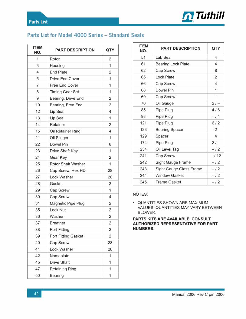
Manual 2006 Rev C p/n 200642
Parts List
Parts List for Model 4000 Series – Standard Seals
ITEM NO. PART DESCRIPTION QTY
1 Rotor 23 Housing 14 End Plate 26 Drive End Cover 17 Free End Cover 18 Timing Gear Set 19 Bearing, Drive End 2
10 Bearing, Free End 212 Lip Seal 413 Lip Seal 114 Retainer 215 Oil Retainer Ring 421 Oil Slinger 122 Dowel Pin 623 Drive Shaft Key 124 Gear Key 225 Rotor Shaft Washer 126 Cap Screw, Hex HD 2827 Lock Washer 2828 Gasket 229 Cap Screw 130 Cap Screw 431 Magnetic Pipe Plug 235 Lock Nut 236 Washer 237 Breather 238 Port Fitting 239 Port Fitting Gasket 240 Cap Screw 2841 Lock Washer 2842 Nameplate 145 Drive Shaft 147 Retaining Ring 150 Bearing 1
ITEM NO. PART DESCRIPTION QTY
51 Lab Seal 461 Bearing Lock Plate 462 Cap Screw 865 Lock Plate 266 Cap Screw 468 Dowel Pin 169 Cap Screw 170 Oil Gauge 2 / –85 Pipe Plug 4 / 698 Pipe Plug – / 4
121 Pipe Plug 6 / 2123 Bearing Spacer 2129 Spacer 4174 Pipe Plug 2 / –234 Oil Level Tag – / 2241 Cap Screw – / 12242 Sight Gauge Frame – / 2243 Sight Gauge Glass Frame – / 2244 Window Gasket – / 2245 Frame Gasket – / 2
NOTES:
• QUANTITIES SHOWN ARE MAXIMUM VALUES. QUANTITIES MAY VARY BETWEEN BLOWER.
PARTS KITS ARE AVAILABLE. CONSULT AUTHORIZED REPRESENTATIVE FOR PART NUMBERS.
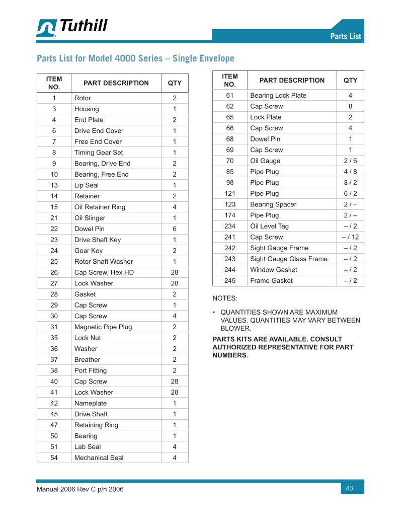
Manual 2006 Rev C p/n 2006 43
Parts List
Parts List for Model 4000 Series – Single Envelope
ITEM NO. PART DESCRIPTION QTY
1 Rotor 23 Housing 14 End Plate 26 Drive End Cover 17 Free End Cover 18 Timing Gear Set 19 Bearing, Drive End 2
10 Bearing, Free End 213 Lip Seal 114 Retainer 215 Oil Retainer Ring 421 Oil Slinger 122 Dowel Pin 623 Drive Shaft Key 124 Gear Key 225 Rotor Shaft Washer 126 Cap Screw, Hex HD 2827 Lock Washer 2828 Gasket 229 Cap Screw 130 Cap Screw 431 Magnetic Pipe Plug 235 Lock Nut 236 Washer 237 Breather 238 Port Fitting 240 Cap Screw 2841 Lock Washer 2842 Nameplate 145 Drive Shaft 147 Retaining Ring 150 Bearing 151 Lab Seal 454 Mechanical Seal 4
ITEM NO. PART DESCRIPTION QTY
61 Bearing Lock Plate 462 Cap Screw 865 Lock Plate 266 Cap Screw 468 Dowel Pin 169 Cap Screw 170 Oil Gauge 2 / 685 Pipe Plug 4 / 898 Pipe Plug 8 / 2
121 Pipe Plug 6 / 2123 Bearing Spacer 2 / –174 Pipe Plug 2 / –234 Oil Level Tag – / 2241 Cap Screw – / 12242 Sight Gauge Frame – / 2243 Sight Gauge Glass Frame – / 2244 Window Gasket – / 2245 Frame Gasket – / 2
NOTES:
• QUANTITIES SHOWN ARE MAXIMUM VALUES. QUANTITIES MAY VARY BETWEEN BLOWER.
PARTS KITS ARE AVAILABLE. CONSULT AUTHORIZED REPRESENTATIVE FOR PART NUMBERS.

Manual 2006 Rev C p/n 200644
Parts List
Parts List for Model 4000 Series – Double Envelope
ITEM NO. PART DESCRIPTION QTY
1 Rotor 23 Housing 14 End Plate 26 Drive End Cover 17 Free End Cover 18 Timing Gear Set 19 Bearing, Drive End 2
10 Bearing, Free End 214 Retainer 215 Oil Retainer Ring 421 Oil Slinger 122 Dowel Pin 623 Drive Shaft Key 124 Gear Key 225 Rotor Shaft Washer 126 Cap Screw, Hex HD 2827 Lock Washer 2828 Gasket 129 Cap Screw 430 Cap Screw 2 / 331 Magnetic Pipe Plug 235 Lock Nut 236 Washer 238 Port Fitting 2840 Cap Screw 28 / 841 Lock Washer 142 Nameplate 145 Drive Shaft 150 Bearing 451 Lab Seal 654 Mechanical Seal 461 Bearing Lock Plate 862 Cap Screw 265 Lock Plate 466 Cap Screw 168 Dowel Pin 169 Cap Screw 170 OIl Gauge 2
ITEM NO. PART DESCRIPTION QTY
74 Spacer 275 O-Ring, Viton 276 Mechanical Seal 177 Drive Shaft Face Seal Sleeve 278 Retaining Ring 282 Washer 183 Lock Nut 185 Pipe Plug 7 / 886 Shim 187 Sleeve 188 O-Ring, Viton 189 Spacer 190 Set Screw 291 Drive Shaft Adapter Seal 192 O-Ring, Viton 193 Cap Screw 498 Pipe Plug 8
108 Magnetic Pipe Plug 1 / –121 Pipe Plug 7 / 3123 Bearing Spacer 2140 O-Ring, Viton 1174 Pipe Plug 2 / –234 Oil Level Tag – / 2241 Cap Screw – / 12242 Sight Gauge Frame – / 2243 Sight Gauge Glass Frame – / 2244 Window Gasket – / 2245 Frame Gasket – / 2
NOTES:
• QUANTITIES SHOWN ARE MAXIMUM VALUES. QUANTITIES MAY VARY BETWEEN BLOWER.
PARTS KITS ARE AVAILABLE. CONSULT AUTHORIZED REPRESENTATIVE FOR PART NUMBERS.
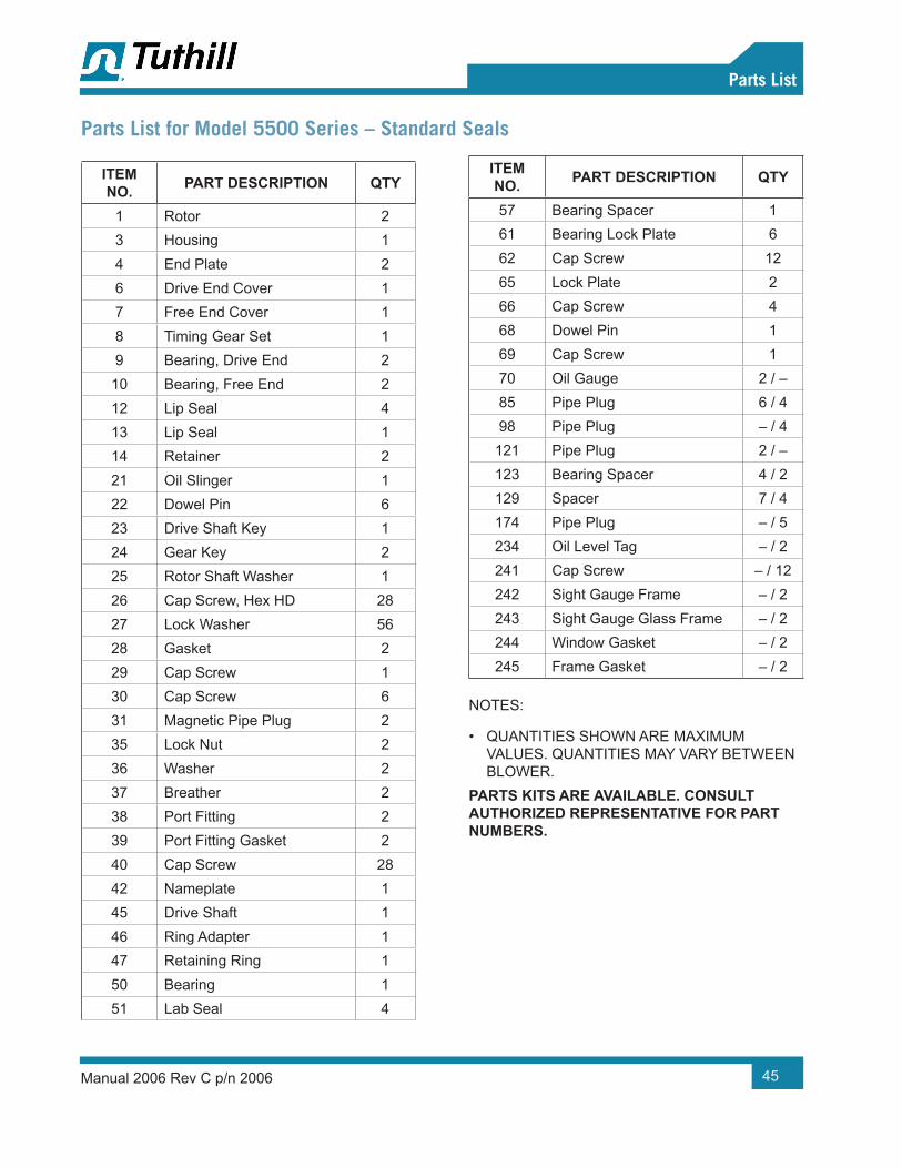
Manual 2006 Rev C p/n 2006 45
Parts List
Parts List for Model 5500 Series – Standard Seals
ITEM NO. PART DESCRIPTION QTY
1 Rotor 23 Housing 14 End Plate 26 Drive End Cover 17 Free End Cover 18 Timing Gear Set 19 Bearing, Drive End 2
10 Bearing, Free End 212 Lip Seal 413 Lip Seal 114 Retainer 221 Oil Slinger 122 Dowel Pin 623 Drive Shaft Key 124 Gear Key 225 Rotor Shaft Washer 126 Cap Screw, Hex HD 2827 Lock Washer 5628 Gasket 229 Cap Screw 130 Cap Screw 631 Magnetic Pipe Plug 235 Lock Nut 236 Washer 237 Breather 238 Port Fitting 239 Port Fitting Gasket 240 Cap Screw 2842 Nameplate 145 Drive Shaft 146 Ring Adapter 147 Retaining Ring 150 Bearing 151 Lab Seal 4
ITEM NO. PART DESCRIPTION QTY
57 Bearing Spacer 161 Bearing Lock Plate 662 Cap Screw 1265 Lock Plate 266 Cap Screw 468 Dowel Pin 169 Cap Screw 170 Oil Gauge 2 / –85 Pipe Plug 6 / 498 Pipe Plug – / 4
121 Pipe Plug 2 / –123 Bearing Spacer 4 / 2129 Spacer 7 / 4174 Pipe Plug – / 5234 Oil Level Tag – / 2241 Cap Screw – / 12242 Sight Gauge Frame – / 2243 Sight Gauge Glass Frame – / 2244 Window Gasket – / 2245 Frame Gasket – / 2
NOTES:
• QUANTITIES SHOWN ARE MAXIMUM VALUES. QUANTITIES MAY VARY BETWEEN BLOWER.
PARTS KITS ARE AVAILABLE. CONSULT AUTHORIZED REPRESENTATIVE FOR PART NUMBERS.

Manual 2006 Rev C p/n 200646
Parts List
Parts List for Model 5500 Series – Single Envelope
ITEM NO. PART DESCRIPTION QTY
1 Rotor 23 Housing 14 End Plate 26 Drive End Cover 17 Free End Cover 18 Timing Gear Set 19 Bearing, Drive End 2
10 Bearing, Free End 213 Lip Seal 114 Retainer 4 / 221 Oil Slinger 122 Dowel Pin 623 Drive Shaft Key 124 Gear Key 225 Rotor Shaft Washer 126 Cap Screw, Hex HD 2827 Lock Washer 5628 Gasket 229 Cap Screw 130 Cap Screw 631 Magnetic Pipe Plug 235 Lock Nut 236 Washer 237 Breather 238 Port Fitting 240 Cap Screw 2842 Nameplate 145 Drive Shaft 146 Adapter Ring 147 Retaining Ring 150 Bearing 151 Lab Seal 454 Mechanical Seal 457 Bearing Spacer 1
ITEM NO. PART DESCRIPTION QTY
61 Bearing Lock Plate 662 Cap Screw 1265 Lock Plate 266 Cap Screw 468 Dowel Pin 169 Cap Screw 170 Oil Gauge 2 / –85 Pipe Plug 10 / 898 Pipe Plug – / 4
123 Bearing Spacer 2 / –174 Pipe Plug 7 / 5234 Oil Level Tag – / 2241 Cap Screw – / 12242 Sight Gauge Frame – / 2243 Sight Gauge Glass Frame – / 2244 Window Gasket – / 2245 Frame Gasket – / 2
NOTES:
• QUANTITIES SHOWN ARE MAXIMUM VALUES. QUANTITIES MAY VARY BETWEEN BLOWER.
PARTS KITS ARE AVAILABLE. CONSULT AUTHORIZED REPRESENTATIVE FOR PART NUMBERS.

Manual 2006 Rev C p/n 2006 47
Parts List
Parts List for Model 5500 Series – Double Envelope
ITEM NO. PART DESCRIPTION QTY
1 Rotor 23 Housing 14 End Plate 26 Drive End Cover 17 Free End Cover 18 Timing Gear Set 19 Bearing, Drive End 2
10 Bearing, Free End 214 Retainer 221 Oil Slinger 122 Dowel Pin 623 Drive Shaft Key 124 Gear Key 225 Rotor Shaft Washer 126 Cap Screw, Hex HD 2829 Cap Screw 430 Cap Screw 2 / 331 Magnetic Pipe Plug 235 Lock Nut 236 Washer 238 Port Fitting 2840 Cap Screw 28 / 842 Nameplate 145 Drive Shaft 150 Bearing 451 Lab Seal 654 Mechanical Seal 457 Bearing Spacer 161 Bearing Lock Plate 662 Cap Screw 265 Lock Plate 466 Cap Screw 168 Dowel Pin 169 Cap Screw 1
ITEM NO. PART DESCRIPTION QTY
70 Oil Gauge 274 Spacer 275 O-Ring, Viton 277 Drive Shaft Face Seal Sleeve 280 Washer 1 / –82 Washer 183 Lock Nut 185 Pipe Plug 7 / 886 Shim 186 Shim 491 Drive Shaft Adapter Seal 192 O-Ring, Viton 193 Cap Screw 498 Pipe Plug 8
123 Bearing Spacer 2136 Lock Washer 1 / –140 O-Ring, Viton 1174 Pipe Plug 2 / –224 Oil Retainer Plate 4 / 1225 Cap Screw 4234 Oil Level Tag – / 2241 Cap Screw – / 12242 Sight Gauge Frame – / 2243 Sight Gauge Glass Frame – / 2244 Window Gasket – / 2245 Frame Gasket – / 2255 Roll Pin 2 / –
NOTES:
• QUANTITIES SHOWN ARE MAXIMUM VALUES. QUANTITIES MAY VARY BETWEEN BLOWER.
PARTS KITS ARE AVAILABLE. CONSULT AUTHORIZED REPRESENTATIVE FOR PART NUMBERS.

Manual 2006 Rev C p/n 200648
Assembly Drawings
ASSEMBLY DRAWINGSModel 3200 – Standard Seals – Cutaway View

Manual 2006 Rev C p/n 2006 49
Assembly Drawings
Model 3200 – Standard Seals – Side and End Views
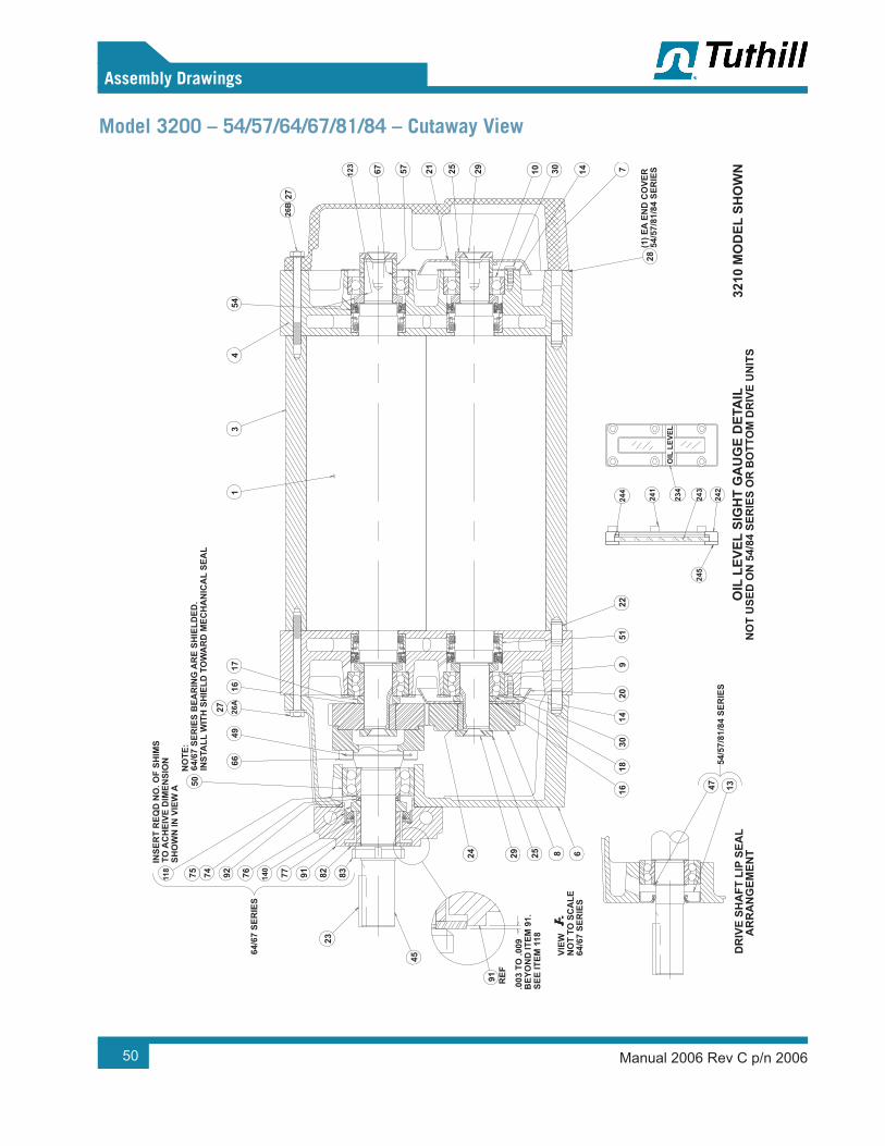
Manual 2006 Rev C p/n 200650
Assembly Drawings
Model 3200 – 54/57/64/67/81/84 – Cutaway View
DR
IVE
SHA
FT L
IP S
EAL
A
RR
AN
GEM
ENT
NO
T U
SED
ON
54/
84 S
ERIE
S O
R B
OTT
OM
DR
IVE
UN
ITS
OIL
LEV
EL S
IGH
T G
AU
GE
DET
AIL
3210
MO
DEL
SH
OW
N
140
118
26A
234
242
243
241
244
245
123
26B
54/5
7/81
/84
SER
IES
16 47 13
.003
TO
.009
BEY
ON
D IT
EM 9
1.SE
E IT
EM 1
18
64/6
7 SE
RIE
SN
OT
TO S
CA
LEVI
EW
91 REF
625 82924
1830
2014
951
22
INSE
RT
REQ
D N
O. O
F SH
IMS
TO A
CH
EIVE
DIM
ENSI
ON
SHO
WN
IN V
IEW
A
45
238391 82
64/6
7 SE
RIE
S
92 777675 74
NO
TE:
64/6
7 SE
RIE
S B
EAR
ING
AR
E SH
IELD
ED.
INST
ALL
WIT
H S
HIE
LD T
OW
AR
D M
ECH
AN
ICA
L SE
AL
6649
16
50
2717
25
(1) E
A EN
D C
OVE
R54
/57/
81/8
4 SE
RIE
S28
71410 3029
13
4
67 2157
54
27

Manual 2006 Rev C p/n 2006 51
Assembly Drawings
Model 4000 – Standard Seal – Cutaway Views
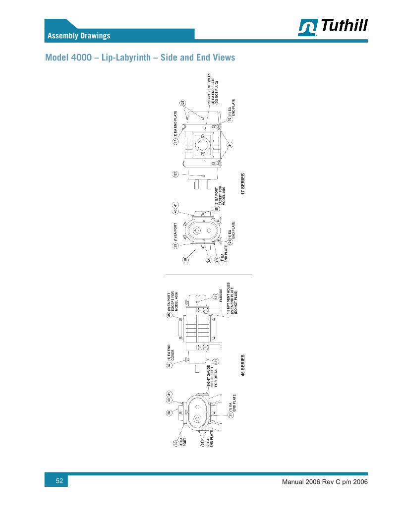
Manual 2006 Rev C p/n 200652
Assembly Drawings
Model 4000 – Lip-Labyrinth – Side and End Views
58
Assembly Drawings
Manual 2006 Rev B p/n 2006
Model 4000 – Lip-Labyrinth – Side and End Views
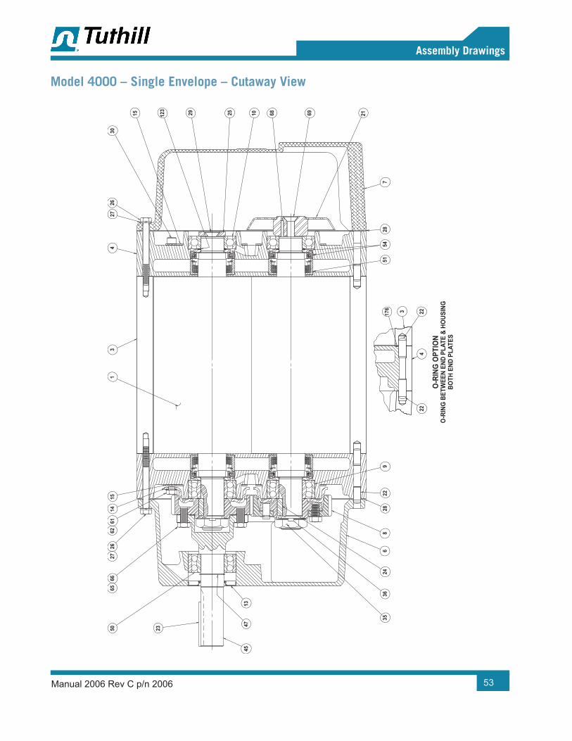
Manual 2006 Rev C p/n 2006 53
Assembly Drawings
Model 4000 – Single Envelope – Cutaway View
59
Assembly Drawings
Manual 2006 Rev B p/n 2006
Model 4000 – Single Envelope – Cutaway View
O-R
ING
BET
WEE
N EN
D PL
ATE
& HO
USIN
GBO
TH E
ND P
LATE
S
O-R
ING
OPT
ION
3536
246
828
229
22
62
4547
13
235066
6526
2714
6115
1
5451
28
42217
6 3
7
2169
34
25 10 6829
2726
123
15
30

Manual 2006 Rev C p/n 200654
Assembly Drawings
Model 4000 – Single Envelope – Side and End Views
60
Assembly Drawings
Manual 2006 Rev B p/n 2006
Model 4000 – Single Envelope – Side and End Views
4000
(400
9 SH
OW
N)
TOP
DRIV
EBO
TTO
M D
RIVE
4000
(400
9 SH
OW
N)
RIG
HT D
RIVE
LEFT
DRI
VE
OPT
IONA
L FL
ANG
ED P
ORT
FIT
TING
DET
AIL
OIL
LEV
EL S
IGHT
GAU
GE
DETA
IL
121
174
121
234
245
244
242
241
243
121
121
121
174
174
(1) E
A EN
D PL
ATE
(1) E
A EN
D PL
ATE
(1) E
A EN
D PL
ATE
38
(2) E
A PO
RT85
31
4140
37
(2) E
A EN
D PL
ATE
98
OIL
LEV
EL S
IGHT
GAU
GE
(1) E
A EN
D PL
ATE
(SEE
DET
AIL)
(1) E
A EN
D PL
ATE
313840
4137
(2) E
A PO
RT85
70(1
) EA
END
PLAT
E
(4) E
A EN
D PL
ATE
98
4009
(1) E
A PO
RT85
(1) E
A PO
RT
4012(2) E
A PO
RT85
(1) E
A PO
RT
FARS
IDE
98(2
) EA
END
PLAT
E
37

Manual 2006 Rev C p/n 2006 55
Assembly Drawings
Model 4000 – Single Envelope (Cooling Coil Option) – Side and End Views
61
Assembly Drawings
Manual 2006 Rev B p/n 2006
Model 4000 – Single Envelope (Cooling Coil Option) – Side and End Views
HORI
ZONT
AL F
LOW
VERT
ICAL
FLO
W
COO
LING
CO
IL O
PTIO
N
180
166
180
166
181
180
166
181
180
181
166
181
9797
97
98
97
98
FARS
IDE
97
9798
96
COO
LING
CO
IL D
ETAI
L(T
YP B
OTH
END
S)SC
ALE:
NO
NE
SEC
95
98
SEE
SEC
9797
94
97

Manual 2006 Rev C p/n 200656
Assembly Drawings
Model 4000 – Double Envelope – Cutaway View
62
Assembly Drawings
Manual 2006 Rev B p/n 2006
Model 4000 – Double Envelope – Cutaway View
O-R
ING
OPT
ION
O-R
ING
BET
WEE
N EN
D PL
ATE
& HO
USIN
GBO
TH E
ND P
LATE
S
3536
24
.000
TO
.005
BELO
W IT
EM 9
1
INSE
RT S
HIM
S (IF
REQ
D) B
ETW
EEN
SLEE
VE (I
TEM
87)
& B
EARI
NG(IT
EM 5
0) T
OAC
HIEV
EDI
MEN
SIO
N SH
OW
N AB
OVE
9282
86
69
228
22
88 7514023
91
45878389
9076
7793
7450
6665
6162
1415
51
42217
6 3
547
2169
41
3
25 681029
1526
30
123

Manual 2006 Rev C p/n 2006 57
Assembly Drawings
Model 4000 – 64-67-68 – Side and End Views
63
Assembly Drawings
Manual 2006 Rev B p/n 2006
Model 4000 – 64-67-68 – Side and End Views
174
121
121
121
174
174
234
242
241
243
121
245
244
98
(1) E
A EN
D PL
ATE
TOP
DRIV
EBO
TTO
M D
RIVE
(1) E
A EN
D PL
ATE
4085
4000
-64
4009
SHO
WN
(1) E
A EN
D PL
ATE
31
(2) E
A PO
RT38
85
(4) E
A EN
D PL
ATE
98
LEFT
DRI
VERI
GHT
DRI
VE
(2) E
A EN
D PL
ATE
9885
OIL
LEV
EL S
IGHT
GAU
GE
(1) E
A EN
D PL
ATE
(SEE
DET
AIL)
(1) E
A EN
D PL
ATE
31
4009
SHO
WN
4000
-67
3885
40
OPT
IONA
L FL
ANG
ED P
ORT
FIT
TING
DET
AIL
(1) E
A EN
D PL
ATE
70
121
(1) E
A EN
D PL
ATE
4009
(1) E
A PO
RT85
(1) E
A PO
RT
4012
(2) E
A PO
RT85
(1) E
A PO
RT
OIL
LEV
EL S
IGHT
GAU
GE
DETA
IL
(2) E
A EN
D PL
ATE
(2) E
A PO
RT
121
FARS
IDE

Manual 2006 Rev C p/n 200658
Assembly Drawings
Model 4000 – 64-67-68 (Cooling Coil Option) – Side and End Views
VERT
ICAL
FLO
W
TOP
DRIV
EBO
TTO
M D
RIVE
LEFT
DRI
VERI
GHT
DRI
VE
COO
LING
CO
IL O
PTIO
NCOO
LING
CO
IL D
ETAI
L
180
166
181
166
180
273
152
274
181
180
166
166
271
272
274
273
152
166
181
9718
0
1801
6618
1
HORI
ZONT
AL F
LOW
97
97
97
97
96
9798
FARS
IDE
(TYP
BO
TH E
NDS)
SCAL
E: N
ONE
SEC
95
9897SE
E SE
C
97
94
97
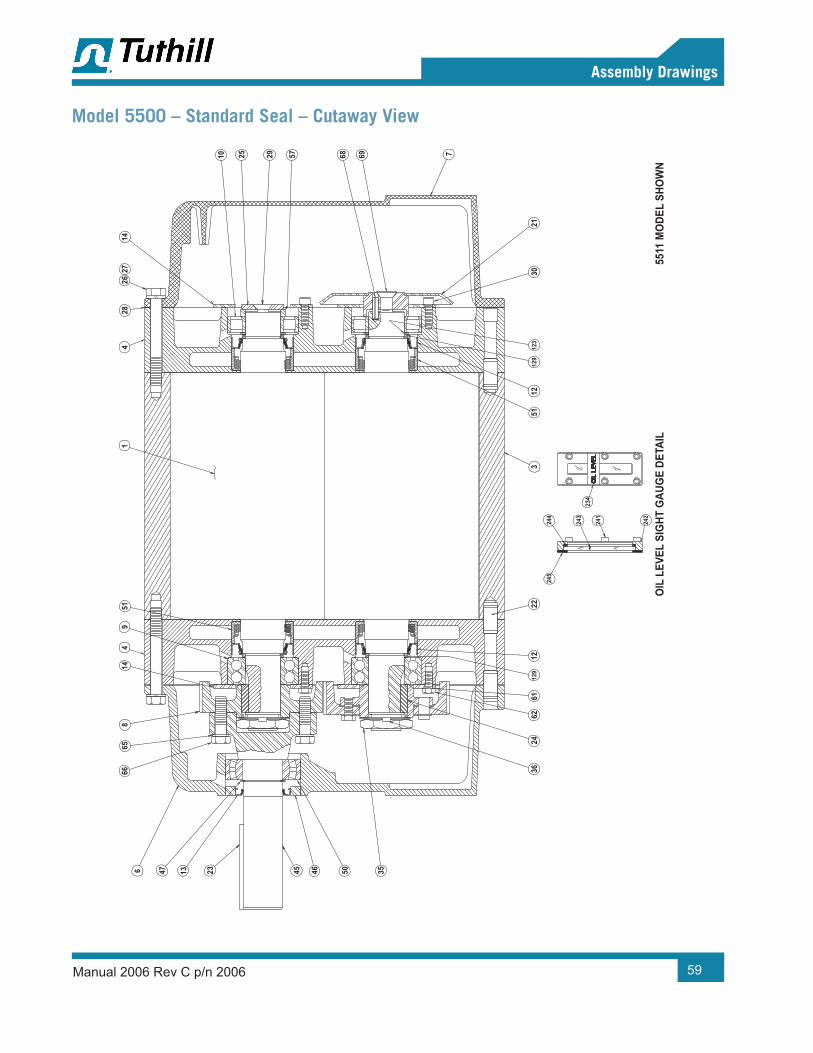
Manual 2006 Rev C p/n 2006 59
Assembly Drawings
Model 5500 – Standard Seal – Cutaway View
OIL
LEV
EL S
IGHT
GAU
GE
DETA
IL55
11 M
ODE
L SH
OW
N24
2
245
243
241
234
244
123
129
129
35
6136
2462
~
1222
3
50464513 2347666
658
144
951
5112
3021
7
14
2628
2714
10 6968572925

Manual 2006 Rev C p/n 200660
Assembly Drawings
Model 5500 – Single Envelope – Cutaway View
TYP
FOR
BOTH
END
PLA
TES
SCAL
E: 1
/2
O-R
ING
SEA
LING
ARR
ANG
EMEN
T O
PTIO
N (R
)55
14 S
HOW
N
126
123
176
22
36 35 8
662
61
4
2222
2424
4547
4623
13
5014
6665
49
31
28
217
3069
5154
685729 2510
1427
26

Manual 2006 Rev C p/n 2006 61
Assembly Drawings
Model 5500 – Single Envelope – Side and End Views
RIG
HT D
RIVE
LEFT
DRI
VE55
0055
11 S
HOW
N
5500
(TO
P DR
IVE)
5511
SHO
WN
FLAN
GED
PO
RT F
ITTI
NG D
ETAI
LM
ODE
LS 5
514
& 55
18
NPT
PORT
FIT
TING
DET
AIL
MO
DEL
5507
OIL
LEV
EL S
IGHT
GAU
GE
DETA
IL
5500
(BO
TTO
M D
RIVE
)55
11 S
HOW
N
174
174
174
174
174
174
3817
4
174
241
242
245
243
244
234
174
174
174
(2) E
A EN
D PL
ATE
(2) E
AEN
D PL
ATE
98
(1) E
A EN
D PL
ATE
3185
(SEE
PO
RT D
ETAI
L)38
37
2740
(1) E
AEN
D PL
ATE
85
(1) E
AEN
D PL
ATE
(1) E
AEN
D PL
ATE
31
(SEE
PO
RTDE
TAIL
)27
4038
(1) E
AEN
D PL
ATE
(2) E
AEN
D PL
ATE
85
OIL
LEV
EL S
IGHT
GAU
GE
(1) E
A EN
D CO
VER
(SEE
DET
AIL)
(1) E
A EN
D PL
ATE
(2) E
A PO
RT85
37
OIL
LEV
EL S
IGHT
GAU
GE
(1) E
A EN
D PL
ATE
(SEE
DET
AIL)
85
37
FARS
IDE
(2) E
A PO
RT85
3885
85
85(1
) EA
END
PLAT
E
(1) E
AEN
D PL
ATE
(1) E
AEN
D PL
ATE
31
98(S
EE P
ORT
DET
AIL)
4038
(1) E
AEN
D PL
ATE
70(2
) EA
END
PLAT
E85
174
(1) E
A EN
D PL
ATE
(2) E
A PO
RT37

Manual 2006 Rev C p/n 200662
Assembly Drawings
Model 5500 – Single Envelope (Cooling Coil Option) – Side And End Views
VENT
ING
DET
AIL
VERT
ICAL
FLO
W
HORI
ZONT
AL F
LOW
NPT
5507
NPT
5507
NPT
5511
FLAN
GED
5507
, 551
1, 5
514,
& 5
518
NPT
5511
FLAN
GED
5507
, 551
1, 5
514,
& 5
518
HORI
ZONT
AL F
LOW
BOTT
OM
DRI
VETO
P DR
IVE
VERT
ICAL
FLO
WRI
GHT
DRI
VELE
FT D
RIVE
COO
LING
CO
IL D
ETAI
LSC
ALE:
1/2
VENT
TO
INLE
T PO
RT R
IGHT
SID
E &
TOP
INLE
T SH
OW
N(S
EE F
ACTO
RY F
OR
FLO
W D
IREC
TIO
N)
180
166
181
181
1661
80
120
163
120
159
163
159
120
180
163
159
120
163
159
180
163
159
259
2581
3214
9
163
159
132
259
149
258
181
166
180
166
180
1801
6618
1
9797
98
THIS
SID
E
97
97FA
RSID
E97
SEC
98SE
E SE
C 97
98
97
94
9597 96

Manual 2006 Rev C p/n 2006 63
Assembly Drawings
Model 5500 – Double Envelope – Cutaway View
O-R
ING
SEA
LING
ARR
ANG
EMEN
T O
PTIO
N (R
)TY
P FO
R BO
TH E
ND P
LATE
SSC
ALE:
1/2
5514
MO
DEL
SHO
WN
DRIV
E SH
AFT
MEC
HANI
CAL
SEAL
ASS
EMBL
Y DE
TAIL
SCAL
E:FU
LL
140
255
224
225 13
6
123
126
176
51
INSE
RT S
HIM
S (IF
REQ
D)BE
TWEE
N SP
ACER
(ITE
M 7
4)AN
D DR
IVE
SHAF
T BE
ARIN
GTO
ACH
IEVE
DIM
ENSI
ON
SHO
WN
82.0
00 T
O .0
05BE
LOW
ITEM
91
92
50
74
8675
83
45
9177
9354
35362040
2462
6122
45
64/6
4W S
ERIE
STO
P DR
IVE
ONL
Y
80
23
9193
6
6665
814
49
422
2130
6968
13
54
572910 25
2614
7

Manual 2006 Rev C p/n 200664
Assembly Drawings
Model 5500 – Double Envelope – Side and End Views
RIG
HT D
RIVE
LEFT
DRI
VE55
0055
11 S
HOW
N
5511
SHO
WN
5500
(TO
P DR
IVE)
FLAN
GED
PO
RT F
ITTI
NG D
ETAI
L
NPT
PORT
FIT
TING
DET
AIL
MO
DELS
551
4 &
5518
MO
DEL
5507
OIL
LEV
EL S
IGHT
GAU
GE
DETA
IL
5500
(BO
TTO
M D
RIVE
)55
11 S
HOW
N
174
174
174
174
174
174
174
174
234
241
242
245
243
244
174
174
174
174 17
4(2
) EA
END
PLAT
E
(2) E
AEN
D PL
ATE
98
85
(1) E
A EN
D PL
ATE
3185
(SEE
PO
RT D
ETAI
L)38
40
85(1
) EA
END
PLAT
E
(1) E
AEN
D PL
ATE
31(1
) EA
END
PLAT
E
85(S
EE P
ORT
DET
AIL)
4038
85(1
) EA
END
PLAT
E(2
) EA
END
PLAT
E
OIL
LEV
EL S
IGHT
GAU
GE
(1) E
A EN
D CO
VER
(SEE
DET
AIL)
(1) E
A EN
D PL
ATE
85(2
) EA
PORT
38
OIL
LEV
EL S
IGHT
GAU
GE
(1) E
A EN
D PL
ATE
(SEE
DET
AIL)
85
FARS
IDE
85(2
) EA
PORT
8538
85
85(1
) EA
END
PLAT
E
(1) E
AEN
D PL
ATE
31(1
) EA
END
PLAT
E
85(S
EE P
ORT
DET
AIL)
3840
8570
(1) E
AEN
D PL
ATE
(2) E
AEN
D PL
ATE17
4
(1) E
A EN
D PL
ATE
(2) E
A PO
RT

Manual 2006 Rev C p/n 2006 65
Assembly Drawings
Model 5500 – Double Envelope (Cooling Coil Option) – Side and End Views
VENT
ING
DET
AIL
HORI
ZONT
AL F
LOW
BOTT
OM
DRI
VETO
P DR
IVE
VERT
ICAL
FLO
W
HORI
ZONT
AL F
LOW
NPT
5507
NPT
5507
NPT
5511
FLAN
GED
5507
, 551
1, 5
514,
& 5
518
NPT
5511
FLAN
GED
5507
, 551
1, 5
514,
& 5
518
VERT
ICAL
FLO
W
RIG
HT D
RIVE
LEFT
DRI
VE
COO
LING
CO
IL D
ETAI
LSC
ALE:
1/2
VENT
TO
INLE
T PO
RT R
IGHT
SID
E &
TOP
INLE
T SH
OW
N(S
EE F
ACTO
RY F
OR
FLO
W D
IREC
TIO
N)
180
166
180
181
166
273
152
274
181
166
180
120
163
120
159
163
159
120
180
163
159
120
163
159
180
163
159
259
258
132
149
163
159
132
259
149
258
181
274
273
152
166
180
166
272
271
274
166
180
180
166
181
94
9597 96
9797
98TH
IS S
IDE
97
97
FARS
IDE
97SEC
97
SEE
SEC
97
98
97

Manual 2006 Rev C p/n 200666
Assembly Drawings

This page intentionally blank

This page intentionally blank

WARRANTY – BLOWER PRODUCTSSubject to the terms and conditions hereinafter set forth and set forth in General Terms of Sale, Tuthill Springfield (the Seller) warrants products and parts of its manufacture, when shipped, and its work (including installation and start-up) when performed, will be of good quality and will be free from defects in material and workmanship. This warranty applies only to Seller’s equipment, under use and service in accordance with seller’s written instructions, recommendations and ratings for installation, operating, maintenance and service of products, for a period as stated in the table below. Because of varying conditions of installation and operation, all guarantees of performance are subject to plus or minus 5% variation. (Non-standard materials are subject to a plus or minus 10% variation)
PRODUCTTYPE
TYPE OF APPLICATION
ATMOSPHERIC AIR OR PROCESS AIR WITHOUT LIQUIDS PRESENT
PROCESS GASES OTHER THAN AIR, OR ANY LIQUID INJECTED APPLICATION
New(Qx™ models only)
30 months from date of shipment, or 24 months after initial startup date, whichever occurs first. Consult Factory
New(all other models)
24 months from date of shipment, or 18 months after initial startup date, whichever occurs first
18 months from date of shipment, or 12 months after initial startup date, whichever occurs first
Repair 12 months from date of shipment, or remaining warranty period, whichever is greater
12 months from date of shipment, or remaining warranty period, whichever is greater
THIS WARRANTY EXTENDS ONLY TO BUYER AND/OR ORIGINAL END USER, AND IN NO EVENT SHALL THE SELLER BE LIABLE FOR PROPERTY DAMAGE SUSTAINED BY A PERSON DESIGNATED BY THE LAW OF ANY JURISDICTION AS A THIRD PARTY BENEFICIARY OF THIS WARRANTY OR ANY OTHER WARRANTY HELD TO SURVIVE SELLER’S DISCLAIMER.
All accessories furnished by Seller but manufactured by others bear only that manufacturer’s standard warranty.
All claims for defective products, parts, or work under this warranty must be made in writing immediately upon discovery and, in any event within one (1) year from date of shipment of the applicable item and all claims for defective work must be made in writing immediately upon discovery and in any event within one (1) year from date of completion thereof by Seller. Unless done with prior written consent of Seller, any repairs, alterations or disassembly of Seller’s equipment shall void warranty. Installation and transportation costs are not included and defective items must be held for Seller’s inspection and returned to Seller’s Ex-works point upon request.
THERE ARE NO WARRANTIES, EXPRESSED, IMPLIED OR STATUTORY WHICH EXTEND BEYOND THE DESCRIPTION ON THE FACE HEREOF, INCLUDING WITHOUT LIMITATION, THE IMPLIED WARRANTIES OF MERCHANTABILITY AND FITNESS OF PURPOSE.
After Buyer’s submission of a claim as provided above and its approval, Seller shall at its option either repair or replace its product, part, or work at the original Ex-works point of shipment, or refund an equitable portion of the purchase price.
The products and parts sold hereunder are not warranted for operation with erosive or corrosive material or those which may lead to build up of material within the product supplied, nor those which are incompatible with the materials of construction. The Buyer shall have no claim whatsoever and no product or part shall be deemed to be defective by reason of failure to resist erosive or corrosive action nor for problems resulting from build-up of material within the unit nor for problems due to incompatibility with the materials of construction.
Any improper use, operation beyond capacity, substitution of parts not approved by Seller, or any alteration or repair by others in such manner as in Seller’s judgment affects the product materially and adversely shall void this warranty.
No employee or representative of Seller other than an Officer of the Company is authorized to change this warranty in any way or grant any other warranty. Any such change by an Officer of the Company must be in writing.
The foregoing is Seller’s only obligation and Buyer’s only remedy for breach of warranty, and except for gross negligence, willful misconduct and remedies permitted under the General Terms of Sale in the sections on CONTRACT PERFORMANCE, INSPECTION AND ACCEPTANCE and the PATENTS Clause hereof, the foregoing is BUYER’S ONLY REMEDY HEREUNDER BY WAY OF BREACH OF CONTRACT, TORT OR OTHERWISE, WITHOUT REGARD TO WHETHER ANY DEFECT WAS DISCOVERED OR LATENT AT THE TIME OF DELIVERY OF THE PRODUCT OR WORK. In no event shall Buyer be entitled to incidental or consequential damages. Any action for breach of this agreement must commence within one (1) year after the cause of action has occurred.
May 2008

IMPORTANTAll blowers manufactured by Tuthill Springfield are date coded at time of shipment. In order to assure you of the full benefits of the product warranty, please complete, tear out and return the product registration card, or register online at tuthillvacuumblower.com.
OPERATING DATA FORM / PRODUCT REGISTRATIONIt is to the user’s advantage to have the requested data filled in below and available in the event a problem should develop in the blower or the system. This information is also helpful when ordering spare parts.
Model No. V-Belt Size Length
Serial No. Type of Lubrication
Startup Date
Pump RPM Operating Vacuum
Pump SheaveDiameter Any other Special Accessories Supplied or in use:
Motor SheaveDiameter
Motor RPM HP
NOTES:

Manual 2006 Rev C p/n 200602/20
Tuthill Springfield4840 West Kearney StreetSpringfield, Missouri USA 65803-8702O 417.865.8715 800.825.6937 F 417.865.2950tuthillvacuumblower.com
For Service & Repair, TechnicalSupport, or Product Sales contact:
Copyright © 2020 Tuthill Springfield All rights reserved. Product information and specifications subject to change.
INTERNATIONAL QUALITY STANDARD
REGISTERED
VACUUM & BLOWER SYSTEMS
TUTHILL CORPORATION