rotary sieve hopper - nordsonemanuals.nordson.com/finishing/files/stockport/317213d.pdf · ii 3d t...
TRANSCRIPT

Rotary Sieve Hopper
Customer Product ManualPart 317213D
Issued 12/11
NORDSON CORPORATION AMHERST, OHIO USA
For parts and technical support, call theFinishing Customer Support Center at (800) 433-9319.
Check http://emanuals.nordson.com/finishing for the latest version.This document is subject to change without notice.

Part 317213D E 2011 Nordson CorporationManual 12/11
Contact UsNordson Corporation welcomes requests for information, comments, andinquiries about its products. General information about Nordson can befound on the Internet using the following address:http://www.nordson.com.Address all correspondence to:
Nordson CorporationAttn: Customer Service555 Jackson StreetAmherst, OH 44001
NoticeThis is a Nordson Corporation publication which is protected by copyright.Original copyright date 2011. No part of this document may bephotocopied, reproduced, or translated to another language without theprior written consent of Nordson Corporation. The information containedin this publication is subject to change without notice.
Trademarks
Nordson and the Nordson logo are registered trademarks of Nordson Corporation.

DECLARATION of CONFORMITY
PRODUCT: Rotary Sieve
This is a Rotary Sieve used for separating powder particles and removing the fines whichdo not charge well and become scrap.
APPLICABLE DIRECTIVES:
2006/42/EC -- Machinery Directive94/9/EC -- ATEX Directive
STANDARDS USED TO VERIFY COMPLIANCE:
EN1127 EN13463--1 EN13463--5
II 3D T 200C
Date: 12th December 2011Mike HansingerManager Engineering DevelopmentIndustrial Coating Systems
Nordson Authorised Representative in the EUContact: Operations ManagerIndustrial Coating SystemsNordson Deutschland GmbHHeinrich--Hertz--Strasse 42--44D--40699 Erkrath
Nordson Corporation -- Westlake, Ohio

Table of Contents I
P/N 317213DE 2011 Nordson Corporation
Table of Contents
Nordson International O-1. . . . . . . . . . . . . . . . . . . . . . . . . . . . . . . . . . .http://www.nordson.com/Directory O-1. . . . . . . . . . . . . . . . . . . . . . . . . .Europe O-1. . . . . . . . . . . . . . . . . . . . . . . . . . . . . . . . . . . . . . . . . . . . . . . . .Distributors in Eastern & Southern Europe O-1. . . . . . . . . . . . . . . .
Outside Europe / Hors d’Europe / Fuera de Europa O-2. . . . . . . . . . .Africa / Middle East O-2. . . . . . . . . . . . . . . . . . . . . . . . . . . . . . . . . . . .Asia / Australia / Latin America O-2. . . . . . . . . . . . . . . . . . . . . . . . . .Japan O-2. . . . . . . . . . . . . . . . . . . . . . . . . . . . . . . . . . . . . . . . . . . . . . . .North America O-2. . . . . . . . . . . . . . . . . . . . . . . . . . . . . . . . . . . . . . . .
Safety 1-1. . . . . . . . . . . . . . . . . . . . . . . . . . . . . . . . . . . . . . . . . . . . . . . . . .Introduction 1-1. . . . . . . . . . . . . . . . . . . . . . . . . . . . . . . . . . . . . . . . . . . . .Qualified Personnel 1-1. . . . . . . . . . . . . . . . . . . . . . . . . . . . . . . . . . . . . .Intended Use 1-1. . . . . . . . . . . . . . . . . . . . . . . . . . . . . . . . . . . . . . . . . . . .Regulations and Approvals 1-2. . . . . . . . . . . . . . . . . . . . . . . . . . . . . . . .Personal Safety 1-2. . . . . . . . . . . . . . . . . . . . . . . . . . . . . . . . . . . . . . . . .Fire Safety 1-2. . . . . . . . . . . . . . . . . . . . . . . . . . . . . . . . . . . . . . . . . . . . . .Grounding 1-3. . . . . . . . . . . . . . . . . . . . . . . . . . . . . . . . . . . . . . . . . . . . . .Action in the Event of a Malfunction 1-4. . . . . . . . . . . . . . . . . . . . . . . .Disposal 1-4. . . . . . . . . . . . . . . . . . . . . . . . . . . . . . . . . . . . . . . . . . . . . . . .
Description 2-1. . . . . . . . . . . . . . . . . . . . . . . . . . . . . . . . . . . . . . . . . . . . .Intended Use 2-1. . . . . . . . . . . . . . . . . . . . . . . . . . . . . . . . . . . . . . . . . . . .Unintended use 2-1. . . . . . . . . . . . . . . . . . . . . . . . . . . . . . . . . . . . . . . . . .Residual Risks 2-1. . . . . . . . . . . . . . . . . . . . . . . . . . . . . . . . . . . . . . . . . .Features 2-2. . . . . . . . . . . . . . . . . . . . . . . . . . . . . . . . . . . . . . . . . . . . . . . .
Installation 3-1. . . . . . . . . . . . . . . . . . . . . . . . . . . . . . . . . . . . . . . . . . . . .Transport 3-1. . . . . . . . . . . . . . . . . . . . . . . . . . . . . . . . . . . . . . . . . . . . . . .Unpacking 3-1. . . . . . . . . . . . . . . . . . . . . . . . . . . . . . . . . . . . . . . . . . . . . .Removing 3-1. . . . . . . . . . . . . . . . . . . . . . . . . . . . . . . . . . . . . . . . . . . . . . .Storage 3-1. . . . . . . . . . . . . . . . . . . . . . . . . . . . . . . . . . . . . . . . . . . . . . . . .Disposal 3-1. . . . . . . . . . . . . . . . . . . . . . . . . . . . . . . . . . . . . . . . . . . . . . . .Setting Up the Unit 3-2. . . . . . . . . . . . . . . . . . . . . . . . . . . . . . . . . . . . . . .Electrical 3-2. . . . . . . . . . . . . . . . . . . . . . . . . . . . . . . . . . . . . . . . . . . . . . .Pneumatic 3-2. . . . . . . . . . . . . . . . . . . . . . . . . . . . . . . . . . . . . . . . . . . . . .
Operation 4-1. . . . . . . . . . . . . . . . . . . . . . . . . . . . . . . . . . . . . . . . . . . . . .Initial Startup 4-1. . . . . . . . . . . . . . . . . . . . . . . . . . . . . . . . . . . . . . . . . . . .Daily Operation 4-1. . . . . . . . . . . . . . . . . . . . . . . . . . . . . . . . . . . . . . . . . .
Table of ContentsII
P/N 317213D E 2011 Nordson Corporation
Maintenance 5-1. . . . . . . . . . . . . . . . . . . . . . . . . . . . . . . . . . . . . . . . . . .Daily Maintenance 5-1. . . . . . . . . . . . . . . . . . . . . . . . . . . . . . . . . . . . . . .Yearly Maintenance 5-1. . . . . . . . . . . . . . . . . . . . . . . . . . . . . . . . . . . . . .Screen Replacement 5-1. . . . . . . . . . . . . . . . . . . . . . . . . . . . . . . . . . . . .Removal of Sieve Basket 5-2. . . . . . . . . . . . . . . . . . . . . . . . . . . . . . .Removing Existing Sieve Screens 5-2. . . . . . . . . . . . . . . . . . . . . . .Fitting New Sieve Screens 5-2. . . . . . . . . . . . . . . . . . . . . . . . . . . . . .Replacing Fluid Bed 5-3. . . . . . . . . . . . . . . . . . . . . . . . . . . . . . . . . . .
Troubleshooting 6-1. . . . . . . . . . . . . . . . . . . . . . . . . . . . . . . . . . . . . . . .Trouble Shooting Guide 6-1. . . . . . . . . . . . . . . . . . . . . . . . . . . . . . . . . . .
Parts 7-1. . . . . . . . . . . . . . . . . . . . . . . . . . . . . . . . . . . . . . . . . . . . . . . . . . .Introduction 7-1. . . . . . . . . . . . . . . . . . . . . . . . . . . . . . . . . . . . . . . . . . . . .Using the Illustrated Parts List 7-1. . . . . . . . . . . . . . . . . . . . . . . . . .
Parts List 7-2. . . . . . . . . . . . . . . . . . . . . . . . . . . . . . . . . . . . . . . . . . . . . . .Front Elevation 7-2. . . . . . . . . . . . . . . . . . . . . . . . . . . . . . . . . . . . . . . .Cross Sectional View -- Metric 7-4. . . . . . . . . . . . . . . . . . . . . . . . . . .Cross Sectional View -- Imperial 7-6. . . . . . . . . . . . . . . . . . . . . . . . .
Specifications 8-1. . . . . . . . . . . . . . . . . . . . . . . . . . . . . . . . . . . . . . . . . .Electrical 8-1. . . . . . . . . . . . . . . . . . . . . . . . . . . . . . . . . . . . . . . . . . . . . . .Noise 8-1. . . . . . . . . . . . . . . . . . . . . . . . . . . . . . . . . . . . . . . . . . . . . . . . . .Pneumatic 8-1. . . . . . . . . . . . . . . . . . . . . . . . . . . . . . . . . . . . . . . . . . . . . .Dimensions and Weight 8-2. . . . . . . . . . . . . . . . . . . . . . . . . . . . . . . . . . .Double Pump Mount 8-2. . . . . . . . . . . . . . . . . . . . . . . . . . . . . . . . . . .Circuit Schematic 8-3. . . . . . . . . . . . . . . . . . . . . . . . . . . . . . . . . . . . . .
Accessories 9-1. . . . . . . . . . . . . . . . . . . . . . . . . . . . . . . . . . . . . . . . . . . .Magnetic Seperator 9-2. . . . . . . . . . . . . . . . . . . . . . . . . . . . . . . . . . . . . .Castor Kit 9-3. . . . . . . . . . . . . . . . . . . . . . . . . . . . . . . . . . . . . . . . . . . . . . .Vent Adapter 9-4. . . . . . . . . . . . . . . . . . . . . . . . . . . . . . . . . . . . . . . . . . . .

O-1Introduction
E 2011 Nordson CorporationAll rights reserved NI_EN_O-0211
Nordson Internationalhttp://www.nordson.com/Directory
Country Phone Fax
EuropeAustria 43-1-707 5521 43-1-707 5517
Belgium 31-13-511 8700 31-13-511 3995
Czech Republic 4205-4159 2411 4205-4124 4971
Denmark Hot Melt 45-43-66 0123 45-43-64 1101
Finishing 45-43-200 300 45-43-430 359
Finland 358-9-530 8080 358-9-530 80850
France 33-1-6412 1400 33-1-6412 1401
Germany Erkrath 49-211-92050 49-211-254 658
Lüneburg 49-4131-8940 49-4131-894 149
Nordson UV 49-211-9205528 49-211-9252148
EFD 49-6238 920972 49-6238 920973
Italy 39-02-216684-400 39-02-26926699
Netherlands 31-13-511 8700 31-13-511 3995
Norway Hot Melt 47-23 03 6160 47-23 68 3636
Poland 48-22-836 4495 48-22-836 7042
Portugal 351-22-961 9400 351-22-961 9409
Russia 7-812-718 62 63 7-812-718 62 63
Slovak Republic 4205-4159 2411 4205-4124 4971
Spain 34-96-313 2090 34-96-313 2244
Sweden 46-40--680 1700 46-40-932 882
Switzerland 41-61-411 3838 41-61-411 3818
UnitedKingdom
Hot Melt 44-1844-26 4500 44-1844-21 5358
IndustrialCoatingSystems
44-161-498 1500 44-161-498 1501
Distributors in Eastern & Southern Europe
DED, Germany 49-211-92050 49-211-254 658

O-2 Introduction
E 2011 Nordson CorporationAll rights reservedNI_EN_O-0211
Outside Europe / Hors d’Europe / Fuera de Europa
S For your nearest Nordson office outside Europe, contact the Nordsonoffices below for detailed information.
S Pour toutes informations sur représentations de Nordson dans votrepays, veuillez contacter l’un de bureaux ci-dessous.
S Para obtener la dirección de la oficina correspondiente, por favordiríjase a unas de las oficinas principales que siguen abajo.
Contact Nordson Phone Fax
Africa / Middle EastDED, Germany 49-211-92050 49-211-254 658
Asia / Australia / Latin America
Pacific South Division,USA
1-440-685-4797 --
JapanJapan 81-3-5762 2700 81-3-5762 2701
North AmericaCanada 1-905-475 6730 1-905-475 8821
USA Hot Melt 1-770-497 3400 1-770-497 3500
Finishing 1-880-433 9319 1-888-229 4580
Nordson UV 1-440-985 4592 1-440-985 4593

Safety 1-1
P/N 317213DE 2011 Nordson Corporation Rotary Sieve Hopper
Section 1Safety
IntroductionRead and follow these safety instructions. Task- and equipment-specificwarnings, cautions, and instructions are included in equipmentdocumentation where appropriate.
Make sure all equipment documentation, including these instructions, isaccessible to all persons operating or servicing equipment.
Qualified PersonnelEquipment owners are responsible for making sure that Nordson equipmentis installed, operated, and serviced by qualified personnel. Qualifiedpersonnel are those employees or contractors who are trained to safelyperform their assigned tasks. They are familiar with all relevant safety rulesand regulations and are physically capable of performing their assignedtasks.
Intended UseUse of Nordson equipment in ways other than those described in thedocumentation supplied with the equipment may result in injury to personsor damage to property.
Some examples of unintended use of equipment include
S using incompatible materials
S making unauthorized modifications
S removing or bypassing safety guards or interlocks
S using incompatible or damaged parts
S using unapproved auxiliary equipment
S operating equipment in excess of maximum ratings

Safety1-2
P/N 317213D E 2011 Nordson CorporationRotary Sieve Hopper
Regulations and ApprovalsMake sure all equipment is rated and approved for the environment in whichit is used. Any approvals obtained for Nordson equipment will be voided ifinstructions for installation, operation, and service are not followed.
All phases of equipment installation must comply with all federal, state, andlocal codes.
Personal SafetyTo prevent injury follow these instructions.
S Do not operate or service equipment unless you are qualified.
S Do not operate equipment unless safety guards, doors, or covers areintact and automatic interlocks are operating properly. Do not bypass ordisarm any safety devices.
S Keep clear of moving equipment. Before adjusting or servicing anymoving equipment, shut off the power supply and wait until theequipment comes to a complete stop. Lock out power and secure theequipment to prevent unexpected movement.
S Relieve (bleed off) hydraulic and pneumatic pressure before adjusting orservicing pressurized systems or components. Disconnect, lock out,and tag switches before servicing electrical equipment.
S Obtain and read Material Safety Data Sheets (MSDS) for all materialsused. Follow the manufacturer’s instructions for safe handling and useof materials, and use recommended personal protection devices.
S To prevent injury, be aware of less-obvious dangers in the workplacethat often cannot be completely eliminated, such as hot surfaces, sharpedges, energized electrical circuits, and moving parts that cannot beenclosed or otherwise guarded for practical reasons.
Fire SafetyTo avoid a fire or explosion, follow these instructions.
S Do not smoke, weld, grind, or use open flames where flammablematerials are being used or stored.
S Provide adequate ventilation to prevent dangerous concentrations ofvolatile materials or vapors. Refer to local codes or your material MSDSfor guidance.
S Do not disconnect live electrical circuits while working with flammablematerials. Shut off power at a disconnect switch first to preventsparking.

Safety 1-3
P/N 317213DE 2011 Nordson Corporation Rotary Sieve Hopper
S Know where emergency stop buttons, shutoff valves, and fireextinguishers are located. If a fire starts in a spray booth, immediatelyshut off the spray system and exhaust fans.
S Clean, maintain, test, and repair equipment according to the instructionsin your equipment documentation.
S Use only replacement parts that are designed for use with originalequipment. Contact your Nordson representative for parts informationand advice.
GroundingWARNING: Operating faulty electrostatic equipment is hazardous and cancause electrocution, fire, or explosion. Make resistance checks part of yourperiodic maintenance program. If you receive even a slight electrical shockor notice static sparking or arcing, shut down all electrical or electrostaticequipment immediately. Do not restart the equipment until the problem hasbeen identified and corrected.
Grounding inside and around the booth openings must comply with NFPArequirements for Class 2, Division 1 or 2 Hazardous Locations. Refer toNFPA 33, NFPA 70 (NEC articles 500, 502, and 516), and NFPA 77, latestconditions.
S All electrically conductive objects in the spray areas shall be electricallyconnected to ground with a resistance of not more than 1 megohm asmeasured with an instrument that applies at least 500 volts to the circuitbeing evaluated.
S Equipment to be grounded includes, but is not limited to, the floor of thespray area, operator platforms, hoppers, photoeye supports, andblow-off nozzles. Personnel working in the spray area must begrounded.
S There is a possible ignition potential from the charged human body.Personnel standing on a painted surface, such as an operator platform,or wearing non-conductive shoes, are not grounded. Personnel mustwear shoes with conductive soles or use a ground strap to maintain aconnection to ground when working with or around electrostaticequipment.
S Operators must maintain skin-to-handle contact between their hand andthe gun handle to prevent shocks while operating manual electrostaticspray guns. If gloves must be worn, cut away the palm or fingers, wearelectrically conductive gloves, or wear a grounding strap connected tothe gun handle or other true earth ground.
S Shut off electrostatic power supplies and ground gun electrodes beforemaking adjustments or cleaning powder spray guns.
S Connect all disconnected equipment, ground cables, and wires afterservicing equipment.
Safety1-4
P/N 317213D E 2011 Nordson CorporationRotary Sieve Hopper
Action in the Event of a MalfunctionIf a system or any equipment in a system malfunctions, shut off the systemimmediately and perform the following steps:
S Disconnect and lock out electrical power. Close pneumatic shutoffvalves and relieve pressures.
S Identify the reason for the malfunction and correct it before restarting theequipment.
DisposalDispose of equipment and materials used in operation and servicingaccording to local codes.
Description 2-1
P/N 317213DE 2011 Nordson Corporation Rotary Sieve Hopper
Section 2Description
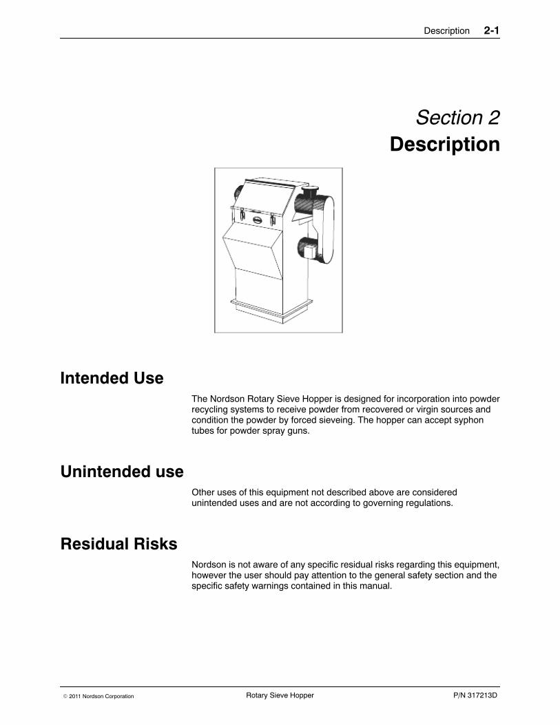
Intended UseThe Nordson Rotary Sieve Hopper is designed for incorporation into powderrecycling systems to receive powder from recovered or virgin sources andcondition the powder by forced sieveing. The hopper can accept syphontubes for powder spray guns.
Unintended useOther uses of this equipment not described above are consideredunintended uses and are not according to governing regulations.
Residual RisksNordson is not aware of any specific residual risks regarding this equipment,however the user should pay attention to the general safety section and thespecific safety warnings contained in this manual.

Description2-2
P/N 317213D E 2011 Nordson CorporationRotary Sieve Hopper
FeaturesPurpose designed for the recovery of organic powder coating materials, thesieve incorporates a feed hopper eliminating the need for interconnectinghoses.
Material from either recovered or virgin sources enters through a separatorand feeds into the sieve through a scroll, particles suitable for reuse passthrough the sieve mesh into a fluidised bed hopper, unusable material ispassed into a waste container for disposal.
The Rotary Sieve Hopper is made from powder coated Mild Steel. There isa large access cover allowing the inspection and loading of the coatingmaterial, the cover is electrically interlocked to the operation of the sieve.
An AC motor drives the sieve paddle indirectly, powder is retained in theRotary Sieve Hopper by utilising seals at both ends of the shaft.
Two sieve screens mounted on a carrier, can be quickly changed in case ofscreen damage by removal of one end of the sieve. The screens areavailable in a range of mesh sizes to cater for the customer requirements forthe quality of the recycled material.

Installation 3-1
P/N 317213DE 2011 Nordson Corporation Rotary Sieve Hopper
Section 3Installation
WARNING: Allow only qualified personnel to perform the following tasks.Follow the safety instructions in this document and all other relateddocumentation.
TransportTransport the unit so as to avoid damage. Use suitable packaging materialsand sturdy cartons. Protect the unit from exposure to humidity, dust andvibrations.
UnpackingCarefully unpack the unit to avoid damaging it. Check for damage causedduring transport.
Save packing materials for possible later use. Otherwise recycle or disposeof properly according to local regulations.
RemovingSwitch off the mains supply, then disconnect all electrical connections fromthe unit.
StorageSwitch off the mains supply, then disconnect all electrical connections fromthe unit.
DisposalDispose of properly according to local regulations.

Installation3-2
P/N 317213D E 2011 Nordson CorporationRotary Sieve Hopper
Setting Up the Unit
NOTE: Ensure that on completion of installation the sieve barrel ishorizontal.
1. All Rotary Sieves are provided pre drilled to take a standard NordsonPump Mount (28mm dia) on the sloping face of the hopper. On thesingle pump mount sieves, there is a maximum of 15 holes and on thedouble pump mounts, there is a maximum of 30 holes. Fit the pumpmounts according to the manufacturers instructions and fit the syphontubes so that the bottom of the tube is between 50 and 100 mm from thefluid bed.
2. Connect the output vent to either a Nordson type M4 recovery module,or using the optional vent adaptor kit, connect the vents to a suitableconnection within the recovery system. Please consult with your nearestNordson service centre for assistance in this matter.
3. Connect the separator inputs to the Nordson Transfer pumps, or otherpumps, at either the source of the recovered powder or at the source ofthe virgin powder. Ensure any unused inlets are fitted with a blankingcap.
4. If using a Nordson Level Control system remove the blanking plate andfit the level probe according to the product manual.
ElectricalWARNING: Allow only qualified personnel to perform the following tasks.Follow the safety instructions in this document and all other relateddocumentation.
1. Connect the motor and the access panel switch according to the circuitdetails shown in section 8.
2. Ensure that all electrical connections are tested in accordance withgoverning regulations before applying powder to the Rotary SieveHopper.
Pneumatic1. Fit a regulated air supply to the fluid bed. A minimum of two 6mm o/d
hoses should be used.

Operation 4-1
P/N 317213DE 2011 Nordson Corporation Rotary Sieve Hopper
Section 4Operation
WARNING: Allow only qualified personnel to perform the following tasks.Follow the safety instructions in this document and all other relateddocumentation.
Initial Startup1. Check the air supply at the fluid bed.
2. Check the setting of the motor overload in the control panel.
3. Noting the direction the arrow points on the pulley cover, remove thecover. Check that it is safe to start the sieve. Start and immediately stopthe motor and ensure that the rotation is according to the arrow shownon the end cover.
4. Start up the re--cycle system including the sieve according to theinstructions for each equipment, ensure that there are no leaks ofpowder from the transfer hoses. Leave to run for about one minute andstop the system. Open the access door and check that the powder isbeing sieved correctly.
5. Once a reasonable amount of powder has entered the hopper adjust thefluid bed air to give a gentle bubbling of the surface. It is recommendedthat the fluid bed air supply is maintained at all times to ensure that thematerial keeps in good condition.
NOTE: The best sieving action occurs when powder is fed to the hopper ata constant rate, this is particularly important for fine sieving. Overfeeding orsurges in the supply will cause excessive wear on the screens or a higherrejection rate of powder into the waste collector.
Daily OperationThe sieve is designed to stop and start automatically with the powder spraybooth and its recycle system. Virgin powder can be introduced from aNordson virgin feed system through the separator or it can be emptied fromthe box directly through the access door. Ensure that the machine isswitched off at the control panel and is left to rest for one minute beforeopening the access door.
WARNING: Breathing in certain airborne dusts (including finishingpowders) may be hazardous to health. Ask the powder manufacturer for aMaterial Safety Data Sheet (MSDS) for information. Use appropriaterespiratory protection.

Operation4-2
P/N 317213D E 2011 Nordson CorporationRotary Sieve Hopper

Maintenance 5-1
P/N 317213DE 2011 Nordson Corporation Rotary Sieve Hopper
Section 5Maintenance
WARNING: Allow only qualified personnel to perform the following tasks.Follow the safety instructions in this document and all other relateddocumentation.
Daily Maintenance1. Check the sieve screen for damage and correct tension.
2. Empty the waste bucket as required.
3. Check fluidisation of material in the hopper.
4. Clean the exterior of the sieve.
5. Verify the system is grounded
Yearly Maintenance1. Grease the sealed bearings, adding new grease ejects the old grease
while still maintaining the seal.
2. Check the tension of the motor drive belts.
3. Grease the motor bearings.
4. Check screens replace as necessary, note it is better to regularlyreplace the screen than have one wear out during operation.
Screen Replacement1. It is important that the sieve screen is correctly tensioned. Nordson can
supply a sieve tensioning tool for this purpose that applies lateral tensionto the cord in the circumference of one end of each hose.
2. The correct sieve tension varies with mesh size, finer meshes requiringless tension, the tension must always keep the mesh firm but notovertight.
3. After some running it may be necessary to re--tension the mesh due torelaxing of the mesh.

Maintenance5-2
P/N 317213D E 2011 Nordson CorporationRotary Sieve Hopper
Removal of Sieve Basket1. To remove the sieve basket first release the three star knobs at the
waste collector end of the sieve.
2. Remove the complete end of the sieve by pulling axially away from thesieve, ensure that the shaft is supported as it is released from thebearings to prevent damage.
3. Remove the sieve basket from the sieve through the end of the casing.
Removing Existing Sieve Screens1. Release the four securing clips.
2. Remove and dispose of the old screens.
Fitting New Sieve Screens1. Examine the replacement hoses for any transport or storage damage
before fitting.
2. Place the end of the sieve screen without the cord around it onto thecentre part of the sieve basket.
3. Secure the sieve screen to the basket noting the following, first makesure that the other end of the sieve screen when fitted over the baskethas sufficient area for the second clip to rest on, second that thematerial strips that run the length of the screen mesh are positionedunder a stay of the basket.
4. Pass the second clip over the sieve screen and fit the hose over theouter part of the basket.
5. Remove the three arms of the sieve tensioning tool.
6. Place the tensioning tool centrally over the end of the basket.
7. Refit the arms of the tension tool so that each one is located under thecord of the sieve screen.
8. Turn the central adjusting screw to increase the tension on the sievescreen.
WARNING: The tensioning tool is made for a range of mesh sizes and caremust be taken not to overstretch the finer meshes. New sieve screen shouldbe tensioned without overstraining. Too much tension will distort nylonmeshes.
9. When the correct tension is achieved place the sieve screen clipsagainst the arms of the tensioning tools and tighten to hold the mesh inplace.
10. Release the tension on the tensioning tool and remove the arms.
11. Repeat the process for the second sieve screen.
Maintenance 5-3
P/N 317213DE 2011 Nordson Corporation Rotary Sieve Hopper
Replacing Fluid Bed1. If the fluid bed should become damaged, usually to contaminations in
the air supply replace the fluid bed as follows.
2. Clean the hopper, removing all powder.
WARNING: The tensioning tool is made for a range of mesh sizes and caremust be taken not to overstretch the finer meshes. New sieve screen shouldbe tensioned without overstraining. Too much tension will distort nylonmeshes.
3. Remove all the fixing screws from the base of the hopper.
4. Using a lever, separate the upper part from the fluid bed and plenum.
5. Using two people lift off the upper part of the sieve.
6. Remove the fluid bed from the plenum and dispose of.
7. Clean the plenum and hopper surfaces of any remaining sealant.
8. Check the fitting of the new fluidising plate. Check the alignment of thefixing holes, if necessary drill holes to suit.
NOTE: The fluidising plate is fitted smooth side uppermost.
9. The fluidising plate is sealed using an acrylic sealant. On the plenum runa bead of sealant around the inside of the fixing holes on both sides.Place the fluidplate smooth side uppermost on the plenum. Run asecond bead of sealant around the inside of the fixing holes on theupper side of the fluid plate.
NOTE: Do not use a silicon based sealant.
10. Using two persons lift the sieve onto the plenum aligning the fixingholes. Secure with the fixing bolts, but do not overtighten them as thismay damage the fluid plate.
11. Remove any excess sealant.

Maintenance5-4
P/N 317213D E 2011 Nordson CorporationRotary Sieve Hopper

Troubleshooting 6-1
P/N 317213DE 2011 Nordson Corporation Rotary Sieve Hopper
Section 6Troubleshooting
WARNING: Allow only qualified personnel to perform the following tasks.Follow the safety instructions in this document and all other relateddocumentation.
Trouble Shooting GuideThis section contains troubleshooting procedures. These procedurescover only the most common problems that you may encounter. If youcannot solve the problem with the information given here, contact yourlocal Nordson representative for help.
Problem Possible Cause Corrective Action
Short Screen life Metal swarf in system Clean recycle system
Screen tension too great or tooslack
Tension correctly
Screen tension too great ortoo slack
Blind screen, that is holes in meshare blocked
Replace screen
Erratic overfeeding Adjust recycle system
Air leak on waste bucket Replace waste bucket seals
Incorrect screen tension Set screen tension correctly
Incorrect screen mesh size Check mesh size against recyclerequirements, change mesh size
Oversize material inhopper
Screen damaged Replace screens
Basket seals failed Replace seals
Waste bucket full Empty more frequently
Screen mesh size too large Check mesh size against recyclerequirements, change mesh size
Sieve Stops Overload operated Check overload settings and ambienttemperatureCheck paddle is free to rotate
Access door interlock operated Check operation of access doorinterlock

Troubleshooting6-2
P/N 317213D E 2011 Nordson CorporationRotary Sieve Hopper

Parts 7-1
P/N 317213DE 2011 Nordson Corporation Rotary Sieve Hopper
Section 7Parts
IntroductionTo order parts, call the Nordson Customer Service Center or your localNordson representative. Use this five-column parts list, and theaccompanying illustration, to describe and locate parts correctly.
Using the Illustrated Parts ListNumbers in the Item column correspond to numbers that identify parts inillustrations following each parts list. The code NS (not shown) indicatesthat a listed part is not illustrated. A dash (—) is used when the part numberapplies to all parts in the illustration.
The number in the Part column is the Nordson Corporation part number. Aseries of dashes in this column (- - - - - -) means the part cannot be orderedseparately.
The Description column gives the part name, as well as its dimensions andother characteristics when appropriate. Indentions show the relationshipsbetween assemblies, subassemblies, and parts.
S If you order the assembly, items 1 and 2 will be included.
S If you order item 1, item 2 will be included.
S If you order item 2, you will receive item 2 only.
The number in the Quantity column is the quantity required per unit,assembly, or subassembly. The code AR (As Required) is used if the partnumber is a bulk item ordered in quantities or if the quantity per assemblydepends on the product version or model.
Letters in the Note column refer to notes at the end of each parts list. Notescontain important information about usage and ordering. Special attentionshould be given to notes.
Item Part Description Quantity Note— 0000000 Assembly 11 000000 S Subassembly 2 A2 000000 S S Part 1

Parts7-2
P/N 317213D E 2011 Nordson CorporationRotary Sieve Hopper
Parts List
Front Elevation
2
3
4
5
6
7
8
1
10
9
1112
13
Figure 7--1 Front Elevation
Item Part Description Quantity Note1 -- 20--25MM JUBILEE CLIP; CYCLONE AR2 -- INLET CAP--PVC AR3 -- 8--INLET SEPERATOR; CYCLONE AR

Parts 7-3
P/N 317213DE 2011 Nordson Corporation Rotary Sieve Hopper
NoteQuantityDescriptionPartItem4 767320 HANDLE,HOPPER AR5 765440 SWITCH,CAM SAFE,END OPERATE AR6 768201 FITTING, DISTRIB, 1/4BSPM--2X6MM(PI) AR7 765406 BUCKET,WASTE,ROTARY SIEVE H200 AR8 765409 COVER,PULLEY,ROTARY SIEVE H200 AR9 769924 ARROW,DIRECTION AR10 765410 FLUID BED,R/SIEVE,720*540MM/5mm AR11 765427 GASKET,VENT AR12 769509 KNOB,STAR,M10 AR13 767140 FASTNER,ST/ST,PROTEX ARNS 765413 PLATE,BLANK,LEVEL PROBE,R/S H200 AR NSNS 769410 NUT,M4,BZP AR NSNS 769646 SCREW,M6x12,POSI PAN HD,CHROME AR NSNS 769413 WASHER,SPRING,M4,BZP AR NSNS 769442 WASHER,PLAIN,M8,BZP AR NSNS 769440 NUT,M8,BZP AR NSNS 769666 SCREW,M8x20,HEX HD,BZP AR NSNS 769614 SCREW,M4x10,POSI PAN HD,BZP AR NSNS 769462 WASHER,PLAIN,M12,BZP AR NSNS 769451 NUT,M10,NYLOC,BZP AR NSNS 769680 SCREW,M10x20,HEX HD,BZP AR NSNS 769421 NUT,M5,NYLOC,BZP AR NSNS 765417 MOTOR,1.5KW,3 PH,4 POLE,380/415V AR NSNS 765430 SEAL,ROT SIEVE HOPPER,GASKET AR NSNS 765426 GASKET,ROTARY SIEVE HOPPER AR NSNS 769663 SCREW,M8x15,HEX HD,BZP AR NSNS 765416 RING.SPACER,ROTARY SIEVE H200 AR NSNS 765411 LID,ROTARY SIEVE H200 AR NSNS 765408 COVER,FRONT,ROTARY SIEVE H200 AR NSNS 765415 PLENUM,ROTARY SIEVE H200 AR NSNS 765452 BODY,HOPPER,DOUBLE,R/SIEVE H200 AR NSNS 765459 PACKING CASE, ROTARY SIEVE AR NSNS 769923 LABEL,WARNING AR NSNS 769750 OBS: BOLT,M10x40 HEX HD,BZP AR NSNS 769902 LABEL,CE,H200 ROTARY SIEVE AR NSNS 769116 CABLE,SY, 6 CORE + E,1.0MM2,/MTR AR NSNS 769131 GLAND,10 WAY CONNECTOR AR NSNS 769023 CONNECTOR,HOOD,10 WAY,SIDE ENTRY AR NSNS 769027 CONNECTOR,INSERT,10 WAY,MALE AR NSNS 769026 CONNECTOR,INSERT,10 WAY,FEMALE AR NSNS 769025 CONNECTOR,HOUSING,10 WAY,REAR ENT AR NSNS 768251 TUBING,POLY,6MM OD,BLUE,/MTR AR NSNS 769000 ENCLOSURE,TERMINAL,PLASTIC AR NSNS 769132 GLAND, CABLE, 4--7MM AR NSNS 769112 CABLE,SY, 3 CORE + E,1.5MM2,/MTR AR NSNS 769107 CABLE,3183Y,3 CORE,0.75MM2,BK,/MT AR NSNS 768223 FITTING,Q/D,MALE,1/8BSP--6MM AR NSNS 768222 FITTING,Q/D,FEMALE,1/8BSP--6MM AR NSNS 769133 GLAND, CABLE 8--13MM AR NSNS 767215 SEAL,SIDE,SML,KNOCK--ON,MTR AR NSNS 769453 WASHER,SPRING,M10,BZP AR NS

Parts7-4
P/N 317213D E 2011 Nordson CorporationRotary Sieve Hopper
NoteQuantityDescriptionPartItemNS 769751 BOLT,M10x50,HEX HD,BZP AR NSNS 765418 PLATE,MOTOR MOUNTING,R/SIEVE H200 AR NSNS 769752 BOLT,M10x60,HEX HD,BZP AR NSNS 769422 WASHER,PLAIN,M5,BZP AR NSNS 767205 SEAL,1/4 IN.X1/2 IN.,/MTR AR NSNS 768900 SENSOR, PROXIMITY, MULTI--VOLTAGE, RE AR NS
NS: Not Shown
AR: As Required
Cross Sectional View - Metric
2
5
47
1
6
2
5
3
++
6
2
108
8
12
13
Figure 7--2 Cross Sectional View

Parts 7-5
P/N 317213DE 2011 Nordson Corporation Rotary Sieve Hopper
Item Part Description Quantity Note1 765490 SHAFT,ROT SIEVE,ST/ST,30MM DIA,IT,METRIC 12 765491 SEAL CARRIER,ALUM,ROT SIEVE,IT,METRIC 23 765492 WASHER,BRZ,30MM DIA,ROT SIEVE,IT,METRIC 14 765493 SCREW PADDLE ASSY,ROT SIEVE,IT,METRIC 15 765494 BEARING AND HOUSING,ROT
SIEVE,IT,METRIC2
6 765495 GASKET DIA. 30MM FOR IT ROTARY SIEVE 47 765407 CARRIER,SCREEN,ROT SIEVE H200 18 768207 FITTING, AIR, 90° , 6MM X 1/8 BSPM 29 765423 PULLEY,SIEVE,ROTARY SIEVE HOPPER 1NS 765419 PULLEY,MOTOR,ROTARY SIEVE HOPPER 1 requires item
76542010 765422 BELT,V,ROTARY SIEVE HOPPER 211 -- TAPER LOCK BUSHING 112 765448 SCREEN,300M,MIDI ROTARY,A/S--PAIR AR12 765446 SCREEN,145M,MIDI ROTARY,A/S--PAIR AR13 765425 CLIP,HOSE,SIEVE BASKET AR14 765428 KEY,ROTARY SIEVE HOPPER AR
AR: As Required
NS: Not Shown

Parts7-6
P/N 317213D E 2011 Nordson CorporationRotary Sieve Hopper
Cross Sectional View - Imperial
NOTE: See Figure 7--2.
Item Part Description Quantity Note1 765439 SHAFT,ROTARY SIEVE H200 12 765429 SEAL,CARRIER,ROTARY SIEVE H200,IMPERIAL 23 765441 WASHER,SPACER,ROTARY SIEVE HOPPER 14 765412 PADDLE & SCREW,ROTARY SIEVE,IMPERIAL 15 765424 BEARING+HOUSING,R/SIEVE,IMPERIAL 26 765426 GASKET,ROTARY SIEVE HOPPER 47 765407 CARRIER,SCREEN,ROT SIEVE H200,IMPERIAL 18 768207 FITTING, AIR, 90° , 6MM X 1/8 BSPM 29 765423 PULLEY,SIEVE,ROTARY SIEVE HOPPER 1NS 765419 PULLEY,MOTOR,ROTARY SIEVE HOPPER 1 requires item
76542010 765422 BELT,V,ROTARY SIEVE HOPPER 211 765421 BUSH,T/LOCK,SIEVE,R/SIEVE HOPPER 112 765448 SCREEN,145M,MIDI ROTARY,A/S--PAIR AR12 765446 SCREEN,145M,MIDI ROTARY,A/S--PAIR AR13 765425 CLIP,HOSE,SIEVE BASKET AR14 765428 KEY,ROTARY SIEVE HOPPER AR
AR: As Required
NS: Not Shown

Parts 7-7
P/N 317213DE 2011 Nordson Corporation Rotary Sieve Hopper
Specifications 8-1
P/N 317213DE 2011 Nordson Corporation Rotary Sieve Hopper
Section 8Specifications
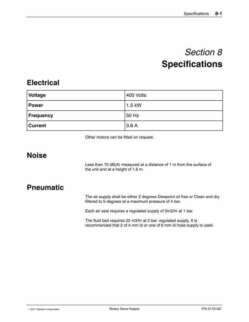
Electrical
Voltage 400 Volts
Power 1.5 kW
Frequency 50 Hz
Current 3.6 A
Other motors can be fitted on request.
NoiseLess than 70 dB(A) measured at a distance of 1 m from the surface ofthe unit and at a height of 1.6 m.
PneumaticThe air supply shall be either 2 degrees Dewpoint oil free or Clean and dryfiltered to 5 degrees at a maximum pressure of 4 bar.
Each air seal requires a regulated supply of 2m3/hr at 1 bar.
The fluid bed requires 22 m3/hr at 2 bar, regulated supply. It isrecommended that 2 of 4 mm id or one of 6 mm id hose supply is used.

Specifications8-2
P/N 317213D E 2011 Nordson CorporationRotary Sieve Hopper
Dimensions and Weight
Double Pump Mount
Weight: 135Kgs
Figure 8--1 Dimensions of DoublePump Rotary Sieve

Specifications 8-3
P/N 317213DE 2011 Nordson Corporation Rotary Sieve Hopper
Circuit Schematic
Figure 8--2 Circuit Schematic

Specifications8-4
P/N 317213D E 2011 Nordson CorporationRotary Sieve Hopper
Accessories 9-1
P/N 317213DE 2011 Nordson Corporation Rotary Sieve Hopper
Section 9Accessories

Accessories9-2
P/N 317213D E 2011 Nordson CorporationRotary Sieve Hopper
Magnetic Seperator
Item Part Description Quantity Note-- 765468 Magnetic Seperator Assembly, 14 Inlet: AR1 765455 Fabrication, Magnetic Seperator 12 765457 Magnetic Assembly 13 767140 Latch, St/sT 24 767162 Latch, St/St 25 769205 Seal --6 767332 Plugs, Blanking 147 769514 Clips, Jubilee 148 766617 Spigot, 50mm Outlet 1
Accessories 9-3
P/N 317213DE 2011 Nordson Corporation Rotary Sieve Hopper
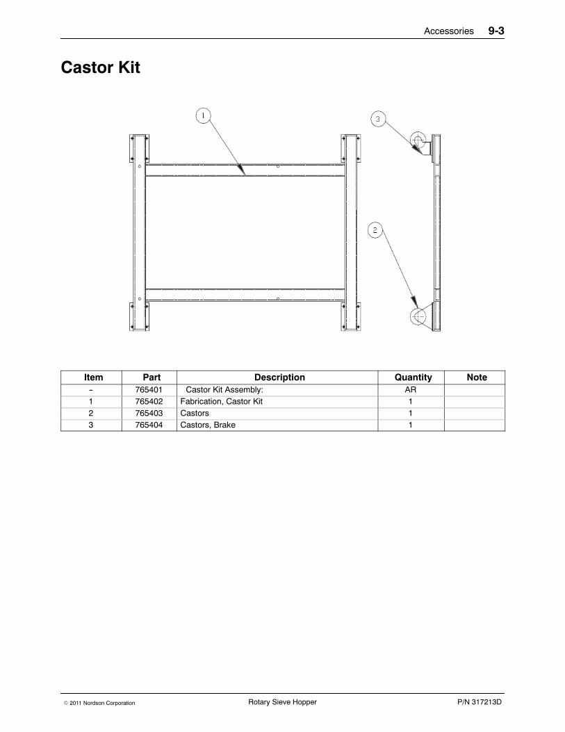
Castor Kit
Item Part Description Quantity Note-- 765401 Castor Kit Assembly: AR1 765402 Fabrication, Castor Kit 12 765403 Castors 13 765404 Castors, Brake 1
Accessories9-4
P/N 317213D E 2011 Nordson CorporationRotary Sieve Hopper
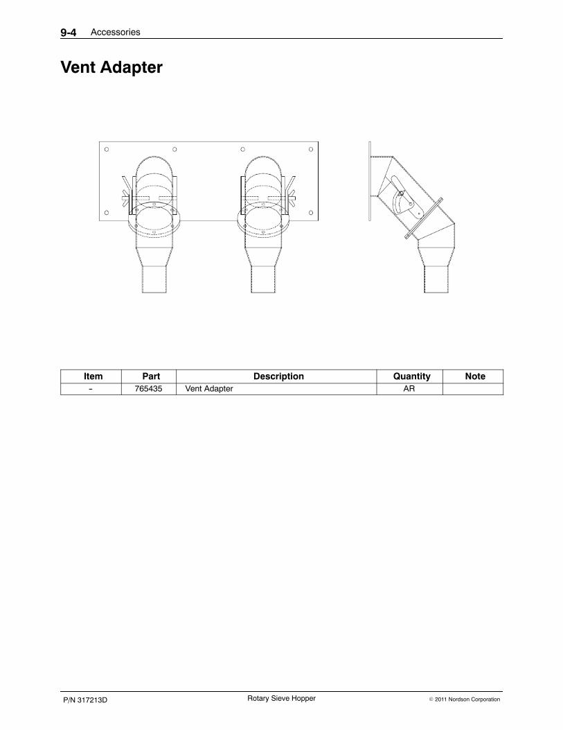
Vent Adapter
Item Part Description Quantity Note-- 765435 Vent Adapter AR
Accessories 9-5
P/N 317213DE 2011 Nordson Corporation Rotary Sieve Hopper