rotisserie construction - · pdf filebeen doing this car thing as long as i can remember, and...
TRANSCRIPT

Spinning My Tires is one man's view of the world of cars. Random thoughts, ideas and comments pop up here, all of them related to owning, driving and restoring cars. I've been doing this car thing as long as I can remember, and have enjoyed a great many car-related experiences, some of which I hope to share with you here. And I always have an opinion one way or another. Enjoy.
E-mails are welcomed--if you have thoughts of your own to share, please send them.
Additional Spinning My Tires editorials can be found on the Archives page.
Written by Matthew Harwood
6/25/04
Rotisserie Construction
Wow! This is the 20th editorial I've written for this site, and June 2004 marks the end of the second year of working on the Buick. Looking back, I see a lot of progress, but I also see that I'm not meeting many of my goals and the project is moving slower than I'd hoped. With that in mind, I decided that I needed to kick this thing into high gear and get some serious work done. That means removing the body. That means it's time for a rotisserie.
I decided to document the construction of my rotisserie here instead of in the restoration logs because it really isn't a restoration item. In addition, I'm really strapped for topics to write about right now, and since it's almost July, well, I figured I could merge the June and July Spinning My Tires editorials into one. I've been busy at work, traveling a lot, and it's been hard to find time to work on the car, let alone write. I also wrote my first article for the Buick Bugle, the BCA's national publication. You'll be able to see that in the July issue. So I haven't been slacking, but I have been quite short on time lately.
Like many of you, I looked all over the Internet for pricing and designs, and found a lot of options, from nice professional units to really cobbled-up amateur units that I wouldn't use to rotate my lawn mower. I also work in a machine shop that uses A LOT of steel--there are literally tons of steel sitting just 50 feet from my desk. I also need to practice my welding. Between those easy facts and the idea that I believe I can build a better rotisserie for less money, I set out to design my own.
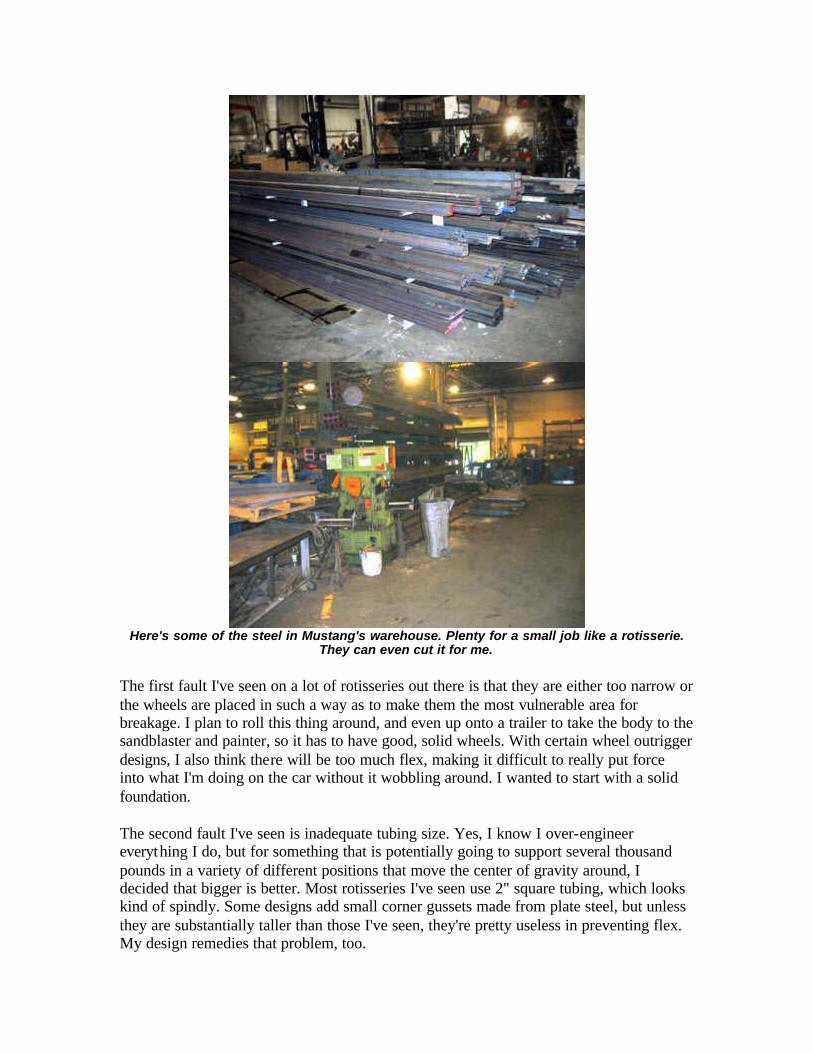
Here's some of the steel in Mustang's warehouse. Plenty for a small job like a rotisserie.
They can even cut it for me.
The first fault I've seen on a lot of rotisseries out there is that they are either too narrow or the wheels are placed in such a way as to make them the most vulnerable area for breakage. I plan to roll this thing around, and even up onto a trailer to take the body to the sandblaster and painter, so it has to have good, solid wheels. With certain wheel outrigger designs, I also think there will be too much flex, making it difficult to really put force into what I'm doing on the car without it wobbling around. I wanted to start with a solid foundation.
The second fault I've seen is inadequate tubing size. Yes, I know I over-engineer everything I do, but for something that is potentially going to support several thousand pounds in a variety of different positions that move the center of gravity around, I decided that bigger is better. Most rotisseries I've seen use 2" square tubing, which looks kind of spindly. Some designs add small corner gussets made from plate steel, but unless they are substantially taller than those I've seen, they're pretty useless in preventing flex. My design remedies that problem, too.

Initially, I wanted to use 4" square, 1/4" wall tubing, but the price of steel being what it is (about $0.72/lb.) makes that cost-prohibitive (that first design required over $800 in steel!). Instead, all of the tubing on my rotisserie will be 3/16" wall thickness, and range from 3- inch square down to 2- inch square along with some 3" x 2" rectangular tubing. The sizes I've chosen are common and easy to find, and will fit together without much extra effort. That really helps during assembly, especially since there are several slip joints and pivots on the thing.
The third fault is height and center of gravity problems. A rotisserie has to be high enough to fully rotate a car body, but not so high that it becomes top-heavy. This situation is exacerbated by wheels bolted under the braces or to the ends of the braces, which tends to raise the center of gravity. I designed my wheels to be "underslung" (anyone remember the American Underslung cars from the teens?), dropping the center of gravity considerably and freeing up valuable room in garages with low ceilings like mine. On a flat concrete or asphalt floor, ground clearance is not an issue.
Finally, there's tying the two ends together. Some do, some don't. I don't like the idea of the body being used as a structural part of the assembly. This can lead to some twisting or torque that can easily be prevented by running a beam between the stands. Again, I'm using thick steel here to make it as rigid as possible.
One feature I often see is height adjustability on the main upright using a hydraulic jack system. While this seems like a good idea in theory, it's important to remember that unless the centers of rotation on each end are on the exact same axis, the thing won't rotate very well. That's why I've left my rotation pins in fixed locations on the uprights and instead built the height adjustability into the brackets that actually attach to the car. With this setup, different heights between the front and rear of the body can be accommodated without affecting ease of rotation. I'll also add a pair of grease zerks in the pivot sleeve to keep it lubricated and easy to move.
To make my design strong, all the joints must be welded. Unfortunately, that means that my rotisserie will not be very portable, and with the thick steel, it'll be heavy. On the positive side, adapters can easily be made to convert it into a pair of heavy-duty engine or transmission or differential stands. I think that's a fair trade-off for strength. Check out the print below to get an idea of size and portability.
Click for full-size PDF (32k, 11" x 17")
I also had one of the structural engineers here at the shop take a look at my plans and materials. He ran a stress analysis on it and said that it should be good to at least 5000

pounds, probably more. The casters (from Caster Connection) I've spec'd are rated for 800 lbs. each, and there are 4 on each stand (fortunately, they're less than $15 each). I could probably rotate a complete car on this rotisserie, though I can't imagine why I'd want to. Still, it never hurts to have capacity you won't use, right?
Here's the complete materials list:
Quantity Length (in inches)
Description Notes
4 12 3" x 2" 3/16 wall rectangular tube rear wheel outriggers
2 24 3" x 2" 3/16 wall rectangular tube front wheel outriggers
2 32 3" x 3" 3/16 wall square tube front base tube 2 36 3" x 3" 3/16 wall square tube upright tube 2 48 3" x 3" 3/16 wall square tube rear base tube 4 24 2" x 2" x 1/8 wall square tube upright braces (45 degree cuts
(see print)) 2 6 3" x 3" x 3/16 wall square tube height adjustment sleeve 4 4 3" x 3" x 3/16 wall square tube width adjustment sleeves
2 48 2.5" x 2.5" x 3/16 wall square tube rotator cross piece
4 16 2.5" x 2.5" x 3/16 wall square tube rotator-to-body supports
2 24 2.5" x 2.5" x 3/16 wall square tube height adjustment tube
2 6 3" OD 3/16 wall DOM round tube rotator sleeve
2 12 2.5" OD 1/4 wall round tube rotator pin 1 10 x 10 1/2" steel plate front upright brace (see print) 1 1.5 x 3 1/4" steel plate height adjustment sleeve
gussets (see print)
8 N/A 4" polyurethane swivel casters Caster Connection part no. C3240-PU-S
4 N/A 1/4"-28 grease fittings lubricate rotating sleeve & pin
On the upcoming pages, I'll take you step by step through the construction and show you how I do it. I think it's the best design out there and plenty strong for any car you're likely to be working on.
7/8/04
Rotisserie Construction
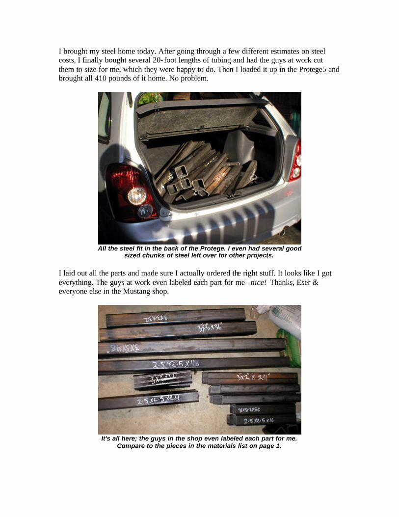
I brought my steel home today. After going through a few different estimates on steel costs, I finally bought several 20-foot lengths of tubing and had the guys at work cut them to size for me, which they were happy to do. Then I loaded it up in the Protege5 and brought all 410 pounds of it home. No problem.
All the steel fit in the back of the Protege. I even had several good
sized chunks of steel left over for other projects.
I laid out all the parts and made sure I actually ordered the right stuff. It looks like I got everything. The guys at work even labeled each part for me--nice! Thanks, Eser & everyone else in the Mustang shop.
It's all here; the guys in the shop even labeled each part for me.
Compare to the pieces in the materials list on page 1.

The first thing I did was start to clean up the ends of the steel where it had been cut. The rough edges would not only be difficult to weld satisfactorily, but were as sharp as razors. I used a sanding wheel on my die grinder to knock off the mill scale and rough edges so the surfaces would be clean. On pieces where the ends would be welded, I beveled the edges of the tubing so that I could get more weld surface area. One of the most important things I've learned about welding is that it is all about surface area. On structural welds in thick steel, it is critical to have enough metal to make several passes to get complete coverage and penetration, especially with a smaller welder like mine. I'm using .035 wire, which is about the thickest available for my small welder and recommended for structural steel this thick (3/16").
Beveled edges improve weld quality.
I laid out the main "T" of the base and shimmed it so that the pieces met perfectly square to each other, then tacked them together. I'm going to tack the whole assembly together so I can make any last-minute adjustments to the plan, then finish weld all the joints later.
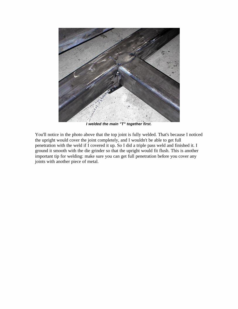
I welded the main "T" together first.
You'll notice in the photo above that the top joint is fully welded. That's because I noticed the upright would cover the joint completely, and I wouldn't be able to get full penetration with the weld if I covered it up. So I did a triple pass weld and finished it. I ground it smooth with the die grinder so that the upright would fit flush. This is another important tip for welding: make sure you can get full penetration before you cover any joints with another piece of metal.
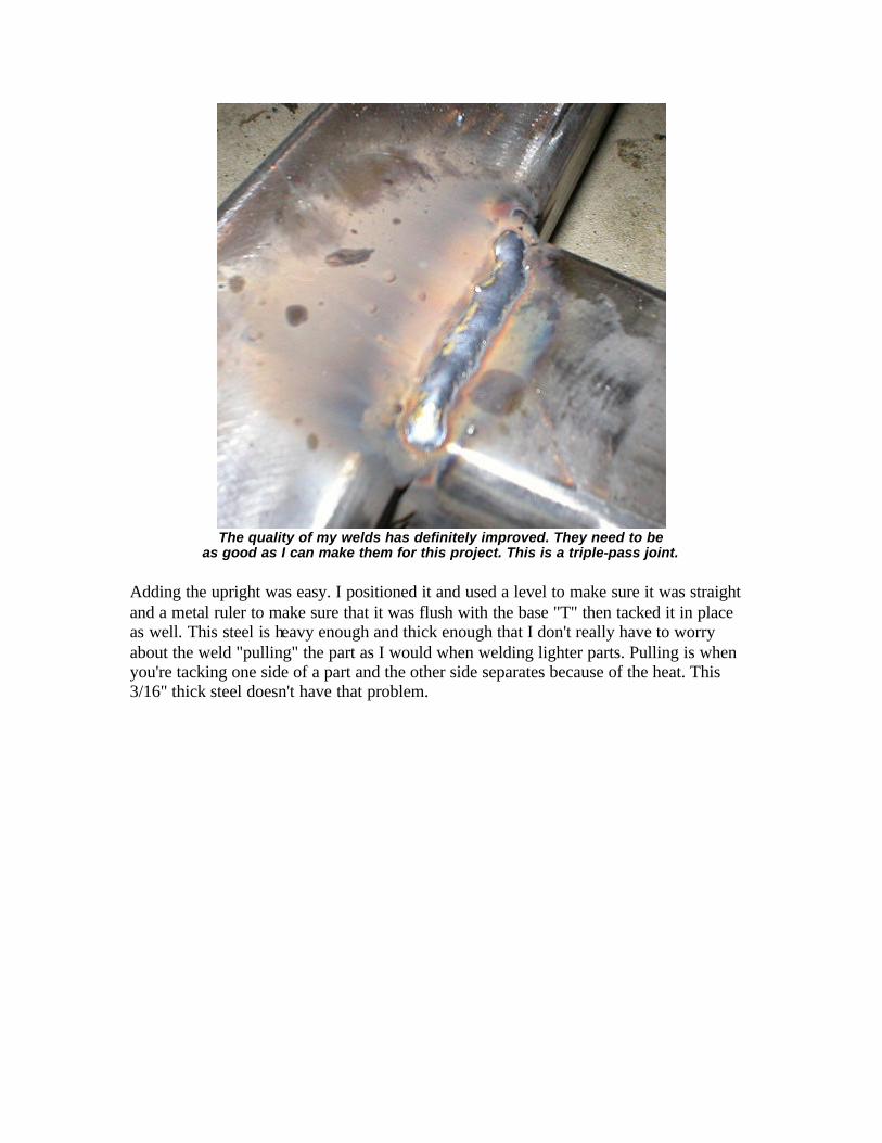
The quality of my welds has definitely improved. They need to be
as good as I can make them for this project. This is a triple-pass joint.
Adding the upright was easy. I positioned it and used a level to make sure it was straight and a metal ruler to make sure that it was flush with the base "T" then tacked it in place as well. This steel is heavy enough and thick enough that I don't really have to worry about the weld "pulling" the part as I would when welding lighter parts. Pulling is when you're tacking one side of a part and the other side separates because of the heat. This 3/16" thick steel doesn't have that problem.

Tacking the upright in place.
Attaching the outriggers for the rear wheels was next. These joints need to be ve ry strong since they'll be carrying all the weight of the assembly. Fortunately, these welds will be very strong because of the rounded corners of the tubing which makes a perfect trough for multiple passes with the welder. It should be plenty strong once it's all said and done. I just tacked them in place for now, however.
Outriggers tacked in place. On a structure like this, it is critical
to get a good weld on every single surface you can reach.
7/19/04

Next, I tacked the diagonal braces into place. With the 45 degree cuts on these braces, the relative squareness of your base will be immediately evident. If the braces don't line up on the upright, it isn't square. Fortunately, mine lined up perfectly, a testament to taking your time and making things right before you do any final welding.
All 3 diagonal braces meet at the same height, indicating that the
upright is perfectly square to the base.
The next step is probably the most difficult part of the whole job: cutting the "cradle" that the rotating sleeve fits in. I used my Sawzall to trim it close and finished it with a cylindrical die grinder bit. It is important to note that if you're using my design, carefully locate the rotating sleeve--it isn't quite half-way set into the upright, so don't make your cut too deep. Make it too shallow and gradually widen it with the die grinder to make a perfect fit.

Carefully cut your cradle area. Note that the cradle
is not quite equal to the radius of the rotating sleeve.
Before I tacked the sleeve in place, I placed a level on the base and leveled it using a few small pieces of sheetmetal. Once the base was level, I placed the level on the sleeve, leveled it and tacked it in place. Why is it so important to make sure everything is level? Since the sleeves on each end need to be on exactly the same plane, any tilt to it will induce bind into the apparatus. If there is any bind, it could add some torsional stress to the body once it is in place and make it more difficult to rotate. Making it as perfect as possible will give you a better chance of avoiding problems (this is a lesson well- learned in my days as a carpenter).
Once everything was where I wanted it, I set the entire assembly up on a makeshift welding table I set up in the shop. When doing any finish welding, I find it easier to position the work where I can make a flat weld at a comfortable level. Kneeling on a floor trying to make a weld work on a vertical surface is no way to get strong welds.

Setting work up at a comfortable level leads to quality welds.
Welding thick metal is going to be a challenge with any "hobby" level welder, mine included. Though it says that it will weld 1/4" metal, it won't do it for long without overheating, so plan your welds accordingly and don't just keep going--make sure you pause occassionally to let the welder cool off. I typically put my tack welds in the middle of joints, then finish weld on each side to minimize the time I spend with the welder going full tilt.
With such heavy metal, it isn't so critical to prevent heat build-up as it is with sheet metal, but if you are doing finish welds on one side of a piece with only a tack on the other, it is possible to pull the tack apart with the heat. Use caution and common sense.
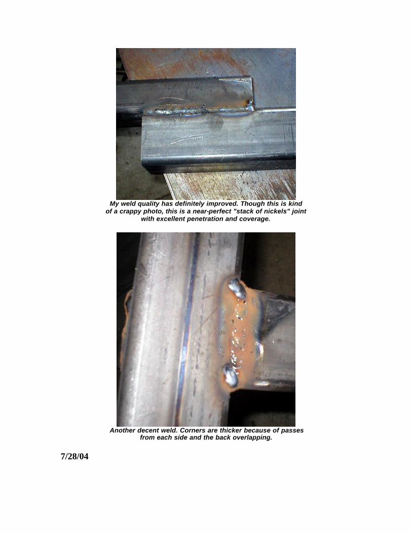
My weld quality has definitely improved. Though this is kind
of a crappy photo, this is a near-perfect "stack of nickels" joint with excellent penetration and coverage.
Another decent weld. Corners are thicker because of passes
from each side and the back overlapping.
7/28/04

I ran into a problem when I went to build the rotating assembly, specifically the pin that fits inside the sleeve. That's why I haven't done an update for a while.
When I bought the round tubing, the pin fit inside the sleeve easily. I believe the heat of welding must have distorted the sleeve to the point where the pin would not fit inside. I spent four days trying various ways of enlarging the sleeve, ranging from a cylinder hone to a sandpaper wheel to a diamond-tipped die grinder bit I borrowed from work. No dice. I couldn't believe how much the sleeve had changed size! Ultimately, I took the pins to work and had the guys in the machine shop take 0.030" off of each pin on the lathe. Result: perfect fit with a great surface for retaining lubricant grease.
Turning the pin diameter down slightly
made it fit perfectly in the sleeve.
I also used the sandpaper roll I purchased yesterday to smooth out the inner surfaces of the rotator sleeve to help it rotate properly. It left a really nice, smooth surface.
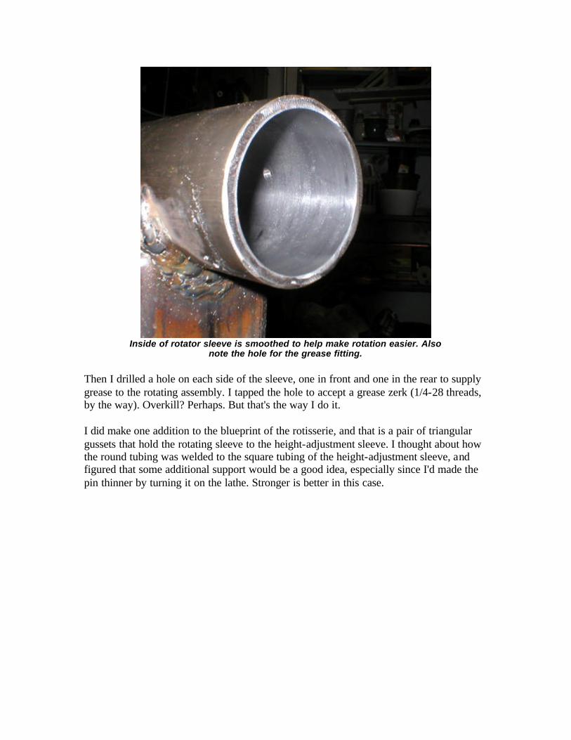
Inside of rotator sleeve is smoothed to help make rotation easier. Also
note the hole for the grease fitting.
Then I drilled a hole on each side of the sleeve, one in front and one in the rear to supply grease to the rotating assembly. I tapped the hole to accept a grease zerk (1/4-28 threads, by the way). Overkill? Perhaps. But that's the way I do it.
I did make one addition to the blueprint of the rotisserie, and that is a pair of triangular gussets that hold the rotating sleeve to the height-adjustment sleeve. I thought about how the round tubing was welded to the square tubing of the height-adjustment sleeve, and figured that some additional support would be a good idea, especially since I'd made the pin thinner by turning it on the lathe. Stronger is better in this case.

I'll be adding some triangular gussets between the round tubing and
the square height-adjustment sleeve (vertical piece on the right).
8/2/04
It's been a few days, and I ran into another problem. Despite three engineers plus countless well-wishers taking a look at my design, nobody noticed the one critical flaw:
I think the picture speaks for itself...

So I did the only thing I could: cut the forward brace off. I'll do a slight redesign on the forward brace and replace it with some gussets made from 1/2" plate.
The fix is in.
I also built the body bracket and drilled the height adjuster to hang it in place (which is how I found about the interference problem). I had so carefully designed the thing to clear the front diagonal brace, even at its lowest position, but didn't stop to think about what happened when it rotates. Duh.
I also added a collar and small gussets around the adjustment sleeve to keep it aligned and strong. The collar should also help retain the grease in the rotating mechanism. I'll add a second collar at the back that will be retained by set screws or a pin.

Collar and gussets.
I'll drill two mounting holes on each side of the adjuster sleeve to hold the body brace in place. My thought is to drill the holes in the body bracket at the appropriate heights for the Buick. In this way I can custom fit it to the car. Future projects will have their own holes drilled--the steel will be plenty strong to accommodate several sets of holes, and they may link at a variety of different heights in the future. I feel that since I'm not building a production line item and probably won't be restoring dozens of cars (or maybe...), putting a hole every two inches, for instance, probably wouldn't be as helpful.
For drilling the holes, I've found it's better to put the sleeve and the body bracket together at the appropriate height, clamp them in place, then drill through all four walls at once so they line up perfectly. Take your time with the drill--use a low speed and lots of lubricant (WD-40 or cutting fluid) and steady pressure. A drill press is ideal, but you can do it with a hand drill if you're careful.
I also smacked up the front end of Julia's TT by hitting a chunk of wayward truck tire in the middle of the highway. It took out the front bumper, all four grilles, the A/C condenser, the radiator and maybe an intercooler or two. Nice, eh? Best of all, the insurance company said it was my fault, since it was an object, not another vehicle. Rats...

8/5/04
I've solved the clearance issue by using 1/2" plate steel gussets instead of the diagonal tubular brace (I'll be updating the blueprint to reflect this change). However, I had to make an executive decision regarding strength vs. range of motion and chose to go with strength. While there is undoubtedly much more clearance for the rotisserie to rotate using a gusset instead of a brace, it isn't perfect. In order to clear the body brace completely at its lowest position, the gusset would have been much too small to do any good against flex. So I decided that the rotisserie will rarely, if ever, be used at its lowest position, at least not for rotating, and made the gusset large enough to handle whatever loads I throw at it.
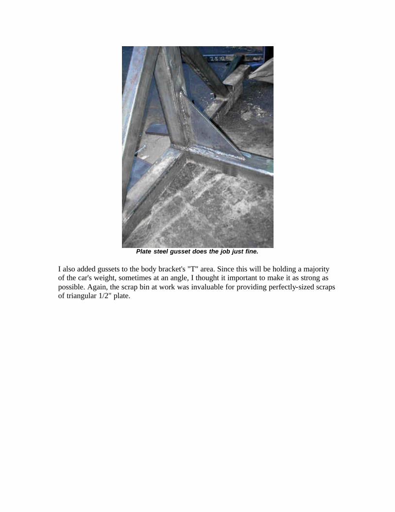
Plate steel gusset does the job just fine.
I also added gussets to the body bracket's "T" area. Since this will be holding a majority of the car's weight, sometimes at an angle, I thought it important to make it as strong as possible. Again, the scrap bin at work was invaluable for providing perfectly-sized scraps of triangular 1/2" plate.

Triangular gussets add strength without taking up too
much space on the horizontal bar.
I'm picking up the casters tomorrow and hope to have at least one complete unit ready for paint this weekend or next week. This one is close while the other still needs some final welding and sizing on the rotating sleeve.

Fixture one is almost finished.
9/5/04
We're in the home stretch now. I finished all the welding, attached the wheels, added a few gussets here and there, and drilled a lot of holes for adjusting the fit and angle. I used a drill press to accurately drill some holes in the rotator pin for locking it in position. I also added quite a few "lock bolts" in the pin, the the height adjuster and the body mounting brackets. While I don't trust these bolts alone to hold the body in position, they can certainly supplement the pins I'll be adding and will hold it in position while the pins are installed. Properly tightened, they seem to hold everything very solidly. Consider the pins safety insurance.

I drilled holes in the rotator pin for a pin to hold it at 0, 45 and 90 degrees.
Use a drill press for this process to ensure straight holes that line up properly. Also note the welded nuts for the "lock bolts" which are 1/2"-13 x 3/4" stainless.
Finished stand. Cosmo (black) and Lily (with scarf) liked to be
around during welding, so I had to be careful to lock them up whenever I struck a spark to protect their eyes. Remember this if you have kids
or pets...
Then I painted the stands. I prepped the surfaces by sanding them with my DA sander, then wiped it down with solvent to eliminate any oils or leftover WD-40 from the drilling processes. I used the same Rustoleum epoxy I used on the buffer stand. You'll also note that I brushed it on--after finding out what a hassle the paint gun is to clean, I'm not really

in the mood to use it unless absolutely necessary. I think it looks pretty good nonetheless...
Looks good in black, doesn't it?
9/23/04
It's finally finished! I added a few features at the last minute that I thought would be helpful in the future, such as lock bolts for the brace between the tripods to hold the brace solidly rigid. I also finished painting the thing, which is no small feat considering every time I put a coat of paint on anything, it falls over, bugs land it in, Julia decides to use the leaf blower to clean the driveway, whatever. I'll let the photos speak for themselves.
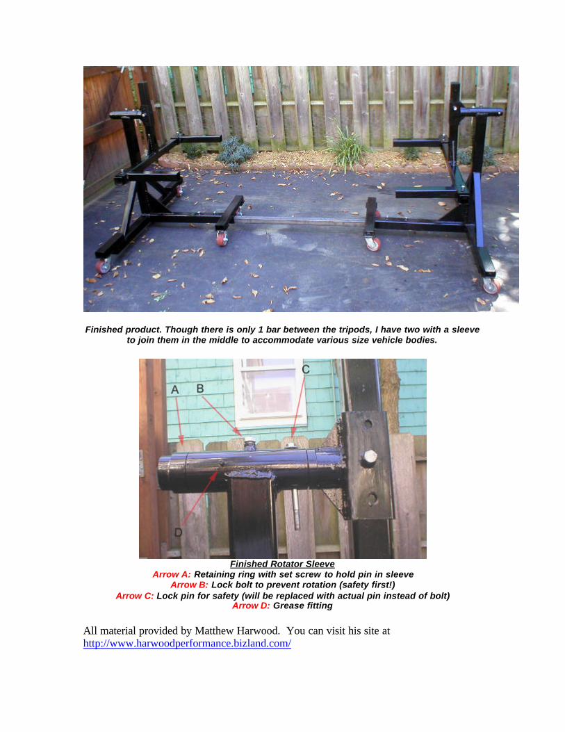
Finished product. Though there is only 1 bar between the tripods, I have two with a sleeve
to join them in the middle to accommodate various size vehicle bodies.
Finished Rotator Sleeve
Arrow A: Retaining ring with set screw to hold pin in sleeve Arrow B: Lock bolt to prevent rotation (safety first!)
Arrow C: Lock pin for safety (will be replaced with actual pin instead of bolt) Arrow D: Grease fitting
All material provided by Matthew Harwood. You can visit his site at http://www.harwoodperformance.bizland.com/
