rotor windage losses for lundell alternators by sol …€¦ · rations will produce different...
TRANSCRIPT

ROTOR WINDAGE LOSSES FOR LUNDELL ALTERNATORS
by Sol H. Gorland and Erwin E. Kempke, Jr.
Lewis Research Center
National Aeronautics and Space Administration
Cleveiand, Ohio
https://ntrs.nasa.gov/search.jsp?R=19720016402 2020-04-11T16:32:41+00:00Z


ABSTRACT
The Lundell alternator is being Investigated for
power system applications. At the high speeds re-
quired, power loss due to windage can become high
'tadrest,it in signficlant heating of the alternator.
'l'id.,4 IOHH nlust I)c lncorl_ra/ted In tim cooling
design. The velocity profiles expected in these
alternators are highly turbulent, and the Reynolds
numbers are well above the levels previously
reported; the available data could only be extra-
pointed. For this reason, a range of experimen-
tal data was generated to permit accurate calculation
of the windage .power loss for Lundell alternatordesign.
Windage tests were conducted on two concentric
rotor-stator configurations in ambient air, producing
Reynokts numbers as high as 100,000. Cylindricalrotors 10 and 12 inches in diameter were operated up
to 24,000 rpm, and an 8 inch diameter Lundell rotor
was operated up to 36,000 rpm. Gap-to-radius ratios
of 0.01, 0.02 and 0.04 were tested. Tests were also
conducted with axial slots machined on the stator sur-
faces to" simulate alternator winding slots.
Using the data obtained, a method was developed
to calculate the windage loss for any Lundell alternator
given the geometry and cavity conditions.
TIIE LUNDELL ALTERNATOR is a solid-rotor brush-
less machine that is being investigated for use in
future power system applications (1,2). * Since thereare no electrical or mechanical connections to the
solid rotor, its peripheral speed is limited only bythe ma,_imum stress of the rolor material. 'l'herefore_the I,uudell ;alternator provides maxhnunl I'eliabllitywlmn directly coupled to a high-speed turbine. Wind-
age losses become significant for large rotor diam-
eters, high speeds, and high-density high-viscosity
gases used in the rotor cavity for some applications.
In addition to the reduction in system efficiency, high
windage loss results in.significant heat generation Inthe alternator. This heat load must be included in
the alternator thermal design.
As shown in figure i, the rotor of a Lundell alter-
astor consists of two separate magnetic sections with
north poles on one section and south poles on the
other. The interpolar space is filled with a nonmag-
netic metal to obtain a smooth rotor. For purposes ofwindage analysis the typical Lundell rotor is con-
sidered to consist of a series of cones and cylinders.
Taylor, Vohr and Wendt (3, 4, 5) have studied
turbulent flow for concentric rots.ring cylinders with
Reynolds numbers (Re) as high as 40,000 (here Re
is defined using the gap as the characteristic dimen-
sion). These high Reynolds numbers, however, were
obtained using large radial clearances. Reference (6)
presents a preliminary study of windage losses for
concentric rotating cylinders with Re as high as
100,000 and gap-to-radius ratios of 0.01 to 0.04. This
is the range of gap sizes being considered for space
power alternators. These small magnetic gaps are
used to reduce field coil power, field coil leakage, and
rotor pole leakage thereby reducing rotor diameter
and weight. The choice of clearance must also allow
for other design constraints such as magnetic sprin_
rate (magnetic attraction force/unit eccentricity), syn-
chronous reactance, windage loss and cooling gasflow rate.
No specific Information was available on enclosed
rotating conical sections. The most appropriate in-
formation came from the studies of Daffy, etal., on
enclosed rotating disks (7,8).
To provide design engineers with information forthe prediction of windage losses, drag coefficient
versus Re data were generated for concentric cyltn-
*Numbers in pm entheses designate References
at end of paper.

,h,r_ A Lundcll-shaped rotor-housing configuration
was tested with gap-to-radius ratios of 0.01, 0.02
and 0.04. A correlation method was developed in
reference (9) to calculate the total windage loss for
this rotor. And this method has been used to predict,
with gJod ilgreement, the measured windage loss from
two dtffcrvntly sized Lundull rotors.
A PPAI{A TUS
The test apparatus, shown in figure 2, consisted
of a solid rotor (the Lundell rotor is shown here)
mo_mted on ball bearings lubricated with an air-oil
mist and a concentric housing (stator) attached to a
reaction-measuring support table. A more complete
description of the test support equipment is given in
reference (6).
ROTOR-tIOUSING CONFIGURATIONS - Dimen-
sions of the cylindrical and Lundell rotor and housing
configurations teated are shown in figures 3 and 4,
respectively. The rotors were made from a heat-
treated forging of a low-alloy vanadium steel and the
housings were aluminum. The housings were made
so that they could be removed without changing the
rotor alignment. The Lundell housing consisted of
five individual sections, corresponding to the changes
in cross-section, each split axia'lly for ease in dis-
assembly. All parts were doweled or keyed so that
alignment of the parts could be reproduced upon re-
assembly.
TESTS PERFORMED - The 10-inch- and 12-inch-
diameter cylindrical rotors were tested at speeds up
to 24,000 rpm for each of three gaps corresponding to
0.01, 0.02 and 0.04 gap-to-radius ratio. After each
teat of the smooth-surface 10-inch-diameter housing,
the housing was remachined with 60 equally-spaced
axial slots. Teats were run for several slot-depth
and -width combinations for each gap.
The Lundell rotor was tested at speeds up
36,000 rpm for each gap. Tests were performed on
the center cylindrical section of the housing and the
complete housing assembly. After completing tests
on the smooth-surface housing, the center cylindrical
housing section was remaehined with 60 equally spaced
axial slots to simulate alternator winding slots. These
slots were 0. 119-inch wide by 0. 010-inch deep.
Each test was rerun several times to verify re-
producibility of the data. AlI tests were per_rmed in
ambient air.
INSTRUMENTATION - Instrumentation consisted
of relational speed, torque and temperature sensors.
ltoiational speed was measured using a magnetic
pickup and 60-tooth gear combination on the shaft of
the drive system. The signal generated was sent to
a counter add recorded. Rotational speed was con-
trolh,d-and measured to within 0. t I)erc.ent.
'l_Ol'(|tll! in(_lla|lrl_nt(_ll[H w(_l'(i I11[1(|t} IIHilI_._ [h(l r_}ae-
finn lorque device shown in figure 2. Strain gages are
locatcd on four flexure arms so that they sense torque
about only one axis. This axis was made to coincide
with the axis of the rotor and its housing. Torque
developed about this sensing axis produced a propor-
tional strain. All tare torques remained constant
and were compensated for by calibration. The torque
unit was calibrated by hanging accurately known
weights from a calibration arm to produce known
torques. Calibration was accurate within 0.03-inch-
pound although measurements could be taken at less
than 0.01-inch-pound increments. The strain gage
output from the Wheatstone bridge circuit was meas-
ured on an IDVM - Integrating Digital Voltmeter.
Low-frequency vibration resulted in a 1 to 2 percent
oscillation in the signal output. Torque measure-
ments on the cylindrical rotors at 5,000 rpm and the
Lundell rotor at 8,000 rpm are approximately 5 per-
cent accurate, the.accuracy increasing with the speed.
All temperatures were measured using iron--constantan
type J thermocouples. Thermocouples were located
axially along the housing at the centerllne of the radial
air gap.
RESULTS AND DfSCUSSION
A typical Lundell alternator rotor consists of
conical and cylindrical sections. Windage is the
viscous loss in the annular gap between the roh_r and
the stationary outer housing. The frictional drag
force, F, may be expressed as
F = XA _pU2) (i)2
where
k : drag coefficient
A = surface area of rotor
p = density
U = surface speed of rotor
For a cylinder where
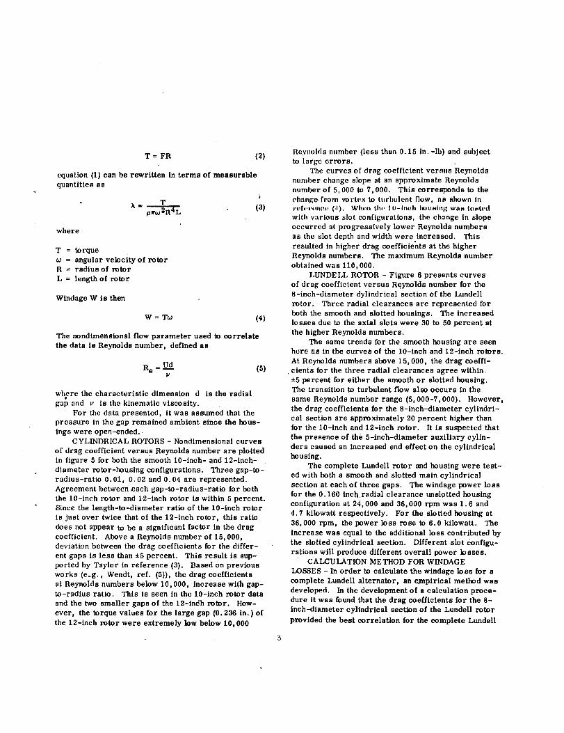
T = FR (2)
equation (I) can be rewritten in terms of measurable
quantities as
T_, '= _ (3)
p_'w-Lt -,.
where
T = torque
= angular velocity of rotorR = radius of rotor
L = length of rotor
Windage W is then
W = T_ (4)
The nondimensional flow parameter used to correlate
the data is Reynolds number, defined as
Re = Ud (5)P
where the characteristic dimension d is the radial
gap and v is the kinematic viscosity.
For the data presented, itwas assumed thatthe
pressure in the gap remained ambient since the hous-
ings were open-ended.
CYLINDRICAL ROTORS - Nondimensional curves
of drag coefficientversus Reynolds number are plotted
in figure 5 for both the smooth 10-inch- and 12-inch-
diameter rotor-housing configurations. Three gap-to-
radius-ratio 0.01, 0.02 and 0.04 are represented.
Agreement between each gap-to-radius-ratio for both
the 10-inch rotor and 12-inch rotor is within 5 percent.
Since the length-to-diameter ratioof the 10-inch rotor
is justover twice thatof the 12-inch rotor, this ratio
does not appear to be a significant factor in the drag
coefficient. Above a Reynolds number of 15,000,deviation between the drag coefficients for the differ-ent gaps is less than _-5 percent. This result is sup-
ported by Taylor in reference (3). Based on previousworks (e.g., Wendt, ref. (5)), the drag coefficientsat Reynolds numbers below 10,000, increase with gap-to-radius ratio. This is seen in the 10-inch rotor data
and the two smaller gaps of the 12-indh rotor. How-
ever, the torque values for the large gap (0.236 in.) ofthe 12-inch rotor were extremely low below 10,000
Reynolds number (less than 0.15 in.-lb) and subjectto large errors.
The curves of drag coefficientversus Reynolds
number change slope at an approximate Reynolds
number of 5,000 to 7,000. This corresponds to the
change from vortex to turbulent flow, as shown Inrq,ft,rtqtut_ (.I). WIl,_n tit,, 10-hu:h imtlslng was tested
with various slot configurations, the change in slope
occurred at progressively lower Reynolds numbers
as the slot depth and width were increased. This
resulted in higher drag coeffieiehts at the higher
Reynolds numbers. The maximum Reynolds number
obtained was 110,000.
LUNDELL ROTOR - Figure 6 presents curves
of drag coefficient versus Reynolds number for the
8-inch-diameter dylindrieal section of the Lundell
rotor. Three radial clearances are represented for
hoth the smooth and slotted housings. The increasedlosses due to the axial slots were 30 to 50 percent at
the higher Reynolds numbers.
The same trends for the smooth housing are seenhere as in the curves of the 10-Inch and 12-inch rotors.
At Reynolds numbers above 15,000, the drag coeffi-
cients for the three radial clearances agree within
• 5 percent for either the smooth or slotted housing.The transition to turbulent flow also occurs in the
same Reynolds number range (5,000-7,000). However,
the drag coefficients for the 8-inch-diameter cylindri-
cal section are approximately 20 percent higher thanfor the 10-inch and 12-inch rotor. It is suspected that
the presence of the 5-inch-diameter auxiliary cylin-
ders caused an increased end effect on the cylindrical
housing.
The complete Lundell rotor and housing were test-
ed with both a smooth and slotted main cylindrical
section at each of three gaps. The windage power loss
for the 0. 160 Inch radial clearance unslotted housing
configuration at 24,000 and 36,000 rpm was 1.6 and
4.7 kilowatt respectively. For the slotted housing at
36,000 rpm, the power loss rose to 6.O kilowatt. The
increase was equal to the additional loss contributed by
the slotted cylindrical section. Different slot configu-
rations will produce different overall power losses.CALCULATION METHOD FOR WINDAGE
I._SSES - In order to calculate the windage loss for a
complete Lundell alternator, an empirical method was
developed. In the development of a calculation proce-
dure it was found that the drag coefficients for the 8-
inch-diameter cylindrical section of the Lundell rotor
provided the best correlation for the complete Lundell

rotor using the available test data. It must be noted
however, that for purely cylindrical windage calcu-
lattons the 10- and 12-inch drag coefficient, should be
used.
The empirical method developed to calculate the
I_)1'1l I,nnd(_ll-nDior wlndag_ loe_cs lrcalN the conical
_cclb.JnH 'IH cyllud(,l'H hnvlng Iilll_lmetl,r(,(ltl;llIx)the
miller conlcul-section diameter, a length equal to the
length of the conical surface and a gap equal to the
clearance in the auxiliary-cylinder section. Windage
from each of the cylindrical sections is then calculated
using equations (3) and (4) with the drag coefficients
found from the 8-inch-diameter cylindrical section.
The drag coefficients are obtained by calculating the
Reynolds number ,in that section and then using the
curves in figure 6. A comparison between the meas-
ured and calculated values is given in table 1. The
results calculated are within 10 percent of the experi-
mental values.
To vcrify the applicability of this calculation
method, the measured windage losses of two other
Lundell alternators were compared. In reference (10)
n three-phase 120/208-volt Lundell alternator with.
an output rating of 14.3 kilovolt-ampere and a
0.75 lagging power factor was tested at 36,000 rpm.
The major diameter of this rotor was 3.3 inches.
The test points were obtained using krypton in the
zx)tor cavity at several presto|re levels. Figure 7
shows the measured power loss for this alternator
and the calculated loss as a function of cavity pres-
sure. Good agreement is found with the higher-
pressure test data and the deviation at the low-cavity-
pressure point is within the experimental uncertainty
for the low torque value recorded.
The other Lundell rotor used in the correlation
was tested by AiResearch Manufacturing Company as
part of a NASA contract. This rotor had a major
diameter of 6.58 inches and was operated in air at
24,000 rpm over a range of pressure levels. Figure 6
compares the measured and the calculated windage
losses. The results calculated are within 8 percent
of the experimental values for the complete range of
operating pressures.
SUMMARY
Three rotors, a 10-Inch- and 12-inch-diameter
cylinder and an 8-Inch-diameter Lundell-type rotor
were operated within stationary concentric hous-
ing. Three gaps were used f_r each rotor, corre-
(:._ponding to approximately 1, 2 and 4 percent of
the lvtor radius. The center cylindrical eectlon of
the Lundell housing was tested with a smooth surface
and with axial slots to simulate alternator winding
slots. It was found that power loss for the slotted
.Inllodary cylindrical (simulated armature) housing
(.onflgurlltlun_ el)crating in the turbuhmt flow regime
was 30 to 50 percent higher than for the smooth hous-
ing. For concentric cylinders, the range of Reynolds
number was extended to 100,O00. Using the data
obtained, a method was developed to calculate the
windage loss for Lundell alternators.
REFERENCES
1. R. E. English, "Technology of Nuclear-
Brayton Space Power Systems, " Presented at Z971
American Nuclear [-oeiety Meeting, Miami, Fla.,
Oct. 17-21, 1971.
2. D. C. Guentert and R. L. Johnsen, "Predicted
Performance of a 15-86 kW Reactor Brayton Power
System over a Range of Operating Conditions, " Pre-
sented at the IECEC, Boston, Mass., Aug. 3-5, 1971.
3. G. I. Taylor, "Fluid Friction Between Rotati_g
Cylinders. I - Torque Measurements, " Prec. Roy.
Soc. (London), Ser. A, eel. 157, no. 892, De('. 2,
1936, pp. 546-564.
4. J. Vohr, "Experimental Study of Superlamina_
Flow Between Noneoncentric Rotating Cylinders, "
NASA CR-749, 1967.
5. F. Wendt, "Turbulente _rSmungen Zwlschen
Zwei Rotierenden Konaxialen Zylindcrn, "Ing.-Archly.,
eel. 4, no. 6, Sept. 1933, pp. 577-595.
6. S, H. Gorland, E. E. Kempke, .h'., _md
S. Lumanniek, "Experimental Windage Losses for
Close Clearance Rotating Cylinders in the Turbulent.
Flow Regime, " NASA TM X-52851, 1970.
7. J. W. Daily and R. E. Nece, "}toughnes_ and
Chamber Dimension Effects on Induc,.d Flow :too
Frictional Resistance of Enclosed Relating _)i_ks, ""
Tcch. Rep. 27, Massachusetts Inst, Tech. _ _vdro-
dynamics Lab., May 1958.
8. J. W. Daily, W. D. Ernst, and V. V. Asbcdian,
"Enclosed Rotating Disks with Superposed "Fhroughflow:
Mean Steady and Periodic Unsteady Characteristics of
the Induced Flow," Rep. 64-16, Massachusetts Inst.
Tech., ttydrodynamlcs Lab. (AROD-2500-2,
AD-443060), Apr..1964.
1,
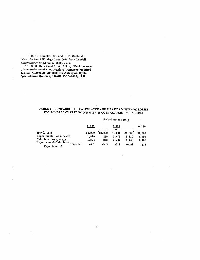
9. E. E. Kempke, Jr. and S. H. Gorland,"Correlation of Windage Loss Data for a LundellAlternator," NASA TN D-6650, 1972.
10. D. S. Repas and R. A. Edkin, "PerformanceCharacteristics of a 14.3-Kilovolt-Ampere Modified
Lundclt Alternator Jor 1200 Hertz Brsyton-CycleSpace-Power Systems," NASA "IN D-540_, 1909.
TABLE 1 - COMPARISON OF CALCULATED AND _IEASURED WINDAGE LOSSES
FOR LUNDELL-SHAPED ROTOR WITH SMOOTH CONFORI_HNG HOUSING
Radial air gap (in.)
o.o3.._..._9
Speed, rpm 24,000 _2,000
Experimental loss, watts 1,819 259Calculated loss, watts 1,894 278E_perimental-C alc ul ated ' percent -4.1 -9.3
Experimental
o.o8.__._o
24,000 36,000 24,000
1,675 5,110 1,5931,743 5,140 1,485
-5.9 -0.58 6.8


NORTH POLE -, ,-NONMAGNETIC SEPARATOR
Figure 1. - lypical Lundell solid-rotor.
_ _ LUNDELI.ROTOR
=AIR-OIL .... __-MIST
:LEXURE
Figure 2. -Windage testapparatusfor Lundell-typerotor.
C-70-2639

D L
iO.O01 9.99OIZ.O05 5.9OO
____ FOR 10" _OR 12"
•100 .116.200 .2Yo
Figure 3.- Cylinddca_ rotorand housingconllguratlons.
0,01
A GAP-RADIUSRATIO
0.03g 0.01.080 .02
.160 .l_
w20 '1.5
Rgure 4. - Lundell rotor aria houslng configuration-

GAPROTORGAP/RADIUSo 0.056512" 0.01z_.116 12" .02
2F o .236 12" .04| o .04g I0" .Ol
IO-2F _o o v .100 IO" .02BF : %" o" o .200 1O" .04
DRAG 6F ° °.::Dof(>,.COEFFICIENT 4F _ _£_ _%e2
10-3 _LLI, I,I J _ !_!__2 4 6 8103 2 4 6 8 2 4 6 810/
REYNOLDS NUMBER
Figure5. - Dragcoefficientfora rotatingcylinder
in a smoothstationarycylindricalhousing.
DRAGCOEFFICIENT
RADIAL GAP BETWEEN HOUSING GAP/
STATORAND ROTOR, RADIUScm (in.)
o 0.09g (0.039) SMOOTH 0.01[] ,ogg (.039) SLOI'rED .Ol
o .203 (.080) SMOOTH .02.203 (.080) SLOTTED .02
o .406 (.160) SMOOTH .04l> .406 (.160) SLOTTED .04
10-2 o o
_ o _o% o_ _ % .SLOTTED
4_ eo_/_;, ," DATA
L SMOOTHI0- _, L,zd __
2 4 6 8103 2 4 6 8104 2 4 6 B
REYNOLDS NUMBER
Figure6. - DragcoefficientasfunctionofReynoldsnumber forrotatingcylinderin smoothand
slottedstationaryconcentrichousings.Rotor
diameter,20.32centimeters(8in.);rotorlength,10.16centimeters(4in.);slotdepth,O.025centi-meter(0.010in.)

r-.-,,0c_,,,D
!
WINDAGE
LOSS,
W,
WATTS
700----
600--
500--
400--
3OO
2OO
100
o EXPERIMENTAL (REF. 10) o
I I 1 I10 20 _) 40CAVITY PRESSURE, NICML
J l 1 J I I0 10 20 30 40 50
CAVITY PRESSURE, PSIA
Figure l. - Lundell alternator windage losses in krypton at
36000 rpm compared to analytical results.
WINDAGE
LOSS,kw
4-
o EXPERIMENTAL /
3
2
1
I
0 I0 20 30 40 50 60
CAVITY PRESSURE. PSIA
Figure 8. - Lundell alternatorwlndage losses in air at
2404)0rpm compared to analyticalresults.
NASA-Lewis-Com'l