rotordynamic validation of a twin rotor-bearing system...
TRANSCRIPT
1
Rotordynamic Validation of a Twin Rotor-bearing SystemConsidering Gyroscopic Forces and Bearing Dynamicswith a Multibody Formulation: Application to a Geared
UHBR Gas TurbineT. S. Müller and H. Hennings, Institute of Aeroelasticity, German Aerospace Center,
Bunsentraße 10, 37073, Göttingen, Germany
Abstract—A rotordynamic study for an engine with an ultra-high bypass ratio (BPR=17) was performed using a multibody (Simpack)and a finite element (Ansys) description. The previous validation based on an analytical system of a coaxial counter rotating twinrotor model was performed to legitimize the use of Simpack and the methodological approach, which included the modal reduction offinite element bodies and their integration in the multibody description. Therefore the eigenfrequencies as a function of the rotationalspeed and the unbalance respond due to eccentricity were compared. The same methodology was then applied to the UHBR engine.Performing an evaluation of the critical speed map, Campbell diagram and an unbalance respond analysis to identify the systembehavior. By examining the system respond due to an unbalance force the need of a full modal description of the rotating parts withrespect to a suspension point of the complete engine was shown.
NOMENCLATURE
= Matrixx,y = Translational Coordinatesϕ = AngleM = Mass MatrixC = Damping MatrixK = Stiffness MatrixG = Gyroscopic MatrixF = Forceρ = Densityn = Rotational Speed Ratiok = Stiffness Parameterd = Damping Parameterω = EigenfrequencyΩ = Rotational Veclocitymud = Mass UnbalanceLP = Low PressureHP = High Pressure
Subscriptsd = Diskr = Rotorshaftn = nth-Elementb = Bearings = Systemx,y = Axis of Rotation˙ = Velocity¨ = Acceleration
1 INTRODUCTION
TO meet the growing demands for air travel in majoreconomic areas and thus increase the capacity limits, it
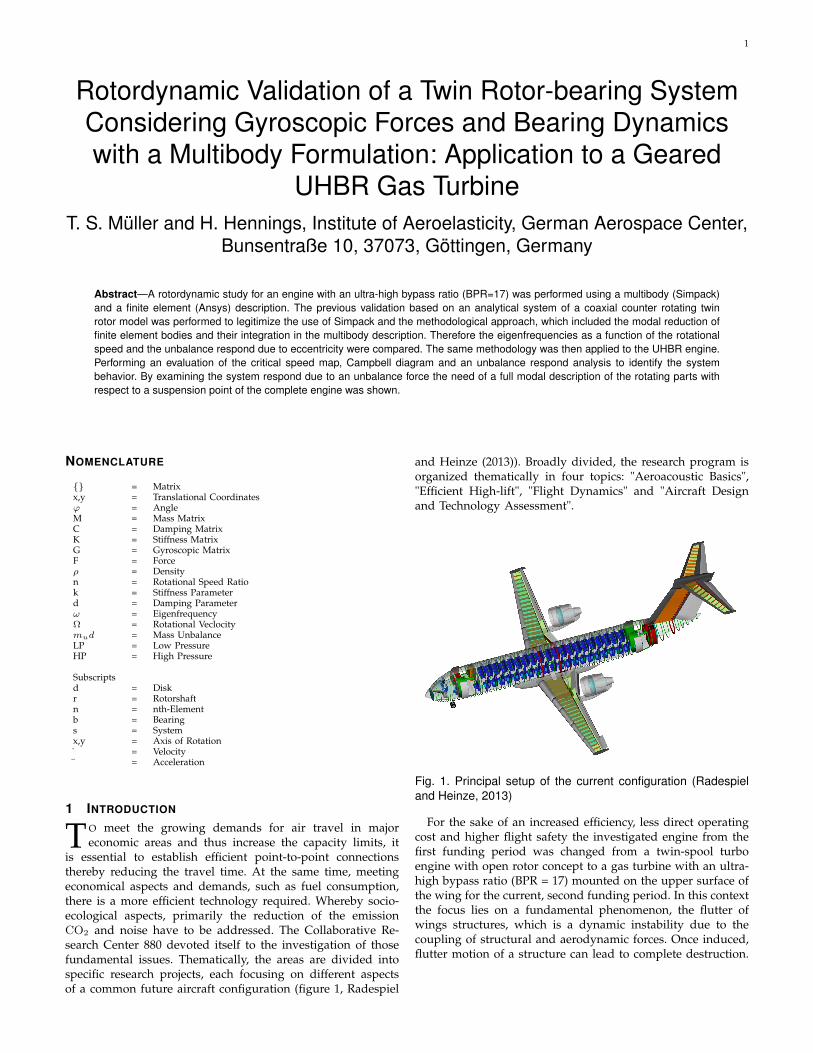
is essential to establish efficient point-to-point connectionsthereby reducing the travel time. At the same time, meetingeconomical aspects and demands, such as fuel consumption,there is a more efficient technology required. Whereby socio-ecological aspects, primarily the reduction of the emissionCO2 and noise have to be addressed. The Collaborative Re-search Center 880 devoted itself to the investigation of thosefundamental issues. Thematically, the areas are divided intospecific research projects, each focusing on different aspectsof a common future aircraft configuration (figure 1, Radespiel
and Heinze (2013)). Broadly divided, the research program isorganized thematically in four topics: "Aeroacoustic Basics","Efficient High-lift", "Flight Dynamics" and "Aircraft Designand Technology Assessment".
Fig. 1. Principal setup of the current configuration (Radespieland Heinze, 2013)
For the sake of an increased efficiency, less direct operatingcost and higher flight safety the investigated engine from thefirst funding period was changed from a twin-spool turboengine with open rotor concept to a gas turbine with an ultra-high bypass ratio (BPR = 17) mounted on the upper surface ofthe wing for the current, second funding period. In this contextthe focus lies on a fundamental phenomenon, the flutter ofwings structures, which is a dynamic instability due to thecoupling of structural and aerodynamic forces. Once induced,flutter motion of a structure can lead to complete destruction.

2
Therefore there is a need for a precise tool for an accuratestability analysis conducting the preliminary aircraft designand thus providing the opportunity to be able to interveneconsciously in the process of development. On that accountthere is a reduced order model (ROM) for flutter predictionswith a nodal approach developed, (Krukow and Dinkler, 2014).Due to the large rotating masses it is assumed that the meredescription of the engine as a mass point is insufficient inorder to capture its influence on the wing structure. Therefore amodel of the overall dynamics of the engine has to be enclosedin the ROM, including gyroscopic and centrifugal forces andalso forces induced by the thrust vector causing the structureto stiffen and change its modal characteristics, (Waitz andHennings, 2015). Hence the modeling of the UHBR engineis approached in a hybrid way. For that reason a multibodyformulation with the tool Simpack, and the modal reducedFE bodies, created with the FEM tool Ansys, after the Craig-Bampton method (Craig and Bampton, 1986) by the use of thesubstructure technique, were utilized.
The hybrid use of multibody systems in combination withfinite element structures provides the potential to describe theglobal behavior in moving reference systems with regardinglarge deformations and the coupling of multiple kinematicchains of the entire engine and the connection to the wing.Furthermore the FEM interface enables the capturing of theelastic behavior of the rotor structures and the change intheir own behavior by stiffening effects due to centrifugal andgyroscopic effects by importing their modal description. Sincethe calculation of the flexible body takes place under distinctivecentrifugal forces, it is necessary to verify the general de-scription of this particular multibody system with establishedprograms to a simple system with analytical solutions. Besidesthe necessity for accuracy the numerical effort needs to be keptto a minimum of complexity. Therefore the amount of degreesof freedom for the built up of the UHBR model needs to beoptimized.In order to meet these requirements and legitimize the pro-cedure a model for validation is needed. For this purpose,an adequate system was presented by Ferraris et al. (1996), acoupled dual rotor system, to work as a reference system withanalytical results. Due to the simplicity of the model it servedas an optimization system, in a modified form, for startupbehavior (Fei et al., 2013). Additionally (Chiang and Hsu, 2004)investigated the influence of the rotational speed ratio on thecritical speed. Accordingly it is a reliable and well-studiedsystem which serves as a good validation model. Consequently,the prior aim of this paper is to model this simple unbal-anced coaxially mounted counter-rotating twin-rotor system inSimpack and Ansys. The rotor dynamic analysis provides thenatural frequencies taken as a function of rotational speed inform of Campbell diagrams and the response behavior dueto an unbalance excitation considering tumbling behavior isinvestigated. The validation criterion lies in the accuracy ofthe modal description. It legitimatizes the use of Simpack andserves as a preparation for the methodology. Since there havenot been any investigations of UHBR engines with multibodyformulation the second aim of this paper is the modeling of ageared twin-shaft UHBR engine considering non-linear bear-ing dynamics in Simpack using the sub modeling technique.Finally a full rotordynamic analysis of the system is carried out,including a critical speed map, Campbell diagram, unbalanceforce and the behavior of the complete system on a startup.
2 DYNAMICS OF ROTATING STRUCTURES
To study rotor dynamic effects a typical system consists of anarbitrary number of rotor disks connected to a shaft whichrotates with an angular velocity Ω and is mounted on discretebearing which withstand the forces, (Gasch et al., 2005).
2.1 Single Rotor - Governing Equations
O
Y
Z
X
Ω
ϕ x
ϕ y
Fig. 2. Single rotor model (Laval rotor)
Figure 2 shows an elementary rotor-bearing system, a socalled Laval rotor. It only consists of a single rotating shaftwith a single mounted disk. The model is considered as a 2Dproblem preliminarily only taking the lateral displacementsinto account. The shaft is considered flexible and the disk isassumed to be a rigid body. Hereafter the equations of motionare explained.
2.1.1 Rigid DiskThe nodal coordinates for the center of the disk, representedby the following equation:
ud = xd, yd, ϕdx, ϕdy (1)
neglecting the displacement in the direction of the rotationalaxis. Under the assumption of a rigid connection to the rigiddisk, the equation of motion can be described as:
[Md]ud+ [Gd]ud = F d (2)
The total force imposed on the shaft consists of the inertia andthe gyroscopic forces.
2.1.2 Flexible ShaftAssuming the rotor consists of n finite elements:
ur = xrn, yrn, ϕrx, ϕry (3)
The equation for the rotor is given by,
[Mr]ur+ ([Gr] + [Cr])ur+([Kr]− [Kr
c ])u = F r (4)
whereas inertia, gyroscopic, damping and stiffening forces aretaken into account.
2.1.3 Bearing ForcesConsidering the bearing behavior to be non-depended of therotational velocity Ω the bearing forces obey the governingequation of the following form:
[Cb]ub+ [Kb]ub = F b (5)
For the application in the second part of this work thebearing coefficients vary with the rotational velocity Ω.

3
2.2 System Equation of Motion2.2.1 Single Rotor SystemBringing together component wise the formulation of eq. 2 -eq. 4, this leads to the following formulation:
[Ms]us+ ([Gs] + [Cs])us (6)
+([Ks]− [Ksc ])u = F s
2.2.2 Dual Rotor SystemTo achieve the equation of motion for the entire dual rotorsystem (figure 3) one must couple the equations of the twosubsystems into the following form:
[Mr1 0
0 Mr2
][ur1
ur2
]+
[Gr1 0
0 Gr2
][ur1
ur2
]+[
Kr1 −Kr1c 0
0 Kr2 −Kr2c
][ur1
ur2
]=
[F r1
F r2
]+ Fib + Fb (7)
Corresponding to eq. 7 the coupling of the two systemsoccurs by the inter bearing force Fib + Fb (eq. 5) at the jointlocation C of both rotors (figure 3).
3 SOLUTIONS OF THE SYSTEM EQUATIONS
The key aspect of this work is to provide a fully modaldescription of the UHBR for the mentioned ROM, (Krukow andDinkler, 2014). Thus the eigenvalues of the rotational systemhave to be determined at certain operation points.
3.1 Critical SpeedThe critical speed corresponds to the natural frequency of thestructure. Hence it then occurs when the excitation frequencyequals the natural frequency. To determine the critical speedthe homogeneous form of the eq. 6, respectively eq. 7 needsto be solved. The dynamic equation of the simplest form of anundamped rotor can be written as:
[Ms]us+ [Gs]us+ [Ks]u = 0 (8)
The solution of eq. 8 is an eigenvalue problem expressed bythe form:
U = Φejλt with λ = αω (9)
Inserted into eq. 8 this leads to the new eigenproblem
([Ks]− λ2[Ms])Φ = 0 with [M
s] = [Ms]− j 1
α[Gs] (10)
Depending on the respective reference system one has totransform the obtained results by Appendix B.
4 VALIDATION DUAL ROTOR
4.1 Rotordynamic ModelingFor the purpose of validation, an analytical model of twoco-axial counter rotating rotors from Ferraris et al. (1996) isused (figure 3). One disk mounted on the inner shaft rotatingwith the angular velocity Ωinner . The outer rotor is made upof one disk mounted on the outer shaft rotating with theangular velocity Ωouter = Ωinner · n. Whereas n represents theratio of both spool angular velocities. Both rotors are axiallysymmetric with constant cross-sections. Non-symmetric effectsare generated by the stiffness kxx. They are supported by roller
Table 1Geometrical and physical parameters
L = 0.4 m R1 = 0.02 mH1 = 0.03 m R2 = 0.15 mH2 = 0.03 m R3 = 0.03 mE = 2 · 1011 N/m2 R4 = 0.035 mρ = 7800 kg/m3 R5 = 0.1 mkbearings = 1 · 1010 N/m kxx = 8 · 106 N/m
bearings at the points A, B, C and D in which the stiffness isconsidered to be numerically stiff. At the point C both rotordisplacements are assumed to be congruent. The geometricaland physical parameters can be extracted from figure 3 andtable 1, respectively.
x
y
z
R1
R2
R3R4
R5
H1H2
Rotor 1,Ω1 Rotor 2,Ω2
A B C D
L/3
2 L/5
2 L/3
L
k xx
1 2 3 4 5 6 7 8 9 10 11 12 13
14 1514 16 17 18 19 20 21
8 L/15
Fig. 3. Coaxial rotor model
4.1.1 Model ReductionThe methodology performed for building up each of the mod-els is shown in figure 4. The right path shows the used standardapproach for the FE model. The multi-body modeling, on theleft side, starts in Ansys with the extraction of the requirednumber of dynamical modes. Additionally a set of masternodes is chosen. The master nodes are needed as points ofapplication in Simpack, to couple with other structures andinduce external forces (e.g. bearing forces). The number ofmaster nodes represents equal the number of static degreesof freedom of the flexible body with regard to their imprintedboundary conditions in Ansys. The following simulations in-clude the linear acceleration, angular acceleration and constantrotation of the reduced structure and serve to generate thegeometric stiffening matrix, which then is converted to therequired flexible body input data.
4.1.2 Finite Element Modeling ApproachInitially the finite element models of the rotors were developedusing the Ansys Parametric Design Language (APDL). Due tothe necessity of capturing gyroscopic forces, geometric stiffen-ing effects and simultaneously minimizing the numerical effort,the elements were chosen according to the proposal of (Qin andChu, 2015) for rotating structures. 3D BEAM188 elements werechosen for the rotor shafts with a node distribution depictedin figure 3. The disks were assumed to be rigid, thus theywere modeled with MASS21 elements. For the later applicationpart the disks were modeled with SOLID185 and SOLID187elements.

4
Create 3D Geometry & Discretization
Add additional boundary conditionsin the form of COMBI214 (2D spring/damper elements)
MBS SIMPACK FE ANSYS
Add additional boundary Conditions in the form of 2D spring/damper elements
Apply boundary conditions in the form of reduction of degreesof freedom
Components mode synthesis:extracting n modes for the nodaltransformation matrix
Generation of substructure:Selecting a set of m master nodes
Geometric stiffness run:Linear acceleration, angularAcceleration & constant rotation
Generation and import of the flexible input data via FE-interface
Perform analysis(Eigenvalue analysis as a function of the rotational speed, etc.)
Fig. 4. Flow chart of the implemented methodology (Wallrap,2007)
Table 2Eigenvalues at standstill (Rotational speed Ω = 0 rpm)
Analytical Simpack ∆-Simpack Ansys ∆-Ansys166.59 Hz 168.80 Hz 1.30 % 168.24 Hz 0.99 %190.93 Hz 190.55 Hz 0.20 % 189.82 Hz 0.58 %
The physical connection between those elements and thecorresponding node of the shaft were modeled via contactelement pairings (TARGE170/CONTA174). Each node wasgiven 4 degrees of freedom, 2 translatory in x,y and 2 rotatoryin Ωx,Ωy . The bearings were modeled as 2D spring-damperelements in lateral directions with the given parameters fromtable 1 in Simpack and Ansys, respectively. At point A,B and Dthe stiffness was chosen numerically stiff. Whereas for C onlythe stiffness in y-direction was numerically stiff, however notin x-direction causing an anisotropic behavior.
4.2 Validation and Simulation Results
In the following validation, the results shall legitimate the us-age of Simpack for the respective purposes as part of the modaldescription in general and with high rotational velocities.
4.2.1 EigenvaluesFor the first part of the validation an eigenvalue analysis wasperformed for the non-rotating system (Ω = 0) to assure, thatthe reduced model matches to finite element model propertiesand to the analytical values. Table 2 shows the comparison byabsolute values and the relative error.
All errors are in an acceptable range around 1%. In regard tothe requirements of the minimization of the numerical effort,the flexible shaft in Simpack was reduced down to the first22 modes. The lack of higher frequencies causes this slight
difference. Additionally all non-bending modes were excludedto meet the assumptions from Ferraris et al. (1996). Furtherreduction increases significantly the error. Only a massiveincrease of the range of modes lead to an improvement in ac-curacy, simultaneously quadratically increasing the numericaleffort, though.
4.2.2 Campbell DiagramThe dependency of the eigenfrequency of the structure to therotational velocity can be shown in a Campbell diagram. There-fore as the dynamic test case the rotational velocity was variedfrom Ω =0 to 20000 rpm in equidistant 1000 rpm steps. −1 waschosen for the rotating factor n. The minus sign indicates anopposing direction of rotation. For each step a critical speedanalysis was performed for both Simpack and Ansys. Figure 5shows the eigenfrequencies plotted over the rotor frequency.The results from the finite element computation are almostidentical to the analytical and show an overall maximal errorof 1%. The multibody simulation shows a good match withan overall maximum error of 3% at the maximum rotationalfrequency. There is a tendency of the error to grow towardshigher rotational frequencies. This can be attributed to the 2%structural damping assigned to each mode that is needed inthe Simpack model to attain numerical stability.
Fig. 5. Campbell diagrams of the three approaches
4.2.3 Unbalance ResponseIn the second part of the validation an unbalance responsedue to an eccentricity was performed. With respect to therotational axis, a small mass is placed on the disk of theinner rotor causing an excitation of the system. The centrifugalforce was modeled as a force element F acting on the centerpoint of the disk and proportional to mud · Ω2. The productmud = 10−7 kgm characterizes the mass unbalance situatedaway from the center point. Figure 6 shows the results of theanalytical model and the results from Simpack performed withthe integrated "Linear System Analysis" module. The range ofthe excitation frequency was chosen within the range of 0 to20000 rpm, corresponding to a 1/rev excitation. As expected,with regard to the Campbell diagram in figure 5, two frequen-cies are taken into account. On the one hand the frequencybranch starting at 166.59 Hz, represents the backward whirl.

5
Table 3Comparison of the rotational frequencies of the unbalance
response
Analytical Simpack ∆-Simpack Ansys ∆-Ansys165.32 Hz 168.41 Hz 1.87 % 163.33 Hz 1.20 %192.83 Hz 190.35 Hz 1.28 % 188.33 Hz 2.27 %
And on the other hand the top branch starting at 190.93 Hz,represents the forward whirl. The qualitative behavior of bothresults is in good agreement compared to the analytical ones.Table 3 shows the comparison of the resonance peaks withan acceptable error around 2%. One has to mention the thirdexcitation peak for the Ansys results at 328.33 Hz representingthe excitation of the second bending mode which could notbe excluded but neither has to be taken into account. Theanalytical model takes only considers the first mode, so doesthe Simpack model.
0 5000 10000 15000 20000Excitation Frequency [rpm]
10-13
10-12
10-11
10-10
10-9
10-8
10-7
10-6
10-5
Max |Q
1| a
nd |Q
2| [
m]
Analytical ModelAnsysSimpack LSA
Fig. 6. Comparison of the unbalance responses
5 APPLICATION TO AN UHBR ENGINE
5.1 Rotordynamic Model
The investigated configuration of the ultra-high bypass ratioengine is shown in figure 7 a). The bypass ratio, i.e. the ratioof the outer mass flow referred to the inner, core mass flow is17. The ensuing geometric consequence is a characteristicallylarge diameter of the fan equal 2.1 m. The remaining essentialglobal system parameters are shown in table 4.
The principal layout of the investigated UHBR configurationis depicted in figure 7 b). The model is divided into threegroups including the Fan and its shaft. The inner low pressureunit consists of the booster with three stages and the turbinewith four stages. Whereas the outer high pressure unit operateswith eight compressor stages and two turbines stages. Thebearings for each driving unit are located at the points A-F. A/B belong to the Fan, C/D belong to the low pressureand E/F to the high pressure unit. The connection from thelow pressure shaft (at node 16) and the fan (at node 8) isrealized with a force element which simulates a planetary gear.The gear ratio equals i = nFan
nLP Shaft= 0.315 whereby the ratio
of the rotational speed of the inner and outer shaft equalsn =
nHP Shaft
nLP Shaft= −1.32. The minus sign indicates an opposing
Fig. 7. a) Cross-section of the UHBR engine housing b) Nodaldistribution of the driving units
Table 4Resulting physical system parameters
Component Mass CoG [x] Inertia I1 Inertia I2,3Total 2021.42 kg 1.174 m 1017.71 kgm2 1424.2 kgm2
FAN & Shaft 611.35 kg 0.653 m 149.38 kgm2 78.21 kgm2
LP Unit 175.62 kg 1.488 m 32.62 kgm2 91.18 kgm2
HP Unit 85.30 kg 1.85 m 1.52 kgm2 3.65 kgm2
direction of rotation. As design point for the investigationsthe operating point of the aircraft at its highest altitude,the so called "Top Of climb", was chosen. Consequently theoperating parameters are the following ΩLP = 13690 rpm,ΩHP = 18049 rpm and ΩFAN = 4346 rpm.
For the tradeoff of numerical effort and accuracy, the scopeof the modal description was set as follows:
Component fmax Number of modesLP Unit 3000 Hz 10HP Unit 7000 Hz 11Fan 12000 Hz 7
The representing modes are only bending modes. No ex-panding or torsional modes are considered. These are sym-metric (to the rotational axis) modes which do not cause achange in the direction of the angular momentum and hencenot inducing any forces on the shaft.

6
5.2 Bearing DynamicsThe non-linear dynamics of the bearings were realized bythe qualitative implementation of the model of Lee (1993).Figure 8 shows the normalized stiffness(damping) to the stiff-ness(damping) at 0 rpm in lateral direction. The model param-eters for every bearing were determined by the use of the pro-cedure presented in subsection 5.4. For the sake of simplicityof the model neither sealing effects nor lateral/axial clearancewere taken into account. The mathematical description can befound in A.
Fig. 8. Normalized dynamical stiffness and damping coefficientsas a function of the rotational velocity, (Lee, 1993)
5.3 Critical Speed MapA crucial parameter in the design process is the stiffness ofthe support system of the shafts. The reason is to preventan intersection of the frequency of the operating point withthe eigenfrequency of the system to prevent resonance orto place the intersection in a uncritical range. By varyingthe bearing stiffness of the undamped system the significantinfluence of the stiffness parameters can be shown. Thereforethe critical speed map was generated for all three supportsystems. In figure 9 there are the first three critical speeds asa function of the lateral stiffness plotted. Since the supportsystem of all three units has the same generic setup, theyall show qualitatively a similar behavior, therefore the lowpressure unit serves exemplarily. The first two critical speedsshow a strong dependency on the bearing stiffness up to 109
N/m for the first and up to 108 N/m for the second one,respectively. The third critical speed is nearly independentfrom the stiffness parameters becoming numerically stiff above1010 N/m. Whereas the first critical speed of the low pressureunit decreases in its dependency above 106 N/m. The secondcritical speed behaves similar to the one of the same-namedfrom the other components. The behavior of the third criticalspeed is straightened out and shows a strong dependencewithin the range of 106 to 1010 N/m and from 107 to 109 N/m.Therefore the stiffening parameters had to be chosen carefullyby taking into account the non-linear behavior to prevent theintersection of the system frequency and operating frequency.
5.4 Determination of the Stiffening ParametersThe initial values of the stiffening parameters (Ω = 0)were determined by evaluating a design of experiment (DoE)
k lateralk axial
Fig. 9. Critical speed maps with speed-dependent stiffnessparameters (kyy and kzz)of the low pressure unit
Table 5Bearing parameters
Component Initial Stiffness Stiffness at Design Initial Damping[N/m] Point [N/m] [Ns/m]
LP Unit 4.53 · 107 3.0 · 107 1000HP Unit 5.54 · 107 3.5 · 108 1000FAN Unit 8.54 · 107 7.0 · 108 3000
varying an excitation force and the radial stiffness param-eter. The excitation force was modeled as unbalance force(Funbalance = mud · Ω2, with mud = 10−6 kgm). The results ofthe low pressure driving unit are shown in figure 10 exemplar-ily for the methodology. The excitation frequency varies from0 Hz to 250 Hz with 500 subsets located at the low pressurecompressor stage 3, while varying the lateral stiffness from 107
N/m to 1010 N/m. Minimizing the amplitude at the givenpoint the determination of the stiffening parameters needs to beplaced within an adequate separation margin of 15-20% awayfrom the operating speed (figure 9) (Yoon et al., 2013).
Exciting the low pressure turbine leads to this trade-off ofthe listed parameters at the design point and consequently totheir initial values (table 5).
Fig. 10. Results of the DoE of the low pressure units. Measuredamplitude in lateral direction.
5.5 Campbell DiagramDue to the large rotating masses of the compressor and turbinestages the gyroscopic forces are considered. It is essential toevaluate the dependence of the eigenfrequency to the rotationalvelocity. The results are shown in figure 11 for all the compo-nents with respect to their corresponding rotational velocities.
To have a better understanding of the mode coupling theresults are calculated in the rotational system.

7
Table 6Frequencies of the different modes depending on the roational
speed
Mode Un-/damped frequency Undamped frequency Damped frequencyNo. at Ω = 0 rpm at Ω = 9000 rpm at Ω = 9000 rpm
f [Hz] f [Hz] f0 [Hz]1 17.4952 63.1204 71.06402 17.4952 63.4306 70.42993 70.8584 69.4532 70.98384 70.8584 70.7624 70.76405 82.3787 71.9361 73.60176 82.3787 78.3674 78.38337 153.2018 153.201
Considering the results in the inertial system one has totransform the frequencies via Appendix B. For the low pressureunits the first five modes, for either the high pressure unitand the fan the first two modes are plotted in the Campbelldiagram.
Fig. 11. Campbell Diagram of the complete System
Due to the fact that multiple disks on the low pressureunit are mounted asymmetrically (figure 12) a tilting in everymodeshape is present. Thus each modeshape has a changein the direction of the rotational axis and thus a change inthe angular momentum. Hence every eigenfrequency dependson the rotational speed Ω. Around 9000 rpm the first fourbending modes tend to a strong coupling, all of them resultingin an identical modeshape (figure 13). The frequencies of thisconglomerate of modes are located around 70-80 Hz (comparetable 7).
The coupling of these single branches of the second andthird mode does not split until 12000 rpm. Considering thedisplacements of the different modeshapes (compare figure 12)a region of maximum displacement can be identified andattributed to node 9. Therefore this node was chosen as theapplication point for the unbalance excitation.
For the first fan mode a tilting of the fan occurs causinga softening/stiffening effect, hence there is no splitting inthe rotational system of the eigenfrequencies. Whereas for thesecond bending mode no tilting occurs and the split is based onthe rotational speed. The behavior of the high pressure shaftcan be compared to a beam without disk. For the first twobending modes no stiffening can be detected. Around 9000 rpmthere is a slight coupling of the increasing branches that occurs.
f = 17.4952 Hz
f = 70.8584 Hz
f = 82.2387 Hz
f = 153.201 Hz
f = 275.942 Hz
stationary
Fig. 12. Modeshapes of the low pressure unit at Ω = 0rpm
f = 63.4306 Hz
f = 69.4532 Hz
f = 70.7624 Hz
f = 71.9361 Hz
f = 78.3674 Hz
f = 63.1204 Hz
Fig. 13. Modeshapes of the low pressure unit at Ω = 9000rpm
5.6 Unbalance ResponseTo evaluate the behavior of the system to a synchronous excita-tion (matching the rotational speed of the shaft) an unbalanceforce induced in the system. Figure 14 shows the unbalanceresponse as lateral amplitude in x direction, dependent on thepoint of application and excitation frequency. Nodes 1 to 12can be attributed to the middle part of the rotor, node 13 islocated at the bearing point of the low pressure turbine andnode 14, 15 and 16 are located at the low pressure compressor.Since the bearings are symmetric and isotropic and, comparedto the validation model, there is no counter rotating shaftexciting the opposing whirl, only the forward whirling modesare excited due to the unbalance force (Gasch et al., 2005). Fourpeaks of the amplitude can be detected (figure 15). The excitedfrequencies corresponding to the peaks are at 18 Hz, 71 Hz, 82Hz and 153 Hz.
Fig. 14. Variation of the location of the unbalance force

8
The maximum amplitudes are detected for the second andthird mode for each simulation at the 9th node. These resultsare consistent with the calculated modeshapes (figure 12).Hence for the system, both the second and third mode at 71Hz and 82 Hz are the critical ones regarding unbalance forces.
Fig. 15. Unbalance response forced by excitation at node 9
5.7 Waterfall Diagram
Exciting the system at the bearing points as a form of groundvibration leads to the overall vibration response of the system,respectively the sensitivity to vibration. The vibration itself wasmodeled as a sinusodial excitation in 250 steps from 0 Hz to250 Hz while increasing linear the rotational velocity from 0 Hzto 250 Hz in 51 simulations. The results are shown in figure 16.Three significant peaks can be detected. The first one occurs ata rotational velocity of Ω =5250 rpm at 29 Hz located on thecoupling point of first and second bending mode. The secondpeak can be ascribed to the forward whirling mode of the thirdmode reaching its maximum at Ω = 7950 rpm upon 33 Hz. Thethird peak at 12150 rpm emerges out of the decoupling of oneof second and third eigenfrequency branches at 109 Hz.
Fig. 16. Waterfall diagram of the LP unit, amplitude measured atnode 9
5.8 Transient Behavior - Required Complexity
One has to keep in mind that these investigations merelyserve as the preparation for the later investigation of theinteraction between the UHBR engine and the wing structure.
Hence the transient startup serves not only as an additionalidentification of the overall system behavior but a consid-eration of the required complexity of the model. Thereforethe time dependent behavior was examined via simulatingthe start-up of the engine without considering gravitationalforces. Based on the system response, an evaluation shouldbe made about the necessary complexity of the model. Therotational velocity was increased linearly over TStart = 20 sfrom ΩLP = 0 to 13690 rpm and ΩHP = 0 to 18049 rpm, re-spectively, followed by Tkonst = 10 s with constant rotationalvelocity (figure 17 a)). The complexity of the model was variedby taking all modes, no modes and the modes exclusively fromeach unit into account. Considering only the transmitted forcesat the interface point (P figure 7 b)) leads to an discrepancyof 12.5% in the amplitude if none or only the LP, HP modesare included. To take the transmitted frequency range intoaccount an unbalance force was placed at Node 9 (LP Unit:mud = 10−6kgm), Node 5 (HP Unit: mud = 10−6kgm) andNode 4 (Fan Unit: mud = 10−4kgm). Thus the response at theinterface point is a sum of each one of the 1/rev excitations ofeach respective rotational unit.
Fig. 17. a) Rotational Velocity during Startup b) Interface forceof the transient startup without an external excitation
Fig. 18 shows the frequency spectrum of the response nor-malized to the respective excitation force.
Considering all modes there are 6 peaks detected, at 66 Hz,117 Hz, 154 Hz, 311 Hz, 373 Hz and 529 Hz. The peaks at 154Hz and 373 Hz are excitations due to implemented the start-upcurve. After the 20 second interval of linear acceleration, theacceleration instantaneously becomes zero, exciting both thelow and high pressure unit.
The best agreement, by means of modal similarity, showsthe case with exclusively modes from the HP unit. A mod-erate agreement can be found between 80 Hz and 140 Hz ifexclusively LP modes are considered, showing an excellentagreement above 140 Hz, though. Although the case in whichonly Fan modes are considered, the transmitted forces corre-spond to the reference case, this does not apply the spectralrange. As expected if no modes are included the agreement ispoor. The combination of Fan and LP modes slightly increasesthe accuracy since both are connected via the gear, which isnumerically implemented as a constraint and therefore couplesboth of the systems. However this case would not decrease thecomplexity significantly.

9
Fig. 18. Response of the interface point referred to each respective excitation forces
6 CONCLUSION
A rotor dynamic analysis was performed for a twin rotormodel with coaxial counter rotating shafts in order to val-idate this analytical system with the multi body simulationprogram Simpack and the finite element tool Ansys. Both theeigenvalue analysis depending on the rotational speed and thesystem response due to an unbalance excitation show a goodagreement with the expected values. However Simpack showsa slight error due to the need of damping. Simultaneouslythe validation legitimizes the presented methodology for themodal reduction technique.
The methodology was applied to an UHBR engine and arotor dynamic analysis was performed. The stiffness param-eters were determined via a critical speed diagram. Due togyroscopic forces the eigenfrequencies of the low pressureunit changed leading to a wide speed range in which theeigenmodes tend to couple and become similar in their shape.Thereby the critical modes were identified and used for anunbalance excitation confirming the assumption. The examina-tion of different model complexities by their output a certaininterface point showed the need of the complete rotational sys-tem to be modally described. However the effective influenceon connected structures, e.g. a wing-pylon, especially underthe influence of gravitational forces have not been taking intoaccount yet and will be addressed in future work.
ACKNOWLEDGMENT
The authors would like to thank Dr. Oliver Hach fromthe Institute of Aeroelasticity for his support. Financial sup-port has been provided by the German Research Foundation(Deutsche Forschungsgemeinschaft, DFG) in the framework ofthe Sonderforschungsbereich 880.
APPENDIX
APPENDIX ANON-LINEAR BEARING DYNAMICS MODEL
Stiffness parameter :
kxx(Ω) = 1− 3.52e−3Ω + 7.06e−6Ω2 − 6.77e−9Ω3 + 2.46e−12Ω4
(11)
kyy(Ω) =1
4(1 + 9.67e−4Ω− 1.31e−6Ω2 + 1.02e−9Ω3 − 3.35e−13Ω4)
(12)Damping parameter:dxx(Ω) = 1− 3.6e−3Ω + 5.07e−6Ω2 − 2.38e−9Ω3 (13)
dyy(Ω) =1
4(1− 2.3e−3Ω + 3.06e−6Ω2 − 1.39e−9Ω3) (14)
APPENDIX BTRANSFORMATION FROM ROTATING TO INERTIA FIXEDCOORDINATES
Backward whirl modes, characterized by increasing frequencies:
fInertial = |fRotating −Ω
2Π| (15)
Forward whirl modes, characterized by decreasing frequenciesbefore mirroring at the zero frequency line:
fInertial = fRotating +Ω
2Π(16)
Forward whirl modes, characterized by decreasing frequenciesafter mirroring at the zero frequency line:
fInertial = −fRotating +Ω
2Π(17)
APPENDIX CGEOMETRICAL PAREMTERS UHBRThe parametrized geometrical values were determined via:
valuecurrent = valueorigin · (Factor)Stage Number−1

10
Table 7Geometrical ratios for parametrization
LP CompressorGeometrical Factorrinner = 0.46 m iinner = 0.99router = 0.56 m iouter = 0.96widthDisk = 0.035 m iDisk = 0.7widthDisk = 0.029 m iDisk = 0.71LP TurbineGeometrical Factorrinner = 0.21 m iinner = 1.05router = 0.216 m iouter = 1.05widthDrum = 0.011 m iDrum = 1.3widthDrum = 0.011 m iDrum = 1.3HP CompressorGeometrical Factorrinner = 0.062 m iinner = 0.922router = 0.1 m iouter = 1.09widthDisk = 0.059 m iDisk = 0.72widthDisk = 0.05 m iDisk = 0.72HP TurbineGeometrical Factorrinner = 0.052 m iinner = 1.08router = 0.19 m iouter = 0.99widthDrum = 0.0122 m iDrum = 1.4widthDrum = 0.012 m iDrum = 1.42
REFERENCES
H-W D. Chiang and C-N. Hsu. Rotor-bearing analysis for turbo-machinery single- and dual-rotor systems. Journal of Propulsionand Power, 2004.
R. R. Jr. Craig and M. C. C. Bampton. Coupling of substructuresfor dynamic analysis. AIAA Journal, 6(7):1313–1319, 1986.
Z-X. Fei, S-G. Tong, and C. WeiWei. Investigation of the dynamiccharacteristics of a dual rotor system and its start-up simulationbased on finite element method. Journal of Zhejiang University-Science, 2013.
G. Ferraris, V. Maisonneuve, and M. Lalanne. Prediction of thedynamic behavior of non-symmetric coaxial co- or counter-rotating rotors. JSV, 1996.
Robert Gasch, Rainer Nordmann, and Herbert Pfuetzner. Rotordy-namik. Springer, 2005.
Ian Krukow and Dieter Dinkler. A reduced-order model for theinvestigation of the aeroelasticity of circulation-controlled wings.CEAS Aeronaut Journal, 5(2):145–156, 2014.
Chong-Won Lee. Vibration Analysis of Rotors. 21. Springer Nether-lands, 1993.
Z.Y. Qin and F.L. Chu. Finite element modmodel techniques forrotors with cylindrical shells. IFToMM World Congress, 2015.
Rolf Radespiel and Wolfgang Heinze. Sfb 880: Fundamentals ofhigh lift for future commercial aircraft. CEAS Aeronaut Journal,5(239-251), 2013.
Stefan Waitz and Holger Hennings. The aeroelastic impact ofengine thrust and gyroscopics on aircraft flutter instabilities.IFASD, 2015.
Oskar Wallrap. Standardization of flexible body modeling inmultibody system codes, part i: Definition of standard inputdata. Mechanics of Structures and Machines, 2007.
Se Young Yoon, Zongli Lin, and Paul E. Allaire. Control of Surgein Centrifugal Compressors by Active Magnetic Bearings. Springer,2013.