round outdoor fire pit componentsnorme ansi z223.1. cet appareil est conçu comme appareil occupé....
TRANSCRIPT

1REV 17 - A - 1910311000 L-H2-019
Robert H. Peterson Co. • 14724 East Proctor Avenue • City of Industry, CA 91746 Robert H. Peterson Co. • 14724 East Proctor Avenue • City of Industry, CA 91746 Robert H. Peterson Co. • 14724 East Proctor Avenue • City of Industry, CA 91746
INSTALLATION & OWNER’S MANUAL
WARNING: If the information in this manual is not followed exactly, a fi re or explosion may result causing property damage, personal injury or loss of life.
- Do not store or use gasoline or other fl ammable vapors and liquids in the vicinity of this or any other appliance.
- A propane cylinder shall not be stored in the vicinity of this or any other appliance.
DANGER
If you smell gas:
1. Shut off gas to the appliance.2. Extinguish any open fl ame.3. If odor continues, keep away from the
appliance and immediately call your gas supplier or fi re department.
Installation and service must be performed by an NFI Certifi ed or other qualifi ed professional installer, service agency, or gas supplier.
WARNINGImproper installation, adjustment, alteration, service, or maintenance can cause property damage, personal injury, or loss of life. Read the installation, operating and maintenance instructions thoroughly before installing or servicing this equipment.
CODE AND SUPPLY REQUIREMENTS:The installation must conform with local codes and ordinances, or, in the absence of local codes, with the latest National Fuel Gas Code, ANSI Z223.1.
This appliance is designed as an attended appliance. Adults must be present when the unit is operating. DO NOT leave this unit burning when unattended. If this product is left burning unattended, it may cause damage or serious injury.
INSTALLER & CONSUMER: These instructions MUSTbe retained with this appliance for future reference.
Important: Read these instructions carefully before starting installation of the unit.
IMPORTANTFor safe operation and proper performance of this product and to comply with certification, listings, and building code acceptances, use ONLY Peterson AFD controls, parts, decorative media, and accessories that have been specifi cally listed or certifi ed for use with this burner system. Use of other controls, parts, or accessories is prohibited and will void all warranties, certifi cations, listings, and building code approvals, and may cause property damage, personal injury, and loss of life.
Certifi ed to: ANSI Z21.97/CSA 2.41 for outdoor decorative
gas appliances
WARNING: For Outdoor Use Only
DANGER
CARBON MONOXIDE HAZARD
This appliance can produce carbon monoxide which has no odor. Using it in an enclosed space can kill you. Never use this appliance in an enclosed space such as a camper, tent, car, or home.
ROUND OUTDOOR FIRE PIT COMPONENTS
Series:OCB-34(P), OCBE-34(P),
OCBM-34(P), OCBE-44(P)
06 series shown
(Media purchased separately)

2REV 17 - A - 1910311000 L-H2-019
AVERTISSEMENTL'installation, l'ajustement, le changement, le service, ou l'entretien inexact peuvent causer des dégats matériels, le dommage corporel, ou des pertes humaines. Lisez l'installation, l'opération et les instructions d'entretien complètement avant d'installer ou entretenir cet équipement.
CONDITIONS DE CODE ET D'APPROVISIONNEMENT:L'installation doit se conformer aux codes locaux et aux ordonnances, ou, en l'absence des codes locaux, au plus défunt code national de gaz de carburant, la norme ANSI Z223.1.
Cet appareil est conçu comme appareil occupé. Les adultes doivent être présent quand l'unité fonctionne. Ne laissez pas ce burning d'unité si sans surveillance. Si ce produit est laissé sans surveillance brûlant, il peut causer des dommages ou des dommages sérieux.
AVERTISSEMENT: Si l'information en ce manuel n'est pas suivie exactement, une incendie ou une explosion peut résulter entraînant des dégats matériels, le dommage corporel ou des pertes humaines.
- Ne pas entreposer ni utiliser d'essence ou d'autres vapeurs et liquides infl ammables à proximité de cet appareil ou de tout autre.
- Une bouteille de propane ne doit pas être entreposée à proximité de cet appareil ou de tout autre appareil.
DANGER
Si vous sentez une odeur de gaz:
1. Coupez le gaz à l'appareil.2. Éteindre toute fl amme nue.3. Si l'odeur persiste, éloignez-vous de
l'appareil et appelez immédiatement votre fournisseur de gaz ou les pompiers.
L'installation et le service doivent être assurés par un NFI certifi é ou toute autre installateur, agence de service, ou fournisseur professionnelle qualifi ée de gaz.
d'INSTALLATEUR; CONSOMMATEUR: Ces instructions DOIVENT être maintenues avec cet appareil pour la future référence.Important: Lisez ces instructions soigneusement avant
de commencer l'installation de l'unité.
IMPORTANTPour un fonctionnement en toute sécurité et le bon fonctionnement de ce produit et pour se conformer aux certifi cations, listes et acceptations des codes du bâtiment, utilisez UNIQUEMENT les commandes, pièces, supports décoratifs et accessoires Peterson AFD spécialement répertoriés ou certifi és pour être utilisés avec ce système de brûleur. L'utilisation d'autres commandes, pièces, ou accessoires est interdite et videra toutes les garanties, certifi cations, listes, et approbations de codes du bâtiment, et peut causer des dégats matériels, le dommage corporel, et des pertes humaines.
AVERTISSEMENT: Pour l'usage extérieur seulement
Certifi é à: ANSI Z21.97/CSA 2.41
pour les appareils à gaz décoratifs extérieurs
DANGER
DANGER MONOXYDE DE CARBONECet appareil peut produire dumonoxyde de carbone n'a pas d'odeur qui.Son utilisation dans un espace clos peut vous tuer. Ne jamais utiliser cet appareil dans un espace clos comme une caravane, tente, véhicule ou maison.
INSTALLATION ET MODE D'EMPLOI
Series:OCB-34(P), OCBE-34(P),
OCBM-34(P), OCBE-44(P)
Série 06 montré
RONDS COMPOSANTS PIT DE FEU EN PLEIN AIR
(Médias achetés séparément)

3REV 17 - A - 1910311000 L-H2-019
TABLE OF CONTENTS
GETTING STARTEDPRE-INSTALLATION AND PREPARATION SAFETY GUIDELINES ..................................................................4INSTALLATION SAFETY GUIDELINES .........................5OPERATING THE UNIT SAFELY AND CORRECTLY .....5ELECTRICAL SAFETY INFORMATION (IF APPLICABLE) .................................................................6SPECIFICATIONS AND DIMENSIONS ............................6ENCLOSURE REQUIREMENTS ................................... 10
ENCLOSURE PARAMETERS ..................................... 10ENCLOSURE VENTILATION AND DRAINAGE ............. 12MINIMUM CLEARANCES ......................................... 13
TOOLS REQUIRED ...................................................... 13GAS SAFETY INFORMATION ..................................... 14
WARNING .............................................................. 14WHEN USING PROPANE GAS ................................... 14WHEN USING NATURAL GAS ................................... 14INSTALLATION SAFETY GUIDELINES........................ 14OPERATION SAFETY GUIDELINES ........................... 14
PARTS LIST .................................................................. 15
INSTALLATIONIMPORTANT SAFETY INFORMATION ........................ 20FIRE PIT COMPONENTS INSTALLATION ................... 20
BEFORE YOU BEGIN ............................................... 20LOCATION ............................................................ 20GAS SUPPLY SETUP ................................................ 21ELECTRICAL SETUP (if applicable) ............................ 21CONSTRUCT ENCLOSURE ....................................... 22INSTALL BURNER SYSTEM ....................................... 22
DECORATIVE MEDIA PLACEMENT ........................... 26REQUIRED BASE MEDIA (SUPPLIED) ....................... 26PRIMARY AND SECONDARY MEDIA OPTIONS ........... 27
IMPORTANT SAFETY INFORMATIONCongratulations on your purchase of an American Fyre Designs outdoor gas fi re pit component system. Made with pride in America, your new fi re pit component system complies with national safety standards and when installed per these instructions and used as intended it will provide warmth and comfort to your outdoor area for many years.
Prior to installation and operation ensure that all specifi cations, dimensions, enclosure requirements, and minimum clearances stated in this manual are observed. You must read all warnings and safety information, and understand all of the information in this manual. All installation requirements must be observed and met.
USE, CARE, & SERVICELIGHTING INSTRUCTIONS - MATCH LIT VALVE MODELS ..................................................................... 29
FOR YOUR SAFETY, READ BEFORE LIGHTING .......... 29TO SHUT OFF GAS TO THE APPLIANCE .................... 29
LIGHTING INSTRUCTIONS - MATCH LIT KEY MODELS ..................................................................... 31
FOR YOUR SAFETY, READ BEFORE LIGHTING .......... 31TO SHUT OFF GAS TO THE APPLIANCE .................... 31
LIGHTING INSTRUCTIONS - PIEZO MODELS .......... 33FOR YOUR SAFETY, READ BEFORE LIGHTING .......... 33TO SHUT OFF GAS TO THE APPLIANCE .................... 33
LIGHTING INSTRUCTIONS - 02 / 06 REMOTE MODELS ..................................................................................... 35
FOR YOUR SAFETY, READ BEFORE LIGHTING .......... 35REMOTE LIGHTING ................................................ 35MANUAL LIGHTING ................................................ 37SHUTTING DOWN ................................................... 37MANUAL ON/OFF SWITCH....................................... 37PILOT APPEARANCE ............................................... 37REMOTE STORAGE AND CARE ................................. 37
SERVICING AND CLEANING ...................................... 39ANNUAL CLEAN / INSPECTION GUIDELINES............. 39PROTECTIVE COVER .............................................. 40SYNCING THE REMOTE SYSTEM (if applicable) ........... 40FUSE REPLACEMENT (if applicable) .......................... 40CONTROL BOX INTERIOR ACCESS (if applicable) ........ 40BATTERY INSTALLATION/REPLACEMENT (if applicable) ............................................................................. 41GAS TYPE CONVERSION (select models only) ............... 42
TROUBLESHOOTING .................................................. 46WARRANTY ................................................................ 48

4
PRE-INSTALLATION AND PREPARATION SAFETY GUIDELINES
A. A shut-off valve (not included) in the gas line is required. It provides for safety when the unit is not in use and for convenient maintenance and repair. It must be installed within 6 feet of unit. Use a pipe joint compound resistant to all gasses on all male fittings except flare fittings.
B. Before installing this unit, check the MINIMUM CLEARANCES section to ensure that the surrounding area is properly sized for the installation.
C. The unit is for outdoor use only. DO NOT install or use this appliance inside a building, garage, or any other enclosed area, including recreational vehicles and/or boats. THIS UNIT MUST BE INSTALLED SO THAT THE REQUIRED VENT OPENINGS AND SURROUNDING AREA OF THE ENCLOSURE REMAIN CLEAR AND FREE AT ALL TIMES. SEE THE ENCLOSURE REQUIREMENTS SECTION FOR DETAILS.
D. SOLID FUEL MUST NOT BE BURNED in the unit.
E. CHECK GAS TYPE (natural gas or propane): The gas supply you intend to use may not be the same as that stated on the unit rating plate as purchased. If the gas supply is different, convert the unit to the gas type you intend to use (IF PERMITTED). See the SERVICING AND CLEANING - GAS TYPE CONVERSION section. If you are unsure, contact the dealer for assistance. ONLY SELECT UNITS ARE CONVERTIBLE.
F. FOR NATURAL GAS: The minimum inlet gas-supply pressure for purposes of input adjustment is 5" water column (w.c.), and the maximum inlet gas-supply pressure is 10.5 " w.c.
FOR PROPANE GAS: The minimum inlet gas-supply pressure for purposes of input adjustment is 11" w.c., and the maximum inlet gas-supply pressure is 13" w.c. DO NOT INSTALL THIS UNIT IF MINIMUM PRESSURE IS NOT AVAILABLE OR IF MAXIMUM PRESSURE IS EXCEEDED.
G. The gas piping system must be sized to provide minimum inlet pressure at the maximum flow rate (BTU/hr). Undue pressure loss will occur if the pipe is too small, or the run is too long. Gas supply pipe must be 1/2" minimum interior diameter. If the gas line is longer than 20', a larger diameter line may be necessary. Refer to the NFPA 54 guidelines for further details.
H. For installations at elevations above 2,000 ft., contact your local dealer or gas supplier before installing. Input ratings should be reduced approximately 4% per 1,000 ft. above sea level. Refer to National Fuel Gas Code.
I. The unit and its individual shut-off valve must be disconnected from the gas-supply piping system during any pressure testing of that system at test pressures in excess of 1/2 psi (3.5 kPa). This is accomplished by closing the gas-supply line valve. The unit must be isolated from the gas-supply piping system by closing its individual manual shut-off valve during any pressure testing of the gas-supply piping system at test pressures equal to or less than 1/2 psi (3.5 kPa).
J. DO NOT CONNECT THIS UNIT TO A PORTABLE L.P. CYLINDER. IT MUST BE CONNECTED TO A FIXED PIPING SYSTEM. The installation must conform with local codes, or in the absence of local codes with the National Fuel Gas Code, ANSI Z223.1/NFPA 54; International Fuel Gas Code, Natural Gas and Propane Installation Code, CSA B149.1; or Propane Storage and Handling Code, B149.2, as applicable. The appliance, when installed, must be electrically grounded in accordance with local codes, or in the absence of local codes with the National Electrical Code, ANSI/NFPA 70; or the Canadian Electrical Code, CSA C22.1, if applicable.
Electrical Grounding Instructions (if applicable) - This appliance is equipped with a three-prong (grounding) plug for your protection against shock hazard and should be plugged directly into a properly grounded three-prong receptacle. Do not cut or remove the grounding prong from this plug.
K. INSTALLER NOTE: This unit should be installed so that it can be removed if service is required.
L. GAS-SUPPLY PLUMBING REQUIREMENTS
Apply only joint compounds that are resistant to all gasses on all male pipe fittings. Make sure to tighten every joint securely. Do not use pipe joint compound to connect flare fittings. Bring the gas-supply pipe up from beneath the enclosure near its center.
CAUTION: Installation and maintenance must be done by an NFI Certified or other qualified professional service technician. Installer, read these instructions before installing this product. Be sure you understand all safety precautions and warnings contained in this manual.
GETTING STARTED

5
OPERATING THE UNIT SAFELY AND CORRECTLY
INSTALLATION SAFETY GUIDELINESA. Carefully inspect for shipping damage. If any parts are damaged, call the dealer.
B. Installation and repair should be done by a qualified professional service technician. The appliance should be inspected before use and at least annually by a qualified service person. More frequent cleaning may be required as necessary. It is imperative that control compartment, burners and circulating air passageways of the appliance are kept clean.
C. WEAR GLOVES AND USE EXTREME CAUTION WHENEVER INSTALLING AND HANDLING THIS PRODUCT AND ITS ACCESSORIES AS CERTAIN COMPONENTS HAVE SHARP EDGES THAT CAN CAUSE PERSONAL INJURY.
D. Correct installation and proper placement of the unit and decorative media is crucial to the safe performance of the unit. See DECORATIVE MEDIA PLACEMENT section for details.
E. DO NOT install the unit under any overhead construction that is less than 6 feet above the top of the unit.
F. Ensure that the unit enclosure is installed on a hard, level, non-combustible surface.
G. This unit must be installed so that the required vent openings and surrounding area of the enclosure remain clear and free at all times. See the ENCLOSURE REQUIREMENTS section for details.
H. Due to high temperatures, the unit enclosure must be located out of traffic areas and away from combustibles.
I. Ensure all enclosure construction, ventilation, and water drainage requirements are met. See ENCLOSURE REQUIREMENTS section for details.
J. IF APPLICABLE, KEEP THE PILOT/IGNITER SCREEN CLEAR OF DECORATIVE MEDIA AND ANY OTHER ITEMS / DEBRIS AT ALL TIMES. THIS WILL ALLOW FOR PROPER IGNITION AND OPERATION. DO NOT COVER.
A. This product is a decorative gas appliance. It is not a cooking appliance.
B. SOLID FUEL MUST NOT BE BURNED in the unit.
C. When shutting the unit down—be sure to TURN THE CONTROL VALVE FULLY OFF.
D. Children MUST be supervised when they are in the area of this appliance.
E. DO NOT sit or place any part of the body, clothing, or other flammable materials on or near the unit surround. Children and adults should be alerted to the hazard of high surface temperatures and should stay away to avoid burns or clothing ignition. DO NOT lean over the unit when lighting or when in use.
F. Every time you use the unit, make sure that:
1. The area around the unit enclosure is clear and free from combustible materials, gasoline and other flammable vapors and liquids.
2. The required vent openings and surrounding area of the enclosure are clear and free at all times.
3. THE PILOT/IGNITER SCREEN IS CLEAR OF DECORATIVE MEDIA AND ANY OTHER ITEMS / DEBRIS (IF APPLICABLE). DO NOT COVER.
G. WARNING: HOT WHILE IN OPERATION AND FOLLOWING OPERATION. Serious injury can occur! DO NOT throw trash, paper, or other flammable materials onto the unit. DO NOT leave in operation when unattended.
WARNING: DO NOT operate this unit in the rain.
WARNING: DO NOT operate this unit in high-wind conditions. Operating in high-wind conditions may expose your unit to direct flame, which will result in damage to the finish.
H. DO NOT continue using if you smell unusual odors, or have headaches, nausea, or dizziness.
I. DO NOT store any combustible materials, gasoline, and any other flammable vapors/liquids in the vicinity of the unit. Provide adequate clearance for servicing and operation.
J. Matches, paper, garbage, or any other material must not be thrown onto the unit or into the flame.
K. DO NOT use the unit if any part of it has been underwater. Immediately call a qualified professional service technician to inspect the unit and to replace any part of the control system and any gas control that has been underwater.
L. WARNING: Food cannot be consumed after coming in direct contact with the surface of the unit and it's enclosure due to possible contamination.

6
SPECIFICATIONS AND DIMENSIONS
Burner System Dimensions
Item OCB(E,M)-34 OCBE-44
A. 16" 28"
B. 2 1/2" 4"
C. 36" 36"
D. 24" 24"
Note: The max distance between control box and burner pan will vary depending on installation. See ENCLOSURE PARAMETERS section for details.
Table 2 - Burner System Dimensions
OCBE-34 shown
BTUs
Style Nat. L.P.
OCB-34 60,000 50,000
OCBM-34 62,000 48,000
OCBE-34(-02,-06) 70,000 70,000
OCBE-44 110,000 110,000
OCBE-44-02 100,000 100,000
OCBE-44-06 120,000 110,000
Table 1 - Product BTUs
A
B C
D
ELECTRICAL SAFETY INFORMATION (IF APPLICABLE)
• To protect against electric shock, do not immerse cord or plugs in water or other liquid.
• Unplug from the outlet when not in use and before cleaning. Allow to cool before putting on or taking off parts.
• Do not operate any outdoor gas appliance with a damaged cord, plug, or after the appliance malfunctions or has been damaged in any manner. Contact the manufacturer for repair.
• Do not let the cord touch hot surfaces.
• Do not use an outdoor gas appliance for purposes other than intended.
• Use only a properly wired and inspected 120VAC (15 AMP minimum) Ground Fault Circuit Interrupter (GFCI) GROUNDED 3-wire receptacle with this outdoor gas appliance.
• The GFCI receptacle must be a WEATHER-PROOF IN-USE COVERED RECEPTACLE.
• Never remove the grounding plug or use with an adapter of 2 prongs.
• Use only extension cords with a 3 prong grounding plug, rated for the power of the equipment, and approved for outdoor use with a W-A marking.
• The provisions of the National Electric Code as well as any local codes must be observed when installing the product.

7
SPECIFICATIONS AND DIMENSIONS (cont.)
D B
A
C
OCB(M) Cutout Dimensions
Item OCBM OCB
A. 1/2" diameter (in side wall for valve stem to protrude) 1" diameter (in side wall for key cap to protrude)
B. 1/2" maximum thickness of side wall 1/2" maximum thickness of side wall
Table 4 - OCB(M) Cutout Dimensions (if applicable)
1/2" diameter cutout (A)
(Valve)
(enclosureside wall)
1/2" max. thickness
(B)
(enclosureside wall)
1" diameter cutout (A)
1/2" max. thickness
(B)(Valve)
OCBM model
OCB model
E
A
B
C
F
Control Box Dimensions
Item OCBE-(34,44) OCBE-(34,44)-02 OCBE-(34,44)-06
A. 5 3/8" 5 3/8" 5 3/8"
B. 8 1/2" 8 1/2" 8 1/2"
C. 8 5/8" 8 1/2" 5 7/8"
D. 9 3/4" N/A 7"
E. N/A 9 5/8" N/A
F. N/A 6 1/2" N/A
NOTE: A-D: Cutout Dimensions / E-F: Actual Dimensions
Table 3 - Control Box Dimensions (if applicable)

8
SPECIFICATIONS AND DIMENSIONS (cont.)
Only the American Fyre Designs decorative media options listed below are approved for use with this product. Follow the guidelines to determine the recommended amount of decorative media needed to fi ll your custom fi re pit enclosure. All decorative media options are purchased separately; contact your local American Fyre Designs dealer when ordering.
REQUIRED BASE MEDIALava granules and coals (included with burner) MUST fi rst be placed to cover the burner.
Glass Setups Only: Only use the supplied lava granules. DO NOT use the supplied lava coals with glass media.See DECORATIVE MEDIA PLACEMENT section for details.
PRIMARY MEDIA OPTIONS (optional)Additional decorative media such as lava / glass / gems (purchased separately) may be placed around the burner if desired. Determine the correct media and amount needed (via online calculator or manual formula).
A calculator is available online to determine the correct media amount needed. Visit americanfyredesigns.com/recommended-media or simply scan the QR code on the right.
Alternatively use the chart and steps (1-4) below.
Note: The height of media above the burner should be between 1" - 2" (depending on media type).The website calculation (or formula below) falls within this range.DO NOT exceed a height of 2" above the burner when placing primary media.
1. Determine the square area of the fi re pit.
2. Multiply amount by 2 (for 2" cubic height).
3. Divide according to media being used:
• Lava Granules / Coals: 40• Glass / gems: 16
4. This is the number of pounds needed.
SECONDARY MEDIA OPTIONS (optional)Secondary options such as logs / volcanic stones / river stones / creekstones / geo shapes / glass nuggets / wood chunks (purchased separately) may also be placed on top of the lava or glass media.
Note: When using volcanic stone, use VS-25 (25 lbs).
Media Coverage Amounts
Lava Granules / Coals Glass / Gems40 cubic inches per lb 16 cubic inches per lb
Table 5 - Media Coverage Amounts
Determine the volume of area to be fi lled, and divide according to media coverage amount.
Example using glass media in square fi re pit:Volume Formula: w x d x h Width: 24" Depth: 24" Height: 2"
1. 24 x 24 = 576 sq. in.
2. 576 x 2 = 1152 cu. in.
3. 1152 / 16 (per chart above) = 72 lbs
Example using lava media in round fi re pit:Volume Formula: π r 2hRadius: 12" (diameter: 24") Height: 2"
1. π 12 2 = 452 sq. in. (rounded)
2. 452 x 2 = 904 cu. in.
3. 904 / 40 (per chart above) = 23 lbs (rounded)
(cont.)aav

9
SPECIFICATIONS AND DIMENSIONS (cont.)
02 MODEL WIRING DIAGRAM
Fig. 9-1
Pilot
Remote receiver
Valve
06 MODEL WIRING DIAGRAM
Fig. 9-2
Pilot
Remote receiver
Valve
Fuse
Power cord
Transformer
Wire harness
Ground wire
Igni t ion module
Battery box
Manual ON/OFF switch
Specifi cation Value Qty.06 models: Input electrical requirements 120VAC / 15 AMP minimum / 60 Hz / GFCI outlet N/A
02 models: Burner system battery type D battery 2
Piezo models: Igniter battery type AA battery 1
Remote transmitter battery type 12V battery 1
Remote receiver battery type AA battery 4
Table 6 - Technical Data (if applicable)
Fuse holder
Ground wire
Switch

10
ENCLOSURE REQUIREMENTS
To ensure proper operation and safety the unit enclosure MUST comply with the following:
• Proper construction and cutout openings - see SPECIFICATIONS AND DIMENSIONS and ENCLOSURE PARAMETERS sections.
• Proper ventilation and drainage - see ENCLOSURE VENTILATION AND DRAINAGE section.
• Proper clearances from combustibles - see MINIMUM CLEARANCES section.
You MUST read and follow these sections for complete enclosure requirement details.
Fig. 10-2 Enclosure specifi cations (side view)
3" min. *
Z" max. *
2 - 5"
Center holefor burner
(10" max diameter) Control box
assy
Flex connector (to valve)
Flex connector
(from valve)
Power supply(if applicable)
Gas supply
120VAC(15 AMP min.)
GFCI GROUNDED 3-wire receptacle
(if applicable)
ENCLOSURE PARAMETERS The enclosure can be constructed according to your individual preference, while following all guidelines found in this manual. The enclosure MUST (see Fig. 10-1 and Fig. 10-2):
• be installed on a hard, level, non-combustible surface• be constructed of non-combustible materials• be properly vented, and provide for water drainage (see
ENCLOSURE VENTILATION AND DRAINAGE section)• have a sub-plate that is solid and non-combustible• have a minimum pit opening of Y" (Fig. 10-1,2 & Table 7)• provide a minimum of 3" (vertical clearance) from the top
of the control box to the burner pan• set back the edge of the burner pan no more than Z" from
the outer wall (see Table 7 & 10-2)• meet all other requirements found in Fig. 10-1 and Fig.
10-2 below• FOR 06 MODELS: the control box assembly must be
within reach of a properly wired and inspected 120VAC (15 AMP minimum) Ground Fault Circuit Interrupter (GFCI) GROUNDED 3-wire receptacle (for the power supply).
(not to scale)
sub-plate(solid and non-combustible)
Side wall(non-combustible)
Y" min.
Fig. 10-1 Enclosure min. pit opening (top view)
(not to scale)
Y" min.
X"
3"min.
(around / all sides)
Burner pan
Side wall
* Max. is at 3" min.(lowering control box will decrease max. distance)
Burner pan edge
burner assy.
12" min.
Table 7 Variable dimensions
Item OCB(E,M)-34 OCBE-44
X. 16" 28"
Y. 22" 34"
Z. 26" 14"
OCBE-34 shown

11
ENCLOSURE REQUIREMENTS (cont.)
ENCLOSURE PARAMETERS (cont.) • The control box / valve and bracket assembly is to be
installed in the enclosure side wall using the 2 or 4 mounting holes found on the box / bracket assembly (see Fig. 11-1).
• The burner pan is to be installed onto the non-combustible sub-plate using the 4 mounting holes found on the pan (see Fig. 11-1).
Note: The maximum distance from the edge of the burner pan to the outer side wall and control box / valve is Z" (when the box/valve is located 3" below the burner pan). See Fig. 11-1 and Table 8, and refer back to the fi gure on the previous page.
Fig. 11-1 Mounting detail (top view)
Burner pan
Control box
Mounting holes (4)
OCBE Models:Mounting holes (4)
Table 8 Variable dimensions
Item OCB(E,M)-34 OCBE-44
Z. 26" 14"
Z "
OCB(M) Models:Mounting holes (2)
See Table 8 for max. distance from burner
edge to outer side wall and control box / valve(when box/valve is 3"
below)
Valve & bracket
assy.
(OCBM shown)

12
ENCLOSURE REQUIREMENTS (cont.)
ENCLOSURE VENTILATION AND DRAINAGEFOR YOUR SAFETY, you must provide the openings listed below for replacement air and ventilation of the enclosure (in case of possible leakage from gas connections). Failure to do so may result in a fi re or explosion causing property damage, bodily injury, or death. The openings also allow for water drainage.
VentilationFour (minimum) ventilation openings MUST be created (reference Fig. 12-2):
Each opening must have a minimum of 10 sq. in. of free area. The openings must be equally sized.
Two openings must be in the side walls of the enclosure, at the sub-plate level, and spaced at a minimum of 90 degrees. The openings must begin 1" or less below the sub-plate and end no more than 5" below the sub-plate.
Two openings must be in the side walls of the enclosure, at the fl oor level, and spaced at a minimum of 90 degrees. The openings must begin 1" or less above the fl oor level and end no more than 5" above the fl oor level.
The openings must remain unobstructed:
The clearance between the openings and any items outside of the enclosure is a minimum of 6". The clearance between the openings and any items within the enclosure is a minimum of 2".
It is acceptable to use RHP venting panels (PN 5510-01). Contact your dealer.
Water DrainageTwo additional openings (1" x 4") must be created at the fl oor level (and spaced at 180 degrees) to allow for water drainage. The openings must be equally sized and unobstructed. See Fig. 12-2.
Also allow for burner area drainage by drilling a minimum of four holes in the (solid and non-combustible) sub-plate:
• 4 holes, 90˚ around burner pan, a minimum of 1" from edge of pan (see Fig. 12-1 and Fig. 12-2)
• 1/4" in diameter
• Add additional holes as needed for larger enclosures
Fig. 12-2 Ventilation and drainage specifi cations (enclosure side view)
Allow for burner area drainageby drilling a minimum of 4 HOLES in sub-plate
(see above)
KEEP THE REQUIRED VENT OPENINGS, DRAIN OPENINGS, AND SURROUNDING AREA OF THE ENCLOSURE CLEAR AND FREE AT ALL TIMES.
Vent openings (4)10 sq. in. of free area min. (ea.)
1"max. 5"
max.
1"max.
5"max.
Drain openings (2)1" x 4" min.
Ventilation Requirements:• Minimum 4 openings
(2 per side wall - spaced at min. 90 degrees) • Top openings: within 5" of sub-plate• Bottom openings: within 5" of fl oor• Each vent opening: min. 10 sq. in. of free areaDrainage Requirements (side walls):• Minimum 2 openings
(1 per side wall - spaced at 180 degrees) • At fl oor level, 1" x 4"
sub-plate(solid and non-combustible)
(not to scale)
burner assy.
Side wall(non-combustible)
Fig. 12-1 Sub-plate drainage specifi cations (top view)
1" min.
(not to scale)
Burner pan
Sub-plate
Drain holes (min.4)
Side wall
( 1/4" diameter holes )
OCBE-34 shown

13
MINIMUM CLEARANCESThe dimensions shown below are MINIMUM CLEARANCES to maintain when you install the unit.
ALL CLEARANCES AND INFORMATION STATED HERE MUST BE MAINTAINED AND FOLLOWED.
Note: Over time sooting may occur on the ceiling above the unit (if applicable).
ENCLOSURE REQUIREMENTS (cont.)
Table 9 - Minimum Clearances
Description DimensionSide clearance(from unit edge to any construction)
3 ft
Clearance above unit(from unit top to any construction)
6 ft
Clearance below unit(to combustible construction)
Not permitted
Floor must be a hard, level, non-combustible surface.
TOOLS REQUIRED
The following are the minimum tools required for the installation of your unit. Additional tools may be required for your individual installation.
• appropriate tools for enclosure construction
• appropriate tools for gas supply and electrical install (as applicable)
• cordless drill
• drill bits and drivers
• Phillips screwdriver
6 ftclearance above
(unit to any construction)
3 ftside clearance
(unit to any construction)
3 ftside clearance
(unit to any construction)

14
GAS SAFETY INFORMATION
WHEN OPERATING THIS GAS APPLIANCE, ALL INSTRUCTIONS AND WARNINGS MUST BE OBSERVED. FAILURE TO DO SO MAY RESULT IN A FIRE OR EXPLOSION CAUSING PROPERTY DAMAGE, BODILY INJURY, OR DEATH.
WARNING This gas appliance and its enclosure MUST be plumbed and vented in accordance with local building and safety codes and should be approved by local code enforcement offi cials. This appliance MUST be installed and operated according to the information below.
CAUTION: DO NOT connect this unit to a portable L.P. Cylinder. It MUST be connected to a fi xed piping system.
FAILURE TO PROPERLY VENT THE ENCLOSURE MAY RESULT IN A FIRE OR EXPLOSION CAUSING PROPERTY DAMAGE, BODILY INJURY, OR DEATH.
A leaking gas connection or valve unintentionally left open will create a hazard.
WHEN USING PROPANE GAS• Propane gas (also known as L.P. gas) is heavier than air and will accumulate or pool in an inadequately
vented enclosure or recessed area.• If a pool of propane gas is ignited, an explosion will occur. Adequate venting at the fl oor level, or the lowest
point where gas could accumulate, will eliminate this danger.Refer to the ENCLOSURE REQUIREMENTS section.Observe all local codes.
WHEN USING NATURAL GAS• Natural gas is lighter than air and will accumulate at the top of an inadequately vented enclosure.• If an accumulation of natural gas is ignited, an explosion will occur. Adequate venting at the top of the
enclosure, or the highest point where gas could accumulate, will eliminate this danger.Refer to the ENCLOSURE REQUIREMENTS section.Observe all local codes.
INSTALLATION SAFETY GUIDELINESTHIS UNIT MUST BE INSTALLED SO THAT THE REQUIRED VENT OPENINGS AND SURROUNDING AREA OF THE ENCLOSURE REMAIN CLEAR AND FREE AT ALL TIMES. See the ENCLOSURE REQUIREMENTS section for details.
CAUTION: FOR YOUR SAFETY, you must provide openings in the enclosure for replacement air and ventilation (in case of possible leakage from gas connections). Failure to do so may result in a fi re or explosion causing property damage, bodily injury, or death. See the ENCLOSURE REQUIREMENTS section for details.
OPERATION SAFETY GUIDELINESEvery time you use the unit, make sure that:
1. The area around the enclosure is clear and free from combustible materials, gasoline and fl ammable vapors/liquids.
2. The required vent openings and surrounding area of the enclosure are clear and free at all times.
DO NOT store any combustible materials, gasoline, and any other fl ammable vapors/liquids in the vicinity of the unit. Provide adequate clearance for servicing and operation.

15
PARTS LIST
IMPORTANT
Remove all packing material (including
any protective coatings) and
discard prior to use.
• AFD decorative media is purchased and packaged separately. Various styles are available.
• Decorative media and replacement parts can be ordered from your local American Fyre Designs dealer.
• Select models are illustrated(your model may vary)
Item Description Part No. Qty.
1.or
Burner pan assembly (burner ring and pan) - OCBE-34Burner pan assembly (burner ring and pan) - OCBE-44
OBE-34AOBE-44A
11
2.ororor
Orifi ce (Nat.) - OCBE-34Orifi ce (L.P.) - OCBE-34Orifi ce (Nat.) - OCBE-44Orifi ce (L.P.) - OCBE-44
3002-233002-40AB-2-E
AM-2-29
1111
3. Electrode igniter assembly OCR-34-17 1
4. Thermocouple SV-30-1 1
5. Igniter screen OCR-34-15 1
6.or
Control box assembly (Nat.)Control box assembly (L.P.)
OCB-24-16OCB-24-16P
11
7. Valve SV-34 1
8. Igniter module * OCR-34-21 1
9. Igniter electrode wire WI-31 1
10. Convertible regulator PR-4 1
11. Flex connector, 36" 3036 1
12. Flex connector, 24" 3035-01 1
13. Lava granules LF-10 1 or 2
14. Lava coals LFC-6 1
* When purchasing Item 8, Item 9 must also be purchased
COMMON REPLACEMENT PARTS LIST - OCBE-(34,44) PIEZO MANUAL MODELS
1
6
5
24
2
3
3
5
7
8
10
11
12
Confi guration shown may slightly vary from
that of your model
13 14
119

16
PARTS LIST (cont.)
COMMON REPLACEMENT PARTS LIST - OCBE-(34,44)-06 REMOTE MODELS
Item Description Part No. Qty.
1.or
Burner pan assembly (burner ring and pan) - OCBE-34Burner pan assembly (burner ring and pan) - OCBE-44
OBE-34-06OBE-44-06
11
2.ororor
Orifi ce (Nat.) - OCBE-34Orifi ce (L.P.) - OCBE-34Orifi ce (Nat.) - OCBE-44Orifi ce (L.P.) - OCBE-44
3002-223002-38AB-2-2
AM-2-30
1111
3.or
Pilot assembly (Nat.)Pilot assembly (L.P.)
PAC-17PAC-17P
11
4. Pilot gas line PGS-1 1
5. Wire extension WH-07 1
6. Pilot screen OCBE-06-15 1
7. Control box assembly OCBE-06-06 1
8. Convertible regulator PR-4 1
9. Remote transmitter (only) AT-R1-1 1
10.Remote kit(includes receiver, transmitter, batteries, plastic cover)
RR-1A 1
11. Manual ON/OFF switch SW-11 1
12. Fuse * 24187-48 1
13. Flex connector, 36" CK-5-36SP 1
14. Flex connector, 24" CK-5-24SP 1
15. Lava granules LF-10 1 or 2
16. Lava coals LFC-6 1
* not shown
OFF
ON
OFF
ON
1
3
213
2
3
7
10
11
14
Confi guration shown may slightly vary from
that of your model
15 16
9
13
4
5
8
6
6

17
PARTS LIST (cont.)
COMMON REPLACEMENT PARTS LIST - OCBE-(34,44)-02 REMOTE MODELS
Item Description Part No. Qty.
1.or
Burner pan assembly (burner ring and pan) - OCBE-34Burner pan assembly (burner ring and pan) - OCBE-44
OBE-34-01OBE-44-02
11
2.ororor
Orifi ce (Nat.) - OCBE-34Orifi ce (L.P.) - OCBE-34Orifi ce (Nat.) - OCBE-44Orifi ce (L.P.) - OCBE-44
3002-183002-3814226-3
14225-31
1111
3.or
Pilot assembly (Nat.)Pilot assembly (L.P.)
PAC-20PAC-20P
11
4.or
Pilot screen - OCBE-34Pilot screen - OCBE-44
OCBE-01-15OCBE-02-15
11
5.Control box assembly (Nat.)Control box assembly (L.P.)
OCBE-02-06OCBE-02-06P
11
6.or
Valve Nat.)Valve (L.P.)
SV-45SV-45P
11
7. Module IMP-1 1
8. Wire harness * WH-06 1
9. Battery pack assembly IMP-2 1
10. Remote transmitter (only) AT-R1-1 1
11.Remote kit(includes receiver, transmitter, batteries, plastic cover)
RR-1A 1
12. Manual ON/OFF switch SW-11 1
13. Flex connector, 36" 3036 1
14. Flex connector, 24" 3035-01 1
15. Lava granules LF-10 1
16. Lava coals LFC-6 1
* not shown
Confi guration shown may slightly vary from
that of your model
OFF
ON
13
2
3
5
7911
15 16
4
6
10
1
2
4
14
12
13

18
PARTS LIST (cont.)
COMMON REPLACEMENT PARTS LIST - OCBM-34 MATCH-LIT MANUAL VALVE MODELS
Confi guration shown may slightly vary from
that of your model
Item Description Part No. Qty.
1. Burner pan assembly (burner ring and pan) OBM-34 1
2.or
Orifi ce (Nat.)Orifi ce (L.P.)
3002-283002-45
11
3. Valve SV-61 1
4. Regulator PR-4 1
5. Flex connector, 36" 3036 1
6. Flex connector, 24" 3035-01 1
7. Lava granules LF-10 1
8. Lava coals LFC-6 1
1
5
2
34
6
7 8

19
PARTS LIST (cont.)
COMMON REPLACEMENT PARTS LIST - OCB-34 MATCH-LIT MANUAL KEY MODELS
Confi guration shown may slightly vary from
that of your model
Item Description Part No. Qty.
1. Burner pan assembly (burner ring and pan) OBM-34 1
2.or
Orifi ce (Nat.)Orifi ce (L.P.)
3002-283002-45
11
3. Key valve w/ key assembly AV-30 1
4. Key (only) VK-1 1
5. Regulator PR-4 1
6. Flex connector, 36" 3036 1
7. Flex connector, 24" 3035-01 1
8. Lava granules LF-10 1
9. Lava coals LFC-6 1
1
5
2
3
4
6
8 9
7
20
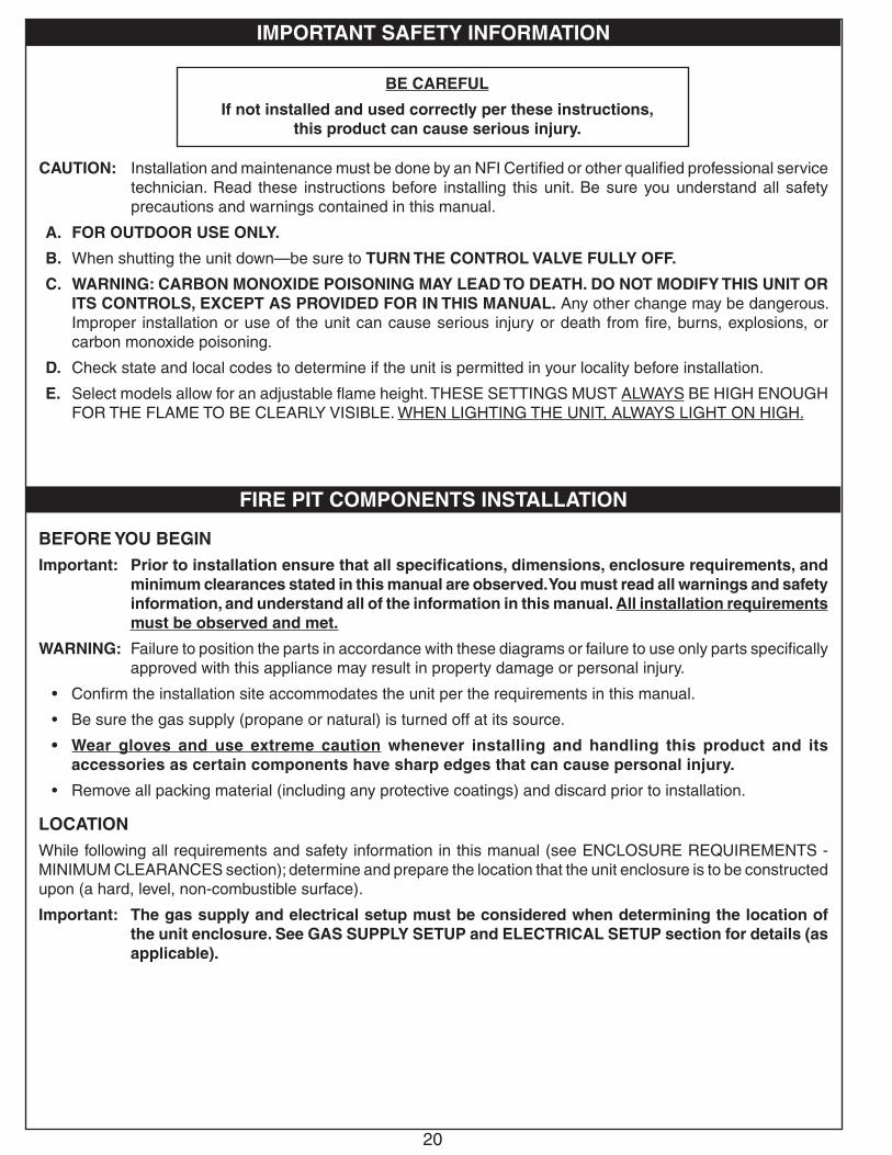
IMPORTANT SAFETY INFORMATION
BE CAREFUL
If not installed and used correctly per these instructions, this product can cause serious injury.
CAUTION: Installation and maintenance must be done by an NFI Certifi ed or other qualifi ed professional service technician. Read these instructions before installing this unit. Be sure you understand all safety precautions and warnings contained in this manual.
A. FOR OUTDOOR USE ONLY.
B. When shutting the unit down—be sure to TURN THE CONTROL VALVE FULLY OFF.
C. WARNING: CARBON MONOXIDE POISONING MAY LEAD TO DEATH. DO NOT MODIFY THIS UNIT OR ITS CONTROLS, EXCEPT AS PROVIDED FOR IN THIS MANUAL. Any other change may be dangerous. Improper installation or use of the unit can cause serious injury or death from fi re, burns, explosions, or carbon monoxide poisoning.
D. Check state and local codes to determine if the unit is permitted in your locality before installation.
E. Select models allow for an adjustable fl ame height. THESE SETTINGS MUST ALWAYS BE HIGH ENOUGH FOR THE FLAME TO BE CLEARLY VISIBLE. WHEN LIGHTING THE UNIT, ALWAYS LIGHT ON HIGH.
FIRE PIT COMPONENTS INSTALLATION
BEFORE YOU BEGINImportant: Prior to installation ensure that all specifi cations, dimensions, enclosure requirements, and
minimum clearances stated in this manual are observed. You must read all warnings and safety information, and understand all of the information in this manual. All installation requirements must be observed and met.
WARNING: Failure to position the parts in accordance with these diagrams or failure to use only parts specifi cally approved with this appliance may result in property damage or personal injury.
• Confi rm the installation site accommodates the unit per the requirements in this manual.
• Be sure the gas supply (propane or natural) is turned off at its source.
• Wear gloves and use extreme caution whenever installing and handling this product and its accessories as certain components have sharp edges that can cause personal injury.
• Remove all packing material (including any protective coatings) and discard prior to installation.
LOCATION While following all requirements and safety information in this manual (see ENCLOSURE REQUIREMENTS - MINIMUM CLEARANCES section); determine and prepare the location that the unit enclosure is to be constructed upon (a hard, level, non-combustible surface).
Important: The gas supply and electrical setup must be considered when determining the location of the unit enclosure. See GAS SUPPLY SETUP and ELECTRICAL SETUP section for details (as applicable).

21
FIRE PIT COMPONENTS INSTALLATION (cont.)
GAS SUPPLY SETUPImportant: Do not connect this unit to a portable L.P.
cylinder. It must be connected to a fi xed piping system.
For Natural or Household Propane Gas Supply:The gas supply is to be brought up from beneath the unit enclosure near its center. Your individual installation may vary. Observe the National Fuel Gas Code and all local codes.
1. Route the gas supply into the area that the unit will rest over (see Fig. 21-1, A).
Note: The gas supply or another fl ex can also be routed through the side of the unit enclosure (through a ventilation opening at the fl oor).
Important: Locate the gas supply line out of pathways where people may trip over it or in areas where the line may be subject to accidental damage (if applicable).
Note: A shut-off valve (not included) in the gas line is required. It must be installed within 6 feet of unit. If it is located within the enclosure, it must be easily accessible. Use a pipe joint compound resistant to all gasses on all NPT fi ttings except fl are fi ttings.
ELECTRICAL SETUP (if applicable)A 120VAC (15 AMP minimum) GFCI GROUNDED 3-wire receptacle (not included) is required within the vicinity of the enclosure to provide power to the unit. The GFCI receptacle must be a WEATHER-PROOF IN-USE COVERED RECEPTACLE. The unit's power supply cord is located on the rear of the control box. Your individual installation may vary. Observe the National Electric Code and all local codes.
1. Wire the receptacle into the area that the enclosure will rest over (see Fig 21-1, B).
• Verify proper polarity of the receptacle.
• If an extension cord is used, ensure it is a 3-wire GROUNDED cord that is rated for the power of the equipment, and is approved for outdoor use with a W-A marking. DO NOT use 2-prong adapters.
• DO NOT TAMPER WITH THE EXTENSION CORD OR THE UNIT POWER-SUPPLY CORD.
Fig. 21-2 Electrical setup detail
3-wire GROUNDED cord from unit
(reference only, cord will be connected at later time)
120VAC (15 AMP minimum) GFCI GROUNDED 3-wire receptacle
Fig. 21-1 Route gas and electrical (receptacle)
120VAC (15 AMP minimum) GFCI
GROUNDED 3-wire receptacle
(if applicable)
B
(Front view of location enclosure
will rest)
AGas
Supply
Installation continued on next page

22
FIRE PIT INSTALLATION (cont.)
CONSTRUCT ENCLOSUREConstruct the enclosure according to your individual install preference, while following the guidelines found in the ENCLOSURE REQUIREMENTS section.
• Construct the enclosure in an appropriate location (refer back to the LOCATION section if needed).
• Follow all information regarding enclosure parameters, ventilation, drainage, and clearance to combustibles listed in the ENCLOSURE REQUIREMENTS section. Failure to do so will prevent the burner system from operating properly and can cause property damage or personal injury.
• Refer to the SPECIFICATIONS AND DIMENSIONS section for cutout details.
Fig. 22-1 Enclosure construction overview (side view)
Ventopenings (4)
Drain openings (2)
(not to scale)
Side wall
Drain holes (min. 4)
Center holein sub-plate for
burner
Gas supply
120VAC(15 AMP min.)
GFCI GROUNDED 3-wire receptacle
(if applicable)
Cutout for control box
(or valve and bracket)
INSTALL BURNER SYSTEMInstall the burner system into the enclosure. This requires:
(A) control box (or valve and bracket) assembly installed into side wall, (B) fl ex connector connected to gas supply, (C) power cord connected to receptacle (06 models only), and (D) burner assembly mounted onto sub-plate.
Refer to the following sections for details on each area of installation.
Fig. 22-2 Install burner system
B
AC
D
(if applicable)
Sub-plate(may need to be secured at a later time to allow for access to interior of enclosure during installation)

23
FIRE PIT INSTALLATION (cont.)
Control Box Assembly (if applicable)Install the control box assembly into the cutout in the enclosure side wall. Use appropriate hardware for the enclosure material/construction and the 4 mounting holes found on the box assembly (see Fig. 23-1).
Valve and Bracket Assembly (if applicable) OCBM-34Install the valve and bracket assembly into the small circular cutout in the enclosure side wall. Use appropriate hardware for the enclosure material/construction and the 2 mounting holes found on the bracket (see Fig. 23-2).
OCB-34Install the valve and bracket assembly into the small circular cutout in the enclosure side wall. Use appropriate hardware for the enclosure material/construction and the 2 mounting holes found on the bracket (see Fig. 23-3).
Fig. 23-1 Install control box (if applicable)
Installation continued on next page
Fig. 23-2 Install valve & bracket assy (if applicable)
(Valve)
(enclosureside wall) Bracket
(secure via 2 mounting holes)
(exploded view for clarity)
Control knob
1/2" diameter cutout
1/2" max. thickness
Fig. 23-3 Install valve & bracket assy (if applicable)
(Valve)
(enclosureside wall) Bracket
(secure via 2 mounting holes)
(exploded view for clarity)
Key cap
1" diameter
cutout
1/2" max. thickness
Secure box via4 mounting holes
Use hardware
appropriate for your setup
5 3/8"8 1/2"
Secure box via4 mounting holes
5 3/8"8 1/2"
- OR -All other models
02 Models

24
All Other Models
FIRE PIT INSTALLATION (cont.)
Connect Gas SupplyCAUTION: DO NOT connect this unit to a portable
L.P. Cylinder. It must be connected to a fi xed piping system.
Important: Before installation, be sure the gas supply (propane or natural) is turned off at its source.
1. Locate the fl ex connector that is coming off the control box (or valve assembly).
2. Locate the gas supply that is beneath the unit (previously routed at beginning of installation).
06 Models Only
A shut-off valve is required within 6 feet of the unit. If it is located within the enclosure, it must be easily accessible.
• Connect the regulator (on end of fl ex connector) to the gas supply (NPT) OR shut-off valve (NPT) using a pipe joint compound resistant to all gasses (see Fig. 24-1, A1 or B1). Tighten securely.
The regulator may need to be disconnected from the fl ex connector to make the proper connections. Reconnect the fl ex to the regulator if removed.
All Other Models
A shut-off valve is required within 6 feet of the unit. If it is located within the enclosure, it must be easily accessible.
If shut-off valve is installed in-line:• Install the supplied fl are-to-NPT adapter to the gas
supply (NPT) using a pipe joint compound resistant to all gasses (see Fig. 24-1, A2). Tighten securely.
• Connect the fl ex connector to the adapter (see Fig. 24-1, A2). Tighten securely.
If shut-off valve is connected to end of gas supply stub:• Connect the fl ex connector to the shut-off valve
(fl are)(see Fig. 24-1, B2). Tighten securely.
Installation continued on next page
06Models
Fig. 24-1 Connecting to a gas line
Gas supply (NPT)
Flare-to-NPT Shut-off valve*
(end of gas supply)
NPT-to-NPT Shut-off valve*
(in-line)
Gas supply (NPT)
Flare-to-NPT adapter
Flex connector(coming from control box or
valve assy)
* Shut-off valve: required, not included, must be within 6 feet of unit
A2 B2
-OR-
Flex connector(coming from control box or
valve assy)
Gas supply (NPT)
NPT-to-NPT Shut-off valve*
(end of gas supply)
Flex connector(coming from control box)
-OR-
A1 B1
NPT-to-NPT Shut-off valve*
(in-line)
Gas supply (NPT)
Flex connector(coming from control box)
RegulatorRegulator
* Shut-off valve: required, not included, must be within 6 feet of unit

25
Leak TestTurn on the gas supply and test at all connections for leaks using a soapy water solution. If bubbles appear, a leak is present. Turn off the gas and tighten at all connections. Repeat until no leaks are present. If a leak persists, turn off the gas supply and contact the local gas company or dealer. NEVER USE A FLAME TO CHECK FOR LEAKS.
Connect Power Supply Cord (if applicable)Route the power supply cord (coming from control box) to the previously wired 120VAC (15 AMP minimum) GFCI GROUNDED 3-wire receptacle and connect (see Fig. 25-1).
Install Batteries (if applicable)At this stage the burner system batteries are to be installed. Reference the SERVICING AND CLEANING - BATTERY INSTALLATION/REPLACEMENT section for details.
Mount Burner AssemblyMount the burner pan onto the non-combustible sub-plate of the enclosure. Use appropriate hardware for the sub-plate material/construction and the 4 mounting holes found on the burner pan (see Fig. 25-2).
Lighting TestPrior to proceeding with installation, perform a lighting test (see lighting instructions for lighting your burner). Allow the unit to completely cool after testing.
Fig. 25-1 Route and connect power supply cord
Connect
ReceptacleMUST be:
120VAC (15 AMP minimum) GFCI
GROUNDED 3-wire
FIRE PIT INSTALLATION (cont.)
Fig. 25-2 Mount burner assembly
Mounting holes (4)

26
DECORATIVE MEDIA PLACEMENT
WARNING: Failure to position the parts in accordance with these diagrams or failure to use only parts specifi cally approved with this appliance may result in property damage or personal injury.
CAUTION: Be sure the unit and the decorative media are completely cool anytime the media is handled. Wear gloves whenever installing and handling as certain media may have sharp edges that can cause personal injury.
Important: If applicable, keep the pilot/igniter screen clear of decorative media and any other items / debris at all times. This will allow for proper ignition and operation. DO NOT cover.
REQUIRED BASE MEDIA (SUPPLIED)
For Lava or Log Setups:The lava granules and coals (included with burner) MUSTfi rst be placed to cover the burner. (The granules are smaller in size; the coals are larger).
1. Pour the 10 lb bag(s) of lava granules into the burner pan, evenly covering the burner pan assembly (with the exception of the screen - if applicable). See Fig. 26-1 and Fig. 26-2.
2. Repeat for the 6 lb bag of lava coals.
For Glass Setups:The lava granules (included with burner) MUST fi rst be placed to cover the burner. (The granules are smaller in size.)
Important: DO NOT use the 6 lb bag of lava coals when installing this burner system with glass. Set the lava coals aside or discard. Only use the 10 lb bag(s) of lava granules.
1. Pour the 10 lb bag(s) of lava granules into the burner pan, evenly covering the burner pan assembly (with the exception of the screen - if applicable). See Fig. 26-1 and Fig. 26-2.
Fig. 26-1 Place lava
Fig. 26-2 Screen detail (if applicable)
DO NOT PLACE ANY MEDIA ON SCREEN
(if applicable)
KEEP CLEAR AT ALL TIMES
(if applicable)
(Piezo model shown)

27
DECORATIVE MEDIA PLACEMENT (cont.)
PRIMARY AND SECONDARY MEDIA OPTIONSAdditional American Fyre Designs decorative media may be placed around the burner if desired. The decorative media is purchased and packaged separately. Contact your local American Fyre Designs dealer for ordering information. Locate the following section(s) that apply to your option(s) chosen and install accordingly.
The supplied media is required for safe operation and proper performance. Place fi rst. All other media is optional.
Reference the SPECIFICATIONS AND DIMENSIONS section for details on the recommended amounts of media.
Lava MediaPour the lava granules or lava coals evenly into the burner area around the perimeter of the already covered burner assembly(see Fig. 27-1).
Important: DO NOT place any additional lava media above the burner. Ensure no existing media is covering the screen (if applicable). Store any excess media in a safe location.
Note: When using both lava granules and coals, granules are to be placed fi rst.
Volcanic StonesAfter the required base media (and any additional lava media) has been placed, pour the volcanic stones evenly into the burner area (see Fig. 27-2). The stones may form a mound. Store any excess media in a safe location.
Log SetsAfter the required base media (and any additional lava media) has been placed, follow the instructions included with your log set chosen for step by step log placement.
Fig. 27-1 Lava media option
Fig. 27-2 Volcanic stones option
Fig. 27-3 Log set option - PRO-27
Fig. 27-4 Log set option - OCL-34
Fig. 27-5 Log set option - OCBW-34
DO NOT DIRECTLY COVER SCREEN
(if applicable)
DO NOT DIRECTLY COVER SCREEN
(if applicable)
DO NOT DIRECTLY COVER SCREEN
(if applicable)
DO NOT DIRECTLY COVER SCREEN
(if applicable)
Place additional lava around perimeter only
KEEP CLEAR AT ALL TIMES
(if applicable)(Piezo model shown)

28
DO NOT PLACE ANY MEDIA ON SCREEN
(if applicable)
DECORATIVE MEDIA PLACEMENT (cont.)
Fig. 28-1 Glass option
Fig. 28-2 Secondary options
Glass shown
River stones shown
Glass MediaAfter the required base lava granules (and any additional granules) have been placed, pour the glass media (glass, gems) evenly into the entire burner area (see Fig. 28-1). The glass should be 2" above the burner.
Important: ONLY lava granules are to be placed above the burner as a base. DO NOT place coals.
DO NOT place any glass media on the screen (if applicable). Ensure no existing lava granules are covering the screen.
DO NOT exceed a height of 2" above the burner when placing glass media. Store any excess media in a safe location.
Additional Secondary OptionsAfter the required base lava media (and any additional lava or glass media) has been placed, various river stone, creekstone, geo shape, wood chunk, and glass nugget options are available. If one of these secondary options are purchased, place them as desired in a decorative pattern on top of the primary media. See Fig. 28-2 for an example.
Note: These options are not designed to be placed directly on the burner.
DO NOT DIRECTLY COVER SCREEN
(if applicable)
(Piezo model shown)

29
1. STOP! Read the safety information above.
2. Ensure the gas control knob is in the OFF position before beginning lighting sequence.
3. Lay a lighted match on the surface of the decorative media near the burner (do not hold the match in your hand) (Fig. 29-1).
4. Once the match is burning and in position, depress the gas control knob and turn it counter-clockwise to the ON position (see Fig. 29-2). Your burner should light.
WARNING: If the burner does not light within five (5) seconds of turning the control knob, immediately depress the control knob and turn clockwise to the OFF position.
Wait approximately five (5) minutes to clear out any gas, and repeat steps 3-4 above.
If your burner fails to light again, depress the control knob and turn clockwise to the OFF position and contact your dealer or gas supplier.Note: The flame height can be adjusted via the control
knob.
TO SHUT OFF GAS TO THE APPLIANCETo extinguish your gas burner, depress the gas control knob and turn it clockwise to the OFF position (see Fig. 29-2). Be sure the control knob is turned fully off to avoid any gas leakage.
WARNING: IF YOU DO NOT FOLLOW THESE INSTRUCTIONS EXACTLY, A FIRE OR EXPLOSION MAY RESULT, CAUSING PROPERTY DAMAGE, PERSONAL INJURY, OR LOSS OF LIFE.
A. BEFORE LIGHTING, smell all around the unit area for gas. Be sure to smell next to the floor, because some gas is heavier than air and will settle on the floor.
B. WHAT TO DO IF YOU SMELL GAS
1. Shut off the gas to the appliance.
2. Extinguish any open flame.
3. If odor continues, immediately call your gas supplier or the fire department.
C. Use only your hand to push in or turn the gas control knob. Never use tools. If the knob will not push in or turn by hand, DO NOT try to repair it. Call a qualified professional service technician. Force or attempted repair may result in fire or explosion.
FOR YOUR SAFETY, READ BEFORE LIGHTING
Fig. 29-1
Fig. 29-2
OFFO
NApply match - then turn on gas
LIGHTING INSTRUCTIONS - MATCH LIT VALVE MODELS
USE, CARE, & SERVICE

30
1. ARRÊT! Lire les consignes de sécurité ci-dessus.2. S'assurer que le bouton de contrôle du gaz est en position
OFF (éteindre) avant de séquence d'éclairage à partir la position.
3. Poser une allumette allumée sur la surface du support décoratif près du brûleur (ne pas tenir l'allumette dans la main) (Fig. 30-1).
4. Une fois que le match est en feu et en position, appuyer sur le bouton de contrôle du gaz et tournez dans le sens antihoraire à la position de ON (allumer) (voir Fig. 30-2). Votre brûleur devrait s'allumer.
AVERTISSEMENT: Si le brûleur ne se allume pas la lumière dans les cinq (5) secondes de tourner le bouton de commande, appuyez immédiatement sur le bouton de commande et tournez dans le sens horaire à la position OFF (éteindre).Attendez environ cinq (5) minutes pour laisser échapper tout le gaz, et répétez les étapes 3-4 ci-dessus.
Si votre brûleur ne s'allume pas, appuyer sur le bouton de commande et tournez dans le sens horaire à la position OFF (éteindre) et contactez votre revendeur ou fournisseur de gaz.Note: La hauteur des flammes peut être réglée via le bouton
de commande.POUR ARRÊTER LE GAZ À L'APPAREILPour éteindre le brûleur à gaz, appuyer sur le bouton de contrôle du gaz et tourner dans le sens horaire à la position OFF (éteindre) (voir Fig. 30-2). Assurez-vous que le bouton de commande est tourné complètement hors tension pour éviter toute fuite de gaz.
AVERTISSEMENT: SI VOUS NE SUIVEZ PAS CES INSTRUCTIONS À LA LETTRE, UN INCENDIE OU UNE EXPLOSION POURRAIENT S'ENSUIVRE, CAUSANT DES DOMMAGES MATÉRIELS, DES BLESSURES OU DES PERTES DE VIE.
A. AVANT D'ALLUMER, sentez tout autour de l'unité de surface pour le gaz. Assurez-vous de sentir près du plancher, car certains gaz sont plus lourds que l'air et se déposent sur le sol.
B. QUE FAIRE SI UNE ODEUR DE GAZ
1. Coupez le gaz à l'appareil.
2. Éteindre toute flamme nue.
3. Si l'odeur persiste, appelez immédiatement votre fournisseur de gaz ou le service des incendies.
C. N'utilisez que votre main pour enfoncer ou tourner le bouton de contrôle du gaz. Ne jamais utiliser d'outils. Si le bouton ne sera pas enfoncer ou à tourner à la main, NE PAS essayer de le réparer. Appelez un technicien de service qualifié. Force ou une tentative de réparation pourrait provoquer un incendie ou une explosion.
POUR VOTRE SÉCURITÉ, LIRE AVANT D'ALLUMER
OFFO
N
ÉTEINDREALLUMER
Fig. 30-2
Appliquer match - puis tourner sur le gaz
Fig. 30-1
INSTRUCTIONS D'ALLUMAGE - MODÈLE MANUEL VANNE D'ÉCLAIRAGE

31
1. STOP! Read the safety information above.
2. Ensure the key valve is completely in the OFF position before beginning lighting sequence.
3. Lay a lighted match on the surface of the decorative media near the burner (do not hold the match in your hand) (Fig. 31-1).
4. Once the match is burning and in position, turn the key valve counter-clockwise a 1/4 turn to the ON position (see Fig. 31-2). Your burner should light.
WARNING: If the burner does not light within (5) seconds of turning on the key valve, immediately turn the key valve clockwise a 1/4 turn to the OFF position.
Wait approximately five (5) minutes to clear out any gas, and repeat steps 3-4 above.
If your burner fails to light again, turn the key valve clockwise a 1/4 turn to the OFF position and contact your dealer or gas supplier.
Note: The flame height can be adjusted via the key valve.
TO SHUT OFF GAS TO THE APPLIANCETo extinguish your gas burner, turn the key valve clockwise a 1/4 turn to the OFF position (see Fig. 31-2). Be sure the key valve is turned fully off to avoid any gas leakage.
WARNING: IF YOU DO NOT FOLLOW THESE INSTRUCTIONS EXACTLY, A FIRE OR EXPLOSION MAY RESULT, CAUSING PROPERTY DAMAGE, PERSONAL INJURY, OR LOSS OF LIFE.
A. BEFORE LIGHTING, smell all around the unit area for gas. Be sure to smell next to the floor, because some gas is heavier than air and will settle on the floor.
B. WHAT TO DO IF YOU SMELL GAS
1. Shut off the gas to the appliance.
2. Extinguish any open flame.
3. If odor continues, immediately call your gas supplier or the fire department.
C. Use only a proper key to turn the gas line valve. Never use tools. If the valve will not turn, DO NOT try to repair it. Call a qualified professional service technician. Force or attempted repair may result in fire or explosion.
FOR YOUR SAFETY, READ BEFORE LIGHTING
Fig. 31-1
LIGHTING INSTRUCTIONS - MATCH LIT KEY MODELS
Key valve
Fig. 31-2
OFFON OFFON
OFF /REMOTE ON
LEARN
REMOTE ONOFF
Turn valvecounter-clockwise
1/4 turn to ON
Turn valveclockwise
1/4 turn to OFF
32
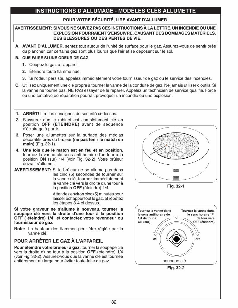
1. ARRÊT! Lire les consignes de sécurité ci-dessus.
2. S'assurer que le robinet est complètement clé en position OFF (ÉTEINDRE) avant de séquence d'éclairage à partir.
3. Poser une allumettes sur la surface des médias décoratifs près du brûleur (ne pas tenir le match en main) (Fig. 32-1).
4. Une fois que le match est en feu et en position, tournez la vanne clé sens anti-horaire d'un tour à la position ON (sur) 1/4 (voir Fig. 32-2). Votre brûleur devrait s'allumer.
AVERTISSEMENT: Si le brûleur ne se allume pas dans les cinq (5) secondes de tourner sur la vanne clé, tournez immédiatement la vanne clé vers la droite d'une tour à la position OFF (éteindre) 1/4.
Attendez environ cinq (5) minutes pour laisser échapper tout le gaz, et répétez les étapes 3-4 ci-dessus.
Si votre graveur ne s'allume à nouveau, tourner la soupape clé vers la droite d'une tour à la position OFF ( éteindre) 1/4 et contactez votre revendeur ou fournisseur de gaz.Note: La hauteur des flammes peut être réglée par la
vanne clé.
POUR ARRÊTER LE GAZ À L'APPAREILPour éteindre votre brûleur à gaz, tourner la soupape clé vers la droite d'une tour à la position OFF (éteindre) 1/4 (voir Fig. 32-2). Assurez-vous que la vanne clé est tournée entièrement au large pour éviter toute fuite de gaz.
AVERTISSEMENT: SI VOUS NE SUIVEZ PAS CES INSTRUCTIONS À LA LETTRE, UN INCENDIE OU UNE EXPLOSION POURRAIENT S'ENSUIVRE, CAUSANT DES DOMMAGES MATÉRIELS, DES BLESSURES OU DES PERTES DE VIE.
A. AVANT D'ALLUMER, sentez tout autour de l'unité de surface pour le gaz. Assurez-vous de sentir près du plancher, car certains gaz sont plus lourds que l'air et se déposent sur le sol.
B. QUE FAIRE SI UNE ODEUR DE GAZ
1. Coupez le gaz à l'appareil.
2. Éteindre toute flamme nue.
3. Si l'odeur persiste, appelez immédiatement votre fournisseur de gaz ou le service des incendies.
C. Utilisez uniquement une clé propre à tourner la vanne de la conduite de gaz. Ne jamais utiliser d'outils. Si la vanne ne tourne pas, NE PAS essayer de le réparer. Appelez un technicien de service qualifié. Force ou une tentative de réparation pourrait provoquer un incendie ou une explosion.
POUR VOTRE SÉCURITÉ, LIRE AVANT D'ALLUMER
Fig. 32-1
INSTRUCTIONS D'ALLUMAGE - MODÈLES CLÉS ALLUMETTE
soupape clé
Fig. 32-2
OFFON OFFON
OFF /REMOTE ON
LEARN
REMOTE ONOFF
Tournez la vanne dansle sens antihoraire de1/4 de tour àON (sur)
Tournez la vanne dans le sens horaire 1/4
de tour versOFF (éteindre)

33
1. STOP! Read the safety information above.
2. Ensure the gas control knob is in the OFF position before beginning lighting sequence.
3. Press and hold the electronic igniter button (see Fig. 33-1). The igniter will begin to spark with a rapid clicking sound.
4. While holding the igniter button in, verify that the electrode is sparking. Then turn the gas control knob counter-clockwise to the ON position, depress, and hold for 15 seconds (see Fig. 33-2). Your burner should light within 5 seconds.
Holding the knob in for 15 seconds allows the safety valve to activate and the burner to remain lit.
WARNING: If the burner fails to light within 5 seconds, immediately depress the control knob and turn clockwise to the OFF position.
Wait approximately five (5) minutes to clear out any gas, and repeat steps 3-4 above.
If your burner fails to light again, depress the control knob and turn clockwise to the OFF position and contact your dealer or gas supplier.
Note: The flame height can be adjusted via the control knob.
TO SHUT OFF GAS TO THE APPLIANCETo extinguish your gas burner, depress the gas control knob and turn it clockwise to the OFF position (see Fig. 33-2). Be sure the control knob is turned fully off to avoid any gas leakage.
WARNING: IF YOU DO NOT FOLLOW THESE INSTRUCTIONS EXACTLY, A FIRE OR EXPLOSION MAY RESULT, CAUSING PROPERTY DAMAGE, PERSONAL INJURY, OR LOSS OF LIFE.
A. BEFORE LIGHTING, smell all around the unit area for gas. Be sure to smell next to the floor, because some gas is heavier than air and will settle on the floor.
B. WHAT TO DO IF YOU SMELL GAS
1. Shut off the gas to the appliance.
2. Extinguish any open flame.
3. If odor continues, immediately call your gas supplier or the fire department.
C. Use only your hand to push in or turn the gas control knob. Never use tools. If the knob will not push in or turn by hand, DO NOT try to repair it. Call a qualified professional service technician. Force or attempted repair may result in fire or explosion.
FOR YOUR SAFETY, READ BEFORE LIGHTING
LIGHTING INSTRUCTIONS - PIEZO MODELS
Fig. 33-1
Fig. 33-2
Igniter button
OFFO
N
Valve knob

34
1. ARRÊT! Lire les consignes de sécurité ci-dessus.
2. S'assurer que le bouton de contrôle du gaz est en position OFF (éteindre) avant de séquence d'éclairage à partir la position.
3. Appuyez et maintenez enfoncé le bouton d'allumage électronique (voir Fig. 34-1). L'allumeur commence à susciter un déclic rapide.
4. Tout en maintenant le bouton d'allumage dans, vérifiez que l'électrode est étincelles. Ensuite, tournez la commande de gaz dans le sens anti-horaire à la position ON (allumer), appuyer et maintenir pendant 15 secondes (voir Fig. 34-2). Votre brûleur doit allumer.
Maintenir le bouton pendant 15 secondes permet à la soupape de sécurité et pour activer le brûleur reste allumé
AVERTISSEMENT: Si le brûleur ne s'allume pas dans les 5 secondes, appuyez immédiatement sur le bouton de commande et tournez dans le sens horaire à la position OFF (éteindre).
Attendez environ cinq (5) minutes pour laisser échapper tout le gaz, et répétez les étapes 3-4 ci-dessus.
Si votre brûleur ne s'allume pas, appuyer sur le bouton de commande et tournez dans le sens horaire à la position OFF (éteindre) et contactez votre revendeur ou fournisseur de gaz.
Note: La hauteur de flamme est réglable via le bouton de commande.
POUR ARRÊTER LE GAZ À L'APPAREILPour éteindre le brûleur à gaz, appuyer sur le bouton de contrôle du gaz et tourner dans le sens horaire à la position OFF (éteindre) (voir Fig. 34-2). Assurez-vous que le bouton de commande est tourné complètement hors tension pour éviter toute fuite de gaz.
AVERTISSEMENT: SI VOUS NE SUIVEZ PAS CES INSTRUCTIONS À LA LETTRE, UN INCENDIE OU UNE EXPLOSION POURRAIENT S'ENSUIVRE, CAUSANT DES DOMMAGES MATÉRIELS, DES BLESSURES OU DES PERTES DE VIE.
A. AVANT D'ALLUMER, sentez tout autour de l'unité de surface pour le gaz. Assurez-vous de sentir près du plancher, car certains gaz sont plus lourds que l'air et se déposent sur le sol.
B. QUE FAIRE SI UNE ODEUR DE GAZ
1. Coupez le gaz à l'appareil.
2. Éteindre toute flamme nue.
3. Si l'odeur persiste, appelez immédiatement votre fournisseur de gaz ou le service des incendies.
C. N'utilisez que votre main pour enfoncer ou tourner le bouton de contrôle du gaz. Ne jamais utiliser d'outils. Si le bouton ne sera pas enfoncer ou à tourner à la main, NE PAS essayer de le réparer. Appelez un technicien de service qualifié. Force ou une tentative de réparation pourrait provoquer un incendie ou une explosion.
POUR VOTRE SÉCURITÉ, LIRE AVANT D'ALLUMER
INSTRUCTIONS D'ALLUMAGE - MODÈLES PIEZO
Fig. 34-1
Bouton d'allumage
OFFO
N
ÉTEINDREALLUMER
Fig. 34-2
Bouton de la valve

35
FOR YOUR SAFETY, READ BEFORE LIGHTING
WARNING: If you do not follow these instructions exactly, a fi re or explosion may result causing property damage, personal injury or loss of life.
A. This appliance is equipped with an ignition device that automatically lights the pilot. DO NOT attempt to light the pilot by hand.
B. BEFORE LIGHTING, smell all around the unit area for gas. Be sure to smell next to the fl oor, because some gas is heavier than air and will settle on the fl oor.
C. WHAT TO DO IF YOU SMELL GAS
1. Shut off the gas to the appliance.
2. Extinguish any open fl ame.
3. If odor continues, immediately call your gas supplier or the fi re department.
D. Use only your hand to push in or move the controls. Never use tools. If the control will not push in or move by hand, DO NOT try to repair it. Call a qualifi ed professional service technician. Force or attempted repair may result in fi re or explosion.
OFF
ON
Fig. 35-2 Remote transmitter detail
ON button
OFF button
Signal light
REMOTE LIGHTINGCAUTION: DO NOT attempt to light the pilot by hand.
Note: If the remote does not function, and batteries with an adequate power level are installed, refer to the SYNCING THE REMOTE section.
Note: Steps 1-2 may not be required if previously done during an earlier lighting.
1. Ensure the manual ON/OFF switch is in the OFF/REMOTE position (see Fig. 35-1).
2. Locate the 3-position switch on the remote receiver (see Fig. 35-1), and slide the switch to the REMOTE position.
3. Locate the remote transmitter and press the ON button (see Fig. 35-2). The ignition sequence will begin.
The remote receiver will emit an audible "beep"; then the igniter will begin to spark. After the pilot lights and is established, the valve will automatically open and the burner will light.
Note: The ignition sequence will take approximately 5 seconds.
WARNING: If the pilot fails to light within 5 seconds, or if the burner fails to light within 5 seconds of pilot lighting, press the OFF button on the remote transmitter and/or slide the switch to the OFF position. Allow fi ve (5) minutes for any gas in the unit to dissipate, then repeat steps 1-3 above. IF YOU SMELL GAS, SEE STEP B ABOVE.
If the pilot fails to light after several tries, turn all control/remote system components to OFF and refer to the TROUBLESHOOTING section for further details.
OFF / REMOTEON
LEAR
N
REMOTE
ON
OFF
Remote receiver(in REMOTE position)
Fig. 35-1 Control panel detail
LIGHTING INSTRUCTIONS - 02 / 06 REMOTE MODELS
(06 Model shown)
Manual ON/OFF switch(in OFF/REMOTE position)

36
POUR VOTRE SÉCURITÉ, LISEZ AVANT D'ALLUMER
AVERTISSEMENT: Si vous ne suivez pas ces instructions à la lettre, un incendie ou une explosion entraînant des dommages matériels, des blessures ou des pertes de vie.
A. Cet appareil est équipé d'un dispositif d'allumage qui allume automatiquement la veilleuse. NE PAS essayer d'allumer la veilleuse à la main.
B. AVANT L'ALLUMAGE, sentez autour de l'unité de surface pour le gaz. Soyez sûr de sentir près du plancher, car certains gaz sont plus lourds que l'air et se déposent sur le sol.
C. QUE FAIRE SI UNE ODEUR DE GAZ
1. Couper le gaz de l'appareil.
2. Éteindre toute fl amme nue.
3. Si l'odeur persiste, appelez immédiatement votre fournisseur de gaz ou le service d'incendie.
D. Utilisez seulement votre main pour pousser ou déplacer les commandes. Ne jamais utiliser des outils. Si la commande ne sera pas à enfoncer ou à déplacer à la main, NE PAS essayer de le réparer. Appelez un technicien de service professionnel qualifi é. La force ou la tentative de réparation pourrait provoquer un incendie ou une explosion.
OFF
ON
Fig. 36-2 Détail télécommande
ON(sur)
touche
OFF (éteindre)
touche
feux de signalisation
DISTANCE DE L'ÉCLAIRAGEATTENTION: NE PAS essayer d'allumer la veilleuse
manuellement.
Note: Si la télécommande ne fonctionne pas, et des batteries avec un niveau de puissance adéquate sont installés, se référer à la section synchronisation des REMOTE.
Note: Les étapes 1 et 2 ne peuvent être tenus si elle a déjà fait au cours d'un éclairage plus tôt.
1. Vérifi ez que l'interrupteur manual est en position OFF/REMOTE (éteindre/éloigné) (voir Fig. 36-1).
2. Repérez l'interrupteur à 3 positions sur le récepteur de télécommande (voir Fig. 36-1), Et faites glisser l'interrupteur à la position REMOTE(éloigné).
3. Localisez la télécommande et appuyez sur la touche ON (sur) (voir Fig. 36-2). La séquence d'allumage commence.
Le récepteur à distance émettra un "bip" audible; alors l'allumeur commencera à s'allumer. Après les feux de pilotes et est établie, la vanne se ouvre automatiquement et le brûleur se allume.
Note: La séquence d'allumage prendra environ 5 secondes.
AVERTISSEMENT: Si la veilleuse ne s'allume pas dans les 5 secondes ou si le brûleur ne s'allume pas dans les 5 secondes suivant l'allumage de la veilleuse, appuyez sur le bouton OFF de la télécommande et / ou faites glisser le commutateur en position OFF. Autoriser cinq (5) minutes pour tout gaz dans l'unité à se dissiper, puis répétez les étapes 1 et 2 ci-dessus. SI VOUS UNE ODEUR DE GAZ, voir l'étape B ci-dessus.
Si le pilote ne parvient pas à allumer après plusieurs essais, tournez tout contrôle / composants du système à distance sur OFF et se référer à la section dépannage pour plus de détails.
Fig. 36-1 Contrôle détail du panneau
OFF / REMOTEON
LEAR
N
REMOTE
ON
OFF
Récepteur à distance(en position REMOTE)
INSTRUCTIONS D'ALLUMAGE - 02 / 06 DISTANCE MODÈLES
(06 Modèle illustré)
Interrupteur manual sur/éteindre(en la position OFF/REMOTE)

37
MANUAL LIGHTINGCAUTION: DO NOT attempt to light the pilot by hand.
1. Ensure the manual ON/OFF switch is in the OFF/REMOTE position (see Fig. 37-1).
2. Locate the 3-position switch on the remote receiver (see Fig. 37-1), and slide the switch to the ON position.
The igniter will begin to spark. After the pilot lights and is established, the valve will automatically open and the burner will light.
Note: The ignition sequence will take approximately 5 seconds.
WARNING: If the pilot fails to light within 5 seconds, or the burner fails to light within 5 seconds of pilot lighting, slide the switch to the OFF position. Allow fi ve (5) minutes for any gas in the unit to dissipate, then repeat steps 1-2 above. IF YOU SMELL GAS, SEE STEP B AT BEGINNING OF LIGHTING INSTRUCTIONS.
If the pilot fails to light after several tries, turn the system OFF and contact a qualifi ed professional service technician.
Note: In manual mode, the remote transmitter will not operate the burner system.
SHUTTING DOWNFor remote shut down, press the OFF button on the remote transmitter.
For manual shutdown, slide the switch on the remote receiver to the OFF position.
MANUAL ON/OFF SWITCHThe manual ON/OFF switch should remain in the OFF/REMOTE position to allow for remote system operation (see Fig. 37-1).
In the event the remote system batteries are dead (or if the system is not functioning) the switch can be used to turn the burner on and off.
PILOT APPEARANCEPeriodically check the pilot for proper fl ame pattern. The pilot should be a steady fame, encircling the fl ame sensor. It is preset at the factory (see Fig. 37-2).
If the pilot fl ame burns incorrectly: shut down completely and contact a qualifi ed professional service technician.
REMOTE STORAGE AND CAREWhen not in use, store the remote transmitter in a safe location.
Important: Remote is NOT weatherproof. Protect it from the elements at all times and store when not in use.
Fig. 37-1 Control panel detail
OFF / REMOTEON
LEAR
N
REMOTE
ON
OFF
Remote receiver(in ON position)
LIGHTING INSTRUCTIONS - 02 / 06 REMOTE MODELS (cont.)
Fig. 37-2 Proper pilot fl ame
02 Model
06 Model
(06 Model shown)
Flame sensor
Flame sensor
Manual ON/OFF switch(in OFF/REMOTE position)

38
ÉCLAIRAGE MANUELATTENTION: NE PAS essayer d'allumer la veilleuse à
la main.
1. Vérifi ez que l'interrupteur manuel sur/éteindre est en position OFF/REMOTE (éteindre/éloigné) (voir Fig. 38-1).
2. Repérez l'interrupteur à 3 positions sur le récepteur de télécommande (voir Fig. 38-1), Et faites glisser le commutateur en position ON (sur). L'igniteur va commencer à déclencher. Après les feux de pilotes et est établie, la vanne se ouvre automatiquement et le brûleur se allume.
Note: La séquence d'allumage prendra environ 5 secondes.
AVERTISSEMENT: Si la veilleuse ne s'allume pas dans les 5 secondes ou si le brûleur ne s'allume pas dans les 5 secondes suivant l'allumage de la veilleuse, faites glisser le commutateur en position OFF. Autoriser cinq (5) minutes pour tout gaz dans l'unité à se dissiper, puis répétez les étapes 1-2 ci-dessus. SI VOUS UNE ODEUR DE GAZ, voir l'étape B AU DÉBUT DE instructions d'allumage.
Si le pilote ne se allume pas après plusieurs essais, tournez le système OFF (éteindre) et contacter un technicien de service professionnel qualifi é.Note: En mode manuel, la télécommande ne fonctionnera
pas le système du brûleur.ARRÊTPour arrêt à distance, appuyez sur le bouton OFF (éteindre) de la télécommande.Pour un arrêt manuel, faites glisser le commutateur sur le récepteur de la télécommande à la position OFF (éteindre).INTERRUPTEUR MANUEL SUR/ÉTEINDREL'interrupteur manuel sur/éteindre doit rester dans la position OFF/REMOTE (éteindre/éloigné) pour permettre le fonctionnement du système à distance (voir Fig. 38-1).Si les piles du système distant sont épuisées (ou si le système ne fonctionne pas), vous pouvez utiliser le commutateur manuel pour allumer et éteindre le brûleur.ASPECT PILOTEContrôler régulièrement le pilote pour motif de fl amme correcte. La fl amme de la veilleuse doit encercler le détecteur de fl amme, et est préréglé en usine (voir Fig. 38-2).Si la fl amme de la veilleuse ne brûle pas correctement: éteignez complètement et contactez un technicien qualifi é.
STOCKAGE DISTANCE ET SOINSLorsqu'il n'est pas utilisé, rangez l'émetteur distant dans un endroit sûr.Important: À distance ne est pas étanche. Protéger
contre les éléments à tout moment. Magasin lorsque vous ne utilisés.
Fig. 38-1 Contrôle détail du panneau
OFF / REMOTEON
LEAR
N
REMOTE
ON
OFF
Récepteur à distance(en position ON)
INSTRUCTIONS D'ALLUMAGE - 02 / 06 DISTANCE MODÈLES (cont.)
Fig. 38-2 Bonne fl amme pilote
02 Modèle
06 Modèle
(06 Modèle illustré)
Détecteur de fl ammes
Détecteur de fl ammes
Interrupteur manual sur/éteindre(en la position OFF/REMOTE)

39
SERVICING AND CLEANING
Each installation site for any unit presents its own unique combustion environment. Specific factors such as weather, wind currents, yard debris, altitude, drafts, the size of the surrounding area, all have an influence on the proper operation of the unit. A normally operating unit will demonstrate the following characteristics:
• A lively, realistic yellow flame
• Odor-free
If the flame is not clean (identifiable by excessive sooting on the decorative media), refer to the information below. Some soot on the media may occur and should not be a concern unless excessive.
• Cover your unit whenever it is completely cool and not in use (see PROTECTIVE COVER section), and follow the guidelines below at least annually.
ANNUAL CLEAN / INSPECTION GUIDELINESThe unit and the installation must be inspected annually. Refer to these instructions for details. Performing these procedures will ensure proper operation, appearance, and safety. WEAR GLOVES.
If maintenance is required, it must be done by a qualified professional service technician.
• Always shut off the gas to the unit while performing service work.
• Allow the unit to cool before servicing.
• The entire burner system and enclosure should be inspected regularly:
Excessive debris can build up on this unit from leaves, dirt, or other debris. It is critical that all control components, burners, pilot/igniter screen (if applicable), vent openings, drain openings, and the surrounding area be kept clear and free at all times.
Examine that all components are properly assembled / installed as instructed in this manual.
Ensure that all decorative media is properly placed as instructed in this manual.
Ensure that the pilot/igniter screen on the burner pan is clear of decorative media and any other items/debris.
Replace batteries as needed. See BATTERY INSTALLATION/REPLACEMENT section for details.
• The burner assembly must be replaced prior to the unit being put into operation if it is evident that the burner is damaged. Contact your local dealer for replacement parts.
• DO NOT use substitute materials when replacing any components of the appliance.
• Keep the vent openings, drain openings, and surrounding area of the enclosure clear and free at all times.
• Periodically perform visual checks of the burner flames and pilot flames (if applicable). The burner flames should be blue at the base with a combination of blue/yellow at the body and tips. The pilot (if applicable) should be a steady flame, encircling the flame sensor. Contact a qualified professional service technician for maintenance.
• Any guard or other protective device removed for servicing the appliance shall be replaced prior to operating appliance.
• Verify proper operation after servicing.
CAUTION: HOT DURING OPERATION AND AFTER USE. Children must be supervised when in the vicinity of this appliance. Serious injury may occur! Children must be alerted to the hazard of high surface temperatures and should stay away to avoid burns or clothing ignition.
Keep vent openings, drain openings, and surrounding area
clear for proper venting and water drainage
Fig. 39-1 Keep openings & area clear
(your model and design may vary)

40
SERVICING AND CLEANING (cont.)
PROTECTIVE COVERIt is highly recommended to have a waterproof and heavy-duty cover constructed to fi t the custom design of the enclosure. At minimum, the burner assembly should be covered when cool and not in use.
Note: Certain decorative media (such as river stones, logs, etc.) may interfere with the proper placement of the cover. They will need to be removed and stored in a safe location when the cover is in use.
Remove the cover before use.
SYNCING THE REMOTE SYSTEM (if applicable)Ensure the burner system is off and completely cool.
Locate the 3-position switch on the remote receiver and slide it to the REMOTE position. Use the tip of a pen or a wire clip to push the LEARN button and release. See Fig. 40-1. A beep will be heard. Then press and hold the ON button on the remote transmitter; a series of beeps should be heard. The remote system is now synced. Refer to the LIGHTING INSTRUCTIONS to test.
FUSE REPLACEMENT (if applicable)Ensure the burner system is off and completely cool.
1. Remove the 4 screws on the control box that are securing it into the enclosure side wall (see Fig. 40-2, A).
2. Slightly pull the control box forward in the cutout. Using a Phillips screwdriver, remove the 4 screws that are securing the control panel into the box (see Fig. 40-2, B).
3. Carefully pull the control panel away from the box.
4. "Push in and twist" the fuse holder (red wire), exposing the fuse (see Fig. 40-3).
5. Replace the fuse accordingly (3AG 2 AMP).
6. Reassemble the fuse holder, control panel, and control box.
CONTROL BOX INTERIOR ACCESS (if applicable)Ensure the burner system is off and completely cool.
If access to the interior of the control box is required (for servicing), follow the instructions below:
1. Remove the 4 screws on the control box that are securing it into the enclosure side wall (see Fig. 40-2, A).
2. If possible, completely pull the control box out of the cutout. Alternatively it will need to be accessed from within the enclosure.
3. Once the control box is accessible, remove the bottom plate by using a screwdriver to pry open the tabs found along the box. The control panel can also be removed by unfastening the 4 screws that are securing it to the box. See Fig. 40-4.
4. Replace the bottom plate, control panel, and re-install the control box when servicing is done.
LEAR
N
REMOTE
ON
OFF
Fig. 40-1 Remote receiver sync detail
Fig. 40-3 Replace fuse
Carefully open box and replace fuse
(red wire)
Fig. 40-4 Control panel interior access
Control box
Control panel
Bottom plate
(Pry open tabs)
Fig. 40-2 Remove screws to access fuse
B
A

41
SERVICE AND CLEANING (cont.)
BATTERY INSTALLATION/REPLACEMENT (if applicable)CAUTION: Ensure the unit is connected to the gas line
and has been tested for leaks before you insert batteries.
CAUTION: Turn off the burner and allow the unit to completely cool prior to any battery replacements.
Important: Prior to inserting batteries, always apply a small amount of dielectric grease to both ends of each battery. This will ensure conductivity and prevent moisture from affecting the contact.
Important: Low/dead batteries will affect burner system operation. Replace batteries any time the burner will not turn on.
Igniter battery The igniter requires 1 AA battery to operate (included). Locate the igniter on the control panel and unscrew the igniter cap (see Fig. 41-1, A). Remove the existing battery (see Fig. 41-1, B). Insert the new battery (negative end first) into the igniter and replace the cap. Screw the cap down until snug. DO NOT overtighten.
Remote transmitter batteryThe remote transmitter requires 1 12V battery to operate (included). Locate the transmitter, remove the lid (found on rear), and properly insert the new battery as marked. Re-secure the lid. See Fig. 41-2.
Remote receiver batteriesThe remote receiver requires 4 AA batteries to operate (included). Locate the receiver on the control panel, remove the 2 screws, then pull the receiver out of the control panel. Slide open the lid, and properly insert the new batteries as marked. See Fig. 41-3.
Replace the lid, replace the receiver, and secure using the 2 screws.
Burner system batteriesThe burner system requires 2 D batteries to operate (included). Locate the access plate on the control panel, remove the large screw, then pull it out and turn it over. Properly insert the new batteries as marked. See Fig. 41-4.
Replace the access plate and secure using the large screw.
+
_
Fig. 41-1 Replace battery
Fig. 41-3 Remote receiver batteries
02 model shown
Fig. 41-4 Burner system batteries
02 model only
Fig. 41-2 Transmitter battery
Remove lid for 12V
battery access
AA batteries
D batteries (on rear of
access plate)
Install new battery &
replace cap
B
Unscrew cap
A
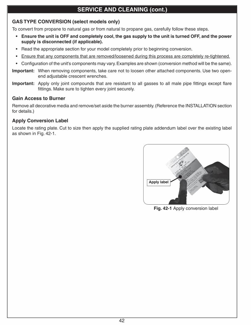
42
SERVICE AND CLEANING (cont.)
GAS TYPE CONVERSION (select models only)To convert from propane to natural gas or from natural to propane gas, carefully follow these steps.
• Ensure the unit is OFF and completely cool, the gas supply to the unit is turned OFF, and the power supply is disconnected (if applicable).
• Read the appropriate section for your model completely prior to beginning conversion.
• Ensure that any components that are removed/loosened during this process are completely re-tightened.
• Configuration of the unit's components may vary. Examples are shown (conversion method will be the same).
Important: When removing components, take care not to loosen other attached components. Use two open-end adjustable crescent wrenches.
Important: Apply only joint compounds that are resistant to all gasses to all male pipe fittings except flare fittings. Make sure to tighten every joint securely.
Gain Access to BurnerRemove all decorative media and remove/set aside the burner assembly. (Reference the INSTALLATION section for details.)
Apply Conversion LabelLocate the rating plate. Cut to size then apply the supplied rating plate addendum label over the existing label as shown in Fig. 42-1.
Fig. 42-1 Apply conversion label
Apply label

43
Piezo Manual ModelNote: Ensure the media and burner are removed.
1. Disconnect the flex connector and adapter from the old gas supply, if applicable (A).
2. Remove the 4 screws on the control box that are securing it into the enclosure side wall (see B).
3. If possible, completely pull the control box out of the cutout. Alternatively it will need to be accessed from within the enclosure.
4. Once the control box is accessible, use an adjustable wrench to remove the 2 flex connectors and nuts from the rear of the control box (see C).
5. Using a Phillips screwdriver, remove the 4 screws that are securing the control panel into the box (see D). Pull the control panel out of the box to expose the regulator. If clearance is required, remove the thermocouple (DO NOT kink) from the safety valve and the igniter wire from the piezo igniter. See E.
6. OCBE-44 Models: Disconnect the flex connector (attached to the burner), the adapter, and the fuel injector / air mixer (in that order, see F1). Then connect the new air mixer / fuel injector, then adapter, then flex connector. See orifice data.
OCBE-34 Models: Remove the flex connector attached to the orifice holder. Then remove the orifice holder. See F2.
Remove the orifice from the holder and replace with the proper size for the new gas type (see F2 and orifice data).
• Nat. Gas Only: Slide the supplied air shutter over the burner pipe (see F2). (The air shutter is not to be used for L.P. gas.)
• Reinstall the orifice holder and reattach the flex connector.
7. Convert the regulator (G):a. Unscrew and remove the cap and the attached
converter (G1).b. Remove the converter by carefully pulling it away
from the center of the cap (G2). Then turn the converter around and replace it carefully. It will snap into place. Check that you can read the gas type (G3).
c. Replace the cap into the regulator (G4).8. If removed, replace the igniter wire and thermocouple.
Then re-install the control panel, followed by the 2 nuts and flex connectors onto the rear of the control box.
9. Connect to new gas supply for your setup (H). Refer to CONNECT GAS SUPPLY section.
10. LEAK TEST: Turn on the gas supply and test at all connections for leaks using a soapy water solution (see INSTALLATION section if needed).
11. Re-install the control box assembly into the cutout in the enclosure side wall.
12. LIGHTING TEST: Re-install burner pan, then perform a lighting test (see LIGHTING INSTRUCTIONS section).
13. Replace the decorative media.
SERVICE AND CLEANING (cont.)
G1
G2G4
G3Read gas type here
Fig. 43-1
Orifices:OCBE-34: Nat: #23 / L.P: #40OCBE-44: Nat: AB-2-E / L.P: AM-2-29
B
CD
E
E
F1
F2
Flex
Orifice Holder
Orifice
Air shutter
(Nat. only)
Burner pipe
G
A/H
Fuel injector / air mixer
Adapter
Flex connector

44
SERVICE AND CLEANING (cont.)
06 Remote ModelNote: Ensure the media and burner are removed, and the power supply is disconnected.
1. Disconnect the flex connector and regulator from the old gas supply, if applicable (A).2. OCBE-44 Models: Disconnect the flex connector (attached to the burner), the adapter, and the fuel injector / air mixer
(in that order, see B1). Then connect the new air mixer / fuel injector, then adapter, then flex connector. See orifice data.OCBE-34 Models: Remove the flex connector attached to the orifice holder. Then remove the orifice holder. See B2.
• Remove the orifice from the holder and replace with the proper size for the new gas type (see B2 and orifice data).
• Nat. Gas Only: Slide the supplied air shutter over the burner pipe (see B2). (The air shutter is not to be used for L.P. gas.)
• Reinstall the orifice holder and reattach the flex connector.
3. Convert the regulator (C):a. Unscrew and remove the cap and the attached converter (C1).b. Remove the converter by carefully pulling it away from the center of the cap (C2). Then turn the converter around
and replace it carefully. It will snap into place. Check that you can read the gas type (C3).c. Replace the cap into the regulator (C4).
4. Convert the pilot orifice (D):a. Disconnect the electrical connection (D1).b. While using a 1/2" open-end wrench to hold the pilot orifice in place, use a 7/16" open-end wrench to remove the
flex connector (D2).c. Use the 1/2" open-end wrench to remove the pilot orifice. Then connect the new pilot orifice. See D3.d. Reconnect the flex connector and electrical connection.
5. Connect to new gas supply for your setup (E). Refer to CONNECT GAS SUPPLY section.
6. LEAK TEST: Turn on the gas supply and test at all connections for leaks using a soapy water solution (see INSTALLATION section if needed).
7. LIGHTING TEST: Reconnect the power supply and re-install burner pan, then perform a lighting test (see LIGHTING INSTRUCTIONS section).
8. Replace the decorative media.
C1
C2C4
C3Read gas type here
D2
D1
D3
Fig. 44-1
Orifices:OCBE-34: Nat: #22 / L.P: #38OCBE-44: Nat: #2 / L.P: #30
B1
Flex
Orifice Holder
Orifice
Air shutter
(Nat. only)
Burner pipe
B2
Fuel injector / air mixer
Adapter
Flex connector
A/E
C

45
Match-Lit Manual ModelsNote: Ensure the media and burner are removed.
1. Disconnect the fl ex connector and adapter from the old gas supply, if applicable (A).
2. OCBM-34 Models : Remove the control knob from the valve. Remove the 2 screws on the valve and bracket assembly that are securing it into the enclosure side wall (see B1).
OCB-34 Models : Remove the key valve cap from the valve. Remove the 2 screws on the valve and bracket assembly that are securing it into the enclosure side wall (see B2).
3. Remove the fl ex connector attached to the orifi ce holder. Then remove the orifi ce holder. See C.
4. Remove the orifi ce from the holder and replace with the proper size for the new gas type (see C and orifi ce data).
5. Nat. Gas Only: Slide the supplied air shutter over the burner pipe (see C). (The air shutter is not to be used for L.P. gas.)
6. Reinstall the orifi ce holder and reattach the fl ex connector.
7. Convert the regulator (D):
a. Unscrew and remove the cap and the attached converter (D1).
b. Remove the converter by carefully pulling it away from the center of the cap (D2). Then turn the converter around and replace it carefully. It will snap into place. Check that you can read the gas type (D3).
c. Replace the cap into the regulator (D4).8. Connect to new gas supply for your setup (E). Refer to CONNECT GAS SUPPLY section.
9. LEAK TEST: Turn on the gas supply and test at all connections for leaks using a soapy water solution (see INSTALLATION section if needed).
10. Re-install the valve and bracket assembly into the enclosure side wall (if removed), followed by the control knob/key cap.11. LIGHTING TEST: Re-install burner pan, then perform a lighting test (see LIGHTING INSTRUCTIONS section).
12. Replace the decorative media.
SERVICE AND CLEANING (cont.)
D1
D2D4
D3Read gas type here
Fig. 45-1
Orifi ces:OCB(M)-34: Nat: #28 / L.P: #45
B1
C
Flex
Orifi ce Holder
Orifi ce
Air shutter
(Nat. only)
Burner pipe
D D
B2
A/E
A/E

46
TROUBLESHOOTING
SYMPTOM PROBABLE CAUSE CORRECTIVE ACTION
Burner will notturn on
1. Gas not reaching appliance
2. Air in gas line
3. No ignition at igniter/pilot
4. Appliance is not receiving power
5. Loose electrical connection
1. Check gas supply and gas shut-off valve.
2. Purge air from gas line.
3. See next page (Igniter Will Not Function symptom) for details.
4. Check that power supply cord is properly plugged in. Check GFCI. Check building circuit breaker.
5. Check all connections are secure in place.
Unit overheatingor poor combustion
1. Vent openings / surrounding area blocked with debris
2. Insufficient lava granules placed above burner pan
1. Clean vent openings and surrounding area of all obstructions.
2. Refer to DECORATIVE MEDIA PLACEMENT - REQUIRED BASE MEDIA section for proper lava placement.
Low flame1. Low gas pressure 1. Check gas pressure (Read E-F of PRE-INSTALLATION
AND PREPARATION SAFETY GUIDELINES section, & check with local gas company).
Low flame ortoo high flame
1. Using natural-gas burner on propane gas or propane burner on natural gas
1. Ensure proper gas type. The gas supply used may not be the same as that stated on the unit rating plate. Shut down immediately to verify, and if necessary contact your local dealer. (The unit may be converted to the gas type of the gas supply, IF PERMITTED.)
Flame lifts off the burner assembly
1. Unit exposed to high-wind conditions
1. Ensure that the unit is installed in an area that is less susceptible to high wind conditions.DO NOT operate in high-wind conditions.
Flame height drops when unit is in
operation
1. Low gas pressure (due to improper gas supply line)
1. Check gas supply line and gas pressure (Read E-F of PRE-INSTALLATION AND PREPARATION SAFETY GUIDELINES section, & check with local gas company).
Burner lights but will not stay lit
1. Low gas pressure
2. Unit exposed to high-wind conditions
3. Clogged burner ports
4. Faulty valve or regulator
5. Bad flame sensor
1. Check gas pressure (Read E-F of PRE-INSTALLATION AND PREPARATION SAFETY GUIDELINES section, & check with local gas company).
2. Ensure that the unit is installed in an area that is less susceptible to high wind conditions.
3. Clean burner ports.
4. Contact a qualified professional service technician and the local dealer.
5. Check/replace pilot assembly.
If you have trouble with your unit, please use this list to identify the problem. By trying one or more of the solutions to the probable cause, you should be able to solve the problem. If this list does not address your present problem, or if you have other technical difficulties with your unit, please contact your local dealer or visit our web site at www.rhpeterson.com.

47
TROUBLESHOOTING (cont.)
SYMPTOM PROBABLE CAUSE CORRECTIVE ACTION
Burner fl ashback orfl ame burning out of
orifi ce
1. Clogged burner ports
2. Clogged burner orifi ce
1. Clean burner ports.
2. Clean burner orifi ce.
Pilot will not ignite
1. Obstruction in pilot gas supply or pilot gas-supply line is kinked
2. Inadequate gas supply
3. Air in line
4. Pilot screen covered
1. Clear out obstruction. Replace pilot gas-supply line if kinked.
2. Have gas pressure checked by installer or gas supplier.
3. Air should clear; attempt to relight.
4. Ensure screen is clear of decorative media. See DECORATIVE MEDIA PLACEMENT section for details.
Igniter will not function
1. Loose wires
2. Dead bat te r ies, OR, appliance is not receiving power
3. Faulty igniter or pilot
4. Faulty valve
5. Faulty switch
6. Faulty remote system (if equipped)
1. Check all wires are securely in place.
2. Replace batteries, OR, check that power supply cord is properly plugged in. Check GFCI. Check building circuit breaker.
3. Check/replace igniter or pilot assembly.
4. Check/replace valve or control box assembly.
5. Check/replace switch.
6. Check/replace remote system.
Pilot lights, but main burner will not
1. Wire leads are not connected to proper valve terminals or switch terminals not tight
2. Batteries too low for voltage output
3. No fl ame verifi cation
4. Faulty valve
1. Make sure all wire leads are tight and attached to proper terminals as illustrated in wiring diagram (see SPECIFICATIONS AND DIMENSIONS section).
2. Replace with new batteries.
3. Check/replace pilot assembly.
4. Check/replace valve or control box assembly.
Remote receiver does not respond to remote transmitter
1. Receiver batteries dead
2. Remote system not synced
3. Remote receiver in incorrect position
4. Loose wires
1. Check/replace batteries in remote receiver (see BATTERY REPLACEMENT section).
2. See SYNCING THE REMOTE SYSTEM section to sync.
3. Slide switch on receiver to REMOTE position. See LIGHTING INSTRUCTIONS - REMOTE LIGHTING for details.
4. Check all wires are connected properly.
Pilot lights, burner lights then turns
off soon after
1. Valve recalibrating
2. Inadequate gas supply
1. Burner should relight approximately 10 seconds after shut-down.
2. Have gas pressure checked by installer or gas supplier.

48Robert H. Peterson Co. • 14724 East Proctor Avenue • City of Industry, CA 91746
Quality Check Date:_________________Burner Orifice Nat. L.P. Leak Test: ___________ Model#: ___________________
Main: ____ ____ Burn Test: ___________ Serial#: ___________________
Gas Type: Nat. / L.P. Inspector: ___________________
FOR USE IN THE COMMONWEALTH OF MASSACHUSETTSINSTALLATION OF THIS APPLIANCE MUST BE IN COMPLIANCE WITH 248 CMR: BOARD OF STATE
EXAMINERS OF PLUMBERS AND GAS FITTERS AND PERFORMED BY A MASSACHUSETTS LICENSED PLUMBER OR GAS FITTER ONLY.
CONNECTOR KITS USED FOR INSTALLATION AND OPERATION OF THIS APPLIANCE MUST NOT BE MORE THAN 36" IN LENGTH.
FIREPLACE DAMPER MUST BE REMOVED OR PERMANENTLY FIXED/WELDED IN FULL OPEN POSITION PRIOR TO INSTALLING THIS PRODUCT.
A COPY OF YOUR SALES SLIP FOR PROOF OF PURCHASE IS REQUIRED
This warranty applies to the original purchaser for products which are installed in the United States or Canada and which are operated and maintained as intended for single family residential usage. This warranty is valid only with proof of purchase, shall commence on the date of purchase, and shall terminate (both as to original and any replacement products) on the anniversary date of the original purchase of the product stated on the above schedules.
This warranty covers defects in material and workmanship. This warranty does not cover parts which become defective as a result of negligence, misuse, use not in compliance with the Owner’s Manual/Installation Instructions, accidental damage, improper handling, improper storage, improper installation, lack of required routine maintenance (as specified in the Owner’s Manual/Installation Instructions), electrical damage, local gas impurities or failure to protect against combustibles. Product must be installed (and gas must be connected) as specified in the Owner’s Manual/Installation Instructions by a qualified professional installer. Modifications to products which are not specifically authorized will void this warranty. Accessories, parts, valves, remotes, etc. when used must be Peterson products or this warranty is void. Warrantied items will be repaired or replaced at Peterson’s sole discretion. This warranty does not apply to rust, corrosion, oxidation, or discoloration unless the affected part becomes inoperable.
This warranty does not cover labor or labor related charges, except as provided by separate specific written programs from the Peterson Co. All repair work must be performed by a qualified professional service person and requires prior approval of Peterson.
Peterson may require the defective product or part to be returned to the factory to determine the cause of failure. Peterson will pay freight charges if the product or part is determined to be defective. This warranty does not cover breakage in shipment from our (Independent) distributor to its customer if the damage is determined to have occurred during that shipment.
This warranty specifically excludes liability for indirect, incidental, or consequential damages. Some states and provinces do not allow the exclusion or limitation of incidental or consequential damages, so the above exclusion may not apply to you. This warranty gives you specified legal rights, and you may have other rights that vary from state to state or province.
For additional information regarding this warranty, or to place a warranty claim, contact the R. H. Peterson dealer where the product was purchased.
When contacting your Peterson dealer or the R. H. Peterson Co., please provide the following information:
- Your name, address, telephone number, e-mail- Sales receipt showing where purchased and date purchased- Model number, serial number of product, date code- Relevant information: installer, additions, repairs, when defect was first noted
TO REGISTER YOUR PRODUCT ONLINE GO TO: WWW.RHPETERSON.COM,AND CLICK ON PRODUCT REGISTRATION. THANK YOU FOR YOUR PURCHASE.
AMERICAN FYRE DESIGNS BY R. H. PETERSON CO. LIMITED WARRANTY
Robert H. Peterson Co. (“RHP”) warrants your American Fire Designs product to be free from defects in material and workmanship.
American Fyre Designs (“AFD”) exterior Glass Fiber Reinforced Concrete (GFRC) fire features (“products”), burners, logs, and stainless steel firepit burners for outdoor installation are warranted for THREE (3) YEARS.
All AFD valves, electrical components, accessories and controls are warranted for ONE (1) YEAR (excluding batteries, wind guards and screens).
This warranty does not apply to: product damage caused by burning wood or any fuel other than natural gas or propane; or damage or discoloration to product used in high wind conditions.
WARRANTY