route v6 chapter07
TRANSCRIPT
© 2007 – 2010, Cisco Systems, Inc. All rights reserved. Cisco Public
ROUTE v6 Chapter 71
Chapter 7: Implementing Routing Facilities for Branch Offices and Mobile Workers
CCNP ROUTE: Implementing IP Routing

Chapter 72© 2007 – 2010, Cisco Systems, Inc. All rights reserved. Cisco Public
Chapter 7 Objectives
Describe the fundamentals of branch office connectivity.
Describe the fundamentals of mobile worker connectivity.
Describe the necessary configurations for a mobile worker
to connect to an enterprise network.

Chapter 73© 2007 – 2010, Cisco Systems, Inc. All rights reserved. Cisco Public
Planning the Branch Office Implementation
Chapter 74© 2007 – 2010, Cisco Systems, Inc. All rights reserved. Cisco Public
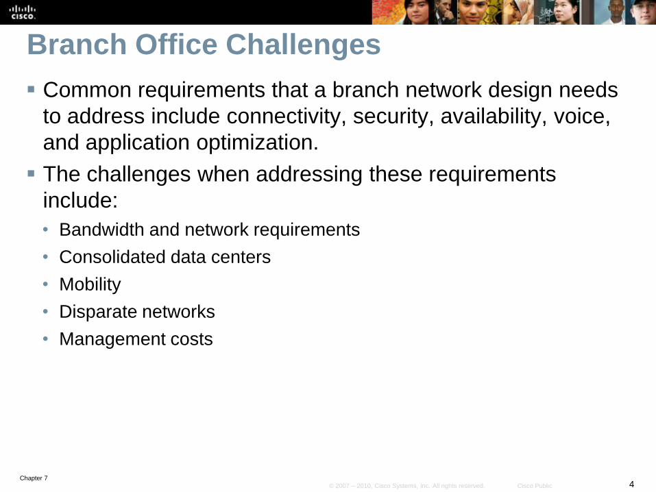
Branch Office Challenges
Common requirements that a branch network design needs
to address include connectivity, security, availability, voice,
and application optimization.
The challenges when addressing these requirements
include:
• Bandwidth and network requirements
• Consolidated data centers
• Mobility
• Disparate networks
• Management costs

Chapter 75© 2007 – 2010, Cisco Systems, Inc. All rights reserved. Cisco Public
Branch Office Design Considerations
Areas affecting branch office design include:
Branch Routing Design
Connectivity Technologies
Resiliency
Routing Protocols
Service Mix
Security and Compliance
Mobility Requirements

Chapter 76© 2007 – 2010, Cisco Systems, Inc. All rights reserved. Cisco Public
The Thin Branch
The “thin branch” is a trend that is increasing in popularity
and is mostly due to data centers and branch
consolidations.
Services which were either provided on servers or
appliances can now be deployed on a Cisco ISR including:
• Voice
• Application firewall
• Intrusion prevention
• Virtual private network
• WAN optimization
• Wireless
• WAN backup
This approach has no impact on end-user productivity.

Chapter 77© 2007 – 2010, Cisco Systems, Inc. All rights reserved. Cisco Public
Benefits of an ISR
ISRs reduce costs by deploying a single, resilient system for
fast, secure delivery of multiple mission-critical business
services, including:
• Data
• Voice
• Security
• Wireless
Chapter 78© 2007 – 2010, Cisco Systems, Inc. All rights reserved. Cisco Public
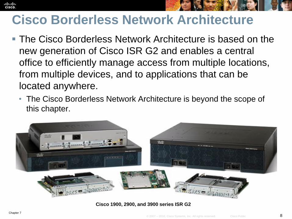
Cisco Borderless Network Architecture
The Cisco Borderless Network Architecture is based on the
new generation of Cisco ISR G2 and enables a central
office to efficiently manage access from multiple locations,
from multiple devices, and to applications that can be
located anywhere.
• The Cisco Borderless Network Architecture is beyond the scope of
this chapter.
Cisco 1900, 2900, and 3900 series ISR G2

Chapter 79© 2007 – 2010, Cisco Systems, Inc. All rights reserved. Cisco Public
WAN Requirements
The type of remote site also influences WAN requirements.
For example:
• A regional site is more likely to require primary and backup links, with
routing protocols selecting the best path while a branch site is more
likely use a VPN link and static routes.

Chapter 710© 2007 – 2010, Cisco Systems, Inc. All rights reserved. Cisco Public
WAN Requirements
Branch offices can use diverse applications including
mission-critical applications, real-time collaboration, voice,
video, videoconferencing, e-mail, and web-based
applications.
• For this reason, branch sites typically require high-bandwidth
connections.
Chapter 711© 2007 – 2010, Cisco Systems, Inc. All rights reserved. Cisco Public
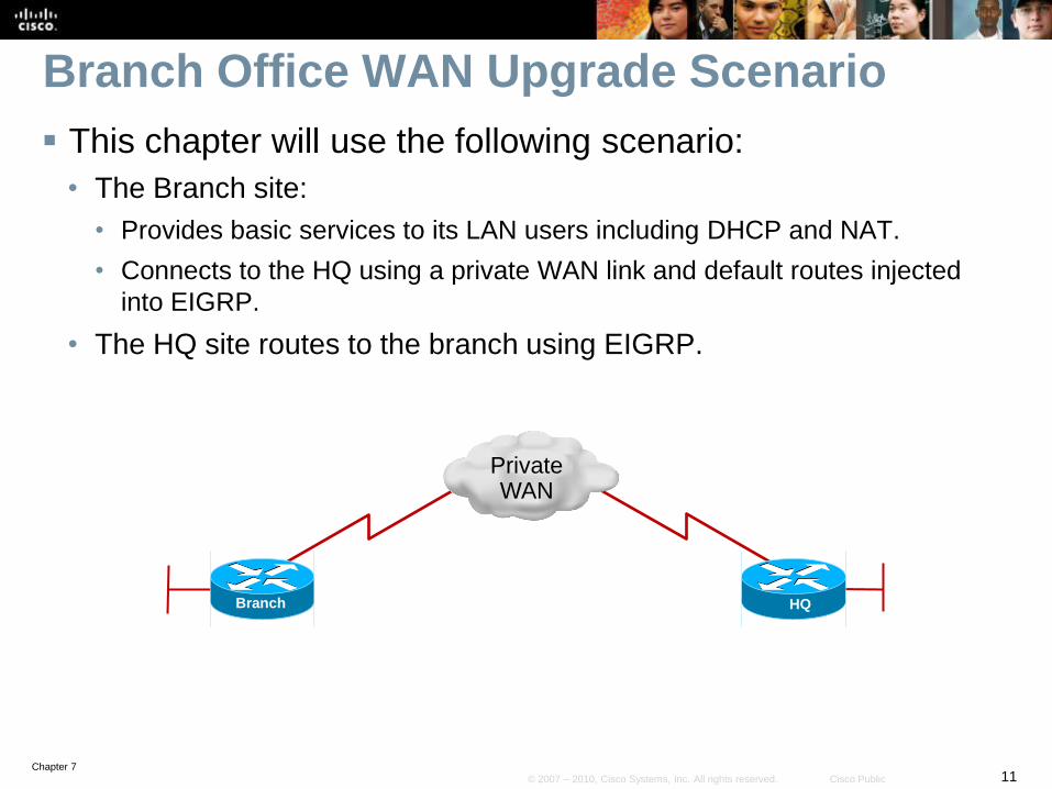
Branch Office WAN Upgrade Scenario
This chapter will use the following scenario:
• The Branch site:
• Provides basic services to its LAN users including DHCP and NAT.
• Connects to the HQ using a private WAN link and default routes injected
into EIGRP.
• The HQ site routes to the branch using EIGRP.
Branch HQ
Private WAN

Chapter 712© 2007 – 2010, Cisco Systems, Inc. All rights reserved. Cisco Public
WAN Upgrade Scenario
Redundancy would allow for a more resilient branch
architecture, therefore the Branch site will be upgraded to
use a second link through the Internet.
This second connection will be provided using a broadband
link that will be secured using an IPsec VPN.
Branch HQ
Private WAN
Internet

Chapter 713© 2007 – 2010, Cisco Systems, Inc. All rights reserved. Cisco Public
Implementation Plan
1. Deploy broadband connectivity
2. Configure static routing
3. Document and verify other services
4. Implement and tune the IPsec VPN
5. Configure GRE tunnels
Note:
• The implementation in this chapter is not exhaustive and other
solutions could also be applied.
• The following is to serve as a guide and as just one possible solution
to routing to a branch site.
Chapter 714© 2007 – 2010, Cisco Systems, Inc. All rights reserved. Cisco Public
Implementation Plan
1. Deploy broadband connectivity
2. Configure static routing
3. Document and verify other services
4. Implement and tune the IPsec VPN
5. Configure GRE tunnels
Chapter 715© 2007 – 2010, Cisco Systems, Inc. All rights reserved. Cisco Public
Deploying Broadband Technology
The choice of access network technology and suitable
bandwidth should be the first consideration addressed when
connecting a branch.
This choice is ultimately affected by:
• What is locally available.
• The cost of the link
• Data and voice requirements of the business.
Broadband technologies provide always-on access which
can support enhanced voice and video services.
• However, they may not provide the most secure connections which is
why they are often combined with IPsec or SSL VPNs.

Chapter 716© 2007 – 2010, Cisco Systems, Inc. All rights reserved. Cisco Public
Broadband Technology Options
Satellite broadband:
• A satellite modem transmits radio signals to a geosynchronous
satellite and provides a local Ethernet connection.
Broadband cable access:
• A special cable modem separates the Internet data signal from the
other signals carried on the cable and provides a local Ethernet
connection.
Digital subscriber line (DSL):
• A special high-speed modem separates the DSL data signal from the
telephone signal and provides a local Ethernet connection.

Chapter 717© 2007 – 2010, Cisco Systems, Inc. All rights reserved. Cisco Public
Wireless Broadband
New developments in broadband wireless technology are
increasing wireless availability.
Popular deployments include:
• Municipal Wi-Fi
• WiMAX
• Satellite Internet
Note:
• This list is not exhaustive and other types of wireless connectivity also
exist.

Chapter 718© 2007 – 2010, Cisco Systems, Inc. All rights reserved. Cisco Public
Municipal WiFi
Some municipal
governments provide
municipal wireless
networks.
These networks typically
provide high-speed
Internet access at no cost
or for substantially less
than other broadband
services.
Networks may be reserved
only for official use by
police, firefighters, and city
workers.

Chapter 719© 2007 – 2010, Cisco Systems, Inc. All rights reserved. Cisco Public
Municipal WiFi
Networks use a mesh topology rather than a hub-and-spoke model providing many benefits including:
• Installation is easier and can be less expensive because there are fewer wires.
• Deployment over a large urban area is faster.
• It is more reliable (If a node fails, others in the mesh compensate for it).
Chapter 720© 2007 – 2010, Cisco Systems, Inc. All rights reserved. Cisco Public
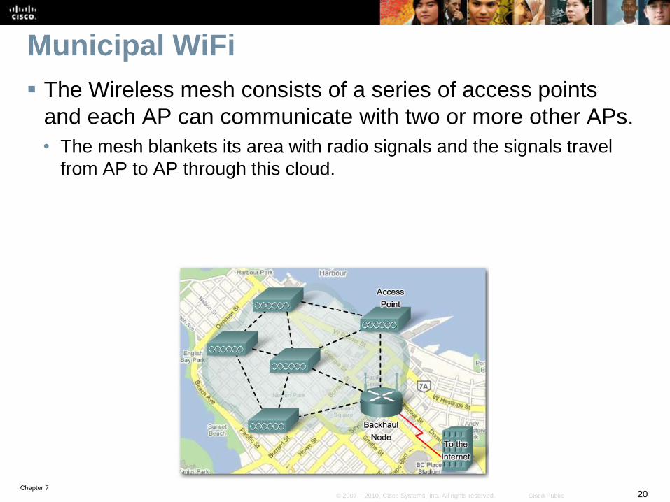
Municipal WiFi
The Wireless mesh consists of a series of access points
and each AP can communicate with two or more other APs.
• The mesh blankets its area with radio signals and the signals travel
from AP to AP through this cloud.
Chapter 721© 2007 – 2010, Cisco Systems, Inc. All rights reserved. Cisco Public
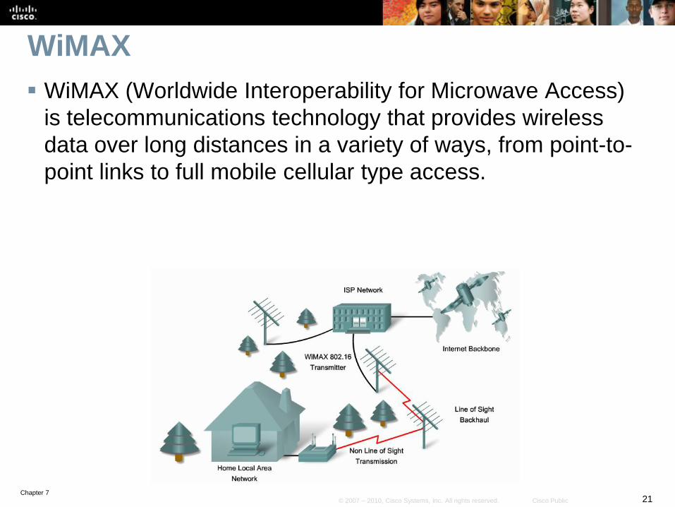
WiMAX
WiMAX (Worldwide Interoperability for Microwave Access)
is telecommunications technology that provides wireless
data over long distances in a variety of ways, from point-to-
point links to full mobile cellular type access.

Chapter 722© 2007 – 2010, Cisco Systems, Inc. All rights reserved. Cisco Public
WiMAX Components
A tower that is similar in
concept to a cellular
telephone tower.
• A single WiMAX tower can
provide coverage to an area
as large 7,500 square
kilometers (approximately
3,000 square miles).
A WiMAX receiver that is
similar in size and shape
to a PCMCIA card, or built
in to a laptop or other
wireless device.

Chapter 723© 2007 – 2010, Cisco Systems, Inc. All rights reserved. Cisco Public
Satellite Internet
Two-way satellite access is available worldwide and used in
locations where land-based Internet access is not available,
or for temporary installations.
• Internet access can be provided to vessels at sea, airplanes in flight,
and vehicles moving on land.
There are three ways to connect to the Internet using
satellites:
• One-way multicast satellite Internet systems in which information is
“pushed” to end-user sites and full interactivity is not possible.
• One-way terrestrial return satellite Internet systems use telephone
modems to send outbound data and receive downloads from the
satellite.
• Two-way satellite Internet sends data from remote sites via satellite to
a hub, which then sends the data to the Internet.
• Two-way is the most common and practical implementation.
Chapter 724© 2007 – 2010, Cisco Systems, Inc. All rights reserved. Cisco Public
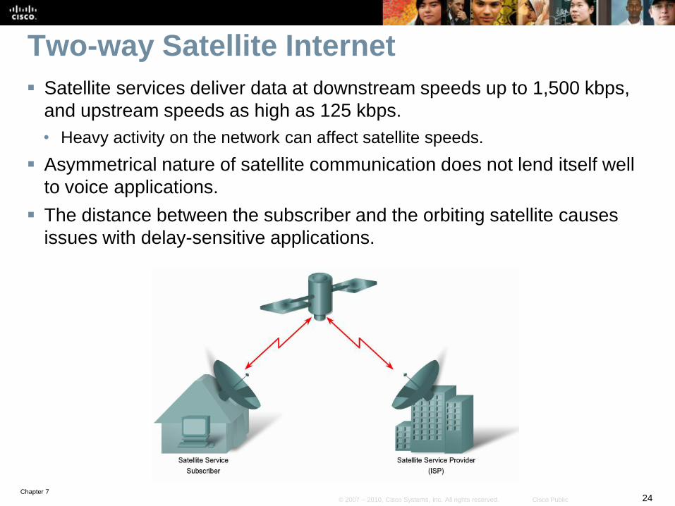
Two-way Satellite Internet
Satellite services deliver data at downstream speeds up to 1,500 kbps,
and upstream speeds as high as 125 kbps.
• Heavy activity on the network can affect satellite speeds.
Asymmetrical nature of satellite communication does not lend itself well
to voice applications.
The distance between the subscriber and the orbiting satellite causes
issues with delay-sensitive applications.
Chapter 725© 2007 – 2010, Cisco Systems, Inc. All rights reserved. Cisco Public
Broadband Cable
Broadband cable is a popular option used by teleworkers to
access enterprise networks.
• Although this solution still is not popular for connecting branch sites, it
should nonetheless be considered as the technology matures.
The cable system uses a coaxial cable that carries radio
frequency (RF) signals across the network.
Coaxial cable is the primary medium used to build cable TV
systems.

Chapter 726© 2007 – 2010, Cisco Systems, Inc. All rights reserved. Cisco Public
History of Cable Technology Cable television was first employed in
Mahanoy, Pennsylvania in 1948 by John
Walson.
• He owned an appliance store and needed
to solve poor over-the-air reception
experienced by customers receiving TV
signals from Philadelphia.
• Walson erected an antenna on a
mountaintop utility pole that enabled his
store to receive strong broadcasts from the
Philadelphia stations.
• He then connected several of his
customers who were located along the
cable path.
Walson’s is recognized as the founder of
the cable television industry.
He was also the first:
• Cable operator to use microwave to import
distant television stations
• To use coaxial cable to improve picture
quality
• To distribute pay television programming.
Chapter 727© 2007 – 2010, Cisco Systems, Inc. All rights reserved. Cisco Public
Modern Cable System
Modern cable systems provide two-way communication
between subscribers and the cable operator.
• Enables the cable operator to provide high-speed Internet access,
digital cable television, and residential telephone service.
A modern cable network is capable of sending signals on
the cable in either direction at the same time.
• Downstream: The direction of an RF signal transmission (TV
channels and data) from the source (headend) to the destination
(subscribers).
• Transmission from source to destination is called the forward path.
• Upstream: The direction of the RF signal transmission from
subscribers to the headend, or the return or reverse path.
Chapter 728© 2007 – 2010, Cisco Systems, Inc. All rights reserved. Cisco Public
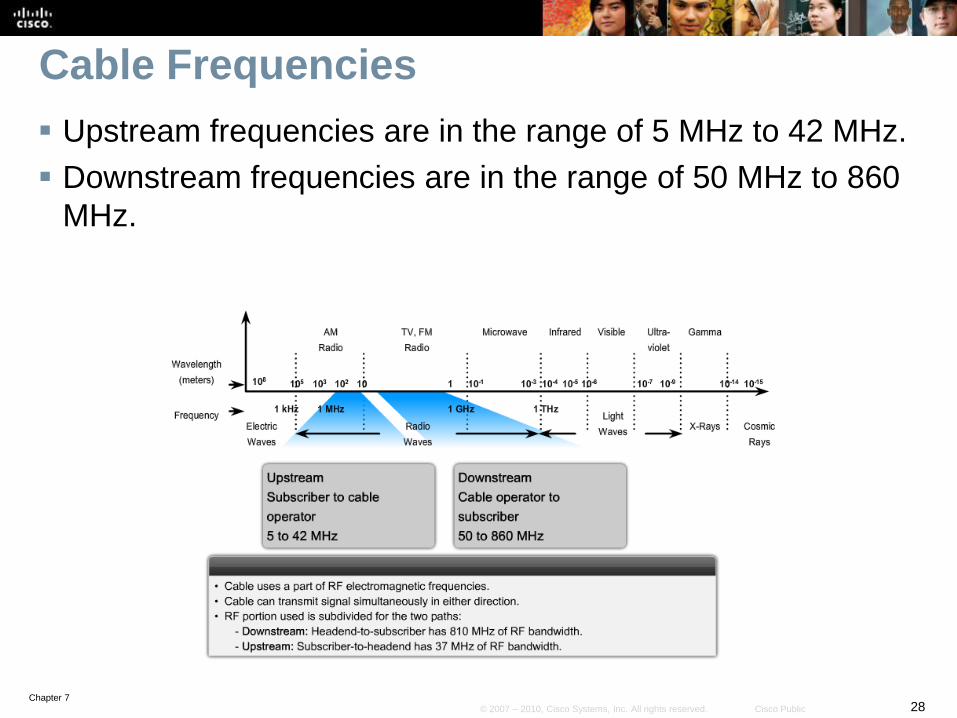
Cable Frequencies
Upstream frequencies are in the range of 5 MHz to 42 MHz.
Downstream frequencies are in the range of 50 MHz to 860
MHz.

Chapter 729© 2007 – 2010, Cisco Systems, Inc. All rights reserved. Cisco Public
Broadband Cable Components
There are two types of equipment required on a cable system:
• Cable modem termination system (CMTS) at the cable operator end.
• Cable modem (CM) on the subscriber end.
A CMTS communicates with CMs located in subscriber homes.
• The headend is actually a router with databases providing Internet
services to cable subscribers.

Chapter 730© 2007 – 2010, Cisco Systems, Inc. All rights reserved. Cisco Public
Broadband Cable Plant
The architecture consists of a hybrid fiber-coaxial (HFC) network in which optical fiber replaces the lower-bandwidth coaxial.
• A web of fiber trunk cables connects the headend to the nodes where optical-to-RF signal conversion takes place.
• Coaxial feeder cables from the node carry RF signals to the subscribers.

Chapter 731© 2007 – 2010, Cisco Systems, Inc. All rights reserved. Cisco Public
Broadband Cable
In a modern HFC network, typically 500 to 2000 active data
subscribers are connected to a cable network segment, all
sharing the upstream and downstream bandwidth.
When high usage causes congestion, the cable operator
can add additional bandwidth for data services by allocating
an additional TV channel for high-speed data.
• This addition may effectively double the downstream bandwidth that is
available to subscribers.
• Another option is to reduce the number of subscribers served by each
network segment and increase the number of fiber-optic connections.

Chapter 732© 2007 – 2010, Cisco Systems, Inc. All rights reserved. Cisco Public
Digital Subscriber Line (DSL)
DSL is a family of broadband technologies that provides
digital data transmission over the wires of a local telephone
network.
• DSL service is delivered simultaneously with regular telephone on the
same telephone line.
It has become an efficient and effective option for corporate
Internet access.
Note:
• DSL will be used as the solution for the branch office scenario.
Chapter 733© 2007 – 2010, Cisco Systems, Inc. All rights reserved. Cisco Public
DSL Background Information
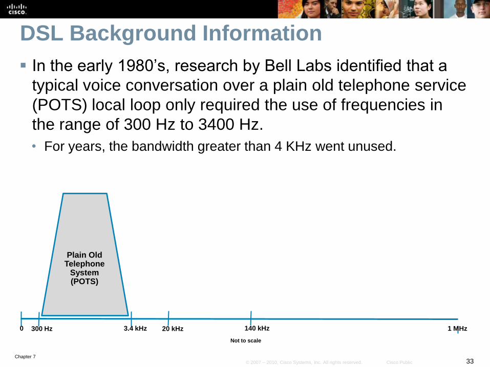
In the early 1980’s, research by Bell Labs identified that a
typical voice conversation over a plain old telephone service
(POTS) local loop only required the use of frequencies in
the range of 300 Hz to 3400 Hz.
• For years, the bandwidth greater than 4 KHz went unused.
0 20 kHz 1 MHz
Not to scale
300 Hz 3.4 kHz 140 kHz
Plain OldTelephone
System(POTS)
Chapter 734© 2007 – 2010, Cisco Systems, Inc. All rights reserved. Cisco Public
DSL Background Information
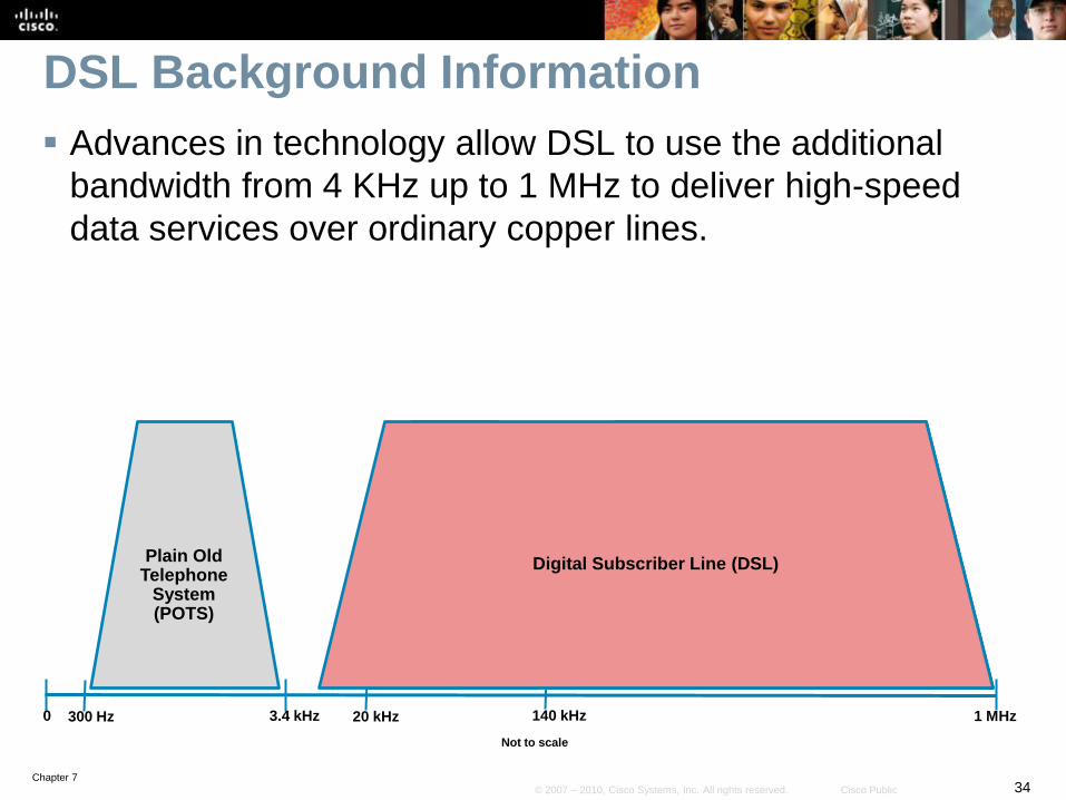
Advances in technology allow DSL to use the additional
bandwidth from 4 KHz up to 1 MHz to deliver high-speed
data services over ordinary copper lines.
UpstreamADSL
0 20 kHz 1 MHz
Not to scale
300 Hz 3.4 kHz
Downstream ADSL
140 kHz
Digital Subscriber Line (DSL)Plain OldTelephone
System(POTS)

Chapter 735© 2007 – 2010, Cisco Systems, Inc. All rights reserved. Cisco Public
DSL Variants
There are many variants of DSL that are distinguished by
their nature, maximum data rate, data and voice support,
line coding technology and maximum distance.
DSL Variants * NatureMaximum Data Rates
(Downstream / Upstream)
ADSL(Asymmetric DSL)
Asymmetric 8 Mbps / 1 Mbps
HDSL(high bitrate DSL)
Symmetric 2 Mbps / 2 Mbps
SDSL(Symmetric DSL )
Symmetric 2 Mbps / 2 Mbps
SHDSL(Single-pair high-speed DSL)
Symmetric 2.3 Mbps / 2.3 Mbps
VDSL(Very High bitrate DSL)
Symmetric / Asymmetric 52 Mbps / 16 Mbps
* Partial List
Chapter 736© 2007 – 2010, Cisco Systems, Inc. All rights reserved. Cisco Public
Asymmetric DSL (ADSL) Frequencies
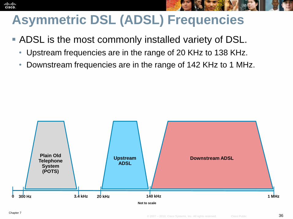
ADSL is the most commonly installed variety of DSL.
• Upstream frequencies are in the range of 20 KHz to 138 KHz.
• Downstream frequencies are in the range of 142 KHz to 1 MHz.
UpstreamADSL
0 20 kHz 1 MHz
Not to scale
300 Hz 3.4 kHz
Downstream ADSL
140 kHz
Plain OldTelephone
System(POTS)

Chapter 737© 2007 – 2010, Cisco Systems, Inc. All rights reserved. Cisco Public
ADSL Infrastructure
ADSL is not a complete end-to-end solution.
• All variants use a similar infrastructure.
The customer requires an ADSL modem or router with an
ADSL card.
• Voice traffic is filtered using an inline microfilter.

Chapter 738© 2007 – 2010, Cisco Systems, Inc. All rights reserved. Cisco Public
ADSL Infrastructure
The ADSL connection is deployed in the “last mile” of a
local telephone network.
• This is the area between the customers premise equipment (CPE)
and the DSL Access Multiplexer (DSLAM).

Chapter 739© 2007 – 2010, Cisco Systems, Inc. All rights reserved. Cisco Public
ADSL Infrastructure
A POTS splitter is a passive device (requires no power) installed
at the central office (CO) to separate the POTS voice signal
and ADSL signal.
• POTS traffic is forwarded to the Class 5 voice switch.
• ADSL traffic is forwarded to the DSLAM.
Chapter 740© 2007 – 2010, Cisco Systems, Inc. All rights reserved. Cisco Public
ADSL Infrastructure
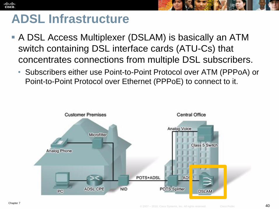
A DSL Access Multiplexer (DSLAM) is basically an ATM
switch containing DSL interface cards (ATU-Cs) that
concentrates connections from multiple DSL subscribers.
• Subscribers either use Point-to-Point Protocol over ATM (PPPoA) or
Point-to-Point Protocol over Ethernet (PPPoE) to connect to it.
Chapter 741© 2007 – 2010, Cisco Systems, Inc. All rights reserved. Cisco Public
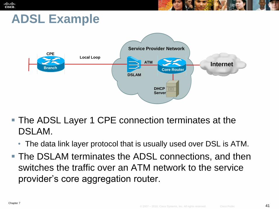
ADSL Example
The ADSL Layer 1 CPE connection terminates at the
DSLAM.
• The data link layer protocol that is usually used over DSL is ATM.
The DSLAM terminates the ADSL connections, and then
switches the traffic over an ATM network to the service
provider’s core aggregation router.
DSLAM
Local Loop
Service Provider Network
ATM
Core Router
DHCP Server
InternetBranch
CPE

Chapter 742© 2007 – 2010, Cisco Systems, Inc. All rights reserved. Cisco Public
ADSL Example
There are three ways to encapsulate IP packets over an
ATM and DSL connection:
• RFC 1483/2684 Bridged
• Unpopular due to security and scalability issues.
• PPP over Ethernet (PPPoE)
• PPP over ATM (PPPoA)
DSLAM
Local Loop
Service Provider Network
ATM
Core Router
DHCP Server
InternetBranch
CPE

Chapter 743© 2007 – 2010, Cisco Systems, Inc. All rights reserved. Cisco Public
ADSL PPPoA Example
The PPP connection is established between the CPE and
the core router.
The CPE device is configured with a username and
password.
The core router authenticates the users using either a local
database or an external RADIUS AAA server.
DSLAM
Local Loop
Service Provider Network
ATM
Core Router
DHCP Server
InternetBranch
CPE

Chapter 744© 2007 – 2010, Cisco Systems, Inc. All rights reserved. Cisco Public
ADSL PPPoA Example
Once authenticated, the PPP Internet Protocol Control
Protocol (IPCP) negotiation takes place to assign an IP
address to the CPE.
• The core router will provide an IP address from its DHCP server.
• The CPE can use NAT or PAT to support multiple inside hosts.
DSLAM
Local Loop
Service Provider Network
ATM
Core Router
DHCP Server
InternetBranch
CPE
Chapter 745© 2007 – 2010, Cisco Systems, Inc. All rights reserved. Cisco Public
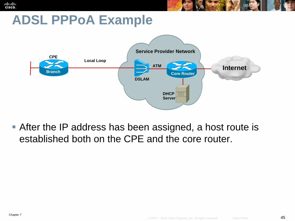
ADSL PPPoA Example
After the IP address has been assigned, a host route is
established both on the CPE and the core router.
DSLAM
Local Loop
Service Provider Network
ATM
Core Router
DHCP Server
InternetBranch
CPE
Chapter 746© 2007 – 2010, Cisco Systems, Inc. All rights reserved. Cisco Public
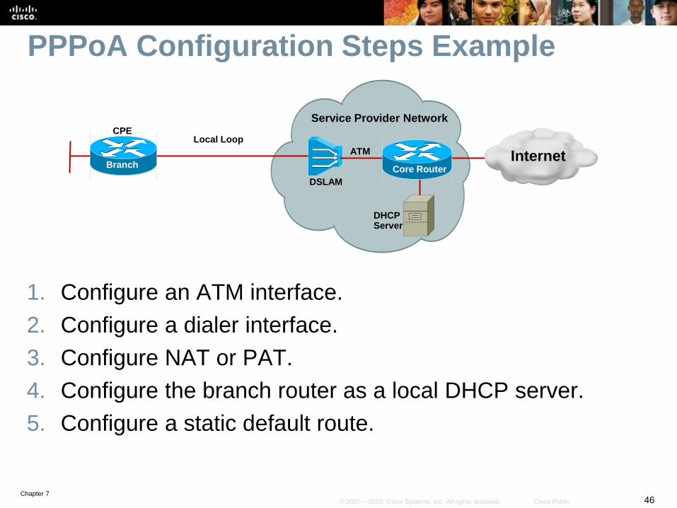
PPPoA Configuration Steps Example
1. Configure an ATM interface.
2. Configure a dialer interface.
3. Configure NAT or PAT.
4. Configure the branch router as a local DHCP server.
5. Configure a static default route.
DSLAM
Local Loop
Service Provider Network
ATM
Core Router
DHCP Server
InternetBranch
CPE
Chapter 747© 2007 – 2010, Cisco Systems, Inc. All rights reserved. Cisco Public
Configure ATM and Dialer Interfaces
DSLAM
Service Provider Network
ATM
Core Router
DHCP Server
InternetBranch
CPE192.168.1.0 /24
ATM 0/0
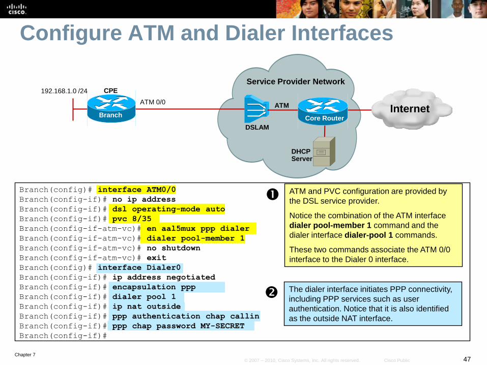
ATM and PVC configuration are provided by
the DSL service provider.
Notice the combination of the ATM interface
dialer pool-member 1 command and the
dialer interface dialer-pool 1 commands.
These two commands associate the ATM 0/0
interface to the Dialer 0 interface.
Branch(config)# interface ATM0/0
Branch(config-if)# no ip address
Branch(config-if)# dsl operating-mode auto
Branch(config-if)# pvc 8/35
Branch(config-if-atm-vc)# en aal5mux ppp dialer
Branch(config-if-atm-vc)# dialer pool-member 1
Branch(config-if-atm-vc)# no shutdown
Branch(config-if-atm-vc)# exit
Branch(config)# interface Dialer0
Branch(config-if)# ip address negotiated
Branch(config-if)# encapsulation ppp
Branch(config-if)# dialer pool 1
Branch(config-if)# ip nat outside
Branch(config-if)# ppp authentication chap callin
Branch(config-if)# ppp chap password MY-SECRET
Branch(config-if)#
The dialer interface initiates PPP connectivity,
including PPP services such as user
authentication. Notice that it is also identified
as the outside NAT interface.

Chapter 748© 2007 – 2010, Cisco Systems, Inc. All rights reserved. Cisco Public
Configure NAT, DHCP, and Routing
DSLAM
Service Provider Network
ATM
Core Router
DHCP Server
InternetBranch
CPE192.168.1.0 /24
ATM 0/0
Branch(config)# ip nat inside source list 101 interface Dialer0 overload
Branch(config)# access-list 101 permit ip 192.168.1.0 0.0.0.255 any
Branch(config)#
Branch(config)# ip dhcp pool MY-POOL
Branch(dhcp-config)# network 192.168.1.0 255.255.255.0
Branch(dhcp-config)# default-router 192.168.1.1
Branch(dhcp-config)# exit
Branch(config)# ip route 0.0.0.0 0.0.0.0 Dialer0
Branch(config)#
The Branch router provides DHCP services to users connected to the inside LAN interface using the 192.168.1.0 pool.
The PAT configuration permits the inside IP addresses to share the outside IP address.
The static default route points to the dialer interface therefore routed traffic will trigger the dialer interface to activate.

Chapter 749© 2007 – 2010, Cisco Systems, Inc. All rights reserved. Cisco Public
Verifying PPPoA
Confirm that the branch router has a route pointing to the dialer interface using the show ip route command.
• Verify IP connectivity using the ping and traceroute commands
from an inside host to confirm proper PAT translation.
Use the debug ppp authentication command to
debug the PPP session authentication.
Verify ATM connectivity using the debug atm events
command.
Finally, check Layer 1 connectivity and discover the DSL line status using the show dsl interface atm
command.
Chapter 750© 2007 – 2010, Cisco Systems, Inc. All rights reserved. Cisco Public
Implementation Plan
1. Deploy broadband connectivity
2. Configure static routing
3. Document and verify other services
4. Implement and tune the IPsec VPN
5. Configure GRE tunnels
Note:
For simplicity reasons, the ADSL Internet link implemented
in the previous step will be replaced by a Serial link.
Chapter 751© 2007 – 2010, Cisco Systems, Inc. All rights reserved. Cisco Public
Branch Static Routing Example
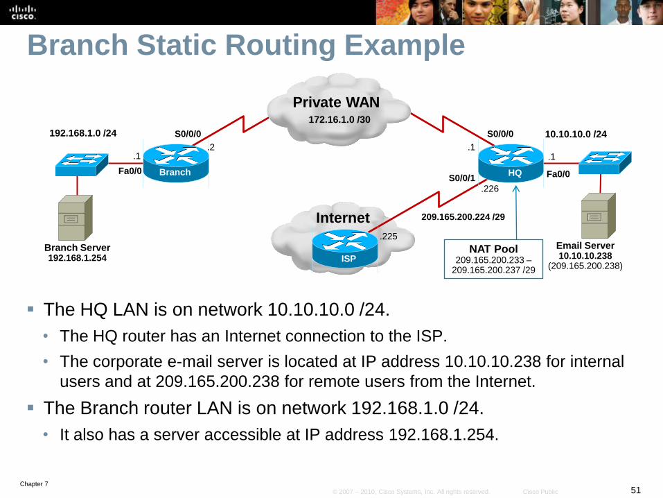
The HQ LAN is on network 10.10.10.0 /24.
• The HQ router has an Internet connection to the ISP.
• The corporate e-mail server is located at IP address 10.10.10.238 for internal
users and at 209.165.200.238 for remote users from the Internet.
The Branch router LAN is on network 192.168.1.0 /24.
• It also has a server accessible at IP address 192.168.1.254.
Internet
Branch HQ
Branch Server192.168.1.254
S0/0/0192.168.1.0 /24172.16.1.0 /30
10.10.10.0 /24
Fa0/0
.1.1 .1
.2
Fa0/0
S0/0/0
209.165.200.224 /29
S0/0/1
.225
.226
ISP
Email Server10.10.10.238
(209.165.200.238)
NAT Pool209.165.200.233 –
209.165.200.237 /29
Private WAN172.16.1.0 /30
Chapter 752© 2007 – 2010, Cisco Systems, Inc. All rights reserved. Cisco Public
Branch Static Routing Example
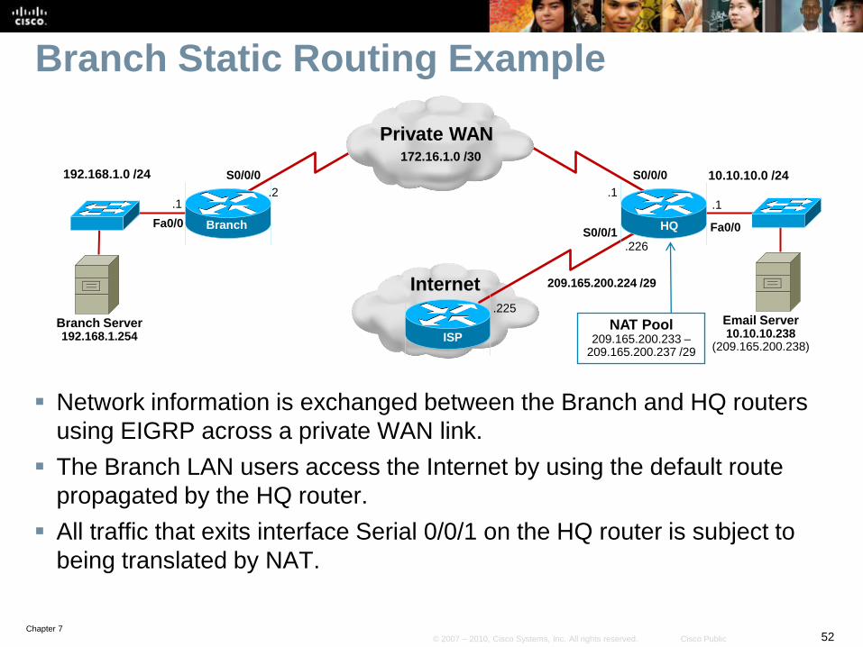
Network information is exchanged between the Branch and HQ routers
using EIGRP across a private WAN link.
The Branch LAN users access the Internet by using the default route
propagated by the HQ router.
All traffic that exits interface Serial 0/0/1 on the HQ router is subject to
being translated by NAT.
Internet
Branch HQ
Branch Server192.168.1.254
S0/0/0192.168.1.0 /24172.16.1.0 /30
10.10.10.0 /24
Fa0/0
.1.1 .1
.2
Fa0/0
S0/0/0
209.165.200.224 /29
S0/0/1
.225
.226
ISP
Email Server10.10.10.238
(209.165.200.238)
NAT Pool209.165.200.233 –
209.165.200.237 /29
Private WAN172.16.1.0 /30
Chapter 753© 2007 – 2010, Cisco Systems, Inc. All rights reserved. Cisco Public
Branch Static Routing Example
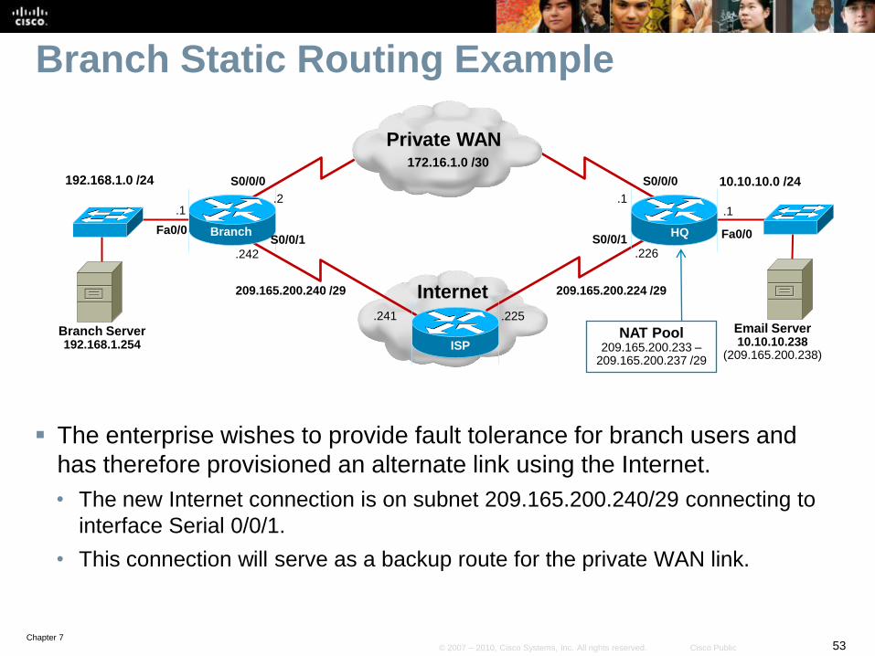
The enterprise wishes to provide fault tolerance for branch users and
has therefore provisioned an alternate link using the Internet.
• The new Internet connection is on subnet 209.165.200.240/29 connecting to
interface Serial 0/0/1.
• This connection will serve as a backup route for the private WAN link.
Internet
Branch HQ
Branch Server192.168.1.254
S0/0/0192.168.1.0 /24172.16.1.0 /30
10.10.10.0 /24
S0/0/1Fa0/0
.242
.1.1 .1
.2
Fa0/0
S0/0/0
209.165.200.224 /29
.241
S0/0/1
209.165.200.240 /29
.225
.226
ISP
Email Server10.10.10.238
(209.165.200.238)
NAT Pool209.165.200.233 –
209.165.200.237 /29
Private WAN172.16.1.0 /30

Chapter 754© 2007 – 2010, Cisco Systems, Inc. All rights reserved. Cisco Public
Verifying EIGRP
Branch# show ip protocols
Routing Protocol is "eigrp 1"
Outgoing update filter list for all interfaces is not set
Incoming update filter list for all interfaces is not set
Default networks flagged in outgoing updates
Default networks accepted from incoming updates
EIGRP metric weight K1=1, K2=0, K3=1, K4=0, K5=0
EIGRP maximum hopcount 100
EIGRP maximum metric variance 1
Redistributing: eigrp 1
EIGRP NSF-aware route hold timer is 240s
Automatic network summarization is not in effect
Maximum path: 4
Routing for Networks:
172.16.1.0/30
192.168.1.0
Routing Information Sources:
Gateway Distance Last Update
172.16.1.1 90 00:08:19
Distance: internal 90 external 170
Branch#

Chapter 755© 2007 – 2010, Cisco Systems, Inc. All rights reserved. Cisco Public
Verifying EIGRP
Branch# show ip route
*Mar 26 03:45:38.207: %SYS-5-CONFIG_I: Configured from console by consolee
Codes: C - connected, S - static, R - RIP, M - mobile, B - BGP
D - EIGRP, EX - EIGRP external, O - OSPF, IA - OSPF inter area
N1 - OSPF NSSA external type 1, N2 - OSPF NSSA external type 2
E1 - OSPF external type 1, E2 - OSPF external type 2
i - IS-IS, su - IS-IS summary, L1 - IS-IS level-1, L2 - IS-IS level-2
ia - IS-IS inter area, * - candidate default, U - per-user static route
o - ODR, P - periodic downloaded static route
Gateway of last resort is 172.16.1.1 to network 0.0.0.0
172.16.0.0/30 is subnetted, 1 subnets
C 172.16.1.0 is directly connected, Serial0/0/0
209.165.200.0/29 is subnetted, 1 subnets
C 209.165.200.240 is directly connected, Serial0/0/1
10.0.0.0/24 is subnetted, 1 subnets
D 10.10.10.0 [90/2172416] via 172.16.1.1, 00:00:17, Serial0/0/0
C 192.168.1.0/24 is directly connected, FastEthernet0/0
D*EX 0.0.0.0/0 [170/2681856] via 172.16.1.1, 00:00:17, Serial0/0/0

Chapter 756© 2007 – 2010, Cisco Systems, Inc. All rights reserved. Cisco Public
Verify Connectivity to the Email Server
Branch# ping 10.10.10.238 source 192.168.1.1
Type escape sequence to abort.
Sending 5, 100-byte ICMP Echos to 10.10.10.238, timeout is 2 seconds:
Packet sent with a source address of 192.168.1.1
!!!!!
Success rate is 100 percent (5/5), round-trip min/avg/max = 1/2/4 ms
Branch#
Branch# trace 10.10.10.238 source 192.168.1.1
Type escape sequence to abort.
Tracing the route to 10.10.10.238
1 172.16.1.1 0 msec 0 msec *
Branch#
Chapter 757© 2007 – 2010, Cisco Systems, Inc. All rights reserved. Cisco Public
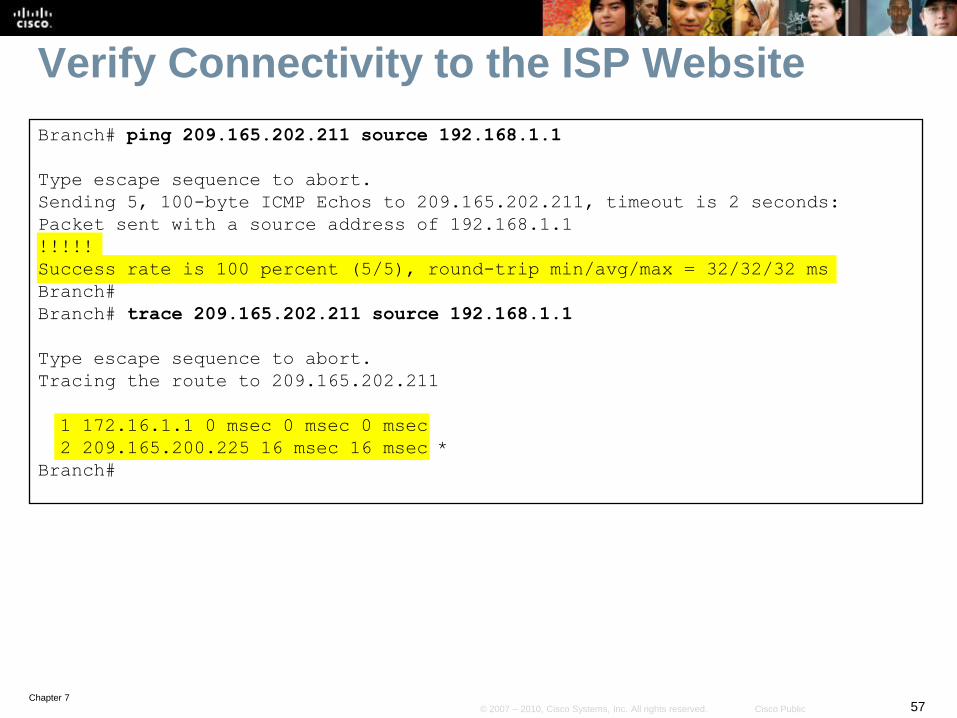
Verify Connectivity to the ISP Website
Branch# ping 209.165.202.211 source 192.168.1.1
Type escape sequence to abort.
Sending 5, 100-byte ICMP Echos to 209.165.202.211, timeout is 2 seconds:
Packet sent with a source address of 192.168.1.1
!!!!!
Success rate is 100 percent (5/5), round-trip min/avg/max = 32/32/32 ms
Branch#
Branch# trace 209.165.202.211 source 192.168.1.1
Type escape sequence to abort.
Tracing the route to 209.165.202.211
1 172.16.1.1 0 msec 0 msec 0 msec
2 209.165.200.225 16 msec 16 msec *
Branch#

Chapter 758© 2007 – 2010, Cisco Systems, Inc. All rights reserved. Cisco Public
Configure a Default Floating Static Route
To enable the Internet link should the private WAN link fail, a default
floating static route has been configured.
Notice that the assigned administrative distance is greater than the
current default route in the routing table with an administrative distance
of 170.
Internet
Branch HQ
Branch Server192.168.1.254
S0/0/0192.168.1.0 /24172.16.1.0 /30
10.10.10.0 /24
S0/0/1Fa0/0
.242
.1.1 .1
.2
Fa0/0
S0/0/0
209.165.200.224 /29
.241
S0/0/1
209.165.200.240 /29
.225
.226
ISP
Email Server10.10.10.238
(209.165.200.238)
NAT Pool209.165.200.233 –
209.165.200.237 /29
Private WAN172.16.1.0 /30
Branch(config)# ip route 0.0.0.0 0.0.0.0 209.165.200.241 171
Branch(config)# exit

Chapter 759© 2007 – 2010, Cisco Systems, Inc. All rights reserved. Cisco Public
Test the Floating Static Route
Branch# debug ip routing
IP routing debugging is on
Branch# conf t
Enter configuration commands, one per line. End with CNTL/Z.
Branch(config)# int s0/0/0
Branch(config-if)# shutdown
Branch(config-if)#
*Mar 26 06:22:23.759: RT: is_up: Serial0/0/0 0 state: 6 sub state: 1 line: 0
has_route: True
*Mar 26 06:22:23.759: RT: interface Serial0/0/0 removed from routing table
*Mar 26 06:22:23.759: RT: del 172.16.1.0/30 via 0.0.0.0, connected metric [0/0]
*Mar 26 06:22:23.759: RT: delete subnet route to 172.16.1.0/30
*Mar 26 06:22:23.759: RT: NET-RED 172.16.1.0/30
*Mar 26 06:22:23.759: RT: delete network route to 172.16.0.0
*Mar 26 06:22:23.759: RT: NET-RED 172.16.0.0/16
*Mar 26 06:22:23.759: RT: Pruning routes for Serial0/0/0 (3)
*Mar 26 06:22:23.763: RT: delete route to 10.10.10.0 via 172.16.1.1,
Serial0/0/0
*Mar 26 06:22:23.763: RT: no routes to 10.10.10.0, flushing
<Continued>

Chapter 760© 2007 – 2010, Cisco Systems, Inc. All rights reserved. Cisco Public
Test the Floating Static Route
Mar 26 06:22:23.763: RT: NET-RED 10.10.10.0/24
*Mar 26 06:22:23.767: RT: delete network route to 10.0.0.0
*Mar 26 06:22:23.767: RT: NET-RED 10.0.0.0/8
*Mar 26 06:22:23.767: RT: delete route to 0.0.0.0 via 172.16.1.1, Serial0/0/0
*Mar 26 06:22:23.767: RT: no routes to 0.0.0.0, flushing
*Mar 26 06:22:23.767: RT: NET-RED 0.0.0.0/0
*Mar 26 06:22:23.771: RT: add 0.0.0.0/0 via 209.165.200.241, static metric
[171/0]
*Mar 26 06:22:23.771: RT: NET-RED 0.0.0.0/0
*Mar 26 06:22:23.771: RT: default path is now 0.0.0.0 via 209.165.200.241
*Mar 26 06:22:23.771: RT: new default network 0.0.0.0
*Mar 26 06:22:23.771: RT: NET-RED 0.0.0.0/0
*Mar 26 06:22:23.771: %DUAL-5-NBRCHANGE: IP-EIGRP(0) 1: Neighbor 172.16.1.1
(Serial0/0/0) is down: interface down
Branch(config-if)# end
Branch# undebug all
All possible debugging has been turned off
Branch#

Chapter 761© 2007 – 2010, Cisco Systems, Inc. All rights reserved. Cisco Public
Verify the Routing Table
Branch# show ip route
Codes: C - connected, S - static, R - RIP, M - mobile, B - BGP
D - EIGRP, EX - EIGRP external, O - OSPF, IA - OSPF inter area
N1 - OSPF NSSA external type 1, N2 - OSPF NSSA external type 2
E1 - OSPF external type 1, E2 - OSPF external type 2
i - IS-IS, su - IS-IS summary, L1 - IS-IS level-1, L2 - IS-IS level-2
ia - IS-IS inter area, * - candidate default, U - per-user static route
o - ODR, P - periodic downloaded static route
Gateway of last resort is 209.165.200.241 to network 0.0.0.0
209.165.200.0/29 is subnetted, 1 subnets
C 209.165.200.240 is directly connected, Serial0/0/1
192.168.1.0/24 is variably subnetted, 2 subnets, 2 masks
C 192.168.1.0/24 is directly connected, FastEthernet0/0
S* 0.0.0.0/0 [171/0] via 209.165.200.241
Branch#
Chapter 762© 2007 – 2010, Cisco Systems, Inc. All rights reserved. Cisco Public
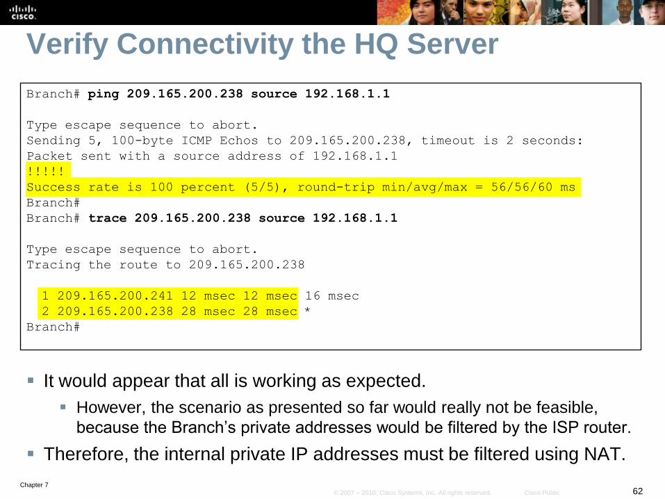
Verify Connectivity the HQ Server
Branch# ping 209.165.200.238 source 192.168.1.1
Type escape sequence to abort.
Sending 5, 100-byte ICMP Echos to 209.165.200.238, timeout is 2 seconds:
Packet sent with a source address of 192.168.1.1
!!!!!
Success rate is 100 percent (5/5), round-trip min/avg/max = 56/56/60 ms
Branch#
Branch# trace 209.165.200.238 source 192.168.1.1
Type escape sequence to abort.
Tracing the route to 209.165.200.238
1 209.165.200.241 12 msec 12 msec 16 msec
2 209.165.200.238 28 msec 28 msec *
Branch#
It would appear that all is working as expected.
However, the scenario as presented so far would really not be feasible,
because the Branch’s private addresses would be filtered by the ISP router.
Therefore, the internal private IP addresses must be filtered using NAT.
Chapter 763© 2007 – 2010, Cisco Systems, Inc. All rights reserved. Cisco Public
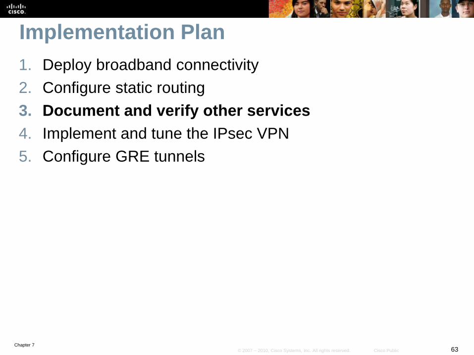
Implementation Plan
1. Deploy broadband connectivity
2. Configure static routing
3. Document and verify other services
4. Implement and tune the IPsec VPN
5. Configure GRE tunnels
Chapter 764© 2007 – 2010, Cisco Systems, Inc. All rights reserved. Cisco Public
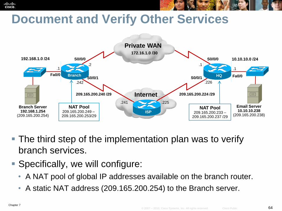
Document and Verify Other Services
The third step of the implementation plan was to verify
branch services.
Specifically, we will configure:
• A NAT pool of global IP addresses available on the branch router.
• A static NAT address (209.165.200.254) to the Branch server.
Internet
Branch HQ
S0/0/0192.168.1.0 /24172.16.1.0 /30
10.10.10.0 /24
S0/0/1Fa0/0
.242
.1.1 .1
.2
Fa0/0
S0/0/0
209.165.200.224 /29
.241
S0/0/1
209.165.200.240 /29
.225
.226
ISP
Email Server10.10.10.238
(209.165.200.238)
NAT Pool209.165.200.233 –
209.165.200.237 /29
Private WAN172.16.1.0 /30
Branch Server192.168.1.254
(209.165.200.254)
NAT Pool209.165.200.249 –209.165.200.253/29

Chapter 765© 2007 – 2010, Cisco Systems, Inc. All rights reserved. Cisco Public
Steps to Configuring NAT
1. Identify which traffic will be translated using IP ACLs.
2. Identify what to translate to using the ip nat pool command.
3. Bind the ACL and pool together using the ip nat pool inside
command.
4. Identify the inside and outside NAT interfaces using the ip nat inside
and ip nat outside commands.
Internet
Branch HQ
S0/0/0192.168.1.0 /24172.16.1.0 /30
10.10.10.0 /24
S0/0/1Fa0/0
.242
.1.1 .1
.2
Fa0/0
S0/0/0
209.165.200.224 /29
.241
S0/0/1
209.165.200.240 /29
.225
.226
ISP
Email Server10.10.10.238
(209.165.200.238)
NAT Pool209.165.200.233 –
209.165.200.237 /29
Private WAN172.16.1.0 /30
Branch Server192.168.1.254
(209.165.200.254)
NAT Pool209.165.200.249 –209.165.200.253/29

Chapter 766© 2007 – 2010, Cisco Systems, Inc. All rights reserved. Cisco Public
Configure the NAT ACL
The first step in configuring NAT is to create an ACL that
will declare which traffic will be translated.
• It is important to understand that it is not used to filter the traffic but
instead is used to designate which traffic will be translated by NAT.
• A permit statement in a NAT access list means "translate," and a deny
statement in the same access list means "do not translate.“
Internet
Branch HQ
S0/0/0192.168.1.0 /24172.16.1.0 /30
10.10.10.0 /24
S0/0/1Fa0/0
.242
.1.1 .1
.2
Fa0/0
S0/0/0
209.165.200.224 /29
.241
S0/0/1
209.165.200.240 /29
.225
.226
ISP
Email Server10.10.10.238
(209.165.200.238)
NAT Pool209.165.200.233 –
209.165.200.237 /29
Private WAN172.16.1.0 /30
Branch Server192.168.1.254
(209.165.200.254)
NAT Pool209.165.200.249 –209.165.200.253/29

Chapter 767© 2007 – 2010, Cisco Systems, Inc. All rights reserved. Cisco Public
Configure the NAT ACL Example
The ACL states that traffic with source IP address 192.168.1.0/24 is
targeted for translation by the permit statement.
• The unseen implicit deny statement will not translate any other addresses.
Internet
Branch HQ
S0/0/0192.168.1.0 /24172.16.1.0 /30
10.10.10.0 /24
S0/0/1Fa0/0
.242
.1.1 .1
.2
Fa0/0
S0/0/0
209.165.200.224 /29
.241
S0/0/1
209.165.200.240 /29
.225
.226
ISP
Email Server10.10.10.238
(209.165.200.238)
NAT Pool209.165.200.233 –
209.165.200.237 /29
Private WAN172.16.1.0 /30
Branch Server192.168.1.254
(209.165.200.254)
NAT Pool209.165.200.249 –209.165.200.253/29
Branch(config)# ip access-list extended BRANCH-NAT-ACL
Branch(config-ext-nacl)# permit ip 192.168.1.0 0.0.0.255 any
Branch(config-ext-nacl)# exit

Chapter 768© 2007 – 2010, Cisco Systems, Inc. All rights reserved. Cisco Public
Configure a NAT Pool
Specify criteria to be matched using ACLs or prefix lists.
Router(config)#
ip nat pool name start-ip end-ip {netmask netmask |
prefix-length prefix-length}
Parameter Description
name IP route prefix for the destination.
start-ip Starting IP address of the address pool.
end-ip Ending IP address of the address pool.
netmask netmaskIndicates which address bits that belong to the network and
subnetwork fields and which bits belong to the host field.
prefix-length
prefix-lengthIndicates the netmask using the prefix length.
type rotary
Indicates that the range of addresses in the address pool
identifies inside hosts on which TCP load distribution will
occur.

Chapter 769© 2007 – 2010, Cisco Systems, Inc. All rights reserved. Cisco Public
Bind the ACL and NAT Pool Link the source IP addresses to the pool for dynamic address translation.
Router(config)#
ip nat inside source {list {access-list-number | access-
list-name} | route-map name} {interface type number | pool
name} [overload]
Parameter Description
name IP route prefix for the destination.
list access-list-number
| access-list-nameNumber or name of a standard IP access list.
route-map name Specifies the named route map.
interface type number Specifies the interface type and number.
pool name Name of pool from which addresses are allocated.
overload (Optional) Enables the tracking of TCP or UDP port
numbers.
Chapter 770© 2007 – 2010, Cisco Systems, Inc. All rights reserved. Cisco Public
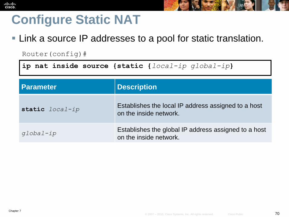
Configure Static NAT
Link a source IP addresses to a pool for static translation.
Router(config)#
ip nat inside source {static {local-ip global-ip}
Parameter Description
static local-ipEstablishes the local IP address assigned to a host
on the inside network.
global-ipEstablishes the global IP address assigned to a host
on the inside network.

Chapter 771© 2007 – 2010, Cisco Systems, Inc. All rights reserved. Cisco Public
Identify NAT Interfaces
Designate the NAT inside and outside interfaces.
Router(config-if)#
ip nat inside [inside | outside]
Parameter Description
insideIndicates that the interface is connected to the inside
network (the network subject to NAT translation).
outsideIndicates that the interface is connected to the
outside network.
Chapter 772© 2007 – 2010, Cisco Systems, Inc. All rights reserved. Cisco Public
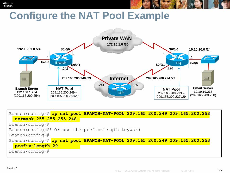
Configure the NAT Pool Example
Internet
Branch HQ
S0/0/0192.168.1.0 /24172.16.1.0 /30
10.10.10.0 /24
S0/0/1Fa0/0
.242
.1.1 .1
.2
Fa0/0
S0/0/0
209.165.200.224 /29
.241
S0/0/1
209.165.200.240 /29
.225
.226
ISP
Email Server10.10.10.238
(209.165.200.238)
NAT Pool209.165.200.233 –
209.165.200.237 /29
Private WAN172.16.1.0 /30
Branch Server192.168.1.254
(209.165.200.254)
NAT Pool209.165.200.249 –209.165.200.253/29
Branch(config)# ip nat pool BRANCH-NAT-POOL 209.165.200.249 209.165.200.253
netmask 255.255.255.248
Branch(config)#
Branch(config)#! Or use the prefix-length keyword
Branch(config)#
Branch(config)# ip nat pool BRANCH-NAT-POOL 209.165.200.249 209.165.200.253
prefix-length 29
Branch(config)#
Chapter 773© 2007 – 2010, Cisco Systems, Inc. All rights reserved. Cisco Public
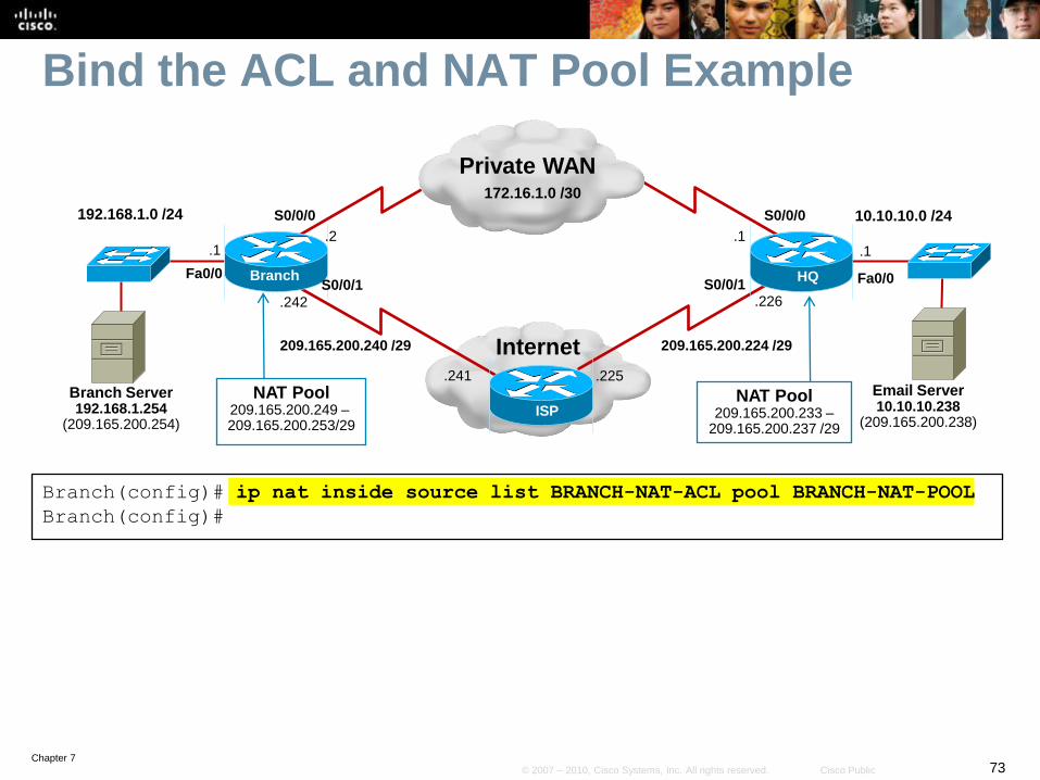
Bind the ACL and NAT Pool Example
Internet
Branch HQ
S0/0/0192.168.1.0 /24172.16.1.0 /30
10.10.10.0 /24
S0/0/1Fa0/0
.242
.1.1 .1
.2
Fa0/0
S0/0/0
209.165.200.224 /29
.241
S0/0/1
209.165.200.240 /29
.225
.226
ISP
Email Server10.10.10.238
(209.165.200.238)
NAT Pool209.165.200.233 –
209.165.200.237 /29
Private WAN172.16.1.0 /30
Branch Server192.168.1.254
(209.165.200.254)
NAT Pool209.165.200.249 –209.165.200.253/29
Branch(config)# ip nat inside source list BRANCH-NAT-ACL pool BRANCH-NAT-POOL
Branch(config)#

Chapter 774© 2007 – 2010, Cisco Systems, Inc. All rights reserved. Cisco Public
Configure Static NAT for the Server
Internet
Branch HQ
S0/0/0192.168.1.0 /24172.16.1.0 /30
10.10.10.0 /24
S0/0/1Fa0/0
.242
.1.1 .1
.2
Fa0/0
S0/0/0
209.165.200.224 /29
.241
S0/0/1
209.165.200.240 /29
.225
.226
ISP
Email Server10.10.10.238
(209.165.200.238)
NAT Pool209.165.200.233 –
209.165.200.237 /29
Private WAN172.16.1.0 /30
Branch Server192.168.1.254
(209.165.200.254)
NAT Pool209.165.200.249 –209.165.200.253/29
Branch(config)# ip nat inside source static 192.168.1.254 209.165.200.254
Branch(config)#

Chapter 775© 2007 – 2010, Cisco Systems, Inc. All rights reserved. Cisco Public
Identify Inside and Outside NAT Interfaces
Internet
Branch HQ
S0/0/0192.168.1.0 /24172.16.1.0 /30
10.10.10.0 /24
S0/0/1Fa0/0
.242
.1.1 .1
.2
Fa0/0
S0/0/0
209.165.200.224 /29
.241
S0/0/1
209.165.200.240 /29
.225
.226
ISP
Email Server10.10.10.238
(209.165.200.238)
NAT Pool209.165.200.233 –
209.165.200.237 /29
Private WAN172.16.1.0 /30
Branch Server192.168.1.254
(209.165.200.254)
NAT Pool209.165.200.249 –209.165.200.253/29
Branch(config)# interface serial 0/0/1
Branch(config-if)# ip nat outside
Branch(config-if)#
Branch(config-if)# interface fastethernet 0/0
Branch(config-if)# ip nat inside
Branch(config-if)#

Chapter 776© 2007 – 2010, Cisco Systems, Inc. All rights reserved. Cisco Public
Verifying and Troubleshooting NAT
Command Description
show ip nat translations Displays active NAT translations
show ip nat statistics Displays NAT statistics.
clear ip nat translation * Clears all IP NAT translations.
clear ip nat statistics Clears all NAT statistics.
debug ip nat Displays NAT translations as they occur.

Chapter 777© 2007 – 2010, Cisco Systems, Inc. All rights reserved. Cisco Public
Display NAT Translations and Statistics
Branch# show ip nat translations
Pro Inside global Inside local Outside local Outside global
--- 209.165.200.254 192.168.1.254 --- ---
Branch#
Branch# show ip nat statistics
Total active translations: 1 (1 static, 0 dynamic; 0 extended)
Peak translations: 1, occurred 00:31:21 ago
Outside interfaces:
Serial0/0/1
Inside interfaces:
FastEthernet0/0
Hits: 0 Misses: 0
CEF Translated packets: 0, CEF Punted packets: 0
Expired translations: 0
Dynamic mappings:
-- Inside Source
[Id: 1] access-list BRANCH-NAT-ACL pool BRANCH-NAT-POOL refcount 0
pool BRANCH-NAT-POOL: netmask 255.255.255.248
Appl doors: 0
Normal doors: 0
Queued Packets: 0
Branch#

Chapter 778© 2007 – 2010, Cisco Systems, Inc. All rights reserved. Cisco Public
Enable Debugging and Clear NAT Tables
Internet
Branch HQ
S0/0/0192.168.1.0 /24172.16.1.0 /30
10.10.10.0 /24
S0/0/1Fa0/0
.242
.1.1 .1
.2
Fa0/0
S0/0/0
209.165.200.224 /29
.241
S0/0/1
209.165.200.240 /29
.225
.226
ISP
Email Server10.10.10.238
(209.165.200.238)
NAT Pool209.165.200.233 –
209.165.200.237 /29
Private WAN172.16.1.0 /30
Branch Server192.168.1.254
(209.165.200.254)
NAT Pool209.165.200.249 –209.165.200.253/29
Branch# debug ip nat
IP NAT debugging is on
Branch# clear ip nat statistics
Branch# clear ip nat translation *
Branch#

Chapter 779© 2007 – 2010, Cisco Systems, Inc. All rights reserved. Cisco Public
Telnet to Generate NAT Traffic
Branch# telnet 209.165.200.226 /source-interface fa0/0
Trying 209.165.200.226 ... Open
Password required, but none set
*Mar 26 14:20:10.563: NAT: s=192.168.1.1->209.165.200.249, d=209.165.200.226 [10933]
*Mar 26 14:20:10.591: NAT*: s=209.165.200.226, d=209.165.200.249->192.168.1.1 [60321]
*Mar 26 14:20:10.595: NAT: s=192.168.1.1->209.165.200.249, d=209.165.200.226 [10934]
*Mar 26 14:20:10.595: NAT: s=192.168.1.1->209.165.200.249, d=209.165.200.226 [10935]
*Mar 26 14:20:10.595: NAT: s=192.168.1.1->209.165.200.249, d=209.165.200.226 [10936]
*Mar 26 14:20:10.627: NAT*: s=209.165.200.226, d=209.165.200.249->192.168.1.1 [60322]
*Mar 26 14:20:10.627: NAT: s=192.168.1.1->209.165.200.249, d=209.165.200.226 [10937]
*Mar 26 14:20:10.627: NAT: s=192.168.1.1->209.165.200.249, d=209.165.200.226 [10938]
*Mar 26 14:20:10.631: NAT: s=192.168.1.1->209.165.200.249, d=209.165.200.226 [10939]
*Mar 26 14:20:10.639: NAT*: s=209.165.200.226, d=209.165.200.249->192.168.1.1 [60323]
*Mar 26 14:20:10.827: NAT*: s=209.165.200.226, d=209.165.200.249->192.168.1.1 [60324]
*Mar 26 14:20:10.839: NAT: s=192.168.1.1->209.165.200.249, d=209.165.200.226 [10940]
[Connection to 209.165.200.226 closed by foreign host]
Branch#
*Mar 26 14:20:12.723: NAT*: s=209.165.200.226, d=209.165.200.249->192.168.1.1 [60325]
*Mar 26 14:20:12.723: NAT: s=192.168.1.1->209.165.200.249, d=209.165.200.226 [10941]
*Mar 26 14:20:12.727: NAT: s=192.168.1.1->209.165.200.249, d=209.165.200.226 [10942]
*Mar 26 14:20:12.759: NAT*: s=209.165.200.226, d=209.165.200.249->192.168.1.1 [60326]
Branch#

Chapter 780© 2007 – 2010, Cisco Systems, Inc. All rights reserved. Cisco Public
Verify NAT Translations and Statistics
Branch# show ip nat translations
Pro Inside global Inside local Outside local Outside global
tcp 209.165.200.249:55041 192.168.1.1:55041 209.165.200.226:23 209.165.200.226:23
--- 209.165.200.249 192.168.1.1 --- ---
--- 209.165.200.254 192.168.1.254 --- ---
Branch#
Branch# show ip nat statistics
Total active translations: 3 (1 static, 2 dynamic; 1 extended)
Peak translations: 3, occurred 00:13:14 ago
Outside interfaces:
Serial0/0/1
Inside interfaces:
FastEthernet0/0
Hits: 32 Misses: 0
CEF Translated packets: 12, CEF Punted packets: 2
Expired translations: 1
Dynamic mappings:
-- Inside Source
[Id: 1] access-list BRANCH-NAT-ACL pool BRANCH-NAT-POOL refcount 2
pool BRANCH-NAT-POOL: netmask 255.255.255.248
Appl doors: 0
Normal doors: 0
Queued Packets: 0
Branch#

Chapter 781© 2007 – 2010, Cisco Systems, Inc. All rights reserved. Cisco Public
Verify Static NAT on Branch
Ping the Branch Server public IP address to verify if static NAT is
implemented properly.
Internet
Branch HQ
S0/0/0192.168.1.0 /24172.16.1.0 /30
10.10.10.0 /24
S0/0/1Fa0/0
.242
.1.1 .1
.2
Fa0/0
S0/0/0
209.165.200.224 /29
.241
S0/0/1
209.165.200.240 /29
.225
.226
ISP
Email Server10.10.10.238
(209.165.200.238)
NAT Pool209.165.200.233 –
209.165.200.237 /29
Private WAN172.16.1.0 /30
Branch Server192.168.1.254
(209.165.200.254)
NAT Pool209.165.200.249 –209.165.200.253/29
HQ# ping 209.165.200.254
Type escape sequence to abort.
Sending 5, 100-byte ICMP Echos to 209.165.200.254, timeout is 2 seconds:
!!!!!
Success rate is 100 percent (5/5), round-trip min/avg/max = 56/57/60 ms
HQ#

Chapter 782© 2007 – 2010, Cisco Systems, Inc. All rights reserved. Cisco Public
Verify NAT Statistics
Branch#
*Mar 26 14:46:49.423: NAT*: s=209.165.200.226, d=209.165.200.254->192.168.1.254 [10]
*Mar 26 14:46:49.427: NAT: s=192.168.1.254->209.165.200.254, d=209.165.200.226 [10]
*Mar 26 14:46:49.483: NAT*: s=209.165.200.226, d=209.165.200.254->192.168.1.254 [11]
*Mar 26 14:46:49.483: NAT: s=192.168.1.254->209.165.200.254, d=209.165.200.226 [11]
*Mar 26 14:46:49.539: NAT*: s=209.165.200.226, d=209.165.200.254->192.168.1.254 [12]
*Mar 26 14:46:49.539: NAT: s=192.168.1.254->209.165.200.254, d=209.165.200.226 [12]
*Mar 26 14:46:49.599: NAT*: s=209.165.200.226, d=209.165.200.254->192.168.1.254 [13]
*Mar 26 14:46:49.599: NAT: s=192.168.1.254->209.165.200.254, d=209.165.200.226 [13]
Branch#
*Mar 26 14:46:49.655: NAT*: s=209.165.200.226, d=209.165.200.254->192.168.1.254 [14]
*Mar 26 14:46:49.655: NAT: s=192.168.1.254->209.165.200.254, d=209.165.200.226 [14]
Branch#
Branch# show ip nat translations
Pro Inside global Inside local Outside local Outside global
--- 209.165.200.249 192.168.1.1 --- ---
icmp 209.165.200.254:2 192.168.1.254:2 209.165.200.226:2 209.165.200.226:2
--- 209.165.200.254 192.168.1.254 --- ---
Branch#

Chapter 783© 2007 – 2010, Cisco Systems, Inc. All rights reserved. Cisco Public
Verifying Other Services - DHCP
Other services such as DHCP can also impact the Branch.
• Consider overlapping internal addresses assigned by DHCP.
Internet
Branch HQ
10.10.10.0 /24172.16.1.0 /30
10.10.10.0 /24
Fa0/0
.1 .1
Fa0/0
ISP
Private WAN172.16.1.0 /30
Consider overlapping IP subnets across the VPN

Chapter 784© 2007 – 2010, Cisco Systems, Inc. All rights reserved. Cisco Public
Verifying Other Services - ACLs
Edge routers must also be capable of forwarding protocols
required to support IPsec VPNs, such as the following:
• Encapsulation Security Payload (ESP) (IP protocol 50).
• Authentication Header (AH), (IP protocol 51).
• Internet Security Association and Key Management Protocol
(ISAKMP) (UDP port 500).

Chapter 785© 2007 – 2010, Cisco Systems, Inc. All rights reserved. Cisco Public
Verifying Other Services - HSRP
Hot Standby Router Protocol (HSRP) could be configured at
a branch site to provide redundancy at the edge routers.
HSRP would decide to switch to another active router upon
failure and would define the traffic flow.
Internet
HQ
Private WAN
Branch-B
Branch-A
When the link to Branch-A fails, Branch-B automatically takes over as the active router and now defines the default traffic flows.

Chapter 786© 2007 – 2010, Cisco Systems, Inc. All rights reserved. Cisco Public
Implementation Plan
1. Deploy broadband connectivity
2. Configure static routing
3. Document and verify other services
4. Implement and tune the IPsec VPN
5. Configure GRE tunnels

Chapter 787© 2007 – 2010, Cisco Systems, Inc. All rights reserved. Cisco Public
Implement and tune the IPsec VPN
The fourth step of the implementation plan was to
implement an IPsec VPN.
Using public networks to provide connectivity has many
advantages including availability and relatively low cost.
However, there are many issues with providing connectivity
through the Internet including:
• Lack of security
• Loss of transparency and increased complexity
IPsec seeks to resolve both issues.
Chapter 788© 2007 – 2010, Cisco Systems, Inc. All rights reserved. Cisco Public
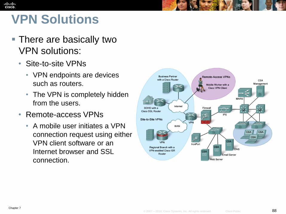
VPN Solutions
There are basically two
VPN solutions:
• Site-to-site VPNs
• VPN endpoints are devices
such as routers.
• The VPN is completely hidden
from the users.
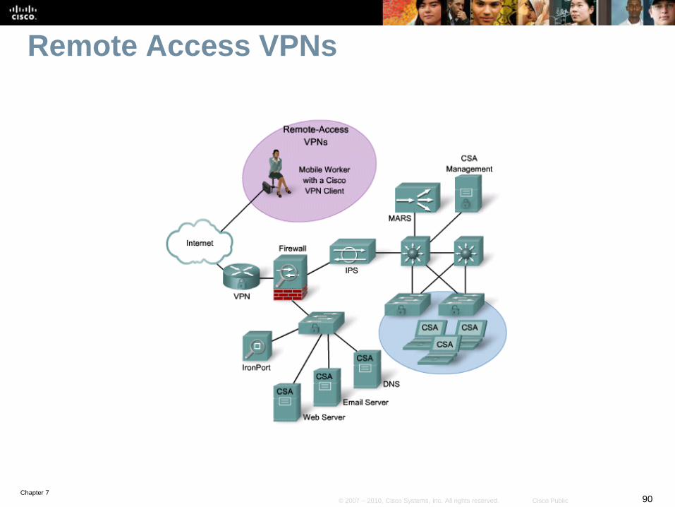
• Remote-access VPNs
• A mobile user initiates a VPN
connection request using either
VPN client software or an
Internet browser and SSL
connection.

Chapter 789© 2007 – 2010, Cisco Systems, Inc. All rights reserved. Cisco Public
Site-to-Site VPNs
Chapter 790© 2007 – 2010, Cisco Systems, Inc. All rights reserved. Cisco Public
Remote Access VPNs

Chapter 791© 2007 – 2010, Cisco Systems, Inc. All rights reserved. Cisco Public
IPsec Technologies
IPsec VPNs provide two significant benefits:
• Encryption
• Encapsulation
IPsec encryption provides three major services:
• Confidentiality
• Integrity
• Authentication
Chapter 792© 2007 – 2010, Cisco Systems, Inc. All rights reserved. Cisco Public
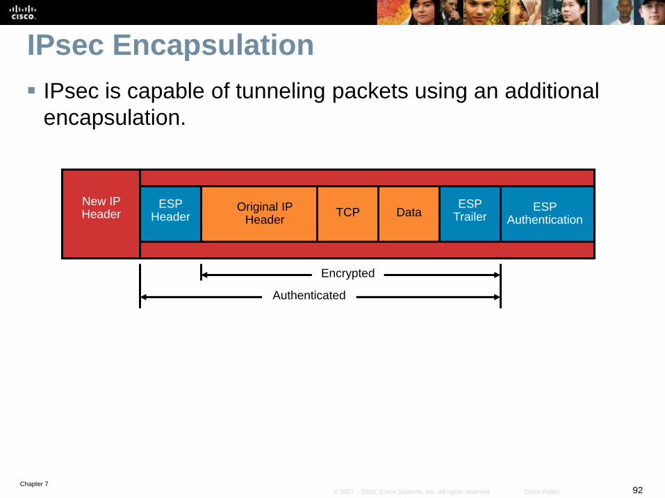
IPsec Encapsulation
IPsec is capable of tunneling packets using an additional
encapsulation.
ESP Header
ESP Trailer
ESP Authentication
New IP Header
Original IP Header
TCP Data
Authenticated
Encrypted

Chapter 793© 2007 – 2010, Cisco Systems, Inc. All rights reserved. Cisco Public
IPsec Encapsulation Example
The example displays how a packet is encapsulated.
Branch HQ
Internet
192.168.1.0 /24 10.10.10.0 /24
S0/0/1Fa0/0
.242
.1 .1
Fa0/0
209.165.200.240 /29
.241
S0/0/1
209.165.200.224 /29
.226
.225
ISP
.10.10
Original IP Header
Source IP: 192.168.1.10
Destination: 10.10.10.10
TCP Data
Original IP Header
Source IP: 192.168.1.10
Destination: 10.10.10.10
TCP Data
IPsec VPN
New IP Header
Source: 209.165.200.242
Destination: 209.165.200.226
ESP
Header
Original IP Header
Source IP: 192.168.1.10
Destination: 10.10.10.10
TCP DataESP
Trailer
ESP
Authentication

Chapter 794© 2007 – 2010, Cisco Systems, Inc. All rights reserved. Cisco Public
IPsec Site-to-Site VPN Example
The Branch router has been configured to support an IPsec VPN when
connecting to the HQ site.
The purpose of the IPsec VPN link is to serve as a backup link in case
the private WAN link fails.
• The long-term goal is to decommission the WAN link completely and use only the VPN
connection to communicate between the branch office and the headquarters.
Internet
Branch HQ
192.168.1.0 /24 10.10.10.0 /24
S0/0/1Fa0/0
.242
.1 .1
Fa0/0
209.165.200.224 /29
.241
S0/0/1
209.165.200.240 /29
.225
.226
ISP
Email Server10.10.10.238
(209.165.200.238)
NAT Pool209.165.200.233 –
209.165.200.237 /29
Branch Server192.168.1.254
(209.165.200.254)
NAT Pool209.165.200.249 –209.165.200.253/29
IPsec VPN
Chapter 795© 2007 – 2010, Cisco Systems, Inc. All rights reserved. Cisco Public
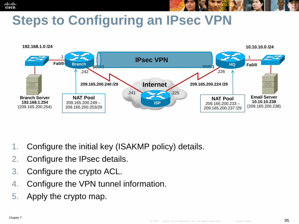
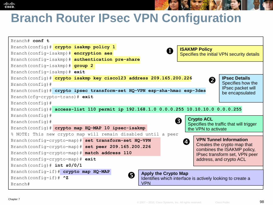
Steps to Configuring an IPsec VPN
1. Configure the initial key (ISAKMP policy) details.
2. Configure the IPsec details.
3. Configure the crypto ACL.
4. Configure the VPN tunnel information.
5. Apply the crypto map.
Internet
Branch HQ
192.168.1.0 /24 10.10.10.0 /24
S0/0/1Fa0/0
.242
.1 .1
Fa0/0
209.165.200.224 /29
.241
S0/0/1
209.165.200.240 /29
.225
.226
ISP
Email Server10.10.10.238
(209.165.200.238)
NAT Pool209.165.200.233 –
209.165.200.237 /29
Branch Server192.168.1.254
(209.165.200.254)
NAT Pool209.165.200.249 –209.165.200.253/29
IPsec VPN
Chapter 796© 2007 – 2010, Cisco Systems, Inc. All rights reserved. Cisco Public
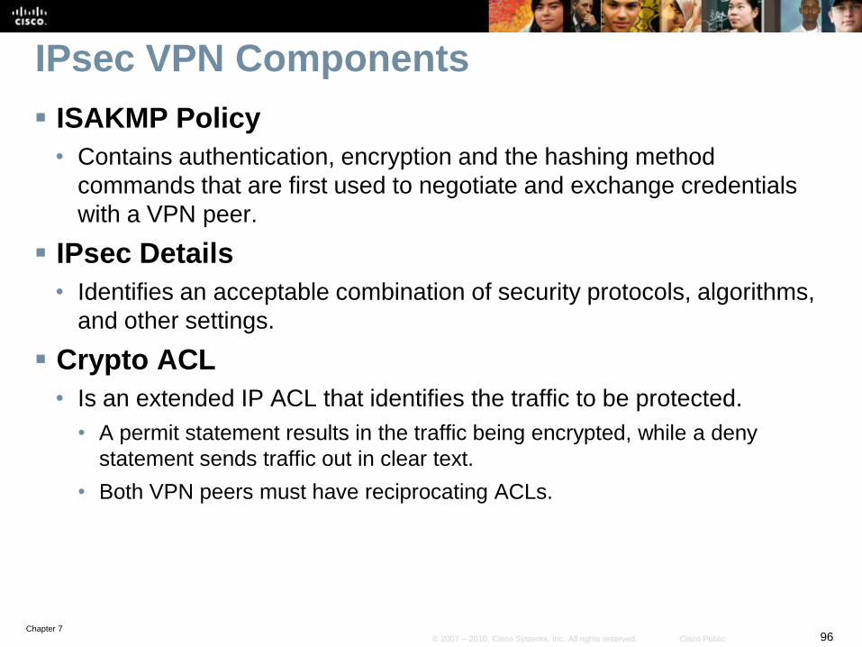
IPsec VPN Components
ISAKMP Policy
• Contains authentication, encryption and the hashing method
commands that are first used to negotiate and exchange credentials
with a VPN peer.
IPsec Details
• Identifies an acceptable combination of security protocols, algorithms,
and other settings.
Crypto ACL
• Is an extended IP ACL that identifies the traffic to be protected.
• A permit statement results in the traffic being encrypted, while a deny
statement sends traffic out in clear text.
• Both VPN peers must have reciprocating ACLs.
Chapter 797© 2007 – 2010, Cisco Systems, Inc. All rights reserved. Cisco Public
IPsec VPN Components
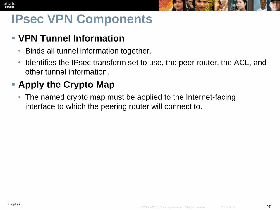
VPN Tunnel Information
• Binds all tunnel information together.
• Identifies the IPsec transform set to use, the peer router, the ACL, and
other tunnel information.
Apply the Crypto Map
• The named crypto map must be applied to the Internet-facing
interface to which the peering router will connect to.
Chapter 798© 2007 – 2010, Cisco Systems, Inc. All rights reserved. Cisco Public
Branch Router IPsec VPN Configuration
Branch# conf t
Branch(config)# crypto isakmp policy 1
Branch(config-isakmp)# encryption aes
Branch(config-isakmp)# authentication pre-share
Branch(config-isakmp)# group 2
Branch(config-isakmp)# exit
Branch(config)# crypto isakmp key cisco123 address 209.165.200.226
Branch(config)#
Branch(config)# crypto ipsec transform-set HQ-VPN esp-sha-hmac esp-3des
Branch(cfg-crypto-trans)# exit
Branch(config)#
Branch(config)# access-list 110 permit ip 192.168.1.0 0.0.0.255 10.10.10.0 0.0.0.255
Branch(config)#
Branch(config)#
Branch(config)# crypto map HQ-MAP 10 ipsec-isakmp
% NOTE: This new crypto map will remain disabled until a peer
Branch(config-crypto-map)# set transform-set HQ-VPN
Branch(config-crypto-map)# set peer 209.165.200.226
Branch(config-crypto-map)# match address 110
Branch(config-crypto-map)# exit
Branch(config)# int s0/0/1
Branch(config-if)# crypto map HQ-MAP
Branch(config-if)# ^Z
Branch#
ISAKMP PolicySpecifies the initial VPN security details
IPsec DetailsSpecifies how the IPsec packet will be encapsulated
VPN Tunnel InformationCreates the crypto map that combines the ISAKMP policy, IPsec transform set, VPN peer address, and crypto ACL
Crypto ACLSpecifies the traffic that will trigger the VPN to activate
Apply the Crypto MapIdentifies which interface is actively looking to create a VPN
Chapter 799© 2007 – 2010, Cisco Systems, Inc. All rights reserved. Cisco Public
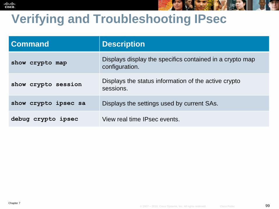
Verifying and Troubleshooting IPsec
Command Description
show crypto mapDisplays display the specifics contained in a crypto map
configuration.
show crypto sessionDisplays the status information of the active crypto
sessions.
show crypto ipsec sa Displays the settings used by current SAs.
debug crypto ipsec View real time IPsec events.

Chapter 7100© 2007 – 2010, Cisco Systems, Inc. All rights reserved. Cisco Public
IPsec VPN Verification Example
Enable IPsec debugging and generate interesting VPN traffic.
Notice that the ping traffic matches the crypto ACL 110 however, no debug output is generated.• access-list 110 permit ip 192.168.1.0 0.0.0.255 10.10.10.0 0.0.0.255
Internet
Branch HQ
192.168.1.0 /24 10.10.10.0 /24
S0/0/1Fa0/0
.242
.1 .1
Fa0/0
209.165.200.224 /29
.241
S0/0/1
209.165.200.240 /29
.225
.226
ISP
Email Server10.10.10.238
(209.165.200.238)
NAT Pool209.165.200.233 –
209.165.200.237 /29
Branch Server192.168.1.254
(209.165.200.254)
NAT Pool209.165.200.249 –209.165.200.253/29
IPsec VPN
Branch# debug crypto ipsec
Crypto IPSEC debugging is on
Branch# ping 10.10.10.1 source 192.168.1.1
Type escape sequence to abort.
Sending 5, 100-byte ICMP Echos to 10.10.10.1, timeout is 2 seconds:
Packet sent with a source address of 192.168.1.1
!!!!!
Success rate is 100 percent (5/5), round-trip min/avg/max = 56/56/60 ms
Branch#
Chapter 7101© 2007 – 2010, Cisco Systems, Inc. All rights reserved. Cisco Public
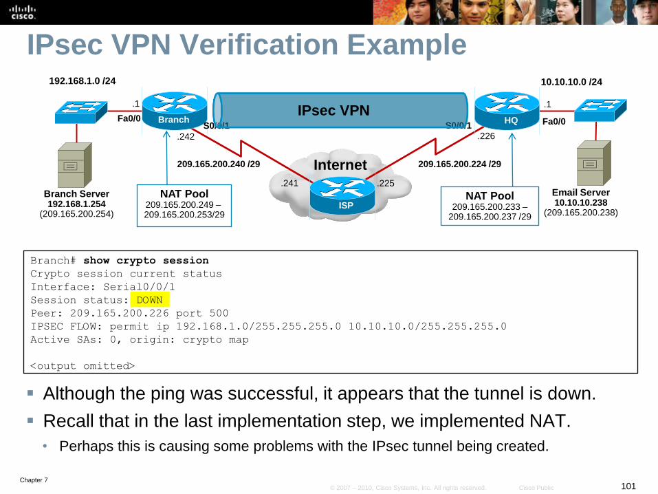
IPsec VPN Verification Example
Although the ping was successful, it appears that the tunnel is down.
Recall that in the last implementation step, we implemented NAT.
• Perhaps this is causing some problems with the IPsec tunnel being created.
Internet
Branch HQ
192.168.1.0 /24 10.10.10.0 /24
S0/0/1Fa0/0
.242
.1 .1
Fa0/0
209.165.200.224 /29
.241
S0/0/1
209.165.200.240 /29
.225
.226
ISP
Email Server10.10.10.238
(209.165.200.238)
NAT Pool209.165.200.233 –
209.165.200.237 /29
Branch Server192.168.1.254
(209.165.200.254)
NAT Pool209.165.200.249 –209.165.200.253/29
IPsec VPN
Branch# show crypto session
Crypto session current status
Interface: Serial0/0/1
Session status: DOWN
Peer: 209.165.200.226 port 500
IPSEC FLOW: permit ip 192.168.1.0/255.255.255.0 10.10.10.0/255.255.255.0
Active SAs: 0, origin: crypto map
<output omitted>

Chapter 7102© 2007 – 2010, Cisco Systems, Inc. All rights reserved. Cisco Public
IPsec VPN Verification Example
Enable NAT debugging and ping again.
The pings are again successful.
Branch# debug ip nat
IP NAT debugging is on
Branch# ping 10.10.10.1 source 192.168.1.1
Type escape sequence to abort.
Sending 5, 100-byte ICMP Echos to 10.10.10.1, timeout is 2 seconds:
Packet sent with a source address of 192.168.1.1
!!!!!
Success rate is 100 percent (5/5), round-trip min/avg/max = 56/57/60 ms
Branch#
Internet
Branch HQ
192.168.1.0 /24 10.10.10.0 /24
S0/0/1Fa0/0
.242
.1 .1
Fa0/0
209.165.200.224 /29
.241
S0/0/1
209.165.200.240 /29
.225
.226
ISP
Email Server10.10.10.238
(209.165.200.238)
NAT Pool209.165.200.233 –
209.165.200.237 /29
Branch Server192.168.1.254
(209.165.200.254)
NAT Pool209.165.200.249 –209.165.200.253/29
IPsec VPN
Chapter 7103© 2007 – 2010, Cisco Systems, Inc. All rights reserved. Cisco Public
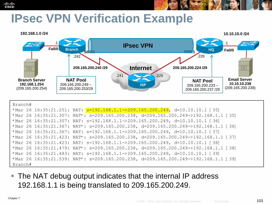
IPsec VPN Verification Example
The NAT debug output indicates that the internal IP address
192.168.1.1 is being translated to 209.165.200.249.
Branch#
*Mar 26 16:35:21.251: NAT: s=192.168.1.1->209.165.200.249, d=10.10.10.1 [35]
*Mar 26 16:35:21.307: NAT*: s=209.165.200.238, d=209.165.200.249->192.168.1.1 [35]
*Mar 26 16:35:21.307: NAT: s=192.168.1.1->209.165.200.249, d=10.10.10.1 [36]
*Mar 26 16:35:21.367: NAT*: s=209.165.200.238, d=209.165.200.249->192.168.1.1 [36]
*Mar 26 16:35:21.367: NAT: s=192.168.1.1->209.165.200.249, d=10.10.10.1 [37]
*Mar 26 16:35:21.423: NAT*: s=209.165.200.238, d=209.165.200.249->192.168.1.1 [37]
*Mar 26 16:35:21.423: NAT: s=192.168.1.1->209.165.200.249, d=10.10.10.1 [38]
*Mar 26 16:35:21.479: NAT*: s=209.165.200.238, d=209.165.200.249->192.168.1.1 [38]
*Mar 26 16:35:21.483: NAT: s=192.168.1.1->209.165.200.249, d=10.10.10.1 [39]
*Mar 26 16:35:21.539: NAT*: s=209.165.200.238, d=209.165.200.249->192.168.1.1 [39]
Branch#
Internet
Branch HQ
192.168.1.0 /24 10.10.10.0 /24
S0/0/1Fa0/0
.242
.1 .1
Fa0/0
209.165.200.224 /29
.241
S0/0/1
209.165.200.240 /29
.225
.226
ISP
Email Server10.10.10.238
(209.165.200.238)
NAT Pool209.165.200.233 –
209.165.200.237 /29
Branch Server192.168.1.254
(209.165.200.254)
NAT Pool209.165.200.249 –209.165.200.253/29
IPsec VPN

Chapter 7104© 2007 – 2010, Cisco Systems, Inc. All rights reserved. Cisco Public
IPsec VPN Verification Example
BRANCH-NAT-ACL identifies traffic to translate and has one match.
• ACL 110 is for the IPsec VPN.
What is the solution to this problem?
Branch# show access-lists
Extended IP access list 110
10 permit ip 192.168.1.0 0.0.0.255 10.10.10.0 0.0.0.255
Extended IP access list BRANCH-NAT-ACL
10 permit ip 192.168.1.0 0.0.0.255 any (1 match)
Branch#
Internet
Branch HQ
192.168.1.0 /24 10.10.10.0 /24
S0/0/1Fa0/0
.242
.1 .1
Fa0/0
209.165.200.224 /29
.241
S0/0/1
209.165.200.240 /29
.225
.226
ISP
Email Server10.10.10.238
(209.165.200.238)
NAT Pool209.165.200.233 –
209.165.200.237 /29
Branch Server192.168.1.254
(209.165.200.254)
NAT Pool209.165.200.249 –209.165.200.253/29
IPsec VPN

Chapter 7105© 2007 – 2010, Cisco Systems, Inc. All rights reserved. Cisco Public
IPsec VPN Verification Example
Alter the NAT ACL to exempt VPN traffic.
• The ACL should ignore the Branch LAN traffic going to the HQ LAN!
Branch(config)# no ip access-list extended BRANCH-NAT-ACL
Branch(config)# ip access-list extended BRANCH-NAT-ACL
Branch(config-ext-nacl)# deny ip 192.168.1.0 0.0.0.255 10.10.10.0 0.0.0.255
Branch(config-ext-nacl)# permit ip 192.168.1.0 0.0.0.255 any
Branch(config-ext-nacl)# ^Z
Branch
Internet
Branch HQ
192.168.1.0 /24 10.10.10.0 /24
S0/0/1Fa0/0
.242
.1 .1
Fa0/0
209.165.200.224 /29
.241
S0/0/1
209.165.200.240 /29
.225
.226
ISP
Email Server10.10.10.238
(209.165.200.238)
NAT Pool209.165.200.233 –
209.165.200.237 /29
Branch Server192.168.1.254
(209.165.200.254)
NAT Pool209.165.200.249 –209.165.200.253/29
IPsec VPN

Chapter 7106© 2007 – 2010, Cisco Systems, Inc. All rights reserved. Cisco Public
IPsec VPN Verification Example
Clear the NAT translations and IPsec SAs and generate interesting VPN
traffic.
Branch# clear ip nat translation *
Branch# clear crypto isakmp
Branch# clear crypto sa
Branch# ping 10.10.10.1 source 192.168.1.1
Type escape sequence to abort.
Sending 5, 100-byte ICMP Echos to 10.10.10.1, timeout is 2 seconds:
Packet sent with a source address of 192.168.1.1
!!!!!
Success rate is 100 percent (5/5), round-trip min/avg/max = 56/57/60 ms
Branch#
Internet
Branch HQ
192.168.1.0 /24 10.10.10.0 /24
S0/0/1Fa0/0
.242
.1 .1
Fa0/0
209.165.200.224 /29
.241
S0/0/1
209.165.200.240 /29
.225
.226
ISP
Email Server10.10.10.238
(209.165.200.238)
NAT Pool209.165.200.233 –
209.165.200.237 /29
Branch Server192.168.1.254
(209.165.200.254)
NAT Pool209.165.200.249 –209.165.200.253/29
IPsec VPN
Chapter 7107© 2007 – 2010, Cisco Systems, Inc. All rights reserved. Cisco Public
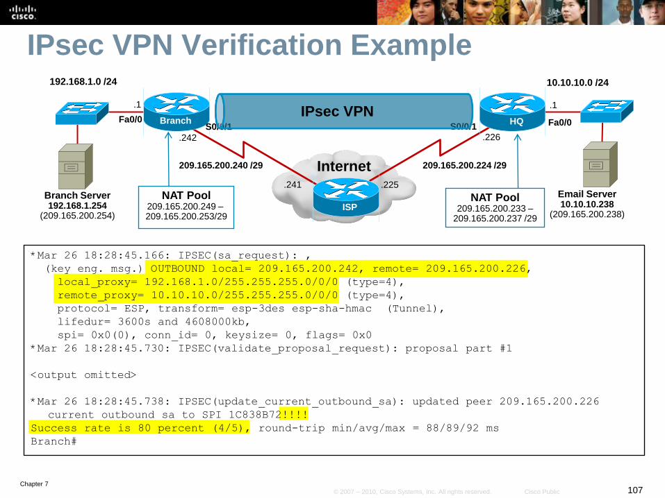
IPsec VPN Verification Example
*Mar 26 18:28:45.166: IPSEC(sa_request): ,
(key eng. msg.) OUTBOUND local= 209.165.200.242, remote= 209.165.200.226,
local_proxy= 192.168.1.0/255.255.255.0/0/0 (type=4),
remote_proxy= 10.10.10.0/255.255.255.0/0/0 (type=4),
protocol= ESP, transform= esp-3des esp-sha-hmac (Tunnel),
lifedur= 3600s and 4608000kb,
spi= 0x0(0), conn_id= 0, keysize= 0, flags= 0x0
*Mar 26 18:28:45.730: IPSEC(validate_proposal_request): proposal part #1
<output omitted>
*Mar 26 18:28:45.738: IPSEC(update_current_outbound_sa): updated peer 209.165.200.226
current outbound sa to SPI 1C838B72!!!!
Success rate is 80 percent (4/5), round-trip min/avg/max = 88/89/92 ms
Branch#
Internet
Branch HQ
192.168.1.0 /24 10.10.10.0 /24
S0/0/1Fa0/0
.242
.1 .1
Fa0/0
209.165.200.224 /29
.241
S0/0/1
209.165.200.240 /29
.225
.226
ISP
Email Server10.10.10.238
(209.165.200.238)
NAT Pool209.165.200.233 –
209.165.200.237 /29
Branch Server192.168.1.254
(209.165.200.254)
NAT Pool209.165.200.249 –209.165.200.253/29
IPsec VPN
Chapter 7108© 2007 – 2010, Cisco Systems, Inc. All rights reserved. Cisco Public
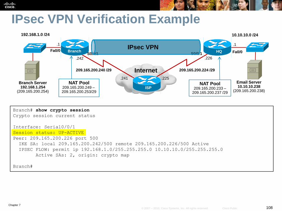
IPsec VPN Verification Example
Branch# show crypto session
Crypto session current status
Interface: Serial0/0/1
Session status: UP-ACTIVE
Peer: 209.165.200.226 port 500
IKE SA: local 209.165.200.242/500 remote 209.165.200.226/500 Active
IPSEC FLOW: permit ip 192.168.1.0/255.255.255.0 10.10.10.0/255.255.255.0
Active SAs: 2, origin: crypto map
Branch#
Internet
Branch HQ
192.168.1.0 /24 10.10.10.0 /24
S0/0/1Fa0/0
.242
.1 .1
Fa0/0
209.165.200.224 /29
.241
S0/0/1
209.165.200.240 /29
.225
.226
ISP
Email Server10.10.10.238
(209.165.200.238)
NAT Pool209.165.200.233 –
209.165.200.237 /29
Branch Server192.168.1.254
(209.165.200.254)
NAT Pool209.165.200.249 –209.165.200.253/29
IPsec VPN

Chapter 7109© 2007 – 2010, Cisco Systems, Inc. All rights reserved. Cisco Public
IPsec VPN Verification Example
Branch# show crypto ipsec sa
interface: Serial0/0/1
Crypto map tag: HQ-MAP, local addr 209.165.200.242
protected vrf: (none)
local ident (addr/mask/prot/port): (192.168.1.0/255.255.255.0/0/0)
remote ident (addr/mask/prot/port): (10.10.10.0/255.255.255.0/0/0)
current_peer 209.165.200.226 port 500
PERMIT, flags={origin_is_acl,}
#pkts encaps: 4, #pkts encrypt: 4, #pkts digest: 4
#pkts decaps: 4, #pkts decrypt: 4, #pkts verify: 4
#pkts compressed: 0, #pkts decompressed: 0
#pkts not compressed: 0, #pkts compr. failed: 0
<output omitted>
Internet
Branch HQ
192.168.1.0 /24 10.10.10.0 /24
S0/0/1Fa0/0
.242
.1 .1
Fa0/0
209.165.200.224 /29
.241
S0/0/1
209.165.200.240 /29
.225
.226
ISP
Email Server10.10.10.238
(209.165.200.238)
NAT Pool209.165.200.233 –
209.165.200.237 /29
Branch Server192.168.1.254
(209.165.200.254)
NAT Pool209.165.200.249 –209.165.200.253/29
IPsec VPN

Chapter 7110© 2007 – 2010, Cisco Systems, Inc. All rights reserved. Cisco Public
IPsec VPN Verification Example
The example confirmed that the Branch router and HQ router have an
established VPN.
Notice how a service such as NAT could impact the creation of the VPN
tunnel.
Internet
Branch HQ
192.168.1.0 /24 10.10.10.0 /24
S0/0/1Fa0/0
.242
.1 .1
Fa0/0
209.165.200.224 /29
.241
S0/0/1
209.165.200.240 /29
.225
.226
ISP
Email Server10.10.10.238
(209.165.200.238)
NAT Pool209.165.200.233 –
209.165.200.237 /29
Branch Server192.168.1.254
(209.165.200.254)
NAT Pool209.165.200.249 –209.165.200.253/29
IPsec VPN

Chapter 7111© 2007 – 2010, Cisco Systems, Inc. All rights reserved. Cisco Public
IPsec VPN Verification Example
Currently the VPN link is only enabled due to static routing.
What would happen if EIGRP was configured to operate
over the link?
• Would it work?
Internet
Branch HQ
192.168.1.0 /24 10.10.10.0 /24
S0/0/1Fa0/0
.242
.1 .1
Fa0/0
209.165.200.224 /29
.241
S0/0/1
209.165.200.240 /29
.225
.226
ISP
Email Server10.10.10.238
(209.165.200.238)
NAT Pool209.165.200.233 –
209.165.200.237 /29
Branch Server192.168.1.254
(209.165.200.254)
NAT Pool209.165.200.249 –209.165.200.253/29
IPsec VPN

Chapter 7112© 2007 – 2010, Cisco Systems, Inc. All rights reserved. Cisco Public
IPsec VPN Verification Example
A significant drawback of an IPsec VPN is that it cannot route multicast
and broadcast packets and therefore cannot support IGPs.
However, IPsec can be combined with generic routing encapsulation
(GRE) to create a tunnel to circumvent the issue.
Internet
Branch HQ
192.168.1.0 /24 10.10.10.0 /24
S0/0/1Fa0/0
.242
.1 .1
Fa0/0
209.165.200.224 /29
.241
S0/0/1
209.165.200.240 /29
.225
.226
ISP
Email Server10.10.10.238
(209.165.200.238)
NAT Pool209.165.200.233 –
209.165.200.237 /29
Branch Server192.168.1.254
(209.165.200.254)
NAT Pool209.165.200.249 –209.165.200.253/29
IPsec VPN

Chapter 7113© 2007 – 2010, Cisco Systems, Inc. All rights reserved. Cisco Public
Implementation Plan
1. Deploy broadband connectivity
2. Configure static routing
3. Document and verify other services
4. Implement and tune the IPsec VPN
5. Configure GRE tunnels

Chapter 7114© 2007 – 2010, Cisco Systems, Inc. All rights reserved. Cisco Public
Routing IGPs Using IPsec
Point-to-point generic routing encapsulation (P2P GRE)
• IGPs are associated with tunnel interfaces which use the physical
interface of the router to send GRE traffic.
• GRE traffic will have to be added to the crypto ACL.
Virtual tunnel interface (VTI)
• IPsec endpoints are associated with routable virtual interfaces at the
tunnel endpoints.
• VTI is a good alternative to IPsec over GRE tunnels.
Dynamic multipoint VPN (DMVPN) or Group encrypted
transport VPN (GET VPN)
• Both designed for large scale full mesh IPsec VPN implementations.

Chapter 7115© 2007 – 2010, Cisco Systems, Inc. All rights reserved. Cisco Public
GRE Overview
Tunneling protocol developed by Cisco.
Can encapsulate a wide variety of network layer protocol
packets inside IP tunnels.
• GRE is commonly implemented with IPsec to support IGPs.
GRE is just an encapsulation protocol.
• By default, the traffic leaves in clear text.
Therefore , GRE tunnels do not provide encryption services.
• IPsec must also be configured to encrypt the routing traffic.
Note:
• IPsec was designed to tunnel IP only (no multiprotocol support)
• Older IOS versions do not support IP multicast over IPsec

Chapter 7116© 2007 – 2010, Cisco Systems, Inc. All rights reserved. Cisco Public
Sending IGP Traffic Over IPsec
Routing protocols are encapsulated with a GRE header.
The packet encapsulated by GRE is then encapsulated with
IPsec.
Therefore, IPsec encrypts the GRE packet which contains
the routing update.
IPsecCryptoMap
GRE Tunnel IPsec Encrypted TrafficRouting Protocol Updates
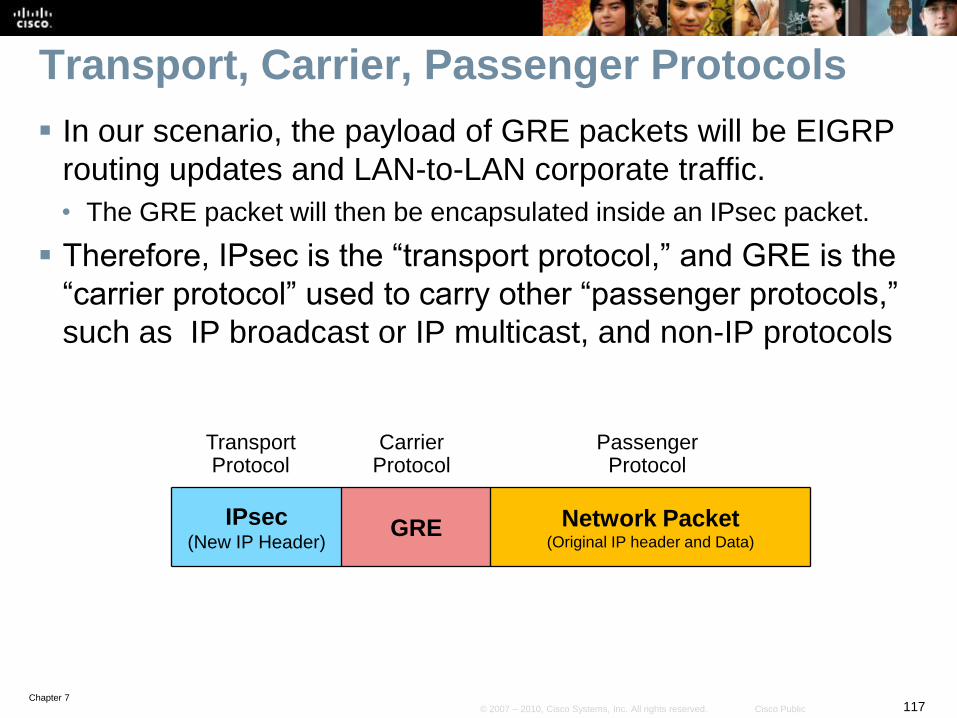
Chapter 7117© 2007 – 2010, Cisco Systems, Inc. All rights reserved. Cisco Public
Transport, Carrier, Passenger Protocols
In our scenario, the payload of GRE packets will be EIGRP
routing updates and LAN-to-LAN corporate traffic.
• The GRE packet will then be encapsulated inside an IPsec packet.
Therefore, IPsec is the “transport protocol,” and GRE is the
“carrier protocol” used to carry other “passenger protocols,”
such as IP broadcast or IP multicast, and non-IP protocols
IPsec(New IP Header)
GRE Network Packet(Original IP header and Data)
Transport Protocol
CarrierProtocol
PassengerProtocol
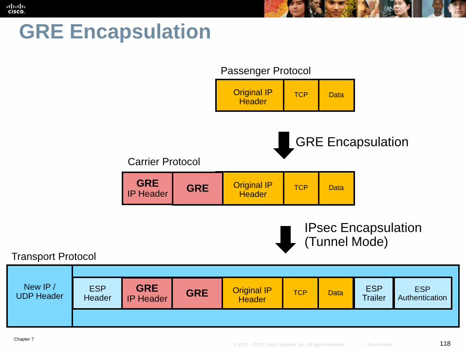
Chapter 7118© 2007 – 2010, Cisco Systems, Inc. All rights reserved. Cisco Public
GRE Encapsulation
GRE Encapsulation
IPsec Encapsulation(Tunnel Mode)
ESP Header
ESP Trailer
ESP Authentication
New IP / UDP Header
Original IP Header
TCP Data
Original IP Header
TCP DataGRE
Original IP Header
TCP DataGRE
Transport Protocol
Carrier Protocol
Passenger Protocol
GREGRE
IP Header
GREGRE
IP Header

Chapter 7119© 2007 – 2010, Cisco Systems, Inc. All rights reserved. Cisco Public
Steps to Configuring GRE
1. Create a tunnel interface for GRE.
2. Configure GRE tunnel parameters including IP address, source and
destination tunnel addresses, and tunnel mode.
3. Change the crypto ACL to encrypt GRE traffic.
4. Configure routing protocols to route through the GRE tunnel.
Internet
Branch HQ
192.168.1.0 /24 10.10.10.0 /24
S0/0/1Fa0/0
.242
.1 .1
Fa0/0
209.165.200.224 /29
.241
S0/0/1
209.165.200.240 /29
.225
.226
ISP
Email Server10.10.10.238
(209.165.200.238)
NAT Pool209.165.200.233 –
209.165.200.237 /29
Branch Server192.168.1.254
(209.165.200.254)
NAT Pool209.165.200.249 –209.165.200.253/29
172.16.100.2 172.16.100.0.1GRE Tunnel
172.16.100.0/30
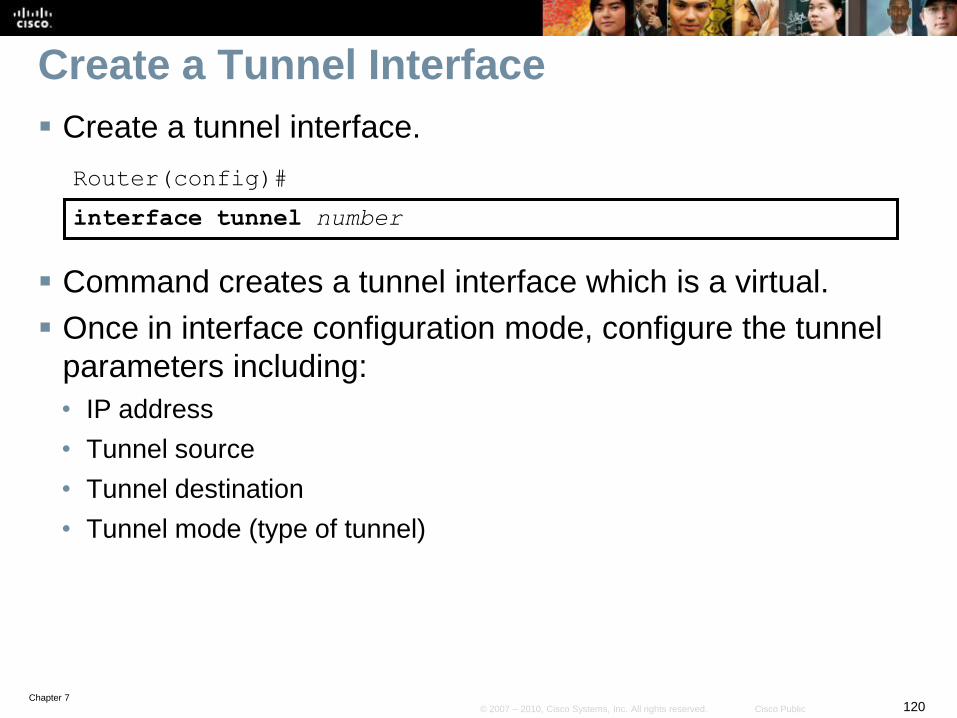
Chapter 7120© 2007 – 2010, Cisco Systems, Inc. All rights reserved. Cisco Public
Create a Tunnel Interface
Create a tunnel interface.
Router(config)#
interface tunnel number
Command creates a tunnel interface which is a virtual.
Once in interface configuration mode, configure the tunnel
parameters including:
• IP address
• Tunnel source
• Tunnel destination
• Tunnel mode (type of tunnel)
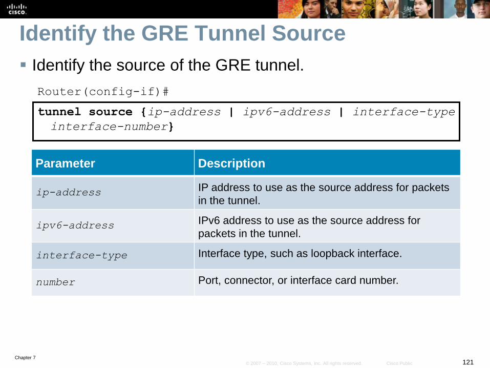
Chapter 7121© 2007 – 2010, Cisco Systems, Inc. All rights reserved. Cisco Public
Identify the GRE Tunnel Source
Identify the source of the GRE tunnel.
Router(config-if)#
tunnel source {ip-address | ipv6-address | interface-type
interface-number}
Parameter Description
ip-address IP address to use as the source address for packets
in the tunnel.
ipv6-address IPv6 address to use as the source address for
packets in the tunnel.
interface-type Interface type, such as loopback interface.
number Port, connector, or interface card number.
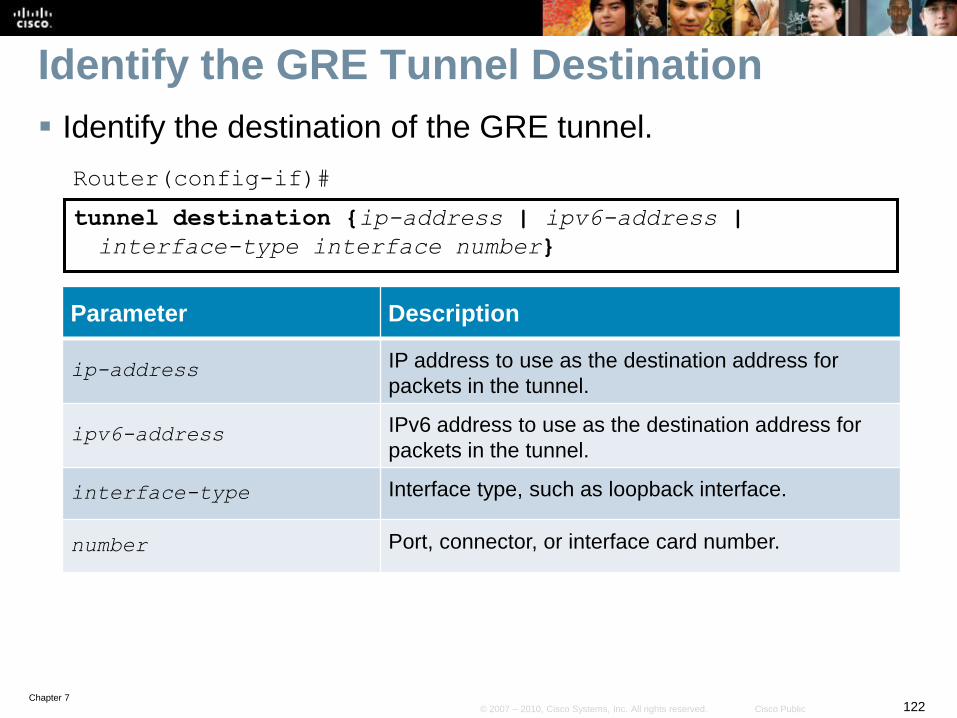
Chapter 7122© 2007 – 2010, Cisco Systems, Inc. All rights reserved. Cisco Public
Identify the GRE Tunnel Destination
Identify the destination of the GRE tunnel.
Router(config-if)#
tunnel destination {ip-address | ipv6-address |
interface-type interface number}
Parameter Description
ip-address IP address to use as the destination address for
packets in the tunnel.
ipv6-address IPv6 address to use as the destination address for
packets in the tunnel.
interface-type Interface type, such as loopback interface.
number Port, connector, or interface card number.

Chapter 7123© 2007 – 2010, Cisco Systems, Inc. All rights reserved. Cisco Public
Identify the Tunnel Mode
Set the encapsulation mode for the tunnel interface.
Router(config-if)#
tunnel mode {aurp | cayman | dvmrp | eon | gre ip | gre
multipoint | gre ipv6 | ipip [decapsulate-any] | ipsec
ipv4 | iptalk | ipv6 | ipsec ipv6 | mpls | nos | rbscp}
Optional command since the default tunnel mode is tunnel mode gre ip
Of interest to us is specifically the tunnel mode gre
option.
• The additional options listed are for reference only.

Chapter 7124© 2007 – 2010, Cisco Systems, Inc. All rights reserved. Cisco Public
Configuring GRE Example
Configure the tunnel interface on the Branch router.
Branch(config)# interface tunnel 0
Branch(config-if)# ip address 172.16.100.2 255.255.255.252
Branch(config-if)# tunnel source 209.165.200.242
Branch(config-if)# tunnel destination 209.165.200.226
Branch(config-if)#
*Mar 27 15:45:05.647: %LINEPROTO-5-UPDOWN: Line protocol on Interface Tunnel0,
changed state to up
Branch(config-if)#
Internet
Branch HQ
192.168.1.0 /24 10.10.10.0 /24
S0/0/1Fa0/0
.242
.1 .1
Fa0/0
209.165.200.224 /29
.241
S0/0/1
209.165.200.240 /29
.225
.226
ISP
Email Server10.10.10.238
(209.165.200.238)
NAT Pool209.165.200.233 –
209.165.200.237 /29
Branch Server192.168.1.254
(209.165.200.254)
NAT Pool209.165.200.249 –209.165.200.253/29
172.16.100.2 172.16.100.0.1GRE Tunnel
172.16.100.0/30
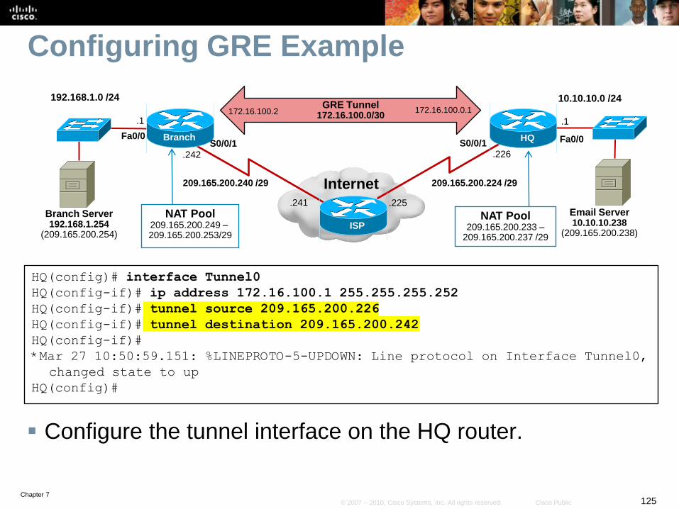
Chapter 7125© 2007 – 2010, Cisco Systems, Inc. All rights reserved. Cisco Public
Configuring GRE Example
Configure the tunnel interface on the HQ router.
HQ(config)# interface Tunnel0
HQ(config-if)# ip address 172.16.100.1 255.255.255.252
HQ(config-if)# tunnel source 209.165.200.226
HQ(config-if)# tunnel destination 209.165.200.242
HQ(config-if)#
*Mar 27 10:50:59.151: %LINEPROTO-5-UPDOWN: Line protocol on Interface Tunnel0,
changed state to up
HQ(config)#
Internet
Branch HQ
192.168.1.0 /24 10.10.10.0 /24
S0/0/1Fa0/0
.242
.1 .1
Fa0/0
209.165.200.224 /29
.241
S0/0/1
209.165.200.240 /29
.225
.226
ISP
Email Server10.10.10.238
(209.165.200.238)
NAT Pool209.165.200.233 –
209.165.200.237 /29
Branch Server192.168.1.254
(209.165.200.254)
NAT Pool209.165.200.249 –209.165.200.253/29
172.16.100.2 172.16.100.0.1GRE Tunnel
172.16.100.0/30

Chapter 7126© 2007 – 2010, Cisco Systems, Inc. All rights reserved. Cisco Public
Verify the Tunnel Configuration
Branch# show interfaces tunnel 0
Tunnel0 is up, line protocol is up
Hardware is Tunnel
Internet address is 172.16.100.2/30
MTU 17916 bytes, BW 100 Kbit/sec, DLY 50000 usec,
reliability 255/255, txload 1/255, rxload 1/255
Encapsulation TUNNEL, loopback not set
Keepalive not set
Tunnel source 209.165.200.242, destination 209.165.200.226
Tunnel protocol/transport GRE/IP
Key disabled, sequencing disabled
Checksumming of packets disabled
Tunnel TTL 255
Fast tunneling enabled
Tunnel transport MTU 1476 bytes
Tunnel transmit bandwidth 8000 (kbps)
Tunnel receive bandwidth 8000 (kbps)
Last input never, output never, output hang never
Last clearing of "show interface" counters never
Input queue: 0/75/0/0 (size/max/drops/flushes); Total output drops: 0
Queueing strategy: fifo
Output queue: 0/0 (size/max)
5 minute input rate 0 bits/sec, 0 packets/sec
5 minute output rate 0 bits/sec, 0 packets/sec
<output omitted>

Chapter 7127© 2007 – 2010, Cisco Systems, Inc. All rights reserved. Cisco Public
Configuring GRE Example
Change the ACL and add the Internet link and GRE tunnel
network to EIGRP on the Branch router.
Branch(config)# no access-list 110
Branch(config)# access-list 110 permit gre host 209.165.200.242 host
209.165.200.226
Branch(config)# router eigrp 1
Branch(config-router)# network 192.168.1.0 0.0.0.255
Branch(config-router)# network 172.16.100.0 0.0.0.3
Branch(config-router)# no auto-summary
Branch(config-router)#
Internet
Branch HQ
192.168.1.0 /24 10.10.10.0 /24
S0/0/1Fa0/0
.242
.1 .1
Fa0/0
209.165.200.224 /29
.241
S0/0/1
209.165.200.240 /29
.225
.226
ISP
Email Server10.10.10.238
(209.165.200.238)
NAT Pool209.165.200.233 –
209.165.200.237 /29
Branch Server192.168.1.254
(209.165.200.254)
NAT Pool209.165.200.249 –209.165.200.253/29
172.16.100.2 172.16.100.1GRE Tunnel
172.16.100.0/30

Chapter 7128© 2007 – 2010, Cisco Systems, Inc. All rights reserved. Cisco Public
Configuring GRE Example
Do the same on the HQ router.
HQ(config)# no access-list 110
HQ(config)# access-list 110 permit gre host 209.165.200.226 host
209.165.200.242
HQ(config)# router eigrp 1
HQ(config-router)# network 10.10.10.0 0.0.0.255
HQ(config-router)# network 172.16.100.0 0.0.0.3
HQ(config-router)# no auto-summary
HQ(config-router)#
*Mar 27 12:02:52.483: %DUAL-5-NBRCHANGE: IP-EIGRP(0) 1: Neighbor 172.16.100.2
(Tunnel0) is up: new adjacency
HQ(config-router)#
Internet
Branch HQ
192.168.1.0 /24 10.10.10.0 /24
S0/0/1Fa0/0
.242
.1 .1
Fa0/0
209.165.200.224 /29
.241
S0/0/1
209.165.200.240 /29
.225
.226
ISP
Email Server10.10.10.238
(209.165.200.238)
NAT Pool209.165.200.233 –
209.165.200.237 /29
Branch Server192.168.1.254
(209.165.200.254)
NAT Pool209.165.200.249 –209.165.200.253/29
172.16.100.2 172.16.100.1GRE Tunnel
172.16.100.0/30

Chapter 7129© 2007 – 2010, Cisco Systems, Inc. All rights reserved. Cisco Public
Verifying GRE Example
Notice that the EIGRP neighbor is at the GRE tunnel IP
address 172.16.100.1.
Branch# show ip eigrp neighbors
IP-EIGRP neighbors for process 1
H Address Interface Hold Uptime SRTT RTO Q Seq
(sec) (ms) Cnt Num
0 172.16.100.1 Tu0 14 00:00:27 92 2151 0 3
Branch#
Internet
Branch HQ
192.168.1.0 /24 10.10.10.0 /24
S0/0/1Fa0/0
.242
.1 .1
Fa0/0
209.165.200.224 /29
.241
S0/0/1
209.165.200.240 /29
.225
.226
ISP
Email Server10.10.10.238
(209.165.200.238)
NAT Pool209.165.200.233 –
209.165.200.237 /29
Branch Server192.168.1.254
(209.165.200.254)
NAT Pool209.165.200.249 –209.165.200.253/29
172.16.100.2 172.16.100.1GRE Tunnel
172.16.100.0/30

Chapter 7130© 2007 – 2010, Cisco Systems, Inc. All rights reserved. Cisco Public
Verifying GRE Example
Pings successfully cross the Internet link over the IPsec
VPN.
Branch# ping 10.10.10.1 source 192.168.1.1
Type escape sequence to abort.
Sending 5, 100-byte ICMP Echos to 10.10.10.1, timeout is 2 seconds:
Packet sent with a source address of 192.168.1.1
!!!!!
Success rate is 100 percent (5/5), round-trip min/avg/max = 100/100/100 ms
Branch#
Internet
Branch HQ
192.168.1.0 /24 10.10.10.0 /24
S0/0/1Fa0/0
.242
.1 .1
Fa0/0
209.165.200.224 /29
.241
S0/0/1
209.165.200.240 /29
.225
.226
ISP
Email Server10.10.10.238
(209.165.200.238)
NAT Pool209.165.200.233 –
209.165.200.237 /29
Branch Server192.168.1.254
(209.165.200.254)
NAT Pool209.165.200.249 –209.165.200.253/29
172.16.100.2 172.16.100.0.1GRE Tunnel
172.16.100.0/30
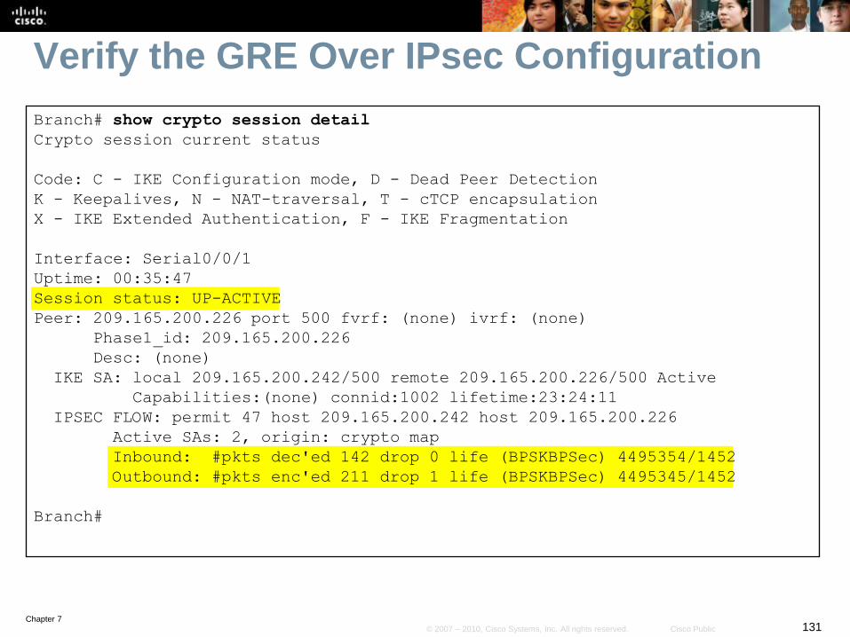
Chapter 7131© 2007 – 2010, Cisco Systems, Inc. All rights reserved. Cisco Public
Verify the GRE Over IPsec Configuration
Branch# show crypto session detail
Crypto session current status
Code: C - IKE Configuration mode, D - Dead Peer Detection
K - Keepalives, N - NAT-traversal, T - cTCP encapsulation
X - IKE Extended Authentication, F - IKE Fragmentation
Interface: Serial0/0/1
Uptime: 00:35:47
Session status: UP-ACTIVE
Peer: 209.165.200.226 port 500 fvrf: (none) ivrf: (none)
Phase1_id: 209.165.200.226
Desc: (none)
IKE SA: local 209.165.200.242/500 remote 209.165.200.226/500 Active
Capabilities:(none) connid:1002 lifetime:23:24:11
IPSEC FLOW: permit 47 host 209.165.200.242 host 209.165.200.226
Active SAs: 2, origin: crypto map
Inbound: #pkts dec'ed 142 drop 0 life (BPSKBPSec) 4495354/1452
Outbound: #pkts enc'ed 211 drop 1 life (BPSKBPSec) 4495345/1452
Branch#

Chapter 7132© 2007 – 2010, Cisco Systems, Inc. All rights reserved. Cisco Public
Planning for Mobile Worker Implementations

Chapter 7133© 2007 – 2010, Cisco Systems, Inc. All rights reserved. Cisco Public
Connecting a Mobile Worker
There are many challenges to connecting an increasingly
mobile workforce.
Mobile workers have become power users who may not
even need a full-time office but require a professional
environment and support services on-demand.
From collaboration to presence services, remote-access
solutions are an extension of the converged network and
present similar requirements in terms of security, quality of
service (QoS), and management transparency.

Chapter 7134© 2007 – 2010, Cisco Systems, Inc. All rights reserved. Cisco Public
Enterprise Mobile Worker Considerations
In addition to the regular email and Internet support, mobile
workers are increasingly requesting support for high-
bandwidth applications including:
• Mission-critical applications
• Real-time collaboration
• Voice
• Video
• Videoconferencing
Therefore, a major consideration when connecting a mobile
worker is the choice of a suitable network access
technology.

Chapter 7135© 2007 – 2010, Cisco Systems, Inc. All rights reserved. Cisco Public
Connecting Mobile Workers
Chapter 7136© 2007 – 2010, Cisco Systems, Inc. All rights reserved. Cisco Public
Enterprise Mobile Worker Considerations
Other mobile worker considerations include:
• Security
• Authentication
• IPsec and Secure Sockets Layer (SSL) VPNs
• Quality of Service (QoS):
• Management

Chapter 7137© 2007 – 2010, Cisco Systems, Inc. All rights reserved. Cisco Public
Enterprise Mobile Worker Considerations
Security:
• Security options safeguard the corporate network and close
unguarded back doors.
• Deploying firewall, intrusion prevention, and URL filtering services
meets most security needs.
Authentication:
• Authentication defines who gains access to resources.
• Identity-based network services using authentication, authorization,
and accounting (AAA) servers, 802.1X port-based access control,
Cisco security, and trust agents are used.
Chapter 7138© 2007 – 2010, Cisco Systems, Inc. All rights reserved. Cisco Public
Enterprise Mobile Worker Considerations
IPsec and Secure Sockets Layer (SSL) VPNs:
• Encrypts traffic traversing unsecure links.
• The type of VPN must be carefully considered and implemented
• Site-to-site VPNs provide an always-on transparent VPN connection.
• Remote access VPNs provide on-demand secured connections.
Quality of Service (QoS):
• QoS mechanisms prioritize the traffic and ensure adequate
performance for applications that are sensitive to delay and jitter (for
example, voice and video).

Chapter 7139© 2007 – 2010, Cisco Systems, Inc. All rights reserved. Cisco Public
Enterprise Mobile Worker Considerations
Management:
• Information Technology (IT) staff centrally manage and support
teleworker connections and equipment, and transparently configure
and push security and other policies to the remote devices.
• Tools are available that implement performance and fault
management and monitor service level agreements (SLAs).

Chapter 7140© 2007 – 2010, Cisco Systems, Inc. All rights reserved. Cisco Public
Business-Ready Mobile User Solution
The Cisco enterprise teleworker broadband solution to
deliver an always-on, secure voice and data service to
SOHOs creating a flexible work environment.
• The always-on VPN grants employees easy access to authorized
services and applications.
• Adding IP phones enhances productivity by allowing access to
centralized IP communications with voice and unified messaging.
• Centralized management minimizes support overhead and costs.
Integrated security allows easy extension of HQ security policies to
teleworkers.

Chapter 7141© 2007 – 2010, Cisco Systems, Inc. All rights reserved. Cisco Public
Connecting Mobile Workers
The choice of implementation will affect the routing solution.
Remote-Access VPN users will use a portable device (i.e., laptop) to initiate a VPN connection using either a VPN client software or an SSL Internet browser connection.
SOHO with a DSL Router
is an example of a
business-ready mobile
worker.
The routers maintain an
always-on site-to-site IPsec
VPN connection and the
VPN is completely hidden
to the user.

Chapter 7142© 2007 – 2010, Cisco Systems, Inc. All rights reserved. Cisco Public
Components for Mobile Workers
A mobile worker solution usually has three major components:
• Components located at the mobile worker’s remote site
• Corporate components located at the central site
• Optional IP telephony and other services.
• May be embedded into the user laptop via soft phones and other applications.

Chapter 7143© 2007 – 2010, Cisco Systems, Inc. All rights reserved. Cisco Public
Business-Ready VPN Components
Cisco Easy VPN Server :
• A Cisco IOS router or Cisco PIX / ASA Firewall configured as the VPN
headend device in site-to-site or remote-access VPNs.
And either:
• Cisco Easy VPN Remote:
• A Cisco IOS router or Cisco PIX / ASA Firewall acting as a remote VPN
client.
• Cisco Easy VPN Client
• An application supported on a PC used to access a Cisco VPN server.
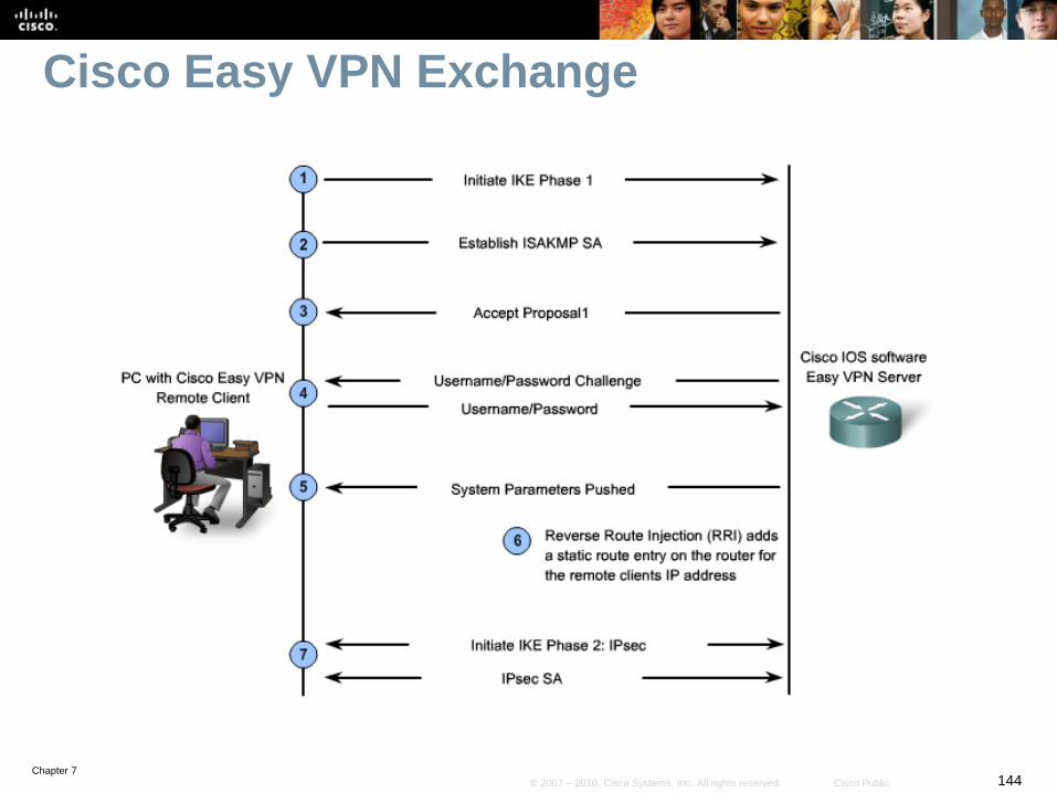
Chapter 7144© 2007 – 2010, Cisco Systems, Inc. All rights reserved. Cisco Public
Cisco Easy VPN Exchange

Chapter 7145© 2007 – 2010, Cisco Systems, Inc. All rights reserved. Cisco Public
Routing Traffic to the Mobile Worker
Chapter 7146© 2007 – 2010, Cisco Systems, Inc. All rights reserved. Cisco Public
Easy VPN Server
The Cisco Easy VPN server feature is usually configured on
the headend VPN router (typically the edge router).
• It concentrates the bulk of the remote-end configuration, which
“pushes” the policies to the client at the moment of connection.
At the remote end, the device used by the mobile worker is
known as the Easy VPN remote or Easy VPN client.
The Easy VPN remote device starts an IPsec VPN tunnel to
connect to the Easy VPN server across the public network.

Chapter 7147© 2007 – 2010, Cisco Systems, Inc. All rights reserved. Cisco Public
VPN Headend Router Implementation Plan
1. Allow IPsec traffic
2. Define an address pool for connecting clients.
3. Provide routing services for VPN subnets.
4. Tune NAT for VPN traffic flows.
5. Verify IPsec VPN configuration
Note:
• For simplicity reasons, the scenario used in the following steps are
loosely connected examples
• Therefore, the network and IP addressing may vary between steps.
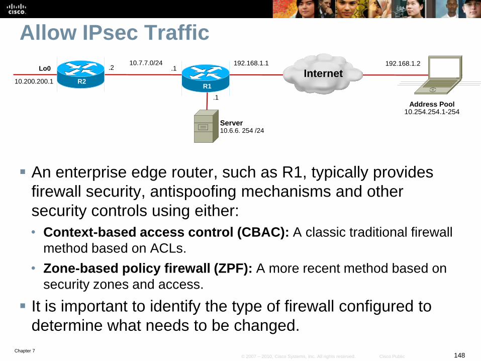
Chapter 7148© 2007 – 2010, Cisco Systems, Inc. All rights reserved. Cisco Public
Allow IPsec Traffic
An enterprise edge router, such as R1, typically provides
firewall security, antispoofing mechanisms and other
security controls using either:
• Context-based access control (CBAC): A classic traditional firewall
method based on ACLs.
• Zone-based policy firewall (ZPF): A more recent method based on
security zones and access.
It is important to identify the type of firewall configured to
determine what needs to be changed.
R2
Lo0
10.200.200.1R1
Address Pool10.254.254.1-254
Server10.6.6. 254 /24
10.7.7.0/24
Internet.1
.1
.2192.168.1.2192.168.1.1

Chapter 7149© 2007 – 2010, Cisco Systems, Inc. All rights reserved. Cisco Public
Allow IPsec Traffic - CBACs
R1# show ip interface fa0/1
Broadcast address is 255.255.255.255
Address determined by setup command
MTU is 1500 bytes
Helper address is not set
Directed broadcast forwarding is disabled
Multicast reserved groups joined: 224.0.0.10
Outgoing access list is not set
Inbound access list is FIREWALL-INBOUND
Proxy ARP is enabled
Local Proxy ARP is disabled
<output omitted>
R2
Lo0
10.200.200.1R1
Address Pool10.254.254.1-254
Server10.6.6. 254 /24
10.7.7.0/24
Internet.1
.1
.2192.168.1.2192.168.1.1
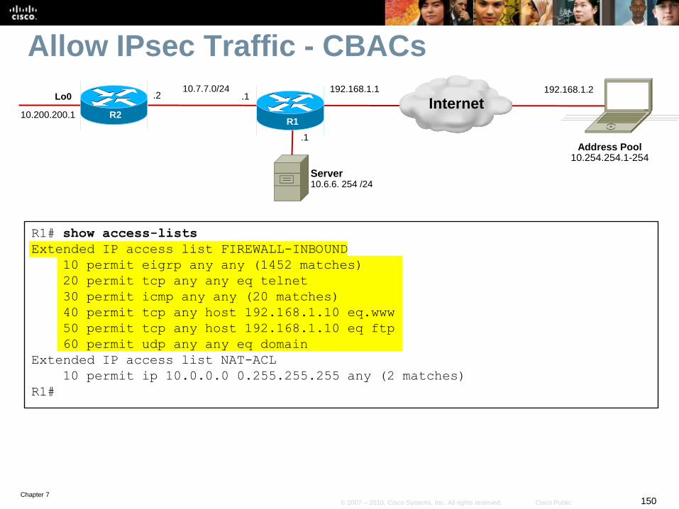
Chapter 7150© 2007 – 2010, Cisco Systems, Inc. All rights reserved. Cisco Public
Allow IPsec Traffic - CBACs
R1# show access-lists
Extended IP access list FIREWALL-INBOUND
10 permit eigrp any any (1452 matches)
20 permit tcp any any eq telnet
30 permit icmp any any (20 matches)
40 permit tcp any host 192.168.1.10 eq.www
50 permit tcp any host 192.168.1.10 eq ftp
60 permit udp any any eq domain
Extended IP access list NAT-ACL
10 permit ip 10.0.0.0 0.255.255.255 any (2 matches)
R1#
R2
Lo0
10.200.200.1R1
Address Pool10.254.254.1-254
Server10.6.6. 254 /24
10.7.7.0/24
Internet.1
.1
.2192.168.1.2192.168.1.1

Chapter 7151© 2007 – 2010, Cisco Systems, Inc. All rights reserved. Cisco Public
Allow IPsec Traffic - CBACsR1# show ip inspect interfaces
Interface Configuration
Interface FastEthernet0/0
Inbound inspection rule is INSPECTION
tcp alert is on audit-trail is off timeout 3600
udp alert is on audit-trail is off timeout 30
icmp alert is on audit-trail is off timeout 10
Outgoing inspection rule is not set
Inbound access list is ALL
Outgoing access list is not set
Interface FastEthernet0/1
Inbound inspection rule is INSPECTION
tcp alert is on audit-trail is off timeout 3600
udp alert is on audit-trail is off timeout 30
icmp alert is on audit-trail is off timeout 10
Outgoing inspection rule is not set
Inbound access list is FIREWALL-INBOUND
Outgoing access list is not set
R1#
R1# show zone-pair security
R1#
Lack of output indicates ZBF is not
configured.
Confirms that CBACs were configured.
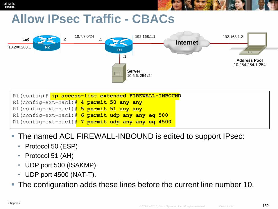
Chapter 7152© 2007 – 2010, Cisco Systems, Inc. All rights reserved. Cisco Public
Allow IPsec Traffic - CBACs
The named ACL FIREWALL-INBOUND is edited to support IPsec:
• Protocol 50 (ESP)
• Protocol 51 (AH)
• UDP port 500 (ISAKMP)
• UDP port 4500 (NAT-T).
The configuration adds these lines before the current line number 10.
R1(config)# ip access-list extended FIREWALL-INBOUND
R1(config-ext-nacl)# 4 permit 50 any any
R1(config-ext-nacl)# 5 permit 51 any any
R1(config-ext-nacl)# 6 permit udp any any eq 500
R1(config-ext-nacl)# 7 permit udp any any eq 4500
R2
Lo0
10.200.200.1R1
Address Pool10.254.254.1-254
Server10.6.6. 254 /24
10.7.7.0/24
Internet.1
.1
.2192.168.1.2192.168.1.1

Chapter 7153© 2007 – 2010, Cisco Systems, Inc. All rights reserved. Cisco Public
VPN Headend Router Implementation Plan
1. Allow IPsec traffic
2. Define an address pool for connecting clients.
3. Provide routing services for VPN subnets.
4. Tune NAT for VPN traffic flows.
5. Verify IPsec VPN configuration

Chapter 7154© 2007 – 2010, Cisco Systems, Inc. All rights reserved. Cisco Public
Defining an Address Pool
The 192.168.1.2 address is the reachable outside address.
• However, the remote host requires an internal private address.
The pool named EZVPN provides addresses from the 10.254.254.0 /24 subnet to be allocated to the remote hosts.
Note:
• Although in this example the 192.168.1.x address is used, the actual pool would normally be a routed (public) address.
R1# config t
R1(config)# ip local pool EZVPN 10.254.254.1 10.254.254.254
R1(config)#
R2
Lo0
10.200.200.1R1
Address Pool10.254.254.1-254
Server10.6.6. 254 /24
10.7.7.0/24
Internet.1
.1
.2192.168.1.2192.168.1.1
Chapter 7155© 2007 – 2010, Cisco Systems, Inc. All rights reserved. Cisco Public
VPN Headend Router Implementation Plan
1. Allow IPsec traffic.
2. Define an address pool for connecting clients.
3. Provide routing services for VPN subnets.
4. Tune NAT for VPN traffic flows.
5. Verify IPsec VPN configuration.

Chapter 7156© 2007 – 2010, Cisco Systems, Inc. All rights reserved. Cisco Public
Routing Services for VPN Subnets
Several methods can be used to advertise the address pool
in the internal network including:
• Proxy ARP
• Static routes with redistribution
• Reverse route injection (RRI)

Chapter 7157© 2007 – 2010, Cisco Systems, Inc. All rights reserved. Cisco Public
Routing Services - Proxy ARP
Proxy ARP (simplest method) involves selecting the
address pool as a subnet of an existing physical segment.
For example:
• Remote users subnet: 192.168.1.128/26
• Internal network subnet: 192.168.1.0/24.
It is enabled using the ip proxy-arp interface
configuration command.
Advantages:
• No additional subnets are required.
• No routing configuration changes are required.
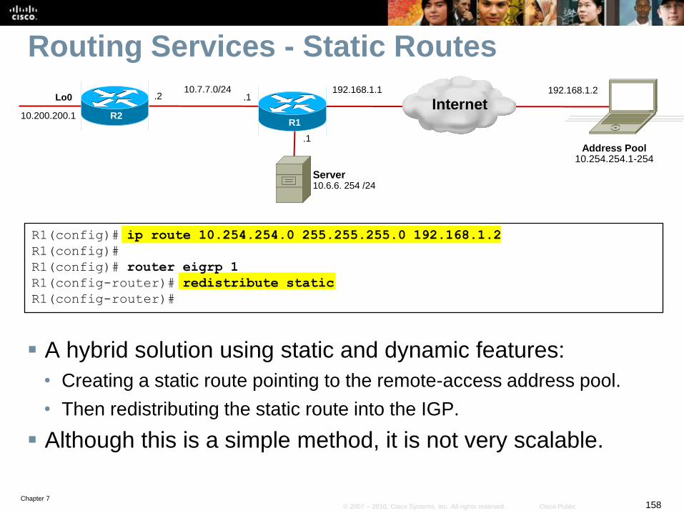
Chapter 7158© 2007 – 2010, Cisco Systems, Inc. All rights reserved. Cisco Public
Routing Services - Static Routes
A hybrid solution using static and dynamic features:
• Creating a static route pointing to the remote-access address pool.
• Then redistributing the static route into the IGP.
Although this is a simple method, it is not very scalable.
R1(config)# ip route 10.254.254.0 255.255.255.0 192.168.1.2
R1(config)#
R1(config)# router eigrp 1
R1(config-router)# redistribute static
R1(config-router)#
R2
Lo0
10.200.200.1R1
Address Pool10.254.254.1-254
Server10.6.6. 254 /24
10.7.7.0/24
Internet.1
.1
.2192.168.1.2192.168.1.1
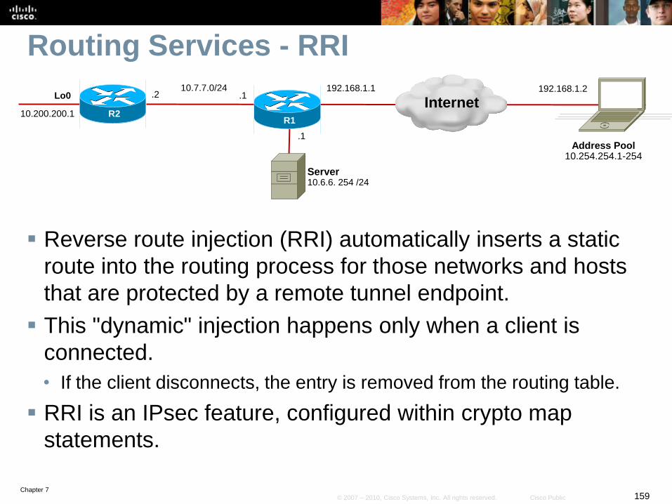
Chapter 7159© 2007 – 2010, Cisco Systems, Inc. All rights reserved. Cisco Public
Routing Services - RRI
Reverse route injection (RRI) automatically inserts a static
route into the routing process for those networks and hosts
that are protected by a remote tunnel endpoint.
This "dynamic" injection happens only when a client is
connected.
• If the client disconnects, the entry is removed from the routing table.
RRI is an IPsec feature, configured within crypto map
statements.
R2
Lo0
10.200.200.1R1
Address Pool10.254.254.1-254
Server10.6.6. 254 /24
10.7.7.0/24
Internet.1
.1
.2192.168.1.2192.168.1.1
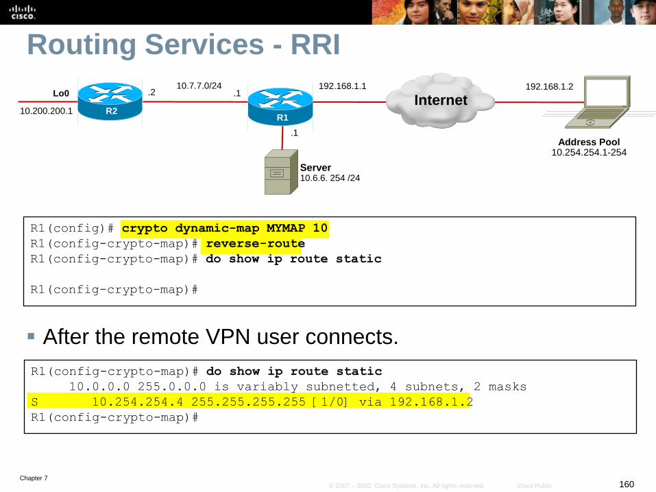
Chapter 7160© 2007 – 2010, Cisco Systems, Inc. All rights reserved. Cisco Public
Routing Services - RRI
After the remote VPN user connects.
R1(config)# crypto dynamic-map MYMAP 10
R1(config-crypto-map)# reverse-route
R1(config-crypto-map)# do show ip route static
R1(config-crypto-map)#
R1(config-crypto-map)# do show ip route static
10.0.0.0 255.0.0.0 is variably subnetted, 4 subnets, 2 masks
S 10.254.254.4 255.255.255.255 [1/0] via 192.168.1.2
R1(config-crypto-map)#
R2
Lo0
10.200.200.1R1
Address Pool10.254.254.1-254
Server10.6.6. 254 /24
10.7.7.0/24
Internet.1
.1
.2192.168.1.2192.168.1.1
Chapter 7161© 2007 – 2010, Cisco Systems, Inc. All rights reserved. Cisco Public
Routing Services - RRI Drawback
One drawback of RRI is that entries are added with a host
mask, a mask of 32 bits in the routing table.
If there are hundreds of remote clients that connect
simultaneously, that could result in a very long routing table.

Chapter 7162© 2007 – 2010, Cisco Systems, Inc. All rights reserved. Cisco Public
VPN Headend Router Implementation Plan
1. Allow IPsec traffic.
2. Define an address pool for connecting clients.
3. Provide routing services for VPN subnets.
4. Tune NAT for VPN traffic flows.
5. Verify IPsec VPN configuration.

Chapter 7163© 2007 – 2010, Cisco Systems, Inc. All rights reserved. Cisco Public
Tune NAT for VPN traffic
A packet is processed through the NAT engine before it is
forwarded to the IPsec engine.
• Tuning of NAT when implementing VPNs is often necessary.
VPN traffic should not be translated by NAT and should
therefore be exempted from translation.
• To do so, the NAT ACL will have to be edited.
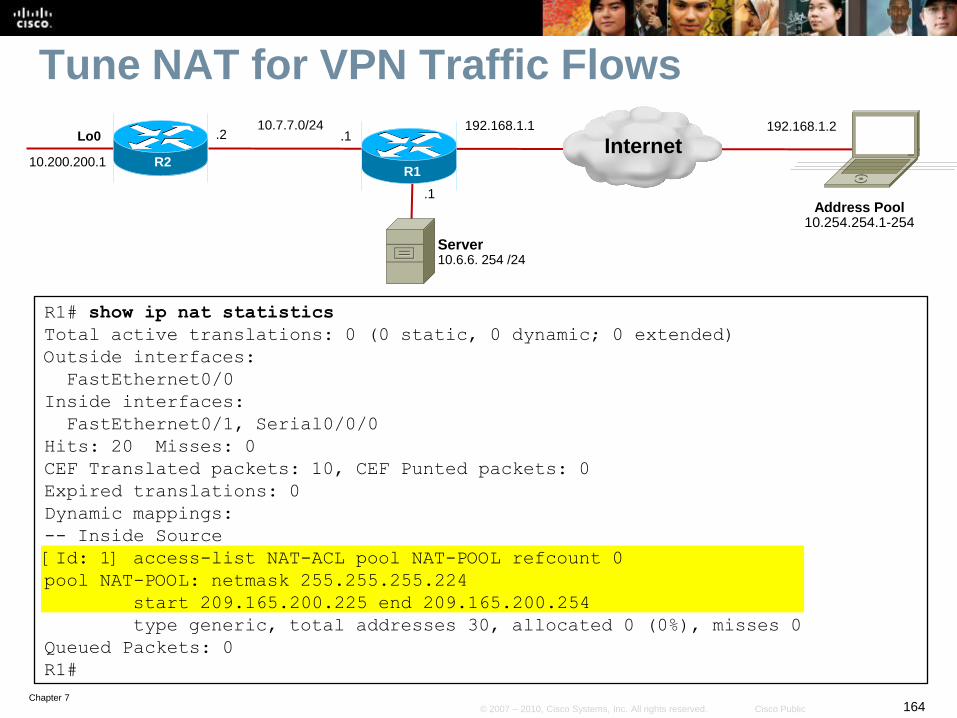
Chapter 7164© 2007 – 2010, Cisco Systems, Inc. All rights reserved. Cisco Public
Tune NAT for VPN Traffic Flows
R1# show ip nat statistics
Total active translations: 0 (0 static, 0 dynamic; 0 extended)
Outside interfaces:
FastEthernet0/0
Inside interfaces:
FastEthernet0/1, Serial0/0/0
Hits: 20 Misses: 0
CEF Translated packets: 10, CEF Punted packets: 0
Expired translations: 0
Dynamic mappings:
-- Inside Source
[Id: 1] access-list NAT-ACL pool NAT-POOL refcount 0
pool NAT-POOL: netmask 255.255.255.224
start 209.165.200.225 end 209.165.200.254
type generic, total addresses 30, allocated 0 (0%), misses 0
Queued Packets: 0
R1#
R2
Lo0
10.200.200.1R1
Address Pool10.254.254.1-254
Server10.6.6. 254 /24
10.7.7.0/24
Internet.1
.1
.2192.168.1.2192.168.1.1

Chapter 7165© 2007 – 2010, Cisco Systems, Inc. All rights reserved. Cisco Public
Tune NAT for VPN Traffic Flows
R1# show ip access-lists
Extended IP access list FIREWALL-INBOUND
4 permit esp any any
5 permit ahp any any
6 permit udp any any eq isakmp
7 permit udp any any eq non500-isakmp
10 permit eigrp any any
20 permit tcp any any eq telnet
30 permit icmp any any
40 permit tcp any host 192.168.1.10 eq www
50 permit tcp any host 192.168.1.10 eq ftp
60 permit udp any any eq domain
Extended IP access list NAT-ACL
10 permit ip 10.0.0.0 0.255.255.255 any
R1#
R2
Lo0
10.200.200.1R1
Address Pool10.254.254.1-254
Server10.6.6. 254 /24
10.7.7.0/24
Internet.1
.1
.2192.168.1.2192.168.1.1

Chapter 7166© 2007 – 2010, Cisco Systems, Inc. All rights reserved. Cisco Public
Tune NAT for VPN Traffic Flows
R1# config t
R1(config)# ip access-list extended NAT-ACL
R1(config-ext-nacl)# 5 deny ip any 10.254.254.0 0.0.0.255
R1(config-ext-nacl)# end
R1#
10.200.200.1 R2
Lo0
10.200.200.1R1
Address Pool10.254.254.1-254
Server10.6.6. 254 /24
10.7.7.0/24
Internet.1
.1
.2192.168.1.2192.168.1.1

Chapter 7167© 2007 – 2010, Cisco Systems, Inc. All rights reserved. Cisco Public
Tune NAT for VPN Traffic Flows
R1# show ip access-lists
Extended IP access list FIREWALL-INBOUND
4 permit esp any any
5 permit ahp any any
6 permit udp any any eq isakmp
7 permit udp any any eq non500-isakmp
10 permit eigrp any any
20 permit tcp any any eq telnet
30 permit icmp any any
40 permit tcp any host 192.168.1.10 eq www
50 permit tcp any host 192.168.1.10 eq ftp
60 permit udp any any eq domain
Extended IP access list NAT-ACL
5 deny ip any 10.254.254.0 0.0.0.255
10 permit ip 10.0.0.0 0.255.255.255 any
R1#
R2
Lo0
10.200.200.1R1
Address Pool10.254.254.1-254
Server10.6.6. 254 /24
10.7.7.0/24
Internet.1
.1
.2192.168.1.2192.168.1.1

Chapter 7168© 2007 – 2010, Cisco Systems, Inc. All rights reserved. Cisco Public
VPN Headend Router Implementation Plan
1. Allow IPsec traffic.
2. Define an address pool for connecting clients.
3. Provide routing services for VPN subnets.
4. Tune NAT for VPN traffic flows.
5. Verify IPsec VPN configuration.
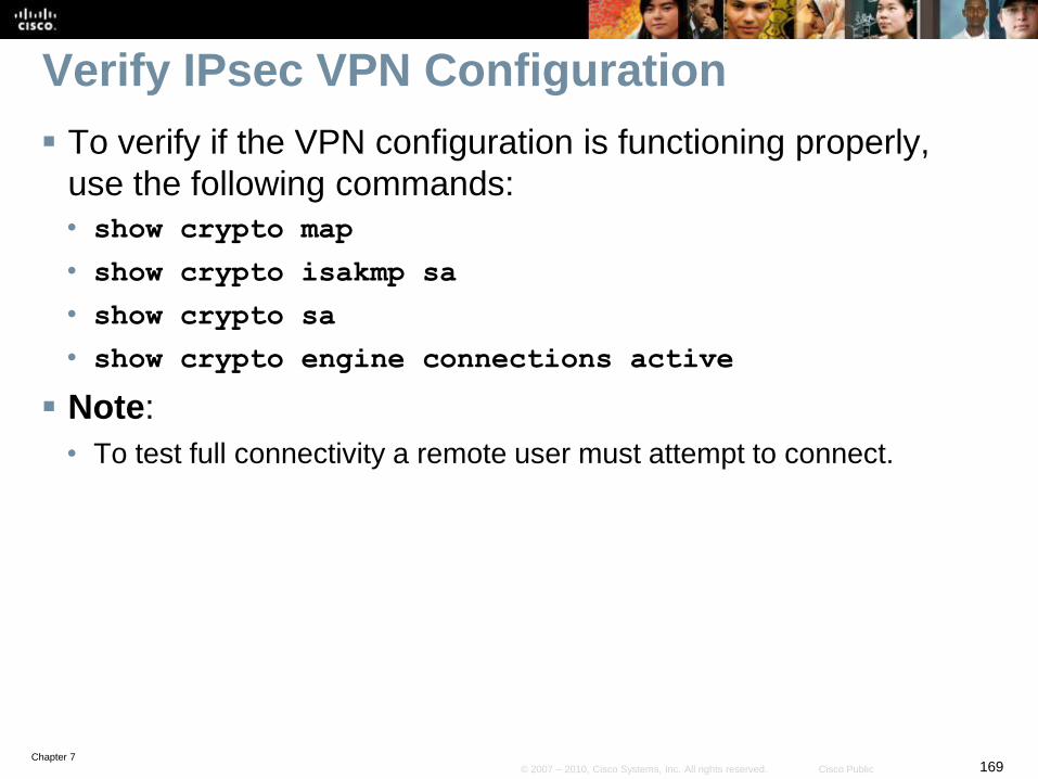
Chapter 7169© 2007 – 2010, Cisco Systems, Inc. All rights reserved. Cisco Public
Verify IPsec VPN Configuration
To verify if the VPN configuration is functioning properly,
use the following commands:
• show crypto map
• show crypto isakmp sa
• show crypto sa
• show crypto engine connections active
Note:
• To test full connectivity a remote user must attempt to connect.

Chapter 7170© 2007 – 2010, Cisco Systems, Inc. All rights reserved. Cisco Public
Remote Users Connections
Mobile users can connect to the central office using either:
• VPN Client software from their laptops
• SSL VPN
The choice of method will depend on the needs of the
remote user.
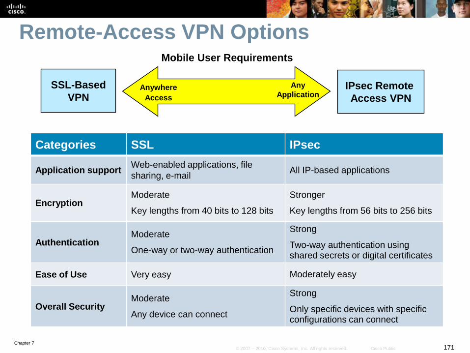
Chapter 7171© 2007 – 2010, Cisco Systems, Inc. All rights reserved. Cisco Public
Remote-Access VPN Options
Categories SSL IPsec
Application supportWeb-enabled applications, file
sharing, e-mailAll IP-based applications
EncryptionModerate
Key lengths from 40 bits to 128 bits
Stronger
Key lengths from 56 bits to 256 bits
AuthenticationModerate
One-way or two-way authentication
Strong
Two-way authentication using shared secrets or digital certificates
Ease of Use Very easy Moderately easy
Overall SecurityModerate
Any device can connect
Strong
Only specific devices with specific configurations can connect
IPsec Remote
Access VPN
SSL-Based
VPNAnywhere
Access
Any
Application
Mobile User Requirements
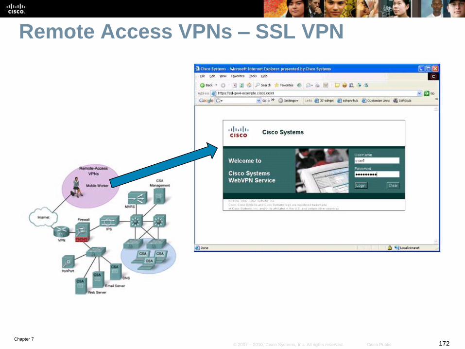
Chapter 7172© 2007 – 2010, Cisco Systems, Inc. All rights reserved. Cisco Public
Remote Access VPNs – SSL VPN
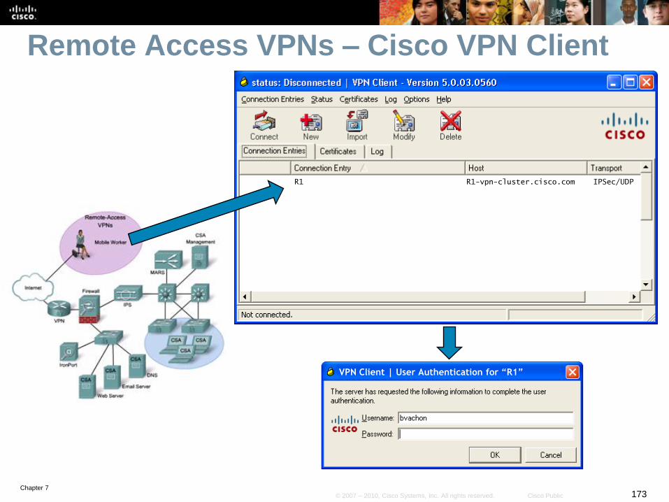
Chapter 7173© 2007 – 2010, Cisco Systems, Inc. All rights reserved. Cisco Public
Remote Access VPNs – Cisco VPN Client
VPN Client | User Authentication for “R1”
R1 R1-vpn-cluster.cisco.com IPSec/UDP

Chapter 7174© 2007 – 2010, Cisco Systems, Inc. All rights reserved. Cisco Public
Remote Access VPNs – Cisco VPN Client
R1

Chapter 7175© 2007 – 2010, Cisco Systems, Inc. All rights reserved. Cisco Public
Verify Remote Access VPNs Connectivity

Chapter 7176© 2007 – 2010, Cisco Systems, Inc. All rights reserved. Cisco Public
Chapter 7 Summary
The chapter focused on the following topics:
Planning the branch office implementation
Analyzing services in the branch office
Planning for mobile worker implementations
Routing traffic to the mobile worker

Chapter 7177© 2007 – 2010, Cisco Systems, Inc. All rights reserved. Cisco Public
Chapter 7 Lab
Lab 7-1 Configure Routing Facilities to the Branch Office

Chapter 7178© 2007 – 2010, Cisco Systems, Inc. All rights reserved. Cisco Public
Resources
Cisco IOS Software Releases 12.4 Mainline
• http://www.cisco.com/en/US/products/ps6350/tsd_products_support_s
eries_home.html
The Cisco IOS Command Reference
• http://www.cisco.com/en/US/products/ps6350/prod_command_referen
ce_list.html

Chapter 7179© 2007 – 2010, Cisco Systems, Inc. All rights reserved. Cisco Public
Lab 7-1 Configure Routing Facilities to the Branch
Office
Chapter 7 Labs

Chapter 7180© 2007 – 2010, Cisco Systems, Inc. All rights reserved. Cisco Public