routing and action memorandum · routing and action memorandum routing to: (1) electronics division...
TRANSCRIPT
ROUTING AND ACTION
MEMORANDUM
ROUTING
TO: (1) Electronics Division (Clark, William)
Report is available for review
(2) Proposal Files Proposal No.:
CONTRACT OR GRANT NUMBER:
DESCRIPTION OF MATERIAL
INSTITUTION:
PRINCIPAL INVESTIGATOR: Peter Burke
TYPE REPORT: MS Thesis
PERIOD COVERED: through
DATE RECEIVED: 8/29/13 1:53PM
(x) Report has been reviewed for technical sufficiency and IS [x] IS NOT [ ] satisfactory.
ACTION TAKEN BY DIVISION
W911NF-09-1-0319
University of California - Irvine
TITLE: IMMOBILIZATION of MITOCHONDRIA on GRAPHENE
(x) Material has been given an OPSEC review and it has been determined to be non sensitive and, except for manuscripts and progress reports, suitable for public release.
Approved by SSL\WILLIAM.CLARK on 10/8/14 3:30PM
56426EL.31
ARO FORM 36-E

The public reporting burden for this collection of information is estimated to average 1 hour per response, including the time for reviewing instructions,
searching existing data sources, gathering and maintaining the data needed, and completing and reviewing the collection of information. Send comments
regarding this burden estimate or any other aspect of this collection of information, including suggesstions for reducing this burden, to Washington
Headquarters Services, Directorate for Information Operations and Reports, 1215 Jefferson Davis Highway, Suite 1204, Arlington VA, 22202-4302.
Respondents should be aware that notwithstanding any other provision of law, no person shall be subject to any oenalty for failing to comply with a collection of
information if it does not display a currently valid OMB control number.
PLEASE DO NOT RETURN YOUR FORM TO THE ABOVE ADDRESS.
a. REPORT
IMMOBILIZATION of MITOCHONDRIA on GRAPHENE
14. ABSTRACT
16. SECURITY CLASSIFICATION OF:
The research on mitochondria has been the focus of many scientists since the discovery of mitochondria DNA
mutation as a cause of many health diseases and its major role in apoptosis. Various work has been done to measure
the membrane potential of mitochondria which can inform scientists of the health state of the cells.
The objective of this study was to learn more about mitochondria’s surface properties and to consequently
immobilize mitochondria on graphene. The surface of graphene was coated with Polyethyleneimine (PEI),
1. REPORT DATE (DD-MM-YYYY)
4. TITLE AND SUBTITLE
29-08-2013
13. SUPPLEMENTARY NOTES
The views, opinions and/or findings contained in this report are those of the author(s) and should not contrued as an official Department
of the Army position, policy or decision, unless so designated by other documentation.
12. DISTRIBUTION AVAILIBILITY STATEMENT
Approved for public release; distribution is unlimited.
UU
9. SPONSORING/MONITORING AGENCY NAME(S) AND
ADDRESS(ES)
6. AUTHORS
7. PERFORMING ORGANIZATION NAMES AND ADDRESSES
U.S. Army Research Office
P.O. Box 12211
Research Triangle Park, NC 27709-2211
15. SUBJECT TERMS
Mitochondria, Graphene, Immobilization, Polymer, Fluorescence microscopy, Dye
Elaheh Shekaramiz
University of California - Irvine
5171 California Avenue, Suite 150
Irvine, CA 92697 -7600
REPORT DOCUMENTATION PAGE
b. ABSTRACT
UU
c. THIS PAGE
UU
2. REPORT TYPE
MS Thesis
17. LIMITATION OF
ABSTRACT
UU
15. NUMBER
OF PAGES
5d. PROJECT NUMBER
5e. TASK NUMBER
5f. WORK UNIT NUMBER
5c. PROGRAM ELEMENT NUMBER
5b. GRANT NUMBER
5a. CONTRACT NUMBER
W911NF-09-1-0319
611102
Form Approved OMB NO. 0704-0188
56426-EL.31
11. SPONSOR/MONITOR'S REPORT
NUMBER(S)
10. SPONSOR/MONITOR'S ACRONYM(S)
ARO
8. PERFORMING ORGANIZATION REPORT
NUMBER
19a. NAME OF RESPONSIBLE PERSON
19b. TELEPHONE NUMBER
Peter Burke
949-824-9326
3. DATES COVERED (From - To)
Standard Form 298 (Rev 8/98)
Prescribed by ANSI Std. Z39.18
-

IMMOBILIZATION of MITOCHONDRIA on GRAPHENE
Report Title
ABSTRACT
The research on mitochondria has been the focus of many scientists since the discovery of mitochondria DNA
mutation as a cause of many health diseases and its major role in apoptosis. Various work has been done to measure
the membrane potential of mitochondria which can inform scientists of the health state of the cells.
The objective of this study was to learn more about mitochondria’s surface properties and to consequently
immobilize mitochondria on graphene. The surface of graphene was coated with Polyethyleneimine (PEI),
Poly-L-Lysine (PLL), Lipid bilayer, and Polyethylene glycol (PEG) to study the immobilization of mitochondria on
graphene. The technique used to remove unattached mitochondria as well as the staining method were both crucial
factors in adhesion of mitochondria to the surface of graphene.

UNIVERSITY OF CALIFORNIA, IRVINE
IMMOBILIZATION of MITOCHONDRIA on GRAPHENE
THESIS
submitted in partial satisfaction of the requirements for the degree of
MASTER OF SCIENCE
in Biomedical Engineering
by
Elaheh Shekaramiz
Thesis committee:
Peter J. Burke, Ph.D., Chair
Marc Madou, Ph.D.
James P. Brody, Ph.D.
2012

© 2012 Elaheh Shekaramiz

ii
TABLE OF CONTENTS
List of Figures ................................................................................................................................... v
List of Tables .................................................................................................................................. vii
Acknowledgements ....................................................................................................................... viii
Abstracts of the Dissertation .......................................................................................................... ix
Chapter 1: Introduction .................................................................................................................. 1
1.1 Mitochondria ......................................................................................................................... 2
1.1.1 Structure of Mitochondria .............................................................................................. 2
1.1.2 Membrane Potential of Mitochondria ........................................................................... 5
Chapter 2: Graphene....................................................................................................................... 7
2.2.1 Structure of Graphene ....................................................................................................... 8
2.2.2 Application and Properties of Graphene ......................................................................... 10
2.3 Dyes ..................................................................................................................................... 11
2.3.1 JC-1 Dye ........................................................................................................................ 11
2.3.2 TMRM Dye .................................................................................................................... 12
Chapter 3: Polyethyleneimine(PEI), Poly-L-lysine(PLL), Polyethylene glycol(PEG) ....................... 13
3.1 Current Technologies in Immobilization of Mitochondria .................................................. 14
3.2 Polyethyleneimine (PEI) ...................................................................................................... 16
3.2.1 Structure of PEI ............................................................................................................. 16
3.2.2 Applications of PEI ........................................................................................................ 17
3.3 Poly-L-lysine (PLL) ................................................................................................................ 19
3.3.1 Structure of PLL ............................................................................................................ 19
3.3.2 Applications of PLL ........................................................................................................ 19
3.4 Lipid Bilayer ......................................................................................................................... 20
3.5 Polyethylene glycol (PEG) .................................................................................................... 23
3.5.1 Structure of PEG ........................................................................................................... 23
3.5.2 Properties of PEG .......................................................................................................... 23
iii
3.5.3 Applications of PEG....................................................................................................... 24
Chapter 4: Materials and Methods ............................................................................................... 25
4.1 Materials ............................................................................................................................. 26
4.2 Methods .............................................................................................................................. 26
4.2.1 Experimental Set Up ..................................................................................................... 26
4.2.2 Transfer Method of Graphene Film .............................................................................. 27
4.2.3 Coating of Graphene on Glass Slides ............................................................................ 27
4.2.4 Preparation of Lipid Bilayer .......................................................................................... 28
4.2.5 PDMS Preparation ........................................................................................................ 28
4.2.6 Channel Preparation ..................................................................................................... 28
4.2.7 Preparation of Buffers .................................................................................................. 29
4.2.8 Isolation of Mitochondria ............................................................................................. 29
4.2.9 JC-1 Preparation ........................................................................................................... 30
4.2.10 TMRM Preparation ..................................................................................................... 30
4.2.11 Imaging of Mitochondria ............................................................................................ 31
Chapter 5: Results ......................................................................................................................... 32
5.1 JC-1 Dye ............................................................................................................................... 33
5.1.1 Glass .............................................................................................................................. 33
5.1.2 Graphene ...................................................................................................................... 34
5.1.3 PLL ................................................................................................................................. 35
5.1.4 Lipid Bilayer .................................................................................................................. 36
5.1.5 PEG ................................................................................................................................ 37
5.1.6 PEI ................................................................................................................................. 38
5.2 TMRM Dye ........................................................................................................................... 39
5.2.1 Glass .............................................................................................................................. 39
5.2.2 Graphene ...................................................................................................................... 40
5.2.3 PLL ................................................................................................................................. 41
5.2.4 Lipid Bilayer .................................................................................................................. 42
5.2.5 PEG ................................................................................................................................ 43

iv
5.2.6 PEI ................................................................................................................................. 44
Chapter 6: Discussion and Conclusion .......................................................................................... 46
6.1 Discussion ............................................................................................................................ 47
6.2 Conclusion ........................................................................................................................... 49
References .................................................................................................................................... 50
v
LIST OF FIGURES
Figure 1-1. Mitochondria Compartments ....................................................................................... 3
Figure 1-2. ATP synthesis ................................................................................................................ 5
Figure 2-1. Single layer structure of graphene ............................................................................... 8
Figure 2-2. Schematic of in plane sigma bonds and perpendicular pi bonds ................................. 9
Figure 2-3. Different ways of stacking carbon atoms ..................................................................... 9
Figure 2-4. Chemical structure of JC-1 .......................................................................................... 11
Figure 2-5. Chemical structure of TMRM...................................................................................... 12
Figure 3-1. Structure of linear polyethyleneimine........................................................................ 16
Figure 3-2. Structure of branched polyethyleneimine ................................................................. 17
Figure 3-3. PEI application in gene delivery .................................................................................. 18
Figure 3-4. Molecular structure of poly-L-lysine........................................................................... 19
Figure 3-5. Immobilization of DNA on the PLL coated electrode ................................................. 20
Figure 3-6. Structure of lipid bilayer ............................................................................................. 21
Figure 3-7. Structure of an artificial vesicle, liposome ................................................................. 22
Figure 3-8. Molecular structure of PEG ........................................................................................ 23
Figure 3-9. PEGylation of drugs to increase solubility .................................................................. 24
Figure 4-1. Graphene film on copper foil...................................................................................... 26
Figure 5-1. Mitochondria on glass before washing ...................................................................... 33
Figure 5-2. Mitochondria on graphene before washing ............................................................... 34
Figure 5-3. Mitochondria inside PLL coated graphene chamber .................................................. 35
Figure 5-4. Lipid bilayer on top of glass before addition of mitochondria ................................... 36
Figure 5-5. Mitochondria on lipid bilayer coated graphene ......................................................... 36
Figure 5-6. Mitochondria inside PEG coated graphene chamber before washing....................... 37
Figure 5-7. Mitochondria on PEI coated graphene ....................................................................... 38
Figure 5-8. Mitochondria inside the glass chamber before washing ........................................... 39
Figure 5-9. Mitochondria inside the graphene chamber before washing .................................... 40
Figure 5-10. Mitochondria inside PLL coated chamber ................................................................ 41

vi
Figure 5-11. Mitochondria inside lipid bilayer coated chamber before and after washing ......... 42
Figure 5-12. Mitochondria on PEG coated graphene surface before washing ............................ 43
Figure 5-13. Mitochondria inside PEI coated graphene surface .................................................. 44

vii
LIST OF TABLES
Table 5-1 Results of immobilization of mitochondria on graphene with Jc-1 dye ....................... 44
Table 5-2 Results of immobilization of mitochondria on graphene with TMRM dye .................. 45

viii
ACKNOWLEDGEMENTS
I would like to thank my advisor, Professor Peter Burke, for his great support during my
studies. This work would have not been possible without his guidance and encouragement. It
was an honor to work for him. I am also grateful to my group mates for all their help and
friendships.
I am also extremely thankful of my parents, my family, and my friends for their
invaluable support. I would like to particularly express my great appreciation for my mother,
who has always been encouraging me to further expand my knowledge and has always been
there for me in ups and downs of my life.

ix
ABSTRACT OF THE THESIS
Immobilization of Mitochondria on Graphene
By
Elaheh Shekaramiz
Master of Science in Biomedical Engineering
University of California, Irvine, 2012
Professor Peter J. Burke, Chair
The research on mitochondria has been the focus of many scientists since the discovery
of mitochondria DNA mutation as a cause of many health diseases and its major role in
apoptosis. Various work has been done to measure the membrane potential of mitochondria
which can inform scientists of the health state of the cells.
The objective of this study was to learn more about mitochondria’s surface properties
and to consequently immobilize mitochondria on graphene. The surface of graphene was
coated with Polyethyleneimine (PEI), Poly-L-Lysine (PLL), Lipid bilayer, and Polyethylene glycol
(PEG) to study the immobilization of mitochondria on graphene. The technique used to remove
unattached mitochondria as well as the staining method were both crucial factors in adhesion
of mitochondria to the surface of graphene.

1
CHAPTER 1: INTRODUCTION

2
Mitochondria
Mitochondria have important functions such as Adenosine-5'-triphosphate (ATP)
production, regulation of cellular metabolism and apoptosis. Dysfunction of mitochondria may
lead to a lot of diseases including cancer, and age-related diseases (Desler,C. eta al. 2011). In
order to study the mitochondrial membrane potential, mitochondria should be immobilized on
a surface and it must be stained. The structure and properties of the surface (graphene) as well
as the staining dyes used in this study are going to be discussed in chapter 2. The surface of
graphene needs to be coated so that mitochondria can adhere to it. The coating materials are
discussed in chapter 3. In chapter 4, materials and methods of this experiment are proposed.
Chapter 5 is the results and chapter 6 is the discussion and conclusion of this study.
Structure of Mitochondria
Mitochondria are membrane bound organelles in eukaryotic cells. Their diameter ranges
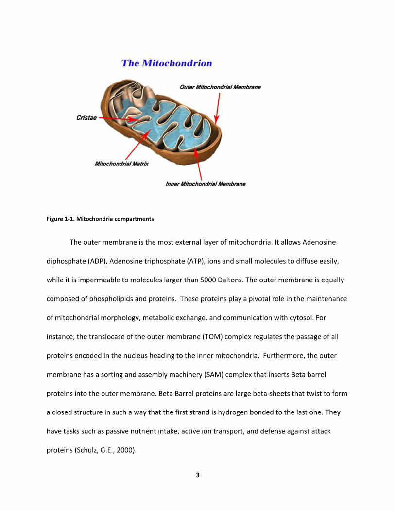
from 0.5 to 1.0μm. These organelles are comprised of 4 major compartments: outer
membrane, inner membrane, cristae, and matrix (Figure 1-1).
3
Figure 1-1. Mitochondria compartments
The outer membrane is the most external layer of mitochondria. It allows Adenosine
diphosphate (ADP), Adenosine triphosphate (ATP), ions and small molecules to diffuse easily,
while it is impermeable to molecules larger than 5000 Daltons. The outer membrane is equally
composed of phospholipids and proteins. These proteins play a pivotal role in the maintenance
of mitochondrial morphology, metabolic exchange, and communication with cytosol. For
instance, the translocase of the outer membrane (TOM) complex regulates the passage of all
proteins encoded in the nucleus heading to the inner mitochondria. Furthermore, the outer
membrane has a sorting and assembly machinery (SAM) complex that inserts Beta barrel
proteins into the outer membrane. Beta Barrel proteins are large beta-sheets that twist to form
a closed structure in such a way that the first strand is hydrogen bonded to the last one. They
have tasks such as passive nutrient intake, active ion transport, and defense against attack
proteins (Schulz, G.E., 2000).

4
The inner membrane is impermeable to ions and molecules because the phospholipids
in its lipid bilayer contain four fatty acids instead of two. Small molecules pass the inner
membrane through the translocase of inner membrane (TIM) protein. The inner mitochondria
membrane folds to create cristae, which results in a large surface area (Figure 1-1).
The cristae accommodate several vital proteins that contribute to the main functions of
mitochondria including ATP synthase and cytochromes. ATP synthase is the enzyme that
converts energy of protons to ATP through the following reaction:
ATP synthase + ADP + Pi → ATP Synthase + ATP
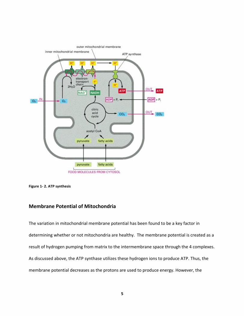
The inner membrane of mitochondria also surrounds the matrix of mitochondria. The
matrix contains enzymes, ribosomes, tRNAs, and copies of mitochondrial DNA genome. It also
has a role in production of ATP through the citric cycle. The enzymes of the matrix metabolize
fatty acids and pyruvate to produce acetyl CoA. In addition, these enzymes oxidize acetyl CoA to
produce CO2 and NADH in the citric acid cycle. NADH is later used as a carrier in the electron
transport chain process to transfer the electrons across the membrane. The electron transport
chain includes 4 complexes (Alberts B, et al., 2002). The transport of electrons creates a proton
gradient across the inner membrane of mitochondria which is responsible for the production of
ATP (Figure 1-2).
5
Figure 1- 2. ATP synthesis
Membrane Potential of Mitochondria
The variation in mitochondrial membrane potential has been found to be a key factor in
determining whether or not mitochondria are healthy. The membrane potential is created as a
result of hydrogen pumping from matrix to the intermembrane space through the 4 complexes.
As discussed above, the ATP synthase utilizes these hydrogen ions to produce ATP. Thus, the
membrane potential decreases as the protons are used to produce energy. However, the

6
membrane potential is maintained by pumping more protons across the membrane. The
change in membrane potential is a signal for mitochondrial dysfunction (Lim,T. 2011).

7
CHAPTER 2: GRAPHENE

8
Graphene
Structure of Graphene
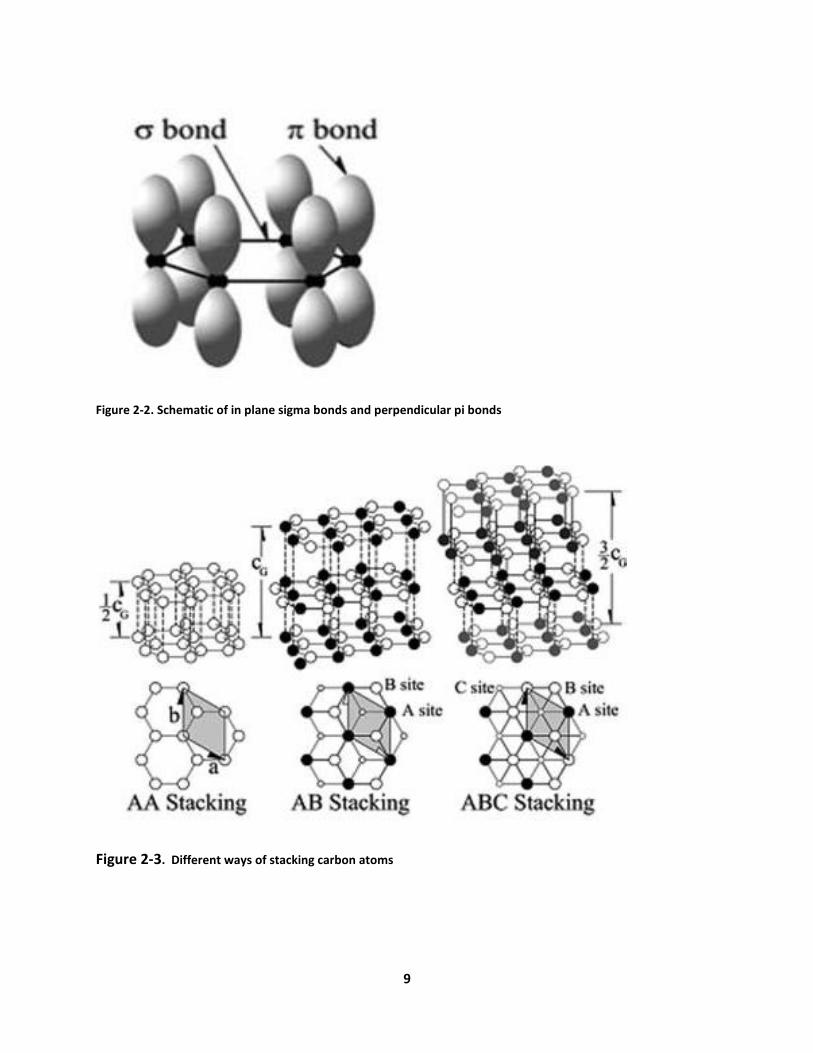
A single layered graphene is a 2D planer sheet composed of SP2 bonded carbon atoms
(Figure 2-1). Carbon atoms are bonded through in-plane σ bonds and perpendicular π orbitals(
Figure 2-2). Bi-layer and few-layered graphenes have 2 or more of the 2D sheets of graphene.
As can be seen in figure 2-3, Carbon atoms can be stacked as AA, AB, or ABC (Figure 2-3).
Figure 2-1. Single layer structure of graphene
9
Figure 2-2. Schematic of in plane sigma bonds and perpendicular pi bonds
Figure 2-3. Different ways of stacking carbon atoms
10
Application and properties of Graphene
Graphene is synthesized in different ways depending on its application (Dale, A.C.,et
al., 2010). Various methods of synthesis of graphene include exfoliation and cleavage, thermal
chemical vapor deposition, plasma enhanced chemical vapor deposition, thermal deposition of
silicon carbide (SiC), thermal deposition on other substrates, chemical methods, and Un-zipping
carbon nanotubes (CNTs) (Choi, W.et al, 2010). However, the most common method of
graphene production is through chemical modification of graphite (Kauffman, D.R., 2010).
Relative to CNTs, graphene has a higher surface area (2630 m2 g-1) and electrical conductivity
(64mS cm-1). Moreover, graphene has the highest electron mobility compared to carbon
nanotubes or graphite (Kauffman, D.R., 2010). Graphene has numerous applications in optics,
electronics (field effect transistors and transparent electrodes), and sensors (graphene based
gas and biosensors). Graphene has been reported as a potential material for fabrication of
glucose sensors. Using glucose oxide enzyme as a model, Shan et al. constructed a
polyvinylpyrrolidone protected graphene/polyethylenimine electrochemical sensor. They
measured glucose responses of up to 14mM. Further studies have shown that graphene is more
effective than CNTs in sensing neurotransmitters such as dopamine in the presence of
interfering agents (e.g. serotonin).
Fowler et al. have demonstrated the ability of graphene to sense gases such as NH3, and
NO2. When NO2 is in contact with graphene, it withdraws an electron from graphene and
generates a hole conduction. NH3 on the other hand donates an electron to graphene and
induces electron conduction (Choi, W.et al, 2010).

11
The high electron mobility of graphene along with its excellent mechanical properties
makes it a great electrode for measuring membrane potential of mitochondria (Choi, W.et al,
2010).
Dyes
JC-1 Dye
JC-1(5, 5’, 6, 6’-tetrachloro-1, 1’, 3, 3’ tetraethylbenzimidazolylcarbocyanine iodide) is a
cationic dye for measuring mitochondrial membrane potential (Figure 2-4).
Figure 2-4. Chemical Structure of JC-1
In healthy cells, JC-1 stains the mitochondria red. Due to the negative charge of
mitochondrial membrane potential, the positively charged JC-1 can enter the matrix of
mitochondria and accumulate there. This buildup leads to aggregation of JC-1, which results in
the red color under the fluorescent microscopy. On the other hand, when cells undergo
apoptosis, mitochondria turn into green because the membrane potential of the mitochondria

12
collapses and JC-1 remains in the cytoplasm of the cell as monomers (Poot, M.et al., 1996).
Both red and green colors can be observed under the microscope simultaneously using
appropriate filters. One of the disadvantages of using JC-1 dye is that it does not specifically
stain mitochondria. Moreover, JC-1 has been reported to be susceptible to factors other than
membrane potential such as surface/volume ratio and the presence of H2 O2. In addition, JC-1 is
sensitive to the loading concentration and time (Perry, S. W., et al., 2011).
TMRM Dye
Another commonly used dye is tetramethylrhodamine methyl (TMRM) which passes
through the cell membrane, accumulates in the mitochondria, and stains the mitochondria
red(Figure 2-5). However, it doesn’t get aggregated in the cell membrane nor does it interact
with membrane proteins. Unlike JC-1, TMRM dye is not concentration dependent (Gottlieb, E.,
et al., 2003).
Figure 2-5. Chemical Structure of TMRM
13
CHAPTER 2: POLYETHYLENEIMINE (PEI), POLY-L-LYSINE (PLL), LIPID BILAYER,
AND POLYETHYLENE GLYCOL (PEG)
14
Current Technologies in Immobilization of Mitochondria
The external surface of mitochondria is sophisticated: It contains hydrophobic,
hydrophilic, cationic, and anionic sites. However, the surface of mitochondria is reported to be
more negatively charged than positively charged. Moreover, in some studies, it has been
reported that coating of fused-silica capillaries with hydrophilic polymers such as poly-
acryloylaminopropanol (AAP) and poly-vinyl alcohol (PVA) reduces the adsorption of
mitochondria on the surface (Whiting, C.E., and A. Edgar., 2006).
Some other studies have suggested that plate coating is not necessary for
immobilization of mitochondria. Coating of XF24 plates with polyethyleneimine or Cell-TakTM (a
bioadhesive from a marine mussel that is a mixture of polyphenolic proteins) did not enhance
the adsorption of mitochondria on the surface (Rogers, G.W., et al., 2011).
Immobilization of mitochondria on glass has also been investigated. Mitochondria (20
μl) with the concentration of 0.75–1 mg protein/ml were added to thirty-one mm glass cover
slips. The cover slips were washed with 70% ethanol and water and were dried before use. They
were positioned in a 700μl perfusion chamber. After 1 minute of perfusion with KCl buffer at
7ml/min rate, the mitochondria which were not attached were washed away (Vergun,O., T. V.
Votyakova, and I. J. Reynolds,2003).
Another method of attaching mitochondria to glass is through coating the surface of
glass with CellTak. A glass cover slip (12mm in diameter, 1mm thick) was coated with 5μg of
CellTak ( Farmington,CT, U.S.A.). The cover slip was cleaned first with ethanol and then with

15
distilled water, and was dried afterwards. Mitochondria inside incubation buffer were pipetted
on top of glass. After 25min at room temperature, the glass was placed in a 700μl perfusion
chamber with perfusion rate of 2.6ml/min. The clumps of mitochondria were then observed
under microscope (REERS, M., R. A. KELLY and T. W. SMITH, 1989).
Other polymers such as poly-D-lysine have been used successfully to immobilize
mitochondria on glass. The surface of 35mm glass dish from Ibidi GmbH Munich, Germany was
coated with 20μg/ml of poly-D-lysine (MW 150,000-300,000, Sigma) for 30min at 37°C. Then,
the glass was washed three times with Phosphate buffered saline (PBS). Concentration of
Mitochondria was diluted to 1.0 or 5.0mg/ml using 250mM sucrose, 1 mg/ml bovine serum
albumin, 10mM KH2PO4, 27mM KCl, 1mM MgCl2 40mM Hepes, and 0.5mM EGTA at pH of 7.1
(buffer B). Then, 1-5μl of mitochondria was placed on top of the coated glass. After 15-20min of
incubation at 37°C, 2ml of buffer B was poured and removed gently to eliminate unstuck
mitochondria (Quarato, G., et al., 2011).
Coating of glass with poly-L-lysine has also been reported for immobilization of yeast
mitochondria. Coating was performed by repetitive washing of cover slips with 0.02% poly-L-
lysine and de-ionized water (Kuzmenko,A., S. Tankov, B. P. English, et al., 2011).
In this study, the surface of graphene was coated with polyethyleneimine (PEI), poly-L-
lysine (PLL), Polyethylene glycol (PEG), and lipid bilayer to verify the possibility of
immobilization of mitochondria on graphene.
16
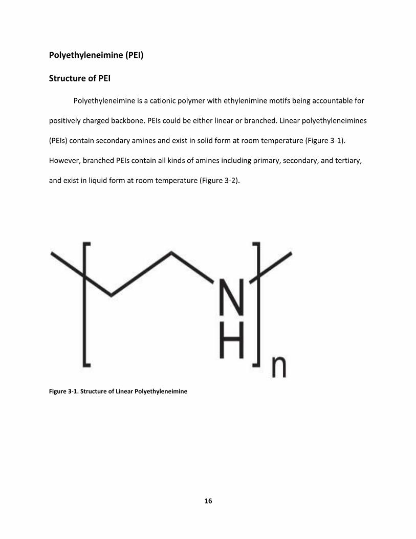
Polyethyleneimine (PEI)
Structure of PEI
Polyethyleneimine is a cationic polymer with ethylenimine motifs being accountable for
positively charged backbone. PEIs could be either linear or branched. Linear polyethyleneimines
(PEIs) contain secondary amines and exist in solid form at room temperature (Figure 3-1).
However, branched PEIs contain all kinds of amines including primary, secondary, and tertiary,
and exist in liquid form at room temperature (Figure 3-2).
Figure 3-1. Structure of Linear Polyethyleneimine

17
Figure 3-2. Structure of Branched Polyehyleneimine
Applications of PEI
One of the applications of PEIs is in gene delivery. This method takes advantage of the
fact that PEI is positively charged. PEI condenses DNA and forms a DNA complex which can be
taken up by cells (endocytosis). Endocytosis occurs because the surface of cell is negatively
charged and the DNA complex is positively charged. Inside the cell, PEI protonation leads to
osmotic swelling which in turn releases the DNA complex into the cytoplasm. If the DNA
complex is unpacked, then it can enter the nucleus( Figure 3-3)(Lungwitz U., et al., 2005).

18
Figure 3-3. PEI application in gene delivery
One other important function of PEI is in anchoring cells to a surface. Cells attach to PEI
due to ionic interactions that exists between cells and PEI. One of the drawbacks of using PEI is
its cytotoxicity (Kafil,V. and Y. Omidi, 2011). The mechanism by which PEI causes cytoxicity is
not known. However, linear PEIs are less toxic to cells than branched PEIs; branched PEIs have
been shown to damage DNA.

19
In the current study, we speculated that mitochondria can be immobolized on PEI
coated graphene.
Poly-L-lysine (PLL)
Structure of PLL
PLL is a cationic polymer with a molecular structure as shown in figure 3-4.
Figure 3-4. Molecular Structure of Poly-L-lysine
Applications of PLL
PLL is a production of bacterial fermentation and is used as a food preservative. In
biology, PLL is used in targeting tumor cells because it binds to tumor cells with a great affinity
(Jordan, C.E, et al., 1994).
20
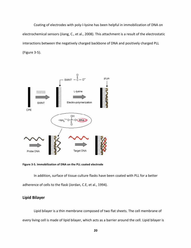
Coating of electrodes with poly-l-lysine has been helpful in immobilization of DNA on
electrochemical sensors (Jiang, C., et al., 2008). This attachment is a result of the electrostatic
interactions between the negatively charged backbone of DNA and positively charged PLL
(Figure 3-5).
Figure 3-5. Immobilization of DNA on the PLL coated electrode
In addition, surface of tissue culture flasks have been coated with PLL for a better
adherence of cells to the flask (Jordan, C.E, et al., 1994).
Lipid Bilayer
Lipid bilayer is a thin membrane composed of two flat sheets. The cell membrane of
every living cell is made of lipid bilayer, which acts as a barrier around the cell. Lipid bilayer is
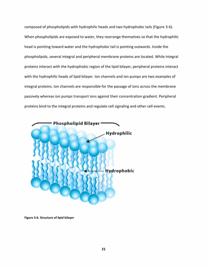
21
composed of phospholipids with hydrophilic heads and two hydrophobic tails (Figure 3-6).
When phospholipids are exposed to water, they rearrange themselves so that the hydrophilic
head is pointing toward water and the hydrophobic tail is pointing outwards. Inside the
phospholipids, several integral and peripheral membrane proteins are located. While integral
proteins interact with the hydrophobic region of the lipid bilayer, peripheral proteins interact
with the hydrophilic heads of lipid bilayer. Ion channels and ion pumps are two examples of
integral proteins. Ion channels are responsible for the passage of ions across the membrane
passively whereas ion pumps transport ions against their concentration gradient. Peripheral
proteins bind to the integral proteins and regulate cell signaling and other cell events.
Figure 3-6. Structure of lipid bilayer

22
Lipid bilayers contain transmembrane ion channel proteins such as gramicidin A (gA)
and α-Hemolysin(α-HL). Lipid bilayers made in the lab are called model bilayers. Commonly
made lipid bilayers are Black lipid membranes (BLM), Supported lipid bilayers (SLB), Tethered
Bilayer Lipid Membranes (t-BLM), and Vesicles (Castellana, E.T., and P. S. Cremer, 2006). In this
study, artificial vesicles, which are called liposomes were used. Liposomes are hollow spheres of
lipids with inner aqueous compartment and outer lipid bilayer (Figure 3-7). Because the
membrane of liposomes is similar to plasma membrane, liposomes can fuse with the plasma
membrane and release their contents. In addition, vesicles are able to fuse with other
organelles inside the cell. One of the widely applications of liposomes is in drug delivery (Riaz,
M., 1996).
Figure 3-7. Structure of an artificial vesicle, liposome

23
Polyethylene glycol (PEG)
Structure of PEG
Polyethylene glycol is a linear neutral polyether, which is also recognized as
polyoxyethylene, polyethylene oxid, and polyoxirane(Figure 3-8).
Figure 3-8. Molecular Structure of PEG
Properties of PEG
Surface coating with PEG reduces cell adhesion and protein adsorption as some studies
have suggested (Alcantar, N. A., A.S. Eray, and J. N. Israelachvili, 2000). The PEG coated surfaces
become hydrophilic and reject proteins. PEG coating also reduces thrombus formation and
tissue damage as platelets will not adhere to the surface of PEG. PEG does not change the
surface chemistry of materials, does not damage cells and active proteins, and is nontoxic.
Proteins are not able to attach to PEG because of the repulsive forces. When a protein
approaches PEG, the available volume for PEG polymer is reduced, thus a repulsive force is

24
generated. At other times, when a protein interpenetrates PEG polymer, a repulsive force is
produced. PEG is biocompatible and soluble in water and other polar solvents. PEG is soluble
in water because it can form hydrogen and oxygen bonds with water molecules (Alcantar, N. A.,
A.S. Eray, and J. N. Israelachvili, 2000).
Applications of PEG
PEG has applications in drug delivery, cell encapsulation, and reducing cell adhesion to a
surface. In drug delivery, PEGylation is an established method of attaching PEG to the drug of
interest (Banerjee, S.S., et al., 2012). PEGylation is known to increase solubility and circulation
time of a hydrophobic drug, and is commonly used for delivering of anti-cancer drugs (Figure 3-
9).
Figure 3-9. PEGylation of drugs to increase solubility

25
CHAPTER 4: MATARIALS AND METHODS
26
Materials
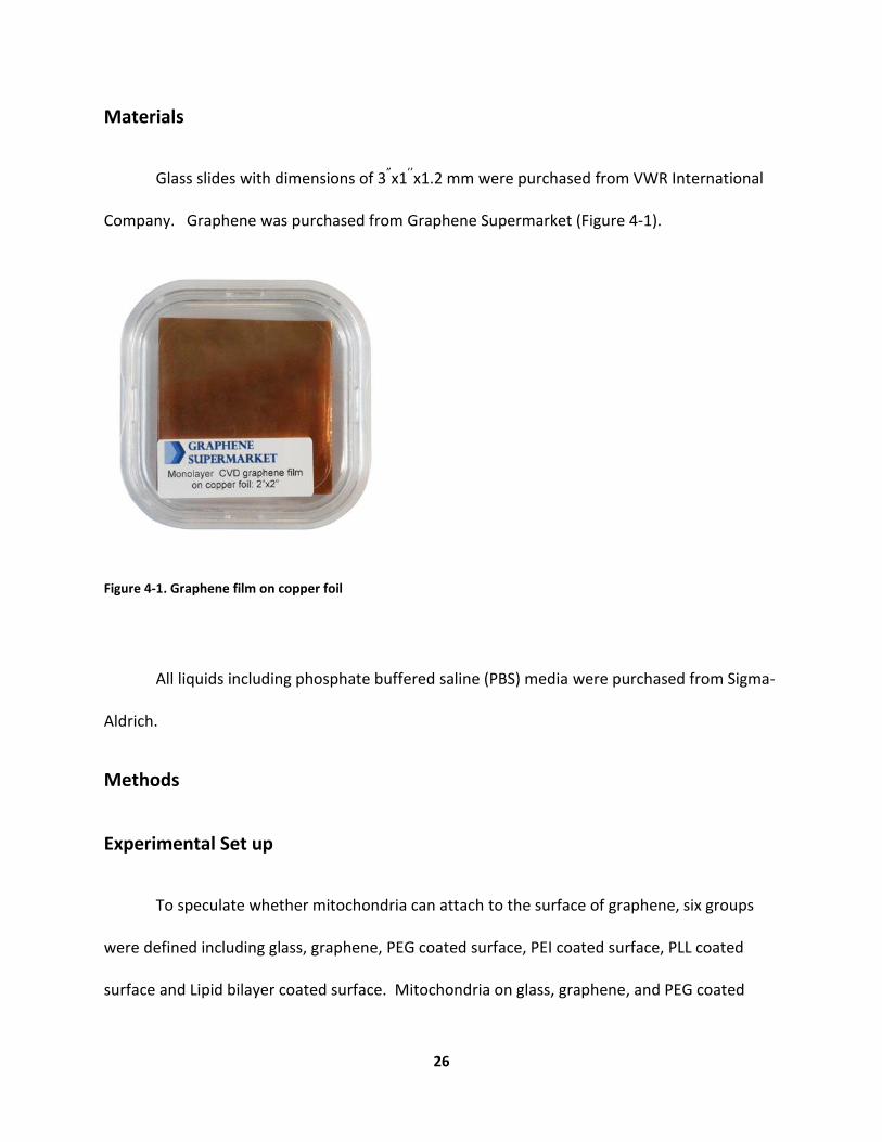
Glass slides with dimensions of 3”x1’’x1.2 mm were purchased from VWR International
Company. Graphene was purchased from Graphene Supermarket (Figure 4-1).
Figure 4-1. Graphene film on copper foil
All liquids including phosphate buffered saline (PBS) media were purchased from Sigma-
Aldrich.
Methods
Experimental Set up
To speculate whether mitochondria can attach to the surface of graphene, six groups
were defined including glass, graphene, PEG coated surface, PEI coated surface, PLL coated
surface and Lipid bilayer coated surface. Mitochondria on glass, graphene, and PEG coated
27
surfaces were expected not to attach. However, mitochondria were anticipated to become
immobilized on PEI, PLL, and lipid bilayer surfaces.
Transfer Method of Graphene film
When graphene was purchased, it was on copper foil. To obtain graphene without
copper, copper had to be etched away. First, the surface of copper-graphene was spin-coated
with Poly-methyl methacrylate (PMMA) in order to protect the surface of graphene. Then,
PMMA was dissolved in chlorobenzene (0.8mg/ml). After the spin coating, the surface was
cured at 190˚C for 1 minute. Second, copper substrate was etched away by ion chloride solution
(0.08g/ml) overnight. Third, the PMMA/graphene film was transferred to De-ionized (DI) water
overnight. Then, PMMA/graphene film was transferred onto the target substrate (glass slide).
After drying the PMMA/graphene film under the vacuum for several hours, the surface was
heated at 180° C in air for 30 minutes. The PMMA surface was removed with an acetone bath
(Li, X., et al., 2009).
Coating of Graphene with PEI and PLL
The surface of graphene was coated with PEI (1:15000 dilutions of 50% W/V solution in
H2O) overnight. Moreover, the surface of graphene was coated with a 0.1% solution of 80,000 -
100,000 Daltons PLL in water.

28
Preparation of Lipid Bilayer
1mM 1, 2-Dioleoyl-sn-glycero-3-phosphocholine (DOPC, unsaturated fatty acid) was
dissolved in chloroform. 1 mM Lissamine Rhodamine Red (LR-DHPE), which is a fluorescence
dye and 1mM gA solution were added to the solution. The solution was mixed at room
temperature for 2 hours. The mixture was then evaporated overnight under a nitrogen stream
to make the lipid suspension for the vesicle fusion. The dried lipid bilayer was rehydrated,
stirred, and sonicated in 10mM phosphate buffered saline solution (PBS) at 55˚C for 1 hour to
make small unilamellar vesicles (SUVs). Finally, the suspension was filtered with a 0.2μm nylon
filter to obtain homogenous SUVs. The surface of graphene was coated with 20μl of lipid
bilayer and was placed inside the oven for 4 hours at 60° C. The surface was slowly cooled down
to room temperature over 20 minutes and was rinsed with DI water.
PDMS Preparation
A few drops of sigma cote were poured on top of the wafer in order to make the PDMS
peeling easier. Silicone elastomer base were mixed thoroughly with curing agent (10:1 dilution)
and the mixture was degassed for 20-30min. PDMS was then poured on top of the wafer and it
was placed inside the oven (60˚C- 70˚C).
Channel Preparation
In order to determine where to look under the microscope, PDMS was cut into small
squares and inside each square, a small hole was created. These channels were then placed on
29
top of clean glass slides. The glass slides were cleaned with 70% ethanol and then DI water, and
air dried before placing PDMS chambers on top of them.
Preparation of Buffers
Before isolating mitochondria from Hela cells, incomplete H buffer, 5% BSA solution, and
respiration buffer were prepared. Incomplete H buffer was a mixture of 210mM mannitol,
70mM sucrose, 1mM EGTA, and 5mM HEPES. PH of the solution was adjusted to 7.2 by adding
enough KOH. The incomplete H bufferwas mixed with 5% BSA solution to make a complete H
buffer (10:1 dilution).
The respiration buffer was made of 225mM mannitol, 75mM sucrose, 10mM KCl, 10mM Tris-
HCl, and 5mM KH2PO4. Afterwards, the PH of the solution was adjusted to 7.2 by adding
enough KOH.
Isolation of Mitochondria
Hela cells were seeded on a tissue flask 3 days before isolation. On the day of isolation,
cells were washed with PBS and then trypsinized with 3ml of trypsin. 4ml of growth media was
added to the mixture of cells/trypsin and was centrifuged at 3000 rpm (850xg) for two minutes.
The pellet was resuspended in growth media and was centrifuged again for 2 min and the
supernatant was discarded. This process was repeated, and the pellet was rinsed with
ethanol/DI water and the homogenizer was pre-chilled on ice. From this point on, every step
was done on ice. The pellet was resuspended in 1ml H-buffer. The resuspension was transferred
to Dounce Tissue Grinder. The cells were homogenized on ice with 15-20 passes. The cells were

30
resuspended in 2ml H-buffer. The mixture was centrifuged at 800xg for 5 minutes. The
supernatant was removed. The pellet was again resuspended in 2ml of H-buffer and was
transferred back to Dounce Tissue Grinder. The cells were disrupted with 10 passes, were
resuspended with 2ml of H-buffer, and were centrifuged for 5 minutes at 4˚C at the speed of
800xg twice. The supernatant was then transferred to a new tube and was centrifuged again at
10,000xg (10,300rpm) for 20 minutes at 4˚C. 1ml of incomplete buffer was added to the pellet
and the mixture was centrifuged for 15 minutes at 4˚C at 10,000xg (10,300rpm). Finally,
mitochondria were resuspended in 2ml of respiration buffer. The concentration of
mitochondria was calculated to be around 100µg/ml.
JC-1 Preparation
JC-1 kit from Sigma Aldrich was used for staining. The content of JC-1 vial was dissolved
in 25µl of DMSO and was mixed vigorously. Then, JC-1 was diluted 5-folds with DMSO to obtain
a concentration of 0.2 µg/ml. JC-1 solution was kept on ice before addition of mitochondria.
TMRM Preparation
TMRM kit was purchased from Sigma-Aldrich. The content of stock vial was mixed with
100µl of DMSO. The stock solution was then diluted with 1X PBS, or cell media to achieve a
10µM concentration. Enough mitochondria in media was added to the TMRM dye to achieve a
concentration of 20-200nM. Mitochondria were then incubated for 15-20 minutes at 37° C in
dark.

31
Imaging of Mitochondria
20 µl of mitochondria was added to each of the six group (glass, graphene, PEG coated
surface, PEI coated Surface, PLL coated surface, Lipid bilayer coated surface). They were
incubated for 30 minutes. Then, two methods of washing were implemented. In the first
method, after staining with JC-1 dye, the chambers were washed by pouring DI water on top of
chamber. In the second method, the content of each chamber was pipetted out. Each chamber
was washed gently by DI water using a pipette. Images were taken using a fluorescence
microscope to assure that the mitochondria were still present.

32
CHAPTER 5: RESULTS
33
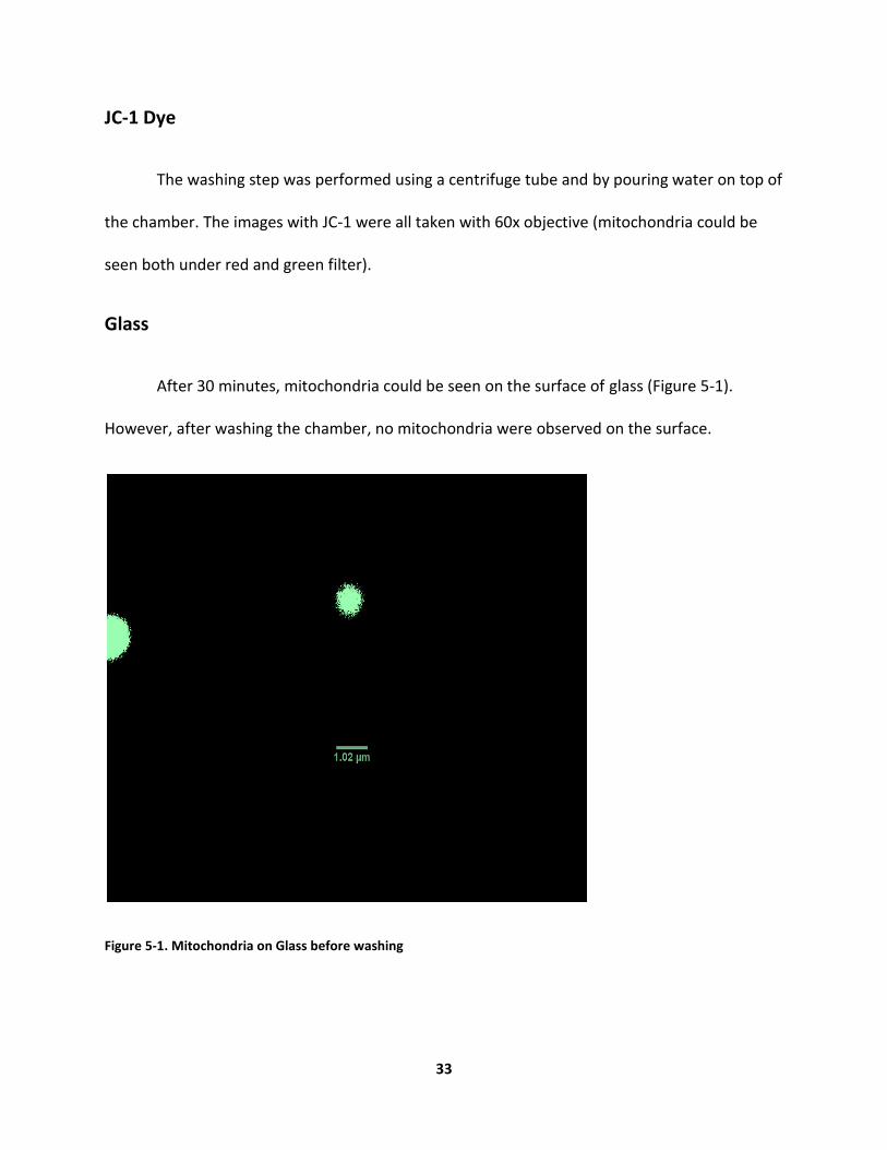
JC-1 Dye
The washing step was performed using a centrifuge tube and by pouring water on top of
the chamber. The images with JC-1 were all taken with 60x objective (mitochondria could be
seen both under red and green filter).
Glass
After 30 minutes, mitochondria could be seen on the surface of glass (Figure 5-1).
However, after washing the chamber, no mitochondria were observed on the surface.
Figure 5-1. Mitochondria on Glass before washing
34
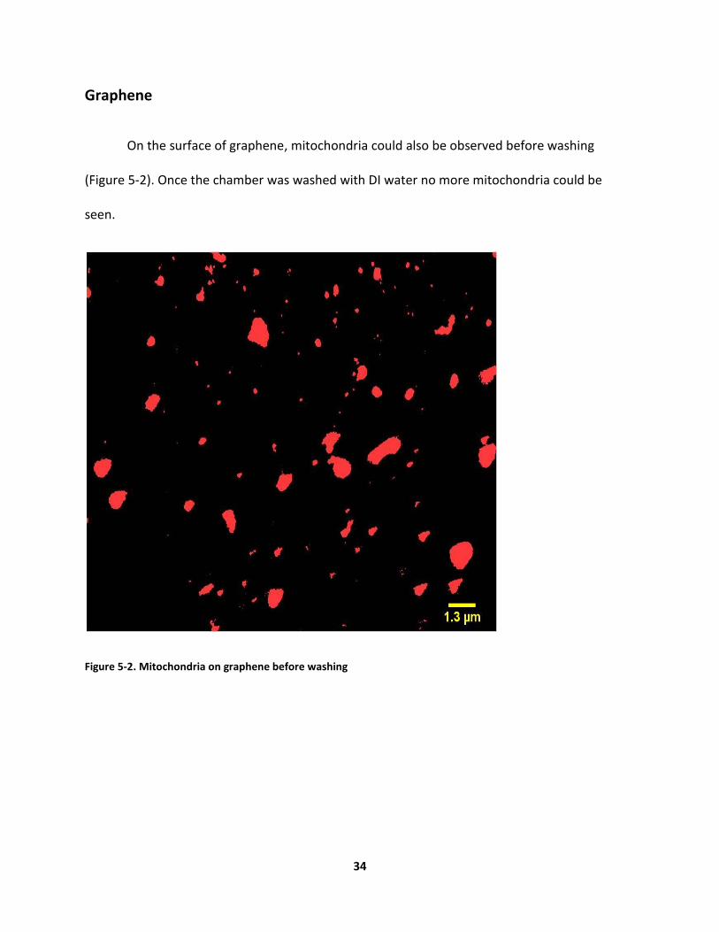
Graphene
On the surface of graphene, mitochondria could also be observed before washing
(Figure 5-2). Once the chamber was washed with DI water no more mitochondria could be
seen.
Figure 5-2. Mitochondria on graphene before washing
35
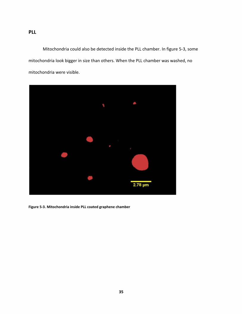
PLL
Mitochondria could also be detected inside the PLL chamber. In figure 5-3, some
mitochondria look bigger in size than others. When the PLL chamber was washed, no
mitochondria were visible.
Figure 5-3. Mitochondria inside PLL coated graphene chamber

36
Lipid bilayer
The surface of graphene coated with lipid bilayer is depicted below (Figure 5-4).
Figure 5-4. Lipid Bilayer on top of glass before addition of mitochondria
Figure 5-5 is an image of mitochondria before washing the chamber. After the wash, no
mitochondria were present.
Figure 5-5. Mitochondria on Lipid bilayer coated graphene

37
PEG
Before washing the PEG chamber, there were some mitochondria present (Figure 5-6).
On the other hand, after washing the chamber, mitochondria were absent.
Figure 5-6. Mitochondria inside PEG coated graphene chamber before washing
38
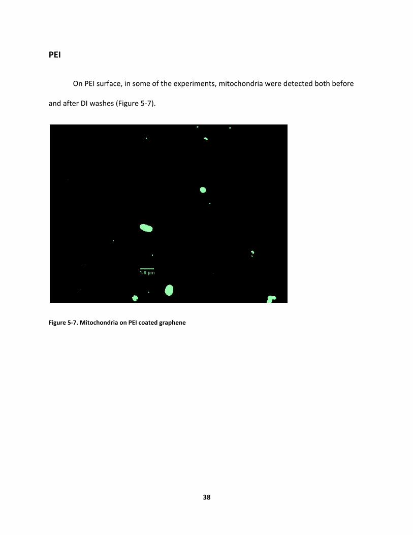
PEI
On PEI surface, in some of the experiments, mitochondria were detected both before
and after DI washes (Figure 5-7).
Figure 5-7. Mitochondria on PEI coated graphene

39
TMRM Dye
The images with TMRM dye were all taken with 40x objective. The washing was done
with a pipette. This experiment was only performed once with the TMRM dye and with this
method of washing.
Glass
Mitochondria could be seen inside the glass chamber before washing, but not
afterwards (Figure 5-8).
Figure 5-8. Mitochondria inside the glass chamber before washing

40
Graphene
Inside the graphene chamber, mitochondria were visible before washing (Figure 5-9).
However, after washing, it seemed like there were no more mitochondria inside the graphene
chamber.
Figure 5-9. Mitochondria inside the graphene chamber before washing
41
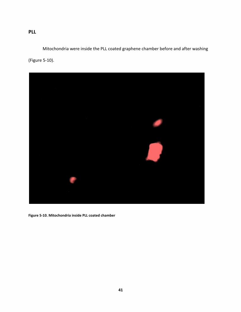
PLL
Mitochondria were inside the PLL coated graphene chamber before and after washing
(Figure 5-10).
Figure 5-10. Mitochondria inside PLL coated chamber

42
Lipid Bilayer
Inside the chamber with coated lipid bilayer, mitochondria were visible both before and
after the washing step (Figure 5-11).
Figure 5-11. Mitochondria inside lipid bilayer coated chamber before and after washing
43
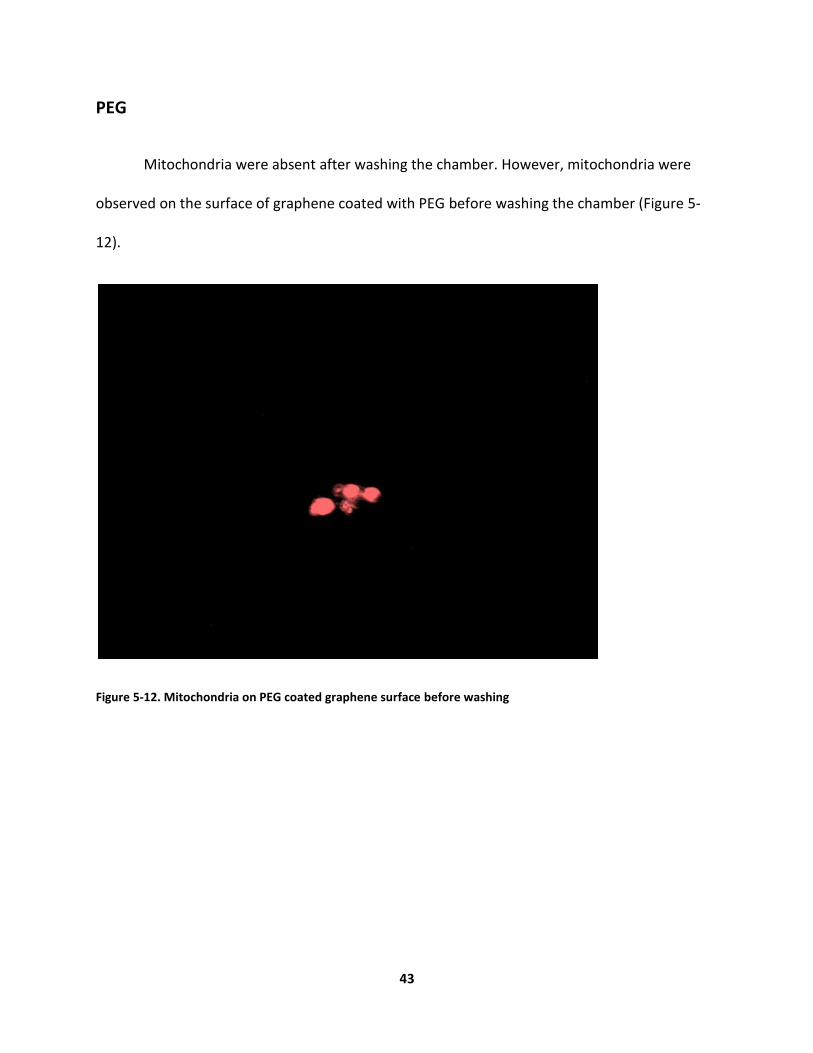
PEG
Mitochondria were absent after washing the chamber. However, mitochondria were
observed on the surface of graphene coated with PEG before washing the chamber (Figure 5-
12).
Figure 5-12. Mitochondria on PEG coated graphene surface before washing

44
PEI
Finally, the images of mitochondria inside the chamber coated with PEI indicated that
there were mitochondria before and after washing with DI water (Figure 5-13).
Figure 5-13. Mitochondria inside PEI coated graphene surface
The summary of the results for the JC-1 dye are presented in Table 1.
Table 5-1 Results of immobilization of mitochondria on graphene with Jc-1 dye
Groups Glass Graphene PEI PLL Lipid
bilayer
PEG
Adhesion of
mitochondria
NO NO YES NO NO NO

45
The summary of the results for the TMRM dye are presented in Table 2.
Table 5-2 Results of immobilization of mitochondria on graphene with TMRM dye
Groups Glass Graphene PEI PLL Lipid
bilayer
PEG on
Graphene
Adhesion of
mitochondria
NO NO YES YES YES NO

46
CHAPTER 6: DISCUSSION AND CONCLUSION
47
Discussion
In the current experiment, six groups were defined to study the immobilization of
mitochondria on graphene. Mitochondria were expected not to adhere to the surface of three
of the groups including glass, graphene, and PEG coated graphene. As discussed before, studies
have shown that the surface of mitochondria is more hydrophobic than hydrophilic and it is
more negatively charged (Whiting, C.E., and A. Edgar., 2006). Since PEG has a hydrophilic
surface and is not positively charged, mitochondria would not be able to attach to its surface.
The surface structure of graphene is very inert for mitochondria to attach to it; graphene is not
charged and contains carbon bonds. As studies have suggested, the surface of glass needs to be
functionalized in order for mitochondria to adhere to it (REERS, M., R. A. KELLY and T. W.
SMITH, 1989).
Mitochondria are assumed to bind to PEI, PLL, and lipid bilayer coated graphene
surfaces. PEI and PLL are both positively charged polymers that have been used in numerous
biological studies. Both PEI and PLL have great affinities for cells. Thus, if the surfaces of these
two polymers attract cells, they should be able to attract mitochondria as well - since both cells
and mitochondria have similar membrane structures. By coating the surface of graphene with
lipid bilayers, it is speculated that mitochondria would attach to graphene due to the similarity
of the surfaces (the surface of mitochondria is also composed of phospholipids).
In the experiment done with JC-1 dye, mitochondria were seen to be only immobilized
on the PEI surface. However, with TMRM dye, the experiment was only performed once and
mitochondria seemed to be bound to PEI, PLL, and lipid bilayer coated graphene surfaces.

48
Therefore, JC-1 dye might have influenced the results. JC-1 dye has some disadvantages over
other dyes as mentioned before. Some of the drawbacks of JC-1 dye include its sensitivity to the
concentration of loading and the time of loading. In addition, JC-1 dye has been known for not
being specific in staining of mitochondria. In the studies of immobilization of mitochondria
done by other groups, JC-1 dye has never been used for staining.
One might argue that in some images the size of mitochondria were larger than what it
should be. One possibility is that the solution of mitochondria was not mixed enough and
consequently, clumps of mitochondria were observed under the microscope.
Repeating the experiment with the TMRM dye, which has been demonstrated to be a
more effective dye, the results were different. With TMRM dye, the results were as expected;
mitochondria were immobilized on PEI, PLL, and lipid bilayer coated surfaces. As others have
reported, mitochondria were attached to the surfaces of PEI and PLL coated glasses
(Kuzmenko,A., S. Tankov, B. P. English, et al., 2011). However, there were some distinctions
between our method and others, specifically in the washing step. Some groups have washed
the mitochondria with KCl and some others with buffer B (Quarato, G., et al., 2011).
Furthermore, some have placed the mitochondria inside a perfusion chamber, which might be a
better environment for mitochondria (Vergun, O., T. V. Votyakova, and I. J. Reynolds, 2003).
Besides, not all groups have mentioned the specifics of their washing method. In another
report, buffer B was gently withdrawn to remove any unattached mitochondria (Quarato, G., et
al., 2011). In our experiment, with the TMRM dye, gentle washing was done using a pipette.
With JC-1 dye, the method of washing was a harsher method. Thus, the method of washing
49
could have had an effect on immobilization of mitochondria. To improve the results of this
study, more experiments should be done with the TMRM dye. Besides, the unbound
mitochondria should be washed away with KCl instead of DI water to compare the results.
Conclusion
In summary, the washing technique as well as the staining method seemed to have
significant influences on immobilization of mitochondria on graphene. With JC-1 dye and the
harsh washing method, the anticipated results were not achieved. However, with the TMRM
dye and gentle washing, the results were as expected. More experiments should be done with
the TMRM dye to find out the validity of these results.

50
REFERENCES
Alberts, B.,et al. Molecular Biology of the Cell. New York:Garland Science: The Mitochondrion,
2002.
Alcantar, N. A., A.S. Eray, and J. N. Israelachvili. "Polyethylene glycol–coated biocompatible
surfaces." John Wiley & Sons, Inc. (2000): 344-345.
Banerjee, S.S., et al. "Poly(ethylene glycol)-Prodrug Conjugates:Concept, Design, and
Applications." Journal of Drug Delivery (2012): 2-4.
Castellana, E.T., and P. S. Cremer. "Solid supported lipid bilayers: From biophysical studies to
sensor design." Surface Science Reports (2006): 429-444.
Choi, W.et al. "Synthesis of Graphene and Its applications:A review." Critical Reviews in Solid
State and Materials Sciences (2010): 35:1, 52-71.
Dale, A. C.et al. "Graphene electrochemistry: an overview of potential applications." Analyst
(2010): 135, 2768–2778.
Desler C., et al. "The importance of Mitochondrial DNA in aging and Cancer." Journal of Aging
Research (2011): 1-2.
Gottlieb E., et al. "Mitochondrial membrane potential regulates matrix configuration and
cytochrome c release during apoptosis." Cell Death and Differentiation (2003): 10, 709–717.
Jiang, C., et al. "A DNA electrochemical sensor with poly-l-lysine/single-walled carbon
nanotubes films and its application for the highly sensitive EIS detection of PAT gene fragment
and PCR amplification of NOS gene." Electrochimica Acta (53 (2008) ): 2917–2924.
Jordan, C.E, et al. "Characterization of Poly-L-lysine Adsorption onto Alkanethiol-Modified Gold
Surfaces with Polarization-Modulation Fourier Transform Infrared Spectroscopy and Surface
Plasmon Resonance Measurements." Langmuir (1994): 3642-3648.
Kafil, V. and Y. Omidi. "Cytotoxic Impacts of Linear and Branched Polyethylenimine
Nanostructures in A431 Cells." BioImpacts (2011): 23-30.
51
Kauffman, D.R., and A. Star. "Graphene versus Carbon Nanotubes for Chemical Sensor and Fuel
Cell Applications." Analyst (2010): 135, 2790-2797.
Kuzmenko, A., S. Tankov, B. P. English, et al. "Single molecule tracking fluorescence microscopy
in mitochondria reveals highly dynamic but confined movement of Tom40." Scientific Reports
(2011): 5-6.
Li, X., et al. "Large-Area Synthesis of High-Quality and Uniform Graphene Films on Copper Foils."
Science (2009): 1312-1314.
Lim, T. ON-CHIP MITOCHONDRIAL ASSAY MICROFLUIDIC DEVICES AND PROTEIN
NANOPORE/NANOTUBE HYBRID TRANSISTOR. Irvine, 2011.
Lungwitz U., et al. "Polyethylenimine-based non-viral gene delivery systems." European Journal
of Pharmaceutics and Biopharmaceutics (60 (2005)): 247–266.
Perry, S.W., et al. "Mitochondrial membrane potential probes and the proton gradient: a
practical usage guide." BioTechniques (2011): 98-115.
Poot, M., et al. "Analysis of Mitochondrial Morphology and Function with." Histochemistry and
Cytochemistry (1996): 1363-1372.
Quarato, G.,et al. "Functional imaging of membrane potential at the single mitochondrion
level:Possible application for diagnosis of human diseases." Mitochondrion (2011): 764–773.
REERS, M., R. A. KELLY and T. W. SMITH. "Calcium and proton activities in rat cardiac
mitochondria." Biochem. J (1989): 257, 131-142.
Riaz, M. "LIPOSOMES PREPARATION METHODS." Pakistan Journal of Pharmaceutical Sciences
(1996): 65-77.
Rogers, G. W, et al. "High Throughput Miccroplate Respiratory Measurements Using Minimal
Quantities of Isolated Mitochondria." PLoS ONE (2011): 21746.
Schulz, G.E. "b-Barrel membrane proteins." Current Opinion in Structural Biology (2000):
10:443-447.
Vergun, O., T. V. Votyakova, and I. J. Reynolds. "Spontaneous Changes in Mitochondrial
Membrane Potential." Biophysical Journal (2003): 3358–3366.
Whiting, C. E., and A. Edgar. "CE-LIF analysis of mitochondria using uncoated and dynamically
coated capillaries." Electrophoresis (2006): 27,4523-4531.