routing protocols and concepts40p6zu91z1c3x7lz71846qd1-wpengine.netdna-ssl.com/... · routing...
TRANSCRIPT

Routing Protocols and ConceptsCCNA Exploration Labs and Study Guide
Instructor Edition
Allan Johnson
Cisco Press800 East 96th Street
Indianapolis, Indiana 46240 USA
ii Routing Protocols and Concepts, CCNA Exploration Labs and Study Guide
Routing Protocols and ConceptsCCNA Exploration Labs and Study GuideInstructor Edition
Allan Johnson
Copyright© 2008 Cisco Systems, Inc.
Published by:Cisco Press800 East 96th Street Indianapolis, IN 46240 USA
All rights reserved. No part of this book may be reproduced or transmitted in any form or by anymeans, electronic or mechanical, including photocopying, recording, or by any information storageand retrieval system, without written permission from the publisher, except for the inclusion ofbrief quotations in a review.
ISBN-13: 978-1-58705-575-1
ISBN-10: 1-58705-575-9
Warning and DisclaimerThis book is designed to provide information about Routing Protocols and Concepts of the CiscoNetwork Academy CCNA Exploration curriculum. Every effort has been made to make this bookas complete and as accurate as possible, but no warranty or fitness is implied.
The information is provided on an “as is” basis. The authors, Cisco Press, and Cisco Systems, Inc.shall have neither liability nor responsibility to any person or entity with respect to any loss ordamages arising from the information contained in this book or from the use of the discs or programsthat may accompany it.
The opinions expressed in this book belong to the author and are not necessarily those of CiscoSystems, Inc.
Trademark AcknowledgmentsAll terms mentioned in this book that are known to be trademarks or service marks have beenappropriately capitalized. Cisco Press or Cisco Systems, Inc. cannot attest to the accuracy of thisinformation. Use of a term in this book should not be regarded as affecting the validity of anytrademark or service mark.
Corporate and Government SalesThe publisher offers excellent discounts on this book when ordered in quantity for bulk purchasesor special sales, which may include electronic versions and/or custom covers and content particularto your business, training goals, marketing focus, and branding interests. For more information,please contact: U.S. Corporate and Government Sales [email protected]
For sales outside the United States please contact: International Sales [email protected]
PublisherPaul Boger
Associate PublisherDave Dusthimer
Cisco RepresentativeAnthony Wolfenden
Cisco Press Program ManagerJeff Brady
Executive EditorMary Beth Ray
Production ManagerPatrick Kanouse
Senior Development EditorChristopher Cleveland
Senior Project EditorSan Dee Phillips
Copy EditorJohn Edwards
Technical EditorTony Chen
Editorial AssistantVanessa Evans
Book and Cover DesignerLouisa Adair
CompositionLouisa Adair
Multimedia DeveloperDan Scherf
ProofreaderSheri Cain

Feedback InformationAt Cisco Press, our goal is to create in-depth technical books of the highest quality and value. Eachbook is crafted with care and precision, undergoing rigorous development that involves the uniqueexpertise of members from the professional technical community.
Readers’ feedback is a natural continuation of this process. If you have any comments regarding howwe could improve the quality of this book, or otherwise alter it to better suit your needs, you can con-tact us through e-mail at [email protected]. Please make sure to include the book title andISBN in your message.
We greatly appreciate your assistance.
iii

About the AuthorAllan Johnson entered the academic world in 1999 after 10 years as a business owner/operator todedicate his efforts to his passion for teaching. He holds both an M.B.A. and an M.Ed. in occupationaltraining and development. He is an information technology instructor at Del Mar College in CorpusChristi, Texas. In 2003, Allan began to commit much of his time and energy to the CCNAInstructional Support Team, providing services to Networking Academy instructors worldwide andcreating training materials. He now works full time for the Academy in Learning SystemsDevelopment.
iv Routing Protocols and Concepts, CCNA Exploration Labs and Study Guide

About the Technical ReviewerTony Chen, CCNP and CCAI, manages Cisco Networking Academy for the College of DuPage inGlen Ellyn, Illinois, and teaches CCNA and CCNP classes at the college. As a manager for regionalacademy, he also trains and supports local Cisco networking academies. He also manages the comput-er network for the Ball Foundation. The Ball Foundation’s motto is to discover and develop humanpotential. Tony Chen has a understanding wife, Joanne, and one wonderful daughter, Kylie.
v
DedicationsFor my wife, Becky. Without the sacrifices you made during the project, this work would not havecome to fruition. Thank you providing me the comfort and resting place only you can give.
—Allan Johnson
vi Routing Protocols and Concepts, CCNA Exploration Labs and Study Guide

AcknowledgmentsAs technical editor, Tony Chen served admirably as my second pair of eyes, finding and correctingtechnical inaccuracies as well as grammatical errors. Tony’s meticulous attention to detail helped tomake this project a first-class production.
Mary Beth Ray, executive editor, you amaze me with your ability to juggle multiple projects at once,steering each from beginning to end. I can always count on you to make the tough decisions.
This is my third project with Christopher Cleveland as development editor. His dedication to perfec-tion pays dividends in countless, unseen ways. Thank you again, Chris, for providing me with much-needed guidance and support. This book could not be a reality without your persistence.
Last, I cannot forget to thank all my students—past and present—who have helped me over the yearsto create engaging and exciting activities and labs. There is no better way to test the effectiveness ofan activity or lab than to give it to a team of dedicated students. They excel at finding the obscurest oferrors! I could have never done this without all your support.
vii
Contents at a Glance
Introduction xxv
Chapter 1 Introduction to Routing and Packet Forwarding 1
Chapter 2 Static Routing 69
Chapter 3 Introduction to Dynamic Routing Protocols 139
Chapter 4 Distance Vector Routing Protocols 169
Chapter 5 RIP Version 1 189
Chapter 6 VLSM and CIDR 245
Chapter 7 RIPv2 307
Chapter 8 The Routing Table: A Closer Look 357
Chapter 9 EIGRP 393
Chapter 10 Link-State Routing Protocols 474
Chapter 11 OSPF 495
viii Routing Protocols and Concepts, CCNA Exploration Labs and Study Guide

ContentsIntroduction xxv
Chapter 1 Introduction to Routing and Packet Forwarding 1
Study Guide 2
Inside the Router 2
Vocabulary Exercise: Matching 2
Vocabulary Exercise: Completion 4
Label the External Components of a Router Exercise 6
Label the Internal Components of a Router Exercise 7
Describe the Internal Components of a Router Exercise 8
Router Bootup Process Exercise 10
Interpreting the show version Command Exercise 10
CLI Configuration and Addressing 11
Implementing Basic Addressing Schemes Exercise 11
Basic Router Configuration Exercise 12
Packet Tracer Exercise 1-1: Basic Router Configuration 15
Task 1: Add Devices and Connect Cables 15
Task 2: Configure PCs 15
Task 3: Configure R1 16
Task 4: Configure R2 16
Task 5: Save the Packet Tracer File 17
Building the Routing Table 17
Vocabulary Exercise: Completion 17
Routing Table Principles Exercise 19
Path Determination and Switching Functions 20
Internet Protocol (IP) Packet Format Exercise 20
MAC Layer Frame Format Exercise 20
Best Path and Metrics: Completion and Short Answer Exercise 21
Path Determination and Switching Function Exercise 21
Labs and Activities 25
Command Reference 25
Lab 1-1: Cabling a Network and Basic Router Configuration (1.5.1) 26
Task 1: Cable the Ethernet Links of the Network 27
Task 2: Cable the Serial Link Between the R1 and R2 Routers 28
Task 3: Establish a Console Connection to the R1 Router 29
Task 4: Erase and Reload the Routers 29
Task 5: Understand Command-Line Basics 30
Task 6: Perform Basic Configuration of Router R1 33
Task 7: Perform Basic Configuration of Router R2 35
Task 8: Configure IP Addressing on the Host PCs 36
Task 9: Examine Router show Commands 37
ix
Task 10: Use the ping Command 41
Task 11: Use the traceroute Command 42
Task 12: Create a start.txt File 43
Task 13: Load the start.txt File onto the R1 Router 45
Packet Tracer Companion 46
Appendix 1A: Installing and Configuring Tera Term for Use in Windows XP 47
Appendix 1B: Configuring Tera Term as the Default Telnet Client in Windows XP 48
Appendix 1C: Accessing and Configuring HyperTerminal 51
Lab 1-2: Basic Router Configuration (1.5.2) 52
Task 1: Cable the Network 53
Task 2: Erase and Reload the Routers 54
Task 3: Perform Basic Configuration of Router R1 55
Task 4: Perform Basic Configuration of Router R2 57
Task 5: Configure IP Addressing on the Host PCs 58
Task 6: Verify and Test the Configurations 58
Task 7: Reflection 60
Task 8: Documentation 61
Task 9: Clean Up 61
Packet Tracer Companion 61
Lab 1-3: Challenge Router Configuration (1.5.3) 61
Task 1: Subnet the Address Space 62
Task 2: Determine Interface Addresses 62
Task 3: Prepare the Network 63
Task 4: Perform Basic Router Configurations 63
Task 5: Configure and Activate Serial and Ethernet Addresses 63
Task 6: Verify the Configurations 64
Task 7: Reflection 64
Task 8: Document the Router Configurations 64
Packet Tracer Companion 65
Packet Tracer Skills Integration Challenge 65
Task 1: Design and Document an Addressing Scheme 66
Task 2: Cable Devices 66
Task 3: Apply a Basic Configuration 67
Task 4: Identify Layer 2 and Layer 3 Addresses Used to Switch Packets 67
Reflection 67
End Notes 68
Chapter 2 Static Routing 69
Study Guide 70
Routers and the Network 70
Document the Addressing Scheme 70
Packet Tracer Exercise 2-1 71
x Routing Protocols and Concepts, CCNA Exploration Labs and Study Guide

Router Configuration Review 72
show Commands Matching Exercise 72
Configuring and Verifying Interfaces Exercise 73
Exploring Directly Connected Networks 75
Directly Connected Networks Exercise 75
Packet Tracer Exercise 2-1: Task 3—Basic Router Configuration 78
Cisco Discovery Protocol Exercise 78
Packet Tracer Exercise 2-1: Task 4—Configure CDP 80
Static Routes with Next-Hop Addresses 80
Static Route Command Syntax Exercise 81
Static Routes with Next-Hop Address Exercise 81
Packet Tracer Exercise 2-1 83
Configuring a Static Route with an Exit Interface 84
Static Routes with an Exit Interface Exercise 84
Packet Tracer Exercise 2-2 85
Summary and Default Static Routes 86
Calculating Summary Route Exercises 86
Combining Static Routes into Summary Routes Exercise 91
Packet Tracer Exercise 2-3: Summary Route Configuration 93
Configuring Default Static Routes Exercise 94
Packet Tracer Exercise 2-4: Default Route Configuration 95
Managing and Troubleshooting Static Routes 96
Troubleshooting a Missing Route 96
Labs and Activities 97
Command Reference 97
Lab 2-1: Basic Static Route Configuration (2.8.1) 98
Task 1: Cable, Erase, and Reload the Routers 99
Task 2: Perform Basic Router Configuration 99
Task 3: Interpreting Debug Output 101
Task 4: Finish Configuring Router Interfaces 106
Task 5: Configure IP Addressing on the Host PCs 106
Task 6: Test and Verify the Configurations 106
Task 7: Gather Information 107
Task 8: Configure a Static Route Using a Next-Hop Address 109
Task 9: Configure a Static Route Using an Exit Interface 111
Task 10: Configure a Default Static Route 113
Task 11: Configure a Summary Static Route 114
Task 12: Summary, Reflection, and Documentation 116
Task 13: Clean Up 117
Task 14: Challenge 117
Packet Tracer Companion: Basic Static Route Configuration (2.8.1) 118
xi

Lab 2-2: Challenge Static Route Configuration (2.8.2) 118
Task 1: Subnet the Address Space 119
Task 2: Determine Interface Addresses 120
Task 3: Prepare the Network 121
Task 4: Perform Basic Router Configurations 121
Task 5: Configure and Activate Serial and Ethernet Addresses 121
Task 6: Verify Connectivity to Next-Hop Device 121
Task 7: Configure Static Routing on BRANCH 122
Task 8: Configure Static Routing on HQ 123
Task 9: Configure Static Routing on ISP 124
Task 10: Verify the Configurations 124
Task 11: Reflection 125
Task 12: Document the Router Configurations 125
Task 13: Clean Up 125
Packet Tracer Companion: Challenge Static Route Configuration (2.8.2) 125
Lab 2-3: Troubleshooting Static Routes (2.8.3) 125
Task 1: Cable, Erase, and Reload the Routers 127
Task 2: Load Routers with the Supplied Scripts 127
Task 3: Troubleshoot the BRANCH Router 131
Task 4: Troubleshoot the HQ Router 133
Task 5: Troubleshoot the ISP Router 134
Task 6: Reflection 135
Task 7: Documentation 135
Packet Tracer Companion: Troubleshooting Static Routes (2.8.3) 136
Packet Tracer Skills Integration Challenge 136
Introduction 136
Task 1: Cable the Devices 137
Task 2: Apply a Basic Configuration 137
Task 3: Configure Static and Default Routing 137
Task 4: Test Connectivity and Examine the Configuration 137
End Notes 137
Chapter 3 Introduction to Dynamic Routing Protocols 139
Study Guide 140
Introduction and Advantages 140
Routing Protocols Evolution and Classification Exercise 140
Vocabulary Exercise: Matching (Key Words) 141
Dynamic Routing Protocol Concepts Exercise 142
Dynamic Versus Static Routing Exercise 143
Classifying Dynamic Routing Protocols 143
Dynamic Routing Protocols Classification Chart 144
Dynamic Routing Protocols Classification Exercise 144
xii Routing Protocols and Concepts, CCNA Exploration Labs and Study Guide

Metrics 146
Metric Parameters Exercise 146
Administrative Distances 147
Concept of Administrative Distance Exercise 147
Routing Sources and Administrative Distance Exercise 148
Identifying Elements of the Routing Table Exercise 148
Labs and Activities 150
Command Reference 150
Lab 3-1: Subnetting Scenario 1 (3.5.2) 150
Task 1: Examine the Network Requirements 152
Task 2: Design an IP Addressing Scheme 152
Task 3: Assign IP Addresses to the Network Devices 153
Task 4: Test the Network Design 153
Task 5: Reflection 154
Lab 3-2: Subnetting Scenario 2 (3.5.3) 154
Task 1: Examine the Network Requirements 157
Task 2: Design an IP Addressing Scheme 157
Task 3: Assign IP Addresses to the Network Devices 158
Task 4: Test the Network Design 160
Task 5: Reflection 160
Lab 3-3: Subnetting Scenario 3 (3.5.4) 161
Task 1: Examine the Network Requirements 163
Task 2: Design an IP Addressing Scheme 163
Task 3: Reflection 163
Packet Tracer Skills Integration Challenge 164
Introduction 164
Task 1: Design and Document an Addressing Scheme 165
Task 2: Apply a Basic Configuration 166
Task 3: Configure Static and Default Routing 166
Task 4: Test Connectivity and Examine the Configuration 166
Chapter 4 Distance Vector Routing Protocols 169
Study Guide 170
Introduction to Distance Vector Routing Protocols 170
Distance Vector Protocols Concepts Exercise 170
Routing Protocols Characteristics Exercise 171
Comparing Routing Protocol Characteristics Exercise 172
Network Discovery 172
Network Discovery Exercise 172
Routing Table Maintenance 174
Distance Vector Table Maintenance Techniques Exercise 174
Routing Loops 176
Routing Loop Concepts Exercise 176
xiii

Distance Vector Routing Protocols Today 178
Comparing Distance Vector Routing Protocols 178
Labs and Activities 179
Lab 4-1: Routing Table Interpretation (4.6.1) 179
Task 1: Examine the Router Output 179
Task 2: Create a Diagram of the Network Based on the Router Output 181
Task 3: Create the Network 182
Task 4: Configure the Routing Protocol for Each Router 182
Task 5: Document the Router Configurations 183
Task 6: Clean Up 183
Packet Tracer Companion: Routing Table Interpretation (4.6.1) 183
Packet Tracer Skills Integration Challenge 183
Introduction 183
Task 1: Design and Document an Addressing Scheme 184
Task 2: Apply a Basic Configuration 187
Task 3: Configure Static and Default Routing 187
Task 4: Test Connectivity and Examine the Configuration 187
Chapter 5 RIP Version 1 189
Study Guide 190
RIPv1: Distance Vector, Classful Routing Protocol 190
RIP Concepts Exercise 190
Basic RIPv1 Configuration 192
Document the Addressing Scheme 192
Packet Tracer Exercise 5-1 193
Configuring RIP as the Routing Protocol 194
Packet Tracer Exercise 5-1 (Continued) 195
Verification and Troubleshooting 195
show ip route Command 195
Interpreting show ip route Output 196
show ip protocols Command 196
debug ip rip Command 197
Passive Interfaces 198
Packet Tracer Exercise 5-1 (Continued) 198
Automatic Summarization 199
Automatic Summarization Concepts 199
Automatic Summarization Example 200
Default Routes and RIPv1 201
Default Routing Exercise 201
Packet Tracer Exercise 5-2 202
Labs and Activities 204
xiv Routing Protocols and Concepts, CCNA Exploration Labs and Study Guide

Command Reference 204
Lab 5-1: Basic RIP Configuration (5.6.1) 204
Scenario A: Running RIPv1 on Classful Networks 205
Packet Tracer Companion: Basic RIP Configuration (5.6.1a) 210
Scenario B: Running RIPv1 with Subnets and Between Classful Networks 210
Packet Tracer Companion: Basic RIP Configuration (5.6.1b) 214
Scenario C: Running RIPv1 on a Stub Network 215
Packet Tracer Companion: Basic RIP Configuration (5.6.1c) 218
Lab 5-2: Challenge RIP Configuration (5.6.2) 219
Task 1: Subnet the Address Space 220
Task 2: Determine Interface Addresses 221
Task 3: Prepare the Network 221
Task 4: Perform Basic Router Configurations 221
Task 5: Configure and Activate Serial and Ethernet Addresses 222
Task 6: Verify Connectivity to Next-Hop Device 222
Task 7: Configure RIP Routing on the BRANCH Router 222
Task 8: Configure RIP and Static Routing on the HQ Router 223
Task 9: Configure Static Routing on the ISP Router 223
Task 10: Verify the Configurations 223
Task 11: Reflection 224
Task 12: Document the Router Configurations 224
Task 13: Clean Up 225
Packet Tracer Companion: Challenge RIP Configuration (5.6.2) 225
Lab 5-3: RIP Troubleshooting (5.6.3) 225
Task 1: Cable, Erase, and Reload the Routers 227
Task 2: Load Routers with the Supplied Scripts 227
Task 3: Troubleshoot the BRANCH Router 231
Task 4: Troubleshoot the HQ Router 233
Task 5: Troubleshoot the ISP Router 235
Task 6: Reflection 236
Task 7: Documentation 236
Task 8: Clean Up 237
Packet Tracer Companion: RIP Troubleshooting (5.6.3) 237
Packet Tracer Skills Integration Challenge 237
Introduction 237
Task 1: Design and Document an Addressing Scheme 240
Task 3: Apply a Basic Configuration 242
Task 4: Configure Static Routing Between ISP Routers 242
Task 5: Configure RIPv1 Routing in Region 1 and Region 2 242
Task 6: Disable RIP Updates on Appropriate Interfaces 243
Task 7: Configure Default Routes and Redistribute Through RIP 243
Task 8: Verify Full Connectivity Between All Devices in the Topology 243
xv

Chapter 6 VLSM and CIDR 245
Study Guide 246
Classful and Classless Addressing 246
Move from Classful to Classless Addressing Exercise 246
VLSM 248
VLSM Addressing Design Exercises 248
VLSM Addressing Design Scenarios 251
CIDR 259
Calculating a Summary Route Exercises 259
Labs and Activities 262
Activity 6-1: Basic VLSM Calculation and Addressing Design (6.4.1) 262
Task 1: Examine the Network Requirements 263
Task 2: Design an IP Addressing Scheme 263
Task 3: Assign IP Addresses to the Network Devices 266
Packet Tracer Companion: Basic VLSM Calculation and Addressing Design (6.4.1) 268
Activity 6-2: Challenge VLSM Calculation and Addressing Design (6.4.2) 268
Task 1: Examine the Network Requirements 270
Task 2: Divide the Network into Three Subnetworks 270
Task 3: Design an IP Addressing Scheme for the Central Network 271
Task 4: Design an IP Addressing Scheme for the West Network 272
Task 5: Design an IP Addressing Scheme for the East Network 275
Packet Tracer Companion: Challenge VLSM Calculation and Addressing Design(6.4.2) 280
Activity 6-3: Troubleshooting a VLSM Addressing Design (6.4.3) 280
Task 1: Examine the Addressing for the HQ LANs 281
Task 2: Examine the Addressing for the Branch1 LANs 282
Task 3: Examine the Addressing for the Branch2 LANs 283
Task 4: Examine the Addressing for the Links Between Routers 283
Task 5: Document the Corrected Addressing Information 284
Packet Tracer Companion: Troubleshooting a VLSM Addressing Design (6.4.3) 285
Activity 6-4: Basic Route Summarization (6.4.4) 285
Task 1: Determine the Summary Route for the HQ LANs 286
Task 2: Determine the Summary Route for the EAST LANs 286
Task 3: Determine the Summary Route for the WEST LANs 287
Task 4: Determine the Summary Route for the HQ, EAST, and WEST LANs 287
Packet Tracer Companion: Basic Route Summarization (6.4.4) 287
Activity 6-5: Challenge Route Summarization (6.4.5) 288
Task 1: Determine the Summary Route for the S-WEST LANs 290
Task 2: Determine the Summary Route for the NW-BR1 LANs 290
Task 3: Determine the Summary Route for the NW-BR2 LANs 290
Task 4: Determine the Summary Route for the Northwest Portion of the Network 291
xvi Routing Protocols and Concepts, CCNA Exploration Labs and Study Guide

Task 5: Determine the Summary Route for the West Portion of the Network 291
Task 6: Determine the Summary Route for the Central Portion of the Network 292
Task 7: Determine the Summary Route for the N-EAST LANs 292
Task 8: Determine the Summary Route for the SE-BR1 LANs 292
Task 9: Determine the Summary Route for the SE-BR2 LANs 293
Task 10: Determine the Summary Route for the SE-ST1 LANs 293
Task 11: Determine the Summary Route for the SE-ST2 LANs 293
Task 12: Determine the Summary Route for the Southeast Portion of theNetwork 294
Task 13: Determine the Summary Route for the East Portion of the Network 294
Task 14: Determine the Summary Route for the Entire Network 295
Packet Tracer Companion: Challenge Route Summarization (6.4.5) 295
Activity 6-6: Troubleshooting Route Summarization (6.4.6) 295
Task 1: Examine the Summary Routes on the HQ Router 296
Task 2: Examine the Summary Routes on the WEST Router 297
Task 3: Examine the Summary Routes on the EAST Router 297
Task 4: Examine the Summary Route on the ISP Router 297
Task 5: Document the Corrected Summary Routes 297
Packet Tracer Companion: Troubleshooting Route Summarization (6.4.6) 298
Packet Tracer Skills Integration Challenge: VLSM and CIDR 298
Task 1: Design and Document an Addressing Scheme 301
Task 3: Apply a Basic Configuration 304
Task 4: Configure Static Routing Between ISP Routers 304
Task 5: Configure RIPv2 Routing in Region 1 and Static Routing in Region 2 304
Task 6: Disable RIP Updates on Appropriate Interfaces 304
Task 7: Configure Default Routes and Redistribute Through RIP 304
Task 8: Verify Full Connectivity Between All Devices in the Topology 305
Chapter 7 RIPv2 307
Study Guide 308
RIPv1 Limitations 308
Documenting the Addressing Scheme 308
Packet Tracer Exercise 7-1 310
Dynamic and Static Routing Configuration 311
Packet Tracer Exercise 7-1 312
Concept Questions 312
Configuring RIPv2 314
RIPv2 Message Format 314
RIPv2 Configurations 315
Packet Tracer Exercise 7-1 316
xvii

VLSM and CIDR 316
RIPv2 and VLSM 316
RIPv2 and CIDR 317
Verifying and Troubleshooting RIPv2 317
Verification and Troubleshooting Commands 317
Common RIPv2 Issues 318
Authentication 318
Labs and Activities 319
Command Reference 319
Lab 7-1: RIPv2 Basic Configuration (7.5.1) 319
Task 1: Cable, Erase, and Reload the Routers 320
Task 2: Load Routers with the Supplied Scripts 321
Task 3: Examine the Current Status of the Network 323
Task 4: Configure RIP Version 2 325
Task 5: Examine the Automatic Summarization of Routes 326
Task 6: Disable Automatic Summarization 328
Task 7: Examine the Routing Tables 328
Task 8: Verify Network Connectivity 329
Task 9: Documentation 330
Task 10: Clean Up 330
Packet Tracer Companion: RIPv2 Basic Configuration (7.5.1) 330
Lab 7-2: RIPv2 Challenge Configuration (7.5.2) 331
Task 1: Subnet the Address Space 331
Task 2: Determine Interface Addresses 332
Task 3: Prepare the Network 334
Task 4: Perform Basic Router Configurations 334
Task 5: Configure and Activate Serial and Ethernet Addresses 334
Task 6: Verify Connectivity to the Next-Hop Device 334
Task 7: Configure RIPv2 Routing on the BRANCH Router 335
Task 8: Configure RIPv2 and Static Routing on HQ 335
Task 9: Configure Static Routing on the ISP Router 336
Task 10: Verify the Configurations 336
Task 11: Reflection 337
Task 12: Document the Router Configurations 337
Task 13: Clean Up 337
Packet Tracer Companion: RIPv2 Challenge Configuration (7.5.2) 338
Lab 7-3: RIPv2 Troubleshooting (7.5.3) 338
Task 1: Cable, Erase, and Reload the Routers 340
Task 2: Load Routers with the Supplied Scripts 340
Task 3: Troubleshoot the BRANCH1 Router 345
Task 4: Troubleshoot HQ 347
Task 5: Troubleshoot BRANCH2 349
Task 6: Reflection 352
xviii Routing Protocols and Concepts, CCNA Exploration Labs and Study Guide

Task 7: Documentation 352
Task 8: Clean Up 352
Packet Tracer Companion: Troubleshooting RIPv2 Configuration (7.5.3) 352
Packet Tracer Skills Integration Challenge: Configuring and Troubleshooting RIPv2 352
Task 1: Design and Document an Addressing Scheme 354
Task 2: Select Equipment and Cable Devices 355
Task 3: Apply a Basic Configuration 355
Task 4: Test Connectivity 355
Task 5: Configure and Verify RIPv2 Routing 355
Task 6: Configure Static and Default Routing 355
Task 7: Test Connectivity and Examine the Configuration 355
Chapter 8 The Routing Table: A Closer Look 357
Study Guide 358
Routing Table Structure 358
Level 1 and Level 2 Routes 358
Parent and Child Routes 359
Routing Table Lookup Process 361
Complete the Chart 361
Routing Table Lookup Exercise 361
Routing Behavior 363
Classful and Classless Routing Behavior 363
Determine the Route 364
Determine the Topology 365
Labs and Activities 370
Command Reference 370
Lab 8-1: Investigating the Routing Table Lookup Process (8.4.1) 370
Scenario A: Level 1 and Level 2 Routes 371
Packet Tracer Companion: Investigating the Routing Table Lookup Process(8.4.1) 375
Scenario B: Classful and Classless Routing Behavior 375
Lab 8-2: show ip route Challenge (8.4.2) 378
Task 1: Examine the Router Outputs 378
Task 2: Create a Diagram of the Network Based on the show ip route Output onRouters R1–R5 381
Task 3: Build and Configure the Diagram Using Packet Tracer 382
Task 4: Identify Routing Processes 383
Packet Tracer Companion: show ip route Challenge Lab (8.4.2) 384
Packet Tracer Skills Integration Challenge 385
Introduction 385
Task 1: Design and Document an Addressing Scheme 388
Task 2: Apply a Basic Configuration 391
xix

Task 3: Configure Static Routing Between ISP Routers 391
Task 4: Configure RIPv2 Routing in Both Regions 391
Task 5: Disable RIP Updates on Appropriate Interfaces 391
Task 6: Configure Default Routes and Redistribute Through RIP 391
Task 7: Verify Full Connectivity Between All Devices in the Topology 391
Chapter 9 EIGRP 393
Study Guide 394
Introduction to EIGRP 394
Vocabulary Exercise: Matching 395
EIGRP Concepts Exercise 396
Basic EIGRP Configuration 400
Documenting the Addressing Scheme 401
Packet Tracer Exercise 9-1 404
Configuring EIGRP as the Routing Protocol 404
Verifying EIGRP 405
Packet Tracer Exercise 9-1 (Continued) 407
EIGRP Metric Calculation 407
EIGRP Metric Concepts 407
Modifying the Bandwidth 408
Packet Tracer Exercise 9-1 (Continued) 409
DUAL 409
DUAL Concepts Exercise 409
DUAL FSM Completion Exercise 412
More EIGRP Configurations 413
Manual Summarization Exercise 413
EIGRP Default Route Exercise 414
Fine-Tuning EIGRP Exercise 414
Packet Tracer Exercise 9-1 (Continued) 415
Labs and Activities 417
Command Reference 417
Lab 9-1: Basic EIGRP Configuration (9.6.1) 417
Task 1: Prepare the Network 419
Task 2: Perform Basic Router Configurations 419
Task 3: Configure and Activate Serial and Ethernet Addresses 419
Task 4: Configure EIGRP on the R1 Router 420
Task 5: Configure EIGRP on the R2 and R3 Routers 421
Task 6: Verify EIGRP Operation 422
Task 7: Examine EIGRP Routes in the Routing Tables 423
Task 8: Configure EIGRP Metrics 424
Task 9: Examine Successors and Feasible Distances 426
Task 10: Determine Whether R1 Is a Feasible Successor for the Route from R2to the 192.168.1.0 Network 427
xx Routing Protocols and Concepts, CCNA Exploration Labs and Study Guide

Task 11: Examine the EIGRP Topology Table 428
Task 12: Disable EIGRP Automatic Summarization 429
Task 13: Configure Manual Summarization 430
Task 14: Configure and Distribute a Static Default Route 432
Task 15: Documentation 433
Task 16: Clean Up 433
Packet Tracer Companion: Basic EIGRP Configuration (9.6.1) 433
Lab 9-2: Comprehensive EIGRP Configuration 433
Task 1: Cable the Topology and Basic Configurations 434
Task 2: Configure Interfaces and EIGRP Routing 435
Task 3: Configure Bandwidth and Automatic Summarization 436
Task 4: Configure Manual Summarization 437
Lab 9-3: Challenge EIGRP Configuration (9.6.2) 438
Task 1: Subnet the Address Space 439
Task 2: Determine Interface Addresses 440
Task 3: Prepare the Network 441
Task 4: Perform Basic Router Configurations 441
Task 5: Configure and Activate Serial and Ethernet Addresses 442
Task 6: Verify Connectivity to the Next-Hop Device 442
Task 7: Configure EIGRP Routing on the BRANCH1 Router 442
Task 8: Configure EIGRP and Static Routing on the HQ Router 443
Task 9: Configure EIGRP Routing on the BRANCH2 Router 444
Task 10: Verify the Configurations 444
Task 11: Reflection 445
Task 12: Document the Router Configurations 445
Task 13: Clean Up 445
Packet Tracer Companion: Challenge EIGRP Configuration (9.6.2) 446
Challenge Lab 9-4: EIGRP Design and Configuration 446
Task 1: Design the Addressing Scheme 446
Task 2: Cable the Topology and Basic Configuration 448
Task 3: Configure EIGRP Routing and Default Routing 448
Task 4: Manual Summarization 448
Task 5: Verification and Documentation 449
Lab 9-5: EIGRP Troubleshooting (9.6.3) 456
Task 1: Cable, Erase, and Reload the Routers 457
Task 2: Load Routers with the Supplied Scripts 458
Task 3: Troubleshoot the BRANCH1 Router 463
Task 4: Troubleshoot the HQ Router 465
Task 5: Troubleshoot the BRANCH2 Router 467
Task 6: Reflection 470
Task 7: Documentation 470
Task 8: Clean Up 471
Packet Tracer Companion: EIGRP Troubleshooting (9.6.3) 471
xxi

Packet Tracer Skills Integration Challenge: EIGRP Configuration 471
Task 1: Design and Document an Addressing Scheme 474
Task 2: Apply a Basic Configuration 474
Task 3: Test Connectivity 474
Task 4: Configure and Verify EIGRP Routing 475
Task 5: Fine-Tune EIGRP 475
Task 6: Configure Static and Default Routing 475
Task 7: Test Connectivity and Examine the Configuration 475
Chapter 10 Link-State Routing Protocols 477
Study Guide 478
Link-State Routing 478
Link-State Routing Concepts Exercise 478
Implementing Link-State Routing Protocols 484
Advantages of a Link-State Routing Protocol Exercise 485
Requirements of a Link-State Routing Protocol Exercise 485
Labs and Activities 487
Packet Tracer Skills Integration Challenge: EIGRP and RIPv2 Configuration 487
Task 1: Design and Document an Addressing Scheme 490
Task 2: Apply a Basic Configuration 493
Task 3: Configure Static Routing Between ISP Routers 493
Task 4: Configure EIGRP Routing in Region 1 and RIPv2 Routing Region 2 493
Task 5: Disable Routing Updates on Appropriate Interfaces 493
Task 6: Configure and Redistribute Default Routes 493
Task 7: Verify Full Connectivity Between All Devices in the Topology 494
Chapter 11 OSPF 495
Study Guide 496
Introduction to OSPF 496
Vocabulary Exercise: Matching 497
OSPF Concepts Exercise 498
Basic OSPF Configuration 500
Learn the OSPF Commands Exercise 500
Verify OSPF Configuration Exercise 502
OSPF Metric 503
Calculating the Cost Metric Exercise 503
Modifying the Cost Metric Exercise 504
OSPF and Multiaccess Networks 504
OSPF and Multiaccess Networks Completion Exercise 504
DR/BDR Election Exercise 506
More OSPF Configuration 508
Redistributing an OSPF Default Route Exercise 508
Fine-Tuning OSPF Exercise 509
xxii Routing Protocols and Concepts, CCNA Exploration Labs and Study Guide
Labs and Activities 510
Command Reference 510
Lab 11-1: Basic OSPF Configuration (11.6.1) 511
Scenario A: Basic OSPF Configuration 511
Task 1: Prepare the Network 512
Task 2: Perform Basic Router Configurations 513
Task 3: Configure and Activate Serial and Ethernet Addresses 513
Task 4: Configure OSPF on the R1 Router 513
Task 5: Configure OSPF on the R2 and R3 Routers 514
Task 6: Configure OSPF Router IDs 515
Task 7: Verify OSPF Operation 518
Task 8: Examine OSPF Routes in the Routing Tables 519
Task 9: Configure OSPF Cost 519
Task 10: Redistribute an OSPF Default Route 522
Task 11: Configure Additional OSPF Features 523
Task 12: Document the Router Configurations 525
Task 13: Clean Up 525
Packet Tracer Companion: Basic OSPF Configuration (11.6.2) 525
Scenario B: Configure OSPF on a Multiaccess Network 525
Task 1: Prepare the Network 526
Task 2: Perform Basic Router Configurations 526
Task 3: Configure and Activate Ethernet and Loopback Addresses 527
Task 4: Configure OSPF on the DR Router 527
Task 5: Configure OSPF on the BDR 528
Task 6: Configure OSPF on the DRother Router 529
Task 7: Use the OSPF Priority to Determine the DR and BDR 530
Task 8: Document the Router Configurations 532
Task 9: Clean Up 532
Packet Tracer Companion: Basic OSPF Configuration (11.6.1) 533
Lab 11-2: Challenge OSPF Configuration (11.6.2) 533
Task 1: Subnet the Address Space 534
Task 2: Determine Interface Addresses 535
Task 3: Prepare the Network 536
Task 4: Perform Basic Router Configurations 536
Task 5: Configure and Activate Serial and Ethernet Addresses 536
Task 6: Verify Connectivity to the Next-Hop Device 537
Task 7: Configure OSPF Routing on the Branch1 Router 537
Task 8: Configure OSPF and Static Routing on the HQ Router 538
Task 9: Configure OSPF Routing on the Branch2 Router 539
Task 10: Verify the Configurations 539
Task 11: Reflection 540
Task 12: Documentation 540
xxiii

xxiv Routing Protocols and Concepts, CCNA Exploration Labs and Study Guide
Task 13: Clean Up 541
Packet Tracer Companion: Challenge OSPF Configuration (11.6.2) 541
Lab 11-3: OSPF Troubleshooting Lab (11.6.3) 541
Task 1: Cable, Erase, and Reload the Routers 543
Task 2: Load Routers with the Supplied Scripts 543
Task 3: Troubleshoot the Branch1 Router 548
Task 4: Troubleshoot the HQ Router 550
Task 5: Troubleshoot the Branch2 Router 552
Task 6: Reflection 554
Task 7: Documentation 555
Task 8: Clean Up 555
Packet Tracer Companion: OSPF Troubleshooting (11.6.3) 555
Packet Tracer Skills Integration Challenge: OSPF Configuration 555
Task 1: Design and Document an Addressing Scheme 557
Task 2: Apply a Basic Configuration 557
Task 3: Configure OSPF Routing 557
Task 4: Fine-Tuning OSPF 557
Task 5: Configure a Loopback 558
Task 6: View OSPF Updates 558
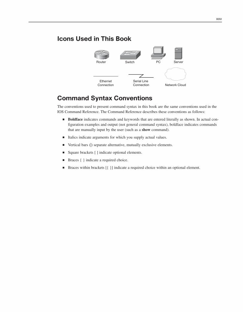
Icons Used in This Book
xxv
PC ServerRouter Switch
Network CloudEthernet
ConnectionSerial Line Connection
Command Syntax ConventionsThe conventions used to present command syntax in this book are the same conventions used in theIOS Command Reference. The Command Reference describes these conventions as follows:
■ Boldface indicates commands and keywords that are entered literally as shown. In actual con-figuration examples and output (not general command syntax), boldface indicates commandsthat are manually input by the user (such as a show command).
■ Italics indicate arguments for which you supply actual values.
■ Vertical bars (|) separate alternative, mutually exclusive elements.
■ Square brackets [ ] indicate optional elements.
■ Braces { } indicate a required choice.
■ Braces within brackets [{ }] indicate a required choice within an optional element.

IntroductionThe Cisco Networking Academy is a comprehensive e-learning program that provides students withInternet technology skills. A Networking Academy delivers web-based content, online assessment,student performance tracking, and hands-on labs to prepare students for industry-standard certifica-tions. The CCNA curriculum includes four courses oriented around the topics of the Cisco CertifiedNetwork Associate (CCNA) certification.
Routing Protocols and Concepts, CCNA Exploration Labs and Study Guide is a supplement to yourclassroom and laboratory experience with the Cisco Networking Academy. To be successful on theexam and achieve your CCNA certification, you should do everything in your power to arm yourselfwith a variety of tools and training materials to support your learning efforts. This Labs and StudyGuide is just such a collection of tools. Used to its fullest extent, it will help you gain the knowledgeas well as practice the skills associated with the content area of the CCNA Exploration RoutingProtocols and Concepts course. Specifically, this book will help you work on these main areas:
■ Basic Routing and Packet-Forwarding Concepts
■ Understanding and Configuring Static and Default Routes
■ Distance Vector Routing Protocol Concepts
■ RIPv1, RIPv2, and EIGRP Concepts and Configuration
■ IP Addressing with VLSM
■ Classful and Classless Routing
■ Link-State Routing Protocol Concepts
■ OSPF Concepts and Configuration
■ Troubleshooting Routing Issues
Labs and Study Guides similar to this one are also available for the other three courses: NetworkFundamentals, CCNA Exploration Labs and Study Guide; LAN Switching and Wireless, CCNAExploration Labs and Study Guide; and Accessing the WAN, CCNA Exploration Labs and StudyGuide.
A Word About Packet TracerPacket Tracer is a self-paced, visual, interactive teaching and learning tool developed by Cisco. Labactivities are an important part of networking education. However, lab equipment can be a scarceresource. Packet Tracer provides a visual simulation of equipment and network processes to offset thechallenge of limited equipment. Students can spend as much time as they like completing standard labexercises through Packet Tracer, and have the option to work from home. Although Packet Tracer isnot a substitute for real equipment, it allows students to practice using a command-line interface. This“e-doing” capability is a fundamental component of learning how to configure routers and switchesfrom the command line.
Packet Tracer v4.x is available only to Cisco Networking Academies through the AcademyConnection website.
xxvi Routing Protocols and Concepts, CCNA Exploration Labs and Study Guide
Goals and MethodsThe most important goal of this book is to help you pass the CCNA exam (640-802). Passing thisfoundation exam means that you not only have the required knowledge of the technologies covered bythe exam, but that you can also plan, design, implement, operate, and troubleshoot these technologies.In other words, these exams are rigorously application based. You can view the exam topics any timeat http://www.cisco.com/go/certifications. The topics are divided into eight categories:
■ Describe how a network works
■ Configure, verify, and troubleshoot a switch with VLANs and interswitch communications
■ Implement an IP addressing scheme and IP services to meet network requirements in a medium-size enterprise branch office network.
■ Configure, verify, and troubleshoot basic router operation and routing on Cisco devices
■ Explain and select the appropriate administrative tasks required for a WLAN
■ Identify security threats to a network and describe general methods to mitigate those threats
■ Implement, verify, and troubleshoot NAT and ACLs in a medium-size enterprise branch officenetwork
■ Implement and verify WAN links
The Routing Protocols and Concepts course focuses on the third and fourth bullets.
The Study Guide section offers exercises that help you learn the routing protocol concepts as well asthe configurations crucial to your success as a CCNA exam candidate. Each chapter is slightly differ-ent and includes some or all of the following types of exercises:
■ Vocabulary Matching and Completion
■ Skill-Building Activities and Scenarios
■ Configuration Scenarios
■ Concept Questions
■ Journal Entries
■ Internet Research
In the configuration chapters, you’ll find many Packet Tracer Activities that work with the CiscoPacket Tracer tool. Packet Tracer allows you to create networks, visualize how packets flow in the net-work, and use basic testing tools to determine whether the network would work. When you see thisicon, you can use Packet Tracer with the listed file to perform a task suggested in this book. The activ-ity files are available on this book’s CD-ROM; Packet Tracer software, however, is available throughthe Academy Connection website. Ask your instructor for access to Packet Tracer.
The Labs and Activities sections include a Command Reference table, all the online Curriculum Labs,and a Packet Tracer Skills Integration Challenge Activity. The Curriculum Labs are divided into threecategories:
■ Basic: The Basic Labs are procedural in nature and assume that you have no experience config-uring the technologies that are the topic of the lab.
■ Challenge: The Challenge Labs are implementation in nature and assume that you have a firmenough grasp on the technologies to “go it alone.” These labs often only give you a generalrequirement that you must implement fully without the details of each small step. In other
xxvii
Packet Tracer Activity

words, you must use the knowledge and skills you gained in the chapter text, activities, andBasic Lab to successfully complete the Challenge Labs. Avoid the temptation to work throughthe Challenge Lab by flipping back through the Basic Lab when you are not sure of a com-mand. Do not try to short-circuit your CCNA training. You need a deep understanding ofCCNA knowledge and skills to ultimately be successful on the CCNA exam.
■ Troubleshooting: The Troubleshooting Labs will ask you to fix a broken network. These labsinclude corrupted scripts you purposefully load onto the routers. Then you use troubleshootingtechniques to isolate problems and implement a solution. By the end of the lab, you shouldhave a functional network with full end-to-end connectivity.
Each of the hands-on labs include Packet Tracer Companion Activities, where you can use PacketTracer to complete a simulation of the lab.
Each chapter also includes a culminating activity called the Packet Tracer Skills IntegrationChallenge. These activities require you to pull together several skills learned from the chapter—as well as previous chapters and courses—to successfully complete one comprehensive exercise.
Audience for This BookThis book’s main audience is anyone taking the CCNA Exploration Routing Protocols and Conceptscourse of the Cisco Networking Academy curriculum. Many Academies use this textbook as arequired tool in the course, while other Academies recommend the Companion Guides as an addition-al source of study and practice materials.
The secondary audiences for this book include people taking CCNA-related classes from professionaltraining organizations. This book can also be used for college- and university-level networking cours-es, as well as for anyone wanting to gain a detailed understanding of routing.
How This Book Is OrganizedBecause the content of Routing Protocols and Concepts, CCNA Exploration Companion Guide andthe online curriculum is sequential, you should work through this Labs and Study Guide in order,beginning with Chapter 1.
The book covers the major topic headings in the same sequence as the online curriculum for theCCNA Exploration Routing Protocols and Concepts course. This book has 11 chapters, with the samenumbers and similar names as the online course chapters.
Each routing protocol chapter and the static routing chapter begin with a single topology that is usedthroughout the chapter. The single topology per chapter allows better continuity and easier under-standing of routing commands, operations, and outputs. However, the topology is different than theone used in the online curriculum and the Companion Guide. A different topology affords you theopportunity to practice your knowledge and skills without just simply recording the information youfind in the text.
■ Chapter 1, “Introduction to Routing and Packet Forwarding”: This chapter begins withseveral exercises devoted to reinforcing your understanding of the basic hardware and softwarecomponents of a router as well as testing your knowledge of basic routing and packet forward-ing. Then you will practice the basic addressing and configuration skills that are crucial to allfuture chapters. The Study Guide portion of the chapter ends with a review of routing principles
xxviii Routing Protocols and Concepts, CCNA Exploration Labs and Study Guide

as well as explains how a router determines the path and switches the packet. The Lab portionincludes two versions of the Basic Lab, a Challenge Lab, and the Packet Tracer SkillsIntegration Challenge Activity.
■ Chapter 2, “Static Routing”: The exercises in the first part of this chapter will help youunderstand basic router configuration and verification as well as the concept of directly con-nected networks. Then the exercises cover, in detail, static routes, summary routes, and defaultroutes. The Lab portion of the chapter includes a Basic Lab, a Challenge Lab, aTroubleshooting Lab, and a Packet Tracer Skills Integration Challenge Activity.
■ Chapter 3, “Introduction to Dynamic Routing Protocols”: The exercises in this chapterfocus on the concepts of dynamic routing, including basic concepts and advantages, classifica-tion, metrics, administrative distance, and routing table elements. The Lab section includes sixsubnetting scenarios to help you hone your IP addressing design skills. The Lab section alsoincludes a Packet Tracer Skills Integration Challenge Activity.
■ Chapter 4, “Distance Vector Routing Protocols”: This chapter’s exercises are devoted to theconcepts of distance vector routing protocols, including their characteristics, how they maintainthe routing table, and how they guard against routing loops. The Lab section includes a routingtable interpretation activity and a Packet Tracer Skills Integration Challenge Activity.
■ Chapter 5, “RIP Version 1”: Exercises in this chapter focus on RIPv1 concepts, basic configuration, verification, troubleshooting, automatic summarization, and RIP default routepropagation. The Lab portion of the chapter includes a Basic Lab, a Challenge Lab, aTroubleshooting Lab, and a Packet Tracer Skills Integration Challenge Activity.
■ Chapter 6, “VLSM and CIDR”: This chapter is a transition from classful routing to classlessrouting. Therefore, exercises focus on the concepts and skills necessary for implementingVLSM addressing schemes and CIDR. The Lab section includes three VLSM design scenariosand three route summarization scenarios. The Lab section also includes a Packet Tracer SkillsIntegration Challenge Activity.
■ Chapter 7, “RIPv2”: The exercises in this chapter cover the concepts and configurations ofthe classless version of RIPv2. First, you explore how RIPv2 addresses the limitations ofRIPv1. Then you configure, verify, and troubleshoot RIPv2. The Lab portion of the chapterincludes a Basic Lab, a Challenge Lab, a Troubleshooting Lab, and a Packet Tracer SkillsIntegration Challenge Activity.
■ Chapter 8, “The Routing Table: A Closer Look”: This chapter represents a pivotal point inyour studies of routing protocols and concepts as you delve into exercises that take you deepinto the structure of the routing table. Understanding exactly how the routing table is construct-ed and then used by the IOS provides a valuable tool in verifying and troubleshooting net-works. The Lab portion of the chapter includes two routing table labs and a Packet Tracer SkillsIntegration Challenge Activity.
■ Chapter 9, “EIGRP”: Exercises in this chapter focus on EIGRP concepts, basic configuration,verification, troubleshooting, metric calculation, and DUAL operation as well as some moreadvanced EIGRP configurations. The Lab portion of the chapter includes a Basic Lab, aChallenge Lab, a Troubleshooting Lab, and a Packet Tracer Skills Integration ChallengeActivity.
■ Chapter 10, “Link-State Routing Protocols”: The exercises in this chapter help you transi-tion from distance vector routing protocols to link-state routing protocols. There are no labs forthis chapter. However, there is a Packet Tracer Skills Integration Challenge Activity.
xxix

■ Chapter 11, “OSPF”: This chapter concludes your studies of routing protocols with exercisesfocusing on basic OSPF concepts and configurations, including the OSPF metric calculation,OSPF multiaccess networks, and some advanced OSPF configurations for single-area OSPFimplementations. The Lab portion of the chapter includes a Basic Lab, a Challenge Lab, aTroubleshooting Lab, and a Packet Tracer Skills Integration Challenge Activity.
About the CD-ROMThe CD-ROM included with this book has all the Packet Tracer Activity, Packet Tracer Companion,and Packet Tracer Challenge files that are referenced throughout the book as indicated by the PacketTracer Activity, Packet Tracer Companion, and Packet Tracer Challenge icons.
Updates to these files can be obtained from the website for this book, http://www.ciscopress.com/title/1587132044. The files will be updated to cover any subsequent releases of Packet Tracer.
About the Cisco Press Website for This BookCisco Press will provide updated content that can be accessed by registering your individual book atthe ciscopress.com website. Becoming a member and registering is free, and you then gain access toexclusive deals on other resources from Cisco Press.
To register this book, go to http://www.ciscopress.com/bookstore/register.asp and enter the book’sISBN, which is located on its back cover. You’ll then be prompted to log in or join ciscopress.com tocontinue registration.
After you register the book, a link to any additional content will be listed on your My RegisteredBooks page.
xxx Routing Protocols and Concepts, CCNA Exploration Labs and Study Guide
Packet Tracer Activity
Packet Tracer Challenge
Packet Tracer Companion
CHAPTER 1
Introduction to Routing and Packet Forwarding
The Study Guide portion of this chapter uses a combination of matching, fill-in-the-blank, multiple-choice, andopen-ended question exercises to test your knowledge and skills of basic router concepts and configuration. TheLab Exercises portion of this chapter includes all the online curriculum labs to ensure that you have masteredthe hands-on skills needed to understand basic IP addresing and router configuration.
As you work through this chapter, use Chapter 1 in Routing Protocols and Concepts, CCNA ExplorationCompanion Guide or use the corresponding Chapter 1 in the Exploration Routing Protocols and Conceptsonline curriculum for assistance.

Study Guide
Inside the RouterA router is a computer and has many of the common hardware components found on other types of computers. A routeralso includes an operating system. The exercises in this section will reinforce your understanding of the basic hardwareand software components of a router. You will also gain a better understanding of the routing and packet-forwardingprocess.
Vocabulary Exercise: MatchingMatch the definition on the left with a term on the right. This exercise is not necessarily a one-to-one matching. Somedefinitions might be used more than once, and some terms might have multiple definitions.
2 Routing Protocols and Concepts, CCNA Exploration Labs and Study Guide
Definitions
a. Because routers do not necessarily have the sameinformation in their routing tables, packets cantraverse the network in one direction, using onepath, and return through another path.
b. Routing protocols use __________ to evaluatewhat path will be the best for a packet to travel toa destination network.
c. Routing that depends on manually entered routesin the routing table.
d. A management port on the router.
e. A company that provides WAN technologies toconnect the customer’s local networks to theInternet and other remote networks.
f. Most common LAN technology.
g. Table of IP address–to–MAC address mappingsused by routers that have Ethernet interfaces.
h. The fastest route to a certain destination, which isbased on the routing protocol’s metric.
i. A data link layer technology often used for WANlinks.
j. A dynamic routing protocol used by routers todetermine the best path for IP packets.
k. Port on the router that can be attached to amodem for remote management access.
l. A series of questions prompting the user for basicconfiguration information because the router didnot locate a startup configuration file.
m. A form of permanent storage used by Ciscodevices to store the bootstrap instructions, basicdiagnostic software, and a scaled-down version ofIOS.
n. A router’s ability to use multiple paths to thesame destination because the paths have the samemetric value.
o. Identifies how many routers can be traversed bythe datagram before being dropped.
p. Stores the instructions and data needed to be exe-cuted by the CPU.
q. An end device or node on the network thatimplies a computer system.
r. This router mode allows the user to make configu-ration changes. The router prompt will changefrom a “>” to a “#.”
s. A router’s ability to send packets over multiplenetworks, even when the metric is not the same.
t. Common process that occurs on most every com-puter during bootup to test the router hardware.
u. Used by the Cisco IOS as permanent storage forthe startup configuration file.
v. Nonvolatile computer memory that is used as per-manent storage for the operating system, CiscoIOS.
w. Port used to initially configure a router.
x. Used by the router to determine the best path toforward the packet.
y. Used by routers to automatically learn aboutremote networks and build their routing tables.

Chapter 1: Introduction to Routing and Packet Fowarding 3
Terms
__g ARP cache
__a asymmetric routing
__i Asynchronous Transfer Mode
d, k auxiliary port
__h best path
__j BGP
d, w console port
__y dynamic routing protocols
__j EIGRP
__n equal-cost load balancing
__f Ethernet
__v flash
__i Frame Relay
__q hosts
__j IGRP
__e Internet service provider (ISP)
__j IS-IS
__b metric
__u NVRAM
__j OSPF
__t power-on self test (POST)
__i Point-to-Point Protocol (PPP)
__r privileged EXEC
__p RAM
__j RIP
__m ROM
__x routing table
__l setup mode
__c static routing
__o Time to Live (TTL)
__s unequal-cost load balancing

Vocabulary Exercise: CompletionComplete the paragraphs that follow by filling in the appropriate words and phrases.
Routers Are Computers
A router is a computer, just like any other computer including a PC. Routers have many of the samehardware and software components that are found in other computers including
■ CPU
■ RAM
■ ROM
■ Operating system
Each network that a router connects to typically requires a separate interface. These interfaces areused to connect a combination of both local-area networks (LAN) and wide-area networks (WAN).LANs are commonly Ethernet networks that contain devices such as PCs, printers, and servers. WANsare used to connect networks over a large geographical area and are commonly used to connect aLAN to the Internet service provider’s (ISP) network.
The router’s primary responsibility is to forward packets destined for local and remote networks by
■ Determining the best path to send packets
■ Forwarding packets toward their destination
The router uses its routing table to determine the best path to forward the packet. When a match isfound, the router encapsulates the IP packet into the data-link frame of the outgoing or exit interface,and the packet is then forwarded towards its destination.
It is likely that a router will receive a packet encapsulated in one type of data-link frame, such as anEthernet frame, and when forwarding the packet, encapsulate it in a different type of data-link frame.
Static routes and dynamic routing protocols are used by routers to learn about remote networks andbuild their routing tables.
Router CPU and Memory
Like a PC, the CPU in a router executes operating system instructions, such as system initialization,routing functions, and network interface control.
Similar to other computers, RAM stores the instructions and data needed to be executed by the CPU.It is volatile memory that loses its content when the router is powered down or restarted. For this reason,the router also contains permanent storage areas such as ROM, flash, and NVRAM.
ROM is a form of permanent storage. On Cisco devices, it stores
■ The bootstrap instructions
■ Basic diagnostic software
■ Scaled-down version of IOS
In most models of Cisco routers, the IOS is permanently stored in flash memory and copied intoRAM during the bootup process.
NVRAM is nonvolatile random-access memory that does not lose its information when power isturned off. NVRAM is used by the Cisco IOS as permanent storage for the startup configuration file.
4 Routing Protocols and Concepts, CCNA Exploration Labs and Study Guide

Internetwork Operating System (IOS)
Like any operating system on any other computer, Cisco IOS is responsible for managing the hard-ware and software resources of the router. Although the Cisco IOS might appear to be the same onmany routers, there are many different IOS images: a file that contains the entire IOS for that router.
Although some routers provide a GUI (graphical user interface), the CLI (command-line interface) isa much more common method of configuring Cisco routers.
Upon bootup, the startup-config file in NVRAM is copied into RAM and stored as the running-configfile. Any changes entered by the network administrator are stored in the running-config file and imme-diately implemented by the IOS.
Router Bootup Process
Like all computers, a router uses a systematic process to boot up. The four phases are
1. POST: Testing the router hardware
2. Loading the bootstrap program
3. Locating and loading the IOS
4. Locating and loading the startup configuration file or entering setup mode
Power-on self test (POST) is a common process that occurs on most every computer during bootup.The POST process is used to test the router hardware.
After the POST, the bootstrap program is copied from ROM into RAM. Its job is to locate the CiscoIOS and load it into RAM.
After the IOS is loaded, it searches for the startup-config file. If this file is located, it is copied intoRAM as the running-config file. The IOS executes the commands in the file one line at a time.
If the startup configuration file cannot be located, the router will prompt the user to enter setup mode,a series of questions prompting the user for basic configuration information. Setup mode will not beused in this course.
After the normal loading process is completed and the prompt is displayed, the router is now runningthe IOS with the current running configuration file. The network administrator can now begin usingIOS commands on this router.
The show version command can be used to help verify and troubleshoot some of the basic hardwareand software components of the router.
Router Ports and Interfaces
Routers have management ports, which are physical connectors used by the administrator to configurethe router and are not used for packet forwarding. The most common of the management ports is theconsole port. It must be used during initial configuration of the router. Another management port isthe auxiliary port, which can also be used to attach a modem.
The term interface on Cisco routers refers to a physical connector on the router whose main purposeis to receive and forward packets. Routers have multiple interfaces used to connect to multiple net-works.
Every interface on the router is a member, a host on a different IP network. A router’s Ethernet inter-face usually uses an RJ-45 jack that supports unshielded twisted-pair (UTP) cabling. When a router isconnected to a switch, a straight-through cable is used. When a PC’s network interface card (NIC) is
Chapter 1: Introduction to Routing and Packet Fowarding 5

connected directly to a router’s Ethernet interface, a crossover cable is used.
Similar to LAN interfaces, each WAN interface has its own IP address and subnet mask, making it amember of a specific network. Remember, MAC addresses are used only on Ethernet interfaces andare not on WAN interfaces.
Routers and the Network Layer
Key to understanding the role of a router in the network is to understand that a router is a Layer 3device responsible for forwarding packets. However, a router also operates at Layers 1 and 2.
The main purpose of a router is to connect multiple networks and forward packets destined for its ownnetworks or other networks. A router is considered a Layer 3 device because its primary forwardingdecision is based on the information in the Layer 3 IP packet, specifically the destination IP address.This is known as routing.
When a router receives a packet, it examines the destination IP address. If the packet does not belongto any of the router’s directly connected networks, the router must forward this packet to anotherrouter or drop the packet.
When forwarding a packet, the router will encapsulate the Layer 3 IP packet into the data portion of aLayer 2 data-link frame appropriate for the exit interface. The Layer 2 frame will then be encoded intothe Layer 1 physical signals used to represent these bits over the physical link.
Label the External Components of a Router ExerciseChoose the correct label description for each number shown in Figure 1-1.
6 Routing Protocols and Concepts, CCNA Exploration Labs and Study Guide
Figure 1-1 Rear View of an 1841 Cisco Router
Figure 1-1 Label Description:
7 Alternative management port that can support remote access through a modem
3 Single-slot USB port
1 4-port Cisco EtherSwitch 10BASE-T/100BASE-TX autosensing high-speed WAN interfacecard
6 FastEthernet port 0/0
8 High-speed WAN interface card with two serial interfaces
2 Compact flash module
5 Management port used for local access to the device; must be used for initial configuration
4 FastEthernet port 0/1

Label the Internal Components of a Router ExerciseChoose the correct label description for each number shown in Figure 1-2.
Figure 1-2 Logical Diagram of the Internal Components of an 1841 Cisco Router
Chapter 1: Introduction to Routing and Packet Fowarding 7
Aux Console
SystemBusCPU Bus
Slot0HWIC/WIC/VWIC
Slot1HWIC/WIC/VWIC
FastEthernet0/0
FastEthernet0/1
SystemControlASIC
SDRAMDIMMs128 MB
(Expandable to348 MB)
CPUM860
Processor
User InterfaceDual UART
Compact FlashMemory Card
Flash32, 64 or 128 MBdefault is 32 MB
Boot ROM
NVRAM
2 or 4 MBFlash Memory
1 2
3
4
5
6
8
7
9
10
Figure 1-2 Label Description:
3 Universal asynchronous receiver/transmitter, which controls the dual access through the con-sole and auxiliary ports
5 Holds the bootstrap program, ROM monitor, and possibly a scaled-down version of IOS soft-ware
10 Includes two modular slots and two built-in LAN interfaces
9 Holds running configuration, routing tables, and other data structures
6 Holds startup configuration
1 Management port used for remote configuration through a modem; not all routers have one ofthese
7 Loads instructions defined in Cisco IOS Software from the main processor memory and exe-cutes them
8 Controls the flow of data among memory, interfaces, and the CPU
2 Management port used for local configuration of the device
4 Stores the Cisco IOS Software image
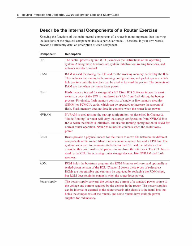
Describe the Internal Components of a Router ExerciseKnowing the functions of the main internal components of a router is more important than knowingthe locations of the physical components inside a particular model. Therefore, in your own words,provide a sufficiently detailed description of each component.
Component Description
CPU The central processing unit (CPU) executes the instructions of the operating system. Among these functions are system initialization, routing functions, and network interface control.
RAM RAM is used for storing the IOS and for the working memory needed by the IOS. This includes the routing table, running configurations, and packet queues, which hold packets until the interface can be used to forward the packet. The contents of RAM are lost when the router loses power.
Flash Flash memory is used for storage of a full Cisco IOS Software image. In most routers, a copy of the IOS is transferred to RAM from flash during the bootup process. Physically, flash memory consists of single in-line memory modules (SIMM) or PCMCIA cards, which can be upgraded to increase the amount of flash. Flash memory does not lose its contents when the router loses power.
NVRAM NVRAM is used to store the startup configuration. As described in Chapter 2,“Static Routing,” a router will copy the startup configuration from NVRAM into RAM when the router is initialized, and use the running configuration in RAM for normal router operation. NVRAM retains its contents when the router loses power.
Buses Buses provide a physical means for the router to move bits between the different components of the router. Most routers contain a system bus and a CPU bus. The system bus is used to communicate between the CPU and the interfaces. For example, this bus transfers the packets to and from the interfaces. The CPU bus is used by the CPU for accessing router storage devices, like NVRAM and flash memory.
ROM ROM holds the bootstrap program, the ROM Monitor software, and optionally a scaled-down version of the IOS. (Chapter 2 covers these types of software.) ROMs are not erasable and can only be upgraded by replacing the ROM chips,but ROM does retain its contents when the router loses power.
Power supply The power supply converts the voltage and current of a standard power source to the voltage and current required by the devices in the router. The power supplies can be internal or external to the router chassis (the chassis is the metal box that holds the components of the router), and some routers have multiple power supplies for redundancy.
8 Routing Protocols and Concepts, CCNA Exploration Labs and Study Guide

Another way to learn the internal components of a router is by listing the components’ functions. Foreach component from the following list, indicate in the table that follows which component performsthe listed function:
A. RAM
B. NVRAM
C. Flash
D. ROM
E. Interfaces
Answer Function
A Provides temporary memory for the configuration file of the router while the router is powered on
C Allows software to be updated without removing and replacing chips on the processor
A Stores routing tables
D Maintains instructions for power-on self test (POST) diagnostics
E Connects the router to the network for frame entry and exit
E Can be on the motherboard or on a separate module
C Is a type of electronically erasable programmable ROM (EEPROM)
B Retains content when router is powered down or restarted
D Stores bootstrap program and basic operating system software
A Holds ARP cache
A Loses content when router is powered down or restarted
B Retains content when router is powered down or restarted
C Holds the operating system image (IOS)
B Provides storage for the startup configuration file
C Can store multiple versions of IOS software
Chapter 1: Introduction to Routing and Packet Fowarding 9

Router Bootup Process ExerciseFigure 1-3 displays an incomplete diagram of the default boot sequence of a router. Provide detailwhere information is missing.
Figure 1-3 Diagram of the Router Boot Sequence
10 Routing Protocols and Concepts, CCNA Exploration Labs and Study Guide
CiscoInternetworking
Operating System
Locate and LoadConfiguration Fileor enter “setup”
mode
POSTROM
ROM
Flash
ROM
NVRAM
TFTP Server
Locate and Loadthe Operating
System
Configuration
Bootstrap Load Bootstrap
TFTP Server
Console
Tests Hardware
Interpreting the show version Command ExerciseFigure 1-4 displays the output from the show version command with parts of the output numbered.Choose the correct label description for each number shown in the figure.
Figure 1-4 show version Command
Router#show version
Cisco Internetwork Operating System Software
IOS (tm) C2600 Software (C2600-I-M), Version 12.2(28), RELEASE SOFTWARE (fc5)
Technical Support: http://www.cisco.com/techsupport
Copyright (c) 1986-2005 by cisco Systems, Inc.
Compiled Wed 27-Apr-04 19:01 by miwang
Image text-base: 0x8000808C, data-base: 0x80A1FECC
ROM: System Bootstrap, Version 12.1 (3r)T2, RELEASE SOFTWARE (fc1)
Copyright (c) 2000 by cisco Systems, Inc.
ROM: C2600 Software (C2600-I-M), Version 12.2(28), RELEASE SOFTWARE (fc5)
System returned to ROM by reload
System image file is “flash:c2600-i-mz.122-28.bin”
cisco 2621 (MPC860) processor (revision 0x200) with 60416K/5120K bytes of memory
.
Processor board ID JAD05190MTZ (4292891495)
M860 processor: part number 0, mask 49
Bridging software.
X.25 software, Version 3.0.0.
2 FastEthernet/IEEE 802.3 interface(s)
2 Low-speed serial(sync/async) network interface(s)
32K bytes of non-volatile configuration memory.
16384K bytes of processor board System flash (Read/Write)
Configuration register is 0x2102
Router#
1
2
34
567

Figure 1-4 Label Description:
2 Bootstrap version
5 Number and type of interfaces
7 Amount of flash
3 Model and CPU
4 Amount of RAM
6 Amount of NVRAM
1 IOS version
CLI Configuration and AddressingThe basic addressing and configuration of Cisco devices were covered in a previous course. However,we will spend some time reviewing these topics as well as prepare you for the hands-on lab experi-ence in this course.
Implementing Basic Addressing Schemes ExerciseWhen designing a new network or mapping an existing network, it is important to document the net-work. At a minimum, the documentation should include a topology map of the network and anaddressing table that lists the following information:
■ Device names
■ Interface
■ IP address and subnet mask
■ Default gateway address for end devices such as PCs
Refer to the topology shown in Figure 1-5 and Table 1-1 that follows it. Using the following guide-lines, fill in the addressing table with the correct information:
■ The routers use the first address in each network for the LANs.
■ R1 uses the first address and R2 uses the second address for the WAN.
■ The PCs use the tenth address.
Figure 1-5 Chapter 1 Study Guide Topology
Chapter 1: Introduction to Routing and Packet Fowarding 11
172.16.0.0/16
Fa0/0 Fa0/0
S0/0/0DCE
S0/0/0PC1 PC2Switch1 R1 R2
172.17.0.0/16 172.18.0.0/16

Table 1-1 Addressing Table for Chapter 1 Topology
Device Interface IP Address Subnet Mask Default Gateway
R1 Fa0/0 172.16.0.1 255.255.0.0 —
S0/0/0 172.17.0.1 255.255.0.0 —
R2 Fa0/0 172.18.0.1 255.255.0.0 —
S0/0/0 172.17.0.2 255.255.0.0 —
PC1 NIC 172.16.0.10 255.255.0.0 172.16.0.1
PC2 NIC 172.18.0.10 255.255.0.0 172.18.0.1
Basic Router Configuration ExerciseWhen configuring a router, there are certain basic tasks that are performed, including
■ Naming the router
■ Setting passwords
■ Configuring interfaces
■ Configuring a banner
■ Saving changes on a router
■ Verifying basic configuration and router operations
The first prompt is at user mode and will allow you to view the state of the router. What major limita-tion does this mode have?
User mode will not allow you to modify the router configuration.
What is the router prompt for this mode?
Router>
The enable command is used to enter the privileged mode. What is the major difference between thismode and the previous mode?
Privileged mode allows the user to make configuration changes on the router.
What is the router prompt for this mode?
Router#
Basic Configuration Tasks
Table 1-2 lists the basic router configuration tasks in the left column. Fill in the right column with thecorrect command syntax for each of the tasks.
12 Routing Protocols and Concepts, CCNA Exploration Labs and Study Guide
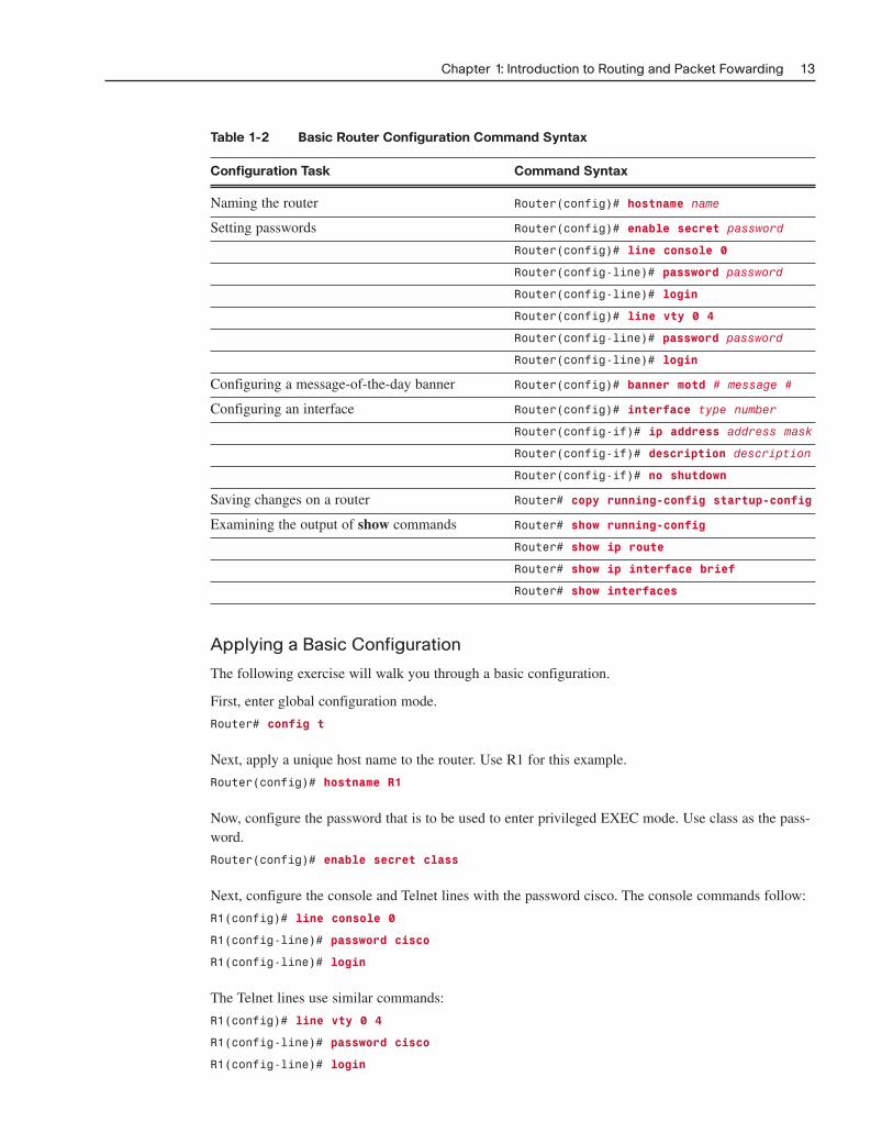
Table 1-2 Basic Router Configuration Command Syntax
Configuration Task Command Syntax
Naming the router Router(config)# hostname name
Setting passwords Router(config)# enable secret password
Router(config)# line console 0
Router(config-line)# password password
Router(config-line)# login
Router(config)# line vty 0 4
Router(config-line)# password password
Router(config-line)# login
Configuring a message-of-the-day banner Router(config)# banner motd # message #
Configuring an interface Router(config)# interface type number
Router(config-if)# ip address address mask
Router(config-if)# description description
Router(config-if)# no shutdown
Saving changes on a router Router# copy running-config startup-config
Examining the output of show commands Router# show running-config
Router# show ip route
Router# show ip interface brief
Router# show interfaces
Applying a Basic Configuration
The following exercise will walk you through a basic configuration.
First, enter global configuration mode.
Router# config t
Next, apply a unique host name to the router. Use R1 for this example.
Router(config)# hostname R1
Now, configure the password that is to be used to enter privileged EXEC mode. Use class as the pass-word.
Router(config)# enable secret class
Next, configure the console and Telnet lines with the password cisco. The console commands follow:
R1(config)# line console 0
R1(config-line)# password cisco
R1(config-line)# login
The Telnet lines use similar commands:
R1(config)# line vty 0 4
R1(config-line)# password cisco
R1(config-line)# login
Chapter 1: Introduction to Routing and Packet Fowarding 13

From global configuration mode, configure the message-of-the-day banner. Use the following text:Authorized Access Only. A delimiting character, such as a #, is used at the beginning and at the endof the message.
R1(config)# banner motd # Authorized Access Only #
What is the purpose of the message of the day?
At a minimum, a banner should warn against unauthorized access. Never configure a banner that“welcomes” an unauthorized user.
Refer to Figure 1-5 for the correct interface designations. What is the command to enter interface con-figuration mode for R1’s serial interface?
R1(config)# interface Serial0/0/0
Enter the command to configure the IP address using the address you specified in Table 1-1.
R1(config-if)# ip address 172.17.0.1 255.255.255.0
Describe the interface with the following text: Link to R2.
R1(config-if)# description Link to R2
Because R1 is on the data communications equipment (DCE) side, set the clocking signal to 64000.
R1(config-if)# clock rate 64000
Activate the interface.
Router(config-if)# no shutdown
Now enter the commands to configure and activate the Fast Ethernet interface on R1. Use the follow-ing description text: R1 LAN.
R1(config)# interface FastEthernet0/0
R1(config-if)# ip address 172.16.0.1 255.255.255.0
R1(config-if)# description R1 LAN
R1(config-if)# no shutdown
What command will save the current configuration?
Router# copy running-config startup-config
Verifying Basic Router Configuration
Basic configurations can be verified using four basic show commands. In Table 1-3, list the commandin the left column that fits the description in the right column.
Table 1-3 Basic Router Configuration Verification Commands
Command Description
show running-config Displays the current running configuration that is stored in RAM
show startup-config Displays the startup configuration file stored in NVRAM
show ip route Displays the routing table that the IOS is currently using to choose the best path to its destination networks
14 Routing Protocols and Concepts, CCNA Exploration Labs and Study Guide

Command Description
show interfaces Displays all the interface configuration parameters and statistics
show ip interface brief Displays abbreviated interface configuration information, including IP address and interface status
Packet Tracer Exercise 1-1: Basic RouterConfigurationNow you are ready to use Packet Tracer to apply your documented addressing scheme. Open fileLSG02-0101.pka on the CD-ROM that accompanies this book to perform this exercise using PacketTracer.
Note: The following instructions are also contained within the Packet Tracer Exercise.
Learning Objectives
■ Add Devices and Connect Cables
■ Configure PCs
■ Configure R1
■ Configure R2
■ Save the Packet Tracer file
Scenario
In this exercise, you will practice configuring the Chapter 1 Study Guide Topology (Figure 1-1). Usethe Addressing Table (Table 1-1) you completed in the section “Implementing Basic AddressingSchemes Exercise.”
Task 1: Add Devices and Connect CablesStep 1. Add two PCs: PC1 and PC2. Make sure that you name both PCs. Attach PC1 to S1 and
PC2 to R2.
Step 2. Connect the devices. Attach R1 to S1. Attach R1 to R2. Make sure that R1 is the DCE sideof the connection.
Step 3. Your completion percentage should be 11%. If not, click Check Results to see whichrequired components are not yet completed.
Task 2: Configure PCsStep 1. Configure PC1 and PC2 according to the addressing table you filled out in the section
“Implementing Basic Addressing Schemes Exercise.” If you have not completed that exer-cise, do so now.
Step 2. Check results. Both PCs should now be configured. Your completion percentage should be21%. If not, click Check Results to see which required components are not yet completed.
Chapter 1: Introduction to Routing and Packet Fowarding 15
Packet Tracer Activity

Task 3: Configure R1Step 1. Configure the host name, banner, enable secret password, console and Telnet lines accord-
ing to the following guidelines:
■ To avoid incorrect grading, make sure that all names and text strings are case sensitive,with no spacing before or after the name or text string.
■ Use the host name R1.
■ Use the following text for the banner: Authorized Access Only.
■ For the secret password, use class. (Note: The activity does not grade this configura-tion.)
■ For the console and Telnet lines, configure login access with the password cisco.
■ Your completion percentage should be 46%. If not, click Check Results to see whichrequired components are not yet completed.
Step 2. Configure the Fast Ethernet interface.
■ Use the IP address and subnet mask according to the addressing table in the section“Implementing Basic Addressing Schemes Exercise.”
■ Describe the link as R1 LAN.
■ Activate the interface.
■ Your completion percentage should be 53%. If not, click Check Results to see whichrequired components are not yet completed.
Step 3. Configure the serial interface.
■ Use the IP address and subnet mask according to the addressing table in the section“Implementing Basic Addressing Schemes Exercise.”
■ Describe the link as Link to R2.
■ R1 provides clocking at 64,000 bps.
■ Activate the interface.
■ R1 is now configured. Your completion percentage should be 61%. If not, click CheckResults to see which required components are not yet completed.
Step 4. Save the configuration to R1.
Task 4: Configure R2Step 1. Configure the host name, banner, enable secret password, and console and Telnet lines
according to the following guidelines:
■ To avoid incorrect grading, make sure that all names and text strings are case sensitive,with no spacing before or after the name or text string.
■ Use the host name R2.
■ Use the following text for the banner: Authorized Access Only.
■ For the secret password, use class. (Note: The activity does not grade this configuration.)
16 Routing Protocols and Concepts, CCNA Exploration Labs and Study Guide
■ For the console and Telnet lines, configure login access with the password cisco.
■ Your completion percentage should be 86%. If not, click Check Results to see whichrequired components are not yet completed.
Step 2. Configure the Fast Ethernet interface.
■ Use the IP address and subnet mask according to the addressing table in the section“Implementing Basic Addressing Schemes Exercise.”
■ Describe the link as R2 LAN.
■ Activate the interface.
■ Your completion percentage should be 93%. If not, click Check Results to see whichrequired components are not yet completed.
Step 3. Configure the serial interface.
■ Use the IP address and subnet mask according to the addressing table in the section“Implementing Basic Addressing Schemes Exercise.”
■ Describe the link as Link to R1.
■ Activate the interface.
■ R1 is now configured. Your completion percentage should be 100%. All the connectiv-ity tests should show a status of “successful.” If not, click Check Results to see whichrequired components are not yet completed.
Step 4. Save the configuration to R2.
Task 5: Save the Packet Tracer FileSave your Packet Tracer file as LSG02-0101-end.pka. You will use this file to complete some of theremaining exercises in this chapter.
Building the Routing TableThe primary function of a router is to forward packets toward the destination network, the destinationIP address of the packet. To do this, a router needs to search the routing information stored in its rout-ing table. In this section, you will learn how a router builds the routing table. Then, you will learn thethree basic routing principles.
Vocabulary Exercise: CompletionComplete the paragraphs that follow by filling in appropriate words and phrases.
Introducing the Routing Table
A routing table is a data file stored in RAM that is used to store route information about directly con-nected and remote networks.
There are two major types of routes in the routing table:
■ A directly connected network: When a router’s interface is configured with an IP address andsubnet mask, the interface becomes a host on that attached network.
Chapter 1: Introduction to Routing and Packet Fowarding 17

■ A remote network: This is a network that can only be reached by sending the packet to anotherrouter. These networks are added to the routing table by using a dynamic routing protocol or byconfiguring static routes. Dynamic routes are routes to remote networks that were learned auto-matically by the router. Static routes are routes to networks that a network administrator manu-ally configured.
show ip route Command
Describe the meaning of each part of the following route entry:
C 172.16.0.0/16 is directly connected, FastEthernet0/0
■ C: The information in this column denotes the source of the route information, directly con-nected network, static route, or a dynamic routing protocol. The C represents a directly con-nected route.
■ 172.16.0.0/24: This is the network address and subnet mask of the directly connected or remotenetwork.
■ FastEthernet 0/0: The information at the end of the route entry represents the exit interfaceand/or the IP address of the next-hop router. In this example, both FastEthernet 0/0 and Serial0/0/0 are the exit interfaces used to reach these networks.
Static Routing
When the IOS learns about a remote network and the interface it will use to reach that network, itadds that route to the routing table, as long as the exit interface is enabled.
Static routes are denoted with the code S in the routing table.
List and describe three situations in which static routes should be used.
■ A network consists of only a few routers. Using a dynamic routing protocol in such a casedoes not present any substantial benefit. On the contrary, dynamic routing can add more admin-istrative overhead.
■ A network is connected to the Internet only through a single ISP. There is no need to use adynamic routing protocol across this link because the ISP represents the only exit point to theInternet.
■ A large network is configured in a hub-and-spoke topology. A hub-and-spoke topology con-sists of a central location (the hub) and multiple branch locations (spokes), with each spokehaving only one connection to the hub. Using a dynamic routing protocol would be unnecessarybecause each branch only has one path to a given destination—through the central location.
Dynamic Routing
Dynamic routing protocols are used by routers to share information about the reachability and statusof remote networks. Dynamic routing protocols perform several activities, including
■ Network discovery, which is a routing protocol’s ability to share information about the net-works it knows about with other routers that are also using the same routing protocol
■ Maintain routing tables, which is a routing protocol’s ability to compensate for any topologychanges without involving the network administrator
18 Routing Protocols and Concepts, CCNA Exploration Labs and Study Guide
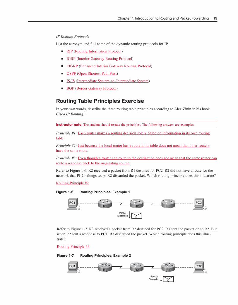
IP Routing Protocols
List the acronym and full name of the dynamic routing protocols for IP.
■ RIP (Routing Information Protocol)
■ IGRP (Interior Gateway Routing Protocol)
■ EIGRP (Enhanced Interior Gateway Routing Protocol)
■ OSPF (Open Shortest Path First)
■ IS-IS (Intermediate System–to–Intermediate System)
■ BGP (Border Gateway Protocol)
Routing Table Principles ExerciseIn your own words, describe the three routing table principles according to Alex Zinin in his bookCisco IP Routing.1
Instructor note: The student should restate the principles. The following answers are examples.
Principle #1: Each router makes a routing decision solely based on information in its own routingtable.
Principle #2: Just because the local router has a route in its table does not mean that other routershave the same route.
Principle #3: Even though a router can route to the destination does not mean that the same router canroute a response back to the originating source.
Refer to Figure 1-6. R2 received a packet from R1 destined for PC2. R2 did not have a route for thenetwork that PC2 belongs to, so R2 discarded the packet. Which routing principle does this illustrate?
Routing Principle #2
Figure 1-6 Routing Principles: Example 1
Chapter 1: Introduction to Routing and Packet Fowarding 19
PacketDiscarded
PC1 PC2R2R1 R3
PacketDiscarded
PC1 PC2R2R1 R3
Refer to Figure 1-7. R3 received a packet from R2 destined for PC2. R3 sent the packet on to R2. Butwhen R2 sent a response to PC1, R3 discarded the packet. Which routing principle does this illus-trate?
Routing Principle #3
Figure 1-7 Routing Principles: Example 2

Refer to Figure 1-8. R1 received a packet from PC1 destined for PC2. R1 forwarded the packet to R2.Which routing principle does this illustrate?
Routing Principle #1
Figure 1-8 Routing Principles: Example 3
20 Routing Protocols and Concepts, CCNA Exploration Labs and Study Guide
PacketForwarded
PC1 PC2R2R1 R3
Type of Service Packet LengthVersion IHL
Identification Flags Fragment Offset
ProtocolTime to Live
Source IP Address
Destination IP Address
Options Padding
Header Checksum
Byte 2Byte 1 Byte 3 Byte 4
Preamble
7
DestinationAddress
61
SOF
SourceAddress
6
Length
2
802.2 Headerand Data
46-1500
FCS
4
Preamble
8
DestinationAddress
6
SourceAddress
6
Type
2
Data
46-1500
FCS
4
Field Length in Bytes
Field Length in Bytes
Ethernet
IEEE 802.3
Path Determination and Switching FunctionsThe following sections use exercises to focus your attention on exactly what happens to data as itmoves from source to destination. First, we review the packet and frame field specifications. Then, wediscuss in detail how the frame fields change from hop to hop, whereas the packet fields remainunchanged.
Internet Protocol (IP) Packet Format ExerciseFigure 1-9 shows the structure of fields for the packet header. Fill in the missing field names.
Figure 1-9 Field Specification for the IP Header
MAC Layer Frame Format ExerciseFigure 1-10 shows the two compatible version of Ethernet. Fill in the missing field names.
Figure 1-10 Field Specification for Ethernet Frames