routing static dynamics rip ospf igrp...
TRANSCRIPT

ROUTING STATIC DYNAMICS RIP OSPF IGRP EIGRPRouting is the process of determining where to send data packets that are destined for addresses outside the local network. Routers gather and maintain routing information to enable the transmission and receipt of these data packets.Routing information takes the form of entries in a routing table, with one entry for each identified route. The router can use a routing protocol to create and maintain the routing table dynamically so that network changes can be accommodated whenever they occur.It is important to understand dynamic routing and how the various types of routing protocols, such as distance vector and link-state, determine IP routes. It is equally important to understand scalability and convergence constraints with routing protocols.In this section we would cover following CCNA objectives Describe the purpose and types of dynamic routing protocols Describe the operation and implementation of distance vector routing protocols Describe the operation and implementation of link-state routing protocols
Basic of routing distance vector protocol problems solutionsRouting is the process by which a packet gets from one location to another. To route a packet, a router needs to know the destination address and on what interface to send the traffic out .When a packet comes into an interface (in interface) on a router, it looks up the destination IP address in the packet header and compares it with its routing table. The routing table, which is stored in RAM, tells the router which outgoing interface the packet should go out to reach the destination network. There are three ways to control routing decisions on your router:
Static routes
Default routes
Dynamic routes
Static RoutesUse a static route when you want to manually define the path that the packet will take through your network. Static routes are useful in small networks with rarely changing routes, when you have little bandwidth and do not want the overhead of a dynamic routing protocol, or when you want to manually define all of your routes for security reasons. Static routes are created in global configuration mode. The syntax for the static route is as follows: ip route destination network address [subnet mask] {next-hop-address | interface] [distance]
Defaults routersThis is the special type of static route, commonly called the gateway of last resort. If the specified destination is not listed in the routing table, the default route can be used to route the packet. A default route has an IP address of 0.0.0.0 and a subnet mask of 0.0.0.0, often represented as 0.0.0.0/0. Default routes are commonly used in small networks on a perimeter router pointing to the directly connected ISP router.
Dynamic RoutesA router learns dynamic routes by running a routing protocol. Routing protocols will learn about routes from other neighboring routers running the same routing protocol. Through this sharing process, a router will eventually learn about all of the reachable network and subnet numbers in the network.Now be familiar with the terms routing protocol and routed protocol that have two different meanings. A routing protocol learns about routes for a routed protocol.

Routed protocol:Any network protocol that provides enough information in its network layer address to enable a packet to be forwarded from one host to another host based on the addressing scheme, without knowing the entire path from source to destination. Packets generally are conveyed from end system to end system. IP is an example of a routed protocol.
Routing protocol:Facilitates the exchange of routing information between networks, enabling routers to build routing tables dynamically. Traditional IP routing stays simple because it uses next-hop (next-router) routing, in which the router needs to consider only where it sends the packet and does not need to consider the subsequent path of the packet on the remaining hops (routers). Routing Information Protocol (RIP) is an example of a routing protocol.There are two types of routing protocols: Interior Gateway Protocols (IGP): These routing protocols exchange routing information within an autonomous
system. Routing Information Protocol version 2 (RIPv2), Enhanced Interior Gateway Routing (EIGRP), and Open Shortest Path First (OSPF) are examples of IGPs.
Exterior Gateway Protocols (EGP): These routing protocols are used to route between autonomous systems. Border Gateway Protocol (BGP) is the EGP of choice in networks today.
MetricsMetrics can be calculated based on a single characteristic of a path. More complex metrics can be calculated by combining several path characteristics. The metrics that routing protocols most commonly use are as follows: Hop count:
The number of times that a packet passes through the output port of one router Bandwidth:
The data capacity of a link; for instance, normally, a 10-Mbps Ethernet link is preferable to a 64-kbps leased line Delay:
The length of time that is required to move a packet from source to destination Load:
The amount of activity on a network resource, such as a router or link Reliability:
Usually refers to the bit error rate of each network link Cost:
A configurable value that on Cisco routers is based by default on the bandwidth of the Interface
Routing Protocols Metric Description
RIP Hop count How many layer 3 hops away from the destination
OSPF Cost Measurement in the inverse of the bandwidth of the links
EIGRP Bandwidth The capacity of the links in Kbps (T1 = 1554)
EIGRP Delay Time it takes to reach the destination
EIGRP Load The path with the least utilization
EIGRP MTU The path that supports the largest frame sizes
EIGRP Reliability The path with the least amount of errors or down time
Autonomous Systems

An autonomous system (AS) is a group of networks under a single administrative control, which could be your company, a division within your company, or a group of companies.Not every routing protocol understands the concept of an AS. Routing protocols that understand the concept of an AS are EIGRP, OSPF, IS-IS, and BGP. RIP doesn’t understand autonomous systems, while OSPF does; but OSPF doesn’t require you to configure the AS number, whereas other protocols, such as EIGRP, do.
Administrative DistanceAdministrative distance is the measure of trustworthiness that a router assigns to how a route to a network was learned. An administrative distance is an integer from 0 to 255. A routing protocol with a lower administrative distance is more trustworthy than one with a higher administrative distance.Administrative Distance Route Type
0 Connected interface route
1 Static route
90 Internal EIGRP route (within the same AS)
110 OSPF route
120 RIPv1 and v2 route
170 External EIGRP (from another AS)
255 Unknown route (is considered an invalid route and will not be used)
Routing protocols can be further classified into two categories:
Distance vector routing protocols
Link state routing protocols
Distance Vector Routing ProtocolsDistance vector–based routing algorithms (also known as Bellman-Ford-Moore algorithms) pass periodic copies of a routing table from router to router and accumulate distance vectors. (Distance means how far, and vector means in which direction.) Regular updates between routers communicate topology changes.Sometimes these protocols are referred to as routing by rumor, since the routers learn routing information from directly connected neighbors, and these neighbors might have learned these networks from other neighboring routers. RIP is an example of a routing protocol that is a distance vector.
Advertising UpdatesRouters running distance vector protocols learn who their neighbors are by listening for routing broadcasts on their interfaces. No formal handshaking process or hello process occurs to discover who are the neighboring routers. Distance vector protocols assume that through the broadcast process, neighbors will be learned, and if a neighbor fails, the missed broadcasts from these neighbors will eventually be detectedDistance vector algorithms call for each router to send its entire routing table to each of its adjacent or directly connected neighbors. Distance vector routing tables include information about the total path cost (defined by its metric) and the logical address of the first router on the path to each network it knows about.

When a router receives an update from a neighboring router, it compares the update to its own routing table. The router adds the cost of reaching the neighboring router to the path cost reported by the neighbor to establish the new metric. If the router learns about a better route (smaller total metric) to a network from its neighbor, the router updates its own routing table.
Distance Vector Protocol Problems and SolutionsProblem: ConvergenceThe term convergence refers to the time it takes for all of the routers to understand the current topology of the network. When a router receives an update from a neighboring router, it compares the update to its own routing table. The router adds the cost of reaching the neighboring router to the path cost reported by the neighbor to establish the new metric. If the router learns about a better route (smaller total metric) to a network from its neighbor, the router updates its own routing table. It’s too time consuming process. Because in a 10 router topology last router will know about the network of first router only while all middle router will complete their periodic update. For example if interval timer is set to 60 second then last router will know about first network in 60*8 480 second or 8 minute.
Solution: Change the periodic timer intervalOne solution is to change the periodic timer interval. For instance, in an example the timer was set to 60 seconds. To speed up convergence, you might want to set the interval to 10 seconds. Also, by setting the timer to 10 seconds, you are creating six times the amount of routing broadcast traffic, which is not very efficient
A second solution is to implement triggered updatesThe distance vector routing protocol would still generate periodic updates; however, whenever a change takes place, the router will immediately generate an update without waiting for the periodic timer to expire. This can decrease convergence times, but it also creates a problem. If you have a flapping route, then an update will be triggered each time the route changes state, which creates a lot of unnecessary broadcast traffic in your network and could cause a broadcast storm.
Problem: Routing LoopsA routing loop is a layer-3 loop in the network. Basically, it is a disagreement about how to reach a destination network. Because distance vector routing protocols trust the next router without compiling a topology map of all networks and routers, distance vector protocols run the risk of creating loops in a network. This is analogous of driving to a location without a map. Instead, you trust what each sign tells you. Trusting the street signs might get you where you want to go, but I've been in some cities where trusting what the signs say will lead you in loops. The same is true with distance vector routing protocols. Simply trusting what the next router tells it can potentially lead the packets to loop endlessly. These loops could saturate a network and cause systems to crash. This, in turn, makes managers very upset and means that you have to work late into the evening to fix it.
Solution: Counting to Infinity Solution: Maximum Hop CountIP packets have inherent limits via the Time-To-Live (TTL) value in the IP header. In other words, a router must reduce the TTL field by at least 1 each time it gets the packet. If the TTL value becomes 0, the router discards that packet. However, this does not stop the router from continuing to attempt to send the packet to a network that is down. To avoid this prolonged problem, distance vector protocols define infinity as some maximum number. This number refers to a routing metric, such as a hop count.
Solution: Split HorizonSplit horizon states that if a neighboring router sends a route to a router, the receiving router will not propagate this route back to the advertising router on the same interface. Split horizon prevents a router from advertising a route back out the same interface where the router originally learned the route. One way to eliminate routing loops and speed up

convergence is through the technique called split horizon. The split horizon rule is that sending information about a route back in the direction from which the original update came is never useful.
Solution: Route PoisoningAnother operation complementary to split horizon is a technique called route poisoning. Route poisoning attempts to improve convergence time and eliminate routing loops caused by inconsistent updates. With this technique, when a router loses a link, the router advertises the loss of a route to its neighbor device. Route poisoning enables the receiving router to advertise a route back toward the source with a metric higher than the maximum. The advertisement back seems to violate split horizon, but it lets the router know that the update about the down network was received. The router that received the update also sets a table entry that keeps the network state consistent while other routers gradually converge correctly on the topology change. This mechanism allows the router to learn quickly of the down route and to ignore other updates that might be wrong for the hold-down period. This prevents routing loops.A poisoned route has an infinite metric assigned to it. A poison reverse causes the router to break split horizon rule and advertise the poisoned route out all interfaces. When a router detects that one of its connected routes has failed, the router will poison the route by assigning an infinite metric to it. In IP RIP, the route is assigned a hop count of 16 (15 is the maximum), thus making it an unreachable network. When a router advertises a poised route to its neighbors, its neighbors break the rule of split horizon and send back to the originator the same poisoned route, called a poison reverse. This ensures that everyone received the original update of the poisoned route.
Solution:Hold-Down TimersIn order to give the routers enough time to propagate the poisoned route and to ensure that no routing loops occur while propagation is occurring; the routers implement a hold-down mechanism. During this period, the routers will freeze the poisoned route in their routing tables for the period of the hold-down timer, which is typically three times the interval of the routing broadcast update. When hold-down timers are used, a poisoned route will remain in the routing table until the timer expires. However, if a router with a poisoned route receives a routing update from a neighboring router with a metric that is the same or better than the original route, the router will abort the hold-down period, remove the poisoned route, and put the new route in its table. However, if a router receives a worse route from a neighboring router, the router treats this as a suspect route and assumes that this route is probably part of a routing loop, ignoring the update. One of the problems of using hold-down timers is that they cause the distance vector routing protocol to converge slowly—if the hold-down period is 180 seconds, you can’t use a valid alternative path with a worse metric until the hold-down period expires. Therefore, your users will lose their connections to this network for at least three minutes.Hold-down timers perform route maintenance as follows:
When a router receives an update from a neighbor indicating that a previously accessible network is now inaccessible, the router marks the route as inaccessible and starts a hold-down timer.
If an update arrives from a neighboring router with a better metric than originally recorded for the network, the router marks the network as accessible and removes the hold-down timer.
If at any time before the hold-down timer expires, an update is received from a different neighboring router with a poorer metric, the update is ignored. Ignoring an update with a higher metric when a holddown is in effect enables more time for the knowledge of the change to propagate through the entire network.
During the hold-down period, routes appear in the routing table as “possibly down.”
How to configure router step by step guide

In this article I would show basic router configuration commands. These commands are the essential part of router configuration. For demonstration purpose I used packet tracer software. If you haven’t install packet tracer read our previous article to download and install packet tracer. Create a topology as given in following imageor you can download this created topology and load in packet tracer
Basic Show CommandsRouter#show running-configBuilding configuration...
Current configuration : 419 bytes!version 12.4no service password-encryption!hostname Router!ip ssh version 1!interface FastEthernet0/0[output is Omitted]Active configuration is known as running-configuration. You can view it from router command line interface. showrunning-config command will display active configuration from memory. You can run this command from privileged mode. On a Cisco router active configuration is not saved automatically. So it would lost automatically in the event of power failure. To avoid it you need to save it manually with copy command.Router#show flashSystem flash directory:File Length Name/status 1 33591768 c1841-advipservicesk9-mz.124-15.T1.bin[33591768 bytes used, 30424616 available, 64016384 total]63488K bytes of processor board System flash (Read/Write)Flash memory is a special kind of memory on the router that contains the operating system image file(s). Unlike regular router memory, Flash memory continues to maintain the file image even after power is lost.Router#show historyThe routers Command Line Interface (CLI) maintains by default the last 10 commands you have entered in memory .You can retrieve previous commands by pressing UP Arrow KeyYou can retrieve next commands by pressing Down Arrow KeyRouter#show protocolsUse this command to view the status of the current layer 3 routed protocols running on your routerRouter#show versionCisco IOS Software, 1841 Software (C1841-ADVIPSERVICESK9-M), Version 12.4(15)T1,RELEASE SOFTWARE (fc2)Technical Support: http://www.cisco.com/techsupportCopyright (c) 1986-2007 by Cisco Systems, Inc.Compiled Wed 18-Jul-07 04:52 by pt_team
ROM: System Bootstrap, Version 12.3(8r)T8, RELEASE SOFTWARE (fc1)

System returned to ROM by power-onSystem image file is "flash:c1841-advipservicesk9-mz.124-15.T1.bin"[output is Omitted]Cisco 1841 (revision 5.0) with 114688K/16384K bytes of memory.Processor board ID FTX0947Z18EM860 processor: part number 0, mask 492 FastEthernet/IEEE 802.3 interface(s)1 Low-speed serial(sync/async) network interface(s)191K bytes of NVRAM.31360K bytes of ATA CompactFlash (Read/Write)
Configuration register is 0x2102This command will give you critical information, such as: router platform type, operating system revision, operating system last boot time and file location, amount of memory, number of interfaces, and configuration registerRouter#show clock*1:46:13.169 UTC Mon Nov 1 2009Will show you Router clockRouter#show hostswill display a cached list of hosts and all of their interfaces IP addressesRouter#show usersWill show a list of all users who are connected to the routerRouter#show interfaceswill give you detailed information about each interfaceRouter#show protocolswill show the global and interface-specific status of any layer 3 protocolsRouter#show ip interface briefInterface IP-Address OK? Method Status Protocol
FastEthernet0/0 10.0.0.1 YES manual up up
FastEthernet0/1 unassigned YES manual administratively down down
Serial0/0/0 20.0.0.1 YES manual up up
Vlan1 unassigned YES manual administratively down downRouter#This command will show brief descriptions about interface. This command mostly used in troubleshooting. There may be three possible conditions of status. UP :- interface is up and operational DOWN :- physical link is detected but there are some problem in configurations. Administratively down :- port is disable by shutdown command ( Default mode of any port on router.)R1#show ip routeCodes: C - connected, S - static, I - IGRP, R - RIP, M - mobile, B - BGP D - EIGRP, EX - EIGRP external, O - OSPF, IA - OSPF inter area N1 - OSPF NSSA external type 1, N2 - OSPF NSSA external type 2 E1 - OSPF external type 1, E2 - OSPF external type 2, E - EGP i - IS-IS, L1 - IS-IS level-1, L2 - IS-IS level-2, ia - IS-IS inter area * - candidate default, U - per-user static route, o - ODR P - periodic downloaded static route
Gateway of last resort is not set

C 10.0.0.0/8 is directly connected, FastEthernet0/0C 20.0.0.0/8 is directly connected, Serial0/0/0D 30.0.0.0/8 [90/40514560] via 20.0.0.2, 00:02:55, Serial0/0/0D 40.0.0.0/8 [90/41026560] via 20.0.0.2, 00:02:54, Serial0/0/0D 50.0.0.0/8 [90/41029120] via 20.0.0.2, 00:02:50, Serial0/0/0R1#This command will give a detail about known route. Router will not forward packet if route is not shown here for that packet. Router’s routing decision is made by this routing table. R1#show controllers serial 0/0/0Interface Serial0/0/0Hardware is PowerQUICC MPC860DCE V.35, clock rate 64000idb at 0x81081AC4, driver data structure at 0x81084AC0Most common use of this command is to find out whether the port is DCE end or DTE. If the port is DCE end then clock rate and bandwidth command will require. As you can see in output that port is DCE. R1#show ip protocols
Routing Protocol is "eigrp 1 " Outgoing update filter list for all interfaces is not set Incoming update filter list for all interfaces is not set Default networks flagged in outgoing updates Default networks accepted from incoming updates EIGRP metric weight K1=1, K2=0, K3=1, K4=0, K5=0 EIGRP maximum hopcount 100 EIGRP maximum metric variance 1Redistributing: eigrp 1 Automatic network summarization is in effect Automatic address summarization: Maximum path: 4 Routing for Networks: 10.0.0.0 20.0.0.0 Routing Information Sources: Gateway Distance Last Update 20.0.0.2 90 16 Distance: internal 90 external 170 Use this command to know about running routing protocols. This will give the complete status about routing protocols likes on which interface its receiving updates and on which interface its broadcasting update what is time intervalspress enter to get back router promptRouter>You are now in User mode. Type ? to view all the available commands at this prompt.Router>?From privilege mode you can enter in configuration mode by typing configure terminal you can exit configuration mode type exit or <CTL>+zRouter>enableRouter#config terminalRouter(config)#exitRouter#To view all commands available from this mode type: ? and press: enter This will give you the list of all available commands for the router in your current mode. You can also use the question mark after you have started typing a command. For example if you want to use a show command but you do not remember which one it uses 'show ?' will output all commands that you can use with the show command. Router#show ?

access-expression List access expressionaccess-lists List access listsbackup Backup statuscdp CDP informationclock Display the system clockcls DLC user informationcompress Show compression statisticsconfiguration Contents of Non-Volatile memory--More--I have uploaded a configured and tested topology in case you are unable to locate the problem spot then download this configuration file. And try to find out where have you committed mistakeBasic router configuration
How to configure Cisco router in CCNA step by step guideIn this article we would extend what you have learnt from previous article. In previous article you have learnt How to check running configuration in Cisco router How to check history How to check Router version How to check Router hardware platform How to know DCE or DTE portWe would use same topology which we have created in our previous article. Either create a topology as given in following imageor you can download this created topology and load in packet tracer
Click inside the Router and select CLI and press Enter to get started. Setup mode start automatically if there is no startup configuration present. The answer inside the square brackets [ ], is the default answer. If this is the answer you want, just press enter. Pressing CTRL+C at any time will end the setup process, shut down all interfaces, and take you to user mode (Router>).You cannot use setup mode to configure an entire router. It does only the basics. For example, you can only turn on either RIPv1 or Interior Gateway Routing Protocol (IGRP), but not Open Shortest Path First Protocol (OSPF) or Enhanced Interior Gateway Routing Protocol (EIGRP). You cannot create access control lists (ACL) here or enable Network Address Translation (NAT). You can assign an IP address to an interface, but not to a subinterface. All in all, setup mode is very limiting.--- System Configuration Dialog --- Continue with configuration dialog? [yes/no]:Write no and press enter. To get router promptYou are now connected to Router and are in user mode prompt. The prompt is broken down into two parts, the hostname and the mode. "Router" is the Router0's hostname and ">" means you are in user mode.Press RETURN to get startedRouter>

User mode is indicated with the '>' next to the router name. in this mode you can look at settings but can not make changes. In Privilege mode(indicated by the '#', you can do anything). To get into privilege mode the keyword is enable.Next type the command enable to get to the privileged mode prompt.Router > enableRouter#To get back to the user mode, simply type disable. From the user mode type logout or exit to leave the router.Router#disableRouter>Router>exitRouter con0 is now availablePress RETURN to get startedpress enter to get back router promptRouter>You are now in User mode. Type ? to view all the available commands at this prompt.Router>?From privilege mode you can enter in configuration mode by typing configure terminal you can exit configuration mode type exit or <CTL>+zRouter>enableRouter#config terminalRouter(config)#exitRouter#To view all commands available from this mode type ? and press enter This will give you the list of all available commands for the router in your current mode. You can also use the question mark after you have started typing a command. For example if you want to use a show command but you do not remember which one it uses 'show ?' will output all commands that you can use with the show command.Router#show ?access-expression List access expressionaccess-lists List access listsbackup Backup statuscdp CDP informationclock Display the system clockcls DLC user informationcompress Show compression statisticsconfiguration Contents of Non-Volatile memory--More--
Basic Global Configurations mode CommandsConfiguring a Router NameThis command works on both routers and switchesRouter(config)#hostname Lucknow Lucknow(config)# You could choose any descriptive name for your cisco devices
Configuring PasswordsThis command works on both routers and switches
Router(config)#enable password test Sets enable password to test

Router(config)#enable secret vinita Sets enable secret password to vinita
Router(config)#line console 0 Enters console line mode
Router(config-line)#password console Sets console line mode password to console
Router(config-line)#login Enables password checking at login
Router(config)#line vty 0 4 Enters vty line mode for all five vty lines
Router(config-line)#password telnet Sets vty password to telnet
Router(config-line)#login Enables password checking at login
Router(config)#line aux 0 Enters auxiliary line mode
Router(config-line)#password aux Sets auxiliary line mode password to aux
Router(config-line)#login Enables password checking at login
CAUTION: The enable secret password is encrypted by default. The enable password is not. For this reason, recommended practice is that you never use the enable password command. Use only the enable secret password command in a router or switch configuration.You cannot set both enable secret password and enable password to the same password. Doing so defeats the use of encryption.
Configuring a Fast Ethernet Interface
Router(config)#interface fastethernet 0/0 Moves to Fast Ethernet 0/0 interface configuration mode
Router(config-if)#description Student Lab LAN Optional descriptor of the link is locally significant
Router(config-if)#ip address 192.168.20.1 255.255.255.0 Assigns address and subnet mask to interface
Router(config-if)#no shutdown Turns interface on
Creating a Message of the Day BannerRouter(config)#banner motd # Next Schedule metting with manager is Postponed #Router(config)#The MOTD banner is displayed on all terminals and is useful for sending messages that affect all users. Use the no banner motd command to disable the MOTD banner. The MOTD banner displays before the login prompt and the login banner, if one has been created.

Creating a Login BannerRouter(config)#banner login # Unauthorized access is prohibited !Please enter your username and password. #Router(config)#The login banner displays before the username and password login prompts. Use the no banner login command to disable the login banner. The MOTD banner displays before the login banner.# is known as a delimiting character. The delimiting character must surround the banner and login message and can be any character so long as it is not a character used within the body of the message
Assigning a Local Host Name to an IP AddressRouter(config)#ip host Lucknow 172.16.1.1Assigns a host name to the IP address. After this assignment, you can use the host name rather than an IP address when trying to Telnet or ping to that address
The no ip domain-lookup CommandRouter(config)#no ip domain-lookupRouter(config)#Turns off trying to automatically resolve an unrecognized command to a local host nameEver type in a command incorrectly and are left having to wait for a minute or two as the router tries to translate your command to a domain server of 255.255.255.255? The router is set by default to try to resolve any word that is not a command to a Domain Name System (DNS) server at address 255.255.255.255. If you are not going to set up DNS, turn off this feature to save you time as you type, especially if you are a poor typist
The logging synchronous CommandRouter(config)#line console 0Router(config-line)#exec-timeout 0 0Router(config-line)#Sets the time limit when the console automatically logs off. Set to 0 0 (minutes seconds) means the console never logs off.The command exec-timeout 0 0 is great for a lab environment because the console never logs out. This is considered to be bad security and is dangerous in the real world. The default for the exec-timeout command is 10 minutes and zero (0) seconds (exec-timeout 10 0).
Saving and erasing configurations
Router(config)#exit Bring you back in Privilege exec mode
Router#copy running-config startup-config Saves the running configuration to local NVRAM
Router#copy running-config tftp Saves the running configuration remotely to a TFTP server
Router#erase startup-config Deletes the startup configuration file from NVRAM
Configuration Example: Basic Router ConfigurationClick inside the Router and select CLI and press Enter to get started. --- System Configuration Dialog ---
Continue with configuration dialog? [yes/no]: no
Press RETURN to get started!

Router>enableRouter#configure terminalEnter configuration commands, one per line. End with CNTL/Z.Router(config)#hostname R1R1(config)#interface fastethernet 0/0R1(config-if)#description Student Lab LANR1(config-if)#ip address 192.168.20.1 255.255.255.0R1(config-if)#no shutdown%LINK-5-CHANGED: Interface FastEthernet0/0, changed state to up%LINEPROTO-5-UPDOWN: Line protocol on Interface FastEthernet0/0, changed state to upR1(config-if)#exitR1(config)#banner motd # Next Schedule metting with is postponed #R1(config)#banner login # Unauthorized access is prohibited ! Enter you user name and password #R1(config)#ip host Lucknow 172.16.1.1R1(config)#no ip domain-lookupR1(config)#line console 0R1(config-line)#exec-timeout 0 0R1(config-line)#logging synchronousR1(config-line)#password consloeR1(config-line)#loginR1(config-line)#exitR1(config)#line vty 0 4R1(config-line)#password telnetR1(config-line)#loginR1(config-line)#exit% Unrecognized commandR1(config)#enable password testR1(config)#enable secret vinitaR1(config)#exit%SYS-5-CONFIG_I: Configured from console by consoleR1#copy running-config startup-configDestination filename [startup-config]?Building configuration...[OK]R1#I have uploaded a configured and tested topology in case you are unable to locate the problem spot then download this configuration file. And try to find out where have you committed mistakeDownload configured topology
Static Route configuration on Router
Static routing occurs when you manually add routes in each router's routing table. There are advantages and disadvantages to static routing, but that's true for all routing processes.Static routing has the following advantages:
There is no overhead on the router CPU. There is no bandwidth usage between routers.

It adds security because the administrator can choose to allow routing access to certain networks only.Static routing has the following disadvantages:
The administrator must really understand the internetwork and how each router is connected in order to configure routes correctly.
If a network is added to the internetwork, the administrator has to add a route to it on all routers—manually. It's not possible in large networks because maintaining it would be a full-time job in itself.
Command syntax for static route:ip route [destination_network] [mask] [next-hop_address or exit_interface] [administrative_distance] [permanent]ip route The command used to create the static route.destination_network The network you're placing in the routing table.mask The subnet mask being used on the network.next-hop_address The address of the next-hop router that will receive the packet and forward it to the remote network.exit_interfaceUsed in place of the next-hop address if you want, and shows up as a directly connected route.administrative_distance By default, static routes have an administrative distance of 1 (or even 0 if you use an exit interface instead of a next-hop address).permanent Keyword (Optional) Without the permanent keyword in a static route statement, a static route will be removed if an interface goes down. Adding the permanent keyword to a static route statement will keep the static routes in the routing table even if the interface goes down and the directly connected networks are removed.In this article we will recall all the topics you have learnt yet and will try to implement these command in practically.Create a topology as shown in figure on packet tracer or download this topology.
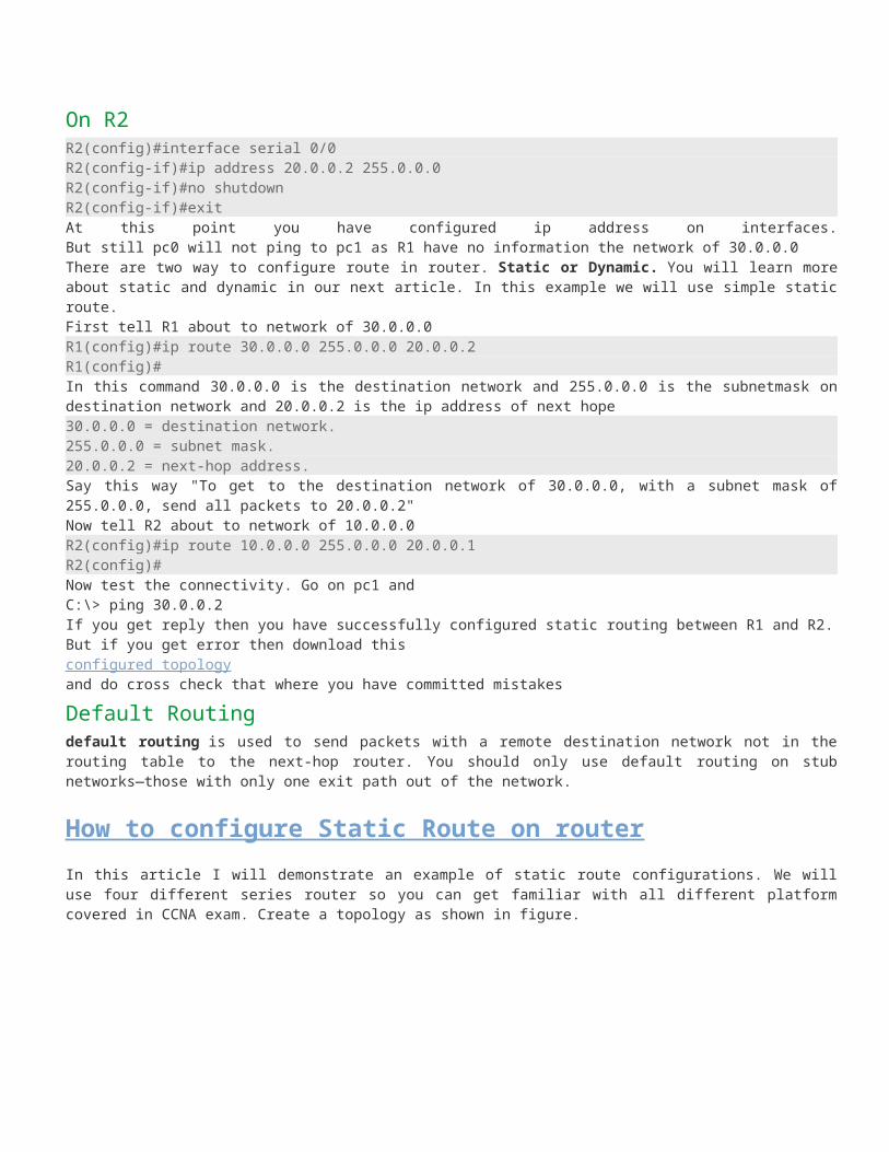
Now configure PC-0 first.To configure pc double click on pc and select desktop Now click on IP configurations

Set ip address as shown in figure
IP address 10.0.0.2 Subnet mask 255.0.0.0 Default Gateway 10.0.0.1 Follow the same process in PC-1 and set the ip address to IP address 30.0.0.2 Subnet mask 255.0.0.0 Default Gateway 30.0.0.1 Now double click on 1841 Router 0 and select CLI
Type no and press enter to avoid startup configuration Now you are in user exec mode. --- System Configuration Dialog ---
Continue with configuration dialog? [yes/no]: no
Press RETURN to get started!
Router>Set Hostname to R1 and assign 10.0.0.1 255.0.0.0 ip address to fast Ethernet 0/0. also set a message “ Unauthorized access is prohibited”.Router>enableRouter#configure terminalEnter configuration commands, one per line. End with CNTL/Z.Router(config)#hostname R1

R1(config)#banner motd # Unauthorized access is prohibited #R1(config)#interface fastethernet 0/0R1(config-if)#ip address 10.0.0.1 255.0.0.0R1(config-if)#no shutdown%LINK-5-CHANGED: Interface FastEthernet0/0, changed state to upR1(config-if)#exitR1(config)#Configure Router-2 in same way with hostname R2 and 30.0.0.1 255.0.0.0 ip address on fast Ethernet 0/0.Router>enableRouter#configure terminalEnter configuration commands, one per line. End with CNTL/Z.Router(config)#hostname R2R2(config)#interface fastEthernet 0/0R2(config-if)#ip address 30.0.0.1 255.0.0.0R2(config-if)#no shutdown%LINK-5-CHANGED: Interface FastEthernet0/0, changed state to up%LINEPROTO-5-UPDOWN: Line protocol on Interface FastEthernet0/0, changed state to upR2(config-if)#exitR2(config)#Now we have connectivity between local segment and router's Ethernet port.
configure serial portWhen Serial connections are configured they need one more command that normal Ethernet connections do not. That command is the clock rate command. The clock rate command establishes a common rate at which the sending and receiving routers will send data to each other. It should be noted that if using a service provider circuit, there is no need for the clock rate command since the service provider provides the clocking. Establish a simple serial to serial connection between R1 Serial 0/0/0 and R2 Serial 0/0/0.Now configure serial port on both router with ip address 20.0.0.1 255.0.0.0 on one and 20.0.0.2 255.0.0.0 on two.
On R1R1(config)#interface serial 0/0/0R1(config-if)#ip address 20.0.0.1 255.0.0.0R1(config-if)#clock rate 64000R1(config-if)#bandwidth 64R1(config-if)#no shutdown%LINK-5-CHANGED: Interface Serial0/0/0, changed state to up%LINEPROTO-5-UPDOWN: Line protocol on Interface Serial0/0/0, changed state to upR1(config-if)#exitR1(config)#
On R2R2(config)#interface serial 0/0R2(config-if)#ip address 20.0.0.2 255.0.0.0R2(config-if)#no shutdownR2(config-if)#exitAt this point you have configured ip address on interfaces.But still pc0 will not ping to pc1 as R1 have no information the network of 30.0.0.0There are two way to configure route in router. Static or Dynamic. You will learn more about static and dynamic in our next article. In this example we will use simple static route.First tell R1 about to network of 30.0.0.0R1(config)#ip route 30.0.0.0 255.0.0.0 20.0.0.2R1(config)#
In this command 30.0.0.0 is the destination network and 255.0.0.0 is the subnetmask on destination network and 20.0.0.2 is the ip address of next hope30.0.0.0 = destination network.255.0.0.0 = subnet mask.20.0.0.2 = next-hop address.Say this way "To get to the destination network of 30.0.0.0, with a subnet mask of 255.0.0.0, send all packets to 20.0.0.2"Now tell R2 about to network of 10.0.0.0R2(config)#ip route 10.0.0.0 255.0.0.0 20.0.0.1R2(config)#Now test the connectivity. Go on pc1 and C:\> ping 30.0.0.2If you get reply then you have successfully configured static routing between R1 and R2.But if you get error then download thisconfigured topologyand do cross check that where you have committed mistakes
Default Routingdefault routing is used to send packets with a remote destination network not in the routing table to the next-hop router. You should only use default routing on stub networks—those with only one exit path out of the network.
How to configure Static Route on routerIn this article I will demonstrate an example of static route configurations. We will use four different series router so you can get familiar with all different platform covered in CCNA exam. Create a topology as shown in figure.
A static route is a manually configured route on your router. Static routes are typically used in smaller networks and when few networks or subnets exist, or with WAN links that have little available bandwidth. With a network that has hundreds of routes, static routes are not scalable, since you would have to configure each route and any redundant paths for that route on each router.1841 Series Router0 (R1)
FastEthernet0/0 Serial0/0/0
IP address 10.0.0.1 20.0.0.1

Connected With Pc0 R2 on Serial
0/02811 Series Router0 (R4)
FastEthernet0/0 Serial0/0/0
IP address 50.0.0.1 40.0.0.2
Connected With Pc1 R3 on Serial
0/02621XM Series Router0 (R3)
FastEthernet0/0 Serial0/0/0
IP address 30.0.0.2 40.0.0.1
Connected With FastEthernet0/0 R4 on Serial
0/0/02620XM Series Router1 (R2)
FastEthernet0/0 Serial0/0
IP address 30.0.0.1 20.0.0.2
Connected With
R3 on FastEthernet0/0
R1 on Serial 0/0/0
PC-PT PC0
FastEthernet0 Default Gateway
IP address 10.0.0.2 10.0.0.1
Connected With
R1 on FastEthernet0/0
PC-PT PC1
FastEthernet0 Default Gateway
IP address 50.0.0.2 50.0.0.1
Connected With
R4 on FastEthernet0/0
To configure any router double click on it and select CLI.To configure this topology use this step by step guide.
(1841Router0) Hostname R1To configure and enable static routing on R1 follow these commands exactly.Router>enableRouter#configure terminalEnter configuration commands, one per line. End with CNTL/Z.Router(config)#hostname R1R1(config)#interface fastethernet 0/0

R1(config-if)#ip address 10.0.0.1 255.0.0.0R1(config-if)#no shutdown%LINK-5-CHANGED: Interface FastEthernet0/0, changed state to up%LINEPROTO-5-UPDOWN: Line protocol on Interface FastEthernet0/0, changed state to upR1(config-if)#exitR1(config)#interface serial 0/0/0R1(config-if)#ip address 20.0.0.1 255.0.0.0R1(config-if)#clock rate 64000R1(config-if)#bandwidth 64R1(config-if)#no shutdown%LINK-5-CHANGED: Interface Serial0/0/0, changed state to downR1(config-if)#exit%LINK-5-CHANGED: Interface Serial0/0/0, changed state to upR1(config)#ip route 30.0.0.0 255.0.0.0 20.0.0.2R1(config)#ip route 40.0.0.0 255.0.0.0 20.0.0.2R1(config)#ip route 50.0.0.0 255.0.0.0 20.0.0.2
(2620XM-Router1) Hostname R2To configure and enable static routing on R2 follow these commands exactly.Router>enableRouter#configure terminalEnter configuration commands, one per line. End with CNTL/Z.Router(config)#hostname R2R2(config)#interface serial 0/0R2(config-if)#ip address 20.0.0.2 255.0.0.0R2(config-if)#no shutdown%LINK-5-CHANGED: Interface Serial0/0, changed state to up%LINEPROTO-5-UPDOWN: Line protocol on Interface Serial0/0, changed state to upR2(config-if)#exitR2(config)#interface fastethernet 0/0R2(config-if)#ip address 30.0.0.1 255.0.0.0R2(config-if)#no shutdown%LINK-5-CHANGED: Interface FastEthernet0/0, changed state to upR2(config-if)#exit%LINEPROTO-5-UPDOWN: Line protocol on Interface FastEthernet0/0, changed state to upR2(config)#ip route 10.0.0.0 255.0.0.0 20.0.0.1R2(config)#ip route 40.0.0.0 255.0.0.0 30.0.0.2R2(config)#ip route 50.0.0.0 255.0.0.0 30.0.0.2
(2620XM-Router2)Hostname R3To configure and enable static routing on R3 follow these commands exactly.Router>enableRouter#configure terminalEnter configuration commands, one per line. End with CNTL/Z.Router(config)#hostname R3R3(config)#interface fastethernet 0/0R3(config-if)#ip address 30.0.0.2 255.0.0.0R3(config-if)#no shutdown%LINK-5-CHANGED: Interface FastEthernet0/0, changed state to up%LINEPROTO-5-UPDOWN: Line protocol on Interface FastEthernet0/0, changed state to upR3(config-if)#interface serial 0/0R3(config-if)#ip address 40.0.0.1 255.0.0.0R3(config-if)#clock rate 64000R3(config-if)#bandwidth 64R3(config-if)#no shutdown%LINK-5-CHANGED: Interface Serial0/0, changed state to down
R3(config-if)#exit%LINK-5-CHANGED: Interface Serial0/0, changed state to up%LINEPROTO-5-UPDOWN: Line protocol on Interface Serial0/0, changed state to upR3(config)#ip route 10.0.0.0 255.0.0.0 30.0.0.1R3(config)#ip route 20.0.0.0 255.0.0.0 30.0.0.1R3(config)#ip route 50.0.0.0 255.0.0.0 40.0.0.2
(2811Router3) Hostname R4To configure and enable static routing on R4 follow these commands exactly.Router>enableRouter#configure terminalEnter configuration commands, one per line. End with CNTL/Z.Router(config)#interface serial 0/0/0Router(config-if)#ip address 40.0.0.2 255.0.0.0Router(config-if)#no shutdown%LINK-5-CHANGED: Interface Serial0/0/0, changed state to up%LINEPROTO-5-UPDOWN: Line protocol on Interface Serial0/0/0, changed state to upRouter(config-if)#exitRouter(config)#interface fastethernet 0/0Router(config-if)#ip address 50.0.0.1 255.0.0.0Router(config-if)#no shutdown%LINK-5-CHANGED: Interface FastEthernet0/0, changed state to up%LINEPROTO-5-UPDOWN: Line protocol on Interface FastEthernet0/0, changed state to upRouter(config-if)#exitRouter(config)#ip route 10.0.0.0 255.0.0.0 40.0.0.1Router(config)#ip route 20.0.0.0 255.0.0.0 40.0.0.1Router(config)#ip route 30.0.0.0 255.0.0.0 40.0.0.1
PC-1PC>ipconfig
IP Address......................: 10.0.0.2Subnet Mask.....................: 255.0.0.0Default Gateway.................: 10.0.0.1
PC>ping 50.0.0.2
Pinging 50.0.0.2 with 32 bytes of data:
Reply from 50.0.0.2: bytes=32 time=156ms TTL=124Reply from 50.0.0.2: bytes=32 time=127ms TTL=124Reply from 50.0.0.2: bytes=32 time=156ms TTL=124Reply from 50.0.0.2: bytes=32 time=140ms TTL=124
Ping statistics for 50.0.0.2: Packets: Sent = 4, Received = 4, Lost = 0 (0% loss),Approximate round trip times in milli-seconds: Minimum = 127ms, Maximum = 156ms, Average = 144msPC>
PC-2PC>ipconfig
IP Address......................: 50.0.0.2Subnet Mask.....................: 255.0.0.0Default Gateway.................: 50.0.0.1

PC>ping 10.0.0.2
Pinging 10.0.0.2 with 32 bytes of data:
Reply from 10.0.0.2: bytes=32 time=140ms TTL=124Reply from 10.0.0.2: bytes=32 time=141ms TTL=124Reply from 10.0.0.2: bytes=32 time=157ms TTL=124Reply from 10.0.0.2: bytes=32 time=156ms TTL=124
Ping statistics for 10.0.0.2: Packets: Sent = 4, Received = 4, Lost = 0 (0% loss),Approximate round trip times in milli-seconds: Minimum = 140ms, Maximum = 157ms, Average = 148msTo test static routing do ping from pc1 to pc2 and vice versa. If you get replay then you have successfully configured static routing but if you did not get replay double check this configuration and try to troubleshoot. I have uploaded a configured and tested topology in case you are unable to locate the problem spot then download this configuration file. And try to find out where have you committed mistakestatic route configurations
RIP Routing information protocolRouting Information Protocol (RIP) is a standards-based, distance-vector, interior gateway protocol (IGP) used by routers to exchange routing information. RIP uses hop count to determine the best path between two locations. Hop count is the number of routers the packet must go through till it reaches the destination network. The maximum allowable number of hops a packet can traverse in an IP network implementing RIP is 15 hops.it has a maximum allowable hop count of 15 by default, meaning that 16 is deemed unreachable. RIP works well in small networks, but it's inefficient on large networks with slow WAN links or on networks with a large number of routers installed.In a RIP network, each router broadcasts its entire RIP table to its neighboring routers every 30 seconds. When a router receives a neighbor's RIP table, it uses the information provided to update its own routing table and then sends the updated table to its neighbors.
Differences between RIPv1 or RIPv2RIPv1 A classful protocol, broadcasts updates every 30 seconds, hold-down period 180 seconds. Hop count is metric
(Maximum 15). RIP supports up to six equal-cost paths to a single destination, where all six paths can be placed in the routing table
and the router can load-balance across them. The default is actually four paths, but this can be increased up to a maximum of six. Remember that an equal-cost path is where the hop count value is the same. RIP will not load-balance across unequal-cost paths
RIPv2 RIPv2 uses multicasts, version 1 use broadcasts, RIPv2 supports triggered updates—when a change occurs, a RIPv2 router will immediately propagate its routing
information to its connected neighbors. RIPv2 is a classless protocol. RIPv2 supports variable-length subnet masking (VLSM)
RIPv2 supports authentication. You can restrict what routers you want to participate in RIPv2. This is accomplished using a hashed password value.
RIP TimersRIP uses four different kinds of timers to regulate its performance:
Route update timerSets the interval (typically 30 seconds) between periodic routing updates in which the router sends a complete copy of its routing table out to all neighbors.
Route invalid timerDetermines the length of time that must elapse (180 seconds) before a router determines that a route has become invalid. It will come to this conclusion if it hasn’t heard any updates about a particular route for that period. When that happens, the router will send out updates to all its neighbors letting them know that the route is invalid.
Holddown timerThis sets the amount of time during which routing information is suppressed. Routes will enter into the holddown state when an update packet is received that indicated the route is unreachable. This continues either until an update packet is received with a better metric or until the holddown timer expires. The default is 180 seconds.
Route flush timerSets the time between a route becoming invalid and its removal from the routing table (240 seconds). Before it's removed from the table, the router notifies its neighbors of that route's impending failure. The value of the route invalid timer must be less than that of the route flush timer. This gives the router enough time to tell its neighbors about the invalid route before the local routing table is updated.
Rip Routing configurationsWe will use two router and four subnet. Create a topology as shown in figure on packet tracer.
Router FastEthernet 0/0 FastEthernet 0/1 Serial 0/0/0

R1 10.0.0.1 20.0.0.1 50.0.0.1
R2 30.0.0.1 40.0.0.1 50.0.0.2
PC IP Address PC IP Address
PC0 20.0.0.2 PC1 20.0.0.3
PC2 40.0.0.2 PC3 40.0.0.3
PC4 10.0.0.2 PC5 10.0.0.3
PC6 30.0.0.2 PC7 30.0.0.3
Assign ip address to PC. Select pc and double click on it. select ip configurations from desktop tab and set ip address given as in table.To configure router double click on it and select CLI.To configure this topology use this step by step guide.
(1841Router0) Hostname R1To configure and enable rip routing on R1 follow these commands exactly.Router>enableRouter#configure terminalEnter configuration commands, one per line. End with CNTL/Z.Router(config)#hostname R1R1(config)#interface fastethernet 0/0R1(config-if)#ip address 10.0.0.1 255.0.0.0R1(config-if)#no shutdown%LINK-5-CHANGED: Interface FastEthernet0/0, changed state to up%LINEPROTO-5-UPDOWN: Line protocol on Interface FastEthernet0/0, changed state to upR1(config-if)#exitR1(config)#interface fastethernet 0/1R1(config-if)#ip address 20.0.0.1 255.0.0.0R1(config-if)#no shutdown%LINK-5-CHANGED: Interface FastEthernet0/1, changed state to up%LINEPROTO-5-UPDOWN: Line protocol on Interface FastEthernet0/1, changed state to upR1(config-if)#exitR1(config)#interface serial 0/0/0R1(config-if)#ip address 50.0.0.1 255.0.0.0R1(config-if)#clock rate 64000R1(config-if)#bandwidth 64R1(config-if)#no shutdown%LINK-5-CHANGED: Interface Serial0/0/0, changed state to downR1(config-if)#exitR1(config)#router ripR1(config-router)#network 10.0.0.0R1(config-router)#network 20.0.0.0R1(config-router)#network 50.0.0.0
(2811Router1) Hostname R2To configure and enable rip routing on R2 follow these commands exactly.Router>enableRouter#configure terminalEnter configuration commands, one per line. End with CNTL/Z.Router(config)#hostname R2R2(config)#interface fastethernet 0/0R2(config-if)#ip address 30.0.0.1 255.0.0.0

R2(config-if)#no shutdown%LINK-5-CHANGED: Interface FastEthernet0/0, changed state to up%LINEPROTO-5-UPDOWN: Line protocol on Interface FastEthernet0/0, changed state to upR2(config-if)#exitR2(config)#interface fastethernet 0/1R2(config-if)#ip address 40.0.0.1 255.0.0.0R2(config-if)#no shutdown%LINK-5-CHANGED: Interface FastEthernet0/1, changed state to up%LINEPROTO-5-UPDOWN: Line protocol on Interface FastEthernet0/1, changed state to upR2(config-if)#exitR2(config)#interface serial 0/0/0R2(config-if)#ip address 50.0.0.2 255.0.0.0R2(config-if)#no shutdown%LINK-5-CHANGED: Interface Serial0/0/0, changed state to upR2(config-if)#%LINEPROTO-5-UPDOWN: Line protocol on Interface Serial0/0/0, changed state to upR2(config-if)#exitR2(config)#router ripR2(config-router)#network 30.0.0.0R2(config-router)#network 40.0.0.0R2(config-router)#network 50.0.0.0R2(config-router)#exitTo test rip routing do ping from pc0 to all pc and vice versa. If you get replay then you have successfully configured rip routing but if you did not get replay double check this configuration and try to troubleshoot. I have uploaded a configured and tested topology in case you are unable to locate the problem spot then download this configuration file. And try to find out where have you committed mistakerip routing configurationsIn our next article we will learn advance configuration of RIP routing.
How to configure RIP Routing information protocolIn this article I will demonstrate an example of Rip Routing configurations. We will use four different series router so you can get familiar with all different platform covered in CCNA exam. Create a topology as shown in figure.

IP RIP comes in two different versions: 1 and 2. Version 1 is a distance vector protocol and is defined in RFC 1058. Version 2 is a hybrid protocol and is defined in RFCs 1721 and 1722. The CCNA exam now primarily focuses on version 2. There are no major differences between RIPv1 or RIPv2 so far configurations concern. To read more about differences between RIPv1 or RIPv2 or know about the characteristics read our pervious article about RIP.1841 Series Router0 (R1)
FastEthernet0/0 Serial0/0/0
IP address 10.0.0.1 20.0.0.1
Connected With Pc0 R2 on Serial
0/02811 Series Router0 (R4)
FastEthernet0/0 Serial0/0/0
IP address 50.0.0.1 40.0.0.2
Connected With Pc1 R3 on Serial
0/02621XM Series Router0 (R3)
FastEthernet0/0 Serial0/0/0
IP address 30.0.0.2 40.0.0.1
Connected With FastEthernet0/0 R4 on Serial
0/0/02620XM Series Router1 (R2)
FastEthernet0/0 Serial0/0
IP address 30.0.0.1 20.0.0.2
Connected With
R3 on FastEthernet0/0
R1 on Serial 0/0/0

PC-PT PC0
FastEthernet0 Default Gateway
IP address 10.0.0.2 10.0.0.1
Connected With
R1 on FastEthernet0/0
PC-PT PC1
FastEthernet0 Default Gateway
IP address 50.0.0.2 50.0.0.1
Connected With
R4 on FastEthernet0/0
To configure any router double click on it and select CLI. To configure this topology use this step by step guide.
(1841Router0) Hostname R1To configure and enable rip routing on R1 follow these commands exactly.Router>enableRouter#configure terminalEnter configuration commands, one per line. End with CNTL/Z.Router(config)#hostname R1R1(config)#interface fastethernet 0/0R1(config-if)#ip address 10.0.0.1 255.0.0.0R1(config-if)#no shutdown%LINK-5-CHANGED: Interface FastEthernet0/0, changed state to up%LINEPROTO-5-UPDOWN: Line protocol on Interface FastEthernet0/0, changed state to upR1(config-if)#exitR1(config)#interface serial 0/0/0R1(config-if)#ip address 20.0.0.1 255.0.0.0R1(config-if)#clock rate 64000R1(config-if)#bandwidth 64R1(config-if)#no shutdown%LINK-5-CHANGED: Interface Serial0/0/0, changed state to downR1(config-if)#exit%LINK-5-CHANGED: Interface Serial0/0/0, changed state to upR1(config)#router ripR1(config-router)#network 10.0.0.0R1(config-router)#network 20.0.0.0R1(config-router)#exitR1(config)#
(2620XM-Router1) Hostname R2To configure and enable rip routing on R2 follow these commands exactly.Router>enableRouter#configure terminalEnter configuration commands, one per line. End with CNTL/Z.Router(config)#hostname R2R2(config)#interface serial 0/0R2(config-if)#ip address 20.0.0.2 255.0.0.0R2(config-if)#no shutdown

%LINK-5-CHANGED: Interface Serial0/0, changed state to up%LINEPROTO-5-UPDOWN: Line protocol on Interface Serial0/0, changed state to upR2(config-if)#exitR2(config)#interface fastethernet 0/0R2(config-if)#ip address 30.0.0.1 255.0.0.0R2(config-if)#no shutdown%LINK-5-CHANGED: Interface FastEthernet0/0, changed state to upR2(config-if)#exit%LINEPROTO-5-UPDOWN: Line protocol on Interface FastEthernet0/0, changed state to upR2(config)#router ripR2(config-router)#network 20.0.0.0R2(config-router)#network 30.0.0.0R2(config-router)#exitR2(config)#
(2620XM-Router2)Hostname R3To configure and enable rip routing on R3 follow these commands exactly.Router>enableRouter#configure terminalEnter configuration commands, one per line. End with CNTL/Z.Router(config)#hostname R3R3(config)#interface fastethernet 0/0R3(config-if)#ip address 30.0.0.2 255.0.0.0R3(config-if)#no shutdown%LINK-5-CHANGED: Interface FastEthernet0/0, changed state to up%LINEPROTO-5-UPDOWN: Line protocol on Interface FastEthernet0/0, changed state to upR3(config-if)#interface serial 0/0R3(config-if)#ip address 40.0.0.1 255.0.0.0R3(config-if)#clock rate 64000R3(config-if)#bandwidth 64R3(config-if)#no shutdown%LINK-5-CHANGED: Interface Serial0/0, changed state to downR3(config-if)#exit%LINK-5-CHANGED: Interface Serial0/0, changed state to up%LINEPROTO-5-UPDOWN: Line protocol on Interface Serial0/0, changed state to upR3(config)#router ripR3(config-router)#network 30.0.0.0R3(config-router)#network 40.0.0.0R3(config-router)#exitR3(config)#
(2811Router3) Hostname R4To configure and enable rip routing on R4 follow these commands exactly.Router>enableRouter#configure terminalEnter configuration commands, one per line. End with CNTL/Z.Router(config)#interface serial 0/0/0Router(config-if)#ip address 40.0.0.2 255.0.0.0Router(config-if)#no shutdown%LINK-5-CHANGED: Interface Serial0/0/0, changed state to up%LINEPROTO-5-UPDOWN: Line protocol on Interface Serial0/0/0, changed state to upRouter(config-if)#exitRouter(config)#interface fastethernet 0/0Router(config-if)#ip address 50.0.0.1 255.0.0.0Router(config-if)#no shutdown%LINK-5-CHANGED: Interface FastEthernet0/0, changed state to up

%LINEPROTO-5-UPDOWN: Line protocol on Interface FastEthernet0/0, changed state to upRouter(config-if)#exitR4(config)#router ripR4(config-router)#network 40.0.0.0R4(config-router)#network 50.0.0.0R4(config-router)#exitR4(config)#
PC-1PC>ipconfig
IP Address......................: 10.0.0.2Subnet Mask.....................: 255.0.0.0Default Gateway.................: 10.0.0.1
PC>ping 50.0.0.2
Pinging 50.0.0.2 with 32 bytes of data:
Reply from 50.0.0.2: bytes=32 time=156ms TTL=124Reply from 50.0.0.2: bytes=32 time=127ms TTL=124Reply from 50.0.0.2: bytes=32 time=156ms TTL=124Reply from 50.0.0.2: bytes=32 time=140ms TTL=124
Ping statistics for 50.0.0.2: Packets: Sent = 4, Received = 4, Lost = 0 (0% loss),Approximate round trip times in milli-seconds: Minimum = 127ms, Maximum = 156ms, Average = 144msPC>
PC-2PC>ipconfig
IP Address......................: 50.0.0.2Subnet Mask.....................: 255.0.0.0Default Gateway.................: 50.0.0.1
PC>ping 10.0.0.2
Pinging 10.0.0.2 with 32 bytes of data:
Reply from 10.0.0.2: bytes=32 time=140ms TTL=124Reply from 10.0.0.2: bytes=32 time=141ms TTL=124Reply from 10.0.0.2: bytes=32 time=157ms TTL=124Reply from 10.0.0.2: bytes=32 time=156ms TTL=124
Ping statistics for 10.0.0.2: Packets: Sent = 4, Received = 4, Lost = 0 (0% loss),Approximate round trip times in milli-seconds: Minimum = 140ms, Maximum = 157ms, Average = 148msYou can verify that RIP is running successfully via show ip protocols command in privilege mode.R1#show ip protocolsRouting Protocol is "rip"Sending updates every 30 seconds, next due in 2 secondsInvalid after 180 seconds, hold down 180, flushed after 240Outgoing update filter list for all interfaces is not set

Incoming update filter list for all interfaces is not setRedistributing: ripDefault version control: send version 1, receive any version Interface Send Recv Triggered RIP Key-chain FastEthernet0/0 1 2 1 Serial0/0/0 1 2 1Automatic network summarization is in effectMaximum path: 4Routing for Networks:
10.0.0.020.0.0.0
Passive Interface(s):Routing Information Sources:
Gateway Distance Last Update20.0.0.2 120 00:00:20
Distance: (default is 120)R1#You can use show ip route command to troubleshoot rip network. If you did not see information about any route checks the router attached with that network.R1#show ip routeCodes: C - connected, S - static, I - IGRP, R - RIP, M - mobile, B - BGP D - EIGRP, EX - EIGRP external, O - OSPF, IA - OSPF inter area N1 - OSPF NSSA external type 1, N2 - OSPF NSSA external type 2 E1 - OSPF external type 1, E2 - OSPF external type 2, E - EGP i - IS-IS, L1 - IS-IS level-1, L2 - IS-IS level-2, ia - IS-IS inter area * - candidate default, U - per-user static route, o - ODR P - periodic downloaded static route
Gateway of last resort is not set
C 10.0.0.0/8 is directly connected, FastEthernet0/0C 20.0.0.0/8 is directly connected, Serial0/0/0R 30.0.0.0/8 [120/1] via 20.0.0.2, 00:00:01, Serial0/0/0R 40.0.0.0/8 [120/2] via 20.0.0.2, 00:00:01, Serial0/0/0R 50.0.0.0/8 [120/3] via 20.0.0.2, 00:00:01, Serial0/0/0R1#To test rip routing do ping from pc1 to pc2 and vice versa. If you get replay then you have successfully configured rip routing but if you did not get replay double check this configuration and try to troubleshoot. I have uploaded a configured and tested topology in case you are unable to locate the problem spot then download this configuration file. And try to find out where have you committed mistakerip routing configurations
Configure RIP Routing command cheat sheetCommands Descriptions
Router(config)#router rip Enables RIP as a routing protocol
Router(config-router)#network w.x.y.zw.x.y.z is the network number of the directly connected network
you want to advertise.
Router(config)#no router rip Turns off the RIP routing process

Router(config-router)#no network w.x.y.z Removes network w.x.y.z from the RIP routing process.
Router(config-router)#version 2 RIP will now send and receive RIPv2 packets globally.
Router(config-router)#version 1 RIP will now send and receive RIPv1 packets only
Router(config-router)#no auto-summaryRIPv2 summarizes networks at the classful boundary. This
command turns autosummarization off.
Router(config-router)#passive-interface s0/0/0 RIP updates will not be sent out this interface.
Router(config-router)#no ip split-horizon Turns off split horizon (on by default).
Router(config-router)#ip split-horizon Re-enables split horizon
Router(config-router)#timers basic 30 90 180 270
360
Changes timers in RIP: 30 = Update timer (in seconds) 90 =
Invalid timer (in seconds) 180 = Hold-down timer (in seconds)
270 = Flush timer (in seconds) 360 = Sleep time (in
milliseconds)
Router#debug ip rip Displays all RIP activity in real time
Router#show ip rip database Displays contents of the RIP database
Enhanced Interior Gateway Routing Protocol ConfigurationsEIGRP is the advance version of Cisco's earlier version IGRP. Before you learn more about EIGRP let be familiar with IGRP.
Interior Gateway Routing Protocol (IGRP)The Interior Gateway Routing Protocol (IGRP) is a Cisco-proprietary routing protocol for IP. it is a distance vector protocol. It uses a sophisticated metric based on bandwidth and delay. It uses triggered updates to speed-up convergence. It supports unequal-cost load balancing to a single destination.IGRP is Cisco proprietary uses bandwidth, delay, reliability, load, and MTU as its metrics (bandwidth and delay be default).IGRP's routing update period is every 90 seconds. Its hold-down period is 280 seconds, and its flush period is 630 seconds.It also supports triggered updates and load balancing across unequal-cost paths.IGRP requires an AS number in its router command; plus, when entering network numbers for the network command, they are entered as the classful network number, as they are for RIP.

IGRP supports both equal- and unequal-cost paths for load balancing to single destination Equal-cost paths are enabled by default, where IGRP supports up to six equal-cost paths (four by default) to a single destination in the IP routing table. IGRP, however, also supports unequal-cost paths, but this feature is disabled by default.
Enhanced Interior Gateway Routing ProtocolThe Enhanced Interior Gateway Routing Protocol (EIGRP) is a Cisco-proprietary routing protocol for IP. These characteristics include:
Fast convergence
Loop-free topology
VLSM and route summarization
Multicast and incremental updates
Routes for multiple routed protocolsHere is a brief comparison of EIGRP and IGRP:
Both offer load balancing across six paths (equal or unequal). They have similar metric structures. EIGRP has faster convergence (triggered updates and saving a neighbor's routing table locally). EIGRP has less network overhead, since it uses incremental updates. Interesting point about these protocols is that if you have some routers in your network running IGRP and
others running EIGRP and both sets have the same autonomous system number, routing information will automatically be shared between the two.
EIGRP uses a 32-bit metric, while IGRP uses a 24-bit metric.
EIGRP uses the Diffusing Update Algorithm (DUAL) to update the routing table.
One really unique feature of EIGRP is that it supports three routed protocols: IP, IPX, and AppleTalk
Hello packets are generated every five seconds on LAN interfaces as multicasts (224.0.0.10). For EIGRP routers to become neighbors, the following information must match: The AS number The K-values (these enable/disable the different metric components)
When two routers determine whether they will become neighbors, they go through the following process: The first router generates a Hello with configuration information. If the configuration information matches, the second router responds with an Update message with topology
information. The first router responds with an ACK message, acknowledging the receipt of the second's ACK. The first router sends its topology to the second router via an Update message. The second router responds back with an ACK.You must specify the AS number when configure EIGRP. Even though EIGRP is classless, you must configure it as a classful protocol when specifying your network numbers with the network command.
EIGRP TermsTerm Definition
Successor The best path to reach a destination within the topology table.
Feasible successorThe best backup path to reach a destination within the topology table—multiple successors can
be feasible for a particular destination.
Routing tableThis is all of the successor routes from the topology table. There is a separate routing table for
each routed protocol.
Advertised distance The distance (metric) that a neighboring router is advertising for a specific route.
Feasible distanceThe distance (metric) that your router has computed to reach a specific route: the advertised
distance from the neighboring router plus the local router's interface metric.
Neighbor table
Contains a list of the EIGRP neighbors and is similar to the adjacencies that are built in OSPF
between the designated router/backup DR and the other routers on a segment. Each routed
protocol (IP, IPX, and AppleTalk) for EIGRP has its own neighbor table.
Topology table
Similar to OSPF's database, contains a list of all destinations and paths the EIGRP router
learned—it is basically a compilation of the neighboring routers' routing tables. A separate
topology table exists for each routed protocol.
How to configure enhanced interior gateway routing protocolEIGRP is a Cisco-proprietary routing protocol for TCP/IP. It's actually based on Cisco's proprietary IGRP routing protocol, with many enhancements built into it. Because it has its roots in IGRP, the configuration is similar to IGRP; however, it has many link state characteristics that were added to it to allow EIGRP to scale to enterprise network sizes. To know these characteristics read our previous article.In this article I will demonstrate an example of EIGRP Routing configurations. We will use four different series router so you can get familiar with all different platform covered in CCNA exam. Create a topology as shown in figure.

1841 Series Router0 (R1)FastEthernet0/0 Serial0/0/0
IP address 10.0.0.1 20.0.0.1
Connected With Pc0 R2 on Serial 0/0
2811 Series Router0 (R4)FastEthernet0/0 Serial0/0/0
IP address 50.0.0.1 40.0.0.2
Connected With Pc1 R3 on Serial 0/0
2621XM Series Router0 (R3)FastEthernet0/0 Serial0/0/0
IP address 30.0.0.2 40.0.0.1
Connected With FastEthernet0/0 R4 on Serial 0/0/0
2620XM Series Router1 (R2)FastEthernet0/0 Serial0/0
IP address 30.0.0.1 20.0.0.2
Connected With R3 on FastEthernet0/0 R1 on Serial 0/0/0
PC-PT PC0
FastEthernet0 Default Gateway
IP address 10.0.0.2 10.0.0.1
Connected With R1 on FastEthernet0/0

PC-PT PC1
FastEthernet0 Default Gateway
IP address 50.0.0.2 50.0.0.1
Connected With R4 on FastEthernet0/0
To configure any router double click on it and select CLI.To configure this topology use this step by step guide.
(1841Router0) Hostname R1To configure and enable eigrp routing on R1 follow these commands exactly.Router>enableRouter#configure terminalEnter configuration commands, one per line. End with CNTL/Z.Router(config)#hostname R1R1(config)#interface fastethernet 0/0R1(config-if)#ip address 10.0.0.1 255.0.0.0R1(config-if)#no shutdown%LINK-5-CHANGED: Interface FastEthernet0/0, changed state to up%LINEPROTO-5-UPDOWN: Line protocol on Interface FastEthernet0/0, changed state to upR1(config-if)#exitR1(config)#interface serial 0/0/0R1(config-if)#ip address 20.0.0.1 255.0.0.0R1(config-if)#clock rate 64000R1(config-if)#bandwidth 64R1(config-if)#no shutdown%LINK-5-CHANGED: Interface Serial0/0/0, changed state to downR1(config-if)#exit%LINK-5-CHANGED: Interface Serial0/0/0, changed state to upR1(config)#router eigrp 1R1(config-router)#network 10.0.0.0R1(config-router)#network 20.0.0.0R1(config-router)#exitR1(config)#
(2620XM-Router1) Hostname R2To configure and enable eigrp routing on R2 follow these commands exactly.Router>enableRouter#configure terminalEnter configuration commands, one per line. End with CNTL/Z.Router(config)#hostname R2R2(config)#interface serial 0/0R2(config-if)#ip address 20.0.0.2 255.0.0.0R2(config-if)#no shutdown%LINK-5-CHANGED: Interface Serial0/0, changed state to up%LINEPROTO-5-UPDOWN: Line protocol on Interface Serial0/0, changed state to upR2(config-if)#exitR2(config)#interface fastethernet 0/0R2(config-if)#ip address 30.0.0.1 255.0.0.0R2(config-if)#no shutdown%LINK-5-CHANGED: Interface FastEthernet0/0, changed state to upR2(config-if)#exit%LINEPROTO-5-UPDOWN: Line protocol on Interface FastEthernet0/0, changed state to upR2(config)#router eigrp 1R2(config-router)#network 20.0.0.0

R2(config-router)#network 30.0.0.0R2(config-router)#exitR2(config)#
(2620XM-Router2)Hostname R3To configure and enable eigrp routing on R3 follow these commands exactly.Router>enableRouter#configure terminalEnter configuration commands, one per line. End with CNTL/Z.Router(config)#hostname R3R3(config)#interface fastethernet 0/0R3(config-if)#ip address 30.0.0.2 255.0.0.0R3(config-if)#no shutdown%LINK-5-CHANGED: Interface FastEthernet0/0, changed state to up%LINEPROTO-5-UPDOWN: Line protocol on Interface FastEthernet0/0, changed state to upR3(config-if)#interface serial 0/0R3(config-if)#ip address 40.0.0.1 255.0.0.0R3(config-if)#clock rate 64000R3(config-if)#bandwidth 64R3(config-if)#no shutdown%LINK-5-CHANGED: Interface Serial0/0, changed state to downR3(config-if)#exit%LINK-5-CHANGED: Interface Serial0/0, changed state to up%LINEPROTO-5-UPDOWN: Line protocol on Interface Serial0/0, changed state to upR3(config)#router eigrp 1R3(config-router)#network 30.0.0.0R3(config-router)#network 40.0.0.0R3(config-router)#exitR3(config)#
(2811Router3) Hostname R4To configure and enable eigrp routing on R4 follow these commands exactly.Router>enableRouter#configure terminalEnter configuration commands, one per line. End with CNTL/Z.Router(config)#interface serial 0/0/0Router(config-if)#ip address 40.0.0.2 255.0.0.0Router(config-if)#no shutdown%LINK-5-CHANGED: Interface Serial0/0/0, changed state to up%LINEPROTO-5-UPDOWN: Line protocol on Interface Serial0/0/0, changed state to upRouter(config-if)#exitRouter(config)#interface fastethernet 0/0Router(config-if)#ip address 50.0.0.1 255.0.0.0Router(config-if)#no shutdown%LINK-5-CHANGED: Interface FastEthernet0/0, changed state to up%LINEPROTO-5-UPDOWN: Line protocol on Interface FastEthernet0/0, changed state to upRouter(config-if)#exitR3(config)#router eigrp 1R3(config-router)#network 30.0.0.0R3(config-router)#network 40.0.0.0R3(config-router)#exitR3(config)#
PC-1PC>ipconfig

IP Address......................: 10.0.0.2Subnet Mask.....................: 255.0.0.0Default Gateway.................: 10.0.0.1
PC>ping 50.0.0.2
Pinging 50.0.0.2 with 32 bytes of data:
Reply from 50.0.0.2: bytes=32 time=156ms TTL=124Reply from 50.0.0.2: bytes=32 time=127ms TTL=124Reply from 50.0.0.2: bytes=32 time=156ms TTL=124Reply from 50.0.0.2: bytes=32 time=140ms TTL=124
Ping statistics for 50.0.0.2: Packets: Sent = 4, Received = 4, Lost = 0 (0% loss),Approximate round trip times in milli-seconds: Minimum = 127ms, Maximum = 156ms, Average = 144msPC>
PC-2PC>ipconfig
IP Address......................: 50.0.0.2Subnet Mask.....................: 255.0.0.0Default Gateway.................: 50.0.0.1
PC>ping 10.0.0.2
Pinging 10.0.0.2 with 32 bytes of data:
Reply from 10.0.0.2: bytes=32 time=140ms TTL=124Reply from 10.0.0.2: bytes=32 time=141ms TTL=124Reply from 10.0.0.2: bytes=32 time=157ms TTL=124Reply from 10.0.0.2: bytes=32 time=156ms TTL=124
Ping statistics for 10.0.0.2: Packets: Sent = 4, Received = 4, Lost = 0 (0% loss),Approximate round trip times in milli-seconds: Minimum = 140ms, Maximum = 157ms, Average = 148msYou can verify that eigrp is running successfully via show ip protocols command in privilege mode.R4#show ip protocols
Routing Protocol is "ospf 4" Outgoing update filter list for all interfaces is not set Incoming update filter list for all interfaces is not set Router ID 50.0.0.1 Number of areas in this router is 1. 1 normal 0 stub 0 nssa Maximum path: 4 Routing for Networks: 50.0.0.0 0.255.255.255 area 0 40.0.0.0 0.255.255.255 area 0 Routing Information Sources: Gateway Distance Last Update 40.0.0.1 110 00:01:26 Distance: (default is 110)

R4#You can use show ip route command to troubleshoot eigrp network. If you did not see information about any route checks the router attached with that network.R4#show ip routeCodes: C - connected, S - static, I - IGRP, R - RIP, M - mobile, B - BGP D - EIGRP, EX - EIGRP external, O - OSPF, IA - OSPF inter area N1 - OSPF NSSA external type 1, N2 - OSPF NSSA external type 2 E1 - OSPF external type 1, E2 - OSPF external type 2, E - EGP i - IS-IS, L1 - IS-IS level-1, L2 - IS-IS level-2, ia - IS-IS inter area * - candidate default, U - per-user static route, o - ODR P - periodic downloaded static route
Gateway of last resort is not set
O 10.0.0.0/8 [110/1564] via 40.0.0.1, 00:02:37, Serial0/0/0O 20.0.0.0/8 [110/1563] via 40.0.0.1, 00:02:37, Serial0/0/0O 30.0.0.0/8 [110/782] via 40.0.0.1, 00:02:37, Serial0/0/0C 40.0.0.0/8 is directly connected, Serial0/0/0C 50.0.0.0/8 is directly connected, FastEthernet0/0R4#To test eigrp routing do ping from pc1 to pc2 and vice versa. If you get replay then you have successfully configured eigrp routing but if you did not get replay double check this configuration and try to troubleshoot. I have uploaded a configured and tested topology in case you are unable to locate the problem spot then download this configuration file. And try to find out where have you committed mistakeeigrp routing configurations
Configuration command of EIGRPCommands Descriptions
Router(config)#router eigrp 1Turns on the EIGRP process. 1 is the autonomous system number, which can be a
number between 1 and 65,535.
Note:- All routers in the same autonomous system must use the same autonomous system number.
Router(config-router)#network
10.0.0.0Specifies which network to advertise in EIGRP.
Router(config-if)#bandwidth xSets the bandwidth of this interface to x kilobits to allow EIGRP to make a better
metric calculation
TIP: The bandwidth command is used for metric calculations only. It does not change interface performance.
Router(config-router)#no network
10.0.0.0Removes the network from the EIGRP process.
Router(config)#no router eigrp 1 Disables routing process 1

Router(config-router)#auto-
summaryEnables auto-summarization for the EIGRP process.
Router(config-router)#no
autosummaryTurns off the auto-summarization feature.
Router(config-router)#variance ninclude routes with a metric less than or equal to n times the minimum metric route
for that destination, where n is the number specified by the variance command
NOTE: If a path is not a feasible successor, it is not used in load balancing. EIGRP supports up to six unequal-cost paths.
Router(config)#interface serial 0/0 Enters interface configuration mode.
Router(config-if)#bandwidth 256Sets the bandwidth of this interface to 256 kilobits to allow EIGRP to make a better
metric calculation.
Router#show ip eigrp neighbors Displays the neighbor table.
Router#show ip eigrp neighbors
detailDisplays a detailed neighbor table.
Router#show ip eigrp interfaces Shows information for each interface
Router#show ip eigrp interfaces
serial 0/0Shows information for a specific interface
Router#show ip eigrp interfaces 1 Shows information for interfaces running process 1.
Router#show ip eigrp topology Displays the topology table
Router#show ip eigrp traffic Shows the number and type of packets sent and received
Router#show ip route eigrp Shows a routing table with only EIGRP entries
Router#debug eigrp fsm Displays events/actions related to EIGRP feasible successor metrics (FSM)
Router#debug eigrp packet Displays events/actions related to EIGRP packets
Router#debug eigrp neighbor Displays events/actions related to your EIGRP neighbors

Router#debug ip eigrp neighbor Displays events/actions related to your EIGRP neighbors
Router#debug ip eigrp
notificationsDisplays EIGRP event notifications
OSPF Open Shortest Path First Routing protocolBiggest advantage of OSPF over EIGRP is that it will run on any device as its based on open standard
Advantages It will run on most routers, since it is based on an open standard.
It uses the SPF algorithm, developed by Dijkstra, to provide a loop-free topology.
It provides fast convergence with triggered, incremental updates via Link State Advertisements (LSAs).
It is a classless protocol and allows for a hierarchical design with VLSM and route summarization.
Disadvantages: It requires more memory to hold the adjacency (list of OSPF neighbors), topology and routing tables.
It requires extra CPU processing to run the SPF algorithm
It is complex to configure and more difficult to troubleshoot.
Features OSPF implements a two-layer hierarchy: the backbone (area 0) and areas off of the backbone (areas 1– 65,535)
To provide scalability OSPF supports two important concepts: autonomous systems and areas.
Synchronous serial links, no matter what the clock rate of the physical link is, the bandwidth always defaults to 1544 Kbps.
OSPF uses cost as a metric, which is the inverse of the bandwidth of a link.
Router IdentitiesEach router in an OSPF network needs a unique ID that is used to provide a unique identity to the OSPF router. The router ID is chosen according to one of the two following criteria:
The highest IP address on its loop back interfaces (this is a logical interface on a router)
The highest IP address on its active interfacesOSPF learns about its neighbors and builds its adjacency and topology tables by sharing LSAs OSPF routers will generate hello LSAs every 10 seconds. If a neighbor is not seen within the dead interval time, which defaults to 40 seconds, the neighbor is declared dead.First before a router will accept any routing information from another OSPF router, they have to build an adjacency with each other on their connected interfaces. When this adjacency is built, the two routers (on the connected interfaces) are called a neighbor, which indicates a special relationship between the two. In order for two routers to become neighbors, the following must match on each router:

The area number and its type
The hello and dead interval timers
The OSPF password (optional), if it is configured
The area stub flag (used to contain OSPF messages and routing information, OSPF routers will go through three states called the exchange process:
1. Down state The new router has not exchanged any OSPF information with any other router.
2. Init state A destination router has received a new router's hello and adds it to its neighbor list (assuming that certain values match). Note that communication is only unidirectional at this point.
3. Two-Way state The new router receives a unidirectional reply to its initial hello packet and adds destination router to its neighbor database. Once the routers have entered a two-way state, they are considered neighbors.
For each network multi-access segment, there is a DR and a BDR as well as other routers.
This process is true for multi-access segments, (an example, if you have ten VLANs in your switched area, you’ll have ten DRs and ten BDRs.) but not point-to-point links, where DRs are not necessary.
The router with the highest priority (or highest router ID) becomes the DR.
Loop back InterfacesA loop back interface is a logical, virtual interface on a router that always remains up. By default, the router doesn't have any loop back interfaces, but they can easily be created.OSPF routers use Link State Advertisements (LSAs) to communicate with each other. One type of LSA is a hello, which is used to form neighbor relationships and as a keep-alive function. Hellos are generated every ten seconds.When sharing link information (directly connected routes), links are sent to the DR (224.0.0.6) and the DR Disseminates this to everyone (224.0.0.5) else on the segment.
Sharing Routing InformationAfter electing the DR/BDR pair, the routers continue to generate hellos to maintain communication. This is considered an exstart state, in which the OSPF routers are ready to share link state information. The process the routers go through is called an exchange protocol1.Exstart stateThe DR and BDR form adjacencies with the other OSPF routers on the segment, and then within each adjacency, the router with the highest router ID becomes the master and starts the exchange process first (shares its link state information)—note that the DR is not necessarily the master for the exchange process. The remaining router in the adjacency will be the slave.2. Exchange state The master starts sharing link state information first, with the slave. These are called DBDs (database description packets), also referred to as DDPs. The DBDs contain the link-state type, the ID of the advertising router, the cost of the advertised link, and the sequence number of the link. The slave responds back with an LSACK—an acknowledgment to the DBD from the master. The slave then compares the DBD's information with its own.3. Loading stateIf the master has more up-to-date information than the slave, the slave will respond to the master's original DBD with an LSR (Link State Request). The master will then send a LSU (Link State Update) with the detailed information of the links to the slave. The slave will then incorporate this into its local link state database. Again, the slave will generate an
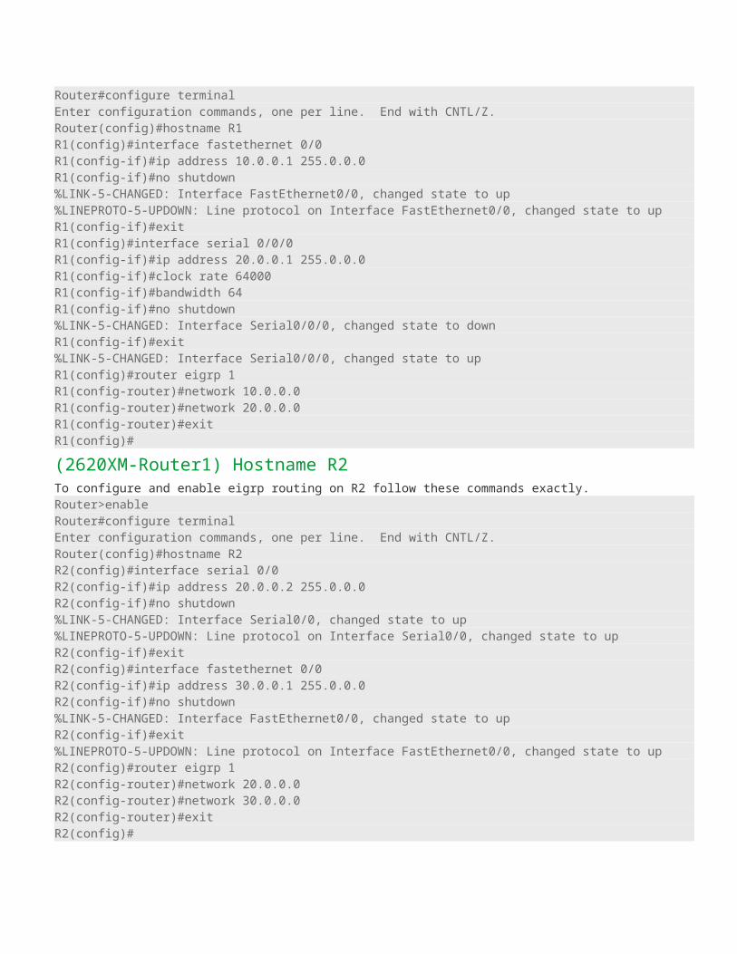
LSACK to the master to acknowledge the fact that it received the LSU. If a slave has more up-to-date information, it will repeat the "exchange" and "loading" states.4. Full stateOnce the master and the slave are synchronized, they are considered to be in a full state. To summarize these four steps, OSPF routers share a type of LSA message in order to disclose information about available routes. Basically, an LSA update message contains a link and a state, as well as other information.A link is the router interface on which the update was generated (a connected route).The state is a description of this interface, including the IP address configured on it as well as the relationship this router has with its neighboring router. However, OSPF routers will not share this information with just any OSPF router.A two-way state indicates that two OSPF routers are neighbors. A full state indicates the completion of sharing of links between routers.Cost metric is the inverse of the accumulated bandwidth values of routers’ interfaces. The default Measurement that Cisco uses in calculating the cost metric is: cost = 108/(interface bandwidth)
How to configure open shortest path first routing protocolIn this article I will demonstrate an example of OSPF Routing configuration. We will use four different series router so you can get familiar with all different platform covered in CCNA exam. Create a topology as shown in figure.
1841 Series Router0 (R1)FastEthernet0/0 Serial0/0/0
IP address 10.0.0.1 20.0.0.1
Connected With Pc0 R2 on Serial 0/0
2811 Series Router0 (R4)FastEthernet0/0 Serial0/0/0
IP address 50.0.0.1 40.0.0.2

Connected With Pc1 R3 on Serial 0/0
2621XM Series Router0 (R3)FastEthernet0/0 Serial0/0/0
IP address 30.0.0.2 40.0.0.1
Connected With FastEthernet0/0 R4 on Serial 0/0/0
2620XM Series Router1 (R2)FastEthernet0/0 Serial0/0
IP address 30.0.0.1 20.0.0.2
Connected With R3 on FastEthernet0/0 R1 on Serial 0/0/0
PC-PT PC0
FastEthernet0 Default Gateway
IP address 10.0.0.2 10.0.0.1
Connected With R1 on FastEthernet0/0
PC-PT PC1
FastEthernet0 Default Gateway
IP address 50.0.0.2 50.0.0.1
Connected With R4 on FastEthernet0/0
Configuring OSPF is slightly different from configuring RIP. When configuring OSPF, use the following syntax:Router(config)# router ospf process_IDRouter(config-router)# network IP_address wildcard_mask area area_#The process_ID is locally significant and is used to differentiate between OSPF processes running on the same router. Your router might be a boundary router between two OSPF autonomous systems, and to differentiate them on your router, you will give them unique process IDs. Note that these numbers do not need to match between different routers so they have nothing to do with autonomous system numbers.To configure any router double click on it and select CLI.To configure this topology use this step by step guide.
(1841Router0) Hostname R1To configure and enable ospf routing on R1 follow these commands exactly.Router>enableRouter#configure terminalEnter configuration commands, one per line. End with CNTL/Z.Router(config)#hostname R1R1(config)#interface fastethernet 0/0R1(config-if)#ip address 10.0.0.1 255.0.0.0R1(config-if)#no shutdown%LINK-5-CHANGED: Interface FastEthernet0/0, changed state to up%LINEPROTO-5-UPDOWN: Line protocol on Interface FastEthernet0/0, changed state to upR1(config-if)#exitR1(config)#interface serial 0/0/0

R1(config-if)#ip address 20.0.0.1 255.0.0.0R1(config-if)#clock rate 64000R1(config-if)#bandwidth 64R1(config-if)#no shutdown%LINK-5-CHANGED: Interface Serial0/0/0, changed state to downR1(config-if)#exit%LINK-5-CHANGED: Interface Serial0/0/0, changed state to upR1(config)#router ospf 1R1(config-router)#network 10.0.0.0 0.255.255.255 area 0R1(config-router)#network 20.0.0.0 0.255.255.255 area 0R1(config-router)#exitR1(config)#
(2620XM-Router1) Hostname R2To configure and enable ospf routing on R2 follow these commands exactly.Router>enableRouter#configure terminalEnter configuration commands, one per line. End with CNTL/Z.Router(config)#hostname R2R2(config)#interface serial 0/0R2(config-if)#ip address 20.0.0.2 255.0.0.0R2(config-if)#no shutdown%LINK-5-CHANGED: Interface Serial0/0, changed state to up%LINEPROTO-5-UPDOWN: Line protocol on Interface Serial0/0, changed state to upR2(config-if)#exitR2(config)#interface fastethernet 0/0R2(config-if)#ip address 30.0.0.1 255.0.0.0R2(config-if)#no shutdown%LINK-5-CHANGED: Interface FastEthernet0/0, changed state to upR2(config-if)#exit%LINEPROTO-5-UPDOWN: Line protocol on Interface FastEthernet0/0, changed state to upR2(config)#router ospf 2R2(config-router)#network 20.0.0.0 0.255.255.255 area 0R2(config-router)#network 300:03:10: %OSPF-5-ADJCHG: Process 2, Nbr 20.0.0.1 on Serial0/0 from LOADING to FULL, Loading Done0.0.0.0 0.255.255.255 area 0R2(config-router)#network 30.0.0.0 0.255.255.255 area 0R2(config-router)#exitR2(config)#
(2620XM-Router2)Hostname R3To configure and enable ospf routing on R3 follow these commands exactly.Router>enableRouter#configure terminalEnter configuration commands, one per line. End with CNTL/Z.Router(config)#hostname R3R3(config)#interface fastethernet 0/0R3(config-if)#ip address 30.0.0.2 255.0.0.0R3(config-if)#no shutdown%LINK-5-CHANGED: Interface FastEthernet0/0, changed state to up%LINEPROTO-5-UPDOWN: Line protocol on Interface FastEthernet0/0, changed state to upR3(config-if)#interface serial 0/0R3(config-if)#ip address 40.0.0.1 255.0.0.0R3(config-if)#clock rate 64000R3(config-if)#bandwidth 64R3(config-if)#no shutdown

%LINK-5-CHANGED: Interface Serial0/0, changed state to downR3(config-if)#exit%LINK-5-CHANGED: Interface Serial0/0, changed state to up%LINEPROTO-5-UPDOWN: Line protocol on Interface Serial0/0, changed state to upR3(config)#router ospf 3R3(config-router)#network 40.0.0.0 0.255.255.255 area 0R3(config-router)#network 30.0.0.0 0.255.255.255 area 000:04:53: %OSPF-5-ADJCHG: Process 3, Nbr 30.0.0.1 on FastEthernet0/0 from LOADING to FULL, Loading DR3(config-router)#exitR3(config)#%SYS-5-CONFIG_I: Configured from console by consoleR3#
(2811Router3) Hostname R4To configure and enable ospf routing on R4 follow these commands exactly.Router>enableRouter#configure terminalEnter configuration commands, one per line. End with CNTL/Z.Router(config)#interface serial 0/0/0Router(config-if)#ip address 40.0.0.2 255.0.0.0Router(config-if)#no shutdown%LINK-5-CHANGED: Interface Serial0/0/0, changed state to up%LINEPROTO-5-UPDOWN: Line protocol on Interface Serial0/0/0, changed state to upRouter(config-if)#exitRouter(config)#interface fastethernet 0/0Router(config-if)#ip address 50.0.0.1 255.0.0.0Router(config-if)#no shutdown%LINK-5-CHANGED: Interface FastEthernet0/0, changed state to up%LINEPROTO-5-UPDOWN: Line protocol on Interface FastEthernet0/0, changed state to upRouter(config-if)#exitR4(config)#router ospf 4R4(config-router)#network 50.0.0.0 0.255.255.255 area 0R4(config-router)#network 40.0.0.0 0.255.255.255 area 0R4(config-router)#00:06:32: %OSPF-5-ADJCHG: Process 4, Nbr 40.0.0.1 on Serial0/0/0 fromLOADING to FULL, Loading DoneR4(config-router)#exitR4(config)#
PC-1PC>ipconfig
IP Address......................: 10.0.0.2Subnet Mask.....................: 255.0.0.0Default Gateway.................: 10.0.0.1
PC>ping 50.0.0.2
Pinging 50.0.0.2 with 32 bytes of data:
Reply from 50.0.0.2: bytes=32 time=156ms TTL=124Reply from 50.0.0.2: bytes=32 time=127ms TTL=124

Reply from 50.0.0.2: bytes=32 time=156ms TTL=124Reply from 50.0.0.2: bytes=32 time=140ms TTL=124
Ping statistics for 50.0.0.2: Packets: Sent = 4, Received = 4, Lost = 0 (0% loss),Approximate round trip times in milli-seconds: Minimum = 127ms, Maximum = 156ms, Average = 144msPC>
PC-2PC>ipconfig
IP Address......................: 50.0.0.2Subnet Mask.....................: 255.0.0.0Default Gateway.................: 50.0.0.1
PC>ping 10.0.0.2
Pinging 10.0.0.2 with 32 bytes of data:
Reply from 10.0.0.2: bytes=32 time=140ms TTL=124Reply from 10.0.0.2: bytes=32 time=141ms TTL=124Reply from 10.0.0.2: bytes=32 time=157ms TTL=124Reply from 10.0.0.2: bytes=32 time=156ms TTL=124
Ping statistics for 10.0.0.2: Packets: Sent = 4, Received = 4, Lost = 0 (0% loss),Approximate round trip times in milli-seconds: Minimum = 140ms, Maximum = 157ms, Average = 148msYou can verify that ospf is running successfully via show ip protocols command in privilege mode.R4#show ip protocols
Routing Protocol is "ospf 4" Outgoing update filter list for all interfaces is not set Incoming update filter list for all interfaces is not set Router ID 50.0.0.1 Number of areas in this router is 1. 1 normal 0 stub 0 nssa Maximum path: 4 Routing for Networks: 50.0.0.0 0.255.255.255 area 0 40.0.0.0 0.255.255.255 area 0 Routing Information Sources: Gateway Distance Last Update 40.0.0.1 110 00:01:26 Distance: (default is 110)
R4#You can use show ip oute command to troubleshoot ospf network. If you did not see information about any route checks the router attached with that network.R4#show ip routeCodes: C - connected, S - static, I - IGRP, R - RIP, M - mobile, B - BGP D - EIGRP, EX - EIGRP external, O - OSPF, IA - OSPF inter area N1 - OSPF NSSA external type 1, N2 - OSPF NSSA external type 2 E1 - OSPF external type 1, E2 - OSPF external type 2, E - EGP i - IS-IS, L1 - IS-IS level-1, L2 - IS-IS level-2, ia - IS-IS inter area * - candidate default, U - per-user static route, o - ODR

P - periodic downloaded static route
Gateway of last resort is not set
O 10.0.0.0/8 [110/1564] via 40.0.0.1, 00:02:37, Serial0/0/0O 20.0.0.0/8 [110/1563] via 40.0.0.1, 00:02:37, Serial0/0/0O 30.0.0.0/8 [110/782] via 40.0.0.1, 00:02:37, Serial0/0/0C 40.0.0.0/8 is directly connected, Serial0/0/0C 50.0.0.0/8 is directly connected, FastEthernet0/0R4#To test ospf routing do ping from pc1 to pc2 and vice versa. If you get replay then you have successfully configured ospf routing but if you did not get replay double check this configuration and try to troubleshoot. I have uploaded a configured and tested topology in case you are unable to locate the problem spot then download this configuration file. And try to find out where have you committed mistakeospf routing configurations
Configuration command of OSPF
Commands Descriptions
Router(config)#router ospf 1Starts OSPF process 1. The process ID is any positive integer value between 1
and 65,535.
Router(config-router)#network
172.16.0.0 0.0.255.255 area 0
OSPF advertises interfaces, not networks. Uses the wildcard mask to determine
which interfaces to advertise.
Router(config-if)#ip ospf
hellointerval timer 20Changes the Hello Interval timer to 20 seconds.
Router(config-if)#ip ospf
deadinterval 80Changes the Dead Interval timer to 80 seconds.
NOTE: Hello and Dead Interval timers must match for routers to become neighbors
Router#show ip protocol Displays parameters for all protocols running on the router
Router#show ip route Displays a complete IP routing table
Router#show ip ospf Displays basic information about OSPF routing processes
Router#show ip ospf interface Displays OSPF info as it relates to all interfaces
Router#show ip ospf interface
fastethernet 0/0Displays OSPF information for interface fastethernet 0/0
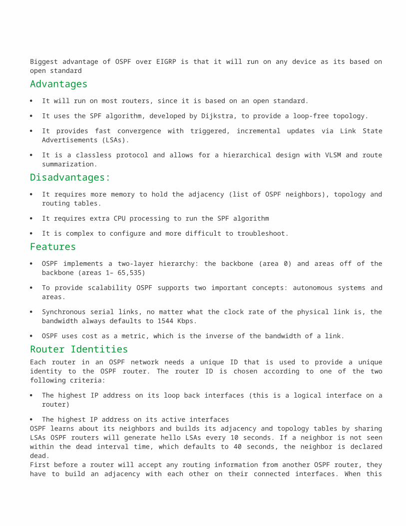
Router#show ip ospf border-
routersDisplays border and boundary router information
Router#show ip ospf neighbor Lists all OSPF neighbors and their states
Router#show ip ospf neighbor
detailDisplays a detailed list of neighbors
Router#clear ip route * Clears entire routing table, forcing it to rebuild
Router#clear ip route a.b.c.d Clears specific route to network a.b.c.d
Router#clear ip opsf counters Resets OSPF counters
Router#clear ip ospf processResets entire OSPF process, forcing OSPF to re-create neighbors, database, and
routing table
Router#debug ip ospf events Displays all OSPF events
Router#debug ip ospf adjacency Displays various OSPF states and DR/ BDR election between adjacent routers
Router#debug ip ospf packets Displays OPSF packets
How to configure EIGRP with RIP on same networkIn this article we will discuss how can two routing protocols exist in same network? We have discussed basic of both EIGRP and RIP in our previous article. Now we will go in more depth by including both RIP and EIGRP in same network.
ScenarioYou are the administrator at computernetworkingnotes.com. Company network is given below

R0Port IP address Connected toF0/0 80.0.0.1 R1 F0/1F1/0 90.0.0.1 R2 F0/1F1/1 100.0.0.1 R3 F0/1
R1Port IP address Connected toF0/0.10 10.0.0.1 S1 F0/24F0/0.20 20.0.0.1 S1 F0/24F0/1 80.0.0.2 R0 F0/0S0/0/0 30.0.0.1 R2 S0/0
R2Port IP address Connected toF0/1 90.0.0.2 R0 F1/0S0/0 30.0.0.2 R1 S0/0/0F0/0 40.0.0.1 WR1 0/1S0/1 50.0.0.1 R3 S0/0/1R3Port IP address Connected toF0/1 100.0.0.2 R0 F1/1S0/0/1 50.0.0.2 R2 S0/1F0/0.60 60.0.0.1 S1 G0/1

F0/0.70 70.0.0.1 S1 G0/1IP address and other necessary configurations are already done on routers, switches, and on pc's, you need only to configure routing.Company has 3 main routers R1, R2, R3 connected via serial cable. All these routers are also connected with R0 for backup. Your task is to configure routing protocols on these routers. Backup route should only use when main route is down. IP address and other necessary configuration is already done on all devices. You are only required to configure routing protocols on routers.Download pre configured topology form here and load it in packet tracerAdvance example of routing EIGRP with RIPIn this scenario R0 is only providing backup to main links of R1, R2, R3. And it should only use in the failure of main links. This is a tricky question. Its directly related to administrative distance. As we know Administrative distance of RIP is 120 and EIGRP is 90. If both protocol exist on same router and have path for destination, EIGRP path will be chosen by default as it have low AD value. And in routing decision low AD value is winner.
Configuration of R0First we will configure R0. To configure double click on R0 select CLI and configure it as given belowTo configure and enable RIP as backup routing on R0 follow these commands exactly.R0>enableR0#sh ip interface briefInterface IP-Address OK? Method Status Protocol
FastEthernet0/0 80.0.0.1 YES manual up up
FastEthernet1/0 90.0.0.1 YES manual up up
FastEthernet1/1 100.0.0.1 YES manual up upR0#configure terminalEnter configuration commands, one per line. End with CNTL/Z.R0(config)#router ripR0(config-router)#network 80.0.0.0R0(config-router)#network 90.0.0.0R0(config-router)#network 100.0.0.0R0(config-router)#exitR0(config)#exit%SYS-5-CONFIG_I: Configured from console by consoleR0#copy run startDestination filename [startup-config]?Building configuration...[OK]R0#We need not to configure EIGRP on it as its only going to be a backup route
Configuration of R1Now configure R1. On R1 we need to configure both RIP and EIGRP. RIP for backup and EIGRP for main route.R1>enableR1#show ip interface briefInterface IP-Address OK? Method Status Protocol
FastEthernet0/0 unassigned YES manual up up
FastEthernet0/0.10 10.0.0.1 YES manual up up
FastEthernet0/0.20 20.0.0.1 YES manual up up

FastEthernet0/1 80.0.0.2 YES manual up up
Serial0/0/0 30.0.0.1 YES manual up up
Serial0/0/1 unassigned YES manual administratively down down
Vlan1 unassigned YES manual administratively down downR1#configure terminalEnter configuration commands, one per line. End with CNTL/Z.R1(config)#router ripR1(config-router)#network 10.0.0.0R1(config-router)#network 20.0.0.0R1(config-router)#network 30.0.0.0R1(config-router)#network 80.0.0.0R1(config-router)#exitR1(config)#router eigrp 1R1(config-router)#network 10.0.0.0R1(config-router)#network 20.0.0.0R1(config-router)#network 30.0.0.0R1(config-router)#exitR1(config)#exit%SYS-5-CONFIG_I: Configured from console by consoleR1#copy run startDestination filename [startup-config]?Building configuration...[OK]R1#Why did we not include network 80.0.0.0 in EIGRP routing?Network 80.0.0.0 is connecting R1 to R0 which is backup route. And only going to be used In the failure of main EIGRP route.If we include network 80.0.0.0 in EIGRP routing, still R1 will take main EIGRP (via R2) route to reach R3 why?Because by default Matrix of EIGRP is bandwidth and delay, and in this scenario backup route (R1 – R0 – R3) is using Ethernet cable link and main EIGRP route ( R1 – R2 – R3) is using serial cable link. Serial link have better matrix then Ethernet link that's why R1 will take main EIGRP route to reach R3.
Configuration of R2To configure and enable eigrp with rip routing on R2 follow these commands exactly.Router>enableR2#show ip interface briefInterface IP-Address OK? Method Status Protocol
FastEthernet0/0 40.0.0.1 YES manual up up
FastEthernet0/1 90.0.0.2 YES manual up up
Serial0/0 30.0.0.2 YES manual up up
Serial0/1 50.0.0.1 YES manual up upR2#configure terminalEnter configuration commands, one per line. End with CNTL/Z.R2(config)#router ripR2(config-router)#network 30.0.0.0R2(config-router)#network 40.0.0.0R2(config-router)#network 50.0.0.0

R2(config-router)#network 90.0.0.0R2(config-router)#exitR2(config)#router eigrp 1R2(config-router)#network 30.0.0.0R2(config-router)#R2(config-router)#network 40.0.0.0R2(config-router)#network 50.0.0.0R2(config-router)#exitR2(config)#exit%SYS-5-CONFIG_I: Configured from console by consoleR2#
Configuration of R3To configure and enable eigrp with rip routing on R3 follow these commands exactly.Router>enableR3#show ip interface briefInterface IP-Address OK? Method Status Protocol
FastEthernet0/0 unassigned YES manual up up
FastEthernet0/0.60 60.0.0.1 YES manual up up
FastEthernet0/0.70 70.0.0.1 YES manual up up
FastEthernet0/1 100.0.0.2 YES manual up up
Serial0/0/0 unassigned YES manual administratively down down
Serial0/0/1 50.0.0.2 YES manual up up
Vlan1 unassigned YES manual administratively down downR3#configure terminalEnter configuration commands, one per line. End with CNTL/Z.R3(config)#router ripR3(config-router)#network 50.0.0.0R3(config-router)#network 60.0.0.0R3(config-router)#network 70.0.0.0R3(config-router)#network 100.0.0.0R3(config-router)#exitR3(config)#router eigrp 1R3(config-router)#network 50.0.0.0R3(config-router)#networkR3(config-router)#network 60.0.0.0R3(config-router)#network 70.0.0.0R3(config-router)#exitR3(config)#exit%SYS-5-CONFIG_I: Configured from console by consoleR3#
Testing of EIGRP with RIPNow we have configured both RIP and EIGRP in this network. To test this network double click on PC-PT PC0 and select command prompt tracert 70.0.0.3

As you can see image R1 is taking Main EIGRP route to rich at R3Now remove the serial cable by using red cross sign shown in right control panel
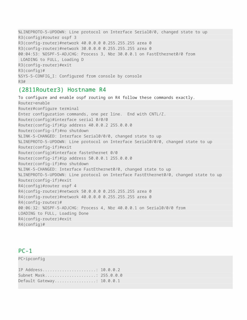
Now again tracert 70.0.0.3 from PC0
As you can see in image this time R1 takes R0 to reach R3 because Main EIGRP route is downWe have a configured topology here for cross checking if you have done any error in configuration. Download it and check where you have done mistakeAdvance example of routing EIGRP with RIP configured