rover assembly guide
TRANSCRIPT

User Guide Rover 6” Mecanum Drive (am-4100_MK6)
Variants: am-4100k_MK6
am-4100m_MK6 am-4100mk_MK6

2
Additional Instructions Available We encourage customers to seek product information at AndyMark.com. Contact us via e-mail at
[email protected], or call Toll-Free 877-868-4770 with questions about any of our products.
Update History: 10-17-19: Initial Release
12-27-19: Revised Electrical Layout
03-20-20: Updated BoM and relevant parts in various steps
Rover Chassis Recommended Hand Tool List (not included)
Component Part Number QTY Part Photo
1/8” Allen Driver am-2750 1
3/32” Allen Driver am-3173 1
5/32" Allen Driver am-2751 1
3mm Allen Driver am-3688 1
2.5mm Allen Driver am-3724 1
5.5mm Nut Driver am-1287 1
3/8 in Nut Driver am-3877 1
7mm Combination Wrench am-4140 1
3/8"-7/16" Open End Wrench am-2745 1
Retaining Ring Pliers am-4013 1
TRIcrimp PowerPle Crimper am-2554 1
Hand Rivet Tool am-2834 1
Ferrule Crimp Tool am-3739 1
¼ Inch Drill Bit am-4048 1

3
Gearbox Assembly Bill of Materials
Component Part Number QTY Part Photo
RedLine Motor with 16 Tooth Pinion Gear Installed
am-3775a_16t 4
57 Sport 3 Inch Shaft am-3791 4
57 Sport Gearbox, 64:1, SD am-3973_064 4
57 Sport Motor Block am-3765 4
57 Sport Flange Mount am-4132 4
10-32 x 0.5 Inch Button Head Cap Screw
am-1512 8
Red Tacky Grease, 14.2 gram am-2768 1
6” Mecanum Wheel Assembly Bill of Materials
Component Part Number QTY Part Photo
6” SR Mecanum wheel Set am-3479a 1
1/2 Inch Extruded Hex Hub am-2568 4
10-32 x 0.75 Inch Socket Head Cap Screw
am-1047 24
10-32 Nylock Jam Nut am-1063 24
Chassis Assembly Bill of Materials
Component Part Number QTY Part Photo
Rover Drive Rail am-4094 2
1/2 Inch Hex Bore Bearing, Flanged am-2986 4

4
1/2 Inch Hex Spacer x 1.0 Inch am-3948-1000 4
10-32 x 0.625 Inch Socket Head Cap Screw
am-1007 8
10-32 Nylock Jam Nut am-1063 8
Rover End Rail am-4131 2
1/4-20 x 1.75 Inch Self Tapping Screw
am-1372 24
0.375 in. OD x 0.257 in. ID x 0.875 in. Aluminum Spacer
am-1513 16
10-32 x 0.375 Inch Socket Head Cap Screw
am-1359 4
#10 x 0.75 Inch Fender Washer am-1523 4
Rover Chassis Bottom Plate, Polycarbonate
am-4100_bottom 1
3/16 Inch Rivet, 0.376-0.5 Inch Range
am-1340 8
Electronics Assembly Bill of Materials
Component Part Number QTY Part Photo
M3 x 14mm Socket Head Cap Screw am-1367 6
M3 Nylock Nut am-1023 6
S3 Corner Gusset am-3606 2
PowerPole Distribution Board am-3699 1
CAN connector am-4130 1
5
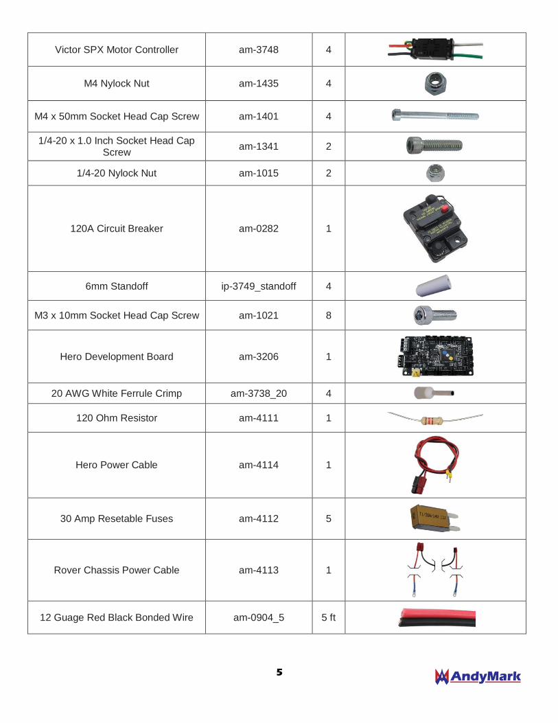
Victor SPX Motor Controller am-3748 4
M4 Nylock Nut am-1435 4
M4 x 50mm Socket Head Cap Screw am-1401 4
1/4-20 x 1.0 Inch Socket Head Cap Screw
am-1341 2
1/4-20 Nylock Nut am-1015 2
120A Circuit Breaker am-0282 1
6mm Standoff ip-3749_standoff 4
M3 x 10mm Socket Head Cap Screw am-1021 8
Hero Development Board am-3206 1
20 AWG White Ferrule Crimp am-3738_20 4
120 Ohm Resistor am-4111 1
Hero Power Cable am-4114 1
30 Amp Resetable Fuses am-4112 5
Rover Chassis Power Cable am-4113 1
12 Guage Red Black Bonded Wire am-0904_5 5 ft

6
Powerpole Kit, 8 Pack am-2198 2
Female Spade Connector, 12-10 AWG, Yellow, 10 Pack
am-2211 1
Rover Chassis Top Plate, Polycarbonate
am-4100_top 1
10-32 x 1.375 Inch Socket Head Cap Screw
am-1154 8
Nylon Spacer ¾ Inch Long am-4107 8
10-32 Nylock Jam Nut am-1063 10
AM14U Family Horizontal Battery Mount Strap Plate
am-2940 2
10-32 x 2.75 Inch Socket Head Cap Screw
am-1397 6
10-32 x 0.5 Inch Button Head Cap Screw
am-1512 2
10-32 Wing Nut am-1483 6
F710 Wireless Logitech Game Controller
am-4049 1

7
Gearbox Assembly Instructions (QTY 4)
Each Rover 6” Mecanum Chassis includes four (4) AndyMark 57 Sport Gearboxes in a 64:1 ratio (am-4006_064).
Four (4) AndyMark 775a RedLine Motors with 16t Pinions (am-3775a_16T) are also included along with the
hardware necessary to mount the motors to the gearboxes. Additionally, a 57 Sport 3 inch Shaft (am-3791) is
included for each gearbox to allow for the cantilevered wheel setup utilized in the Rover Chassis.
The 64:1 ratio has been chosen specifically for use with the 6 inch mecanum wheels to provide a fast and agile
platform to build upon. Other ratios or wheel sizes (sold separately) can be used with the Rover chassis to suit
your specific needs.
*Stall Torque and Free Speed are calculated using the unmodified specs of a pair of AndyMark 775a RedLine Motors
8
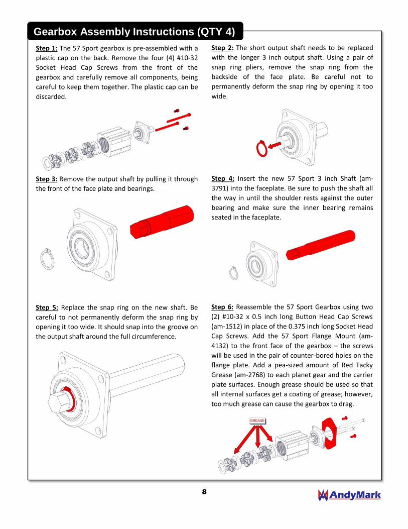
Step 1: The 57 Sport gearbox is pre-assembled with a
plastic cap on the back. Remove the four (4) #10-32
Socket Head Cap Screws from the front of the
gearbox and carefully remove all components, being
careful to keep them together. The plastic cap can be
discarded.
Step 2: The short output shaft needs to be replaced
with the longer 3 inch output shaft. Using a pair of
snap ring pliers, remove the snap ring from the
backside of the face plate. Be careful not to
permanently deform the snap ring by opening it too
wide.
Gearbox Assembly Instructions (QTY 4)
Step 3: Remove the output shaft by pulling it through
the front of the face plate and bearings.
Step 4: Insert the new 57 Sport 3 inch Shaft (am-
3791) into the faceplate. Be sure to push the shaft all
the way in until the shoulder rests against the outer
bearing and make sure the inner bearing remains
seated in the faceplate.
Step 5: Replace the snap ring on the new shaft. Be
careful to not permanently deform the snap ring by
opening it too wide. It should snap into the groove on
the output shaft around the full circumference.
Step 6: Reassemble the 57 Sport Gearbox using two
(2) #10-32 x 0.5 inch long Button Head Cap Screws
(am-1512) in place of the 0.375 inch long Socket Head
Cap Screws. Add the 57 Sport Flange Mount (am-
4132) to the front face of the gearbox – the screws
will be used in the pair of counter-bored holes on the
flange plate. Add a pea-sized amount of Red Tacky
Grease (am-2768) to each planet gear and the carrier
plate surfaces. Enough grease should be used so that
all internal surfaces get a coating of grease; however,
too much grease can cause the gearbox to drag.
9
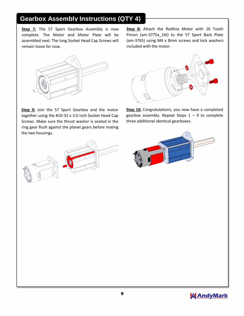
Step 7: The 57 Sport Gearbox Assembly is now
complete. The Motor and Motor Plate will be
assembled next. The long Socket Head Cap Screws will
remain loose for now.
Step 8: Attach the Redline Motor with 16 Tooth
Pinion (am-3775a_16t) to the 57 Sport Back Plate
(am-3765) using M4 x 8mm screws and lock washers
included with the motor.
Gearbox Assembly Instructions (QTY 4)
Step 9: Join the 57 Sport Gearbox and the motor
together using the #10-32 x 3.0 inch Socket Head Cap
Screws. Make sure the thrust washer is seated in the
ring gear flush against the planet gears before mating
the two housings.
Step 10: Congratulations, you now have a completed
gearbox assembly. Repeat Steps 1 – 9 to complete
three additional identical gearboxes.
10
Wheel Assembly Instructions (QTY 4)
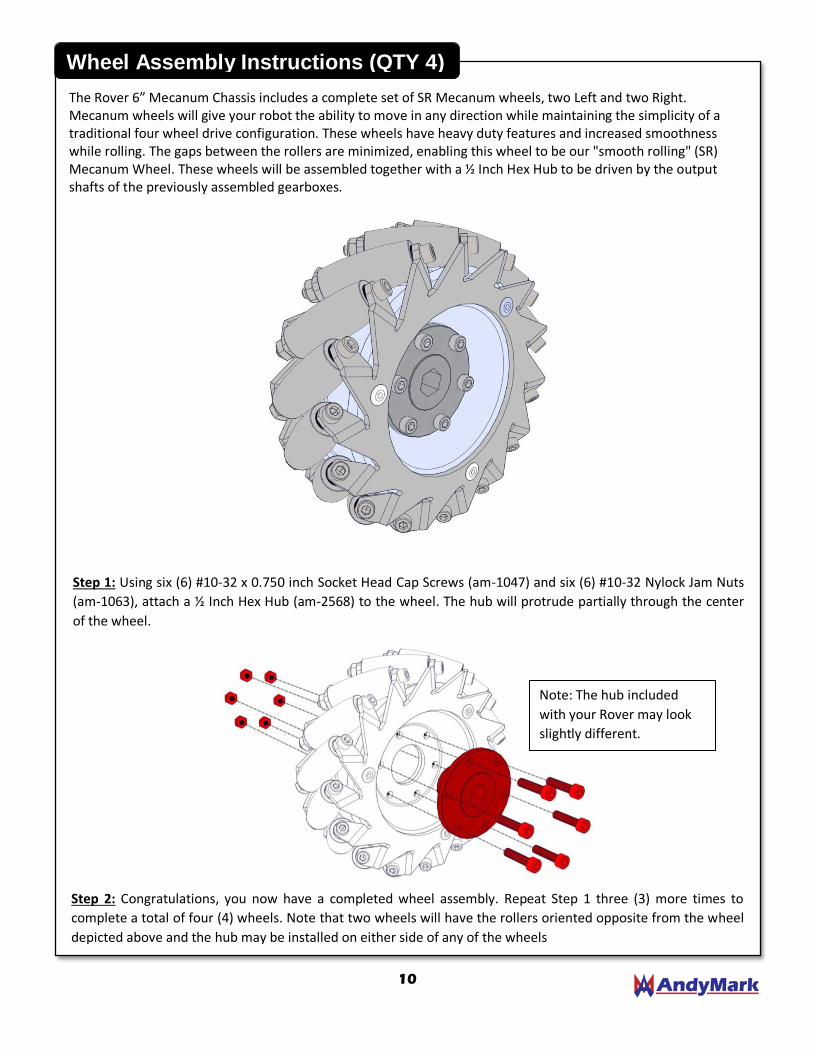
The Rover 6” Mecanum Chassis includes a complete set of SR Mecanum wheels, two Left and two Right. Mecanum wheels will give your robot the ability to move in any direction while maintaining the simplicity of a traditional four wheel drive configuration. These wheels have heavy duty features and increased smoothness while rolling. The gaps between the rollers are minimized, enabling this wheel to be our "smooth rolling" (SR) Mecanum Wheel. These wheels will be assembled together with a ½ Inch Hex Hub to be driven by the output shafts of the previously assembled gearboxes.
Step 1: Using six (6) #10-32 x 0.750 inch Socket Head Cap Screws (am-1047) and six (6) #10-32 Nylock Jam Nuts
(am-1063), attach a ½ Inch Hex Hub (am-2568) to the wheel. The hub will protrude partially through the center
of the wheel.
Step 2: Congratulations, you now have a completed wheel assembly. Repeat Step 1 three (3) more times to
complete a total of four (4) wheels. Note that two wheels will have the rollers oriented opposite from the wheel
depicted above and the hub may be installed on either side of any of the wheels
Note: The hub included
with your Rover may look
slightly different.
11
Chassis Assembly Instructions
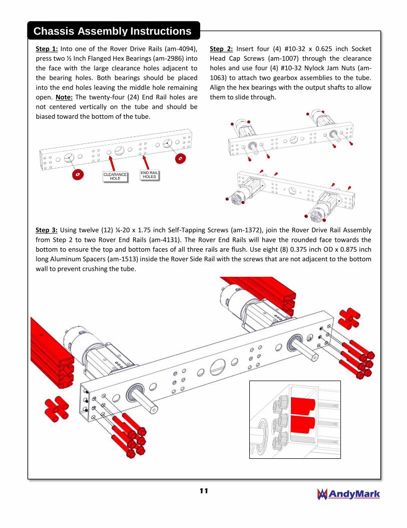
Step 1: Into one of the Rover Drive Rails (am-4094),
press two ½ Inch Flanged Hex Bearings (am-2986) into
the face with the large clearance holes adjacent to
the bearing holes. Both bearings should be placed
into the end holes leaving the middle hole remaining
open. Note: The twenty-four (24) End Rail holes are
not centered vertically on the tube and should be
biased toward the bottom of the tube.
Step 2: Insert four (4) #10-32 x 0.625 inch Socket
Head Cap Screws (am-1007) through the clearance
holes and use four (4) #10-32 Nylock Jam Nuts (am-
1063) to attach two gearbox assemblies to the tube.
Align the hex bearings with the output shafts to allow
them to slide through.
Step 3: Using twelve (12) ¼-20 x 1.75 inch Self-Tapping Screws (am-1372), join the Rover Drive Rail Assembly
from Step 2 to two Rover End Rails (am-4131). The Rover End Rails will have the rounded face towards the
bottom to ensure the top and bottom faces of all three rails are flush. Use eight (8) 0.375 inch OD x 0.875 inch
long Aluminum Spacers (am-1513) inside the Rover Side Rail with the screws that are not adjacent to the bottom
wall to prevent crushing the tube.
12
Chassis Assembly Instructions
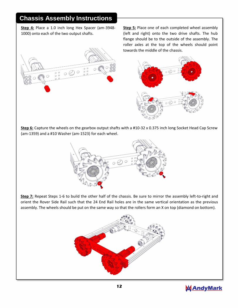
Step 4: Place a 1.0 inch long Hex Spacer (am-3948-
1000) onto each of the two output shafts.
Step 5: Place one of each completed wheel assembly
(left and right) onto the two drive shafts. The hub
flange should be to the outside of the assembly. The
roller axles at the top of the wheels should point
towards the middle of the chassis.
Step 6: Capture the wheels on the gearbox output shafts with a #10-32 x 0.375 inch long Socket Head Cap Screw
(am-1359) and a #10 Washer (am-1523) for each wheel.
Step 7: Repeat Steps 1-6 to build the other half of the chassis. Be sure to mirror the assembly left-to-right and
orient the Rover Side Rail such that the 24 End Rail holes are in the same vertical orientation as the previous
assembly. The wheels should be put on the same way so that the rollers form an X on top (diamond on bottom).
13
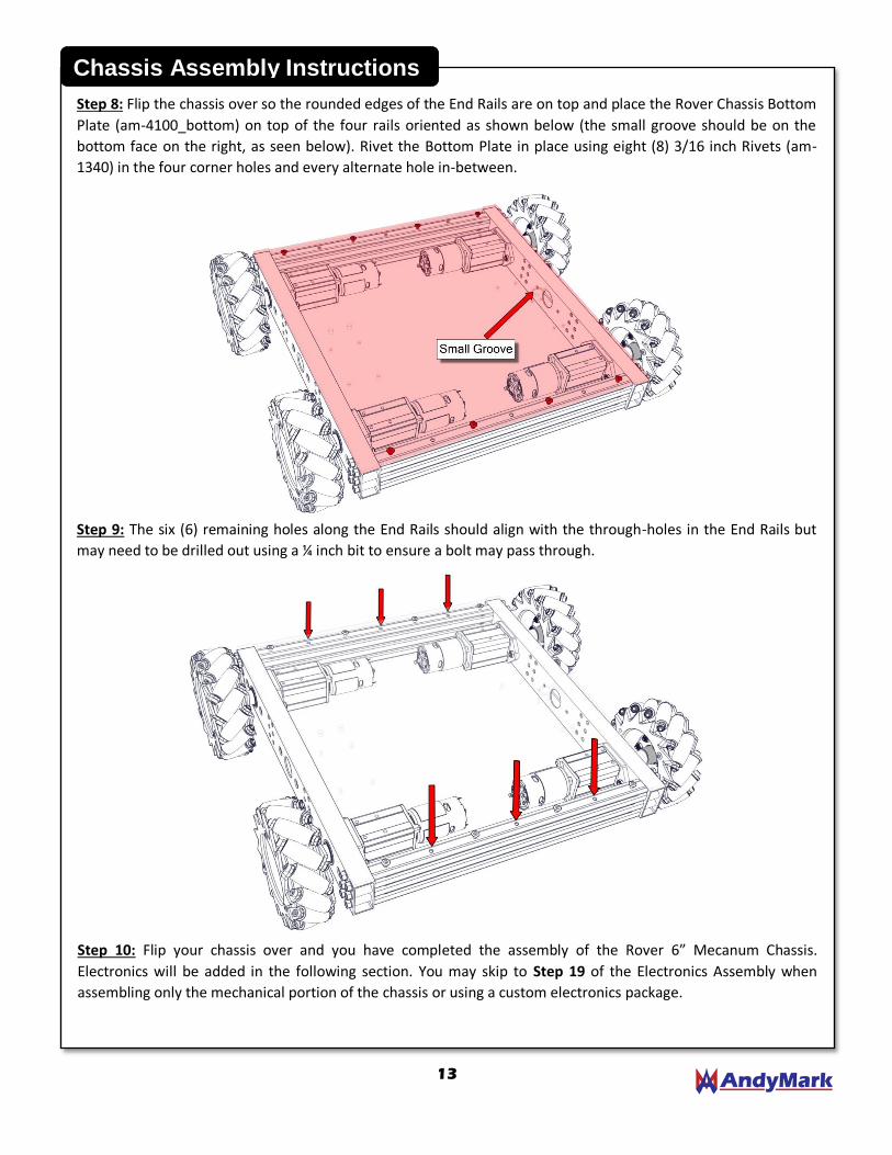
Step 8: Flip the chassis over so the rounded edges of the End Rails are on top and place the Rover Chassis Bottom
Plate (am-4100_bottom) on top of the four rails oriented as shown below (the small groove should be on the
bottom face on the right, as seen below). Rivet the Bottom Plate in place using eight (8) 3/16 inch Rivets (am-
1340) in the four corner holes and every alternate hole in-between.
Step 9: The six (6) remaining holes along the End Rails should align with the through-holes in the End Rails but
may need to be drilled out using a ¼ inch bit to ensure a bolt may pass through.
Step 10: Flip your chassis over and you have completed the assembly of the Rover 6” Mecanum Chassis.
Electronics will be added in the following section. You may skip to Step 19 of the Electronics Assembly when
assembling only the mechanical portion of the chassis or using a custom electronics package.
Chassis Assembly Instructions
14
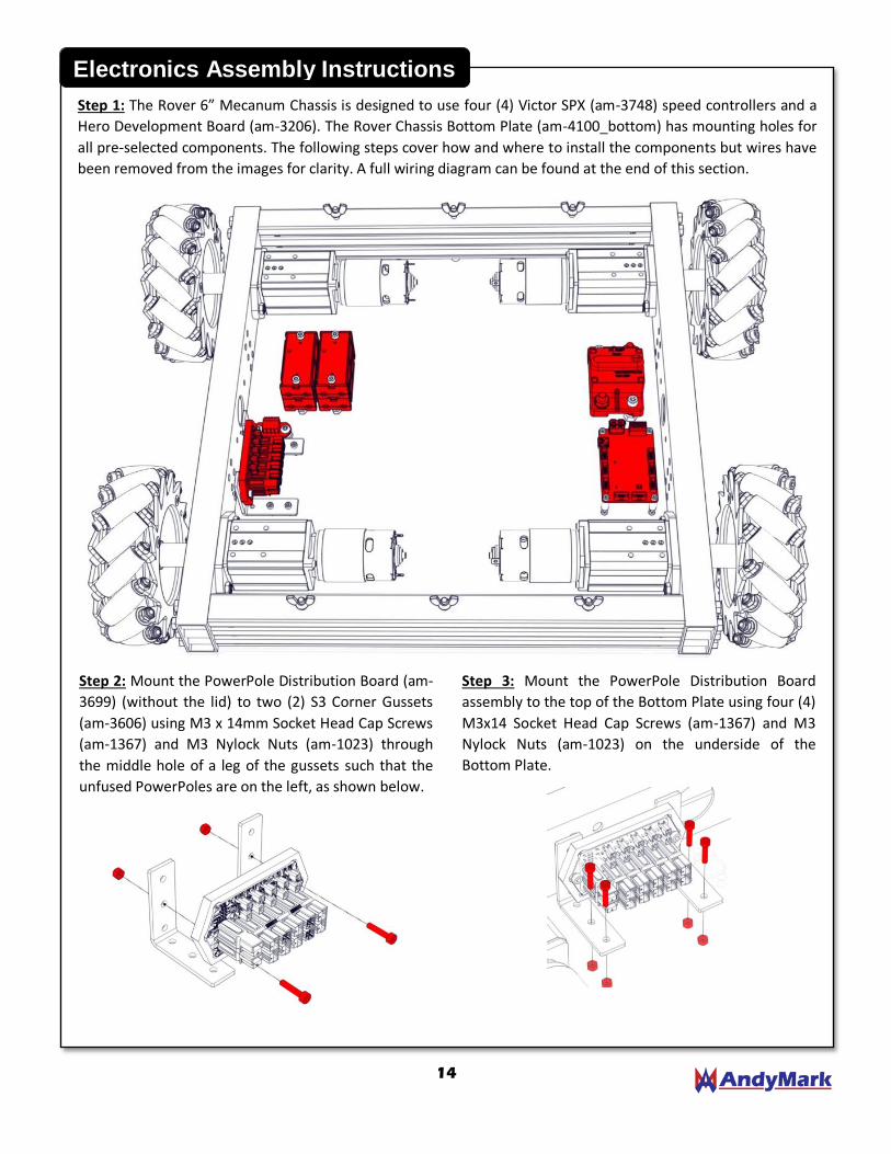
Step 1: The Rover 6” Mecanum Chassis is designed to use four (4) Victor SPX (am-3748) speed controllers and a
Hero Development Board (am-3206). The Rover Chassis Bottom Plate (am-4100_bottom) has mounting holes for
all pre-selected components. The following steps cover how and where to install the components but wires have
been removed from the images for clarity. A full wiring diagram can be found at the end of this section.
Electronics Assembly Instructions
Step 2: Mount the PowerPole Distribution Board (am-
3699) (without the lid) to two (2) S3 Corner Gussets
(am-3606) using M3 x 14mm Socket Head Cap Screws
(am-1367) and M3 Nylock Nuts (am-1023) through
the middle hole of a leg of the gussets such that the
unfused PowerPoles are on the left, as shown below.
Step 3: Mount the PowerPole Distribution Board
assembly to the top of the Bottom Plate using four (4)
M3x14 Socket Head Cap Screws (am-1367) and M3
Nylock Nuts (am-1023) on the underside of the
Bottom Plate.

15
Electronics Assembly Instructions
Step 4: Attach the CAN Connector (am-4130) to the
Bottom Plate using two (2) #10-32 x 0.5 long inch
Button Head Cap Screws (am-1512) and #10-32
Nylock Jam Nuts (am-1063) on the underside of the
Bottom Plate. Be sure to orient the CAN Connector
such that the wire terminals face away from the
PowerPole Distribution Board.
Step 5: Add PowerPoles (am-2198) to the four power
leads on each Victor SPX. Red PowerPoles should be
added to the Red and White leads and black
PowerPoles should be added to the Black and Green
leads. A PowerPole Crimp Tool (am-2554) (sold
separately) should be used to ensure a proper crimp.
Step 6: Add four (4) Victor SPX Speed Controllers (am-
3748) in two stacks of two with the CAN wires
oriented facing towards the CAN Connector. Use four
(4) M4x50 Socket Head Cap Screws (am-1401) and M4
Nylock Nuts (am-1435) to secure the controllers to
the top of the Bottom Plate.
Step 7: Cut one pair of CAN (yellow and green) wires
on one of the bottom Victors to approximately 3
inches long. Save the cut off wire for use in Step 9.
Strip the ends of the remaining wires and crimp 20
AWG White Ferrules (am-3738_20) onto each wire.
Insert the yellow wire into the CAN Connector in one
of the “HI” terminals and the green wire into one of
the “LO” terminals. Insert the legs of the CAN Resistor
(am-4111) into the remaining “HI” and “LO”
terminals.
Step 8: Connect the remaining CAN wires together
leaving one pair (from any Victor) open. Secure the
connections with the provided retainer clips
Step 9: Connect the cut off wire from Step 7 to the
remaining open pair of wires from Step 8. Strip the
cut ends of the pair of wires and crimp 20 AWG White
Ferrules (am-3738_20) onto each wire.

16
Step 10: Attach the 120A Circuit Breaker (am-0282)
on the other side of the robot from the previous
components using two (2) ¼-20 x 1.0 inch long Socket
Head Cap Screws (am-1341) and ¼-20 Nylock Nuts
(am-1015) on the underside of the Bottom Plate.
Step 11: Press the smaller end of four (4) 6mm
Standoffs (am-3749_standoff) into the top side of the
Bottom Plate and secure from underneath with four
(4) M3 x 10mm Socket Head Cap Screws (am-1021).
Electronics Assembly Instructions
Step 12: Place the Hero Development Board (am-
3206) on top of the standoffs with the USB port
towards the motors. Secure the Hero using four (4)
M3 x 10mm Socket Head Cap Screws (am-1021).
Step 13: Plug the CAN wires prepped in Step 9 into
the Hero Development Board. The connector is
labeled for the green and yellow wires.
Step 14: Insert the ends of the Hero Power Cable (am-
4114) with ferrules into the connector on the Hero
Board. Route this cable along the motors and past the
Victors and plug the PowerPoles into the PowerPole
Distribution Board closest to the Victors.
Step 15: Plug the red and black wires from the Victors
into the adjacent four sets of PowerPoles on the
PowerPole Distribution Board.
Step 16: Plug the Rover Chassis Power Cable (am-
4113) into the PowerPole Distribution Board at the
terminals furthest away from the motors. The ring
terminals will connect to the 120A Circuit Breaker.
17
Electronics Assembly Instructions
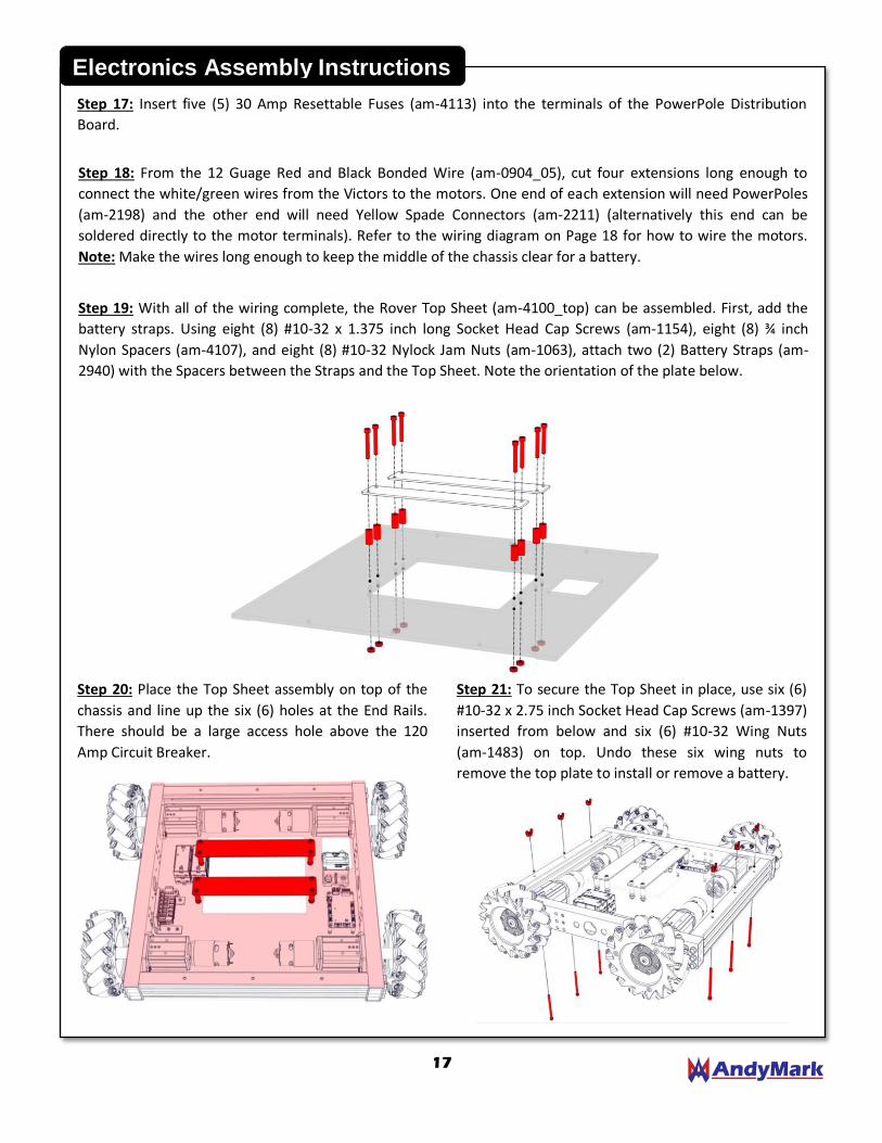
Step 17: Insert five (5) 30 Amp Resettable Fuses (am-4113) into the terminals of the PowerPole Distribution
Board.
Step 18: From the 12 Guage Red and Black Bonded Wire (am-0904_05), cut four extensions long enough to
connect the white/green wires from the Victors to the motors. One end of each extension will need PowerPoles
(am-2198) and the other end will need Yellow Spade Connectors (am-2211) (alternatively this end can be
soldered directly to the motor terminals). Refer to the wiring diagram on Page 18 for how to wire the motors.
Note: Make the wires long enough to keep the middle of the chassis clear for a battery.
Step 19: With all of the wiring complete, the Rover Top Sheet (am-4100_top) can be assembled. First, add the
battery straps. Using eight (8) #10-32 x 1.375 inch long Socket Head Cap Screws (am-1154), eight (8) ¾ inch
Nylon Spacers (am-4107), and eight (8) #10-32 Nylock Jam Nuts (am-1063), attach two (2) Battery Straps (am-
2940) with the Spacers between the Straps and the Top Sheet. Note the orientation of the plate below.
Step 20: Place the Top Sheet assembly on top of the
chassis and line up the six (6) holes at the End Rails.
There should be a large access hole above the 120
Amp Circuit Breaker.
Step 21: To secure the Top Sheet in place, use six (6)
#10-32 x 2.75 inch Socket Head Cap Screws (am-1397)
inserted from below and six (6) #10-32 Wing Nuts
(am-1483) on top. Undo these six wing nuts to
remove the top plate to install or remove a battery.

18
Wiring Diagram
The following schematic shows where each wire should be connected and generally how the wires should be laid
out in the Rover Chassis.
+ -
120A BREAKER
CAN
CONNECTOR BO
TTO
M
VIC
TOR
BO
TTO
M
VIC
TOR
TOP
VIC
TOR
TOP
VIC
TOR
HER
O
DEV
ELO
PM
ENT
BO
AR
D
TO BATTERY
PO
WER
PO
LE
DIS
TRIB
UTI
ON
BO
AR
D
RedLine Motor: The back of the RedLine motor has a
positive and negative terminal. The positive terminal
is in the black plastic housing with a notch:
NOTCH
Programming: The default source code for the Rover
6” Mecanum Chassis can be found at
https://github.com/AndyMark/RoverMecanumDrive.
+
-
+
-
+
-