royal government of cambodia - mpwt.gov.kh. mission report of... · royal government of cambodia...
TRANSCRIPT

Royal Government of Cambodia
Ministry of Public Works and Transport
ADB LOAN(SF) 2373-CAM
GREATER MEKONG SUBREGION SOUTHERN COASTAL CORRIDOR PROJECT
Construction and Maintenance Supervision
Mission Report of Material for NR33 and NR3 October 2011
Version A
In Association with Khmer Associates Consultant Engineers Co. Ltd. Key Consultants Cambodia, Khmer Consultant Engineering Corporation Ltd. SBK Research and Development, and VIDO Engineering Consultant Co. Ltd.
ADB/GMS‐SCCP CW1&CW2 Mission Report of Material for NR33 and NR3 Egis International
2 | P a g e
GMS Southern Coastal Corridor Project
P. Cario – Report Mission 3‐16/10/2011
Contents1. Purpose of the Mission ...............................................................................................................................3
2. Mission Findings ..........................................................................................................................................3
2.1 Unsuitable materials of existing subgrade ................................................................................................3
2.1.1 Tests Pits of existing subgrade of NR 33 ............................................................................................5
2.1.2 Tests analysis results ..........................................................................................................................5
2.1.3 Site Photos of Investigation Pits ........................................................................................................5
2.2 Subgrade, sub‐base, base course and crushed aggregates for DBST for NR33 ........................................6
2.2.1 Lateritic borrow area “THKOW Mountain” ........................................................................................6
2.2.2 Stone quarry / crushing plant ............................................................................................................6
2.3 Provision of Laboratory Equipment for NR33 ...........................................................................................7
2.4 Materials for NR3 and stability of verge/margin of NR3 ..........................................................................8
3. Conclusion ................................................................................................................................................ 10
Attachment 1 – AASHTO M145‐91
Attachment 2 ‐ Laboratory Test Results of Existing Subgrade Materials of NR33
Attachment 3 ‐ Site Photos of Investigation Pits
Attachment 4 ‐ FICHE GITE MATERIAUX
Attachment 5 – Proposed list of Laboratory Equipment from Contractor
Attachment 6 – Laboratory Equipment for SCCP – CW1 Contract
Attachment 7 – Photos of the borrow pit and quarry of materials for NR3
Attachment 8 ‐ Laboratory Test Results of Sample No. S035


ADB/GMS‐SCCP CW1&CW2 Mission Report of Material for NR33 and NR3 Egis International
5 | P a g e
2.1.1TestsPitsofexistingsubgradeofNR33
Pit No 1 Pk/km 2.660 R.S ~ 2m of flooded paddy field 0.00 – 0.20 Fine gray sand to very fine Sand, red and yellow color Sample A 0.20 – 0.45 Id. more wet Sample B 0.45 – 1.60 Id. with small layers of clayed sand/sandy clay.
Pit No 2 Pk/km 7.80 L.S 0.00 – 0.25 Sand and Clayed Sand yellow – red Sample A 0.25 – 0.60 Fine sand, no cohesion because it is very wet Sample B 0.60 – 1.70 Id. with more clay
Water penetration at 0.60 deep – Sand slide/fall into the pit
Pit No 3 Pk/km 10.770 R.S 0.00 – 0.25 Lateritic materials Sample A 0.25 – 0.60 Sand fine gray light clayed Sample B 0.60 – 1.60 Sandy clay with yellow and red color
2.1.2Testsanalysisresults
Pit no Sample LL PI MDD + OMC (%)
CBR (%)
Pit no 1 A 2.2.2 9.06 2.052 g/cc 7.30
2.80
B 27.20 16.04 2.029 g/cc 10.30
2.00
Pit no 2 A No Plastic 1.775 g/cc 7.90
12.05
B No Plastic 1.995 g/cc 9.80
18.0
Pit no 3 A No Plastic 1.989 g/cc 8.60
21.0
B 36.7 23.51 1.975 g/cc 8.50
0.80
(See Attachment 2 ‐ Laboratory Test Results of Existing Subgrade Materials of NR33)
All materials are not unsuitable according to AASHTO Standard.
Only Sample B of pit No 3 has bad results of CBR (less than 1), but this bad or unsuitable material is ~1m
below the good materials of CBR – 21.0, so it shouldn’t be removed.
2.1.3SitePhotosofInvestigationPits(See Attachment 3 ‐ Site Photos of Investigation Pits)
ADB/GMS‐SCCP CW1&CW2 Mission Report of Material for NR33 and NR3 Egis International
6 | P a g e
2.2Subgrade,sub‐base,basecourseandcrushedaggregatesforDBSTforNR33
2.2.1Lateriticborrowarea“THKOWMountain”Investigation results of the lateritic borrow area are given in the attached page “Attachment 4 ‐ FICHE GITE
MATERIAUX”.
Based on the test result from laboratory and visual inspection, Materials from “THKOW Mountain” are good
for subgrade and correct for sub‐base. Engineer should carry out frequent visit/select the material
extraction areas, taking samples and send to laboratory for testing as per Sampling and Testing Frequency
specified in the Technical Specification. Trial section for compaction is necessary to determine a good
moisture content W%, number of passes for compaction required.
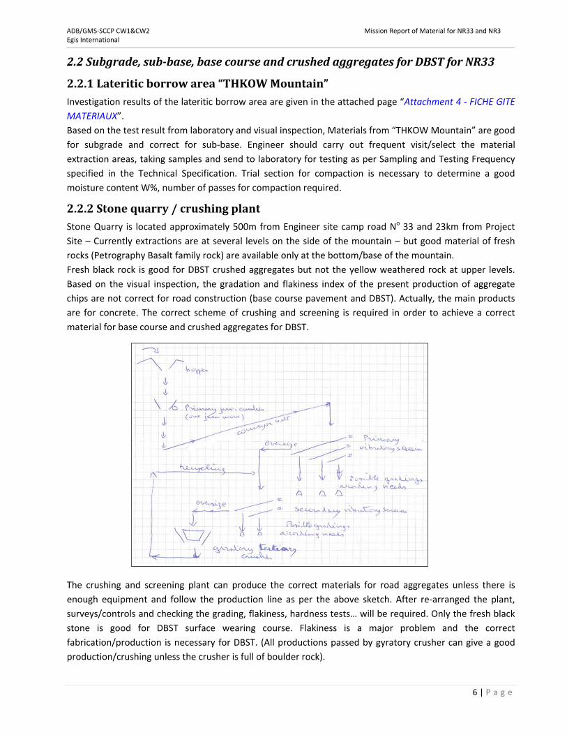
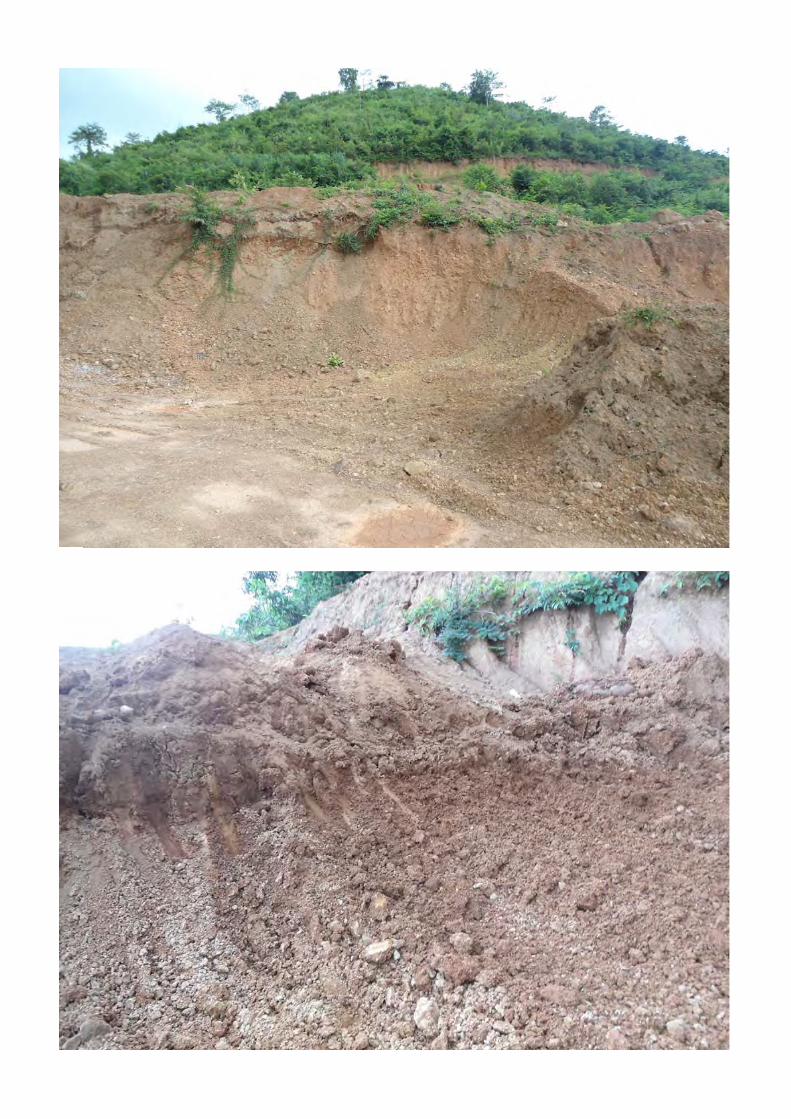
2.2.2Stonequarry/crushingplantStone Quarry is located approximately 500m from Engineer site camp road No 33 and 23km from Project
Site – Currently extractions are at several levels on the side of the mountain – but good material of fresh
rocks (Petrography Basalt family rock) are available only at the bottom/base of the mountain.
Fresh black rock is good for DBST crushed aggregates but not the yellow weathered rock at upper levels.
Based on the visual inspection, the gradation and flakiness index of the present production of aggregate
chips are not correct for road construction (base course pavement and DBST). Actually, the main products
are for concrete. The correct scheme of crushing and screening is required in order to achieve a correct
material for base course and crushed aggregates for DBST.
The crushing and screening plant can produce the correct materials for road aggregates unless there is
enough equipment and follow the production line as per the above sketch. After re‐arranged the plant,
surveys/controls and checking the grading, flakiness, hardness tests… will be required. Only the fresh black
stone is good for DBST surface wearing course. Flakiness is a major problem and the correct
fabrication/production is necessary for DBST. (All productions passed by gyratory crusher can give a good
production/crushing unless the crusher is full of boulder rock).

ADB/GMS‐SCCP CW1&CW2 Mission Report of Material for NR33 and NR3 Egis International
7 | P a g e
2.3ProvisionofLaboratoryEquipmentforNR33The proposed list of the Contractor through Sakor Combodia Co Ltd is not complete, many equipment
items are missing, and they are very important for proper execution of test:
‐ Weighing scale 3.5 kg capacity 0.1 gr.
‐ CBR Moulds are not correct, required more sets as per specification requirements (see page 52 of
Special Technical Specification, Soil Investigations item No. 15, 16, 17, 18 & 19).
‐ Solution for sand Equivalent test is missing.
The list of Laboratory Equipment specified in the Contract (page 50, 51, 52 & 53) is very common/typical
equipment for road construction. Only the Nuclear density meter for field density test is not really
necessary for small and medium size road construction projects and require training of the team for the
correct application/use of this Nuclear equipment.
(See Attachment 5 – Proposed list of Laboratory Equipment from Contractor and Attachment 6 –
Laboratory Equipment for SCCP – CW1 Contract)

ADB/GMS‐SCCP CW1&CW2 Mission Report of Material for NR33 and NR3 Egis International
8 | P a g e
2.4MaterialsforNR3andstabilityofverge/marginofNR3
Along Road No 3 from km 160 to 180 km several places have erosion and drop‐off of lateral slopes of
verge/margin. The existing road margin is made of crushed aggregate (base course material) – for hardness
it is correct but grading is not good (big stone/too coarse and very low percentage of fine material), this
crushed aggregate material are not suitable for verge/margin stability – also fine materials have no
plasticity, no adhesion.
Possible solution is to add a layer of lateritic gravel, but there are no lateritic gravels borrow pits near the
project site, the lateritic materials will have to be transported from a borrow pit of lateritic gravel by
crossing Kampongbay Bridge. This lateritic gravels borrow pit is located along NR3 at PK 140 offset to the
right ~3.25 Km, this borrow area is alluvial deposit at the base of the hill/mountain. After the inspection, it
was found out that these materials are not homogeneous, there are varieties of material qualities in the
area, some areas have weathered rocks with big stones, some areas have lateritic gravels with red clay, and
many places contain overburden layers of clay. This borrow area is not very favorable for extraction of
lateritic gravels materials for stability of verge/margin at both sides of the roads.
But for small quantities, it can consider taking lateritic gravel materials from this borrow area but should be
with a close monitoring for the selection of the good areas of correct materials before hauling or
transporting to the project site.
Nearby the above borrow pit, there is also a crushing plant under operation and production. The products
from this crushing plant are good for concrete but not good for road construction because the gradation
and flakiness are not correct. The problem is because of the method of production, and the method of
production shall be as below:
(See Attachment 7 – Photos of the borrow pit and quarry of materials for NR3)

ADB/GMS‐SCCP CW1&CW2 Mission Report of Material for NR33 and NR3 Egis International
9 | P a g e
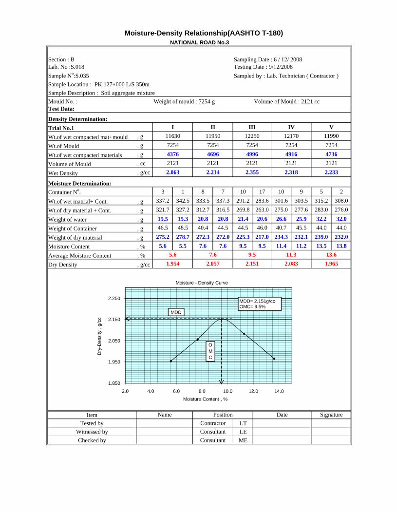
There is another borrow area of lateritic gravel No II, Location PK 127 offset 350m L/S , The material from
this borrow area was used for the construction of National Road 3 from Phnom Penh to Kampot.
Analyses of sample No. S035 from the laboratory give the following results:
Gradation % 200 pass 18.7 – 19.8 Alterberg limits LL PI
32 – 34 14 – 16
Los Angeles test % abrasion
47.4
Density MDD %W OMC
2.151 9.5
CBR, Rates 44 All results are conforming to the Cambodian construction specifications.
(See Attachment 8 ‐ Laboratory Test Results of sample No. S035).

ADB/GMS‐SCCP CW1&CW2 Mission Report of Material for NR33 and NR3 Egis International
10 | P a g e
3. Conclusion‐ Existing subgrade materials of the entire length of NR33 are not unsuitable materials except for
some very few locations only. But the existing subgrades of NR33 are too wet and saturated, not
possible for compaction. So Contractor may have to wait till it dried up and have the correct OMC
and at the meantime, Contractor should seek for areas where the existing subgrades have correct
OMC and suitable for compaction, so they can continue their works on these areas without staying
idle.
‐ Lateritic gravel from THKOW Mountain are good materials and possible for use as subgrade and
sub‐base.
‐ The quarry and crushing plant is located ~500m from Engineer site camp along road No 33.
Materials from this quarry are good for concrete but not good for base course or for DBST crushed
aggregates. First, is the quality of material that only the fresh black rock at the bottom/base of the
mountain are correct for hardness (LA) ‐ Second, the method of the present production is not
correct, material with correct gradation and flakiness cannot be produced.
‐ Provision list of laboratory equipment for NR33 by the Contractor is not complete and should follow
section 2.3 and Attachment 6 – Laboratory Equipment for SCCP – CW1 Contract.
‐ For stability of verge/margin of NR3, the used of lateritic gravel shall be the most suitable. Lateritic
gravel can be found from 2 borrow areas as specified in section 2.4.

Attachment 1 – AASHTO M145‐91


Attachment 2 ‐ Laboratory Test Results of Existing Subgrade Materials of NR33

Available in Hard Copy Only

Attachment 3 ‐ Site Photos of Investigation Pits


Attachment 4 ‐ FICHE GITE MATERIAUX

Available in Hard Copy Only

Attachment 5 – Proposed list of Laboratory Equipment from Contractor

Available in Hard Copy Only

Attachment 6 – Laboratory Equipment for SCCP – CW1 Contract

Available in Hard Copy Only

Attachment 7 – Photos of the borrow pit and quarry of materials for NR3


Attachment 8 ‐ Laboratory Test Results of Sample No. S035

LOS ANGELES ABRASION TEST (AASHTO T - 96)
EDCF Loan No . KHM-6
Section : B Sampling Date :5/12/08
Lab No : S018 Testing Date :12/12/08
Sample No : S035 Sampled by : Lab. Technician
Location :PK 127+000 L/S 350m
Description : Soil Aggregate Mixture
Grading No : C No .of Spheres Used :8
Cycles : 500 1
Initial Weight : A Kg 5000 5000
Weigth Retained
After Test on B Kg 2719 2541
No .12 ASTM Sieve
% of Wear by Weight A - B x 100
Passing No . 12 ASTM Seive A
Average Loss ( % )
Remark : < 50 % Acceptable to use for Sub-base Materials
Item Name
Tested by LT
Witnessed by LE
Checked by ME
2
47.4
45.62 49.18
NATIONAL ROAD No. 3
Consultant
Position Date Signature
Contractor
Consultant
Moisture-Density Relationship(AASHTO T-180)
Section : B Sampling Date : 6 / 12/ 2008Lab. No :S.018 Testing Date : 9/12/2008
Sample No:S.035 Sampled by : Lab. Technician ( Contractor )
Sample Location : PK 127+000 L/S 350m
Sample Description : Soil aggregate mixture
Test Data:
Wt.of wet compacted mat+mould , g
Wt.of Mould , g
Wt.of wet compacted materials , g
Volume of Mould , cc
Wet Density , g/cc
3 1 8 7 10 17 10 9 5 2
Wt.of wet matrial+ Cont. , g 337.2 342.5 333.5 337.3 291.2 283.6 301.6 303.5 315.2 308.0
Wt.of dry material + Cont. , g 321.7 327.2 312.7 316.5 269.8 263.0 275.0 277.6 283.0 276.0
Weight of water , g 15.5 15.3 20.8 20.8 21.4 20.6 26.6 25.9 32.2 32.0
Weight of Container , g 46.5 48.5 40.4 44.5 44.5 46.0 40.7 45.5 44.0 44.0
Weight of dry material , g 275.2 278.7 272.3 272.0 225.3 217.0 234.3 232.1 239.0 232.0
Moisture Content , % 5.6 5.5 7.6 7.6 9.5 9.5 11.4 11.2 13.5 13.8
Average Moisture Content , %
Dry Density , g/cc
3
Item
Tested by LT
Witnessed by LE
Checked by ME
Signature
1.965
13.6
NATIONAL ROAD No.3
Mould No. : Weight of mould : 7254 g Volume of Mould : 2121 cc
7254
47364916
2.318 2.233
2121
11950 12250
7254 7254
IV V
11990
7254
1217011630
2.083
5.6 7.6 9.5 11.3
Container No.
Density Determination:
Trial No.1 I II III
1.954 2.057 2.151
4376
Name Position Date
2121
Moisture Determination:
2121
2.063 2.214 2.355
Contractor
Consultant
Consultant
7254
2121 2121
4696 4996
1.850
1.950
2.050
2.150
2.250
2.0 4.0 6.0 8.0 10.0 12.0 14.0
Dry
-Den
sity
, g
/cc
Moisture Content , %
Moisture - Density Curve
OMC
MDD
MDD= 2.151g/ccOMC= 9.5%

Section : BLab.Nº : S 003 Sampling Date : 05/12/2008Sample Nº : S 035 Testing Date: 11/12/2008Location : 127+00 L/S 350m Sampled By : Lab. TechnicianDescription : Soil Aggregate mixture for Sub-Base Materials
Compaction Data :
Wt.of compacted wet materials+Mould g
Wt of Mould g
Wt of wet materials in mould g
Volume of Mould cc
Wet Density=wt.of wet compacted materials/volume of mould
g/cc
Moisture Content %
Dry Density=Wet Density/(1+m/100) g/cc
Moisture Determination :
No. of blows per layer
Moisture Can No. 17 10 1 3 A10 7 7 9 11 1 10 17
Weight of Can+Wet Materials g 296.6 321.3 329.3 315.1 332.2 327.2 316.4 344.7 319.1 279.7 282.7 349.9
Wt of can +Dry Materials g 276.1 299.2 305.2 294.2 308.4 303.6 285.5 310.5 290.0 255.3 259.5 320.5
Wt of Moisture g 20.5 22.1 24.1 20.9 23.8 23.6 30.9 34.2 29.1 24.4 23.2 29.4
Wt of can g 46.0 40.7 48.5 46.5 44.5 44.5 44.5 45.5 43.0 48.5 44.5 46.0
Wt of dry materials g 230.1 258.5 256.7 247.7 263.9 259.1 241.0 265.0 247.0 206.8 215.0 274.5
Moisture content % 8.9 8.5 9.4 8.4 9.0 9.1 12.8 12.9 11.8 11.8 10.8 10.7
Average Moisture Content %
Remark : used before soaking compaction for computation
Item
Tested by LT
Witnessed by LE
Checked by MEConsultant
Name Signature
Contracror
Consultant
Position Date
9.1
2.204
8492
5298
2204
2.404
8623
4617
8779
5001
8.9
2.053
2237
2.2362.091
8.7
8.7
1.923
8.9
30
9.1
1.913
After soaking
12.9 11.8 10.8
2.044 2.207
Before soaking
10
2.159 2.285
2208 2237
13890
E
8779
4767 5111 5388
2204
No. of Blows per layer
Mould No.
13780 13790
2208
13880
8492
10.8
10 30 65
2.445
12.9 11.8
8623
65
Moisture-Density Relationship (AASHTO T-180)
NATIONAL ROAD No.3
D E F
10 Blows 30 Blows 65 Blows
D
13240
F
13390
After soakingBefore soaking
10 Blows 30 Blows 65 Blows
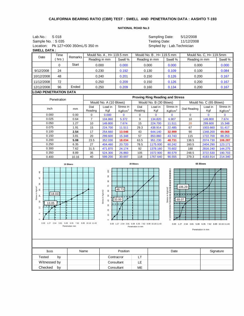
Lab.No.: S 018 Sampling Date: 5/12/2008Sample No. : S 035 Testing Date: 11/12/2008Location: Pk 127+000 350mL/S 350 m Smpled by : Lab.TechnicianSWELL DATA :
Swell % Swell % Swell %
0 Start 0.000 0.000 0.000
9/12/2008 24 0.192 0.109 0.084
10/12/2008 48 0.201 0.126 0.167
11/12/2008 72 0.209 0.126 0.167
12/12/2008 96 Ended 0.209 0.134 0.167
mmDial
ReadingLoad in
KgfStress in
Kgf/cm2Dial
ReadingLoad in
KgfStress in
Kgf/cm2 Dial ReadingLoad in
KgfStress in
Kgf/cm2
0.00 0 0.000 0 0 0 0 0 0 00.64 7 104.860 5.372 9 134.820 6.907 10 149.800 7.6741.27 10 149.800 7.674 15 224.700 11.511 20 299.600 15.3481.91 15 224.700 11.511 29.3 438.914 22.485 67 1003.660 51.417
2.54 17 254.660 13.046 43 644.140 32.999 90 1348.200 69.0683.81 20 299.600 15.348 57 853.860 43.743 115 1722.700 88.253
5.08 23.5 352.030 18.034 63.5 951.230 48.731 138.5 2074.730 106.2876.35 27 404.460 20.720 78.5 1175.930 60.242 160.5 2404.290 123.1717.62 31.5 471.870 24.174 92 1378.160 70.602 188 2816.240 144.2758.89 35 524.300 26.860 105 1572.900 80.579 248.5 3722.530 190.703
10.16 40 599.200 30.697 118 1767.640 90.555 279.3 4183.914 214.340
LT
LE
MEConsultant
Item Signature
Tested by
Witnessed by
Checked by
Contracror
Consultant
CALIFORNIA BEARING RATIO (CBR) TEST : SWELL AND PENETRATION DATA : AASHTO T-193
DateTime ( hrs )
RemarksReading in mm
inch
0.250
LOAD PENETRATION DATA
Name
NATIONAL ROAD No.3
0.000
0.025
Position
0.050
0.075
0.100
0.350
0.300
0.250
Mould No. A , H= 119.5 mm Mould No. B , H= 119.5 mm Mould No. C, H= 119.5mmReading in mm Reading in mm
PenetrationProving Ring Reading and Stress
Mould No. A (10 Blows) Mould No. B (30 Blows) Mould No. C (65 Blows)
0.000
0.230
0.240
0.250
0.000
0.130
0.000
0.100
0.200
0.200
0.200
0.150
0.160
0.150
0.150
0.200
0.400
Date
06
1218
2430
3642
48
0.00 1.27 2.54 3.81 5.08 6.35 7.62 8.89 10.16 11.43
Str
ess
in K
g/cm
2
Penetration mm
10 Blows
010
2030
4050
6070
8090
100
0.00 1.27 2.54 3.81 5.08 6.35 7.62 8.89 10.16 11.43
Str
ess
in K
g/cm
2
Penetration in mm
30 Blows
010
2030
4050
6070
8090
1001
1012
0130
14015
0160
1701
8019
02002
10
0.00 1.27 2.54 3.81 5.08 6.35 7.62 8.89 10.16 11.43
Str
ess
in K
g/cm
2
Penetration in mm
65 Blows
69.07
106.2948.73
33.00
18.03
13.05

Stress at 2.54mm= 13.05 Stress at 2.54mm= 33.00 Stress at 2.54 mm= 69.07
Stress at 5.08mm= 18.03 Stress at 5.08mm= 48.73 Stress at 5.08mm= 106.29
CBR = ( Corrected Unit Load / Standard Unit Load ) ×100, Standard Unit Load : @ 2.54mm = 70.38Kg/cm2
10 30 65
Corrected CBR - Density Plotting Data Dry-Density , g / cc 1.923 2.053 2.204
Corrected CBR ( %) 18.54 46.89 98.14
LT
LE
ME
CBR at 2.54 mm Penetration level
ConsultantChecked by
Signature
Tested by
Witnessed by
Contracror
Consultant
Item Name Position Date
NATIONAL ROAD No.3
No.of blows
CBR =
18.54
17.17 46.38
CBR CaculationsCBR = % CBR = %98.14%
CBR Test (AASHTO T-193)
CBR =46.89
CBR Calculation :
%101.17CBR = %
@ 5.08mm = 105.06 Kg/cm2
CBR =%
10
20
30
40
50
60
70
80
90
100
1.850 1.900 1.950 2.000 2.050 2.100 2.150 2.200 2.250 2.300
CB
R in
%
Dry Density , g/cc
Dry-Density Versus CBR Curve
44% CBR at 95 % of MDD
10 blows
30 blows
65 blows
Dry-D at 95 % of MDD=2.043g/cc

Summary of Test Result(Sub-Base)
• National Road No.3
1. Description
2. Test Result
3. Engineer's Comment
4. Certification
Position Date Signature
Tested by Contractor
Consultant LE
Checked by Consultant ME
LT
Item Name
Witnessed by
Consultant KCI with YEC, KCEC & VIDO
Contractor KukDongEC with HHI
Test Result
Specification
5/12/2008
less than 50
- - more than 30
Approved by
Decision
E.C.Kim Consultant RE
O.K O.K - O.K
8/12/2008
Pk 127+00 LHS, 350 m
O.K - - O.K
1832-34
5 - 20less than
35 -less than
20
PILL PLOMC (%)
18.7-19.8 449.52.1514714-16
B - 17, Pit-1 LocationBorrow Pit No.
4. Proctor5. CBR
(%,95% MDD)MDD (g/cc)
Item
2. Atterberg Limit (%)1. Gradation
(%, #200 pass)
3. LA Abrasion
(%)
Sample No. 035 Date of Test
Lab No 018 Date of Sampling

Trial No.1
Section No : B
Lab.Nº : S 018 Sampling Date : 5/12/2008Sample Nº : S 035 Testing Date : 8/12/2008Location : PK 127+00 , L/S 350m Sampled By : Lab. Technician Description : Soil Aggregate Mixture for Sub-Base Materials
Lower Limit Upper Limit Actual by test50.0 100 100 100.025.00 75 95 87.810.00 40 75 61.62.00 20 45 32.40.425 15 30 27.30.075 5 20 19.8
Comments : Acceptable for grade " B " of Table 3.1-1 of Construction Specification .
Contractor LT
Consultant LE
Consultant ME
SIEVE ANALYSIS OF FINE AND COARSE AGGREGATE (AASHTO T-27)
Grading Requirement for Soil Aggregate Materials ( Table 3.1-1 of Constr. Specifications )
NATIONAL ROAD No.3
Percent by weight passing square mesh sieves
Sieve Sizes (mm)
Date Signature
Tested by
Item Name
Checked by
Position
Witnessed by
0
10
20
30
40
50
60
70
80
90
100
110
0.0 0.1 1.0 10.0
% P
assi
ng
Sieve Size mm
Grading for Sub-base Materials (Table 3.1-1)
Lower Limit Upper Limit Actual by test

Trial No.2
Section No : B
Lab.Nº : S 018 Sampling Date : 5/12/2008Sample Nº : S035 Testing Date : 8/12/2008Location : PK 127 +00, L/S 350m Sampled By : Lab. Technician Description : Soil Aggregate Mixture for Sub-Base Materials
Lower Limit Upper Limit Actual by test50.0 100 100 100.025.00 75 95 92.010.00 40 75 59.42.00 20 45 31.20.425 15 30 26.50.075 5 20 18.7
Comments : Acceptable for grade " B " of Table 3.1-1 of Construction Specification .
Contractor LT
Consultant LE
Consultant ME
NATIONAL ROAD No.3
SIEVE ANALYSIS OF FINE AND COARSE AGGREGATE (AASHTO T-27)
Grading Requirement for Soil Aggregate Materials ( Table 3.1-1 of Constr. Specifications )
Witnessed byChecked by
Item
Sieve Sizes
Percent by weight passing square
Name Position Date Signature
Tested by
0
10
20
30
40
50
60
70
80
90
100
110
0.0 0.1 1.0 10.0
% P
assi
ng
Sieve Size mm
Grading for Sub-base Materials (Table 3.1-1)
Lower Limit Upper Limit Actual by test

ATTERBERG LIMITS ( AASHTO T- 89/T- 90 )
AND SOIL CLASSIFICATION
NATIONAL ROAD No. 3
Section :B Sampling d
Lab.Nº : S018 Testing D
Sample Nº : S035 Sampled Lab. Technician
Location : 127+00 LHS 350 m
Description : Mix aggregate for Sub-base material T-2
38 30 25 19 15
13 10 A14 7 15 A2 18
W1 g 33.02 34.4 35.3 36.29 37.01 29.59 31.12
W2 g 30.22 31.34 31.87 32.47 32.58 28.06 29.67
W3 g 20.5 21.22 21.3 21.4 20.4 19.5 21.7
W4=W1 - W g 2.8 3.06 3.43 3.82 4.43 1.53 1.45
W5=W2 - W g 9.72 10.12 10.57 11.07 12.18 8.56 7.97
W6=W4/W % 28.81 30.24 32.45 34.51 36.37 17.87 18.19
LL %
PI=LL - P %
LT
LE
ME
5/12/2008
8/12/2008
14.42Plasticity Index
32.45
Plastic LimitLiquid Limits
Wt of dry soil
Moisture Content
18.03
Wt of dry soil and
Wt of water
Can No.
Wt of wet soil and
Date
No. of Blows
Wt of can
Liquid Limit (from
Signature
Tested by
Witnessed by
Checked by
Contractor
Consultant
Consultant
Item Name Position
20.00
22.00
24.00
26.00
28.00
30.00
32.00
34.00
36.00
38.00
40.00
10 15 20 25 30 35 40
Mo
istu
re (%
)
Number of Blows
Blow - Moisture Graph