royal signals se'stablishment · 4.3. generalised sidelobe canceller (gslc) 5 5. ... dependent...
TRANSCRIPT

S.......- •UNLIMITED I
RSRE0MEMORANDUM No. 4410
ROYAL SIGNALS & RADARSE'STABLISHMENT
IMPLICATIONS OF ADAPTIVE CANCELLATION ARRAY PROCESSINGFOR DESIGN OF A SPACE-BASED SURVEILLANCE RADAR
Authors: J LMather, A C Fairho*4 & M P Wardhn
PROCUREMENT EXECUTIVE,UINISTRY OF DEFENCE,
0 1Bz IRSHE MALVERN,
OTIAtELECT'Ez W~ibMARO.4I M",U
"= 91 2 28 065
• ,-•---X *V -1 UNLIMITEDApprved for pubft nUq
IUtr*mb tU iitWd , I __ _ _ _ _ _ _ _ _ _ _ _ _ _ _ _ _ _ _ _ _ _ _ _

CONDITIONS OF RELEASE
0091388 BR- 16334
RIC U
COPYFIIGHIT (cO1988CONTROLLIERIIMSO LONDON
S......* ... .**A'*.. .. * DRIC Y
Rleport,' quoltod are not necessarily available to members of Ihe public or to commercialorganisations.

ROYAL SIGN _ 3 AND RADAR ESTABLISHMENT
Memorandum 44 10
IMPLICATIONS OF ADAPTIVE CANCELLATION ARRAYPROCESSING FOR DESIGN OF A SPACE-BASED
SURVEILLANCE RADAR
J L Mather, A C Fairhead, M P Warden
January 1991
SUMMARY
We examinc the system design issues associated with the use of adaptive jammer rejection in thc context ofpossible specifications for a spacc-based surveillance radar, We show that the adaptive nulling requirements ofthe system cannot be considered in isolation. Adaptivc processing has implications for the entire system, fromdesign of the antenna array, through to the choice of ADCs and the requirements of subsequent coherentintegradion and dcetection processing. Three different classes of adaptive processing architecture are considered:the sidolobe canceller, the fully adaptive array, and the generalied siddlobe canceller. These are shown to achievedifferent trade-offs between inherent complexity, requirement,;s upon the system specification, flexibility andperformance.
Copyright
Controller HMSO London
1991

THIS PAGE IS LMF BLANT, LN7ENTrIONALLY

CONTENTS
1. INTRODUCTION 1
2. REVIEW OF SPACE-BASED RADAR CONSTRAINTS 1
3. BEAMFORMING REQUIREMENTS 24. ADAPTIVE CANCELLATION SCHEMES 2
4.1, SIDELOBE CANCELLER (SLC) 24.2. FULLY ADAPTIVE ARRAY (FAA) 4
4.3. GENERALISED SIDELOBE CANCELLER (GSLC) 55. COMPARISON OF NULLING SCHEMES 5
5.1. PARTITIONING OF THE PHASED ARRAY 55,1.1, DEGREES OF FREEDOM 55.1,2. GRATING LOBES 65.1.3, DISPERSION 65.1.4, RELIABILITY 65.2. RECEIVER CHANNEL CHARACTERISTICS AND ADC REQUIREMENTS 75,2.1, CHANNEL MATCHING 75.2,2, DYNAMIC RANGE 75.2,3. TAPERING 105.2,4. BANDWIDTH 115.3. OTHER PROCESSING ISSUES 115.3.1. NUMBER OF DIGITAL OPERATIONS 115.3.2. CONSTRAINTS AND ROBUSTNESS 115,3.3. CONVERGENCE RATES 125,3.4. FLEXIBILITY 135.3.5. CHOICE OF ADAI7rIVE ALGORITHIM AND ARCHITECTURE 136. SUMMARY 14
7. REFERENCES 1 f
APPENDIX, DETERMINATION OF SIGNAL-, CLUTTER-, AND JAMMFh'TO- 19NOISE RATIOS AT ANTENNA ELEMENTS
uI t o tbu sIon/i
_ _ _ 1 .. ......... For,:,,

THIS PAGE IS LEFI' BLANK INTENTIONALLY
1. INTRODUCTION
Fundamentally, a radar is a signal processing system, The distribution of antenna elements andsub-arrays defines a spatial sampl ng pattern; the individual elements apply a frequency and angledependent complex weighting tm signals; signals are then amplified, filtered and re-weighted,demodulated, adaptively combined and detected; the transmitted signal must be designed to matchlikely propagation conditions, to confuse countermeasures, and to achieve the best match to aparticular type of target; the receiver must be matched to the expected return sigsl for optimumdetection. Thus, the signal processing function is now seen as central to radar systems, involvingthe design of the waveform, antenna and information processing algorithms. This is in contrastwith the traditional view which distinguishes between the "system" and the "sigiýal p-octsing",the latter being thought of as a back-end "black box" component. Convention -, -lars are analoguesignal processors, whilst the current trend is towards the increased use of die_•.u tchnologv,
Although the signal processing required for a radar may be broken down into small blocks, thefunctionality of each block must be designed with the requirements of others in mind. Evaluatingthe choices available, and the consequent inter-relationships between such blocks, becomesincreasingly complex when one considers multi-channel arrays, The decision to adopt adaptivenulling may affect the structuring of the antenna itself (design of subarrays, for example) therequired digital wordlength in the ADC or output power, or may necessitate different ordering orpartial duplication of other functions such as clutter rejection, Conversely, the choice of adaptivenulling scheme will be influenced by the practical constraints imposed by a given application,Whilst we have much experience of thinking about the structure of conventional radar signalprocessing chains, we have rather less knowledge concerning the integration of modern techniquessuch as adaptive nulling into multi-element systems.
This paper will present a review of the implications of alternative adaptive nulling architectureson the design of a space-based look-down radar, based on typical practical considerations, We willreview the major constraints imposed by a space-based application in section 2, and summarise thebeamforming requirements of such a system in section 3. Section 4 will define the sidelobecanceller and fully adaptive sub-arrayed nulling approaches and make further assumptions aboutthe implications for hardware, In section 8 we will compare these alternative nulling schemes inmore detail, taking as a basis the way in which they influence or are influenced by the partitioningof the phased array, receiver channel characteristics, ADC requirements, and other signalprocessing issues such as number of digital operations and convergence rates, Finally, in section 6,we will summarise the major advantages and disadvantages of each adaptive scheme for the space-based radar.
2. REVIEW OF SPACE-BASED RADAR CONSTRAINTS
In order to draw any useful conclusions, we must make some basic assumptions about the requiredradar specifications and the nature of the jamming threat and clutter environment which it will berequired to deal with. These assumptions are made for the purpose of illustration, and are notmeant to correspond to any operational design or requirement. Below, we summarise the detailgiven in the Appendix,
The radar will combine search and tracking functions, interleaved according to some radar controlalgorithm. Following detection, immediate look-back would be useful to confirm and to initiatetracking, A phased array will be necessary to achieve the beam agility required for such a system.We will assume a two-dimensional L-band (26cm) array containing 16384 elements (a convenientpower of two). We will chose the array to be 28mx9in in size, giving an area of 24dBm 2, azimuthand elevation beamwidths will be approximately 1.7* and 0.5', respectively, A rectangular array,with its longer dimension aligned to the direction of travel, is chosen to ameliorate ground clutterreturns, Peak total power will be 100kW, and the transmission will be of a range-ambiguous pulse-Doppler waveform, We assume a few loms coherent bursts before the beam moves on to a newposition. We will chose signal bandwidth to be 1MHz, varying over a 200MHz agile bandwidth.
11

As can be seen from the detailed calculations in the Appendix, we will assume a range of possibletarget signal-to-noise ratio (SNR) between .98dB and .69dB at each antenna element, dependingon the angle of scan, the size of the target, and losses. We estimate the likely main beam clutter tonoise ratio (CNR) at the element to lie between -39dB and -13dB. Powerful ground-basedjammerswill be able to transmit into the antenna sidelobes over the full agile bandwidth, giving a jammingto noise ratio (JNR) of around 59dB, Less powerful airborne jammers may be able to transmit intothe main beam over the full agile bandwidth, resulting in a maximum JNR of around 4dB at theelement,
3. BEAMFORMING REQUIREMENTSIf we consider the integration of adaptive nulling with otherwise fairly "conventional" signalprocessing, we will need a sum beam and two difference beams for two-axis monopulse, andsidelobe blanking channels, Because of the nature of the system, ground clutter returns ofsignificant bandwidth will be present in the data, and some form of clutter cancellation scheme willbe necessary, This will not be considered in detail in the present memorandum, However, if weconsider using the displaced phase centre antenna (DPCA) (1) technique for clutter removal, thenall the beamforming hardware (apart from the second difference beam, which would no longer berequired) must be duplicated for each of the two (or more) DPCA channels, We must maintain ahigh gain mainlobe in the sum beams for SNR enhancement (42dB with sixteen thousandelements), and a notch at boresight in the difference beams for accurate angle estimation. Arandom sidelobe floor' of .15dBi must be achieved, partly for the suppression ofsidelobe clutter, butparticularly for the suppression of sidelobe jamming, which even then will have to be adaptivelynulled by a further 50dB or more in each beam, Mainlobe jamming must be nulled by a similaramount.
We will assume for the purpose of subsequent analysis that. 32 degrees of freedom will be sufficientto cope with the likely jamming threat, This choice will influence the settling time of the adaptiveprocess, the peak sidelobe level (which must be minimised) and the stability of the beam pattern,A stAble beam pattern is necessary to avoid modulating clutter, A smaller number of adaptivechannels would be suitable if only a limited number ofjammers are likely to be encountered. Thiswould lead to faster convergence of the adaptive algorithm, On the other hand, a larger number ofchannels would also be technologically feasible,
4, ADAPTIVE CANCELLATION SCHEMES
We consider adaptive antenna schemes to fall into three broad categories, In each caise, the phasedarray will be divided into sub-arrays in order to reduce the number of degrees of freedom from16000 to a more reasonable number (taken to be 32 for this study),
4.1. SIDELOBE CANCELLER (SLC)The sidelobe canceller makes use of one or more directional "main beams" and a number of lessdirectional, lower gain "auxiliary beams". The main sum and diffprence beams would be formed byanalogue beamformers, making use of the majority of elements in the array, The rcmainingelements may be taken singly or in smaller sub-arrays to form the auxiliary beams, Each elementof a main beam will be subject to a fixed analogue beam -tapering weight, which is designed to lowerthe "natural" sidelobes of the beam [2), In general, the auxiliary channels may or may not have zerogain on boresight, although in our system they need zero gain for the difference beam, Adaptiveprocessing will change the unadapted beam shapes, Nulling signals which are in the main beamregion could cause significant skewing of the main beam pattern. The maintenance of high sum-beam and zero difference-beam gain on boresight, following adaptive processing, relies on theauxiliaries having much lower allowable gain than the main beam, This also prevents the effectivenulling ofjamming signals entering the main beam and thus minimises the likely distortion of thatbeam,
As shown in Fig. 1, associated with each main and auxiliary beam is a receiver channel, containing
2

Sum-beamcombiner
S~Sum beam I
DPCA •'
Aperture1 Diff beam 1
>--"Diff-bearn
combiner AdaptiveSub array W "]Aatv
cominers 1 combiners
Auxiliaries
>- F 7_
DPCA Sum beam 2
Aper'ture
) Diffrbeam 2
Fig. 1. Architecture of adaptive sidelobe canceller. The two main apertures are required for DPCAclutter processing.
signal-bandwidth-defining filters and ADCs. The adaptive algorithm will be implementeddigitally. DPCA requires an extra, displaced main aperture and therefore the duplication of eachmain receiver channel, Although they are shown separated for clarity, the two main apertureswould overlap considerably in practice, most elements contributing to both with their outputs splitfour ways via programmable attenuators. The auxiliary channels do not need to be duplicated: theycan be adaptively combined with signals from both main apertures for sidelobe cancellation.
DPCA processing, Although not shown, is assumed to follow adaptive beamforming, but there is noobvious reason why these two processes should not be reversed, It will csrtainly be necessary forclutter to be removed from the data which is to be used for the adaptive weight cumputation. This
3
DPCAAperture
AD Diff
beam 2
DPADC
beam 2
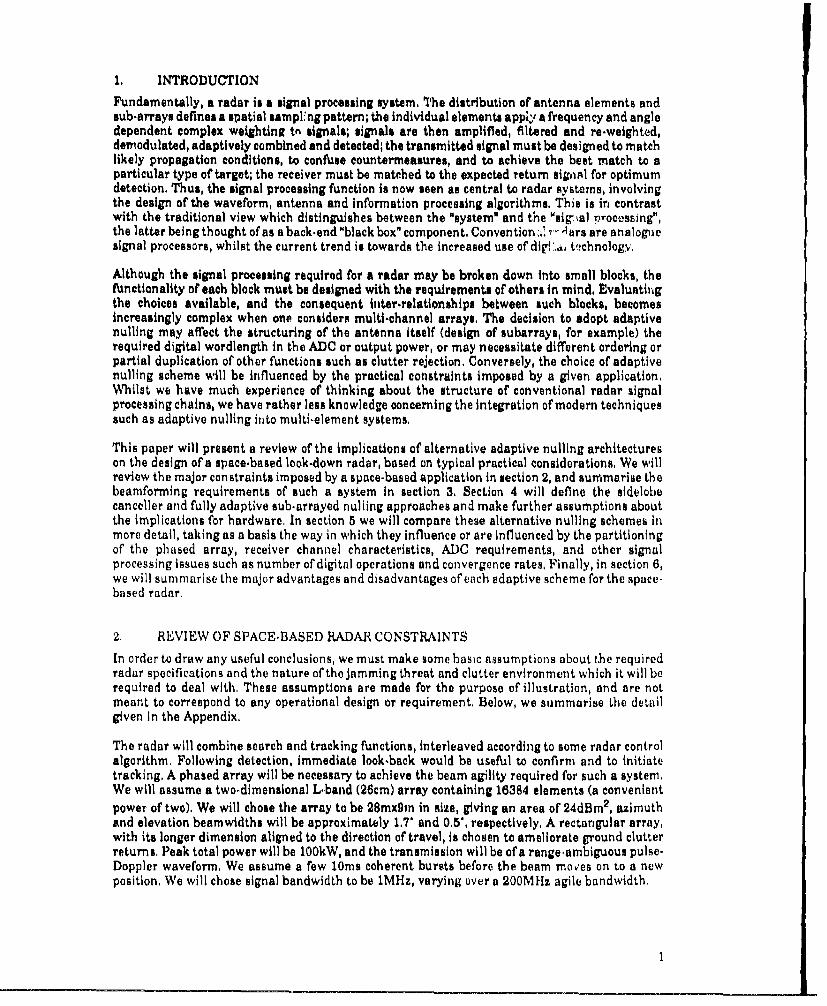
Fig. 2, Architecture for a fully adaptive subarrayed antenna, Each subarray is treated equally,apart from any overall aperture weighting function, The two main apertures are required for DPCAclutter processing,
will prevent adaptive degrees of freedom being used for clutter cancellation, and maximise thoseavailable to remove jamming,
4.2. FULLY ADAPTIVE ARRAY (FAA)
It is clearly impractical and unnecessary to make use of sixteen thousand degrees of freedom, andso a true fully adaptive array is not being considered here. Instead we mean an array which hasbeen divided into a number of equivalent subarrays, each of which contributes a degree of freedom,These degrees of freedom are used either in the adaptive processing, or to control the beamshapethrough programmable constraints,
As shown in Fig. 2, the signal from each element of the array would be split and subjected t~oanalogue beam-tapering weights before being fed to two different sub-array outputs, one that isoptimised for contributing to a sum beam and the other to a difference beam. Each sub-arraychannel would then have its own receiver channel, containing downconverters, signal-bandwidth-defining filters and ADCs. The adaptive algorithm will be implemented digitally, although theadapted weights may be either digital or analogue. Each main beam is formed through the actionof a directional constraint on the adaptive weight calculation. Normalisation of the weights with
4

respect to the desired signal level at the output will cause the "gain" in the desired signal directionto be fixed, This does not imply that the output signal to noise ratio of an adapted system willalways be the same as that which can be achieved by a fixed-weight system which is not subjectedto Jamming, For example, the suppression of main-beam jamming will cause an increase in thenorm of the weight vector in order to meet the desired output signal level, and this will result inamplification of the system noise.
The inclusion of DPCA does not necessarily mean that the number of subarray channels must bedoubled. That number was fixed at 32 for adaptivity, not for beamforming purposes. It mighttherefore be possible to redistribute the subarrays so that four sets of eight are each optimised forcontributing to either a sum or difference beam at one of two phase centres. As in the SLC, theoutputs from most elements would therefore be split four ways via programmable attenuators, Alsoas discussed for the SLC, it will be necessary to remove clutter from the data used by the adaptiveweight computer. This is not shown in the diagram, and, although important, methods for clutterremoval are not explicitly considered in this memorandum.
4.3. GENERALISED SIDELOBE CANCELLER (GSLC)
In this configuration, all antenna elements will be used to form the main sum and differencebeams. The same elements, grouped into smaller sub~arrays, will provide auxiliaries for adaptivenulling, Two sets of beam-tapering weights will be required to shape the main and sub.arraybeams. Ideally, the auxiliary beams will have zero gain in the main beam direction, in order tomaintain gain towards the desired signal following adaptation. It is likely, using currenttechnology, that both the main beams and auxiliaries will be formed using analogue beamformersbecause of the number of elements involved. The adaptive algorithm is again implementeddigitally, and it may be possible to apply additional constraints at this point,
The generalised sidelobe canceller of Griffiths and Jim [3) falls within this class of adaptivesystems. This system makes use of all elements for both the main and auxiliary channels, Theauxiliary channels are arranged to have zero gain in the main-beam direction, If the auxiliarybeams are orthonormal to the main beam, and all degrees of freedom are used, then the system willbe exactly equivalent, in principle, to a fully adaptive array having the same sub-array pattern,Mathematically, each is a linear transformation of the other, An alternative linear transformationof the fully adaptive array, proposed by McWhirter [4], leads to another generalised sidelobecanceller, which van Veen [5] has shown to be equivalent to a factored implementation of theGriffiths architecture.
5. COMPARISON OF NULLING SCHEMES
As shown by the figures in the Appendix, in all cases under consideration, the desired signal willbe below the noise level at the input to the adaptive nulling computation. This may be importantif the same data is used to calculate the adaptive weights, This is because the presence ofsignificant signal in or around the desired main beam direction causes some deterioration of theattainable output signal to noise ratio, As we shall see in section 5,2, the FAA has the capability toform nulls in the main beam and would be most sensitive in this respect, For the same reasons,main beam clutter must also be filtered below the noise level if it is not to capture adaptive degreesof freedom. In the Appendix clutter is shown as being above the noise level at the input to the ADC.For the purpose of comparing the nulling schemes, we will assume that it can be suppressed(perhaps using DPCA) prior to computing the adaptive weight vector,
5.1. PARTITIONING OF THE PHASED ARRAY
5.1.1. DEGREES OF FREEDOM
For greatest efficiency, in a two-dimensional phased array, sub-arrays must be positioned to givethe maximum number of degrees of freedom in all planes normal to the array, For example, if asixteen phase-centre array is arranged on a regular 4x4 grid, then only four degrees of freedom willbe available in the principal planes. Flam 16] has shown how this effect may be simply understood,and concludes that a planar array consisting of 2M carefully placed phase centres should be able
5
to form a minimum of M nulls in a given conical region of interest. In the MESAR phased array 17],a sub-arrayed system, the phase centre spacings have been randomised for this reason. Similgrdesign rules will apply to the phase centres of a sidelobe canceller, in which it is likely that theauxiliaries will be distributed around the periphery of the main array.
5.1.2, GRATING LOBES
Sub-array placement will also be important from the point of view of grating lobes. These areimages of the main beam, pointing in other directions. They result, in general, from havingdistances between adjacent sub-array phase centres of greater than half of a wavelength- that is,spatial under-sampling, The presence or absence of grating lobes will be governed by theseparation of the phase centres as projected onto the plane of interest. It may be possible to ext-ndthe concept of minimum redundancy arrays [8] to the design of planar structures with widelyseparated phase centres. Grating lobes will cause problems with element-space adaptive systemssuch as the sub-arrayed FAA or GSLC, even though they may have been reduced to a level similarto the normal antenna sidelobes, Since a grating lobe is an image of the main lobe, in a FAA systemits behaviour will be governed by the directional gain constraint applied to the main beam, If ajamming signal is directed at such a lobe, the system will be unable to adapt against it effectively.This problem will not occur with the SLC, unless individual antenna elements are too widelyspaced, However, in either system, the creation of a null in the direction of a jammer may beaccompanied by the formation of grating nulls in other directions. It is possible that these couldinteract with nulls directed against other jammers, Randomisation of the phase centre positionswill suppress both grating lobe and grating null effects,
5.1.3. DISPERSIONPhase dispersion across the aperture, associated with wide-band signals located away fromboresight, will increase the number of degrees of freedom required to adapt against a singlejammer and may reduce the depth of the resultant null, These degrees of freedom may be spatial(occupying additional phase centres) or temporal (requiring adaptive FIR filters in each adaptivechannel), Any increase in the number of degrees of freedom will cause an increase in the amountof hardware required, the digital computation load, and the time taken for the adaptive algorithmto converge and stabilise,
It has been suggested by Barton [9) that the SLC may be more sensitive to aperture dispersioneffects than the FAA because of the large distances between phase centres, Since the overallapertures of the SLC and FAA systems which we are considering will be the same, we have noreason to believe that the sensitivity to aperture dispersion would be any different in each of thetwo cases, However, Barton points out that the delay which ought to be considered must alsoinclude the antenna feed networks. In some systems, the SLC main array may have a longer feedthan that for the auxiliaries, causing the total delay to be much greater than implied by thephysical aperture, Compensation will be necessary, perhaps by introducing additional line lengthsinto the auxiliary channels, The feeds associated with the sub-arrays of the FAA would naturallyhave better-matched dispersive properties, More importantly perhaps, the complex patterns of theSLC main and auxiliary arrays will be different and will vary differently as a function of frequency,whereas the patterns of the FAA sub-arrays should match much more closely, This effect thereforemay increase the number of degrees of freedom required to null a given number ofjammers moresignificantly with the SLC than with the FAA,
5.1.4, RELIABILITY
Finally in this section, it is perhaps worth referring to reliability, This is a complex issue, whichwe do not propose to consider in any detail. However, it is clear from a simple example that thedifferent architectures implied by the different adaptive nulling schemes may have differentreliability characteristics. If the main beam summation node in the SLC or GSLC should fail, thenthe system will cease to operate. If a sub-array summing node fails in the FAA, then we would onlylose a single degree of freedom, in principle. However, this is a very specific failure, and appropriatehardware design could insure against it. An alternative view might be that the greater hardwarecomplexity of the FAA would lead to a higher probnbility of some type of failure, Another importantpoint is that failure of receiver channels during tho• lifetime of the system will have potentially
6

serious consequences for achievable random sidelobe levels. Although the adaptive control of theAidelobe pattern will work to minimise the impact of this, the dynamic range required of the ADCsmay have to be increased to take it into account (see Bection 5.2.2 for discussion of dynamic range).
5.2. RECEIVER CHANNEL CHARACTERISTICS AND ADC REQUIREMENTS
5.2.1. CHANNEL MATCHING
For optimal performance of the adaptive nulling system, it is important that the receiver channelsshould be well matched over the operating frequency band, for the same reasons as discussed inconnection with dispersion in the previoua section. The match should be maintained as a functionof signal amplitude and operating temperature, the latter implying a need for careful temperaturestabilisation in the severe conditions of space. Taking into account the antenna feeds and RFcomponents, matching may pose a problem in a sidelobe canceller system. However, the receiverchannelF for the FAA degrees of freedom are nominally the same as each other, and one mightexpect that this would simplify the matching problem. Nevertheless, matching the channels of aFAA to the accuracy required for sifective suppression of powerful ground-baced jamming may stillbe very difficult. In order to achieve null depths of 60 to 60dB, matching equal to 0, 1i rms in phaseand 0.015dB rms in amplitude is likely to be necessary. Such a degree of match is also likely to benec.ssary for effective DPCA clutter processing,
A major source of mismatch in receiver channels is likely to be the signal-band-defining filter. Eachchannel contains such an analogue filter, and whilst it may be possible to match the filters at band-centre, it will be significantly more difficult to match the phase characteristics in the band-passskirts. Although this mismatch may be minimised with careful design, it is likely 'hat furtheraction will be necessary, One possibility is to calibrate each channel ata number of spot frequenciesacross the band, and then to correct for differences using a digital FIR filter following the ADC, Ifthe filter is re-programmable, then this would potentially allow in-service re-calibration. Thematch would now be limited by the accuracy of the calibration and the resolution of the filtercoeflicients, Another approach, which Pohlig [10] has shown to reduce mismatch problems, is toadaptively control a set of analogue weights which precede the filters, This technique could be usedas well as or instead of the FIR filter described above, and could also be beneficial in reducingdynamic range requirements, as we shall see later in this section,
Another potential source of mismatch is in the ADCs themselves, For example, these may havenonlinear operating charadteristics, and will have to have carefully matched aperture times, In theSLC, we shall see that there is apparently potential for reducing the system cost by using ten-bitconvertors in the aaxiliary channels, whilst using a twelve-bit converter in the main channel.However, apart from the additional cost of manufacturing two different space-qualified ADCs, sucha scheme may introduce additional tracking problems associated with the inevitably differentcharacteristics of the two devices. The different quantisation steps of the two converters may alsocause problems. An alternative approach, which is likely to be possible in future, would be to use"single-bit" oversampling ("sigma-delta") converters. This would reduce the difficulties ofproducing a linear conversion characteristic, Such converters typically sample the analogue signalat many times the normal rate, to produce a pulse-density modulated stream of bits, which arethen digitally integrated to provide the required output digital wordlength. Converters based onsimilar principles, but using initial coding into three- or four-bit words in order to reduce thesample rate required, may be available for radar applications in the shorter-term.
5.2.2. DYNAMIC RANGE
For a FAA, the dynamic range requirement will be the same for each channel, whereas it will bedifferent for the main and auxiliary channels of the SLC. The SLC, expected to cope principallywith jammers in the sidelobes, will already have achieved a significant degree of jammersuppression through the tapered sidelobes of the main beam and the correspondingly lowerauxiliary channel gains, Thus, the wordlength requirements of ADCs should be eased, as will thoseof the adaptive cancellation computation,
The calculations given in the Appendix derive possible dynamic ranges of signals, as measured atthe antenna elements. By following these signals through the different architectures, as shoým in
7

Combiner
>_. 16384:1
>--- SNR gain 42dB ADC
Sidelobes -15dBi SNR gain 23dB
S~ADC
dB Main Auxiliary60-- Ground-based channel channels
jammer
40 -- M
20-- [70 - ..... Airibornejarnmer L
Noise-2
Level-20 - [ Clutter
-60 --
-80 -- 8Signal
-100 --
Fig. 3. Signal, clutter and jamming levels with respect to noise, in an adaptive sidelobe cancellerarray, such as that shown in Fig. 1. The upper chain corresponds to the mai channel, and the lowerchain to one of the auxiliaries. The powers shown at element level correspond to those given in theAppendix.
Figs. 3 and 4, we sce how the dynamic range changes us a result of subsequent processing. Forexample, in either the SLC or FAA systems, at the element level we find a possible worst-casetarget signal-to-noise ratio of around -98dB, and a worst-case jammer-to-noise ratio of around59dB. As we progress through each system, we find that the signal, jammer and clutter levels arechanged in different ways. For simplicity in the diagrams, we consider systems that form a sumbeam only.
8

Sub-array Combiner
512:1
>"- SNR gain 27dB ADC 32Sidelobes 7dBi 2Bea..id- th SNR gain 23dB channels
>-----B~eamwidth 5'
dB
60 - Ground-based -jammer
40 -
0- ....... Airborne jammer Noise
0 ZZ Level-20
-40 - Clutter
-60-
-80 -
-100 -Signal
Fig. 4. Signal, clutter and jamming le.vels with respect to noise, in a subarray channel of a fullyadaptive array, such as that shown in Fig. 2. The powers shown at element level correspond to thosegiven in the Appendix.
In the main sum-beam channel of the SLC, the gain of the mainlobe raises the minimum SNR to-56dB and the airborne JNR to 46dB, whilst the -15dBi tapered sidelobes reduce the ground-based-JNR to a similar level, The signal-band-defining filters cause a further increase in SNR to aminimum of -33dB in the main channel. Thus the dynamic range, defined by noise at one extremeand the maximum jammer or clutter level at the other, would probably allow us to work with a 12bit ADC, whilst still encoding sufficient information concerning the "noise plus signal" statistics toenable the system to integrate and recover the signal at a later stage of the processing. In addition,although the dynamic range requirement of the auxiliary channels would seem to be even greaterthan that of the main channel, it can in fact be lower. Since the only purpose of the auxiliaries isto pick up sidelobe jamming, their sensitivity can be reduced, using either an AGC or a fixedattenuator, in which case only 10 bits may be sufficient in principle. This will reduce the level of
9
airborne main-lobe jamming signals fed to the adaptive processor, and so reduce the capability tonull these signals. In an SLC system, this type of main.lobe jamming is likely to be difficult to dealwith in any case, because of the very high weight norm required to achieve sufficient null depth,Indeed, we have already accepted the inability to reject such signals by assxining a constraint onthe norm of the adaptive weight vector. In the presence of such malt, beam jamming, the SLC radarwould simply have to look elsewhere, and we must accept that this may enable an airborne jammerto deny important coverage to the radar, However, as mentioned in the previous section, usingdifferent ADCs in this way may exacerbate the problems of channel matching, and use of anattenuator of AGC is likely to offer a more suitable solution.
In order to reduce the dynamic range needed by the SLC main channel to deal with sidelobejamming, Pohlig [10] has proposed a hybrid analogue and digital nulling scheme in which somecancellation is achieved before digitisation. This is achieved without loss of SNR. The weightcomputer produces a set of analogue weights which are fed back to the auxiliary channels at a pointpreceding the analogue filters. Digital weights are fed forward and are found to improve theconvergence characteristics of the technique, Ward et I [II] have also described a related closed-loop feedback architecture, In both cases, we assume that the (digital) computation of the analogueweights will converge, given a starting point which may include signals which have been clippedby ADC overflow,
By contrast with the SLC, we see that the assumptions made concerning the characteristics of thesub-arrayed FAA lead us to a requirement for a 14 bit ADO in each of the 32 channels, This occursbecause the antenna beam pattern for the whole aperture is not formed until after adaption, andso we do riot have the pre-formed low sidelobe pattern of the SLC with which to gain someimmunity from jamming, Since it has not been amplified by a full main-lobe gain, the situation forairborne jamming might appear to be easier than with the SLC, However, it would still be difficultto null such jamming adequately since attenuating by 34dB, instead of providing 15dB of gain, asthe final stage of beamforming should, is equivalent to 49dB of cancellation, At the very least, thiswould cause severe distortion of the main beam and (more importantly and fundamentally) asignificant increase in the noise level following adaptation, due to the increase in the weight normneeded to create such a null, However, the system would still have maximised the output signal tonoise plus interference ratio, as required by the adaptive weight computation, and so the outputwould be an improvement over the quiescent un-adapted case.
The estimates of ADC dynamic range, discussed above, may have to be further modified to takeaccount of the likely increase in sidelobe levels resulting from channel failure and degradation overthe lifetime of the array, Yet another influence on the choice of digital wordlength may be thelikelihood of higher peak jammer powers caused by constructive interference of multiple jammers.To some extent, both of these effects are allowed for in the estimates given above, but would requirefurther analysis for a specific design,
5,2.3. TAPERINGThe ability to accurately "taper" the aperture, as described in section 4, to achieve low sidelobesimplies accurate knowledge of the channel calibration and match. In the case of the SLC, aperturetapering is clearly important in that it effectively partitions the task of sidelobe jammersuppression between a fixed analogue section and an adaptive digital section. This reduces thedynamic range of the receiver channels and the ADCs, and consequently reduces the wordlengthneeded in subsequent digital processing, As seen in the previous section, this benefit is notobtained in an FAA, even though tapering is applied at the elements. Nevertheless, Gupta andKsienski [12) have shown how tapering is equally important for the fully adaptive array, They havedemonstrated that the output signal to noise plus interference ratio (SNIR) depends on theconventional un-adapted beampattern, Therefore, lower quiescent sidelobes can result in a higheradapted output SNIR, However, for all the adaptive schemes under consideration it is worthremembering that aperture tapering to gain improved sidelobes will also lead to an increase in themain beam width, Since the SLC is unable to null jamming within the main beam, this will be alimitation and should be taken into account in deciding the physical aperture, Similar commentsapply to the FAA, as nulling main beam jamming can lead to a lower output SNIR than for sidelobejammers, as described above,
10

5.2A4. BANDWIDTHThis issue is related to the discussion on dispersion effects, To some extent, wide band jammingmay be nulled using spatial degrees of freedom, since the time taken for the signals to cross theaperture may provide the delay necessary for such processing, The number of degrees of freedomrequired will depend on the dispersion of the jamming signal across the aperture, which in turndepends on the bandwidth and angle of arrival of the jamming signal. Hudson [13] haa examinedhow degrees of freedom are used as a function of bandwidth, If it is known a priori that jammingsignals are likely to use up multiple spatial degrees of freedom, then adding further adaptivechannels to the system could provide a straightforward solution.
Perhaps a more natural solution to the problem of significant jammer bandwidth would be tosimultaneously adaptively adjust the combined spatial and frequency response of the channels.Given a signal requiring more than one degree of freedom to form a null, then there would be achoice of architectures for both the SLC and the FAA. One possibility would be to use an FF1 tobreak up the signal bandwidth, followed by multiple 'narrow band" adaptive canceller algorithmsacting on frequency cells containing significant power, This may have convergence performancesimilar to the narrow band case, but there is an obvious hardware penalty, An alternative wouldbe to carry out wide.band nulling using an adaptive tapped delay line architecture 114]. This islikely to converge more slowly because of the greater number of degrees of freedom, For the FAAand GSLC, constraints would need to be designed such that the frequency response of the adaptedsystem is unperturbed in the direction of the desired signal,
563. OTHER PROCESSING ISSUES
53.1. NUMBER OF DIGITAL OPERATIONS
Open-loop computation of the adaptive weight vector typically demands O(N3 ) complex numericaloperations, where N is the number of adaptive channels. Using combined parallel and pipelined(systolic) processing architectures, these operations can be carried out in 0(N) time steps, We haveconcluded in section 5,2 that the FAA will require longer digital wordlengths than the SLC in allchannels. Therefore, the subsequent digital processing must also use longer wordlengths. Thisimplies additional bit-level operations and may slow down the maximum processing rate. However,as we shall advocate the use of parallel or pipelined processors, possibly working in the datadomain, this is unlikely to be very significant. As the power of standard DSP chips continues toincrease, processing load is no longer thought to be a dominant issue in real-time system design,As Knowles et a] have shown [15], even recursive operations may be carried out at a rate which isindependent of wordlength.
5.3,2. CONSTRAINTS AND ROBUSTNESS
The shape of the main beam of the SLC will remain relatively undistorted following adaptation,This is because nulling of mainlobe jamming will be prevented, either by reducing the gain of theauxiliaries to such jamming, or by constraining the maximum adaptive weight norm (which mayrestrict the choice of adaptive algorithms in a digital processor). Since the auxiliary channel gains,including weighting, will be therefore much less than the gain of the main beam, mainlobeperturbations will be small. Thus, the shape of that beam is principally determined by the physicaldesign, electromagnetic properties and the analogue aperture tapering weights. The moreaccurately the antenna may be characterised, the more accurately the beamshape and mainchannel siAelobe levels may be predicted.
The main beam of the FAA is created after the application of adaptive weights, The gain in thedesired pointing direction is determined by a linear constraint on the calculation of the weightvector. Under quiescent conditions (in the absence of jamming), knowledge of the resultant beam-shape will again depend on how accurately the antenna and receiver system has been calibrated,and on the analogue aperture tapering function. Whilst adaption against sidelobe jamming will notgreatly perturb this shape, main beam jamming miy lead to significant distortion of the beam. Thiswould appear to have dire consequences for monopulse direction-finding. However, in principle, thedistortion can be predicted and corrected for [16], The extent to which this can be achieved dependson the proximity of the jammer to the con straint direction and on the JNR. The closer the jammer
11

is to the direction specified by the constraint, the higher the weight norm required to null it, andthe higher the dynamic range required of the digital part of the system, Although the beamdistortion may be corrected, and monopulse direction finding capability restored, the increasedweight norm will amplify the system noise. This means that the output SNIR will be lower than inthe presence of a sidelobejammer of the same power, and consequently the estimates of directionof arrival of the wanted signal will have greater variance.
If the desired signal is present above the system noise level in the data used to calculate theadaptive weights, the FAA becomes extremely sensitive to the accuracy of the beam-steeringconstraint. If the signal arrives from a direction different from that assumed, then the system willattempt tk null it, sharply reducing the output SNIR as well as distorting the beam (12], We haveshown in the Appendix that the signal in the present application will be below the noise, and sothis will not be a problem, If the desired main beam has the same shape as the SLC main beamthen sensitivity to error in the pointing direction will be determined by the rate of change of gainaround the nose of the beam, In general, this will be the same in each case, although beam skewingIn the FAA may lead to higher rates of change under some circumstances, For this application,additional constraints on the FAA, such as derivative constraints or additional gain constraints,are unnecessary and would only serve to reduce output SNIR, However, further "soft" constraints[17] may be useful in order to "tle.up" otherwise un-utilised degrees of freedom, thus reducing thetendency towards instabilities in the sidelobe pattern (discussed further in the following sub-section), Soft constraints are added to the data such that the adapted sidelobe pattern tendstowards that for the un.adapted system in regions not affeded by jamming,
Sidelobe clutter has not been mentioned so far in this memorandum, ror as far as we are aware inthe adaptive-nulling literature. It needs to be considered, however, because it will be above thethermal noise level in the SLC main channel and considerably more so in the FAA channelsbecause of their inferior sidelobe suppression, It will have a very wide Doppler spread, and may notbe removed efficiently by DPCA techniques because of the effects of mis-match between the twoantenna patterns, If such clutter cannot be rejected independently from the data used foradaptation, it will capture the degrees of freedom remaining after suppression of the strongestjammers, In this event, its effect would be simply to lower the general sidelobe level of the adaptedbeam. Given the limited number of degrees of freedom in a partially-adaptive system, such as theSLC or the FAA being considered here, this would adversely affect the ability to reject weakerjamming signals, and would, in any case, have a limited effect on spatially distributed clutter.Furthermore, a single set of adaptive weights needs to be calculated and used for a given coherentintegration period. If this is not done, a fluctuatting sidelobe pattern will result from the varyingsidelobe clutter, and any subsequent suppression of sidelobe prior to target detection will beadversely affected. This topic needs further examination,
5.3.3. CONVERGENCE RATESIt has been shown that an adaptive system using a direct algorithm for calculating the weightvector will converge to within 3dB of the optimum output SNIR within approximately 2N datasnapshots, where N is the number of channels, in the absence of the desired signal [ 181. This shouldbe true for both the SLC and FAA systems in the presence of sidelobe jamming, However, becauseof the additional gain constraint employed in the SLC the two architectures have differentbehaviour where beam patterns are concerned,
In the SLC, the main beam and its sidelobes are formed in advance of the adaptive processing, Thelimitation of auxiliary channel gain, through a norm on the adaptive weight vector, results in anadapted pattern which has sidelobes within a few dB of the quiescent pattern, In the FAA, on theother hand, the basic beam pattern is not synthesised in advance and it is not usually subject toconstraints on channel sensitivities or weight norm. Although nulls and main-beam are formedquickly, the sidelobe levels resulting from different weight vectors may very (or "jitter")cignificantly, The achievement of uniformly low and stable sidelobe levels may require many moredata snapshots to be used for the weight calculation. Sidelobe "jitter" might result from excessdegrees of freedom being used to model correlation in the sidelobe-clutter, or random cross.correlations in the noise caused by the limited number of data snapshots. Even though this has
12
little effect on SNR, it could lead to higher than desired sidelobe levels and consequently higherlevels of received clutter. If weights are recalculated at shorter intervals than the coherent dwelltime, the jitter may also affect subsequent clutter rejection processing, as noted earlier.
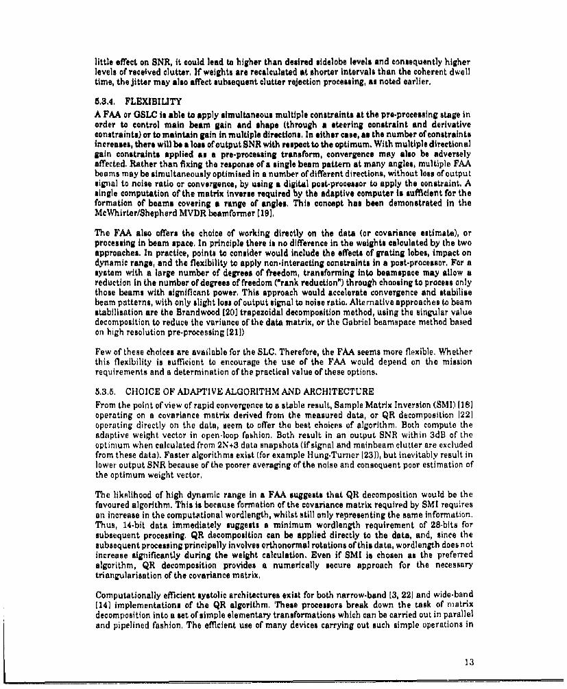
5,3.4, FLEXIBILITYA FAA or GSLC is able to apply simultaneous multiple constraints at the pre-processing stage inorder to control main beam gain and shape (through a steering constraint and derivativeconstraints) or to maintain gain in multiple directions. In either case, as the number of constraintsincreases, there will be a lose of output SNR with respect to the optimum, With multiple directionalpin constraints applied as a pre-processing transform, convergence may also be adverselyaffected. Rather than fixing the response of a single beam pattern at many angles, multiple FAAbeams may be simultaneously optimised in a number of different directions, without loss of outputsignal to noise ratio or convergence, by using a digital post-processor to apply the constraint, Asingle computation of the matrix inverse required by the adaptive computer is sufficient for theformation of beams covering a range of angles, This concept has been demonstrated in theMcWhirter/Shepherd MVDR beamformer (19],
The FAA also offers the choice of working directly on the data (or covariance estimate), orprocessing in beam space, In principle there is no difference in the weights calculated by the twoapproaches. In practice, points to consider would include the effects of grating lobes, impact ondynamic range, and the flexibility to apply non-interacting constraints in a post-processor, For asystem with a large number of degrees of freedom, transforming into beamapace may allow areduction in the number of degrees of freedom ("rank reduction") through choosing to process onlythose beams with significant power, This approach would accelerate convergence and stabilisebeam patterns, with only slight loss of output signal to noise ratio. Alternative approaches to beamstabilisation are the Brandwood [20] trapezoidal decomposition method, using the singular valuedecomposition to reduce the variance of the data matrix, or the Gabriel beamspace method basedon high resolution pre-processing [211)
Few of these choices are available for the SLC, Therefore, the FAA seems more flexible, Whetherthis flexibility is sufficient to encourage the use of the FAA would depend on the missionrequirements and a determination of the practical value of these options,
563.5, CHOICE OF ADAPTIVE ALGORITHM AND ARCHITECTUREFrom the point of view of rapid convergence to a stable result, Sample Matrix Inversion (SMI) [118operating on a covariance matrix derived from the measured data, or QR decomposition 1221operating directly on the data, seem to offer the best choices of algorithm, Both compute theadnptive weight vector in open-loop fashion, Both result in an output SNR within 3dB of theoptimum when calculated from 2N+3 data snapshots (if signal and mainbeam clutter are excludedfrom these data), Faster algorithms exist (for example Hung-Turner [231), but inevitably result inlower output SNR because of the poorer averaging of the noise and consequent poor estimation ofthe optimum weight vector,
The likelihood of high dynamic range in a FAA suggests that QR decomposition would be thefavoured algorithm. This is because formation of the covariance matrix required by SMI requiresan increase in the computational wordlength, whilst still only representing the same information.Thus, 14-bit data immediately suggests a minimum wordlength requirement of 28-bits forsubsequent processing. QR decomposition can be applied directly to the data, and, since thesubsequent processing principally involves orthonormal rotations of this data, wordlength does notincrease significantly during the weight calculation. Even if SMI is chosen as the preferredalgorithm, QR decomposition provides a numerically secure approach for the necessarytriangularisation of the covariance matrix.
Computationally efficient systolic architectures exist for both narrow-band [3, 22] and wide-band[141 implementations of the QR algorithm. These processors break down the task of matrixdecomposition into a set of simple elementary transformations which can be carried out in paralleland pipelined fashion, The efficient use of many devices carrying out such simple operations in
1,3

parallel results in architectures which actually scale in power to match the size of the problem(increasing number of degree& of freedom), Given the rapidly increasing power of standard DSPchips, an alternative approach could be to farm out entire matrix decomposition onto individualmicroprocessors [24]. Each would calculate a weight vector appropriate to a different sample ofdata, Following an initial period of latency, updates could be provided in rapid succession ifnecessary, In future, alternative 64 bit floating point DSP microprocessors, using number theoretictransforms to obtain wordlength-lndependent processing rates may possibly make covariance-domain processing even more viable in this context, With any of these approaches, both on-line andoff-line architectures are possible (10, 25), However, it is likely that the off-line solution withperiodic weight update would be used in practice, since this allows greater control over the updaterate (to match the coherent integration period), and also enables calculations to be carried out ona sub-set of the received samples, This may imply the need for more systolic nodes in order toextract the required weight vectors in parallel, or a corresponding reduction in the achievableweight update rate, The SLC, with its apparent lower dynamic range requirement, may be able tomake use of less numerically sophisticated algorithms and alternative processing architectures,such as in the FLAP processor used for MESAR [26],
A further alternative possible with the FAA would be to use a high resolution algorithm in place ofthe usual adaptive processing t15, 21], (The broad coverage of the main beam of a SBR suggeststhat high resolution may be desirable in any case.) Such an algorithm would provide directestimates of jammer parameters, such as direction of arrival, power and cross-correlation, Theestimated jammer positione output from such an algorithm could be used to form "deterministic"nulls, By this we mean that steering vectors corresponding to estimated directions of jammingsources would be used in place of data in order to construct the appropriate weighting vector, Thiswould also confer stability when processing in the presence of a strong desired signal,Alternatively, if the desired signal is below the noise level as we have assumed, then the weightvector output by the high resolution technique itself may be used to null jamming, It may also bepossible to carry out "high resolution" processing following pulse compression and coherentintegration, using techniques such as IMP (27,281 or PTMF (291, This could provide a way ofhandling the problem of estimating the direction of arrival of the main signal, Beam skew, causedby nulling of main-beam jamming, would no longer be apparent as a problem,
6. SUMMARY
In the context of an imagined space-based phased array radar, we have examined the applicationof three different adaptive nulling schemes, We have shown thitt the design of the "front-end"signal processing (from antenna design through to ADC design and clutter processing) has animpact on the use of an adaptive algorithm. Conversely, the decision to make use of adaptivenulling places constraints and strict. perfornnance requirements on other parts of the system, The"system" clearly cannot be distinguished from the "signal processing", We see, not surprisingly,that the radar must be designed as a whole, taking into account trade-ofts and Interactionsbetween components,
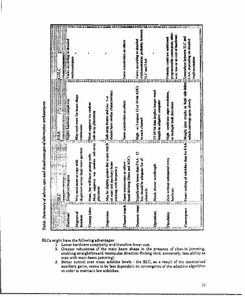
In addition, our review has led to a number of interesting conclusions regarding the suitability ofthe different adaptive nulling architectures to the space-based application. These are summarisedbelow, and are also given in the table.
Fully adaptive arrays would seem to have a number of broad advantages:1. Effective main beam nulling capability, but accompanied with distortion of the un-
norinalised beamshape and lower output SNIR than for sidelobe jamming,2. Greater flexibility through the use of programmable constraints, the ability to
simultaneously make available more than one optimised output, and the option ofcarrying out high resolution processing.
3. Potentially lower sensitivity to aperture dispersion effects,4. All channels (nominally) the same. The FAA sub-array beam patterns will all have
similar frequency sensitivity and are more likely to track as a function of amplitude,time and temperature.
14
aN III411 ii ill IS!
I42I
'~. I J l~ZWh61 I~''~i~
V7 2 ......
1'~ mih hav th olwnNdatgs1.Lwrhadaecopeiy n hreoelwe ot
2. G e t r rbu t e s o h mai n be m s a e in h r s n e o l s -nj m i
3.~ migh t ehave nth o oe r me nib ees-t eS C a euto h o srie
2auGreatry robustnesms tofteai bea lshadpendn in thnepregence of tloeaapine jammingh
in order to maintain low sidelobes,

4. A lower dynamic range is required of the adaptive circuits if powerful jamming entersonly via (attenuated) sidelobes;
5. It is easier to avoid problems with grating lobes the system would not be asked to formnulls in directions equivalent to the constrained main beam.
It is difficult to draw such simplified conclusions about the broad category of "generalised" sidelobecancellers, as these may have a range of features which overlap the two extreme types, and whichdepend on the detail of the particular design, Clearly, those systems which are mathematicallyequivalent to the FAA should have broadly the same advantages and disadvantages (although it isdifficult to see how post-processing constraints would apply). If the system is restricted to sidelobecancellation, then it may be designed to benefit from the lower dynamic range, as with the SLC.
7. REFERENCES[1] G A Shaw, R J McAulay, The application of multichannel signal processing to cluttersuppression for a moving platform radar, ASSP Spectrum Estimation Workshop II, Tampa,Florida, USA, 308.312, (1983).(21 F J Harris. On the use of windows for harmonic analysis with the discrete Fourier transform.Proc IEEE 88, 51.83, (1978).[3] L C Griffiths, C W Jim, An alternative approach to linearly constrained adaptivebeam/forming. IEEE Trans AP.&0, 27.34, (1982),[41 J G McWhirter, T J Shepherd, A systolic array for constrained least squares problems. ProcSPIE in, 80.87, (1986),(51 B van Veen, Systolic preprocessors for linearly constrained beam forming, IEEE Trans ASSP.SUZ(4), 600.604, (1989),(61 R P Flare, Design rules for adaptive arrays, IEEE Trans AES.20(2), 199.202, (1984),[71 E R Billam, D H Harvey, MESAR an advanced experimental phased array radar. ProcRADAR-87 (UEE Conf Publ 281), 37.40, 01987),181 D A Linebarger, I H Sudborough, I G Tollis, A unified approach to design of minimumredundancy arrays, Proc 24th Asilomar Conf., Pacific Grove, November 1990,[9] P Barton, Adaptive antennas, AGARD Lecture Series 151, Microwave Antennas for Avionics,(1987).t101 S C Pohlig, Hybrid adaptive feedback nulting in the presence of channel mismatch, ProcICASSP, 1588.1591, (1988).1111 C R Ward, P J. Hargrave, J G MeWhirter, T J Shepherd. A novel accelerated convergencetechnique for adaptive antenna applications, IEE Proc 6th Int Conf Ant Prop, Warwick, Apr 1989,(121 1 J Gupta, A A Ksienski. Dependence oif adaptive array performance on conventio, nal arraydesign. IEEE Trans AP.-n(4), 549.553, (1982).113] J E Hudson, Adaptive array principles, IEE Press.114] 1 K Proudler, T J Shepherd, J G McWhirter, Computationally efficient QRD.based wide-bandbeamforming, Proc ICASSP 1990,[151 S C Knowles, J G McWhirter, R F Woods, J V McCanny, A bit level systolic architecture forvery high performance fiR filters. Proc ICASSP, 2449-2452, (1989).[16] U Nickel, Angle estimation with adaptive phased array radar under mainbeam jammingconditions, AGARD, October 1990.[17] J G McWhirter. A briefreview of adaptive null steering techniques, Royal Signals and RadarEstablishment Memorandum no 3939, (1986),1181 1 8 Reed, J D Mallet, L E Brennan. Rapid convergence rate in adaptive arrays, IEEE TransAES.j0(6), 853.863, (1974).[19] J G McWhirter, T J Shepherd. Systolic array processor for MVDR beamforming, IEE Proc-F136(2), 7 5.80, (1989),120] D H Brandwood, J D Baker, Stabilisation of adaptive array patterns using signal spaceprojection. IEE Proc 6th Int Conf Ant Prop, Warwick, Apr 1989,1211 W F Gabriel. Using spectral estimation techniques in adaptive processing antenna systems,NRL Report 8920, October 9, 1985.1221 C R Ward, P J Hargrave, J G McWhirter. A novel algorithm and architecture for adaptivedigital beamforming. IEEE Trans AP.34(3), 338-346, (1986).
16

[231 E K L Hung, R M Turner. An adaptwe jammer suppression algorithm for large arrays,McMaster University, (1981),[241 M Wells, MESAR adaptive nulling / digital adaptive architectures, Contribution no.2, lEEColloquium on "Adaptive Antennas", Savoy Place, 8th June, (1990), 1EE Digest No: 1990/098.[25) J G McWhirter. Algorithmic engineering, an emerging discipline, Proc SPIE 1I=Z, Aug 1989,[261 Floating Point Array Processor (Flap), Plessey Research Roke Manor publication 10,032(1987).[27) 1 J Clarke. High discrimination target detection algorithms and estimation of parameters,Underwater Acoustic Data Processing, Y T Chan, Ed,, Kuwer Academic (1989).[28J J L Mather. Performance of the IMP array processing algorithm: first results. Royal Signalsand Radar Establishment Memorandum no 4291, (1989).1291 U Nickel, Angle estimation with adaptive arrays and its relation to super-resolution. lEE Proc-1 L.U(), 77-82, (1987).
17

APPENDIX
DETERMINATION OF SIGNAL-, CLUTTER-, AND JAMMER-TO-NOISE RATIOSAT ANTENNA ELEMENTS
Assume the following radar parameters:
Wavelength X = 26 cmAntenna area A = 28 x 9mBeamwidths 0az = 1.7', 0 el = 0,5'
Number of antenna elements 16384 (i.e. 214)
Peak power P- 100kWDuty ratio = 10%Pulse-repetition frequency i 10kHzAgile bandwidth, Ba - 200MHzSignal bandwidth a 1 MHzTar,-.t cross-section at = 1 - 10 sq. m.
Noise figure F = 3dBLosses L = 10- 13dB + scanning loss where appropriate
h
Height, h = 1000 kmScan angle = 29 - 58'Taking the radius of the earth to be 6400km,
Slant range R = 1172 - 2665 kin,Grazing angle, g = 56. 11.3'.
For SNR and CNR, best and worst cases will be considered in order to obtain maximum andminimum values, By "best" we mean best from SNR point of view, i,e. 29' scan angle, This anglealso produces the highest CNR.
19

(i) SIGNAL TO NOISE RATIO (SNR)PAat
Peak SNR at element per pulse (i.e, before integration) = 16•R 4 LkTIBa
+dB -dB +dB AdB
PA 74 74at 10 0
16n 17 17
R4 243 257L 11 16
kTF 201 201Ba 83 83
*..o .... .... °...
+285 .354 +275 -373
SNR -69dB -98dB
(ii) CLU7I'ER TO NOISE RATIO (CNR)
If the effective cross-section cc of the ground covered by one range cell can be determined, it can besubstituted for at in the above expression to evaluate mainlobe CNR, This is most easily, althoughapproximately, done by first considering the dotted line in the diagram,
The dotted line represent3 approximately the length of Earth's surface illuminated by the beam,projected onto a plane perpendicular to the direction of the beam, It has length R 0e1 , The length of
one range cell and its ambiguities is then R10. x duty ratio. (The effect of beam broadening an Oeldue to scanning of the beam may be disregarded, because scanning loss will cancel it out.) The areaof a range cell is therefore R2Oazoel x duty ratio,
The effective echoing area of each sq, m, of projected area is y, the normalised backscatteringcoefficient, We assume ylies between -10 and .20dB sq. m. per sq. m,, and is constant with grazingangle. The total effective echoing area is therefore
Cc = R20azeel . y, duty ratio. beam-weighting factor,
The beam-weighting factor is to account for the reduction in width of ambiguous range cellstowards the edge of the beam, and also for the reduction in transmit power reaching these cells,
20
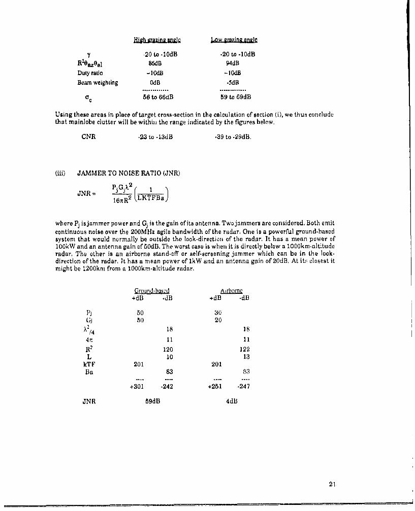
Hkh grarzm~ng w!gLwgznzag
, 20 to -10dB -20 to -10dBR20aZeel 86dB 94dBDuty ratio -104b -10dB
Beam weighting 0dB -5dB
cc 56 to 66dB 59 to 69dB
Using these areas in place of target cross-section in the calculation of section (i), we thus concludethat mainlobe clutter will be withinl the range indicated by the figures below.
CNR -23 to -13dB -39 to .29dB&
(iii) JAMMER TO NOISE RATIO (JNR)
JNRb P= J 2
1NRR2 LKTFBaJ16nR2(
where Pj is jammer power and Gj is the gain of its antenna. Two jammers are considered, Both emitcontinuous noise over the 200MHz agile bandwidth of the radar. One is a powerful ground-basedsystem that would normally be outside the look-direction of the radar, It has a mean power of100kW and an antenna gain of 50dB, The worst case is when it is directly below a 1000km-altituderadar, The other is an airborne stand-off or self-screening jammer which can be in the look.direction of the radar, It has a mean power of 1kW and an antenna gain of 20dB, At its closest itmight be 1200km from a 1000km-altitude radar.
Ground-bascd+dB -dB +dB -dB
Pi 50 30Gj 50 20
X./4 18 18
4rn 11 11
R2 120 122L 10 13
kTF 201 201Ba 83 83
+301 -242 +251 -247
JNR 59dB 4db
21

THIS PAGE IS LEFT BLANX, RNTNTIONALLY

REPORT DOCUMENTATION PAGE DRIC Reference Number (if known) ............................
O verall security classification of she t .................................... U N C LA S S IF IE D ....................................................................................(As far as possible this sheet should contain only unclassified information. If It Is necessary to enter classified information, the field concernedmust be marked to Indicate the classlfication eg (R), (C) or (S).
Originators Reference/Report No. Mont YearMEMO 4410 JANUARY 1991
Originators Name and LocationRSREi St Andrews RoadMalvern, Worcs WR143PS
Monitoring Agency Name end Location
Title
IMPLICATIONS OF ADAPTIVE CANCELLATION ARRAY PROCESSING FORDESIGN OF A SPACE-BASED SURVEILLANCE RADAR
Report Security Classification Title Classification (U, R, C or S)UNCLASSIFIED U
Foreign Language Title (In tho case of translations)
Conferonce Details
Agenc•y Reference ..... .. .. . . ..Contract Number and P~eriod ... ...
Project Number Other References
Pagination and Rief
MATHER, J; FAIRHEAD, A C; WARDEN, M P 21
Abstract
We examinethe systemcdesign issues associatedwilhthe use of adaptive jammer rejection inthe contextof possible specifications for a space-based surveillance radar. We Show that the adaptive nullingrequirements of the system cannot be considered in isolation. Adaptive processing has implications forthe entire system, from design of the antenna array, through to the choice of AD~s and the requirementsof subsequent coherent Integration and detection processing, Three different classes ol adaptiveprocessing architecture are considered: the sldelobe canceller, the fully adaptive array, and thegeneralised sidelobe canceller. These are shown to achieve different trade-offs between Inherentcomplexity, requirements upon the system specification, flexibility and performance.
Abstract Classification (U,R,C or S)
U
Descriptors
Distribution Statement (Enter any limitations on the distribution of the document)
UNLIMITED
S8(48

THIS PAGE IS LEFT BLANK INTENTIONALLY