rpl: dps 005- 006, vintage a, rebel commercial packaged rooftop · rebel® rooftop, dps 005 - 006...
TRANSCRIPT

Replacement Parts List No. 700024200Revision AF 04/2020
DaikinDaikin McQuay
Rebel® Commercial Packaged Rooftop
Cooling and HeatingDPS
005 - 006Vintage A
To find your Daikin Applied parts distributor, call 1-800-377-2787 or visit www.DaikinApplied.com

Rebel® Rooftop, DPS 005 - 006 Vintage A Rev. AF 04/20 RPL 7000242 / Page 2
ContentsParts List Revision History ............................................................................................................................ 4Serial Number Nomenclature ........................................................................................................................ 5Unit Model Nomenclature Complete ......................................................................................................... 6- 9Electrical Legend ..................................................................................................................................... 10, 11Unit Layout .................................................................................................................................................... 12 Refrigeration Section Refrigeration Section Schematics ........................................................................................................... 13 Compressor & Refrigeration Components Diagram ................................................................................ 14 Compressor & Refrigeration Components ......................................................................................... 15, 16 Oil ............................................................................................................................................................ 16 Discharge Tubing Diagrams ..................................................................................................................... 17 Discharge Tubing Components ................................................................................................................ 18 Solenoid Valve Tubing ............................................................................................................................. 19Coil & Condenser Section Coils ......................................................................................................................................................... 20 Outdoor/Condenser Fan .......................................................................................................................... 21Economizer/Return Air Section Economizer/Return Air Diagram & Components ...................................................................................... 22 Sensor Control Panel & California Title 24: Code 30= F .......................................................................... 23 Outside Air Monitor: Code 28= A ............................................................................................................. 24Energy Recovery Section Heat Wheels, Bypass Damper, & Filters ................................................................................................. 25 Heat Wheel Components ........................................................................................................................ 26Supply Air Section Supply Air Fans ....................................................................................................................................... 27 Filters ....................................................................................................................................................... 28Heat Section Gas Heat: Code 06= G Heat Exchanger Assemblies .............................................................................................................. 29 Heat Exchanger Components ............................................................................................................ 30 Electric Heat: Code 06= E ....................................................................................................................... 31 Hot Water Heat: Code 06= W ................................................................................................................... 32Cabinet Components Diagrams ............................................................................................................................................ 33- 35 Common Cabinet Hardware & Gaskets .................................................................................................. 36Controls (9/12 & Earlier) Control Box Diagrams .............................................................................................................................. 37 Control Box Component Label Diagram .................................................................................................. 38 Common Control Box Components ................................................................................................... 39, 40 Inverter Control Panel Components ......................................................................................................... 41 Disconnect Switches and Power Block PB1 ............................................................................................ 42 Transformers, Fuses, & Terminal Blocks ............................................................................................ 43, 44 Motor Protector MMP1 ............................................................................................................................. 45 Motor Protectors MMP10 & MMP51 ......................................................................................................... 46

Rebel® Rooftop, DPS 005 - 006 Vintage A Rev. AF 04/20 RPL 7000242 / Page 3
Contents, ContinuedControls (11/12 & Later) 1
Control Box Diagrams ............................................................................................................................. 47 Main Control Box Component Label Diagram ......................................................................................... 48 Common Main Control Box Components .......................................................................................... 49, 50 Inverter Control Panel Components ........................................................................................................ 51 Disconnect Switches and Power Block PB1 ............................................................................................ 52 Transformers, Fuses, & Terminal Blocks ........................................................................................... 53- 56 Compressor Contactors & Motor Protectors ............................................................................................ 57 Supply & Exhaust Fan Contactors & Motor Protectors ............................................................................ 58Intelligent Equipment ................................................................................................................................... 59
1 For units built 10/12, use the Distributor Tools BOM Search function on the Daikin Parts website or contact Daikin Applied with model and serial number information to ensure that the correct part(s) are identified.

Rebel® Rooftop, DPS 005 - 006 Vintage A Rev. AF 04/20 RPL 7000242 / Page 4
Parts List Revision History Revision Date Description A- R 10/16 Archived Revs. A- R. S 11/16 Page 6, 7: Misc. Code updates. Page 10, 37, 45: Deleted PC7. Not used w/ EC Motors. Page 46: Updated ERW p/ns. Page 51: Rewrote pg. header. Page 52: Updated SAF/EXH contactors & motor protectors. Rewrote pg. header. T 01/17 Page 14, 17: Changed Trans. Cable p/n from “074667502” to “300058165”. Page 36, 46: Added GFR CT p/n. Page 45: Added 1/17 & Later Duct Mtd. SHS1 p/n. U 06/17 Page 21: Updated Ref. # H750 p/ns. V 07/17 Page 32: Updated the dwg. W 09/17 Page 21: Corrected in/out effect dates for Ref. # H750. Y 10/17 Page 29: Added coding to LP Conv. Kit & footnote # 1. Z 01/18 Page 7: Updated Code 24 HW coil coding. Page 14: Added coding to Ref. # T620. Page 19: Updated coding for uncoated coils & Evap. Coil dwg. Added Overflow Sw. Ref # E060 info. Page 29: Rewrote footnote # 1. Added cable p/ns. Page 31: Updated coil coding. Page 46: Changed PVM p/n from “300051461” to “193599301”, Socket from “300051462” to “193599401”. Page 50: Added 4/14 & Later T2 p/ns. Added footnote # 3. AA 02/18 Page 6: Added footnote # 1. Page 7, 8: Misc. updates. Page 9 (NEW): Added pg. for additional TOC. Repaginated form & updated the TOC. Page 9 (OLD) 10 (NEW): Added “CHK” info. Misc. description updates. Page 10 (OLD) 11 (NEW): Added “SPD/SPD1” info. Page 33 (OLD) 34 (NEW): Added footnote. Page 43 (OLD) 44 (NEW): Updated dwgs. & bub #s. Added footnote. Page 46 (OLD) 47 (NEW): Added CHK & SPD p/ns. Page 47 (OLD) 48 (NEW): Misc. updates. AB 03/18 Page 10: Added “DMS1, 2” info. Page 23: Added DMS1, 2 coding. Page 41: Corrected T4 qty. Page 51: Added 2/15 & Later T4 p/n. Rewrote footnotes. AC 06/18 Page 30: Changed Ref # HTR020 p/n “300049293” to “300056420”. Added footnote # 2. Page 54: Rewrote Notes, rewrote pg. header, & updated the dwg. AD 08/18 Page 15: Added schematic designator to Ref # T207. Page 18: Added schematic designator to Ref # T240. Page 54: Rewrote pg. header & updated the TOC. AE 01/19 Various: Rewrote note re. contacting DAA. Changed “HGRH” to “MHGR”. Deleted 575V info. Page 10: Misc. updates. Page 20: Rewrote Indoor Coil table header. Page 21: Updated coding. Deleted 575V info. Updated C720 info. Added footnote. Page 22: Updated dwg. & table. Page 25: Updated the table. Page 26: Updated the dwg. Added date cutoffs. Rewrote footnotes. Page 28: Updated the filter description. Page 32: Updated the coil p/ns. Added footnote # 1. Page 41, 53: Updated qtys. Added footnote as needed. Page 36, 46: Added MCB Battery p/n 193409001. Page 47: Added 7/18 & Later MMP60 p/n. Page 50, 51: Updated/corrected p/ns. Added/rewrote footnotes as needed. Page 53, 54 (NEW): Added pgs. for additional components. Repaginated the form & updated the TOC. AF 04/20 Page 6- 8: Updated coding. Page 25: Updated Ref. # J700 p/ns. Rewrote Ref. # J700 header. Page 28: Added dwg., Ref. # F720 info., dwg. notes, & footnote # 1. Page 33- 35 (NEW): Added pgs. for additional Cabinet dwgs. Repaginated the form & updated the TOC.
Daikin Applied, 13600 Industrial Park Blvd., P.O. Box 1551, Minneapolis, MN 55440 (763) 553-5330

Rebel® Rooftop, DPS 005 - 006 Vintage A Rev. AF 04/20 RPL 7000242 / Page 5
Plant IdentificationFBO = Faribault, MN
Year of Manufacture
12 = 201213 = 2013 14 = 2014 15 = 2015
etc.
U= UnitSerial Number (Build sequence)
Month of Manufacture01= January02= February03= March04= April05= May06= June 07= July08= August09= September10= October11= November12= December
Serial Number Nomenclature
FBO U 12 05 04800

Rebel® Rooftop, DPS 005 - 006 Vintage A Rev. AF 04/20 RPL 7000242 / Page 6
Unit Model Nomenclature CompleteDPS 005 A H C G 4D C H A R 1DY V A 4 S S M B Y GM 01 02 03 04 05 06 07 08 09 10 11 12 13 14 15 16 17 18 19 20 21 Code
14DY 1250 012SM 1 H 1 Y Y Y A YYY YY Y EM 12DY 22 23 24 25 26 27 28 29 30 31 32 33 34 35 36
AAA Y Y A A A 03800 073 541 02400 073 Y 37 38 39 40 41 42 43 44 45 46 47 48
01 DPS= Daikin Applied Packaged System
02 Unit Size 005= 5 Ton 006= 6 Ton
03 Vintage A= Vintage A
04 Cooling Efficiency H= High (exceeds ASHRAE 92)
05 Unit Style C= Cooling H= Heat Pump M= Microchannel
06 Auxiliary Heat G= Natural Gas E= Electric W= Water Y= None
07 Voltage / Power Connection Digit 1: Line Voltage 2= 208 Volt Power Supply 3= 230 Volt Power Supply 4= 460 Volt Power Supply Digit 2: Connection Type P= Power Block R= Dual Power Block E= Power Block w/ 10KAIC SCCR/65 opt. SCCR D= Non-Fused Disconnect Switch N= Non-Fused Disconnect w/ 10KAIC SCCR F= Fused Disconnect w/ high SCCR C= Dual Power Supply w/ Disconnect
08 Application C= Constant Volume V= Variable Volume Standard Discharge Control B= Building Pressure Supply Fan Control D= 100% OA DAT Control W= Variable Volume Space Control 09 Airflow Pattern V= Vertical Discharge and Return H= Horizontal Discharge and Return A= Vertical Discharge and Horizontal Return B= Horizontal Discharge and Vertical Return C= Vertical Discharge and No Return D= Horizontal Discharge and No Return
10 Controls A= MicroTech III C= Refrigerant Only Controller 11 Communication Cards R= Factory Installed BACnet/IP card S= Factory Installed LON card T= Factory Installed BACnet/MSTP card C= Factory Installed BACnet/MSTP card (Contractor configurable) A= Factory Installed Hybrid VRV Communication card I= Field Installed BACnet/IP card L= Field Installed LON card M= Field Installed BACnet/MSTP card Y= None
12 Outside Air Digit 1: Type 1= 0- 100% Economizer 3= 0- 30% Outside Air A= 100% Outside Air Damper, No Return Y= 100% Return Digit 2: Control D= Dry Bulb C= Comparative Enthalpy Y= None Digit 3: Control Over Ride C= CO2 Over Ride Y= None
13 Exhaust Air R= Barometric Relief V= Powered, Modulating Y= None
14 Filters A= 2” MERV 8 B= 4” MERV 14, with 2” MERV 8 Pre-filter Y= None
15 DX Coil 4= 4 Row 16 Drain Pan S= Stainless Steel T= Stainless Steel w/ Overflow Switch
17 Liners G= Galvanized
1 In mid 2017 the code structure was changed from a 48 code index to a longer more detailed format. A sample 48 Code version is shown above.

Rebel® Rooftop, DPS 005 - 006 Vintage A Rev. AF 04/20 RPL 7000242 / Page 7
Unit Model Nomenclature Complete, Continued18 Hot Gas Reheat (MHGR) M= Modulating Hot Gas Reheat Y= None
19 Coil Options B= All Coils Coated C= Outdoor Coil Coated E= Indoor Coils Coated Y= None
20 Intelligent Equipment A= Intelligent Equipment L= Intelligent Equipment Lite Y= None
21 Supply Fan Motor Digit 1: Motor Size E= 1.3HP, 1.0kW G= 2.3HP, 1.7kW H= 4.0HP, 3.0kW K= 8.0HP, 6.0kW Digit 2: Motor Type M= Electronic Commutator Motor (ECM)
22 Indoor / Supply Fan Digits 1- 2: Fan Diameter 12= 12” (310 mm) 14= 14” (355 mm) 16= 16” (400 mm) Digit 3: Drive Type D= Direct Drive Digit 4: Isolation Type Y= None
23 Indoor / Supply Fan RPM Digits 1- 4: Final Drive RPM (Eg. 1250= 1250 RPM)
24 Gas Heat Digits 1- 3: Capacity (MBH Input) 008= 80MBH 012= 120MBH 016= 160MBH YYY= None Digit 4: Furnace Material G= Aluminized Steel S= Stainless Steel B= SS- 100° Temp. Rise, 81% eff. T= Stainless Steel- High Temperature Rise Y= None Digit 5: Control 2= 2 Stage M= Modulating 5:1 Y= None
24 Electric Heat Digits 1- 3: Capacity 006= 6kW 012= 12kW 018= 18kW 030= 30kW YYY= None Digit 4: No Requirement, not a DPS Code Y= None Digit 5: Control 2= 2 Stages 4= 4 Stages S= SCR Y= None
24 Hot Water Heating Coil Digits 1- 3: Water Coil W**= Water Coil (Digits 2, 3 non-critical) YYY= None Digit 4: Number of Coil Rows 1= 1 Row 2= 2 Rows 3= 3 Rows Y= None Digit 5: Control / Valve Package Y= None 2= 2 Way 3= 3 Way
24 Field Installed Heat FFFFY= Field Installed Heat YYYYY= None
25 Low Ambient Control 1= Mechanical Cooling to 23 Degrees F
26 Electrical Options F= Factory Wired GFI Receptacle G= Field Wired GFI Receptacle H= Factory Wired GFI Receptacle w/ Phase Voltage Monitor (PVM) J= Field Wired GFI Receptacle w/ Phase Voltage Monitor (PVM) K= Phase Voltage Monitor (PVM) only Y= None
27 Smoke Detector 1= Return Air Smoke Detector Y= None
28 Outside Air Monitoring A= Ebtron OA Monitoring Y= None
29 UV Lights Y= None
30 California Title 24 F= Economizer with Fault Detection/Diagnosis (FDD) Y= None

Rebel® Rooftop, DPS 005 - 006 Vintage A Rev. AF 04/20 RPL 7000242 / Page 8
Unit Model Nomenclature Complete, Continued
31 Compressor Isolation Valves A= Suction & Discharge Isolation Valves Y= None
32 Heat/Energy Wheel Digit 1: Wheel Airflow L= Standard Airflow H= High Airflow Y= None Digit 2: Bypass Damper B= Bypass Damper Y= None Digit 3: Wheel Options P= Energy Wheel w/ Purge Option F= Field Supplied Wheel S= Sensible Wheel w/ Purge Option K= Monolithic Wheel with Purge Y= None
33 Heat/Energy Wheel Control Digit 1: Defrost Options V= Modulating Wheel Frost Prevention F= Staged Wheel Frost Prevention C= On/Off Defrost Control Y= None Digit 2: Wheel Effectiveness Control A= Wheel Effectiveness Control Y= None
34 Heat/Energy Wheel Filtration A= Standard Outside Air Side only B= Outside & Return Air Side Y= None
35 Exhaust Fan Motor Digit 1: Motor Size (Horsepower) E= 1.3HP, 1.0kW G= 2.3HP, 1.7kW Y= None Digit 2: Motor Type M= Electronic Commutator Motor (ECM) Y= None
36 Exhaust Fan Digits 1- 2: Fan Diameter 12= 12” (310 mm) 14= 14” (355 mm) Digit 3: Drive Type D= Direct Drive Digit 4: Isolation Type Y= None
37 Unit Approvals Digit 1: ETL Listing A= ETL Y= None Digit 2: Gas Heat Approvals A= ETL B= ETL High Altitude Y= None Digit 3: AHRI Certified A= AHRI Certified-90.1 2007 B= AHRI Certified-90.1 2010 C= AHRI Certified-90.1 2013 D= AHRI Certified-90.1 2016 Y= Non AHRI compliant
38 Outdoor Coil Options V= Vandal Guards Y= None
39 Electronic Expansion Valves Y= Unspecified D= Danfoss S= Saginomiya
40 Parts Warranty A= Standard C= Additional 1 Year D= Additional 2 Years E= Additional 3 Years F= Additional 4 Years Z= Special
41 Compressor Warranty A= Standard 1 Year Q= Additional 4 Years
42 Heat Exchanger Warranty A= Standard 1 Year R= Additional 9 Years Y= None
43 SA Fan CFM 00000= CFM From Selection Program
44 SA Fan BHP 000= BHP From Selection Program (Eg. 073 = 7.3)
45 Discharge Air Temperature 000= DAT From Selection Program (Eg. 541 = 54.1° F)
46 EAF CFM 00000= CFM From Selection Program
47 EAF BHP 000= BHP From Selection Program (Eg. 073 = 7.3)
48 Miscellaneous X= Special Y= None
Rebel® Rooftop, DPS 005 - 006 Vintage A Rev. AF 04/20 RPL 7000242 / Page 9
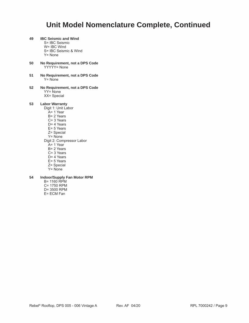
49 IBC Seismic and Wind S= IBC Seismic W= IBC Wind S= IBC Seismic & Wind Y= None
50 No Requirement, not a DPS Code YYYYY= None
51 No Requirement, not a DPS Code Y= None
52 No Requirement, not a DPS Code YY= None XX= Special
53 Labor Warranty Digit 1: Unit Labor A= 1 Year B= 2 Years C= 3 Years D= 4 Years E= 5 Years Z= Special Y= None Digit 2: Compressor Labor A= 1 Year B= 2 Years C= 3 Years D= 4 Years E= 5 Years Z= Special Y= None
54 Indoor/Supply Fan Motor RPM B= 1160 RPM C= 1750 RPM D= 3500 RPM E= ECM Fan
Unit Model Nomenclature Complete, Continued

Rebel® Rooftop, DPS 005 - 006 Vintage A Rev. AF 04/20 RPL 7000242 / Page 10
Electrical Legend
Schematic Sym. Description 4WV Four Way Valve, Heat Pump (Code 05= H) A4P Compressor #1 Inverter Control Board, Primary A4PF Compressor #1 Inverter Electrical Noise Filter A5P Outdoor Fan #1 Inverter Control Board, Secondary A5P+ Outdoor Fan #2 Inverter A5PF Outdoor Fan Electrical Noise Filter ACT12 Actuator Motor, Energy Recovery Wheel ACT3 Actuator Motor, Economizer AHL Auxiliary High Limit BNIP BACnet/IP Communication Module BNMS BACnet/MSTP Communication Module CCH Crankcase Heater CHK/CHK1 Power Filter, Interface Board (IFB) CHV1 Valve, Condenser Coil DAT Temperature Sensor, Discharge Air DFT Defrost Temperature Sensor DHL Duct Hi-limit, Switch DKND3 D3 Gateway VRV Communication Card DMS1, 2 Switches, California Title 24 Fault Detection and Diagnosis (FDD) DRT1 Temperature Sensor, Discharge Refrigerant DS1 Disconnect Switch, Unit Power DS6 Disconnect Switch, Powered GFCI Receptacle DSI 5:1 Modulating Direct Spark Ignition Control EVB Expansion Valve Board EVBF Expansion Valve Board Electrical Noise Filter EVI Indoor Expansion Valve EVO Outdoor Expansion Valve EXPB, D Controller Extension Modules F1A, B Fuses, Control Circuit Transformer (T1), Primary F1C, D Fuses, Control Circuit Transformer (T1), Secondary F4A- C Fuses, Control Circuit Transformer (T4), Primary F6C Fuse, Powered GFCI Transformer (T6), Secondary GFR/GFR1 Board, Ground Fault Relay HEAT1 Heater Module HL Hi-Limit Switch, Gas Heat HP1 Hi-Pressure Switch, Refrigeration Circuit IFB Interface Board IFBF Interface Board Electrical Noise Filter IRT Temperature Sensor, Indoor Refrigerant LCT Temperature Sensor, Leaving Coil LNWK LON DAC Communication Card LR1 Compressor Line Reactor M1F Compressor #1 Electrical Noise Filter MCB Main Control Board MJ Mechanical Jumper MMP1 Manual Motor Protector, A4P Board MMP10 Manual Motor Protector, Supply Fan MMP51 Manual Motor Protector, Exhaust Fan MMP60 Manual Motor Protector, Energy Recovery Wheel OAE Enthalpy Sensor, Outside Air

Rebel® Rooftop, DPS 005 - 006 Vintage A Rev. AF 04/20 RPL 7000242 / Page 11
Electrical Legend
OAER Relay, Outside Air Enthalpy OAM Ebtron Outside Air Monitor OAT Temperature Sensor, Outside Air OF1F Outdoor Fan Electrical Noise Filter 1 OF2F Outdoor Fan Electrical Noise Filter 2 ORT Temperature Sensor, Outdoor Refrigerant PB1 Power Block, Power Distribution PB1F Power Block Electrical Noise Filter PC5 Pressure Control, Dirty Filter Switch PTD Pressure Sensor, Discharge Refrigerant PTS Pressure Sensor, Suction Refrigerant PVM1 Phase Voltage Monitor R63 Relay, Duct High Limit Switch RAE Enthalpy Sensor, Return Air RAT Temperature Sensor, Return Air R-CCH1 Relay, Crankcase Heater REC1 Receptacle, GFCI RHB1 Reheat Board, Hot Gas (MHGR) R-HP1 High Pressure Compressor 1 Relay RHV1 Valve, Reheat Coil SD1 Smoke Detector, Supply Air SHS1 Space Humidity Sensor SPD/SPD1 Surge Protector/Absorber, 115V SPS1 Static Pressure Sensor, Duct SPS2 Static Pressure Sensor, Building SRT Temperature Sensor, Suction Refrigerant SVB Solenoid Valve, Refrigerant Bypass SVR Solenoid Valve, Refrigerant Receiver T1 Transformer, Main Control T12 575/460V Primary Power Transformer T1F Main Transformer Electrical Noise Filter T2A, B Transformers, Control Input (115/24VAC) T4 Transformer, Inverter Boards T6 Transformer, Powered GFCI Receptacle (Line/115VAC) T7 Transformer, Reheat Control Board (115/24VAC) TB1 Terminal Block, Internal Power Distribution TB2 Terminal Block, Field -24V TB8 Terminal Block, Internal Signal Distribution VBC 5:1 Modulating Variable Burner Control VFD60 Variable Frequency Drive, Energy Recovery Wheel ZNT1 Zone Temperature Sensor (field installed)
Schematic Sym. Description

Rebel® Rooftop, DPS 005 - 006 Vintage A Rev. AF 04/20 RPL 7000242 / Page 12
Unit Layout 1
Indoor Coil & Filter Section
Control Box
Supply Fan
Outdoor/Condenser Fan
Gas Outside Air Hood
Economizer
Return Air Damper
Exhaust/Backdraft Damper
Inverter Control Panel
1 Shown above is a typical 6 ton Gas Heat (Code 06= G) unit equipped with a 100% Economizer (Code 12= 1**) and no Energy Recovery [Heat Wheel] option (Code 32= YYY). This picture is to be used for reference only as Components and Component layout differ depending upon unit options selected.

Rebel® Rooftop, DPS 005 - 006 Vintage A Rev. AF 04/20 RPL 7000242 / Page 13
Refrigeration SectionRefrigeration Section Schematics
Cooling Only Unit (Code 05= C)
Heat Pump Unit (Code 05= H)
Schem. Sym. Description EVI Indoor Coil Electronic Expansion Valve EVO Outdoor Coil Electronic Expansion Valve CV Check Valve REC Refrigerant Receiver IDF Indoor Fan ODF Outdoor Fan COMP1 Inverter Compressor COMP2 Fixed speed Compressor SVR Bypass Solenoid Valve RHV Reheat Step Valve SVB Receiver Solenoid Valve CHV Condenser Step Valve

Rebel® Rooftop, DPS 005 - 006 Vintage A Rev. AF 04/20 RPL 7000242 / Page 14
Refrigeration SectionCompressor & Refrigeration Components Diagram
T825
T830
T800
T801
T820T815
T810
See Discharge Tubing Section
T320
See Solenoid Valve Tubing Section
T595T590
T575T580
U602
U601T500
Heat Pump (Code 05= H) w/ MHGR (Code 18= M)
Shown
T620
T410 T445
T450
T455T207
T545
U602U603
U601
Piping detail shown w/ optional Compressor Isolation Valve
(Code 31= A)
U602
U601
T500
T502

Rebel® Rooftop, DPS 005 - 006 Vintage A Rev. AF 04/20 RPL 7000242 / Page 15
Refrigeration SectionCompressor & Refrigeration Components
Ref. # Description Unit Size Part Number 005 006
T207 Valve, MHGR (CHV1) (Code 18= M) 1 1 910142032
T320 Filter, Refrigerant 1 1 910101220
T410 Filter, Refrigerant 1 1 910118879
T445 Filter, Refrigerant (Code 05= H) 1 1 910118879
T450 Valve, Expansion (EVO) (Code 05= H) 1 1 910125722
T455 Motor, Expansion Valve (EVO) (Code 05= H) 1 1 910118758
T500 Transducer, Low Pressure (PTS) 1 1 910153379
N/S Cable, Transducer, Low Pressure (PTS) 1 1 300058165
T502 Valve, Ball, .75” ODS 1 1 910123990
T545 Switch, High Pressure (HP3) 1 1 910130318
T575 Filter, Refrigerant (Code 05= C) 1 1 910118879 Filter, Refrigerant (Code 05= H) 1 1 910101221
T580 Filter, Refrigerant (Code 05= H) 1 1 910118879
T590 Valve, Expansion (EVI) (Code 05= C, M) 1 1 910121127 Valve, Expansion (EVI) (Code 05= H) 1 1 910118756
T595 Motor, Expansion Valve (EVI) 1 1 910118758 T620 Valve, Check (Code 05= C, M) 1 1 910118731
T800 Inverter Compressor 208/230V (Code 07= 2*, 3*) 1 1 910117080 460V (Code 07= 4*) 1 1 910117076
T801 Crankcase Heater, Inverter Compressor 1 1 910118743
T810 Grommet, Compressor 3 3 910031401
T815 Screw, Tap 3 3 113161501
T820 Flat Washer, .312 nom 3 3 041542301N/S= Not shown on diagram.

Rebel® Rooftop, DPS 005 - 006 Vintage A Rev. AF 04/20 RPL 7000242 / Page 16
Refrigeration SectionCompressor & Refrigeration Components & Oil, Continued
T825 Oil Separator 1 1 910119040
T830 Receiver 1 1 910118671
U601 Valve, Schrader 3 2 3 2 071100801
U602 Core, Schrader Valve 3 2 3 2 026541100
N/S Rubber Cushion, Capillary Tubes 1 3 1 3 910130310 N/S Shock Absorber, Capillary Tubes 1 3 1 3 910130317
N/S High Temperature Zip Tie, Capillary Tubes 3 3 3 3 910130283N/S= Not Shown on diagram. 1 Quantity of 0pc. for Cooling Only units (Code 05= C). Quantity of 1pc. for Heat Pump units (Code 05= H). 2 Total quantity required in the applicable section. Not all instances are shown in the accompanying diagram.3 Included in Capillary Tube Protection Kit 300050184. The Capillary Tube Protection Kit includes all listed parts and
Installation Instructions.
Ref. # Description Unit Size Part Number 005 006
Oil Container Size Part Number Oil, PVE Quart 300051200 Oil, PVE Gallon 300051199
Compressor & Refrigeration Components, Continued
Oil

Rebel® Rooftop, DPS 005 - 006 Vintage A Rev. AF 04/20 RPL 7000242 / Page 17
Refrigeration Section Discharge Tubing Diagrams
T250T251
T255
U602
U601 U602U603
U601
T295
T290
Heat Pump (Code 05= H) w/ MHGR (Code 18= M) &
Compressor Isolation Valves (Code 31= A)Shown
Cooling Only (Code 05= C) w/ MHGR (Code 18= M) &
Compressor Isolation Valves (Code 31= A)Shown
T292
T240
Cooling Only (Code 05= C) w/ MHGR (Code 18= M) w/o
Compressor Isolation Valves (Code 31= Y)Shown
T295
T290
U602U601
U603
U602
U601T296

Rebel® Rooftop, DPS 005 - 006 Vintage A Rev. AF 04/20 RPL 7000242 / Page 18
Hot Gas Reheat Valve (Code 18= M) T240 Valve (RHV1) (Code 05= H) 1 1 910121113 Valve (RHV1) (Code 05= C, M) 1 1 910120916
T250 Valve, 4 Way (Code 05= H) 1 1 910118735
T251 Solenoid, 4 Way Valve, 24VAC (Code 05= H) 1 1 106694207
T255 Transducer, High Pressure (PTD) (Code 05= H) 1 1 910153045
N/S Cable, Transducer, High Pressure (PTD) 1 1 300058165
T290 Filter, Refrigerant 1 1 910101221
T292 Valve, Ball, .50” ODS (Code 31= A) 1 1 910123991
T295 Valve, Check 1 1 910118731
T296 Transducer, High Pressure (PTD) (Code 05= C) 1 1 910153045
U601 Valve, Schrader 4 4 071100801
U602 Core, Schrader Valve 4 4 026541100
U603 Cap, Schrader Valve 3 3 032943500
Refrigeration Section Discharge Tubing Components
Ref. # Description Unit Size Part Number 005 006
N/S= Not Shown on diagram.

Rebel® Rooftop, DPS 005 - 006 Vintage A Rev. AF 04/20 RPL 7000242 / Page 19
Refrigeration Section Solenoid Valve Tubing
T380
T360
T375T375
T360T380
Ref. # Description Part Number Qty.
T360 Filter, Refrigerant (Code 05= C) 910101220 1 Filter, Refrigerant (Code 05= H) 910101220 2
T375 Valve Body, Solenoid (SVB) (Code 05= C) 910118733 1 Valve, Body Solenoid (SVB, SVR) (Code 05= H) 910118733 2
T380 Valve Coil, Solenoid, 24VAC (Code 05= C) 910118762 1 Valve Coil, Solenoid, 24VAC (Code 05= H) 910118762 2
Heat Pump (Code 05= H) Shown

Rebel® Rooftop, DPS 005 - 006 Vintage A Rev. AF 04/20 RPL 7000242 / Page 20
Coil & Condenser Section Coils
Outdoor/Condenser Coils
Indoor/Evaporator & Hot Gas Reheat Coils
Ref. # Description Unit Size Part Number 005 006
Uncoated Outdoor Coil (Code 19= Y, E) C001 Coil, Outdoor, Cooling Only (Code 05= C) 1 1 910129443 Coil, Outdoor, Heat Pump (Code 05= H) 1 1 910124536
Coated Outdoor Coil (Code 19= B, C) C001 Coil, Outdoor, Cooling Only (Code 05= C) 1 1 910129467 Coil, Outdoor, Heat Pump (Code 05= H) 1 1 910129466
C800 Guard, Outdoor Coil, Front (Code 38= V) 1 1 910125999 C810 Guard, Outdoor Coil, Side (Code 38= V) 2 2 910126813
Ref. # Description Unit Size Part Number 005 006
Uncoated Indoor Coil (Code 19= Y, C) E001 4 Row Coil, 30.00 x 29.00” 6/13 & Earlier 1 1 1 910115387 4 Row Coil, 30.00 x 29.00” 9/13 & Later 1 1 1 910144022
Coated Indoor Coil (Code 19= B, E) E001 4 Row Coil, 30.00 x 29.00” 1 1 910145113
Uncoated MHGR Coil (Code 19= Y, C) E501 Coil, MHGR (Code 18=M) 1 1 910120659
Coated MHGR Coil (Code 19= B, E) E501 Coil, MHGR (Code 18=M) 1 1 910126871
E060 Condensate Overflow Switch (Code 16= T) 1 1 910167001
C001
C800
C810
C810
1 For units built between 7/13 & 8/13 use the Distributor Tools BOM Search function on the Daikin Parts website or contact Daikin Applied with model and serial number information to ensure that the correct part(s) are identified.
E501E001
E060

Rebel® Rooftop, DPS 005 - 006 Vintage A Rev. AF 04/20 RPL 7000242 / Page 21
Coil & Condenser SectionOutdoor/Condenser Fan
C730 C720
C710
C340
Ref. # Description Part Number Qty.
C340 Panel, Top, Fan Deck 910123602 1
C700 Motor, Fan 208/230V (Code 07= 2*, 3*) 910118746 1 460V (Code 07= 4*) 113170101 1
C710 Blade, Fan 113170001 1
C720 Housing, Fan Bell, 2 pc. 1 910134338 2
C730 Guard, Fan 404015501 1
C740 Cap, Motor Shaft 910118749 1
U001 Screw, 10-16 x 1/2” 059983001 13
U004 Screw, 1/4-20 x 3/4” 112038301 8
C700C740
U001
U004
U004
U001
1 The original one pc. Fan Bell Housing is obsolete and no longer available. This two pc. assembly is a drop in replacement.

Rebel® Rooftop, DPS 005 - 006 Vintage A Rev. AF 04/20 RPL 7000242 / Page 22
Economizer/Return Air SectionEconomizer/Return Air Diagram & Components
Ref. # Description Part Number Qty.
Exhaust Fan, Direct Drive 1 (Code 36= **DY AND Code 13= V) H700 208/230V (Code 07= 2*, 3*) 12” Fan (310mm) (Code 36= 12DY) 910113351 1 1 14” Fan (355mm) (Code 36= 14DY) 910113352 1 1 460V (Code 07= 4*) 12” Fan (310mm) (Code 36= 12DY) 910113348 1 1 14” Fan (355mm) (Code 36= 14DY) 910113350 1 1
H750 Damper, Return 0- 100% Economizer (Code 12= 1**) W/O Heat Wheel 4/13 & Earlier (Code 32= YYY ) 910117473 1 W/ Heat Wheel 4/13 & Earlier (Code 32 CANNOT = YYY ) 910134554 1 ALL 5/13 thru 1/15 910134554 1 ALL 2/15 & Later 404153101 1 0- 30% OR 100% Outside Air (Code 12= 3**, A**) All 12/14 & Earlier 910119571 1 All 1/15 & Later 404166201 1
H840 Actuator, Return Damper (Code 12= 1**, 3**, A**) 113139601 1
H760 Damper, Exhaust/Backdraft (Code 12= 1**) 910120405 1
H800 Filter, Mist Eliminator 910118553 2
H850 Sensor, Enthalpy (OAE) (Code 12= *C*, *E*) 113103601 1N/S= Not shown on diagram.1 Direct Drive Exhaust Fans (Code 36= **DY) are available as an assembly ONLY. Individual Direct Drive Exhaust
Fan components including Fan Wheels, Electronic Commutator Motors (ECMs), etc. CANNOT BE REPLACED INDIVIDUALLY.
H700
H750
H760
H840H800
H850
Unit w/ Heat/Energy Recovery Wheel (Code 32= L**, H**)
Shown

Rebel® Rooftop, DPS 005 - 006 Vintage A Rev. AF 04/20 RPL 7000242 / Page 23
Economizer/Return Air SectionSensor Control Panel & California Title 24: Code 30= F
Ref. # Description Part Number Qty.
H235 Switch, California Title 24 (DMS1, 2) (Code 30= F) 033696300 2
H320 Electrical Box, Smoke Detector 020950800 1
H330 Smoke Detector (SD1) (Code 27= 1) 113126601 1
H340 Enthalpy Transmitter (RAE) (Code 12= 1C*) 113103701 1
H320
H330
H340
H235

Rebel® Rooftop, DPS 005 - 006 Vintage A Rev. AF 04/20 RPL 7000242 / Page 24
Economizer/Return Air SectionOutside Air Monitor: Code 28= A
H290
Return Section w/ Economizer (Code 12= 1**) Shown
H865
H290
H860
Ref. # Description Part Number Qty.
H290 Bracket, Outside Air Probe 910143763 2
H860 Probe, Ebtron Outside Air Monitor 910143762 1
H865 Transmitter, Ebtron Outside Air Monitor (OAM) 910143761 1

Rebel® Rooftop, DPS 005 - 006 Vintage A Rev. AF 04/20 RPL 7000242 / Page 25
Energy Recovery SectionHeat Wheels, Bypass Damper, & Filters
J750
J800
J700
J750AWith Bypass Damper (Code 32= *B*) Shown
Ref. # Description Part Number Qty.
Energy Recovery Wheel, Complete Assy. 6/18 & Earlier J700 W/ Bypass Damper & Purge (Code 32= LBP) 910131827 1 W/ Bypass Damper, Sensible Wheel, Purge (Code 32= LBS) 910132174 1 W/O Bypass Damper & Purge (Code 32= LYP) 910131827 1 W/O Bypass Damper, Sensible Wheel, Purge (Code 32= LYS) 910132174 1 W/O Bypass Damper & Purge (Code 32= HYP) 910131827 1 W/O Bypass Damper, Sensible Wheel, Purge (Code 32= HYS) 910132174 1 7/18 & Later, 115V (ALL) 910142319 1
J700 ALL (Code 32= **K) 243310201 1
J750 Damper, Bypass (Code 12= 1**) 910131935 1
J750A Actuator, Bypass Damper (Code 12= 1**) 113145001 1
J800 Filters 2 x 16 x 16” 910117429 1
1 Quantity is 4pc. per UNIT if Code 12= 3**, A**. Quantity is 2pc. per UNIT if Code 12= 1**.
Rebel® Rooftop, DPS 005 - 006 Vintage A Rev. AF 04/20 RPL 7000242 / Page 26
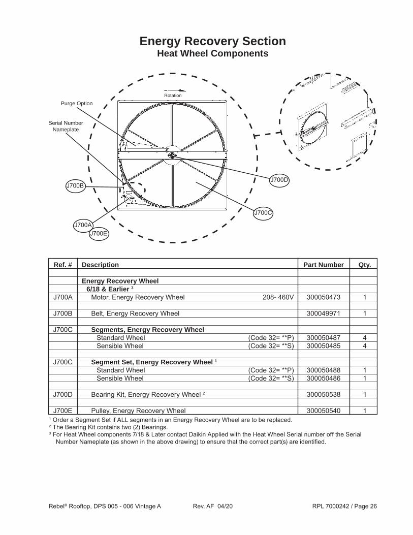
Energy Recovery SectionHeat Wheel Components
Rotation
Purge Option
J700B
J700C
J700A
J700D
J700E
Serial Number Nameplate
Ref. # Description Part Number Qty.
Energy Recovery Wheel 6/18 & Earlier 3
J700A Motor, Energy Recovery Wheel 208- 460V 300050473 1
J700B Belt, Energy Recovery Wheel 300049971 1
J700C Segments, Energy Recovery Wheel Standard Wheel (Code 32= **P) 300050487 4 Sensible Wheel (Code 32= **S) 300050485 4
J700C Segment Set, Energy Recovery Wheel 1 Standard Wheel (Code 32= **P) 300050488 1 Sensible Wheel (Code 32= **S) 300050486 1
J700D Bearing Kit, Energy Recovery Wheel 2 300050538 1
J700E Pulley, Energy Recovery Wheel 300050540 11 Order a Segment Set if ALL segments in an Energy Recovery Wheel are to be replaced.2 The Bearing Kit contains two (2) Bearings.3 For Heat Wheel components 7/18 & Later contact Daikin Applied with the Heat Wheel Serial number off the Serial
Number Nameplate (as shown in the above drawing) to ensure that the correct part(s) are identified.

Rebel® Rooftop, DPS 005 - 006 Vintage A Rev. AF 04/20 RPL 7000242 / Page 27
Supply Air SectionSupply Air Fans 1
Ref. # Description Part Number Qty.
Fan Assembly, Supply Air 1 (Code 22= **DY) D700 208/230V (Code 07= 2*, 3*) 12” Fan (310mm) (Code 22= 12DY) 910113351 1 1 14” Fan (355mm) (Code 22= 14DY) 910113352 1 1 16” Fan (400mm) (Code 22= 16DY) 910113354 1 1
460V (Code 07= 4*) 12” Fan (310mm) (Code 22= 12DY) 910113348 1 1 14” Fan (355mm) (Code 22= 14DY) 910113350 1 1 16” Fan (400mm) (Code 22= 16DY) 910112641 1 1
D700
1 Direct Drive Supply Air Fans (Code 22= **DY) are available as an assembly ONLY. Individual Direct Drive Supply Air Fan components including Fan Wheels, Electronic Commutator Motors (ECMs), etc. CANNOT BE REPLACED INDIVIDUALLY.

Rebel® Rooftop, DPS 005 - 006 Vintage A Rev. AF 04/20 RPL 7000242 / Page 28
Supply Air SectionFilters 1
Ref. # Description Part Number Qty.
F710 Filter, 30%, 16 x 16 x 2”, MERV 8 (Code 14= A, B) 910117429 4
F720 Filter, 95%, 16 x 16 x 4”, MERV 14 (Code 14= B) 910208246 4
F710
1 Note that the drawings shown above are a representation of the Filter Section and do not show the actual Filter quantity. These drawings are to be used for reference only.
F720
F710
Code 14= A
Code 14= B
F710

Rebel® Rooftop, DPS 005 - 006 Vintage A Rev. AF 04/20 RPL 7000242 / Page 29
Heat SectionGas Heat: Code 06= G
Heat Exchanger Assemblies
Ref. # Description Part Number Qty.
Gas Heat Exchanger Assemblies 1 L002 80MBH (Code 24= 008**) Aluminum, 2 Stage (Code 24= 008G2) 910141487 1 Stainless Steel, 2 Stage (Code 24= 008S2) 910141488 1 Stainless Steel, 2 Stage, Hi Temp. Rise (Code 24= 008T2) 910141488 1 Stainless Steel, 5:1 Modulating (Code 24= 008SM) 910141489 1 Stainless Steel, 5:1 Modulating, Hi Temp. Rise (Code 24= 008TM) 910141491 1
L002 120MBH (Code 24= 012**) Aluminum, 2 Stage (Code 24= 012G2) 910141492 1 Stainless Steel, 2 Stage (Code 24= 012S2) 910141493 1 Stainless Steel, 2 Stage, Hi Temp. Rise (Code 24= 012T2) 910141493 1 Stainless Steel, 5:1 Modulating (Code 24= 012SM) 910141495 1 Stainless Steel, 5:1 Modulating, Hi Temp. Rise (Code 24= 012TM) 910141495 1
L002 160MBH (Code 24= 016**) Aluminum, 2 Stage (Code 24= 016G2) 910141496 1 Stainless Steel, 2 Stage (Code 24= 016S2) 910141497 1 Stainless Steel, 2 Stage, Hi Temp. Rise (Code 24= 016T2) 910141497 1 Stainless Steel, 5:1 Modulating (Code 24= 016SM) 910141498 1 Stainless Steel, 5:1 Modulating, Hi Temp. Rise (Code 24= 016TM) 910141498 1
L002
1 Note that the original Heat Exchangers are obsolete and no longer available. The above listed Heat Exchangers are drop in replacements.
HTR003
HTR004HTR008 HTR010
HTR013
HTR012
HTR009
HTR020
HTR021
HTR022
HTR030
HTR011
L232
160 MBH Modulating shown(Code 24= 016*M)

Rebel® Rooftop, DPS 005 - 006 Vintage A Rev. AF 04/20 RPL 7000242 / Page 30
Heat SectionGas Heat: Code 06= G
Heat Exchanger Components
Ref. # Description Part Number Qty.
Gas Heat Exchanger Components HTR003 Inducer Fan, 115V 300049290 1
HTR004 Rollout Switch 300049289 1
HTR008 Pressure Transducer, Modulating (Code 24= ****M) 2 1 HTR009 Gas Valve, 2 Stage (Code 24= ***G2) 300049296 1
Gas Valve, Modulating (Code 24= ****M) 300049297 1
HTR010 Air Pressure Switch, 2 Stage (Code 24= ****2) 80MBH (Code 24= 008**) 300043671 1 120, 160MBH (Code 24= 012**, 016**) 300049294 1
Air Pressure Switch, Modulating (Code 24= ****M) 300050884 1
HTR011 Gas Valve, Single Stage (Code 24= ****M) 300049295 1
HTR012 Spark Ignitor 300043669 1 Cable, Spark Ignitor 30” OAL 300051599 1
HTR013 Flame Sensor 300043670 1 Cable, Flame Sensor 38” OAL 300056479 1
HTR020 5:1 Modulating Controller (VBC) (Code 24= ****M) 300056420 2 1
Ignition Control N/S Staged Ignition Control (Code 24= ****2) 300043668 1 HTR021 5:1 Modulating (DSI) (Code 24= ****M) 113142301 1
HTR022 Transformer, 40VA 300051777 1
HTR030 Vent Duct/Flue Adapter Assembly 300049298 1
L232 Primary High Limit Switch 80MBH (Code 24= 008**) 910140408 1 120, 160MBH (Code 24= 012**, 016**) 300054769 1
N/S Auxiliary Temperature Limit 300050883 1 N/S LP Conversion Kit (Code 24= ****2) 300049725 1 1N/S= Not shown on diagram.1 LP Conversion Kit 300049725 is designed to be used on Staged Heat Exchangers ONLY (Code 24= ****2). If a conversion
from natural gas to propane is desired AND the unit has a Modulating Gas Heat Exchanger, a NEW STAGED Heat Exchanger AND LP Conversion Kit 300049725 is required. Contact Daikin Applied to identify any additional parts required for the conversion.
2 The Transducer for the Modulating controller is obsolete and NO LONGER AVAILABLE. If an existing transducer fails, the Modulating controller (HTR020) MUST be replaced with p/n 300056420. This Modulating Controller DOES NOT use a transducer.

Rebel® Rooftop, DPS 005 - 006 Vintage A Rev. AF 04/20 RPL 7000242 / Page 31
Heat SectionElectric Heat: Code 06= E
L003
Ref. # Description Part Number Qty.
Electric Heat Exchanger L003 208V (Code 07= 2*) 2 Stage, 6kW (Code 24= 006Y2) 910124902 1 SCR, 6kW (Code 24= 006YS) 910124956 1 2 Stage, 12kW (Code 24= 012Y2) 910124905 1 SCR, 12kW (Code 24= 012YS) 910124960 1 4 Stage, 18kW (Code 24= 018Y4) 910124910 1 4 Stage, 30kW (Code 24= 030Y4) 910124915 1
L003 230V (Code 07= 3*) 2 Stage, 6kW (Code 24= 006Y2) 910124903 1 SCR, 6kW (Code 24= 006YS) 910124957 1 2 Stage, 12kW (Code 24= 012Y2) 910124906 1 SCR, 12kW (Code 24= 012YS) 910124962 1 4 Stage, 18kW (Code 24= 018Y4) 910124911 1 4 Stage, 30kW (Code 24= 030Y4) 910124917 1
L003 460V (Code 07= 4*) 2 Stage, 6kW (Code 24= 006Y2) 910121554 1 SCR, 6kW (Code 24= 006YS) 910124958 1 2 Stage, 12kW (Code 24= 012Y2) 910124908 1 SCR, 12kW (Code 24= 012YS) 910124963 1 4 Stage, 18kW (Code 24= 018Y4)) 910124912 1 SCR, 18kW (Code 24= 018YS) 910124967 1 4 Stage, 30kW (Code 24= 030Y4) 910124919 1 SCR, 30kW (Code 24= 030YS) 910124972 1

Rebel® Rooftop, DPS 005 - 006 Vintage A Rev. AF 04/20 RPL 7000242 / Page 32
Heat SectionHot Water Heat: Code 06= W
L004
Ref. # Description Part Number Hot Water Coil, Uncoated (Code 19= Y, C) L004 Low Hot Water Heat Coil, 1 Row (Code 24= W**1*) 910223895 1
High Hot Water Heat Coil, 2 Row (Code 24= W**2*) 910223901 1
Hot Water Coil, Coated (Code 19= B, E) L004 Low Hot Water Heat Coil, 1 Row (Code 24= W**1*) 910223898 1
High Hot Water Heat Coil, 2 Row (Code 24= W**2*) 910223903 1
1 Note that early production units may have used a different coil. The p/ns listed are the currently recommended replacements.

Rebel® Rooftop, DPS 005 - 006 Vintage A Rev. AF 04/20 RPL 7000242 / Page 33
Cabinet ComponentsDiagrams 1
1 Bubble numbers shown above outlined with a rectangle are listed in the “As Built Unit BOM Search” in the Distributor Tools BOM Search function on the Daikin Parts e-commerce website. Clicking on the Bubble number entry in the “BOM Results” window will direct you to the current complete component part number. If the Bubble number for the required component(s) are outlined with a circle, contact Daikin Applied with model and serial number information to ensure that the correct part(s) are identified.
OPTIONAL
OPTIONAL
OPTIONAL
OPTIONAL
OPTIONAL
OPTIONAL
OPTIONAL
OPTIONAL
OPTIONAL
OPTIONAL
OPTIONAL
OPTIONAL
OPTIONAL

Rebel® Rooftop, DPS 005 - 006 Vintage A Rev. AF 04/20 RPL 7000242 / Page 34
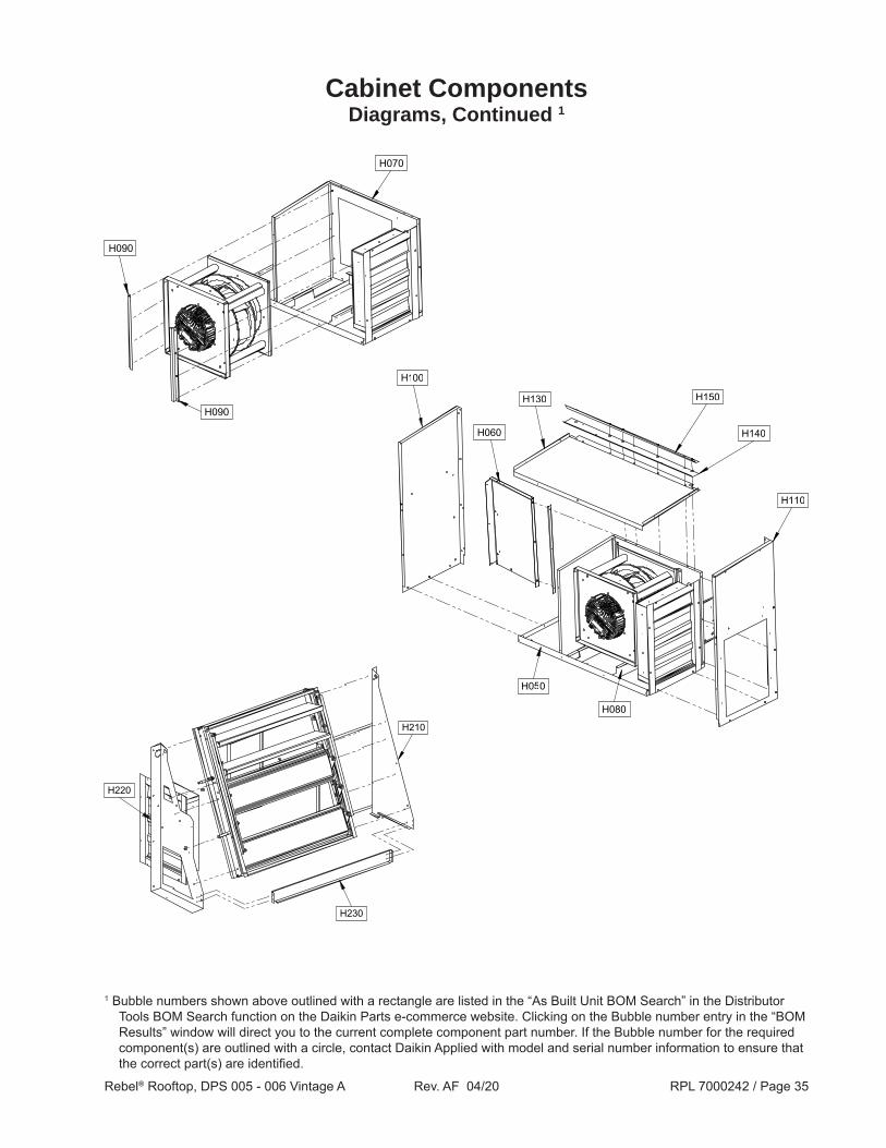
Cabinet ComponentsDiagrams, Continued 1
1 Bubble numbers shown above outlined with a rectangle are listed in the “As Built Unit BOM Search” in the Distributor Tools BOM Search function on the Daikin Parts e-commerce website. Clicking on the Bubble number entry in the “BOM Results” window will direct you to the current complete component part number. If the Bubble number for the required component(s) are outlined with a circle, contact Daikin Applied with model and serial number information to ensure that the correct part(s) are identified.
OPTIONAL
OPTIONAL
Rebel® Rooftop, DPS 005 - 006 Vintage A Rev. AF 04/20 RPL 7000242 / Page 35
Cabinet ComponentsDiagrams, Continued 1
1 Bubble numbers shown above outlined with a rectangle are listed in the “As Built Unit BOM Search” in the Distributor Tools BOM Search function on the Daikin Parts e-commerce website. Clicking on the Bubble number entry in the “BOM Results” window will direct you to the current complete component part number. If the Bubble number for the required component(s) are outlined with a circle, contact Daikin Applied with model and serial number information to ensure that the correct part(s) are identified.

Rebel® Rooftop, DPS 005 - 006 Vintage A Rev. AF 04/20 RPL 7000242 / Page 36
Cabinet ComponentsCommon Cabinet Hardware & Gaskets 1
Ref. # Description Part Number
U002 Screw (6pc. per door) 10-16 x .50” 038990703
U321 Gasket, D-Style .36 x .50” 910121567 2
U322 Gasket, D-Style .750” x .562” 059444001 2
U501 Hinge (3pc. per door) 2.0 x 1.5” 032457700
U521 Latch (3pc. per door) 113174001 1 For Cabinet part numbers not shown above, contact Daikin Applied with model and serial number information to ensure
that the correct part(s) are identified.2 Quantity and/or length varies by location.
OPTIONAL
OPTIONAL
U501U002
U521
U321 U322

Rebel® Rooftop, DPS 005 - 006 Vintage A Rev. AF 04/20 RPL 7000242 / Page 37
Controls (9/12 & Before)Control Box Diagrams
Main Control Box
208/230V Inverter Panel: Code 07= 2*, 3*
460V Inverter Panel: Code 07= 4*
1 The above diagram show typical Control Panel layouts and are to be used for reference only. Specific unit configuration may differ depending upon options selected.

Rebel® Rooftop, DPS 005 - 006 Vintage A Rev. AF 04/20 RPL 7000242 / Page 38
1 Note that all units will have a label similar to the one shown above located on the Control Box Access Door. This label contains schematic designators, part descriptions, and Daikin Applied part numbers. The label shown above is for representative purposes only. Actual part numbers will vary depending upon unit size and options selected.
Controls (9/12 & Before)Control Box Component Label Diagram 1

Rebel® Rooftop, DPS 005 - 006 Vintage A Rev. AF 04/20 RPL 7000242 / Page 39
Ref. # Description Part Number
Control Boards MCB MicroTech III Controller 1 193407301 - Battery, MCB 193409001 EXPB, D Controller Extension/Expansion Module 193407501 - Connector Extension I/O Direct Connect 3 193409701 IFB Interface Board 250691201 - Standoff, IFB (4pc. required) 3 048166705 IFBF Electrical Noise Filter & Harness Assembly, IFB 3 099495001 RHB1 Reheat Board, Hot Gas (MHGR) 113168901 - MicroTech III Remote Unit Keypad 3 193408003
Communication Modules 2 BNIP BACnet/IP Communication Module Kit 4 090016709 BNMS BACnet/MSTP Communication Module Kit 4 090016710 LNWK LON DAC Communication Module Kit 4 090016712 - Connector, Communication Module to MCB 3 300047027
Connectors - Connector, 2-Pin Spring Cage, Top Entry 3 193410302 - Connector, 3-Pin Spring Cage, Top Entry 3 193410303 - Connector, 5-Pin Spring Cage, Top Entry 3 193410305 - Connector, 6-Pin Spring Cage, Top Entry 3 193410306 - Connector, 7-Pin Spring Cage, Top Entry 3 193410307 - Connector, 8-Pin Spring Cage, Top Entry 3 193410308
Sensors/Transducers/Pressure Switches DAT Temperature Sensor, Discharge Air 3 193414602 DFT Temperature Sensor, Defrost 3 910124895 DRT Temperature Sensor, Refrigerant Discharge 3 910123800 LCT Temperature Sensor, Leaving Coil 3 193414602 IRT Temperature Sensor, Indoor Refrigerant 3 910124894 OAT Temperature Sensor, Outside Air 3 910124895 ORT Temperature Sensor, Outdoor Refrigerant 3 910124894 RAT Temperature Sensor, Return Air 3 193414602 SRT Temperature Sensor, Refrigerant Suction 3 910124895 SHS1 Sensor, Humidity Duct Mounted 3 067295001 SHS1 Sensor, Humidity Wall Mounted 3 067294901 SPS1 Pressure Transducer (7/12 & Earlier) 5 193422203 SPS2 Pressure Transducer (7/12 & Earlier) 5 193422202 PC5 Switch, Dirty Filter 349956812 DHL Switch, Duct High Limit 349956813
Controls (9/12 & Before) Common Control Box Components
1 This Controller must be programmed in order to function correctly. When ordering a replacement, provide the unit model and serial number so that unit specific software code can be loaded before shipment.
2 The Communication Module position is shown as “COM” on the Control Box diagram.3 Not shown on diagram.4 The Communication Module Kit contains the Communication Module, Connector, and Installation Instructions.5 For units built 8/12 thru 9/12 use the Distributor Tools BOM Search function on the Daikin Parts website or contact Daikin
Applied with model and serial number information to ensure that the correct part(s) are identified.

Rebel® Rooftop, DPS 005 - 006 Vintage A Rev. AF 04/20 RPL 7000242 / Page 40
Relays OAER Relay, Outside Air Enthalpy 330278110 R63 Relay, Duct High Limit 330278110 R-CCH1 Relay, Compressor Crankcase Heater 349934724 R-HP1 Relay, Compressor #1 High Pressure 349934724 - Relay Socket 1 074805901
Miscellaneous Components GFR Board, Ground Fault Relay 193520101 - CT (Current Transformer), GFR Board 1 300058145 GLG1 Ground Lug 349938011 M1F Ferrite Core (used on the Compressor Harness) 1 193495202 OF1F Noise Filter #1, Outdoor Fan 1 208/230V 193495203 OF2F Noise Filter #2, Outdoor Fan 1 460V 193495204 PVM1 Phase Voltage Monitor 190- 480V 112022001 REC1 Receptacle, Ground Fault 1 15A, 120V 039003600 ZNT1 Sensor, Digital- Zone Temperature w/ Tenant O/R & Setpoint Adj. 1, 2 910143408 Sensor- Zone Temperature w/ Tenant Override 1, 2 113117701 Sensor- Zone Temp. w/ Tenant Override & Remote Setpoint Adj. 1, 2 113117801 - CO2 Sensor, Duct Mounted 1 910111672 CO2 Sensor, Space Mounted 1 107287012
Controls (9/12 & Before) Common Control Box Components, Continued
Ref. # Description Part Number
1 Not shown on diagram. 2 In late 2013, Digital Room Sensor p/n 910143408 was added as the preferred option however, any one of these sensors
can be used. For positive p/n identification, refer to the drawings below.
10
50
1456
22
68
30
86
2680
°F
°C
62 7418
ZNT1 Sensor910143408
ZNT1 Sensor113117701
ZNT1 Sensor113117801

Rebel® Rooftop, DPS 005 - 006 Vintage A Rev. AF 04/20 RPL 7000242 / Page 41
Controls (9/12 & Before) Inverter Panel Components
Ref. # Description Part Number
A4P Control Board, Inverter Control Primary 193494702 DKND3 D3 Gateway VRV Communication Card 250800301
EVB Control Board, Expansion Valve 193494901 - EVB Standoff (4pc. required) 1 048166705
EVBF Electrical Noise Filter, EVB 1 193495203
LR1 Line Reactor 193494502
208/230V Inverter Panel: Code 07= 2*, 3*
Ref. # Description Part Number
A4P Control Board, Inverter Control Primary 193494701
A5P Control Board, Inverter Control Secondary 193494803
DKND3 D3 Gateway VRV Communication Card 250800301
EVB Control Board, Expansion Valve 193494901 - EVB Standoff (4pc. required) 2 048166705 EVBF Electrical Noise Filter, EVB 2 193495203
LR1 Line Reactor 193494501
460V Inverter Control Panel: Code 07= 4*
1 Not shown on diagram.
2 Not shown on diagram.
Rebel® Rooftop, DPS 005 - 006 Vintage A Rev. AF 04/20 RPL 7000242 / Page 42
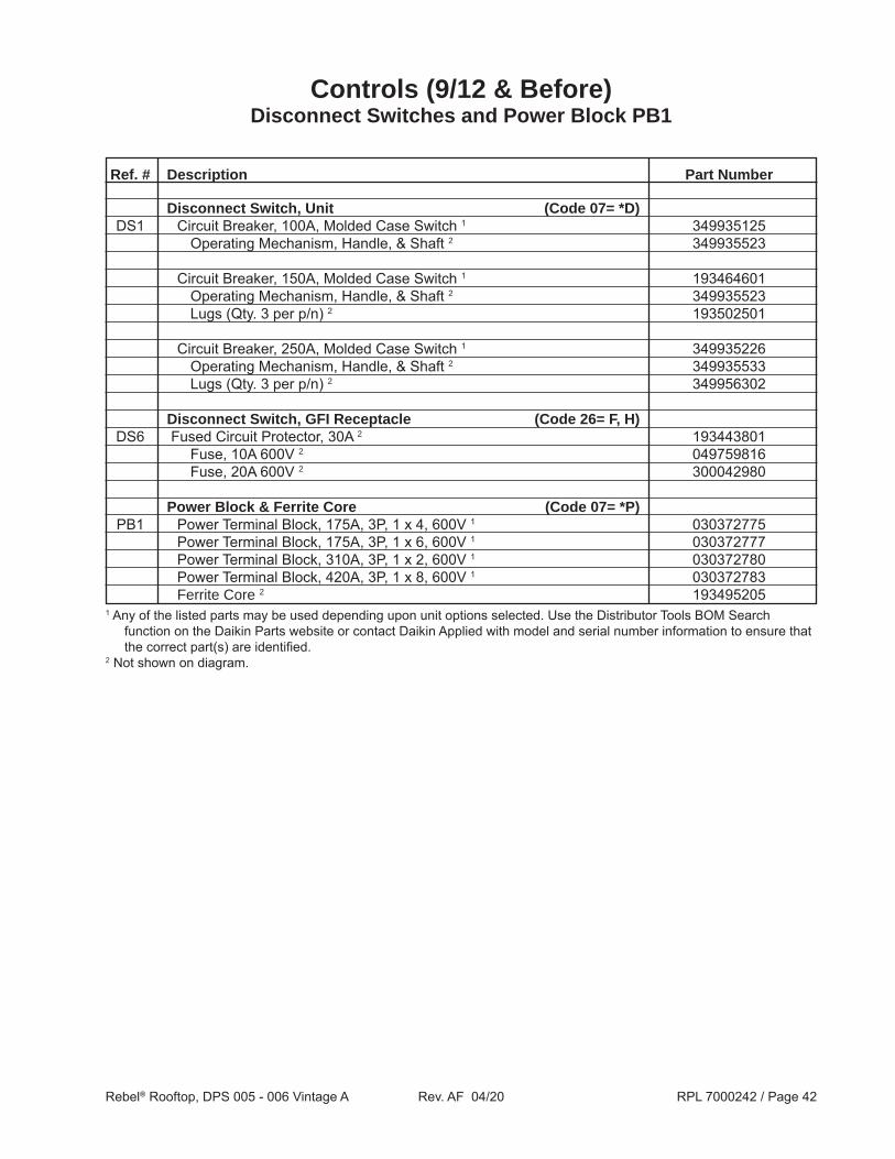
Ref. # Description Part Number
Disconnect Switch, Unit (Code 07= *D) DS1 Circuit Breaker, 100A, Molded Case Switch 1 349935125 Operating Mechanism, Handle, & Shaft 2 349935523
Circuit Breaker, 150A, Molded Case Switch 1 193464601 Operating Mechanism, Handle, & Shaft 2 349935523 Lugs (Qty. 3 per p/n) 2 193502501
Circuit Breaker, 250A, Molded Case Switch 1 349935226 Operating Mechanism, Handle, & Shaft 2 349935533 Lugs (Qty. 3 per p/n) 2 349956302
Disconnect Switch, GFI Receptacle (Code 26= F, H) DS6 Fused Circuit Protector, 30A 2 193443801 Fuse, 10A 600V 2 049759816 Fuse, 20A 600V 2 300042980
Power Block & Ferrite Core (Code 07= *P) PB1 Power Terminal Block, 175A, 3P, 1 x 4, 600V 1 030372775 Power Terminal Block, 175A, 3P, 1 x 6, 600V 1 030372777 Power Terminal Block, 310A, 3P, 1 x 2, 600V 1 030372780 Power Terminal Block, 420A, 3P, 1 x 8, 600V 1 030372783 Ferrite Core 2 193495205
Controls (9/12 & Before) Disconnect Switches and Power Block PB1
1 Any of the listed parts may be used depending upon unit options selected. Use the Distributor Tools BOM Search function on the Daikin Parts website or contact Daikin Applied with model and serial number information to ensure that the correct part(s) are identified.
2 Not shown on diagram.

Rebel® Rooftop, DPS 005 - 006 Vintage A Rev. AF 04/20 RPL 7000242 / Page 43
Ref. # Description Part Number 208V 230V 460V 575V
Units without Gas Heat (Code 06= E, W, Y) T1 Transformer, 208/277/380V, 250VA 038253910 1 Transformer, 208/480V x 120/240V, 250VA 193475303 1 1 1 F1A, B Fuse, 4A Delay, 600 VAC 049759810 2 2 Fuse, 2A Delay, 600 VAC 049759807 2 2
F1C Fuse, Midget 4A Delay, 500 VAC 4EHG7663 1 1 1 1
Units with Gas Heat (Code 06= G) T1 Transformer, 208/277/380, 500VA 193475305 1 Transformer, 480/240V x 240/120, 500VA 193475306 1 1 1
F1A, B Fuse, 6A Delay, 600 VAC 300041289 2 2 Fuse, 4A Delay, 600 VAC 049759810 2 2
F1C Fuse, Midget 7A Delay, 500 VAC 042753117 1 1 1 1 Fuses All Units F1D Fuse, Midget 3A Delay, 500 VAC 1 042753111 1 1 1 1 Fuse, Midget 4A Delay, 500 VAC 1 4EHG7663 1 1 1 1 Fuse Block 300043362 1 1 1 1 Fuse Cover/Puller 349938227 1 1 1 1
F4A- C Fuse, 0.5A Delay, 600 VAC 2 049759802 1 1 1 1 Fuse Block 2 023780232 1 1 1 1 Fuse Cover/Puller 2 349938230 1 1 1 1
F6C Fuse, 0.5A Delay, 600 VAC 042753123 1 1 1 1 Fuse Block 2 023780223 1 1 1 1 Fuse Cover/Puller 2 349938227 1 1 1 1
Controls (9/12 & Before)Transformers, Fuses, & Terminal Blocks
1 Any of the listed parts may be used depending upon unit options selected. Check the installed part to verify, use the Distributor Tools BOM Search function on the Daikin Parts website, or contact Daikin Applied with model and serial number information to ensure that the correct part(s) are identified.
2 Not shown on diagram.

Rebel® Rooftop, DPS 005 - 006 Vintage A Rev. AF 04/20 RPL 7000242 / Page 44
Controls (9/12 & Before)Transformers, Fuses, & Terminal Blocks, Continued
Ref. # Description Part Number 208V 230V 460V 575V Transformers All Units T2A, B Transformer, 120V/24V, 75VA 349937303 2 2 2 2
T4 Transformer, Auto, 460/380, 1290VA 193528101 NA NA 1 1 T6 Transformer, 1.5 KVA 038253916 1 Transformer, 1.5 KVA 038253907 1 1 Transformer, 1.5 KVA 038253984 1
T7 Transformer, 120V/24V, 50VA (Code 18= M) 349937203 1 1 1 1
- Fuse Puller Kit 1 349955801 1 1 1 1 - Ferrite Core 1 193495205 1 1 1 1 - Fuse Kit 1 193514201 1 1 1 1
Terminal Blocks All Units 2
TB1 Terminal Block, Internal Power Distribution 349930647 var. var. var. var. Terminal Block, Jumper Ports 349930641 var. var. var. var. Terminal Block, End Plate 349930741 var. var. var. var. Terminal Block, End Stop 349930841 var. var. var. var. Terminal Block, Jumper 349930942 var. var. var. var.
TB2 Terminal Block, Internal Power Distribution 349930647 var. var. var. var. Terminal Block, Jumper Ports 349930641 var. var. var. var. Terminal Block, End Plate 349930741 var. var. var. var. Terminal Block, End Stop 349930841 var. var. var. var.
TB8 Terminal Block, Internal Signal Distribution 349930647 var. var. var. var. Terminal Block, Jumper Ports 349930641 var. var. var. var. Terminal Block, End Plate 349930741 var. var. var. var. Terminal Block, End Stop 349930841 var. var. var. var.1 Not shown on diagram.2 Note that Terminal Blocks are assemblies made up of various components. Confirm the type and quantity of components
needed or contact Daikin Applied with model and serial number information BEFORE ordering.

Rebel® Rooftop, DPS 005 - 006 Vintage A Rev. AF 04/20 RPL 7000242 / Page 45
Controls (9/12 & Before)Motor Protector MMP1 2
Unit Size 005 006 Ref, # Part Part Description Number
Compressor #1 A4P Board MMP MMP1 Manual Motor Protector 24- 32A 349934035 1 1 1 1 1 1 1 1
Manual Motor Protector 20- 25A 349934034 1 1 1 1 1 1 1 1
Manual Motor Protector 17- 23A 349934033 1 1 1 1 1 1 1 1
Manual Motor Protector 13- 18A 349934032 1 1 1 1 1 1 1 1
Manual Motor Protector 9- 14A 349934031 1 1 1 1 1 1 1 1
Manual Motor Protector 6- 10A 349934030 1 1 1 1 1 1 1 1
Manual Motor Protector 4- 6.3A 300040709 1 1 1 1 1 1 1 1
Manual Motor Protector 2.5- 4A 349934028 1 1 1 1 1 1 1 1
Manual Motor Protector 1.6- 2.5A 349934027 1 1 1 1 1 1 1 1
Manual Motor Protector 1.0-1.6A 349934026 1 1 1 1 1 1 1 1
Manual Motor Protector .63- 1A 349934045 1 1 1 1 1 1 1 1
208V
230V
460V
575V
208V
230V
460V
575V
1 Any of the listed parts may be used depending upon unit options selected. Use the Distributor Tools BOM Search function on the Daikin Parts website or contact Daikin Applied with model and serial number information to ensure that the correct part(s) are identified.
2 Note that there is NO M1 Contactor as Compressor #1 is controlled by Inverter Control Board A4P.

Rebel® Rooftop, DPS 005 - 006 Vintage A Rev. AF 04/20 RPL 7000242 / Page 46
Controls (9/12 & Before)Motor Protectors MMP10 & MMP51
Ref. # Description Part Number Qty.
Supply Fan MMP MMP10 208V (Code 07= 2*) 12” Fan, 1.3HP Motor (Code 22= 12DY AND Code 21= EM) 349934028 1 14” Fan, 2.3HP Motor (Code 22= 14DY AND Code 21= GM) 300040709 1 16” Fan, 4.0HP Motor (Code 22= 16DY AND Code 21= HM) 349934030 1
230V (Code 07= 3*) 12” Fan, 1.3HP Motor (Code 22= 12DY AND Code 21= EM) 349934028 1 14” Fan, 2.3HP Motor (Code 22= 14DY AND Code 21= GM) 300040709 1 16” Fan, 4.0HP Motor (Code 22= 16DY AND Code 21= HM) 349934030 1
460V (Code 07= 4*) 12” Fan, 1.3HP Motor (Code 22= 12DY AND Code 21= EM) 349934026 1 14” Fan, 2.3HP Motor (Code 22= 14DY AND Code 21= GM) 349934027 1 16” Fan, 4.0HP Motor (Code 22= 16DY AND Code 21= HM) 300040709 1
Exhaust Fan MMP (Code 36 CANNOT= YYYY) MMP51 208V (Code 07= 2*) 12” Fan, 1.3HP Motor (Code 36= 12DY AND Code 35= EM) 349934028 1 14” Fan, 2.3HP Motor (Code 36= 14DY AND Code 35= GM) 300040709 1
230V (Code 07= 3*) 12” Fan, 1.3HP Motor (Code 36= 12DY AND Code 35= EM) 349934028 1 14” Fan, 2.3HP Motor (Code 36= 14DY AND Code 35= GM) 300040709 1
460V (Code 07= 4*) 12” Fan, 1.3HP Motor (Code 36= 12DY AND Code 35= EM) 349934026 1 14” Fan, 2.3HP Motor (Code 36= 14DY AND Code 35= GM) 349934027 1

Rebel® Rooftop, DPS 005 - 006 Vintage A Rev. AF 04/20 RPL 7000242 / Page 47
Controls (11/12 & Later)Control Box Diagrams 1
Main Control Box
208/230V Inverter Panel: Code 07= 2*, 3*
460V Inverter Panel: Code 07= 4*
COM
CHK 1 SPD1
PVM1
T7
RHB1
B+ 1
P
RI
2
3
SEC
4
24V-24V+GNDINRGW
-
MMP60
M60
EXPB
OAER
TB6
A4P
LR1
EVB
1 The above diagrams show a typical Control Panel layout and are to be used for reference only. Specific unit configuration may differ depending upon options selected.
A4P
EVB
A5P
LR1

Rebel® Rooftop, DPS 005 - 006 Vintage A Rev. AF 04/20 RPL 7000242 / Page 48
1 For units built 10/12, use the Distributor Tools BOM Search function on the Daikin Parts website or contact Daikin Applied with model and serial number information to ensure that the correct part(s) are identified.
2 Note that all units will have a label similar to the one shown above located on the Control Box Access Door. This label contains schematic designators, part descriptions, and Daikin Applied part numbers. The label shown above is for representative purposes only. Actual part numbers will vary depending upon unit size and options selected.
Controls (11/12 & Later) 1
Control Box Component Label Diagram 2

Rebel® Rooftop, DPS 005 - 006 Vintage A Rev. AF 04/20 RPL 7000242 / Page 49
Ref. # Description Part Number Control Boards MCB MicroTech III Controller 2 193407301 - Battery, MCB 193409001 EXPB, D Controller Extension/Expansion Module 193407501 - Connector Extension, I/O Direct Connect 4 193409701 IFB Interface Board 250691201 - Standoff, IFB (4pc. required) 4 048166705 IFBF Electrical Noise Filter & Harness Assembly, IFB 4 099495001 RHB1 Reheat Board, Hot Gas (MHGR) 113168901 - MicroTech III Remote Unit Keypad 4 193408003
Communication Modules 3 BNIP BACnet/IP Communication Module Kit 5 090016709 BNMS BACnet/MSTP Communication Module Kit 5 090016710 LNWK LON DAC Communication Module Kit 5 090016712 - Connector, Communication Module to MCB 4 300047027 DKND3 D3-NET Communication Gateway 250800301
Connectors - Connector, 2-Pin Spring Cage, Top Entry 4 193410302 - Connector, 3-Pin Spring Cage, Top Entry 4 193410303 - Connector, 5-Pin Spring Cage, Top Entry 4 193410305 - Connector, 6-Pin Spring Cage, Top Entry 4 193410306 - Connector, 7-Pin Spring Cage, Top Entry 4 193410307 - Connector, 8-Pin Spring Cage, Top Entry 4 193410308
Sensors/Transducers/Pressure Switches DAT Temperature Sensor, Discharge Air 4 193414602 DFT Temperature Sensor, Defrost 4 910124895 DRT Temperature Sensor, Refrigerant Discharge 4 910123800 LCT Temperature Sensor, Leaving Coil 4 193414602 IRT Temperature Sensor, Indoor Refrigerant 4 910124894 OAT Temperature Sensor, Outside Air 4 910124895 ORT Temperature Sensor, Outdoor Refrigerant 4 910124894 RAT Temperature Sensor, Return Air 4 193414602 SRT Temperature Sensor, Refrigerant Suction 4 910124895 SHS1 Sensor, Humidity Duct Mounted 4 11/12 thru 12/16 067295001 Sensor, Humidity Duct Mounted 4 1/17 & Later 910190890 SHS1 Sensor, Humidity Wall Mounted 4 067294901 SPS1 Pressure Transducer (1/13 & Later) 6 193552102 SPS2 Pressure Transducer (1/13 & Later) 6 193552101 PC5 Switch, Dirty Filter 349956812 DHL Switch, Duct High Limit 349956813
Controls (11/12 & Later) 1
Common Control Box Components
1 For units built 10/12, use the Distributor Tools BOM Search function on the Daikin Parts website or contact Daikin Applied with model and serial number information to ensure that the correct part(s) are identified.
2 This Controller must be programmed in order to function correctly. When ordering a replacement, provide the unit model and serial number so that unit specific software code can be loaded before shipment.
3 The Communication Module position is shown as “COM” on the Control Box diagram.4 Not shown on diagram.5 The Communication Module Kit contains the Communication Module, Connector, and Installation Instructions.6 For units built 11/12 thru 12/12 use the Distributor Tools BOM Search function on the Daikin Parts website or contact
Daikin Applied with model and serial number information to ensure that the correct part(s) are identified.

Rebel® Rooftop, DPS 005 - 006 Vintage A Rev. AF 04/20 RPL 7000242 / Page 50
Relays OAER Relay, Outside Air Enthalpy 330278110 R63 Relay, Duct High Limit 330278110 R-CCH1 Relay, Compressor Crankcase Heater 349934724 R-HP1 Relay, Compressor #1 High Pressure 349934724 - Relay Socket 2 074805901
Energy Recovery Wheel Components M60 Contactor, Energy Recovery Wheel 7A 193535113 MMP60 Motor Protector, Energy Recovery Wheel .28- .4A 6/18 & Earlier 193542916 Motor Protector, Energy Recovery Wheel .7- 1.0A 7/18 & Later 193542903 - Link, M60 to MMP60 2 193545901 - Phase Barrier, Motor Protector 2 193545501
Miscellaneous Components CHK/CHK1 Power Filter, Interface Board (IFB) 099495002 GFR/GFR1 Board, Ground Fault Relay 193520101 - CT (Current Transformer), GFR Board 2 300058145 GLG1 Ground Lug 349938011 M1F Ferrite Core (used on the Compressor Harness) 2 193495202 OF1F Noise Filter #1, Outdoor Fan 2 208/230V 193495203 OF2F Noise Filter #2, Outdoor Fan 2 460V 193495204 PVM1 Phase Voltage Monitor 3 12/12 & Later 193599301 - Socket, Phase Voltage Monitor 2, 3 12/12 & Later 193599401 REC1 Receptacle, Ground Fault 2 15A, 120V 039003600 SPD/SPD1 Surge Arrestor 332606801 ZNT1 Sensor, Digital- Zone Temperature w/ Tenant O/R & Setpoint Adj. 2, 4 910143408 Sensor- Zone Temperature w/ Tenant Override 2, 4 113117701 Sensor- Zone Temp. w/ Tenant Override & Remote Setpoint Adj. 2, 4 113117801 - CO2 Sensor, Duct Mounted 2 910111672 CO2 Sensor, Space Mounted 2 107287012
Controls (11/12 & Later) 1
Common Control Box Components, Continued
Ref. # Description Part Number
1 For units built 10/12, use the Distributor Tools BOM Search function on the Daikin Parts website or contact Daikin Applied with model and serial number information to ensure that the correct part(s) are identified.
2 Not shown on diagram.3 Note that some units built in 11/12 may have PVM1 p/n 112022001 installed. If unsure as to which PVM1 is installed, use
the Distributor Tools BOM Search function on the Daikin Parts website or contact Daikin Applied with model and serial number information to ensure that the correct part(s) are identified.
4 In late 2013, Digital Room Sensor p/n 910143408 was added as the preferred option. The other Zone Temperature Sensors are available as options. For positive p/n identification, refer to the drawings below.
10
50
1456
22
68
30
86
2680
°F
°C
62 7418
ZNT1 Sensor910143408
ZNT1 Sensor113117701
ZNT1 Sensor113117801

Rebel® Rooftop, DPS 005 - 006 Vintage A Rev. AF 04/20 RPL 7000242 / Page 51
Controls (11/12 & Later) 1
Inverter Control Panel Components
Ref. # Description Part Number
A4P Control Board, Inverter Control Primary 193494702 EVB Control Board, Expansion Valve 193494901
- Spacer/Support, Control Board (Qty. 4) 2 910146598
LR1 Line Reactor 193494502
208/230V Inverter Control Panel: Code 07= 2*, 3*
460V Inverter Control Panel: Code 07= 4* Ref. # Description Part Number
A4P Control Board, Inverter Control Primary 193494701
A5P Control Board, Inverter Control Secondary 193494803
EVB Control Board, Expansion Valve 193494901
- Spacer/Support, Control Board (Qty. 4) 3 910146598
LR1 Line Reactor 193494501
1 For units built 10/12, use the Distributor Tools BOM Search function on the Daikin Parts website or contact Daikin Applied with model and serial number information to ensure that the correct part(s) are identified.
2 Not shown on diagram.
1 For units built 10/12, use the Distributor Tools BOM Search function on the Daikin Parts website or contact Daikin Applied with model and serial number information to ensure that the correct part(s) are identified.
3 Not shown on diagram.

Rebel® Rooftop, DPS 005 - 006 Vintage A Rev. AF 04/20 RPL 7000242 / Page 52
Ref. # Description Part Number
Disconnect Switch, Unit (Code 07= *D) 4
DS1 Circuit Breaker, 100A, Molded Case Switch 2 193444703 Handle 3 300040563 Shaft 3 193557701
Circuit Breaker, 150A, Molded Case Switch 2 193585101 Operating Mechanism 3 193550801 Handle 3 300040563 Shaft 3 193557701 Lug Kit, Line & Load (Qty. 3 per p/n) 3 193553301
Circuit Breaker, 225A, Molded Case Switch 2 193585102 Operating Mechanism 3 193550801 Handle 3 300040563 Shaft 3 193557701 Lugs, Line & Load (Qty. 3 per p/n) 3 193553301
Disconnect Switch, GFI Receptacle (Code 26= F, H) DS6 Fused Circuit Protector 193443801 Fuse, 10A 600V 2 049759816 Fuse, 20A 600V 2 300042980
Power Block & Ferrite Core (Code 07= *P) 4
PB1 Power Terminal Block, 175A, 3P, 1 x 4, 600V 2 030372775 Power Terminal Block, 175A, 3P, 1 x 6, 600V 2 030372777 Power Terminal Block, 310A, 3P, 1 x 2, 600V 2 030372780 Power Terminal Block, 420A, 3P, 1 x 8, 600V 2 030372783 Ferrite Core 3 193495205
Controls (11/12 & Later) 1, 4
Disconnect Switches and Power Block PB1
1 For units built 10/12, use the Distributor Tools BOM Search function on the Daikin Parts website or contact Daikin Applied with model and serial number information to ensure that the correct part(s) are identified.
2 Any of the listed parts may be used depending upon unit options selected. Use the Distributor Tools BOM Search function on the Daikin Parts website or contact Daikin Applied with model and serial number information to ensure that the correct part(s) are identified.
3 Not shown on diagram.4 For units with Dual Power Blocks (Code 07= *R) OR for units with Dual Power Supply with Disconnect Switch (Code 07=
*C) use the Distributor Tools BOM Search function on the Daikin Parts website or contact Daikin Applied with model and serial number information to ensure that the correct part(s) are identified.

Rebel® Rooftop, DPS 005 - 006 Vintage A Rev. AF 04/20 RPL 7000242 / Page 53
Ref. # Description Part Number 208V 230V 460V
Units w/o Gas Heat (Code 06= E, W, Y) T1 Transformer, 250VA 2/14 & Earlier 1 099477901 1 Transformer, 300VA 4/14 thru 4/18 1 099477202 1 Transformer, 300VA 6/18 & Later 1 349948105 1 Transformer, 250VA 8/13 & Earlier 1 099477801 1 Transformer, 300VA 11/13 thru 5/18 1 099477102 1 Transformer, 300VA 6/18 & Later 1 349948101 1 Transformer, 250VA 9/13 & Earlier 1 099477801 1 Transformer, 300VA 11/13 thru 4/18 1 099477102 1 Transformer, 300VA 6/18 & Later 1 349948101 1 F1A, B Fuse, 4A 349937123 2 2 Fuse, 2A 4/18 & Earlier 1 349937116 2 Fuse, 1.5A 6/18 & Later 1 349937113 2 F1C Fuse, 4A 349937023 1 1 1 - Fuse Holder 2/14 & Earlier 1 193514201 1 - Fuse Holder 9/13 & Earlier 1 193514201 1 1 - Fuse Holder 6/18 & Later 1 349948901 1 1 1 - Fuse Puller 2/14 & Earlier 1 349955801 1 - Fuse Puller 9/13 & Earlier 1 349955801 1 1 - Fuse Puller 6/18 & Later 1 349949201 1 1 1 - Fuse Cover 4/14 thru 4/18 1 099477402 1 - Fuse Cover 11/13 thru 4/18 1 099477402 1 1 - Terminal Cover 4/14 thru 4/18 1 193596801 1 - Terminal Cover 11/13 thru 4/18 1 193596801 1 1 - Sec. Term. Cover 6/18 & Later 1 349949101 1 1 1
Controls (11/12 & Later) 2
Transformers, Fuses, & Terminal Blocks
1 For units built during the transition, use the Distributor Tools BOM Search function on the Daikin Parts website or contact Daikin Applied with model and serial number information to ensure that the correct part(s) are identified.
2 For units built 10/12, use the Distributor Tools BOM Search function on the Daikin Parts website or contact Daikin Applied with model and serial number information to ensure that the correct part(s) are identified.
Rebel® Rooftop, DPS 005 - 006 Vintage A Rev. AF 04/20 RPL 7000242 / Page 54
Ref. # Description Part Number 208V 230V 460V
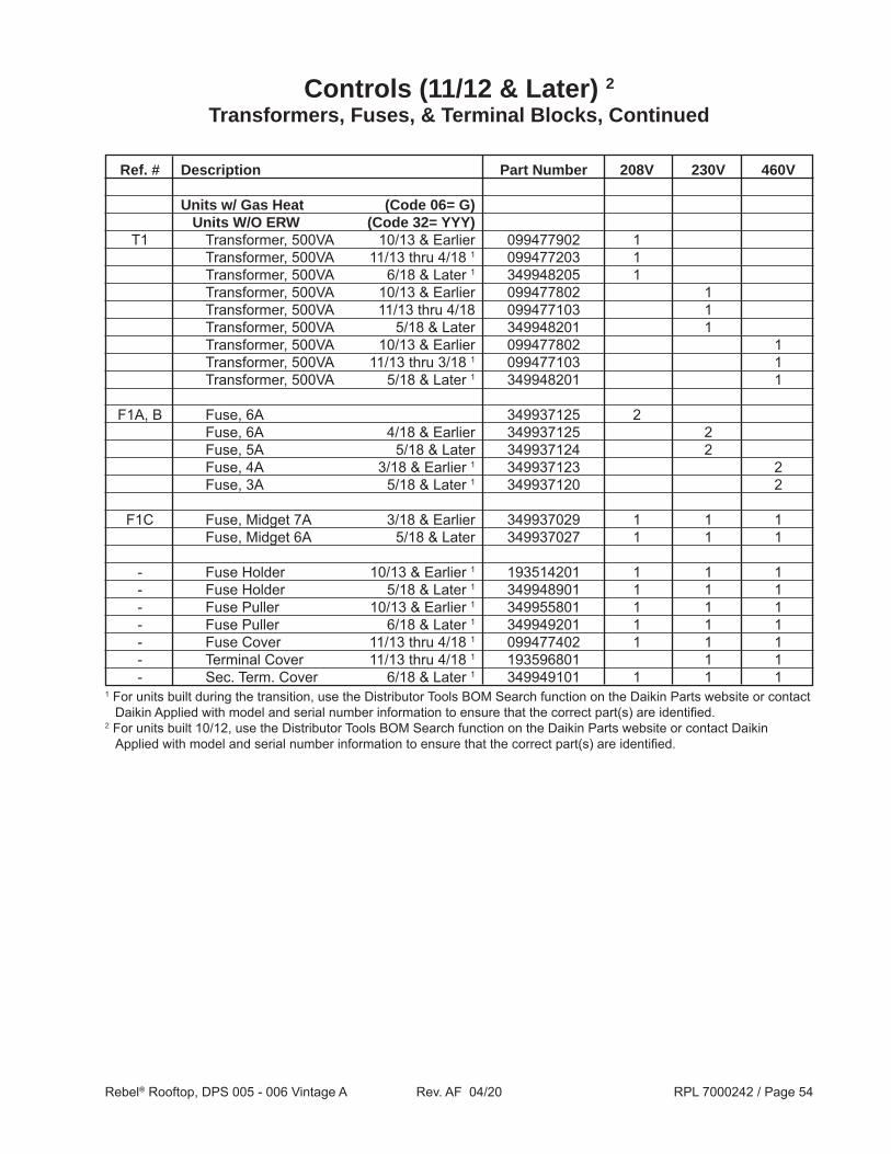
Units w/ Gas Heat (Code 06= G) Units W/O ERW (Code 32= YYY) T1 Transformer, 500VA 10/13 & Earlier 099477902 1 Transformer, 500VA 11/13 thru 4/18 1 099477203 1 Transformer, 500VA 6/18 & Later 1 349948205 1 Transformer, 500VA 10/13 & Earlier 099477802 1 Transformer, 500VA 11/13 thru 4/18 099477103 1 Transformer, 500VA 5/18 & Later 349948201 1 Transformer, 500VA 10/13 & Earlier 099477802 1 Transformer, 500VA 11/13 thru 3/18 1 099477103 1 Transformer, 500VA 5/18 & Later 1 349948201 1 F1A, B Fuse, 6A 349937125 2 Fuse, 6A 4/18 & Earlier 349937125 2 Fuse, 5A 5/18 & Later 349937124 2 Fuse, 4A 3/18 & Earlier 1 349937123 2 Fuse, 3A 5/18 & Later 1 349937120 2 F1C Fuse, Midget 7A 3/18 & Earlier 349937029 1 1 1 Fuse, Midget 6A 5/18 & Later 349937027 1 1 1 - Fuse Holder 10/13 & Earlier 1 193514201 1 1 1 - Fuse Holder 5/18 & Later 1 349948901 1 1 1 - Fuse Puller 10/13 & Earlier 1 349955801 1 1 1 - Fuse Puller 6/18 & Later 1 349949201 1 1 1 - Fuse Cover 11/13 thru 4/18 1 099477402 1 1 1 - Terminal Cover 11/13 thru 4/18 1 193596801 1 1 - Sec. Term. Cover 6/18 & Later 1 349949101 1 1 1
Controls (11/12 & Later) 2
Transformers, Fuses, & Terminal Blocks, Continued
1 For units built during the transition, use the Distributor Tools BOM Search function on the Daikin Parts website or contact Daikin Applied with model and serial number information to ensure that the correct part(s) are identified.
2 For units built 10/12, use the Distributor Tools BOM Search function on the Daikin Parts website or contact Daikin Applied with model and serial number information to ensure that the correct part(s) are identified.

Rebel® Rooftop, DPS 005 - 006 Vintage A Rev. AF 04/20 RPL 7000242 / Page 55
Ref. # Description Part Number 208V 230V 460V
Units w/ Gas Heat (Code 06= G) Units W/ ERW (Code 32= L**, H**) T1 Transformer, 500VA 9/13 & Earlier 099477902 1 Transformer, 500VA 10/13 thru 4/18 099477203 1 Transformer, 500VA 5/18 thru 6/18 349948205 1 Transformer, 750VA 7/18 & Later 349948305 1 Transformer, 500VA 6/18 & Earlier 099477103 1 Transformer, 750VA 7/18 & Later 349948301 1 Transformer, 500VA 1/14 & Earlier 099477802 1 Transformer, 500VA 2/14 thru 4/18 099477103 1 Transformer, 500VA 5/18 thru 6/18 099477104 1 Transformer, 750VA 7/18 & Later 349948301 1 F1A, B Fuse, 6A 6/18 & Earlier 349937125 2 2 Fuse, 9A 7/18 & Later 349937130 2 Fuse 6/18 & Later 1 2 Fuse, 4A 349937123 2 F1C Fuse, Midget 7A 4/18 & Earlier 349937029 1 1 1 Fuse, Midget 5/18 thru 6/18 1 1 Fuse, Midget 10A 7/18 & Later 2 349937032 1 1 - Fuse Holder 9/13 & Earlier 2 193514201 1 - Fuse Holder 5/18 & Later 2 349948901 1 - Fuse Holder 1/14 & Earlier 2 193514201 1 - Fuse Holder 7/18 & Later 2 349948901 1 - Fuse Puller 9/13 & Earlier 349955801 1 - Fuse Puller 1/14 & Earlier 349955801 1 - Fuse Cover 099477402 1 1 - Terminal Cover 2/18 & Earlier 099477602 1 1 - Terminal Cover 3/18 & Later 099477601 1 1 - Sec. Term. Cover 6/18 & Later 349949101 1 1 1
Controls (11/12 & Later) 3
Transformers, Fuses, & Terminal Blocks, Continued
1 Use the Distributor Tools BOM Search function on the Daikin Parts website or contact Daikin Applied with model and serial number information to ensure that the correct part(s) are identified.
2 For units built during the transition, use the Distributor Tools BOM Search function on the Daikin Parts website or contact Daikin Applied with model and serial number information to ensure that the correct part(s) are identified.
3 For units built 10/12, use the Distributor Tools BOM Search function on the Daikin Parts website or contact Daikin Applied with model and serial number information to ensure that the correct part(s) are identified.

Rebel® Rooftop, DPS 005 - 006 Vintage A Rev. AF 04/20 RPL 7000242 / Page 56
Controls (11/12 & Later) 1
Transformers, Fuses, & Terminal Blocks, Continued
Ref. # Description Part Number 208V 230V 460V 575V Fuses All Units F1D Fuse, Midget 3A Delay, 500 VAC 2, 3 042753111 1 1 1 1 Fuse, Midget 4A Delay, 500 VAC 2, 3 4EHG7663 1 1 1 1 Fuse Block 3 300043362 1 1 1 1 Fuse Cover/Puller 3 349938227 1 1 1 1 F4A- C Fuse, 0.5A Delay, 600 VAC 3 049759802 1 1 1 1 Fuse Block 3 023780232 1 1 1 1 Fuse Cover/Puller 3 349938230 1 1 1 1 F6C Fuse, 0.5A Delay, 600 VAC 042753123 1 1 1 1 Fuse Block 3 023780223 1 1 1 1 Fuse Cover/Puller 3 349938227 1 1 1 1
Transformers All Units T2A, B Transformer, 75VA (12/13 & Earlier) 3 349937303 2 2 2 2 Transformer, 75VA (3/14 & Later) 3 910142353 2 2 2 2
T4 Transformer, 1290VA 2, 3 (12/14 & Earlier) 193528101 NA NA 1 1 Transformer, 600VA 2, 3 (2/15 & Later) 099494001 NA NA 1 1
T6 Transformer, 1.5 KVA (Code 26= F, H) 038253916 1 Transformer, 1.5 KVA 038253907 1 1 Transformer, 1.5 KVA 038253984 1
T7 Transformer, 120V/24V, 50VA (Code 18= M) 349937203 1 1 1 1
- Fuse Puller Kit 2 349955801 1 1 1 1 - Ferrite Core 2 193495205 1 1 1 1 - Fuse Kit 2 193514201 1 1 1 1
Terminal Blocks All Units 4
TB1 Terminal Block, Internal Power Distribution 349930647 var. var. var. var. Terminal Block, Jumper Ports 349930641 var. var. var. var. Terminal Block, End Plate 349930741 var. var. var. var. Terminal Block, End Stop 349930841 var. var. var. var. Terminal Block, Jumper 349930942 var. var. var. var.
TB2 Terminal Block, Internal Power Distribution 349930647 var. var. var. var. Terminal Block, Jumper Ports 349930641 var. var. var. var. Terminal Block, End Plate 349930741 var. var. var. var. Terminal Block, End Stop 349930841 var. var. var. var.
TB8 Terminal Block, Internal Signal Distribution 349930647 var. var. var. var. Terminal Block, Jumper Ports 349930641 var. var. var. var. Terminal Block, End Plate 349930741 var. var. var. var. Terminal Block, End Stop 349930841 var. var. var. var.1 For units built 10/12, use the Distributor Tools BOM Search function on the Daikin Parts website or contact Daikin
Applied with model and serial number information to ensure that the correct part(s) are identified.2 Not shown on diagram.3 For units built during the transition, use the Distributor Tools BOM Search function on the Daikin Parts website or contact
Daikin Applied with model and serial number information to ensure that the correct part(s) are identified.4 Note that Terminal Blocks are assemblies made up of various components. Confirm the type and quantity of components
needed or contact Daikin Applied with model and serial number information BEFORE ordering.
Rebel® Rooftop, DPS 005 - 006 Vintage A Rev. AF 04/20 RPL 7000242 / Page 57
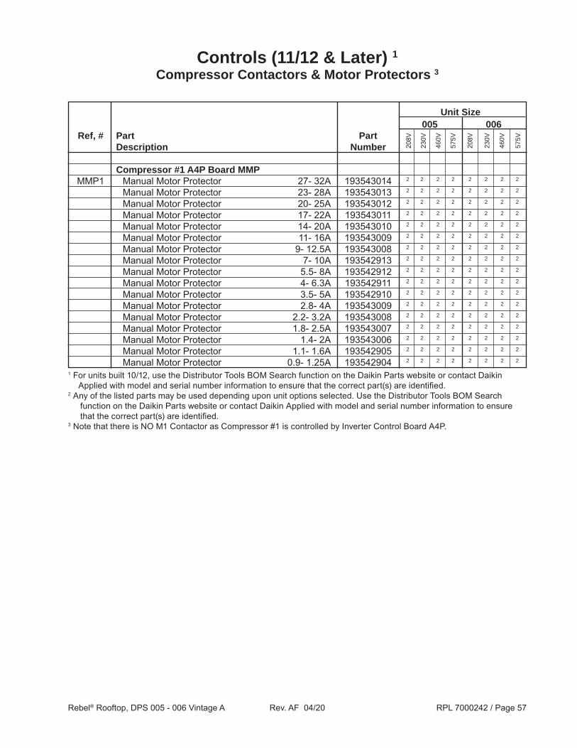
Unit Size 005 006 Ref, # Part Part Description Number
Compressor #1 A4P Board MMP MMP1 Manual Motor Protector 27- 32A 193543014 2 2 2 2 2 2 2 2
Manual Motor Protector 23- 28A 193543013 2 2 2 2 2 2 2 2
Manual Motor Protector 20- 25A 193543012 2 2 2 2 2 2 2 2
Manual Motor Protector 17- 22A 193543011 2 2 2 2 2 2 2 2
Manual Motor Protector 14- 20A 193543010 2 2 2 2 2 2 2 2
Manual Motor Protector 11- 16A 193543009 2 2 2 2 2 2 2 2
Manual Motor Protector 9- 12.5A 193543008 2 2 2 2 2 2 2 2
Manual Motor Protector 7- 10A 193542913 2 2 2 2 2 2 2 2
Manual Motor Protector 5.5- 8A 193542912 2 2 2 2 2 2 2 2
Manual Motor Protector 4- 6.3A 193542911 2 2 2 2 2 2 2 2
Manual Motor Protector 3.5- 5A 193542910 2 2 2 2 2 2 2 2
Manual Motor Protector 2.8- 4A 193543009 2 2 2 2 2 2 2 2
Manual Motor Protector 2.2- 3.2A 193543008 2 2 2 2 2 2 2 2
Manual Motor Protector 1.8- 2.5A 193543007 2 2 2 2 2 2 2 2
Manual Motor Protector 1.4- 2A 193543006 2 2 2 2 2 2 2 2
Manual Motor Protector 1.1- 1.6A 193542905 2 2 2 2 2 2 2 2
Manual Motor Protector 0.9- 1.25A 193542904 2 2 2 2 2 2 2 2
208V
230V
460V
575V
208V
230V
460V
575V
1 For units built 10/12, use the Distributor Tools BOM Search function on the Daikin Parts website or contact Daikin Applied with model and serial number information to ensure that the correct part(s) are identified.
2 Any of the listed parts may be used depending upon unit options selected. Use the Distributor Tools BOM Search function on the Daikin Parts website or contact Daikin Applied with model and serial number information to ensure that the correct part(s) are identified.
3 Note that there is NO M1 Contactor as Compressor #1 is controlled by Inverter Control Board A4P.
Controls (11/12 & Later) 1
Compressor Contactors & Motor Protectors 3

Rebel® Rooftop, DPS 005 - 006 Vintage A Rev. AF 04/20 RPL 7000242 / Page 58
Controls (11/12 & Later) 4
Supply and Exhaust Fan Contactors & Motor Protectors
Ref. # Description Part Number Qty.
Supply Fan MMP MMP10 208V (Code 07= 2*) 12” Fan, 1.3HP Motor (Code 22= 12DY AND Code 21= EM) 193542909 1 14” Fan, 2.3HP Motor (Code 22= 14DY AND Code 21= GM) 193542911 1 16” Fan, 4.0HP Motor (Code 22= 16DY AND Code 21= HM) 193542913 1 22” Fan, 8.0HP Motor (Code 22= 22DY AND Code 21= KM) 193543009 1
230V (Code 07= 3*) 12” Fan, 1.3HP Motor (Code 22= 12DY AND Code 21= EM) 193542908 1 14” Fan, 2.3HP Motor (Code 22= 14DY AND Code 21= GM) 193542911 1 16” Fan, 4.0HP Motor (Code 22= 16DY AND Code 21= HM) 193542913 1 22” Fan, 8.0HP Motor (Code 22= 22DY AND Code 21= KM) 193543009 1
460V (Code 07= 4*) 12” Fan, 1.3HP Motor (Code 22= 12DY AND Code 21= EM) 193542905 1 14” Fan, 2.3HP Motor (Code 22= 14DY AND Code 21= GM) 193542907 1 16” Fan, 4.0HP Motor (Code 22= 16DY AND Code 21= HM) 193542912 1 22” Fan, 8.0HP Motor (Code 22= 22DY AND Code 21= KM) 193542912 1
- Bus Bar Feeder 1, 2 193545101 1 - Bus Bar, 2 Position 1, 2 193544301 1 - Phase Barrier 1, 3 193545501 1 Exhaust Fan MMP (Code 36 CANNOT= YYYY) MMP51 208V (Code 07= 2*) 12” Fan, 1.3HP Motor (Code 36= 12DY AND Code 35= EM) 193542909 1 14” Fan, 2.3HP Motor (Code 36= 14DY AND Code 35= GM) 193542911 1 16” Fan, 4.0HP Motor (Code 36= 16DY AND Code 35= HM) 193542913 1 18” Fan, 4.0HP Motor (Code 36= 18DY AND Code 35= HM) 193542913 1
230V (Code 07= 3*) 12” Fan, 1.3HP Motor (Code 36= 12DY AND Code 35= EM) 193542908 1 14” Fan, 2.3HP Motor (Code 36= 14DY AND Code 35= GM) 193542911 1 16” Fan, 4.0HP Motor (Code 36= 16DY AND Code 35= HM) 193542913 1 18” Fan, 4.0HP Motor (Code 36= 18DY AND Code 35= HM) 193542913 1
460V (Code 07= 4*) 12” Fan, 1.3HP Motor (Code 36= 12DY AND Code 35= EM) 193542905 1 14” Fan, 2.3HP Motor (Code 36= 14DY AND Code 35= GM) 193542907 1 16” Fan, 4.0HP Motor (Code 36= 16DY AND Code 35= HM) 193542912 1 18” Fan, 4.0HP Motor (Code 36= 18DY AND Code 35= HM) 193542912 11 Not shown on diagram.2 Used when there IS an Exhaust Fan (Code 36 CANNOT = YYYY).3 Used when there is NO Exhaust Fan (Code 36= YYYY).4 For units built 10/12, use the Distributor Tools BOM Search function on the Daikin Parts website or contact Daikin
Applied with model and serial number information to ensure that the correct part(s) are identified.

Rebel® Rooftop, DPS 005 - 006 Vintage A Rev. AF 04/20 RPL 7000242 / Page 59
Intelligent Equipment® from Daikin Applied (Code 20= A) is a secure, cloud-based solution that enables delivery of information to end users and/or service technicians via the web or mobile device. Intelligent Equipment measures the power and performance of every unit providing real-time data streams for benchmarking performance and monitoring system operation.
A power measurement module and communications gateway installed on Daikin Applied equipment enables the unit to be directly connected to the internet via a wireless connection (Wi-Fi, cellular) or through a local area network (LAN) providing management, monitoring, control, analysis, and decision-making functionality
IE Express™ (Code 20= L) connects directly to your Daikin unit and offers a low cost, easy to install, entry-level solution to cloud equipment controls for those who don’t need the Energy Management Module (EMM) found in the Intelligent Equipment offering.
Note that this feature may be added in the field after the initial purchase. In this case, the coding for Code 20 as shown above does NOT apply.
Click on this link to access the RPL for Intelligent Equipment: 7000506.
Intelligent Equipment (Code 20= A, L)