rq series - aaon heating and cooling products · figure 5 - u.s. wiring diagram ... class 2 dc and...
TRANSCRIPT

RQ SERIES
Variable Speed Scroll Compressor
Supplement
2
Table of Contents Variable Speed Scroll Compressor Supplement 1
RQ Series Variable Speed Compressor Components 5
Introduction 8
Variable Speed Scroll Compressors 8
Product Description 8
Compressor Motor 8
Oil Pump 8
Compressor Temperature Protection 8
Oil Recovery 8
Motor Protection 8
Starting and Stopping Routine 8
Oil Type 9
Maximum Tilt Angle 9
Contaminant Control 9
Discharge Check Valve 9
Electrical Troubleshooting 10
Three Phase Series Variable Speed Drives 11
Product Description 11
Theory of Drive Operation 11
Nomenclature 11
Temperature amp Humidity 11
Power OnOff 11
Communication Setting 11
Input Voltage and Input Current 12
Power Factor Correction 12
Speed Control 12
Fault Clearing 12
Status Indication 12
LED for COMMS MCU 12
Drive Over Temperature Protection 13
Power Interrupt 13
Air Cooled Heat Exchanger 13
Foldback 13
Troubleshooting 13
Variable Speed Compressor Temperature Control 21
Modular Silicon Expansion Valve and Universal SuperHeat ControllerSensor Hardware
Installation 22
Additional Product Markings for USHC-G13b and USHS-G13b 22
About the MSEV and USHX 22
Mechanical Installation 24
Electrical Wiring 28
Troubleshooting 32
3
Index of Tables and Figures
Tables
Table 1 - Troubleshooting ndash Fault and Protection 14
Table 2 - Communication Connector Pin Definition 18
Table 3 - Sensor Connector Pin Definition 18
Table 4 - Ramp Up Procedure 19
Table 5 - Ramp Down Sequence 19
Table 6 - Input Current Foldback 20
Table 7 - Output Current Foldback 20
Table 8 - Inverter Temperature Feedback 20
Table 9 - USHX and Wiring Harness Pin Assignments 23
Figures
Figure 1 ndash Variable Speed Scroll Design Features 10
Figure 2 ndash Motor Winding Diagram 10
Figure 3- Electronics Nomenclature 16
Figure 4 - US Drive Model Wiring Diagram 17
Figure 5 - US Wiring Diagram 17
Figure 6 - WattMaster VCC-X Controller and Refrigeration System Control Module 21
Figure 7 - Modular Silicon Expansion Valve 22
Figure 8 - USHX 22
Figure 9 - USHZ Wiring Harness 22
Figure 10 - MSEV and USHC installation schematic 24
Figure 11 - MSEV installation orientation 25
Figure 12 - USHX installation orientation on a horizontal copper line 26
Figure 13 - USHX installation orientation on vertical copper line 26
Figure 14 - Brazed access fitting 26
Figure 15 - Installed USHX with attached 10-pin wiring harness 27
Figure 16 - Thermistor installation at evaporator outlet 27
Figure 17 - Insulation secured to the thermistor 28
Figure 18 - Class 2 DC and AC power sources 29
Figure 19 - Single USHC-MSEV or single USHS wiring diagram 30
Figure 20 - USHX-to-RS485 converter connection 31
Figure 21 - MSEV electrical connections 31
V83980 Rev A 170111
4
5
RQ Series Variable Speed Compressor Components
Variable Speed Compressor
Inverter Electronic Expansion Valve
WattMaster VCC-X Controls
EC Motor Automation Control Unit
6
Variable Speed Compressor
Inverter
WattMaster VCC-X Controls
Condenser Fan EC Motor Automation
Control Unit
Electronic Expansion Valve Controller
7
Example Wiring Diagram showing WattMaster Refrigeration System Module for Variable Speed
Compressors Copeland Inverter Electronic Expansion Valve and Variable Speed Condenser
Fan Control
8
Introduction This document provides instructions on how
the variable speed scroll compressor and
inverter drive are applied to a variable speed
compressor in a safe and reliable manner
The variable speed scroll compressor will be
referred to throughout this document as the
ldquovariable speed compressorrdquo or the
ldquocompressorrdquo The inverter drive will be
referred to throughout this document as the
ldquoinverter driverdquo or simply the ldquodriverdquo
Variable Speed Scroll Compressors
Product Description
The variable speed compressor has a speed
range of 900 (refer to operating envelope for
low speed operation) to 5000 revolutions per
minute and is intended for use in
commercial air conditioning chiller and
heat pump applications The variable speed
scrolls utilize three-phase brushless
permanent magnet (BPM) motors The
compressors have been qualified for use
with drives which have been developed and
qualified for BPM motor-compressors
Compressor Motor
The brushless permanent magnet (BPM)
motor in the variable speed scroll consists of
a three-phase stator and a rotor embedded
with high energy permanent magnets The
input voltage is a series of pulses of varying
frequency at 120 degree intervals between
phases
Oil Pump
The variable speed scroll is equipped with
an oil pump to ensure an adequate supply of
oil to the bearing system throughout the
operating speed range of 900 to 5000 RPM
Compressor Temperature Protection
A discharge line thermistor must be used to
protect the compressor The drive will shut
down the compressor when the thermistor
temperature exceeds 275degF (135degC)
Oil Recovery
An oil recovery cycle is required if
compressor speed is below 1800 rpm for 2
hours When this occurs the unit controls
will increase the compressor speed to 3600
rpm for five minutes
Motor Protection
The drive includes motor protection features
for the compressor The drive sets the
maximum current limit low voltage fold
back which allows the compressor to ride
through low voltage situations which helps
keep the compressor running to avoid
nuisance trips
Starting and Stopping Routine
The drive controls the starting and stopping
routine of the variable speed scroll This
routine allows soft starting and controlled
stopping an advantage over traditional on-
off control of fixed capacity units Please
refer to Table 4 for an exact explanation of
the starting and stopping process
The variable speed scroll compressor
incorporates a fluid brake design to help
mitigate reverse rotation during shutdown A
momentary reverse rotation sound may be
heard
9
Oil Type
Variable speed scrolls are charged with
polyolester (POE) oil See the compressor
nameplate for the original oil charge A
complete recharge should be approximately
four fluid ounces (118cc) less than the
nameplate value Copelandtrade Ultra 32
3MAF available from Emerson
Wholesalers should be used if additional oil
is needed in the field Mobil Arctic
EAL22CC Emkarate RL22 Emkarate 32CF
and Emkarate 3MAF are acceptable
alternatives
Maximum Tilt Angle
Service personnel may be required to
maneuver a unit through a stairwell or other
cramped area that might require tilting the
unit The maximum allowable tilt angles
from horizontal for individual compressors
(not tandem or trio applications) are
summarized below
Max tilt angle with compressor not running = 60deg
Contaminant Control
Moisture levels should be maintained below
50 ppm for optimal performance A filter-
drier is required on all R-410A and POE
lubricant systems to prevent solid
particulate contamination oil dielectric
strength degradation ice formation oil
hydrolysis and metal corrosion
Molecular sieve and activated alumina are
two filter-drier materials designed to remove
moisture and mitigate acid formation A
100 molecular sieve filter can be used for
maximum moisture capacity A more
conservative mix such as 75 molecular
sieve and 25 activated alumina should be
used for service applications
Discharge Check Valve
The compressor uses a shutdown valve
located in the discharge fitting This check
valve is not a low-leak-back check valve and
will leak when pressure differential across
the check valve is low
POE oil must be handled carefully and the proper protective equipment (gloves eye protection etc) must be used when handling POE lubricant POE must not come into contact with any surface or material that might be harmed by POE and spills should be cleaned up quickly with paper towels
soap and water
Caution
10
Electrical Troubleshooting
The BPM motors used in the variable speed
scrolls are three-phase The three windings
should always have line to line continuity
because there is no internal overload at the
center of the motor windings to open and
take the motor off-line If one or more of the
windings shows continuity to ground the
compressor must be replaced
Measuring the current in the three individual
wires feeding the compressor will provide
no useful information to the service
technician other than to show that each
winding of the compressor is drawing
current The more appropriate measurement
is the current input to the drive Current
input to the drive can be compared to the
published values of MCC and RLA
Figure 1 ndash Variable Speed Scroll Design Features
Figure 2 ndash Motor Winding Diagram
Bypassing the variable frequency drive and connecting AC line voltage directly to the compressor can cause irreversible damage to the
compressor
Caution
Energizing a variable speed scroll with a grounded winding can cause
irreversible damage to the drive
Caution
11
Three Phase Series Variable Speed
Drives
Product Description
The inverter drive has been developed
specifically for the variable speed
compressor The drive will power the
compressor control the compressor running
speed provide compressor and drive
protection and communicate with the master
controller The drive requires cooling and is
typically installed in the unit near the
compressor
Theory of Drive Operation
The primary purpose of the drive is to
convert the 60 Hz AC input voltage into a
variable frequency variable voltage output
to power the variable speed scroll
compressor The drive conditions the AC
input Voltage through a series of
conditioning processes to arrive at the
desired output The drive first converts the
AC input voltage into a DC bus The DC
voltage is then pulse-width modulated to
replicate a sinusoidal current at the desired
frequency and voltage
Nomenclature
The model number of the drive includes the
power rating and nominal voltage input to
the drive Figure 3 provides a complete
explanation of all of the alpha and numeric
characters in the drive model number
Temperature amp Humidity
Drive operating temperature range
-20degC to 60degC
Drive storage temperature range
-40degC to 85degC
Maximum Relative Humidity 95
Power OnOff
Communication Setting
The drive is designed to be used in a master-
slave configuration where the master is a
unit controller
Electric shock hazard Disconnect and lock out power before servicing Discharge all capacitors before servicing
WARNING
Check the drive carefully before using it Make sure that all wires are correctly and tightly connected Improper operation may cause fire or injury to persons
Caution
The drive should use rated AC power supply 5060Hz 380-480V on EV20XXM-KX-XXX models and 208- 240V on EV20XXM-JX-XXX drive models Wrong use of power supply voltage levels may cause drive to be damaged User should check the power supply drive model being used before powering on the drive When power off the drive make sure to wait at least 10 minutes to ensure that the drive is completely turned off
NOTICE
12
Input Voltage and Input Current
The drives are designed for rated AC power
supply 5060Hz 380-480V on EV20XXM
KX-XXX models and 208-240V on
EV20XXM-JX-XXX drive models
Drive AC Input Overcurrent
Protection
EV2080J 24A RMS
EV2080K 15A RMS
EV2055J 18A RMS
EV2055K 12A RMS
Power Factor Correction
Drive has passive power factor correction
which is capable of improving efficiencies
Speed Control
The frequency range of the drive is from
15Hz to 120Hz If the frequency set by unit
controller is less than 15Hz but not zero
then the compressor will work at 15Hz
Similarly if the frequency set by unit
controller is greater than 120Hz then the
compressor will work at 120Hz
There are three cases for unit shut down
Case I (Controlled shut down) Unit shut
down the compressor
Case II (Faulted condition) When drive
faults occur the drive will shut down the
compressor Major and minor faults have
different shutdown sequences For major
faults the drive trips the compressor
immediately (from running frequency to
zero frequency) For minor faults it has the
same sequence as Case I As mentioned
above clear faults using the Fault Clearing
method shown below
Case III Loss of power shut down this
control procedure is the same as major fault
shut down
Fault Clearing
Faults are cleared through unit controls
interface
Status Indication
There are two control chips on the drive
board and all of them have their own LED
for status display COMMS MCU has three
LED indicators DSP has one LED indicator
LED for COMMS MCU
Operation Indicating LED
(Green LED805)
When the drive is in normal state (no
protection and fault) the drive is in standby
state and the compressor does not work the
LED will blink every 2 seconds If the
compressor is running the LED will always
be on
Protection Indicating LED
(Yellow LED804)
When the drive is under protection the
yellow LED will blink Refer to
Troubleshooting Table more information
Hardware Fault Indicating LED
(Red LED803)
When the drive is under hardware fault the
red LED will blink Refer to
Troubleshooting Table for more
information
LED for Drive Control DSP Chip
(Green LED802)
When the drive is in normal state whether
the compressor is running or standby the
LED will blink every 1 second When the
drive is under protection or hardware fault
the LED will blink every 18 of a second
13
Drive Over Temperature Protection
The drive is self protected against high
internal temperatures There are different
modes of protection temperature high and
foldback For foldback protection refer to
Table 8 for more information
Power Interrupt
Power interrupts can result in a drive trip
that wont harm the drive The drive can
withstand interrupts of a short duration (1-2
power cycles) but will trip on anything
longer
Air Cooled Heat Exchanger
Drives cooled by the aluminum air cooled
heat exchanger are designed to be in the air
flow stream of the condenser
Foldback
To protect the drive components or the
compressor the compressor speed will
foldback or slow down to help reduce risk
to components The foldback event(s) will
be flagged in the unit controller This will
allow the operating system to respond and
mitigate the conditions causing foldback
Troubleshooting The drive may indicate fault or protection
for various reasons If fault or protection
occurs users should power down the drive
check the drive and check the drive running
condition carefully For the description
check and handling of these faults or
protections please refer to Troubleshooting
Table
The yellow and red LED of COMM will be
displayed in a circulation of blinking for N
times (N is the protection code) then be off
for 3 seconds For detailed description of the
protections please refer to Troubleshooting
Table
bull Immediate shutdown = The drive will
execute an immediate shut down due to a
condition that may cause damage to the
drive
bull Controlled shutdown = The drive will
execute a controlled shut down due to
systemic or temperature related problems
bull First faults latched = When a fault occurs it
may cause other faults to happen as well In
order to capture the fault that happened first
these registers only record the lsquofirst fault
latchedrsquo
bull Current faults = These registers display all
faults that are currently logged by the drive
including the first faults latched
14
Table 1 - Troubleshooting ndash Fault and Protection
NO Fault and
Protection Description Check and Handling
Comms Led
Blink Code
LED604
LED603
1
Compressor
phase over-
current
Compressor phase
instant over-current
(38A32A peak)
Check the compressor UVW and the PIM module Make
sure the circuit is not short
Check the compressor UVW connection make sure that
they are tightly connected
1 or 3
Compressor phase
current sampling circuit
open or short
Sensor on drive not reading properly - replace the drive 4
2
Compressor
phase current
foldback
timeout
Compressor phase
current ge foldback
protection value (for 30
seconds)
The compressor load is too heavy check the compressor
load 16
3 AC input over
current
AC current exceeds
design limits
AC input voltage too low
The compressor load is too heavy check the compressor
load
11
4
AC input
current
sampling fault
AC input current
sampling circuit error If the AC input voltage too low replace the drive 5
5 DC bus over
voltage
VDC exceed 800V
VDC exceed 450V
Check the AC power supply and if the right voltage is
supplied according to the drive model The drive running
condition is not stable Check the compressor load and makes
sure it is OK Restart the drive again
7
6 DC bus under
voltage
VDC lower than 300V
VDC lower than 170V
Check the AC power supply and if the right voltage is
supplied according to the drive model The drive running
condition is not stable Check the compressor load and makes
sure it is OK Restart the drive again
8
7 AC input over
voltage
VDC exceed 575V
VDC exceed 275V
Check the AC power supply and if the right voltage is
supplied according to the drive model 10
8 AC input
under voltage
VDC lower than 295V
VDC lower than 170V
Check the AC power supply and if the right voltage is
supplied according to the drive model 9
9 Power module
over temp
Power module
temperature exceeds
normal design limits
Verify proper airflow over the heat-sink of the drive Remove
any obstructions Check that the compressor is operating
within specified limits Check the mounting screws on the
drive make sure they are tight If the problem still persists
replace the drive
4
10
Sensor 2
(thermistor
DLT) low temp
or open
DLT temperature
sensor circuit open
Check the DLT temperature sensor connection make sure
that is connected and configured If the problem persists
replace the drive
3
11
Compressor
phase current
imbalance
Phases current
difference ge4A (RMS)
for 10S
Check the compressor UVW connection make sure that
they are tightly connected 14
12 Microelectronic
fault DSP shelf-check error
Restart the drive again if the fault appears again change the
drive 13
13 EEPROM fault EERPOM invalid Restart the drive again if the fault appear again change the
drive 12
15
NO Fault and
Protection Description Check and Handling
Comms Led
Blink Code
LED604
LED603
14 Lost rotor
position
Compressor loss of
phase rotor locked
lost rotor position
Check the compressor UVW connection Check system
charge levels if too high this problem can occur 2
15 DC bus
voltage low
Voltage is below the
design limits
Check the AC power supply and if the right voltage is
supplied according to the drive model The drive running
condition is not stable Check the compressor load and makes
sure it is OK Restart the drive again
17
16
Modbus
communication
lost
The drive cant
communicate with the
system controller for
30S
Check the communication wire connection Check the
communication parameter set is right 11
17
Sensor 2
(thermistor
DLT) high
temp
DLT temperature is
high
Check the DLTscroll thermistor connection Check the
compressor is operating within specified limits 6
18 Power module
temp high
Power module
temperature exceeds
normal design limits
Verify proper airflow over the heat-sink of the drive Remove
any obstructions Check that the compressor is operating
within specified limits Check the mounting screws on the
drive make sure they are tight If the problem still persists
replace the drive
18
19
Power module
temp foldback
timeout
Power module
temperature exceeds
normal design limits
1 Verify proper airflow over the heatsink of the drive Remove any obstructions
2 Check the compressor is operating with in specified limits
3 If the problem still persists replace the drive
21
20
Sensor 1 (high
pressure switch
open)
Condensing Pressure
beyond limit system
issue
Check that the compressor is operating within specified limits
could be system issue 20
21 Sensor 1 (low
pressure) fault
For future use not
available at this time Condensing pressure below limit system issue NA
22
Compressor
model
configuration
error
Compressor model and configuration code do not match 22
23
High pressure
sensor type
configuration
error
Pressure sensor and configuration code do not match 23
24
Comms
to DSP
communication
lost
COMM MCU and DSP
communication fault
1 Check mod-bus communication cable connections 2 Check the communication parameters are set right
3 Power cycle the drive
4 If problem persists replace the drive
8
25
Power module
temp low or
sensor open
fault
Power module
temperature sampling
circuit open or short
Check that the compressor is operating within specified limits
If the problem still persists replace the drive 2
16
NO Fault and
Protection Description Check and Handling
Comms Led
Blink Code
LED604
LED603
26
AC input
voltage
sampling fault
Sensor on drive not reading properly Replace the drive 6
27
DC BUS
voltage
sampling fault
Sensor on drive not reading properly Replace the drive 7
28
AC input lost
of phase
protection
Input missing phase Check input connections 16
29 Fault limit
lockout Certain faults have a trip limit see modbus map for details NA
30
Motor weak
magnetic
protection
Input voltage or bus voltage too low Check the input voltage and compressor is
operating within limits 12
Note Two Different values are for EV2080M and EV2055M Models
Model Numbers Capacity
EV2080M-K9-XXX 080 = 80kW
EV2080M-J9-XXX 080 = 80kW
EV2055M-K9-XXX 055 = 55kW
EV2055M-J9-XXX 055 = 55kW
Figure 3- Electronics Nomenclature
Product Type
E = Electronics Model
Variation
2
Communication
Physical Layer Protocol
M RS2485 Modbus
Selectable
Electronics Power Input
_______Codes_______
J 208-240 VAC 3P
K 380 ndash 480 VAC 3P
Type of Module
1 2 OEM
34 OEM 56 Export
789 Aftermarket
None
E V 2 080 M XX - K 9 - X XX
Platform
V Variable Speed Platform Specific Code
Platform V Input Power (KW)
Power
Output
Codes
1-9 Varies By
Model
Software
Hardware
Variation
Codes
17
Figure 4 - US Drive Model Wiring Diagram
Figure 5 - US Wiring Diagram
18
Table 2 - Communication Connector Pin Definition
Pin Number Description Figure
1 RS485 (+)
2 Not Used
3 Not Used
4 RS485 (-)
5 Common
6 EMI Drain Wire
Table 3 - Sensor Connector Pin Definition
Pin Number Description Figure
1 Sensor Pin
2 33VDC
3 Not Used
4 Not Used
A1 High Pressure Signal
A2 33VDC
19
Table 4 - Ramp Up Procedure
Stage Description Target Frequency
(Hz)
Ramp Up Rate
(Hzs)
Duration
(S)
I Compressor command started 20 10 2
II Compressor reaches minimum start frequency 25 1 5
III Compressor remains at platform frequency 25 - 10
IV Compressor reaches commanded frequency Commanded 1 -
Table 5 - Ramp Down Sequence
Stage Description Target Frequency
(Hz)
Ramp Down Rate
(Hzs)
I Compressor gets to 30Hz 30 2
II Compressor gets to minimum frequency 15 25
III Compressor stop - -
20
Table 6 - Input Current Foldback
Condition Action taken by the Drive
1 Input Current gt= Foldback Current Will reduce the speed to minimum speed at rate of 20 rpms
2 Recovering Current lt= Input Current ltFoldback
Current Will remain in the current speed
3 Input Current lt Recovering Current Speed will be recovered to commanded speed
4 Drive in foldback state for gt=30 sec Compressor will be tripped
Table 7 - Output Current Foldback
Condition Action taken by the Drive
1 Output Current gt= Foldback Limit of operating
speed range
Will reduce to minimum speed of the speed range at rate of 20
rpms
2 Recovering Current lt= Output Current lt
Foldback Limit of operating speed range Will remain in the current speed
3 Output Current lt Recovering Current Speed will be recovered to commanded speed
4 Drive in foldback state for gt=30 sec Compressor will be tripped
Table 8 - Inverter Temperature Feedback
Condition Action taken by the Drive
1 Inverter Temperature gt= Foldback Temperature Will reduce the speed to minimum speed at rate of 20 rpms
2 Recovering Temperature lt= Inverter Temperature
ltFoldback Temperature Will remain in the current speed
3 Inverter Temperature lt Recovering Temperature Speed will be recovered to commanded speed
4 Drive in foldback state for gt=30 sec Compressor will be tripped
21
Variable Speed Compressor Temperature Control
WattMaster VCC-X Unit Controller and
WattMaster Refrigerant System Module for
Copeland VFD Compressors (RSMVC-P)
work together to control the unit operation
and control the variable speed compressor
capacity
The RSMVC-P Module provides the
following
bull Controls the Compressors to satisfy the
Supply Air
Temperature Setpoint (Supply Air
Temperature sent by VCCX-P Controller)
during Cooling Mode During
Dehumidification Mode it controls the
Compressors to the Suction (Saturation)
Temperature Setpoint
bull Communicates to the Copeland VFD Drive
for control and fault monitoring
bull Modulates the Condenser Fan to maintain
the Head Pressure Setpoint
bull Provides alarms and safeties for the
compressor and condenser operation
bull Contains a 2 x 8 LCD character display
and 4 buttons that allow for status display
setpoint changes and configuration changes
Cooling Mode Operation
In the Cooling Mode as the Supply Air
Temperature (SAT) rises above the Active
SAT Cooling Setpoint the compressors will
stage on and modulate to maintain the
Active SAT Cooling Setpoint Minimum off
times must also be met before compressors
can stage on and minimum run times must
be met before compressors can stage off
Figure 6 - WattMaster VCC-X Controller and
Refrigeration System Control Module
For more information about the VCC-X Controller or
RSMVC-P Controller reference the VCC-X Controller
Technical Guide (V57140) and the RSMVC-P Technical
Guide (V73400)
22
Modular Silicon Expansion Valve and Universal SuperHeat ControllerSensor
Hardware Installation
Additional Product Markings for USHC-
G13b and USHS-G13b
Operating Control
Independently Mounted
Pollution Degree 2
Impulse Voltage 300 V
SELV Circuit Voltage IO
Operating Pressure 21 to 240 psia
Proof Pressure 600 psi
Burst Pressure 1500 psi
About the MSEV and USHX
The Modular Silicon Expansion Valve
(MSEV) shown in Figure 7 is a two-stage
proportional control expansion valve which
utilizes DunAn Microstaqrsquos patented
silQflotrade microelectromechanical systems
microvalve technology to provide precise
mass flow control for industry-standard
HVAC and refrigeration applications The
MSEV consists of a MEMS pilot valve
which acts as a first stage valve that applies
varying fractions of fluid line pressure onto
the second stage spool valve according to
the command signal provided by the
Universal SuperHeat Controller (USHC)
The MSEV is installed at the inlet of the
evaporator
Figure 7 - Modular Silicon Expansion Valve
The Universal SuperHeat ControllerSensor
(USHX) shown in Figure 8 is offered either
as a
a Universal SuperHeat Controller
(USHC) To drive and control the
MSEV
b Universal SuperHeat Sensor
(USHS) To measure and report
temperature pressure and superheat
values
The USHX consists of an internal MEMS
pressure sensor and a processing unit It uses
a wiring harness shown in Figure 9 to
measure the evaporator temperature and
control the MSEV The USHX is installed at
the outlet of the evaporator it mounts onto a
frac14rdquo access fitting and utilizes the Modbus
RTU communication protocol for user
interaction The USHX and its wiring
harness pin assignments are shown in Table
9
Figure 8 - USHX
Figure 9 - USHZ Wiring Harness
23
Table 9 - USHX and Wiring Harness Pin Assignments
USHX ndash G13b Series Model Numbers
USHC-G13b-BAAAXXX
USHS-G13b-BAAAXXX
Pin Number Pin Name Pin Function Type of Wire Wiring Harness Model
WH-USHX-AX
Pin 1 AC2 Power Input Red 18 AWG
Pin 6 AC1 Power Input Black 18 AWG
Pin 3 DATA- RS485-
Communication
Black 24 AWG
Shielded
Pin 4 DATA+ RS485+
Communication
Red 24 AWG
Shielded
Pin 2 SENS
Digital Signal
Ground and
Thermistor
Signal Ground
Black 24 AWG
Pin 9 SENS Thermistor
Power Black 24 AWG
Pin 7 PWM+ PWM Output White 18 AWG
Pin 8 PWM- PWM Output White 18 AWG
Pin 5 GPB General Purpose-
Not Utilized Brown 20 AWG
Pin 10 GPA General Purpose-
Not Utilized Purple 20 AWG
Note
= Available
times = Not Available
24
Mechanical Installation
This section describes the mechanical
installation of the MSEV and USHX Figure
10 below shows an example of a typical
system the MSEV and USHX devices would
be integrated into Like conventional
thermostatic expansion valves (TXVs) or
electronic expansion valves (EEVs) the
MSEV is installed at the inlet of the
evaporator The USHC which drives and
controls the MSEV is installed at the outlet
of the evaporator in place of the TXV bulb
or EEV controller sensing device The
MSEV and USHC are connected together by
a wiring harness A thermistor at the outlet
of the evaporator measures the temperature
and the USHC is powered by the Class 2
power source
Figure 10 - MSEV and USHC installation schematic
Do not turn the power source ON until
installation of MSEV USHX and wiring
harness is complete For the userrsquos own
safety only Class 2 power source should be
used to power the MSEV and USHX
devices
WARNING
25
Installing the MSEV
To install the MSEV complete the
following steps
1 Pump down and recover any residual
refrigerant from the system
2 Remove the current TXV and its
bulb or EEV and its controller by
cutting Take care to minimize the
risk of introducing contaminates into
the system when removing the
existing valve
3 Before continuing clean the copper
connections of the MSEV The
MSEV comes with a standard 38rsquorsquo
outside diameter (OD) copper tubes
that are 3rdquo in length on both sides of
the main body
a Do not reduce the length of
the copper tubes when
brazing
b Flare fittings should be used
if the copper tubes length is
reduced
4 Position the MSEV as displayed in
Figure 11 and ensure the arrow mark
aligns with the direction of fluid
flow The blue arrows show which
way fluid is supposed to flow
through the valve Also ensure that
the MSEV is installed in an upwards
orientation or at any angle less than
90deg in either direction (represented
by the curved green arrows)
a The MSEV cannot be
installed in a downwards
orientation (shown in curved
red arrows) It will not
function as intended if
installed in such a way
5 Wrap the valve body with a wet
cloth before brazing
6 Connect the MSEV to the inlet of the
evaporator by brazing Allow the
valve to air-cool after brazing
a While brazing direct heat
away from the valve body
Ensure that the temperature
of the valve body does not
exceed 221degF (105degC)
7 It is mandatory to install a brand new
filter drier at the inlet of the MSEV
as indicated in Figure 10 It can be
installed at about 6rdquo away from the
MSEV The MSEV must be
protected against contaminants to
ensure its optimal operation
8 The MSEV installation process is
now complete
Figure 11 - MSEV installation orientation
DMQ highly recommends using a filter
drier with a 20 micron filtration rating
WARNING
26
Installing the USHX
To install the USKX complete the
following steps
1 Pump down and recover any residual
refrigerant from the system This
may have already been done if a
MSEV was installed before this step
2 Obtain any frac14rdquo access fitting that is
compatible with the system In this
section a frac14rdquo access fitting with a
316rdquo OD extended tube is used as
an example to demonstrate the
installation process
3 See Figure 12 and Figure 13 for the
proper orientation of the USHX
When installing the device on a
horizontal copper line as shown in
Figure 12 the USHX can only be
installed up to a 45deg angle from the
vertical axis in either direction
(represented by the curved green
arrows) When installing the device
on a vertical copper line as shown in
Figure 13 the USHX cannot be
installed at a downward angle
(represented by the red arrow)
4 Drill a hole into the copper line that
extended tubes may fit in to The
location of this hole should be about
6rdquo away from the outlet of the
evaporator
a Care must be taken to not
introduce copper shavings
into the copper line while the
hole is being drilled
5 Remove the valve core of the access
fitting before brazing
6 Braze the access fitting to the copper
line and allow it to air-cool after
brazing
7 Place the valve core back onto the
access fitting and tighten the
connection This step completes the
installation of the frac14rdquo access fitting
The final result should look similar
to what is shown below in Figure 14
Figure 12 - USHX installation orientation on a
horizontal copper line
Figure 13 - USHX installation orientation on vertical
copper line
Figure 14 - Brazed access fitting
27
8 Mount the USHX onto the access
fitting Turn the USHX housing
clockwise by hand until some
resistance is met and then use 716rdquo
and 916rdquo wrenches in tandem as
shown below in Figure 15 to further
tighten the USHX connection This
will ensure that the brazed joint is
not damaged by the torque of the
tightening
9 Attach the wiring harness (10-pin
connector) to the USHX as shown
below in Figure 15
a If the USHX is located in a
wet or potentially wet
environment apply silicone
grease inside the 10-pin
connector of the wiring
harness
Figure 15 - Installed USHX with attached 10-pin wiring
harness
10 Install the thermistor at the outlet of
the evaporator and close to the
access fitting using a zip tie as
shown below in Figure 16 The
thermistor should be located at either
the 10 orsquoclock or 2 orsquoclock position
only
a Ensure that the thermistor
wire is not tied down to the
tubing The zip tie should
only be tied around the
thermistor body
b Apply thermal grease
between the thermistor and
the copper line to obtain the
most accurate temperature
readings
Figure 16 - Thermistor installation at evaporator outlet
Do not turn the power source ON during
the installation of the wiring harness
WARNING
28
11 Wrap the thermistor with the
insulation material and secure the
insulation in place using a zip tie
The final result should be similar to
what is shown below in Figure 17
Figure 17 - Insulation secured to the thermistor
12 Check for leaks at all the braze joints
after brazing
13 Pull a vacuum on the system until
250 microns is reached
14 Restore refrigerant to the system
15 Perform another check for leaks at
all braze joints
16 Refer to Electrical Wiring section to
complete the electrical wiring of the
system
17 Refer to USHX Software User
Interface Manual to set up
communications between the USHX
and the computer
18 Supply power to the USHX with a
power supply and power it on
19 Ensure that the settings in the GUI
meet the system requirements (ie
double check the Refrigerant Target
Superheat Device Mode and other
settings)
20 Power on the HVACR system and
the MSEV and USHX will
automatically begin functioning
21 Observe the superheat temperature
values in the GUI Status tab to
ensure that the system is performing
nominally Adjust the system
settings through the GUI if
necessary
Electrical Wiring
After the mechanical installation of the
MSEV(s) andor USHX(s) into the system
complete the electrical wiring of the system
by completing the following steps
Single USHC-MSEV or Single USHS
1 Check the voltage type ndash either 12 V
or 24 V ndash of the MSEV It can be
found on the MSEV model number
label The power source required will
be based on the MSEV voltage type
Do not turn the power source ON until all
electrical wiring setup is complete
WARNING
Ensure that the power source voltage
matches the MSEV voltage type If a 12 V
MSEV is powered by a 24 V power source
the MSEV will fail due to an over-voltage
If a 24 V MSEV is powered by a 12 V
power source the MSEV will not fully
open due to an under-voltage
WARNING
29
2 Obtain a Class 2 24 VAC
transformer with a capacity of 40 to
100 VA and an output of 24 VAC at
a frequency of 60 Hz Alternatively
a 120 VAC to 12 VDC or 120 VAC
to 24 VDC Class 2 step-down power
supply with a 40 to 100 W power
rating may be used The schematics
of the power sources are shown
below in Figure 18
a For the userrsquos own safety
only Class 2 power sources
should be used to power the
MSEV and USHX devices
3 Double check the power source
output voltage (AC transformer
secondary or DC power supply
output)
a The reading should be at or
near 12 VDC 24 VDC or 24
VAC depending on the
MSEV and power source
When supplying 24 V the
voltage must be within the
range of 204 V to 276 V
When supplying 12 V the
voltage must be within the
range of 102 V to 138 V
Figure 18 - Class 2 DC and AC power sources
30
4 Once the power source output
voltage has been identified and
checked to be accurate ensure that
the power supply is off before
continuing with the steps below
5 The power input wires (18 AWG
redblack wires) on the wiring
harness should be connected to the
power source as shown below in
Figure 19
a The USHX power input wires
are non-polar so the wire
ordering and colors are not
significant for the purposes of
this step in the procedure All
connectors used between the
USHX power source and
MSEV should be UL-
approved
b The wiring schemes of the
lsquoSingle USHC-MSEV Setuprsquo
and lsquoSingle USHS Setuprsquo are
the same except that the
PWM output wires of the
USHS for the lsquoSingle USHS
Setuprsquo process should be
disconnected terminated
with wire nuts and wrapped
with electrical tape so that
they do not form short
circuits with each other or
any other wires or metal
surfaces As for the lsquoSingle
USHC-MSEV Setuprsquo
process the PWM output
wires should be connected to
the MSEV as shown below in
Figure 19
Figure 19 - Single USHC-MSEV or single USHS wiring diagram
31
6 Connect the RS485 communication
wires (2-wire gray cord that contains
a red and a black wire and the green
data ground wire) to the D+ D- and
SG terminals on the USB-to-RS485
converter as shown below in Figure
20 For the USHX setup the RS485
will require an adapter with built-in
electrical isolation
7 Connect the RS485 adapter box to
the computer via a USB port
8 Connect the PWM output wires (two
18 AWG white wires) to the MSEV
electrical connections shown below
in Figure 21 These wires are non-
polar
9 The general purpose wires (20 AWG
brownpurple wires) if they exist on
the harness must remain
unconnected be terminated with
wire nuts and wrapped with
electrical tape so that they do not
form short circuits with each other or
any other wires or metal surfaces
10 Tape any dangling wires to existing
structures such as copper and water
lines with at least 4-5 sections of
electrical tape each Use zip ties on
top of the electrical tape in a neat and
organized manner to further secure
the wires
11 The electrical wiring for a single
USHC-MSEV setup or a single
USHS setup is now complete
Figure 20 - USHX-to-RS485 converter connection
Figure 21 - MSEV electrical connections
Ensure that all cables are distanced from
fans high voltage wires (120-208 VAC)
and potential areas of water Ensure that
any bare cable leads are covered with
electrical tape and do not touch other wire
leads or any metal structures
WARNING
32
Troubleshooting
The following section describes troubleshooting procedures for the USHX and MSEV If the
system is running abnormally first check the wiring for broken or shorted connections Repair
broken wires and remove short circuits between touching wires or between wires and any metal
surfaces If there are no wiring problems then use the following table to further diagnose the
problem (assuming everything else in the system such as the compressor evaporator filter drier
etc is working properly)
Problem Possible Cause Action
High Superheat
This may indicate that the MSEV is not fully opening Common symptoms include compressor short
cycling
Inadequate Power
to the Valve
Check the power source voltage The voltage leaving the
transformer and entering the USHX should be close to the
intended supply voltage (24V or 12V) If the transformer voltage
is too low there is a problem with the transformer or its wiring
If the voltage entering the USHX is low and the transformer
voltage is normal there is a problem with the terminal
connections or interconnecting wiring to the USHX
Temperature Sensor
Incorrectly
Mounted
Check the mounting of the USHC temperature sensor The
sensor should be firmly mounted to the outlet of the evaporator
at a 10 orsquoclock or 2 orsquoclock position Check that the temperature
sensor is wrapped with insulated tape
Over Voltage to
MSEV
Check the resistance across the valve terminals Remove both
power connections from the MSEV and measure its resistance
with a multimeter The resistance reading should be between 26-
34 Ω for a 24 V valve and between 6-13 Ω for a 12 V valve If
the resistance is significantly out of this range (or zero) the
MSEV is damaged and should be replaced
MSEV Slow to
Open
Check that the USHX Gain settings meet the system
requirements (Also applicable if the MSEV opens too quickly)
Connect and disconnect the power to the valve several times to
manually actuate the valve
Low Superheat
This may indicate that
the MSEV is staying
open
Common symptoms
include compressor
frosting
MSEV Slow to
Close
Check that the USHX Gain settings meet the system
requirements (Also applicable if the MSEV closes too quickly)
Connect and disconnect the power to the valve several times to
manually actuate the valve
Temperature Sensor
Incorrectly
Mounted
Check the mounting of the USHC temperature sensor The
sensor should be firmly mounted to the outlet of the evaporator
at a 10 orsquoclock or 2 orsquoclock position Check that the temperature
sensor is wrapped with insulated tape
Severely Oversized
Valve
Determine the capacity of the evaporator and check the valve
model number to confirm that the two are compatible regarding
their capacities
AAON
2425 South Yukon Ave
Tulsa OK 74107-2728
Phone 918-583-2266
Fax 918-583-6094
wwwaaoncom
RQ Series
Variable Speed Scroll Compressor Supplement
V83980 Rev A 170111
It is the intent of AAON to provide accurate and current product information However in the
interest of product improvement AAON reserves the right to change pricing specifications
andor design of its product without notice obligation or liability
Copyright copy AAON all rights reserved throughout the world
AAONreg and AAONAIRE
reg are registered trademarks of AAON Inc Tulsa OK

2
Table of Contents Variable Speed Scroll Compressor Supplement 1
RQ Series Variable Speed Compressor Components 5
Introduction 8
Variable Speed Scroll Compressors 8
Product Description 8
Compressor Motor 8
Oil Pump 8
Compressor Temperature Protection 8
Oil Recovery 8
Motor Protection 8
Starting and Stopping Routine 8
Oil Type 9
Maximum Tilt Angle 9
Contaminant Control 9
Discharge Check Valve 9
Electrical Troubleshooting 10
Three Phase Series Variable Speed Drives 11
Product Description 11
Theory of Drive Operation 11
Nomenclature 11
Temperature amp Humidity 11
Power OnOff 11
Communication Setting 11
Input Voltage and Input Current 12
Power Factor Correction 12
Speed Control 12
Fault Clearing 12
Status Indication 12
LED for COMMS MCU 12
Drive Over Temperature Protection 13
Power Interrupt 13
Air Cooled Heat Exchanger 13
Foldback 13
Troubleshooting 13
Variable Speed Compressor Temperature Control 21
Modular Silicon Expansion Valve and Universal SuperHeat ControllerSensor Hardware
Installation 22
Additional Product Markings for USHC-G13b and USHS-G13b 22
About the MSEV and USHX 22
Mechanical Installation 24
Electrical Wiring 28
Troubleshooting 32
3
Index of Tables and Figures
Tables
Table 1 - Troubleshooting ndash Fault and Protection 14
Table 2 - Communication Connector Pin Definition 18
Table 3 - Sensor Connector Pin Definition 18
Table 4 - Ramp Up Procedure 19
Table 5 - Ramp Down Sequence 19
Table 6 - Input Current Foldback 20
Table 7 - Output Current Foldback 20
Table 8 - Inverter Temperature Feedback 20
Table 9 - USHX and Wiring Harness Pin Assignments 23
Figures
Figure 1 ndash Variable Speed Scroll Design Features 10
Figure 2 ndash Motor Winding Diagram 10
Figure 3- Electronics Nomenclature 16
Figure 4 - US Drive Model Wiring Diagram 17
Figure 5 - US Wiring Diagram 17
Figure 6 - WattMaster VCC-X Controller and Refrigeration System Control Module 21
Figure 7 - Modular Silicon Expansion Valve 22
Figure 8 - USHX 22
Figure 9 - USHZ Wiring Harness 22
Figure 10 - MSEV and USHC installation schematic 24
Figure 11 - MSEV installation orientation 25
Figure 12 - USHX installation orientation on a horizontal copper line 26
Figure 13 - USHX installation orientation on vertical copper line 26
Figure 14 - Brazed access fitting 26
Figure 15 - Installed USHX with attached 10-pin wiring harness 27
Figure 16 - Thermistor installation at evaporator outlet 27
Figure 17 - Insulation secured to the thermistor 28
Figure 18 - Class 2 DC and AC power sources 29
Figure 19 - Single USHC-MSEV or single USHS wiring diagram 30
Figure 20 - USHX-to-RS485 converter connection 31
Figure 21 - MSEV electrical connections 31
V83980 Rev A 170111
4
5
RQ Series Variable Speed Compressor Components
Variable Speed Compressor
Inverter Electronic Expansion Valve
WattMaster VCC-X Controls
EC Motor Automation Control Unit
6
Variable Speed Compressor
Inverter
WattMaster VCC-X Controls
Condenser Fan EC Motor Automation
Control Unit
Electronic Expansion Valve Controller
7
Example Wiring Diagram showing WattMaster Refrigeration System Module for Variable Speed
Compressors Copeland Inverter Electronic Expansion Valve and Variable Speed Condenser
Fan Control
8
Introduction This document provides instructions on how
the variable speed scroll compressor and
inverter drive are applied to a variable speed
compressor in a safe and reliable manner
The variable speed scroll compressor will be
referred to throughout this document as the
ldquovariable speed compressorrdquo or the
ldquocompressorrdquo The inverter drive will be
referred to throughout this document as the
ldquoinverter driverdquo or simply the ldquodriverdquo
Variable Speed Scroll Compressors
Product Description
The variable speed compressor has a speed
range of 900 (refer to operating envelope for
low speed operation) to 5000 revolutions per
minute and is intended for use in
commercial air conditioning chiller and
heat pump applications The variable speed
scrolls utilize three-phase brushless
permanent magnet (BPM) motors The
compressors have been qualified for use
with drives which have been developed and
qualified for BPM motor-compressors
Compressor Motor
The brushless permanent magnet (BPM)
motor in the variable speed scroll consists of
a three-phase stator and a rotor embedded
with high energy permanent magnets The
input voltage is a series of pulses of varying
frequency at 120 degree intervals between
phases
Oil Pump
The variable speed scroll is equipped with
an oil pump to ensure an adequate supply of
oil to the bearing system throughout the
operating speed range of 900 to 5000 RPM
Compressor Temperature Protection
A discharge line thermistor must be used to
protect the compressor The drive will shut
down the compressor when the thermistor
temperature exceeds 275degF (135degC)
Oil Recovery
An oil recovery cycle is required if
compressor speed is below 1800 rpm for 2
hours When this occurs the unit controls
will increase the compressor speed to 3600
rpm for five minutes
Motor Protection
The drive includes motor protection features
for the compressor The drive sets the
maximum current limit low voltage fold
back which allows the compressor to ride
through low voltage situations which helps
keep the compressor running to avoid
nuisance trips
Starting and Stopping Routine
The drive controls the starting and stopping
routine of the variable speed scroll This
routine allows soft starting and controlled
stopping an advantage over traditional on-
off control of fixed capacity units Please
refer to Table 4 for an exact explanation of
the starting and stopping process
The variable speed scroll compressor
incorporates a fluid brake design to help
mitigate reverse rotation during shutdown A
momentary reverse rotation sound may be
heard
9
Oil Type
Variable speed scrolls are charged with
polyolester (POE) oil See the compressor
nameplate for the original oil charge A
complete recharge should be approximately
four fluid ounces (118cc) less than the
nameplate value Copelandtrade Ultra 32
3MAF available from Emerson
Wholesalers should be used if additional oil
is needed in the field Mobil Arctic
EAL22CC Emkarate RL22 Emkarate 32CF
and Emkarate 3MAF are acceptable
alternatives
Maximum Tilt Angle
Service personnel may be required to
maneuver a unit through a stairwell or other
cramped area that might require tilting the
unit The maximum allowable tilt angles
from horizontal for individual compressors
(not tandem or trio applications) are
summarized below
Max tilt angle with compressor not running = 60deg
Contaminant Control
Moisture levels should be maintained below
50 ppm for optimal performance A filter-
drier is required on all R-410A and POE
lubricant systems to prevent solid
particulate contamination oil dielectric
strength degradation ice formation oil
hydrolysis and metal corrosion
Molecular sieve and activated alumina are
two filter-drier materials designed to remove
moisture and mitigate acid formation A
100 molecular sieve filter can be used for
maximum moisture capacity A more
conservative mix such as 75 molecular
sieve and 25 activated alumina should be
used for service applications
Discharge Check Valve
The compressor uses a shutdown valve
located in the discharge fitting This check
valve is not a low-leak-back check valve and
will leak when pressure differential across
the check valve is low
POE oil must be handled carefully and the proper protective equipment (gloves eye protection etc) must be used when handling POE lubricant POE must not come into contact with any surface or material that might be harmed by POE and spills should be cleaned up quickly with paper towels
soap and water
Caution
10
Electrical Troubleshooting
The BPM motors used in the variable speed
scrolls are three-phase The three windings
should always have line to line continuity
because there is no internal overload at the
center of the motor windings to open and
take the motor off-line If one or more of the
windings shows continuity to ground the
compressor must be replaced
Measuring the current in the three individual
wires feeding the compressor will provide
no useful information to the service
technician other than to show that each
winding of the compressor is drawing
current The more appropriate measurement
is the current input to the drive Current
input to the drive can be compared to the
published values of MCC and RLA
Figure 1 ndash Variable Speed Scroll Design Features
Figure 2 ndash Motor Winding Diagram
Bypassing the variable frequency drive and connecting AC line voltage directly to the compressor can cause irreversible damage to the
compressor
Caution
Energizing a variable speed scroll with a grounded winding can cause
irreversible damage to the drive
Caution
11
Three Phase Series Variable Speed
Drives
Product Description
The inverter drive has been developed
specifically for the variable speed
compressor The drive will power the
compressor control the compressor running
speed provide compressor and drive
protection and communicate with the master
controller The drive requires cooling and is
typically installed in the unit near the
compressor
Theory of Drive Operation
The primary purpose of the drive is to
convert the 60 Hz AC input voltage into a
variable frequency variable voltage output
to power the variable speed scroll
compressor The drive conditions the AC
input Voltage through a series of
conditioning processes to arrive at the
desired output The drive first converts the
AC input voltage into a DC bus The DC
voltage is then pulse-width modulated to
replicate a sinusoidal current at the desired
frequency and voltage
Nomenclature
The model number of the drive includes the
power rating and nominal voltage input to
the drive Figure 3 provides a complete
explanation of all of the alpha and numeric
characters in the drive model number
Temperature amp Humidity
Drive operating temperature range
-20degC to 60degC
Drive storage temperature range
-40degC to 85degC
Maximum Relative Humidity 95
Power OnOff
Communication Setting
The drive is designed to be used in a master-
slave configuration where the master is a
unit controller
Electric shock hazard Disconnect and lock out power before servicing Discharge all capacitors before servicing
WARNING
Check the drive carefully before using it Make sure that all wires are correctly and tightly connected Improper operation may cause fire or injury to persons
Caution
The drive should use rated AC power supply 5060Hz 380-480V on EV20XXM-KX-XXX models and 208- 240V on EV20XXM-JX-XXX drive models Wrong use of power supply voltage levels may cause drive to be damaged User should check the power supply drive model being used before powering on the drive When power off the drive make sure to wait at least 10 minutes to ensure that the drive is completely turned off
NOTICE
12
Input Voltage and Input Current
The drives are designed for rated AC power
supply 5060Hz 380-480V on EV20XXM
KX-XXX models and 208-240V on
EV20XXM-JX-XXX drive models
Drive AC Input Overcurrent
Protection
EV2080J 24A RMS
EV2080K 15A RMS
EV2055J 18A RMS
EV2055K 12A RMS
Power Factor Correction
Drive has passive power factor correction
which is capable of improving efficiencies
Speed Control
The frequency range of the drive is from
15Hz to 120Hz If the frequency set by unit
controller is less than 15Hz but not zero
then the compressor will work at 15Hz
Similarly if the frequency set by unit
controller is greater than 120Hz then the
compressor will work at 120Hz
There are three cases for unit shut down
Case I (Controlled shut down) Unit shut
down the compressor
Case II (Faulted condition) When drive
faults occur the drive will shut down the
compressor Major and minor faults have
different shutdown sequences For major
faults the drive trips the compressor
immediately (from running frequency to
zero frequency) For minor faults it has the
same sequence as Case I As mentioned
above clear faults using the Fault Clearing
method shown below
Case III Loss of power shut down this
control procedure is the same as major fault
shut down
Fault Clearing
Faults are cleared through unit controls
interface
Status Indication
There are two control chips on the drive
board and all of them have their own LED
for status display COMMS MCU has three
LED indicators DSP has one LED indicator
LED for COMMS MCU
Operation Indicating LED
(Green LED805)
When the drive is in normal state (no
protection and fault) the drive is in standby
state and the compressor does not work the
LED will blink every 2 seconds If the
compressor is running the LED will always
be on
Protection Indicating LED
(Yellow LED804)
When the drive is under protection the
yellow LED will blink Refer to
Troubleshooting Table more information
Hardware Fault Indicating LED
(Red LED803)
When the drive is under hardware fault the
red LED will blink Refer to
Troubleshooting Table for more
information
LED for Drive Control DSP Chip
(Green LED802)
When the drive is in normal state whether
the compressor is running or standby the
LED will blink every 1 second When the
drive is under protection or hardware fault
the LED will blink every 18 of a second
13
Drive Over Temperature Protection
The drive is self protected against high
internal temperatures There are different
modes of protection temperature high and
foldback For foldback protection refer to
Table 8 for more information
Power Interrupt
Power interrupts can result in a drive trip
that wont harm the drive The drive can
withstand interrupts of a short duration (1-2
power cycles) but will trip on anything
longer
Air Cooled Heat Exchanger
Drives cooled by the aluminum air cooled
heat exchanger are designed to be in the air
flow stream of the condenser
Foldback
To protect the drive components or the
compressor the compressor speed will
foldback or slow down to help reduce risk
to components The foldback event(s) will
be flagged in the unit controller This will
allow the operating system to respond and
mitigate the conditions causing foldback
Troubleshooting The drive may indicate fault or protection
for various reasons If fault or protection
occurs users should power down the drive
check the drive and check the drive running
condition carefully For the description
check and handling of these faults or
protections please refer to Troubleshooting
Table
The yellow and red LED of COMM will be
displayed in a circulation of blinking for N
times (N is the protection code) then be off
for 3 seconds For detailed description of the
protections please refer to Troubleshooting
Table
bull Immediate shutdown = The drive will
execute an immediate shut down due to a
condition that may cause damage to the
drive
bull Controlled shutdown = The drive will
execute a controlled shut down due to
systemic or temperature related problems
bull First faults latched = When a fault occurs it
may cause other faults to happen as well In
order to capture the fault that happened first
these registers only record the lsquofirst fault
latchedrsquo
bull Current faults = These registers display all
faults that are currently logged by the drive
including the first faults latched
14
Table 1 - Troubleshooting ndash Fault and Protection
NO Fault and
Protection Description Check and Handling
Comms Led
Blink Code
LED604
LED603
1
Compressor
phase over-
current
Compressor phase
instant over-current
(38A32A peak)
Check the compressor UVW and the PIM module Make
sure the circuit is not short
Check the compressor UVW connection make sure that
they are tightly connected
1 or 3
Compressor phase
current sampling circuit
open or short
Sensor on drive not reading properly - replace the drive 4
2
Compressor
phase current
foldback
timeout
Compressor phase
current ge foldback
protection value (for 30
seconds)
The compressor load is too heavy check the compressor
load 16
3 AC input over
current
AC current exceeds
design limits
AC input voltage too low
The compressor load is too heavy check the compressor
load
11
4
AC input
current
sampling fault
AC input current
sampling circuit error If the AC input voltage too low replace the drive 5
5 DC bus over
voltage
VDC exceed 800V
VDC exceed 450V
Check the AC power supply and if the right voltage is
supplied according to the drive model The drive running
condition is not stable Check the compressor load and makes
sure it is OK Restart the drive again
7
6 DC bus under
voltage
VDC lower than 300V
VDC lower than 170V
Check the AC power supply and if the right voltage is
supplied according to the drive model The drive running
condition is not stable Check the compressor load and makes
sure it is OK Restart the drive again
8
7 AC input over
voltage
VDC exceed 575V
VDC exceed 275V
Check the AC power supply and if the right voltage is
supplied according to the drive model 10
8 AC input
under voltage
VDC lower than 295V
VDC lower than 170V
Check the AC power supply and if the right voltage is
supplied according to the drive model 9
9 Power module
over temp
Power module
temperature exceeds
normal design limits
Verify proper airflow over the heat-sink of the drive Remove
any obstructions Check that the compressor is operating
within specified limits Check the mounting screws on the
drive make sure they are tight If the problem still persists
replace the drive
4
10
Sensor 2
(thermistor
DLT) low temp
or open
DLT temperature
sensor circuit open
Check the DLT temperature sensor connection make sure
that is connected and configured If the problem persists
replace the drive
3
11
Compressor
phase current
imbalance
Phases current
difference ge4A (RMS)
for 10S
Check the compressor UVW connection make sure that
they are tightly connected 14
12 Microelectronic
fault DSP shelf-check error
Restart the drive again if the fault appears again change the
drive 13
13 EEPROM fault EERPOM invalid Restart the drive again if the fault appear again change the
drive 12
15
NO Fault and
Protection Description Check and Handling
Comms Led
Blink Code
LED604
LED603
14 Lost rotor
position
Compressor loss of
phase rotor locked
lost rotor position
Check the compressor UVW connection Check system
charge levels if too high this problem can occur 2
15 DC bus
voltage low
Voltage is below the
design limits
Check the AC power supply and if the right voltage is
supplied according to the drive model The drive running
condition is not stable Check the compressor load and makes
sure it is OK Restart the drive again
17
16
Modbus
communication
lost
The drive cant
communicate with the
system controller for
30S
Check the communication wire connection Check the
communication parameter set is right 11
17
Sensor 2
(thermistor
DLT) high
temp
DLT temperature is
high
Check the DLTscroll thermistor connection Check the
compressor is operating within specified limits 6
18 Power module
temp high
Power module
temperature exceeds
normal design limits
Verify proper airflow over the heat-sink of the drive Remove
any obstructions Check that the compressor is operating
within specified limits Check the mounting screws on the
drive make sure they are tight If the problem still persists
replace the drive
18
19
Power module
temp foldback
timeout
Power module
temperature exceeds
normal design limits
1 Verify proper airflow over the heatsink of the drive Remove any obstructions
2 Check the compressor is operating with in specified limits
3 If the problem still persists replace the drive
21
20
Sensor 1 (high
pressure switch
open)
Condensing Pressure
beyond limit system
issue
Check that the compressor is operating within specified limits
could be system issue 20
21 Sensor 1 (low
pressure) fault
For future use not
available at this time Condensing pressure below limit system issue NA
22
Compressor
model
configuration
error
Compressor model and configuration code do not match 22
23
High pressure
sensor type
configuration
error
Pressure sensor and configuration code do not match 23
24
Comms
to DSP
communication
lost
COMM MCU and DSP
communication fault
1 Check mod-bus communication cable connections 2 Check the communication parameters are set right
3 Power cycle the drive
4 If problem persists replace the drive
8
25
Power module
temp low or
sensor open
fault
Power module
temperature sampling
circuit open or short
Check that the compressor is operating within specified limits
If the problem still persists replace the drive 2
16
NO Fault and
Protection Description Check and Handling
Comms Led
Blink Code
LED604
LED603
26
AC input
voltage
sampling fault
Sensor on drive not reading properly Replace the drive 6
27
DC BUS
voltage
sampling fault
Sensor on drive not reading properly Replace the drive 7
28
AC input lost
of phase
protection
Input missing phase Check input connections 16
29 Fault limit
lockout Certain faults have a trip limit see modbus map for details NA
30
Motor weak
magnetic
protection
Input voltage or bus voltage too low Check the input voltage and compressor is
operating within limits 12
Note Two Different values are for EV2080M and EV2055M Models
Model Numbers Capacity
EV2080M-K9-XXX 080 = 80kW
EV2080M-J9-XXX 080 = 80kW
EV2055M-K9-XXX 055 = 55kW
EV2055M-J9-XXX 055 = 55kW
Figure 3- Electronics Nomenclature
Product Type
E = Electronics Model
Variation
2
Communication
Physical Layer Protocol
M RS2485 Modbus
Selectable
Electronics Power Input
_______Codes_______
J 208-240 VAC 3P
K 380 ndash 480 VAC 3P
Type of Module
1 2 OEM
34 OEM 56 Export
789 Aftermarket
None
E V 2 080 M XX - K 9 - X XX
Platform
V Variable Speed Platform Specific Code
Platform V Input Power (KW)
Power
Output
Codes
1-9 Varies By
Model
Software
Hardware
Variation
Codes
17
Figure 4 - US Drive Model Wiring Diagram
Figure 5 - US Wiring Diagram
18
Table 2 - Communication Connector Pin Definition
Pin Number Description Figure
1 RS485 (+)
2 Not Used
3 Not Used
4 RS485 (-)
5 Common
6 EMI Drain Wire
Table 3 - Sensor Connector Pin Definition
Pin Number Description Figure
1 Sensor Pin
2 33VDC
3 Not Used
4 Not Used
A1 High Pressure Signal
A2 33VDC
19
Table 4 - Ramp Up Procedure
Stage Description Target Frequency
(Hz)
Ramp Up Rate
(Hzs)
Duration
(S)
I Compressor command started 20 10 2
II Compressor reaches minimum start frequency 25 1 5
III Compressor remains at platform frequency 25 - 10
IV Compressor reaches commanded frequency Commanded 1 -
Table 5 - Ramp Down Sequence
Stage Description Target Frequency
(Hz)
Ramp Down Rate
(Hzs)
I Compressor gets to 30Hz 30 2
II Compressor gets to minimum frequency 15 25
III Compressor stop - -
20
Table 6 - Input Current Foldback
Condition Action taken by the Drive
1 Input Current gt= Foldback Current Will reduce the speed to minimum speed at rate of 20 rpms
2 Recovering Current lt= Input Current ltFoldback
Current Will remain in the current speed
3 Input Current lt Recovering Current Speed will be recovered to commanded speed
4 Drive in foldback state for gt=30 sec Compressor will be tripped
Table 7 - Output Current Foldback
Condition Action taken by the Drive
1 Output Current gt= Foldback Limit of operating
speed range
Will reduce to minimum speed of the speed range at rate of 20
rpms
2 Recovering Current lt= Output Current lt
Foldback Limit of operating speed range Will remain in the current speed
3 Output Current lt Recovering Current Speed will be recovered to commanded speed
4 Drive in foldback state for gt=30 sec Compressor will be tripped
Table 8 - Inverter Temperature Feedback
Condition Action taken by the Drive
1 Inverter Temperature gt= Foldback Temperature Will reduce the speed to minimum speed at rate of 20 rpms
2 Recovering Temperature lt= Inverter Temperature
ltFoldback Temperature Will remain in the current speed
3 Inverter Temperature lt Recovering Temperature Speed will be recovered to commanded speed
4 Drive in foldback state for gt=30 sec Compressor will be tripped
21
Variable Speed Compressor Temperature Control
WattMaster VCC-X Unit Controller and
WattMaster Refrigerant System Module for
Copeland VFD Compressors (RSMVC-P)
work together to control the unit operation
and control the variable speed compressor
capacity
The RSMVC-P Module provides the
following
bull Controls the Compressors to satisfy the
Supply Air
Temperature Setpoint (Supply Air
Temperature sent by VCCX-P Controller)
during Cooling Mode During
Dehumidification Mode it controls the
Compressors to the Suction (Saturation)
Temperature Setpoint
bull Communicates to the Copeland VFD Drive
for control and fault monitoring
bull Modulates the Condenser Fan to maintain
the Head Pressure Setpoint
bull Provides alarms and safeties for the
compressor and condenser operation
bull Contains a 2 x 8 LCD character display
and 4 buttons that allow for status display
setpoint changes and configuration changes
Cooling Mode Operation
In the Cooling Mode as the Supply Air
Temperature (SAT) rises above the Active
SAT Cooling Setpoint the compressors will
stage on and modulate to maintain the
Active SAT Cooling Setpoint Minimum off
times must also be met before compressors
can stage on and minimum run times must
be met before compressors can stage off
Figure 6 - WattMaster VCC-X Controller and
Refrigeration System Control Module
For more information about the VCC-X Controller or
RSMVC-P Controller reference the VCC-X Controller
Technical Guide (V57140) and the RSMVC-P Technical
Guide (V73400)
22
Modular Silicon Expansion Valve and Universal SuperHeat ControllerSensor
Hardware Installation
Additional Product Markings for USHC-
G13b and USHS-G13b
Operating Control
Independently Mounted
Pollution Degree 2
Impulse Voltage 300 V
SELV Circuit Voltage IO
Operating Pressure 21 to 240 psia
Proof Pressure 600 psi
Burst Pressure 1500 psi
About the MSEV and USHX
The Modular Silicon Expansion Valve
(MSEV) shown in Figure 7 is a two-stage
proportional control expansion valve which
utilizes DunAn Microstaqrsquos patented
silQflotrade microelectromechanical systems
microvalve technology to provide precise
mass flow control for industry-standard
HVAC and refrigeration applications The
MSEV consists of a MEMS pilot valve
which acts as a first stage valve that applies
varying fractions of fluid line pressure onto
the second stage spool valve according to
the command signal provided by the
Universal SuperHeat Controller (USHC)
The MSEV is installed at the inlet of the
evaporator
Figure 7 - Modular Silicon Expansion Valve
The Universal SuperHeat ControllerSensor
(USHX) shown in Figure 8 is offered either
as a
a Universal SuperHeat Controller
(USHC) To drive and control the
MSEV
b Universal SuperHeat Sensor
(USHS) To measure and report
temperature pressure and superheat
values
The USHX consists of an internal MEMS
pressure sensor and a processing unit It uses
a wiring harness shown in Figure 9 to
measure the evaporator temperature and
control the MSEV The USHX is installed at
the outlet of the evaporator it mounts onto a
frac14rdquo access fitting and utilizes the Modbus
RTU communication protocol for user
interaction The USHX and its wiring
harness pin assignments are shown in Table
9
Figure 8 - USHX
Figure 9 - USHZ Wiring Harness
23
Table 9 - USHX and Wiring Harness Pin Assignments
USHX ndash G13b Series Model Numbers
USHC-G13b-BAAAXXX
USHS-G13b-BAAAXXX
Pin Number Pin Name Pin Function Type of Wire Wiring Harness Model
WH-USHX-AX
Pin 1 AC2 Power Input Red 18 AWG
Pin 6 AC1 Power Input Black 18 AWG
Pin 3 DATA- RS485-
Communication
Black 24 AWG
Shielded
Pin 4 DATA+ RS485+
Communication
Red 24 AWG
Shielded
Pin 2 SENS
Digital Signal
Ground and
Thermistor
Signal Ground
Black 24 AWG
Pin 9 SENS Thermistor
Power Black 24 AWG
Pin 7 PWM+ PWM Output White 18 AWG
Pin 8 PWM- PWM Output White 18 AWG
Pin 5 GPB General Purpose-
Not Utilized Brown 20 AWG
Pin 10 GPA General Purpose-
Not Utilized Purple 20 AWG
Note
= Available
times = Not Available
24
Mechanical Installation
This section describes the mechanical
installation of the MSEV and USHX Figure
10 below shows an example of a typical
system the MSEV and USHX devices would
be integrated into Like conventional
thermostatic expansion valves (TXVs) or
electronic expansion valves (EEVs) the
MSEV is installed at the inlet of the
evaporator The USHC which drives and
controls the MSEV is installed at the outlet
of the evaporator in place of the TXV bulb
or EEV controller sensing device The
MSEV and USHC are connected together by
a wiring harness A thermistor at the outlet
of the evaporator measures the temperature
and the USHC is powered by the Class 2
power source
Figure 10 - MSEV and USHC installation schematic
Do not turn the power source ON until
installation of MSEV USHX and wiring
harness is complete For the userrsquos own
safety only Class 2 power source should be
used to power the MSEV and USHX
devices
WARNING
25
Installing the MSEV
To install the MSEV complete the
following steps
1 Pump down and recover any residual
refrigerant from the system
2 Remove the current TXV and its
bulb or EEV and its controller by
cutting Take care to minimize the
risk of introducing contaminates into
the system when removing the
existing valve
3 Before continuing clean the copper
connections of the MSEV The
MSEV comes with a standard 38rsquorsquo
outside diameter (OD) copper tubes
that are 3rdquo in length on both sides of
the main body
a Do not reduce the length of
the copper tubes when
brazing
b Flare fittings should be used
if the copper tubes length is
reduced
4 Position the MSEV as displayed in
Figure 11 and ensure the arrow mark
aligns with the direction of fluid
flow The blue arrows show which
way fluid is supposed to flow
through the valve Also ensure that
the MSEV is installed in an upwards
orientation or at any angle less than
90deg in either direction (represented
by the curved green arrows)
a The MSEV cannot be
installed in a downwards
orientation (shown in curved
red arrows) It will not
function as intended if
installed in such a way
5 Wrap the valve body with a wet
cloth before brazing
6 Connect the MSEV to the inlet of the
evaporator by brazing Allow the
valve to air-cool after brazing
a While brazing direct heat
away from the valve body
Ensure that the temperature
of the valve body does not
exceed 221degF (105degC)
7 It is mandatory to install a brand new
filter drier at the inlet of the MSEV
as indicated in Figure 10 It can be
installed at about 6rdquo away from the
MSEV The MSEV must be
protected against contaminants to
ensure its optimal operation
8 The MSEV installation process is
now complete
Figure 11 - MSEV installation orientation
DMQ highly recommends using a filter
drier with a 20 micron filtration rating
WARNING
26
Installing the USHX
To install the USKX complete the
following steps
1 Pump down and recover any residual
refrigerant from the system This
may have already been done if a
MSEV was installed before this step
2 Obtain any frac14rdquo access fitting that is
compatible with the system In this
section a frac14rdquo access fitting with a
316rdquo OD extended tube is used as
an example to demonstrate the
installation process
3 See Figure 12 and Figure 13 for the
proper orientation of the USHX
When installing the device on a
horizontal copper line as shown in
Figure 12 the USHX can only be
installed up to a 45deg angle from the
vertical axis in either direction
(represented by the curved green
arrows) When installing the device
on a vertical copper line as shown in
Figure 13 the USHX cannot be
installed at a downward angle
(represented by the red arrow)
4 Drill a hole into the copper line that
extended tubes may fit in to The
location of this hole should be about
6rdquo away from the outlet of the
evaporator
a Care must be taken to not
introduce copper shavings
into the copper line while the
hole is being drilled
5 Remove the valve core of the access
fitting before brazing
6 Braze the access fitting to the copper
line and allow it to air-cool after
brazing
7 Place the valve core back onto the
access fitting and tighten the
connection This step completes the
installation of the frac14rdquo access fitting
The final result should look similar
to what is shown below in Figure 14
Figure 12 - USHX installation orientation on a
horizontal copper line
Figure 13 - USHX installation orientation on vertical
copper line
Figure 14 - Brazed access fitting
27
8 Mount the USHX onto the access
fitting Turn the USHX housing
clockwise by hand until some
resistance is met and then use 716rdquo
and 916rdquo wrenches in tandem as
shown below in Figure 15 to further
tighten the USHX connection This
will ensure that the brazed joint is
not damaged by the torque of the
tightening
9 Attach the wiring harness (10-pin
connector) to the USHX as shown
below in Figure 15
a If the USHX is located in a
wet or potentially wet
environment apply silicone
grease inside the 10-pin
connector of the wiring
harness
Figure 15 - Installed USHX with attached 10-pin wiring
harness
10 Install the thermistor at the outlet of
the evaporator and close to the
access fitting using a zip tie as
shown below in Figure 16 The
thermistor should be located at either
the 10 orsquoclock or 2 orsquoclock position
only
a Ensure that the thermistor
wire is not tied down to the
tubing The zip tie should
only be tied around the
thermistor body
b Apply thermal grease
between the thermistor and
the copper line to obtain the
most accurate temperature
readings
Figure 16 - Thermistor installation at evaporator outlet
Do not turn the power source ON during
the installation of the wiring harness
WARNING
28
11 Wrap the thermistor with the
insulation material and secure the
insulation in place using a zip tie
The final result should be similar to
what is shown below in Figure 17
Figure 17 - Insulation secured to the thermistor
12 Check for leaks at all the braze joints
after brazing
13 Pull a vacuum on the system until
250 microns is reached
14 Restore refrigerant to the system
15 Perform another check for leaks at
all braze joints
16 Refer to Electrical Wiring section to
complete the electrical wiring of the
system
17 Refer to USHX Software User
Interface Manual to set up
communications between the USHX
and the computer
18 Supply power to the USHX with a
power supply and power it on
19 Ensure that the settings in the GUI
meet the system requirements (ie
double check the Refrigerant Target
Superheat Device Mode and other
settings)
20 Power on the HVACR system and
the MSEV and USHX will
automatically begin functioning
21 Observe the superheat temperature
values in the GUI Status tab to
ensure that the system is performing
nominally Adjust the system
settings through the GUI if
necessary
Electrical Wiring
After the mechanical installation of the
MSEV(s) andor USHX(s) into the system
complete the electrical wiring of the system
by completing the following steps
Single USHC-MSEV or Single USHS
1 Check the voltage type ndash either 12 V
or 24 V ndash of the MSEV It can be
found on the MSEV model number
label The power source required will
be based on the MSEV voltage type
Do not turn the power source ON until all
electrical wiring setup is complete
WARNING
Ensure that the power source voltage
matches the MSEV voltage type If a 12 V
MSEV is powered by a 24 V power source
the MSEV will fail due to an over-voltage
If a 24 V MSEV is powered by a 12 V
power source the MSEV will not fully
open due to an under-voltage
WARNING
29
2 Obtain a Class 2 24 VAC
transformer with a capacity of 40 to
100 VA and an output of 24 VAC at
a frequency of 60 Hz Alternatively
a 120 VAC to 12 VDC or 120 VAC
to 24 VDC Class 2 step-down power
supply with a 40 to 100 W power
rating may be used The schematics
of the power sources are shown
below in Figure 18
a For the userrsquos own safety
only Class 2 power sources
should be used to power the
MSEV and USHX devices
3 Double check the power source
output voltage (AC transformer
secondary or DC power supply
output)
a The reading should be at or
near 12 VDC 24 VDC or 24
VAC depending on the
MSEV and power source
When supplying 24 V the
voltage must be within the
range of 204 V to 276 V
When supplying 12 V the
voltage must be within the
range of 102 V to 138 V
Figure 18 - Class 2 DC and AC power sources
30
4 Once the power source output
voltage has been identified and
checked to be accurate ensure that
the power supply is off before
continuing with the steps below
5 The power input wires (18 AWG
redblack wires) on the wiring
harness should be connected to the
power source as shown below in
Figure 19
a The USHX power input wires
are non-polar so the wire
ordering and colors are not
significant for the purposes of
this step in the procedure All
connectors used between the
USHX power source and
MSEV should be UL-
approved
b The wiring schemes of the
lsquoSingle USHC-MSEV Setuprsquo
and lsquoSingle USHS Setuprsquo are
the same except that the
PWM output wires of the
USHS for the lsquoSingle USHS
Setuprsquo process should be
disconnected terminated
with wire nuts and wrapped
with electrical tape so that
they do not form short
circuits with each other or
any other wires or metal
surfaces As for the lsquoSingle
USHC-MSEV Setuprsquo
process the PWM output
wires should be connected to
the MSEV as shown below in
Figure 19
Figure 19 - Single USHC-MSEV or single USHS wiring diagram
31
6 Connect the RS485 communication
wires (2-wire gray cord that contains
a red and a black wire and the green
data ground wire) to the D+ D- and
SG terminals on the USB-to-RS485
converter as shown below in Figure
20 For the USHX setup the RS485
will require an adapter with built-in
electrical isolation
7 Connect the RS485 adapter box to
the computer via a USB port
8 Connect the PWM output wires (two
18 AWG white wires) to the MSEV
electrical connections shown below
in Figure 21 These wires are non-
polar
9 The general purpose wires (20 AWG
brownpurple wires) if they exist on
the harness must remain
unconnected be terminated with
wire nuts and wrapped with
electrical tape so that they do not
form short circuits with each other or
any other wires or metal surfaces
10 Tape any dangling wires to existing
structures such as copper and water
lines with at least 4-5 sections of
electrical tape each Use zip ties on
top of the electrical tape in a neat and
organized manner to further secure
the wires
11 The electrical wiring for a single
USHC-MSEV setup or a single
USHS setup is now complete
Figure 20 - USHX-to-RS485 converter connection
Figure 21 - MSEV electrical connections
Ensure that all cables are distanced from
fans high voltage wires (120-208 VAC)
and potential areas of water Ensure that
any bare cable leads are covered with
electrical tape and do not touch other wire
leads or any metal structures
WARNING
32
Troubleshooting
The following section describes troubleshooting procedures for the USHX and MSEV If the
system is running abnormally first check the wiring for broken or shorted connections Repair
broken wires and remove short circuits between touching wires or between wires and any metal
surfaces If there are no wiring problems then use the following table to further diagnose the
problem (assuming everything else in the system such as the compressor evaporator filter drier
etc is working properly)
Problem Possible Cause Action
High Superheat
This may indicate that the MSEV is not fully opening Common symptoms include compressor short
cycling
Inadequate Power
to the Valve
Check the power source voltage The voltage leaving the
transformer and entering the USHX should be close to the
intended supply voltage (24V or 12V) If the transformer voltage
is too low there is a problem with the transformer or its wiring
If the voltage entering the USHX is low and the transformer
voltage is normal there is a problem with the terminal
connections or interconnecting wiring to the USHX
Temperature Sensor
Incorrectly
Mounted
Check the mounting of the USHC temperature sensor The
sensor should be firmly mounted to the outlet of the evaporator
at a 10 orsquoclock or 2 orsquoclock position Check that the temperature
sensor is wrapped with insulated tape
Over Voltage to
MSEV
Check the resistance across the valve terminals Remove both
power connections from the MSEV and measure its resistance
with a multimeter The resistance reading should be between 26-
34 Ω for a 24 V valve and between 6-13 Ω for a 12 V valve If
the resistance is significantly out of this range (or zero) the
MSEV is damaged and should be replaced
MSEV Slow to
Open
Check that the USHX Gain settings meet the system
requirements (Also applicable if the MSEV opens too quickly)
Connect and disconnect the power to the valve several times to
manually actuate the valve
Low Superheat
This may indicate that
the MSEV is staying
open
Common symptoms
include compressor
frosting
MSEV Slow to
Close
Check that the USHX Gain settings meet the system
requirements (Also applicable if the MSEV closes too quickly)
Connect and disconnect the power to the valve several times to
manually actuate the valve
Temperature Sensor
Incorrectly
Mounted
Check the mounting of the USHC temperature sensor The
sensor should be firmly mounted to the outlet of the evaporator
at a 10 orsquoclock or 2 orsquoclock position Check that the temperature
sensor is wrapped with insulated tape
Severely Oversized
Valve
Determine the capacity of the evaporator and check the valve
model number to confirm that the two are compatible regarding
their capacities
AAON
2425 South Yukon Ave
Tulsa OK 74107-2728
Phone 918-583-2266
Fax 918-583-6094
wwwaaoncom
RQ Series
Variable Speed Scroll Compressor Supplement
V83980 Rev A 170111
It is the intent of AAON to provide accurate and current product information However in the
interest of product improvement AAON reserves the right to change pricing specifications
andor design of its product without notice obligation or liability
Copyright copy AAON all rights reserved throughout the world
AAONreg and AAONAIRE
reg are registered trademarks of AAON Inc Tulsa OK

3
Index of Tables and Figures
Tables
Table 1 - Troubleshooting ndash Fault and Protection 14
Table 2 - Communication Connector Pin Definition 18
Table 3 - Sensor Connector Pin Definition 18
Table 4 - Ramp Up Procedure 19
Table 5 - Ramp Down Sequence 19
Table 6 - Input Current Foldback 20
Table 7 - Output Current Foldback 20
Table 8 - Inverter Temperature Feedback 20
Table 9 - USHX and Wiring Harness Pin Assignments 23
Figures
Figure 1 ndash Variable Speed Scroll Design Features 10
Figure 2 ndash Motor Winding Diagram 10
Figure 3- Electronics Nomenclature 16
Figure 4 - US Drive Model Wiring Diagram 17
Figure 5 - US Wiring Diagram 17
Figure 6 - WattMaster VCC-X Controller and Refrigeration System Control Module 21
Figure 7 - Modular Silicon Expansion Valve 22
Figure 8 - USHX 22
Figure 9 - USHZ Wiring Harness 22
Figure 10 - MSEV and USHC installation schematic 24
Figure 11 - MSEV installation orientation 25
Figure 12 - USHX installation orientation on a horizontal copper line 26
Figure 13 - USHX installation orientation on vertical copper line 26
Figure 14 - Brazed access fitting 26
Figure 15 - Installed USHX with attached 10-pin wiring harness 27
Figure 16 - Thermistor installation at evaporator outlet 27
Figure 17 - Insulation secured to the thermistor 28
Figure 18 - Class 2 DC and AC power sources 29
Figure 19 - Single USHC-MSEV or single USHS wiring diagram 30
Figure 20 - USHX-to-RS485 converter connection 31
Figure 21 - MSEV electrical connections 31
V83980 Rev A 170111
4
5
RQ Series Variable Speed Compressor Components
Variable Speed Compressor
Inverter Electronic Expansion Valve
WattMaster VCC-X Controls
EC Motor Automation Control Unit
6
Variable Speed Compressor
Inverter
WattMaster VCC-X Controls
Condenser Fan EC Motor Automation
Control Unit
Electronic Expansion Valve Controller
7
Example Wiring Diagram showing WattMaster Refrigeration System Module for Variable Speed
Compressors Copeland Inverter Electronic Expansion Valve and Variable Speed Condenser
Fan Control
8
Introduction This document provides instructions on how
the variable speed scroll compressor and
inverter drive are applied to a variable speed
compressor in a safe and reliable manner
The variable speed scroll compressor will be
referred to throughout this document as the
ldquovariable speed compressorrdquo or the
ldquocompressorrdquo The inverter drive will be
referred to throughout this document as the
ldquoinverter driverdquo or simply the ldquodriverdquo
Variable Speed Scroll Compressors
Product Description
The variable speed compressor has a speed
range of 900 (refer to operating envelope for
low speed operation) to 5000 revolutions per
minute and is intended for use in
commercial air conditioning chiller and
heat pump applications The variable speed
scrolls utilize three-phase brushless
permanent magnet (BPM) motors The
compressors have been qualified for use
with drives which have been developed and
qualified for BPM motor-compressors
Compressor Motor
The brushless permanent magnet (BPM)
motor in the variable speed scroll consists of
a three-phase stator and a rotor embedded
with high energy permanent magnets The
input voltage is a series of pulses of varying
frequency at 120 degree intervals between
phases
Oil Pump
The variable speed scroll is equipped with
an oil pump to ensure an adequate supply of
oil to the bearing system throughout the
operating speed range of 900 to 5000 RPM
Compressor Temperature Protection
A discharge line thermistor must be used to
protect the compressor The drive will shut
down the compressor when the thermistor
temperature exceeds 275degF (135degC)
Oil Recovery
An oil recovery cycle is required if
compressor speed is below 1800 rpm for 2
hours When this occurs the unit controls
will increase the compressor speed to 3600
rpm for five minutes
Motor Protection
The drive includes motor protection features
for the compressor The drive sets the
maximum current limit low voltage fold
back which allows the compressor to ride
through low voltage situations which helps
keep the compressor running to avoid
nuisance trips
Starting and Stopping Routine
The drive controls the starting and stopping
routine of the variable speed scroll This
routine allows soft starting and controlled
stopping an advantage over traditional on-
off control of fixed capacity units Please
refer to Table 4 for an exact explanation of
the starting and stopping process
The variable speed scroll compressor
incorporates a fluid brake design to help
mitigate reverse rotation during shutdown A
momentary reverse rotation sound may be
heard
9
Oil Type
Variable speed scrolls are charged with
polyolester (POE) oil See the compressor
nameplate for the original oil charge A
complete recharge should be approximately
four fluid ounces (118cc) less than the
nameplate value Copelandtrade Ultra 32
3MAF available from Emerson
Wholesalers should be used if additional oil
is needed in the field Mobil Arctic
EAL22CC Emkarate RL22 Emkarate 32CF
and Emkarate 3MAF are acceptable
alternatives
Maximum Tilt Angle
Service personnel may be required to
maneuver a unit through a stairwell or other
cramped area that might require tilting the
unit The maximum allowable tilt angles
from horizontal for individual compressors
(not tandem or trio applications) are
summarized below
Max tilt angle with compressor not running = 60deg
Contaminant Control
Moisture levels should be maintained below
50 ppm for optimal performance A filter-
drier is required on all R-410A and POE
lubricant systems to prevent solid
particulate contamination oil dielectric
strength degradation ice formation oil
hydrolysis and metal corrosion
Molecular sieve and activated alumina are
two filter-drier materials designed to remove
moisture and mitigate acid formation A
100 molecular sieve filter can be used for
maximum moisture capacity A more
conservative mix such as 75 molecular
sieve and 25 activated alumina should be
used for service applications
Discharge Check Valve
The compressor uses a shutdown valve
located in the discharge fitting This check
valve is not a low-leak-back check valve and
will leak when pressure differential across
the check valve is low
POE oil must be handled carefully and the proper protective equipment (gloves eye protection etc) must be used when handling POE lubricant POE must not come into contact with any surface or material that might be harmed by POE and spills should be cleaned up quickly with paper towels
soap and water
Caution
10
Electrical Troubleshooting
The BPM motors used in the variable speed
scrolls are three-phase The three windings
should always have line to line continuity
because there is no internal overload at the
center of the motor windings to open and
take the motor off-line If one or more of the
windings shows continuity to ground the
compressor must be replaced
Measuring the current in the three individual
wires feeding the compressor will provide
no useful information to the service
technician other than to show that each
winding of the compressor is drawing
current The more appropriate measurement
is the current input to the drive Current
input to the drive can be compared to the
published values of MCC and RLA
Figure 1 ndash Variable Speed Scroll Design Features
Figure 2 ndash Motor Winding Diagram
Bypassing the variable frequency drive and connecting AC line voltage directly to the compressor can cause irreversible damage to the
compressor
Caution
Energizing a variable speed scroll with a grounded winding can cause
irreversible damage to the drive
Caution
11
Three Phase Series Variable Speed
Drives
Product Description
The inverter drive has been developed
specifically for the variable speed
compressor The drive will power the
compressor control the compressor running
speed provide compressor and drive
protection and communicate with the master
controller The drive requires cooling and is
typically installed in the unit near the
compressor
Theory of Drive Operation
The primary purpose of the drive is to
convert the 60 Hz AC input voltage into a
variable frequency variable voltage output
to power the variable speed scroll
compressor The drive conditions the AC
input Voltage through a series of
conditioning processes to arrive at the
desired output The drive first converts the
AC input voltage into a DC bus The DC
voltage is then pulse-width modulated to
replicate a sinusoidal current at the desired
frequency and voltage
Nomenclature
The model number of the drive includes the
power rating and nominal voltage input to
the drive Figure 3 provides a complete
explanation of all of the alpha and numeric
characters in the drive model number
Temperature amp Humidity
Drive operating temperature range
-20degC to 60degC
Drive storage temperature range
-40degC to 85degC
Maximum Relative Humidity 95
Power OnOff
Communication Setting
The drive is designed to be used in a master-
slave configuration where the master is a
unit controller
Electric shock hazard Disconnect and lock out power before servicing Discharge all capacitors before servicing
WARNING
Check the drive carefully before using it Make sure that all wires are correctly and tightly connected Improper operation may cause fire or injury to persons
Caution
The drive should use rated AC power supply 5060Hz 380-480V on EV20XXM-KX-XXX models and 208- 240V on EV20XXM-JX-XXX drive models Wrong use of power supply voltage levels may cause drive to be damaged User should check the power supply drive model being used before powering on the drive When power off the drive make sure to wait at least 10 minutes to ensure that the drive is completely turned off
NOTICE
12
Input Voltage and Input Current
The drives are designed for rated AC power
supply 5060Hz 380-480V on EV20XXM
KX-XXX models and 208-240V on
EV20XXM-JX-XXX drive models
Drive AC Input Overcurrent
Protection
EV2080J 24A RMS
EV2080K 15A RMS
EV2055J 18A RMS
EV2055K 12A RMS
Power Factor Correction
Drive has passive power factor correction
which is capable of improving efficiencies
Speed Control
The frequency range of the drive is from
15Hz to 120Hz If the frequency set by unit
controller is less than 15Hz but not zero
then the compressor will work at 15Hz
Similarly if the frequency set by unit
controller is greater than 120Hz then the
compressor will work at 120Hz
There are three cases for unit shut down
Case I (Controlled shut down) Unit shut
down the compressor
Case II (Faulted condition) When drive
faults occur the drive will shut down the
compressor Major and minor faults have
different shutdown sequences For major
faults the drive trips the compressor
immediately (from running frequency to
zero frequency) For minor faults it has the
same sequence as Case I As mentioned
above clear faults using the Fault Clearing
method shown below
Case III Loss of power shut down this
control procedure is the same as major fault
shut down
Fault Clearing
Faults are cleared through unit controls
interface
Status Indication
There are two control chips on the drive
board and all of them have their own LED
for status display COMMS MCU has three
LED indicators DSP has one LED indicator
LED for COMMS MCU
Operation Indicating LED
(Green LED805)
When the drive is in normal state (no
protection and fault) the drive is in standby
state and the compressor does not work the
LED will blink every 2 seconds If the
compressor is running the LED will always
be on
Protection Indicating LED
(Yellow LED804)
When the drive is under protection the
yellow LED will blink Refer to
Troubleshooting Table more information
Hardware Fault Indicating LED
(Red LED803)
When the drive is under hardware fault the
red LED will blink Refer to
Troubleshooting Table for more
information
LED for Drive Control DSP Chip
(Green LED802)
When the drive is in normal state whether
the compressor is running or standby the
LED will blink every 1 second When the
drive is under protection or hardware fault
the LED will blink every 18 of a second
13
Drive Over Temperature Protection
The drive is self protected against high
internal temperatures There are different
modes of protection temperature high and
foldback For foldback protection refer to
Table 8 for more information
Power Interrupt
Power interrupts can result in a drive trip
that wont harm the drive The drive can
withstand interrupts of a short duration (1-2
power cycles) but will trip on anything
longer
Air Cooled Heat Exchanger
Drives cooled by the aluminum air cooled
heat exchanger are designed to be in the air
flow stream of the condenser
Foldback
To protect the drive components or the
compressor the compressor speed will
foldback or slow down to help reduce risk
to components The foldback event(s) will
be flagged in the unit controller This will
allow the operating system to respond and
mitigate the conditions causing foldback
Troubleshooting The drive may indicate fault or protection
for various reasons If fault or protection
occurs users should power down the drive
check the drive and check the drive running
condition carefully For the description
check and handling of these faults or
protections please refer to Troubleshooting
Table
The yellow and red LED of COMM will be
displayed in a circulation of blinking for N
times (N is the protection code) then be off
for 3 seconds For detailed description of the
protections please refer to Troubleshooting
Table
bull Immediate shutdown = The drive will
execute an immediate shut down due to a
condition that may cause damage to the
drive
bull Controlled shutdown = The drive will
execute a controlled shut down due to
systemic or temperature related problems
bull First faults latched = When a fault occurs it
may cause other faults to happen as well In
order to capture the fault that happened first
these registers only record the lsquofirst fault
latchedrsquo
bull Current faults = These registers display all
faults that are currently logged by the drive
including the first faults latched
14
Table 1 - Troubleshooting ndash Fault and Protection
NO Fault and
Protection Description Check and Handling
Comms Led
Blink Code
LED604
LED603
1
Compressor
phase over-
current
Compressor phase
instant over-current
(38A32A peak)
Check the compressor UVW and the PIM module Make
sure the circuit is not short
Check the compressor UVW connection make sure that
they are tightly connected
1 or 3
Compressor phase
current sampling circuit
open or short
Sensor on drive not reading properly - replace the drive 4
2
Compressor
phase current
foldback
timeout
Compressor phase
current ge foldback
protection value (for 30
seconds)
The compressor load is too heavy check the compressor
load 16
3 AC input over
current
AC current exceeds
design limits
AC input voltage too low
The compressor load is too heavy check the compressor
load
11
4
AC input
current
sampling fault
AC input current
sampling circuit error If the AC input voltage too low replace the drive 5
5 DC bus over
voltage
VDC exceed 800V
VDC exceed 450V
Check the AC power supply and if the right voltage is
supplied according to the drive model The drive running
condition is not stable Check the compressor load and makes
sure it is OK Restart the drive again
7
6 DC bus under
voltage
VDC lower than 300V
VDC lower than 170V
Check the AC power supply and if the right voltage is
supplied according to the drive model The drive running
condition is not stable Check the compressor load and makes
sure it is OK Restart the drive again
8
7 AC input over
voltage
VDC exceed 575V
VDC exceed 275V
Check the AC power supply and if the right voltage is
supplied according to the drive model 10
8 AC input
under voltage
VDC lower than 295V
VDC lower than 170V
Check the AC power supply and if the right voltage is
supplied according to the drive model 9
9 Power module
over temp
Power module
temperature exceeds
normal design limits
Verify proper airflow over the heat-sink of the drive Remove
any obstructions Check that the compressor is operating
within specified limits Check the mounting screws on the
drive make sure they are tight If the problem still persists
replace the drive
4
10
Sensor 2
(thermistor
DLT) low temp
or open
DLT temperature
sensor circuit open
Check the DLT temperature sensor connection make sure
that is connected and configured If the problem persists
replace the drive
3
11
Compressor
phase current
imbalance
Phases current
difference ge4A (RMS)
for 10S
Check the compressor UVW connection make sure that
they are tightly connected 14
12 Microelectronic
fault DSP shelf-check error
Restart the drive again if the fault appears again change the
drive 13
13 EEPROM fault EERPOM invalid Restart the drive again if the fault appear again change the
drive 12
15
NO Fault and
Protection Description Check and Handling
Comms Led
Blink Code
LED604
LED603
14 Lost rotor
position
Compressor loss of
phase rotor locked
lost rotor position
Check the compressor UVW connection Check system
charge levels if too high this problem can occur 2
15 DC bus
voltage low
Voltage is below the
design limits
Check the AC power supply and if the right voltage is
supplied according to the drive model The drive running
condition is not stable Check the compressor load and makes
sure it is OK Restart the drive again
17
16
Modbus
communication
lost
The drive cant
communicate with the
system controller for
30S
Check the communication wire connection Check the
communication parameter set is right 11
17
Sensor 2
(thermistor
DLT) high
temp
DLT temperature is
high
Check the DLTscroll thermistor connection Check the
compressor is operating within specified limits 6
18 Power module
temp high
Power module
temperature exceeds
normal design limits
Verify proper airflow over the heat-sink of the drive Remove
any obstructions Check that the compressor is operating
within specified limits Check the mounting screws on the
drive make sure they are tight If the problem still persists
replace the drive
18
19
Power module
temp foldback
timeout
Power module
temperature exceeds
normal design limits
1 Verify proper airflow over the heatsink of the drive Remove any obstructions
2 Check the compressor is operating with in specified limits
3 If the problem still persists replace the drive
21
20
Sensor 1 (high
pressure switch
open)
Condensing Pressure
beyond limit system
issue
Check that the compressor is operating within specified limits
could be system issue 20
21 Sensor 1 (low
pressure) fault
For future use not
available at this time Condensing pressure below limit system issue NA
22
Compressor
model
configuration
error
Compressor model and configuration code do not match 22
23
High pressure
sensor type
configuration
error
Pressure sensor and configuration code do not match 23
24
Comms
to DSP
communication
lost
COMM MCU and DSP
communication fault
1 Check mod-bus communication cable connections 2 Check the communication parameters are set right
3 Power cycle the drive
4 If problem persists replace the drive
8
25
Power module
temp low or
sensor open
fault
Power module
temperature sampling
circuit open or short
Check that the compressor is operating within specified limits
If the problem still persists replace the drive 2
16
NO Fault and
Protection Description Check and Handling
Comms Led
Blink Code
LED604
LED603
26
AC input
voltage
sampling fault
Sensor on drive not reading properly Replace the drive 6
27
DC BUS
voltage
sampling fault
Sensor on drive not reading properly Replace the drive 7
28
AC input lost
of phase
protection
Input missing phase Check input connections 16
29 Fault limit
lockout Certain faults have a trip limit see modbus map for details NA
30
Motor weak
magnetic
protection
Input voltage or bus voltage too low Check the input voltage and compressor is
operating within limits 12
Note Two Different values are for EV2080M and EV2055M Models
Model Numbers Capacity
EV2080M-K9-XXX 080 = 80kW
EV2080M-J9-XXX 080 = 80kW
EV2055M-K9-XXX 055 = 55kW
EV2055M-J9-XXX 055 = 55kW
Figure 3- Electronics Nomenclature
Product Type
E = Electronics Model
Variation
2
Communication
Physical Layer Protocol
M RS2485 Modbus
Selectable
Electronics Power Input
_______Codes_______
J 208-240 VAC 3P
K 380 ndash 480 VAC 3P
Type of Module
1 2 OEM
34 OEM 56 Export
789 Aftermarket
None
E V 2 080 M XX - K 9 - X XX
Platform
V Variable Speed Platform Specific Code
Platform V Input Power (KW)
Power
Output
Codes
1-9 Varies By
Model
Software
Hardware
Variation
Codes
17
Figure 4 - US Drive Model Wiring Diagram
Figure 5 - US Wiring Diagram
18
Table 2 - Communication Connector Pin Definition
Pin Number Description Figure
1 RS485 (+)
2 Not Used
3 Not Used
4 RS485 (-)
5 Common
6 EMI Drain Wire
Table 3 - Sensor Connector Pin Definition
Pin Number Description Figure
1 Sensor Pin
2 33VDC
3 Not Used
4 Not Used
A1 High Pressure Signal
A2 33VDC
19
Table 4 - Ramp Up Procedure
Stage Description Target Frequency
(Hz)
Ramp Up Rate
(Hzs)
Duration
(S)
I Compressor command started 20 10 2
II Compressor reaches minimum start frequency 25 1 5
III Compressor remains at platform frequency 25 - 10
IV Compressor reaches commanded frequency Commanded 1 -
Table 5 - Ramp Down Sequence
Stage Description Target Frequency
(Hz)
Ramp Down Rate
(Hzs)
I Compressor gets to 30Hz 30 2
II Compressor gets to minimum frequency 15 25
III Compressor stop - -
20
Table 6 - Input Current Foldback
Condition Action taken by the Drive
1 Input Current gt= Foldback Current Will reduce the speed to minimum speed at rate of 20 rpms
2 Recovering Current lt= Input Current ltFoldback
Current Will remain in the current speed
3 Input Current lt Recovering Current Speed will be recovered to commanded speed
4 Drive in foldback state for gt=30 sec Compressor will be tripped
Table 7 - Output Current Foldback
Condition Action taken by the Drive
1 Output Current gt= Foldback Limit of operating
speed range
Will reduce to minimum speed of the speed range at rate of 20
rpms
2 Recovering Current lt= Output Current lt
Foldback Limit of operating speed range Will remain in the current speed
3 Output Current lt Recovering Current Speed will be recovered to commanded speed
4 Drive in foldback state for gt=30 sec Compressor will be tripped
Table 8 - Inverter Temperature Feedback
Condition Action taken by the Drive
1 Inverter Temperature gt= Foldback Temperature Will reduce the speed to minimum speed at rate of 20 rpms
2 Recovering Temperature lt= Inverter Temperature
ltFoldback Temperature Will remain in the current speed
3 Inverter Temperature lt Recovering Temperature Speed will be recovered to commanded speed
4 Drive in foldback state for gt=30 sec Compressor will be tripped
21
Variable Speed Compressor Temperature Control
WattMaster VCC-X Unit Controller and
WattMaster Refrigerant System Module for
Copeland VFD Compressors (RSMVC-P)
work together to control the unit operation
and control the variable speed compressor
capacity
The RSMVC-P Module provides the
following
bull Controls the Compressors to satisfy the
Supply Air
Temperature Setpoint (Supply Air
Temperature sent by VCCX-P Controller)
during Cooling Mode During
Dehumidification Mode it controls the
Compressors to the Suction (Saturation)
Temperature Setpoint
bull Communicates to the Copeland VFD Drive
for control and fault monitoring
bull Modulates the Condenser Fan to maintain
the Head Pressure Setpoint
bull Provides alarms and safeties for the
compressor and condenser operation
bull Contains a 2 x 8 LCD character display
and 4 buttons that allow for status display
setpoint changes and configuration changes
Cooling Mode Operation
In the Cooling Mode as the Supply Air
Temperature (SAT) rises above the Active
SAT Cooling Setpoint the compressors will
stage on and modulate to maintain the
Active SAT Cooling Setpoint Minimum off
times must also be met before compressors
can stage on and minimum run times must
be met before compressors can stage off
Figure 6 - WattMaster VCC-X Controller and
Refrigeration System Control Module
For more information about the VCC-X Controller or
RSMVC-P Controller reference the VCC-X Controller
Technical Guide (V57140) and the RSMVC-P Technical
Guide (V73400)
22
Modular Silicon Expansion Valve and Universal SuperHeat ControllerSensor
Hardware Installation
Additional Product Markings for USHC-
G13b and USHS-G13b
Operating Control
Independently Mounted
Pollution Degree 2
Impulse Voltage 300 V
SELV Circuit Voltage IO
Operating Pressure 21 to 240 psia
Proof Pressure 600 psi
Burst Pressure 1500 psi
About the MSEV and USHX
The Modular Silicon Expansion Valve
(MSEV) shown in Figure 7 is a two-stage
proportional control expansion valve which
utilizes DunAn Microstaqrsquos patented
silQflotrade microelectromechanical systems
microvalve technology to provide precise
mass flow control for industry-standard
HVAC and refrigeration applications The
MSEV consists of a MEMS pilot valve
which acts as a first stage valve that applies
varying fractions of fluid line pressure onto
the second stage spool valve according to
the command signal provided by the
Universal SuperHeat Controller (USHC)
The MSEV is installed at the inlet of the
evaporator
Figure 7 - Modular Silicon Expansion Valve
The Universal SuperHeat ControllerSensor
(USHX) shown in Figure 8 is offered either
as a
a Universal SuperHeat Controller
(USHC) To drive and control the
MSEV
b Universal SuperHeat Sensor
(USHS) To measure and report
temperature pressure and superheat
values
The USHX consists of an internal MEMS
pressure sensor and a processing unit It uses
a wiring harness shown in Figure 9 to
measure the evaporator temperature and
control the MSEV The USHX is installed at
the outlet of the evaporator it mounts onto a
frac14rdquo access fitting and utilizes the Modbus
RTU communication protocol for user
interaction The USHX and its wiring
harness pin assignments are shown in Table
9
Figure 8 - USHX
Figure 9 - USHZ Wiring Harness
23
Table 9 - USHX and Wiring Harness Pin Assignments
USHX ndash G13b Series Model Numbers
USHC-G13b-BAAAXXX
USHS-G13b-BAAAXXX
Pin Number Pin Name Pin Function Type of Wire Wiring Harness Model
WH-USHX-AX
Pin 1 AC2 Power Input Red 18 AWG
Pin 6 AC1 Power Input Black 18 AWG
Pin 3 DATA- RS485-
Communication
Black 24 AWG
Shielded
Pin 4 DATA+ RS485+
Communication
Red 24 AWG
Shielded
Pin 2 SENS
Digital Signal
Ground and
Thermistor
Signal Ground
Black 24 AWG
Pin 9 SENS Thermistor
Power Black 24 AWG
Pin 7 PWM+ PWM Output White 18 AWG
Pin 8 PWM- PWM Output White 18 AWG
Pin 5 GPB General Purpose-
Not Utilized Brown 20 AWG
Pin 10 GPA General Purpose-
Not Utilized Purple 20 AWG
Note
= Available
times = Not Available
24
Mechanical Installation
This section describes the mechanical
installation of the MSEV and USHX Figure
10 below shows an example of a typical
system the MSEV and USHX devices would
be integrated into Like conventional
thermostatic expansion valves (TXVs) or
electronic expansion valves (EEVs) the
MSEV is installed at the inlet of the
evaporator The USHC which drives and
controls the MSEV is installed at the outlet
of the evaporator in place of the TXV bulb
or EEV controller sensing device The
MSEV and USHC are connected together by
a wiring harness A thermistor at the outlet
of the evaporator measures the temperature
and the USHC is powered by the Class 2
power source
Figure 10 - MSEV and USHC installation schematic
Do not turn the power source ON until
installation of MSEV USHX and wiring
harness is complete For the userrsquos own
safety only Class 2 power source should be
used to power the MSEV and USHX
devices
WARNING
25
Installing the MSEV
To install the MSEV complete the
following steps
1 Pump down and recover any residual
refrigerant from the system
2 Remove the current TXV and its
bulb or EEV and its controller by
cutting Take care to minimize the
risk of introducing contaminates into
the system when removing the
existing valve
3 Before continuing clean the copper
connections of the MSEV The
MSEV comes with a standard 38rsquorsquo
outside diameter (OD) copper tubes
that are 3rdquo in length on both sides of
the main body
a Do not reduce the length of
the copper tubes when
brazing
b Flare fittings should be used
if the copper tubes length is
reduced
4 Position the MSEV as displayed in
Figure 11 and ensure the arrow mark
aligns with the direction of fluid
flow The blue arrows show which
way fluid is supposed to flow
through the valve Also ensure that
the MSEV is installed in an upwards
orientation or at any angle less than
90deg in either direction (represented
by the curved green arrows)
a The MSEV cannot be
installed in a downwards
orientation (shown in curved
red arrows) It will not
function as intended if
installed in such a way
5 Wrap the valve body with a wet
cloth before brazing
6 Connect the MSEV to the inlet of the
evaporator by brazing Allow the
valve to air-cool after brazing
a While brazing direct heat
away from the valve body
Ensure that the temperature
of the valve body does not
exceed 221degF (105degC)
7 It is mandatory to install a brand new
filter drier at the inlet of the MSEV
as indicated in Figure 10 It can be
installed at about 6rdquo away from the
MSEV The MSEV must be
protected against contaminants to
ensure its optimal operation
8 The MSEV installation process is
now complete
Figure 11 - MSEV installation orientation
DMQ highly recommends using a filter
drier with a 20 micron filtration rating
WARNING
26
Installing the USHX
To install the USKX complete the
following steps
1 Pump down and recover any residual
refrigerant from the system This
may have already been done if a
MSEV was installed before this step
2 Obtain any frac14rdquo access fitting that is
compatible with the system In this
section a frac14rdquo access fitting with a
316rdquo OD extended tube is used as
an example to demonstrate the
installation process
3 See Figure 12 and Figure 13 for the
proper orientation of the USHX
When installing the device on a
horizontal copper line as shown in
Figure 12 the USHX can only be
installed up to a 45deg angle from the
vertical axis in either direction
(represented by the curved green
arrows) When installing the device
on a vertical copper line as shown in
Figure 13 the USHX cannot be
installed at a downward angle
(represented by the red arrow)
4 Drill a hole into the copper line that
extended tubes may fit in to The
location of this hole should be about
6rdquo away from the outlet of the
evaporator
a Care must be taken to not
introduce copper shavings
into the copper line while the
hole is being drilled
5 Remove the valve core of the access
fitting before brazing
6 Braze the access fitting to the copper
line and allow it to air-cool after
brazing
7 Place the valve core back onto the
access fitting and tighten the
connection This step completes the
installation of the frac14rdquo access fitting
The final result should look similar
to what is shown below in Figure 14
Figure 12 - USHX installation orientation on a
horizontal copper line
Figure 13 - USHX installation orientation on vertical
copper line
Figure 14 - Brazed access fitting
27
8 Mount the USHX onto the access
fitting Turn the USHX housing
clockwise by hand until some
resistance is met and then use 716rdquo
and 916rdquo wrenches in tandem as
shown below in Figure 15 to further
tighten the USHX connection This
will ensure that the brazed joint is
not damaged by the torque of the
tightening
9 Attach the wiring harness (10-pin
connector) to the USHX as shown
below in Figure 15
a If the USHX is located in a
wet or potentially wet
environment apply silicone
grease inside the 10-pin
connector of the wiring
harness
Figure 15 - Installed USHX with attached 10-pin wiring
harness
10 Install the thermistor at the outlet of
the evaporator and close to the
access fitting using a zip tie as
shown below in Figure 16 The
thermistor should be located at either
the 10 orsquoclock or 2 orsquoclock position
only
a Ensure that the thermistor
wire is not tied down to the
tubing The zip tie should
only be tied around the
thermistor body
b Apply thermal grease
between the thermistor and
the copper line to obtain the
most accurate temperature
readings
Figure 16 - Thermistor installation at evaporator outlet
Do not turn the power source ON during
the installation of the wiring harness
WARNING
28
11 Wrap the thermistor with the
insulation material and secure the
insulation in place using a zip tie
The final result should be similar to
what is shown below in Figure 17
Figure 17 - Insulation secured to the thermistor
12 Check for leaks at all the braze joints
after brazing
13 Pull a vacuum on the system until
250 microns is reached
14 Restore refrigerant to the system
15 Perform another check for leaks at
all braze joints
16 Refer to Electrical Wiring section to
complete the electrical wiring of the
system
17 Refer to USHX Software User
Interface Manual to set up
communications between the USHX
and the computer
18 Supply power to the USHX with a
power supply and power it on
19 Ensure that the settings in the GUI
meet the system requirements (ie
double check the Refrigerant Target
Superheat Device Mode and other
settings)
20 Power on the HVACR system and
the MSEV and USHX will
automatically begin functioning
21 Observe the superheat temperature
values in the GUI Status tab to
ensure that the system is performing
nominally Adjust the system
settings through the GUI if
necessary
Electrical Wiring
After the mechanical installation of the
MSEV(s) andor USHX(s) into the system
complete the electrical wiring of the system
by completing the following steps
Single USHC-MSEV or Single USHS
1 Check the voltage type ndash either 12 V
or 24 V ndash of the MSEV It can be
found on the MSEV model number
label The power source required will
be based on the MSEV voltage type
Do not turn the power source ON until all
electrical wiring setup is complete
WARNING
Ensure that the power source voltage
matches the MSEV voltage type If a 12 V
MSEV is powered by a 24 V power source
the MSEV will fail due to an over-voltage
If a 24 V MSEV is powered by a 12 V
power source the MSEV will not fully
open due to an under-voltage
WARNING
29
2 Obtain a Class 2 24 VAC
transformer with a capacity of 40 to
100 VA and an output of 24 VAC at
a frequency of 60 Hz Alternatively
a 120 VAC to 12 VDC or 120 VAC
to 24 VDC Class 2 step-down power
supply with a 40 to 100 W power
rating may be used The schematics
of the power sources are shown
below in Figure 18
a For the userrsquos own safety
only Class 2 power sources
should be used to power the
MSEV and USHX devices
3 Double check the power source
output voltage (AC transformer
secondary or DC power supply
output)
a The reading should be at or
near 12 VDC 24 VDC or 24
VAC depending on the
MSEV and power source
When supplying 24 V the
voltage must be within the
range of 204 V to 276 V
When supplying 12 V the
voltage must be within the
range of 102 V to 138 V
Figure 18 - Class 2 DC and AC power sources
30
4 Once the power source output
voltage has been identified and
checked to be accurate ensure that
the power supply is off before
continuing with the steps below
5 The power input wires (18 AWG
redblack wires) on the wiring
harness should be connected to the
power source as shown below in
Figure 19
a The USHX power input wires
are non-polar so the wire
ordering and colors are not
significant for the purposes of
this step in the procedure All
connectors used between the
USHX power source and
MSEV should be UL-
approved
b The wiring schemes of the
lsquoSingle USHC-MSEV Setuprsquo
and lsquoSingle USHS Setuprsquo are
the same except that the
PWM output wires of the
USHS for the lsquoSingle USHS
Setuprsquo process should be
disconnected terminated
with wire nuts and wrapped
with electrical tape so that
they do not form short
circuits with each other or
any other wires or metal
surfaces As for the lsquoSingle
USHC-MSEV Setuprsquo
process the PWM output
wires should be connected to
the MSEV as shown below in
Figure 19
Figure 19 - Single USHC-MSEV or single USHS wiring diagram
31
6 Connect the RS485 communication
wires (2-wire gray cord that contains
a red and a black wire and the green
data ground wire) to the D+ D- and
SG terminals on the USB-to-RS485
converter as shown below in Figure
20 For the USHX setup the RS485
will require an adapter with built-in
electrical isolation
7 Connect the RS485 adapter box to
the computer via a USB port
8 Connect the PWM output wires (two
18 AWG white wires) to the MSEV
electrical connections shown below
in Figure 21 These wires are non-
polar
9 The general purpose wires (20 AWG
brownpurple wires) if they exist on
the harness must remain
unconnected be terminated with
wire nuts and wrapped with
electrical tape so that they do not
form short circuits with each other or
any other wires or metal surfaces
10 Tape any dangling wires to existing
structures such as copper and water
lines with at least 4-5 sections of
electrical tape each Use zip ties on
top of the electrical tape in a neat and
organized manner to further secure
the wires
11 The electrical wiring for a single
USHC-MSEV setup or a single
USHS setup is now complete
Figure 20 - USHX-to-RS485 converter connection
Figure 21 - MSEV electrical connections
Ensure that all cables are distanced from
fans high voltage wires (120-208 VAC)
and potential areas of water Ensure that
any bare cable leads are covered with
electrical tape and do not touch other wire
leads or any metal structures
WARNING
32
Troubleshooting
The following section describes troubleshooting procedures for the USHX and MSEV If the
system is running abnormally first check the wiring for broken or shorted connections Repair
broken wires and remove short circuits between touching wires or between wires and any metal
surfaces If there are no wiring problems then use the following table to further diagnose the
problem (assuming everything else in the system such as the compressor evaporator filter drier
etc is working properly)
Problem Possible Cause Action
High Superheat
This may indicate that the MSEV is not fully opening Common symptoms include compressor short
cycling
Inadequate Power
to the Valve
Check the power source voltage The voltage leaving the
transformer and entering the USHX should be close to the
intended supply voltage (24V or 12V) If the transformer voltage
is too low there is a problem with the transformer or its wiring
If the voltage entering the USHX is low and the transformer
voltage is normal there is a problem with the terminal
connections or interconnecting wiring to the USHX
Temperature Sensor
Incorrectly
Mounted
Check the mounting of the USHC temperature sensor The
sensor should be firmly mounted to the outlet of the evaporator
at a 10 orsquoclock or 2 orsquoclock position Check that the temperature
sensor is wrapped with insulated tape
Over Voltage to
MSEV
Check the resistance across the valve terminals Remove both
power connections from the MSEV and measure its resistance
with a multimeter The resistance reading should be between 26-
34 Ω for a 24 V valve and between 6-13 Ω for a 12 V valve If
the resistance is significantly out of this range (or zero) the
MSEV is damaged and should be replaced
MSEV Slow to
Open
Check that the USHX Gain settings meet the system
requirements (Also applicable if the MSEV opens too quickly)
Connect and disconnect the power to the valve several times to
manually actuate the valve
Low Superheat
This may indicate that
the MSEV is staying
open
Common symptoms
include compressor
frosting
MSEV Slow to
Close
Check that the USHX Gain settings meet the system
requirements (Also applicable if the MSEV closes too quickly)
Connect and disconnect the power to the valve several times to
manually actuate the valve
Temperature Sensor
Incorrectly
Mounted
Check the mounting of the USHC temperature sensor The
sensor should be firmly mounted to the outlet of the evaporator
at a 10 orsquoclock or 2 orsquoclock position Check that the temperature
sensor is wrapped with insulated tape
Severely Oversized
Valve
Determine the capacity of the evaporator and check the valve
model number to confirm that the two are compatible regarding
their capacities
AAON
2425 South Yukon Ave
Tulsa OK 74107-2728
Phone 918-583-2266
Fax 918-583-6094
wwwaaoncom
RQ Series
Variable Speed Scroll Compressor Supplement
V83980 Rev A 170111
It is the intent of AAON to provide accurate and current product information However in the
interest of product improvement AAON reserves the right to change pricing specifications
andor design of its product without notice obligation or liability
Copyright copy AAON all rights reserved throughout the world
AAONreg and AAONAIRE
reg are registered trademarks of AAON Inc Tulsa OK

4
5
RQ Series Variable Speed Compressor Components
Variable Speed Compressor
Inverter Electronic Expansion Valve
WattMaster VCC-X Controls
EC Motor Automation Control Unit
6
Variable Speed Compressor
Inverter
WattMaster VCC-X Controls
Condenser Fan EC Motor Automation
Control Unit
Electronic Expansion Valve Controller
7
Example Wiring Diagram showing WattMaster Refrigeration System Module for Variable Speed
Compressors Copeland Inverter Electronic Expansion Valve and Variable Speed Condenser
Fan Control
8
Introduction This document provides instructions on how
the variable speed scroll compressor and
inverter drive are applied to a variable speed
compressor in a safe and reliable manner
The variable speed scroll compressor will be
referred to throughout this document as the
ldquovariable speed compressorrdquo or the
ldquocompressorrdquo The inverter drive will be
referred to throughout this document as the
ldquoinverter driverdquo or simply the ldquodriverdquo
Variable Speed Scroll Compressors
Product Description
The variable speed compressor has a speed
range of 900 (refer to operating envelope for
low speed operation) to 5000 revolutions per
minute and is intended for use in
commercial air conditioning chiller and
heat pump applications The variable speed
scrolls utilize three-phase brushless
permanent magnet (BPM) motors The
compressors have been qualified for use
with drives which have been developed and
qualified for BPM motor-compressors
Compressor Motor
The brushless permanent magnet (BPM)
motor in the variable speed scroll consists of
a three-phase stator and a rotor embedded
with high energy permanent magnets The
input voltage is a series of pulses of varying
frequency at 120 degree intervals between
phases
Oil Pump
The variable speed scroll is equipped with
an oil pump to ensure an adequate supply of
oil to the bearing system throughout the
operating speed range of 900 to 5000 RPM
Compressor Temperature Protection
A discharge line thermistor must be used to
protect the compressor The drive will shut
down the compressor when the thermistor
temperature exceeds 275degF (135degC)
Oil Recovery
An oil recovery cycle is required if
compressor speed is below 1800 rpm for 2
hours When this occurs the unit controls
will increase the compressor speed to 3600
rpm for five minutes
Motor Protection
The drive includes motor protection features
for the compressor The drive sets the
maximum current limit low voltage fold
back which allows the compressor to ride
through low voltage situations which helps
keep the compressor running to avoid
nuisance trips
Starting and Stopping Routine
The drive controls the starting and stopping
routine of the variable speed scroll This
routine allows soft starting and controlled
stopping an advantage over traditional on-
off control of fixed capacity units Please
refer to Table 4 for an exact explanation of
the starting and stopping process
The variable speed scroll compressor
incorporates a fluid brake design to help
mitigate reverse rotation during shutdown A
momentary reverse rotation sound may be
heard
9
Oil Type
Variable speed scrolls are charged with
polyolester (POE) oil See the compressor
nameplate for the original oil charge A
complete recharge should be approximately
four fluid ounces (118cc) less than the
nameplate value Copelandtrade Ultra 32
3MAF available from Emerson
Wholesalers should be used if additional oil
is needed in the field Mobil Arctic
EAL22CC Emkarate RL22 Emkarate 32CF
and Emkarate 3MAF are acceptable
alternatives
Maximum Tilt Angle
Service personnel may be required to
maneuver a unit through a stairwell or other
cramped area that might require tilting the
unit The maximum allowable tilt angles
from horizontal for individual compressors
(not tandem or trio applications) are
summarized below
Max tilt angle with compressor not running = 60deg
Contaminant Control
Moisture levels should be maintained below
50 ppm for optimal performance A filter-
drier is required on all R-410A and POE
lubricant systems to prevent solid
particulate contamination oil dielectric
strength degradation ice formation oil
hydrolysis and metal corrosion
Molecular sieve and activated alumina are
two filter-drier materials designed to remove
moisture and mitigate acid formation A
100 molecular sieve filter can be used for
maximum moisture capacity A more
conservative mix such as 75 molecular
sieve and 25 activated alumina should be
used for service applications
Discharge Check Valve
The compressor uses a shutdown valve
located in the discharge fitting This check
valve is not a low-leak-back check valve and
will leak when pressure differential across
the check valve is low
POE oil must be handled carefully and the proper protective equipment (gloves eye protection etc) must be used when handling POE lubricant POE must not come into contact with any surface or material that might be harmed by POE and spills should be cleaned up quickly with paper towels
soap and water
Caution
10
Electrical Troubleshooting
The BPM motors used in the variable speed
scrolls are three-phase The three windings
should always have line to line continuity
because there is no internal overload at the
center of the motor windings to open and
take the motor off-line If one or more of the
windings shows continuity to ground the
compressor must be replaced
Measuring the current in the three individual
wires feeding the compressor will provide
no useful information to the service
technician other than to show that each
winding of the compressor is drawing
current The more appropriate measurement
is the current input to the drive Current
input to the drive can be compared to the
published values of MCC and RLA
Figure 1 ndash Variable Speed Scroll Design Features
Figure 2 ndash Motor Winding Diagram
Bypassing the variable frequency drive and connecting AC line voltage directly to the compressor can cause irreversible damage to the
compressor
Caution
Energizing a variable speed scroll with a grounded winding can cause
irreversible damage to the drive
Caution
11
Three Phase Series Variable Speed
Drives
Product Description
The inverter drive has been developed
specifically for the variable speed
compressor The drive will power the
compressor control the compressor running
speed provide compressor and drive
protection and communicate with the master
controller The drive requires cooling and is
typically installed in the unit near the
compressor
Theory of Drive Operation
The primary purpose of the drive is to
convert the 60 Hz AC input voltage into a
variable frequency variable voltage output
to power the variable speed scroll
compressor The drive conditions the AC
input Voltage through a series of
conditioning processes to arrive at the
desired output The drive first converts the
AC input voltage into a DC bus The DC
voltage is then pulse-width modulated to
replicate a sinusoidal current at the desired
frequency and voltage
Nomenclature
The model number of the drive includes the
power rating and nominal voltage input to
the drive Figure 3 provides a complete
explanation of all of the alpha and numeric
characters in the drive model number
Temperature amp Humidity
Drive operating temperature range
-20degC to 60degC
Drive storage temperature range
-40degC to 85degC
Maximum Relative Humidity 95
Power OnOff
Communication Setting
The drive is designed to be used in a master-
slave configuration where the master is a
unit controller
Electric shock hazard Disconnect and lock out power before servicing Discharge all capacitors before servicing
WARNING
Check the drive carefully before using it Make sure that all wires are correctly and tightly connected Improper operation may cause fire or injury to persons
Caution
The drive should use rated AC power supply 5060Hz 380-480V on EV20XXM-KX-XXX models and 208- 240V on EV20XXM-JX-XXX drive models Wrong use of power supply voltage levels may cause drive to be damaged User should check the power supply drive model being used before powering on the drive When power off the drive make sure to wait at least 10 minutes to ensure that the drive is completely turned off
NOTICE
12
Input Voltage and Input Current
The drives are designed for rated AC power
supply 5060Hz 380-480V on EV20XXM
KX-XXX models and 208-240V on
EV20XXM-JX-XXX drive models
Drive AC Input Overcurrent
Protection
EV2080J 24A RMS
EV2080K 15A RMS
EV2055J 18A RMS
EV2055K 12A RMS
Power Factor Correction
Drive has passive power factor correction
which is capable of improving efficiencies
Speed Control
The frequency range of the drive is from
15Hz to 120Hz If the frequency set by unit
controller is less than 15Hz but not zero
then the compressor will work at 15Hz
Similarly if the frequency set by unit
controller is greater than 120Hz then the
compressor will work at 120Hz
There are three cases for unit shut down
Case I (Controlled shut down) Unit shut
down the compressor
Case II (Faulted condition) When drive
faults occur the drive will shut down the
compressor Major and minor faults have
different shutdown sequences For major
faults the drive trips the compressor
immediately (from running frequency to
zero frequency) For minor faults it has the
same sequence as Case I As mentioned
above clear faults using the Fault Clearing
method shown below
Case III Loss of power shut down this
control procedure is the same as major fault
shut down
Fault Clearing
Faults are cleared through unit controls
interface
Status Indication
There are two control chips on the drive
board and all of them have their own LED
for status display COMMS MCU has three
LED indicators DSP has one LED indicator
LED for COMMS MCU
Operation Indicating LED
(Green LED805)
When the drive is in normal state (no
protection and fault) the drive is in standby
state and the compressor does not work the
LED will blink every 2 seconds If the
compressor is running the LED will always
be on
Protection Indicating LED
(Yellow LED804)
When the drive is under protection the
yellow LED will blink Refer to
Troubleshooting Table more information
Hardware Fault Indicating LED
(Red LED803)
When the drive is under hardware fault the
red LED will blink Refer to
Troubleshooting Table for more
information
LED for Drive Control DSP Chip
(Green LED802)
When the drive is in normal state whether
the compressor is running or standby the
LED will blink every 1 second When the
drive is under protection or hardware fault
the LED will blink every 18 of a second
13
Drive Over Temperature Protection
The drive is self protected against high
internal temperatures There are different
modes of protection temperature high and
foldback For foldback protection refer to
Table 8 for more information
Power Interrupt
Power interrupts can result in a drive trip
that wont harm the drive The drive can
withstand interrupts of a short duration (1-2
power cycles) but will trip on anything
longer
Air Cooled Heat Exchanger
Drives cooled by the aluminum air cooled
heat exchanger are designed to be in the air
flow stream of the condenser
Foldback
To protect the drive components or the
compressor the compressor speed will
foldback or slow down to help reduce risk
to components The foldback event(s) will
be flagged in the unit controller This will
allow the operating system to respond and
mitigate the conditions causing foldback
Troubleshooting The drive may indicate fault or protection
for various reasons If fault or protection
occurs users should power down the drive
check the drive and check the drive running
condition carefully For the description
check and handling of these faults or
protections please refer to Troubleshooting
Table
The yellow and red LED of COMM will be
displayed in a circulation of blinking for N
times (N is the protection code) then be off
for 3 seconds For detailed description of the
protections please refer to Troubleshooting
Table
bull Immediate shutdown = The drive will
execute an immediate shut down due to a
condition that may cause damage to the
drive
bull Controlled shutdown = The drive will
execute a controlled shut down due to
systemic or temperature related problems
bull First faults latched = When a fault occurs it
may cause other faults to happen as well In
order to capture the fault that happened first
these registers only record the lsquofirst fault
latchedrsquo
bull Current faults = These registers display all
faults that are currently logged by the drive
including the first faults latched
14
Table 1 - Troubleshooting ndash Fault and Protection
NO Fault and
Protection Description Check and Handling
Comms Led
Blink Code
LED604
LED603
1
Compressor
phase over-
current
Compressor phase
instant over-current
(38A32A peak)
Check the compressor UVW and the PIM module Make
sure the circuit is not short
Check the compressor UVW connection make sure that
they are tightly connected
1 or 3
Compressor phase
current sampling circuit
open or short
Sensor on drive not reading properly - replace the drive 4
2
Compressor
phase current
foldback
timeout
Compressor phase
current ge foldback
protection value (for 30
seconds)
The compressor load is too heavy check the compressor
load 16
3 AC input over
current
AC current exceeds
design limits
AC input voltage too low
The compressor load is too heavy check the compressor
load
11
4
AC input
current
sampling fault
AC input current
sampling circuit error If the AC input voltage too low replace the drive 5
5 DC bus over
voltage
VDC exceed 800V
VDC exceed 450V
Check the AC power supply and if the right voltage is
supplied according to the drive model The drive running
condition is not stable Check the compressor load and makes
sure it is OK Restart the drive again
7
6 DC bus under
voltage
VDC lower than 300V
VDC lower than 170V
Check the AC power supply and if the right voltage is
supplied according to the drive model The drive running
condition is not stable Check the compressor load and makes
sure it is OK Restart the drive again
8
7 AC input over
voltage
VDC exceed 575V
VDC exceed 275V
Check the AC power supply and if the right voltage is
supplied according to the drive model 10
8 AC input
under voltage
VDC lower than 295V
VDC lower than 170V
Check the AC power supply and if the right voltage is
supplied according to the drive model 9
9 Power module
over temp
Power module
temperature exceeds
normal design limits
Verify proper airflow over the heat-sink of the drive Remove
any obstructions Check that the compressor is operating
within specified limits Check the mounting screws on the
drive make sure they are tight If the problem still persists
replace the drive
4
10
Sensor 2
(thermistor
DLT) low temp
or open
DLT temperature
sensor circuit open
Check the DLT temperature sensor connection make sure
that is connected and configured If the problem persists
replace the drive
3
11
Compressor
phase current
imbalance
Phases current
difference ge4A (RMS)
for 10S
Check the compressor UVW connection make sure that
they are tightly connected 14
12 Microelectronic
fault DSP shelf-check error
Restart the drive again if the fault appears again change the
drive 13
13 EEPROM fault EERPOM invalid Restart the drive again if the fault appear again change the
drive 12
15
NO Fault and
Protection Description Check and Handling
Comms Led
Blink Code
LED604
LED603
14 Lost rotor
position
Compressor loss of
phase rotor locked
lost rotor position
Check the compressor UVW connection Check system
charge levels if too high this problem can occur 2
15 DC bus
voltage low
Voltage is below the
design limits
Check the AC power supply and if the right voltage is
supplied according to the drive model The drive running
condition is not stable Check the compressor load and makes
sure it is OK Restart the drive again
17
16
Modbus
communication
lost
The drive cant
communicate with the
system controller for
30S
Check the communication wire connection Check the
communication parameter set is right 11
17
Sensor 2
(thermistor
DLT) high
temp
DLT temperature is
high
Check the DLTscroll thermistor connection Check the
compressor is operating within specified limits 6
18 Power module
temp high
Power module
temperature exceeds
normal design limits
Verify proper airflow over the heat-sink of the drive Remove
any obstructions Check that the compressor is operating
within specified limits Check the mounting screws on the
drive make sure they are tight If the problem still persists
replace the drive
18
19
Power module
temp foldback
timeout
Power module
temperature exceeds
normal design limits
1 Verify proper airflow over the heatsink of the drive Remove any obstructions
2 Check the compressor is operating with in specified limits
3 If the problem still persists replace the drive
21
20
Sensor 1 (high
pressure switch
open)
Condensing Pressure
beyond limit system
issue
Check that the compressor is operating within specified limits
could be system issue 20
21 Sensor 1 (low
pressure) fault
For future use not
available at this time Condensing pressure below limit system issue NA
22
Compressor
model
configuration
error
Compressor model and configuration code do not match 22
23
High pressure
sensor type
configuration
error
Pressure sensor and configuration code do not match 23
24
Comms
to DSP
communication
lost
COMM MCU and DSP
communication fault
1 Check mod-bus communication cable connections 2 Check the communication parameters are set right
3 Power cycle the drive
4 If problem persists replace the drive
8
25
Power module
temp low or
sensor open
fault
Power module
temperature sampling
circuit open or short
Check that the compressor is operating within specified limits
If the problem still persists replace the drive 2
16
NO Fault and
Protection Description Check and Handling
Comms Led
Blink Code
LED604
LED603
26
AC input
voltage
sampling fault
Sensor on drive not reading properly Replace the drive 6
27
DC BUS
voltage
sampling fault
Sensor on drive not reading properly Replace the drive 7
28
AC input lost
of phase
protection
Input missing phase Check input connections 16
29 Fault limit
lockout Certain faults have a trip limit see modbus map for details NA
30
Motor weak
magnetic
protection
Input voltage or bus voltage too low Check the input voltage and compressor is
operating within limits 12
Note Two Different values are for EV2080M and EV2055M Models
Model Numbers Capacity
EV2080M-K9-XXX 080 = 80kW
EV2080M-J9-XXX 080 = 80kW
EV2055M-K9-XXX 055 = 55kW
EV2055M-J9-XXX 055 = 55kW
Figure 3- Electronics Nomenclature
Product Type
E = Electronics Model
Variation
2
Communication
Physical Layer Protocol
M RS2485 Modbus
Selectable
Electronics Power Input
_______Codes_______
J 208-240 VAC 3P
K 380 ndash 480 VAC 3P
Type of Module
1 2 OEM
34 OEM 56 Export
789 Aftermarket
None
E V 2 080 M XX - K 9 - X XX
Platform
V Variable Speed Platform Specific Code
Platform V Input Power (KW)
Power
Output
Codes
1-9 Varies By
Model
Software
Hardware
Variation
Codes
17
Figure 4 - US Drive Model Wiring Diagram
Figure 5 - US Wiring Diagram
18
Table 2 - Communication Connector Pin Definition
Pin Number Description Figure
1 RS485 (+)
2 Not Used
3 Not Used
4 RS485 (-)
5 Common
6 EMI Drain Wire
Table 3 - Sensor Connector Pin Definition
Pin Number Description Figure
1 Sensor Pin
2 33VDC
3 Not Used
4 Not Used
A1 High Pressure Signal
A2 33VDC
19
Table 4 - Ramp Up Procedure
Stage Description Target Frequency
(Hz)
Ramp Up Rate
(Hzs)
Duration
(S)
I Compressor command started 20 10 2
II Compressor reaches minimum start frequency 25 1 5
III Compressor remains at platform frequency 25 - 10
IV Compressor reaches commanded frequency Commanded 1 -
Table 5 - Ramp Down Sequence
Stage Description Target Frequency
(Hz)
Ramp Down Rate
(Hzs)
I Compressor gets to 30Hz 30 2
II Compressor gets to minimum frequency 15 25
III Compressor stop - -
20
Table 6 - Input Current Foldback
Condition Action taken by the Drive
1 Input Current gt= Foldback Current Will reduce the speed to minimum speed at rate of 20 rpms
2 Recovering Current lt= Input Current ltFoldback
Current Will remain in the current speed
3 Input Current lt Recovering Current Speed will be recovered to commanded speed
4 Drive in foldback state for gt=30 sec Compressor will be tripped
Table 7 - Output Current Foldback
Condition Action taken by the Drive
1 Output Current gt= Foldback Limit of operating
speed range
Will reduce to minimum speed of the speed range at rate of 20
rpms
2 Recovering Current lt= Output Current lt
Foldback Limit of operating speed range Will remain in the current speed
3 Output Current lt Recovering Current Speed will be recovered to commanded speed
4 Drive in foldback state for gt=30 sec Compressor will be tripped
Table 8 - Inverter Temperature Feedback
Condition Action taken by the Drive
1 Inverter Temperature gt= Foldback Temperature Will reduce the speed to minimum speed at rate of 20 rpms
2 Recovering Temperature lt= Inverter Temperature
ltFoldback Temperature Will remain in the current speed
3 Inverter Temperature lt Recovering Temperature Speed will be recovered to commanded speed
4 Drive in foldback state for gt=30 sec Compressor will be tripped
21
Variable Speed Compressor Temperature Control
WattMaster VCC-X Unit Controller and
WattMaster Refrigerant System Module for
Copeland VFD Compressors (RSMVC-P)
work together to control the unit operation
and control the variable speed compressor
capacity
The RSMVC-P Module provides the
following
bull Controls the Compressors to satisfy the
Supply Air
Temperature Setpoint (Supply Air
Temperature sent by VCCX-P Controller)
during Cooling Mode During
Dehumidification Mode it controls the
Compressors to the Suction (Saturation)
Temperature Setpoint
bull Communicates to the Copeland VFD Drive
for control and fault monitoring
bull Modulates the Condenser Fan to maintain
the Head Pressure Setpoint
bull Provides alarms and safeties for the
compressor and condenser operation
bull Contains a 2 x 8 LCD character display
and 4 buttons that allow for status display
setpoint changes and configuration changes
Cooling Mode Operation
In the Cooling Mode as the Supply Air
Temperature (SAT) rises above the Active
SAT Cooling Setpoint the compressors will
stage on and modulate to maintain the
Active SAT Cooling Setpoint Minimum off
times must also be met before compressors
can stage on and minimum run times must
be met before compressors can stage off
Figure 6 - WattMaster VCC-X Controller and
Refrigeration System Control Module
For more information about the VCC-X Controller or
RSMVC-P Controller reference the VCC-X Controller
Technical Guide (V57140) and the RSMVC-P Technical
Guide (V73400)
22
Modular Silicon Expansion Valve and Universal SuperHeat ControllerSensor
Hardware Installation
Additional Product Markings for USHC-
G13b and USHS-G13b
Operating Control
Independently Mounted
Pollution Degree 2
Impulse Voltage 300 V
SELV Circuit Voltage IO
Operating Pressure 21 to 240 psia
Proof Pressure 600 psi
Burst Pressure 1500 psi
About the MSEV and USHX
The Modular Silicon Expansion Valve
(MSEV) shown in Figure 7 is a two-stage
proportional control expansion valve which
utilizes DunAn Microstaqrsquos patented
silQflotrade microelectromechanical systems
microvalve technology to provide precise
mass flow control for industry-standard
HVAC and refrigeration applications The
MSEV consists of a MEMS pilot valve
which acts as a first stage valve that applies
varying fractions of fluid line pressure onto
the second stage spool valve according to
the command signal provided by the
Universal SuperHeat Controller (USHC)
The MSEV is installed at the inlet of the
evaporator
Figure 7 - Modular Silicon Expansion Valve
The Universal SuperHeat ControllerSensor
(USHX) shown in Figure 8 is offered either
as a
a Universal SuperHeat Controller
(USHC) To drive and control the
MSEV
b Universal SuperHeat Sensor
(USHS) To measure and report
temperature pressure and superheat
values
The USHX consists of an internal MEMS
pressure sensor and a processing unit It uses
a wiring harness shown in Figure 9 to
measure the evaporator temperature and
control the MSEV The USHX is installed at
the outlet of the evaporator it mounts onto a
frac14rdquo access fitting and utilizes the Modbus
RTU communication protocol for user
interaction The USHX and its wiring
harness pin assignments are shown in Table
9
Figure 8 - USHX
Figure 9 - USHZ Wiring Harness
23
Table 9 - USHX and Wiring Harness Pin Assignments
USHX ndash G13b Series Model Numbers
USHC-G13b-BAAAXXX
USHS-G13b-BAAAXXX
Pin Number Pin Name Pin Function Type of Wire Wiring Harness Model
WH-USHX-AX
Pin 1 AC2 Power Input Red 18 AWG
Pin 6 AC1 Power Input Black 18 AWG
Pin 3 DATA- RS485-
Communication
Black 24 AWG
Shielded
Pin 4 DATA+ RS485+
Communication
Red 24 AWG
Shielded
Pin 2 SENS
Digital Signal
Ground and
Thermistor
Signal Ground
Black 24 AWG
Pin 9 SENS Thermistor
Power Black 24 AWG
Pin 7 PWM+ PWM Output White 18 AWG
Pin 8 PWM- PWM Output White 18 AWG
Pin 5 GPB General Purpose-
Not Utilized Brown 20 AWG
Pin 10 GPA General Purpose-
Not Utilized Purple 20 AWG
Note
= Available
times = Not Available
24
Mechanical Installation
This section describes the mechanical
installation of the MSEV and USHX Figure
10 below shows an example of a typical
system the MSEV and USHX devices would
be integrated into Like conventional
thermostatic expansion valves (TXVs) or
electronic expansion valves (EEVs) the
MSEV is installed at the inlet of the
evaporator The USHC which drives and
controls the MSEV is installed at the outlet
of the evaporator in place of the TXV bulb
or EEV controller sensing device The
MSEV and USHC are connected together by
a wiring harness A thermistor at the outlet
of the evaporator measures the temperature
and the USHC is powered by the Class 2
power source
Figure 10 - MSEV and USHC installation schematic
Do not turn the power source ON until
installation of MSEV USHX and wiring
harness is complete For the userrsquos own
safety only Class 2 power source should be
used to power the MSEV and USHX
devices
WARNING
25
Installing the MSEV
To install the MSEV complete the
following steps
1 Pump down and recover any residual
refrigerant from the system
2 Remove the current TXV and its
bulb or EEV and its controller by
cutting Take care to minimize the
risk of introducing contaminates into
the system when removing the
existing valve
3 Before continuing clean the copper
connections of the MSEV The
MSEV comes with a standard 38rsquorsquo
outside diameter (OD) copper tubes
that are 3rdquo in length on both sides of
the main body
a Do not reduce the length of
the copper tubes when
brazing
b Flare fittings should be used
if the copper tubes length is
reduced
4 Position the MSEV as displayed in
Figure 11 and ensure the arrow mark
aligns with the direction of fluid
flow The blue arrows show which
way fluid is supposed to flow
through the valve Also ensure that
the MSEV is installed in an upwards
orientation or at any angle less than
90deg in either direction (represented
by the curved green arrows)
a The MSEV cannot be
installed in a downwards
orientation (shown in curved
red arrows) It will not
function as intended if
installed in such a way
5 Wrap the valve body with a wet
cloth before brazing
6 Connect the MSEV to the inlet of the
evaporator by brazing Allow the
valve to air-cool after brazing
a While brazing direct heat
away from the valve body
Ensure that the temperature
of the valve body does not
exceed 221degF (105degC)
7 It is mandatory to install a brand new
filter drier at the inlet of the MSEV
as indicated in Figure 10 It can be
installed at about 6rdquo away from the
MSEV The MSEV must be
protected against contaminants to
ensure its optimal operation
8 The MSEV installation process is
now complete
Figure 11 - MSEV installation orientation
DMQ highly recommends using a filter
drier with a 20 micron filtration rating
WARNING
26
Installing the USHX
To install the USKX complete the
following steps
1 Pump down and recover any residual
refrigerant from the system This
may have already been done if a
MSEV was installed before this step
2 Obtain any frac14rdquo access fitting that is
compatible with the system In this
section a frac14rdquo access fitting with a
316rdquo OD extended tube is used as
an example to demonstrate the
installation process
3 See Figure 12 and Figure 13 for the
proper orientation of the USHX
When installing the device on a
horizontal copper line as shown in
Figure 12 the USHX can only be
installed up to a 45deg angle from the
vertical axis in either direction
(represented by the curved green
arrows) When installing the device
on a vertical copper line as shown in
Figure 13 the USHX cannot be
installed at a downward angle
(represented by the red arrow)
4 Drill a hole into the copper line that
extended tubes may fit in to The
location of this hole should be about
6rdquo away from the outlet of the
evaporator
a Care must be taken to not
introduce copper shavings
into the copper line while the
hole is being drilled
5 Remove the valve core of the access
fitting before brazing
6 Braze the access fitting to the copper
line and allow it to air-cool after
brazing
7 Place the valve core back onto the
access fitting and tighten the
connection This step completes the
installation of the frac14rdquo access fitting
The final result should look similar
to what is shown below in Figure 14
Figure 12 - USHX installation orientation on a
horizontal copper line
Figure 13 - USHX installation orientation on vertical
copper line
Figure 14 - Brazed access fitting
27
8 Mount the USHX onto the access
fitting Turn the USHX housing
clockwise by hand until some
resistance is met and then use 716rdquo
and 916rdquo wrenches in tandem as
shown below in Figure 15 to further
tighten the USHX connection This
will ensure that the brazed joint is
not damaged by the torque of the
tightening
9 Attach the wiring harness (10-pin
connector) to the USHX as shown
below in Figure 15
a If the USHX is located in a
wet or potentially wet
environment apply silicone
grease inside the 10-pin
connector of the wiring
harness
Figure 15 - Installed USHX with attached 10-pin wiring
harness
10 Install the thermistor at the outlet of
the evaporator and close to the
access fitting using a zip tie as
shown below in Figure 16 The
thermistor should be located at either
the 10 orsquoclock or 2 orsquoclock position
only
a Ensure that the thermistor
wire is not tied down to the
tubing The zip tie should
only be tied around the
thermistor body
b Apply thermal grease
between the thermistor and
the copper line to obtain the
most accurate temperature
readings
Figure 16 - Thermistor installation at evaporator outlet
Do not turn the power source ON during
the installation of the wiring harness
WARNING
28
11 Wrap the thermistor with the
insulation material and secure the
insulation in place using a zip tie
The final result should be similar to
what is shown below in Figure 17
Figure 17 - Insulation secured to the thermistor
12 Check for leaks at all the braze joints
after brazing
13 Pull a vacuum on the system until
250 microns is reached
14 Restore refrigerant to the system
15 Perform another check for leaks at
all braze joints
16 Refer to Electrical Wiring section to
complete the electrical wiring of the
system
17 Refer to USHX Software User
Interface Manual to set up
communications between the USHX
and the computer
18 Supply power to the USHX with a
power supply and power it on
19 Ensure that the settings in the GUI
meet the system requirements (ie
double check the Refrigerant Target
Superheat Device Mode and other
settings)
20 Power on the HVACR system and
the MSEV and USHX will
automatically begin functioning
21 Observe the superheat temperature
values in the GUI Status tab to
ensure that the system is performing
nominally Adjust the system
settings through the GUI if
necessary
Electrical Wiring
After the mechanical installation of the
MSEV(s) andor USHX(s) into the system
complete the electrical wiring of the system
by completing the following steps
Single USHC-MSEV or Single USHS
1 Check the voltage type ndash either 12 V
or 24 V ndash of the MSEV It can be
found on the MSEV model number
label The power source required will
be based on the MSEV voltage type
Do not turn the power source ON until all
electrical wiring setup is complete
WARNING
Ensure that the power source voltage
matches the MSEV voltage type If a 12 V
MSEV is powered by a 24 V power source
the MSEV will fail due to an over-voltage
If a 24 V MSEV is powered by a 12 V
power source the MSEV will not fully
open due to an under-voltage
WARNING
29
2 Obtain a Class 2 24 VAC
transformer with a capacity of 40 to
100 VA and an output of 24 VAC at
a frequency of 60 Hz Alternatively
a 120 VAC to 12 VDC or 120 VAC
to 24 VDC Class 2 step-down power
supply with a 40 to 100 W power
rating may be used The schematics
of the power sources are shown
below in Figure 18
a For the userrsquos own safety
only Class 2 power sources
should be used to power the
MSEV and USHX devices
3 Double check the power source
output voltage (AC transformer
secondary or DC power supply
output)
a The reading should be at or
near 12 VDC 24 VDC or 24
VAC depending on the
MSEV and power source
When supplying 24 V the
voltage must be within the
range of 204 V to 276 V
When supplying 12 V the
voltage must be within the
range of 102 V to 138 V
Figure 18 - Class 2 DC and AC power sources
30
4 Once the power source output
voltage has been identified and
checked to be accurate ensure that
the power supply is off before
continuing with the steps below
5 The power input wires (18 AWG
redblack wires) on the wiring
harness should be connected to the
power source as shown below in
Figure 19
a The USHX power input wires
are non-polar so the wire
ordering and colors are not
significant for the purposes of
this step in the procedure All
connectors used between the
USHX power source and
MSEV should be UL-
approved
b The wiring schemes of the
lsquoSingle USHC-MSEV Setuprsquo
and lsquoSingle USHS Setuprsquo are
the same except that the
PWM output wires of the
USHS for the lsquoSingle USHS
Setuprsquo process should be
disconnected terminated
with wire nuts and wrapped
with electrical tape so that
they do not form short
circuits with each other or
any other wires or metal
surfaces As for the lsquoSingle
USHC-MSEV Setuprsquo
process the PWM output
wires should be connected to
the MSEV as shown below in
Figure 19
Figure 19 - Single USHC-MSEV or single USHS wiring diagram
31
6 Connect the RS485 communication
wires (2-wire gray cord that contains
a red and a black wire and the green
data ground wire) to the D+ D- and
SG terminals on the USB-to-RS485
converter as shown below in Figure
20 For the USHX setup the RS485
will require an adapter with built-in
electrical isolation
7 Connect the RS485 adapter box to
the computer via a USB port
8 Connect the PWM output wires (two
18 AWG white wires) to the MSEV
electrical connections shown below
in Figure 21 These wires are non-
polar
9 The general purpose wires (20 AWG
brownpurple wires) if they exist on
the harness must remain
unconnected be terminated with
wire nuts and wrapped with
electrical tape so that they do not
form short circuits with each other or
any other wires or metal surfaces
10 Tape any dangling wires to existing
structures such as copper and water
lines with at least 4-5 sections of
electrical tape each Use zip ties on
top of the electrical tape in a neat and
organized manner to further secure
the wires
11 The electrical wiring for a single
USHC-MSEV setup or a single
USHS setup is now complete
Figure 20 - USHX-to-RS485 converter connection
Figure 21 - MSEV electrical connections
Ensure that all cables are distanced from
fans high voltage wires (120-208 VAC)
and potential areas of water Ensure that
any bare cable leads are covered with
electrical tape and do not touch other wire
leads or any metal structures
WARNING
32
Troubleshooting
The following section describes troubleshooting procedures for the USHX and MSEV If the
system is running abnormally first check the wiring for broken or shorted connections Repair
broken wires and remove short circuits between touching wires or between wires and any metal
surfaces If there are no wiring problems then use the following table to further diagnose the
problem (assuming everything else in the system such as the compressor evaporator filter drier
etc is working properly)
Problem Possible Cause Action
High Superheat
This may indicate that the MSEV is not fully opening Common symptoms include compressor short
cycling
Inadequate Power
to the Valve
Check the power source voltage The voltage leaving the
transformer and entering the USHX should be close to the
intended supply voltage (24V or 12V) If the transformer voltage
is too low there is a problem with the transformer or its wiring
If the voltage entering the USHX is low and the transformer
voltage is normal there is a problem with the terminal
connections or interconnecting wiring to the USHX
Temperature Sensor
Incorrectly
Mounted
Check the mounting of the USHC temperature sensor The
sensor should be firmly mounted to the outlet of the evaporator
at a 10 orsquoclock or 2 orsquoclock position Check that the temperature
sensor is wrapped with insulated tape
Over Voltage to
MSEV
Check the resistance across the valve terminals Remove both
power connections from the MSEV and measure its resistance
with a multimeter The resistance reading should be between 26-
34 Ω for a 24 V valve and between 6-13 Ω for a 12 V valve If
the resistance is significantly out of this range (or zero) the
MSEV is damaged and should be replaced
MSEV Slow to
Open
Check that the USHX Gain settings meet the system
requirements (Also applicable if the MSEV opens too quickly)
Connect and disconnect the power to the valve several times to
manually actuate the valve
Low Superheat
This may indicate that
the MSEV is staying
open
Common symptoms
include compressor
frosting
MSEV Slow to
Close
Check that the USHX Gain settings meet the system
requirements (Also applicable if the MSEV closes too quickly)
Connect and disconnect the power to the valve several times to
manually actuate the valve
Temperature Sensor
Incorrectly
Mounted
Check the mounting of the USHC temperature sensor The
sensor should be firmly mounted to the outlet of the evaporator
at a 10 orsquoclock or 2 orsquoclock position Check that the temperature
sensor is wrapped with insulated tape
Severely Oversized
Valve
Determine the capacity of the evaporator and check the valve
model number to confirm that the two are compatible regarding
their capacities
AAON
2425 South Yukon Ave
Tulsa OK 74107-2728
Phone 918-583-2266
Fax 918-583-6094
wwwaaoncom
RQ Series
Variable Speed Scroll Compressor Supplement
V83980 Rev A 170111
It is the intent of AAON to provide accurate and current product information However in the
interest of product improvement AAON reserves the right to change pricing specifications
andor design of its product without notice obligation or liability
Copyright copy AAON all rights reserved throughout the world
AAONreg and AAONAIRE
reg are registered trademarks of AAON Inc Tulsa OK

7
Example Wiring Diagram showing WattMaster Refrigeration System Module for Variable Speed
Compressors Copeland Inverter Electronic Expansion Valve and Variable Speed Condenser
Fan Control
8
Introduction This document provides instructions on how
the variable speed scroll compressor and
inverter drive are applied to a variable speed
compressor in a safe and reliable manner
The variable speed scroll compressor will be
referred to throughout this document as the
ldquovariable speed compressorrdquo or the
ldquocompressorrdquo The inverter drive will be
referred to throughout this document as the
ldquoinverter driverdquo or simply the ldquodriverdquo
Variable Speed Scroll Compressors
Product Description
The variable speed compressor has a speed
range of 900 (refer to operating envelope for
low speed operation) to 5000 revolutions per
minute and is intended for use in
commercial air conditioning chiller and
heat pump applications The variable speed
scrolls utilize three-phase brushless
permanent magnet (BPM) motors The
compressors have been qualified for use
with drives which have been developed and
qualified for BPM motor-compressors
Compressor Motor
The brushless permanent magnet (BPM)
motor in the variable speed scroll consists of
a three-phase stator and a rotor embedded
with high energy permanent magnets The
input voltage is a series of pulses of varying
frequency at 120 degree intervals between
phases
Oil Pump
The variable speed scroll is equipped with
an oil pump to ensure an adequate supply of
oil to the bearing system throughout the
operating speed range of 900 to 5000 RPM
Compressor Temperature Protection
A discharge line thermistor must be used to
protect the compressor The drive will shut
down the compressor when the thermistor
temperature exceeds 275degF (135degC)
Oil Recovery
An oil recovery cycle is required if
compressor speed is below 1800 rpm for 2
hours When this occurs the unit controls
will increase the compressor speed to 3600
rpm for five minutes
Motor Protection
The drive includes motor protection features
for the compressor The drive sets the
maximum current limit low voltage fold
back which allows the compressor to ride
through low voltage situations which helps
keep the compressor running to avoid
nuisance trips
Starting and Stopping Routine
The drive controls the starting and stopping
routine of the variable speed scroll This
routine allows soft starting and controlled
stopping an advantage over traditional on-
off control of fixed capacity units Please
refer to Table 4 for an exact explanation of
the starting and stopping process
The variable speed scroll compressor
incorporates a fluid brake design to help
mitigate reverse rotation during shutdown A
momentary reverse rotation sound may be
heard
9
Oil Type
Variable speed scrolls are charged with
polyolester (POE) oil See the compressor
nameplate for the original oil charge A
complete recharge should be approximately
four fluid ounces (118cc) less than the
nameplate value Copelandtrade Ultra 32
3MAF available from Emerson
Wholesalers should be used if additional oil
is needed in the field Mobil Arctic
EAL22CC Emkarate RL22 Emkarate 32CF
and Emkarate 3MAF are acceptable
alternatives
Maximum Tilt Angle
Service personnel may be required to
maneuver a unit through a stairwell or other
cramped area that might require tilting the
unit The maximum allowable tilt angles
from horizontal for individual compressors
(not tandem or trio applications) are
summarized below
Max tilt angle with compressor not running = 60deg
Contaminant Control
Moisture levels should be maintained below
50 ppm for optimal performance A filter-
drier is required on all R-410A and POE
lubricant systems to prevent solid
particulate contamination oil dielectric
strength degradation ice formation oil
hydrolysis and metal corrosion
Molecular sieve and activated alumina are
two filter-drier materials designed to remove
moisture and mitigate acid formation A
100 molecular sieve filter can be used for
maximum moisture capacity A more
conservative mix such as 75 molecular
sieve and 25 activated alumina should be
used for service applications
Discharge Check Valve
The compressor uses a shutdown valve
located in the discharge fitting This check
valve is not a low-leak-back check valve and
will leak when pressure differential across
the check valve is low
POE oil must be handled carefully and the proper protective equipment (gloves eye protection etc) must be used when handling POE lubricant POE must not come into contact with any surface or material that might be harmed by POE and spills should be cleaned up quickly with paper towels
soap and water
Caution
10
Electrical Troubleshooting
The BPM motors used in the variable speed
scrolls are three-phase The three windings
should always have line to line continuity
because there is no internal overload at the
center of the motor windings to open and
take the motor off-line If one or more of the
windings shows continuity to ground the
compressor must be replaced
Measuring the current in the three individual
wires feeding the compressor will provide
no useful information to the service
technician other than to show that each
winding of the compressor is drawing
current The more appropriate measurement
is the current input to the drive Current
input to the drive can be compared to the
published values of MCC and RLA
Figure 1 ndash Variable Speed Scroll Design Features
Figure 2 ndash Motor Winding Diagram
Bypassing the variable frequency drive and connecting AC line voltage directly to the compressor can cause irreversible damage to the
compressor
Caution
Energizing a variable speed scroll with a grounded winding can cause
irreversible damage to the drive
Caution
11
Three Phase Series Variable Speed
Drives
Product Description
The inverter drive has been developed
specifically for the variable speed
compressor The drive will power the
compressor control the compressor running
speed provide compressor and drive
protection and communicate with the master
controller The drive requires cooling and is
typically installed in the unit near the
compressor
Theory of Drive Operation
The primary purpose of the drive is to
convert the 60 Hz AC input voltage into a
variable frequency variable voltage output
to power the variable speed scroll
compressor The drive conditions the AC
input Voltage through a series of
conditioning processes to arrive at the
desired output The drive first converts the
AC input voltage into a DC bus The DC
voltage is then pulse-width modulated to
replicate a sinusoidal current at the desired
frequency and voltage
Nomenclature
The model number of the drive includes the
power rating and nominal voltage input to
the drive Figure 3 provides a complete
explanation of all of the alpha and numeric
characters in the drive model number
Temperature amp Humidity
Drive operating temperature range
-20degC to 60degC
Drive storage temperature range
-40degC to 85degC
Maximum Relative Humidity 95
Power OnOff
Communication Setting
The drive is designed to be used in a master-
slave configuration where the master is a
unit controller
Electric shock hazard Disconnect and lock out power before servicing Discharge all capacitors before servicing
WARNING
Check the drive carefully before using it Make sure that all wires are correctly and tightly connected Improper operation may cause fire or injury to persons
Caution
The drive should use rated AC power supply 5060Hz 380-480V on EV20XXM-KX-XXX models and 208- 240V on EV20XXM-JX-XXX drive models Wrong use of power supply voltage levels may cause drive to be damaged User should check the power supply drive model being used before powering on the drive When power off the drive make sure to wait at least 10 minutes to ensure that the drive is completely turned off
NOTICE
12
Input Voltage and Input Current
The drives are designed for rated AC power
supply 5060Hz 380-480V on EV20XXM
KX-XXX models and 208-240V on
EV20XXM-JX-XXX drive models
Drive AC Input Overcurrent
Protection
EV2080J 24A RMS
EV2080K 15A RMS
EV2055J 18A RMS
EV2055K 12A RMS
Power Factor Correction
Drive has passive power factor correction
which is capable of improving efficiencies
Speed Control
The frequency range of the drive is from
15Hz to 120Hz If the frequency set by unit
controller is less than 15Hz but not zero
then the compressor will work at 15Hz
Similarly if the frequency set by unit
controller is greater than 120Hz then the
compressor will work at 120Hz
There are three cases for unit shut down
Case I (Controlled shut down) Unit shut
down the compressor
Case II (Faulted condition) When drive
faults occur the drive will shut down the
compressor Major and minor faults have
different shutdown sequences For major
faults the drive trips the compressor
immediately (from running frequency to
zero frequency) For minor faults it has the
same sequence as Case I As mentioned
above clear faults using the Fault Clearing
method shown below
Case III Loss of power shut down this
control procedure is the same as major fault
shut down
Fault Clearing
Faults are cleared through unit controls
interface
Status Indication
There are two control chips on the drive
board and all of them have their own LED
for status display COMMS MCU has three
LED indicators DSP has one LED indicator
LED for COMMS MCU
Operation Indicating LED
(Green LED805)
When the drive is in normal state (no
protection and fault) the drive is in standby
state and the compressor does not work the
LED will blink every 2 seconds If the
compressor is running the LED will always
be on
Protection Indicating LED
(Yellow LED804)
When the drive is under protection the
yellow LED will blink Refer to
Troubleshooting Table more information
Hardware Fault Indicating LED
(Red LED803)
When the drive is under hardware fault the
red LED will blink Refer to
Troubleshooting Table for more
information
LED for Drive Control DSP Chip
(Green LED802)
When the drive is in normal state whether
the compressor is running or standby the
LED will blink every 1 second When the
drive is under protection or hardware fault
the LED will blink every 18 of a second
13
Drive Over Temperature Protection
The drive is self protected against high
internal temperatures There are different
modes of protection temperature high and
foldback For foldback protection refer to
Table 8 for more information
Power Interrupt
Power interrupts can result in a drive trip
that wont harm the drive The drive can
withstand interrupts of a short duration (1-2
power cycles) but will trip on anything
longer
Air Cooled Heat Exchanger
Drives cooled by the aluminum air cooled
heat exchanger are designed to be in the air
flow stream of the condenser
Foldback
To protect the drive components or the
compressor the compressor speed will
foldback or slow down to help reduce risk
to components The foldback event(s) will
be flagged in the unit controller This will
allow the operating system to respond and
mitigate the conditions causing foldback
Troubleshooting The drive may indicate fault or protection
for various reasons If fault or protection
occurs users should power down the drive
check the drive and check the drive running
condition carefully For the description
check and handling of these faults or
protections please refer to Troubleshooting
Table
The yellow and red LED of COMM will be
displayed in a circulation of blinking for N
times (N is the protection code) then be off
for 3 seconds For detailed description of the
protections please refer to Troubleshooting
Table
bull Immediate shutdown = The drive will
execute an immediate shut down due to a
condition that may cause damage to the
drive
bull Controlled shutdown = The drive will
execute a controlled shut down due to
systemic or temperature related problems
bull First faults latched = When a fault occurs it
may cause other faults to happen as well In
order to capture the fault that happened first
these registers only record the lsquofirst fault
latchedrsquo
bull Current faults = These registers display all
faults that are currently logged by the drive
including the first faults latched
14
Table 1 - Troubleshooting ndash Fault and Protection
NO Fault and
Protection Description Check and Handling
Comms Led
Blink Code
LED604
LED603
1
Compressor
phase over-
current
Compressor phase
instant over-current
(38A32A peak)
Check the compressor UVW and the PIM module Make
sure the circuit is not short
Check the compressor UVW connection make sure that
they are tightly connected
1 or 3
Compressor phase
current sampling circuit
open or short
Sensor on drive not reading properly - replace the drive 4
2
Compressor
phase current
foldback
timeout
Compressor phase
current ge foldback
protection value (for 30
seconds)
The compressor load is too heavy check the compressor
load 16
3 AC input over
current
AC current exceeds
design limits
AC input voltage too low
The compressor load is too heavy check the compressor
load
11
4
AC input
current
sampling fault
AC input current
sampling circuit error If the AC input voltage too low replace the drive 5
5 DC bus over
voltage
VDC exceed 800V
VDC exceed 450V
Check the AC power supply and if the right voltage is
supplied according to the drive model The drive running
condition is not stable Check the compressor load and makes
sure it is OK Restart the drive again
7
6 DC bus under
voltage
VDC lower than 300V
VDC lower than 170V
Check the AC power supply and if the right voltage is
supplied according to the drive model The drive running
condition is not stable Check the compressor load and makes
sure it is OK Restart the drive again
8
7 AC input over
voltage
VDC exceed 575V
VDC exceed 275V
Check the AC power supply and if the right voltage is
supplied according to the drive model 10
8 AC input
under voltage
VDC lower than 295V
VDC lower than 170V
Check the AC power supply and if the right voltage is
supplied according to the drive model 9
9 Power module
over temp
Power module
temperature exceeds
normal design limits
Verify proper airflow over the heat-sink of the drive Remove
any obstructions Check that the compressor is operating
within specified limits Check the mounting screws on the
drive make sure they are tight If the problem still persists
replace the drive
4
10
Sensor 2
(thermistor
DLT) low temp
or open
DLT temperature
sensor circuit open
Check the DLT temperature sensor connection make sure
that is connected and configured If the problem persists
replace the drive
3
11
Compressor
phase current
imbalance
Phases current
difference ge4A (RMS)
for 10S
Check the compressor UVW connection make sure that
they are tightly connected 14
12 Microelectronic
fault DSP shelf-check error
Restart the drive again if the fault appears again change the
drive 13
13 EEPROM fault EERPOM invalid Restart the drive again if the fault appear again change the
drive 12
15
NO Fault and
Protection Description Check and Handling
Comms Led
Blink Code
LED604
LED603
14 Lost rotor
position
Compressor loss of
phase rotor locked
lost rotor position
Check the compressor UVW connection Check system
charge levels if too high this problem can occur 2
15 DC bus
voltage low
Voltage is below the
design limits
Check the AC power supply and if the right voltage is
supplied according to the drive model The drive running
condition is not stable Check the compressor load and makes
sure it is OK Restart the drive again
17
16
Modbus
communication
lost
The drive cant
communicate with the
system controller for
30S
Check the communication wire connection Check the
communication parameter set is right 11
17
Sensor 2
(thermistor
DLT) high
temp
DLT temperature is
high
Check the DLTscroll thermistor connection Check the
compressor is operating within specified limits 6
18 Power module
temp high
Power module
temperature exceeds
normal design limits
Verify proper airflow over the heat-sink of the drive Remove
any obstructions Check that the compressor is operating
within specified limits Check the mounting screws on the
drive make sure they are tight If the problem still persists
replace the drive
18
19
Power module
temp foldback
timeout
Power module
temperature exceeds
normal design limits
1 Verify proper airflow over the heatsink of the drive Remove any obstructions
2 Check the compressor is operating with in specified limits
3 If the problem still persists replace the drive
21
20
Sensor 1 (high
pressure switch
open)
Condensing Pressure
beyond limit system
issue
Check that the compressor is operating within specified limits
could be system issue 20
21 Sensor 1 (low
pressure) fault
For future use not
available at this time Condensing pressure below limit system issue NA
22
Compressor
model
configuration
error
Compressor model and configuration code do not match 22
23
High pressure
sensor type
configuration
error
Pressure sensor and configuration code do not match 23
24
Comms
to DSP
communication
lost
COMM MCU and DSP
communication fault
1 Check mod-bus communication cable connections 2 Check the communication parameters are set right
3 Power cycle the drive
4 If problem persists replace the drive
8
25
Power module
temp low or
sensor open
fault
Power module
temperature sampling
circuit open or short
Check that the compressor is operating within specified limits
If the problem still persists replace the drive 2
16
NO Fault and
Protection Description Check and Handling
Comms Led
Blink Code
LED604
LED603
26
AC input
voltage
sampling fault
Sensor on drive not reading properly Replace the drive 6
27
DC BUS
voltage
sampling fault
Sensor on drive not reading properly Replace the drive 7
28
AC input lost
of phase
protection
Input missing phase Check input connections 16
29 Fault limit
lockout Certain faults have a trip limit see modbus map for details NA
30
Motor weak
magnetic
protection
Input voltage or bus voltage too low Check the input voltage and compressor is
operating within limits 12
Note Two Different values are for EV2080M and EV2055M Models
Model Numbers Capacity
EV2080M-K9-XXX 080 = 80kW
EV2080M-J9-XXX 080 = 80kW
EV2055M-K9-XXX 055 = 55kW
EV2055M-J9-XXX 055 = 55kW
Figure 3- Electronics Nomenclature
Product Type
E = Electronics Model
Variation
2
Communication
Physical Layer Protocol
M RS2485 Modbus
Selectable
Electronics Power Input
_______Codes_______
J 208-240 VAC 3P
K 380 ndash 480 VAC 3P
Type of Module
1 2 OEM
34 OEM 56 Export
789 Aftermarket
None
E V 2 080 M XX - K 9 - X XX
Platform
V Variable Speed Platform Specific Code
Platform V Input Power (KW)
Power
Output
Codes
1-9 Varies By
Model
Software
Hardware
Variation
Codes
17
Figure 4 - US Drive Model Wiring Diagram
Figure 5 - US Wiring Diagram
18
Table 2 - Communication Connector Pin Definition
Pin Number Description Figure
1 RS485 (+)
2 Not Used
3 Not Used
4 RS485 (-)
5 Common
6 EMI Drain Wire
Table 3 - Sensor Connector Pin Definition
Pin Number Description Figure
1 Sensor Pin
2 33VDC
3 Not Used
4 Not Used
A1 High Pressure Signal
A2 33VDC
19
Table 4 - Ramp Up Procedure
Stage Description Target Frequency
(Hz)
Ramp Up Rate
(Hzs)
Duration
(S)
I Compressor command started 20 10 2
II Compressor reaches minimum start frequency 25 1 5
III Compressor remains at platform frequency 25 - 10
IV Compressor reaches commanded frequency Commanded 1 -
Table 5 - Ramp Down Sequence
Stage Description Target Frequency
(Hz)
Ramp Down Rate
(Hzs)
I Compressor gets to 30Hz 30 2
II Compressor gets to minimum frequency 15 25
III Compressor stop - -
20
Table 6 - Input Current Foldback
Condition Action taken by the Drive
1 Input Current gt= Foldback Current Will reduce the speed to minimum speed at rate of 20 rpms
2 Recovering Current lt= Input Current ltFoldback
Current Will remain in the current speed
3 Input Current lt Recovering Current Speed will be recovered to commanded speed
4 Drive in foldback state for gt=30 sec Compressor will be tripped
Table 7 - Output Current Foldback
Condition Action taken by the Drive
1 Output Current gt= Foldback Limit of operating
speed range
Will reduce to minimum speed of the speed range at rate of 20
rpms
2 Recovering Current lt= Output Current lt
Foldback Limit of operating speed range Will remain in the current speed
3 Output Current lt Recovering Current Speed will be recovered to commanded speed
4 Drive in foldback state for gt=30 sec Compressor will be tripped
Table 8 - Inverter Temperature Feedback
Condition Action taken by the Drive
1 Inverter Temperature gt= Foldback Temperature Will reduce the speed to minimum speed at rate of 20 rpms
2 Recovering Temperature lt= Inverter Temperature
ltFoldback Temperature Will remain in the current speed
3 Inverter Temperature lt Recovering Temperature Speed will be recovered to commanded speed
4 Drive in foldback state for gt=30 sec Compressor will be tripped
21
Variable Speed Compressor Temperature Control
WattMaster VCC-X Unit Controller and
WattMaster Refrigerant System Module for
Copeland VFD Compressors (RSMVC-P)
work together to control the unit operation
and control the variable speed compressor
capacity
The RSMVC-P Module provides the
following
bull Controls the Compressors to satisfy the
Supply Air
Temperature Setpoint (Supply Air
Temperature sent by VCCX-P Controller)
during Cooling Mode During
Dehumidification Mode it controls the
Compressors to the Suction (Saturation)
Temperature Setpoint
bull Communicates to the Copeland VFD Drive
for control and fault monitoring
bull Modulates the Condenser Fan to maintain
the Head Pressure Setpoint
bull Provides alarms and safeties for the
compressor and condenser operation
bull Contains a 2 x 8 LCD character display
and 4 buttons that allow for status display
setpoint changes and configuration changes
Cooling Mode Operation
In the Cooling Mode as the Supply Air
Temperature (SAT) rises above the Active
SAT Cooling Setpoint the compressors will
stage on and modulate to maintain the
Active SAT Cooling Setpoint Minimum off
times must also be met before compressors
can stage on and minimum run times must
be met before compressors can stage off
Figure 6 - WattMaster VCC-X Controller and
Refrigeration System Control Module
For more information about the VCC-X Controller or
RSMVC-P Controller reference the VCC-X Controller
Technical Guide (V57140) and the RSMVC-P Technical
Guide (V73400)
22
Modular Silicon Expansion Valve and Universal SuperHeat ControllerSensor
Hardware Installation
Additional Product Markings for USHC-
G13b and USHS-G13b
Operating Control
Independently Mounted
Pollution Degree 2
Impulse Voltage 300 V
SELV Circuit Voltage IO
Operating Pressure 21 to 240 psia
Proof Pressure 600 psi
Burst Pressure 1500 psi
About the MSEV and USHX
The Modular Silicon Expansion Valve
(MSEV) shown in Figure 7 is a two-stage
proportional control expansion valve which
utilizes DunAn Microstaqrsquos patented
silQflotrade microelectromechanical systems
microvalve technology to provide precise
mass flow control for industry-standard
HVAC and refrigeration applications The
MSEV consists of a MEMS pilot valve
which acts as a first stage valve that applies
varying fractions of fluid line pressure onto
the second stage spool valve according to
the command signal provided by the
Universal SuperHeat Controller (USHC)
The MSEV is installed at the inlet of the
evaporator
Figure 7 - Modular Silicon Expansion Valve
The Universal SuperHeat ControllerSensor
(USHX) shown in Figure 8 is offered either
as a
a Universal SuperHeat Controller
(USHC) To drive and control the
MSEV
b Universal SuperHeat Sensor
(USHS) To measure and report
temperature pressure and superheat
values
The USHX consists of an internal MEMS
pressure sensor and a processing unit It uses
a wiring harness shown in Figure 9 to
measure the evaporator temperature and
control the MSEV The USHX is installed at
the outlet of the evaporator it mounts onto a
frac14rdquo access fitting and utilizes the Modbus
RTU communication protocol for user
interaction The USHX and its wiring
harness pin assignments are shown in Table
9
Figure 8 - USHX
Figure 9 - USHZ Wiring Harness
23
Table 9 - USHX and Wiring Harness Pin Assignments
USHX ndash G13b Series Model Numbers
USHC-G13b-BAAAXXX
USHS-G13b-BAAAXXX
Pin Number Pin Name Pin Function Type of Wire Wiring Harness Model
WH-USHX-AX
Pin 1 AC2 Power Input Red 18 AWG
Pin 6 AC1 Power Input Black 18 AWG
Pin 3 DATA- RS485-
Communication
Black 24 AWG
Shielded
Pin 4 DATA+ RS485+
Communication
Red 24 AWG
Shielded
Pin 2 SENS
Digital Signal
Ground and
Thermistor
Signal Ground
Black 24 AWG
Pin 9 SENS Thermistor
Power Black 24 AWG
Pin 7 PWM+ PWM Output White 18 AWG
Pin 8 PWM- PWM Output White 18 AWG
Pin 5 GPB General Purpose-
Not Utilized Brown 20 AWG
Pin 10 GPA General Purpose-
Not Utilized Purple 20 AWG
Note
= Available
times = Not Available
24
Mechanical Installation
This section describes the mechanical
installation of the MSEV and USHX Figure
10 below shows an example of a typical
system the MSEV and USHX devices would
be integrated into Like conventional
thermostatic expansion valves (TXVs) or
electronic expansion valves (EEVs) the
MSEV is installed at the inlet of the
evaporator The USHC which drives and
controls the MSEV is installed at the outlet
of the evaporator in place of the TXV bulb
or EEV controller sensing device The
MSEV and USHC are connected together by
a wiring harness A thermistor at the outlet
of the evaporator measures the temperature
and the USHC is powered by the Class 2
power source
Figure 10 - MSEV and USHC installation schematic
Do not turn the power source ON until
installation of MSEV USHX and wiring
harness is complete For the userrsquos own
safety only Class 2 power source should be
used to power the MSEV and USHX
devices
WARNING
25
Installing the MSEV
To install the MSEV complete the
following steps
1 Pump down and recover any residual
refrigerant from the system
2 Remove the current TXV and its
bulb or EEV and its controller by
cutting Take care to minimize the
risk of introducing contaminates into
the system when removing the
existing valve
3 Before continuing clean the copper
connections of the MSEV The
MSEV comes with a standard 38rsquorsquo
outside diameter (OD) copper tubes
that are 3rdquo in length on both sides of
the main body
a Do not reduce the length of
the copper tubes when
brazing
b Flare fittings should be used
if the copper tubes length is
reduced
4 Position the MSEV as displayed in
Figure 11 and ensure the arrow mark
aligns with the direction of fluid
flow The blue arrows show which
way fluid is supposed to flow
through the valve Also ensure that
the MSEV is installed in an upwards
orientation or at any angle less than
90deg in either direction (represented
by the curved green arrows)
a The MSEV cannot be
installed in a downwards
orientation (shown in curved
red arrows) It will not
function as intended if
installed in such a way
5 Wrap the valve body with a wet
cloth before brazing
6 Connect the MSEV to the inlet of the
evaporator by brazing Allow the
valve to air-cool after brazing
a While brazing direct heat
away from the valve body
Ensure that the temperature
of the valve body does not
exceed 221degF (105degC)
7 It is mandatory to install a brand new
filter drier at the inlet of the MSEV
as indicated in Figure 10 It can be
installed at about 6rdquo away from the
MSEV The MSEV must be
protected against contaminants to
ensure its optimal operation
8 The MSEV installation process is
now complete
Figure 11 - MSEV installation orientation
DMQ highly recommends using a filter
drier with a 20 micron filtration rating
WARNING
26
Installing the USHX
To install the USKX complete the
following steps
1 Pump down and recover any residual
refrigerant from the system This
may have already been done if a
MSEV was installed before this step
2 Obtain any frac14rdquo access fitting that is
compatible with the system In this
section a frac14rdquo access fitting with a
316rdquo OD extended tube is used as
an example to demonstrate the
installation process
3 See Figure 12 and Figure 13 for the
proper orientation of the USHX
When installing the device on a
horizontal copper line as shown in
Figure 12 the USHX can only be
installed up to a 45deg angle from the
vertical axis in either direction
(represented by the curved green
arrows) When installing the device
on a vertical copper line as shown in
Figure 13 the USHX cannot be
installed at a downward angle
(represented by the red arrow)
4 Drill a hole into the copper line that
extended tubes may fit in to The
location of this hole should be about
6rdquo away from the outlet of the
evaporator
a Care must be taken to not
introduce copper shavings
into the copper line while the
hole is being drilled
5 Remove the valve core of the access
fitting before brazing
6 Braze the access fitting to the copper
line and allow it to air-cool after
brazing
7 Place the valve core back onto the
access fitting and tighten the
connection This step completes the
installation of the frac14rdquo access fitting
The final result should look similar
to what is shown below in Figure 14
Figure 12 - USHX installation orientation on a
horizontal copper line
Figure 13 - USHX installation orientation on vertical
copper line
Figure 14 - Brazed access fitting
27
8 Mount the USHX onto the access
fitting Turn the USHX housing
clockwise by hand until some
resistance is met and then use 716rdquo
and 916rdquo wrenches in tandem as
shown below in Figure 15 to further
tighten the USHX connection This
will ensure that the brazed joint is
not damaged by the torque of the
tightening
9 Attach the wiring harness (10-pin
connector) to the USHX as shown
below in Figure 15
a If the USHX is located in a
wet or potentially wet
environment apply silicone
grease inside the 10-pin
connector of the wiring
harness
Figure 15 - Installed USHX with attached 10-pin wiring
harness
10 Install the thermistor at the outlet of
the evaporator and close to the
access fitting using a zip tie as
shown below in Figure 16 The
thermistor should be located at either
the 10 orsquoclock or 2 orsquoclock position
only
a Ensure that the thermistor
wire is not tied down to the
tubing The zip tie should
only be tied around the
thermistor body
b Apply thermal grease
between the thermistor and
the copper line to obtain the
most accurate temperature
readings
Figure 16 - Thermistor installation at evaporator outlet
Do not turn the power source ON during
the installation of the wiring harness
WARNING
28
11 Wrap the thermistor with the
insulation material and secure the
insulation in place using a zip tie
The final result should be similar to
what is shown below in Figure 17
Figure 17 - Insulation secured to the thermistor
12 Check for leaks at all the braze joints
after brazing
13 Pull a vacuum on the system until
250 microns is reached
14 Restore refrigerant to the system
15 Perform another check for leaks at
all braze joints
16 Refer to Electrical Wiring section to
complete the electrical wiring of the
system
17 Refer to USHX Software User
Interface Manual to set up
communications between the USHX
and the computer
18 Supply power to the USHX with a
power supply and power it on
19 Ensure that the settings in the GUI
meet the system requirements (ie
double check the Refrigerant Target
Superheat Device Mode and other
settings)
20 Power on the HVACR system and
the MSEV and USHX will
automatically begin functioning
21 Observe the superheat temperature
values in the GUI Status tab to
ensure that the system is performing
nominally Adjust the system
settings through the GUI if
necessary
Electrical Wiring
After the mechanical installation of the
MSEV(s) andor USHX(s) into the system
complete the electrical wiring of the system
by completing the following steps
Single USHC-MSEV or Single USHS
1 Check the voltage type ndash either 12 V
or 24 V ndash of the MSEV It can be
found on the MSEV model number
label The power source required will
be based on the MSEV voltage type
Do not turn the power source ON until all
electrical wiring setup is complete
WARNING
Ensure that the power source voltage
matches the MSEV voltage type If a 12 V
MSEV is powered by a 24 V power source
the MSEV will fail due to an over-voltage
If a 24 V MSEV is powered by a 12 V
power source the MSEV will not fully
open due to an under-voltage
WARNING
29
2 Obtain a Class 2 24 VAC
transformer with a capacity of 40 to
100 VA and an output of 24 VAC at
a frequency of 60 Hz Alternatively
a 120 VAC to 12 VDC or 120 VAC
to 24 VDC Class 2 step-down power
supply with a 40 to 100 W power
rating may be used The schematics
of the power sources are shown
below in Figure 18
a For the userrsquos own safety
only Class 2 power sources
should be used to power the
MSEV and USHX devices
3 Double check the power source
output voltage (AC transformer
secondary or DC power supply
output)
a The reading should be at or
near 12 VDC 24 VDC or 24
VAC depending on the
MSEV and power source
When supplying 24 V the
voltage must be within the
range of 204 V to 276 V
When supplying 12 V the
voltage must be within the
range of 102 V to 138 V
Figure 18 - Class 2 DC and AC power sources
30
4 Once the power source output
voltage has been identified and
checked to be accurate ensure that
the power supply is off before
continuing with the steps below
5 The power input wires (18 AWG
redblack wires) on the wiring
harness should be connected to the
power source as shown below in
Figure 19
a The USHX power input wires
are non-polar so the wire
ordering and colors are not
significant for the purposes of
this step in the procedure All
connectors used between the
USHX power source and
MSEV should be UL-
approved
b The wiring schemes of the
lsquoSingle USHC-MSEV Setuprsquo
and lsquoSingle USHS Setuprsquo are
the same except that the
PWM output wires of the
USHS for the lsquoSingle USHS
Setuprsquo process should be
disconnected terminated
with wire nuts and wrapped
with electrical tape so that
they do not form short
circuits with each other or
any other wires or metal
surfaces As for the lsquoSingle
USHC-MSEV Setuprsquo
process the PWM output
wires should be connected to
the MSEV as shown below in
Figure 19
Figure 19 - Single USHC-MSEV or single USHS wiring diagram
31
6 Connect the RS485 communication
wires (2-wire gray cord that contains
a red and a black wire and the green
data ground wire) to the D+ D- and
SG terminals on the USB-to-RS485
converter as shown below in Figure
20 For the USHX setup the RS485
will require an adapter with built-in
electrical isolation
7 Connect the RS485 adapter box to
the computer via a USB port
8 Connect the PWM output wires (two
18 AWG white wires) to the MSEV
electrical connections shown below
in Figure 21 These wires are non-
polar
9 The general purpose wires (20 AWG
brownpurple wires) if they exist on
the harness must remain
unconnected be terminated with
wire nuts and wrapped with
electrical tape so that they do not
form short circuits with each other or
any other wires or metal surfaces
10 Tape any dangling wires to existing
structures such as copper and water
lines with at least 4-5 sections of
electrical tape each Use zip ties on
top of the electrical tape in a neat and
organized manner to further secure
the wires
11 The electrical wiring for a single
USHC-MSEV setup or a single
USHS setup is now complete
Figure 20 - USHX-to-RS485 converter connection
Figure 21 - MSEV electrical connections
Ensure that all cables are distanced from
fans high voltage wires (120-208 VAC)
and potential areas of water Ensure that
any bare cable leads are covered with
electrical tape and do not touch other wire
leads or any metal structures
WARNING
32
Troubleshooting
The following section describes troubleshooting procedures for the USHX and MSEV If the
system is running abnormally first check the wiring for broken or shorted connections Repair
broken wires and remove short circuits between touching wires or between wires and any metal
surfaces If there are no wiring problems then use the following table to further diagnose the
problem (assuming everything else in the system such as the compressor evaporator filter drier
etc is working properly)
Problem Possible Cause Action
High Superheat
This may indicate that the MSEV is not fully opening Common symptoms include compressor short
cycling
Inadequate Power
to the Valve
Check the power source voltage The voltage leaving the
transformer and entering the USHX should be close to the
intended supply voltage (24V or 12V) If the transformer voltage
is too low there is a problem with the transformer or its wiring
If the voltage entering the USHX is low and the transformer
voltage is normal there is a problem with the terminal
connections or interconnecting wiring to the USHX
Temperature Sensor
Incorrectly
Mounted
Check the mounting of the USHC temperature sensor The
sensor should be firmly mounted to the outlet of the evaporator
at a 10 orsquoclock or 2 orsquoclock position Check that the temperature
sensor is wrapped with insulated tape
Over Voltage to
MSEV
Check the resistance across the valve terminals Remove both
power connections from the MSEV and measure its resistance
with a multimeter The resistance reading should be between 26-
34 Ω for a 24 V valve and between 6-13 Ω for a 12 V valve If
the resistance is significantly out of this range (or zero) the
MSEV is damaged and should be replaced
MSEV Slow to
Open
Check that the USHX Gain settings meet the system
requirements (Also applicable if the MSEV opens too quickly)
Connect and disconnect the power to the valve several times to
manually actuate the valve
Low Superheat
This may indicate that
the MSEV is staying
open
Common symptoms
include compressor
frosting
MSEV Slow to
Close
Check that the USHX Gain settings meet the system
requirements (Also applicable if the MSEV closes too quickly)
Connect and disconnect the power to the valve several times to
manually actuate the valve
Temperature Sensor
Incorrectly
Mounted
Check the mounting of the USHC temperature sensor The
sensor should be firmly mounted to the outlet of the evaporator
at a 10 orsquoclock or 2 orsquoclock position Check that the temperature
sensor is wrapped with insulated tape
Severely Oversized
Valve
Determine the capacity of the evaporator and check the valve
model number to confirm that the two are compatible regarding
their capacities
AAON
2425 South Yukon Ave
Tulsa OK 74107-2728
Phone 918-583-2266
Fax 918-583-6094
wwwaaoncom
RQ Series
Variable Speed Scroll Compressor Supplement
V83980 Rev A 170111
It is the intent of AAON to provide accurate and current product information However in the
interest of product improvement AAON reserves the right to change pricing specifications
andor design of its product without notice obligation or liability
Copyright copy AAON all rights reserved throughout the world
AAONreg and AAONAIRE
reg are registered trademarks of AAON Inc Tulsa OK

8
Introduction This document provides instructions on how
the variable speed scroll compressor and
inverter drive are applied to a variable speed
compressor in a safe and reliable manner
The variable speed scroll compressor will be
referred to throughout this document as the
ldquovariable speed compressorrdquo or the
ldquocompressorrdquo The inverter drive will be
referred to throughout this document as the
ldquoinverter driverdquo or simply the ldquodriverdquo
Variable Speed Scroll Compressors
Product Description
The variable speed compressor has a speed
range of 900 (refer to operating envelope for
low speed operation) to 5000 revolutions per
minute and is intended for use in
commercial air conditioning chiller and
heat pump applications The variable speed
scrolls utilize three-phase brushless
permanent magnet (BPM) motors The
compressors have been qualified for use
with drives which have been developed and
qualified for BPM motor-compressors
Compressor Motor
The brushless permanent magnet (BPM)
motor in the variable speed scroll consists of
a three-phase stator and a rotor embedded
with high energy permanent magnets The
input voltage is a series of pulses of varying
frequency at 120 degree intervals between
phases
Oil Pump
The variable speed scroll is equipped with
an oil pump to ensure an adequate supply of
oil to the bearing system throughout the
operating speed range of 900 to 5000 RPM
Compressor Temperature Protection
A discharge line thermistor must be used to
protect the compressor The drive will shut
down the compressor when the thermistor
temperature exceeds 275degF (135degC)
Oil Recovery
An oil recovery cycle is required if
compressor speed is below 1800 rpm for 2
hours When this occurs the unit controls
will increase the compressor speed to 3600
rpm for five minutes
Motor Protection
The drive includes motor protection features
for the compressor The drive sets the
maximum current limit low voltage fold
back which allows the compressor to ride
through low voltage situations which helps
keep the compressor running to avoid
nuisance trips
Starting and Stopping Routine
The drive controls the starting and stopping
routine of the variable speed scroll This
routine allows soft starting and controlled
stopping an advantage over traditional on-
off control of fixed capacity units Please
refer to Table 4 for an exact explanation of
the starting and stopping process
The variable speed scroll compressor
incorporates a fluid brake design to help
mitigate reverse rotation during shutdown A
momentary reverse rotation sound may be
heard
9
Oil Type
Variable speed scrolls are charged with
polyolester (POE) oil See the compressor
nameplate for the original oil charge A
complete recharge should be approximately
four fluid ounces (118cc) less than the
nameplate value Copelandtrade Ultra 32
3MAF available from Emerson
Wholesalers should be used if additional oil
is needed in the field Mobil Arctic
EAL22CC Emkarate RL22 Emkarate 32CF
and Emkarate 3MAF are acceptable
alternatives
Maximum Tilt Angle
Service personnel may be required to
maneuver a unit through a stairwell or other
cramped area that might require tilting the
unit The maximum allowable tilt angles
from horizontal for individual compressors
(not tandem or trio applications) are
summarized below
Max tilt angle with compressor not running = 60deg
Contaminant Control
Moisture levels should be maintained below
50 ppm for optimal performance A filter-
drier is required on all R-410A and POE
lubricant systems to prevent solid
particulate contamination oil dielectric
strength degradation ice formation oil
hydrolysis and metal corrosion
Molecular sieve and activated alumina are
two filter-drier materials designed to remove
moisture and mitigate acid formation A
100 molecular sieve filter can be used for
maximum moisture capacity A more
conservative mix such as 75 molecular
sieve and 25 activated alumina should be
used for service applications
Discharge Check Valve
The compressor uses a shutdown valve
located in the discharge fitting This check
valve is not a low-leak-back check valve and
will leak when pressure differential across
the check valve is low
POE oil must be handled carefully and the proper protective equipment (gloves eye protection etc) must be used when handling POE lubricant POE must not come into contact with any surface or material that might be harmed by POE and spills should be cleaned up quickly with paper towels
soap and water
Caution
10
Electrical Troubleshooting
The BPM motors used in the variable speed
scrolls are three-phase The three windings
should always have line to line continuity
because there is no internal overload at the
center of the motor windings to open and
take the motor off-line If one or more of the
windings shows continuity to ground the
compressor must be replaced
Measuring the current in the three individual
wires feeding the compressor will provide
no useful information to the service
technician other than to show that each
winding of the compressor is drawing
current The more appropriate measurement
is the current input to the drive Current
input to the drive can be compared to the
published values of MCC and RLA
Figure 1 ndash Variable Speed Scroll Design Features
Figure 2 ndash Motor Winding Diagram
Bypassing the variable frequency drive and connecting AC line voltage directly to the compressor can cause irreversible damage to the
compressor
Caution
Energizing a variable speed scroll with a grounded winding can cause
irreversible damage to the drive
Caution
11
Three Phase Series Variable Speed
Drives
Product Description
The inverter drive has been developed
specifically for the variable speed
compressor The drive will power the
compressor control the compressor running
speed provide compressor and drive
protection and communicate with the master
controller The drive requires cooling and is
typically installed in the unit near the
compressor
Theory of Drive Operation
The primary purpose of the drive is to
convert the 60 Hz AC input voltage into a
variable frequency variable voltage output
to power the variable speed scroll
compressor The drive conditions the AC
input Voltage through a series of
conditioning processes to arrive at the
desired output The drive first converts the
AC input voltage into a DC bus The DC
voltage is then pulse-width modulated to
replicate a sinusoidal current at the desired
frequency and voltage
Nomenclature
The model number of the drive includes the
power rating and nominal voltage input to
the drive Figure 3 provides a complete
explanation of all of the alpha and numeric
characters in the drive model number
Temperature amp Humidity
Drive operating temperature range
-20degC to 60degC
Drive storage temperature range
-40degC to 85degC
Maximum Relative Humidity 95
Power OnOff
Communication Setting
The drive is designed to be used in a master-
slave configuration where the master is a
unit controller
Electric shock hazard Disconnect and lock out power before servicing Discharge all capacitors before servicing
WARNING
Check the drive carefully before using it Make sure that all wires are correctly and tightly connected Improper operation may cause fire or injury to persons
Caution
The drive should use rated AC power supply 5060Hz 380-480V on EV20XXM-KX-XXX models and 208- 240V on EV20XXM-JX-XXX drive models Wrong use of power supply voltage levels may cause drive to be damaged User should check the power supply drive model being used before powering on the drive When power off the drive make sure to wait at least 10 minutes to ensure that the drive is completely turned off
NOTICE
12
Input Voltage and Input Current
The drives are designed for rated AC power
supply 5060Hz 380-480V on EV20XXM
KX-XXX models and 208-240V on
EV20XXM-JX-XXX drive models
Drive AC Input Overcurrent
Protection
EV2080J 24A RMS
EV2080K 15A RMS
EV2055J 18A RMS
EV2055K 12A RMS
Power Factor Correction
Drive has passive power factor correction
which is capable of improving efficiencies
Speed Control
The frequency range of the drive is from
15Hz to 120Hz If the frequency set by unit
controller is less than 15Hz but not zero
then the compressor will work at 15Hz
Similarly if the frequency set by unit
controller is greater than 120Hz then the
compressor will work at 120Hz
There are three cases for unit shut down
Case I (Controlled shut down) Unit shut
down the compressor
Case II (Faulted condition) When drive
faults occur the drive will shut down the
compressor Major and minor faults have
different shutdown sequences For major
faults the drive trips the compressor
immediately (from running frequency to
zero frequency) For minor faults it has the
same sequence as Case I As mentioned
above clear faults using the Fault Clearing
method shown below
Case III Loss of power shut down this
control procedure is the same as major fault
shut down
Fault Clearing
Faults are cleared through unit controls
interface
Status Indication
There are two control chips on the drive
board and all of them have their own LED
for status display COMMS MCU has three
LED indicators DSP has one LED indicator
LED for COMMS MCU
Operation Indicating LED
(Green LED805)
When the drive is in normal state (no
protection and fault) the drive is in standby
state and the compressor does not work the
LED will blink every 2 seconds If the
compressor is running the LED will always
be on
Protection Indicating LED
(Yellow LED804)
When the drive is under protection the
yellow LED will blink Refer to
Troubleshooting Table more information
Hardware Fault Indicating LED
(Red LED803)
When the drive is under hardware fault the
red LED will blink Refer to
Troubleshooting Table for more
information
LED for Drive Control DSP Chip
(Green LED802)
When the drive is in normal state whether
the compressor is running or standby the
LED will blink every 1 second When the
drive is under protection or hardware fault
the LED will blink every 18 of a second
13
Drive Over Temperature Protection
The drive is self protected against high
internal temperatures There are different
modes of protection temperature high and
foldback For foldback protection refer to
Table 8 for more information
Power Interrupt
Power interrupts can result in a drive trip
that wont harm the drive The drive can
withstand interrupts of a short duration (1-2
power cycles) but will trip on anything
longer
Air Cooled Heat Exchanger
Drives cooled by the aluminum air cooled
heat exchanger are designed to be in the air
flow stream of the condenser
Foldback
To protect the drive components or the
compressor the compressor speed will
foldback or slow down to help reduce risk
to components The foldback event(s) will
be flagged in the unit controller This will
allow the operating system to respond and
mitigate the conditions causing foldback
Troubleshooting The drive may indicate fault or protection
for various reasons If fault or protection
occurs users should power down the drive
check the drive and check the drive running
condition carefully For the description
check and handling of these faults or
protections please refer to Troubleshooting
Table
The yellow and red LED of COMM will be
displayed in a circulation of blinking for N
times (N is the protection code) then be off
for 3 seconds For detailed description of the
protections please refer to Troubleshooting
Table
bull Immediate shutdown = The drive will
execute an immediate shut down due to a
condition that may cause damage to the
drive
bull Controlled shutdown = The drive will
execute a controlled shut down due to
systemic or temperature related problems
bull First faults latched = When a fault occurs it
may cause other faults to happen as well In
order to capture the fault that happened first
these registers only record the lsquofirst fault
latchedrsquo
bull Current faults = These registers display all
faults that are currently logged by the drive
including the first faults latched
14
Table 1 - Troubleshooting ndash Fault and Protection
NO Fault and
Protection Description Check and Handling
Comms Led
Blink Code
LED604
LED603
1
Compressor
phase over-
current
Compressor phase
instant over-current
(38A32A peak)
Check the compressor UVW and the PIM module Make
sure the circuit is not short
Check the compressor UVW connection make sure that
they are tightly connected
1 or 3
Compressor phase
current sampling circuit
open or short
Sensor on drive not reading properly - replace the drive 4
2
Compressor
phase current
foldback
timeout
Compressor phase
current ge foldback
protection value (for 30
seconds)
The compressor load is too heavy check the compressor
load 16
3 AC input over
current
AC current exceeds
design limits
AC input voltage too low
The compressor load is too heavy check the compressor
load
11
4
AC input
current
sampling fault
AC input current
sampling circuit error If the AC input voltage too low replace the drive 5
5 DC bus over
voltage
VDC exceed 800V
VDC exceed 450V
Check the AC power supply and if the right voltage is
supplied according to the drive model The drive running
condition is not stable Check the compressor load and makes
sure it is OK Restart the drive again
7
6 DC bus under
voltage
VDC lower than 300V
VDC lower than 170V
Check the AC power supply and if the right voltage is
supplied according to the drive model The drive running
condition is not stable Check the compressor load and makes
sure it is OK Restart the drive again
8
7 AC input over
voltage
VDC exceed 575V
VDC exceed 275V
Check the AC power supply and if the right voltage is
supplied according to the drive model 10
8 AC input
under voltage
VDC lower than 295V
VDC lower than 170V
Check the AC power supply and if the right voltage is
supplied according to the drive model 9
9 Power module
over temp
Power module
temperature exceeds
normal design limits
Verify proper airflow over the heat-sink of the drive Remove
any obstructions Check that the compressor is operating
within specified limits Check the mounting screws on the
drive make sure they are tight If the problem still persists
replace the drive
4
10
Sensor 2
(thermistor
DLT) low temp
or open
DLT temperature
sensor circuit open
Check the DLT temperature sensor connection make sure
that is connected and configured If the problem persists
replace the drive
3
11
Compressor
phase current
imbalance
Phases current
difference ge4A (RMS)
for 10S
Check the compressor UVW connection make sure that
they are tightly connected 14
12 Microelectronic
fault DSP shelf-check error
Restart the drive again if the fault appears again change the
drive 13
13 EEPROM fault EERPOM invalid Restart the drive again if the fault appear again change the
drive 12
15
NO Fault and
Protection Description Check and Handling
Comms Led
Blink Code
LED604
LED603
14 Lost rotor
position
Compressor loss of
phase rotor locked
lost rotor position
Check the compressor UVW connection Check system
charge levels if too high this problem can occur 2
15 DC bus
voltage low
Voltage is below the
design limits
Check the AC power supply and if the right voltage is
supplied according to the drive model The drive running
condition is not stable Check the compressor load and makes
sure it is OK Restart the drive again
17
16
Modbus
communication
lost
The drive cant
communicate with the
system controller for
30S
Check the communication wire connection Check the
communication parameter set is right 11
17
Sensor 2
(thermistor
DLT) high
temp
DLT temperature is
high
Check the DLTscroll thermistor connection Check the
compressor is operating within specified limits 6
18 Power module
temp high
Power module
temperature exceeds
normal design limits
Verify proper airflow over the heat-sink of the drive Remove
any obstructions Check that the compressor is operating
within specified limits Check the mounting screws on the
drive make sure they are tight If the problem still persists
replace the drive
18
19
Power module
temp foldback
timeout
Power module
temperature exceeds
normal design limits
1 Verify proper airflow over the heatsink of the drive Remove any obstructions
2 Check the compressor is operating with in specified limits
3 If the problem still persists replace the drive
21
20
Sensor 1 (high
pressure switch
open)
Condensing Pressure
beyond limit system
issue
Check that the compressor is operating within specified limits
could be system issue 20
21 Sensor 1 (low
pressure) fault
For future use not
available at this time Condensing pressure below limit system issue NA
22
Compressor
model
configuration
error
Compressor model and configuration code do not match 22
23
High pressure
sensor type
configuration
error
Pressure sensor and configuration code do not match 23
24
Comms
to DSP
communication
lost
COMM MCU and DSP
communication fault
1 Check mod-bus communication cable connections 2 Check the communication parameters are set right
3 Power cycle the drive
4 If problem persists replace the drive
8
25
Power module
temp low or
sensor open
fault
Power module
temperature sampling
circuit open or short
Check that the compressor is operating within specified limits
If the problem still persists replace the drive 2
16
NO Fault and
Protection Description Check and Handling
Comms Led
Blink Code
LED604
LED603
26
AC input
voltage
sampling fault
Sensor on drive not reading properly Replace the drive 6
27
DC BUS
voltage
sampling fault
Sensor on drive not reading properly Replace the drive 7
28
AC input lost
of phase
protection
Input missing phase Check input connections 16
29 Fault limit
lockout Certain faults have a trip limit see modbus map for details NA
30
Motor weak
magnetic
protection
Input voltage or bus voltage too low Check the input voltage and compressor is
operating within limits 12
Note Two Different values are for EV2080M and EV2055M Models
Model Numbers Capacity
EV2080M-K9-XXX 080 = 80kW
EV2080M-J9-XXX 080 = 80kW
EV2055M-K9-XXX 055 = 55kW
EV2055M-J9-XXX 055 = 55kW
Figure 3- Electronics Nomenclature
Product Type
E = Electronics Model
Variation
2
Communication
Physical Layer Protocol
M RS2485 Modbus
Selectable
Electronics Power Input
_______Codes_______
J 208-240 VAC 3P
K 380 ndash 480 VAC 3P
Type of Module
1 2 OEM
34 OEM 56 Export
789 Aftermarket
None
E V 2 080 M XX - K 9 - X XX
Platform
V Variable Speed Platform Specific Code
Platform V Input Power (KW)
Power
Output
Codes
1-9 Varies By
Model
Software
Hardware
Variation
Codes
17
Figure 4 - US Drive Model Wiring Diagram
Figure 5 - US Wiring Diagram
18
Table 2 - Communication Connector Pin Definition
Pin Number Description Figure
1 RS485 (+)
2 Not Used
3 Not Used
4 RS485 (-)
5 Common
6 EMI Drain Wire
Table 3 - Sensor Connector Pin Definition
Pin Number Description Figure
1 Sensor Pin
2 33VDC
3 Not Used
4 Not Used
A1 High Pressure Signal
A2 33VDC
19
Table 4 - Ramp Up Procedure
Stage Description Target Frequency
(Hz)
Ramp Up Rate
(Hzs)
Duration
(S)
I Compressor command started 20 10 2
II Compressor reaches minimum start frequency 25 1 5
III Compressor remains at platform frequency 25 - 10
IV Compressor reaches commanded frequency Commanded 1 -
Table 5 - Ramp Down Sequence
Stage Description Target Frequency
(Hz)
Ramp Down Rate
(Hzs)
I Compressor gets to 30Hz 30 2
II Compressor gets to minimum frequency 15 25
III Compressor stop - -
20
Table 6 - Input Current Foldback
Condition Action taken by the Drive
1 Input Current gt= Foldback Current Will reduce the speed to minimum speed at rate of 20 rpms
2 Recovering Current lt= Input Current ltFoldback
Current Will remain in the current speed
3 Input Current lt Recovering Current Speed will be recovered to commanded speed
4 Drive in foldback state for gt=30 sec Compressor will be tripped
Table 7 - Output Current Foldback
Condition Action taken by the Drive
1 Output Current gt= Foldback Limit of operating
speed range
Will reduce to minimum speed of the speed range at rate of 20
rpms
2 Recovering Current lt= Output Current lt
Foldback Limit of operating speed range Will remain in the current speed
3 Output Current lt Recovering Current Speed will be recovered to commanded speed
4 Drive in foldback state for gt=30 sec Compressor will be tripped
Table 8 - Inverter Temperature Feedback
Condition Action taken by the Drive
1 Inverter Temperature gt= Foldback Temperature Will reduce the speed to minimum speed at rate of 20 rpms
2 Recovering Temperature lt= Inverter Temperature
ltFoldback Temperature Will remain in the current speed
3 Inverter Temperature lt Recovering Temperature Speed will be recovered to commanded speed
4 Drive in foldback state for gt=30 sec Compressor will be tripped
21
Variable Speed Compressor Temperature Control
WattMaster VCC-X Unit Controller and
WattMaster Refrigerant System Module for
Copeland VFD Compressors (RSMVC-P)
work together to control the unit operation
and control the variable speed compressor
capacity
The RSMVC-P Module provides the
following
bull Controls the Compressors to satisfy the
Supply Air
Temperature Setpoint (Supply Air
Temperature sent by VCCX-P Controller)
during Cooling Mode During
Dehumidification Mode it controls the
Compressors to the Suction (Saturation)
Temperature Setpoint
bull Communicates to the Copeland VFD Drive
for control and fault monitoring
bull Modulates the Condenser Fan to maintain
the Head Pressure Setpoint
bull Provides alarms and safeties for the
compressor and condenser operation
bull Contains a 2 x 8 LCD character display
and 4 buttons that allow for status display
setpoint changes and configuration changes
Cooling Mode Operation
In the Cooling Mode as the Supply Air
Temperature (SAT) rises above the Active
SAT Cooling Setpoint the compressors will
stage on and modulate to maintain the
Active SAT Cooling Setpoint Minimum off
times must also be met before compressors
can stage on and minimum run times must
be met before compressors can stage off
Figure 6 - WattMaster VCC-X Controller and
Refrigeration System Control Module
For more information about the VCC-X Controller or
RSMVC-P Controller reference the VCC-X Controller
Technical Guide (V57140) and the RSMVC-P Technical
Guide (V73400)
22
Modular Silicon Expansion Valve and Universal SuperHeat ControllerSensor
Hardware Installation
Additional Product Markings for USHC-
G13b and USHS-G13b
Operating Control
Independently Mounted
Pollution Degree 2
Impulse Voltage 300 V
SELV Circuit Voltage IO
Operating Pressure 21 to 240 psia
Proof Pressure 600 psi
Burst Pressure 1500 psi
About the MSEV and USHX
The Modular Silicon Expansion Valve
(MSEV) shown in Figure 7 is a two-stage
proportional control expansion valve which
utilizes DunAn Microstaqrsquos patented
silQflotrade microelectromechanical systems
microvalve technology to provide precise
mass flow control for industry-standard
HVAC and refrigeration applications The
MSEV consists of a MEMS pilot valve
which acts as a first stage valve that applies
varying fractions of fluid line pressure onto
the second stage spool valve according to
the command signal provided by the
Universal SuperHeat Controller (USHC)
The MSEV is installed at the inlet of the
evaporator
Figure 7 - Modular Silicon Expansion Valve
The Universal SuperHeat ControllerSensor
(USHX) shown in Figure 8 is offered either
as a
a Universal SuperHeat Controller
(USHC) To drive and control the
MSEV
b Universal SuperHeat Sensor
(USHS) To measure and report
temperature pressure and superheat
values
The USHX consists of an internal MEMS
pressure sensor and a processing unit It uses
a wiring harness shown in Figure 9 to
measure the evaporator temperature and
control the MSEV The USHX is installed at
the outlet of the evaporator it mounts onto a
frac14rdquo access fitting and utilizes the Modbus
RTU communication protocol for user
interaction The USHX and its wiring
harness pin assignments are shown in Table
9
Figure 8 - USHX
Figure 9 - USHZ Wiring Harness
23
Table 9 - USHX and Wiring Harness Pin Assignments
USHX ndash G13b Series Model Numbers
USHC-G13b-BAAAXXX
USHS-G13b-BAAAXXX
Pin Number Pin Name Pin Function Type of Wire Wiring Harness Model
WH-USHX-AX
Pin 1 AC2 Power Input Red 18 AWG
Pin 6 AC1 Power Input Black 18 AWG
Pin 3 DATA- RS485-
Communication
Black 24 AWG
Shielded
Pin 4 DATA+ RS485+
Communication
Red 24 AWG
Shielded
Pin 2 SENS
Digital Signal
Ground and
Thermistor
Signal Ground
Black 24 AWG
Pin 9 SENS Thermistor
Power Black 24 AWG
Pin 7 PWM+ PWM Output White 18 AWG
Pin 8 PWM- PWM Output White 18 AWG
Pin 5 GPB General Purpose-
Not Utilized Brown 20 AWG
Pin 10 GPA General Purpose-
Not Utilized Purple 20 AWG
Note
= Available
times = Not Available
24
Mechanical Installation
This section describes the mechanical
installation of the MSEV and USHX Figure
10 below shows an example of a typical
system the MSEV and USHX devices would
be integrated into Like conventional
thermostatic expansion valves (TXVs) or
electronic expansion valves (EEVs) the
MSEV is installed at the inlet of the
evaporator The USHC which drives and
controls the MSEV is installed at the outlet
of the evaporator in place of the TXV bulb
or EEV controller sensing device The
MSEV and USHC are connected together by
a wiring harness A thermistor at the outlet
of the evaporator measures the temperature
and the USHC is powered by the Class 2
power source
Figure 10 - MSEV and USHC installation schematic
Do not turn the power source ON until
installation of MSEV USHX and wiring
harness is complete For the userrsquos own
safety only Class 2 power source should be
used to power the MSEV and USHX
devices
WARNING
25
Installing the MSEV
To install the MSEV complete the
following steps
1 Pump down and recover any residual
refrigerant from the system
2 Remove the current TXV and its
bulb or EEV and its controller by
cutting Take care to minimize the
risk of introducing contaminates into
the system when removing the
existing valve
3 Before continuing clean the copper
connections of the MSEV The
MSEV comes with a standard 38rsquorsquo
outside diameter (OD) copper tubes
that are 3rdquo in length on both sides of
the main body
a Do not reduce the length of
the copper tubes when
brazing
b Flare fittings should be used
if the copper tubes length is
reduced
4 Position the MSEV as displayed in
Figure 11 and ensure the arrow mark
aligns with the direction of fluid
flow The blue arrows show which
way fluid is supposed to flow
through the valve Also ensure that
the MSEV is installed in an upwards
orientation or at any angle less than
90deg in either direction (represented
by the curved green arrows)
a The MSEV cannot be
installed in a downwards
orientation (shown in curved
red arrows) It will not
function as intended if
installed in such a way
5 Wrap the valve body with a wet
cloth before brazing
6 Connect the MSEV to the inlet of the
evaporator by brazing Allow the
valve to air-cool after brazing
a While brazing direct heat
away from the valve body
Ensure that the temperature
of the valve body does not
exceed 221degF (105degC)
7 It is mandatory to install a brand new
filter drier at the inlet of the MSEV
as indicated in Figure 10 It can be
installed at about 6rdquo away from the
MSEV The MSEV must be
protected against contaminants to
ensure its optimal operation
8 The MSEV installation process is
now complete
Figure 11 - MSEV installation orientation
DMQ highly recommends using a filter
drier with a 20 micron filtration rating
WARNING
26
Installing the USHX
To install the USKX complete the
following steps
1 Pump down and recover any residual
refrigerant from the system This
may have already been done if a
MSEV was installed before this step
2 Obtain any frac14rdquo access fitting that is
compatible with the system In this
section a frac14rdquo access fitting with a
316rdquo OD extended tube is used as
an example to demonstrate the
installation process
3 See Figure 12 and Figure 13 for the
proper orientation of the USHX
When installing the device on a
horizontal copper line as shown in
Figure 12 the USHX can only be
installed up to a 45deg angle from the
vertical axis in either direction
(represented by the curved green
arrows) When installing the device
on a vertical copper line as shown in
Figure 13 the USHX cannot be
installed at a downward angle
(represented by the red arrow)
4 Drill a hole into the copper line that
extended tubes may fit in to The
location of this hole should be about
6rdquo away from the outlet of the
evaporator
a Care must be taken to not
introduce copper shavings
into the copper line while the
hole is being drilled
5 Remove the valve core of the access
fitting before brazing
6 Braze the access fitting to the copper
line and allow it to air-cool after
brazing
7 Place the valve core back onto the
access fitting and tighten the
connection This step completes the
installation of the frac14rdquo access fitting
The final result should look similar
to what is shown below in Figure 14
Figure 12 - USHX installation orientation on a
horizontal copper line
Figure 13 - USHX installation orientation on vertical
copper line
Figure 14 - Brazed access fitting
27
8 Mount the USHX onto the access
fitting Turn the USHX housing
clockwise by hand until some
resistance is met and then use 716rdquo
and 916rdquo wrenches in tandem as
shown below in Figure 15 to further
tighten the USHX connection This
will ensure that the brazed joint is
not damaged by the torque of the
tightening
9 Attach the wiring harness (10-pin
connector) to the USHX as shown
below in Figure 15
a If the USHX is located in a
wet or potentially wet
environment apply silicone
grease inside the 10-pin
connector of the wiring
harness
Figure 15 - Installed USHX with attached 10-pin wiring
harness
10 Install the thermistor at the outlet of
the evaporator and close to the
access fitting using a zip tie as
shown below in Figure 16 The
thermistor should be located at either
the 10 orsquoclock or 2 orsquoclock position
only
a Ensure that the thermistor
wire is not tied down to the
tubing The zip tie should
only be tied around the
thermistor body
b Apply thermal grease
between the thermistor and
the copper line to obtain the
most accurate temperature
readings
Figure 16 - Thermistor installation at evaporator outlet
Do not turn the power source ON during
the installation of the wiring harness
WARNING
28
11 Wrap the thermistor with the
insulation material and secure the
insulation in place using a zip tie
The final result should be similar to
what is shown below in Figure 17
Figure 17 - Insulation secured to the thermistor
12 Check for leaks at all the braze joints
after brazing
13 Pull a vacuum on the system until
250 microns is reached
14 Restore refrigerant to the system
15 Perform another check for leaks at
all braze joints
16 Refer to Electrical Wiring section to
complete the electrical wiring of the
system
17 Refer to USHX Software User
Interface Manual to set up
communications between the USHX
and the computer
18 Supply power to the USHX with a
power supply and power it on
19 Ensure that the settings in the GUI
meet the system requirements (ie
double check the Refrigerant Target
Superheat Device Mode and other
settings)
20 Power on the HVACR system and
the MSEV and USHX will
automatically begin functioning
21 Observe the superheat temperature
values in the GUI Status tab to
ensure that the system is performing
nominally Adjust the system
settings through the GUI if
necessary
Electrical Wiring
After the mechanical installation of the
MSEV(s) andor USHX(s) into the system
complete the electrical wiring of the system
by completing the following steps
Single USHC-MSEV or Single USHS
1 Check the voltage type ndash either 12 V
or 24 V ndash of the MSEV It can be
found on the MSEV model number
label The power source required will
be based on the MSEV voltage type
Do not turn the power source ON until all
electrical wiring setup is complete
WARNING
Ensure that the power source voltage
matches the MSEV voltage type If a 12 V
MSEV is powered by a 24 V power source
the MSEV will fail due to an over-voltage
If a 24 V MSEV is powered by a 12 V
power source the MSEV will not fully
open due to an under-voltage
WARNING
29
2 Obtain a Class 2 24 VAC
transformer with a capacity of 40 to
100 VA and an output of 24 VAC at
a frequency of 60 Hz Alternatively
a 120 VAC to 12 VDC or 120 VAC
to 24 VDC Class 2 step-down power
supply with a 40 to 100 W power
rating may be used The schematics
of the power sources are shown
below in Figure 18
a For the userrsquos own safety
only Class 2 power sources
should be used to power the
MSEV and USHX devices
3 Double check the power source
output voltage (AC transformer
secondary or DC power supply
output)
a The reading should be at or
near 12 VDC 24 VDC or 24
VAC depending on the
MSEV and power source
When supplying 24 V the
voltage must be within the
range of 204 V to 276 V
When supplying 12 V the
voltage must be within the
range of 102 V to 138 V
Figure 18 - Class 2 DC and AC power sources
30
4 Once the power source output
voltage has been identified and
checked to be accurate ensure that
the power supply is off before
continuing with the steps below
5 The power input wires (18 AWG
redblack wires) on the wiring
harness should be connected to the
power source as shown below in
Figure 19
a The USHX power input wires
are non-polar so the wire
ordering and colors are not
significant for the purposes of
this step in the procedure All
connectors used between the
USHX power source and
MSEV should be UL-
approved
b The wiring schemes of the
lsquoSingle USHC-MSEV Setuprsquo
and lsquoSingle USHS Setuprsquo are
the same except that the
PWM output wires of the
USHS for the lsquoSingle USHS
Setuprsquo process should be
disconnected terminated
with wire nuts and wrapped
with electrical tape so that
they do not form short
circuits with each other or
any other wires or metal
surfaces As for the lsquoSingle
USHC-MSEV Setuprsquo
process the PWM output
wires should be connected to
the MSEV as shown below in
Figure 19
Figure 19 - Single USHC-MSEV or single USHS wiring diagram
31
6 Connect the RS485 communication
wires (2-wire gray cord that contains
a red and a black wire and the green
data ground wire) to the D+ D- and
SG terminals on the USB-to-RS485
converter as shown below in Figure
20 For the USHX setup the RS485
will require an adapter with built-in
electrical isolation
7 Connect the RS485 adapter box to
the computer via a USB port
8 Connect the PWM output wires (two
18 AWG white wires) to the MSEV
electrical connections shown below
in Figure 21 These wires are non-
polar
9 The general purpose wires (20 AWG
brownpurple wires) if they exist on
the harness must remain
unconnected be terminated with
wire nuts and wrapped with
electrical tape so that they do not
form short circuits with each other or
any other wires or metal surfaces
10 Tape any dangling wires to existing
structures such as copper and water
lines with at least 4-5 sections of
electrical tape each Use zip ties on
top of the electrical tape in a neat and
organized manner to further secure
the wires
11 The electrical wiring for a single
USHC-MSEV setup or a single
USHS setup is now complete
Figure 20 - USHX-to-RS485 converter connection
Figure 21 - MSEV electrical connections
Ensure that all cables are distanced from
fans high voltage wires (120-208 VAC)
and potential areas of water Ensure that
any bare cable leads are covered with
electrical tape and do not touch other wire
leads or any metal structures
WARNING
32
Troubleshooting
The following section describes troubleshooting procedures for the USHX and MSEV If the
system is running abnormally first check the wiring for broken or shorted connections Repair
broken wires and remove short circuits between touching wires or between wires and any metal
surfaces If there are no wiring problems then use the following table to further diagnose the
problem (assuming everything else in the system such as the compressor evaporator filter drier
etc is working properly)
Problem Possible Cause Action
High Superheat
This may indicate that the MSEV is not fully opening Common symptoms include compressor short
cycling
Inadequate Power
to the Valve
Check the power source voltage The voltage leaving the
transformer and entering the USHX should be close to the
intended supply voltage (24V or 12V) If the transformer voltage
is too low there is a problem with the transformer or its wiring
If the voltage entering the USHX is low and the transformer
voltage is normal there is a problem with the terminal
connections or interconnecting wiring to the USHX
Temperature Sensor
Incorrectly
Mounted
Check the mounting of the USHC temperature sensor The
sensor should be firmly mounted to the outlet of the evaporator
at a 10 orsquoclock or 2 orsquoclock position Check that the temperature
sensor is wrapped with insulated tape
Over Voltage to
MSEV
Check the resistance across the valve terminals Remove both
power connections from the MSEV and measure its resistance
with a multimeter The resistance reading should be between 26-
34 Ω for a 24 V valve and between 6-13 Ω for a 12 V valve If
the resistance is significantly out of this range (or zero) the
MSEV is damaged and should be replaced
MSEV Slow to
Open
Check that the USHX Gain settings meet the system
requirements (Also applicable if the MSEV opens too quickly)
Connect and disconnect the power to the valve several times to
manually actuate the valve
Low Superheat
This may indicate that
the MSEV is staying
open
Common symptoms
include compressor
frosting
MSEV Slow to
Close
Check that the USHX Gain settings meet the system
requirements (Also applicable if the MSEV closes too quickly)
Connect and disconnect the power to the valve several times to
manually actuate the valve
Temperature Sensor
Incorrectly
Mounted
Check the mounting of the USHC temperature sensor The
sensor should be firmly mounted to the outlet of the evaporator
at a 10 orsquoclock or 2 orsquoclock position Check that the temperature
sensor is wrapped with insulated tape
Severely Oversized
Valve
Determine the capacity of the evaporator and check the valve
model number to confirm that the two are compatible regarding
their capacities
AAON
2425 South Yukon Ave
Tulsa OK 74107-2728
Phone 918-583-2266
Fax 918-583-6094
wwwaaoncom
RQ Series
Variable Speed Scroll Compressor Supplement
V83980 Rev A 170111
It is the intent of AAON to provide accurate and current product information However in the
interest of product improvement AAON reserves the right to change pricing specifications
andor design of its product without notice obligation or liability
Copyright copy AAON all rights reserved throughout the world
AAONreg and AAONAIRE
reg are registered trademarks of AAON Inc Tulsa OK
9
Oil Type
Variable speed scrolls are charged with
polyolester (POE) oil See the compressor
nameplate for the original oil charge A
complete recharge should be approximately
four fluid ounces (118cc) less than the
nameplate value Copelandtrade Ultra 32
3MAF available from Emerson
Wholesalers should be used if additional oil
is needed in the field Mobil Arctic
EAL22CC Emkarate RL22 Emkarate 32CF
and Emkarate 3MAF are acceptable
alternatives
Maximum Tilt Angle
Service personnel may be required to
maneuver a unit through a stairwell or other
cramped area that might require tilting the
unit The maximum allowable tilt angles
from horizontal for individual compressors
(not tandem or trio applications) are
summarized below
Max tilt angle with compressor not running = 60deg
Contaminant Control
Moisture levels should be maintained below
50 ppm for optimal performance A filter-
drier is required on all R-410A and POE
lubricant systems to prevent solid
particulate contamination oil dielectric
strength degradation ice formation oil
hydrolysis and metal corrosion
Molecular sieve and activated alumina are
two filter-drier materials designed to remove
moisture and mitigate acid formation A
100 molecular sieve filter can be used for
maximum moisture capacity A more
conservative mix such as 75 molecular
sieve and 25 activated alumina should be
used for service applications
Discharge Check Valve
The compressor uses a shutdown valve
located in the discharge fitting This check
valve is not a low-leak-back check valve and
will leak when pressure differential across
the check valve is low
POE oil must be handled carefully and the proper protective equipment (gloves eye protection etc) must be used when handling POE lubricant POE must not come into contact with any surface or material that might be harmed by POE and spills should be cleaned up quickly with paper towels
soap and water
Caution
10
Electrical Troubleshooting
The BPM motors used in the variable speed
scrolls are three-phase The three windings
should always have line to line continuity
because there is no internal overload at the
center of the motor windings to open and
take the motor off-line If one or more of the
windings shows continuity to ground the
compressor must be replaced
Measuring the current in the three individual
wires feeding the compressor will provide
no useful information to the service
technician other than to show that each
winding of the compressor is drawing
current The more appropriate measurement
is the current input to the drive Current
input to the drive can be compared to the
published values of MCC and RLA
Figure 1 ndash Variable Speed Scroll Design Features
Figure 2 ndash Motor Winding Diagram
Bypassing the variable frequency drive and connecting AC line voltage directly to the compressor can cause irreversible damage to the
compressor
Caution
Energizing a variable speed scroll with a grounded winding can cause
irreversible damage to the drive
Caution
11
Three Phase Series Variable Speed
Drives
Product Description
The inverter drive has been developed
specifically for the variable speed
compressor The drive will power the
compressor control the compressor running
speed provide compressor and drive
protection and communicate with the master
controller The drive requires cooling and is
typically installed in the unit near the
compressor
Theory of Drive Operation
The primary purpose of the drive is to
convert the 60 Hz AC input voltage into a
variable frequency variable voltage output
to power the variable speed scroll
compressor The drive conditions the AC
input Voltage through a series of
conditioning processes to arrive at the
desired output The drive first converts the
AC input voltage into a DC bus The DC
voltage is then pulse-width modulated to
replicate a sinusoidal current at the desired
frequency and voltage
Nomenclature
The model number of the drive includes the
power rating and nominal voltage input to
the drive Figure 3 provides a complete
explanation of all of the alpha and numeric
characters in the drive model number
Temperature amp Humidity
Drive operating temperature range
-20degC to 60degC
Drive storage temperature range
-40degC to 85degC
Maximum Relative Humidity 95
Power OnOff
Communication Setting
The drive is designed to be used in a master-
slave configuration where the master is a
unit controller
Electric shock hazard Disconnect and lock out power before servicing Discharge all capacitors before servicing
WARNING
Check the drive carefully before using it Make sure that all wires are correctly and tightly connected Improper operation may cause fire or injury to persons
Caution
The drive should use rated AC power supply 5060Hz 380-480V on EV20XXM-KX-XXX models and 208- 240V on EV20XXM-JX-XXX drive models Wrong use of power supply voltage levels may cause drive to be damaged User should check the power supply drive model being used before powering on the drive When power off the drive make sure to wait at least 10 minutes to ensure that the drive is completely turned off
NOTICE
12
Input Voltage and Input Current
The drives are designed for rated AC power
supply 5060Hz 380-480V on EV20XXM
KX-XXX models and 208-240V on
EV20XXM-JX-XXX drive models
Drive AC Input Overcurrent
Protection
EV2080J 24A RMS
EV2080K 15A RMS
EV2055J 18A RMS
EV2055K 12A RMS
Power Factor Correction
Drive has passive power factor correction
which is capable of improving efficiencies
Speed Control
The frequency range of the drive is from
15Hz to 120Hz If the frequency set by unit
controller is less than 15Hz but not zero
then the compressor will work at 15Hz
Similarly if the frequency set by unit
controller is greater than 120Hz then the
compressor will work at 120Hz
There are three cases for unit shut down
Case I (Controlled shut down) Unit shut
down the compressor
Case II (Faulted condition) When drive
faults occur the drive will shut down the
compressor Major and minor faults have
different shutdown sequences For major
faults the drive trips the compressor
immediately (from running frequency to
zero frequency) For minor faults it has the
same sequence as Case I As mentioned
above clear faults using the Fault Clearing
method shown below
Case III Loss of power shut down this
control procedure is the same as major fault
shut down
Fault Clearing
Faults are cleared through unit controls
interface
Status Indication
There are two control chips on the drive
board and all of them have their own LED
for status display COMMS MCU has three
LED indicators DSP has one LED indicator
LED for COMMS MCU
Operation Indicating LED
(Green LED805)
When the drive is in normal state (no
protection and fault) the drive is in standby
state and the compressor does not work the
LED will blink every 2 seconds If the
compressor is running the LED will always
be on
Protection Indicating LED
(Yellow LED804)
When the drive is under protection the
yellow LED will blink Refer to
Troubleshooting Table more information
Hardware Fault Indicating LED
(Red LED803)
When the drive is under hardware fault the
red LED will blink Refer to
Troubleshooting Table for more
information
LED for Drive Control DSP Chip
(Green LED802)
When the drive is in normal state whether
the compressor is running or standby the
LED will blink every 1 second When the
drive is under protection or hardware fault
the LED will blink every 18 of a second
13
Drive Over Temperature Protection
The drive is self protected against high
internal temperatures There are different
modes of protection temperature high and
foldback For foldback protection refer to
Table 8 for more information
Power Interrupt
Power interrupts can result in a drive trip
that wont harm the drive The drive can
withstand interrupts of a short duration (1-2
power cycles) but will trip on anything
longer
Air Cooled Heat Exchanger
Drives cooled by the aluminum air cooled
heat exchanger are designed to be in the air
flow stream of the condenser
Foldback
To protect the drive components or the
compressor the compressor speed will
foldback or slow down to help reduce risk
to components The foldback event(s) will
be flagged in the unit controller This will
allow the operating system to respond and
mitigate the conditions causing foldback
Troubleshooting The drive may indicate fault or protection
for various reasons If fault or protection
occurs users should power down the drive
check the drive and check the drive running
condition carefully For the description
check and handling of these faults or
protections please refer to Troubleshooting
Table
The yellow and red LED of COMM will be
displayed in a circulation of blinking for N
times (N is the protection code) then be off
for 3 seconds For detailed description of the
protections please refer to Troubleshooting
Table
bull Immediate shutdown = The drive will
execute an immediate shut down due to a
condition that may cause damage to the
drive
bull Controlled shutdown = The drive will
execute a controlled shut down due to
systemic or temperature related problems
bull First faults latched = When a fault occurs it
may cause other faults to happen as well In
order to capture the fault that happened first
these registers only record the lsquofirst fault
latchedrsquo
bull Current faults = These registers display all
faults that are currently logged by the drive
including the first faults latched
14
Table 1 - Troubleshooting ndash Fault and Protection
NO Fault and
Protection Description Check and Handling
Comms Led
Blink Code
LED604
LED603
1
Compressor
phase over-
current
Compressor phase
instant over-current
(38A32A peak)
Check the compressor UVW and the PIM module Make
sure the circuit is not short
Check the compressor UVW connection make sure that
they are tightly connected
1 or 3
Compressor phase
current sampling circuit
open or short
Sensor on drive not reading properly - replace the drive 4
2
Compressor
phase current
foldback
timeout
Compressor phase
current ge foldback
protection value (for 30
seconds)
The compressor load is too heavy check the compressor
load 16
3 AC input over
current
AC current exceeds
design limits
AC input voltage too low
The compressor load is too heavy check the compressor
load
11
4
AC input
current
sampling fault
AC input current
sampling circuit error If the AC input voltage too low replace the drive 5
5 DC bus over
voltage
VDC exceed 800V
VDC exceed 450V
Check the AC power supply and if the right voltage is
supplied according to the drive model The drive running
condition is not stable Check the compressor load and makes
sure it is OK Restart the drive again
7
6 DC bus under
voltage
VDC lower than 300V
VDC lower than 170V
Check the AC power supply and if the right voltage is
supplied according to the drive model The drive running
condition is not stable Check the compressor load and makes
sure it is OK Restart the drive again
8
7 AC input over
voltage
VDC exceed 575V
VDC exceed 275V
Check the AC power supply and if the right voltage is
supplied according to the drive model 10
8 AC input
under voltage
VDC lower than 295V
VDC lower than 170V
Check the AC power supply and if the right voltage is
supplied according to the drive model 9
9 Power module
over temp
Power module
temperature exceeds
normal design limits
Verify proper airflow over the heat-sink of the drive Remove
any obstructions Check that the compressor is operating
within specified limits Check the mounting screws on the
drive make sure they are tight If the problem still persists
replace the drive
4
10
Sensor 2
(thermistor
DLT) low temp
or open
DLT temperature
sensor circuit open
Check the DLT temperature sensor connection make sure
that is connected and configured If the problem persists
replace the drive
3
11
Compressor
phase current
imbalance
Phases current
difference ge4A (RMS)
for 10S
Check the compressor UVW connection make sure that
they are tightly connected 14
12 Microelectronic
fault DSP shelf-check error
Restart the drive again if the fault appears again change the
drive 13
13 EEPROM fault EERPOM invalid Restart the drive again if the fault appear again change the
drive 12
15
NO Fault and
Protection Description Check and Handling
Comms Led
Blink Code
LED604
LED603
14 Lost rotor
position
Compressor loss of
phase rotor locked
lost rotor position
Check the compressor UVW connection Check system
charge levels if too high this problem can occur 2
15 DC bus
voltage low
Voltage is below the
design limits
Check the AC power supply and if the right voltage is
supplied according to the drive model The drive running
condition is not stable Check the compressor load and makes
sure it is OK Restart the drive again
17
16
Modbus
communication
lost
The drive cant
communicate with the
system controller for
30S
Check the communication wire connection Check the
communication parameter set is right 11
17
Sensor 2
(thermistor
DLT) high
temp
DLT temperature is
high
Check the DLTscroll thermistor connection Check the
compressor is operating within specified limits 6
18 Power module
temp high
Power module
temperature exceeds
normal design limits
Verify proper airflow over the heat-sink of the drive Remove
any obstructions Check that the compressor is operating
within specified limits Check the mounting screws on the
drive make sure they are tight If the problem still persists
replace the drive
18
19
Power module
temp foldback
timeout
Power module
temperature exceeds
normal design limits
1 Verify proper airflow over the heatsink of the drive Remove any obstructions
2 Check the compressor is operating with in specified limits
3 If the problem still persists replace the drive
21
20
Sensor 1 (high
pressure switch
open)
Condensing Pressure
beyond limit system
issue
Check that the compressor is operating within specified limits
could be system issue 20
21 Sensor 1 (low
pressure) fault
For future use not
available at this time Condensing pressure below limit system issue NA
22
Compressor
model
configuration
error
Compressor model and configuration code do not match 22
23
High pressure
sensor type
configuration
error
Pressure sensor and configuration code do not match 23
24
Comms
to DSP
communication
lost
COMM MCU and DSP
communication fault
1 Check mod-bus communication cable connections 2 Check the communication parameters are set right
3 Power cycle the drive
4 If problem persists replace the drive
8
25
Power module
temp low or
sensor open
fault
Power module
temperature sampling
circuit open or short
Check that the compressor is operating within specified limits
If the problem still persists replace the drive 2
16
NO Fault and
Protection Description Check and Handling
Comms Led
Blink Code
LED604
LED603
26
AC input
voltage
sampling fault
Sensor on drive not reading properly Replace the drive 6
27
DC BUS
voltage
sampling fault
Sensor on drive not reading properly Replace the drive 7
28
AC input lost
of phase
protection
Input missing phase Check input connections 16
29 Fault limit
lockout Certain faults have a trip limit see modbus map for details NA
30
Motor weak
magnetic
protection
Input voltage or bus voltage too low Check the input voltage and compressor is
operating within limits 12
Note Two Different values are for EV2080M and EV2055M Models
Model Numbers Capacity
EV2080M-K9-XXX 080 = 80kW
EV2080M-J9-XXX 080 = 80kW
EV2055M-K9-XXX 055 = 55kW
EV2055M-J9-XXX 055 = 55kW
Figure 3- Electronics Nomenclature
Product Type
E = Electronics Model
Variation
2
Communication
Physical Layer Protocol
M RS2485 Modbus
Selectable
Electronics Power Input
_______Codes_______
J 208-240 VAC 3P
K 380 ndash 480 VAC 3P
Type of Module
1 2 OEM
34 OEM 56 Export
789 Aftermarket
None
E V 2 080 M XX - K 9 - X XX
Platform
V Variable Speed Platform Specific Code
Platform V Input Power (KW)
Power
Output
Codes
1-9 Varies By
Model
Software
Hardware
Variation
Codes
17
Figure 4 - US Drive Model Wiring Diagram
Figure 5 - US Wiring Diagram
18
Table 2 - Communication Connector Pin Definition
Pin Number Description Figure
1 RS485 (+)
2 Not Used
3 Not Used
4 RS485 (-)
5 Common
6 EMI Drain Wire
Table 3 - Sensor Connector Pin Definition
Pin Number Description Figure
1 Sensor Pin
2 33VDC
3 Not Used
4 Not Used
A1 High Pressure Signal
A2 33VDC
19
Table 4 - Ramp Up Procedure
Stage Description Target Frequency
(Hz)
Ramp Up Rate
(Hzs)
Duration
(S)
I Compressor command started 20 10 2
II Compressor reaches minimum start frequency 25 1 5
III Compressor remains at platform frequency 25 - 10
IV Compressor reaches commanded frequency Commanded 1 -
Table 5 - Ramp Down Sequence
Stage Description Target Frequency
(Hz)
Ramp Down Rate
(Hzs)
I Compressor gets to 30Hz 30 2
II Compressor gets to minimum frequency 15 25
III Compressor stop - -
20
Table 6 - Input Current Foldback
Condition Action taken by the Drive
1 Input Current gt= Foldback Current Will reduce the speed to minimum speed at rate of 20 rpms
2 Recovering Current lt= Input Current ltFoldback
Current Will remain in the current speed
3 Input Current lt Recovering Current Speed will be recovered to commanded speed
4 Drive in foldback state for gt=30 sec Compressor will be tripped
Table 7 - Output Current Foldback
Condition Action taken by the Drive
1 Output Current gt= Foldback Limit of operating
speed range
Will reduce to minimum speed of the speed range at rate of 20
rpms
2 Recovering Current lt= Output Current lt
Foldback Limit of operating speed range Will remain in the current speed
3 Output Current lt Recovering Current Speed will be recovered to commanded speed
4 Drive in foldback state for gt=30 sec Compressor will be tripped
Table 8 - Inverter Temperature Feedback
Condition Action taken by the Drive
1 Inverter Temperature gt= Foldback Temperature Will reduce the speed to minimum speed at rate of 20 rpms
2 Recovering Temperature lt= Inverter Temperature
ltFoldback Temperature Will remain in the current speed
3 Inverter Temperature lt Recovering Temperature Speed will be recovered to commanded speed
4 Drive in foldback state for gt=30 sec Compressor will be tripped
21
Variable Speed Compressor Temperature Control
WattMaster VCC-X Unit Controller and
WattMaster Refrigerant System Module for
Copeland VFD Compressors (RSMVC-P)
work together to control the unit operation
and control the variable speed compressor
capacity
The RSMVC-P Module provides the
following
bull Controls the Compressors to satisfy the
Supply Air
Temperature Setpoint (Supply Air
Temperature sent by VCCX-P Controller)
during Cooling Mode During
Dehumidification Mode it controls the
Compressors to the Suction (Saturation)
Temperature Setpoint
bull Communicates to the Copeland VFD Drive
for control and fault monitoring
bull Modulates the Condenser Fan to maintain
the Head Pressure Setpoint
bull Provides alarms and safeties for the
compressor and condenser operation
bull Contains a 2 x 8 LCD character display
and 4 buttons that allow for status display
setpoint changes and configuration changes
Cooling Mode Operation
In the Cooling Mode as the Supply Air
Temperature (SAT) rises above the Active
SAT Cooling Setpoint the compressors will
stage on and modulate to maintain the
Active SAT Cooling Setpoint Minimum off
times must also be met before compressors
can stage on and minimum run times must
be met before compressors can stage off
Figure 6 - WattMaster VCC-X Controller and
Refrigeration System Control Module
For more information about the VCC-X Controller or
RSMVC-P Controller reference the VCC-X Controller
Technical Guide (V57140) and the RSMVC-P Technical
Guide (V73400)
22
Modular Silicon Expansion Valve and Universal SuperHeat ControllerSensor
Hardware Installation
Additional Product Markings for USHC-
G13b and USHS-G13b
Operating Control
Independently Mounted
Pollution Degree 2
Impulse Voltage 300 V
SELV Circuit Voltage IO
Operating Pressure 21 to 240 psia
Proof Pressure 600 psi
Burst Pressure 1500 psi
About the MSEV and USHX
The Modular Silicon Expansion Valve
(MSEV) shown in Figure 7 is a two-stage
proportional control expansion valve which
utilizes DunAn Microstaqrsquos patented
silQflotrade microelectromechanical systems
microvalve technology to provide precise
mass flow control for industry-standard
HVAC and refrigeration applications The
MSEV consists of a MEMS pilot valve
which acts as a first stage valve that applies
varying fractions of fluid line pressure onto
the second stage spool valve according to
the command signal provided by the
Universal SuperHeat Controller (USHC)
The MSEV is installed at the inlet of the
evaporator
Figure 7 - Modular Silicon Expansion Valve
The Universal SuperHeat ControllerSensor
(USHX) shown in Figure 8 is offered either
as a
a Universal SuperHeat Controller
(USHC) To drive and control the
MSEV
b Universal SuperHeat Sensor
(USHS) To measure and report
temperature pressure and superheat
values
The USHX consists of an internal MEMS
pressure sensor and a processing unit It uses
a wiring harness shown in Figure 9 to
measure the evaporator temperature and
control the MSEV The USHX is installed at
the outlet of the evaporator it mounts onto a
frac14rdquo access fitting and utilizes the Modbus
RTU communication protocol for user
interaction The USHX and its wiring
harness pin assignments are shown in Table
9
Figure 8 - USHX
Figure 9 - USHZ Wiring Harness
23
Table 9 - USHX and Wiring Harness Pin Assignments
USHX ndash G13b Series Model Numbers
USHC-G13b-BAAAXXX
USHS-G13b-BAAAXXX
Pin Number Pin Name Pin Function Type of Wire Wiring Harness Model
WH-USHX-AX
Pin 1 AC2 Power Input Red 18 AWG
Pin 6 AC1 Power Input Black 18 AWG
Pin 3 DATA- RS485-
Communication
Black 24 AWG
Shielded
Pin 4 DATA+ RS485+
Communication
Red 24 AWG
Shielded
Pin 2 SENS
Digital Signal
Ground and
Thermistor
Signal Ground
Black 24 AWG
Pin 9 SENS Thermistor
Power Black 24 AWG
Pin 7 PWM+ PWM Output White 18 AWG
Pin 8 PWM- PWM Output White 18 AWG
Pin 5 GPB General Purpose-
Not Utilized Brown 20 AWG
Pin 10 GPA General Purpose-
Not Utilized Purple 20 AWG
Note
= Available
times = Not Available
24
Mechanical Installation
This section describes the mechanical
installation of the MSEV and USHX Figure
10 below shows an example of a typical
system the MSEV and USHX devices would
be integrated into Like conventional
thermostatic expansion valves (TXVs) or
electronic expansion valves (EEVs) the
MSEV is installed at the inlet of the
evaporator The USHC which drives and
controls the MSEV is installed at the outlet
of the evaporator in place of the TXV bulb
or EEV controller sensing device The
MSEV and USHC are connected together by
a wiring harness A thermistor at the outlet
of the evaporator measures the temperature
and the USHC is powered by the Class 2
power source
Figure 10 - MSEV and USHC installation schematic
Do not turn the power source ON until
installation of MSEV USHX and wiring
harness is complete For the userrsquos own
safety only Class 2 power source should be
used to power the MSEV and USHX
devices
WARNING
25
Installing the MSEV
To install the MSEV complete the
following steps
1 Pump down and recover any residual
refrigerant from the system
2 Remove the current TXV and its
bulb or EEV and its controller by
cutting Take care to minimize the
risk of introducing contaminates into
the system when removing the
existing valve
3 Before continuing clean the copper
connections of the MSEV The
MSEV comes with a standard 38rsquorsquo
outside diameter (OD) copper tubes
that are 3rdquo in length on both sides of
the main body
a Do not reduce the length of
the copper tubes when
brazing
b Flare fittings should be used
if the copper tubes length is
reduced
4 Position the MSEV as displayed in
Figure 11 and ensure the arrow mark
aligns with the direction of fluid
flow The blue arrows show which
way fluid is supposed to flow
through the valve Also ensure that
the MSEV is installed in an upwards
orientation or at any angle less than
90deg in either direction (represented
by the curved green arrows)
a The MSEV cannot be
installed in a downwards
orientation (shown in curved
red arrows) It will not
function as intended if
installed in such a way
5 Wrap the valve body with a wet
cloth before brazing
6 Connect the MSEV to the inlet of the
evaporator by brazing Allow the
valve to air-cool after brazing
a While brazing direct heat
away from the valve body
Ensure that the temperature
of the valve body does not
exceed 221degF (105degC)
7 It is mandatory to install a brand new
filter drier at the inlet of the MSEV
as indicated in Figure 10 It can be
installed at about 6rdquo away from the
MSEV The MSEV must be
protected against contaminants to
ensure its optimal operation
8 The MSEV installation process is
now complete
Figure 11 - MSEV installation orientation
DMQ highly recommends using a filter
drier with a 20 micron filtration rating
WARNING
26
Installing the USHX
To install the USKX complete the
following steps
1 Pump down and recover any residual
refrigerant from the system This
may have already been done if a
MSEV was installed before this step
2 Obtain any frac14rdquo access fitting that is
compatible with the system In this
section a frac14rdquo access fitting with a
316rdquo OD extended tube is used as
an example to demonstrate the
installation process
3 See Figure 12 and Figure 13 for the
proper orientation of the USHX
When installing the device on a
horizontal copper line as shown in
Figure 12 the USHX can only be
installed up to a 45deg angle from the
vertical axis in either direction
(represented by the curved green
arrows) When installing the device
on a vertical copper line as shown in
Figure 13 the USHX cannot be
installed at a downward angle
(represented by the red arrow)
4 Drill a hole into the copper line that
extended tubes may fit in to The
location of this hole should be about
6rdquo away from the outlet of the
evaporator
a Care must be taken to not
introduce copper shavings
into the copper line while the
hole is being drilled
5 Remove the valve core of the access
fitting before brazing
6 Braze the access fitting to the copper
line and allow it to air-cool after
brazing
7 Place the valve core back onto the
access fitting and tighten the
connection This step completes the
installation of the frac14rdquo access fitting
The final result should look similar
to what is shown below in Figure 14
Figure 12 - USHX installation orientation on a
horizontal copper line
Figure 13 - USHX installation orientation on vertical
copper line
Figure 14 - Brazed access fitting
27
8 Mount the USHX onto the access
fitting Turn the USHX housing
clockwise by hand until some
resistance is met and then use 716rdquo
and 916rdquo wrenches in tandem as
shown below in Figure 15 to further
tighten the USHX connection This
will ensure that the brazed joint is
not damaged by the torque of the
tightening
9 Attach the wiring harness (10-pin
connector) to the USHX as shown
below in Figure 15
a If the USHX is located in a
wet or potentially wet
environment apply silicone
grease inside the 10-pin
connector of the wiring
harness
Figure 15 - Installed USHX with attached 10-pin wiring
harness
10 Install the thermistor at the outlet of
the evaporator and close to the
access fitting using a zip tie as
shown below in Figure 16 The
thermistor should be located at either
the 10 orsquoclock or 2 orsquoclock position
only
a Ensure that the thermistor
wire is not tied down to the
tubing The zip tie should
only be tied around the
thermistor body
b Apply thermal grease
between the thermistor and
the copper line to obtain the
most accurate temperature
readings
Figure 16 - Thermistor installation at evaporator outlet
Do not turn the power source ON during
the installation of the wiring harness
WARNING
28
11 Wrap the thermistor with the
insulation material and secure the
insulation in place using a zip tie
The final result should be similar to
what is shown below in Figure 17
Figure 17 - Insulation secured to the thermistor
12 Check for leaks at all the braze joints
after brazing
13 Pull a vacuum on the system until
250 microns is reached
14 Restore refrigerant to the system
15 Perform another check for leaks at
all braze joints
16 Refer to Electrical Wiring section to
complete the electrical wiring of the
system
17 Refer to USHX Software User
Interface Manual to set up
communications between the USHX
and the computer
18 Supply power to the USHX with a
power supply and power it on
19 Ensure that the settings in the GUI
meet the system requirements (ie
double check the Refrigerant Target
Superheat Device Mode and other
settings)
20 Power on the HVACR system and
the MSEV and USHX will
automatically begin functioning
21 Observe the superheat temperature
values in the GUI Status tab to
ensure that the system is performing
nominally Adjust the system
settings through the GUI if
necessary
Electrical Wiring
After the mechanical installation of the
MSEV(s) andor USHX(s) into the system
complete the electrical wiring of the system
by completing the following steps
Single USHC-MSEV or Single USHS
1 Check the voltage type ndash either 12 V
or 24 V ndash of the MSEV It can be
found on the MSEV model number
label The power source required will
be based on the MSEV voltage type
Do not turn the power source ON until all
electrical wiring setup is complete
WARNING
Ensure that the power source voltage
matches the MSEV voltage type If a 12 V
MSEV is powered by a 24 V power source
the MSEV will fail due to an over-voltage
If a 24 V MSEV is powered by a 12 V
power source the MSEV will not fully
open due to an under-voltage
WARNING
29
2 Obtain a Class 2 24 VAC
transformer with a capacity of 40 to
100 VA and an output of 24 VAC at
a frequency of 60 Hz Alternatively
a 120 VAC to 12 VDC or 120 VAC
to 24 VDC Class 2 step-down power
supply with a 40 to 100 W power
rating may be used The schematics
of the power sources are shown
below in Figure 18
a For the userrsquos own safety
only Class 2 power sources
should be used to power the
MSEV and USHX devices
3 Double check the power source
output voltage (AC transformer
secondary or DC power supply
output)
a The reading should be at or
near 12 VDC 24 VDC or 24
VAC depending on the
MSEV and power source
When supplying 24 V the
voltage must be within the
range of 204 V to 276 V
When supplying 12 V the
voltage must be within the
range of 102 V to 138 V
Figure 18 - Class 2 DC and AC power sources
30
4 Once the power source output
voltage has been identified and
checked to be accurate ensure that
the power supply is off before
continuing with the steps below
5 The power input wires (18 AWG
redblack wires) on the wiring
harness should be connected to the
power source as shown below in
Figure 19
a The USHX power input wires
are non-polar so the wire
ordering and colors are not
significant for the purposes of
this step in the procedure All
connectors used between the
USHX power source and
MSEV should be UL-
approved
b The wiring schemes of the
lsquoSingle USHC-MSEV Setuprsquo
and lsquoSingle USHS Setuprsquo are
the same except that the
PWM output wires of the
USHS for the lsquoSingle USHS
Setuprsquo process should be
disconnected terminated
with wire nuts and wrapped
with electrical tape so that
they do not form short
circuits with each other or
any other wires or metal
surfaces As for the lsquoSingle
USHC-MSEV Setuprsquo
process the PWM output
wires should be connected to
the MSEV as shown below in
Figure 19
Figure 19 - Single USHC-MSEV or single USHS wiring diagram
31
6 Connect the RS485 communication
wires (2-wire gray cord that contains
a red and a black wire and the green
data ground wire) to the D+ D- and
SG terminals on the USB-to-RS485
converter as shown below in Figure
20 For the USHX setup the RS485
will require an adapter with built-in
electrical isolation
7 Connect the RS485 adapter box to
the computer via a USB port
8 Connect the PWM output wires (two
18 AWG white wires) to the MSEV
electrical connections shown below
in Figure 21 These wires are non-
polar
9 The general purpose wires (20 AWG
brownpurple wires) if they exist on
the harness must remain
unconnected be terminated with
wire nuts and wrapped with
electrical tape so that they do not
form short circuits with each other or
any other wires or metal surfaces
10 Tape any dangling wires to existing
structures such as copper and water
lines with at least 4-5 sections of
electrical tape each Use zip ties on
top of the electrical tape in a neat and
organized manner to further secure
the wires
11 The electrical wiring for a single
USHC-MSEV setup or a single
USHS setup is now complete
Figure 20 - USHX-to-RS485 converter connection
Figure 21 - MSEV electrical connections
Ensure that all cables are distanced from
fans high voltage wires (120-208 VAC)
and potential areas of water Ensure that
any bare cable leads are covered with
electrical tape and do not touch other wire
leads or any metal structures
WARNING
32
Troubleshooting
The following section describes troubleshooting procedures for the USHX and MSEV If the
system is running abnormally first check the wiring for broken or shorted connections Repair
broken wires and remove short circuits between touching wires or between wires and any metal
surfaces If there are no wiring problems then use the following table to further diagnose the
problem (assuming everything else in the system such as the compressor evaporator filter drier
etc is working properly)
Problem Possible Cause Action
High Superheat
This may indicate that the MSEV is not fully opening Common symptoms include compressor short
cycling
Inadequate Power
to the Valve
Check the power source voltage The voltage leaving the
transformer and entering the USHX should be close to the
intended supply voltage (24V or 12V) If the transformer voltage
is too low there is a problem with the transformer or its wiring
If the voltage entering the USHX is low and the transformer
voltage is normal there is a problem with the terminal
connections or interconnecting wiring to the USHX
Temperature Sensor
Incorrectly
Mounted
Check the mounting of the USHC temperature sensor The
sensor should be firmly mounted to the outlet of the evaporator
at a 10 orsquoclock or 2 orsquoclock position Check that the temperature
sensor is wrapped with insulated tape
Over Voltage to
MSEV
Check the resistance across the valve terminals Remove both
power connections from the MSEV and measure its resistance
with a multimeter The resistance reading should be between 26-
34 Ω for a 24 V valve and between 6-13 Ω for a 12 V valve If
the resistance is significantly out of this range (or zero) the
MSEV is damaged and should be replaced
MSEV Slow to
Open
Check that the USHX Gain settings meet the system
requirements (Also applicable if the MSEV opens too quickly)
Connect and disconnect the power to the valve several times to
manually actuate the valve
Low Superheat
This may indicate that
the MSEV is staying
open
Common symptoms
include compressor
frosting
MSEV Slow to
Close
Check that the USHX Gain settings meet the system
requirements (Also applicable if the MSEV closes too quickly)
Connect and disconnect the power to the valve several times to
manually actuate the valve
Temperature Sensor
Incorrectly
Mounted
Check the mounting of the USHC temperature sensor The
sensor should be firmly mounted to the outlet of the evaporator
at a 10 orsquoclock or 2 orsquoclock position Check that the temperature
sensor is wrapped with insulated tape
Severely Oversized
Valve
Determine the capacity of the evaporator and check the valve
model number to confirm that the two are compatible regarding
their capacities
AAON
2425 South Yukon Ave
Tulsa OK 74107-2728
Phone 918-583-2266
Fax 918-583-6094
wwwaaoncom
RQ Series
Variable Speed Scroll Compressor Supplement
V83980 Rev A 170111
It is the intent of AAON to provide accurate and current product information However in the
interest of product improvement AAON reserves the right to change pricing specifications
andor design of its product without notice obligation or liability
Copyright copy AAON all rights reserved throughout the world
AAONreg and AAONAIRE
reg are registered trademarks of AAON Inc Tulsa OK

10
Electrical Troubleshooting
The BPM motors used in the variable speed
scrolls are three-phase The three windings
should always have line to line continuity
because there is no internal overload at the
center of the motor windings to open and
take the motor off-line If one or more of the
windings shows continuity to ground the
compressor must be replaced
Measuring the current in the three individual
wires feeding the compressor will provide
no useful information to the service
technician other than to show that each
winding of the compressor is drawing
current The more appropriate measurement
is the current input to the drive Current
input to the drive can be compared to the
published values of MCC and RLA
Figure 1 ndash Variable Speed Scroll Design Features
Figure 2 ndash Motor Winding Diagram
Bypassing the variable frequency drive and connecting AC line voltage directly to the compressor can cause irreversible damage to the
compressor
Caution
Energizing a variable speed scroll with a grounded winding can cause
irreversible damage to the drive
Caution
11
Three Phase Series Variable Speed
Drives
Product Description
The inverter drive has been developed
specifically for the variable speed
compressor The drive will power the
compressor control the compressor running
speed provide compressor and drive
protection and communicate with the master
controller The drive requires cooling and is
typically installed in the unit near the
compressor
Theory of Drive Operation
The primary purpose of the drive is to
convert the 60 Hz AC input voltage into a
variable frequency variable voltage output
to power the variable speed scroll
compressor The drive conditions the AC
input Voltage through a series of
conditioning processes to arrive at the
desired output The drive first converts the
AC input voltage into a DC bus The DC
voltage is then pulse-width modulated to
replicate a sinusoidal current at the desired
frequency and voltage
Nomenclature
The model number of the drive includes the
power rating and nominal voltage input to
the drive Figure 3 provides a complete
explanation of all of the alpha and numeric
characters in the drive model number
Temperature amp Humidity
Drive operating temperature range
-20degC to 60degC
Drive storage temperature range
-40degC to 85degC
Maximum Relative Humidity 95
Power OnOff
Communication Setting
The drive is designed to be used in a master-
slave configuration where the master is a
unit controller
Electric shock hazard Disconnect and lock out power before servicing Discharge all capacitors before servicing
WARNING
Check the drive carefully before using it Make sure that all wires are correctly and tightly connected Improper operation may cause fire or injury to persons
Caution
The drive should use rated AC power supply 5060Hz 380-480V on EV20XXM-KX-XXX models and 208- 240V on EV20XXM-JX-XXX drive models Wrong use of power supply voltage levels may cause drive to be damaged User should check the power supply drive model being used before powering on the drive When power off the drive make sure to wait at least 10 minutes to ensure that the drive is completely turned off
NOTICE
12
Input Voltage and Input Current
The drives are designed for rated AC power
supply 5060Hz 380-480V on EV20XXM
KX-XXX models and 208-240V on
EV20XXM-JX-XXX drive models
Drive AC Input Overcurrent
Protection
EV2080J 24A RMS
EV2080K 15A RMS
EV2055J 18A RMS
EV2055K 12A RMS
Power Factor Correction
Drive has passive power factor correction
which is capable of improving efficiencies
Speed Control
The frequency range of the drive is from
15Hz to 120Hz If the frequency set by unit
controller is less than 15Hz but not zero
then the compressor will work at 15Hz
Similarly if the frequency set by unit
controller is greater than 120Hz then the
compressor will work at 120Hz
There are three cases for unit shut down
Case I (Controlled shut down) Unit shut
down the compressor
Case II (Faulted condition) When drive
faults occur the drive will shut down the
compressor Major and minor faults have
different shutdown sequences For major
faults the drive trips the compressor
immediately (from running frequency to
zero frequency) For minor faults it has the
same sequence as Case I As mentioned
above clear faults using the Fault Clearing
method shown below
Case III Loss of power shut down this
control procedure is the same as major fault
shut down
Fault Clearing
Faults are cleared through unit controls
interface
Status Indication
There are two control chips on the drive
board and all of them have their own LED
for status display COMMS MCU has three
LED indicators DSP has one LED indicator
LED for COMMS MCU
Operation Indicating LED
(Green LED805)
When the drive is in normal state (no
protection and fault) the drive is in standby
state and the compressor does not work the
LED will blink every 2 seconds If the
compressor is running the LED will always
be on
Protection Indicating LED
(Yellow LED804)
When the drive is under protection the
yellow LED will blink Refer to
Troubleshooting Table more information
Hardware Fault Indicating LED
(Red LED803)
When the drive is under hardware fault the
red LED will blink Refer to
Troubleshooting Table for more
information
LED for Drive Control DSP Chip
(Green LED802)
When the drive is in normal state whether
the compressor is running or standby the
LED will blink every 1 second When the
drive is under protection or hardware fault
the LED will blink every 18 of a second
13
Drive Over Temperature Protection
The drive is self protected against high
internal temperatures There are different
modes of protection temperature high and
foldback For foldback protection refer to
Table 8 for more information
Power Interrupt
Power interrupts can result in a drive trip
that wont harm the drive The drive can
withstand interrupts of a short duration (1-2
power cycles) but will trip on anything
longer
Air Cooled Heat Exchanger
Drives cooled by the aluminum air cooled
heat exchanger are designed to be in the air
flow stream of the condenser
Foldback
To protect the drive components or the
compressor the compressor speed will
foldback or slow down to help reduce risk
to components The foldback event(s) will
be flagged in the unit controller This will
allow the operating system to respond and
mitigate the conditions causing foldback
Troubleshooting The drive may indicate fault or protection
for various reasons If fault or protection
occurs users should power down the drive
check the drive and check the drive running
condition carefully For the description
check and handling of these faults or
protections please refer to Troubleshooting
Table
The yellow and red LED of COMM will be
displayed in a circulation of blinking for N
times (N is the protection code) then be off
for 3 seconds For detailed description of the
protections please refer to Troubleshooting
Table
bull Immediate shutdown = The drive will
execute an immediate shut down due to a
condition that may cause damage to the
drive
bull Controlled shutdown = The drive will
execute a controlled shut down due to
systemic or temperature related problems
bull First faults latched = When a fault occurs it
may cause other faults to happen as well In
order to capture the fault that happened first
these registers only record the lsquofirst fault
latchedrsquo
bull Current faults = These registers display all
faults that are currently logged by the drive
including the first faults latched
14
Table 1 - Troubleshooting ndash Fault and Protection
NO Fault and
Protection Description Check and Handling
Comms Led
Blink Code
LED604
LED603
1
Compressor
phase over-
current
Compressor phase
instant over-current
(38A32A peak)
Check the compressor UVW and the PIM module Make
sure the circuit is not short
Check the compressor UVW connection make sure that
they are tightly connected
1 or 3
Compressor phase
current sampling circuit
open or short
Sensor on drive not reading properly - replace the drive 4
2
Compressor
phase current
foldback
timeout
Compressor phase
current ge foldback
protection value (for 30
seconds)
The compressor load is too heavy check the compressor
load 16
3 AC input over
current
AC current exceeds
design limits
AC input voltage too low
The compressor load is too heavy check the compressor
load
11
4
AC input
current
sampling fault
AC input current
sampling circuit error If the AC input voltage too low replace the drive 5
5 DC bus over
voltage
VDC exceed 800V
VDC exceed 450V
Check the AC power supply and if the right voltage is
supplied according to the drive model The drive running
condition is not stable Check the compressor load and makes
sure it is OK Restart the drive again
7
6 DC bus under
voltage
VDC lower than 300V
VDC lower than 170V
Check the AC power supply and if the right voltage is
supplied according to the drive model The drive running
condition is not stable Check the compressor load and makes
sure it is OK Restart the drive again
8
7 AC input over
voltage
VDC exceed 575V
VDC exceed 275V
Check the AC power supply and if the right voltage is
supplied according to the drive model 10
8 AC input
under voltage
VDC lower than 295V
VDC lower than 170V
Check the AC power supply and if the right voltage is
supplied according to the drive model 9
9 Power module
over temp
Power module
temperature exceeds
normal design limits
Verify proper airflow over the heat-sink of the drive Remove
any obstructions Check that the compressor is operating
within specified limits Check the mounting screws on the
drive make sure they are tight If the problem still persists
replace the drive
4
10
Sensor 2
(thermistor
DLT) low temp
or open
DLT temperature
sensor circuit open
Check the DLT temperature sensor connection make sure
that is connected and configured If the problem persists
replace the drive
3
11
Compressor
phase current
imbalance
Phases current
difference ge4A (RMS)
for 10S
Check the compressor UVW connection make sure that
they are tightly connected 14
12 Microelectronic
fault DSP shelf-check error
Restart the drive again if the fault appears again change the
drive 13
13 EEPROM fault EERPOM invalid Restart the drive again if the fault appear again change the
drive 12
15
NO Fault and
Protection Description Check and Handling
Comms Led
Blink Code
LED604
LED603
14 Lost rotor
position
Compressor loss of
phase rotor locked
lost rotor position
Check the compressor UVW connection Check system
charge levels if too high this problem can occur 2
15 DC bus
voltage low
Voltage is below the
design limits
Check the AC power supply and if the right voltage is
supplied according to the drive model The drive running
condition is not stable Check the compressor load and makes
sure it is OK Restart the drive again
17
16
Modbus
communication
lost
The drive cant
communicate with the
system controller for
30S
Check the communication wire connection Check the
communication parameter set is right 11
17
Sensor 2
(thermistor
DLT) high
temp
DLT temperature is
high
Check the DLTscroll thermistor connection Check the
compressor is operating within specified limits 6
18 Power module
temp high
Power module
temperature exceeds
normal design limits
Verify proper airflow over the heat-sink of the drive Remove
any obstructions Check that the compressor is operating
within specified limits Check the mounting screws on the
drive make sure they are tight If the problem still persists
replace the drive
18
19
Power module
temp foldback
timeout
Power module
temperature exceeds
normal design limits
1 Verify proper airflow over the heatsink of the drive Remove any obstructions
2 Check the compressor is operating with in specified limits
3 If the problem still persists replace the drive
21
20
Sensor 1 (high
pressure switch
open)
Condensing Pressure
beyond limit system
issue
Check that the compressor is operating within specified limits
could be system issue 20
21 Sensor 1 (low
pressure) fault
For future use not
available at this time Condensing pressure below limit system issue NA
22
Compressor
model
configuration
error
Compressor model and configuration code do not match 22
23
High pressure
sensor type
configuration
error
Pressure sensor and configuration code do not match 23
24
Comms
to DSP
communication
lost
COMM MCU and DSP
communication fault
1 Check mod-bus communication cable connections 2 Check the communication parameters are set right
3 Power cycle the drive
4 If problem persists replace the drive
8
25
Power module
temp low or
sensor open
fault
Power module
temperature sampling
circuit open or short
Check that the compressor is operating within specified limits
If the problem still persists replace the drive 2
16
NO Fault and
Protection Description Check and Handling
Comms Led
Blink Code
LED604
LED603
26
AC input
voltage
sampling fault
Sensor on drive not reading properly Replace the drive 6
27
DC BUS
voltage
sampling fault
Sensor on drive not reading properly Replace the drive 7
28
AC input lost
of phase
protection
Input missing phase Check input connections 16
29 Fault limit
lockout Certain faults have a trip limit see modbus map for details NA
30
Motor weak
magnetic
protection
Input voltage or bus voltage too low Check the input voltage and compressor is
operating within limits 12
Note Two Different values are for EV2080M and EV2055M Models
Model Numbers Capacity
EV2080M-K9-XXX 080 = 80kW
EV2080M-J9-XXX 080 = 80kW
EV2055M-K9-XXX 055 = 55kW
EV2055M-J9-XXX 055 = 55kW
Figure 3- Electronics Nomenclature
Product Type
E = Electronics Model
Variation
2
Communication
Physical Layer Protocol
M RS2485 Modbus
Selectable
Electronics Power Input
_______Codes_______
J 208-240 VAC 3P
K 380 ndash 480 VAC 3P
Type of Module
1 2 OEM
34 OEM 56 Export
789 Aftermarket
None
E V 2 080 M XX - K 9 - X XX
Platform
V Variable Speed Platform Specific Code
Platform V Input Power (KW)
Power
Output
Codes
1-9 Varies By
Model
Software
Hardware
Variation
Codes
17
Figure 4 - US Drive Model Wiring Diagram
Figure 5 - US Wiring Diagram
18
Table 2 - Communication Connector Pin Definition
Pin Number Description Figure
1 RS485 (+)
2 Not Used
3 Not Used
4 RS485 (-)
5 Common
6 EMI Drain Wire
Table 3 - Sensor Connector Pin Definition
Pin Number Description Figure
1 Sensor Pin
2 33VDC
3 Not Used
4 Not Used
A1 High Pressure Signal
A2 33VDC
19
Table 4 - Ramp Up Procedure
Stage Description Target Frequency
(Hz)
Ramp Up Rate
(Hzs)
Duration
(S)
I Compressor command started 20 10 2
II Compressor reaches minimum start frequency 25 1 5
III Compressor remains at platform frequency 25 - 10
IV Compressor reaches commanded frequency Commanded 1 -
Table 5 - Ramp Down Sequence
Stage Description Target Frequency
(Hz)
Ramp Down Rate
(Hzs)
I Compressor gets to 30Hz 30 2
II Compressor gets to minimum frequency 15 25
III Compressor stop - -
20
Table 6 - Input Current Foldback
Condition Action taken by the Drive
1 Input Current gt= Foldback Current Will reduce the speed to minimum speed at rate of 20 rpms
2 Recovering Current lt= Input Current ltFoldback
Current Will remain in the current speed
3 Input Current lt Recovering Current Speed will be recovered to commanded speed
4 Drive in foldback state for gt=30 sec Compressor will be tripped
Table 7 - Output Current Foldback
Condition Action taken by the Drive
1 Output Current gt= Foldback Limit of operating
speed range
Will reduce to minimum speed of the speed range at rate of 20
rpms
2 Recovering Current lt= Output Current lt
Foldback Limit of operating speed range Will remain in the current speed
3 Output Current lt Recovering Current Speed will be recovered to commanded speed
4 Drive in foldback state for gt=30 sec Compressor will be tripped
Table 8 - Inverter Temperature Feedback
Condition Action taken by the Drive
1 Inverter Temperature gt= Foldback Temperature Will reduce the speed to minimum speed at rate of 20 rpms
2 Recovering Temperature lt= Inverter Temperature
ltFoldback Temperature Will remain in the current speed
3 Inverter Temperature lt Recovering Temperature Speed will be recovered to commanded speed
4 Drive in foldback state for gt=30 sec Compressor will be tripped
21
Variable Speed Compressor Temperature Control
WattMaster VCC-X Unit Controller and
WattMaster Refrigerant System Module for
Copeland VFD Compressors (RSMVC-P)
work together to control the unit operation
and control the variable speed compressor
capacity
The RSMVC-P Module provides the
following
bull Controls the Compressors to satisfy the
Supply Air
Temperature Setpoint (Supply Air
Temperature sent by VCCX-P Controller)
during Cooling Mode During
Dehumidification Mode it controls the
Compressors to the Suction (Saturation)
Temperature Setpoint
bull Communicates to the Copeland VFD Drive
for control and fault monitoring
bull Modulates the Condenser Fan to maintain
the Head Pressure Setpoint
bull Provides alarms and safeties for the
compressor and condenser operation
bull Contains a 2 x 8 LCD character display
and 4 buttons that allow for status display
setpoint changes and configuration changes
Cooling Mode Operation
In the Cooling Mode as the Supply Air
Temperature (SAT) rises above the Active
SAT Cooling Setpoint the compressors will
stage on and modulate to maintain the
Active SAT Cooling Setpoint Minimum off
times must also be met before compressors
can stage on and minimum run times must
be met before compressors can stage off
Figure 6 - WattMaster VCC-X Controller and
Refrigeration System Control Module
For more information about the VCC-X Controller or
RSMVC-P Controller reference the VCC-X Controller
Technical Guide (V57140) and the RSMVC-P Technical
Guide (V73400)
22
Modular Silicon Expansion Valve and Universal SuperHeat ControllerSensor
Hardware Installation
Additional Product Markings for USHC-
G13b and USHS-G13b
Operating Control
Independently Mounted
Pollution Degree 2
Impulse Voltage 300 V
SELV Circuit Voltage IO
Operating Pressure 21 to 240 psia
Proof Pressure 600 psi
Burst Pressure 1500 psi
About the MSEV and USHX
The Modular Silicon Expansion Valve
(MSEV) shown in Figure 7 is a two-stage
proportional control expansion valve which
utilizes DunAn Microstaqrsquos patented
silQflotrade microelectromechanical systems
microvalve technology to provide precise
mass flow control for industry-standard
HVAC and refrigeration applications The
MSEV consists of a MEMS pilot valve
which acts as a first stage valve that applies
varying fractions of fluid line pressure onto
the second stage spool valve according to
the command signal provided by the
Universal SuperHeat Controller (USHC)
The MSEV is installed at the inlet of the
evaporator
Figure 7 - Modular Silicon Expansion Valve
The Universal SuperHeat ControllerSensor
(USHX) shown in Figure 8 is offered either
as a
a Universal SuperHeat Controller
(USHC) To drive and control the
MSEV
b Universal SuperHeat Sensor
(USHS) To measure and report
temperature pressure and superheat
values
The USHX consists of an internal MEMS
pressure sensor and a processing unit It uses
a wiring harness shown in Figure 9 to
measure the evaporator temperature and
control the MSEV The USHX is installed at
the outlet of the evaporator it mounts onto a
frac14rdquo access fitting and utilizes the Modbus
RTU communication protocol for user
interaction The USHX and its wiring
harness pin assignments are shown in Table
9
Figure 8 - USHX
Figure 9 - USHZ Wiring Harness
23
Table 9 - USHX and Wiring Harness Pin Assignments
USHX ndash G13b Series Model Numbers
USHC-G13b-BAAAXXX
USHS-G13b-BAAAXXX
Pin Number Pin Name Pin Function Type of Wire Wiring Harness Model
WH-USHX-AX
Pin 1 AC2 Power Input Red 18 AWG
Pin 6 AC1 Power Input Black 18 AWG
Pin 3 DATA- RS485-
Communication
Black 24 AWG
Shielded
Pin 4 DATA+ RS485+
Communication
Red 24 AWG
Shielded
Pin 2 SENS
Digital Signal
Ground and
Thermistor
Signal Ground
Black 24 AWG
Pin 9 SENS Thermistor
Power Black 24 AWG
Pin 7 PWM+ PWM Output White 18 AWG
Pin 8 PWM- PWM Output White 18 AWG
Pin 5 GPB General Purpose-
Not Utilized Brown 20 AWG
Pin 10 GPA General Purpose-
Not Utilized Purple 20 AWG
Note
= Available
times = Not Available
24
Mechanical Installation
This section describes the mechanical
installation of the MSEV and USHX Figure
10 below shows an example of a typical
system the MSEV and USHX devices would
be integrated into Like conventional
thermostatic expansion valves (TXVs) or
electronic expansion valves (EEVs) the
MSEV is installed at the inlet of the
evaporator The USHC which drives and
controls the MSEV is installed at the outlet
of the evaporator in place of the TXV bulb
or EEV controller sensing device The
MSEV and USHC are connected together by
a wiring harness A thermistor at the outlet
of the evaporator measures the temperature
and the USHC is powered by the Class 2
power source
Figure 10 - MSEV and USHC installation schematic
Do not turn the power source ON until
installation of MSEV USHX and wiring
harness is complete For the userrsquos own
safety only Class 2 power source should be
used to power the MSEV and USHX
devices
WARNING
25
Installing the MSEV
To install the MSEV complete the
following steps
1 Pump down and recover any residual
refrigerant from the system
2 Remove the current TXV and its
bulb or EEV and its controller by
cutting Take care to minimize the
risk of introducing contaminates into
the system when removing the
existing valve
3 Before continuing clean the copper
connections of the MSEV The
MSEV comes with a standard 38rsquorsquo
outside diameter (OD) copper tubes
that are 3rdquo in length on both sides of
the main body
a Do not reduce the length of
the copper tubes when
brazing
b Flare fittings should be used
if the copper tubes length is
reduced
4 Position the MSEV as displayed in
Figure 11 and ensure the arrow mark
aligns with the direction of fluid
flow The blue arrows show which
way fluid is supposed to flow
through the valve Also ensure that
the MSEV is installed in an upwards
orientation or at any angle less than
90deg in either direction (represented
by the curved green arrows)
a The MSEV cannot be
installed in a downwards
orientation (shown in curved
red arrows) It will not
function as intended if
installed in such a way
5 Wrap the valve body with a wet
cloth before brazing
6 Connect the MSEV to the inlet of the
evaporator by brazing Allow the
valve to air-cool after brazing
a While brazing direct heat
away from the valve body
Ensure that the temperature
of the valve body does not
exceed 221degF (105degC)
7 It is mandatory to install a brand new
filter drier at the inlet of the MSEV
as indicated in Figure 10 It can be
installed at about 6rdquo away from the
MSEV The MSEV must be
protected against contaminants to
ensure its optimal operation
8 The MSEV installation process is
now complete
Figure 11 - MSEV installation orientation
DMQ highly recommends using a filter
drier with a 20 micron filtration rating
WARNING
26
Installing the USHX
To install the USKX complete the
following steps
1 Pump down and recover any residual
refrigerant from the system This
may have already been done if a
MSEV was installed before this step
2 Obtain any frac14rdquo access fitting that is
compatible with the system In this
section a frac14rdquo access fitting with a
316rdquo OD extended tube is used as
an example to demonstrate the
installation process
3 See Figure 12 and Figure 13 for the
proper orientation of the USHX
When installing the device on a
horizontal copper line as shown in
Figure 12 the USHX can only be
installed up to a 45deg angle from the
vertical axis in either direction
(represented by the curved green
arrows) When installing the device
on a vertical copper line as shown in
Figure 13 the USHX cannot be
installed at a downward angle
(represented by the red arrow)
4 Drill a hole into the copper line that
extended tubes may fit in to The
location of this hole should be about
6rdquo away from the outlet of the
evaporator
a Care must be taken to not
introduce copper shavings
into the copper line while the
hole is being drilled
5 Remove the valve core of the access
fitting before brazing
6 Braze the access fitting to the copper
line and allow it to air-cool after
brazing
7 Place the valve core back onto the
access fitting and tighten the
connection This step completes the
installation of the frac14rdquo access fitting
The final result should look similar
to what is shown below in Figure 14
Figure 12 - USHX installation orientation on a
horizontal copper line
Figure 13 - USHX installation orientation on vertical
copper line
Figure 14 - Brazed access fitting
27
8 Mount the USHX onto the access
fitting Turn the USHX housing
clockwise by hand until some
resistance is met and then use 716rdquo
and 916rdquo wrenches in tandem as
shown below in Figure 15 to further
tighten the USHX connection This
will ensure that the brazed joint is
not damaged by the torque of the
tightening
9 Attach the wiring harness (10-pin
connector) to the USHX as shown
below in Figure 15
a If the USHX is located in a
wet or potentially wet
environment apply silicone
grease inside the 10-pin
connector of the wiring
harness
Figure 15 - Installed USHX with attached 10-pin wiring
harness
10 Install the thermistor at the outlet of
the evaporator and close to the
access fitting using a zip tie as
shown below in Figure 16 The
thermistor should be located at either
the 10 orsquoclock or 2 orsquoclock position
only
a Ensure that the thermistor
wire is not tied down to the
tubing The zip tie should
only be tied around the
thermistor body
b Apply thermal grease
between the thermistor and
the copper line to obtain the
most accurate temperature
readings
Figure 16 - Thermistor installation at evaporator outlet
Do not turn the power source ON during
the installation of the wiring harness
WARNING
28
11 Wrap the thermistor with the
insulation material and secure the
insulation in place using a zip tie
The final result should be similar to
what is shown below in Figure 17
Figure 17 - Insulation secured to the thermistor
12 Check for leaks at all the braze joints
after brazing
13 Pull a vacuum on the system until
250 microns is reached
14 Restore refrigerant to the system
15 Perform another check for leaks at
all braze joints
16 Refer to Electrical Wiring section to
complete the electrical wiring of the
system
17 Refer to USHX Software User
Interface Manual to set up
communications between the USHX
and the computer
18 Supply power to the USHX with a
power supply and power it on
19 Ensure that the settings in the GUI
meet the system requirements (ie
double check the Refrigerant Target
Superheat Device Mode and other
settings)
20 Power on the HVACR system and
the MSEV and USHX will
automatically begin functioning
21 Observe the superheat temperature
values in the GUI Status tab to
ensure that the system is performing
nominally Adjust the system
settings through the GUI if
necessary
Electrical Wiring
After the mechanical installation of the
MSEV(s) andor USHX(s) into the system
complete the electrical wiring of the system
by completing the following steps
Single USHC-MSEV or Single USHS
1 Check the voltage type ndash either 12 V
or 24 V ndash of the MSEV It can be
found on the MSEV model number
label The power source required will
be based on the MSEV voltage type
Do not turn the power source ON until all
electrical wiring setup is complete
WARNING
Ensure that the power source voltage
matches the MSEV voltage type If a 12 V
MSEV is powered by a 24 V power source
the MSEV will fail due to an over-voltage
If a 24 V MSEV is powered by a 12 V
power source the MSEV will not fully
open due to an under-voltage
WARNING
29
2 Obtain a Class 2 24 VAC
transformer with a capacity of 40 to
100 VA and an output of 24 VAC at
a frequency of 60 Hz Alternatively
a 120 VAC to 12 VDC or 120 VAC
to 24 VDC Class 2 step-down power
supply with a 40 to 100 W power
rating may be used The schematics
of the power sources are shown
below in Figure 18
a For the userrsquos own safety
only Class 2 power sources
should be used to power the
MSEV and USHX devices
3 Double check the power source
output voltage (AC transformer
secondary or DC power supply
output)
a The reading should be at or
near 12 VDC 24 VDC or 24
VAC depending on the
MSEV and power source
When supplying 24 V the
voltage must be within the
range of 204 V to 276 V
When supplying 12 V the
voltage must be within the
range of 102 V to 138 V
Figure 18 - Class 2 DC and AC power sources
30
4 Once the power source output
voltage has been identified and
checked to be accurate ensure that
the power supply is off before
continuing with the steps below
5 The power input wires (18 AWG
redblack wires) on the wiring
harness should be connected to the
power source as shown below in
Figure 19
a The USHX power input wires
are non-polar so the wire
ordering and colors are not
significant for the purposes of
this step in the procedure All
connectors used between the
USHX power source and
MSEV should be UL-
approved
b The wiring schemes of the
lsquoSingle USHC-MSEV Setuprsquo
and lsquoSingle USHS Setuprsquo are
the same except that the
PWM output wires of the
USHS for the lsquoSingle USHS
Setuprsquo process should be
disconnected terminated
with wire nuts and wrapped
with electrical tape so that
they do not form short
circuits with each other or
any other wires or metal
surfaces As for the lsquoSingle
USHC-MSEV Setuprsquo
process the PWM output
wires should be connected to
the MSEV as shown below in
Figure 19
Figure 19 - Single USHC-MSEV or single USHS wiring diagram
31
6 Connect the RS485 communication
wires (2-wire gray cord that contains
a red and a black wire and the green
data ground wire) to the D+ D- and
SG terminals on the USB-to-RS485
converter as shown below in Figure
20 For the USHX setup the RS485
will require an adapter with built-in
electrical isolation
7 Connect the RS485 adapter box to
the computer via a USB port
8 Connect the PWM output wires (two
18 AWG white wires) to the MSEV
electrical connections shown below
in Figure 21 These wires are non-
polar
9 The general purpose wires (20 AWG
brownpurple wires) if they exist on
the harness must remain
unconnected be terminated with
wire nuts and wrapped with
electrical tape so that they do not
form short circuits with each other or
any other wires or metal surfaces
10 Tape any dangling wires to existing
structures such as copper and water
lines with at least 4-5 sections of
electrical tape each Use zip ties on
top of the electrical tape in a neat and
organized manner to further secure
the wires
11 The electrical wiring for a single
USHC-MSEV setup or a single
USHS setup is now complete
Figure 20 - USHX-to-RS485 converter connection
Figure 21 - MSEV electrical connections
Ensure that all cables are distanced from
fans high voltage wires (120-208 VAC)
and potential areas of water Ensure that
any bare cable leads are covered with
electrical tape and do not touch other wire
leads or any metal structures
WARNING
32
Troubleshooting
The following section describes troubleshooting procedures for the USHX and MSEV If the
system is running abnormally first check the wiring for broken or shorted connections Repair
broken wires and remove short circuits between touching wires or between wires and any metal
surfaces If there are no wiring problems then use the following table to further diagnose the
problem (assuming everything else in the system such as the compressor evaporator filter drier
etc is working properly)
Problem Possible Cause Action
High Superheat
This may indicate that the MSEV is not fully opening Common symptoms include compressor short
cycling
Inadequate Power
to the Valve
Check the power source voltage The voltage leaving the
transformer and entering the USHX should be close to the
intended supply voltage (24V or 12V) If the transformer voltage
is too low there is a problem with the transformer or its wiring
If the voltage entering the USHX is low and the transformer
voltage is normal there is a problem with the terminal
connections or interconnecting wiring to the USHX
Temperature Sensor
Incorrectly
Mounted
Check the mounting of the USHC temperature sensor The
sensor should be firmly mounted to the outlet of the evaporator
at a 10 orsquoclock or 2 orsquoclock position Check that the temperature
sensor is wrapped with insulated tape
Over Voltage to
MSEV
Check the resistance across the valve terminals Remove both
power connections from the MSEV and measure its resistance
with a multimeter The resistance reading should be between 26-
34 Ω for a 24 V valve and between 6-13 Ω for a 12 V valve If
the resistance is significantly out of this range (or zero) the
MSEV is damaged and should be replaced
MSEV Slow to
Open
Check that the USHX Gain settings meet the system
requirements (Also applicable if the MSEV opens too quickly)
Connect and disconnect the power to the valve several times to
manually actuate the valve
Low Superheat
This may indicate that
the MSEV is staying
open
Common symptoms
include compressor
frosting
MSEV Slow to
Close
Check that the USHX Gain settings meet the system
requirements (Also applicable if the MSEV closes too quickly)
Connect and disconnect the power to the valve several times to
manually actuate the valve
Temperature Sensor
Incorrectly
Mounted
Check the mounting of the USHC temperature sensor The
sensor should be firmly mounted to the outlet of the evaporator
at a 10 orsquoclock or 2 orsquoclock position Check that the temperature
sensor is wrapped with insulated tape
Severely Oversized
Valve
Determine the capacity of the evaporator and check the valve
model number to confirm that the two are compatible regarding
their capacities
AAON
2425 South Yukon Ave
Tulsa OK 74107-2728
Phone 918-583-2266
Fax 918-583-6094
wwwaaoncom
RQ Series
Variable Speed Scroll Compressor Supplement
V83980 Rev A 170111
It is the intent of AAON to provide accurate and current product information However in the
interest of product improvement AAON reserves the right to change pricing specifications
andor design of its product without notice obligation or liability
Copyright copy AAON all rights reserved throughout the world
AAONreg and AAONAIRE
reg are registered trademarks of AAON Inc Tulsa OK

11
Three Phase Series Variable Speed
Drives
Product Description
The inverter drive has been developed
specifically for the variable speed
compressor The drive will power the
compressor control the compressor running
speed provide compressor and drive
protection and communicate with the master
controller The drive requires cooling and is
typically installed in the unit near the
compressor
Theory of Drive Operation
The primary purpose of the drive is to
convert the 60 Hz AC input voltage into a
variable frequency variable voltage output
to power the variable speed scroll
compressor The drive conditions the AC
input Voltage through a series of
conditioning processes to arrive at the
desired output The drive first converts the
AC input voltage into a DC bus The DC
voltage is then pulse-width modulated to
replicate a sinusoidal current at the desired
frequency and voltage
Nomenclature
The model number of the drive includes the
power rating and nominal voltage input to
the drive Figure 3 provides a complete
explanation of all of the alpha and numeric
characters in the drive model number
Temperature amp Humidity
Drive operating temperature range
-20degC to 60degC
Drive storage temperature range
-40degC to 85degC
Maximum Relative Humidity 95
Power OnOff
Communication Setting
The drive is designed to be used in a master-
slave configuration where the master is a
unit controller
Electric shock hazard Disconnect and lock out power before servicing Discharge all capacitors before servicing
WARNING
Check the drive carefully before using it Make sure that all wires are correctly and tightly connected Improper operation may cause fire or injury to persons
Caution
The drive should use rated AC power supply 5060Hz 380-480V on EV20XXM-KX-XXX models and 208- 240V on EV20XXM-JX-XXX drive models Wrong use of power supply voltage levels may cause drive to be damaged User should check the power supply drive model being used before powering on the drive When power off the drive make sure to wait at least 10 minutes to ensure that the drive is completely turned off
NOTICE
12
Input Voltage and Input Current
The drives are designed for rated AC power
supply 5060Hz 380-480V on EV20XXM
KX-XXX models and 208-240V on
EV20XXM-JX-XXX drive models
Drive AC Input Overcurrent
Protection
EV2080J 24A RMS
EV2080K 15A RMS
EV2055J 18A RMS
EV2055K 12A RMS
Power Factor Correction
Drive has passive power factor correction
which is capable of improving efficiencies
Speed Control
The frequency range of the drive is from
15Hz to 120Hz If the frequency set by unit
controller is less than 15Hz but not zero
then the compressor will work at 15Hz
Similarly if the frequency set by unit
controller is greater than 120Hz then the
compressor will work at 120Hz
There are three cases for unit shut down
Case I (Controlled shut down) Unit shut
down the compressor
Case II (Faulted condition) When drive
faults occur the drive will shut down the
compressor Major and minor faults have
different shutdown sequences For major
faults the drive trips the compressor
immediately (from running frequency to
zero frequency) For minor faults it has the
same sequence as Case I As mentioned
above clear faults using the Fault Clearing
method shown below
Case III Loss of power shut down this
control procedure is the same as major fault
shut down
Fault Clearing
Faults are cleared through unit controls
interface
Status Indication
There are two control chips on the drive
board and all of them have their own LED
for status display COMMS MCU has three
LED indicators DSP has one LED indicator
LED for COMMS MCU
Operation Indicating LED
(Green LED805)
When the drive is in normal state (no
protection and fault) the drive is in standby
state and the compressor does not work the
LED will blink every 2 seconds If the
compressor is running the LED will always
be on
Protection Indicating LED
(Yellow LED804)
When the drive is under protection the
yellow LED will blink Refer to
Troubleshooting Table more information
Hardware Fault Indicating LED
(Red LED803)
When the drive is under hardware fault the
red LED will blink Refer to
Troubleshooting Table for more
information
LED for Drive Control DSP Chip
(Green LED802)
When the drive is in normal state whether
the compressor is running or standby the
LED will blink every 1 second When the
drive is under protection or hardware fault
the LED will blink every 18 of a second
13
Drive Over Temperature Protection
The drive is self protected against high
internal temperatures There are different
modes of protection temperature high and
foldback For foldback protection refer to
Table 8 for more information
Power Interrupt
Power interrupts can result in a drive trip
that wont harm the drive The drive can
withstand interrupts of a short duration (1-2
power cycles) but will trip on anything
longer
Air Cooled Heat Exchanger
Drives cooled by the aluminum air cooled
heat exchanger are designed to be in the air
flow stream of the condenser
Foldback
To protect the drive components or the
compressor the compressor speed will
foldback or slow down to help reduce risk
to components The foldback event(s) will
be flagged in the unit controller This will
allow the operating system to respond and
mitigate the conditions causing foldback
Troubleshooting The drive may indicate fault or protection
for various reasons If fault or protection
occurs users should power down the drive
check the drive and check the drive running
condition carefully For the description
check and handling of these faults or
protections please refer to Troubleshooting
Table
The yellow and red LED of COMM will be
displayed in a circulation of blinking for N
times (N is the protection code) then be off
for 3 seconds For detailed description of the
protections please refer to Troubleshooting
Table
bull Immediate shutdown = The drive will
execute an immediate shut down due to a
condition that may cause damage to the
drive
bull Controlled shutdown = The drive will
execute a controlled shut down due to
systemic or temperature related problems
bull First faults latched = When a fault occurs it
may cause other faults to happen as well In
order to capture the fault that happened first
these registers only record the lsquofirst fault
latchedrsquo
bull Current faults = These registers display all
faults that are currently logged by the drive
including the first faults latched
14
Table 1 - Troubleshooting ndash Fault and Protection
NO Fault and
Protection Description Check and Handling
Comms Led
Blink Code
LED604
LED603
1
Compressor
phase over-
current
Compressor phase
instant over-current
(38A32A peak)
Check the compressor UVW and the PIM module Make
sure the circuit is not short
Check the compressor UVW connection make sure that
they are tightly connected
1 or 3
Compressor phase
current sampling circuit
open or short
Sensor on drive not reading properly - replace the drive 4
2
Compressor
phase current
foldback
timeout
Compressor phase
current ge foldback
protection value (for 30
seconds)
The compressor load is too heavy check the compressor
load 16
3 AC input over
current
AC current exceeds
design limits
AC input voltage too low
The compressor load is too heavy check the compressor
load
11
4
AC input
current
sampling fault
AC input current
sampling circuit error If the AC input voltage too low replace the drive 5
5 DC bus over
voltage
VDC exceed 800V
VDC exceed 450V
Check the AC power supply and if the right voltage is
supplied according to the drive model The drive running
condition is not stable Check the compressor load and makes
sure it is OK Restart the drive again
7
6 DC bus under
voltage
VDC lower than 300V
VDC lower than 170V
Check the AC power supply and if the right voltage is
supplied according to the drive model The drive running
condition is not stable Check the compressor load and makes
sure it is OK Restart the drive again
8
7 AC input over
voltage
VDC exceed 575V
VDC exceed 275V
Check the AC power supply and if the right voltage is
supplied according to the drive model 10
8 AC input
under voltage
VDC lower than 295V
VDC lower than 170V
Check the AC power supply and if the right voltage is
supplied according to the drive model 9
9 Power module
over temp
Power module
temperature exceeds
normal design limits
Verify proper airflow over the heat-sink of the drive Remove
any obstructions Check that the compressor is operating
within specified limits Check the mounting screws on the
drive make sure they are tight If the problem still persists
replace the drive
4
10
Sensor 2
(thermistor
DLT) low temp
or open
DLT temperature
sensor circuit open
Check the DLT temperature sensor connection make sure
that is connected and configured If the problem persists
replace the drive
3
11
Compressor
phase current
imbalance
Phases current
difference ge4A (RMS)
for 10S
Check the compressor UVW connection make sure that
they are tightly connected 14
12 Microelectronic
fault DSP shelf-check error
Restart the drive again if the fault appears again change the
drive 13
13 EEPROM fault EERPOM invalid Restart the drive again if the fault appear again change the
drive 12
15
NO Fault and
Protection Description Check and Handling
Comms Led
Blink Code
LED604
LED603
14 Lost rotor
position
Compressor loss of
phase rotor locked
lost rotor position
Check the compressor UVW connection Check system
charge levels if too high this problem can occur 2
15 DC bus
voltage low
Voltage is below the
design limits
Check the AC power supply and if the right voltage is
supplied according to the drive model The drive running
condition is not stable Check the compressor load and makes
sure it is OK Restart the drive again
17
16
Modbus
communication
lost
The drive cant
communicate with the
system controller for
30S
Check the communication wire connection Check the
communication parameter set is right 11
17
Sensor 2
(thermistor
DLT) high
temp
DLT temperature is
high
Check the DLTscroll thermistor connection Check the
compressor is operating within specified limits 6
18 Power module
temp high
Power module
temperature exceeds
normal design limits
Verify proper airflow over the heat-sink of the drive Remove
any obstructions Check that the compressor is operating
within specified limits Check the mounting screws on the
drive make sure they are tight If the problem still persists
replace the drive
18
19
Power module
temp foldback
timeout
Power module
temperature exceeds
normal design limits
1 Verify proper airflow over the heatsink of the drive Remove any obstructions
2 Check the compressor is operating with in specified limits
3 If the problem still persists replace the drive
21
20
Sensor 1 (high
pressure switch
open)
Condensing Pressure
beyond limit system
issue
Check that the compressor is operating within specified limits
could be system issue 20
21 Sensor 1 (low
pressure) fault
For future use not
available at this time Condensing pressure below limit system issue NA
22
Compressor
model
configuration
error
Compressor model and configuration code do not match 22
23
High pressure
sensor type
configuration
error
Pressure sensor and configuration code do not match 23
24
Comms
to DSP
communication
lost
COMM MCU and DSP
communication fault
1 Check mod-bus communication cable connections 2 Check the communication parameters are set right
3 Power cycle the drive
4 If problem persists replace the drive
8
25
Power module
temp low or
sensor open
fault
Power module
temperature sampling
circuit open or short
Check that the compressor is operating within specified limits
If the problem still persists replace the drive 2
16
NO Fault and
Protection Description Check and Handling
Comms Led
Blink Code
LED604
LED603
26
AC input
voltage
sampling fault
Sensor on drive not reading properly Replace the drive 6
27
DC BUS
voltage
sampling fault
Sensor on drive not reading properly Replace the drive 7
28
AC input lost
of phase
protection
Input missing phase Check input connections 16
29 Fault limit
lockout Certain faults have a trip limit see modbus map for details NA
30
Motor weak
magnetic
protection
Input voltage or bus voltage too low Check the input voltage and compressor is
operating within limits 12
Note Two Different values are for EV2080M and EV2055M Models
Model Numbers Capacity
EV2080M-K9-XXX 080 = 80kW
EV2080M-J9-XXX 080 = 80kW
EV2055M-K9-XXX 055 = 55kW
EV2055M-J9-XXX 055 = 55kW
Figure 3- Electronics Nomenclature
Product Type
E = Electronics Model
Variation
2
Communication
Physical Layer Protocol
M RS2485 Modbus
Selectable
Electronics Power Input
_______Codes_______
J 208-240 VAC 3P
K 380 ndash 480 VAC 3P
Type of Module
1 2 OEM
34 OEM 56 Export
789 Aftermarket
None
E V 2 080 M XX - K 9 - X XX
Platform
V Variable Speed Platform Specific Code
Platform V Input Power (KW)
Power
Output
Codes
1-9 Varies By
Model
Software
Hardware
Variation
Codes
17
Figure 4 - US Drive Model Wiring Diagram
Figure 5 - US Wiring Diagram
18
Table 2 - Communication Connector Pin Definition
Pin Number Description Figure
1 RS485 (+)
2 Not Used
3 Not Used
4 RS485 (-)
5 Common
6 EMI Drain Wire
Table 3 - Sensor Connector Pin Definition
Pin Number Description Figure
1 Sensor Pin
2 33VDC
3 Not Used
4 Not Used
A1 High Pressure Signal
A2 33VDC
19
Table 4 - Ramp Up Procedure
Stage Description Target Frequency
(Hz)
Ramp Up Rate
(Hzs)
Duration
(S)
I Compressor command started 20 10 2
II Compressor reaches minimum start frequency 25 1 5
III Compressor remains at platform frequency 25 - 10
IV Compressor reaches commanded frequency Commanded 1 -
Table 5 - Ramp Down Sequence
Stage Description Target Frequency
(Hz)
Ramp Down Rate
(Hzs)
I Compressor gets to 30Hz 30 2
II Compressor gets to minimum frequency 15 25
III Compressor stop - -
20
Table 6 - Input Current Foldback
Condition Action taken by the Drive
1 Input Current gt= Foldback Current Will reduce the speed to minimum speed at rate of 20 rpms
2 Recovering Current lt= Input Current ltFoldback
Current Will remain in the current speed
3 Input Current lt Recovering Current Speed will be recovered to commanded speed
4 Drive in foldback state for gt=30 sec Compressor will be tripped
Table 7 - Output Current Foldback
Condition Action taken by the Drive
1 Output Current gt= Foldback Limit of operating
speed range
Will reduce to minimum speed of the speed range at rate of 20
rpms
2 Recovering Current lt= Output Current lt
Foldback Limit of operating speed range Will remain in the current speed
3 Output Current lt Recovering Current Speed will be recovered to commanded speed
4 Drive in foldback state for gt=30 sec Compressor will be tripped
Table 8 - Inverter Temperature Feedback
Condition Action taken by the Drive
1 Inverter Temperature gt= Foldback Temperature Will reduce the speed to minimum speed at rate of 20 rpms
2 Recovering Temperature lt= Inverter Temperature
ltFoldback Temperature Will remain in the current speed
3 Inverter Temperature lt Recovering Temperature Speed will be recovered to commanded speed
4 Drive in foldback state for gt=30 sec Compressor will be tripped
21
Variable Speed Compressor Temperature Control
WattMaster VCC-X Unit Controller and
WattMaster Refrigerant System Module for
Copeland VFD Compressors (RSMVC-P)
work together to control the unit operation
and control the variable speed compressor
capacity
The RSMVC-P Module provides the
following
bull Controls the Compressors to satisfy the
Supply Air
Temperature Setpoint (Supply Air
Temperature sent by VCCX-P Controller)
during Cooling Mode During
Dehumidification Mode it controls the
Compressors to the Suction (Saturation)
Temperature Setpoint
bull Communicates to the Copeland VFD Drive
for control and fault monitoring
bull Modulates the Condenser Fan to maintain
the Head Pressure Setpoint
bull Provides alarms and safeties for the
compressor and condenser operation
bull Contains a 2 x 8 LCD character display
and 4 buttons that allow for status display
setpoint changes and configuration changes
Cooling Mode Operation
In the Cooling Mode as the Supply Air
Temperature (SAT) rises above the Active
SAT Cooling Setpoint the compressors will
stage on and modulate to maintain the
Active SAT Cooling Setpoint Minimum off
times must also be met before compressors
can stage on and minimum run times must
be met before compressors can stage off
Figure 6 - WattMaster VCC-X Controller and
Refrigeration System Control Module
For more information about the VCC-X Controller or
RSMVC-P Controller reference the VCC-X Controller
Technical Guide (V57140) and the RSMVC-P Technical
Guide (V73400)
22
Modular Silicon Expansion Valve and Universal SuperHeat ControllerSensor
Hardware Installation
Additional Product Markings for USHC-
G13b and USHS-G13b
Operating Control
Independently Mounted
Pollution Degree 2
Impulse Voltage 300 V
SELV Circuit Voltage IO
Operating Pressure 21 to 240 psia
Proof Pressure 600 psi
Burst Pressure 1500 psi
About the MSEV and USHX
The Modular Silicon Expansion Valve
(MSEV) shown in Figure 7 is a two-stage
proportional control expansion valve which
utilizes DunAn Microstaqrsquos patented
silQflotrade microelectromechanical systems
microvalve technology to provide precise
mass flow control for industry-standard
HVAC and refrigeration applications The
MSEV consists of a MEMS pilot valve
which acts as a first stage valve that applies
varying fractions of fluid line pressure onto
the second stage spool valve according to
the command signal provided by the
Universal SuperHeat Controller (USHC)
The MSEV is installed at the inlet of the
evaporator
Figure 7 - Modular Silicon Expansion Valve
The Universal SuperHeat ControllerSensor
(USHX) shown in Figure 8 is offered either
as a
a Universal SuperHeat Controller
(USHC) To drive and control the
MSEV
b Universal SuperHeat Sensor
(USHS) To measure and report
temperature pressure and superheat
values
The USHX consists of an internal MEMS
pressure sensor and a processing unit It uses
a wiring harness shown in Figure 9 to
measure the evaporator temperature and
control the MSEV The USHX is installed at
the outlet of the evaporator it mounts onto a
frac14rdquo access fitting and utilizes the Modbus
RTU communication protocol for user
interaction The USHX and its wiring
harness pin assignments are shown in Table
9
Figure 8 - USHX
Figure 9 - USHZ Wiring Harness
23
Table 9 - USHX and Wiring Harness Pin Assignments
USHX ndash G13b Series Model Numbers
USHC-G13b-BAAAXXX
USHS-G13b-BAAAXXX
Pin Number Pin Name Pin Function Type of Wire Wiring Harness Model
WH-USHX-AX
Pin 1 AC2 Power Input Red 18 AWG
Pin 6 AC1 Power Input Black 18 AWG
Pin 3 DATA- RS485-
Communication
Black 24 AWG
Shielded
Pin 4 DATA+ RS485+
Communication
Red 24 AWG
Shielded
Pin 2 SENS
Digital Signal
Ground and
Thermistor
Signal Ground
Black 24 AWG
Pin 9 SENS Thermistor
Power Black 24 AWG
Pin 7 PWM+ PWM Output White 18 AWG
Pin 8 PWM- PWM Output White 18 AWG
Pin 5 GPB General Purpose-
Not Utilized Brown 20 AWG
Pin 10 GPA General Purpose-
Not Utilized Purple 20 AWG
Note
= Available
times = Not Available
24
Mechanical Installation
This section describes the mechanical
installation of the MSEV and USHX Figure
10 below shows an example of a typical
system the MSEV and USHX devices would
be integrated into Like conventional
thermostatic expansion valves (TXVs) or
electronic expansion valves (EEVs) the
MSEV is installed at the inlet of the
evaporator The USHC which drives and
controls the MSEV is installed at the outlet
of the evaporator in place of the TXV bulb
or EEV controller sensing device The
MSEV and USHC are connected together by
a wiring harness A thermistor at the outlet
of the evaporator measures the temperature
and the USHC is powered by the Class 2
power source
Figure 10 - MSEV and USHC installation schematic
Do not turn the power source ON until
installation of MSEV USHX and wiring
harness is complete For the userrsquos own
safety only Class 2 power source should be
used to power the MSEV and USHX
devices
WARNING
25
Installing the MSEV
To install the MSEV complete the
following steps
1 Pump down and recover any residual
refrigerant from the system
2 Remove the current TXV and its
bulb or EEV and its controller by
cutting Take care to minimize the
risk of introducing contaminates into
the system when removing the
existing valve
3 Before continuing clean the copper
connections of the MSEV The
MSEV comes with a standard 38rsquorsquo
outside diameter (OD) copper tubes
that are 3rdquo in length on both sides of
the main body
a Do not reduce the length of
the copper tubes when
brazing
b Flare fittings should be used
if the copper tubes length is
reduced
4 Position the MSEV as displayed in
Figure 11 and ensure the arrow mark
aligns with the direction of fluid
flow The blue arrows show which
way fluid is supposed to flow
through the valve Also ensure that
the MSEV is installed in an upwards
orientation or at any angle less than
90deg in either direction (represented
by the curved green arrows)
a The MSEV cannot be
installed in a downwards
orientation (shown in curved
red arrows) It will not
function as intended if
installed in such a way
5 Wrap the valve body with a wet
cloth before brazing
6 Connect the MSEV to the inlet of the
evaporator by brazing Allow the
valve to air-cool after brazing
a While brazing direct heat
away from the valve body
Ensure that the temperature
of the valve body does not
exceed 221degF (105degC)
7 It is mandatory to install a brand new
filter drier at the inlet of the MSEV
as indicated in Figure 10 It can be
installed at about 6rdquo away from the
MSEV The MSEV must be
protected against contaminants to
ensure its optimal operation
8 The MSEV installation process is
now complete
Figure 11 - MSEV installation orientation
DMQ highly recommends using a filter
drier with a 20 micron filtration rating
WARNING
26
Installing the USHX
To install the USKX complete the
following steps
1 Pump down and recover any residual
refrigerant from the system This
may have already been done if a
MSEV was installed before this step
2 Obtain any frac14rdquo access fitting that is
compatible with the system In this
section a frac14rdquo access fitting with a
316rdquo OD extended tube is used as
an example to demonstrate the
installation process
3 See Figure 12 and Figure 13 for the
proper orientation of the USHX
When installing the device on a
horizontal copper line as shown in
Figure 12 the USHX can only be
installed up to a 45deg angle from the
vertical axis in either direction
(represented by the curved green
arrows) When installing the device
on a vertical copper line as shown in
Figure 13 the USHX cannot be
installed at a downward angle
(represented by the red arrow)
4 Drill a hole into the copper line that
extended tubes may fit in to The
location of this hole should be about
6rdquo away from the outlet of the
evaporator
a Care must be taken to not
introduce copper shavings
into the copper line while the
hole is being drilled
5 Remove the valve core of the access
fitting before brazing
6 Braze the access fitting to the copper
line and allow it to air-cool after
brazing
7 Place the valve core back onto the
access fitting and tighten the
connection This step completes the
installation of the frac14rdquo access fitting
The final result should look similar
to what is shown below in Figure 14
Figure 12 - USHX installation orientation on a
horizontal copper line
Figure 13 - USHX installation orientation on vertical
copper line
Figure 14 - Brazed access fitting
27
8 Mount the USHX onto the access
fitting Turn the USHX housing
clockwise by hand until some
resistance is met and then use 716rdquo
and 916rdquo wrenches in tandem as
shown below in Figure 15 to further
tighten the USHX connection This
will ensure that the brazed joint is
not damaged by the torque of the
tightening
9 Attach the wiring harness (10-pin
connector) to the USHX as shown
below in Figure 15
a If the USHX is located in a
wet or potentially wet
environment apply silicone
grease inside the 10-pin
connector of the wiring
harness
Figure 15 - Installed USHX with attached 10-pin wiring
harness
10 Install the thermistor at the outlet of
the evaporator and close to the
access fitting using a zip tie as
shown below in Figure 16 The
thermistor should be located at either
the 10 orsquoclock or 2 orsquoclock position
only
a Ensure that the thermistor
wire is not tied down to the
tubing The zip tie should
only be tied around the
thermistor body
b Apply thermal grease
between the thermistor and
the copper line to obtain the
most accurate temperature
readings
Figure 16 - Thermistor installation at evaporator outlet
Do not turn the power source ON during
the installation of the wiring harness
WARNING
28
11 Wrap the thermistor with the
insulation material and secure the
insulation in place using a zip tie
The final result should be similar to
what is shown below in Figure 17
Figure 17 - Insulation secured to the thermistor
12 Check for leaks at all the braze joints
after brazing
13 Pull a vacuum on the system until
250 microns is reached
14 Restore refrigerant to the system
15 Perform another check for leaks at
all braze joints
16 Refer to Electrical Wiring section to
complete the electrical wiring of the
system
17 Refer to USHX Software User
Interface Manual to set up
communications between the USHX
and the computer
18 Supply power to the USHX with a
power supply and power it on
19 Ensure that the settings in the GUI
meet the system requirements (ie
double check the Refrigerant Target
Superheat Device Mode and other
settings)
20 Power on the HVACR system and
the MSEV and USHX will
automatically begin functioning
21 Observe the superheat temperature
values in the GUI Status tab to
ensure that the system is performing
nominally Adjust the system
settings through the GUI if
necessary
Electrical Wiring
After the mechanical installation of the
MSEV(s) andor USHX(s) into the system
complete the electrical wiring of the system
by completing the following steps
Single USHC-MSEV or Single USHS
1 Check the voltage type ndash either 12 V
or 24 V ndash of the MSEV It can be
found on the MSEV model number
label The power source required will
be based on the MSEV voltage type
Do not turn the power source ON until all
electrical wiring setup is complete
WARNING
Ensure that the power source voltage
matches the MSEV voltage type If a 12 V
MSEV is powered by a 24 V power source
the MSEV will fail due to an over-voltage
If a 24 V MSEV is powered by a 12 V
power source the MSEV will not fully
open due to an under-voltage
WARNING
29
2 Obtain a Class 2 24 VAC
transformer with a capacity of 40 to
100 VA and an output of 24 VAC at
a frequency of 60 Hz Alternatively
a 120 VAC to 12 VDC or 120 VAC
to 24 VDC Class 2 step-down power
supply with a 40 to 100 W power
rating may be used The schematics
of the power sources are shown
below in Figure 18
a For the userrsquos own safety
only Class 2 power sources
should be used to power the
MSEV and USHX devices
3 Double check the power source
output voltage (AC transformer
secondary or DC power supply
output)
a The reading should be at or
near 12 VDC 24 VDC or 24
VAC depending on the
MSEV and power source
When supplying 24 V the
voltage must be within the
range of 204 V to 276 V
When supplying 12 V the
voltage must be within the
range of 102 V to 138 V
Figure 18 - Class 2 DC and AC power sources
30
4 Once the power source output
voltage has been identified and
checked to be accurate ensure that
the power supply is off before
continuing with the steps below
5 The power input wires (18 AWG
redblack wires) on the wiring
harness should be connected to the
power source as shown below in
Figure 19
a The USHX power input wires
are non-polar so the wire
ordering and colors are not
significant for the purposes of
this step in the procedure All
connectors used between the
USHX power source and
MSEV should be UL-
approved
b The wiring schemes of the
lsquoSingle USHC-MSEV Setuprsquo
and lsquoSingle USHS Setuprsquo are
the same except that the
PWM output wires of the
USHS for the lsquoSingle USHS
Setuprsquo process should be
disconnected terminated
with wire nuts and wrapped
with electrical tape so that
they do not form short
circuits with each other or
any other wires or metal
surfaces As for the lsquoSingle
USHC-MSEV Setuprsquo
process the PWM output
wires should be connected to
the MSEV as shown below in
Figure 19
Figure 19 - Single USHC-MSEV or single USHS wiring diagram
31
6 Connect the RS485 communication
wires (2-wire gray cord that contains
a red and a black wire and the green
data ground wire) to the D+ D- and
SG terminals on the USB-to-RS485
converter as shown below in Figure
20 For the USHX setup the RS485
will require an adapter with built-in
electrical isolation
7 Connect the RS485 adapter box to
the computer via a USB port
8 Connect the PWM output wires (two
18 AWG white wires) to the MSEV
electrical connections shown below
in Figure 21 These wires are non-
polar
9 The general purpose wires (20 AWG
brownpurple wires) if they exist on
the harness must remain
unconnected be terminated with
wire nuts and wrapped with
electrical tape so that they do not
form short circuits with each other or
any other wires or metal surfaces
10 Tape any dangling wires to existing
structures such as copper and water
lines with at least 4-5 sections of
electrical tape each Use zip ties on
top of the electrical tape in a neat and
organized manner to further secure
the wires
11 The electrical wiring for a single
USHC-MSEV setup or a single
USHS setup is now complete
Figure 20 - USHX-to-RS485 converter connection
Figure 21 - MSEV electrical connections
Ensure that all cables are distanced from
fans high voltage wires (120-208 VAC)
and potential areas of water Ensure that
any bare cable leads are covered with
electrical tape and do not touch other wire
leads or any metal structures
WARNING
32
Troubleshooting
The following section describes troubleshooting procedures for the USHX and MSEV If the
system is running abnormally first check the wiring for broken or shorted connections Repair
broken wires and remove short circuits between touching wires or between wires and any metal
surfaces If there are no wiring problems then use the following table to further diagnose the
problem (assuming everything else in the system such as the compressor evaporator filter drier
etc is working properly)
Problem Possible Cause Action
High Superheat
This may indicate that the MSEV is not fully opening Common symptoms include compressor short
cycling
Inadequate Power
to the Valve
Check the power source voltage The voltage leaving the
transformer and entering the USHX should be close to the
intended supply voltage (24V or 12V) If the transformer voltage
is too low there is a problem with the transformer or its wiring
If the voltage entering the USHX is low and the transformer
voltage is normal there is a problem with the terminal
connections or interconnecting wiring to the USHX
Temperature Sensor
Incorrectly
Mounted
Check the mounting of the USHC temperature sensor The
sensor should be firmly mounted to the outlet of the evaporator
at a 10 orsquoclock or 2 orsquoclock position Check that the temperature
sensor is wrapped with insulated tape
Over Voltage to
MSEV
Check the resistance across the valve terminals Remove both
power connections from the MSEV and measure its resistance
with a multimeter The resistance reading should be between 26-
34 Ω for a 24 V valve and between 6-13 Ω for a 12 V valve If
the resistance is significantly out of this range (or zero) the
MSEV is damaged and should be replaced
MSEV Slow to
Open
Check that the USHX Gain settings meet the system
requirements (Also applicable if the MSEV opens too quickly)
Connect and disconnect the power to the valve several times to
manually actuate the valve
Low Superheat
This may indicate that
the MSEV is staying
open
Common symptoms
include compressor
frosting
MSEV Slow to
Close
Check that the USHX Gain settings meet the system
requirements (Also applicable if the MSEV closes too quickly)
Connect and disconnect the power to the valve several times to
manually actuate the valve
Temperature Sensor
Incorrectly
Mounted
Check the mounting of the USHC temperature sensor The
sensor should be firmly mounted to the outlet of the evaporator
at a 10 orsquoclock or 2 orsquoclock position Check that the temperature
sensor is wrapped with insulated tape
Severely Oversized
Valve
Determine the capacity of the evaporator and check the valve
model number to confirm that the two are compatible regarding
their capacities
AAON
2425 South Yukon Ave
Tulsa OK 74107-2728
Phone 918-583-2266
Fax 918-583-6094
wwwaaoncom
RQ Series
Variable Speed Scroll Compressor Supplement
V83980 Rev A 170111
It is the intent of AAON to provide accurate and current product information However in the
interest of product improvement AAON reserves the right to change pricing specifications
andor design of its product without notice obligation or liability
Copyright copy AAON all rights reserved throughout the world
AAONreg and AAONAIRE
reg are registered trademarks of AAON Inc Tulsa OK
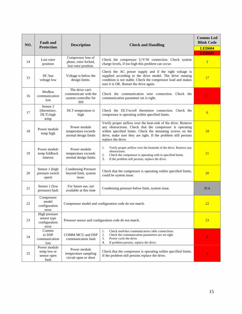
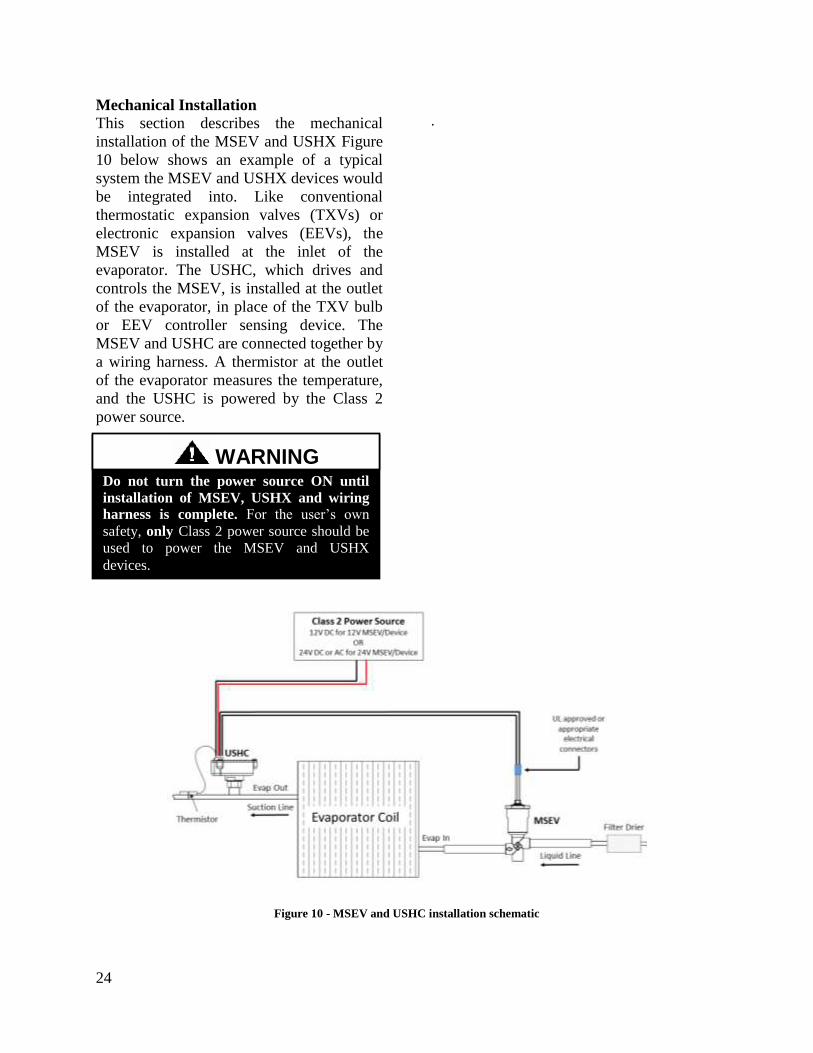