r&s ats-temp user manual the r&s ats‑temp only for its intended use and within its...
TRANSCRIPT
R&S®ATS-TEMPClimate Option for R&S®ATS1000User Manual
User
Man
ual
Versi
on 03
1178727502(;ÜÖÙ2)
This document describes the R&S®ATS-TEMP, order no. 1533.8147.02.
© 2018 Rohde & Schwarz GmbH & Co. KGMühldorfstr. 15, 81671 München, GermanyPhone: +49 89 41 29 - 0Fax: +49 89 41 29 12 164Email: [email protected]: www.rohde-schwarz.comSubject to change – Data without tolerance limits is not binding.R&S® is a registered trademark of Rohde & Schwarz GmbH & Co. KG.Trade names are trademarks of the owners.
1178.7275.02 | Version 03 | R&S®ATS-TEMP
The following abbreviations are used throughout this manual: R&S® is abbreviated as R&S.
ContentsR&S®ATS-TEMP
3User Manual 1178.7275.02 ─ 03
Contents1 Safety Instructions.................................................................................5
1.1 Intended Use..................................................................................................................5
1.2 Requirements for Safe Operation................................................................................5
1.3 How to Prevent Risks................................................................................................... 6
1.4 Safety Labeling..............................................................................................................7
2 Product Description...............................................................................82.1 Key Characteristics.......................................................................................................8
2.2 Delivery........................................................................................................................ 10
2.3 Product Overview........................................................................................................12
3 Putting into Operation......................................................................... 153.1 Test Setup.................................................................................................................... 15
3.2 Connecting to Thermal Air-Stream Device............................................................... 17
3.3 Preparing the DUT.......................................................................................................19
3.4 Calibrating................................................................................................................... 21
4 Performing Measurements..................................................................25
5 Troubleshooting...................................................................................27
Glossary................................................................................................28
Index......................................................................................................30

ContentsR&S®ATS-TEMP
4User Manual 1178.7275.02 ─ 03
Safety InstructionsR&S®ATS-TEMP
5User Manual 1178.7275.02 ─ 03
1 Safety InstructionsSetup and operation of an R&S ATS‑TEMP implies risks of severe injury:
● Burns caused by hot steam● Burns caused by hot surface● Frostbite caused by cold surface● Intoxication caused by toxic fumes● Injury caused by explosion of explosive gases● Risks due to operation of a thermal device● Risks due to operation of the R&S ATS1000 antenna test system
To reduce these risks and prevent accidents, carefully read the following chapters andall related user manuals and safety instructions.
Keep the product documentation in a safe place and pass it on to subsequent users.
1.1 Intended Use
The R&S ATS‑TEMP is intended to be used within the R&S ATS1000 antenna test sys-tem. It allows measurement of RF characteristics of the DUT while exposed to temper-atures between -20 °C to 85 °C.
The climate option for R&S ATS1000 has been manufactured in accordance withaccepted engineering practices and the latest scientific and technical findings. TheR&S ATS‑TEMP has undergone many hours of testing and complies with relevantsafety regulations when operated properly. There are, due to the covered temperaturerange, still dangers involved, even when the product is operated as intended.
1.2 Requirements for Safe Operation
● InstallationMake sure that the R&S ATS‑TEMP is installed into the R&S ATS1000 byRohde & Schwarz personnel, either on site or at the Rohde & Schwarz plant.
● PersonnelMake sure that only personnel familiar with the potential risks of temperature andenvironmental testing operates the R&S ATS‑TEMP.
● Operating AreaEnsure that only personnel familiar with the potential risks of temperature and envi-ronmental testing enters the operating area.Ensure that the operating area is kept free of flammable objects and is tidy.
● OperationEnsure that during operation of the climate option for R&S ATS1000, all safety reg-ulations and operating instructions are adhered to strictly.
Requirements for Safe Operation
Safety InstructionsR&S®ATS-TEMP
6User Manual 1178.7275.02 ─ 03
Observe applicable local or national safety regulations and rules for the preventionof accidents.Ensure that R&S ATS‑TEMP, hoses, and adaptors are well-sealed before operationinside R&S ATS1000.Ensure that the personnel wear protective clothing (work clothes and gloves).Disconnect the DUT from power before touching/removing it from R&S ATS‑TEMP.Use the R&S ATS‑TEMP only for its intended use and within its performance limits.If you are unsure about the appropriate use, contact Rohde & Schwarz service.
● Environmental conditionObserve the operating conditions specified in the data sheet.
● R&S ATS‑TEMP conditionUse the R&S ATS‑TEMP only if it is in excellent condition. If you detect or suspectany irregularities, malfunctions, damage, or temperature leakage; immediately stopusing the R&S ATS‑TEMP and inform Rohde & Schwarz for a service check.
● ModificationsNever change or modify the climate option for R&S ATS1000 or make additionsthat can affect safety.
● Safety stickersDo not remove the safety stickers on the outside of the bottom shell of theR&S ATS‑TEMP. Always keep the stickers visible.If the stickers peel off, you must replace them. Contact Rohde & Schwarz localsupport to order new stickers.
1.3 How to Prevent Risks
How to prevent burns caused by hot steam
When opening the R&S ATS‑TEMP, hot steam can escape and scald you.
To prevent burns:
► Wait until the surface of the dome of R&S ATS‑TEMP is at room temperaturebefore opening and use heat/cold resistant gloves.
How to prevent burns or frostbite caused by hot or cold surface
Depending on operation during extreme temperature testing, the surfaces of theOTA Bubble, mast, hoses, and the DUT can be very hot or very cold. You can sufferfrom burns or frostbite, if you touch these surfaces. Especially, be aware that your fin-gers can freeze to a surface at temperatures below 0° C.
To prevent burns and frostbite:
► Allow the R&S ATS‑TEMP to adjust to room temperature before touching.
► Use heat/cold resistant gloves when touching any hot or cold parts.
How to Prevent Risks
Safety InstructionsR&S®ATS-TEMP
7User Manual 1178.7275.02 ─ 03
How to prevent intoxication and injury due to explosion
When loading the R&S ATS‑TEMP with an unsuitable DUT, toxic or explosive gasescan be produced. These gases can cause the R&S ATS‑TEMP to explode and injureyou. Toxic fumes can escape and lead to intoxication.
To prevent the formation of dangerous gases:
► Load the R&S ATS‑TEMP only with materials/DUTs which do not form any toxic orexplosive vapors when heated up.
How to prevent risk of injury due to operation of a thermal device
Operating a thermal device includes risks of temperature-related injuries.
To prevent these risks:
► Carefully read the safety instructions of the thermal device used.
► Limit the thermal device to the temperature range from -60°C to +105°C.Temperatures outside of this range can damage the equipment and lead to injuries.Note that the R&S ATS‑TEMP and the R&S ATS1000 do not control the thermaldevice. Therefore, temperature limitation is in your responsibility.
1.4 Safety Labeling
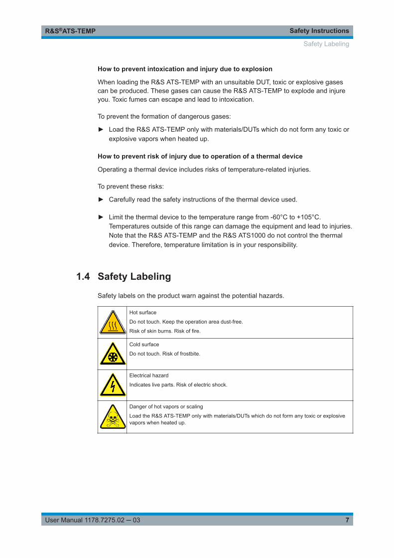
Safety labels on the product warn against the potential hazards.
Hot surface
Do not touch. Keep the operation area dust-free.
Risk of skin burns. Risk of fire.
Cold surface
Do not touch. Risk of frostbite.
Electrical hazard
Indicates live parts. Risk of electric shock.
Danger of hot vapors or scaling
Load the R&S ATS‑TEMP only with materials/DUTs which do not form any toxic or explosivevapors when heated up.
Safety Labeling
Product DescriptionR&S®ATS-TEMP
8User Manual 1178.7275.02 ─ 03
2 Product DescriptionThe R&S ATS‑TEMP is a climate option for R&S ATS1000. This Rohde & Schwarzproduct allows 3D RF measurements of antenna characteristics in a temperature rangefrom -20 °C to 85 °C to analyze temperature effect on the chipset and UE performance.The provided measurement conditions are suitable for tests at extreme temperaturesand extreme temperature ranges.
The R&S ATS‑TEMP operates mounted in an antenna test system R&S ATS1000. Acurrent version of R&S ATS1000, which has a false-floor plate with predefined holes init, supports the climate option for R&S ATS1000. A retrofit of an older R&S ATS1000chamber to this thermal solution must be performed by Rohde & Schwarz service.
The R&S ATS‑TEMP is designed for operation with thermal test device to be connec-ted to the hose adaptors of the R&S ATS‑TEMP. The thermal test device uses hot orcold airstream. It controls the temperature via its temperature sensors placed in theR&S ATS1000 chamber.
Rohde & Schwarz recommends the thermal device TA-5000A to be used withR&S ATS‑TEMP. With this thermal test device, all connectors match.
This user manual contains a description of the functionality that the R&S ATS‑TEMPprovides. The latest version is available for download at the product homepage(www.rohde-schwarz.com/product/ats1000).
2.1 Key Characteristics
The R&S ATS‑TEMP consists of an RF transparent material which minimizes the influ-ence to the radiated measurements (< -1dB for 5G NR for 22 GHz to 45 GHz). Due toits compact design, the R&S ATS‑TEMP results in fast and precise 3D measurementswith excellent repeatability and angular resolution.
The key characteristics of the R&S ATS‑TEMP are the following:
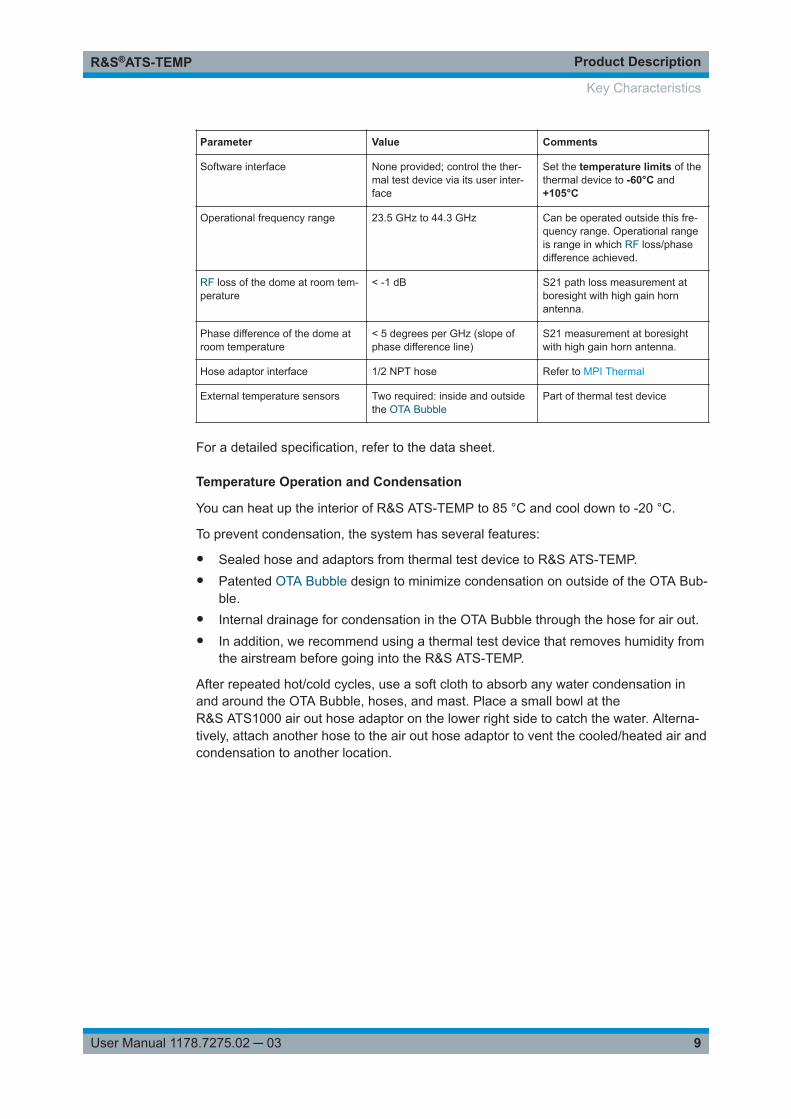
Table 2-1: Specification
Parameter Value Comments
Outer dimensions 30 cm Diameter
Inner dimensions (max. DUT size) 22 cm x 22 cm
Operational temperature range -20 °C to 85 °C Possible to go to -40 °C for shortperiods (less than five minutes)
Minimum soak time for extremetemperatures before cooling/heat-ing cycle
3 minutes
Maximum soak time for extremetemperatures
Dependent on the temperatureoutside R&S ATS‑TEMP
If the ambient temperature out-side R&S ATS‑TEMP is above40 °C, perform a cold temperaturecycle to cool the OTA Bubble.
Key Characteristics
Product DescriptionR&S®ATS-TEMP
9User Manual 1178.7275.02 ─ 03
Parameter Value Comments
Software interface None provided; control the ther-mal test device via its user inter-face
Set the temperature limits of thethermal device to -60°C and+105°C
Operational frequency range 23.5 GHz to 44.3 GHz Can be operated outside this fre-quency range. Operational rangeis range in which RF loss/phasedifference achieved.
RF loss of the dome at room tem-perature
< -1 dB S21 path loss measurement atboresight with high gain hornantenna.
Phase difference of the dome atroom temperature
< 5 degrees per GHz (slope ofphase difference line)
S21 measurement at boresightwith high gain horn antenna.
Hose adaptor interface 1/2 NPT hose Refer to MPI Thermal
External temperature sensors Two required: inside and outsidethe OTA Bubble
Part of thermal test device
For a detailed specification, refer to the data sheet.
Temperature Operation and Condensation
You can heat up the interior of R&S ATS‑TEMP to 85 °C and cool down to -20 °C.
To prevent condensation, the system has several features:
● Sealed hose and adaptors from thermal test device to R&S ATS‑TEMP.● Patented OTA Bubble design to minimize condensation on outside of the OTA Bub-
ble.● Internal drainage for condensation in the OTA Bubble through the hose for air out.● In addition, we recommend using a thermal test device that removes humidity from
the airstream before going into the R&S ATS‑TEMP.
After repeated hot/cold cycles, use a soft cloth to absorb any water condensation inand around the OTA Bubble, hoses, and mast. Place a small bowl at theR&S ATS1000 air out hose adaptor on the lower right side to catch the water. Alterna-tively, attach another hose to the air out hose adaptor to vent the cooled/heated air andcondensation to another location.
Key Characteristics
Product DescriptionR&S®ATS-TEMP
10User Manual 1178.7275.02 ─ 03
2.2 Delivery
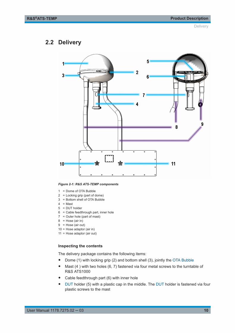
Figure 2-1: R&S ATS‑TEMP components
1 = Dome of OTA Bubble2 = Locking grip (part of dome)3 = Bottom shell of OTA Bubble4 = Mast5 = DUT holder6 = Cable feedthrough part, inner hole7 = Outer hole (part of mast)8 = Hose (air in)9 = Hose (air out)10 = Hose adaptor (air in)11 = Hose adaptor (air out)
Inspecting the contents
The delivery package contains the following items:● Dome (1) with locking grip (2) and bottom shell (3), jointly the OTA Bubble● Mast (4 ) with two holes (6, 7) fastened via four metal screws to the turntable of
R&S ATS1000● Cable feedthrough part (6) with inner hole● DUT holder (5) with a plastic cap in the middle. The DUT holder is fastened via four
plastic screws to the mast
Delivery
Product DescriptionR&S®ATS-TEMP
11User Manual 1178.7275.02 ─ 03
● Air hoses (8, 9) connected to the OTA Bubble via bayonet thread.● Plate with hose adaptors (10, 11), 1/2 NPT female connectors (diameter 40 mm),
possible opening for temperature sensors● User manual
Inspect the package for damage
Keep the package and the cushioning material until the contents have been checkedfor completeness and the device has been tested.
If the packaging material shows any signs of stress, notify the carrier and yourRohde & Schwarz service center. Keep the damaged package and cushioning materialfor inspection.
Inspect the product
If the content is incomplete, damaged, or defect or if the R&S ATS‑TEMP climateoption for R&S ATS1000 does not operate properly, notify your Rohde & Schwarz ser-vice center.
Calibration certificate
The calibration certificate is not included in the standard shipping. The calibration isdescribed in Chapter 3.4, "Calibrating", on page 21.
Additional equipment
The following required equipment is not included in the order number of anR&S ATS‑TEMP. It must be also ordered:● R&S ATS1000
Rohde & Schwarz delivers the R&S ATS‑TEMP mounted in an R&S ATS1000.Only the service personnel of Rohde & Schwarz is authorized to retrofit the formerversions of R&S ATS1000 to support the R&S ATS‑TEMP.To mount the R&S ATS‑TEMP into the R&S ATS1000 or to remove it from theR&S ATS1000, contact Rohde & Schwarz service.
● Thermal test device with hoses and two external temperature sensors:Rohde & Schwarz recommends TA-5000A to be used with R&S ATS‑TEMP. Withthis thermal test device, all connectors match.
● Measurement instruments:– Signal analyzer (for example, R&S ZVA or R&S FSW ) for DUT transceiver
measurements: channel power, EVM, ACLR, SEM, etc.– Signal generator (for example R&S SMW200) for passive DUT measurements.
● R&S OSP:Switch box for automated/controlled switching between measurement instruments.
● Cables to the DUT for charging, RF connection, control IF, etc., if necessary.
Delivery
Product DescriptionR&S®ATS-TEMP
12User Manual 1178.7275.02 ─ 03
2.3 Product Overview
The R&S ATS‑TEMP consists of the following components:
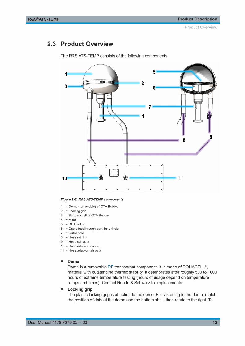
Figure 2-2: R&S ATS‑TEMP components
1 = Dome (removable) of OTA Bubble2 = Locking grip3 = Bottom shell of OTA Bubble4 = Mast5 = DUT holder6 = Cable feedthrough part, inner hole7 = Outer hole8 = Hose (air in)9 = Hose (air out)10 = Hose adaptor (air in)11 = Hose adaptor (air out)
● DomeDome is a removable RF transparent component. It is made of ROHACELL®,material with outstanding thermic stability. It deteriorates after roughly 500 to 1000hours of extreme temperature testing (hours of usage depend on temperatureramps and times). Contact Rohde & Schwarz for replacements.
● Locking gripThe plastic locking grip is attached to the dome. For fastening to the dome, matchthe position of dots at the dome and the bottom shell, then rotate to the right. To
Product Overview
Product DescriptionR&S®ATS-TEMP
13User Manual 1178.7275.02 ─ 03
loosen and remove the dome, rotate to the left. Do not remove the locking gripfrom the dome.
● Bottom shellThe bottom shell is a static component. It houses the rotating DUT holder andlocks the dome during the tests.Ensure that warning stickers placed at the bottom shell are always visible and hee-ded during and after operation.
● MastThe mast is connected to the R&S ATS1000 turntable with four metal screws.Wear heat resistant gloves when touching the metal screws after an extreme tem-perature testing.The mast rotates during tests. For precise rotation of positioner, keep temperaturein this area below 40 °C. If necessary, add additional insulation into the mast toprevent overheating.
● DUT holderThe DUT holder is drilled, to provide many possibilities to fasten the DUT. Use onlyplastic screws or bolts to fasten the DUT. Metal screws influence and corrupt themeasurement results. Use a plastic cap in the middle, to avoid temperature loses.The holder rotates during tests.
● Cable feedthrough part and inner holeThe cable feedthrough part with a hole (matching with the upper hole in the mast)for cabling to the DUT
● Outer holeLower hole in the wall of mast for cables to the DUT. Preferably, use the innerspace of the mast tube to conduct cables through to the DUT.This section can become very hot or very cold immediately after testing. Avoidtouching this area until the DUT and R&S ATS1000 have cooled down to ambienttemperature.
● Air in hoseHose from the thermal test device hose adaptor (air in) into the OTA Bubble. Becareful touching the section of the hose entering into the OTA Bubble as this jointcan get very hot or very cold during and immediately after extreme temperaturetesting.To fasten, rotate the hose in counterclockwise direction. To loosen, rotate the hosein clockwise direction.
● Air out hoseHose from the OTA Bubble to the R&S ATS1000 hose adaptor (air out). Be carefultouching the section of the hose exiting the OTA Bubble as this joint can get veryhot or very cold during and immediately after extreme temperature testing.To fasten, rotate the hose in counterclockwise direction. To loosen, rotate the hosein clockwise direction.
● Plate with hose adaptorsThe plate on the lower left side of the R&S ATS1000 is equipped with:– Hose adaptors (10, 11) - 1/2 NPT female connectors of diameter 40 mm - and– A rectangle cover plate for feedthrough of temperature sensors
Product Overview
Product DescriptionR&S®ATS-TEMP
14User Manual 1178.7275.02 ─ 03
Hose adaptor (10) is used to connect a thermal test device via a hose (air in) to theOTA Bubble. Be careful touching the metal hose adaptor as this joint can get veryhot or very cold during and immediately after extreme temperature testing.Hose adaptor (11) between the air out hose from the OTA Bubble to the outside ofthe OTA Bubble. If necessary, place a container here to catch condensation, orattach another hose to ventilate the air to another location.
Product Overview
Putting into OperationR&S®ATS-TEMP
15User Manual 1178.7275.02 ─ 03
3 Putting into OperationThe R&S ATS‑TEMP climate option for R&S ATS1000 has been designed to withstanda moderate amount of physical and temperature stress. Treat the product with care. Itcan be damaged if excessive force is applied.
Risk of instrument damage due to mechanical shockExercise care to prevent the product from receiving mechanical shock.Always handle the product by the delivered hoses.Avoid putting excessive strain on the product or exposing it to sharp bends.
During operation, the product heats up. This behavior is normal and not a sign of mal-function.
The following topics are covered in the next sections:
● Test Setup............................................................................................................... 15● Connecting to Thermal Air-Stream Device..............................................................17● Preparing the DUT.................................................................................................. 19● Calibrating...............................................................................................................21
3.1 Test Setup
The following figure shows the test setup for testing under extreme temperature condi-tions with R&S ATS‑TEMP, including additional required equipment.
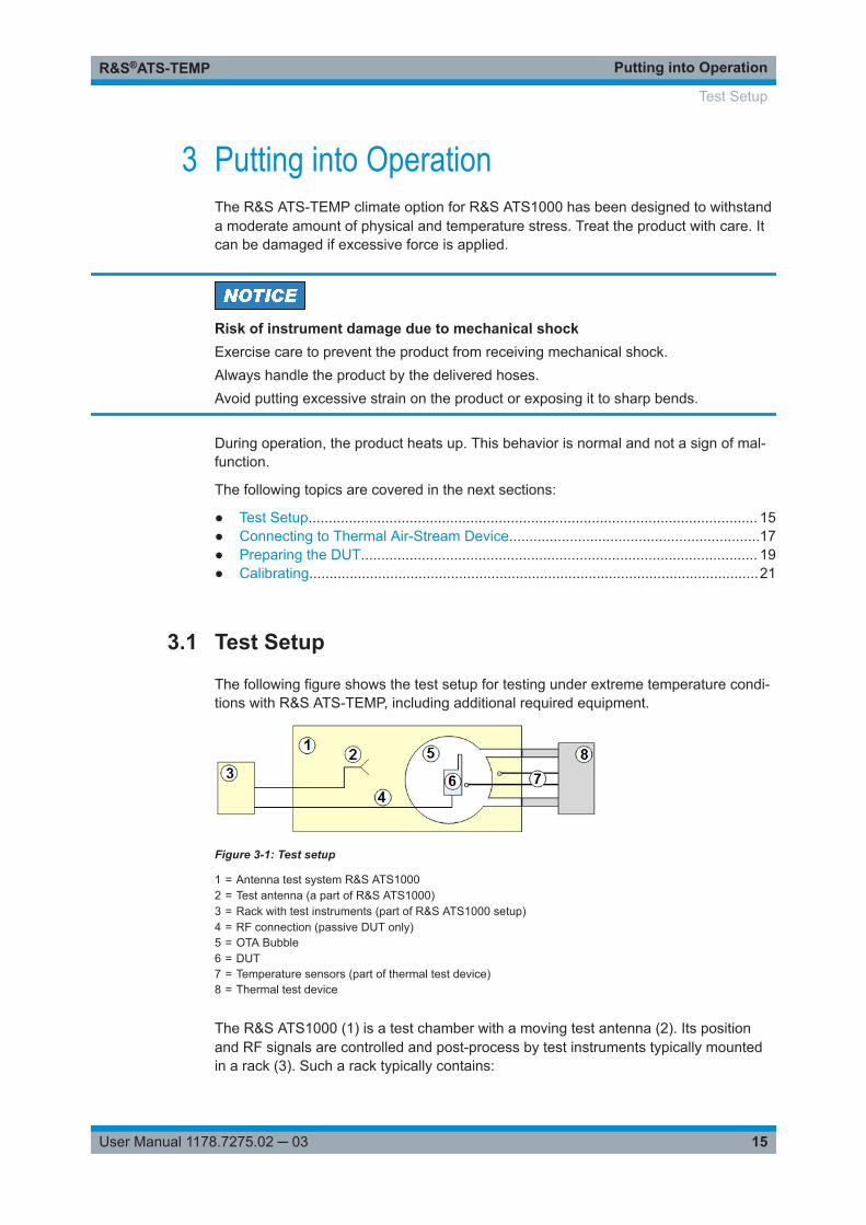
Figure 3-1: Test setup
1 = Antenna test system R&S ATS10002 = Test antenna (a part of R&S ATS1000)3 = Rack with test instruments (part of R&S ATS1000 setup)4 = RF connection (passive DUT only)5 = OTA Bubble6 = DUT7 = Temperature sensors (part of thermal test device)8 = Thermal test device
The R&S ATS1000 (1) is a test chamber with a moving test antenna (2). Its positionand RF signals are controlled and post-process by test instruments typically mountedin a rack (3). Such a rack typically contains:
Test Setup
Putting into OperationR&S®ATS-TEMP
16User Manual 1178.7275.02 ─ 03
● Antenna positioning controller Maturo NCD● Measuring receiver as
– Signal and spectrum analyzer (for example R&S FSW) or– Vector network analyzer (for example R&S ZVA)
● Vector signal generator for (for example R&S SMW200) used for an RF connection(4) to feed a passive DUT
● Switch unit (for example R&S OSP) for automated/controlled switching betweenmeasurement instruments
The R&S ATS‑TEMP (5) is an RF transparent thermal chamber (OTA Bubble). It canbe easily mounted into the R&S ATS1000 (1). It stabilizes a rotating DUT (6) for 3Dmeasurements and contains thermal hoses for air circulation between theR&S ATS‑TEMP and a thermal test device (8). The thermal test device controls testtemperature cycles. The R&S ATS‑TEMP enables the thermal test device to placeexternal temperature sensors (7) inside and outside the OTA Bubble.
There are two recommended setups for R&S ATS‑TEMP:
● Device Cooling Test Setup......................................................................................16● High Temperatures Test Setup................................................................................17
3.1.1 Device Cooling Test Setup
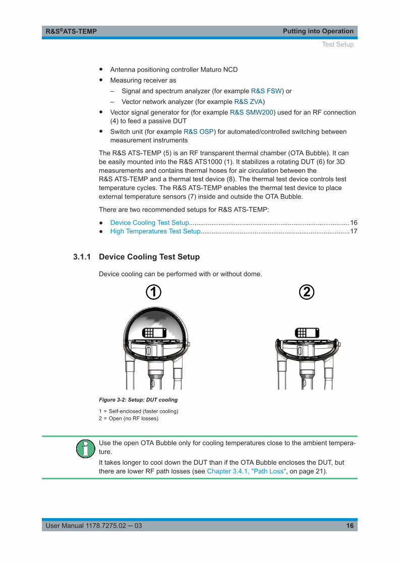
Device cooling can be performed with or without dome.
Figure 3-2: Setup: DUT cooling
1 = Self-enclosed (faster cooling)2 = Open (no RF losses)
Use the open OTA Bubble only for cooling temperatures close to the ambient tempera-ture.It takes longer to cool down the DUT than if the OTA Bubble encloses the DUT, butthere are lower RF path losses (see Chapter 3.4.1, "Path Loss", on page 21).
Test Setup
Putting into OperationR&S®ATS-TEMP
17User Manual 1178.7275.02 ─ 03
For a detailed description of R&S ATS‑TEMP components, see Chapter 2.3, "ProductOverview", on page 12.
For a list of additional equipment, see Chapter 3.1, "Test Setup", on page 15.
3.1.2 High Temperatures Test Setup
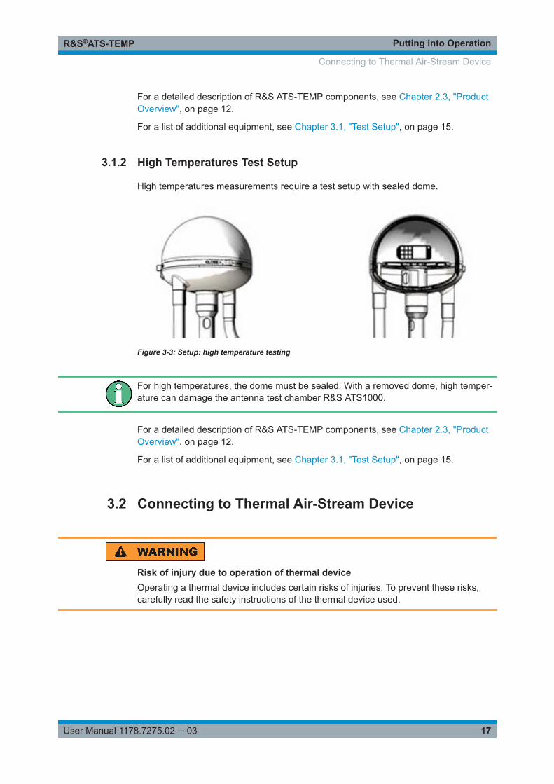
High temperatures measurements require a test setup with sealed dome.
Figure 3-3: Setup: high temperature testing
For high temperatures, the dome must be sealed. With a removed dome, high temper-ature can damage the antenna test chamber R&S ATS1000.
For a detailed description of R&S ATS‑TEMP components, see Chapter 2.3, "ProductOverview", on page 12.
For a list of additional equipment, see Chapter 3.1, "Test Setup", on page 15.
3.2 Connecting to Thermal Air-Stream Device
Risk of injury due to operation of thermal deviceOperating a thermal device includes certain risks of injuries. To prevent these risks,carefully read the safety instructions of the thermal device used.
Connecting to Thermal Air-Stream Device
Putting into OperationR&S®ATS-TEMP
18User Manual 1178.7275.02 ─ 03
Risk of equipment damage due to extreme temperatures of thermal devicesDepending on the thermal test device that you use, the device's temperature limitscan be far outside of the specified temperature range for the R&S ATS‑TEMP. Forexample, the temperature range of the TA-5000A is -100 °C to +300 °C.Exposing the R&S ATS‑TEMP and the R&S ATS1000 to these extreme temperaturescan damage your equipment. For example, polymer materials in your equipment canmelt.Note that the R&S ATS‑TEMP and the R&S ATS1000 do not control the temperaturelimits of any external thermal device.To avoid the risk of damage, make sure to limit the output temperatures of the ther-mal test device to the range from -60 °C to +105 °C. These settings allow operating theR&S ATS‑TEMP in its specified temperature range from -20 °C to +85 °C (and down to-40 °C for <5 minutes).
There are several thermal test devices on the market.
Recommendation for features of thermal air-stream device:● Operating temperature range at least -60 °C to 105 °C● Automated temperature cycling● Temperature control via at least two temperature sensors● Frost-free test environment via dry air (nominal humidity 45%)
Rohde & Schwarz recommends the thermal device TA-5000A to be used withR&S ATS‑TEMP. With this thermal test device, all connectors match.
To connect the TA-5000A to the R&S ATS‑TEMP, proceed as follows:
1. To connect the flexible air hoses of the TA-5000A via bayonet thread to the hoseadaptors, push and rotate to the right.
2. Remove the rectangle cover plate from the plate with hose adaptors.
3. Conduct two temperature sensors (labeled (7) in Figure 3-1) through the rectangu-lar opening in the plate with hose adaptors.
4. Leave one sensor at the bottom of R&S ATS1000 near the mast.If you use the TA-5000A, select temperature sensor "T" for this position.
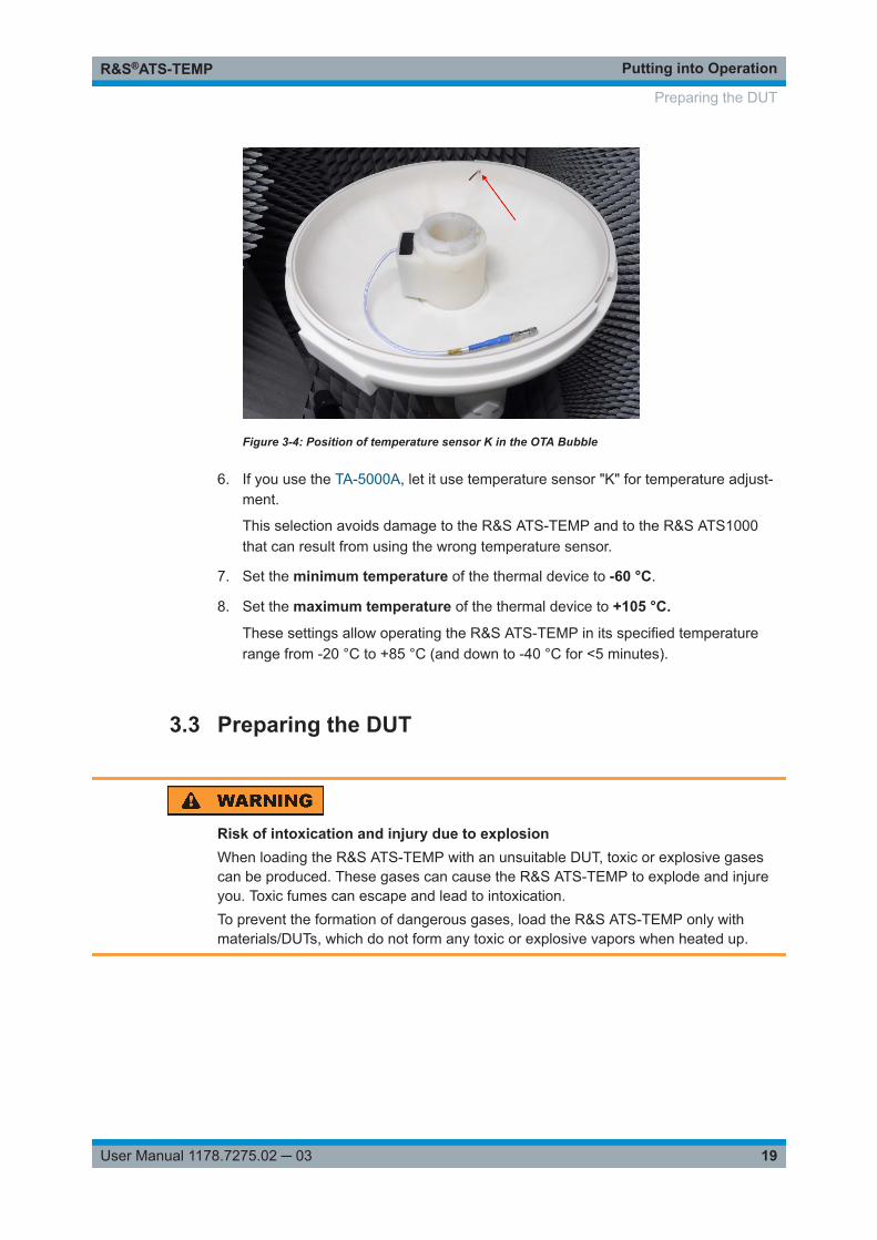
5. Conduct another temperature sensor through the opening in the bottom shell allthe way up into the OTA Bubble (red arrow in Figure 3-4).If you use the TA-5000A, select temperature sensor "K" for this position.
Connecting to Thermal Air-Stream Device
Putting into OperationR&S®ATS-TEMP
19User Manual 1178.7275.02 ─ 03
Figure 3-4: Position of temperature sensor K in the OTA Bubble
6. If you use the TA-5000A, let it use temperature sensor "K" for temperature adjust-ment.
This selection avoids damage to the R&S ATS‑TEMP and to the R&S ATS1000that can result from using the wrong temperature sensor.
7. Set the minimum temperature of the thermal device to -60 °C.
8. Set the maximum temperature of the thermal device to +105 °C.
These settings allow operating the R&S ATS‑TEMP in its specified temperaturerange from -20 °C to +85 °C (and down to -40 °C for <5 minutes).
3.3 Preparing the DUT
Risk of intoxication and injury due to explosionWhen loading the R&S ATS‑TEMP with an unsuitable DUT, toxic or explosive gasescan be produced. These gases can cause the R&S ATS‑TEMP to explode and injureyou. Toxic fumes can escape and lead to intoxication.To prevent the formation of dangerous gases, load the R&S ATS‑TEMP only withmaterials/DUTs, which do not form any toxic or explosive vapors when heated up.
Preparing the DUT
Putting into OperationR&S®ATS-TEMP
20User Manual 1178.7275.02 ─ 03
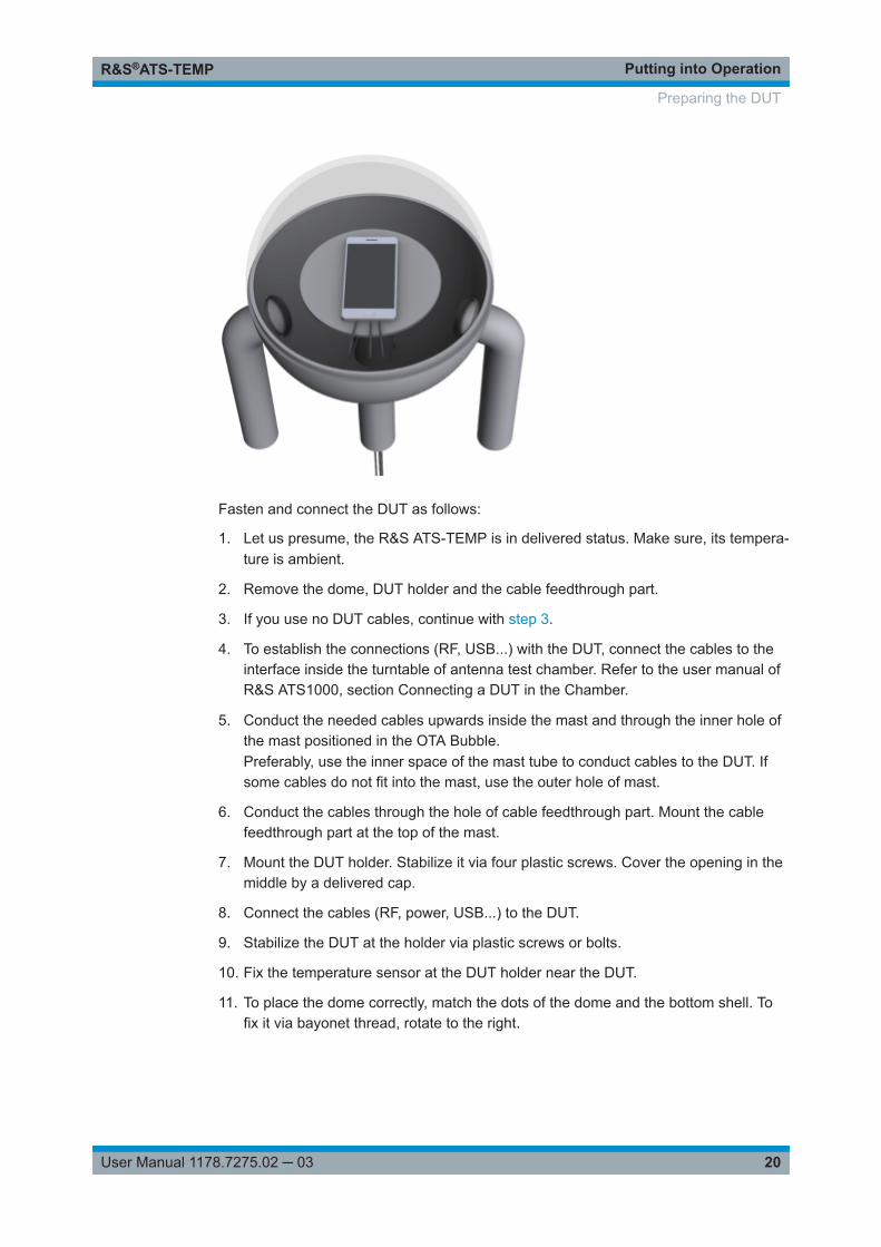
Fasten and connect the DUT as follows:
1. Let us presume, the R&S ATS‑TEMP is in delivered status. Make sure, its tempera-ture is ambient.
2. Remove the dome, DUT holder and the cable feedthrough part.
3. If you use no DUT cables, continue with step 3.
4. To establish the connections (RF, USB...) with the DUT, connect the cables to theinterface inside the turntable of antenna test chamber. Refer to the user manual ofR&S ATS1000, section Connecting a DUT in the Chamber.
5. Conduct the needed cables upwards inside the mast and through the inner hole ofthe mast positioned in the OTA Bubble.Preferably, use the inner space of the mast tube to conduct cables to the DUT. Ifsome cables do not fit into the mast, use the outer hole of mast.
6. Conduct the cables through the hole of cable feedthrough part. Mount the cablefeedthrough part at the top of the mast.
7. Mount the DUT holder. Stabilize it via four plastic screws. Cover the opening in themiddle by a delivered cap.
8. Connect the cables (RF, power, USB...) to the DUT.
9. Stabilize the DUT at the holder via plastic screws or bolts.
10. Fix the temperature sensor at the DUT holder near the DUT.
11. To place the dome correctly, match the dots of the dome and the bottom shell. Tofix it via bayonet thread, rotate to the right.
Preparing the DUT
Putting into OperationR&S®ATS-TEMP
21User Manual 1178.7275.02 ─ 03
3.4 Calibrating
There are two types of calibration required for proper use of R&S ATS‑TEMP:
● RF calibration is a conventional path loss measurement to quantify the effect ofthe R&S ATS‑TEMP as a function of frequency.See Chapter 3.4.1, "Path Loss", on page 21.
● Thermal calibration is a new type of OTA calibration. It requires an external tem-perature reference to calibrate the temperature sensors purchased separately inaddition to the temperature effects on cables for passive measurements.See Chapter 3.4.2, "Temperature Calibration", on page 23.
For calibration purposes, it is assumed that all RF signals are continuous wave (CW)or swept frequency.
3.4.1 Path Loss
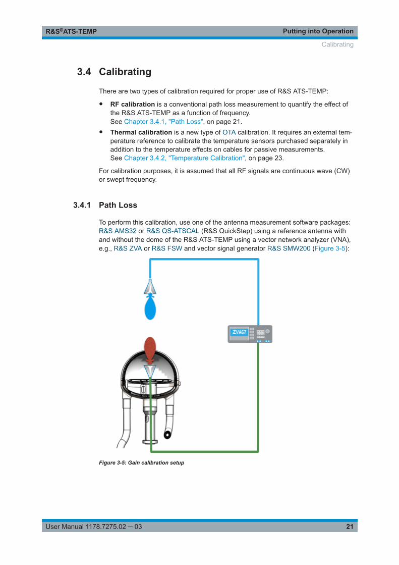
To perform this calibration, use one of the antenna measurement software packages:R&S AMS32 or R&S QS-ATSCAL (R&S QuickStep) using a reference antenna withand without the dome of the R&S ATS‑TEMP using a vector network analyzer (VNA),e.g., R&S ZVA or R&S FSW and vector signal generator R&S SMW200 (Figure 3-5):
Figure 3-5: Gain calibration setup
Calibrating
Putting into OperationR&S®ATS-TEMP
22User Manual 1178.7275.02 ─ 03
1. Place the reference horn at the center of the DUT holder inside theR&S ATS‑TEMP.Direct the main antenna aperture upwards, toward the measurement antenna (inthe boresight of the antennas).
2. To remove the dome of R&S ATS‑TEMP, first rotate the dome by locking grip to theleft.
3. Connect the VNA as follows:
● Connect one port of the VNA via RF cable to the reference antenna at the DUTholder.
● Connect the second (and third) port to the first (second) polarization of an RFtest antenna at the top of the elevation arm.
4. Perform a S21 (and S31 for second polarization) measurement of amplitude overthe desired frequency range.
5. Store the data into a file.
6. Place the dome of R&S ATS‑TEMP matching two dots at the bottom shell and thedome.
The reference antenna is inside the OTA Bubble.
7. To lock the dome, rotate it to the right.
8. Repeat step 4.
9. Store the data into the S21... (S31...) calibration log file.The difference between the two measurements is the amplitude calibration coeffi-cient.
10. Use the calibration log file S21... (S31...) in a measurement receiver (VNA), tocompensate the error.
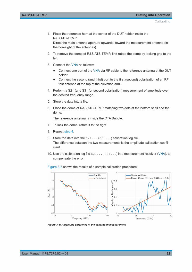
Figure 3-6 shows the results of a sample calibration procedure:
Figure 3-6: Amplitude difference in the calibration measurement
Calibrating
Putting into OperationR&S®ATS-TEMP
23User Manual 1178.7275.02 ─ 03
Left chart, blue line = Measured magnitude with OTA Bubble in placeLeft chart, red line = Measured magnitude without OTA BubbleRight chart, blue line = Magnitude deviation (dB), measured difference with/without OTA BubbleRight chart, red line = Linear curve fit: y = 0.045 * x - 1.14
3.4.2 Temperature Calibration
Risk of burns caused by hot steam or hot surfaceDuring extreme temperature testing, the surfaces of the OTA Bubble, mast, hoses, andthe DUT can be very hot. You can suffer from burns if you touch these surfaces.To prevent burns, allow the R&S ATS‑TEMP to adjust to room temperature beforetouching.When opening the R&S ATS‑TEMP, hot steam can escape and scald you. To preventinjury, wait until the surface of the dome of R&S ATS‑TEMP is at room temperaturebefore opening. Use heat resistant gloves when touching any hot parts.
For passive measurements using Teflon-based cables, perform a temperature calibra-tion, due to the different electrical length and attenuation of the Teflon-based cable indifferent temperature conditions.
We recommend keeping the cable inside the R&S ATS‑TEMP as short as possible.
For calibration measurements, use R&S AMS32, R&S CONTEST, or R&S QS-ATS-CAL (R&S QuickStep).
1. Place the reference horn at the center of the DUT holder inside R&S ATS‑TEMP.Direct the main antenna aperture upwards, toward the measurement antenna (inthe boresight of the antennas).
2. Connect the VNA as follows:
● Connect one port to the reference antenna fixed at the DUT holder.● Connect the second port (third port) to the vertically polarized test antenna (to
the horizontally polarized test antenna) at the top of the elevation arm.
3. Place the first temperature sensor of the thermal test device into the OTA Bubble,near the DUT.
4. Place the second temperature sensor outside the OTA Bubble, near the base ofthe mast.
5. Set the following values on thermal test device:● Room temperature: 25 °C● Soak time: 5 minutes● Flow rate: 10 CF
Calibrating
Putting into OperationR&S®ATS-TEMP
24User Manual 1178.7275.02 ─ 03
6. Perform a S21 (and S31 for dual-port measurement antenna) measurement ofamplitude over the desired frequency range after 1or 2 minutes of the soak time.
7. Store the data into the S21Temp25 file.
8. Set temperature points corresponding to the desired temperatures with 5 minutessoak times.
9. Repeat step 6 for each temperature.
10. Store the data into the S21TempX file.The difference between the two measurements is the amplitude calibration coeffi-cient.
Calibrating
Performing MeasurementsR&S®ATS-TEMP
25User Manual 1178.7275.02 ─ 03
4 Performing Measurements
Risk of burns caused by hot steam or hot surfaceDuring extreme temperature testing, the surfaces of the OTA Bubble, mast, hoses, andthe DUT can be very hot. You can suffer from burns if you touch these surfaces.To prevent burns, allow the R&S ATS‑TEMP to adjust to room temperature beforetouching.When opening the R&S ATS‑TEMP, hot steam can escape and scald you. To preventinjury, wait until the surface of the dome of R&S ATS‑TEMP is at room temperaturebefore opening. Use heat resistant gloves when touching any hot parts.
Risk of frostbite caused by cold surfaceDuring extreme temperature testing, the surfaces of the OTA Bubble, mast, and hosescan be very cold. You can suffer from frostbite if you touch these surfaces. Especially,be aware that your fingers can freeze to a surface at temperatures below 0° C.To prevent frostbite, allow the R&S ATS‑TEMP to adjust to room temperature beforetouching. Use cold resistant gloves when touching any cold parts.
In this chapter, measurements are segmented according to the type of DUT: passive oractive. For simplicity, even if an R&S OSP switch and control unit is used, this manualassumes a direct connection to the measurement instruments.
● A passive DUT is defined as an RF-cable fed DUT where one/two ports are con-nected to a VNA. The other two ports are connected to the measurement antennaat the end of the elevation arm inside R&S ATS1000. Due to the temperaturedependency of the cable attenuation and phase on temperature, perform first theR&S ATS‑TEMP and temperature calibrations.
● An active DUT is defined as a DUT with an internal RF transceiver that can gener-ate and/or receive RF signals that can be continuous wave (CW) or modulated sig-nals. An RF-cable is not part of this setup and only a R&S ATS‑TEMP calibration isnecessary before measurements.
The remaining measurement steps are the same for both passive and active DUTs.
For measurements, perform the following steps:
1. Place the DUT at the center of the DUT holder inside the R&S ATS‑TEMP, so thatthe antenna aperture is in the center of the quiet zone (for far-field measurements).
2. Connect the measurement equipment:
● Passive: VNA, as described in Chapter 3.4.2, "Temperature Calibration",on page 23.
Performing MeasurementsR&S®ATS-TEMP
26User Manual 1178.7275.02 ─ 03
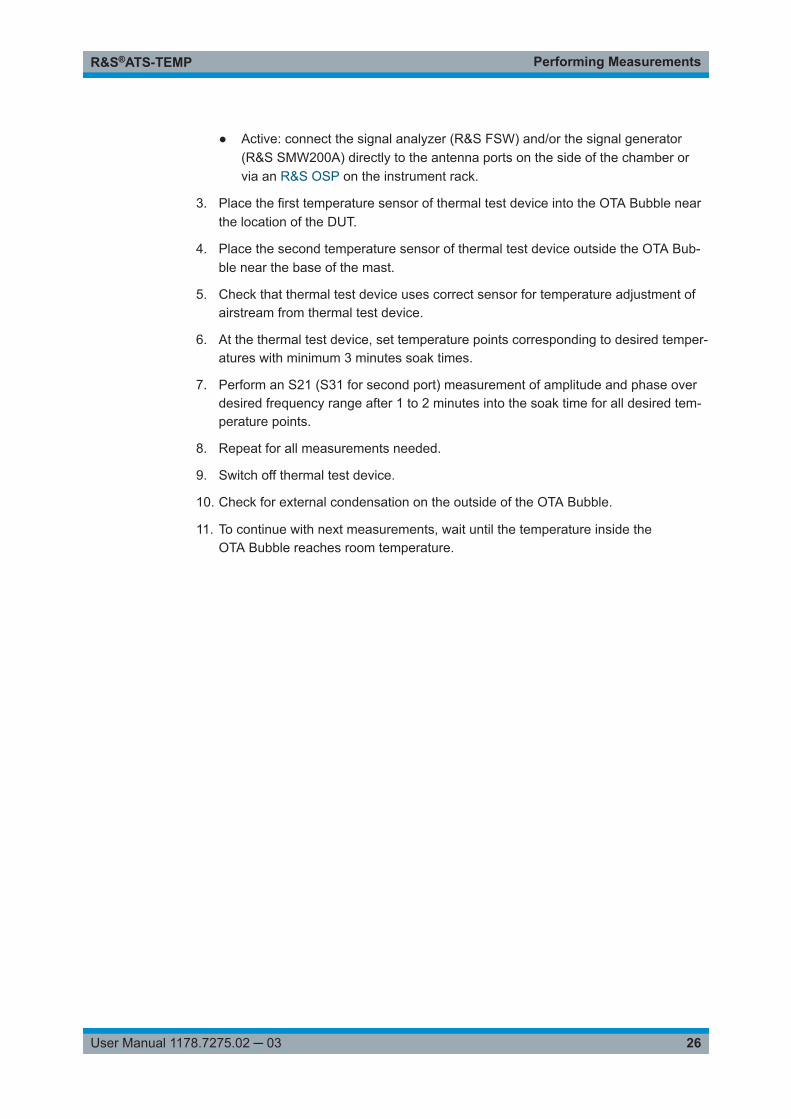
● Active: connect the signal analyzer (R&S FSW) and/or the signal generator(R&S SMW200A) directly to the antenna ports on the side of the chamber orvia an R&S OSP on the instrument rack.
3. Place the first temperature sensor of thermal test device into the OTA Bubble nearthe location of the DUT.
4. Place the second temperature sensor of thermal test device outside the OTA Bub-ble near the base of the mast.
5. Check that thermal test device uses correct sensor for temperature adjustment ofairstream from thermal test device.
6. At the thermal test device, set temperature points corresponding to desired temper-atures with minimum 3 minutes soak times.
7. Perform an S21 (S31 for second port) measurement of amplitude and phase overdesired frequency range after 1 to 2 minutes into the soak time for all desired tem-perature points.
8. Repeat for all measurements needed.
9. Switch off thermal test device.
10. Check for external condensation on the outside of the OTA Bubble.
11. To continue with next measurements, wait until the temperature inside theOTA Bubble reaches room temperature.
TroubleshootingR&S®ATS-TEMP
27User Manual 1178.7275.02 ─ 03
5 Troubleshooting● General remarks
We recommend performing regular checkups of the system thermal propertiesusing an external temperature sensor at non-extreme temperatures.
● If the system is taking longer than usual to reach desired temperatures– Check the flow rate on thermal test device. We recommend a flow rate of
10 CF, maximum 12 CF.– Check for any thermal leakage on the dome. If there are obvious signs of dete-
rioration (cracks in the surface, brittle surface when touched), call aRohde & Schwarz sales representative to replace the dome.
– Check for any thermal leakage at the hose / OTA Bubble / antenna test cham-ber interface. If there is a leakage, tighten the hose. Otherwise callRohde & Schwarz service for repair.
● If there are visible signs of thermal damage on the OTA BubbleCall Rohde & Schwarz sales for a dome replacement.
● If there is condensation outside the OTA BubbleCondensation is expected in particularly hot and humid climates. We recommendoperating R&S ATS‑TEMP in a temperature and humidity-controlled lab.If there is still condensation, use a cloth to absorb the water. Run thenR&S ATS‑TEMP through several hot-cold iterations (without DUT) to remove thehumidity from the air before performing DUT measurements.
GlossaryR&S®ATS-TEMP
28User Manual 1178.7275.02 ─ 03
GlossaryA
ACLR: adjacent channel leakage ratio
CCW: continuous wave
DDUT: device under test
EEVM: error vector magnitude
OOTA: over the air
OTA Bubble: RF transparent, oval-shaped thermal chamber of the R&S ATS‑TEMP
RR&S AMS32: Rohde & Schwarz measurement software (part of R&S EMC32 soft-ware), refer to www.rohde-schwarz.com/product/emc32
R&S ATS1000: Rohde & Schwarz antenna test system,refer to www.rohde-schwarz.com/product/ats1000
R&S CONTEST: Rohde & Schwarz application software
R&S FSW: Rohde & Schwarz signal and spectrum analyzer,refer to www.rohde-schwarz.com/product/fsw
R&S OSP: Rohde & Schwarz open switch and control platform,refer to www.rohde-schwarz.com/product/osp
R&S QS-ATSCAL: Rohde & Schwarz automatic calibration of R&S ATS1000 and posi-tioner driver (part of R&S QuickStep software),refer to www.rohde-schwarz.com/product/quickstep
R&S SMW200: Rohde & Schwarz vector signal generator,refer to www.rohde-schwarz.com/product/smw200
R&S ZVA: Rohde & Schwarz vector network analyzer,refer to www.rohde-schwarz.com/product/zva
GlossaryR&S®ATS-TEMP
29User Manual 1178.7275.02 ─ 03
RF: radio frequency
SSEM: spectral emission mask
TTA-5000A: temperature testing system ThermalAir 5000A, refer to MPI Thermal
VVNA: vector network analyzer
IndexR&S®ATS-TEMP
30User Manual 1178.7275.02 ─ 03
Index
C
Calibration ......................................................................... 11Path loss ..................................................................... 21Temperature ................................................................23
Characteristics .................................................................... 8Connecting to DUT ............................................................19Cooling .............................................................................. 16
D
Dome (removable) ........................................................ 6, 12DUT ............................................................................... 6, 19
H
Heating .............................................................................. 17
L
Labels ..................................................................................7Locking grip ....................................................................... 12
M
MeasurementsActive DUT ..................................................................25Passive DUT ............................................................... 25
O
OTA Bubble ....................................................................... 10
P
Path loss calibration .......................................................... 21
R
RisksBurns ............................................................................ 6Explosion ...................................................................... 7Frostbite ........................................................................ 6Intoxication ....................................................................7Thermal air-stream device ............................................ 7
S
Safety .................................................................................. 5Labels ........................................................................... 7
Setup ................................................................................. 15Device cooling ............................................................ 16Extreme temperatures ................................................ 17
Specification ........................................................................ 8
T
Temperature calibration .....................................................23Thermal air-stream device ............................................ 7, 17
U
Unpacking ......................................................................... 10