r&s smw-k50/-k51 td-scdma, incl. td-scdma · pdf filer&s®smw-k50/-k51 td-scdma,...
TRANSCRIPT
R&S®SMW-K50/-K51TD-SCDMA, incl. TD-SCDMAEnhanced FeaturesUser Manual
User
Man
ual
1175.6761.02 ─ 11(;ÙÑË2)
This document describes the following software options:
● R&S®SMW-K50/-K511413.4039.xx, 1413.4080.xx
This manual describes firmware version FW 4.00.23.xx and later of the R&S®SMW200A.
© 2017 Rohde & Schwarz GmbH & Co. KGMühldorfstr. 15, 81671 München, GermanyPhone: +49 89 41 29 - 0Fax: +49 89 41 29 12 164Email: [email protected]: www.rohde-schwarz.comSubject to change – Data without tolerance limits is not binding.R&S® is a registered trademark of Rohde & Schwarz GmbH & Co. KG.Trade names are trademarks of their owners.
The following abbreviations are used throughout this manual: R&S®SMW200A is abbreviated as R&S SMW, R&S®WinIQSIM2TM isabbreviated as R&S WinIQSIM2; the license types 02/03/07/11/13/16/12 are abbreviated as xx.
ContentsR&S®SMW-K50/-K51
3User Manual 1175.6761.02 ─ 11
Contents1 Preface.................................................................................................... 7
1.1 Documentation Overview............................................................................................. 7
1.2 Conventions Used in the Documentation...................................................................8
1.2.1 Typographical Conventions.............................................................................................8
1.2.2 Conventions for Procedure Descriptions.........................................................................9
1.2.3 Notes on Screenshots.....................................................................................................9
2 Welcome to the TD-SCDMA Digital Standard....................................102.1 Accessing the TD-SCDMA Dialog..............................................................................11
2.2 Scope........................................................................................................................... 11
3 About the TD-SCDMA Options............................................................123.1 Modulation System..................................................................................................... 13
3.1.1 TD-SCDMA Signal Structure (Frames and Time Slots)................................................ 13
3.1.2 DwPTS and UpPTS...................................................................................................... 13
3.1.3 Structure of Traffic Burst............................................................................................... 14
3.1.3.1 Burst Without Layer 1 Control Information.................................................................... 14
3.1.3.2 Burst with Layer 1 Control Information..........................................................................15
4 TD-SCDMA Configuration and Settings.............................................174.1 General Settings..........................................................................................................18
4.2 Trigger Settings...........................................................................................................20
4.3 Marker Settings........................................................................................................... 24
4.4 Clock Settings............................................................................................................. 26
4.5 Local and Global Connector Settings....................................................................... 28
4.6 Common Cell Configuration Settings....................................................................... 28
4.7 Predefined Settings.................................................................................................... 31
4.8 Cell Configuration....................................................................................................... 32
4.8.1 Common Settings..........................................................................................................33
4.8.2 Slots.............................................................................................................................. 35
4.9 Enhanced Channels Settings.....................................................................................36
4.9.1 Broadcast Channels (BCH) Common Settings............................................................. 37
4.9.2 Broadcast Channels (BCH) Details Settings.................................................................38
ContentsR&S®SMW-K50/-K51
4User Manual 1175.6761.02 ─ 11
4.9.3 Dedicated Channels (DCH) Common Settings............................................................. 39
4.9.4 Dedicated Channels (DCH) Details Settings.................................................................42
4.9.5 Transport Channel........................................................................................................ 43
4.9.6 RMC PLCCH Channel Settings.................................................................................... 47
4.9.7 RMC HS-SICH Channel Settings..................................................................................48
4.9.8 Bit and Block Error Insertion......................................................................................... 50
4.10 HSDPA/HSUPA Settings.............................................................................................51
4.10.1 HSDPA Settings............................................................................................................51
4.10.2 HSUPA Settings............................................................................................................53
4.10.3 HS-SCCH Settings (HSDPA)........................................................................................ 55
4.10.4 Global Settings..............................................................................................................55
4.10.5 Coding Configuration.................................................................................................... 57
4.10.6 Signal Structure.............................................................................................................60
4.10.7 HARQ Setup................................................................................................................. 62
4.11 Slot Configuration.......................................................................................................63
4.11.1 Common Settings..........................................................................................................63
4.11.2 Channel Table...............................................................................................................65
4.11.3 Code Domain................................................................................................................ 69
4.11.4 Channel Graph..............................................................................................................71
4.12 DPCCH Settings.......................................................................................................... 71
4.12.1 Slot Structure and Slot Format......................................................................................72
4.12.2 TFCI Settings................................................................................................................ 73
4.12.3 Sync Shift Settings........................................................................................................ 74
4.12.4 E-UCCH Settings.......................................................................................................... 75
4.12.5 TPC Settings................................................................................................................. 76
4.13 Slot Mode PRACH Settings........................................................................................ 78
4.13.1 Common Settings..........................................................................................................79
4.13.2 UpPTS Settings.............................................................................................................80
4.13.3 RACH Message Part Settings.......................................................................................81
4.14 Filter / Clipping / ARB Settings.................................................................................. 83
4.14.1 Filter Settings................................................................................................................ 84
4.14.2 Clipping Settings........................................................................................................... 85
4.14.3 ARB Settings.................................................................................................................86
ContentsR&S®SMW-K50/-K51
5User Manual 1175.6761.02 ─ 11
4.15 Power Ramping........................................................................................................... 86
5 Remote-Control Commands............................................................... 895.1 General Commands.................................................................................................... 90
5.2 Filter/Clipping/ARB Settings...................................................................................... 97
5.3 Trigger Settings.........................................................................................................101
5.4 Marker Settings......................................................................................................... 105
5.5 Clock Settings........................................................................................................... 107
5.6 Predefined Settings.................................................................................................. 107
5.7 Cell Settings.............................................................................................................. 109
5.8 Enhanced Channels of Cell 1...................................................................................113
5.9 Channel Settings.......................................................................................................129
5.10 HSDPA/HSUPA Settings...........................................................................................146
List of Commands..............................................................................158
Index....................................................................................................163
ContentsR&S®SMW-K50/-K51
6User Manual 1175.6761.02 ─ 11
PrefaceR&S®SMW-K50/-K51
7User Manual 1175.6761.02 ─ 11
1 Preface
1.1 Documentation Overview
This section provides an overview of the R&S SMW user documentation. You find it onthe product page at:
www.rohde-schwarz.com/manual/smw200a
Getting started manual
Introduces the R&S SMW and describes how to set up and start working with the prod-uct. Includes basic operations, typical measurement examples, and general informa-tion, e.g. safety instructions, etc. A printed version is delivered with the instrument.
Online help including tutorials
The online help offers quick, context-sensitive access to the complete information forthe base unit and the software options directly on the instrument.
The tutorials offer guided examples and demonstrations on operating the R&S SMW.
User manual
Separate manuals for the base unit and the software options are provided for down-load:● Base unit manual
Contains the description of all instrument modes and functions. It also provides anintroduction to remote control, a complete description of the remote control com-mands with programming examples, and information on maintenance, instrumentinterfaces and error messages. Includes the contents of the getting started manual.
● Software option manualContains the description of the specific functions of an option. Basic information onoperating the R&S SMW is not included.
The online version of the user manual provides the complete contents for immediatedisplay on the Internet.
Service manual
Describes the performance test for checking the rated specifications, module replace-ment and repair, firmware update, troubleshooting and fault elimination, and containsmechanical drawings and spare part lists.
The service manual is available for registered users on the global Rohde & Schwarzinformation system (GLORIS, https://gloris.rohde-schwarz.com).
Instrument security procedures manual
Deals with security issues when working with the R&S SMW in secure areas.
Documentation Overview
PrefaceR&S®SMW-K50/-K51
8User Manual 1175.6761.02 ─ 11
Basic safety instructions
Contains safety instructions, operating conditions and further important information.The printed document is delivered with the instrument.
Data sheet and brochure
The data sheet contains the technical specifications of the R&S SMW. It also lists theoptions and their order numbers as well as optional accessories.
The brochure provides an overview of the instrument and deals with the specific char-acteristics.
See www.rohde-schwarz.com/brochure-datasheet/smw200a
Release notes and open source acknowledgment (OSA)
The release notes list new features, improvements and known issues of the currentfirmware version, and describe the firmware installation.
The open source acknowledgment document provides verbatim license texts of theused open source software.
See www.rohde-schwarz.com/firmware/smw200a
Application notes, application cards, white papers, etc.
These documents deal with special applications or background information on particu-lar topics.
See www.rohde-schwarz.com/application/smw200a.
1.2 Conventions Used in the Documentation
1.2.1 Typographical Conventions
The following text markers are used throughout this documentation:
Convention Description
"Graphical user interface ele-ments"
All names of graphical user interface elements on the screen, such asdialog boxes, menus, options, buttons, and softkeys are enclosed byquotation marks.
KEYS Key names are written in capital letters.
File names, commands,program code
File names, commands, coding samples and screen output are distin-guished by their font.
Input Input to be entered by the user is displayed in italics.
Conventions Used in the Documentation
PrefaceR&S®SMW-K50/-K51
9User Manual 1175.6761.02 ─ 11
Convention Description
Links Links that you can click are displayed in blue font.
"References" References to other parts of the documentation are enclosed by quota-tion marks.
1.2.2 Conventions for Procedure Descriptions
When describing how to operate the instrument, several alternative methods may beavailable to perform the same task. In this case, the procedure using the touchscreenis described. Any elements that can be activated by touching can also be clicked usingan additionally connected mouse. The alternative procedure using the keys on theinstrument or the on-screen keyboard is only described if it deviates from the standardoperating procedures.
The term "select" may refer to any of the described methods, i.e. using a finger on thetouchscreen, a mouse pointer in the display, or a key on the instrument or on a key-board.
1.2.3 Notes on Screenshots
When describing the functions of the product, we use sample screenshots. Thesescreenshots are meant to illustrate as much as possible of the provided functions andpossible interdependencies between parameters. The shown values may not representrealistic usage scenarios.
The screenshots usually show a fully equipped product, that is: with all options instal-led. Thus, some functions shown in the screenshots may not be available in your par-ticular product configuration.
Conventions Used in the Documentation
Welcome to the TD-SCDMA Digital StandardR&S®SMW-K50/-K51
10User Manual 1175.6761.02 ─ 11
2 Welcome to the TD-SCDMA Digital Stan-dardThe R&S SMW-K50/-K51 are firmware applications that add functionality to generatesignals in accordance with the TD-SCDMA (3GPP TDD LCR) standard.
TD-SCDMA (3GPP TDD LCR) designates a mobile radio transmission method devel-oped for 3G mobile communication by the China Wireless Telecommunication Stan-dard group (CWTS). This standard is similar to the 3GPP TDD proposition, but withgreater emphasis placed on GSM compatibility and with a chip rate limited to1.28 Mcps. TD-SCDMA is one option of UTRA-TDD, called 1.28Mcps TDD or low chiprate (LCR) TDD.
The R&S SMW-K50 main features are:● Configuration of up to four TD-SCDMA cells with variable switching point of uplink
and downlink.● Freely configurable channel table for each slot and simulation of the downlink and
uplink pilot timeslot.● Real time generation of one traffic channel and the SYNC channel on the downlink● Slot modes "Dedicated" and "PRACH" on the uplink.● Clipping for reducing the crest factor
The R&S SMW-K51 option TD-SCDMA (3GPP TDD LCR) enhanced MS/BS tests incl.HSDPA extends the TD-SCDMA signal generation with:● Simulation of high-speed channels in the downlink (HS-SCCH, HS-PDSCH) and
the uplink (HS-SICH)● Channel coding for BCH in real time● A reference measurement channel
This user manual contains a description of the functionality that the application pro-vides, including remote control operation.
All functions not discussed in this manual are the same as in the base unit and aredescribed in the R&S SMW user manual. The latest version is available at:
www.rohde-schwarz.com/manual/SMW200A
Installation
You can find detailed installation instructions in the delivery of the option or in theR&S SMW Service Manual.
Welcome to the TD-SCDMA Digital StandardR&S®SMW-K50/-K51
11User Manual 1175.6761.02 ─ 11
2.1 Accessing the TD-SCDMA Dialog
To open the dialog with TD-SCDMA settings
► In the block diagram of the R&S SMW, select "Baseband > TD-SCDMA".
A dialog box opens that displays the provided general settings.
The signal generation is not started immediately. To start signal generation with thedefault settings, select "State > On".
2.2 Scope
Tasks (in manual or remote operation) that are also performed in the base unit in thesame way are not described here.In particular, it includes:● Managing settings and data lists, like storing and loading settings, creating and
accessing data lists, or accessing files in a particular directory.● Information on regular trigger, marker and clock signals as well as filter settings, if
appropriate.● General instrument configuration, such as checking the system configuration, con-
figuring networks and remote operation● Using the common status registers
For a description of such tasks, see the R&S SMW user manual.
Scope
About the TD-SCDMA OptionsR&S®SMW-K50/-K51
12User Manual 1175.6761.02 ─ 11
3 About the TD-SCDMA OptionsTD-SCDMA is a mobile radio standard in which available bandwidth is divided amongsubscribers according to frequency (FDMA), time (TDMA) and code (CDMA). Thesame frequency is used for both directions of transmission (TDD). Each resource (i.e.a combination of frequency, code and time slot) can be used simultaneously by severalbase stations or user equipment provided the scrambling codes differ. A cell is under-stood to be a base station and all user equipment communicating with this base sta-tion. The R&S SMW simulates a maximum of four cells at the same frequency. TheMulti-Carrier Mode can be used to simulate more than four cells at the same frequencyor cells at several frequencies.
HSDPA (high speed downlink packet access) mode enhances the TD-SCDMA stan-dard by data channels with high data rates especially for multi-media applications.
The R&S SMW generates the TD-SCDMA signals in a combination of realtime mode(real time channels) and arbitrary waveform mode. Simulation of bit and block errorscan be activated for the channels generated in real time. In arbitrary waveform mode,the signal is first calculated and then output. The R&S SMW simulates TD-SCDMA atthe physical channel layer.
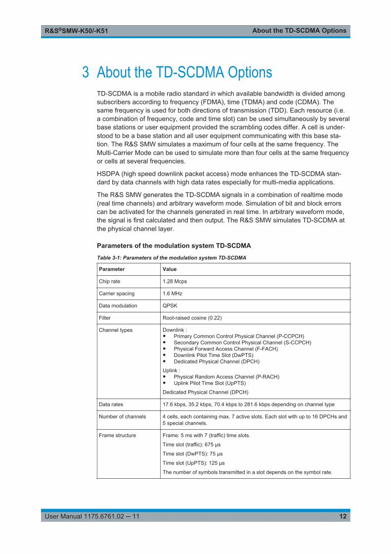
Parameters of the modulation system TD-SCDMA
Table 3-1: Parameters of the modulation system TD-SCDMA
Parameter Value
Chip rate 1.28 Mcps
Carrier spacing 1.6 MHz
Data modulation QPSK
Filter Root-raised cosine (0.22)
Channel types Downlink :● Primary Common Control Physical Channel (P-CCPCH)● Secondary Common Control Physical Channel (S-CCPCH)● Physical Forward Access Channel (F-FACH)● Downlink Pilot Time Slot (DwPTS)● Dedicated Physical Channel (DPCH)
Uplink :● Physical Random Access Channel (P-RACH)● Uplink Pilot Time Slot (UpPTS)
Dedicated Physical Channel (DPCH)
Data rates 17.6 kbps, 35.2 kbps, 70.4 kbps to 281.6 kbps depending on channel type
Number of channels 4 cells, each containing max. 7 active slots. Each slot with up to 16 DPCHs and5 special channels.
Frame structure Frame: 5 ms with 7 (traffic) time slots.
Time slot (traffic): 675 µs
Time slot (DwPTS): 75 µs
Time slot (UpPTS): 125 µs
The number of symbols transmitted in a slot depends on the symbol rate.
About the TD-SCDMA OptionsR&S®SMW-K50/-K51
13User Manual 1175.6761.02 ─ 11
Parameter Value
Scrambling code 128 different codes with length of 16 chips
SYNC codes 32 different codes with length of 64 chips
SYNC1 codes 256 different codes with length of 128 chips
Basic midamble codes 128 different codes with length of 128 chips
Spreading code "Orthogonal Variable Spreading Factor Code (OVSF)"; spreading factors 1, 2,4, 8, 16
3.1 Modulation System
3.1.1 TD-SCDMA Signal Structure (Frames and Time Slots)
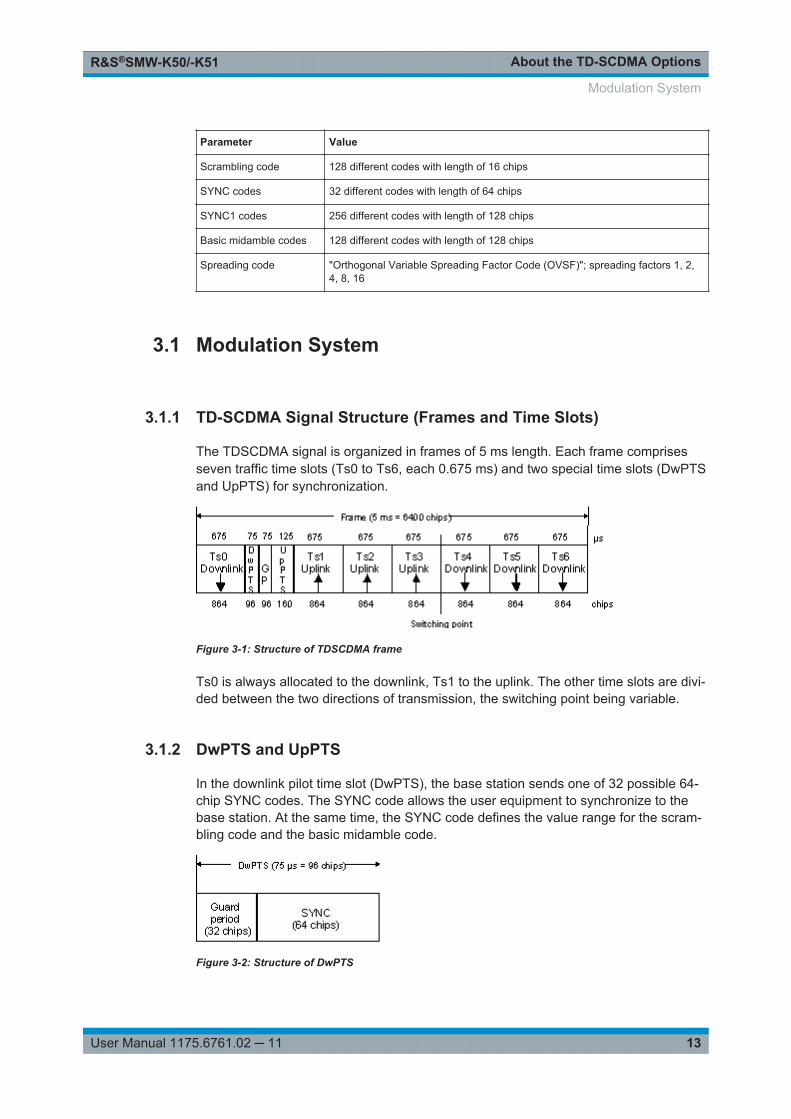
The TDSCDMA signal is organized in frames of 5 ms length. Each frame comprisesseven traffic time slots (Ts0 to Ts6, each 0.675 ms) and two special time slots (DwPTSand UpPTS) for synchronization.
Figure 3-1: Structure of TDSCDMA frame
Ts0 is always allocated to the downlink, Ts1 to the uplink. The other time slots are divi-ded between the two directions of transmission, the switching point being variable.
3.1.2 DwPTS and UpPTS
In the downlink pilot time slot (DwPTS), the base station sends one of 32 possible 64-chip SYNC codes. The SYNC code allows the user equipment to synchronize to thebase station. At the same time, the SYNC code defines the value range for the scram-bling code and the basic midamble code.
Figure 3-2: Structure of DwPTS
Modulation System
About the TD-SCDMA OptionsR&S®SMW-K50/-K51
14User Manual 1175.6761.02 ─ 11
The real-valued SYNC sequence is converted into a complex-valued SYNC sequenceby a rotating-vector operation.
This SYNC sequence is divided up into four symbols with 16 chips each. The symbolsare phase-modulated (possible phases are 45°, 135°, 225° and 315°) in order to signalthe frame number of the interleaver.
In the supplied software, all symbols are modulated with 45°.
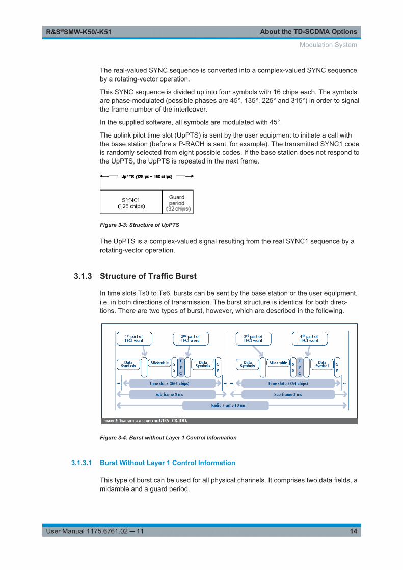
The uplink pilot time slot (UpPTS) is sent by the user equipment to initiate a call withthe base station (before a P-RACH is sent, for example). The transmitted SYNC1 codeis randomly selected from eight possible codes. If the base station does not respond tothe UpPTS, the UpPTS is repeated in the next frame.
Figure 3-3: Structure of UpPTS
The UpPTS is a complex-valued signal resulting from the real SYNC1 sequence by arotating-vector operation.
3.1.3 Structure of Traffic Burst
In time slots Ts0 to Ts6, bursts can be sent by the base station or the user equipment,i.e. in both directions of transmission. The burst structure is identical for both direc-tions. There are two types of burst, however, which are described in the following.
Figure 3-4: Burst without Layer 1 Control Information
3.1.3.1 Burst Without Layer 1 Control Information
This type of burst can be used for all physical channels. It comprises two data fields, amidamble and a guard period.
Modulation System
About the TD-SCDMA OptionsR&S®SMW-K50/-K51
15User Manual 1175.6761.02 ─ 11
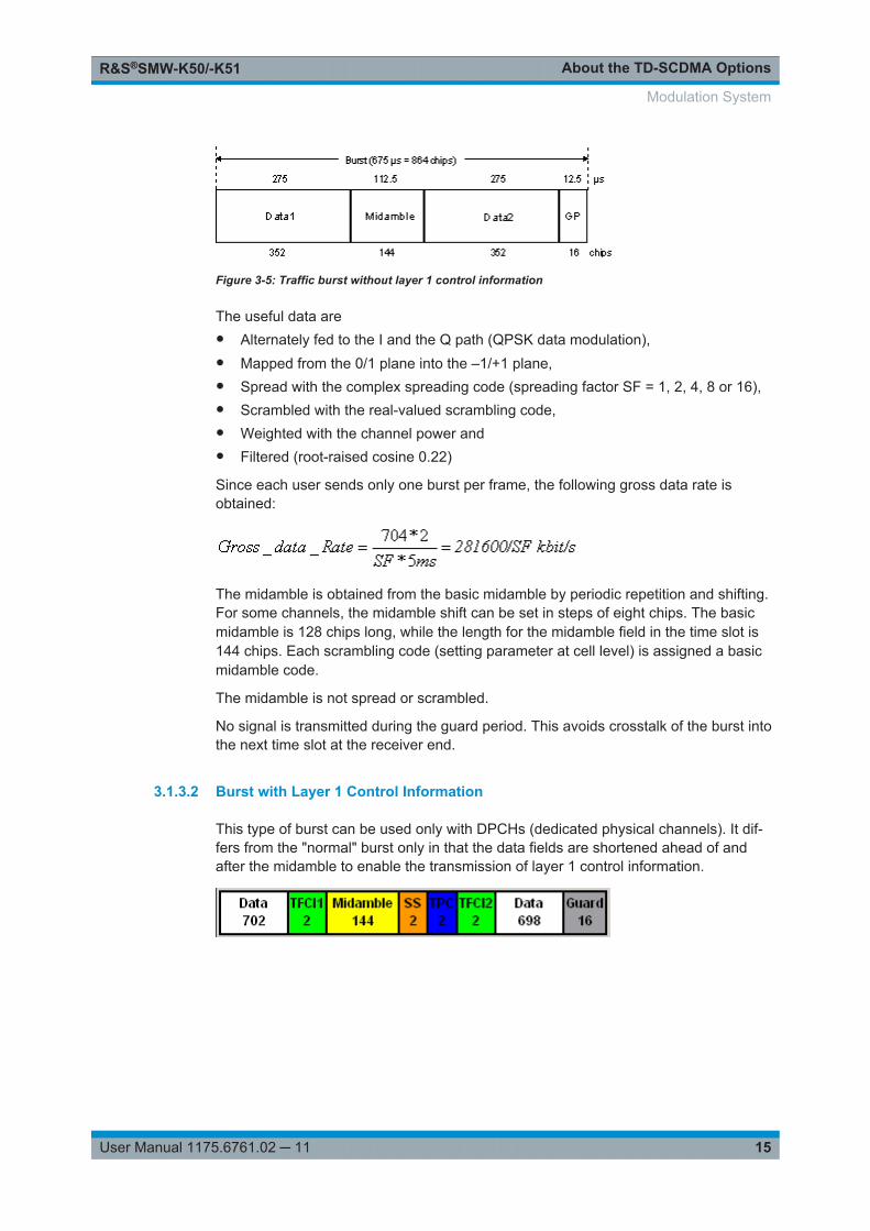
Figure 3-5: Traffic burst without layer 1 control information
The useful data are● Alternately fed to the I and the Q path (QPSK data modulation),● Mapped from the 0/1 plane into the –1/+1 plane,● Spread with the complex spreading code (spreading factor SF = 1, 2, 4, 8 or 16),● Scrambled with the real-valued scrambling code,● Weighted with the channel power and● Filtered (root-raised cosine 0.22)
Since each user sends only one burst per frame, the following gross data rate isobtained:
The midamble is obtained from the basic midamble by periodic repetition and shifting.For some channels, the midamble shift can be set in steps of eight chips. The basicmidamble is 128 chips long, while the length for the midamble field in the time slot is144 chips. Each scrambling code (setting parameter at cell level) is assigned a basicmidamble code.
The midamble is not spread or scrambled.
No signal is transmitted during the guard period. This avoids crosstalk of the burst intothe next time slot at the receiver end.
3.1.3.2 Burst with Layer 1 Control Information
This type of burst can be used only with DPCHs (dedicated physical channels). It dif-fers from the "normal" burst only in that the data fields are shortened ahead of andafter the midamble to enable the transmission of layer 1 control information.
Modulation System
About the TD-SCDMA OptionsR&S®SMW-K50/-K51
16User Manual 1175.6761.02 ─ 11
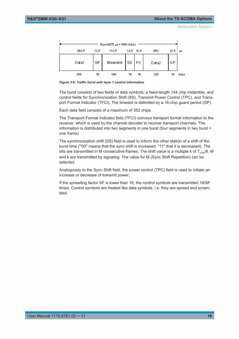
Figure 3-6: Traffic burst with layer 1 control information
The burst consists of two fields of data symbols, a fixed-length 144 chip midamble, andcontrol fields for Synchronization Shift (SS), Transmit Power Control (TPC), and Trans-port Format Indicator (TFCI). The timeslot is delimited by a 16-chip guard period (GP).
Each data field consists of a maximum of 352 chips.
The Transport Format Indicator field (TFCI) conveys transport format information to thereceiver, which is used by the channel decoder to recover transport channels. Theinformation is distributed into two segments in one burst (four segments in two burst =one frame)
The synchronization shift (SS) field is used to inform the other station of a shift of theburst time ('"00" means that the sync shift is increased, "11" that it is decreased). Thebits are transmitted in M consecutive frames. The shift value is a multiple k of Tchip/8. Mand k are transmitted by signaling. The value for M (Sync Shift Repetition) can beselected.
Analogously to the Sync Shift field, the power control (TPC) field is used to initiate anincrease or decrease of transmit power.
If the spreading factor SF is lower than 16, the control symbols are transmitted 16/SFtimes. Control symbols are treated like data symbols, i.e. they are spread and scram-bled.
Modulation System
TD-SCDMA Configuration and SettingsR&S®SMW-K50/-K51
17User Manual 1175.6761.02 ─ 11
4 TD-SCDMA Configuration and Settings► To access the TD-SCDMA settings, select "Baseband > TD-SCDMA".
Tip: The dialog is comprehensive. To simplify the description and the orientationthrough this documentation, the headings of the following section follow a commonnaming convention:<DialogName/TabName>< - ><SourceDialog>This common structure is intended to identify your current location in the dialog.
The remote commands required to define these settings are described in Chapter 5,"Remote-Control Commands", on page 89.
● General Settings..................................................................................................... 18● Trigger Settings.......................................................................................................20● Marker Settings.......................................................................................................24● Clock Settings......................................................................................................... 26● Local and Global Connector Settings......................................................................28● Common Cell Configuration Settings......................................................................28● Predefined Settings.................................................................................................31● Cell Configuration....................................................................................................32● Enhanced Channels Settings..................................................................................36● HSDPA/HSUPA Settings........................................................................................ 51● Slot Configuration....................................................................................................63● DPCCH Settings..................................................................................................... 71● Slot Mode PRACH Settings.................................................................................... 78● Filter / Clipping / ARB Settings................................................................................83● Power Ramping.......................................................................................................86
TD-SCDMA Configuration and SettingsR&S®SMW-K50/-K51
18User Manual 1175.6761.02 ─ 11
4.1 General Settings
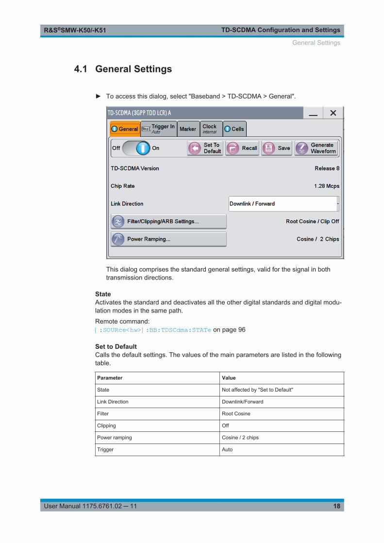
► To access this dialog, select "Baseband > TD-SCDMA > General".
This dialog comprises the standard general settings, valid for the signal in bothtransmission directions.
StateActivates the standard and deactivates all the other digital standards and digital modu-lation modes in the same path.
Remote command: [:SOURce<hw>]:BB:TDSCdma:STATe on page 96
Set to DefaultCalls the default settings. The values of the main parameters are listed in the followingtable.
Parameter Value
State Not affected by "Set to Default"
Link Direction Downlink/Forward
Filter Root Cosine
Clipping Off
Power ramping Cosine / 2 chips
Trigger Auto
General Settings
TD-SCDMA Configuration and SettingsR&S®SMW-K50/-K51
19User Manual 1175.6761.02 ─ 11
Remote command: [:SOURce<hw>]:BB:TDSCdma:PRESet on page 94
Save/RecallAccesses the "Save/Recall" dialog, that is the standard instrument function for storingand recalling the complete dialog-related settings in a file. The provided navigationpossibilities in the dialog are self-explanatory.
The filename and the directory, in which the settings are stored, are user-definable; thefile extension is however predefined.
See also, chapter "File and Data Management" in the R&S SMW user manual.
Remote command: [:SOURce<hw>]:BB:TDSCdma:SETTing:CATalog? on page 94[:SOURce<hw>]:BB:TDSCdma:SETTing:LOAD on page 95[:SOURce<hw>]:BB:TDSCdma:SETTing:STORe on page 95
Generate Waveform FileWith enabled signal generation, triggers the instrument to store the current settings asan ARB signal in a waveform file. Waveform files can be further processed by the ARBand/or as a multi-carrier or a multi-segment signal.
The filename and the directory it is stored in are user-definable; the predefined fileextension for waveform files is *.wv.
Remote command: [:SOURce<hw>]:BB:TDSCdma:WAVeform:CREate on page 96
TD-SCDMA VersionDisplays the current version of the TD-SCDMA standard.
The default settings and parameters provided are oriented towards the specificationsof the version displayed.
Remote command: [:SOURce<hw>]:BB:TDSCdma:VERSion? on page 96
Chip RateDisplays the system chip rate. This is fixed at 1.28 Mcps.
The output chip rate can be varied in the Filter/Clipping/ARB Settings dialog (seeChapter 4.14.1, "Filter Settings", on page 84).
Remote command: [:SOURce<hw>]:BB:TDSCdma:CRATe? on page 91
Link DirectionSelects the transmission direction.
The settings of the basestation or the user equipment are provided in the following dia-log section in accordance with the selection.
"Downlink/Forward"
The transmission direction selected is basestation to user equipment.The signal corresponds to that of a base station.
"Uplink/Reverse"
The transmission direction selected is user equipment to base sta-tion. The signal corresponds to that of a user equipment.
General Settings
TD-SCDMA Configuration and SettingsR&S®SMW-K50/-K51
20User Manual 1175.6761.02 ─ 11
Remote command: [:SOURce<hw>]:BB:TDSCdma:LINK on page 92
Filter / Clipping / ARB SettingsAccess to the dialog for setting baseband filtering, clipping and the sequence length ofthe arbitrary waveform component, see Chapter 4.14, "Filter / Clipping / ARB Settings",on page 83 .
Power Ramping…Accesses the dialog for setting the power ramping, see Chapter 4.15, "Power Ramp-ing", on page 86.
Remote command: n.a.
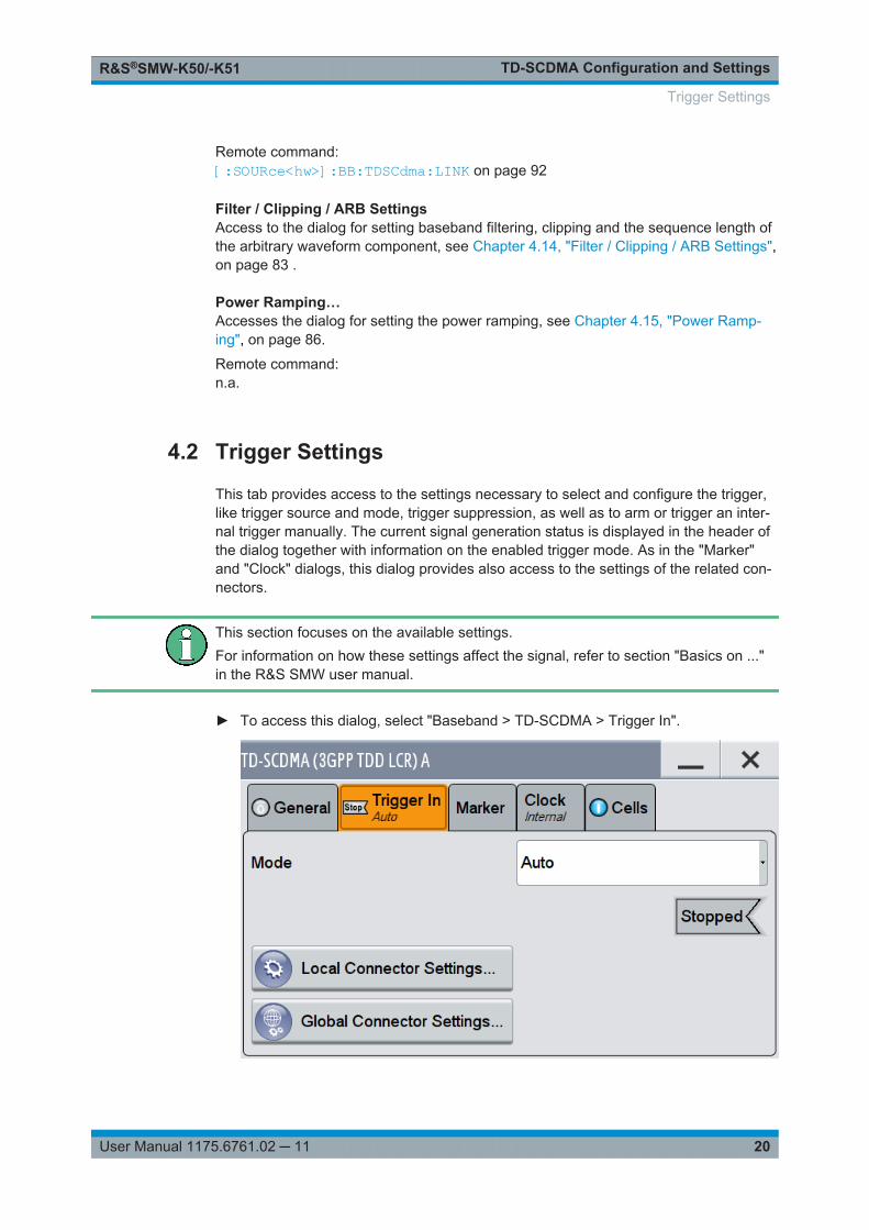
4.2 Trigger Settings
This tab provides access to the settings necessary to select and configure the trigger,like trigger source and mode, trigger suppression, as well as to arm or trigger an inter-nal trigger manually. The current signal generation status is displayed in the header ofthe dialog together with information on the enabled trigger mode. As in the "Marker"and "Clock" dialogs, this dialog provides also access to the settings of the related con-nectors.
This section focuses on the available settings.For information on how these settings affect the signal, refer to section "Basics on ..."in the R&S SMW user manual.
► To access this dialog, select "Baseband > TD-SCDMA > Trigger In".
Trigger Settings
TD-SCDMA Configuration and SettingsR&S®SMW-K50/-K51
21User Manual 1175.6761.02 ─ 11
This dialog comprises the settings required for configuring the trigger signal.
Routing and enabling a triggerThe provided trigger signals are not dedicated to a particular connector. Trigger signalscan be mapped to one or more globally shared USER or local T/M connectors.Use the Local and Global Connector Settings to configure the signal mapping, thepolarity, the trigger threshold and the input impedance of the input connectors.To route and enable a trigger signal, perform the following general steps:● Define the signal source and the effect of a trigger event.
Select the "Trigger In > Mode" and "Trigger In > Source".● Define the connector (USER or T/M) where the selected signal is provided.
Use the Local and Global Connector Settings.
Trigger Settings Common to All BasebandsTo enable simultaneous signal generation in all basebands, the R&S SMW couples thetrigger settings in the available basebands in any instrument's configuration involvingsignal routing with signal addition. For example, in MIMO configuration, routing andsumming of basebands or of streams.
The icon indicates that common trigger settings are applied.
You can access and configure the common trigger source and trigger mode settings inany of the basebands. An arm or a restart trigger event applies to all basebands, too.You can still apply different delay to each of the triggers individually.
Trigger Mode ← Trigger Settings Common to All BasebandsSelects trigger mode, i.e. determines the effect of a trigger event on the signal genera-tion.
For more information, refer to chapter "Basics" in the R&S SMW user manual.
● "Auto"The signal is generated continuously.
● "Retrigger"The signal is generated continuously. A trigger event (internal or external) causes arestart.
● "Armed Auto"The signal is generated only when a trigger event occurs. Then the signal is gener-ated continuously.An "Arm" stops the signal generation. A subsequent trigger event (internal with orexternal) causes a restart.
● "Armed Retrigger"The signal is generated only when a trigger event occurs. Then the signal is gener-ated continuously. Every subsequent trigger event causes a restart.An "Arm" stops signal generation. A subsequent trigger event (internal with orexternal) causes a restart.
● "Single"The signal is generated only when a trigger event occurs. Then the signal is gener-ated once to the length specified at "Signal Duration".Every subsequent trigger event (internal or external) causes a restart.
Trigger Settings
TD-SCDMA Configuration and SettingsR&S®SMW-K50/-K51
22User Manual 1175.6761.02 ─ 11
Remote command: [:SOURce<hw>]:BB:TDSCdma[:TRIGger]:SEQuence on page 104
Signal Duration Unit ← Trigger Settings Common to All BasebandsDefines the unit for describing the length of the signal sequence to be output in the"Single" trigger mode.
Remote command: [:SOURce<hw>]:BB:TDSCdma:TRIGger:SLUNit on page 103
Trigger Signal Duration ← Trigger Settings Common to All BasebandsEnters the length of the signal sequence to be output in the "Single" trigger mode.
Use this parameter to output part of the signal deliberately, an exact sequence of thesignal, or a defined number of repetitions of the signal.
Remote command: [:SOURce<hw>]:BB:TDSCdma:TRIGger:SLENgth on page 103
Running/Stopped ← Trigger Settings Common to All BasebandsWith enabled modulation, displays the status of signal generation for all trigger modes.● "Running"
The signal is generated; a trigger was (internally or externally) initiated in triggeredmode.
● "Stopped"The signal is not generated and the instrument waits for a trigger event.
Remote command: [:SOURce<hw>]:BB:TDSCdma:TRIGger:RMODe? on page 102
Arm ← Trigger Settings Common to All BasebandsStops the signal generation until a subsequent trigger event occurs.
Remote command: [:SOURce<hw>]:BB:TDSCdma:TRIGger:ARM:EXECute on page 101
Execute Trigger ← Trigger Settings Common to All BasebandsFor internal trigger source, executes trigger manually.
Remote command: [:SOURce<hw>]:BB:TDSCdma:TRIGger:EXECute on page 101
Trigger Source ← Trigger Settings Common to All BasebandsThe following sources of the trigger signal are available:● "Internal"
The trigger event is executed manually by the "Execute Trigger".● "Internal (Baseband A/B)"
The trigger event is provided by the trigger signal from the other basebands.If common trigger settings are applied, this trigger source is disabled.
● "External Global Trigger 1 / 2"The trigger event is the active edge of an external trigger signal provided and con-figured at the global USER connectors.
● "External Local Trigger"
Trigger Settings
TD-SCDMA Configuration and SettingsR&S®SMW-K50/-K51
23User Manual 1175.6761.02 ─ 11
The trigger event is the active edge of an external trigger signal provided and con-figured at the local T/M/C connector.With coupled trigger settings, the signal has to be provided at the T/M/C1/2/3 con-nectors.
● "External Local Clock"The trigger event is the active edge of an external local clock signal provided andconfigured at the local T/M/C connector.With coupled trigger settings, the signal has to be provided at the T/M/C1 connec-tor.
● "Baseband Sync In"Option: R&S SMW-B9In master-slave mode, slave instruments are triggered by the active edge of thesynchronization signal.
"External Local Clock/Trigger" require R&S SMW-B10.
Remote command: [:SOURce<hw>]:BB:TDSCdma:TRIGger:SOURce on page 103
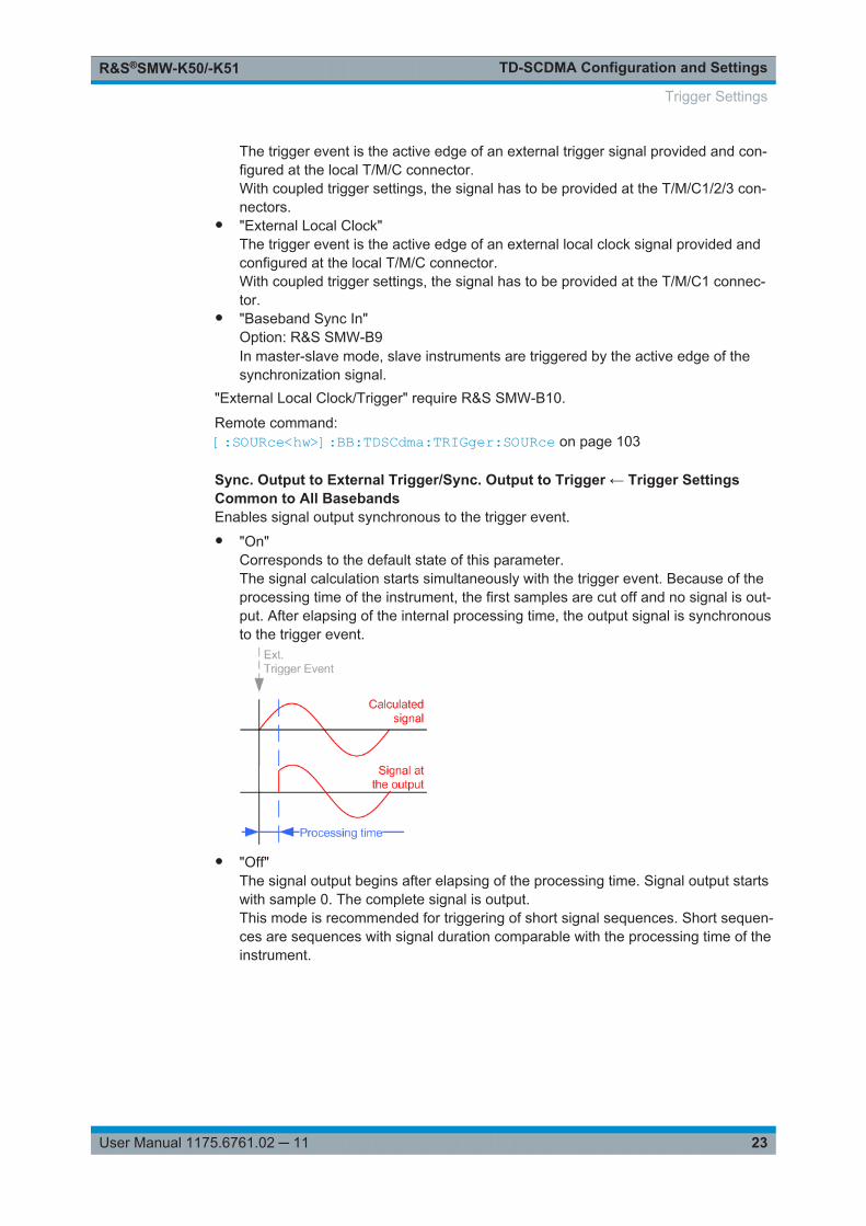
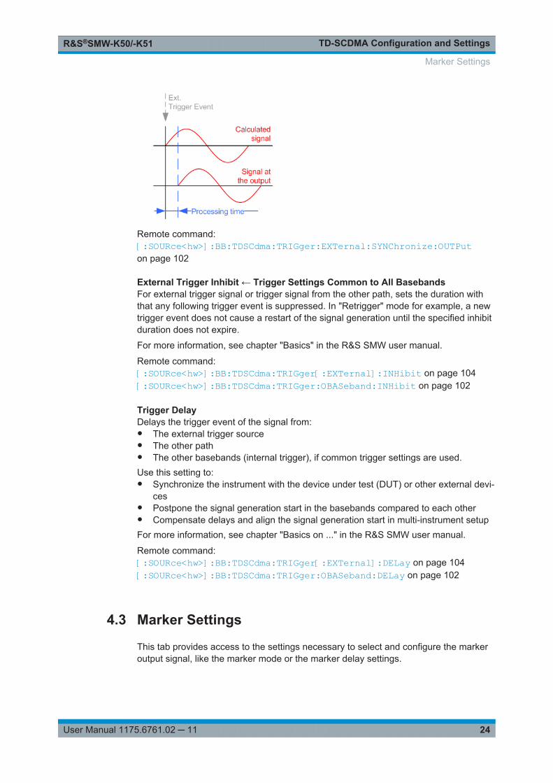
Sync. Output to External Trigger/Sync. Output to Trigger ← Trigger SettingsCommon to All BasebandsEnables signal output synchronous to the trigger event.● "On"
Corresponds to the default state of this parameter.The signal calculation starts simultaneously with the trigger event. Because of theprocessing time of the instrument, the first samples are cut off and no signal is out-put. After elapsing of the internal processing time, the output signal is synchronousto the trigger event.
● "Off"The signal output begins after elapsing of the processing time. Signal output startswith sample 0. The complete signal is output.This mode is recommended for triggering of short signal sequences. Short sequen-ces are sequences with signal duration comparable with the processing time of theinstrument.
Trigger Settings
TD-SCDMA Configuration and SettingsR&S®SMW-K50/-K51
24User Manual 1175.6761.02 ─ 11
Remote command: [:SOURce<hw>]:BB:TDSCdma:TRIGger:EXTernal:SYNChronize:OUTPuton page 102
External Trigger Inhibit ← Trigger Settings Common to All BasebandsFor external trigger signal or trigger signal from the other path, sets the duration withthat any following trigger event is suppressed. In "Retrigger" mode for example, a newtrigger event does not cause a restart of the signal generation until the specified inhibitduration does not expire.
For more information, see chapter "Basics" in the R&S SMW user manual.
Remote command: [:SOURce<hw>]:BB:TDSCdma:TRIGger[:EXTernal]:INHibit on page 104[:SOURce<hw>]:BB:TDSCdma:TRIGger:OBASeband:INHibit on page 102
Trigger DelayDelays the trigger event of the signal from:● The external trigger source● The other path● The other basebands (internal trigger), if common trigger settings are used.Use this setting to:● Synchronize the instrument with the device under test (DUT) or other external devi-
ces● Postpone the signal generation start in the basebands compared to each other● Compensate delays and align the signal generation start in multi-instrument setupFor more information, see chapter "Basics on ..." in the R&S SMW user manual.
Remote command: [:SOURce<hw>]:BB:TDSCdma:TRIGger[:EXTernal]:DELay on page 104[:SOURce<hw>]:BB:TDSCdma:TRIGger:OBASeband:DELay on page 102
4.3 Marker Settings
This tab provides access to the settings necessary to select and configure the markeroutput signal, like the marker mode or the marker delay settings.
Marker Settings
TD-SCDMA Configuration and SettingsR&S®SMW-K50/-K51
25User Manual 1175.6761.02 ─ 11
This section focuses on the available settings.For information on how these settings affect the signal, refer to section "Basics on ..."in the R&S SMW user manual.
Access:
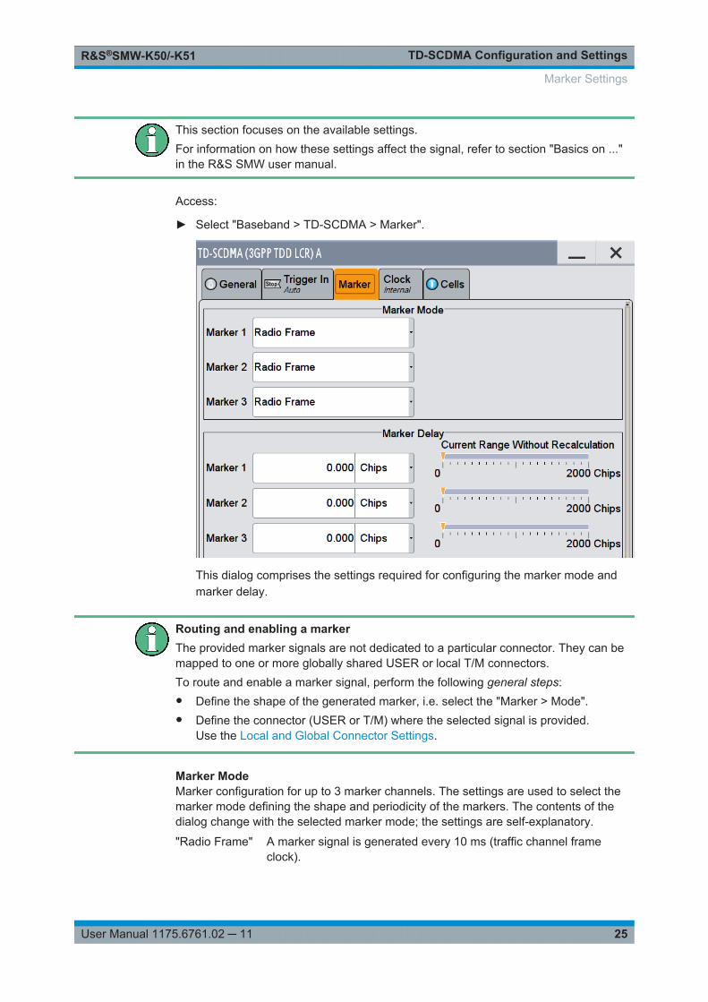
► Select "Baseband > TD-SCDMA > Marker".
This dialog comprises the settings required for configuring the marker mode andmarker delay.
Routing and enabling a markerThe provided marker signals are not dedicated to a particular connector. They can bemapped to one or more globally shared USER or local T/M connectors.To route and enable a marker signal, perform the following general steps:● Define the shape of the generated marker, i.e. select the "Marker > Mode".● Define the connector (USER or T/M) where the selected signal is provided.
Use the Local and Global Connector Settings.
Marker ModeMarker configuration for up to 3 marker channels. The settings are used to select themarker mode defining the shape and periodicity of the markers. The contents of thedialog change with the selected marker mode; the settings are self-explanatory.
"Radio Frame" A marker signal is generated every 10 ms (traffic channel frameclock).
Marker Settings
TD-SCDMA Configuration and SettingsR&S®SMW-K50/-K51
26User Manual 1175.6761.02 ─ 11
"Chip Sequence Period (ARB)"A marker signal is generated at the beginning of every arbitrary wave-form sequence (depending on the set sequence length). The markersignal is generated regardless of whether an ARB component isused.
"System Frame Number (SFN) Restart"A marker signal is generated at the start of every SFN period (every4096 frames).
"On/Off Ratio" A regular marker signal that is defined by an on/off ratio is generated.A period lasts one on and off cycle.
Remote command: [:SOURce<hw>]:BB:TDSCdma:TRIGger:OUTPut<ch>:ONTime on page 106[:SOURce<hw>]:BB:TDSCdma:TRIGger:OUTPut<ch>:OFFTime on page 106
"User Period" A marker signal is generated at the beginning of every user-definedperiod. The period is defined in "Period."
Remote command: [:SOURce<hw>]:BB:TDSCdma:TRIGger:OUTPut<ch>:PERiod on page 106
Remote command: [:SOURce<hw>]:BB:TDSCdma:TRIGger:OUTPut<ch>:ONTime on page 106[:SOURce<hw>]:BB:TDSCdma:TRIGger:OUTPut<ch>:OFFTime on page 106[:SOURce<hw>]:BB:TDSCdma:TRIGger:OUTPut<ch>:PERiod on page 106[:SOURce<hw>]:BB:TDSCdma:TRIGger:OUTPut<ch>:MODE on page 105
Marker x DelayDelays the marker signal at the marker output relative to the signal generation start.
Variation of the parameter "Marker x Delay" causes signal recalculation, regardless ofthe indication "Current Range without Recalculation".
Remote command: [:SOURce<hw>]:BB:TDSCdma:TRIGger:OUTPut<ch>:DELay on page 106
4.4 Clock Settings
This dialog provides access to the settings necessary to select and configure the clocksignal, like the clock source and clock mode.
This section focuses on the available settings.For information on how these settings affect the signal, refer to section "Basics on ..."in the R&S SMW user manual.
► To access this dialog, select "Baseband > TD-SCDMA >Clock".
Clock Settings
TD-SCDMA Configuration and SettingsR&S®SMW-K50/-K51
27User Manual 1175.6761.02 ─ 11
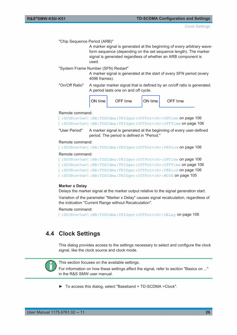
This dialog comprises the settings required for configuring the clock.
Defining the ClockThe provided clock signals are not dedicated to a particular connector. They can bemapped to one or more globally shared USER and the local T/M/C connectors.Use the Local and Global Connector Settings to configure the signal mapping, thepolarity, the trigger threshold, and the input impedance of the input connectors.To route and enable a trigger signal, perform the following general steps:● Define the signal source, that is select the "Clock > Source".● Define the connector (USER or T/M) where the selected signal is provided.
Use the Local and Global Connector Settings.
Clock SourceSelects the clock source.● "Internal"
The instrument uses its internal clock reference.● "External Local Clock"
The instrument expects an external clock reference at the local T/M/C connector."External Local Clock" requires R&S SMW-B10.
Remote command: [:SOURce<hw>]:BB:TDSCdma:CLOCk:SOURce on page 107
Clock Mode(requires R&S SMW-B10)
Sets the type of externally supplied clock.
Remote command: [:SOURce<hw>]:BB:TDSCdma:CLOCk:MODE on page 107
Measured External ClockProvided for permanent monitoring of the enabled and externally supplied clock signal.
Remote command: CLOCk:INPut:FREQuency?
Clock Settings
TD-SCDMA Configuration and SettingsR&S®SMW-K50/-K51
28User Manual 1175.6761.02 ─ 11
4.5 Local and Global Connector Settings
Each of the "Trigger In", "Marker" and "Clock" dialogs as well as the "Trigger MarkerClock" dialog provides a quick access to the related local and global connector set-tings.
For more information, refer to the description R&S SMW User Manual, section "Localand Global Connectors".
4.6 Common Cell Configuration Settings
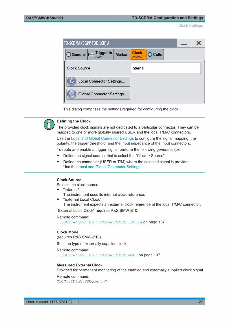
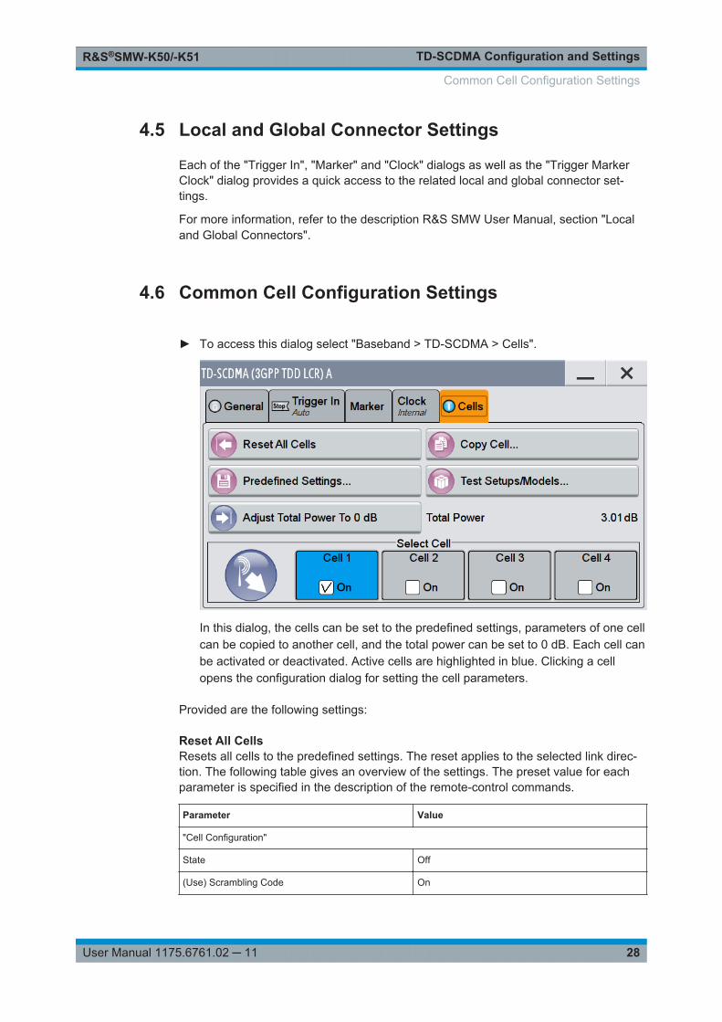
► To access this dialog select "Baseband > TD-SCDMA > Cells".
In this dialog, the cells can be set to the predefined settings, parameters of one cellcan be copied to another cell, and the total power can be set to 0 dB. Each cell canbe activated or deactivated. Active cells are highlighted in blue. Clicking a cellopens the configuration dialog for setting the cell parameters.
Provided are the following settings:
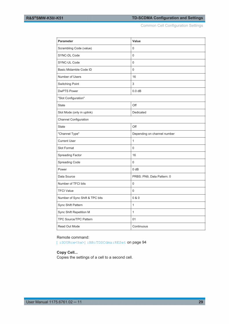
Reset All CellsResets all cells to the predefined settings. The reset applies to the selected link direc-tion. The following table gives an overview of the settings. The preset value for eachparameter is specified in the description of the remote-control commands.
Parameter Value
"Cell Configuration"
State Off
(Use) Scrambling Code On
Common Cell Configuration Settings
TD-SCDMA Configuration and SettingsR&S®SMW-K50/-K51
29User Manual 1175.6761.02 ─ 11
Parameter Value
Scrambling Code (value) 0
SYNC-DL Code 0
SYNC-UL Code 0
Basic Midamble Code ID 0
Number of Users 16
Switching Point 3
DwPTS Power 0.0 dB
"Slot Configuration"
State Off
Slot Mode (only in uplink) Dedicated
Channel Configuration
State Off
"Channel Type" Depending on channel number
Current User 1
Slot Format 0
Spreading Factor 16
Spreading Code 0
Power 0 dB
Data Source PRBS: PN9, Data Pattern: 0
Number of TFCI bits 0
TFCI Value 0
Number of Sync Shift & TPC bits 0 & 0
Sync Shift Pattern 1
Sync Shift Repetition M 1
TPC Source/TPC Pattern 01
Read Out Mode Continuous
Remote command: [:SOURce<hw>]:BB:TDSCdma:RESet on page 94
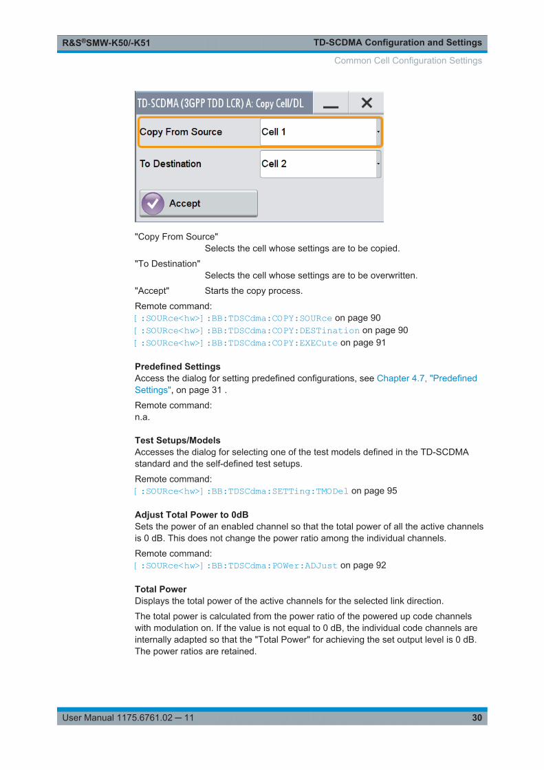
Copy Cell...Copies the settings of a cell to a second cell.
Common Cell Configuration Settings
TD-SCDMA Configuration and SettingsR&S®SMW-K50/-K51
30User Manual 1175.6761.02 ─ 11
"Copy From Source"Selects the cell whose settings are to be copied.
"To Destination"Selects the cell whose settings are to be overwritten.
"Accept" Starts the copy process.
Remote command: [:SOURce<hw>]:BB:TDSCdma:COPY:SOURce on page 90[:SOURce<hw>]:BB:TDSCdma:COPY:DESTination on page 90[:SOURce<hw>]:BB:TDSCdma:COPY:EXECute on page 91
Predefined SettingsAccess the dialog for setting predefined configurations, see Chapter 4.7, "PredefinedSettings", on page 31 .
Remote command: n.a.
Test Setups/ModelsAccesses the dialog for selecting one of the test models defined in the TD-SCDMAstandard and the self-defined test setups.
Remote command: [:SOURce<hw>]:BB:TDSCdma:SETTing:TMODel on page 95
Adjust Total Power to 0dBSets the power of an enabled channel so that the total power of all the active channelsis 0 dB. This does not change the power ratio among the individual channels.
Remote command: [:SOURce<hw>]:BB:TDSCdma:POWer:ADJust on page 92
Total PowerDisplays the total power of the active channels for the selected link direction.
The total power is calculated from the power ratio of the powered up code channelswith modulation on. If the value is not equal to 0 dB, the individual code channels areinternally adapted so that the "Total Power" for achieving the set output level is 0 dB.The power ratios are retained.
Common Cell Configuration Settings
TD-SCDMA Configuration and SettingsR&S®SMW-K50/-K51
31User Manual 1175.6761.02 ─ 11
Remote command: [:SOURce<hw>]:BB:TDSCdma:POWer[:TOTal]? on page 92
Select CellSelects the cell and accesses the corresponding dialog with cell-related settings, seeChapter 4.8, "Cell Configuration", on page 32.
Remote command: n.a.
Cell On / Cell OffActivates or deactivates the cells.
Remote command: [:SOURce<hw>]:BB:TDSCdma:DOWN|UP:CELL<st>:STATe on page 112
4.7 Predefined Settings
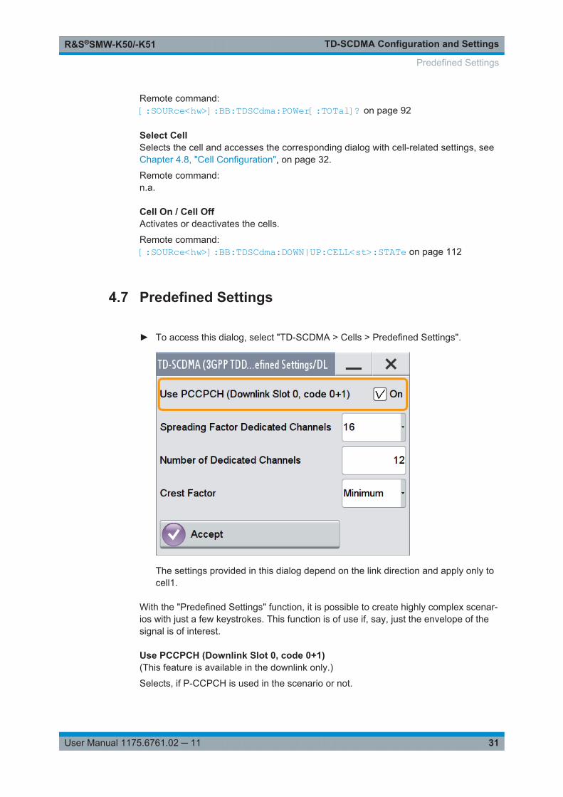
► To access this dialog, select "TD-SCDMA > Cells > Predefined Settings".
The settings provided in this dialog depend on the link direction and apply only tocell1.
With the "Predefined Settings" function, it is possible to create highly complex scenar-ios with just a few keystrokes. This function is of use if, say, just the envelope of thesignal is of interest.
Use PCCPCH (Downlink Slot 0, code 0+1)(This feature is available in the downlink only.)
Selects, if P-CCPCH is used in the scenario or not.
Predefined Settings
TD-SCDMA Configuration and SettingsR&S®SMW-K50/-K51
32User Manual 1175.6761.02 ─ 11
If P-CCPCH is used, both P-CCPCHs are activated in slot 0 with spreading code 0+1.
Remote command: [:SOURce<hw>]:BB:TDSCdma:DOWN:PPARameter:PCCPch:STATe on page 109
Spreading Factor Dedicated ChannelsSelects the spreading factor for the DPCHs.
The available spreading factors depend on the link direction.
Remote command: [:SOURce<hw>]:BB:TDSCdma:DOWN|UP:PPARameter:DPCH:SFACtoron page 108
Number of Dedicated ChannelsSets the number of activated DPCHs.
The minimum number is 1 and the maximum number depends on the spreading factor:
Max. No. DPCH = 3 x "Spreading Factor"
Remote command: [:SOURce<hw>]:BB:TDSCdma:DOWN|UP:PPARameter:DPCH:COUNt on page 107
Crest FactorSelects the desired range for the crest factor scenario.
The crest factor of the signal is kept in the desired range by varying the distribution ofthe channels inside one slot and in between several slots.
"Minimum" The crest factor is minimized. The channels are distributed uniformlyover the slots and over the code domain of the individual slot.
"Average" An average crest factor is set. The channels are distributed uniformlyover the slots and successively in the code domain of the individualslot.
"Worst" The crest factor is set to an unfavorable value (i.e. maximum). Thechannels are distributed in clusters over the slots and successively inthe code domain of the individual slot.
Remote command: [:SOURce<hw>]:BB:TDSCdma:DOWN|UP:PPARameter:DPCH:CRESt on page 108
AcceptPresets the channel table of cell 1 with the parameters defined in the "Predefined Set-tings" dialog.
Remote command: [:SOURce<hw>]:BB:TDSCdma:DOWN|UP:PPARameter:EXECute on page 109
4.8 Cell Configuration
The "Cell" dialog provides the parameters for configuring general cell settings, andspecific slot-related settings.
Cell Configuration
TD-SCDMA Configuration and SettingsR&S®SMW-K50/-K51
33User Manual 1175.6761.02 ─ 11
4.8.1 Common Settings
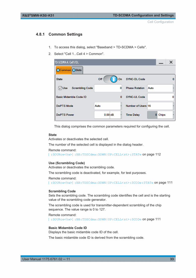
1. To access this dialog, select "Baseband > TD-SCDMA > Cells".
2. Select "Cell 1...Cell 4 > Common".
This dialog comprises the common parameters required for configuring the cell.
StateActivates or deactivates the selected cell.
The number of the selected cell is displayed in the dialog header.
Remote command: [:SOURce<hw>]:BB:TDSCdma:DOWN|UP:CELL<st>:STATe on page 112
Use (Scrambling Code)Activates or deactivates the scrambling code.
The scrambling code is deactivated, for example, for test purposes.
Remote command: [:SOURce<hw>]:BB:TDSCdma:DOWN|UP:CELL<st>:SCODe:STATe on page 111
Scrambling CodeSets the scrambling code. The scrambling code identifies the cell and is the startingvalue of the scrambling code generator.
The scrambling code is used for transmitter-dependent scrambling of the chipsequence. The value range is 0 to 127.
Remote command: [:SOURce<hw>]:BB:TDSCdma:DOWN|UP:CELL<st>:SCODe on page 111
Basic Midamble Code IDDisplays the basic midamble code ID of the cell.
The basic midamble code ID is derived from the scrambling code.
Cell Configuration
TD-SCDMA Configuration and SettingsR&S®SMW-K50/-K51
34User Manual 1175.6761.02 ─ 11
Remote command: [:SOURce<hw>]:BB:TDSCdma:DOWN|UP:CELL<st>:MCODe? on page 110
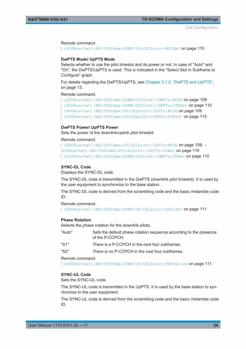
DwPTS Mode/ UpPTS ModeSelects whether to use the pilot timeslot and its power or not. In case of "Auto" and"On", the DwPTS/UpPTS is used. This is indicated in the "Select Slot in Subframe toConfigure" graph.
For details regarding the DwPTS/UpPTS, see Chapter 3.1.2, "DwPTS and UpPTS",on page 13.
Remote command: [:SOURce<hw>]:BB:TDSCdma:DOWN:CELL<st>:DWPTs:MODE on page 109[:SOURce<hw>]:BB:TDSCdma:DOWN:CELL<st>:DWPTs:STATe? on page 110[:SOURce<hw>]:BB:TDSCdma:UP:CELL<st>:UPPTs:MODE on page 109[:SOURce<hw>]:BB:TDSCdma:UP:CELL<st>:UPPTs:STATe? on page 110
DwPTS Power/ UpPTS PowerSets the power of the downlink/uplink pilot timeslot.
Remote command: [:SOURce<hw>]:BB:TDSCdma:UP:CELL<st>:UPPTs:MODE on page 109[:SOURce<hw>]:BB:TDSCdma:UP:CELL<st>:UPPTs:POWer on page 110[:SOURce<hw>]:BB:TDSCdma:DOWN:CELL<st>:DWPTs:POWer on page 110
SYNC-DL CodeDisplays the SYNC-DL code.
The SYNC-DL code is transmitted in the DwPTS (downlink pilot timeslot). It is used bythe user equipment to synchronize to the base station.
The SYNC-DL code is derived from the scrambling code and the basic midamble codeID.
Remote command: [:SOURce<hw>]:BB:TDSCdma:DOWN|UP:CELL<st>:SDCode? on page 111
Phase RotationSelects the phase rotation for the downlink pilots.
"Auto" Sets the default phase rotation sequence according to the presenceof the P-CCPCH.
"S1" There is a P-CCPCH in the next four subframes.
"S2" There is no P-CCPCH in the next four subframes.
Remote command: [:SOURce<hw>]:BB:TDSCdma:DOWN|UP:CELL<st>:PROTation on page 111
SYNC-UL CodeSets the SYNC-UL code.
The SYNC-UL code is transmitted in the UpPTS. It is used by the base station to syn-chronize to the user equipment.
The SYNC-UL code is derived from the scrambling code and the basic midamble codeID.
Cell Configuration
TD-SCDMA Configuration and SettingsR&S®SMW-K50/-K51
35User Manual 1175.6761.02 ─ 11
Remote command: [:SOURce<hw>]:BB:TDSCdma:DOWN|UP:CELL<st>:SUCode on page 112
Number of UsersSelects the total number of users of the cell. The number of users influences the actualmidamble sequence transmitted in the burst.
Remote command: [:SOURce<hw>]:BB:TDSCdma:DOWN|UP:CELL<st>:USERs on page 113
Time Delay(This feature is available for cell 2, 3, and 4 only)
Enters the time delay of the signal of the selected cell compared to the signal of cell 1.
Remote command: [:SOURce<hw>]:BB:TDSCdma:DOWN|UP:CELL<st>:TDELay on page 112
4.8.2 Slots
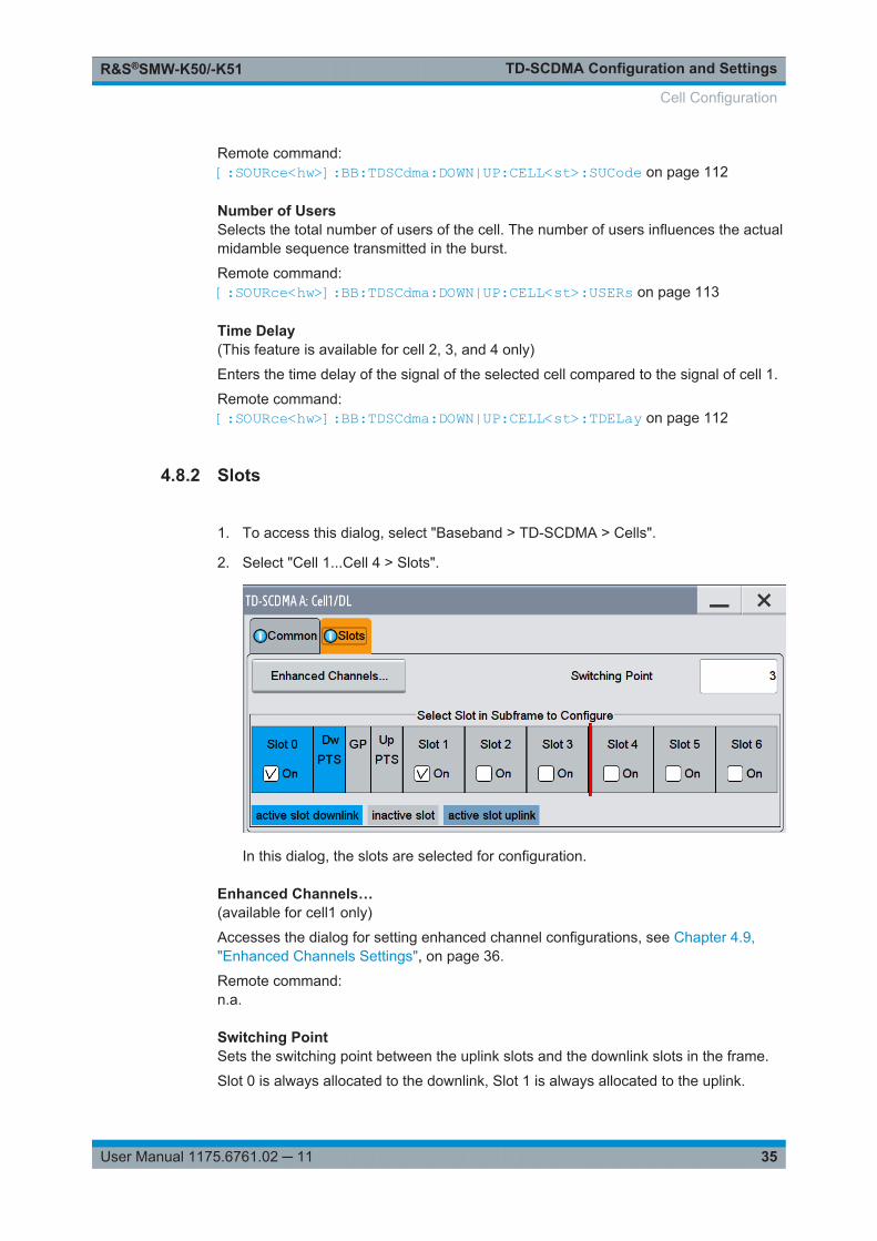
1. To access this dialog, select "Baseband > TD-SCDMA > Cells".
2. Select "Cell 1...Cell 4 > Slots".
In this dialog, the slots are selected for configuration.
Enhanced Channels…(available for cell1 only)
Accesses the dialog for setting enhanced channel configurations, see Chapter 4.9,"Enhanced Channels Settings", on page 36.
Remote command: n.a.
Switching PointSets the switching point between the uplink slots and the downlink slots in the frame.
Slot 0 is always allocated to the downlink, Slot 1 is always allocated to the uplink.
Cell Configuration
TD-SCDMA Configuration and SettingsR&S®SMW-K50/-K51
36User Manual 1175.6761.02 ─ 11
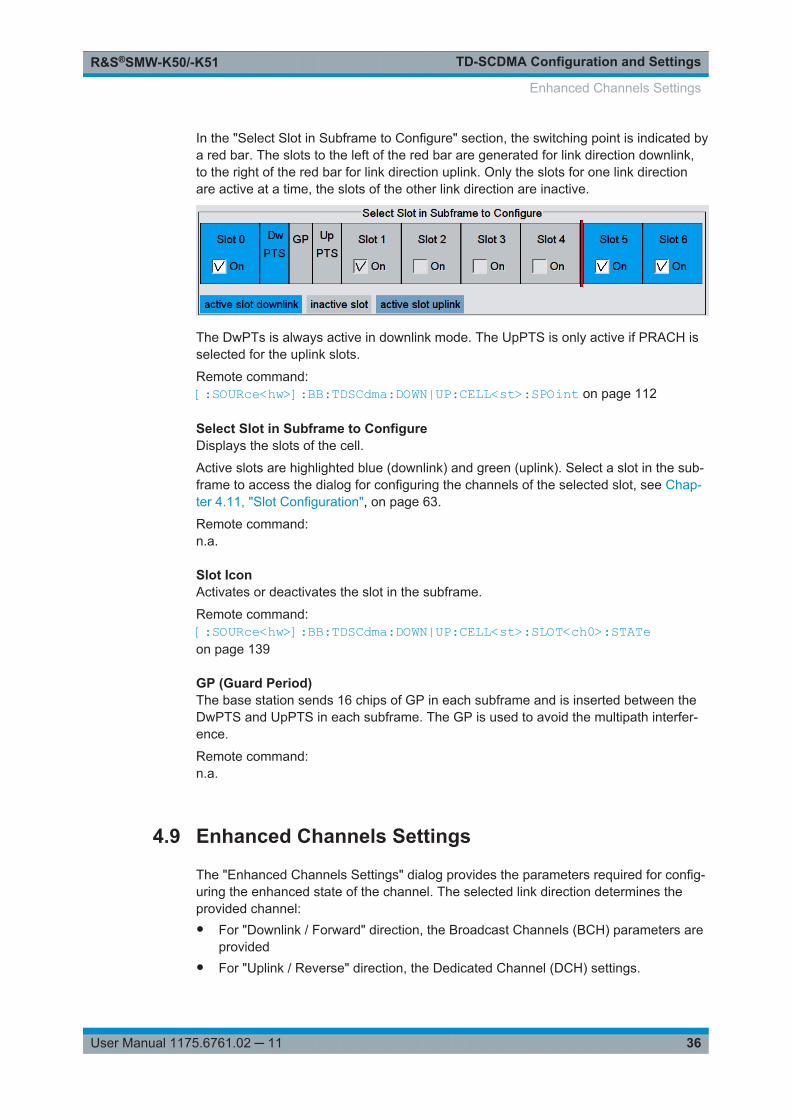
In the "Select Slot in Subframe to Configure" section, the switching point is indicated bya red bar. The slots to the left of the red bar are generated for link direction downlink,to the right of the red bar for link direction uplink. Only the slots for one link directionare active at a time, the slots of the other link direction are inactive.
The DwPTs is always active in downlink mode. The UpPTS is only active if PRACH isselected for the uplink slots.
Remote command: [:SOURce<hw>]:BB:TDSCdma:DOWN|UP:CELL<st>:SPOint on page 112
Select Slot in Subframe to ConfigureDisplays the slots of the cell.
Active slots are highlighted blue (downlink) and green (uplink). Select a slot in the sub-frame to access the dialog for configuring the channels of the selected slot, see Chap-ter 4.11, "Slot Configuration", on page 63.
Remote command: n.a.
Slot IconActivates or deactivates the slot in the subframe.
Remote command: [:SOURce<hw>]:BB:TDSCdma:DOWN|UP:CELL<st>:SLOT<ch0>:STATeon page 139
GP (Guard Period)The base station sends 16 chips of GP in each subframe and is inserted between theDwPTS and UpPTS in each subframe. The GP is used to avoid the multipath interfer-ence.
Remote command: n.a.
4.9 Enhanced Channels Settings
The "Enhanced Channels Settings" dialog provides the parameters required for config-uring the enhanced state of the channel. The selected link direction determines theprovided channel:● For "Downlink / Forward" direction, the Broadcast Channels (BCH) parameters are
provided● For "Uplink / Reverse" direction, the Dedicated Channel (DCH) settings.
Enhanced Channels Settings
TD-SCDMA Configuration and SettingsR&S®SMW-K50/-K51
37User Manual 1175.6761.02 ─ 11
All further parameters are available for both link directions.
● Broadcast Channels (BCH) Common Settings....................................................... 37● Broadcast Channels (BCH) Details Settings...........................................................38● Dedicated Channels (DCH) Common Settings.......................................................39● Dedicated Channels (DCH) Details Settings...........................................................42● Transport Channel.................................................................................................. 43● RMC PLCCH Channel Settings.............................................................................. 47● RMC HS-SICH Channel Settings............................................................................48● Bit and Block Error Insertion................................................................................... 50
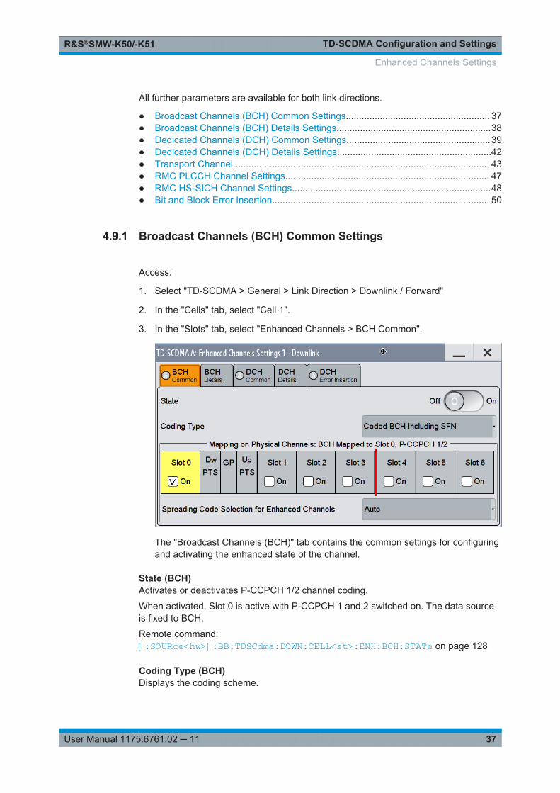
4.9.1 Broadcast Channels (BCH) Common Settings
Access:
1. Select "TD-SCDMA > General > Link Direction > Downlink / Forward"
2. In the "Cells" tab, select "Cell 1".
3. In the "Slots" tab, select "Enhanced Channels > BCH Common".
The "Broadcast Channels (BCH)" tab contains the common settings for configuringand activating the enhanced state of the channel.
State (BCH)Activates or deactivates P-CCPCH 1/2 channel coding.
When activated, Slot 0 is active with P-CCPCH 1 and 2 switched on. The data sourceis fixed to BCH.
Remote command: [:SOURce<hw>]:BB:TDSCdma:DOWN:CELL<st>:ENH:BCH:STATe on page 128
Coding Type (BCH)Displays the coding scheme.
Enhanced Channels Settings
TD-SCDMA Configuration and SettingsR&S®SMW-K50/-K51
38User Manual 1175.6761.02 ─ 11
The coding scheme of P-CCPCH (BCH) is specified in the standard. The channel isgenerated automatically with the counting system frame number (SFN). The systeminformation after the SFN field is provided by the selected data source.
Remote command: [:SOURce<hw>]:BB:TDSCdma:DOWN:CELL<st>:ENH:BCH:TYPE? on page 128
Mapping On Physical Channels: BCH mapped to <Slot> 0, P-CCPCH1/2Displays the slots of Cell 1 used to transmit the broadcast channels. For BCH, Slot 0 isalways used.
Remote command: [:SOURce<hw>]:BB:TDSCdma:DOWN:CELL<st>:ENH:BCH:SLOTstate<ch0>?on page 128
Spreading Code Selection (BCH)Selects if the spreading code of the channels is set automatically or manually. ForBCH, the spreading code is always set to "Auto" as the spreading code for the P-CCPCH is defined by the standard.
Remote command: [:SOURce<hw>]:BB:TDSCdma:DOWN:CELL<st>:ENH:BCH:SCSMode?on page 127
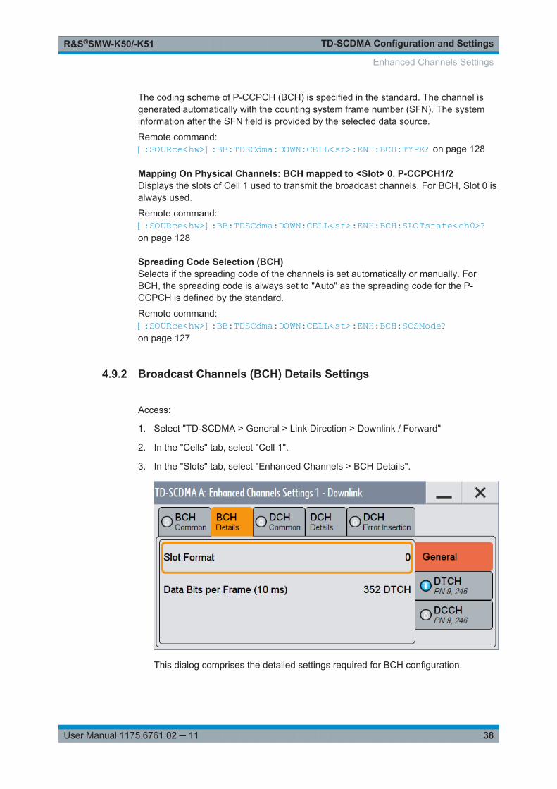
4.9.2 Broadcast Channels (BCH) Details Settings
Access:
1. Select "TD-SCDMA > General > Link Direction > Downlink / Forward"
2. In the "Cells" tab, select "Cell 1".
3. In the "Slots" tab, select "Enhanced Channels > BCH Details".
This dialog comprises the detailed settings required for BCH configuration.
Enhanced Channels Settings
TD-SCDMA Configuration and SettingsR&S®SMW-K50/-K51
39User Manual 1175.6761.02 ─ 11
Slot FormatDisplays the slot format of the selected channel.
A slot format defines the complete structure of a slot made of data and control fields.The slot format depends on the coding type selected.
Remote command: [:SOURce<hw>]:BB:TDSCdma:DOWN:CELL<st>:ENH:BCH:SFORmat?on page 127
Data Bits Per Frame (10 ms)Displays the data bits in the DPDCH component of the DPCH frame at physical level.The value depends on the slot format.
Remote command: [:SOURce<hw>]:BB:TDSCdma:DOWN:CELL<st>:ENH:BCH:BPFRame?on page 124
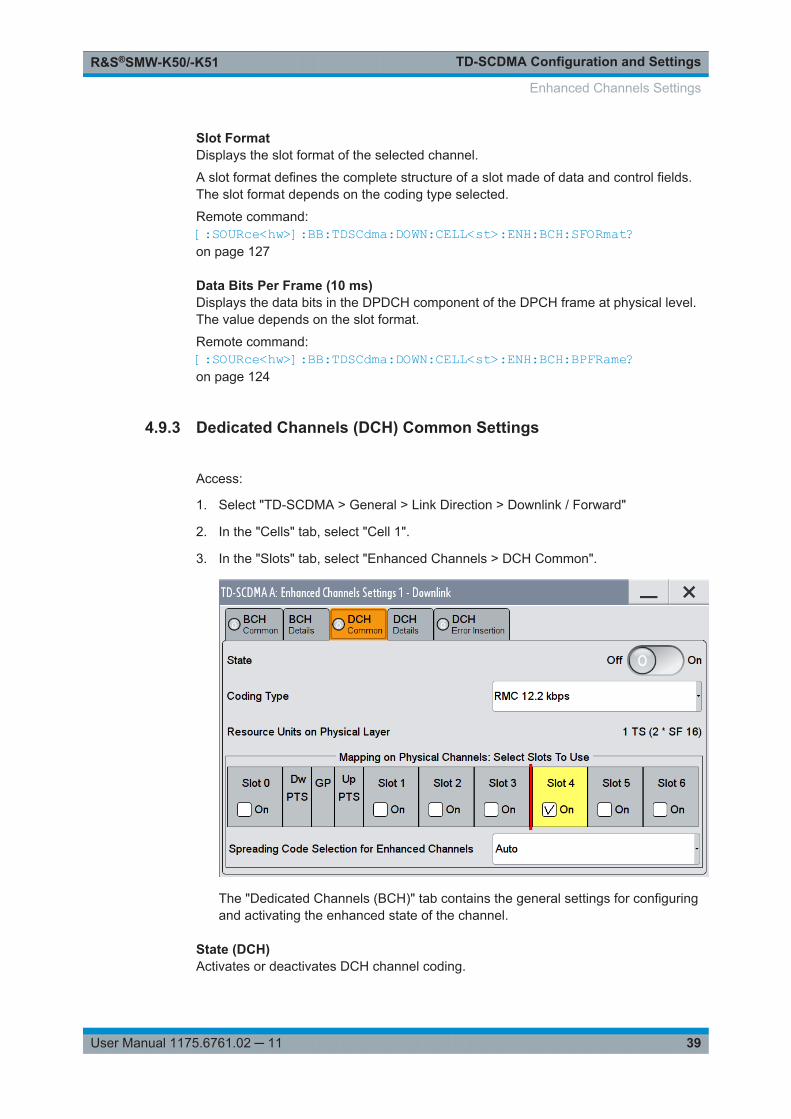
4.9.3 Dedicated Channels (DCH) Common Settings
Access:
1. Select "TD-SCDMA > General > Link Direction > Downlink / Forward"
2. In the "Cells" tab, select "Cell 1".
3. In the "Slots" tab, select "Enhanced Channels > DCH Common".
The "Dedicated Channels (BCH)" tab contains the general settings for configuringand activating the enhanced state of the channel.
State (DCH)Activates or deactivates DCH channel coding.
Enhanced Channels Settings
TD-SCDMA Configuration and SettingsR&S®SMW-K50/-K51
40User Manual 1175.6761.02 ─ 11
When the state is set to On, it activates the slots selected in the "Mapping On…" graphbelow. The number and configuration of the DPCHs is defined by the selected codingtype. State and slot format of the channels are preset. The data source is fixed to DCH.
Remote command: [:SOURce<hw>]:BB:TDSCdma:DOWN|UP:CELL<st>:ENH:DCH:STATeon page 123
Coding TypeSelects the channel coding.
The current TD-SCDMA specification defines four reference measurement channel(RMC) in the uplink. There are five measurement channel coding types in the downlink,which differ in the input data bit rate to be processed.
Additionally, special RMCs are defined for HSDPA, HSUPA, HS-SICH and PLCCH.
Select one of the predefined downlink RMCs to preconfigure the settings for UE testsaccording to 3GPP TS25.102, annex A.2.
Select one of the predefined uplink RMCs to preconfigure the settings for BS testsaccording to 3GPP TS25.142, annex A.
The selected coding type defines the number of slots selected in section "Mapping OnPhysical Channels: Select Slots To Use".
"RMC 12.2kbps"
Downlink/uplink 12.2 kbps measurement channel.
Note: If RMC12K2, RMC64K, RMC144K, or RMC384K are selectedfor the uplink, they are automatically converted to UP_RMCxxx.
"RMC 64 kbps"Downlink/uplink 64 kbps measurement channel
"RMC 144 kbps"Downlink/uplink 144 kbps measurement channel
"RMC 384 kbps"Downlink/uplink 384 kbps measurement channel
"RMC 2048 kbps"Downlink 2048 kbps measurement channel
"RMC PLCCH" Downlink RMC PLCCH channel (see RMC PLCCH Channel Settings)
"HSDPA" (downlink only)HSDPA reference measurement channel (see Chapter 4.10,"HSDPA/HSUPA Settings", on page 51).
"RMC HS-SICH"Uplink RMC for transport channel HS-SICH (seeChapter 4.9.7, "RMCHS-SICH Channel Settings", on page 48 )
"HSUPA" (uplink only)HSUPA reference measurement channel (see Chapter 4.10,"HSDPA/HSUPA Settings", on page 51).
"User" The channel settings are user-definable
Remote command: [:SOURce<hw>]:BB:TDSCdma:DOWN|UP:CELL<st>:ENH:DCH:TYPE on page 123
Enhanced Channels Settings
TD-SCDMA Configuration and SettingsR&S®SMW-K50/-K51
41User Manual 1175.6761.02 ─ 11
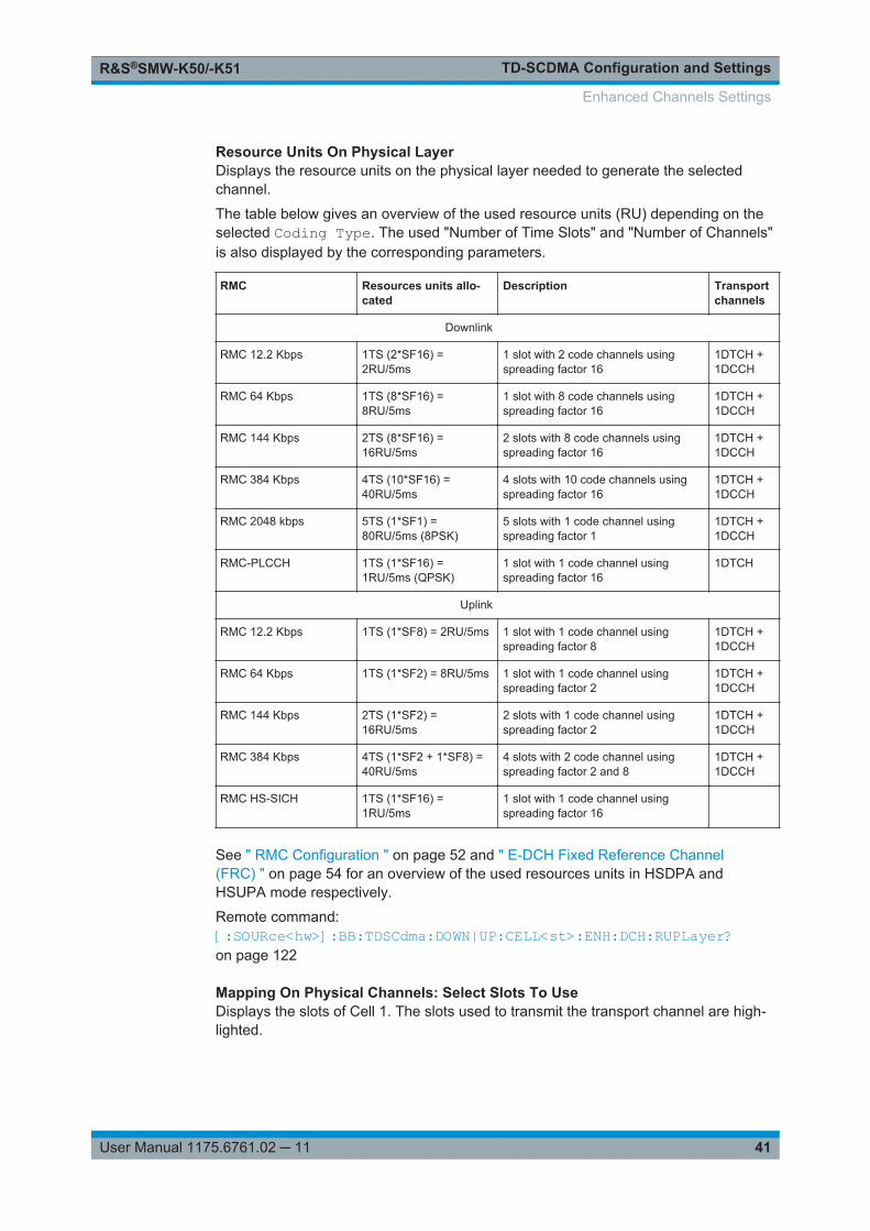
Resource Units On Physical LayerDisplays the resource units on the physical layer needed to generate the selectedchannel.
The table below gives an overview of the used resource units (RU) depending on theselected Coding Type. The used "Number of Time Slots" and "Number of Channels"is also displayed by the corresponding parameters.
RMC Resources units allo-cated
Description Transportchannels
Downlink
RMC 12.2 Kbps 1TS (2*SF16) =2RU/5ms
1 slot with 2 code channels usingspreading factor 16
1DTCH +1DCCH
RMC 64 Kbps 1TS (8*SF16) =8RU/5ms
1 slot with 8 code channels usingspreading factor 16
1DTCH +1DCCH
RMC 144 Kbps 2TS (8*SF16) =16RU/5ms
2 slots with 8 code channels usingspreading factor 16
1DTCH +1DCCH
RMC 384 Kbps 4TS (10*SF16) =40RU/5ms
4 slots with 10 code channels usingspreading factor 16
1DTCH +1DCCH
RMC 2048 kbps 5TS (1*SF1) =80RU/5ms (8PSK)
5 slots with 1 code channel usingspreading factor 1
1DTCH +1DCCH
RMC-PLCCH 1TS (1*SF16) =1RU/5ms (QPSK)
1 slot with 1 code channel usingspreading factor 16
1DTCH
Uplink
RMC 12.2 Kbps 1TS (1*SF8) = 2RU/5ms 1 slot with 1 code channel usingspreading factor 8
1DTCH +1DCCH
RMC 64 Kbps 1TS (1*SF2) = 8RU/5ms 1 slot with 1 code channel usingspreading factor 2
1DTCH +1DCCH
RMC 144 Kbps 2TS (1*SF2) =16RU/5ms
2 slots with 1 code channel usingspreading factor 2
1DTCH +1DCCH
RMC 384 Kbps 4TS (1*SF2 + 1*SF8) =40RU/5ms
4 slots with 2 code channel usingspreading factor 2 and 8
1DTCH +1DCCH
RMC HS-SICH 1TS (1*SF16) =1RU/5ms
1 slot with 1 code channel usingspreading factor 16
See " RMC Configuration " on page 52 and " E-DCH Fixed Reference Channel(FRC) " on page 54 for an overview of the used resources units in HSDPA andHSUPA mode respectively.
Remote command: [:SOURce<hw>]:BB:TDSCdma:DOWN|UP:CELL<st>:ENH:DCH:RUPLayer?on page 122
Mapping On Physical Channels: Select Slots To UseDisplays the slots of Cell 1. The slots used to transmit the transport channel are high-lighted.
Enhanced Channels Settings
TD-SCDMA Configuration and SettingsR&S®SMW-K50/-K51
42User Manual 1175.6761.02 ─ 11
The number of slots is determined by the selected coding type. If a slot is deactivated,another slot is activated automatically to keep the number of activated slotsunchanged.
Remote command: [:SOURce<hw>]:BB:TDSCdma:DOWN|UP:CELL<st>:ENH:DCH:SLOTstate<ch>on page 123
Spreading Code Selection for Enhanced ChannelsSelects the spreading code selection mode for the used transport channels.
"User" The spreading codes can be set manually.
"Auto" The spreading codes are distributed evenly over the slot domains inorder to ensure the minimum crest factor.
Remote command: [:SOURce<hw>]:BB:TDSCdma:DOWN|UP:CELL<st>:ENH:DCH:SCSModeon page 122
4.9.4 Dedicated Channels (DCH) Details Settings
Access:
1. Select "TD-SCDMA > General > Link Direction > Downlink / Forward".
2. In the "Cells" tab, select "Cell 1".
3. In the "Slots" tab, select "Enhanced Channels > DCH Details".
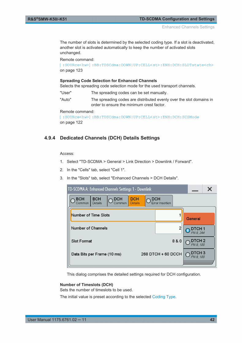
This dialog comprises the detailed settings required for DCH configuration.
Number of Timeslots (DCH)Sets the number of timeslots to be used.
The initial value is preset according to the selected Coding Type.
Enhanced Channels Settings
TD-SCDMA Configuration and SettingsR&S®SMW-K50/-K51
43User Manual 1175.6761.02 ─ 11
Remote command: [:SOURce<hw>]:BB:TDSCdma:DOWN|UP:CELL<st>:ENH:DCH:TSCounton page 123
Number of Channels (DCH)Sets the number of channels to be used.
The initial value is preset according to the selected Coding Type.
Remote command: [:SOURce<hw>]:BB:TDSCdma:DOWN|UP:CELL<st>:ENH:DCH:CCOunton page 118
Slot FormatDisplays the slot format of the selected channel.
A slot format defines the complete structure of a slot made of data and control fields.The slot format depends on the coding type selected.
Remote command: [:SOURce<hw>]:BB:TDSCdma:DOWN|UP:CELL<st>:ENH:DCH:SFORmat?on page 122
Data Bits Per Frame (10 ms)Displays the data bits in the DPDCH component of the DPCH frame at physical level.The value depends on the slot format.
Remote command: [:SOURce<hw>]:BB:TDSCdma:DOWN|UP:CELL<st>:ENH:DCH:BPFRame?on page 118
4.9.5 Transport Channel
Access:
1. Select "TD-SCDMA > General > Link Direction > Downlink / Forward"
2. In the "Cells" tab, select "Cell 1".
3. In the "Slots" tab, select:
a) "Enhanced Channels > BCH Details" orb) "Enhanced Settings > DCH Details".
Enhanced Channels Settings
TD-SCDMA Configuration and SettingsR&S®SMW-K50/-K51
44User Manual 1175.6761.02 ─ 11
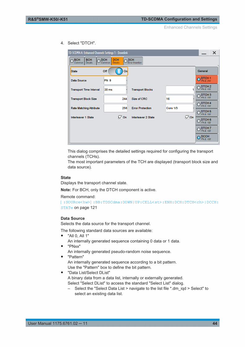
4. Select "DTCH".
This dialog comprises the detailed settings required for configuring the transportchannels (TCHs).The most important parameters of the TCH are displayed (transport block size anddata source).
StateDisplays the transport channel state.
Note: For BCH, only the DTCH component is active.
Remote command: [:SOURce<hw>]:BB:TDSCdma:DOWN|UP:CELL<st>:ENH:DCH:DTCH<ch>|DCCH:STATe on page 121
Data SourceSelects the data source for the transport channel.
The following standard data sources are available:● "All 0, All 1"
An internally generated sequence containing 0 data or 1 data.● "PNxx"
An internally generated pseudo-random noise sequence.● "Pattern"
An internally generated sequence according to a bit pattern.Use the "Pattern" box to define the bit pattern.
● "Data List/Select DList"A binary data from a data list, internally or externally generated.Select "Select DList" to access the standard "Select List" dialog.– Select the "Select Data List > navigate to the list file *.dm_iqd > Select" to
select an existing data list.
Enhanced Channels Settings
TD-SCDMA Configuration and SettingsR&S®SMW-K50/-K51
45User Manual 1175.6761.02 ─ 11
– Use the "New" and "Edit" functions to create internally new data list or to editan existing one.
– Use the standard "File Manager" function to transfer external data lists to theinstrument.
See also:● Section "Modulation Data" in the R&S SMW user manual.● Section "File and Data Management" in the R&S SMW user manual.● Section "Data List Editor" in the R&S SMW user manual
Remote command: [:SOURce<hw>]:BB:TDSCdma:DOWN:CELL<st>:ENH:BCH:DTCH:DATAon page 124[:SOURce<hw>]:BB:TDSCdma:DOWN|UP:CELL<st>:ENH:DCH:DTCH<ch>|DCCH:DATA on page 118[:SOURce<hw>]:BB:TDSCdma:DOWN:CELL<st>:ENH:BCH:DTCH:DATA:DSELecton page 125[:SOURce<hw>]:BB:TDSCdma:DOWN|UP:CELL<st>:ENH:DCH:DTCH<ch>|DCCH:DATA:DSELect on page 119[:SOURce<hw>]:BB:TDSCdma:DOWN:CELL<st>:ENH:BCH:DTCH:DATA:PATTernon page 126[:SOURce<hw>]:BB:TDSCdma:DOWN|UP:CELL<st>:ENH:DCH:DTCH<ch>|DCCH:DATA:PATTern on page 120
Transport Time IntervalDisplays the number of frames into which a TCH is divided. This setting also definesthe interleaver depth.
Remote command: [:SOURce<hw>]:BB:TDSCdma:DOWN:CELL<st>:ENH:BCH:DTCH:TTINterval?on page 127[:SOURce<hw>]:BB:TDSCdma:DOWN|UP:CELL<st>:ENH:DCH:DTCH<ch>|DCCH:TTINterval on page 122
Transport BlocksDisplays the number of transport blocks for the TCH.
Remote command: [:SOURce<hw>]:BB:TDSCdma:DOWN:CELL<st>:ENH:BCH:DTCH:TBCount?on page 126[:SOURce<hw>]:BB:TDSCdma:DOWN|UP:CELL<st>:ENH:DCH:DTCH<ch>|DCCH:TBCount on page 121
Transport Block SizeDisplays the size of the transport block at the channel coding input.
Remote command: [:SOURce<hw>]:BB:TDSCdma:DOWN:CELL<st>:ENH:BCH:DTCH:TBSize?on page 127[:SOURce<hw>]:BB:TDSCdma:DOWN|UP:CELL<st>:ENH:DCH:DTCH<ch>|DCCH:TBSize on page 121
Enhanced Channels Settings
TD-SCDMA Configuration and SettingsR&S®SMW-K50/-K51
46User Manual 1175.6761.02 ─ 11
Size Of CRCDisplays the type (length) of the CRC.
Remote command: [:SOURce<hw>]:BB:TDSCdma:DOWN:CELL<st>:ENH:BCH:DTCH:CRCSize?on page 124[:SOURce<hw>]:BB:TDSCdma:DOWN|UP:CELL<st>:ENH:DCH:DTCH<ch>|DCCH:CRCSize on page 118
Rate Matching AttributeDisplays the rate matching.
Remote command: [:SOURce<hw>]:BB:TDSCdma:DOWN:CELL<st>:ENH:BCH:DTCH:RMATtribute?on page 126[:SOURce<hw>]:BB:TDSCdma:DOWN|UP:CELL<st>:ENH:DCH:DTCH<ch>|DCCH:RMATtribute on page 120
Error ProtectionDisplays the error protection.
Remote command: [:SOURce<hw>]:BB:TDSCdma:DOWN:CELL<st>:ENH:BCH:DTCH:EPRotection?on page 126[:SOURce<hw>]:BB:TDSCdma:DOWN|UP:CELL<st>:ENH:DCH:DTCH<ch>|DCCH:EPRotection on page 120
Interleaver 1 StateActivates or deactivates the channel coding interleaver state 1 of the transport channel.Interleaver state 1 can be set independently in each TCH. Activation does not changethe symbol rate.
Remote command: [:SOURce<hw>]:BB:TDSCdma:DOWN:CELL<st>:ENH:BCH:DTCH:IONEon page 120[:SOURce<hw>]:BB:TDSCdma:DOWN|UP:CELL<st>:ENH:DCH:DTCH<ch>|DCCH:IONE on page 120
Interleaver 2 StateActivates or deactivates the channel coding interleaver state 2 off all the transportchannels. Interleaver state 2 can only be set for all the TCHs together. Activation doesnot change the symbol rate.
Remote command: [:SOURce<hw>]:BB:TDSCdma:DOWN:CELL<st>:ENH:BCH:DTCH:ITWOon page 120[:SOURce<hw>]:BB:TDSCdma:DOWN|UP:CELL<st>:ENH:DCH:DTCH<ch>|DCCH:ITWO on page 120
Enhanced Channels Settings
TD-SCDMA Configuration and SettingsR&S®SMW-K50/-K51
47User Manual 1175.6761.02 ─ 11
4.9.6 RMC PLCCH Channel Settings
Access:
1. Select "TD-SCDMA > General > Link Direction > Downlink / Forward".
2. In the "Cells" tab, select "Cell 1".
3. In the "Slots" tab, select "Enhanced Channels > DCH Common".
4. Select "Coding Type > RMC PLCCH".
5. Select "DCH Details".
6. Select "Information Bits".
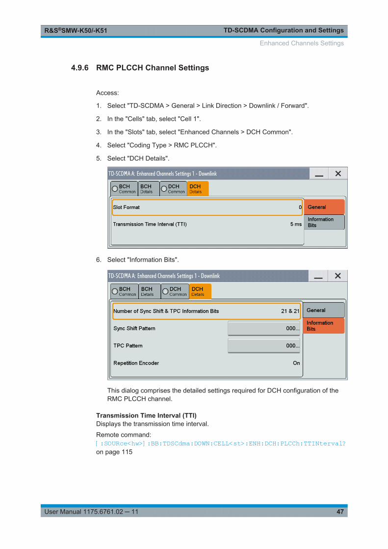
This dialog comprises the detailed settings required for DCH configuration of theRMC PLCCH channel.
Transmission Time Interval (TTI)Displays the transmission time interval.
Remote command: [:SOURce<hw>]:BB:TDSCdma:DOWN:CELL<st>:ENH:DCH:PLCCh:TTINterval?on page 115
Enhanced Channels Settings
TD-SCDMA Configuration and SettingsR&S®SMW-K50/-K51
48User Manual 1175.6761.02 ─ 11
Number of Sync Shift&TPC Information BitsDisplays the number of information bits used for sync shift and TPC. The RMC PLCCHdoe not contains data bits.
Remote command: n.a.
Sync Shift PatternSets the sync shift pattern. The pattern length is 21 bits.
Remote command: [:SOURce<hw>]:BB:TDSCdma:DOWN:CELL<st>:ENH:DCH:PLCCh:SSPatternon page 114
TPC PatternSets the TPC pattern. The pattern length is 21 bits.
Remote command: [:SOURce<hw>]:BB:TDSCdma:DOWN:CELL<st>:ENH:DCH:PLCCh:TPCPatternon page 115
Repetition EncoderDisplays the state of the repetition encoder.
Remote command: n.a.
4.9.7 RMC HS-SICH Channel Settings
1. To access this dialog select "TD-SCDMA > General > Link Direction" > "Uplink /Reverse"
2. In the "Cells" tab, select "Cell 1".
3. In the "Slots" tab, select "Enhanced Channels > DCH Common".
4. Select "Coding Type > RMC HS-SICH".
Enhanced Channels Settings
TD-SCDMA Configuration and SettingsR&S®SMW-K50/-K51
49User Manual 1175.6761.02 ─ 11
5. Select "DCH Details"
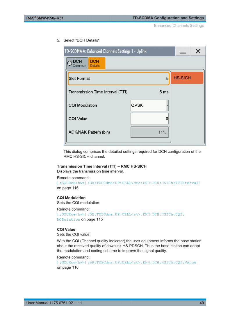
This dialog comprises the detailed settings required for DCH configuration of theRMC HS-SICH channel.
Transmission Time Interval (TTI) – RMC HS-SICHDisplays the transmission time interval.
Remote command: [:SOURce<hw>]:BB:TDSCdma:UP:CELL<st>:ENH:DCH:HSICh:TTINterval?on page 116
CQI ModulationSets the CQI modulation.
Remote command: [:SOURce<hw>]:BB:TDSCdma:UP:CELL<st>:ENH:DCH:HSICh:CQI:MODulation on page 115
CQI ValueSets the CQI value.
With the CQI (Channel quality indicator),the user equipment informs the base stationabout the received quality of downlink HS-PDSCH. Thus the base station can adaptthe modulation and coding scheme to improve the signal quality.
Remote command: [:SOURce<hw>]:BB:TDSCdma:UP:CELL<st>:ENH:DCH:HSICh:CQI:VALueon page 116
Enhanced Channels Settings
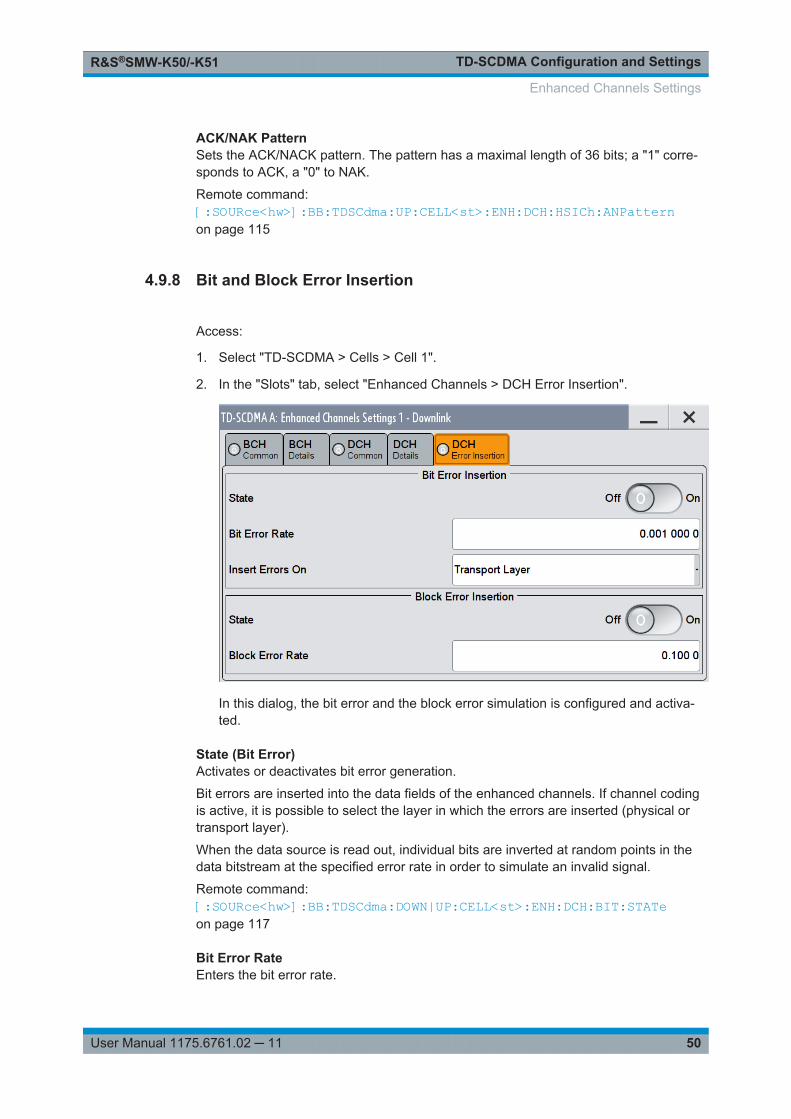
TD-SCDMA Configuration and SettingsR&S®SMW-K50/-K51
50User Manual 1175.6761.02 ─ 11
ACK/NAK PatternSets the ACK/NACK pattern. The pattern has a maximal length of 36 bits; a "1" corre-sponds to ACK, a "0" to NAK.
Remote command: [:SOURce<hw>]:BB:TDSCdma:UP:CELL<st>:ENH:DCH:HSICh:ANPatternon page 115
4.9.8 Bit and Block Error Insertion
Access:
1. Select "TD-SCDMA > Cells > Cell 1".
2. In the "Slots" tab, select "Enhanced Channels > DCH Error Insertion".
In this dialog, the bit error and the block error simulation is configured and activa-ted.
State (Bit Error)Activates or deactivates bit error generation.
Bit errors are inserted into the data fields of the enhanced channels. If channel codingis active, it is possible to select the layer in which the errors are inserted (physical ortransport layer).
When the data source is read out, individual bits are inverted at random points in thedata bitstream at the specified error rate in order to simulate an invalid signal.
Remote command: [:SOURce<hw>]:BB:TDSCdma:DOWN|UP:CELL<st>:ENH:DCH:BIT:STATeon page 117
Bit Error RateEnters the bit error rate.
Enhanced Channels Settings
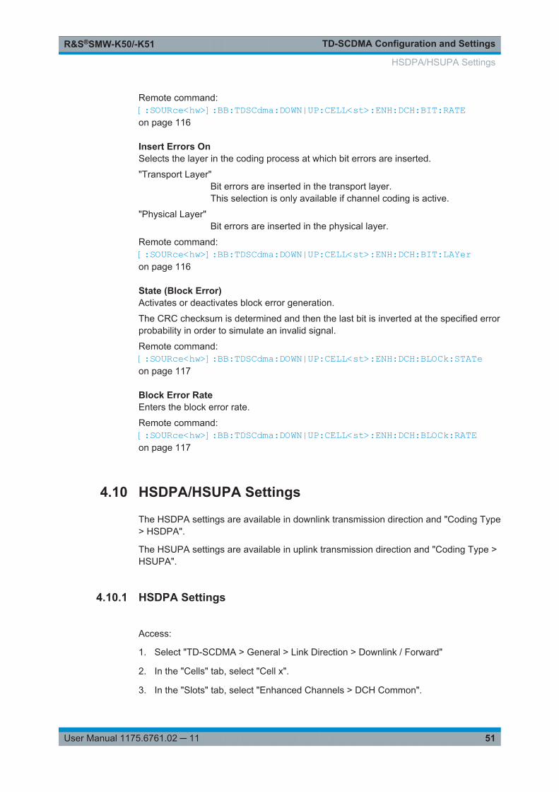
TD-SCDMA Configuration and SettingsR&S®SMW-K50/-K51
51User Manual 1175.6761.02 ─ 11
Remote command: [:SOURce<hw>]:BB:TDSCdma:DOWN|UP:CELL<st>:ENH:DCH:BIT:RATEon page 116
Insert Errors OnSelects the layer in the coding process at which bit errors are inserted.
"Transport Layer"Bit errors are inserted in the transport layer.This selection is only available if channel coding is active.
"Physical Layer"Bit errors are inserted in the physical layer.
Remote command: [:SOURce<hw>]:BB:TDSCdma:DOWN|UP:CELL<st>:ENH:DCH:BIT:LAYeron page 116
State (Block Error)Activates or deactivates block error generation.
The CRC checksum is determined and then the last bit is inverted at the specified errorprobability in order to simulate an invalid signal.
Remote command: [:SOURce<hw>]:BB:TDSCdma:DOWN|UP:CELL<st>:ENH:DCH:BLOCk:STATeon page 117
Block Error RateEnters the block error rate.
Remote command: [:SOURce<hw>]:BB:TDSCdma:DOWN|UP:CELL<st>:ENH:DCH:BLOCk:RATEon page 117
4.10 HSDPA/HSUPA Settings
The HSDPA settings are available in downlink transmission direction and "Coding Type> HSDPA".
The HSUPA settings are available in uplink transmission direction and "Coding Type >HSUPA".
4.10.1 HSDPA Settings
Access:
1. Select "TD-SCDMA > General > Link Direction > Downlink / Forward"
2. In the "Cells" tab, select "Cell x".
3. In the "Slots" tab, select "Enhanced Channels > DCH Common".
HSDPA/HSUPA Settings
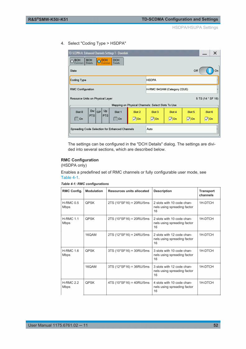
TD-SCDMA Configuration and SettingsR&S®SMW-K50/-K51
52User Manual 1175.6761.02 ─ 11
4. Select "Coding Type > HSDPA"
The settings can be configured in the "DCH Details" dialog. The settings are divi-ded into several sections, which are described below.
RMC Configuration(HSDPA only)
Enables a predefined set of RMC channels or fully configurable user mode, seeTable 4-1.Table 4-1: RMC configurations
RMC Config. Modulation Resources units allocated Description Transportchannels
H-RMC 0.5Mbps
QPSK 2TS (10*SF16) = 20RU/5ms 2 slots with 10 code chan-nels using spreading factor16
1H-DTCH
H-RMC 1.1Mbps
QPSK 2TS (10*SF16) = 20RU/5ms 2 slots with 10 code chan-nels using spreading factor16
1H-DTCH
16QAM 2TS (12*SF16) = 24RU/5ms 2 slots with 12 code chan-nels using spreading factor16
1H-DTCH
H-RMC 1.6Mbps
QPSK 3TS (10*SF16) = 30RU/5ms 3 slots with 10 code chan-nels using spreading factor16
1H-DTCH
16QAM 3TS (12*SF16) = 36RU/5ms 3 slots with 12 code chan-nels using spreading factor16
1H-DTCH
H-RMC 2.2Mbps
QPSK 4TS (10*SF16) = 40RU/5ms 4 slots with 10 code chan-nels using spreading factor16
1H-DTCH
HSDPA/HSUPA Settings

TD-SCDMA Configuration and SettingsR&S®SMW-K50/-K51
53User Manual 1175.6761.02 ─ 11
RMC Config. Modulation Resources units allocated Description Transportchannels
16QAM 4TS (12*SF16) = 48RU/5ms 4 slots with 12 code chan-nels using spreading factor16
1H-DTCH
H-RMC 2.8Mbps
QPSK 5TS (10*SF16) = 50RU/5ms 5 slots with 10 code chan-nels using spreading factor16
1H-DTCH
16QAM 5TS (12*SF16) = 50RU/5ms 5 slots with 12 code chan-nels using spreading factor16
1H-DTCH
H-RMC64QAM
64QAM (Cat-egory 16UE)
3TS (14*SF16) = 42RU/5ms 3 slots with 14 code chan-nels using spreading factor16
1H-DTCH
64QAM (Cat-egory 19UE)
5TS (14*SF16) = 70RU/5ms 5 slots with 14 code chan-nels using spreading factor16
1H-DTCH
64QAM (Cat-egory 22UE)
5TS (14*SF16) = 70RU/5ms 5 slots with 14 code chan-nels using spreading factor16
1H-DTCH
User - - - -
Several parameters are automatically set, depending on the selected RMC.
However, it is also possible to change these parameters.
In this case, the value of the parameter "RMC Configuration" is automatically set to"User".
Remote command: [:SOURce<hw>]:BB:TDSCdma:DOWN:CELL<st>:ENH:DCH:HSDPA:RMCon page 147
4.10.2 HSUPA Settings
Access:
1. Select "TD-SCDMA > General > Link Direction > Uplink / Reverse"
2. In the "Cells" tab, select "Cell x".
3. In the "Slots" tab, select "Enhanced Channels > DCH Common ".
HSDPA/HSUPA Settings
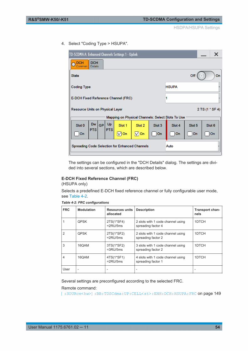
TD-SCDMA Configuration and SettingsR&S®SMW-K50/-K51
54User Manual 1175.6761.02 ─ 11
4. Select "Coding Type > HSUPA".
The settings can be configured in the "DCH Details" dialog. The settings are divi-ded into several sections, which are described below.
E-DCH Fixed Reference Channel (FRC)(HSUPA only)
Selects a predefined E-DCH fixed reference channel or fully configurable user mode,see Table 4-2.Table 4-2: FRC configurations
FRC Modulation Resources unitsallocated
Description Transport chan-nels
1 QPSK 2TS(1*SF4)=2RU/5ms
2 slots with 1 code channel usingspreading factor 4
1DTCH
2 QPSK 2TS(1*SF2)=2RU/5ms
2 slots with 1 code channel usingspreading factor 2
1DTCH
3 16QAM 3TS(1*SF2)=3RU/5ms
3 slots with 1 code channel usingspreading factor 2
1DTCH
4 16QAM 4TS(1*SF1)=2RU/5ms
4 slots with 1 code channel usingspreading factor 1
1DTCH
User - - - -
Several settings are preconfigured according to the selected FRC.
Remote command: [:SOURce<hw>]:BB:TDSCdma:UP:CELL<st>:ENH:DCH:HSUPA:FRC on page 149
HSDPA/HSUPA Settings
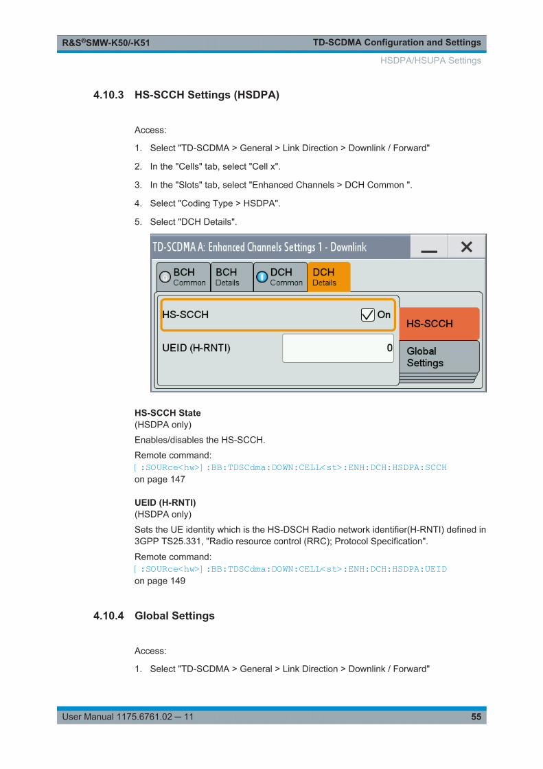
TD-SCDMA Configuration and SettingsR&S®SMW-K50/-K51
55User Manual 1175.6761.02 ─ 11
4.10.3 HS-SCCH Settings (HSDPA)
Access:
1. Select "TD-SCDMA > General > Link Direction > Downlink / Forward"
2. In the "Cells" tab, select "Cell x".
3. In the "Slots" tab, select "Enhanced Channels > DCH Common ".
4. Select "Coding Type > HSDPA".
5. Select "DCH Details".
HS-SCCH State(HSDPA only)
Enables/disables the HS-SCCH.
Remote command: [:SOURce<hw>]:BB:TDSCdma:DOWN:CELL<st>:ENH:DCH:HSDPA:SCCHon page 147
UEID (H-RNTI)(HSDPA only)
Sets the UE identity which is the HS-DSCH Radio network identifier(H-RNTI) defined in3GPP TS25.331, "Radio resource control (RRC); Protocol Specification".
Remote command: [:SOURce<hw>]:BB:TDSCdma:DOWN:CELL<st>:ENH:DCH:HSDPA:UEIDon page 149
4.10.4 Global Settings
Access:
1. Select "TD-SCDMA > General > Link Direction > Downlink / Forward"
HSDPA/HSUPA Settings
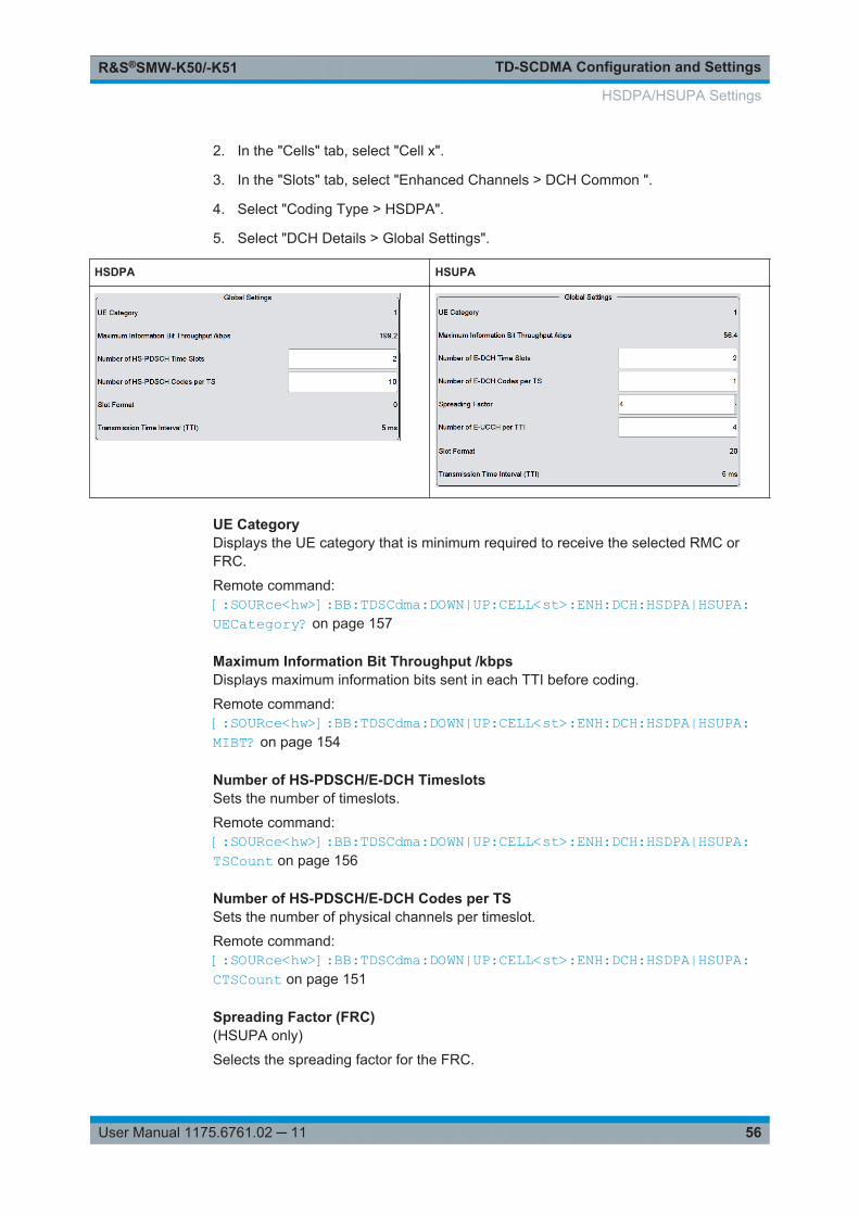
TD-SCDMA Configuration and SettingsR&S®SMW-K50/-K51
56User Manual 1175.6761.02 ─ 11
2. In the "Cells" tab, select "Cell x".
3. In the "Slots" tab, select "Enhanced Channels > DCH Common ".
4. Select "Coding Type > HSDPA".
5. Select "DCH Details > Global Settings".
HSDPA HSUPA
UE CategoryDisplays the UE category that is minimum required to receive the selected RMC orFRC.
Remote command: [:SOURce<hw>]:BB:TDSCdma:DOWN|UP:CELL<st>:ENH:DCH:HSDPA|HSUPA:UECategory? on page 157
Maximum Information Bit Throughput /kbpsDisplays maximum information bits sent in each TTI before coding.
Remote command: [:SOURce<hw>]:BB:TDSCdma:DOWN|UP:CELL<st>:ENH:DCH:HSDPA|HSUPA:MIBT? on page 154
Number of HS-PDSCH/E-DCH TimeslotsSets the number of timeslots.
Remote command: [:SOURce<hw>]:BB:TDSCdma:DOWN|UP:CELL<st>:ENH:DCH:HSDPA|HSUPA:TSCount on page 156
Number of HS-PDSCH/E-DCH Codes per TSSets the number of physical channels per timeslot.
Remote command: [:SOURce<hw>]:BB:TDSCdma:DOWN|UP:CELL<st>:ENH:DCH:HSDPA|HSUPA:CTSCount on page 151
Spreading Factor (FRC)(HSUPA only)
Selects the spreading factor for the FRC.
HSDPA/HSUPA Settings
TD-SCDMA Configuration and SettingsR&S®SMW-K50/-K51
57User Manual 1175.6761.02 ─ 11
Remote command: [:SOURce<hw>]:BB:TDSCdma:UP:CELL<st>:ENH:DCH:HSUPA:SFACtoron page 150
Number of E-UCCH per TTI(HSUPA only)
Sets the number of E-UCCH channels per TTI.
Remote command: [:SOURce<hw>]:BB:TDSCdma:UP:CELL<st>:ENH:DCH:HSUPA:EUCTtion page 149
Slot FormatDisplays the slot format of the selected channel.
A slot format defines the complete structure of a slot made of data and control fields.The slot format depends on the coding type selected.
Remote command: [:SOURce<hw>]:BB:TDSCdma:DOWN|UP:CELL<st>:ENH:DCH:HSDPA|HSUPA:SFORmat? on page 156
Transmission Time Interval (TTI)Displays the transmission time interval (TTI).
Remote command: [:SOURce<hw>]:BB:TDSCdma:DOWN|UP:CELL<st>:ENH:DCH:HSDPA|HSUPA:TTINterval? on page 157
4.10.5 Coding Configuration
Access:
1. Select "TD-SCDMA > General > Link Direction > Downlink / Forward"
2. In the "Cells" tab, select "Cell x".
3. In the "Slots" tab, select "Enhanced Channels > DCH Common ".
4. Select "Coding Type > HSDPA".
5. Select "DCH Details > Coding Configuration".
HSDPA/HSUPA Settings
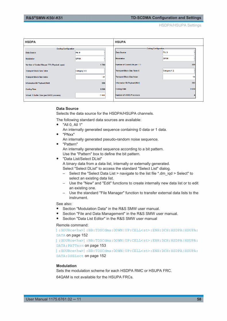
TD-SCDMA Configuration and SettingsR&S®SMW-K50/-K51
58User Manual 1175.6761.02 ─ 11
HSDPA HSUPA
Data SourceSelects the data source for the HSDPA/HSUPA channels.
The following standard data sources are available:● "All 0, All 1"
An internally generated sequence containing 0 data or 1 data.● "PNxx"
An internally generated pseudo-random noise sequence.● "Pattern"
An internally generated sequence according to a bit pattern.Use the "Pattern" box to define the bit pattern.
● "Data List/Select DList"A binary data from a data list, internally or externally generated.Select "Select DList" to access the standard "Select List" dialog.– Select the "Select Data List > navigate to the list file *.dm_iqd > Select" to
select an existing data list.– Use the "New" and "Edit" functions to create internally new data list or to edit
an existing one.– Use the standard "File Manager" function to transfer external data lists to the
instrument.See also:● Section "Modulation Data" in the R&S SMW user manual.● Section "File and Data Management" in the R&S SMW user manual.● Section "Data List Editor" in the R&S SMW user manual
Remote command: [:SOURce<hw>]:BB:TDSCdma:DOWN|UP:CELL<st>:ENH:DCH:HSDPA|HSUPA:DATA on page 152[:SOURce<hw>]:BB:TDSCdma:DOWN|UP:CELL<st>:ENH:DCH:HSDPA|HSUPA:DATA:PATTern on page 153[:SOURce<hw>]:BB:TDSCdma:DOWN|UP:CELL<st>:ENH:DCH:HSDPA|HSUPA:DATA:DSELect on page 152
ModulationSets the modulation scheme for each HSDPA RMC or HSUPA FRC.
64QAM is not available for the HSUPA FRCs.
HSDPA/HSUPA Settings
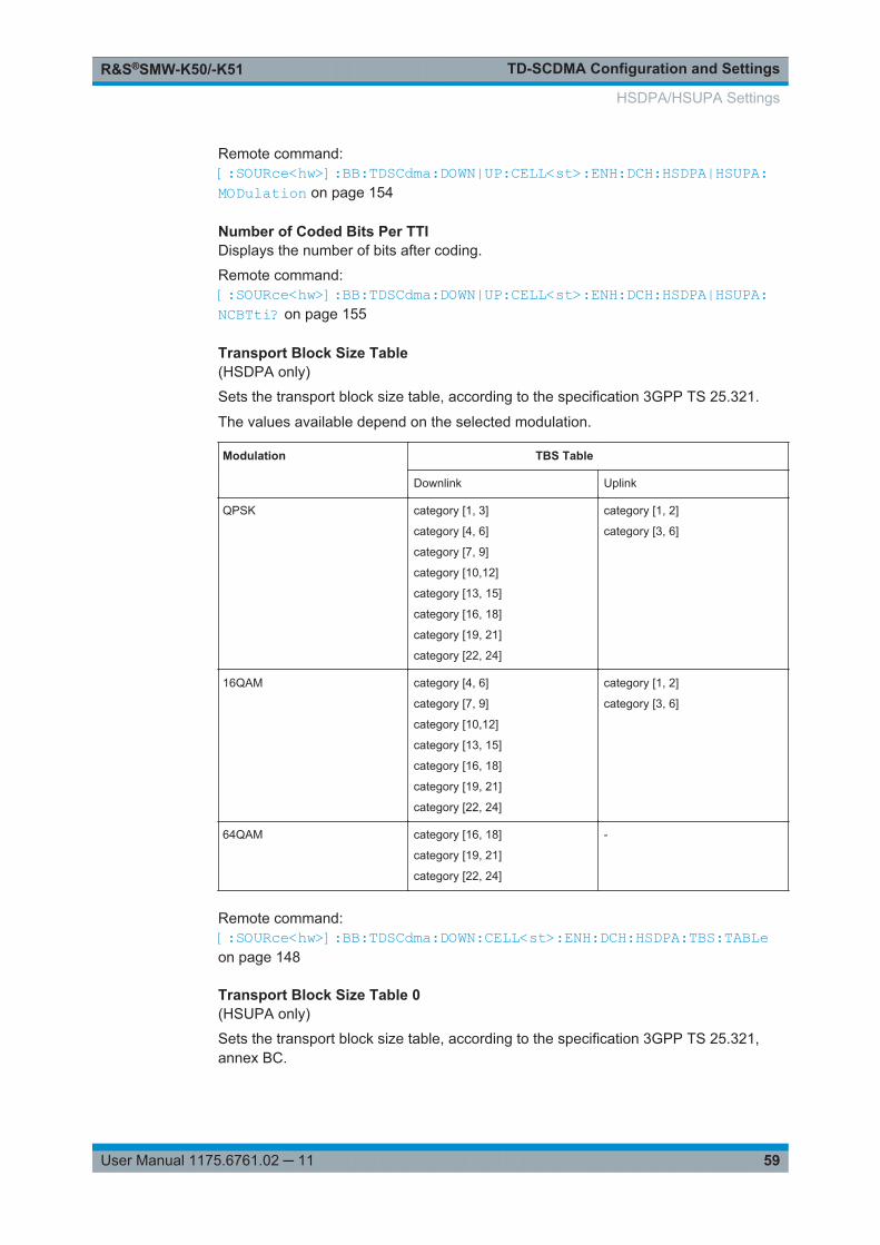
TD-SCDMA Configuration and SettingsR&S®SMW-K50/-K51
59User Manual 1175.6761.02 ─ 11
Remote command: [:SOURce<hw>]:BB:TDSCdma:DOWN|UP:CELL<st>:ENH:DCH:HSDPA|HSUPA:MODulation on page 154
Number of Coded Bits Per TTIDisplays the number of bits after coding.
Remote command: [:SOURce<hw>]:BB:TDSCdma:DOWN|UP:CELL<st>:ENH:DCH:HSDPA|HSUPA:NCBTti? on page 155
Transport Block Size Table(HSDPA only)
Sets the transport block size table, according to the specification 3GPP TS 25.321.
The values available depend on the selected modulation.
Modulation TBS Table
Downlink Uplink
QPSK category [1, 3]
category [4, 6]
category [7, 9]
category [10,12]
category [13, 15]
category [16, 18]
category [19, 21]
category [22, 24]
category [1, 2]
category [3, 6]
16QAM category [4, 6]
category [7, 9]
category [10,12]
category [13, 15]
category [16, 18]
category [19, 21]
category [22, 24]
category [1, 2]
category [3, 6]
64QAM category [16, 18]
category [19, 21]
category [22, 24]
-
Remote command: [:SOURce<hw>]:BB:TDSCdma:DOWN:CELL<st>:ENH:DCH:HSDPA:TBS:TABLeon page 148
Transport Block Size Table 0(HSUPA only)
Sets the transport block size table, according to the specification 3GPP TS 25.321,annex BC.
HSDPA/HSUPA Settings
TD-SCDMA Configuration and SettingsR&S®SMW-K50/-K51
60User Manual 1175.6761.02 ─ 11
Remote command: [:SOURce<hw>]:BB:TDSCdma:UP:CELL<st>:ENH:DCH:HSUPA:TBS:TABLeon page 151
Transport Block Size IndexSelects the index for the corresponding table, as described in 3GPP TS 25.321.
Remote command: [:SOURce<hw>]:BB:TDSCdma:DOWN|UP:CELL<st>:ENH:DCH:HSDPA|HSUPA:TBS:INDex on page 156
Information Bit Payload (Ninf)Displays the payload of the information bit. i.e. transport block size. This value deter-mines the number of transport layer bits sent in each TTI before coding.
Remote command: [:SOURce<hw>]:BB:TDSCdma:DOWN|UP:CELL<st>:ENH:DCH:HSDPA|HSUPA:BPAYload? on page 151
Coding RateDisplays the resulting coding rate.
The coding rate is calculated as a relation between the Information Bit Payloadand "Number of Coded Bits per TTI".
Remote command: [:SOURce<hw>]:BB:TDSCdma:DOWN|UP:CELL<st>:ENH:DCH:HSDPA|HSUPA:CRATe? on page 151
Virtual IR Buffer Size (Per HARQ process)(HSDPA only)
Sets the size of the virtual IR buffer.
Remote command: [:SOURce<hw>]:BB:TDSCdma:DOWN:CELL<st>:ENH:DCH:HSDPA:VIBSizeon page 149
4.10.6 Signal Structure
Access:
1. Select "TD-SCDMA > General > Link Direction > Downlink / Forward"
2. In the "Cells" tab, select "Cell x".
3. In the "Slots" tab, select "Enhanced Channels > DCH Common ".
4. Select "Coding Type > HSDPA".
5. Select "DCH Details > Signal Structure".
HSDPA/HSUPA Settings
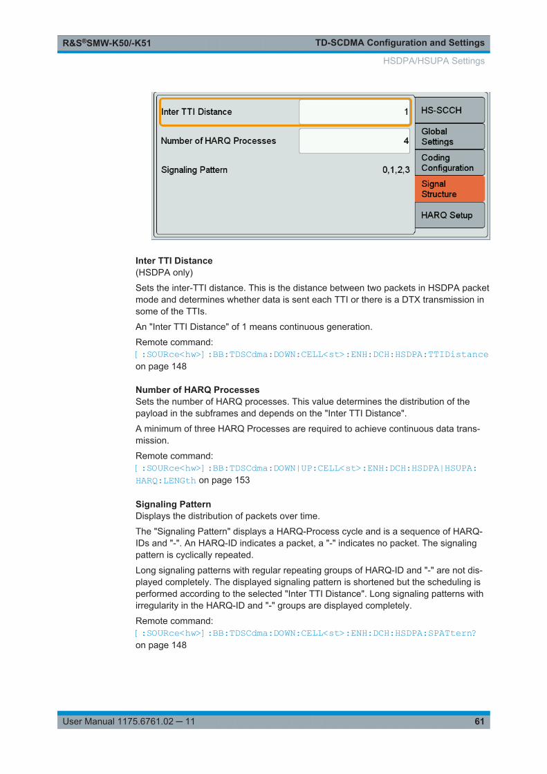
TD-SCDMA Configuration and SettingsR&S®SMW-K50/-K51
61User Manual 1175.6761.02 ─ 11
Inter TTI Distance(HSDPA only)
Sets the inter-TTI distance. This is the distance between two packets in HSDPA packetmode and determines whether data is sent each TTI or there is a DTX transmission insome of the TTIs.
An "Inter TTI Distance" of 1 means continuous generation.
Remote command: [:SOURce<hw>]:BB:TDSCdma:DOWN:CELL<st>:ENH:DCH:HSDPA:TTIDistanceon page 148
Number of HARQ ProcessesSets the number of HARQ processes. This value determines the distribution of thepayload in the subframes and depends on the "Inter TTI Distance".
A minimum of three HARQ Processes are required to achieve continuous data trans-mission.
Remote command: [:SOURce<hw>]:BB:TDSCdma:DOWN|UP:CELL<st>:ENH:DCH:HSDPA|HSUPA:HARQ:LENGth on page 153
Signaling PatternDisplays the distribution of packets over time.
The "Signaling Pattern" displays a HARQ-Process cycle and is a sequence of HARQ-IDs and "-". An HARQ-ID indicates a packet, a "-" indicates no packet. The signalingpattern is cyclically repeated.
Long signaling patterns with regular repeating groups of HARQ-ID and "-" are not dis-played completely. The displayed signaling pattern is shortened but the scheduling isperformed according to the selected "Inter TTI Distance". Long signaling patterns withirregularity in the HARQ-ID and "-" groups are displayed completely.
Remote command: [:SOURce<hw>]:BB:TDSCdma:DOWN:CELL<st>:ENH:DCH:HSDPA:SPATtern?on page 148
HSDPA/HSUPA Settings
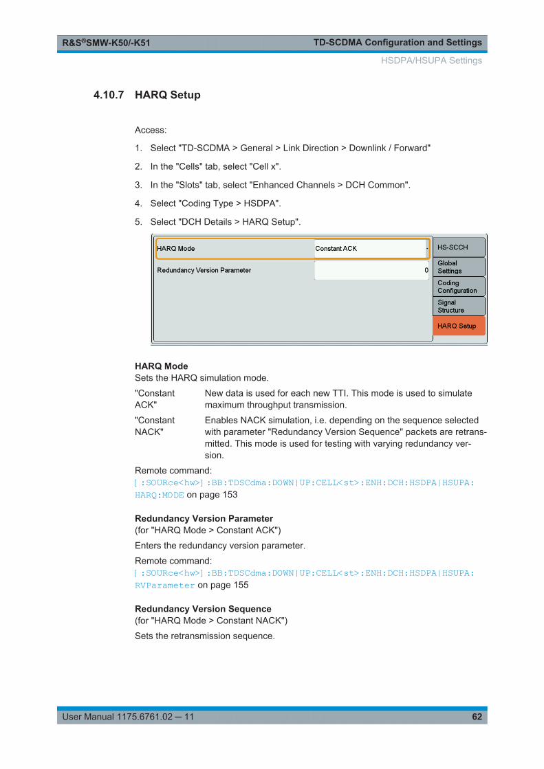
TD-SCDMA Configuration and SettingsR&S®SMW-K50/-K51
62User Manual 1175.6761.02 ─ 11
4.10.7 HARQ Setup
Access:
1. Select "TD-SCDMA > General > Link Direction > Downlink / Forward"
2. In the "Cells" tab, select "Cell x".
3. In the "Slots" tab, select "Enhanced Channels > DCH Common".
4. Select "Coding Type > HSDPA".
5. Select "DCH Details > HARQ Setup".
HARQ ModeSets the HARQ simulation mode.
"ConstantACK"
New data is used for each new TTI. This mode is used to simulatemaximum throughput transmission.
"ConstantNACK"
Enables NACK simulation, i.e. depending on the sequence selectedwith parameter "Redundancy Version Sequence" packets are retrans-mitted. This mode is used for testing with varying redundancy ver-sion.
Remote command: [:SOURce<hw>]:BB:TDSCdma:DOWN|UP:CELL<st>:ENH:DCH:HSDPA|HSUPA:HARQ:MODE on page 153
Redundancy Version Parameter(for "HARQ Mode > Constant ACK")
Enters the redundancy version parameter.
Remote command: [:SOURce<hw>]:BB:TDSCdma:DOWN|UP:CELL<st>:ENH:DCH:HSDPA|HSUPA:RVParameter on page 155
Redundancy Version Sequence(for "HARQ Mode > Constant NACK")
Sets the retransmission sequence.
HSDPA/HSUPA Settings
TD-SCDMA Configuration and SettingsR&S®SMW-K50/-K51
63User Manual 1175.6761.02 ─ 11
The sequence has a length of maximum 30 values, separated by commas. Thesequence length determines the maximum number of retransmissions. New data isretrieved from the data source after reaching the end of the sequence.
For HSUPA, this parameter is read-only.
Remote command: [:SOURce<hw>]:BB:TDSCdma:DOWN|UP:CELL<st>:ENH:DCH:HSDPA|HSUPA:RVSequence on page 155
Retransmission Sequence Number(for HSUPA and "HARQ Mode > Constant ACK")
Sets the retransmission sequence number.
The value is fixed to 0.
Remote command: [:SOURce<hw>]:BB:TDSCdma:UP:CELL<st>:ENH:DCH:HSUPA:RSNumber?on page 150
Retransmission Sequence(for HSUPA and "HARQ Mode > Constant NACK")
Sets the retransmission sequence.
Remote command: [:SOURce<hw>]:BB:TDSCdma:UP:CELL<st>:ENH:DCH:HSUPA:RSEQuenceon page 150
4.11 Slot Configuration
This "TD-SCDMA Cell/Slot..." dialog contains the parameters required for configuringthe cell of the selected slot, providing the channel table with graphical display of therespective channel.
4.11.1 Common Settings
1. To access this dialog, select "TD-SCDMA > Cells".
2. Select "Cell 1...Cell 4 ".
3. In the "Slots" tab, select "Slot 0...Slot 6".
Slot Configuration
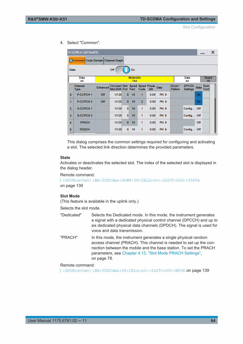
TD-SCDMA Configuration and SettingsR&S®SMW-K50/-K51
64User Manual 1175.6761.02 ─ 11
4. Select "Common".
This dialog comprises the common settings required for configuring and activatinga slot. The selected link direction determines the provided parameters.
StateActivates or deactivates the selected slot. The index of the selected slot is displayed inthe dialog header.
Remote command: [:SOURce<hw>]:BB:TDSCdma:DOWN|UP:CELL<st>:SLOT<ch0>:STATeon page 139
Slot Mode(This feature is available in the uplink only.)
Selects the slot mode.
"Dedicated" Selects the Dedicated mode. In this mode, the instrument generatesa signal with a dedicated physical control channel (DPCCH) and up tosix dedicated physical data channels (DPDCH). The signal is used forvoice and data transmission.
"PRACH" In this mode, the instrument generates a single physical randomaccess channel (PRACH). This channel is needed to set up the con-nection between the mobile and the base station. To set the PRACHparameters, see Chapter 4.13, "Slot Mode PRACH Settings",on page 78.
Remote command: [:SOURce<hw>]:BB:TDSCdma:UP:CELL<st>:SLOT<ch0>:MODE on page 139
Slot Configuration
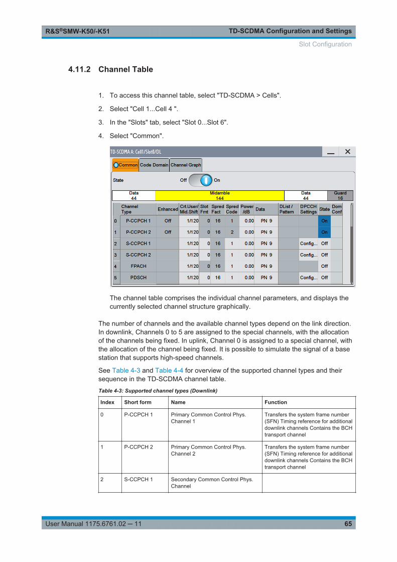
TD-SCDMA Configuration and SettingsR&S®SMW-K50/-K51
65User Manual 1175.6761.02 ─ 11
4.11.2 Channel Table
1. To access this channel table, select "TD-SCDMA > Cells".
2. Select "Cell 1...Cell 4 ".
3. In the "Slots" tab, select "Slot 0...Slot 6".
4. Select "Common".
The channel table comprises the individual channel parameters, and displays thecurrently selected channel structure graphically.
The number of channels and the available channel types depend on the link direction.In downlink, Channels 0 to 5 are assigned to the special channels, with the allocationof the channels being fixed. In uplink, Channel 0 is assigned to a special channel, withthe allocation of the channel being fixed. It is possible to simulate the signal of a basestation that supports high-speed channels.
See Table 4-3 and Table 4-4 for overview of the supported channel types and theirsequence in the TD-SCDMA channel table.
Table 4-3: Supported channel types (Downlink)
Index Short form Name Function
0 P-CCPCH 1 Primary Common Control Phys.Channel 1
Transfers the system frame number(SFN) Timing reference for additionaldownlink channels Contains the BCHtransport channel
1 P-CCPCH 2 Primary Common Control Phys.Channel 2
Transfers the system frame number(SFN) Timing reference for additionaldownlink channels Contains the BCHtransport channel
2 S-CCPCH 1 Secondary Common Control Phys.Channel
Slot Configuration

TD-SCDMA Configuration and SettingsR&S®SMW-K50/-K51
66User Manual 1175.6761.02 ─ 11
Index Short form Name Function
3 S-CCPCH 2 Secondary Common Control Phys.Channel
4 FPACH Fast Physical Access Channel
5 PDSCH Phys. Downlink Shared Channel
6-21 DPCH QPSK Dedicated Phys. Channel ModulationQPSK
Transfers the user data and the con-trol information
DPCH 8PSK Dedicated Phys. Channel Modulation8PSK
HS-SCCH 1 High-Speed Shared Control Channel1
HS-SCCH 2 High-Speed Shared Control Channel2
HS-PDSCH(QPSK)
High-Speed Phys. Downlink SharedChannel QPSK
HS-PDSCH(16QAM)
High-Speed Phys. Downlink SharedChannel 16 QAM
HS-PDSCH(64QAM)
High-Speed Phys. Downlink SharedChannel 64QAM
PLCCH Physical layer common control chan-nel
E-AGCH E-DCH Absolute Grant Channel
E-HICH E-DCH Hybrid ARQ Indicator Chan-nel
Table 4-4: Supported channel types (Uplink)
Index Short form Name Function
0 PUSCH Phys. Uplink Shared Channel
1-16 DPCH QPSK Dedicated Phys. Channel ModulationQPSK
DPCH 8PSK Dedicated Phys. Channel Modulation8PSK
HS-SICH High-Speed Shared InformationChannel
E-PUCH (QPSK) E-DCH Uplink Physical Channel(QPSK)
E-PUCH(16QAM)
E-DCH Uplink Physical Channel(16QAM)
E-RUCCH E-DCH Random Access Uplink Con-trol Channel
Slot Configuration
TD-SCDMA Configuration and SettingsR&S®SMW-K50/-K51
67User Manual 1175.6761.02 ─ 11
Channel NumberDisplays the consecutive channel numbers. The range depends on the selected trans-mission direction.
All available channels are displayed, even those that are inactive. Each channel is acti-vated/deactivated by the "State" button.
Remote command: n.a.
Channel TypeSelects the channel type.
In the uplink, the channel type is fixed for channel number 0.
In the downlink, the channel type is fixed for channel numbers 0 to 5.
For the remaining numbers, the choice lies between the relevant standard channelsand the high-speed channels (see Table 4-3 and Table 4-4).
Remote command: [:SOURce<hw>]:BB:TDSCdma:DOWN|UP:CELL<st>:SLOT<ch0>:CHANnel<us0>:TYPE on page 138
EnhancedDisplays the enhanced state. If the enhanced state is set to on, the channel codingcannot be changed.
Remote command: [:SOURce<hw>]:BB:TDSCdma:DOWN|UP:CELL<st>:SLOT<ch0>:CHANnel<us0>:ENHanced? on page 136
Crt.User/Mid.ShiftEnters the value for the user and displays the midamble shift.
Remote command: [:SOURce<hw>]:BB:TDSCdma:DOWN|UP:CELL<st>:SLOT<ch0>:CHANnel<us0>:USER on page 138
Slot FormatEnters the slot format for the selected channel.
The range of the values depends on the channel selected. For DPCH 8PSK channels,for example, the value range for the slot formats is 0 to 24.
A slot format defines the complete structure of a slot made of data and control fieldsand includes the symbol rate.
Parameters set via the slot format can subsequently be changed individually.
The structure of the channel currently selected is displayed in a graphic above thechannel table.
Remote command: [:SOURce<hw>]:BB:TDSCdma:DOWN|UP:CELL<st>:SLOT<ch0>:CHANnel<us0>:SFORmat on page 137
Slot Configuration
TD-SCDMA Configuration and SettingsR&S®SMW-K50/-K51
68User Manual 1175.6761.02 ─ 11
Sprd. Fact.Enters the spreading factor for the selected channel. The selection depends on thechannel type and interacts with the slot format.
Remote command: [:SOURce<hw>]:BB:TDSCdma:DOWN|UP:CELL<st>:SLOT<ch0>:CHANnel<us0>:SFACtor on page 137
Sprd. CodeEnters the spreading code for the selected channel. The code channel is spread withthe set spreading code. The range of values for the spreading code depends on thechannel type and the spreading factor. Depending on the channel type, the range ofvalues can be limited.
Remote command: [:SOURce<hw>]:BB:TDSCdma:DOWN|UP:CELL<st>:SLOT<ch0>:CHANnel<us0>:SCODe on page 137
Power/dBSets the channel power in dB.
The power entered is relative to the powers outputs of the other channels. If "AdjustTotal Power to 0 dB" is executed (top level of the TD-SCDMA dialog), all the powerdata is relative to 0 dB.
The value range is -80 dB to 0 dB.
Note: The maximum channel power of 0 dB applies to non-blanked channels (dutycycle 100%). With blanked channels, the maximum value can be increased to valuesgreater than 0 dB.Uset the parameter "Adjust Total Power" to increase the power to a maximum value of10*Log10(1/duty_cycle)
Remote command: [:SOURce<hw>]:BB:TDSCdma:DOWN|UP:CELL<st>:SLOT<ch0>:CHANnel<us0>:POWer on page 136
DataSelects data source.
The following standard data sources are available:● "All 0, All 1"
An internally generated sequence containing 0 data or 1 data.● "PNxx"
An internally generated pseudo-random noise sequence.● "Pattern"
An internally generated sequence according to a bit pattern.Use the "Pattern" box to define the bit pattern.
● "Data List/Select DList"A binary data from a data list, internally or externally generated.Select "Select DList" to access the standard "Select List" dialog.– Select the "Select Data List > navigate to the list file *.dm_iqd > Select" to
select an existing data list.
Slot Configuration
TD-SCDMA Configuration and SettingsR&S®SMW-K50/-K51
69User Manual 1175.6761.02 ─ 11
– Use the "New" and "Edit" functions to create internally new data list or to editan existing one.
– Use the standard "File Manager" function to transfer external data lists to theinstrument.
See also:● Section "Modulation Data" in the R&S SMW user manual.● Section "File and Data Management" in the R&S SMW user manual.● Section "Data List Editor" in the R&S SMW user manual
Remote command: [:SOURce<hw>]:BB:TDSCdma:DOWN|UP:CELL<st>:SLOT<ch0>:CHANnel<us0>:DATA on page 131[:SOURce<hw>]:BB:TDSCdma:DOWN|UP:CELL<st>:SLOT<ch0>:CHANnel<us0>:DATA:DSELect on page 132[:SOURce<hw>]:BB:TDSCdma:DOWN|UP:CELL<st>:SLOT<ch0>:CHANnel<us0>:DATA:PATTern on page 132
DPCCH SettingsAccesses the dialog for configuring the control fields of the selected channel.
The selected slot format predetermines the setting of the control fields.
So a change is also made to the control fields by changing the slot format and viceversa.
The dialog is described in Chapter 4.12, "DPCCH Settings", on page 71
Remote command: n.a.
StateActivates or deactivates the channel.
Remote command: [:SOURce<hw>]:BB:TDSCdma:DOWN|UP:CELL<st>:SLOT<ch0>:CHANnel<us0>:STATe on page 138
Dom. Conf.Displays whether the channel has a code domain conflict with one of the overlyingchannels (with lower channel number).
In case of conflict, a warning icon appears.You can find the current code domainassignment graphically displayed in the "Code Domain" tab (see Chapter 4.11.3,"Code Domain", on page 69).
Remote command: [:SOURce<hw>]:BB:TDSCdma:DOWN|UP:CELL<st>:SLOT<ch0>:DCONflict?on page 139
4.11.3 Code Domain
The channelization codes are taken from a code tree of hierarchical structure (see Fig-ure 4-1). The higher the spreading factor, the smaller the symbol rate and vice versa.
Slot Configuration
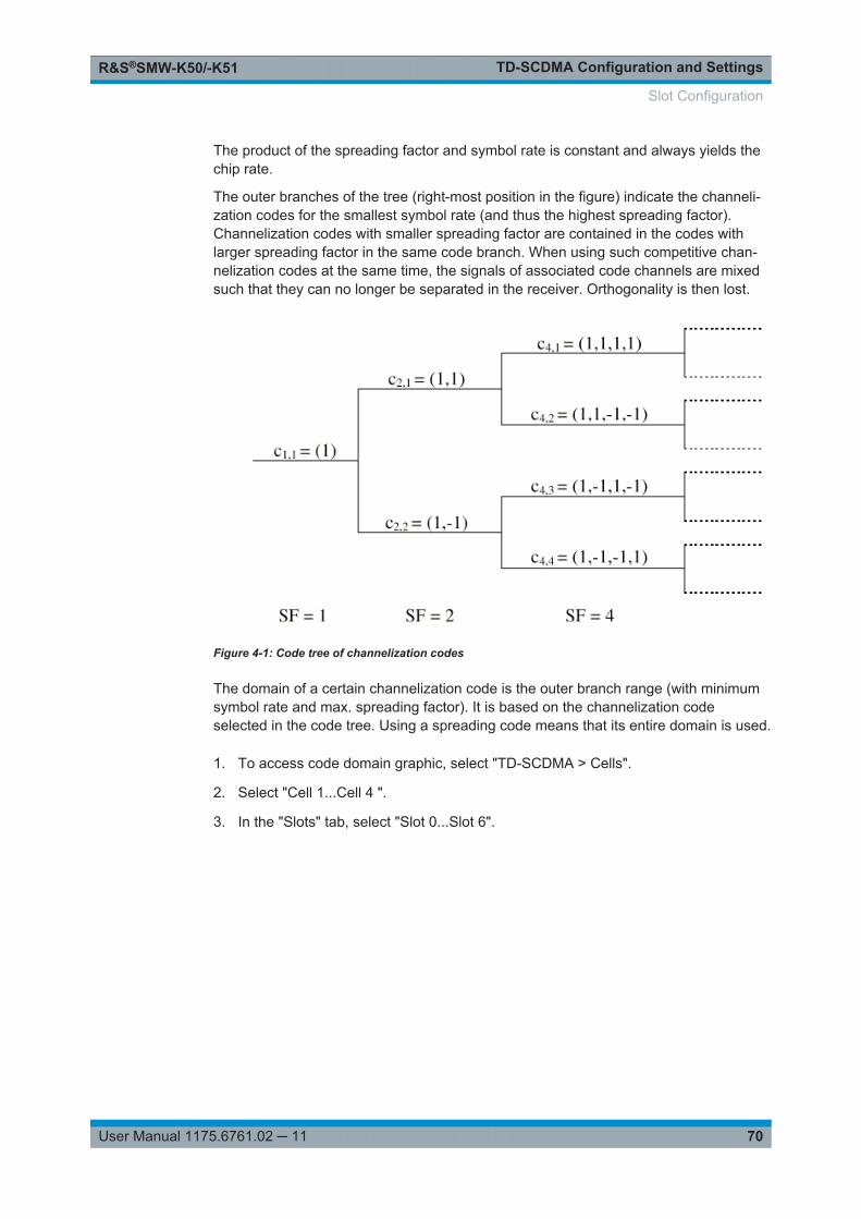
TD-SCDMA Configuration and SettingsR&S®SMW-K50/-K51
70User Manual 1175.6761.02 ─ 11
The product of the spreading factor and symbol rate is constant and always yields thechip rate.
The outer branches of the tree (right-most position in the figure) indicate the channeli-zation codes for the smallest symbol rate (and thus the highest spreading factor).Channelization codes with smaller spreading factor are contained in the codes withlarger spreading factor in the same code branch. When using such competitive chan-nelization codes at the same time, the signals of associated code channels are mixedsuch that they can no longer be separated in the receiver. Orthogonality is then lost.
Figure 4-1: Code tree of channelization codes
The domain of a certain channelization code is the outer branch range (with minimumsymbol rate and max. spreading factor). It is based on the channelization codeselected in the code tree. Using a spreading code means that its entire domain is used.
1. To access code domain graphic, select "TD-SCDMA > Cells".
2. Select "Cell 1...Cell 4 ".
3. In the "Slots" tab, select "Slot 0...Slot 6".
Slot Configuration
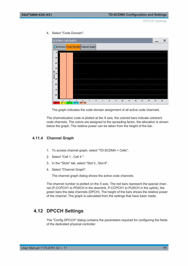
TD-SCDMA Configuration and SettingsR&S®SMW-K50/-K51
71User Manual 1175.6761.02 ─ 11
4. Select "Code Domain".
The graph indicates the code domain assignment of all active code channels.
The channelization code is plotted at the X axis, the colored bars indicate coherentcode channels. The colors are assigned to the spreading factor, the allocation is shownbelow the graph. The relative power can be taken from the height of the bar.
4.11.4 Channel Graph
1. To access channel graph, select "TD-SCDMA > Cells".
2. Select "Cell 1...Cell 4 ".
3. In the "Slots" tab, select "Slot 0...Slot 6".
4. Select "Channel Graph".
The channel graph dialog shows the active code channels.
The channel number is plotted on the X axis. The red bars represent the special chan-nel (P-CCPCH1 to PDSCH in the downlink, P-CCPCH1 to PUSCH in the uplink), thegreen bars the data channels (DPCH). The height of the bars shows the relative powerof the channel. The graph is calculated from the settings that have been made.
4.12 DPCCH Settings
The "Config DPCCH" dialog contains the parameters required for configuring the fieldsof the dedicated physical controller.
DPCCH Settings
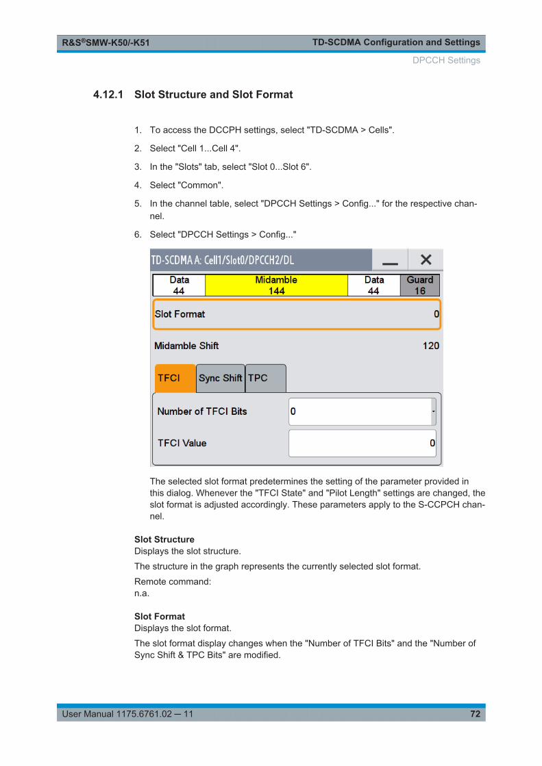
TD-SCDMA Configuration and SettingsR&S®SMW-K50/-K51
72User Manual 1175.6761.02 ─ 11
4.12.1 Slot Structure and Slot Format
1. To access the DCCPH settings, select "TD-SCDMA > Cells".
2. Select "Cell 1...Cell 4".
3. In the "Slots" tab, select "Slot 0...Slot 6".
4. Select "Common".
5. In the channel table, select "DPCCH Settings > Config..." for the respective chan-nel.
6. Select "DPCCH Settings > Config..."
The selected slot format predetermines the setting of the parameter provided inthis dialog. Whenever the "TFCI State" and "Pilot Length" settings are changed, theslot format is adjusted accordingly. These parameters apply to the S-CCPCH chan-nel.
Slot StructureDisplays the slot structure.
The structure in the graph represents the currently selected slot format.
Remote command: n.a.
Slot FormatDisplays the slot format.
The slot format display changes when the "Number of TFCI Bits" and the "Number ofSync Shift & TPC Bits" are modified.
DPCCH Settings
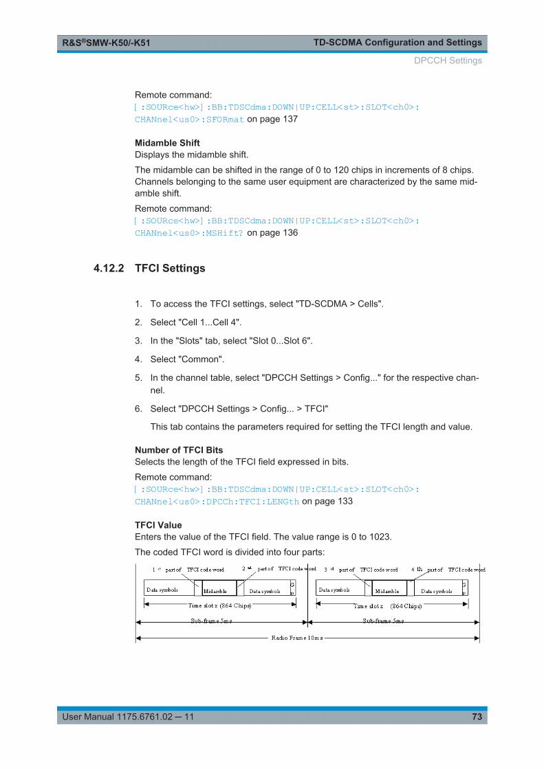
TD-SCDMA Configuration and SettingsR&S®SMW-K50/-K51
73User Manual 1175.6761.02 ─ 11
Remote command: [:SOURce<hw>]:BB:TDSCdma:DOWN|UP:CELL<st>:SLOT<ch0>:CHANnel<us0>:SFORmat on page 137
Midamble ShiftDisplays the midamble shift.
The midamble can be shifted in the range of 0 to 120 chips in increments of 8 chips.Channels belonging to the same user equipment are characterized by the same mid-amble shift.
Remote command: [:SOURce<hw>]:BB:TDSCdma:DOWN|UP:CELL<st>:SLOT<ch0>:CHANnel<us0>:MSHift? on page 136
4.12.2 TFCI Settings
1. To access the TFCI settings, select "TD-SCDMA > Cells".
2. Select "Cell 1...Cell 4".
3. In the "Slots" tab, select "Slot 0...Slot 6".
4. Select "Common".
5. In the channel table, select "DPCCH Settings > Config..." for the respective chan-nel.
6. Select "DPCCH Settings > Config... > TFCI"
This tab contains the parameters required for setting the TFCI length and value.
Number of TFCI BitsSelects the length of the TFCI field expressed in bits.
Remote command: [:SOURce<hw>]:BB:TDSCdma:DOWN|UP:CELL<st>:SLOT<ch0>:CHANnel<us0>:DPCCh:TFCI:LENGth on page 133
TFCI ValueEnters the value of the TFCI field. The value range is 0 to 1023.
The coded TFCI word is divided into four parts:
DPCCH Settings
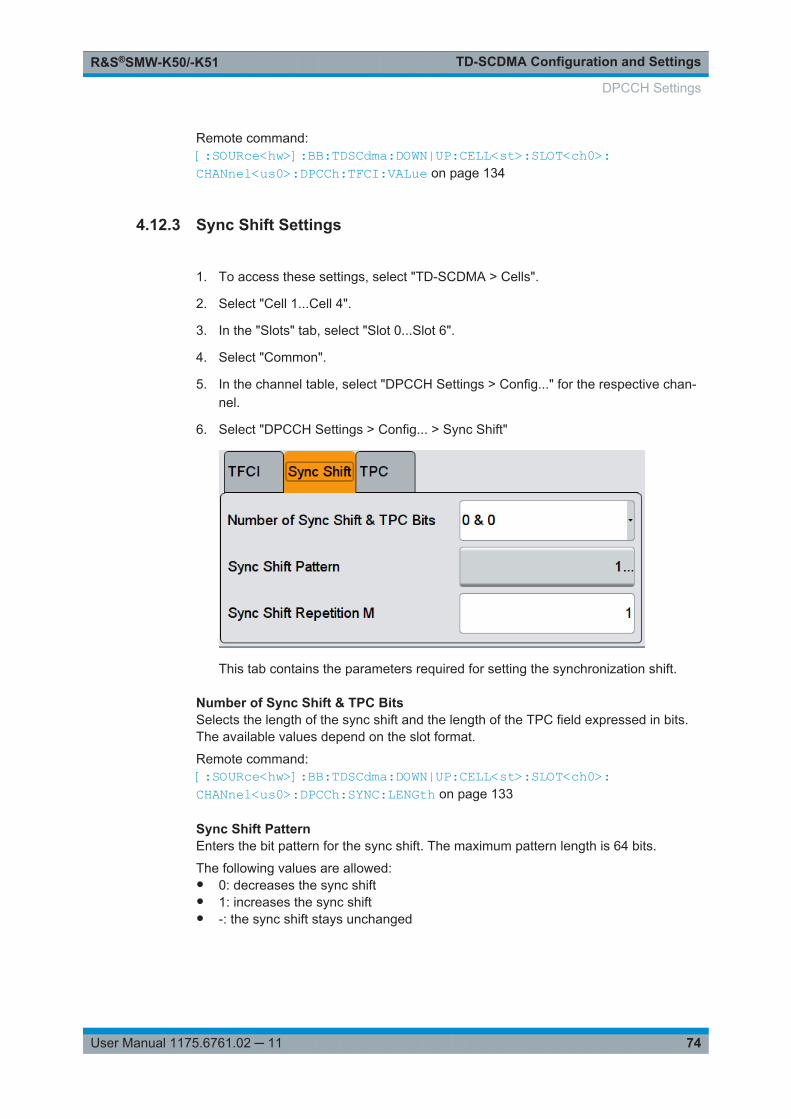
TD-SCDMA Configuration and SettingsR&S®SMW-K50/-K51
74User Manual 1175.6761.02 ─ 11
Remote command: [:SOURce<hw>]:BB:TDSCdma:DOWN|UP:CELL<st>:SLOT<ch0>:CHANnel<us0>:DPCCh:TFCI:VALue on page 134
4.12.3 Sync Shift Settings
1. To access these settings, select "TD-SCDMA > Cells".
2. Select "Cell 1...Cell 4".
3. In the "Slots" tab, select "Slot 0...Slot 6".
4. Select "Common".
5. In the channel table, select "DPCCH Settings > Config..." for the respective chan-nel.
6. Select "DPCCH Settings > Config... > Sync Shift"
This tab contains the parameters required for setting the synchronization shift.
Number of Sync Shift & TPC BitsSelects the length of the sync shift and the length of the TPC field expressed in bits.The available values depend on the slot format.
Remote command: [:SOURce<hw>]:BB:TDSCdma:DOWN|UP:CELL<st>:SLOT<ch0>:CHANnel<us0>:DPCCh:SYNC:LENGth on page 133
Sync Shift PatternEnters the bit pattern for the sync shift. The maximum pattern length is 64 bits.
The following values are allowed:● 0: decreases the sync shift● 1: increases the sync shift● -: the sync shift stays unchanged
DPCCH Settings
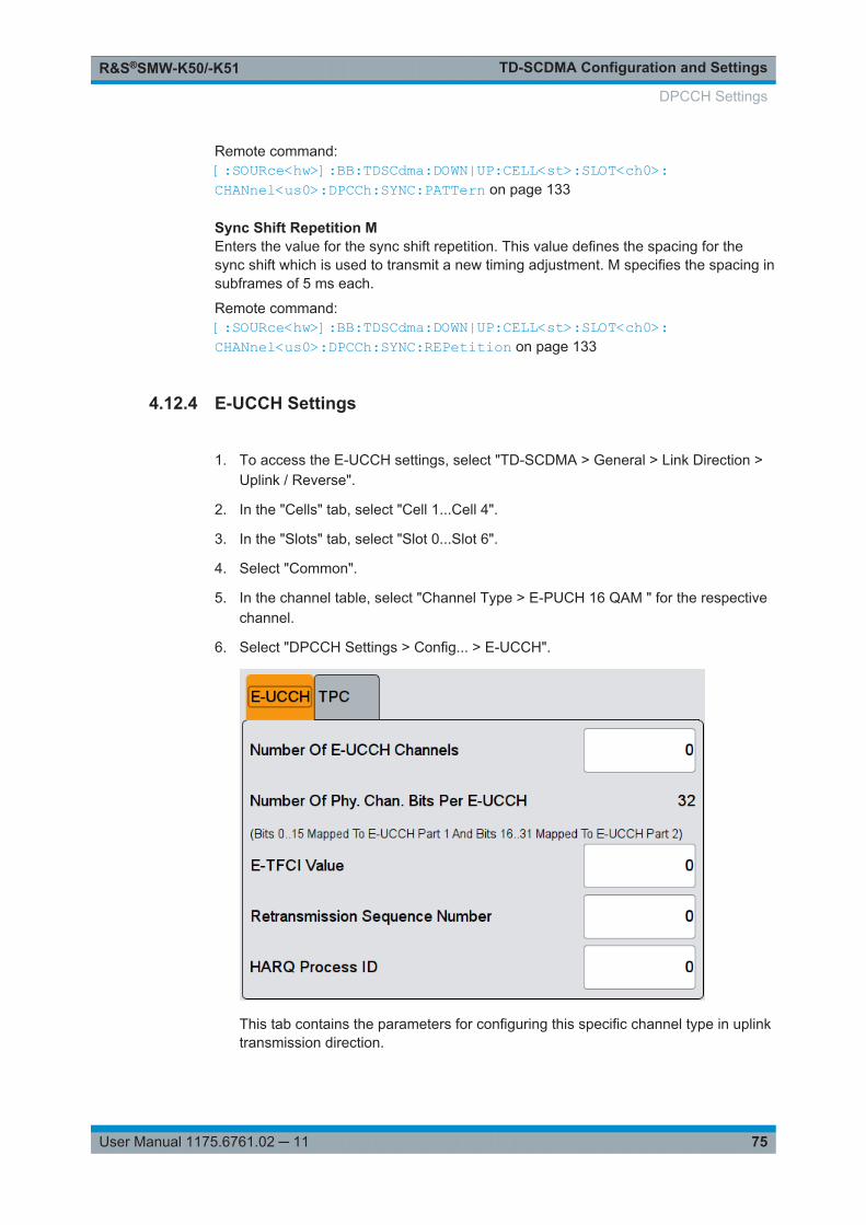
TD-SCDMA Configuration and SettingsR&S®SMW-K50/-K51
75User Manual 1175.6761.02 ─ 11
Remote command: [:SOURce<hw>]:BB:TDSCdma:DOWN|UP:CELL<st>:SLOT<ch0>:CHANnel<us0>:DPCCh:SYNC:PATTern on page 133
Sync Shift Repetition MEnters the value for the sync shift repetition. This value defines the spacing for thesync shift which is used to transmit a new timing adjustment. M specifies the spacing insubframes of 5 ms each.
Remote command: [:SOURce<hw>]:BB:TDSCdma:DOWN|UP:CELL<st>:SLOT<ch0>:CHANnel<us0>:DPCCh:SYNC:REPetition on page 133
4.12.4 E-UCCH Settings
1. To access the E-UCCH settings, select "TD-SCDMA > General > Link Direction >Uplink / Reverse".
2. In the "Cells" tab, select "Cell 1...Cell 4".
3. In the "Slots" tab, select "Slot 0...Slot 6".
4. Select "Common".
5. In the channel table, select "Channel Type > E-PUCH 16 QAM " for the respectivechannel.
6. Select "DPCCH Settings > Config... > E-UCCH".
This tab contains the parameters for configuring this specific channel type in uplinktransmission direction.
DPCCH Settings
TD-SCDMA Configuration and SettingsR&S®SMW-K50/-K51
76User Manual 1175.6761.02 ─ 11
These settings are preconfigured and disabled, if an HSUPA coding type is enabled forthe corresponding channel.
Number of E-UCCH ChannelsSets the number of the E-DCH Uplink Control Channels (E-UCCH).
Remote command: [:SOURce<hw>]:BB:TDSCdma:UP:CELL<st>:SLOT<ch0>:CHANnel<us0>:DPCCh:EUCC:CCOunt on page 130
Number of Phy. Chan. Bits per E-UCCHDisplays the number of physical channel bits per one E-UCCH.
The value is fixed to 32.
Remote command: n.a.
E-TFCI ValueEnters the value of the TFCI field.
If an HSUPA is enabled for the corresponding channel, the E-TFCI value is set to thevalue configured for the parameter Transport Block Size Index .
Remote command: [:SOURce<hw>]:BB:TDSCdma:UP:CELL<st>:SLOT<ch0>:CHANnel<us0>:DPCCh:EUCC:TFCI on page 131
Retransmission Sequence Number (E-UCCH)Sets the retransmission sequence number.
Remote command: [:SOURce<hw>]:BB:TDSCdma:UP:CELL<st>:SLOT<ch0>:CHANnel<us0>:DPCCh:EUCC:RSNumber on page 131
HARQ Process IDSets the HARQ process ID.
Remote command: [:SOURce<hw>]:BB:TDSCdma:UP:CELL<st>:SLOT<ch0>:CHANnel<us0>:DPCCh:EUCC:HPID on page 130
4.12.5 TPC Settings
The "TPC" tab contains the parameters required for configuring the TPC field.
1. To access the TPC settings, select "TD-SCDMA > Cells".
2. Select "Cell 1...Cell 4".
3. In the "Slots" tab, select "Slot 0...Slot 6".
4. Select "Common".
DPCCH Settings
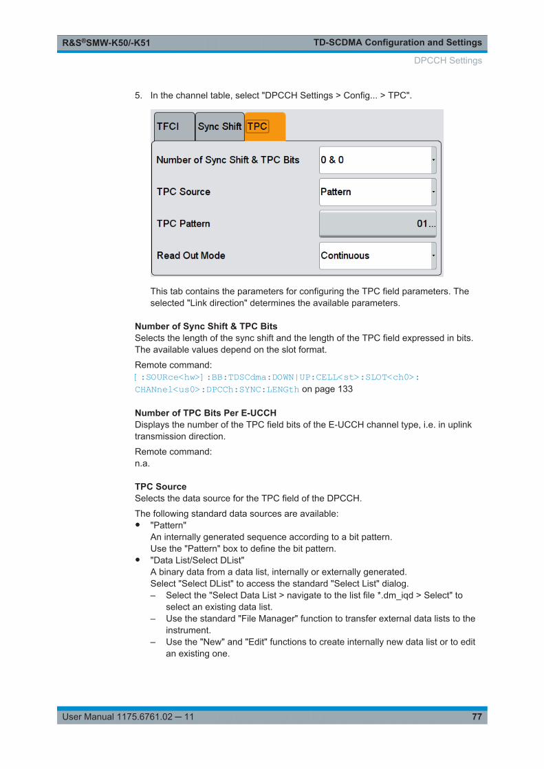
TD-SCDMA Configuration and SettingsR&S®SMW-K50/-K51
77User Manual 1175.6761.02 ─ 11
5. In the channel table, select "DPCCH Settings > Config... > TPC".
This tab contains the parameters for configuring the TPC field parameters. Theselected "Link direction" determines the available parameters.
Number of Sync Shift & TPC BitsSelects the length of the sync shift and the length of the TPC field expressed in bits.The available values depend on the slot format.
Remote command: [:SOURce<hw>]:BB:TDSCdma:DOWN|UP:CELL<st>:SLOT<ch0>:CHANnel<us0>:DPCCh:SYNC:LENGth on page 133
Number of TPC Bits Per E-UCCHDisplays the number of the TPC field bits of the E-UCCH channel type, i.e. in uplinktransmission direction.
Remote command: n.a.
TPC SourceSelects the data source for the TPC field of the DPCCH.
The following standard data sources are available:● "Pattern"
An internally generated sequence according to a bit pattern.Use the "Pattern" box to define the bit pattern.
● "Data List/Select DList"A binary data from a data list, internally or externally generated.Select "Select DList" to access the standard "Select List" dialog.– Select the "Select Data List > navigate to the list file *.dm_iqd > Select" to
select an existing data list.– Use the standard "File Manager" function to transfer external data lists to the
instrument.– Use the "New" and "Edit" functions to create internally new data list or to edit
an existing one.
DPCCH Settings
TD-SCDMA Configuration and SettingsR&S®SMW-K50/-K51
78User Manual 1175.6761.02 ─ 11
Remote command: [:SOURce<hw>]:BB:TDSCdma:DOWN|UP:CELL<st>:SLOT<ch0>:CHANnel<us0>:DPCCh:TPC:DATA on page 134[:SOURce<hw>]:BB:TDSCdma:DOWN|UP:CELL<st>:SLOT<ch0>:CHANnel<us0>:DPCCh:TPC:DATA:PATTern on page 135[:SOURce<hw>]:BB:TDSCdma:DOWN|UP:CELL<st>:SLOT<ch0>:CHANnel<us0>:DPCCh:TPC:DATA:DSELect on page 134
Read Out ModeDefines TPC data usage.
The TPC bits are used to signal the increase or reduction in transmit power to thecalled station. For all read out modes, 1 bit is taken from the data stream for the TPCfield for each slot. The bit is entered into the bitstream several times, depending on thesymbol rate. The difference between the modes lies in the usage of the TPC bits.
The different modes can be used to set a specific output power and then let the poweroscillate around this value. For example, if the power is the pattern 11111, the powercan be varied with "Single + alt. 01" and "Single + alt. 10". Thus, power measurementscan be carried out at quasi-constant power.● "Continuous:"
The TPC bits are used cyclically.● "Single + All 0"
The TPC bits are used once, and then the TPC sequence is continued with 0 bits.● "Single + All 1"
The TPC bits are used once, and then the TPC sequence is continued with 1 bit.● "Single + alt. 01"
The TPC bits are used once and then the TPC sequence is continued with 0 bitsand 1 bit alternately. Bits as appended in multiples, depending on the symbol rate,for example, 00001111.
● "Single + alt. 10"The TPC bits are used once and then the TPC sequence is continued with 1 bitand 0 bits alternately. Bits as appended in multiples, depending on by the symbolrate, for example, 11110000.
Remote command: [:SOURce<hw>]:BB:TDSCdma:DOWN|UP:CELL<st>:SLOT<ch0>:CHANnel<us0>:DPCCh:TPC:READ on page 135
4.13 Slot Mode PRACH Settings
For uplink transmission direction, the "TD-SCDMA-Cell/Slot../UL" dialog contains theparameters required for configuring the (physical random access channel) PRACH andthe UpTS (uplink pilot timeslot ).
Slot Mode PRACH Settings
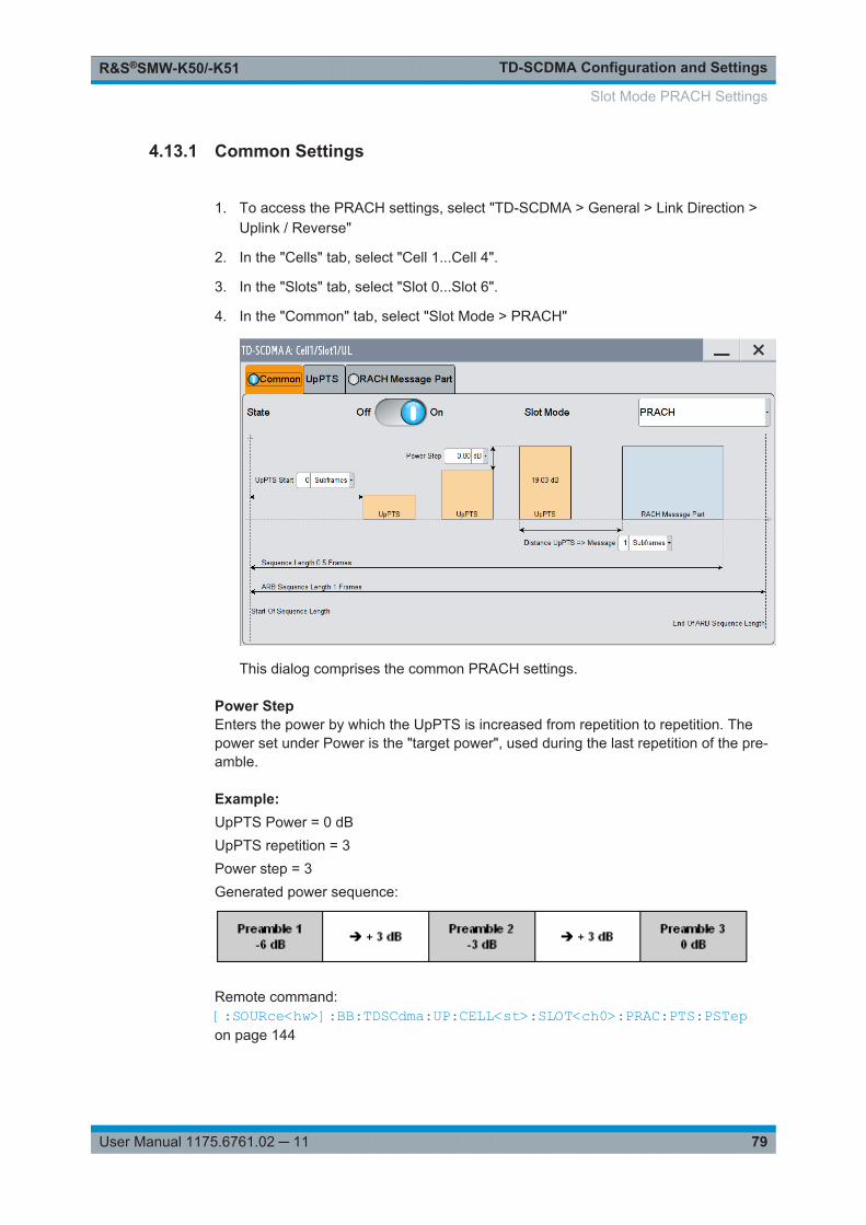
TD-SCDMA Configuration and SettingsR&S®SMW-K50/-K51
79User Manual 1175.6761.02 ─ 11
4.13.1 Common Settings
1. To access the PRACH settings, select "TD-SCDMA > General > Link Direction >Uplink / Reverse"
2. In the "Cells" tab, select "Cell 1...Cell 4".
3. In the "Slots" tab, select "Slot 0...Slot 6".
4. In the "Common" tab, select "Slot Mode > PRACH"
This dialog comprises the common PRACH settings.
Power StepEnters the power by which the UpPTS is increased from repetition to repetition. Thepower set under Power is the "target power", used during the last repetition of the pre-amble.
Example: UpPTS Power = 0 dBUpPTS repetition = 3Power step = 3Generated power sequence:
Remote command: [:SOURce<hw>]:BB:TDSCdma:UP:CELL<st>:SLOT<ch0>:PRAC:PTS:PSTepon page 144
Slot Mode PRACH Settings
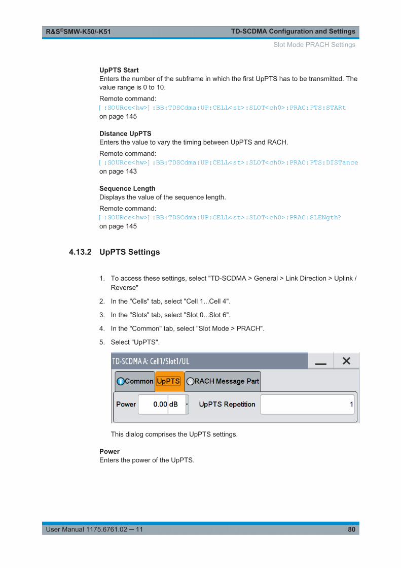
TD-SCDMA Configuration and SettingsR&S®SMW-K50/-K51
80User Manual 1175.6761.02 ─ 11
UpPTS StartEnters the number of the subframe in which the first UpPTS has to be transmitted. Thevalue range is 0 to 10.
Remote command: [:SOURce<hw>]:BB:TDSCdma:UP:CELL<st>:SLOT<ch0>:PRAC:PTS:STARton page 145
Distance UpPTSEnters the value to vary the timing between UpPTS and RACH.
Remote command: [:SOURce<hw>]:BB:TDSCdma:UP:CELL<st>:SLOT<ch0>:PRAC:PTS:DISTanceon page 143
Sequence LengthDisplays the value of the sequence length.
Remote command: [:SOURce<hw>]:BB:TDSCdma:UP:CELL<st>:SLOT<ch0>:PRAC:SLENgth?on page 145
4.13.2 UpPTS Settings
1. To access these settings, select "TD-SCDMA > General > Link Direction > Uplink /Reverse"
2. In the "Cells" tab, select "Cell 1...Cell 4".
3. In the "Slots" tab, select "Slot 0...Slot 6".
4. In the "Common" tab, select "Slot Mode > PRACH".
5. Select "UpPTS".
This dialog comprises the UpPTS settings.
PowerEnters the power of the UpPTS.
Slot Mode PRACH Settings
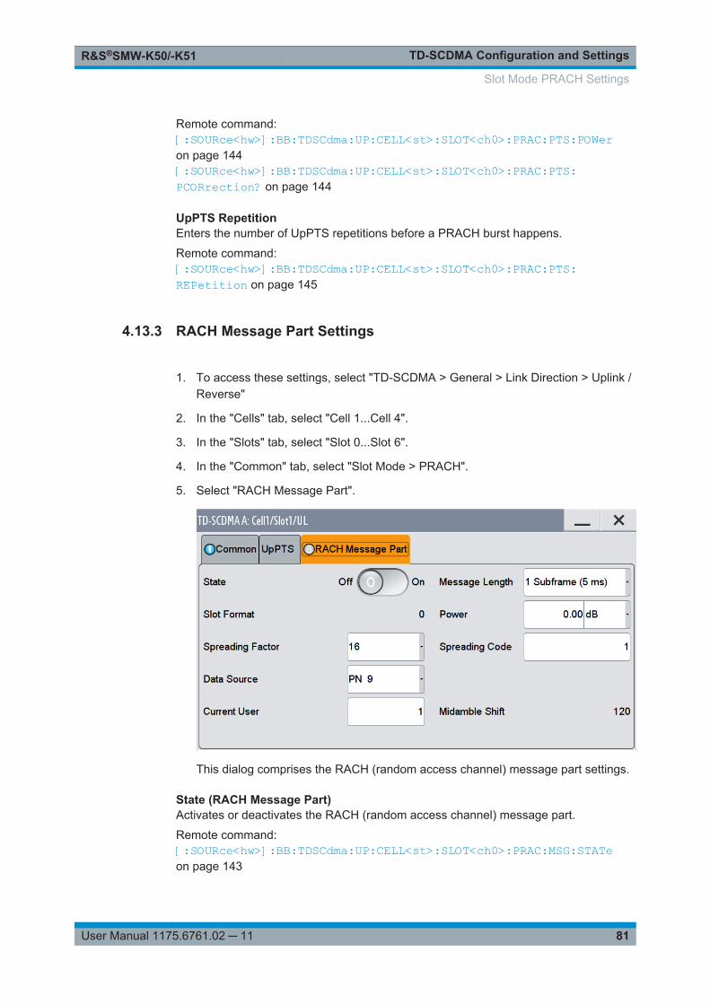
TD-SCDMA Configuration and SettingsR&S®SMW-K50/-K51
81User Manual 1175.6761.02 ─ 11
Remote command: [:SOURce<hw>]:BB:TDSCdma:UP:CELL<st>:SLOT<ch0>:PRAC:PTS:POWeron page 144[:SOURce<hw>]:BB:TDSCdma:UP:CELL<st>:SLOT<ch0>:PRAC:PTS:PCORrection? on page 144
UpPTS RepetitionEnters the number of UpPTS repetitions before a PRACH burst happens.
Remote command: [:SOURce<hw>]:BB:TDSCdma:UP:CELL<st>:SLOT<ch0>:PRAC:PTS:REPetition on page 145
4.13.3 RACH Message Part Settings
1. To access these settings, select "TD-SCDMA > General > Link Direction > Uplink /Reverse"
2. In the "Cells" tab, select "Cell 1...Cell 4".
3. In the "Slots" tab, select "Slot 0...Slot 6".
4. In the "Common" tab, select "Slot Mode > PRACH".
5. Select "RACH Message Part".
This dialog comprises the RACH (random access channel) message part settings.
State (RACH Message Part)Activates or deactivates the RACH (random access channel) message part.
Remote command: [:SOURce<hw>]:BB:TDSCdma:UP:CELL<st>:SLOT<ch0>:PRAC:MSG:STATeon page 143
Slot Mode PRACH Settings
TD-SCDMA Configuration and SettingsR&S®SMW-K50/-K51
82User Manual 1175.6761.02 ─ 11
Message LengthSelects the message length of the random access channel expressed in subframes.
Remote command: [:SOURce<hw>]:BB:TDSCdma:UP:CELL<st>:SLOT<ch0>:PRAC:MSG:LENGthon page 141
Slot Format (PRACH)Displays the slot format of the PRACH. The slot format depends on the selectedspreading factor.
Remote command: [:SOURce<hw>]:BB:TDSCdma:UP:CELL<st>:SLOT<ch0>:PRAC:MSG:SFORmat?on page 142
Power (RACH Message Part)Enters the power of the PRACH message part.
The value range is -80 dB to 0 dB.
Remote command: [:SOURce<hw>]:BB:TDSCdma:UP:CELL<st>:SLOT<ch0>:PRAC:MSG:POWeron page 142[:SOURce<hw>]:BB:TDSCdma:UP:CELL<st>:SLOT<ch0>:PRAC:MSG:PCORrection on page 141
Spreading Factor (PRACH)Selects the spreading factor for the PRACH.
Remote command: [:SOURce<hw>]:BB:TDSCdma:UP:CELL<st>:SLOT<ch0>:PRAC:MSG:SFACtoron page 142
Spreading Code (PRACH)Enters the spreading code for the PRACH. The code channel is spread with the setspreading code. The range of values of the spreading code depends on the channeltype and the spreading factor.
Remote command: [:SOURce<hw>]:BB:TDSCdma:UP:CELL<st>:SLOT<ch0>:PRAC:MSG:SCODeon page 142
Data Source (PRACH)Selects data source for the PRACH.
The following standard data sources are available:● "All 0, All 1"
An internally generated sequence containing 0 data or 1 data.● "PNxx"
An internally generated pseudo-random noise sequence.● "Pattern"
An internally generated sequence according to a bit pattern.Use the "Pattern" box to define the bit pattern.
● "Data List/Select DList"
Slot Mode PRACH Settings
TD-SCDMA Configuration and SettingsR&S®SMW-K50/-K51
83User Manual 1175.6761.02 ─ 11
A binary data from a data list, internally or externally generated.Select "Select DList" to access the standard "Select List" dialog.– Select the "Select Data List > navigate to the list file *.dm_iqd > Select" to
select an existing data list.– Use the "New" and "Edit" functions to create internally new data list or to edit
an existing one.– Use the standard "File Manager" function to transfer external data lists to the
instrument.See also:● Section "Modulation Data" in the R&S SMW user manual.● Section "File and Data Management" in the R&S SMW user manual.● Section "Data List Editor" in the R&S SMW user manual
Remote command: [:SOURce<hw>]:BB:TDSCdma:UP:CELL<st>:SLOT<ch0>:PRAC:MSG:DATAon page 139[:SOURce<hw>]:BB:TDSCdma:UP:CELL<st>:SLOT<ch0>:PRAC:MSG:DATA:DSELect on page 140[:SOURce<hw>]:BB:TDSCdma:UP:CELL<st>:SLOT<ch0>:PRAC:MSG:DATA:PATTern on page 140
Current User (PRACH)Enters the number of current users.
Remote command: [:SOURce<hw>]:BB:TDSCdma:UP:CELL<st>:SLOT<ch0>:PRAC:MSG:USERon page 143
Midamble Shift (PRACH)Displays the value for the midamble shift.
Remote command: [:SOURce<hw>]:BB:TDSCdma:UP:CELL<st>:SLOT<ch0>:PRAC:MSG:MSHift?on page 141
4.14 Filter / Clipping / ARB Settings
Access:
► Select "TD-SCDMA > General > Filter/Clipping/ARB Settings".
The dialog comprises the settings, necessary to configure the baseband filter, toenable clipping and adjust the sequence length of the arbitrary waveform compo-nent.
Filter / Clipping / ARB Settings
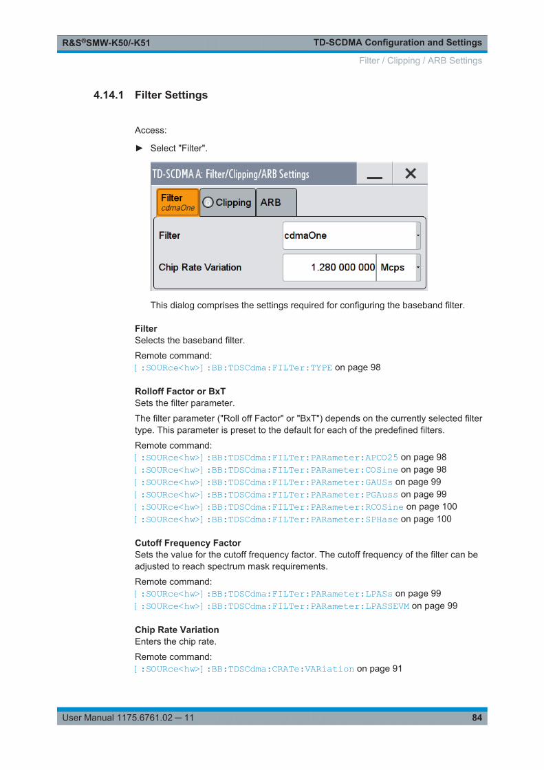
TD-SCDMA Configuration and SettingsR&S®SMW-K50/-K51
84User Manual 1175.6761.02 ─ 11
4.14.1 Filter Settings
Access:
► Select "Filter".
This dialog comprises the settings required for configuring the baseband filter.
FilterSelects the baseband filter.
Remote command: [:SOURce<hw>]:BB:TDSCdma:FILTer:TYPE on page 98
Rolloff Factor or BxTSets the filter parameter.
The filter parameter ("Roll off Factor" or "BxT") depends on the currently selected filtertype. This parameter is preset to the default for each of the predefined filters.
Remote command: [:SOURce<hw>]:BB:TDSCdma:FILTer:PARameter:APCO25 on page 98[:SOURce<hw>]:BB:TDSCdma:FILTer:PARameter:COSine on page 98[:SOURce<hw>]:BB:TDSCdma:FILTer:PARameter:GAUSs on page 99[:SOURce<hw>]:BB:TDSCdma:FILTer:PARameter:PGAuss on page 99[:SOURce<hw>]:BB:TDSCdma:FILTer:PARameter:RCOSine on page 100[:SOURce<hw>]:BB:TDSCdma:FILTer:PARameter:SPHase on page 100
Cutoff Frequency FactorSets the value for the cutoff frequency factor. The cutoff frequency of the filter can beadjusted to reach spectrum mask requirements.
Remote command: [:SOURce<hw>]:BB:TDSCdma:FILTer:PARameter:LPASs on page 99[:SOURce<hw>]:BB:TDSCdma:FILTer:PARameter:LPASSEVM on page 99
Chip Rate VariationEnters the chip rate.
Remote command: [:SOURce<hw>]:BB:TDSCdma:CRATe:VARiation on page 91
Filter / Clipping / ARB Settings
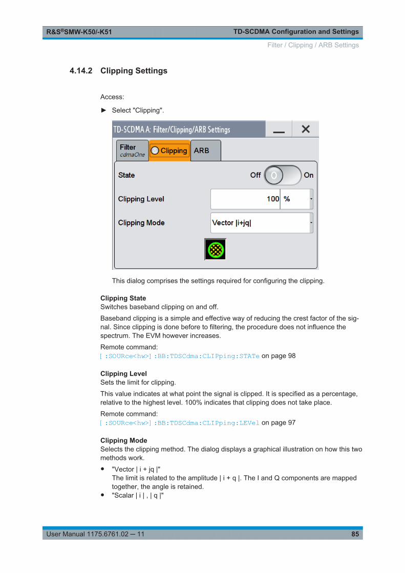
TD-SCDMA Configuration and SettingsR&S®SMW-K50/-K51
85User Manual 1175.6761.02 ─ 11
4.14.2 Clipping Settings
Access:
► Select "Clipping".
This dialog comprises the settings required for configuring the clipping.
Clipping StateSwitches baseband clipping on and off.
Baseband clipping is a simple and effective way of reducing the crest factor of the sig-nal. Since clipping is done before to filtering, the procedure does not influence thespectrum. The EVM however increases.
Remote command: [:SOURce<hw>]:BB:TDSCdma:CLIPping:STATe on page 98
Clipping LevelSets the limit for clipping.
This value indicates at what point the signal is clipped. It is specified as a percentage,relative to the highest level. 100% indicates that clipping does not take place.
Remote command: [:SOURce<hw>]:BB:TDSCdma:CLIPping:LEVel on page 97
Clipping ModeSelects the clipping method. The dialog displays a graphical illustration on how this twomethods work.● "Vector | i + jq |"
The limit is related to the amplitude | i + q |. The I and Q components are mappedtogether, the angle is retained.
● "Scalar | i | , | q |"
Filter / Clipping / ARB Settings
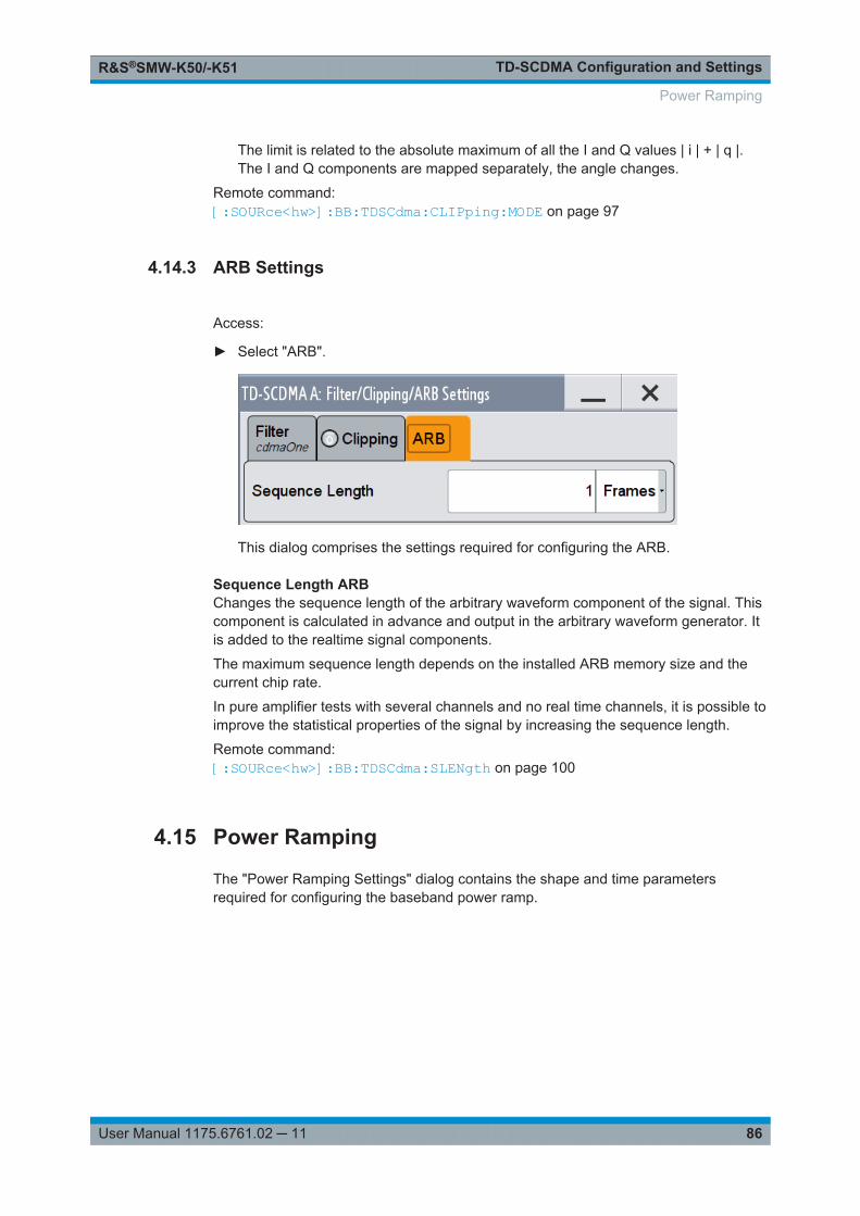
TD-SCDMA Configuration and SettingsR&S®SMW-K50/-K51
86User Manual 1175.6761.02 ─ 11
The limit is related to the absolute maximum of all the I and Q values | i | + | q |.The I and Q components are mapped separately, the angle changes.
Remote command: [:SOURce<hw>]:BB:TDSCdma:CLIPping:MODE on page 97
4.14.3 ARB Settings
Access:
► Select "ARB".
This dialog comprises the settings required for configuring the ARB.
Sequence Length ARBChanges the sequence length of the arbitrary waveform component of the signal. Thiscomponent is calculated in advance and output in the arbitrary waveform generator. Itis added to the realtime signal components.
The maximum sequence length depends on the installed ARB memory size and thecurrent chip rate.
In pure amplifier tests with several channels and no real time channels, it is possible toimprove the statistical properties of the signal by increasing the sequence length.
Remote command: [:SOURce<hw>]:BB:TDSCdma:SLENgth on page 100
4.15 Power Ramping
The "Power Ramping Settings" dialog contains the shape and time parametersrequired for configuring the baseband power ramp.
Power Ramping
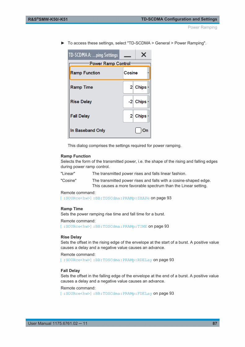
TD-SCDMA Configuration and SettingsR&S®SMW-K50/-K51
87User Manual 1175.6761.02 ─ 11
► To access these settings, select "TD-SCDMA > General > Power Ramping".
This dialog comprises the settings required for power ramping.
Ramp FunctionSelects the form of the transmitted power, i.e. the shape of the rising and falling edgesduring power ramp control.
"Linear" The transmitted power rises and falls linear fashion.
"Cosine" The transmitted power rises and falls with a cosine-shaped edge.This causes a more favorable spectrum than the Linear setting.
Remote command: [:SOURce<hw>]:BB:TDSCdma:PRAMp:SHAPe on page 93
Ramp TimeSets the power ramping rise time and fall time for a burst.
Remote command: [:SOURce<hw>]:BB:TDSCdma:PRAMp:TIME on page 93
Rise DelaySets the offset in the rising edge of the envelope at the start of a burst. A positive valuecauses a delay and a negative value causes an advance.
Remote command: [:SOURce<hw>]:BB:TDSCdma:PRAMp:RDELay on page 93
Fall DelaySets the offset in the falling edge of the envelope at the end of a burst. A positive valuecauses a delay and a negative value causes an advance.
Remote command: [:SOURce<hw>]:BB:TDSCdma:PRAMp:FDELay on page 93
Power Ramping
TD-SCDMA Configuration and SettingsR&S®SMW-K50/-K51
88User Manual 1175.6761.02 ─ 11
In Baseband OnlyActivates or deactivates power ramping for the baseband signals.
Remote command: [:SOURce<hw>]:BB:TDSCdma:PRAMp:BBONly on page 93
Power Ramping
Remote-Control CommandsR&S®SMW-K50/-K51
89User Manual 1175.6761.02 ─ 11
5 Remote-Control CommandsThe following commands are required to perform signal generation with the TD-SCDMA options in a remote environment. We assume that the R&S SMW has alreadybeen set up for remote operation in a network as described in the R&S SMW docu-mentation. A knowledge about the remote control operation and the SCPI commandsyntax are assumed.
Conventions used in SCPI command descriptionsFor a description of the conventions used in the remote command descriptions, seesection "Remote Control Commands" in the R&S SMW user manual.
Common suffixes
The following common suffixes are used in remote commands:
Suffix Value range Description
ENTity<ch> 1 to 4 entity in a multiple entity configuration with separate base-band sources
ENTity3|4 require option R&S SMW-K76
SOURce<hw> [1]|4 available baseband signals
only SOURce1 possible, if the keyword ENTity is used
OUTPut<ch> 1 to 3 available markers
CELL<st> [1]|2|3|4 Cell
DTCH<ch> 1 to 7
SLOT<ch0> [0] to 6 Slot number
CHANnel<us0> [0] to 21 Channel number
Using SCPI command aliases for advanced mode with multiple entitiesYou can address multiple entities configurations by using the SCPI commands startingwith the keyword SOURce or the alias commands starting with the keyword ENTity.
Note that the meaning of the keyword SOURce<hw> changes in the second case.
For details, see section "SCPI Command Aliases for Advanced Mode with MultipleEntities" in the R&S SMW user manual.
The following commands specific to the TD-SCDMA are described here:
● General Commands................................................................................................90● Filter/Clipping/ARB Settings....................................................................................97● Trigger Settings.....................................................................................................101● Marker Settings.....................................................................................................105● Clock Settings....................................................................................................... 107● Predefined Settings...............................................................................................107● Cell Settings..........................................................................................................109
Remote-Control CommandsR&S®SMW-K50/-K51
90User Manual 1175.6761.02 ─ 11
● Enhanced Channels of Cell 1................................................................................113● Channel Settings...................................................................................................129● HSDPA/HSUPA Settings...................................................................................... 146
5.1 General Commands
[:SOURce<hw>]:BB:TDSCdma:COPY:SOURce..................................................................90[:SOURce<hw>]:BB:TDSCdma:COPY:DESTination............................................................ 90[:SOURce<hw>]:BB:TDSCdma:COPY:EXECute................................................................. 91[:SOURce<hw>]:BB:TDSCdma:CRATe?............................................................................ 91[:SOURce<hw>]:BB:TDSCdma:CRATe:VARiation...............................................................91[:SOURce<hw>]:BB:TDSCdma:LINK..................................................................................92[:SOURce<hw>]:BB:TDSCdma:POWer:ADJust...................................................................92[:SOURce<hw>]:BB:TDSCdma:POWer[:TOTal]?.................................................................92[:SOURce<hw>]:BB:TDSCdma:PRAMp:BBONly................................................................. 93[:SOURce<hw>]:BB:TDSCdma:PRAMp:FDELay.................................................................93[:SOURce<hw>]:BB:TDSCdma:PRAMp:RDELay.................................................................93[:SOURce<hw>]:BB:TDSCdma:PRAMp:SHAPe.................................................................. 93[:SOURce<hw>]:BB:TDSCdma:PRAMp:TIME.....................................................................93[:SOURce<hw>]:BB:TDSCdma:PRESet............................................................................. 94[:SOURce<hw>]:BB:TDSCdma:RESet............................................................................... 94[:SOURce<hw>]:BB:TDSCdma:SETTing:CATalog?.............................................................94[:SOURce<hw>]:BB:TDSCdma:SETTing:LOAD.................................................................. 95[:SOURce<hw>]:BB:TDSCdma:SETTing:STORe................................................................ 95[:SOURce<hw>]:BB:TDSCdma:SETTing:TMODel............................................................... 95[:SOURce<hw>]:BB:TDSCdma:SETTing:TMODel:CATalog?................................................95[:SOURce<hw>]:BB:TDSCdma:STATe...............................................................................96[:SOURce<hw>]:BB:TDSCdma:VERSion?..........................................................................96[:SOURce<hw>]:BB:TDSCdma:WAVeform:CREate.............................................................96
[:SOURce<hw>]:BB:TDSCdma:COPY:SOURce <Source>
Selects the cell whose settings are to be copied.
Parameters:<Source> 1 | 2 | 3 | 4
Range: 1 to 4*RST: 1 (Cell1)
Example: See [:SOURce<hw>]:BB:TDSCdma:COPY:DESTinationon page 90
Manual operation: See "Copy Cell..." on page 29
[:SOURce<hw>]:BB:TDSCdma:COPY:DESTination <Destination>
Selects the cell whose settings are to be overwritten.
General Commands
Remote-Control CommandsR&S®SMW-K50/-K51
91User Manual 1175.6761.02 ─ 11
Parameters:<Destination> 1 | 2 | 3 | 4
Range: 1 to 4*RST: 2 (Cell2)
Example: BB:TDSC:LINK DOWNBB:TDSC:COPY:SOUR 1BB:TDSC:COPY:DEST 4BB:TDSC:COPY:EXEC
Manual operation: See "Copy Cell..." on page 29
[:SOURce<hw>]:BB:TDSCdma:COPY:EXECute
Starts the copy process. The dataset of the selected source cell is copied to the desti-nation cell.
Example: See [:SOURce<hw>]:BB:TDSCdma:COPY:DESTinationon page 90
Usage: Event
Manual operation: See "Copy Cell..." on page 29
[:SOURce<hw>]:BB:TDSCdma:CRATe?
Queries the system chip rate.
The output chip rate which determines the rate of the spread symbols as is used forsignal output can be set with the command SOUR:BB:TDSC:CRAT:VAR.
Return values: <CRate> R1M28
*RST: R1M28
Example: BB:TDSC:CRAT?Response: R1M2The system chip rate is 1.2288 Mcps.
Usage: Query only
Manual operation: See " Chip Rate " on page 19
[:SOURce<hw>]:BB:TDSCdma:CRATe:VARiation <Variation>
Sets the output chip rate.
The output chip rate changes the output clock and the modulation bandwidth, as wellas the synchronization signals that are output. It does not affect the calculated chipsequence.
General Commands
Remote-Control CommandsR&S®SMW-K50/-K51
92User Manual 1175.6761.02 ─ 11
Parameters:<Variation> float
Range: 400 to 5E6Increment: 0.001*RST: 1280000Default unit: Hz (c/s)
Example: BB:TDSC:CRAT:VAR 4086001sets the chip rate to 4.08 Mcps.
Manual operation: See "Chip Rate Variation" on page 84
[:SOURce<hw>]:BB:TDSCdma:LINK <Link>
Defines the transmission direction.
Parameters:<Link> FORWard | DOWN | REVerse | UP
*RST: DOWN
Example: BB:TDSC:LINK DOWNManual operation: See " Link Direction " on page 19
[:SOURce<hw>]:BB:TDSCdma:POWer:ADJust
The command sets the power of the active channels in such a way that the total powerof the active channels is 0 dB. This will not change the power ratio among the individ-ual channels.
Example: BB:TDSC:POW:ADJthe total power of the active channels is set to 0 dB, the powerratio among the individual channels is unchanged.
Usage: Event
Manual operation: See "Adjust Total Power to 0dB" on page 30
[:SOURce<hw>]:BB:TDSCdma:POWer[:TOTal]?
Queries the total power of the active channels. After "Power Adjust", this power corre-sponds to 0 dB.
Return values: <Total> float
Increment: 0.01
Example: BB:TDSC:POW:TOT?queries the total power of the active channels.Response: -22.5the total power is -22.5 dB.
Usage: Query only
General Commands
Remote-Control CommandsR&S®SMW-K50/-K51
93User Manual 1175.6761.02 ─ 11
Manual operation: See "Total Power" on page 30
[:SOURce<hw>]:BB:TDSCdma:PRAMp:BBONly <BbOnly>
Activates or deactivates power ramping for the baseband signals.
Parameters:<BbOnly> 0 | 1 | OFF | ON
*RST: 0
Example: BB:TDSC:PRAM:BBON ONManual operation: See " In Baseband Only " on page 88
[:SOURce<hw>]:BB:TDSCdma:PRAMp:FDELay <FDelay>[:SOURce<hw>]:BB:TDSCdma:PRAMp:RDELay <RDelay>
Sets the offset in the falling edge of the envelope at the end of a burst. A positive valuedelays the ramp and a negative value causes an advance.
Parameters:<RDelay> integer
Range: -4 to 4*RST: 2 (FDELay) / -2 (RDELay)
Example: BB:TDSC:PRAM:RDEL 8.0Sets the offset in the rising edge of the envelope to 8.0 chips.
Manual operation: See " Rise Delay " on page 87
[:SOURce<hw>]:BB:TDSCdma:PRAMp:SHAPe <Shape>
Selects the form of the transmitted power, i.e. the shape of the rising and falling edgesduring power ramp control.
Parameters:<Shape> LINear | COSine
*RST: COSine
Example: BB:TDSC:PRAM:SHAP LINSets a linear shape.
Manual operation: See " Ramp Function " on page 87
[:SOURce<hw>]:BB:TDSCdma:PRAMp:TIME <Time>
Sets the power ramping rise time and fall time for a burst.
Parameters:<Time> integer
Range: 0 to 4*RST: 2
General Commands
Remote-Control CommandsR&S®SMW-K50/-K51
94User Manual 1175.6761.02 ─ 11
Example: BB:TDSC:PRAM:TIME 2.0Manual operation: See " Ramp Time " on page 87
[:SOURce<hw>]:BB:TDSCdma:PRESet
Sets the parameters of the digital standard to their default values (*RST values speci-fied for the commands).
Not affected is the state set with the command SOURce<hw>:BB:TDSCdma:STATe.
Example: SOURce1:BB:TDSCdma:PRESetUsage: Event
Manual operation: See "Set to Default" on page 18
[:SOURce<hw>]:BB:TDSCdma:RESet
Resets all cells to the predefined settings. The reset applies to the selected link direc-tion.
An overview is provided by table in Set to Default.
Example: BB:TDSC:RESresets all the cells to the predefined settings.
Usage: Event
Manual operation: See "Reset All Cells" on page 28
[:SOURce<hw>]:BB:TDSCdma:SETTing:CATalog?
Queries the files with settings in the default directory. Listed are files with the file exten-sion *.tdscdma.
For general information on file handling in the default and in a specific directory, seesection "MMEMory Subsystem" in the R&S SMW user manual.
Return values: <Catalog> <filename1>,<filename2>,...
Returns a string of filenames separated by commas.
Example: MMEM:CDIR '/var/user/tdscdma'SOURce1:BB:TDSCdma:SETTing:CATalog?// Response: "up", "down"SOURce1:BB:TDSCdma:SETTing:LOAD "up"SOURce1:BB:TDSCdma:SETTing:STOR 'tdscdma_1'
Usage: Query only
Manual operation: See "Save/Recall" on page 19
General Commands
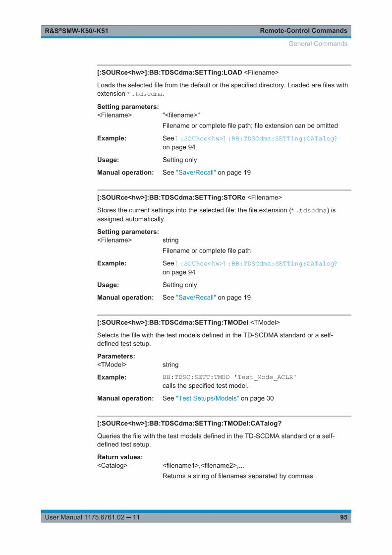
Remote-Control CommandsR&S®SMW-K50/-K51
95User Manual 1175.6761.02 ─ 11
[:SOURce<hw>]:BB:TDSCdma:SETTing:LOAD <Filename>
Loads the selected file from the default or the specified directory. Loaded are files withextension *.tdscdma.
Setting parameters: <Filename> "<filename>"
Filename or complete file path; file extension can be omitted
Example: See [:SOURce<hw>]:BB:TDSCdma:SETTing:CATalog?on page 94
Usage: Setting only
Manual operation: See "Save/Recall" on page 19
[:SOURce<hw>]:BB:TDSCdma:SETTing:STORe <Filename>
Stores the current settings into the selected file; the file extension (*.tdscdma) isassigned automatically.
Setting parameters: <Filename> string
Filename or complete file path
Example: See [:SOURce<hw>]:BB:TDSCdma:SETTing:CATalog?on page 94
Usage: Setting only
Manual operation: See "Save/Recall" on page 19
[:SOURce<hw>]:BB:TDSCdma:SETTing:TMODel <TModel>
Selects the file with the test models defined in the TD-SCDMA standard or a self-defined test setup.
Parameters:<TModel> string
Example: BB:TDSC:SETT:TMOD 'Test_Mode_ACLR'calls the specified test model.
Manual operation: See "Test Setups/Models" on page 30
[:SOURce<hw>]:BB:TDSCdma:SETTing:TMODel:CATalog?
Queries the file with the test models defined in the TD-SCDMA standard or a self-defined test setup.
Return values: <Catalog> <filename1>,<filename2>,...
Returns a string of filenames separated by commas.
General Commands
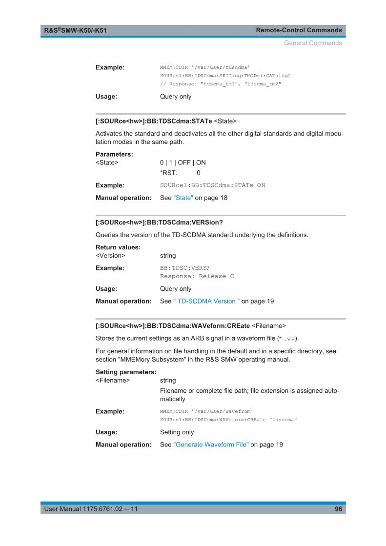
Remote-Control CommandsR&S®SMW-K50/-K51
96User Manual 1175.6761.02 ─ 11
Example: MMEM:CDIR '/var/user/tdscdma'SOURce1:BB:TDSCdma:SETTing:TMODel:CATalog?// Response: "tdscma_tm1", "tdscma_tm2"
Usage: Query only
[:SOURce<hw>]:BB:TDSCdma:STATe <State>
Activates the standard and deactivates all the other digital standards and digital modu-lation modes in the same path.
Parameters:<State> 0 | 1 | OFF | ON
*RST: 0
Example: SOURce1:BB:TDSCdma:STATe ONManual operation: See "State" on page 18
[:SOURce<hw>]:BB:TDSCdma:VERSion?
Queries the version of the TD-SCDMA standard underlying the definitions.
Return values: <Version> string
Example: BB:TDSC:VERS?Response: Release C
Usage: Query only
Manual operation: See " TD-SCDMA Version " on page 19
[:SOURce<hw>]:BB:TDSCdma:WAVeform:CREate <Filename>
Stores the current settings as an ARB signal in a waveform file (*.wv).
For general information on file handling in the default and in a specific directory, seesection "MMEMory Subsystem" in the R&S SMW operating manual.
Setting parameters: <Filename> string
Filename or complete file path; file extension is assigned auto-matically
Example: MMEM:CDIR '/var/user/wavefrom'SOURce1:BB:TDSCdma:WAVeform:CREate "tdscdma"
Usage: Setting only
Manual operation: See "Generate Waveform File" on page 19
General Commands
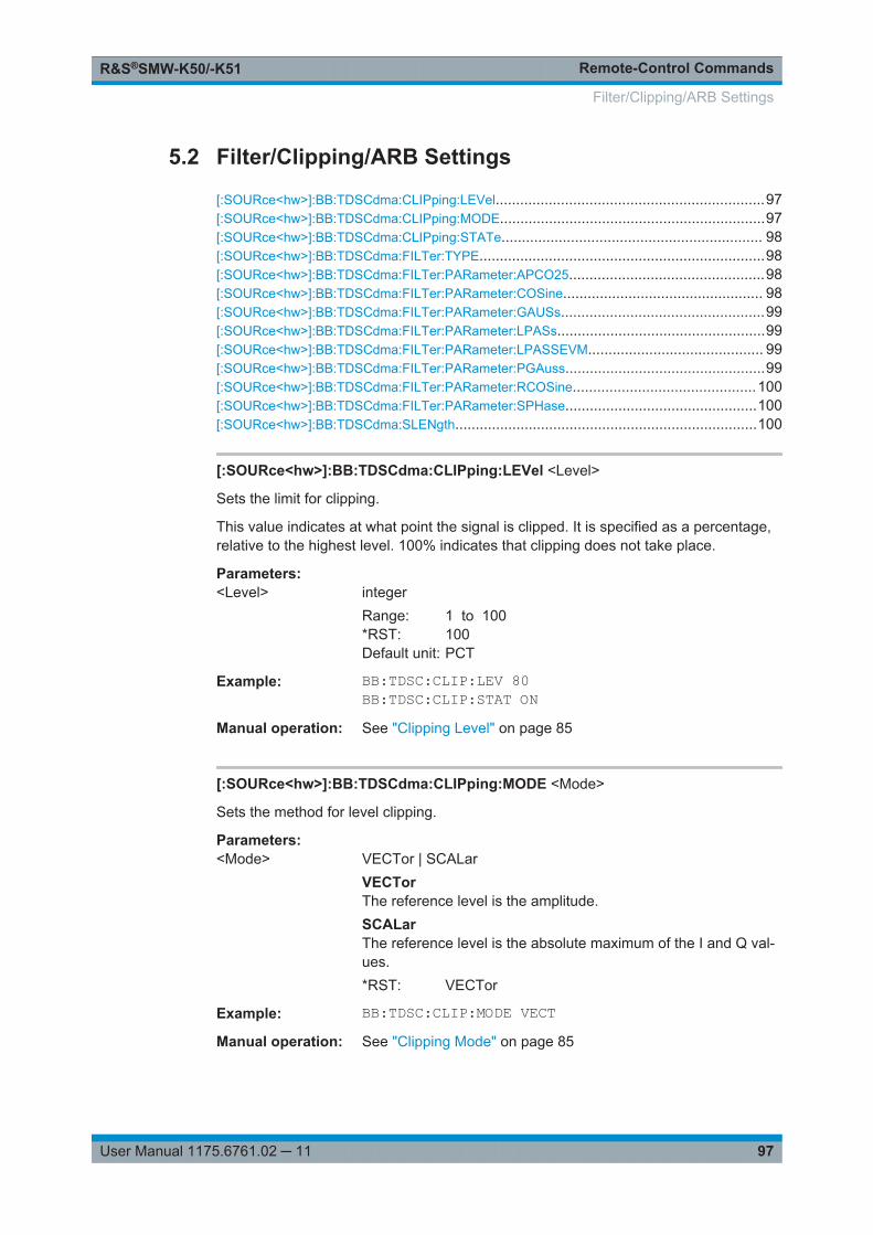
Remote-Control CommandsR&S®SMW-K50/-K51
97User Manual 1175.6761.02 ─ 11
5.2 Filter/Clipping/ARB Settings
[:SOURce<hw>]:BB:TDSCdma:CLIPping:LEVel..................................................................97[:SOURce<hw>]:BB:TDSCdma:CLIPping:MODE.................................................................97[:SOURce<hw>]:BB:TDSCdma:CLIPping:STATe................................................................ 98[:SOURce<hw>]:BB:TDSCdma:FILTer:TYPE......................................................................98[:SOURce<hw>]:BB:TDSCdma:FILTer:PARameter:APCO25................................................98[:SOURce<hw>]:BB:TDSCdma:FILTer:PARameter:COSine................................................. 98[:SOURce<hw>]:BB:TDSCdma:FILTer:PARameter:GAUSs..................................................99[:SOURce<hw>]:BB:TDSCdma:FILTer:PARameter:LPASs...................................................99[:SOURce<hw>]:BB:TDSCdma:FILTer:PARameter:LPASSEVM........................................... 99[:SOURce<hw>]:BB:TDSCdma:FILTer:PARameter:PGAuss.................................................99[:SOURce<hw>]:BB:TDSCdma:FILTer:PARameter:RCOSine.............................................100[:SOURce<hw>]:BB:TDSCdma:FILTer:PARameter:SPHase...............................................100[:SOURce<hw>]:BB:TDSCdma:SLENgth..........................................................................100
[:SOURce<hw>]:BB:TDSCdma:CLIPping:LEVel <Level>
Sets the limit for clipping.
This value indicates at what point the signal is clipped. It is specified as a percentage,relative to the highest level. 100% indicates that clipping does not take place.
Parameters:<Level> integer
Range: 1 to 100*RST: 100Default unit: PCT
Example: BB:TDSC:CLIP:LEV 80BB:TDSC:CLIP:STAT ON
Manual operation: See "Clipping Level" on page 85
[:SOURce<hw>]:BB:TDSCdma:CLIPping:MODE <Mode>
Sets the method for level clipping.
Parameters:<Mode> VECTor | SCALar
VECTorThe reference level is the amplitude.SCALarThe reference level is the absolute maximum of the I and Q val-ues.*RST: VECTor
Example: BB:TDSC:CLIP:MODE VECTManual operation: See "Clipping Mode" on page 85
Filter/Clipping/ARB Settings
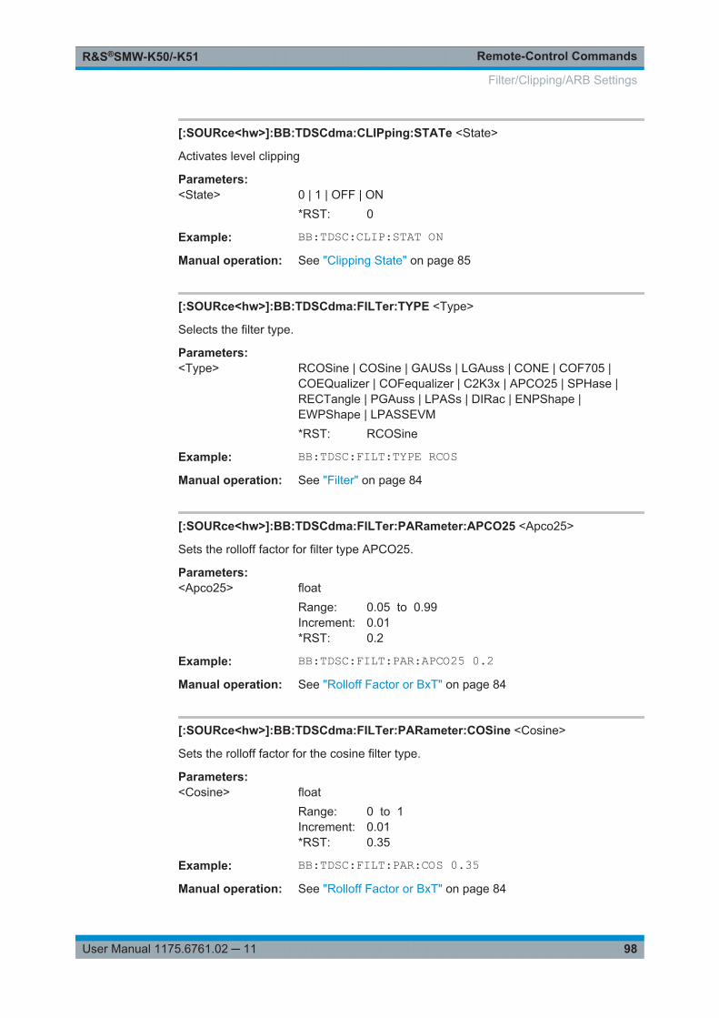
Remote-Control CommandsR&S®SMW-K50/-K51
98User Manual 1175.6761.02 ─ 11
[:SOURce<hw>]:BB:TDSCdma:CLIPping:STATe <State>
Activates level clipping
Parameters:<State> 0 | 1 | OFF | ON
*RST: 0
Example: BB:TDSC:CLIP:STAT ONManual operation: See "Clipping State" on page 85
[:SOURce<hw>]:BB:TDSCdma:FILTer:TYPE <Type>
Selects the filter type.
Parameters:<Type> RCOSine | COSine | GAUSs | LGAuss | CONE | COF705 |
COEQualizer | COFequalizer | C2K3x | APCO25 | SPHase |RECTangle | PGAuss | LPASs | DIRac | ENPShape |EWPShape | LPASSEVM*RST: RCOSine
Example: BB:TDSC:FILT:TYPE RCOSManual operation: See "Filter" on page 84
[:SOURce<hw>]:BB:TDSCdma:FILTer:PARameter:APCO25 <Apco25>
Sets the rolloff factor for filter type APCO25.
Parameters:<Apco25> float
Range: 0.05 to 0.99Increment: 0.01*RST: 0.2
Example: BB:TDSC:FILT:PAR:APCO25 0.2Manual operation: See "Rolloff Factor or BxT" on page 84
[:SOURce<hw>]:BB:TDSCdma:FILTer:PARameter:COSine <Cosine>
Sets the rolloff factor for the cosine filter type.
Parameters:<Cosine> float
Range: 0 to 1Increment: 0.01*RST: 0.35
Example: BB:TDSC:FILT:PAR:COS 0.35Manual operation: See "Rolloff Factor or BxT" on page 84
Filter/Clipping/ARB Settings
Remote-Control CommandsR&S®SMW-K50/-K51
99User Manual 1175.6761.02 ─ 11
[:SOURce<hw>]:BB:TDSCdma:FILTer:PARameter:GAUSs <Gauss>
Sets the BxT for the gauss filter type.
Parameters:<Gauss> float
Range: 0.15 to 2.5Increment: 0.01*RST: 0.5
Example: BB:TDSC:FILT:PAR:GAUS 0.5Manual operation: See "Rolloff Factor or BxT" on page 84
[:SOURce<hw>]:BB:TDSCdma:FILTer:PARameter:LPASs <LPass>
Sets the cutoff frequency factor for the Lowpass (ACP opt) filter type.
Parameters:<LPass> float
Range: 0.05 to 2Increment: 0.01*RST: 0.5
Example: BB:TDSC:FILT:PAR:LPAS 0.5Manual operation: See "Cutoff Frequency Factor" on page 84
[:SOURce<hw>]:BB:TDSCdma:FILTer:PARameter:LPASSEVM <LPassEvm>
Sets the cutoff frequency factor for the Lowpass (EVM opt) filter type.
Parameters:<LPassEvm> float
Range: 0.05 to 2Increment: 0.01*RST: 0.5
Example: BB:TDSC:FILT:PAR:LPASSEVM 0.5Manual operation: See "Cutoff Frequency Factor" on page 84
[:SOURce<hw>]:BB:TDSCdma:FILTer:PARameter:PGAuss <PGauss>
Sets the BxT for the pure gauss filter type.
Parameters:<PGauss> float
Range: 0.15 to 2.5Increment: 0.01*RST: 0.5
Example: BB:TDSC:FILT:PAR:GAUS 0.5
Filter/Clipping/ARB Settings

Remote-Control CommandsR&S®SMW-K50/-K51
100User Manual 1175.6761.02 ─ 11
Manual operation: See "Rolloff Factor or BxT" on page 84
[:SOURce<hw>]:BB:TDSCdma:FILTer:PARameter:RCOSine <RCosine>
Sets the rolloff factor for the root cosine filter type.
Parameters:<RCosine> float
Range: 0 to 1Increment: 0.01*RST: 0.22
Example: BB:TDSC:FILT:PAR:RCOS 0.22Manual operation: See "Rolloff Factor or BxT" on page 84
[:SOURce<hw>]:BB:TDSCdma:FILTer:PARameter:SPHase <SPhase>
Sets the BxT for the split phase filter type.
Parameters:<SPhase> float
Range: 0.15 to 2.5Increment: 0.01*RST: 2
Example: BB:TDSC:FILT:PAR:SPH 0.5Manual operation: See "Rolloff Factor or BxT" on page 84
[:SOURce<hw>]:BB:TDSCdma:SLENgth <SLength>
Sets the sequence length of the arbitrary waveform component of the TD-SCDMA sig-nal in the number of frames. This component is calculated in advance and output in thearbitrary waveform generator. It is added to the realtime signal components.
Parameters:<SLength> integer
Range: 1 to 5000*RST: 1
Example: BB:TDSC:SLEN 10Manual operation: See "Sequence Length ARB" on page 86
Filter/Clipping/ARB Settings
Remote-Control CommandsR&S®SMW-K50/-K51
101User Manual 1175.6761.02 ─ 11
5.3 Trigger Settings
Example: Trigger configurationSOURce1:BB:TDSCdma:TRIGger:SOURce INTernalSOURce1:BB:TDSCdma:TRIGger:SEQuence ARETriggerSOURce1:BB:TDSCdma:STAT ONSOURce1:BB:TDSCdma:TRIGger:EXECuteSOURce1:BB:TDSCdma:TRIGger:ARM:EXECuteSOURce1:BB:TDSCdma:TRIGger:RMODe?// stoppedSOURce1:BB:TDSCdma:TRIGger:EXECuteSOURce1:BB:TDSCdma:TRIGger:RMODe?// run
// SOURce1:BB:TDSCdma:TRIGger:SEQuence SING// SOURce1:BB:TDSCdma:TRIGger:SLUNit SEQuence// SOURce1:BB:TDSCdma:TRIGger:SLENgth 2
// SOURce1:BB:TDSCdma:TRIGger:SEQuence AAUT// SOURce1:BB:TDSCdma:TRIGger:SOURce EGT1// SOURce1:BB:TDSCdma:TRIGger:EXTernal:SYNChronize:OUTPut 1// SOURce1:BB:TDSCdma:TRIGger:EXTernal:INHibit 100// SOURce1:BB:TDSCdma:TRIGger:EXTernal:DELay 10
[:SOURce<hw>]:BB:TDSCdma:TRIGger:ARM:EXECute....................................................101[:SOURce<hw>]:BB:TDSCdma:TRIGger:EXECute............................................................ 101[:SOURce<hw>]:BB:TDSCdma:TRIGger:EXTernal:SYNChronize:OUTPut...........................102[:SOURce<hw>]:BB:TDSCdma:TRIGger:OBASeband:DELay.............................................102[:SOURce<hw>]:BB:TDSCdma:TRIGger:OBASeband:INHibit.............................................102[:SOURce<hw>]:BB:TDSCdma:TRIGger:RMODe?............................................................102[:SOURce<hw>]:BB:TDSCdma:TRIGger:SLENgth............................................................ 103[:SOURce<hw>]:BB:TDSCdma:TRIGger:SLUNit............................................................... 103[:SOURce<hw>]:BB:TDSCdma:TRIGger:SOURce.............................................................103[:SOURce<hw>]:BB:TDSCdma:TRIGger[:EXTernal]:DELay............................................... 104[:SOURce<hw>]:BB:TDSCdma:TRIGger[:EXTernal]:INHibit............................................... 104[:SOURce<hw>]:BB:TDSCdma[:TRIGger]:SEQuence........................................................104
[:SOURce<hw>]:BB:TDSCdma:TRIGger:ARM:EXECute
Stops signal generation; a subsequent trigger event restarts signal generation.
Example: See Example "Trigger configuration" on page 101
Usage: Event
Manual operation: See "Arm" on page 22
[:SOURce<hw>]:BB:TDSCdma:TRIGger:EXECute
Executes a trigger.
Trigger Settings
Remote-Control CommandsR&S®SMW-K50/-K51
102User Manual 1175.6761.02 ─ 11
Example: See Example "Trigger configuration" on page 101
Usage: Event
Manual operation: See "Execute Trigger" on page 22
[:SOURce<hw>]:BB:TDSCdma:TRIGger:EXTernal:SYNChronize:OUTPut<Output>
Enables signal output synchronous to the trigger event.
Parameters:<Output> 0 | 1 | OFF | ON
*RST: 1
Example: See Example "Trigger configuration" on page 101
Manual operation: See "Sync. Output to External Trigger/Sync. Output to Trigger"on page 23
[:SOURce<hw>]:BB:TDSCdma:TRIGger:OBASeband:DELay <Delay>
Specifies the trigger delay for triggering by the trigger signal from the other baseband.
Parameters:<Delay> float
Range: 0 to 2147483647Increment: 0.01*RST: 0
Example: SOURce1:BB:TDSCdma:TRIGger:SOURce INTBSOURce1:BB:TDSCdma:TRIGger:OBASeband:DELay 100SOURce1:BB:TDSCdma:TRIGger:OBASeband:INHibit 10
Manual operation: See "Trigger Delay" on page 24
[:SOURce<hw>]:BB:TDSCdma:TRIGger:OBASeband:INHibit <Inhibit>
For triggering via the other path, specifies the duration by which a restart is inhibited.
Parameters:<Inhibit> integer
Range: 0 to 67108863*RST: 0
Example: See [:SOURce<hw>]:BB:TDSCdma:TRIGger:EXTernal:SYNChronize:OUTPut on page 102
Manual operation: See "External Trigger Inhibit" on page 24
[:SOURce<hw>]:BB:TDSCdma:TRIGger:RMODe?
Queries the signal generation status.
Trigger Settings
Remote-Control CommandsR&S®SMW-K50/-K51
103User Manual 1175.6761.02 ─ 11
Return values: <RMode> STOP | RUN
Example: See Example "Trigger configuration" on page 101
Usage: Query only
Manual operation: See "Running/Stopped" on page 22
[:SOURce<hw>]:BB:TDSCdma:TRIGger:SLENgth <SLength>
Defines the length of the signal sequence that is output in the SINGle trigger mode.
Parameters:<SLength> integer
Range: 1 to max*RST: 12800
Example: See Example "Trigger configuration" on page 101
Manual operation: See "Trigger Signal Duration" on page 22
[:SOURce<hw>]:BB:TDSCdma:TRIGger:SLUNit <SlUnit>
Defines the unit for the entry of the signal sequence length.
Parameters:<SlUnit> FRAMe | CHIP | SEQuence
*RST: SEQuence
Example: See Example "Trigger configuration" on page 101
Manual operation: See "Signal Duration Unit" on page 22
[:SOURce<hw>]:BB:TDSCdma:TRIGger:SOURce <Source>
Selects the trigger signal source and determines the way the triggering is executed.Provided are:● Internal triggering by a command (INTernal)● External trigger signal via one of the local or global connectors
– EGT1|EGT2: External global trigger
– EGC1|EGC2: External global clock
– ELTRigger: External local trigger
– ELCLock: External local clock● Internal triggering by a signal from the other basebands (INTA|INTB)● In master-slave mode, the external baseband synchronisation signal (BBSY)● OBASeband|BEXTernal|EXTernal: Setting only
Provided only for backward compatibility with other Rohde & Schwarz signal gener-ators.The R&S SMW accepts these values and maps them automatically as follows:
Trigger Settings
Remote-Control CommandsR&S®SMW-K50/-K51
104User Manual 1175.6761.02 ─ 11
EXTernal = EGT1, BEXTernal = EGT2, OBASeband = INTA or INTB(depending on the current baseband)
Parameters:<Source> INTB | INTernal | OBASeband | EGT1 | EGT2 | EGC1 | EGC2 |
ELTRigger | INTA | ELCLock | BEXTernal | EXTernal | BBSY*RST: INTernal
Example: See Example "Trigger configuration" on page 101
Options: ELTRigger|ELCLock require R&S SMW-B10BBSY require R&S SMW-B9
Manual operation: See "Trigger Source" on page 22
[:SOURce<hw>]:BB:TDSCdma:TRIGger[:EXTernal]:DELay <Delay>
Sets the trigger delay.
Parameters:<Delay> float
Range: 0 to 2147483647Increment: 0.01*RST: 0Default unit: samples
Example: See Example "Trigger configuration" on page 101
Manual operation: See "Trigger Delay" on page 24
[:SOURce<hw>]:BB:TDSCdma:TRIGger[:EXTernal]:INHibit <Inhibit>
Specifies the duration by which a restart is inhibited.
Parameters:<Inhibit> integer
Range: 0 to 21.47*chipRate*RST: 0
Example: See Example "Trigger configuration" on page 101
Manual operation: See "External Trigger Inhibit" on page 24
[:SOURce<hw>]:BB:TDSCdma[:TRIGger]:SEQuence <Sequence>
Selects the trigger mode:● AUTO = auto● RETRigger = retrigger● AAUTo = armed auto● ARETrigger = armed retrigger● SINGle = single
Trigger Settings
Remote-Control CommandsR&S®SMW-K50/-K51
105User Manual 1175.6761.02 ─ 11
Parameters:<Sequence> AUTO | RETRigger | AAUTo | ARETrigger | SINGle
*RST: AUTO
Example: See Example "Trigger configuration" on page 101
Manual operation: See "Trigger Mode" on page 21
5.4 Marker Settings
Example: Marker configurationSOURce1:BB:TDSCdma:TRIGger:OUTPut1:MODE USERSOURce1:BB:TDSCdma:TRIGger:OUTPut1:PERiod 12800
SOURce1:BB:TDSCdma:TRIGger:OUTPut1:MODE RATSOURce1:BB:TDSCdma:TRIGger:OUTPut1:ONTime 1SOURce1:BB:TDSCdma:TRIGger:OUTPut1:OFFTime 1// defines the on/off ratio
// Marker delay configurationSOURce1:BB:TDSCdma:TRIGger:OUTPut2:DELay 1600// delays the marker signal output
[:SOURce<hw>]:BB:TDSCdma:TRIGger:OUTPut<ch>:MODE............................................105[:SOURce<hw>]:BB:TDSCdma:TRIGger:OUTPut<ch>:ONTime..........................................106[:SOURce<hw>]:BB:TDSCdma:TRIGger:OUTPut<ch>:OFFTime........................................106[:SOURce<hw>]:BB:TDSCdma:TRIGger:OUTPut<ch>:PERiod...........................................106[:SOURce<hw>]:BB:TDSCdma:TRIGger:OUTPut<ch>:DELay............................................106
[:SOURce<hw>]:BB:TDSCdma:TRIGger:OUTPut<ch>:MODE <Mode>
Defines the signal for the selected marker output.
Parameters:<Mode> RFRame | SFNR | CSPeriod | RATio | USER | FACTive
RFRame = Radio FrameSFNR = System Frame Number (SFN) RestartCSPeriod = Chip Sequence Period (ARB)RATio = On/Off RatioUSER = User Period
*RST: RFRame
Example: See Example "Marker configuration" on page 105
Manual operation: See "Marker Mode" on page 25
Marker Settings
Remote-Control CommandsR&S®SMW-K50/-K51
106User Manual 1175.6761.02 ─ 11
[:SOURce<hw>]:BB:TDSCdma:TRIGger:OUTPut<ch>:ONTime <OnTime>[:SOURce<hw>]:BB:TDSCdma:TRIGger:OUTPut<ch>:OFFTime <OffTime>
Sets the number of chips during which the marker output is on or off.*) If R&S SMW-B9 is installed, the minimum marker duration depends on the sample/symbol rate.
See chapter "Basics on ..." in the R&S SMW user manual.
Parameters:<OffTime> integer
Range: 1 (R&S SMW-B10) / 16* (R&S SMW-B9) to 16777215
*RST: 1
Example: See Example "Marker configuration" on page 105
Manual operation: See "Marker Mode" on page 25
[:SOURce<hw>]:BB:TDSCdma:TRIGger:OUTPut<ch>:PERiod <Period>
Sets the repetition rate for the signal at the marker outputs.*) If R&S SMW-B9 is installed, the minimum marker duration depends on the sample/symbol rate.
See chapter "Basics on ..." in the R&S SMW user manual.
Parameters:<Period> integer
Range: 1 (R&S SMW-B10) / 16* (R&S SMW-B9) to (2^32-1) chips
*RST: 12800
Example: See Example "Marker configuration" on page 105
Manual operation: See "Marker Mode" on page 25
[:SOURce<hw>]:BB:TDSCdma:TRIGger:OUTPut<ch>:DELay <Delay>
Defines the delay between the signal on the marker outputs and the start of the sig-nals.
Parameters:<Delay> float
Range: 0 to 2000Increment: 0.001*RST: 0
Example: See Example "Marker configuration" on page 105
Manual operation: See "Marker x Delay" on page 26
Marker Settings
Remote-Control CommandsR&S®SMW-K50/-K51
107User Manual 1175.6761.02 ─ 11
5.5 Clock Settings
[:SOURce<hw>]:BB:TDSCdma:CLOCk:MODE................................................................. 107[:SOURce<hw>]:BB:TDSCdma:CLOCk:SOURce.............................................................. 107
[:SOURce<hw>]:BB:TDSCdma:CLOCk:MODE <Mode>
Sets the type of externally supplied clock.
Parameters:<Mode> CHIP
*RST: CHIP
Example: SOURce1:BB:TDSCdma:CLOCk:MODE CHIPSets the type of externally supplied clock.
Options: R&S SMW-B10
Manual operation: See " Clock Mode " on page 27
[:SOURce<hw>]:BB:TDSCdma:CLOCk:SOURce <Source>
Selects the clock source:● INTernal: Internal clock reference● ELCLock: External local clock● EXTernal = ELCLock: Setting only
Provided for backward compatibility with other Rohde & Schwarz signal generators
Parameters:<Source> INTernal | ELCLock | EXTernal
*RST: INTernal
Example: BB:TDSC:CLOC:SOUR INTSelects an internal clock reference.
Options: ELCLock requires R&S SMW-B10
Manual operation: See "Clock Source" on page 27
5.6 Predefined Settings
[:SOURce<hw>]:BB:TDSCdma:DOWN|UP:PPARameter:DPCH:COUNt..............................107[:SOURce<hw>]:BB:TDSCdma:DOWN|UP:PPARameter:DPCH:CRESt.............................. 108[:SOURce<hw>]:BB:TDSCdma:DOWN|UP:PPARameter:DPCH:SFACtor............................108[:SOURce<hw>]:BB:TDSCdma:DOWN|UP:PPARameter:EXECute..................................... 109[:SOURce<hw>]:BB:TDSCdma:DOWN:PPARameter:PCCPch:STATe................................ 109
[:SOURce<hw>]:BB:TDSCdma:DOWN|UP:PPARameter:DPCH:COUNt <Count>
Sets the number of activated DPCHs.
Predefined Settings
Remote-Control CommandsR&S®SMW-K50/-K51
108User Manual 1175.6761.02 ─ 11
The maximum number depends on the spreading factor:
Max. No. DPCH = 3 x "Spreading Factor"
Parameters:<Count> integer
Range: 1 to 48*RST: 12
Example: BB:TDSC:DOWN:PPAR:DPCH:COUN 48Manual operation: See "Number of Dedicated Channels" on page 32
[:SOURce<hw>]:BB:TDSCdma:DOWN|UP:PPARameter:DPCH:CRESt <Crest>
Selects the desired range for the crest factor of the test scenario.
Parameters:<Crest> MINimum | AVERage | WORSt
MINimumThe crest factor is minimized.The channelization codes are distributed uniformly over the codedomain. The timing offsets are increased by 3 per channel.AVERageAn average crest factor is set.The channelization codes are distributed uniformly over the codedomain. The timing offsets are all set to 0.WORStThe crest factor is set to an unfavorable value (i.e. maximum).The channelization codes are assigned in ascending order. Thetiming offsets are all set to 0.*RST: MINimum
Example: BB:TDSC:DOWN:PPAR:DPCH:CRES WORSManual operation: See "Crest Factor" on page 32
[:SOURce<hw>]:BB:TDSCdma:DOWN|UP:PPARameter:DPCH:SFACtor <SFactor>
Sets the spreading factor for the DPCHs.
Parameters:<SFactor> 1 | 2 | 4 | 8 | 16
*RST: 16
Example: BB:TDSC:DOWN | UP:PPAR:DPCH:SFAC 16Manual operation: See "Spreading Factor Dedicated Channels" on page 32
Predefined Settings
Remote-Control CommandsR&S®SMW-K50/-K51
109User Manual 1175.6761.02 ─ 11
[:SOURce<hw>]:BB:TDSCdma:DOWN|UP:PPARameter:EXECute
Presets the channel table of cell 1 with the parameters defined by the PPARametercommands. Scrambling Code 0 is automatically selected.
Example: BB:TDSC:DOWN:PPAR:EXECUsage: Event
Manual operation: See "Accept" on page 32
[:SOURce<hw>]:BB:TDSCdma:DOWN:PPARameter:PCCPch:STATe <State>
Defines, if P-CCPCH is used in the scenario or not.
If P-CCPCH is used, both P-CCPCHs are activated in slot 0 with spreading code 0+1.
Parameters:<State> 0 | 1 | OFF | ON
*RST: 1
Example: BB:TDSC:DOWN:PPAR:PCCP:STAT ONManual operation: See "Use PCCPCH (Downlink Slot 0, code 0+1)" on page 31
5.7 Cell Settings
[:SOURce<hw>]:BB:TDSCdma:UP:CELL<st>:UPPTs:MODE............................................. 109[:SOURce<hw>]:BB:TDSCdma:DOWN:CELL<st>:DWPTs:MODE...................................... 109[:SOURce<hw>]:BB:TDSCdma:UP:CELL<st>:UPPTs:POWer............................................ 110[:SOURce<hw>]:BB:TDSCdma:DOWN:CELL<st>:DWPTs:POWer......................................110[:SOURce<hw>]:BB:TDSCdma:UP:CELL<st>:UPPTs:STATe?...........................................110[:SOURce<hw>]:BB:TDSCdma:DOWN:CELL<st>:DWPTs:STATe?.................................... 110[:SOURce<hw>]:BB:TDSCdma:DOWN|UP:CELL<st>:MCODe?......................................... 110[:SOURce<hw>]:BB:TDSCdma:DOWN|UP:CELL<st>:PROTation.......................................111[:SOURce<hw>]:BB:TDSCdma:DOWN|UP:CELL<st>:SCODe............................................111[:SOURce<hw>]:BB:TDSCdma:DOWN|UP:CELL<st>:SCODe:STATe.................................111[:SOURce<hw>]:BB:TDSCdma:DOWN|UP:CELL<st>:SDCode?.........................................111[:SOURce<hw>]:BB:TDSCdma:DOWN|UP:CELL<st>:SPOint.............................................112[:SOURce<hw>]:BB:TDSCdma:DOWN|UP:CELL<st>:STATe.............................................112[:SOURce<hw>]:BB:TDSCdma:DOWN|UP:CELL<st>:SUCode...........................................112[:SOURce<hw>]:BB:TDSCdma:DOWN|UP:CELL<st>:TDELay........................................... 112[:SOURce<hw>]:BB:TDSCdma:DOWN|UP:CELL<st>:USERs............................................ 113
[:SOURce<hw>]:BB:TDSCdma:UP:CELL<st>:UPPTs:MODE[:SOURce<hw>]:BB:TDSCdma:DOWN:CELL<st>:DWPTs:MODE <Mode>
Selects whether to use the pilot time slot and its power or not.
Cell Settings
Remote-Control CommandsR&S®SMW-K50/-K51
110User Manual 1175.6761.02 ─ 11
Parameters:<Mode> AUTO | ON | OFF
*RST: AUTO
Example: BB:TDSC:DOWN:CELL1:DWPT:MODE ONManual operation: See "DwPTS Mode/ UpPTS Mode" on page 34
[:SOURce<hw>]:BB:TDSCdma:UP:CELL<st>:UPPTs:POWer[:SOURce<hw>]:BB:TDSCdma:DOWN:CELL<st>:DWPTs:POWer <Power>
Sets the power of the downlink/uplink pilot time slot.
Parameters:<Power> float
Range: -80 to 10Increment: 0.01*RST: 0
Example: BB:TDSC:DOWN:CELL1:DWPT:POW -12.5sets the power of the downlink pilot slot.
Manual operation: See "DwPTS Power/ UpPTS Power" on page 34
[:SOURce<hw>]:BB:TDSCdma:UP:CELL<st>:UPPTs:STATe?[:SOURce<hw>]:BB:TDSCdma:DOWN:CELL<st>:DWPTs:STATe?Queries the state of the downlink/uplink pilot timeslot.
Return values: <State> 0 | 1 | OFF | ON
*RST: 1
Example: BB:TDSC:DOWN:CELL1:DWPT:STAT?Usage: Query only
Manual operation: See "DwPTS Mode/ UpPTS Mode" on page 34
[:SOURce<hw>]:BB:TDSCdma:DOWN|UP:CELL<st>:MCODe?
Queries the basic midamble code id. The value is set automatically by the change ofthe scrambling code parameter (it is equal to scrambling code).
Return values: <MCode> integer
Range: 0 to 127*RST: 0
Example: BB:TDSC:DOWN:CELL1:SCOD 15Usage: Query only
Manual operation: See "Basic Midamble Code ID" on page 33
Cell Settings
Remote-Control CommandsR&S®SMW-K50/-K51
111User Manual 1175.6761.02 ─ 11
[:SOURce<hw>]:BB:TDSCdma:DOWN|UP:CELL<st>:PROTation <PRotation>
Selects the phase rotation for the downlink pilots.
Parameters:<PRotation> AUTO | S1 | S2
AUTODefault phase rotation sequence according to the presence ofthe P-CCPCH.S1There is a P-CCPCH in the next four subframes.S2There is no P-CCPCH in the next four subframes.*RST: AUTO
Example: BB:TDSC:DOWN:CELL1:PROT AUTOManual operation: See "Phase Rotation" on page 34
[:SOURce<hw>]:BB:TDSCdma:DOWN|UP:CELL<st>:SCODe <SCode>
Sets the scrambling code. The scrambling code is used for transmitter-dependentscrambling of the chip sequence.
Parameters:<SCode> integer
Range: 0 to 127*RST: 0
Example: BB:TDSC:DOWN:CELL1:SCOD 15sets the scrambling code for cell 1.
Manual operation: See "Scrambling Code" on page 33
[:SOURce<hw>]:BB:TDSCdma:DOWN|UP:CELL<st>:SCODe:STATe <State>
Activates or deactivates the scrambling code.
Parameters:<State> 0 | 1 | OFF | ON
*RST: 1
Example: BB:TDSC:DOWN:CELL1:SCOD:STAT ONManual operation: See "Use (Scrambling Code)" on page 33
[:SOURce<hw>]:BB:TDSCdma:DOWN|UP:CELL<st>:SDCode?
Queries the SYNC-DL code.
Cell Settings

Remote-Control CommandsR&S®SMW-K50/-K51
112User Manual 1175.6761.02 ─ 11
Return values: <SdCode> integer
Range: 0 to 31*RST: 0
Example: BB:TDSC:DOWN:CELL1:SDC?Usage: Query only
Manual operation: See "SYNC-DL Code" on page 34
[:SOURce<hw>]:BB:TDSCdma:DOWN|UP:CELL<st>:SPOint <SPoint>
Sets the switching point between the uplink slots and the downlink slots in the frame.
Parameters:<SPoint> integer
Range: 1 to 6*RST: 3
Example: BB:TDSC:DOWN:CELL1:SPO 4Manual operation: See "Switching Point" on page 35
[:SOURce<hw>]:BB:TDSCdma:DOWN|UP:CELL<st>:STATe <State>
Activates and deactivates the specified cell.
Parameters:<State> 0 | 1 | OFF | ON
*RST: 0
Example: BB:TDSC:DOWN:CELL1:STAT ONManual operation: See "Cell On / Cell Off" on page 31
[:SOURce<hw>]:BB:TDSCdma:DOWN|UP:CELL<st>:SUCode <SuCode>
Sets the SYNC-UL code.
Parameters:<SuCode> integer
Range: 0 to 255*RST: 0
Example: BB:TDSC:DOWN:CELL1:SUC 120Manual operation: See "SYNC-UL Code" on page 34
[:SOURce<hw>]:BB:TDSCdma:DOWN|UP:CELL<st>:TDELay <TDelay>
Sets the time shift of the selected cell compared to cell 1; the time delay of cell 1 is 0.
Cell Settings
Remote-Control CommandsR&S®SMW-K50/-K51
113User Manual 1175.6761.02 ─ 11
Parameters:<TDelay> integer
Range: 0 to 19200*RST: 0Default unit: chip
Example: BB:TDSC:DOWN:CELL2:TDEL 100'shifts cell 2 by 100 chips compared to cell 1.
Manual operation: See "Time Delay" on page 35
[:SOURce<hw>]:BB:TDSCdma:DOWN|UP:CELL<st>:USERs <Users>
Sets the total number of users of the cell.
Parameters:<Users> 2 | 4 | 6 | 8 | 10 | 12 | 14 | 16
*RST: 16
Example: BB:TDSC:DOWN:CELL1:USER 4Manual operation: See "Number of Users" on page 35
5.8 Enhanced Channels of Cell 1
[:SOURce<hw>]:BB:TDSCdma:DOWN:CELL<st>:ENH:DCH:PLCCh:SSPattern.................. 114[:SOURce<hw>]:BB:TDSCdma:DOWN:CELL<st>:ENH:DCH:PLCCh:TPCPattern................ 115[:SOURce<hw>]:BB:TDSCdma:DOWN:CELL<st>:ENH:DCH:PLCCh:TTINterval?................ 115[:SOURce<hw>]:BB:TDSCdma:UP:CELL<st>:ENH:DCH:HSICh:ANPattern.........................115[:SOURce<hw>]:BB:TDSCdma:UP:CELL<st>:ENH:DCH:HSICh:CQI:MODulation................ 115[:SOURce<hw>]:BB:TDSCdma:UP:CELL<st>:ENH:DCH:HSICh:CQI:VALue........................116[:SOURce<hw>]:BB:TDSCdma:UP:CELL<st>:ENH:DCH:HSICh:TTINterval?....................... 116[:SOURce<hw>]:BB:TDSCdma:DOWN|UP:CELL<st>:ENH:DCH:BIT:LAYer........................ 116[:SOURce<hw>]:BB:TDSCdma:DOWN|UP:CELL<st>:ENH:DCH:BIT:RATE.........................116[:SOURce<hw>]:BB:TDSCdma:DOWN|UP:CELL<st>:ENH:DCH:BIT:STATe....................... 117[:SOURce<hw>]:BB:TDSCdma:DOWN|UP:CELL<st>:ENH:DCH:BLOCk:RATE................... 117[:SOURce<hw>]:BB:TDSCdma:DOWN|UP:CELL<st>:ENH:DCH:BLOCk:STATe..................117[:SOURce<hw>]:BB:TDSCdma:DOWN|UP:CELL<st>:ENH:DCH:BPFRame?.......................118[:SOURce<hw>]:BB:TDSCdma:DOWN|UP:CELL<st>:ENH:DCH:CCOunt............................118[:SOURce<hw>]:BB:TDSCdma:DOWN|UP:CELL<st>:ENH:DCH:DTCH<ch>|DCCH:
CRCSize.............................................................................................................118[:SOURce<hw>]:BB:TDSCdma:DOWN|UP:CELL<st>:ENH:DCH:DTCH<ch>|DCCH:DATA... 118[:SOURce<hw>]:BB:TDSCdma:DOWN|UP:CELL<st>:ENH:DCH:DTCH<ch>|DCCH:
DATA:DSELect....................................................................................................119[:SOURce<hw>]:BB:TDSCdma:DOWN|UP:CELL<st>:ENH:DCH:DTCH<ch>|DCCH:
DATA:PATTern....................................................................................................120[:SOURce<hw>]:BB:TDSCdma:DOWN|UP:CELL<st>:ENH:DCH:DTCH<ch>|DCCH:
EPRotection........................................................................................................ 120[:SOURce<hw>]:BB:TDSCdma:DOWN:CELL<st>:ENH:BCH:DTCH:IONE...........................120
Enhanced Channels of Cell 1
Remote-Control CommandsR&S®SMW-K50/-K51
114User Manual 1175.6761.02 ─ 11
[:SOURce<hw>]:BB:TDSCdma:DOWN:CELL<st>:ENH:BCH:DTCH:ITWO.......................... 120[:SOURce<hw>]:BB:TDSCdma:DOWN|UP:CELL<st>:ENH:DCH:DTCH<ch>|DCCH:IONE.... 120[:SOURce<hw>]:BB:TDSCdma:DOWN|UP:CELL<st>:ENH:DCH:DTCH<ch>|DCCH:ITWO... 120[:SOURce<hw>]:BB:TDSCdma:DOWN|UP:CELL<st>:ENH:DCH:DTCH<ch>|DCCH:
RMATtribute........................................................................................................120[:SOURce<hw>]:BB:TDSCdma:DOWN|UP:CELL<st>:ENH:DCH:DTCH<ch>|DCCH:STATe..121[:SOURce<hw>]:BB:TDSCdma:DOWN|UP:CELL<st>:ENH:DCH:DTCH<ch>|DCCH:
TBCount............................................................................................................. 121[:SOURce<hw>]:BB:TDSCdma:DOWN|UP:CELL<st>:ENH:DCH:DTCH<ch>|DCCH:TBSize..121[:SOURce<hw>]:BB:TDSCdma:DOWN|UP:CELL<st>:ENH:DCH:DTCH<ch>|DCCH:
TTINterval...........................................................................................................122[:SOURce<hw>]:BB:TDSCdma:DOWN|UP:CELL<st>:ENH:DCH:RUPLayer?.......................122[:SOURce<hw>]:BB:TDSCdma:DOWN|UP:CELL<st>:ENH:DCH:SCSMode........................ 122[:SOURce<hw>]:BB:TDSCdma:DOWN|UP:CELL<st>:ENH:DCH:SFORmat?....................... 122[:SOURce<hw>]:BB:TDSCdma:DOWN|UP:CELL<st>:ENH:DCH:SLOTstate<ch>.................123[:SOURce<hw>]:BB:TDSCdma:DOWN|UP:CELL<st>:ENH:DCH:STATe............................. 123[:SOURce<hw>]:BB:TDSCdma:DOWN|UP:CELL<st>:ENH:DCH:TSCount.......................... 123[:SOURce<hw>]:BB:TDSCdma:DOWN|UP:CELL<st>:ENH:DCH:TYPE...............................123[:SOURce<hw>]:BB:TDSCdma:DOWN:CELL<st>:ENH:BCH:BPFRame?............................ 124[:SOURce<hw>]:BB:TDSCdma:DOWN:CELL<st>:ENH:BCH:DTCH:CRCSize?....................124[:SOURce<hw>]:BB:TDSCdma:DOWN:CELL<st>:ENH:BCH:DTCH:DATA.......................... 124[:SOURce<hw>]:BB:TDSCdma:DOWN:CELL<st>:ENH:BCH:DTCH:DATA:DSELect.............125[:SOURce<hw>]:BB:TDSCdma:DOWN:CELL<st>:ENH:BCH:DTCH:DATA:PATTern............ 126[:SOURce<hw>]:BB:TDSCdma:DOWN:CELL<st>:ENH:BCH:DTCH:EPRotection?............... 126[:SOURce<hw>]:BB:TDSCdma:DOWN:CELL<st>:ENH:BCH:DTCH:RMATtribute?...............126[:SOURce<hw>]:BB:TDSCdma:DOWN:CELL<st>:ENH:BCH:DTCH:STATe.........................126[:SOURce<hw>]:BB:TDSCdma:DOWN:CELL<st>:ENH:BCH:DTCH:TBCount?.................... 126[:SOURce<hw>]:BB:TDSCdma:DOWN:CELL<st>:ENH:BCH:DTCH:TBSize?.......................127[:SOURce<hw>]:BB:TDSCdma:DOWN:CELL<st>:ENH:BCH:DTCH:TTINterval?..................127[:SOURce<hw>]:BB:TDSCdma:DOWN:CELL<st>:ENH:BCH:SCSMode?............................ 127[:SOURce<hw>]:BB:TDSCdma:DOWN:CELL<st>:ENH:BCH:SFORmat?.............................127[:SOURce<hw>]:BB:TDSCdma:DOWN:CELL<st>:ENH:BCH:SLOTstate<ch0>?.................. 128[:SOURce<hw>]:BB:TDSCdma:DOWN:CELL<st>:ENH:BCH:STATe...................................128[:SOURce<hw>]:BB:TDSCdma:DOWN:CELL<st>:ENH:BCH:TYPE?...................................128
[:SOURce<hw>]:BB:TDSCdma:DOWN:CELL<st>:ENH:DCH:PLCCh:SSPattern<SsPattern>
Sets the sync shift pattern. The pattern length is 21 bits.
Parameters:<SsPattern> 21 bits
*RST: #H0,3
Example: BB:TDSC:DOWN:CELL1:ENH:DCH:PLCC:SSP #HA5,8sets the sync shift pattern.
Manual operation: See "Sync Shift Pattern" on page 48
Enhanced Channels of Cell 1
Remote-Control CommandsR&S®SMW-K50/-K51
115User Manual 1175.6761.02 ─ 11
[:SOURce<hw>]:BB:TDSCdma:DOWN:CELL<st>:ENH:DCH:PLCCh:TPCPattern<TpcPattern>
Sets the TPC pattern. The pattern length is 21 bits.
Parameters:<TpcPattern> 21 bits
*RST: #H0,3
Example: BB:TDSC:DOWN:CELL1:ENH:DCH:PLCC:TPCP #HA5,8sets the TPC pattern
Manual operation: See "TPC Pattern" on page 48
[:SOURce<hw>]:BB:TDSCdma:DOWN:CELL<st>:ENH:DCH:PLCCh:TTINterval?
Queries the transmission time interval.
Return values: <TtInterval> 5MS | 10MS | 20MS | 40MS | 80MS
Example: BB:TDSC:DOWN:CELL1:ENH:DCH:PLCC:TTIN?queries the TTI valueRespose: 5ms
Usage: Query only
Manual operation: See "Transmission Time Interval (TTI)" on page 47
[:SOURce<hw>]:BB:TDSCdma:UP:CELL<st>:ENH:DCH:HSICh:ANPattern<AnPattern>
Sets the ACK/NACK Pattern. The pattern has a maximal length of 36 bits; a "1" corre-sponds to ACK, a "0" to NAK.
Parameters:<AnPattern> 36 bits
*RST: #H7,3
Example: BB:TDSC:UP:CELL1:ENH:DCH:HSIC:ANP #HAA,8sets the ACK/NACK pattern
Manual operation: See "ACK/NAK Pattern" on page 50
[:SOURce<hw>]:BB:TDSCdma:UP:CELL<st>:ENH:DCH:HSICh:CQI:MODulation<Modulation>
Sets the CQI modulation.
Parameters:<Modulation> QPSK | QAM16 | QAM64
*RST: QPSK
Enhanced Channels of Cell 1
Remote-Control CommandsR&S®SMW-K50/-K51
116User Manual 1175.6761.02 ─ 11
Example: BB:TDSC:UP:CELL1:ENH:DCH:HSIC:CQI:MOD QAM16sets the CQI modulation
Manual operation: See "CQI Modulation" on page 49
[:SOURce<hw>]:BB:TDSCdma:UP:CELL<st>:ENH:DCH:HSICh:CQI:VALue<Value>
Sets the CQI value.
Parameters:<Value> integer
Range: 0 to 63*RST: 0
Example: BB:TDSC:UP:CELL1:ENH:DCH:HSIC:CQI:VAL 10sets the CQI value
Manual operation: See "CQI Value" on page 49
[:SOURce<hw>]:BB:TDSCdma:UP:CELL<st>:ENH:DCH:HSICh:TTINterval?
Queries the transmission time interval.
Return values: <TtInterval> 5MS | 10MS | 20MS | 40MS | 80MS
Example: BB:TDSC:UP:CELL1:ENH:DCH:HSIC:TTIN?Response: 5ms
Usage: Query only
Manual operation: See "Transmission Time Interval (TTI) – RMC HS-SICH"on page 49
[:SOURce<hw>]:BB:TDSCdma:DOWN|UP:CELL<st>:ENH:DCH:BIT:LAYer<Layer>
Sets the layer in the coding process at which bit errors are inserted.
Parameters:<Layer> TRANsport | PHYSical
*RST: TRANsport
Example: BB:TDSC:DOWN:CELL1:ENH:DCH:BIT:LAY TRANManual operation: See "Insert Errors On" on page 51
[:SOURce<hw>]:BB:TDSCdma:DOWN|UP:CELL<st>:ENH:DCH:BIT:RATE <Rate>
Sets the bit error rate.
Enhanced Channels of Cell 1
Remote-Control CommandsR&S®SMW-K50/-K51
117User Manual 1175.6761.02 ─ 11
Parameters:<Rate> float
Range: 1E-7 to 0.5Increment: 1E-7*RST: 0.001
Example: BB:TDSC:DOWN:CELL1:ENH:DCH:BIT:RATE 5E-1sets the bit error rate.
Manual operation: See "Bit Error Rate" on page 50
[:SOURce<hw>]:BB:TDSCdma:DOWN|UP:CELL<st>:ENH:DCH:BIT:STATe<State>
Activates or deactivates bit error generation.
Parameters:<State> 0 | 1 | OFF | ON
*RST: 0
Example: BB:TDSC:DOWN:CELL1:ENH:DCH:BIT:STAT ONManual operation: See "State (Bit Error)" on page 50
[:SOURce<hw>]:BB:TDSCdma:DOWN|UP:CELL<st>:ENH:DCH:BLOCk:RATE<Rate>
Sets the block error rate.
Parameters:<Rate> float
Range: 1E-4 to 0.5Increment: 1E-4*RST: 0.1
Example: BB:TDSC:DOWN:CELL1:ENH:DCH:BLOC:RATE 10E-1sets the block error rate.
Manual operation: See "Block Error Rate" on page 51
[:SOURce<hw>]:BB:TDSCdma:DOWN|UP:CELL<st>:ENH:DCH:BLOCk:STATe<State>
Activates or deactivates block error generation.
Parameters:<State> 0 | 1 | OFF | ON
*RST: 0
Example: BB:TDSC:DOWN:CELL1:ENH:DCH:BLOC:STAT ONManual operation: See "State (Block Error)" on page 51
Enhanced Channels of Cell 1
Remote-Control CommandsR&S®SMW-K50/-K51
118User Manual 1175.6761.02 ─ 11
[:SOURce<hw>]:BB:TDSCdma:DOWN|UP:CELL<st>:ENH:DCH:BPFRame?
Queries the data bits in the DPDCH component of the DPCH frame at physical level.The value depends on the slot format.
Return values: <BpFrame> string
Example: BB:TDSC:DOWN:CELL1:ENH:DCH:BPFR?Usage: Query only
Manual operation: See "Data Bits Per Frame (10 ms)" on page 43
[:SOURce<hw>]:BB:TDSCdma:DOWN|UP:CELL<st>:ENH:DCH:CCOunt <CCount>
Sets the number of channels to be used.
The number of timeslots is set with the commandBB:TDSC:DOWN|UP:CELL1:ENH:DCH:TSCount.
Parameters:<CCount> integer
Range: 1 to 16*RST: 1(uplink), 2(downlink)
Example: BB:TDSC:DOWN:CELL1:ENH:DCH:CCO 2Manual operation: See "Number of Channels (DCH)" on page 43
[:SOURce<hw>]:BB:TDSCdma:DOWN|UP:CELL<st>:ENH:DCH:DTCH<ch>|DCCH:CRCSize <CrcSize>
Sets the type (length) of the CRC.
Parameters:<CrcSize> NONE | 8 | 12 | 16 | 24
*RST: 16(DTCH), 12(DCCH)
Example: BB:TDSC:DOWN:CELL1:ENH:DCH:DTCH:CRCS?queries the type (length) of the CRC.
Manual operation: See "Size Of CRC" on page 46
[:SOURce<hw>]:BB:TDSCdma:DOWN|UP:CELL<st>:ENH:DCH:DTCH<ch>|DCCH:DATA <Data>
The command selects the data source for the specified channel.
For the traffic channels, this value is specific for the selected radio configuration.
Enhanced Channels of Cell 1
Remote-Control CommandsR&S®SMW-K50/-K51
119User Manual 1175.6761.02 ─ 11
Parameters:<Data> PN9 | PN11 | PN15 | PN16 | PN20 | PN21 | PN23 | DLISt |
ZERO | ONE | PATTernPNxxPRBS data as per CCITT with period lengths between 29-1 and223-1 is generated internally.DLIStInternal data from a programmable data list is used. The data listcan be generated by the Data Editor or generated externally.Data lists are selected in the "Select Data List" field. The datalist is selected with the commandBB:TDSC:DOWN:CELL1:ENH:BCH:DTCH:DATA:DSEL <datalist name>.
ZERO | ONEInternal 0 and 1 data is used.PATTernA user-definable bit pattern with a maximum length of 64 bits isgenerated internally. The bit pattern is defined in the "Patternentry field". The bit pattern is selected with the commandBB:TDSC:DOWN:CELL1:ENH:BCH:DTCH:DATA:PATT <bitpattern>.
*RST: PN9
Example: BB:TDSC:DOWN:CELL1:ENH:DCH:DTCH:DATA PN9selects PN9 as the data source of the transport channel.
Manual operation: See "Data Source" on page 44
[:SOURce<hw>]:BB:TDSCdma:DOWN|UP:CELL<st>:ENH:DCH:DTCH<ch>|DCCH:DATA:DSELect <DSelect>
Selects an existing data list file from the default directory or from the specific directory.
For general information on file handling in the default and in a specific directory, seesection "MMEMory Subsystem" in the R&S SMW user manual.
For the traffic channels, this value is specific for the selected radio configuration.
Parameters:<DSelect> string
Filename incl. file extension or complete file path
Example: BB:TDSC:DOWN:CELL1:ENH:DCH:DTCH:DATA DLISMMEM:CDIR "/var/user/Lists"BB:TDSC:DOWN:CELL1:ENH:DCH:DTCH:DATA:DSEL"tdscdma_1"selects file tdscdma_1 as the data source. This file must be inspecified directory and it must have the file extension*.dm_iqd.
Manual operation: See "Data Source" on page 44
Enhanced Channels of Cell 1
Remote-Control CommandsR&S®SMW-K50/-K51
120User Manual 1175.6761.02 ─ 11
[:SOURce<hw>]:BB:TDSCdma:DOWN|UP:CELL<st>:ENH:DCH:DTCH<ch>|DCCH:DATA:PATTern <Pattern>
Sets the bit pattern
For the traffic channels, this value is specific for the selected radio configuration.
Parameters:<Pattern> 64 bits
*RST: #H0,1
Example: BB:TDSC:DOWN:CELL1:ENH:DCH:DTCH:DATA:PATT#H800FE038,30
Manual operation: See "Data Source" on page 44
[:SOURce<hw>]:BB:TDSCdma:DOWN|UP:CELL<st>:ENH:DCH:DTCH<ch>|DCCH:EPRotection <EProtection>
Sets the error protection.
Parameters:<EProtection> NONE | TURBo3 | CON2 | CON3
*RST: CON3
Example: BB:TDSC:DOWN:CELL1:ENH:DCH:DTCH:EPR CON2sets the error protection.
Manual operation: See "Error Protection" on page 46
[:SOURce<hw>]:BB:TDSCdma:DOWN:CELL<st>:ENH:BCH:DTCH:IONE <IOne>[:SOURce<hw>]:BB:TDSCdma:DOWN:CELL<st>:ENH:BCH:DTCH:ITWO <ITwo>[:SOURce<hw>]:BB:TDSCdma:DOWN|UP:CELL<st>:ENH:DCH:DTCH<ch>|DCCH:
IONE <IOne>[:SOURce<hw>]:BB:TDSCdma:DOWN|UP:CELL<st>:ENH:DCH:DTCH<ch>|DCCH:
ITWO <ITwo>
Activates or deactivates the channel coding interleaver state 1 and 2 off all the trans-port channels. Interleaver state 1 and 2 can only be set for all the TCHs together. Acti-vation does not change the symbol rate.
Parameters:<ITwo> 0 | 1 | OFF | ON
*RST: 1
Example: BB:TDSC:DOWN:CELL1:ENH:DCH:DTCH:ITWO ONManual operation: See "Interleaver 2 State" on page 46
[:SOURce<hw>]:BB:TDSCdma:DOWN|UP:CELL<st>:ENH:DCH:DTCH<ch>|DCCH:RMATtribute <RmAttribute>
Sets the rate matching.
Enhanced Channels of Cell 1
Remote-Control CommandsR&S®SMW-K50/-K51
121User Manual 1175.6761.02 ─ 11
Parameters:<RmAttribute> integer
Range: 16 to 1024*RST: 256
Example: BB:TDSC:DOWN:CELL1:ENH:DCH:DTCH:RMAT 32Manual operation: See "Rate Matching Attribute" on page 46
[:SOURce<hw>]:BB:TDSCdma:DOWN|UP:CELL<st>:ENH:DCH:DTCH<ch>|DCCH:STATe <State>
Sets the state of the transport channel.
Parameters:<State> 0 | 1 | OFF | ON
*RST: depends on channel
Example: BB:TDSC:DOWN:CELL1:ENH:DCH:DTCH:STAT ONenables the transport channel.
Manual operation: See "State" on page 44
[:SOURce<hw>]:BB:TDSCdma:DOWN|UP:CELL<st>:ENH:DCH:DTCH<ch>|DCCH:TBCount <TbCount>
Sets the number of transport blocks for the TCH.
Parameters:<TbCount> integer
Range: 1 to 24*RST: 1
Example: BB:TDSC:DOWN:CELL1:ENH:DCH:DTCH:TBC 2Manual operation: See "Transport Blocks" on page 45
[:SOURce<hw>]:BB:TDSCdma:DOWN|UP:CELL<st>:ENH:DCH:DTCH<ch>|DCCH:TBSize <TbSize>
Sets the size of the transport block at the channel coding input.
Parameters:<TbSize> integer
Range: 0 to 4096*RST: 244(DTCH), 100(DCCH)
Example: BB:TDSC:DOWN:CELL1:ENH:DCH:DTCH:TBS 4096sets the size of transport block of the channel coding input.
Manual operation: See "Transport Block Size" on page 45
Enhanced Channels of Cell 1
Remote-Control CommandsR&S®SMW-K50/-K51
122User Manual 1175.6761.02 ─ 11
[:SOURce<hw>]:BB:TDSCdma:DOWN|UP:CELL<st>:ENH:DCH:DTCH<ch>|DCCH:TTINterval <TtInterval>
Sets the number of frames into which a TCH is divided. This setting also defines theinterleaver depth.
Parameters:<TtInterval> 5MS | 10MS | 20MS | 40MS
*RST: 20MS(DTCH), 40MS(DCCH)
Example: BB:TDSC:DOWN:CELL1:ENH:DCH:DTCH:TTIN 40MSsets the number of frames into which a TCH is divided.
Manual operation: See "Transport Time Interval" on page 45
[:SOURce<hw>]:BB:TDSCdma:DOWN|UP:CELL<st>:ENH:DCH:RUPLayer?
The command queries the resource units on the physical layer needed to generate theselected channel.
Return values: <RupLayer> string
Example: BB:TDSC:DOWN:CELL1:ENH:DCH:RUPL?queries the resource units on the physical layer needed to gen-erate the selected channel.
Usage: Query only
Manual operation: See "Resource Units On Physical Layer" on page 41
[:SOURce<hw>]:BB:TDSCdma:DOWN|UP:CELL<st>:ENH:DCH:SCSMode<ScsMode>
Sets the spreading code selection mode for the used transport channels.
Parameters:<ScsMode> AUTO | USER
*RST: AUTO
Example: BB:TDSC:DOWN:CELL1:ENH:DCH:SCSM AUTOManual operation: See "Spreading Code Selection for Enhanced Channels"
on page 42
[:SOURce<hw>]:BB:TDSCdma:DOWN|UP:CELL<st>:ENH:DCH:SFORmat?
Queries the slot format of the selected channel.
Return values: <SFormat> string
Example: BB:TDSC:DOWN:CELL1:ENH:DCH:SFOR?
Enhanced Channels of Cell 1

Remote-Control CommandsR&S®SMW-K50/-K51
123User Manual 1175.6761.02 ─ 11
Usage: Query only
Manual operation: See "Slot Format" on page 43
[:SOURce<hw>]:BB:TDSCdma:DOWN|UP:CELL<st>:ENH:DCH:SLOTstate<ch><SlotState>
Queries the state of the slots off cell 1 used to transmit the transport channel.
Parameters:<SlotState> 0 | 1 | OFF | ON
*RST: depends on slot
Example: BB:TDSC:DOWN:CELL1:ENH:DCH:SLOT 3?queries the state of slot 3.
Manual operation: See "Mapping On Physical Channels: Select Slots To Use"on page 41
[:SOURce<hw>]:BB:TDSCdma:DOWN|UP:CELL<st>:ENH:DCH:STATe <State>
Activates or deactivates the enhanced state for the DCH channel coding.
Parameters:<State> 0 | 1 | OFF | ON
*RST: 0
Example: BB:TDSC:DOWN:CELL1:ENH:DCH:STAT ONdeactivates the enhanced state for the DCH channel.
Manual operation: See "State (DCH)" on page 39
[:SOURce<hw>]:BB:TDSCdma:DOWN|UP:CELL<st>:ENH:DCH:TSCount<TsCount>
Sets the number of timeslots to be used.
Parameters:<TsCount> integer
Range: 1 to 5*RST: 1
Example: BB:TDSC:DOWN:CELL1:ENH:DCH:TSC 2Manual operation: See "Number of Timeslots (DCH)" on page 42
[:SOURce<hw>]:BB:TDSCdma:DOWN|UP:CELL<st>:ENH:DCH:TYPE <Type>
The command sets the channel coding type.
Enhanced Channels of Cell 1
Remote-Control CommandsR&S®SMW-K50/-K51
124User Manual 1175.6761.02 ─ 11
Parameters:<Type> RMC12K2 | RMC64K | RMC144K | RMC384K | RMC2048K |
HRMC526K | HRMC730K | UP_RMC12K2 | UP_RMC64K |UP_RMC144K | UP_RMC384K | HSDPA | HSUPA | HS_SICH |PLCCH | USER | USER*RST: RMC12K2
Example: BB:TDSC:DOWN:CELL1:ENH:DCH:TYPE RMC12K2sets the channel coding type to RMC12K2.
Manual operation: See "Coding Type" on page 40
[:SOURce<hw>]:BB:TDSCdma:DOWN:CELL<st>:ENH:BCH:BPFRame?
Queries the data bits in the DPDCH component of the DPCH frame at physical level.The value depends on the slot format.
Return values: <BpFrame> string
Example: BB:TDSC:DOWN:CELL1:ENH:BCH:BPFR?Usage: Query only
Manual operation: See "Data Bits Per Frame (10 ms)" on page 39
[:SOURce<hw>]:BB:TDSCdma:DOWN:CELL<st>:ENH:BCH:DTCH:CRCSize?
The command queries the type (length) of the CRC.
Return values: <CrcSize> NONE | 8 | 12 | 16 | 24
Example: BB:TDSC:DOWN:CELL1:ENH:BCH:DTCH:CRCS?queries the type (length) of the CRC.
Usage: Query only
Manual operation: See "Size Of CRC" on page 46
[:SOURce<hw>]:BB:TDSCdma:DOWN:CELL<st>:ENH:BCH:DTCH:DATA <Data>
The command selects the data source for the specified channel.
For the traffic channels, this value is specific for the selected radio configuration.
Enhanced Channels of Cell 1
Remote-Control CommandsR&S®SMW-K50/-K51
125User Manual 1175.6761.02 ─ 11
Parameters:<Data> PN9 | PN11 | PN15 | PN16 | PN20 | PN21 | PN23 | DLISt |
ZERO | ONE | PATTernPNxxPRBS data as per CCITT with period lengths between 29-1 and223-1 is generated internally.DLIStInternal data from a programmable data list is used. The data listcan be generated by the Data Editor or generated externally.Data lists are selected in the "Select Data List" field. The datalist is selected with the commandBB:TDSC:DOWN:CELL1:ENH:BCH:DTCH:DATA:DSEL <datalist name>.
ZERO | ONEInternal 0 and 1 data is used.PATTernA user-definable bit pattern with a maximum length of 64 bits isgenerated internally. The bit pattern is defined in the "Patternentry field". The bit pattern is selected with the commandBB:TDSC:DOWN:CELL1:ENH:BCH:DTCH:DATA:PATT <bitpattern>.
*RST: PN9
Example: BB:TDSC:DOWN:CELL1:ENH:BCH:DTCH:DATA PN9selects PN9 as the data source of the transport channel.
Manual operation: See "Data Source" on page 44
[:SOURce<hw>]:BB:TDSCdma:DOWN:CELL<st>:ENH:BCH:DTCH:DATA:DSELect <DSelect>
Selects an existing data list file from the default directory or from the specific directory.
For general information on file handling in the default and in a specific directory, seesection "MMEMory Subsystem" in the R&S SMW user manual.
For the traffic channels, this value is specific for the selected radio configuration.
Parameters:<DSelect> string
Example: BB:TDSC:DOWN:CELL1:ENH:BCH:DTCH:DATA DLISMMEM:CDIR "/var/user/Lists"BB:TDSC:DOWN:CELL1:ENH:BCH:DTCH:DATA:DSEL"tdscdma_1"selects file tdscdma_1 as the data source. This file must be inthe specified directory and must have the file extension*.dm_iqd.
Manual operation: See "Data Source" on page 44
Enhanced Channels of Cell 1
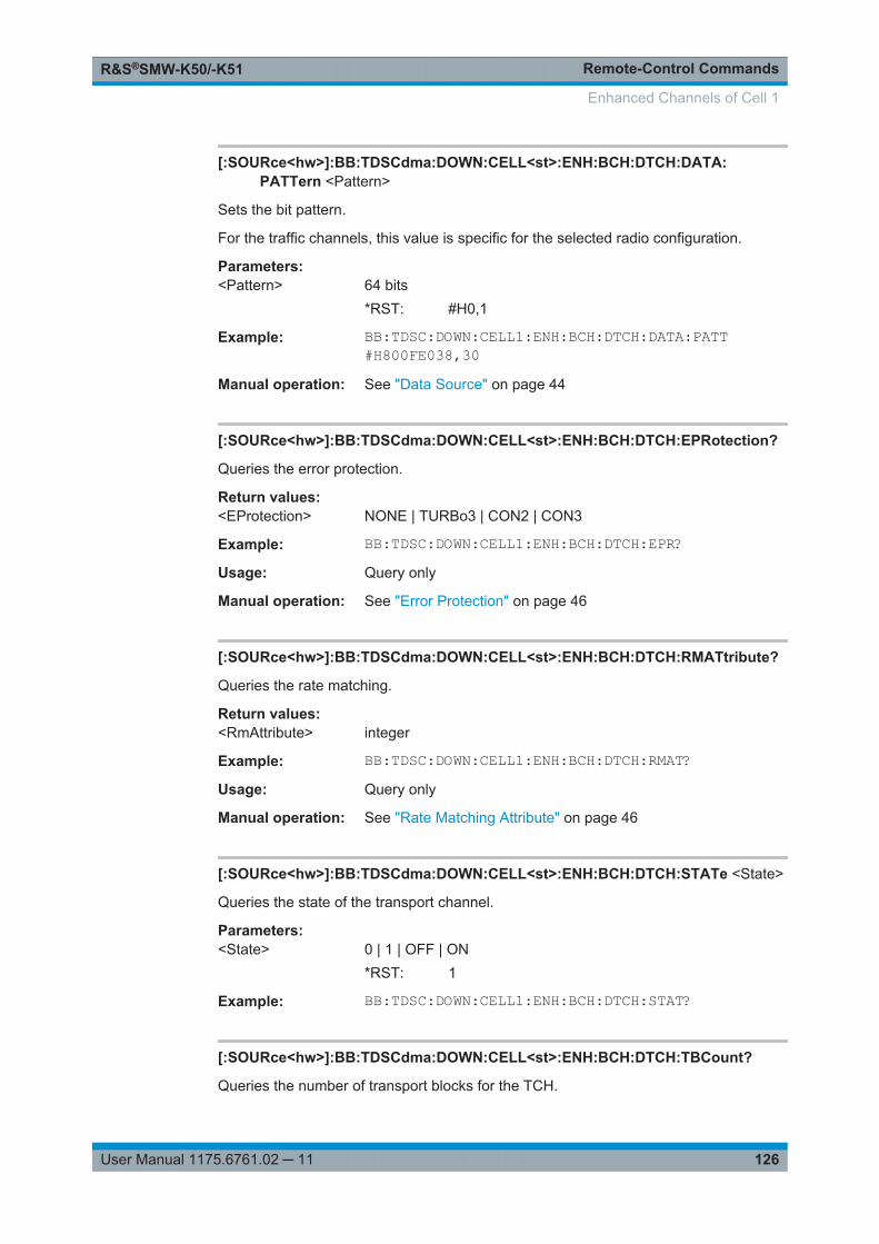
Remote-Control CommandsR&S®SMW-K50/-K51
126User Manual 1175.6761.02 ─ 11
[:SOURce<hw>]:BB:TDSCdma:DOWN:CELL<st>:ENH:BCH:DTCH:DATA:PATTern <Pattern>
Sets the bit pattern.
For the traffic channels, this value is specific for the selected radio configuration.
Parameters:<Pattern> 64 bits
*RST: #H0,1
Example: BB:TDSC:DOWN:CELL1:ENH:BCH:DTCH:DATA:PATT#H800FE038,30
Manual operation: See "Data Source" on page 44
[:SOURce<hw>]:BB:TDSCdma:DOWN:CELL<st>:ENH:BCH:DTCH:EPRotection?
Queries the error protection.
Return values: <EProtection> NONE | TURBo3 | CON2 | CON3
Example: BB:TDSC:DOWN:CELL1:ENH:BCH:DTCH:EPR?Usage: Query only
Manual operation: See "Error Protection" on page 46
[:SOURce<hw>]:BB:TDSCdma:DOWN:CELL<st>:ENH:BCH:DTCH:RMATtribute?
Queries the rate matching.
Return values: <RmAttribute> integer
Example: BB:TDSC:DOWN:CELL1:ENH:BCH:DTCH:RMAT?Usage: Query only
Manual operation: See "Rate Matching Attribute" on page 46
[:SOURce<hw>]:BB:TDSCdma:DOWN:CELL<st>:ENH:BCH:DTCH:STATe <State>
Queries the state of the transport channel.
Parameters:<State> 0 | 1 | OFF | ON
*RST: 1
Example: BB:TDSC:DOWN:CELL1:ENH:BCH:DTCH:STAT?
[:SOURce<hw>]:BB:TDSCdma:DOWN:CELL<st>:ENH:BCH:DTCH:TBCount?
Queries the number of transport blocks for the TCH.
Enhanced Channels of Cell 1
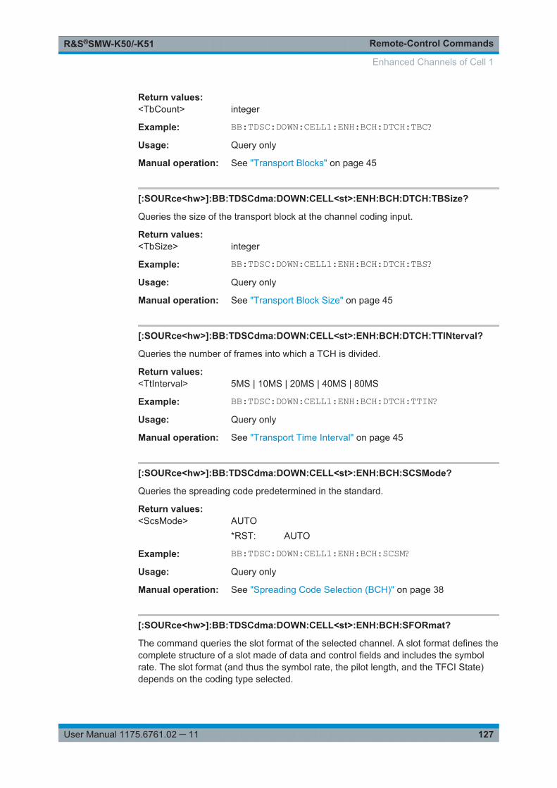
Remote-Control CommandsR&S®SMW-K50/-K51
127User Manual 1175.6761.02 ─ 11
Return values: <TbCount> integer
Example: BB:TDSC:DOWN:CELL1:ENH:BCH:DTCH:TBC?Usage: Query only
Manual operation: See "Transport Blocks" on page 45
[:SOURce<hw>]:BB:TDSCdma:DOWN:CELL<st>:ENH:BCH:DTCH:TBSize?
Queries the size of the transport block at the channel coding input.
Return values: <TbSize> integer
Example: BB:TDSC:DOWN:CELL1:ENH:BCH:DTCH:TBS?Usage: Query only
Manual operation: See "Transport Block Size" on page 45
[:SOURce<hw>]:BB:TDSCdma:DOWN:CELL<st>:ENH:BCH:DTCH:TTINterval?
Queries the number of frames into which a TCH is divided.
Return values: <TtInterval> 5MS | 10MS | 20MS | 40MS | 80MS
Example: BB:TDSC:DOWN:CELL1:ENH:BCH:DTCH:TTIN?Usage: Query only
Manual operation: See "Transport Time Interval" on page 45
[:SOURce<hw>]:BB:TDSCdma:DOWN:CELL<st>:ENH:BCH:SCSMode?
Queries the spreading code predetermined in the standard.
Return values: <ScsMode> AUTO
*RST: AUTO
Example: BB:TDSC:DOWN:CELL1:ENH:BCH:SCSM?Usage: Query only
Manual operation: See "Spreading Code Selection (BCH)" on page 38
[:SOURce<hw>]:BB:TDSCdma:DOWN:CELL<st>:ENH:BCH:SFORmat?
The command queries the slot format of the selected channel. A slot format defines thecomplete structure of a slot made of data and control fields and includes the symbolrate. The slot format (and thus the symbol rate, the pilot length, and the TFCI State)depends on the coding type selected.
Enhanced Channels of Cell 1
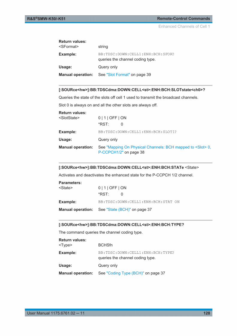
Remote-Control CommandsR&S®SMW-K50/-K51
128User Manual 1175.6761.02 ─ 11
Return values: <SFormat> string
Example: BB:TDSC:DOWN:CELL1:ENH:BCH:SFOR?queries the channel coding type.
Usage: Query only
Manual operation: See "Slot Format" on page 39
[:SOURce<hw>]:BB:TDSCdma:DOWN:CELL<st>:ENH:BCH:SLOTstate<ch0>?
Queries the state of the slots off cell 1 used to transmit the broadcast channels.
Slot 0 is always on and all the other slots are always off.
Return values: <SlotState> 0 | 1 | OFF | ON
*RST: 0
Example: BB:TDSC:DOWN:CELL1:ENH:BCH:SLOT1?Usage: Query only
Manual operation: See "Mapping On Physical Channels: BCH mapped to <Slot> 0,P-CCPCH1/2" on page 38
[:SOURce<hw>]:BB:TDSCdma:DOWN:CELL<st>:ENH:BCH:STATe <State>
Activates and deactivates the enhanced state for the P-CCPCH 1/2 channel.
Parameters:<State> 0 | 1 | OFF | ON
*RST: 0
Example: BB:TDSC:DOWN:CELL1:ENH:BCH:STAT ONManual operation: See "State (BCH)" on page 37
[:SOURce<hw>]:BB:TDSCdma:DOWN:CELL<st>:ENH:BCH:TYPE?
The command queries the channel coding type.
Return values: <Type> BCHSfn
Example: BB:TDSC:DOWN:CELL1:ENH:BCH:TYPE?queries the channel coding type.
Usage: Query only
Manual operation: See "Coding Type (BCH)" on page 37
Enhanced Channels of Cell 1
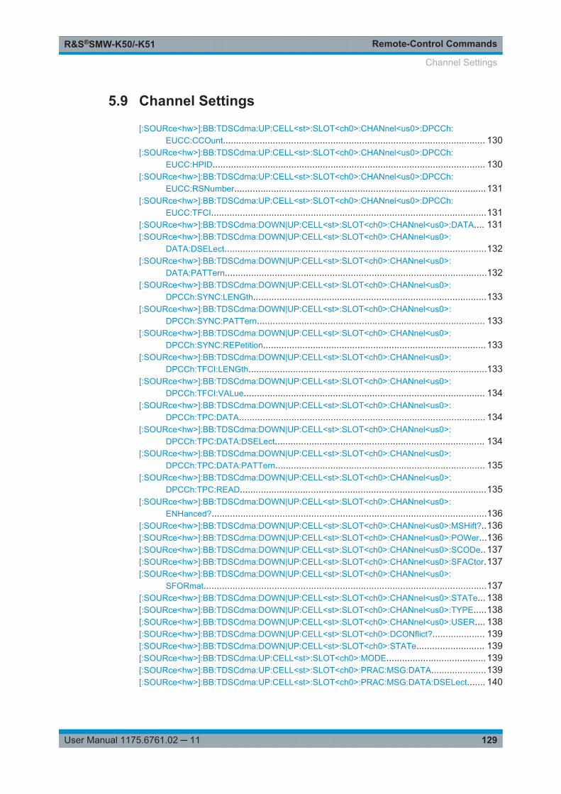
Remote-Control CommandsR&S®SMW-K50/-K51
129User Manual 1175.6761.02 ─ 11
5.9 Channel Settings
[:SOURce<hw>]:BB:TDSCdma:UP:CELL<st>:SLOT<ch0>:CHANnel<us0>:DPCCh:EUCC:CCOunt.................................................................................................... 130
[:SOURce<hw>]:BB:TDSCdma:UP:CELL<st>:SLOT<ch0>:CHANnel<us0>:DPCCh:EUCC:HPID........................................................................................................ 130
[:SOURce<hw>]:BB:TDSCdma:UP:CELL<st>:SLOT<ch0>:CHANnel<us0>:DPCCh:EUCC:RSNumber................................................................................................131
[:SOURce<hw>]:BB:TDSCdma:UP:CELL<st>:SLOT<ch0>:CHANnel<us0>:DPCCh:EUCC:TFCI.........................................................................................................131
[:SOURce<hw>]:BB:TDSCdma:DOWN|UP:CELL<st>:SLOT<ch0>:CHANnel<us0>:DATA.... 131[:SOURce<hw>]:BB:TDSCdma:DOWN|UP:CELL<st>:SLOT<ch0>:CHANnel<us0>:
DATA:DSELect....................................................................................................132[:SOURce<hw>]:BB:TDSCdma:DOWN|UP:CELL<st>:SLOT<ch0>:CHANnel<us0>:
DATA:PATTern....................................................................................................132[:SOURce<hw>]:BB:TDSCdma:DOWN|UP:CELL<st>:SLOT<ch0>:CHANnel<us0>:
DPCCh:SYNC:LENGth.........................................................................................133[:SOURce<hw>]:BB:TDSCdma:DOWN|UP:CELL<st>:SLOT<ch0>:CHANnel<us0>:
DPCCh:SYNC:PATTern....................................................................................... 133[:SOURce<hw>]:BB:TDSCdma:DOWN|UP:CELL<st>:SLOT<ch0>:CHANnel<us0>:
DPCCh:SYNC:REPetition.....................................................................................133[:SOURce<hw>]:BB:TDSCdma:DOWN|UP:CELL<st>:SLOT<ch0>:CHANnel<us0>:
DPCCh:TFCI:LENGth...........................................................................................133[:SOURce<hw>]:BB:TDSCdma:DOWN|UP:CELL<st>:SLOT<ch0>:CHANnel<us0>:
DPCCh:TFCI:VALue............................................................................................ 134[:SOURce<hw>]:BB:TDSCdma:DOWN|UP:CELL<st>:SLOT<ch0>:CHANnel<us0>:
DPCCh:TPC:DATA.............................................................................................. 134[:SOURce<hw>]:BB:TDSCdma:DOWN|UP:CELL<st>:SLOT<ch0>:CHANnel<us0>:
DPCCh:TPC:DATA:DSELect................................................................................ 134[:SOURce<hw>]:BB:TDSCdma:DOWN|UP:CELL<st>:SLOT<ch0>:CHANnel<us0>:
DPCCh:TPC:DATA:PATTern................................................................................ 135[:SOURce<hw>]:BB:TDSCdma:DOWN|UP:CELL<st>:SLOT<ch0>:CHANnel<us0>:
DPCCh:TPC:READ..............................................................................................135[:SOURce<hw>]:BB:TDSCdma:DOWN|UP:CELL<st>:SLOT<ch0>:CHANnel<us0>:
ENHanced?.........................................................................................................136[:SOURce<hw>]:BB:TDSCdma:DOWN|UP:CELL<st>:SLOT<ch0>:CHANnel<us0>:MSHift?..136[:SOURce<hw>]:BB:TDSCdma:DOWN|UP:CELL<st>:SLOT<ch0>:CHANnel<us0>:POWer...136[:SOURce<hw>]:BB:TDSCdma:DOWN|UP:CELL<st>:SLOT<ch0>:CHANnel<us0>:SCODe.. 137[:SOURce<hw>]:BB:TDSCdma:DOWN|UP:CELL<st>:SLOT<ch0>:CHANnel<us0>:SFACtor.137[:SOURce<hw>]:BB:TDSCdma:DOWN|UP:CELL<st>:SLOT<ch0>:CHANnel<us0>:
SFORmat............................................................................................................137[:SOURce<hw>]:BB:TDSCdma:DOWN|UP:CELL<st>:SLOT<ch0>:CHANnel<us0>:STATe... 138[:SOURce<hw>]:BB:TDSCdma:DOWN|UP:CELL<st>:SLOT<ch0>:CHANnel<us0>:TYPE.....138[:SOURce<hw>]:BB:TDSCdma:DOWN|UP:CELL<st>:SLOT<ch0>:CHANnel<us0>:USER.... 138[:SOURce<hw>]:BB:TDSCdma:DOWN|UP:CELL<st>:SLOT<ch0>:DCONflict?.................... 139[:SOURce<hw>]:BB:TDSCdma:DOWN|UP:CELL<st>:SLOT<ch0>:STATe.......................... 139[:SOURce<hw>]:BB:TDSCdma:UP:CELL<st>:SLOT<ch0>:MODE......................................139[:SOURce<hw>]:BB:TDSCdma:UP:CELL<st>:SLOT<ch0>:PRAC:MSG:DATA.....................139[:SOURce<hw>]:BB:TDSCdma:UP:CELL<st>:SLOT<ch0>:PRAC:MSG:DATA:DSELect....... 140
Channel Settings
Remote-Control CommandsR&S®SMW-K50/-K51
130User Manual 1175.6761.02 ─ 11
[:SOURce<hw>]:BB:TDSCdma:UP:CELL<st>:SLOT<ch0>:PRAC:MSG:DATA:PATTern.......140[:SOURce<hw>]:BB:TDSCdma:UP:CELL<st>:SLOT<ch0>:PRAC:MSG:LENGth..................141[:SOURce<hw>]:BB:TDSCdma:UP:CELL<st>:SLOT<ch0>:PRAC:MSG:MSHift?..................141[:SOURce<hw>]:BB:TDSCdma:UP:CELL<st>:SLOT<ch0>:PRAC:MSG:PCORrection.......... 141[:SOURce<hw>]:BB:TDSCdma:UP:CELL<st>:SLOT<ch0>:PRAC:MSG:POWer...................142[:SOURce<hw>]:BB:TDSCdma:UP:CELL<st>:SLOT<ch0>:PRAC:MSG:SCODe.................. 142[:SOURce<hw>]:BB:TDSCdma:UP:CELL<st>:SLOT<ch0>:PRAC:MSG:SFACtor................. 142[:SOURce<hw>]:BB:TDSCdma:UP:CELL<st>:SLOT<ch0>:PRAC:MSG:SFORmat?............. 142[:SOURce<hw>]:BB:TDSCdma:UP:CELL<st>:SLOT<ch0>:PRAC:MSG:STATe................... 143[:SOURce<hw>]:BB:TDSCdma:UP:CELL<st>:SLOT<ch0>:PRAC:MSG:USER.................... 143[:SOURce<hw>]:BB:TDSCdma:UP:CELL<st>:SLOT<ch0>:PRAC:PTS:DISTance................ 143[:SOURce<hw>]:BB:TDSCdma:UP:CELL<st>:SLOT<ch0>:PRAC:PTS:PCORrection?..........144[:SOURce<hw>]:BB:TDSCdma:UP:CELL<st>:SLOT<ch0>:PRAC:PTS:POWer....................144[:SOURce<hw>]:BB:TDSCdma:UP:CELL<st>:SLOT<ch0>:PRAC:PTS:PSTep.....................144[:SOURce<hw>]:BB:TDSCdma:UP:CELL<st>:SLOT<ch0>:PRAC:PTS:REPetition............... 145[:SOURce<hw>]:BB:TDSCdma:UP:CELL<st>:SLOT<ch0>:PRAC:PTS:STARt..................... 145[:SOURce<hw>]:BB:TDSCdma:UP:CELL<st>:SLOT<ch0>:PRAC:SLENgth?....................... 145
[:SOURce<hw>]:BB:TDSCdma:UP:CELL<st>:SLOT<ch0>:CHANnel<us0>:DPCCh:EUCC:CCOunt <CCount>
Sets the number of the E-DCH Uplink Control Channels (E-UCCH).
Parameters:<CCount> integer
Range: 0 to 8*RST: 0
Example: BB:TDSC:UP:CELL1:SLOT1:CHAN7:TYPE E_PUCH_QPSKsets channel type E-PUCH QPSKBB:TDSC:UP:CELL1:SLOT1:CHAN7:DPCC:EUCC:CCO 5sets number of E-UCCH channels
Manual operation: See "Number of E-UCCH Channels" on page 76
[:SOURce<hw>]:BB:TDSCdma:UP:CELL<st>:SLOT<ch0>:CHANnel<us0>:DPCCh:EUCC:HPID <Hpid>
Sets the HARQ process ID.
Parameters:<Hpid> integer
Range: 0 to 3*RST: 0
Example: BB:TDSC:UP:CELL1:SLOT1:CHAN7:TYPE E_PUCH_QPSKsets channel type E-PUCH QPSKBB:TDSC:UP:CELL1:SLOT1:CHAN7:DPCC:EUCC:HPID 2sets number HARQ process ID
Manual operation: See "HARQ Process ID" on page 76
Channel Settings
Remote-Control CommandsR&S®SMW-K50/-K51
131User Manual 1175.6761.02 ─ 11
[:SOURce<hw>]:BB:TDSCdma:UP:CELL<st>:SLOT<ch0>:CHANnel<us0>:DPCCh:EUCC:RSNumber <RsNumber>
Sets the retransmission sequence number.
Parameters:<RsNumber> integer
Range: 0 to 3*RST: 0
Example: BB:TDSC:UP:CELL1:SLOT1:CHAN7:TYPE E_PUCH_QPSKsets channel type E-PUCH QPSKBB:TDSC:UP:CELL1:SLOT1:CHAN7:DPCC:EUCC:RSN 2sets retransmission sequence number
Manual operation: See "Retransmission Sequence Number (E-UCCH)" on page 76
[:SOURce<hw>]:BB:TDSCdma:UP:CELL<st>:SLOT<ch0>:CHANnel<us0>:DPCCh:EUCC:TFCI <Tfci>
Enters the value of the TFCI field.
Parameters:<Tfci> integer
Range: 0 to 63*RST: 0
Example: BB:TDSC:UP:CELL1:SLOT1:CHAN7:TYPE E_PUCH_QPSKsets channel type E-PUCH QPSKBB:TDSC:UP:CELL1:SLOT1:CHAN7:DPCC:EUCC:TFCI 10sets the TFCI value
Manual operation: See "E-TFCI Value" on page 76
[:SOURce<hw>]:BB:TDSCdma:DOWN|UP:CELL<st>:SLOT<ch0>:CHANnel<us0>:DATA <Data>
The command determines the data source for the selected channel.
Channel Settings
Remote-Control CommandsR&S®SMW-K50/-K51
132User Manual 1175.6761.02 ─ 11
Parameters:<Data> PN9 | PN11 | PN15 | PN16 | PN20 | PN21 | PN23 | DLISt |
ZERO | ONE | PATTernPNxxPRBS data as per CCITT with period lengths between 29-1 and223-1 is generated internally.DLIStInternal data from a programmable data list is used.ZERO | ONEInternal 0 and 1 data is used.PATTernA user-definable bit pattern with a maximum length of 64 bits isgenerated internally.*RST: PN9
Example: BB:TDSC:DOWN:CELL4:SLOT3:CHAN6:DATA PN9sets the data source for the selected channel to PN9.
Manual operation: See "Data" on page 68
[:SOURce<hw>]:BB:TDSCdma:DOWN|UP:CELL<st>:SLOT<ch0>:CHANnel<us0>:DATA:DSELect <DSelect>
Selects an existing data list file from the default directory or from the specific directory.
Parameters:<DSelect> string
Example: BB:TDSC:UP:CELL1:SLOT3:CHAN6:DATA DLISMMEM:CDIR "/var/user/Lists"BB:TDSC:UP:CELL1:SLOT3:CHAN6:DATA:DSEL"tdscdma_1"selects file tdscdma_1 as the data source. This file must be inthe directory and must have the file extension *.dm_iqd.
Manual operation: See "Data" on page 68
[:SOURce<hw>]:BB:TDSCdma:DOWN|UP:CELL<st>:SLOT<ch0>:CHANnel<us0>:DATA:PATTern <Pattern>
Determines the bit pattern. The first parameter determines the bit pattern (choice ofhexadecimal, octal, or binary notation), the second specifies the number of bits to use.
Parameters:<Pattern> 64 bits
*RST: #H0,1
Example: BB:TDSC:UP:CELL1:SLOT3:CHAN6:DATA:PATT #H3F, 8defines the bit pattern.
Manual operation: See "Data" on page 68
Channel Settings
Remote-Control CommandsR&S®SMW-K50/-K51
133User Manual 1175.6761.02 ─ 11
[:SOURce<hw>]:BB:TDSCdma:DOWN|UP:CELL<st>:SLOT<ch0>:CHANnel<us0>:DPCCh:SYNC:LENGth <Length>
Sets the length of the sync shift and the length of the TPC field in bits. The availablevalues depend on the slot format.
Parameters:<Length> 0 | 2 | 3 | 4 | 8 | 16 | 32 | 48
*RST: 0
Example: BB:TDSC:DOWN:CELL4:SLOT3:CHAN6:DPCC:SYNC:LENG 2Manual operation: See "Number of Sync Shift & TPC Bits" on page 74
[:SOURce<hw>]:BB:TDSCdma:DOWN|UP:CELL<st>:SLOT<ch0>:CHANnel<us0>:DPCCh:SYNC:PATTern <Pattern>
Sets the bit pattern for the sync shift.
Parameters:<Pattern> string
The maximum pattern length is 64 bits.
Example: BB:TDSC:DOWN:CELL4:SLOT3:CHAN6:DPCC:SYNC:PATT10-01
Manual operation: See "Sync Shift Pattern" on page 74
[:SOURce<hw>]:BB:TDSCdma:DOWN|UP:CELL<st>:SLOT<ch0>:CHANnel<us0>:DPCCh:SYNC:REPetition <Repetition>
Sets the value for the sync shift repetition.
Parameters:<Repetition> integer
Range: 1 to 8*RST: 1
Example: BB:TDSC:DOWN:CELL4:SLOT3:CHAN6:DPCC:SYNC:REP 1Manual operation: See "Sync Shift Repetition M" on page 75
[:SOURce<hw>]:BB:TDSCdma:DOWN|UP:CELL<st>:SLOT<ch0>:CHANnel<us0>:DPCCh:TFCI:LENGth <Length>
Sets the length of the TFCI field in bits.
Parameters:<Length> 0 | 4 | 6 | 8 | 12 | 16 | 24 | 32 | 48
*RST: 0
Channel Settings
Remote-Control CommandsR&S®SMW-K50/-K51
134User Manual 1175.6761.02 ─ 11
Example: BB:TDSC:DOWN:CELL4:SLOT3:CHAN6:DPCC:TFCI:LENG12sets the length of the TFCI field to 12 bits.
Manual operation: See "Number of TFCI Bits" on page 73
[:SOURce<hw>]:BB:TDSCdma:DOWN|UP:CELL<st>:SLOT<ch0>:CHANnel<us0>:DPCCh:TFCI:VALue <Value>
The command sets the value of the TFCI field.
Parameters:<Value> integer
Range: 0 to 1023*RST: 0
Example: BB:TDSC:DOWN:CELL4:SLOT3:CHAN6:DPCC:TFCI:VAL 0sets the value of the TFCI field to 0.
Manual operation: See "TFCI Value" on page 73
[:SOURce<hw>]:BB:TDSCdma:DOWN|UP:CELL<st>:SLOT<ch0>:CHANnel<us0>:DPCCh:TPC:DATA <Data>
Sets the data source for the TPC field of the DPCCH.
Parameters:<Data> ZERO | ONE | PATTern | DLISt
DLIStA data list is used.ZERO | ONEInternal 0 and 1 data is used.PATTernInternal data is used.*RST: PATTern
Example: BB:TDSC:DOWN:CELL4:SLOT3:CHAN6:DPCC:TPC:DATAPATTBB:TDSC:DOWN:CELL4:SLOT3:CHAN6:DPCC:TPC:DATA:PATT #H3F,8
Manual operation: See "TPC Source" on page 77
[:SOURce<hw>]:BB:TDSCdma:DOWN|UP:CELL<st>:SLOT<ch0>:CHANnel<us0>:DPCCh:TPC:DATA:DSELect <DSelect>
Selects an existing data list file from the default directory or from the specific directory.
For the traffic channels, this value is specific for the selected radio configuration.
Parameters:<DSelect> string
Channel Settings
Remote-Control CommandsR&S®SMW-K50/-K51
135User Manual 1175.6761.02 ─ 11
Example: BB:TDSC:DOWN:CELL1:SLOT3:CHAN5:DPCC:TPC:DATADLISMMEM:CDIR "/var/user/Lists"BB:TDSC:DOWN:CELL1:SLOT3:CHAN5:DPCC:TPC:DATA:DSEL "tdscdma_1"selects file tdscdma_1 as the data source. This file must be inthe directory and must have the file extension *.dm_iqd.
Manual operation: See "TPC Source" on page 77
[:SOURce<hw>]:BB:TDSCdma:DOWN|UP:CELL<st>:SLOT<ch0>:CHANnel<us0>:DPCCh:TPC:DATA:PATTern <Pattern>
Sets the bit pattern. The maximum bit pattern length is 64 bits.
Parameters:<Pattern> 64 bits
*RST: #H1,2
Example: BB:TDSC:DOWN:CELL4:SLOT3:CHAN6:DPCC:TPC:DATA:PATT #H3F,8defines the bit pattern.
Manual operation: See "TPC Source" on page 77
[:SOURce<hw>]:BB:TDSCdma:DOWN|UP:CELL<st>:SLOT<ch0>:CHANnel<us0>:DPCCh:TPC:READ <Read>
Sets the read out mode for the bit pattern of the TPC field.
Parameters:<Read> CONTinuous | S0A | S1A | S01A | S10A
CONTinousThe TPC bits are used cyclically.S0AThe TPC bits are used once and then the TPC sequence is con-tinued with 0 bits.S1AThe TPC bits are used once and then the TPC sequence is con-tinued with 1 bit.S01AThe TPC bits are used once and then the TPC sequence is con-tinued with 0 and 1 bits alternatelyS10AThe TPC bits are used once, and then the TPC sequence iscontinued with 1 and 0 bits alternately*RST: CONTinuous
Example: BB:TDSC:DOWN:CELL4:SLOT3:CHAN6:DPCC:TPC:READS01A
Channel Settings
Remote-Control CommandsR&S®SMW-K50/-K51
136User Manual 1175.6761.02 ─ 11
Manual operation: See "Read Out Mode" on page 78
[:SOURce<hw>]:BB:TDSCdma:DOWN|UP:CELL<st>:SLOT<ch0>:CHANnel<us0>:ENHanced?
Queries the enhanced state. If the enhanced state is set to ON, the channel codingcannot be changed.
Return values: <Enhanced> 0 | 1 | 2 | OFF | ON | NOvalue
*RST: NOvalue
Example: BB:TDSC:DOWN:CELL4:SLOT3:CHAN6:ENH?Usage: Query only
Manual operation: See "Enhanced" on page 67
[:SOURce<hw>]:BB:TDSCdma:DOWN|UP:CELL<st>:SLOT<ch0>:CHANnel<us0>:MSHift?
Queries the midamble shift.
Return values: <MShift> integer
Range: 0 to 128*RST: 120
Example: BB:TDSC:DOWN:CELL4:SLOT3:CHAN6:MSH?Usage: Query only
Manual operation: See "Midamble Shift" on page 73
[:SOURce<hw>]:BB:TDSCdma:DOWN|UP:CELL<st>:SLOT<ch0>:CHANnel<us0>:POWer <Power>
Sets the channel power in dB.
Parameters:<Power> float
Range: -80 to 0Increment: 0.01*RST: 0
Example: BB:TDSC:DOWN:CELL4:SLOT3:CHAN6:POW -20Manual operation: See "Power/dB" on page 68
Channel Settings
Remote-Control CommandsR&S®SMW-K50/-K51
137User Manual 1175.6761.02 ─ 11
[:SOURce<hw>]:BB:TDSCdma:DOWN|UP:CELL<st>:SLOT<ch0>:CHANnel<us0>:SCODe <SCode>
Sets the spreading code for the selected channel. The code channel is spread with theset spreading code. The range of values of the spreading code depends on the chan-nel type and the spreading factor. Depending on the channel type, the range of valuescan be limited.
Parameters:<SCode> integer
Range: 1 to 16*RST: 1
Example: BB:TDSC:DOWN:CELL4:SLOT3:CHAN6:SCOD 1set the spreading code for channel 6 to 1.
Manual operation: See "Sprd. Code" on page 68
[:SOURce<hw>]:BB:TDSCdma:DOWN|UP:CELL<st>:SLOT<ch0>:CHANnel<us0>:SFACtor <SFactor>
Sets the spreading factor for the selected channel. The selection depends on the chan-nel type and interacts with the slot format.
Parameters:<SFactor> 1 | 2 | 4 | 8 | 16
*RST: 16
Example: BB:TDSC:DOWN:CELL4:SLOT3:CHAN6:SFAC 16Manual operation: See "Sprd. Fact." on page 68
[:SOURce<hw>]:BB:TDSCdma:DOWN|UP:CELL<st>:SLOT<ch0>:CHANnel<us0>:SFORmat <SFormat>
Sets the slot format for the selected channel. A slot format defines the complete struc-ture of a slot made of data and control fields and includes the symbol rate. The slotformat displays changes when a change is made to the "Number of TFCI Bits" and the"Number of Sync Shift & TPC Bits" field settings.
Parameters:<SFormat> integer
Range: 0 to 69*RST: -
Example: BB:TDSC:DOWN:CELL4:SLOT3:CHAN6:SFOR 0sets the slot format for channel 6 to 0.
Manual operation: See "Slot Format" on page 67
Channel Settings
Remote-Control CommandsR&S®SMW-K50/-K51
138User Manual 1175.6761.02 ─ 11
[:SOURce<hw>]:BB:TDSCdma:DOWN|UP:CELL<st>:SLOT<ch0>:CHANnel<us0>:STATe <State>
Activates or deactivates the channel.
Parameters:<State> 0 | 1 | OFF | ON
*RST: 0
Example: BB:TDSC:UP:CELL1:SLOT3:CHAN6:STAT ONManual operation: See "State" on page 69
[:SOURce<hw>]:BB:TDSCdma:DOWN|UP:CELL<st>:SLOT<ch0>:CHANnel<us0>:TYPE <Type>
Sets the channel type.
In the uplink, the channel type is fixed for channel number 0. In the downlink, the chan-nel type is fixed for channel numbers 0 to 5. For the remaining numbers, the choice liesbetween the relevant standard channels and the high speed channels.
Parameters:<Type> P_CCPCH1 | P_CCPCH2 | S_CCPCH1 | S_CCPCH2 | FPACH |
PDSCH | DPCH_QPSQ | DPCH_8PSQ | HS_SCCH1 |HS_SCCH2 | HS_PDS_QPSK | HS_PDS_16QAM | PUSCH |UP_DPCH_QPSK | UP_DPCH_8PSK | HS_SICH |HS_PDS_64QAM | E_PUCH_QPSK | E_PUCH_16QAM |E_RUCCH | PLCCH | EAGCH | EHICH*RST: depends on channel number
Example: BB:TDSC:DOWN:CELL4:SLOT3:CHAN6:TYPE DPC_QPSKsets the channel type DPC_QPSK for channel 6 of the channeltable.
Manual operation: See "Channel Type" on page 67
[:SOURce<hw>]:BB:TDSCdma:DOWN|UP:CELL<st>:SLOT<ch0>:CHANnel<us0>:USER <User>
Sets the number of the user.
Parameters:<User> integer
Range: 1 to 16*RST: 1
Example: BB:TDSC:DOWN:CELL4:SLOT3:CHAN6:USER 3sets the number of the users to 3.
Manual operation: See "Crt.User/Mid.Shift" on page 67
Channel Settings
Remote-Control CommandsR&S®SMW-K50/-K51
139User Manual 1175.6761.02 ─ 11
[:SOURce<hw>]:BB:TDSCdma:DOWN|UP:CELL<st>:SLOT<ch0>:DCONflict?
Queries the global domain conflict state per slot.
Return values: <DConflict> 0 | 1 | OFF | ON
*RST: 0
Example: BB:TDSC:UP:CELL1:SLOT3:DCON?Usage: Query only
Manual operation: See "Dom. Conf." on page 69
[:SOURce<hw>]:BB:TDSCdma:DOWN|UP:CELL<st>:SLOT<ch0>:STATe <State>
Activates and deactivates the slot in the subframe.
Parameters:<State> 0 | 1 | OFF | ON
*RST: 0
Example: BB:TDSC:DOWN:CELL1:SLOT0:STAT ONManual operation: See "Slot Icon" on page 36
[:SOURce<hw>]:BB:TDSCdma:UP:CELL<st>:SLOT<ch0>:MODE <Mode>
Sets the mode in which the slot is to work.
Parameters:<Mode> DEDicated | PRACh
DEDicatedThe instrument generates a signal with a dedicated physicalcontrol channel (DPCCH) and up to six dedicated physical datachannels (DPDCH). The signal is used for voice and data trans-mission.PRAChThe instrument generates a single physical random accesschannel (PRACH). This channel is needed to set up the connec-tion between the mobile station and the base station.*RST: DEDicated
Example: BB:TDSC:UP:CELL4:SLOT3:MODE PRACManual operation: See "Slot Mode" on page 64
[:SOURce<hw>]:BB:TDSCdma:UP:CELL<st>:SLOT<ch0>:PRAC:MSG:DATA<Data>
The command determines the data source for the PRACH.
Channel Settings
Remote-Control CommandsR&S®SMW-K50/-K51
140User Manual 1175.6761.02 ─ 11
Parameters:<Data> PN9 | PN11 | PN15 | PN16 | PN20 | PN21 | PN23 | DLISt |
ZERO | ONE | PATTernPNxxPRBS data as per CCITT with period lengths between 29-1 and223-1 is generated internally.DLIStInternal data from a programmable data list is used.ZERO | ONEInternal 0 and 1 data is used.PATTernA user-definable bit pattern with a maximum length of 64 bits isgenerated internally.*RST: PN9
Example: BB:TDSC:UP:CELL4:SLOT3:PRAC:MSG:DATA PN9selects PN9 as the data source for the PRACH.
Manual operation: See " Data Source (PRACH) " on page 82
[:SOURce<hw>]:BB:TDSCdma:UP:CELL<st>:SLOT<ch0>:PRAC:MSG:DATA:DSELect <DSelect>
Selects an existing data list file from the default directory or from the specific directory.
Parameters:<DSelect> string
Filename incl. file extension or complete file path
Example: BB:TDSC:UP:CELL1:SLOT3:PRAC:MSG:DATA DLISMMEM:CDIR "/var/user/Lists"BB:TDSC:UP:CELL1:SLOT3:PRAC:MSG:DATA:DSEL"tdscdma_1"Selects file tdscdma_1 as the data source. This file must be inthe directory and it must have the file extension *.dm_iqd
Manual operation: See " Data Source (PRACH) " on page 82
[:SOURce<hw>]:BB:TDSCdma:UP:CELL<st>:SLOT<ch0>:PRAC:MSG:DATA:PATTern <Pattern>
Determines the bit pattern. The first parameter determines the bit pattern (choice ofhexadecimal, octal or binary notation), the second specifies the number of bits to use.
Parameters:<Pattern> 64 bits
*RST: #H0,1
Channel Settings
Remote-Control CommandsR&S®SMW-K50/-K51
141User Manual 1175.6761.02 ─ 11
Example: BB:TDSC:UP:CELL1:SLOT3:PRAC:MSG:DATA:PATT #H3F,8defines the bit pattern.
Manual operation: See " Data Source (PRACH) " on page 82
[:SOURce<hw>]:BB:TDSCdma:UP:CELL<st>:SLOT<ch0>:PRAC:MSG:LENGth<Length>
Sets the message length of the random access channel in subframes.
Parameters:<Length> 1 | 2 | 4
*RST: 1
Example: BB:TDSC:UP:CELL4:SLOT3:PRAC:MSG:LENG 1Manual operation: See " Message Length " on page 82
[:SOURce<hw>]:BB:TDSCdma:UP:CELL<st>:SLOT<ch0>:PRAC:MSG:MSHift?
Queries the value of the midamble shift.
Return values: <MShift> integer
Range: 0 to 128*RST: 120
Example: BB:TDSC:UP:CELL1:SLOT3:PRAC:MSG:MSH?Usage: Query only
Manual operation: See " Midamble Shift (PRACH) " on page 83
[:SOURce<hw>]:BB:TDSCdma:UP:CELL<st>:SLOT<ch0>:PRAC:MSG:PCORrection <PCorrection>
Queries the value of the power correction.
Parameters:<PCorrection> float
Range: -1E10 to 1E10Increment: 0.01*RST: -
Example: BB:TDSC:UP:CELL4:SLOT3:PRAC:MSG:POW -10sets the power of the PRACH message partBB:TDSC:UP:CELL4:SLOT3:PRAC:MSG:PCOR?queries the value of the power correction.Response: 2.99086185076844
Manual operation: See " Power (RACH Message Part) " on page 82
Channel Settings
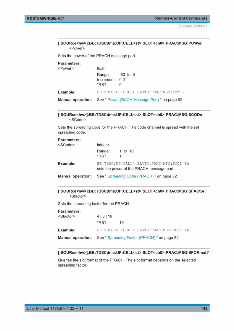
Remote-Control CommandsR&S®SMW-K50/-K51
142User Manual 1175.6761.02 ─ 11
[:SOURce<hw>]:BB:TDSCdma:UP:CELL<st>:SLOT<ch0>:PRAC:MSG:POWer<Power>
Sets the power of the PRACH message part.
Parameters:<Power> float
Range: -80 to 0Increment: 0.01*RST: 0
Example: BB:TDSC:UP:CELL4:SLOT3:PRAC:MSG:POW 1Manual operation: See " Power (RACH Message Part) " on page 82
[:SOURce<hw>]:BB:TDSCdma:UP:CELL<st>:SLOT<ch0>:PRAC:MSG:SCODe<SCode>
Sets the spreading code for the PRACH. The code channel is spread with the setspreading code.
Parameters:<SCode> integer
Range: 1 to 16*RST: 1
Example: BB:TDSC:UP:CELL4:SLOT3:PRAC:MSG:SCOD 16sets the power of the PRACH message part.
Manual operation: See " Spreading Code (PRACH) " on page 82
[:SOURce<hw>]:BB:TDSCdma:UP:CELL<st>:SLOT<ch0>:PRAC:MSG:SFACtor<Sfactor>
Sets the spreading factor for the PRACH.
Parameters:<Sfactor> 4 | 8 | 16
*RST: 16
Example: BB:TDSC:UP:CELL4:SLOT3:PRAC:MSG:SFAC 16Manual operation: See " Spreading Factor (PRACH) " on page 82
[:SOURce<hw>]:BB:TDSCdma:UP:CELL<st>:SLOT<ch0>:PRAC:MSG:SFORmat?
Queries the slot format of the PRACH. The slot format depends on the selectedspreading factor.
Channel Settings

Remote-Control CommandsR&S®SMW-K50/-K51
143User Manual 1175.6761.02 ─ 11
Return values: <SFormat> integer
Range: 0 to 25*RST: 0
Example: BB:TDSC:UP:CELL4:SLOT3:PRAC:MSG:SFOR 1Usage: Query only
Manual operation: See " Slot Format (PRACH) " on page 82
[:SOURce<hw>]:BB:TDSCdma:UP:CELL<st>:SLOT<ch0>:PRAC:MSG:STATe<State>
Activates or deactivates the RACH (random access channel) message part.
Parameters:<State> 0 | 1 | OFF | ON
*RST: 0
Example: BB:TDSC:UP:CELL4:SLOT3:PRAC:MSG:STAT ONManual operation: See " State (RACH Message Part) " on page 81
[:SOURce<hw>]:BB:TDSCdma:UP:CELL<st>:SLOT<ch0>:PRAC:MSG:USER<User>
Sets user number.
Parameters:<User> integer
Range: 1 to 16*RST: 1
Example: BB:TDSC:UP:CELL1:SLOT3:PRAC:MSG:USER 1Manual operation: See " Current User (PRACH) " on page 83
[:SOURce<hw>]:BB:TDSCdma:UP:CELL<st>:SLOT<ch0>:PRAC:PTS:DISTance<Distance>
Sets the value to vary the timing between UpPTS and RACH.
Parameters:<Distance> integer
Range: 1 to 4*RST: 1
Example: BB:TDSC:UP:CELL4:SLOT3:PRAC:PTS:DIST 1Manual operation: See " Distance UpPTS " on page 80
Channel Settings
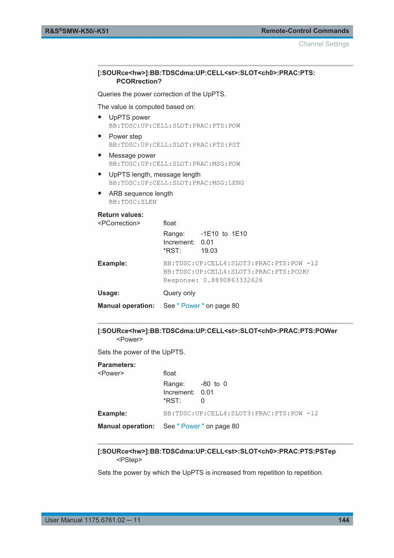
Remote-Control CommandsR&S®SMW-K50/-K51
144User Manual 1175.6761.02 ─ 11
[:SOURce<hw>]:BB:TDSCdma:UP:CELL<st>:SLOT<ch0>:PRAC:PTS:PCORrection?
Queries the power correction of the UpPTS.
The value is computed based on:● UpPTS power
BB:TDSC:UP:CELL:SLOT:PRAC:PTS:POW● Power step
BB:TDSC:UP:CELL:SLOT:PRAC:PTS:PST● Message power
BB:TDSC:UP:CELL:SLOT:PRAC:MSG:POW● UpPTS length, message length
BB:TDSC:UP:CELL:SLOT:PRAC:MSG:LENG● ARB sequence length
BB:TDSC:SLENReturn values: <PCorrection> float
Range: -1E10 to 1E10Increment: 0.01*RST: 19.03
Example: BB:TDSC:UP:CELL4:SLOT3:PRAC:PTS:POW -12BB:TDSC:UP:CELL4:SLOT3:PRAC:PTS:PCOR?Response: 0.8890863332626
Usage: Query only
Manual operation: See " Power " on page 80
[:SOURce<hw>]:BB:TDSCdma:UP:CELL<st>:SLOT<ch0>:PRAC:PTS:POWer<Power>
Sets the power of the UpPTS.
Parameters:<Power> float
Range: -80 to 0Increment: 0.01*RST: 0
Example: BB:TDSC:UP:CELL4:SLOT3:PRAC:PTS:POW -12Manual operation: See " Power " on page 80
[:SOURce<hw>]:BB:TDSCdma:UP:CELL<st>:SLOT<ch0>:PRAC:PTS:PSTep<PStep>
Sets the power by which the UpPTS is increased from repetition to repetition.
Channel Settings
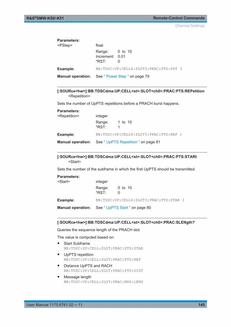
Remote-Control CommandsR&S®SMW-K50/-K51
145User Manual 1175.6761.02 ─ 11
Parameters:<PStep> float
Range: 0 to 10Increment: 0.01*RST: 0
Example: BB:TDSC:UP:CELL4:SLOT3:PRAC:PTS:PST 3Manual operation: See " Power Step " on page 79
[:SOURce<hw>]:BB:TDSCdma:UP:CELL<st>:SLOT<ch0>:PRAC:PTS:REPetition<Repetition>
Sets the number of UpPTS repetitions before a PRACH burst happens.
Parameters:<Repetition> integer
Range: 1 to 10*RST: 1
Example: BB:TDSC:UP:CELL4:SLOT3:PRAC:PTS:REP 1Manual operation: See " UpPTS Repetition " on page 81
[:SOURce<hw>]:BB:TDSCdma:UP:CELL<st>:SLOT<ch0>:PRAC:PTS:STARt<Start>
Sets the number of the subframe in which the first UpPTS should be transmitted.
Parameters:<Start> integer
Range: 0 to 10*RST: 0
Example: BB:TDSC:UP:CELL4:SLOT3:PRAC:PTS:STAR 3Manual operation: See " UpPTS Start " on page 80
[:SOURce<hw>]:BB:TDSCdma:UP:CELL<st>:SLOT<ch0>:PRAC:SLENgth?
Queries the sequence length of the PRACH slot.
The value is computed based on:● Start Subframe
BB:TDSC:UP:CELL:SLOT:PRAC:PTS:STAR● UpPTS repetition
BB:TDSC:UP:CELL:SLOT:PRAC:PTS:REP● Distance UpPTS and RACH
BB:TDSC:UP:CELL:SLOT:PRAC:PTS:DIST● Message length
BB:TDSC:UP:CELL:SLOT:PRAC:MSG:LENG
Channel Settings
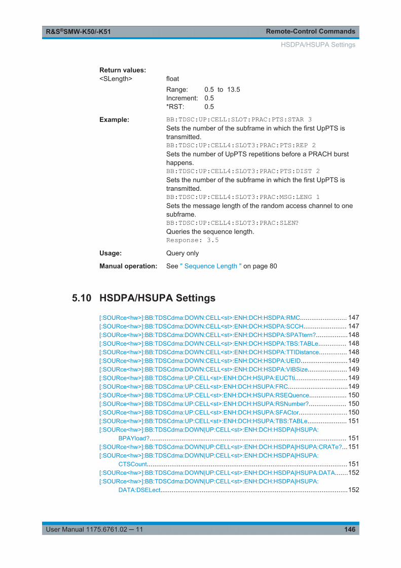
Remote-Control CommandsR&S®SMW-K50/-K51
146User Manual 1175.6761.02 ─ 11
Return values: <SLength> float
Range: 0.5 to 13.5Increment: 0.5*RST: 0.5
Example: BB:TDSC:UP:CELL:SLOT:PRAC:PTS:STAR 3Sets the number of the subframe in which the first UpPTS istransmitted.BB:TDSC:UP:CELL4:SLOT3:PRAC:PTS:REP 2Sets the number of UpPTS repetitions before a PRACH bursthappens.BB:TDSC:UP:CELL4:SLOT3:PRAC:PTS:DIST 2Sets the number of the subframe in which the first UpPTS istransmitted.BB:TDSC:UP:CELL4:SLOT3:PRAC:MSG:LENG 1Sets the message length of the random access channel to onesubframe.BB:TDSC:UP:CELL4:SLOT3:PRAC:SLEN?Queries the sequence length.Response: 3.5
Usage: Query only
Manual operation: See " Sequence Length " on page 80
5.10 HSDPA/HSUPA Settings
[:SOURce<hw>]:BB:TDSCdma:DOWN:CELL<st>:ENH:DCH:HSDPA:RMC......................... 147[:SOURce<hw>]:BB:TDSCdma:DOWN:CELL<st>:ENH:DCH:HSDPA:SCCH....................... 147[:SOURce<hw>]:BB:TDSCdma:DOWN:CELL<st>:ENH:DCH:HSDPA:SPATtern?.................148[:SOURce<hw>]:BB:TDSCdma:DOWN:CELL<st>:ENH:DCH:HSDPA:TBS:TABLe............... 148[:SOURce<hw>]:BB:TDSCdma:DOWN:CELL<st>:ENH:DCH:HSDPA:TTIDistance............... 148[:SOURce<hw>]:BB:TDSCdma:DOWN:CELL<st>:ENH:DCH:HSDPA:UEID.........................149[:SOURce<hw>]:BB:TDSCdma:DOWN:CELL<st>:ENH:DCH:HSDPA:VIBSize..................... 149[:SOURce<hw>]:BB:TDSCdma:UP:CELL<st>:ENH:DCH:HSUPA:EUCTti............................149[:SOURce<hw>]:BB:TDSCdma:UP:CELL<st>:ENH:DCH:HSUPA:FRC................................149[:SOURce<hw>]:BB:TDSCdma:UP:CELL<st>:ENH:DCH:HSUPA:RSEQuence.................... 150[:SOURce<hw>]:BB:TDSCdma:UP:CELL<st>:ENH:DCH:HSUPA:RSNumber?.................... 150[:SOURce<hw>]:BB:TDSCdma:UP:CELL<st>:ENH:DCH:HSUPA:SFACtor..........................150[:SOURce<hw>]:BB:TDSCdma:UP:CELL<st>:ENH:DCH:HSUPA:TBS:TABLe..................... 151[:SOURce<hw>]:BB:TDSCdma:DOWN|UP:CELL<st>:ENH:DCH:HSDPA|HSUPA:
BPAYload?......................................................................................................... 151[:SOURce<hw>]:BB:TDSCdma:DOWN|UP:CELL<st>:ENH:DCH:HSDPA|HSUPA:CRATe?...151[:SOURce<hw>]:BB:TDSCdma:DOWN|UP:CELL<st>:ENH:DCH:HSDPA|HSUPA:
CTSCount...........................................................................................................151[:SOURce<hw>]:BB:TDSCdma:DOWN|UP:CELL<st>:ENH:DCH:HSDPA|HSUPA:DATA.......152[:SOURce<hw>]:BB:TDSCdma:DOWN|UP:CELL<st>:ENH:DCH:HSDPA|HSUPA:
DATA:DSELect....................................................................................................152
HSDPA/HSUPA Settings
Remote-Control CommandsR&S®SMW-K50/-K51
147User Manual 1175.6761.02 ─ 11
[:SOURce<hw>]:BB:TDSCdma:DOWN|UP:CELL<st>:ENH:DCH:HSDPA|HSUPA:DATA:PATTern....................................................................................................153
[:SOURce<hw>]:BB:TDSCdma:DOWN|UP:CELL<st>:ENH:DCH:HSDPA|HSUPA:HARQ:LENGth.................................................................................................... 153
[:SOURce<hw>]:BB:TDSCdma:DOWN|UP:CELL<st>:ENH:DCH:HSDPA|HSUPA:HARQ:MODE...................................................................................................... 153
[:SOURce<hw>]:BB:TDSCdma:DOWN|UP:CELL<st>:ENH:DCH:HSDPA|HSUPA:MIBT?......154[:SOURce<hw>]:BB:TDSCdma:DOWN|UP:CELL<st>:ENH:DCH:HSDPA|HSUPA:
MODulation.........................................................................................................154[:SOURce<hw>]:BB:TDSCdma:DOWN|UP:CELL<st>:ENH:DCH:HSDPA|HSUPA:NCBTti?...155[:SOURce<hw>]:BB:TDSCdma:DOWN|UP:CELL<st>:ENH:DCH:HSDPA|HSUPA:
RVParameter...................................................................................................... 155[:SOURce<hw>]:BB:TDSCdma:DOWN|UP:CELL<st>:ENH:DCH:HSDPA|HSUPA:
RVSequence.......................................................................................................155[:SOURce<hw>]:BB:TDSCdma:DOWN|UP:CELL<st>:ENH:DCH:HSDPA|HSUPA:
SFORmat?..........................................................................................................156[:SOURce<hw>]:BB:TDSCdma:DOWN|UP:CELL<st>:ENH:DCH:HSDPA|HSUPA:TBS:
INDex................................................................................................................. 156[:SOURce<hw>]:BB:TDSCdma:DOWN|UP:CELL<st>:ENH:DCH:HSDPA|HSUPA:TSCount.. 156[:SOURce<hw>]:BB:TDSCdma:DOWN|UP:CELL<st>:ENH:DCH:HSDPA|HSUPA:
TTINterval?......................................................................................................... 157[:SOURce<hw>]:BB:TDSCdma:DOWN|UP:CELL<st>:ENH:DCH:HSDPA|HSUPA:
UECategory?.......................................................................................................157
[:SOURce<hw>]:BB:TDSCdma:DOWN:CELL<st>:ENH:DCH:HSDPA:RMC <Rmc>
Enables a predefined set of RMC channels or fully configurable user mode.
Parameters:<Rmc> HRMC_0M5_QPSK | HRMC_1M1_QPSK |
HRMC_1M1_16QAM | HRMC_1M6_QPSK |HRMC_1M6_16QAM | HRMC_2M2_QPSK |HRMC_2M2_16QAM | HRMC_2M8_QPSK |HRMC_2M8_16QAM | HRMC_64QAM_16UE |HRMC_64QAM_19UE | HRMC_64QAM_22UE | USER*RST: HRMC_0M5_QPSK
Example: BB:TDSC:DOWN:CELL1:ENH:DCH:HSDPA:RMCHRMC_2M8_QPSKsets the RMC mode
Manual operation: See " RMC Configuration " on page 52
[:SOURce<hw>]:BB:TDSCdma:DOWN:CELL<st>:ENH:DCH:HSDPA:SCCH<Scch>
Enables/disables the HS-SCCH.
Parameters:<Scch> 0 | 1 | OFF | ON
*RST: 0
HSDPA/HSUPA Settings
Remote-Control CommandsR&S®SMW-K50/-K51
148User Manual 1175.6761.02 ─ 11
Example: BB:TDSC:DOWN:CELL1:ENH:DCH:HSDPA:SCCH ONManual operation: See " HS-SCCH State " on page 55
[:SOURce<hw>]:BB:TDSCdma:DOWN:CELL<st>:ENH:DCH:HSDPA:SPATtern?
Queries the distribution of packets over time.
The signaling pattern is cyclically repeated.
Return values: <SPattern> string
A sequence of HARQ-IDs and "-".A HARQ-ID indicates a packet, a "-" indicates no packet.
Example: BB:TDSC:DOWN:CELL1:ENH:DCH:HSDPA:TTID 2BB:TDSC:DOWN:CELL1:ENH:DCH:HSDPA:HARQ:LENG 4BB:TDSC:DOWN:CELL1:ENH:DCH:HSDPA:SPAT?Response: '0,-,1,-2,-,3,-'
Usage: Query only
Manual operation: See " Signaling Pattern " on page 61
[:SOURce<hw>]:BB:TDSCdma:DOWN:CELL<st>:ENH:DCH:HSDPA:TBS:TABLe<Table>
Sets the transport block size table, according to the specification 3GPP TS 25.321.
Parameters:<Table> C1TO3 | C4TO6 | C10TO12 | C7TO9 | C13TO15 | C16TO18 |
C19TO21 | C22TO24*RST: C1TO3
Example: BB:TDSC:DOWN:CELL1:ENH:DCH:HSDPA:TSB:TABLC13TO15
Manual operation: See " Transport Block Size Table " on page 59
[:SOURce<hw>]:BB:TDSCdma:DOWN:CELL<st>:ENH:DCH:HSDPA:TTIDistance<TtiDistance>
Sets the inter-TTI distance. The inter-TTI is the distance between two packets inHSDPA packet mode and determines whether data is sent each TTI or there is a DTXtransmission in some of the TTIs.
An inter-TTI distance of 1 means continuous generation.
Parameters:<TtiDistance> integer
Range: 1 to 8*RST: 1
Example: BB:TDSC:DOWN:CELL1:ENH:DCH:HSDPA:TTID 2
HSDPA/HSUPA Settings
Remote-Control CommandsR&S®SMW-K50/-K51
149User Manual 1175.6761.02 ─ 11
Manual operation: See " Inter TTI Distance " on page 61
[:SOURce<hw>]:BB:TDSCdma:DOWN:CELL<st>:ENH:DCH:HSDPA:UEID <Ueid>
Sets the UE identity.
Parameters:<Ueid> integer
Range: 0 to 65535*RST: 0
Example: BB:TDSC:DOWN:CELL1:ENH:DCH:HSDPA:UEID 2sets the UE ID
Manual operation: See " UEID (H-RNTI) " on page 55
[:SOURce<hw>]:BB:TDSCdma:DOWN:CELL<st>:ENH:DCH:HSDPA:VIBSize<VibSize>
Sets the size of the virtual IR buffer.
Parameters:<VibSize> integer
Range: dynamic to 63360Increment: 704*RST: 2816
Example: BB:TDSC:DOWN:CELL1:ENH:DCH:HSDPA:VIBS 2800sets the size of the virtual IR buffer
Manual operation: See " Virtual IR Buffer Size (Per HARQ process) " on page 60
[:SOURce<hw>]:BB:TDSCdma:UP:CELL<st>:ENH:DCH:HSUPA:EUCTti <Euctti>
Sets the number of E-UCCH channels per TTI.
Parameters:<Euctti> integer
Range: 1 to 8*RST: 4
Example: BB:TDSC:UP:CELL1:ENH:DCH:HSUPA:EUCT 2sets the number of channels
Manual operation: See " Number of E-UCCH per TTI " on page 57
[:SOURce<hw>]:BB:TDSCdma:UP:CELL<st>:ENH:DCH:HSUPA:FRC <Frc>
Selects a predefined E-DCH fixed reference channel or fully configurable user mode.
HSDPA/HSUPA Settings
Remote-Control CommandsR&S®SMW-K50/-K51
150User Manual 1175.6761.02 ─ 11
Parameters:<Frc> 1 | 2 | 3 | 4 | USER
*RST: 1
Example: BB:TDSC:UP:CELL1:ENH:DCH:HSUPA:EUCT 2Manual operation: See " E-DCH Fixed Reference Channel (FRC) " on page 54
[:SOURce<hw>]:BB:TDSCdma:UP:CELL<st>:ENH:DCH:HSUPA:RSEQuence<RSequence>
(for "HSUPA" and "HARQ Mode" set to constant NACK)
Sets the retransmission sequence.
Parameters:<RSequence> string
*RST: 0
Example: BB:TDSC:DOWN:CELL1:ENH:DCH:TYPE HSUPABB:TDSC:UP:CELL1:ENH:DCH:HSUPA:HARQ:MODE CNACBB:TDSC:UP:CELL1:ENH:DCH:HSUPA:RSEQ '0,2,3'
Manual operation: See " Retransmission Sequence " on page 63
[:SOURce<hw>]:BB:TDSCdma:UP:CELL<st>:ENH:DCH:HSUPA:RSNumber?
(for HARQ Mode set to constant ACK)
Queries the retransmission sequence number.
The value is fixed to 0.
Return values: <RsNumber> integer
Range: 0 to 0*RST: 0
Example: BB:TDSC:UP:CELL1:ENH:DCH:HSUPA:HARQ:MODE CACKBB:TDSC:UP:CELL1:ENH:DCH:HSUPA:RSN?Response: 0
Usage: Query only
Manual operation: See " Retransmission Sequence Number " on page 63
[:SOURce<hw>]:BB:TDSCdma:UP:CELL<st>:ENH:DCH:HSUPA:SFACtor<SFactor>
Selects the spreading factor for the FRC.
Parameters:<SFactor> 1 | 2 | 4 | 8 | 16
*RST: 4
HSDPA/HSUPA Settings
Remote-Control CommandsR&S®SMW-K50/-K51
151User Manual 1175.6761.02 ─ 11
Example: BB:TDSC:UP:CELL1:ENH:DCH:HSUPA:SFAC 2sets the spreading factor
Manual operation: See " Spreading Factor (FRC) " on page 56
[:SOURce<hw>]:BB:TDSCdma:UP:CELL<st>:ENH:DCH:HSUPA:TBS:TABLe<Table>
Sets the transport block size table, according to the specification 3GPP TS 25.321,annex BC.
Parameters:<Table> C1TO2 | C3TO6
*RST: C1TO2
Example: BB:TDSC:UP:CELL1:ENH:DCH:HSUPA:TBS:TABL C3TO6Manual operation: See " Transport Block Size Table 0 " on page 59
[:SOURce<hw>]:BB:TDSCdma:DOWN|UP:CELL<st>:ENH:DCH:HSDPA|HSUPA:BPAYload?
Queries the payload of the information bit. i.e. transport block size. This value deter-mines the number of transport layer bits sent in each TTI before coding.
Return values: <BPayload> integer
Example: BB:TDSC:DOWN|UP:CELL1:ENH:DCH:HSDPA|HSUPA:BPAY?Usage: Query only
Manual operation: See " Information Bit Payload (Ninf) " on page 60
[:SOURce<hw>]:BB:TDSCdma:DOWN|UP:CELL<st>:ENH:DCH:HSDPA|HSUPA:CRATe?
Queries the coding rate.
Return values: <CRate> float
Example: BB:TDSC:DOWN|UP:CELL1:ENH:DCH:HSDPA|HSUPA:CRAT?Usage: Query only
Manual operation: See " Coding Rate " on page 60
[:SOURce<hw>]:BB:TDSCdma:DOWN|UP:CELL<st>:ENH:DCH:HSDPA|HSUPA:CTSCount <CtsCount>
Sets the number of physical channels per timeslot.
HSDPA/HSUPA Settings
Remote-Control CommandsR&S®SMW-K50/-K51
152User Manual 1175.6761.02 ─ 11
Parameters:<CtsCount> integer
Range: 1 to 14*RST: 10(downlink), 1(uplink)
Example: BB:TDSC:DOWN|UP:CELL1:ENH:DCH:HSDPA|HSUPA:CTSC2
Manual operation: See " Number of HS-PDSCH/E-DCH Codes per TS "on page 56
[:SOURce<hw>]:BB:TDSCdma:DOWN|UP:CELL<st>:ENH:DCH:HSDPA|HSUPA:DATA <Data>
The command determines the data source for the HSDPA/HSUPA channels.
Parameters:<Data> PN9 | PN11 | PN15 | PN16 | PN20 | PN21 | PN23 | DLISt |
ZERO | ONE | PATTernPNxxPRBS data as per CCITT with period lengths between 29-1 and223-1 is generated internally.DLIStInternal data from a programmable data list is used.ZERO | ONEInternal 0 and 1 data is used.PATTernA user-definable bit pattern with a maximum length of 64 bits isgenerated internally.*RST: PN9
Example: BB:TDSC:DOWN|UP:CELL1:ENH:DCH:HSDPA|HSUPA:DATAPN11selects the data source
Manual operation: See " Data Source " on page 58
[:SOURce<hw>]:BB:TDSCdma:DOWN|UP:CELL<st>:ENH:DCH:HSDPA|HSUPA:DATA:DSELect <DSelect>
Selects an existing data list file from the default directory or from the specific directory.
Parameters:<DSelect> string
Filename incl. file extension or complete file path
HSDPA/HSUPA Settings
Remote-Control CommandsR&S®SMW-K50/-K51
153User Manual 1175.6761.02 ─ 11
Example: BB:DOWN|UP:CELL1:ENH:DCH:HSDPA|HSUPA:DATA DLISMMEM:CDIR "/var/user/Lists"BB:TDSC:DOWN|UP:CELL1:ENH:DCH:HSDPA|HSUPA:DATA:DSEL "tdscdma_1"Selects file tdscdma_1 as the data source.This file must be inthe directory and must have the file extension *.dm_iqd
Manual operation: See " Data Source " on page 58
[:SOURce<hw>]:BB:TDSCdma:DOWN|UP:CELL<st>:ENH:DCH:HSDPA|HSUPA:DATA:PATTern <Pattern>
Determines the bit pattern. The first parameter determines the bit pattern (choice ofhexadecimal, octal or binary notation), the second specifies the number of bits to use.
Parameters:<Pattern> 64 bits
*RST: #H0,1
Example: BB:TDSC:DOWN|UP:CELL1:ENH:DCH:HSDPA|HSUPA:DATA:PATT #H3F, 8defines the bit pattern.
Manual operation: See " Data Source " on page 58
[:SOURce<hw>]:BB:TDSCdma:DOWN|UP:CELL<st>:ENH:DCH:HSDPA|HSUPA:HARQ:LENGth <Length>
Sets the number of HARQ processes. This value determines the distribution of thepayload in the subframes and depends on the inter-TTI distance.
A minimum of three HARQ Processes are required to achieve continuous data trans-mission.
Parameters:<Length> integer
Range: 1 to 8*RST: 4
Example: BB:TDSC:DOWN:CELL1:ENH:DCH:HSDPA:HARQ:LENG 5Manual operation: See " Number of HARQ Processes " on page 61
[:SOURce<hw>]:BB:TDSCdma:DOWN|UP:CELL<st>:ENH:DCH:HSDPA|HSUPA:HARQ:MODE <Mode>
Sets the HARQ simulation mode.
HSDPA/HSUPA Settings
Remote-Control CommandsR&S®SMW-K50/-K51
154User Manual 1175.6761.02 ─ 11
Parameters:<Mode> CACK | CNACk
CACKNew data is used for each new TTI. This mode is used to simu-late maximum throughput transmission.CNACkEnables NACK simulation, i.e. depending on the sequenceselected with commandBB:TDSC:DOWN:CELL1:ENH:DCH:HSDPA:RVS packets areretransmitted. This mode is used for testing with varying redun-dancy version.*RST: CACK
Example: BB:TDSC:DOWN|UP:CELL1:ENH:DCH:HSDPA|HSUPA:HARQ:MODE CNACsets the HARQ mode
Manual operation: See " HARQ Mode " on page 62
[:SOURce<hw>]:BB:TDSCdma:DOWN|UP:CELL<st>:ENH:DCH:HSDPA|HSUPA:MIBT?
Queries maximum information bits sent in each TTI before coding.
Return values: <Mibt> float
Increment: 0.1
Example: BB:TDSC:DOWN|UP:CELL1:ENH:DCH:HSDPA|HSUPA:MBIT?Usage: Query only
Manual operation: See " Maximum Information Bit Throughput /kbps " on page 56
[:SOURce<hw>]:BB:TDSCdma:DOWN|UP:CELL<st>:ENH:DCH:HSDPA|HSUPA:MODulation <Modulation>
Sets the modulation scheme for each HSDPA RMC or HSUPA FRC.
The HSUPA FRCs do not support modulation scheme 64QAM.
Parameters:<Modulation> QPSK | QAM16 | QAM64
*RST: QPSK
Example: BB:TDSC:DOWN|UP:CELL1:ENH:DCH:HSDPA|HSUPA:MODQAM16
Manual operation: See " Modulation " on page 58
HSDPA/HSUPA Settings
Remote-Control CommandsR&S®SMW-K50/-K51
155User Manual 1175.6761.02 ─ 11
[:SOURce<hw>]:BB:TDSCdma:DOWN|UP:CELL<st>:ENH:DCH:HSDPA|HSUPA:NCBTti?
Queries the number of bits after coding.
Return values: <NcbTti> integer
Example: BB:TDSC:DOWN|UP:CELL1:ENH:DCH:HSDPA|HSUPA:NCBT?Usage: Query only
Manual operation: See " Number of Coded Bits Per TTI " on page 59
[:SOURce<hw>]:BB:TDSCdma:DOWN|UP:CELL<st>:ENH:DCH:HSDPA|HSUPA:RVParameter <RvParameter>
(for HARQ Mode set to constant ACK)
Sets the redundancy version parameter, i.e. indicates which redundancy version of thedata is sent.
Parameters:<RvParameter> integer
Range: 0 to 7*RST: 0
Example: BB:TDSC:DOWN|UP:CELL1:ENH:DCH:HSDPA|HSUPA:HARQ:MODE CACKBB:TDSC:DOWN|UP:CELL1:ENH:DCH:HSDPA|HSUPA:RVP 2
Manual operation: See " Redundancy Version Parameter " on page 62
[:SOURce<hw>]:BB:TDSCdma:DOWN|UP:CELL<st>:ENH:DCH:HSDPA|HSUPA:RVSequence <RvSequence>
For HARQ mode set to constant NACK, sets the retransmission sequence.
For HSUPA, the command is a query only.
Parameters:<RvSequence> string of 30 coma-separated values
The sequence length determines the maximum number ofretransmissions. New data is retrieved from the data sourceafter reaching the end of the sequence.*RST: 0
HSDPA/HSUPA Settings
Remote-Control CommandsR&S®SMW-K50/-K51
156User Manual 1175.6761.02 ─ 11
Example: BB:TDSC:DOWN|UP:CELL1:ENH:DCH:HSDPA|HSUPA:HARQ:MODE CNACBB:TDSC:DOWN:CELL1:ENH:DCH:HSDPA:RVS '0,2,1'BB:TDSC:DOWN:CELL1:ENH:DCH:TYPE HSUPABB:TDSC:UP:CELL1:ENH:DCH:HSUPA:HARQ:MODE CNACBB:TDSC:UP:CELL1:ENH:DCH:HSUPA:RSEQ '0,2,3'BB:TDSC:UP:CELL1:ENH:DCH:HSUPA:RVS?Response: '0,2,1'
Manual operation: See " Redundancy Version Sequence " on page 62
[:SOURce<hw>]:BB:TDSCdma:DOWN|UP:CELL<st>:ENH:DCH:HSDPA|HSUPA:SFORmat?
Queries the slot format of the selected channel.
A slot format defines the complete structure of a slot made of data and control fields.The slot format depends on the coding type selected.
Return values: <SFormat> string
Example: BB:TDSC:DOWN|UP:CELL1:ENH:DCH:HSDPA|HSUPA:SFOR?Usage: Query only
Manual operation: See " Slot Format " on page 57
[:SOURce<hw>]:BB:TDSCdma:DOWN|UP:CELL<st>:ENH:DCH:HSDPA|HSUPA:TBS:INDex <Index>
Sets the index for the corresponding table, as described in 3GPP TS 25.321.
Parameters:<Index> integer
Range: 0 to 63*RST: -
Example: BB:TDSC:DOWN|UP:CELL1:ENH:DCH:HSDPA|HSUPA:TBS:IND 20
Manual operation: See " Transport Block Size Index " on page 60
[:SOURce<hw>]:BB:TDSCdma:DOWN|UP:CELL<st>:ENH:DCH:HSDPA|HSUPA:TSCount <TsCount>
Sets the number of timeslots.
Parameters:<TsCount> integer
Range: 2 to 5*RST: 2
HSDPA/HSUPA Settings
Remote-Control CommandsR&S®SMW-K50/-K51
157User Manual 1175.6761.02 ─ 11
Example: BB:TDSC:DOWN|UP:CELL1:ENH:DCH:HSDPA|HSUPA:TSC 3Manual operation: See " Number of HS-PDSCH/E-DCH Timeslots " on page 56
[:SOURce<hw>]:BB:TDSCdma:DOWN|UP:CELL<st>:ENH:DCH:HSDPA|HSUPA:TTINterval?
Queries the transmission time interval (TTI).
Return values: <TtInterval> 5MS
Example: BB:TDSC:DOWN|UP:CELL1:ENH:DCH:HSDPA|HSUPA:TTIN?Response: 5MS
Usage: Query only
Manual operation: See " Transmission Time Interval (TTI) " on page 57
[:SOURce<hw>]:BB:TDSCdma:DOWN|UP:CELL<st>:ENH:DCH:HSDPA|HSUPA:UECategory?
Queries the UE category that is minimum required to receive the selected RMC orFRC.
Return values: <UeCategory> integer
Example: BB:TDSC:DOWN:CELL1:ENH:DCH:HSDPA:RMCHRMC_2M8_16QAMBB:TDSC:DOWN:CELL1:ENH:DCH:HSDPA:UEC?Response: 13
Usage: Query only
Manual operation: See " UE Category " on page 56
HSDPA/HSUPA Settings
List of CommandsR&S®SMW-K50/-K51
158User Manual 1175.6761.02 ─ 11
List of Commands[:SOURce<hw>]:BB:TDSCdma:CLIPping:LEVel.............................................................................................97[:SOURce<hw>]:BB:TDSCdma:CLIPping:MODE............................................................................................97[:SOURce<hw>]:BB:TDSCdma:CLIPping:STATe........................................................................................... 98[:SOURce<hw>]:BB:TDSCdma:CLOCk:MODE.............................................................................................107[:SOURce<hw>]:BB:TDSCdma:CLOCk:SOURce......................................................................................... 107[:SOURce<hw>]:BB:TDSCdma:COPY:DESTination.......................................................................................90[:SOURce<hw>]:BB:TDSCdma:COPY:EXECute............................................................................................ 91[:SOURce<hw>]:BB:TDSCdma:COPY:SOURce.............................................................................................90[:SOURce<hw>]:BB:TDSCdma:CRATe:VARiation..........................................................................................91[:SOURce<hw>]:BB:TDSCdma:CRATe?.........................................................................................................91[:SOURce<hw>]:BB:TDSCdma:DOWN:CELL<st>:DWPTs:MODE...............................................................109[:SOURce<hw>]:BB:TDSCdma:DOWN:CELL<st>:DWPTs:POWer..............................................................110[:SOURce<hw>]:BB:TDSCdma:DOWN:CELL<st>:DWPTs:STATe?............................................................ 110[:SOURce<hw>]:BB:TDSCdma:DOWN:CELL<st>:ENH:BCH:BPFRame?................................................... 124[:SOURce<hw>]:BB:TDSCdma:DOWN:CELL<st>:ENH:BCH:DTCH:CRCSize?..........................................124[:SOURce<hw>]:BB:TDSCdma:DOWN:CELL<st>:ENH:BCH:DTCH:DATA................................................. 124[:SOURce<hw>]:BB:TDSCdma:DOWN:CELL<st>:ENH:BCH:DTCH:DATA:DSELect..................................125[:SOURce<hw>]:BB:TDSCdma:DOWN:CELL<st>:ENH:BCH:DTCH:DATA:PATTern..................................126[:SOURce<hw>]:BB:TDSCdma:DOWN:CELL<st>:ENH:BCH:DTCH:EPRotection?.....................................126[:SOURce<hw>]:BB:TDSCdma:DOWN:CELL<st>:ENH:BCH:DTCH:IONE..................................................120[:SOURce<hw>]:BB:TDSCdma:DOWN:CELL<st>:ENH:BCH:DTCH:ITWO................................................. 120[:SOURce<hw>]:BB:TDSCdma:DOWN:CELL<st>:ENH:BCH:DTCH:RMATtribute?.....................................126[:SOURce<hw>]:BB:TDSCdma:DOWN:CELL<st>:ENH:BCH:DTCH:STATe................................................126[:SOURce<hw>]:BB:TDSCdma:DOWN:CELL<st>:ENH:BCH:DTCH:TBCount?...........................................126[:SOURce<hw>]:BB:TDSCdma:DOWN:CELL<st>:ENH:BCH:DTCH:TBSize?............................................. 127[:SOURce<hw>]:BB:TDSCdma:DOWN:CELL<st>:ENH:BCH:DTCH:TTINterval?........................................127[:SOURce<hw>]:BB:TDSCdma:DOWN:CELL<st>:ENH:BCH:SCSMode?................................................... 127[:SOURce<hw>]:BB:TDSCdma:DOWN:CELL<st>:ENH:BCH:SFORmat?....................................................127[:SOURce<hw>]:BB:TDSCdma:DOWN:CELL<st>:ENH:BCH:SLOTstate<ch0>?.........................................128[:SOURce<hw>]:BB:TDSCdma:DOWN:CELL<st>:ENH:BCH:STATe...........................................................128[:SOURce<hw>]:BB:TDSCdma:DOWN:CELL<st>:ENH:BCH:TYPE?.......................................................... 128[:SOURce<hw>]:BB:TDSCdma:DOWN:CELL<st>:ENH:DCH:HSDPA:RMC................................................147[:SOURce<hw>]:BB:TDSCdma:DOWN:CELL<st>:ENH:DCH:HSDPA:SCCH..............................................147[:SOURce<hw>]:BB:TDSCdma:DOWN:CELL<st>:ENH:DCH:HSDPA:SPATtern?.......................................148[:SOURce<hw>]:BB:TDSCdma:DOWN:CELL<st>:ENH:DCH:HSDPA:TBS:TABLe..................................... 148[:SOURce<hw>]:BB:TDSCdma:DOWN:CELL<st>:ENH:DCH:HSDPA:TTIDistance.....................................148[:SOURce<hw>]:BB:TDSCdma:DOWN:CELL<st>:ENH:DCH:HSDPA:UEID................................................149[:SOURce<hw>]:BB:TDSCdma:DOWN:CELL<st>:ENH:DCH:HSDPA:VIBSize........................................... 149[:SOURce<hw>]:BB:TDSCdma:DOWN:CELL<st>:ENH:DCH:PLCCh:SSPattern.........................................114[:SOURce<hw>]:BB:TDSCdma:DOWN:CELL<st>:ENH:DCH:PLCCh:TPCPattern...................................... 115[:SOURce<hw>]:BB:TDSCdma:DOWN:CELL<st>:ENH:DCH:PLCCh:TTINterval?...................................... 115[:SOURce<hw>]:BB:TDSCdma:DOWN:PPARameter:PCCPch:STATe........................................................109[:SOURce<hw>]:BB:TDSCdma:DOWN|UP:CELL<st>:ENH:DCH:BIT:LAYer............................................... 116[:SOURce<hw>]:BB:TDSCdma:DOWN|UP:CELL<st>:ENH:DCH:BIT:RATE............................................... 116[:SOURce<hw>]:BB:TDSCdma:DOWN|UP:CELL<st>:ENH:DCH:BIT:STATe..............................................117[:SOURce<hw>]:BB:TDSCdma:DOWN|UP:CELL<st>:ENH:DCH:BLOCk:RATE......................................... 117[:SOURce<hw>]:BB:TDSCdma:DOWN|UP:CELL<st>:ENH:DCH:BLOCk:STATe........................................117
List of CommandsR&S®SMW-K50/-K51
159User Manual 1175.6761.02 ─ 11
[:SOURce<hw>]:BB:TDSCdma:DOWN|UP:CELL<st>:ENH:DCH:BPFRame?............................................. 118[:SOURce<hw>]:BB:TDSCdma:DOWN|UP:CELL<st>:ENH:DCH:CCOunt...................................................118[:SOURce<hw>]:BB:TDSCdma:DOWN|UP:CELL<st>:ENH:DCH:DTCH<ch>|DCCH:CRCSize.................. 118[:SOURce<hw>]:BB:TDSCdma:DOWN|UP:CELL<st>:ENH:DCH:DTCH<ch>|DCCH:DATA........................118[:SOURce<hw>]:BB:TDSCdma:DOWN|UP:CELL<st>:ENH:DCH:DTCH<ch>|DCCH:DATA:DSELect........ 119[:SOURce<hw>]:BB:TDSCdma:DOWN|UP:CELL<st>:ENH:DCH:DTCH<ch>|DCCH:DATA:PATTern........ 120[:SOURce<hw>]:BB:TDSCdma:DOWN|UP:CELL<st>:ENH:DCH:DTCH<ch>|DCCH:EPRotection............. 120[:SOURce<hw>]:BB:TDSCdma:DOWN|UP:CELL<st>:ENH:DCH:DTCH<ch>|DCCH:IONE........................ 120[:SOURce<hw>]:BB:TDSCdma:DOWN|UP:CELL<st>:ENH:DCH:DTCH<ch>|DCCH:ITWO........................120[:SOURce<hw>]:BB:TDSCdma:DOWN|UP:CELL<st>:ENH:DCH:DTCH<ch>|DCCH:RMATtribute............. 120[:SOURce<hw>]:BB:TDSCdma:DOWN|UP:CELL<st>:ENH:DCH:DTCH<ch>|DCCH:STATe...................... 121[:SOURce<hw>]:BB:TDSCdma:DOWN|UP:CELL<st>:ENH:DCH:DTCH<ch>|DCCH:TBCount................... 121[:SOURce<hw>]:BB:TDSCdma:DOWN|UP:CELL<st>:ENH:DCH:DTCH<ch>|DCCH:TBSize......................121[:SOURce<hw>]:BB:TDSCdma:DOWN|UP:CELL<st>:ENH:DCH:DTCH<ch>|DCCH:TTINterval................ 122[:SOURce<hw>]:BB:TDSCdma:DOWN|UP:CELL<st>:ENH:DCH:HSDPA|HSUPA:BPAYload?.................. 151[:SOURce<hw>]:BB:TDSCdma:DOWN|UP:CELL<st>:ENH:DCH:HSDPA|HSUPA:CRATe?....................... 151[:SOURce<hw>]:BB:TDSCdma:DOWN|UP:CELL<st>:ENH:DCH:HSDPA|HSUPA:CTSCount.................... 151[:SOURce<hw>]:BB:TDSCdma:DOWN|UP:CELL<st>:ENH:DCH:HSDPA|HSUPA:DATA........................... 152[:SOURce<hw>]:BB:TDSCdma:DOWN|UP:CELL<st>:ENH:DCH:HSDPA|HSUPA:DATA:DSELect............ 152[:SOURce<hw>]:BB:TDSCdma:DOWN|UP:CELL<st>:ENH:DCH:HSDPA|HSUPA:DATA:PATTern............153[:SOURce<hw>]:BB:TDSCdma:DOWN|UP:CELL<st>:ENH:DCH:HSDPA|HSUPA:HARQ:LENGth.............153[:SOURce<hw>]:BB:TDSCdma:DOWN|UP:CELL<st>:ENH:DCH:HSDPA|HSUPA:HARQ:MODE...............153[:SOURce<hw>]:BB:TDSCdma:DOWN|UP:CELL<st>:ENH:DCH:HSDPA|HSUPA:MIBT?.......................... 154[:SOURce<hw>]:BB:TDSCdma:DOWN|UP:CELL<st>:ENH:DCH:HSDPA|HSUPA:MODulation..................154[:SOURce<hw>]:BB:TDSCdma:DOWN|UP:CELL<st>:ENH:DCH:HSDPA|HSUPA:NCBTti?....................... 155[:SOURce<hw>]:BB:TDSCdma:DOWN|UP:CELL<st>:ENH:DCH:HSDPA|HSUPA:RVParameter............... 155[:SOURce<hw>]:BB:TDSCdma:DOWN|UP:CELL<st>:ENH:DCH:HSDPA|HSUPA:RVSequence................155[:SOURce<hw>]:BB:TDSCdma:DOWN|UP:CELL<st>:ENH:DCH:HSDPA|HSUPA:SFORmat?...................156[:SOURce<hw>]:BB:TDSCdma:DOWN|UP:CELL<st>:ENH:DCH:HSDPA|HSUPA:TBS:INDex...................156[:SOURce<hw>]:BB:TDSCdma:DOWN|UP:CELL<st>:ENH:DCH:HSDPA|HSUPA:TSCount.......................156[:SOURce<hw>]:BB:TDSCdma:DOWN|UP:CELL<st>:ENH:DCH:HSDPA|HSUPA:TTINterval?.................. 157[:SOURce<hw>]:BB:TDSCdma:DOWN|UP:CELL<st>:ENH:DCH:HSDPA|HSUPA:UECategory?............... 157[:SOURce<hw>]:BB:TDSCdma:DOWN|UP:CELL<st>:ENH:DCH:RUPLayer?............................................. 122[:SOURce<hw>]:BB:TDSCdma:DOWN|UP:CELL<st>:ENH:DCH:SCSMode............................................... 122[:SOURce<hw>]:BB:TDSCdma:DOWN|UP:CELL<st>:ENH:DCH:SFORmat?..............................................122[:SOURce<hw>]:BB:TDSCdma:DOWN|UP:CELL<st>:ENH:DCH:SLOTstate<ch>...................................... 123[:SOURce<hw>]:BB:TDSCdma:DOWN|UP:CELL<st>:ENH:DCH:STATe.................................................... 123[:SOURce<hw>]:BB:TDSCdma:DOWN|UP:CELL<st>:ENH:DCH:TSCount................................................. 123[:SOURce<hw>]:BB:TDSCdma:DOWN|UP:CELL<st>:ENH:DCH:TYPE...................................................... 123[:SOURce<hw>]:BB:TDSCdma:DOWN|UP:CELL<st>:MCODe?.................................................................. 110[:SOURce<hw>]:BB:TDSCdma:DOWN|UP:CELL<st>:PROTation............................................................... 111[:SOURce<hw>]:BB:TDSCdma:DOWN|UP:CELL<st>:SCODe.....................................................................111[:SOURce<hw>]:BB:TDSCdma:DOWN|UP:CELL<st>:SCODe:STATe........................................................ 111[:SOURce<hw>]:BB:TDSCdma:DOWN|UP:CELL<st>:SDCode?................................................................. 111[:SOURce<hw>]:BB:TDSCdma:DOWN|UP:CELL<st>:SLOT<ch0>:CHANnel<us0>:DATA......................... 131[:SOURce<hw>]:BB:TDSCdma:DOWN|UP:CELL<st>:SLOT<ch0>:CHANnel<us0>:DATA:DSELect..........132[:SOURce<hw>]:BB:TDSCdma:DOWN|UP:CELL<st>:SLOT<ch0>:CHANnel<us0>:DATA:PATTern..........132[:SOURce<hw>]:BB:TDSCdma:DOWN|UP:CELL<st>:SLOT<ch0>:CHANnel<us0>:DPCCh:SYNC:
LENGth....................................................................................................................................................133
List of CommandsR&S®SMW-K50/-K51
160User Manual 1175.6761.02 ─ 11
[:SOURce<hw>]:BB:TDSCdma:DOWN|UP:CELL<st>:SLOT<ch0>:CHANnel<us0>:DPCCh:SYNC:PATTern.................................................................................................................................................. 133
[:SOURce<hw>]:BB:TDSCdma:DOWN|UP:CELL<st>:SLOT<ch0>:CHANnel<us0>:DPCCh:SYNC:REPetition................................................................................................................................................133
[:SOURce<hw>]:BB:TDSCdma:DOWN|UP:CELL<st>:SLOT<ch0>:CHANnel<us0>:DPCCh:TFCI:LENGth133[:SOURce<hw>]:BB:TDSCdma:DOWN|UP:CELL<st>:SLOT<ch0>:CHANnel<us0>:DPCCh:TFCI:VALue..134[:SOURce<hw>]:BB:TDSCdma:DOWN|UP:CELL<st>:SLOT<ch0>:CHANnel<us0>:DPCCh:TPC:DATA....134[:SOURce<hw>]:BB:TDSCdma:DOWN|UP:CELL<st>:SLOT<ch0>:CHANnel<us0>:DPCCh:TPC:
DATA:DSELect........................................................................................................................................134[:SOURce<hw>]:BB:TDSCdma:DOWN|UP:CELL<st>:SLOT<ch0>:CHANnel<us0>:DPCCh:TPC:
DATA:PATTern........................................................................................................................................135[:SOURce<hw>]:BB:TDSCdma:DOWN|UP:CELL<st>:SLOT<ch0>:CHANnel<us0>:DPCCh:TPC:READ... 135[:SOURce<hw>]:BB:TDSCdma:DOWN|UP:CELL<st>:SLOT<ch0>:CHANnel<us0>:ENHanced?............... 136[:SOURce<hw>]:BB:TDSCdma:DOWN|UP:CELL<st>:SLOT<ch0>:CHANnel<us0>:MSHift?......................136[:SOURce<hw>]:BB:TDSCdma:DOWN|UP:CELL<st>:SLOT<ch0>:CHANnel<us0>:POWer.......................136[:SOURce<hw>]:BB:TDSCdma:DOWN|UP:CELL<st>:SLOT<ch0>:CHANnel<us0>:SCODe...................... 137[:SOURce<hw>]:BB:TDSCdma:DOWN|UP:CELL<st>:SLOT<ch0>:CHANnel<us0>:SFACtor.....................137[:SOURce<hw>]:BB:TDSCdma:DOWN|UP:CELL<st>:SLOT<ch0>:CHANnel<us0>:SFORmat...................137[:SOURce<hw>]:BB:TDSCdma:DOWN|UP:CELL<st>:SLOT<ch0>:CHANnel<us0>:STATe....................... 138[:SOURce<hw>]:BB:TDSCdma:DOWN|UP:CELL<st>:SLOT<ch0>:CHANnel<us0>:TYPE......................... 138[:SOURce<hw>]:BB:TDSCdma:DOWN|UP:CELL<st>:SLOT<ch0>:CHANnel<us0>:USER.........................138[:SOURce<hw>]:BB:TDSCdma:DOWN|UP:CELL<st>:SLOT<ch0>:DCONflict?...........................................139[:SOURce<hw>]:BB:TDSCdma:DOWN|UP:CELL<st>:SLOT<ch0>:STATe................................................. 139[:SOURce<hw>]:BB:TDSCdma:DOWN|UP:CELL<st>:SPOint......................................................................112[:SOURce<hw>]:BB:TDSCdma:DOWN|UP:CELL<st>:STATe......................................................................112[:SOURce<hw>]:BB:TDSCdma:DOWN|UP:CELL<st>:SUCode................................................................... 112[:SOURce<hw>]:BB:TDSCdma:DOWN|UP:CELL<st>:TDELay.................................................................... 112[:SOURce<hw>]:BB:TDSCdma:DOWN|UP:CELL<st>:USERs..................................................................... 113[:SOURce<hw>]:BB:TDSCdma:DOWN|UP:PPARameter:DPCH:COUNt..................................................... 107[:SOURce<hw>]:BB:TDSCdma:DOWN|UP:PPARameter:DPCH:CRESt......................................................108[:SOURce<hw>]:BB:TDSCdma:DOWN|UP:PPARameter:DPCH:SFACtor................................................... 108[:SOURce<hw>]:BB:TDSCdma:DOWN|UP:PPARameter:EXECute............................................................. 109[:SOURce<hw>]:BB:TDSCdma:FILTer:PARameter:APCO25.........................................................................98[:SOURce<hw>]:BB:TDSCdma:FILTer:PARameter:COSine...........................................................................98[:SOURce<hw>]:BB:TDSCdma:FILTer:PARameter:GAUSs........................................................................... 99[:SOURce<hw>]:BB:TDSCdma:FILTer:PARameter:LPASs............................................................................ 99[:SOURce<hw>]:BB:TDSCdma:FILTer:PARameter:LPASSEVM....................................................................99[:SOURce<hw>]:BB:TDSCdma:FILTer:PARameter:PGAuss..........................................................................99[:SOURce<hw>]:BB:TDSCdma:FILTer:PARameter:RCOSine......................................................................100[:SOURce<hw>]:BB:TDSCdma:FILTer:PARameter:SPHase........................................................................100[:SOURce<hw>]:BB:TDSCdma:FILTer:TYPE................................................................................................. 98[:SOURce<hw>]:BB:TDSCdma:LINK.............................................................................................................. 92[:SOURce<hw>]:BB:TDSCdma:POWer:ADJust..............................................................................................92[:SOURce<hw>]:BB:TDSCdma:POWer[:TOTal]?............................................................................................92[:SOURce<hw>]:BB:TDSCdma:PRAMp:BBONly............................................................................................ 93[:SOURce<hw>]:BB:TDSCdma:PRAMp:FDELay............................................................................................93[:SOURce<hw>]:BB:TDSCdma:PRAMp:RDELay............................................................................................93[:SOURce<hw>]:BB:TDSCdma:PRAMp:SHAPe............................................................................................. 93[:SOURce<hw>]:BB:TDSCdma:PRAMp:TIME................................................................................................ 93[:SOURce<hw>]:BB:TDSCdma:PRESet..........................................................................................................94
List of CommandsR&S®SMW-K50/-K51
161User Manual 1175.6761.02 ─ 11
[:SOURce<hw>]:BB:TDSCdma:RESet............................................................................................................94[:SOURce<hw>]:BB:TDSCdma:SETTing:CATalog?....................................................................................... 94[:SOURce<hw>]:BB:TDSCdma:SETTing:LOAD..............................................................................................95[:SOURce<hw>]:BB:TDSCdma:SETTing:STORe........................................................................................... 95[:SOURce<hw>]:BB:TDSCdma:SETTing:TMODel..........................................................................................95[:SOURce<hw>]:BB:TDSCdma:SETTing:TMODel:CATalog?.........................................................................95[:SOURce<hw>]:BB:TDSCdma:SLENgth......................................................................................................100[:SOURce<hw>]:BB:TDSCdma:STATe........................................................................................................... 96[:SOURce<hw>]:BB:TDSCdma:TRIGger:ARM:EXECute..............................................................................101[:SOURce<hw>]:BB:TDSCdma:TRIGger:EXECute.......................................................................................101[:SOURce<hw>]:BB:TDSCdma:TRIGger:EXTernal:SYNChronize:OUTPut..................................................102[:SOURce<hw>]:BB:TDSCdma:TRIGger:OBASeband:DELay......................................................................102[:SOURce<hw>]:BB:TDSCdma:TRIGger:OBASeband:INHibit......................................................................102[:SOURce<hw>]:BB:TDSCdma:TRIGger:OUTPut<ch>:DELay.....................................................................106[:SOURce<hw>]:BB:TDSCdma:TRIGger:OUTPut<ch>:MODE.....................................................................105[:SOURce<hw>]:BB:TDSCdma:TRIGger:OUTPut<ch>:OFFTime................................................................ 106[:SOURce<hw>]:BB:TDSCdma:TRIGger:OUTPut<ch>:ONTime.................................................................. 106[:SOURce<hw>]:BB:TDSCdma:TRIGger:OUTPut<ch>:PERiod................................................................... 106[:SOURce<hw>]:BB:TDSCdma:TRIGger:RMODe?.......................................................................................102[:SOURce<hw>]:BB:TDSCdma:TRIGger:SLENgth....................................................................................... 103[:SOURce<hw>]:BB:TDSCdma:TRIGger:SLUNit.......................................................................................... 103[:SOURce<hw>]:BB:TDSCdma:TRIGger:SOURce....................................................................................... 103[:SOURce<hw>]:BB:TDSCdma:TRIGger[:EXTernal]:DELay.........................................................................104[:SOURce<hw>]:BB:TDSCdma:TRIGger[:EXTernal]:INHibit.........................................................................104[:SOURce<hw>]:BB:TDSCdma:UP:CELL<st>:ENH:DCH:HSICh:ANPattern................................................115[:SOURce<hw>]:BB:TDSCdma:UP:CELL<st>:ENH:DCH:HSICh:CQI:MODulation......................................115[:SOURce<hw>]:BB:TDSCdma:UP:CELL<st>:ENH:DCH:HSICh:CQI:VALue.............................................. 116[:SOURce<hw>]:BB:TDSCdma:UP:CELL<st>:ENH:DCH:HSICh:TTINterval?..............................................116[:SOURce<hw>]:BB:TDSCdma:UP:CELL<st>:ENH:DCH:HSUPA:EUCTti...................................................149[:SOURce<hw>]:BB:TDSCdma:UP:CELL<st>:ENH:DCH:HSUPA:FRC....................................................... 149[:SOURce<hw>]:BB:TDSCdma:UP:CELL<st>:ENH:DCH:HSUPA:RSEQuence...........................................150[:SOURce<hw>]:BB:TDSCdma:UP:CELL<st>:ENH:DCH:HSUPA:RSNumber?...........................................150[:SOURce<hw>]:BB:TDSCdma:UP:CELL<st>:ENH:DCH:HSUPA:SFACtor.................................................150[:SOURce<hw>]:BB:TDSCdma:UP:CELL<st>:ENH:DCH:HSUPA:TBS:TABLe............................................151[:SOURce<hw>]:BB:TDSCdma:UP:CELL<st>:SLOT<ch0>:CHANnel<us0>:DPCCh:EUCC:CCOunt..........130[:SOURce<hw>]:BB:TDSCdma:UP:CELL<st>:SLOT<ch0>:CHANnel<us0>:DPCCh:EUCC:HPID..............130[:SOURce<hw>]:BB:TDSCdma:UP:CELL<st>:SLOT<ch0>:CHANnel<us0>:DPCCh:EUCC:RSNumber.....131[:SOURce<hw>]:BB:TDSCdma:UP:CELL<st>:SLOT<ch0>:CHANnel<us0>:DPCCh:EUCC:TFCI...............131[:SOURce<hw>]:BB:TDSCdma:UP:CELL<st>:SLOT<ch0>:MODE.............................................................. 139[:SOURce<hw>]:BB:TDSCdma:UP:CELL<st>:SLOT<ch0>:PRAC:MSG:DATA........................................... 139[:SOURce<hw>]:BB:TDSCdma:UP:CELL<st>:SLOT<ch0>:PRAC:MSG:DATA:DSELect............................140[:SOURce<hw>]:BB:TDSCdma:UP:CELL<st>:SLOT<ch0>:PRAC:MSG:DATA:PATTern............................140[:SOURce<hw>]:BB:TDSCdma:UP:CELL<st>:SLOT<ch0>:PRAC:MSG:LENGth........................................141[:SOURce<hw>]:BB:TDSCdma:UP:CELL<st>:SLOT<ch0>:PRAC:MSG:MSHift?........................................141[:SOURce<hw>]:BB:TDSCdma:UP:CELL<st>:SLOT<ch0>:PRAC:MSG:PCORrection................................141[:SOURce<hw>]:BB:TDSCdma:UP:CELL<st>:SLOT<ch0>:PRAC:MSG:POWer.........................................142[:SOURce<hw>]:BB:TDSCdma:UP:CELL<st>:SLOT<ch0>:PRAC:MSG:SCODe........................................ 142[:SOURce<hw>]:BB:TDSCdma:UP:CELL<st>:SLOT<ch0>:PRAC:MSG:SFACtor.......................................142[:SOURce<hw>]:BB:TDSCdma:UP:CELL<st>:SLOT<ch0>:PRAC:MSG:SFORmat?...................................142[:SOURce<hw>]:BB:TDSCdma:UP:CELL<st>:SLOT<ch0>:PRAC:MSG:STATe..........................................143
List of CommandsR&S®SMW-K50/-K51
162User Manual 1175.6761.02 ─ 11
[:SOURce<hw>]:BB:TDSCdma:UP:CELL<st>:SLOT<ch0>:PRAC:MSG:USER...........................................143[:SOURce<hw>]:BB:TDSCdma:UP:CELL<st>:SLOT<ch0>:PRAC:PTS:DISTance......................................143[:SOURce<hw>]:BB:TDSCdma:UP:CELL<st>:SLOT<ch0>:PRAC:PTS:PCORrection?...............................144[:SOURce<hw>]:BB:TDSCdma:UP:CELL<st>:SLOT<ch0>:PRAC:PTS:POWer.......................................... 144[:SOURce<hw>]:BB:TDSCdma:UP:CELL<st>:SLOT<ch0>:PRAC:PTS:PSTep...........................................144[:SOURce<hw>]:BB:TDSCdma:UP:CELL<st>:SLOT<ch0>:PRAC:PTS:REPetition.....................................145[:SOURce<hw>]:BB:TDSCdma:UP:CELL<st>:SLOT<ch0>:PRAC:PTS:STARt........................................... 145[:SOURce<hw>]:BB:TDSCdma:UP:CELL<st>:SLOT<ch0>:PRAC:SLENgth?..............................................145[:SOURce<hw>]:BB:TDSCdma:UP:CELL<st>:UPPTs:MODE...................................................................... 109[:SOURce<hw>]:BB:TDSCdma:UP:CELL<st>:UPPTs:POWer..................................................................... 110[:SOURce<hw>]:BB:TDSCdma:UP:CELL<st>:UPPTs:STATe?....................................................................110[:SOURce<hw>]:BB:TDSCdma:VERSion?......................................................................................................96[:SOURce<hw>]:BB:TDSCdma:WAVeform:CREate....................................................................................... 96[:SOURce<hw>]:BB:TDSCdma[:TRIGger]:SEQuence.................................................................................. 104
IndexR&S®SMW-K50/-K51
163User Manual 1175.6761.02 ─ 11
Index
A
ACK/NAK pattern .............................................................. 50Activate Cell ...................................................................... 33Activate Slot ...................................................................... 36Adjust total power to 0 dB ................................................. 30Adjust Total Power to 0 dB ................................................92Application cards ................................................................. 8Application notes ................................................................. 8Arm ....................................................................................22Armed_Auto ...................................................................... 21Armed_Retrigger ............................................................... 21Auto ................................................................................... 21
B
B x T .................................................................................. 84Baseband clipping ............................................................. 85Baseband filter .................................................................. 84Basic midamble code ........................................................ 12Basic midamble code ID ................................................... 33BCH Slot ........................................................................... 38BCH spreading code selection .......................................... 38Bit error rate ...................................................................... 50Bit error state .....................................................................50Block error rate ..................................................................51Block error state ................................................................ 51Brochure ..............................................................................8
C
Carrier Spacing ................................................................. 12Cell default values ............................................................. 28Cell state ........................................................................... 31Channel Coding .................................................... 37, 39, 40Channel number ................................................................67Channel Power ..................................................................68Channel state .................................................................... 69Channel Type .................................................................... 67Channel types ................................................................... 12Chip Rate .................................................................... 12, 19Chip rate variation ............................................................. 84Clipping Level ....................................................................85Clipping Mode ................................................................... 85Clipping state .................................................................... 85Clock
Mode ........................................................................... 27Source ........................................................................ 27
Coding rate ........................................................................60Coding scheme ........................................................... 37, 40Coding Type ................................................................ 37, 40Common trigger settings ................................................... 21Conventions
SCPI commands ......................................................... 89Copy cell ........................................................................... 29Coupled trigger settings .................................................... 21CQI Modulation ................................................................. 49CQI Value ..................................................................49, 116CRC .......................................................................... 46, 124Crest factor ........................................................................85Crest Factor ...................................................................... 32Cutoff frequency factor ...................................................... 84
D
Data bits per frame ......................................................39, 43Data list ............................................................................. 68Data Modulation ................................................................ 12Data sheet ........................................................................... 8Data source ........................................................... 44, 58, 68
PRACH ....................................................................... 82Data Source ............................................................ 118, 124DCH Slot ........................................................................... 41DCH spreading code selection ..........................................42DCH state ..........................................................................39Deactivate Cell .................................................................. 33Deactivate Slot .................................................................. 36Dedicated Slot Mode ......................................................... 64Default settings ..................................................... 18, 28, 31Default Settings ................................................................. 30Delay
Marker .........................................................................26Trigger ........................................................................ 24
Distance UpPTS ................................................................80Documentation overview ..................................................... 7Domain conflict ..................................................................69Downlink ............................................................................19DPCCH Settings ............................................................... 69DPCH spreading factor ..................................................... 32DwPTS Mode .................................................................... 34DwPTS Power ................................................................... 34
E
E-DCH fixed reference channel (FRC) ..............................54E-TFCI Value .................................................................... 76Enhanced .......................................................................... 67Enhanced Channel Settings ..............................................35Error Protection ......................................................... 46, 120External trigger
Delay ...........................................................................24
F
Fall Delay .......................................................................... 87Filter .................................................................................. 12Filter parameter ................................................................. 84Filter Type ......................................................................... 84Frame structure ................................................................. 12
G
GenerateWaveform file .............................................................. 19
Getting started .....................................................................7Guard period ..................................................................... 36
H
HARQ Mode ...................................................................... 62HARQ Process ID ............................................................. 76HS-SCCH state ................................................................. 55
I
In Baseband Only ..............................................................88Information bit payload ...................................................... 60

IndexR&S®SMW-K50/-K51
164User Manual 1175.6761.02 ─ 11
Insert bit errors .................................................................. 51Insert errors ....................................................................... 51Installation ......................................................................... 10Instrument security .............................................................. 7Inter-TTI distance .............................................................. 61Interleaver 1 state ............................................................. 46Interleaver 2 state ............................................................. 46
L
Link direction ..................................................................... 19
M
Marker delay ..................................................................... 26Marker mode ..................................................................... 25Maximum information bit throughput ................................. 56Measured external clock ................................................... 27Message length ................................................................. 82Midamble code ID ............................................................. 33Midamble shift ................................................................... 83Modulation .........................................................................58
N
Number of channels .......................................................... 12Number of Channels (DCH) .............................................. 43Number of coded bits per TTI ........................................... 59Number of Dedicated Channels ........................................ 32Number of DPCHs ............................................................ 32Number of E-DCH codes per TS .......................................56Number of E-DCH timeslots .............................................. 56Number of E-UCCH Channels .......................................... 76Number of E-UCCH per TTI ...................................... 57, 149Number of HARQ Processes ............................................ 61Number of HS-PDSCH codes per TS ............................... 56Number of HS-PDSCH timeslots ...................................... 56Number of physical channel bits per E-UCCH .................. 76Number of sync Shift&TPC information bits ...................... 48Number of sync shifts ..................................................74, 77Number of TFCI bits .......................................................... 73Number of Time Slots (DCH) ............................................ 42Number of TPC bits .....................................................74, 77
E-UCCH ...................................................................... 77Number of Users ......................................................... 35, 83Nyquist filter ...................................................................... 84
O
Online help .......................................................................... 7Options .............................................................................. 31
P
P-CCPCH state ................................................................. 37Pattern ...............................................................................68Phase rotation ................................................................... 34Physical channels ............................................................. 12Power Ramping .................................................................20Power step ........................................................................ 79Power/dB ...........................................................................68PRACH ..............................................................................64PRACH message part power ............................................ 82PRACH Slot Mode ............................................................ 64PRACH spreading factor ................................................... 82Predefined settings ........................................................... 31Predefined Settings ........................................................... 30
R
RACH message length ......................................................82RACH state ....................................................................... 81Raised cosine filter
see Cosine filter .......................................................... 84Ramp Function .................................................................. 87Ramp Time ........................................................................87Rate Matching Attribute .....................................................46Read out mode ..................................................................78Redundancy version parameter ........................................ 62Redundancy version sequence ......................................... 62Release notes ..................................................................... 8Repetition encoder ............................................................ 48Reset cells .........................................................................28Resource Units On Physical Layer ........................... 41, 122Retransmission sequence ................................................. 63Retransmission sequence number ..............................63, 76Retrigger ........................................................................... 21Rise Delay ......................................................................... 87RMC Configuration ............................................................52Roll Off .............................................................................. 84Root raised cosine filter
see Root Cosine ......................................................... 84RRC filter
see Root Cosine filter ................................................. 84
S
Safety instructions ............................................................... 8Save/Recall
TD-SCDMA ................................................................. 19Scrambling code ......................................................... 12, 33Select Cell - BS ................................................................. 31Select Slot ......................................................................... 36Select TPC list ...................................................................77Sequence Length .............................................................. 80Sequence length (ARB) .................................................... 86Service manual ................................................................... 7Set to default ..................................................................... 18Settings ............................................................................. 31Signal duration unit ........................................................... 22Signal generation status ....................................................22Signaling pattern ............................................................... 61Single ................................................................................ 21Size of CDC .............................................................. 46, 124Slot Configuration ..............................................................36Slot format ................................................. 39, 43, 57, 67, 72Slot Format ......................................................................127Slot format PRACH ........................................................... 82Slot Mode .......................................................................... 64Slot Structure .................................................................... 72Spreading code ........................................................... 12, 68Spreading code PRACH ................................................... 82Spreading code selection ............................................ 38, 42Spreading factor ................................................................ 32Spreading Factor ...............................................................68Spreading factor (FRC) ..................................................... 56Standard settings .............................................................. 18State
Cell ..............................................................................33DCCH ......................................................................... 44DTCH .......................................................................... 44Slot ..............................................................................64
Switching point .................................................................. 35Symbol rates ..................................................................... 12SYNC code ....................................................................... 12
IndexR&S®SMW-K50/-K51
165User Manual 1175.6761.02 ─ 11
Sync shift pattern ........................................................ 48, 74Sync shift repetition M ....................................................... 75SYNC-DL code ..................................................................34SYNC-UL code ..................................................................34SYNC1 code ..................................................................... 12Synchronize Base Station to User Equipment .................. 34Synchronize user equipment to base station .................... 34System Chip Rate ............................................................. 19
T
Test Setup/Models ............................................................ 30TFCI bits ............................................................................73TFCI Value ................................................................ 73, 134Time Delay ........................................................................ 35Total number of Users .......................................................67Total power ....................................................................... 30Total Power ....................................................................... 30TPC pattern ................................................................. 48, 77TPC source ....................................................................... 77Transmission direction ...................................................... 19Transmission Time Interval ............................................... 57Transport block size .......................................................... 45Transport block size index ................................................ 60Transport block size table ................................................. 59Transport block size table 0 .............................................. 59Transport blocks ................................................................45Transport channel state .................................................... 44Transport time interval ...................................................... 45Trigger
Sync. output ................................................................ 23Trigger delay ..................................................................... 24Trigger mode ..................................................................... 21Trigger signal duration ...................................................... 22Trigger source ................................................................... 22TTI ............................................................................... 47, 49Tutorials .............................................................................. 7
U
UE category ...................................................................... 56UEID ..........................................................................55, 149Uplink ................................................................................ 19UpPTS Mode .....................................................................34UpPTS Power ............................................................. 34, 80UpPTS Power step ............................................................79UpPTS repetition ............................................................... 81UpPTS start .......................................................................80Use P-CCPCH .................................................................. 31Use scrambling code .........................................................33User ...................................................................................35User manual ........................................................................ 7
V
Version .............................................................................. 19Virtual IR buffer size .......................................................... 60
W
Waveform fileCreate ......................................................................... 19
White papers ....................................................................... 8