rs - three-dimensional frame2010.frilo.eu/tl_files/frilo/pdf/en/pdf_doku/rs_eng.pdf · member loads...
TRANSCRIPT


RS
FRILO Software GmbH Page 3
ESK– Plane Frame
Note: The present document describes the Eurocode-specific application. Documentation referring to former standards is available in our document archive at www.frilo.eu >> Service >> Documentation >>Manuals.
Contents
Application options 6
Maximum system and load values 8
Basis of calculation 9
General system structure 9 Geometry 9 Nodes 9 Supports 9 Global system of coordinates 9 Individual members 9 Local system of coordinates of the member 10 Pinned joints, truss members 12 Cross sections, stiffnesses 12 Elastically bedded members 12 Failure of elastic bedding 12
Calculation method 13 General calculation method 13 Second-order analysis 13 Member failure 14 Buckling load/effective lengths 14
Definition of the system 15
Material / standard 15 Safety factor GammaM for stiffness reduction 15 Permissible stresses 15
Cross sections 16 Shear centre, centre of gravity 16 Cross section list 17 F + L profile selection file 18 Steel cross-section dimensions 18 Concrete/timber cross-section dimensions 19 Cross sectional properties I, A, W 19 Import cross sections from the Q2 and Q3 applications 21 Position of the cross section 21 Elastic bedding 22 Plastic internal forces 23
Node definition 24
Definition of a member 24

Three-dimensional frame
Page 4 Software for structural calculation and design
Description of the member table 24 Definition via member projections or the assignment of nodes 25 General information about the definition of members 25 Differences in geometry 25 Angle of rotation of the member 26 Effective lengths 26 Copying, moving and renumbering members 27 Truss members 27
Joints 28
Supports 29 Supporting direction 29
Member properties 31
Texts concerning the system 32
Load cases 33
Editing load cases 33
Assignment of actions 34
Node loads 34
Member loads 34
Temperature loads 36
Prestressing 38
Support deformation 38
Self-weight 38
Sway imperfection 38
Gamma for second-order analyses 38
Permissible Sigma 38
Superposition 39
Pre-set superposition 39
Maximum values resulting from pre-set superpositions 40
Max./min. superposition from load cases in first-order analysis 40
Influence lines 41
Output control 42
Output via the output profile 42
Output via the upper toolbar 42 Load cases / pre-set superpositions (output) 43 Maximum values from pre-set superpositions (output) 44 Max./min. superposition from load cases in first-order analysis (output) 44 Member segmentation 44
Results 45
Log of the applying loading 45
Support reactions 47
Internal forces 49
Deformations 51
Soil pressure 51
Buckling load factor Etaki 52

RS
FRILO Software GmbH Page 5
Plastic hinges 53
Instability 53
Standards and verifications 54
General notes on the design as per Eurocode 54
Reinforced concrete design 55 State II, GammaM and effective rigidities 55 General notes on reinforced concrete design 55 Design as per Eurocode 56 DIN 1045-1:2008 56
Timber analysis 57 General notes 57 Eurocode 57 DIN 1052:2008 57
Steel analysis 58 General notes 58 Verification as per Eurocode 58 Verification as per DIN 18800 with actions as per DIN 1055-100 60
Aluminium analysis 61 General notes 61 Verification as per Eurocode 61
Graphical aids 63
Graphical user interface 63
Graphical representation 64
Further information and descriptions are available in the relevant documentations:
FDC – Basic Operating Instructions General operating instructions for the user interface of Frilo applications
FCC Frilo.Control.Center - the easy-to-use administration module for projects and items
FDD Frilo.Document.Designer - document management based on PDF
Frilo.System.Next Installation, configuration, network, database
FDC – Menu items
FDC – Output and printing
FDC - Import and export
Three-dimensional frame
Page 6 Software for structural calculation and design
Application options
The RS application is suitable for the calculation of any three-dimensional frame with oblique angles. Biaxial bending, deformation by torsion (without warping torsion), deformation by axial force and shear deformation can optionally be taken into account.
Available standards Reinforced concrete design in accordance with
DIN EN 1992 DIN 1045-1 ÖNORM EN1992
Steel stress resistance verifications
DIN EN 1993 DIN 18800 ÖNORM EN 1993
Timber construction standards:
DIN EN 1995 DIN 1052 ÖNORM EN 1995
Aluminium
DIN EN 1999 DIN 4113
The description focuses on a calculation in accordance with the Eurocode. For more information about the calculation in accordance with former standards that are still available for selection in the software please refer to previous versions of the operating instructions. Results The present software application calculates the internal forces N, QI, QII, T, MI and MII as well as the deformations for each load case and each load case superposition. The results are optionally put out in tables and/or a graphical representation. Depending on the selected standard, either stresses are calculated or a design is performed. Frame members Frame members can be arranged orthogonally to each other or at oblique angles. Arches bust be mapped with a polygonal chain. Haunched members are described with the help of different cross sections at either end of the member. Members can have rigid or pinned connections. Calculation method The calculation is based on the displacement method with three node shifts and three torsional node rotations as system unknowns. This method allows the calculation of rigid frames, mixed systems and pure truss frameworks. For bedded members, the subgrade reaction modulus method is used.
Deformation by axial force is taken into account by default; deformation by shear can be included optionally.
"Small" displacements are assumed. Definition of the axes The structural system is defined in the global x-y-z system of coordinates. The z-axis can run either from the bottom to the top or vice versa.

RS
FRILO Software GmbH Page 7
Calculation options The following calculation methods (and their combinations) are available:
First-order analysis
Second-order analysis
Member failure examination
Plastic hinge calculation (depending on the selected standard)
In addition, you can calculate the buckling load factor at which the system becomes instable. This factor is used by the software application to determine various parameters for the equivalent member method such as the effective length.
Lateral torsional buckling is not calculated.
Another calculation option is the determination of the influence lines of internal forces for moving concentrated loads.
Members with sway imperfection can optionally be defined.
You can specify that particular members do not bear any tension or only a limit load as a criterion for the member failure examination.
Materials The system can comprise several different materials such as
concrete, steel, timber, aluminium and others.
The various material parameters are taken into account in the determination of the internal forces, the stress resistance verification and the design.
Cross sections You can define cross sections either by specifying their dimensions, entering the cross-sectional properties or importing cross sectional properties from our Q2 and Q3 software applications.
For steel structures, several rolled shapes are optionally available.
Supports Individual nodes can have rigid or elastic supports. The direction of the support effect can be rotated.
Elastic bedding You can define elastic bedding as constant or linearly variable over the length of the member.
The bedding is always effective, under compression as well as under tension.
Elastic springs You can define axial force springs at the member ends and torsion springs at the pinned joints. These approaches allow you to map the compliance of joints for instance.
Additional member properties As additional member properties, you can optionally enable or disable individual members.
If you assign the property "truss member" to a member, both ends are connected in pinned joints.

Three-dimensional frame
Page 8 Software for structural calculation and design
Loads The software application can handle the following loads:
Member loads
Node loads
Temperature loads
Support deformations
The member loads can act either in the direction of the global axes or the local member axes.
Node loads apply along the global axes.
Support deformations act in direction of the defined supports.
Superpositions You can combine the load cases either on the basis of pre-set superpositions with maximum value calculation or in accordance with the max./min. superposition rules.
You can apply the same calculation methods to the pre-set superpositions as to single load cases (e.g. 1st and 2nd order analyses, member failure, etc.). Within a pre-set superposition, combining is not done automatically, i.e. only a single calculation is performed. Subsequently, you can determine the maximum values of all pre-set superpositions.
The automatic max/min superposition is only available for 1st-order analyses (max/min superpos. from 1st-o. lc), because the results of the single load cases are superimposed. Non-linear calculations such as second order analyses, with member failure or plastic hinges are not available. Only the load case factors defined in the "Factor" column are processed, no other load or partial safety factors are considered internally. Different leading actions in the various combinations as produced in the calculation as per DIN 1055-100 or Eurocode are not considered in the max./min. superpositions. Therefore, the max./min. superposition is only suitable under particular conditions when one of these standards was selected.
Maximum system and load values Designation Greatest consecutive number
Nodes <10000 Members <10000
Designation Maximum number
Nodes 1000 Members 5000 Cross sections 1000 Materials 100 Supports 1000 Member loads 1000 per load case Node loads 1000 per load case Support deformations 100 per load case Temperature loads 100 per load case Load cases 190 Pre-set superpositions 100 Max. values from pre-set superpositions 1
Max./min. superposition of 60 load cases in 1st-order analysis 1

RS
FRILO Software GmbH Page 9
Basis of calculation
General system structure The structural system of a frame is described by its geometry, the properties of its members and the supporting conditions.
Geometry The geometry of the system can be described as follows:
Specification of the node coordinates and subsequent assignment of the nodes to the individual members. The projections lengths are determined by the software.
Specification of the projection lengths. The node coordinates are subsequently determined by the software.
Nodes Nodes must be set at points of discontinuity such as
member bifurcations
buckling points
cross-sectional offsets
supporting points
You can set them at any desired point, however.
Supports Each node can be supported rigidly or elastically in its six degrees of freedom. For each support, at least one component must be defined in each of the three directions x, y and z and the support must be able to bear external moments around the x-, y- and z-axes in order to ensure a stable support of the entire system. These conditions must be observed independently of the loading.
Global system of coordinates The frame is defined in a global x-y-z system the origin of which is freely selectable.
Depending on the configuration of the software (settings in the "Options" menu), there are two available orientations:
x from left to right, y from front to rear and z from bottom to top
x from right to left, y from rear to front and z from top to bottom
The default orientation of the coordinate axes is the configuration with the z-axis running upwards.
Individual members The total system is built up from individual members, which are determined by their positive or negative ground or elevation projections Lx, Ly and Lz. The system geometry is clearly defined via the specification of node numbers and projection lengths.
The projection lengths extend always from end 1 to end 2 of the member. They are always specified with a sign; positive lengths extend in direction of the positive global axes. You may exchange the node number at the member ends 1 and 2. This changes the signs of the projection lengths.

Three-dimensional frame
Page 10 Software for structural calculation and design
Local system of coordinates of the member
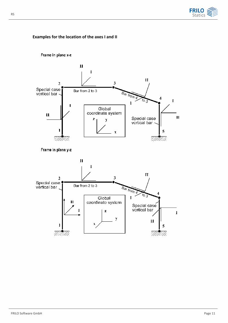
The longitudinal member axis gives orientation to the member. The arrows in the longitudinal direction of the member represent the local x-direction, which is positive when pointing from end 2 to end 2. The perpendicular arrows I and II represent the transversal member axis and the local y- and z- directions, which constitute together with the member axis a right-hand and right-angled system of coordinates. The axes I and II are main axis only with symmetrical cross sections. Axis I may be associated to the larger or smaller moment of inertia.
Directions I and II on a member in normal position (not rotated):
Member not vertical
The two transversal member directions I and II of members which are not rotated are defined automatically as follows:
Axis I lies in a plane parallel to the ground projection plane x-y. Axis II (perpendicular to the longitudinal axis and axis I) lies consequently in a vertical plane in such a position that its global z-component is always positive. Through this, also the positive direction of axis I is defined.
Vertical member:
For a strictly vertical member, the afore-mentioned definition is no longer unambiguous. Therefore, the following rule applies to this case: Axis I always points in the positive y-direction.
Directions I, II on a rotated member:
Members that are not in their normal position ( page 21) must be integrated into the system with the help of a rotation around their longitudinal axis. The rotation angle may have a size of up to +/- 360° and is positive if the rotation is clockwise from end 1 to end 2. The local I-II system of coordinates is first determined for the unrotated member and then rotated by the respective angle of rotation.
Note: You can optionally select whether the z-axis should run from bottom to top or the other way round.
Note: Several functions are available to check the position of the cross section and the local axes. They are accessible via buttons such as those shown below.
, ,
��
��
��
��
����
��
��
�
�
��
�
��
��
����
�
��
�
�
�
�
�
�
��
��
�
�
RS
FRILO Software GmbH Page 11
Examples for the location of the axes I and II

Three-dimensional frame
Page 12 Software for structural calculation and design
Pinned joints, truss members As a standard, the members are connected at the nodes with rigid joints.
You can enable any degree of freedom in the member definition section, however.
Truss members are connected with pinned joints on both ends. They are defined as truss members during their definition or when entering their properties.
Cross sections, stiffnesses By assigning a cross section to each end of the member, you define the physical properties of this member. When defining the cross sections, all values are entered that are needed for the calculation and the design.
For reasons of simplification, the shear centre is assumed to coincide with the centre of gravity.
The cross sections between the front end and rear end of the member can be constant or linearly variable. The linear modification of haunched members depends on the way the member was defined:
If the dimensions of the cross section are specified by the user or defined by selection of a shape from the F+L profile selection file, theses values are linearly interpolated. They are used to determine the cross-sectional properties A and I. To ensure a correct interpolation you should select the same type of cross section (e.g. IPE shapes) for the front and rear end of the member.
If the properties A and I are specified by the user, these values are linearly interpolated.
For rectangular cross sections with variable heights, the interpolation produces the correct parabolic characteristic in the first case and a linear and therefore incorrect characteristic in the second case. With a variable height and a constant width, a linear characteristic results in both cases.
Where haunched members with asymmetrical cross sections are concerned (e.g. L-shapes), the mean value is taken into account in the calculation of the stiffnesses for the torsional rotation of the main axes, i.e. the modification of the main axis position over the member length is not considered. To achieve more accurate results you should divide the haunch in several individual members.
In order to obtain particular physical effects, you can manipulate cross-sectional properties in view of the desired effect. It must always be ensured, however, that there is a stiffness for each of the 6 degrees of freedom at a node. Setting I=0 to disable bending stiffness is treated as a special case in the software. Members with such a cross section are automatically defined as truss members. You can practically eliminate the influence of axial force deformation by defining a large cross-sectional area.
Elastically bedded members
For continuously elastically bedded members ( page 22) the subgrade reaction modulus method is used. The bedding is assumed to act perpendicularly to the member axis. As with the cross sections, the bedding can be constant or vary linearly between the nodes. Unlike the elastic stiffness of the unbedded member, the bedding stiffness is obtained by approximation as with finite elements. The accuracy depends on the member segmentation ( page 23).
The bedding provides also support against the ground and can therefore replace supports by nodes partly or completely.
Failure of elastic bedding If elastic bedding was defined, the software considers compressive as well as tensile bedding in the calculation. If bedding is provided by elastic subsoil, tension cannot be borne under normal conditions. This effect is not automatically considered in the software. You can handle these cases by freeing particular members in one or several calculation runs from bedding, which mainly counteracts tension.

RS
FRILO Software GmbH Page 13
Calculation method General calculation method The implemented calculation is based on the displacement method with three node shifts and three torsional node rotations as system unknowns (i.e. 6 degrees of freedom per node).
The number of degrees of freedom existing in the system results to
nf = 6 nc
If only truss members are connected to a node. There is no rotational degree of freedom in this point and the number of degrees is reduced to three.
Note: Warping torsion is not considered in the frame.
Second-order analysis Basis of the non-linear second-order analysis is the displacement method as well. In this calculation, elastic stiffness is supplemented by the so-called geometrical stiffness which takes the equilibrium of the individual member in the deformed state into account.
The displacements shall remain low in relation to the system dimensions as it is typical for most buildings and other civil engineering structures. As these displacements have an influence on the load-bearing behaviour, the actual cross-sectional properties and material constants must be included in the calculation.
In systems where the axial forces and cross-sectional properties remain constant in the loaded state and are not redistributed in the deformed system, the deformations and internal forces are obtained directly without iteration. In systems, where the axial forces change in the deformed state, the internal forces and deformations must be calculated by iteration. This applies normally to general frame systems. This iteration is performed automatically by the software until a specified accuracy is obtained.
If the cross-sectional properties A and particularly I change with the deformations, stiffness must be calculated by iteration too. This applies to reinforced concrete frames for instance. In this case, the effective stiffnesses depend on the internal forces and the selected reinforcement. Each iteration step would produce new cross-sectional properties. This iteration of the cross-sectional properties is not implemented in the software. If you want to verify the buckling safety of reinforced concrete frame systems , you can do this in certain limits by reducing the bending stiffnesses ( see page 55). In addition, you must take sway imperfections into account.
Second-order calculations require higher care not only when defining the system. The engineer must also check the results carefully for plausibility.
If the buckling load of the system is exceeded, the message "Instable system" is displayed. In this case, the stiffnesses are probably too low and/or the loads too high.
The automatic max/min superposition is not available for 2nd-order analyses (max/min superpos. from 1st-o. lc), because the results of the single load cases are superimposed.
The second-order analysis is not sufficient if the torsional buckling resistance should be verified.
You should always include the displacements in the output of the results.

Three-dimensional frame
Page 14 Software for structural calculation and design
Plastic hinge method The plastic hinge method assumes ideal elastic / ideal plastic stress-strain behaviour of the material. The moment loading on a cross section can be increased until the fully plastic state is attained.
If the loading is further increased, the internal moment remains constant at the value of the plastic moment. A kink is produced at this point in the bending line, however, which is called "plastic hinge" and associated to a moment redistribution.. The loading can be increased until so many plastic hinges occur that a mechanism is created and the calculation is aborted.
Eurocode
The plastic frame calculation of load-bearing steel structures in accordance with the plastic hinge method is not implemented for EN3.
DIN 18800
The plastic frame calculation based on the plastic hinge method in accordance with DIN 18800 (plastic-plastic) is available in the software.
The interaction of all plastic internal forces of a cross section Mpl, Qpl and Npl can reduce the effective plastic moment Mpl. For double-symmetrical I shapes, the interaction is taken into account by the software. In all other cases, the software only takes the specified or internally calculated Mpl into account without consideration of Npl and Qpl. The applicability must be checked in each individual case.
The plastic internal forces are always characteristic values in the software. Therefore, the material coefficients must always be assigned to the load side in the plastic-plastic verification.
The calculation can be a first-order or second-order analysis.
Member failure You can define that individual members bear only tensile forces, compressive forces or a specified axial limit force. These specifications must be made when defining the structural system. In the output, you can select for each individual load case and/or each pre-set superposition whether the failure of the member should be examined and if so, whether in a first-order or second-order analysis. The truss members as well as members connected rigidly in the system are completely dispensed with in the examination of member failure. If members fail that are relevant for the load-bearing behaviour in such a manner that a mechanism is created, the calculation is aborted. Note: Members under temperature load cannot be included in the examination of member
failure.
Buckling load/effective lengths For individual load cases and pre-set superpositions, you can calculate the buckling load referenced to the total system in accordance with the theory of elasticity (i.e. without consideration of plasticities).
The buckling load factor ki (eta ki in the software) calculated in the software always refers to the first eigenvalue found. You should note that the calculated values such as the effective length or the slenderness ratio are only valid if the bending line under load is similar to the buckling pattern and ki is greater than 1.
In the calculation of the buckling load, member failure is not examined, i.e. all members are included in the calculation.
The calculated values such as the effective lengths can currently not be used for advanced verifications.
RS
FRILO Software GmbH Page 15
Definition of the system
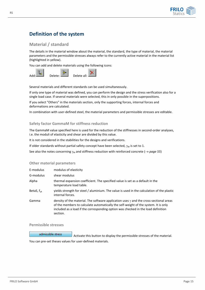
Material / standard The details in the material window about the material, the standard, the type of material, the material parameters and the permissible stresses always refer to the currently active material in the material list (highlighted in yellow).
You can add and delete materials using the following icons:
Add: Delete: Delete all:
Several materials and different standards can be used simultaneously.
If only one type of material was defined, you can perform the design and the stress verification also for a single load case. If several materials were selected, this in only possible in the superpositions.
If you select "Others" in the materials section, only the supporting forces, internal forces and deformations are calculated.
In combination with user-defined steel, the material parameters and permissible stresses are editable.
Safety factor GammaM for stiffness reduction The GammaM value specified here is used for the reduction of the stiffnesses in second-order analyses, i.e. the moduli of elasticity and shear are divided by this value.
It is not considered in the stabilities for the designs and verifications.
If older standards without partial safety concept have been selected, M is set to 1.
See also the notes concerning M and stiffness reduction with reinforced concrete ( page 55)
Other material parameters E-modulus modulus of elasticity
G-modulus shear modulus
Alpha thermal expansion coefficient. The specified value is set as a default in the temperature load table.
BetaS, fyk yields strength for steel / aluminium. The value is used in the calculation of the plastic internal forces.
Gamma density of the material. The software application uses and the cross-sectional areas of the members to calculate automatically the self-weight of the system. It is only included as a load if the corresponding option was checked in the load definition section.
Permissible stresses
Activate this button to display the permissible stresses of the material.
You can pre-set theses values for user-defined materials.
Three-dimensional frame
Page 16 Software for structural calculation and design
Cross sections Depending on the selected material, the following options are available to define a cross section:
F + L profile selection file ( page 18)
Steel cross-section dimensions ( page 18)
Concrete/timber cross-section dimensions ( page 19)
Structural cross-sectional properties – I, A, W ( page 19)
Importing values from the Frilo applications Q2 and Q3 ( see page 21)
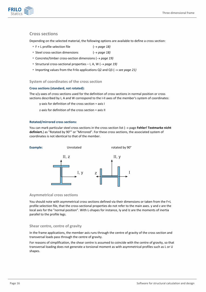
System of coordinates of the cross section Cross sections (standard, not rotated):
The x/y-axes of cross sections used for the definition of cross sections in normal position or cross sections described by I, A and W correspond to the I-II axes of the member's system of coordinates:
y-axis for definition of the cross section = axis I
z-axis for definition of the cross section = axis II
Rotated/mirrored cross sections:
You can mark particular steel cross sections in the cross section list ( page Fehler! Textmarke nicht definiert.) as "Rotated by 90°" or "Mirrored". For these cross sections, the associated system of coordinates is not identical to that of the member.
Example: Unrotated rotated by 90°
Asymmetrical cross sections You should note with asymmetrical cross sections defined via their dimensions or taken from the F+L profile selection file, that the cross-sectional properties do not refer to the main axes. y and z are the local axis for the "normal position". With L-shapes for instance, Iy and Iz are the moments of inertia parallel to the profile legs.
Shear centre, centre of gravity In the frame applications, the member axis runs through the centre of gravity of the cross section and transversal loads pass through the centre of gravity.
For reasons of simplification, the shear centre is assumed to coincide with the centre of gravity, so that transversal loading does not generate a torsional moment as with asymmetrical profiles such as L or U shapes.
�����
����
�����
��

RS
FRILO Software GmbH Page 17
Cross section list
The list displays the defined cross sections in the form of a table. A consecutive number (first column) is assigned to each cross section. The assignment of the cross section numbers to the respective members is done in the member definition section.
To add a new cross section, either press the "Insert" button to the right of the table and the <F5> key or double-click in the empty row below the last entry. Description of the buttons
You can see three buttons in the upper area of the window that access three different tables:
Define profile accesses the table to define a profile.
Profile details displays a table with additional information about the listed cross sections as long as you activate the button.
Plast. moments displays the values of the plastic internal forces. You can find further information in the chapter "Plastic hinges" ( pages 14, 23 ).
Description of the profile definition table
Number L-, U-, I- and square tube shapes can be arranged as simple, double or triple profiles next to each other. The stiffnesses are added up linearly in the calculation. Two shapes next to each other are treated in principle as if two members with the corresponding section would lie next to each other and bear half of the load each. The influence of shapes welded together is not considered.
Material specification of the material number that should be assigned to the cross section.
Rotate by 90° rotates L-, U-. I- and square tube shapes by 90°. The cross-sectional properties and the plastic moments are shown for the rotated cross section, see also cross section position ( page 21).
Note: When entering the dimensions, the corresponding cross section is shown in the unrotated state in the associated window.
Mirror mirrors L-shapes.
Plate only enabled for reinforced concrete: shear design as a plate (without relevance in RS)
Bedding specification of the subgrade reaction modulus for elastically bedded members ( page 22). Please observe the dimensional unit [kN/cm²].
Bedding II bedding in direction of member axis II. Bedding I bedding in direction of member axis I.
Ill.: Cross section list
You can edit a cross section by either pressing the <F5> key or double clicking with the left mouse button or single clicking with the right mouse button in the Name column.
Three-dimensional frame
Page 18 Software for structural calculation and design
F + L profile selection file Various rolled shapes are stored in this file. Make sure that the selected shape is available on the market. Shapes that are no longer available are not removed from the database to allow as-built calculations with former shapes.
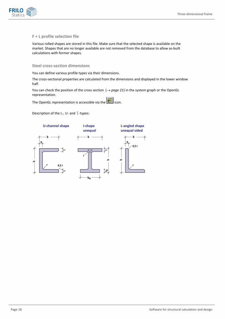
Steel cross-section dimensions You can define various profile types via their dimensions.
The cross-sectional properties are calculated from the dimensions and displayed in the lower window half.
You can check the position of the cross section ( page 21) in the system graph or the OpenGL representation.
The OpenGL representation is accessible via the icon.
Description of the L-, U- and I-types:
U-channel shape I-shape L-angled shape unequal unequal sided

RS
FRILO Software GmbH Page 19
Concrete/timber cross-section dimensions You can select among the following types:
Rectangle T-beam T-beam reversed I-beam Solid circle Annulus
��
�� ���
�
��
��
��
��
��
��
��
� ��
� ��
��
� ��
��
��
��
�� � ��
Factor for stiffness reduction
In addition to the definition of the geometric cross-sectional dimensions, you can specify a factor by which the moments of inertia should be multiplied (in ESK, only the factor for ly is used).
This factor allows you to consider the relation of the stiffnesses in state I to the effective stiffnesses in state II over the member length by approximation. If the effective stiffnesses are based on the failure state, the total system can be verified in a second-order analysis. For additional information about stiffness reduction with reinforced concrete see page 55.
Reinforcement layers
If the selected material is concrete, you are prompted to define the reinforcement layers at d1 and d2. d1 and d2 represent the distance of the reinforcement's gravity line to the edges.
d1: distance on the side of the negative axis II section. d2: distance on the side of the positive axis II section.
Cross sectional properties I, A, W You are prompted to specify the values manually. For standard shapes, we recommend defining the cross section via its dimensions or by selecting a shape from the F+L profile selection file. Input fields
The definition options are based on the system of coordinates of the cross section ( page 16). Values for the structural calculation
Iy, Iz second-order moment of area. For asymmetrical cross sections see comments below.
It second-order torsional moment of area
A cross sectional area
Aqy,z shear area for the stiffness calculation
Three-dimensional frame
Page 20 Software for structural calculation and design
Values for the stress calculation:
Wy ob resistance moment on top
Wy un resistance moment on bottom
Wz li resistance moment on the left
Wz re resistance moment on the right
Wt torsion resistance
ATy,z shear area for the simplified shear stress resistance verification
Value for thermal calculations and the graphical representation:
Width width in y-direction
Height height in z-direction
Required specifications
The values to be specified depend on the software application and the selected verification. The window was conceived for a comparison of the data in different software applications.
Software Values used
ESK Iy, Iyz, Iz A, Aqz, Wy ob, Wy un, ATz, height, width
RS Iy, Iyz, Iz, A, Aqy, Aqz, Wy ob, Wy un, Wz li, Wz re, Wt, ATy, ATz, height, width
TRK Iy, Iyz, Iz, It, A, Aqz, Wy ob, Wy un, Wt, ATz, height, width
DLT10 Iy, Iyz, Iz, A, Aqy, Aqz, Wy ob, Wy un, ATy, ATz, height, width
Comments
Enter positive values for the resistance moments.
In order to obtain particular physical effects, you can manipulate cross-sectional properties in view of the desired effect.
You need to define a shear area if deformations by shear should be considered. The shear area of typical shapes can be taken from expert literature. For solid rectangular cross sections it is determined by the following expression Aq = A 5/6. For less compact profiles such as T, I, hollow box and circle, it may fall considerably below A. The shear area of a thin-walled round pipe section, for instance, is Aq = A/2.
ATy,z is the area to which the following applies: TauQ = Q / ATy,z. It is only used when shear stresses should be calculated.
Note: When you define a cross section by specifying its dimensions or selecting it from the F+L profile selection file, the cross section characteristic is known. TauQ is calculated as follows in these cases:
QQ SI b
The height and the width are required to calculate a temperature load case. Moreover, they are used for the graphical representation of the cross section.
If stresses should be calculated, you must specify the decisive resistance moments or shear areas.
RS
FRILO Software GmbH Page 21
Import cross sections from the Q2 and Q3 applications This option allows you to import cross-sectional properties that have been generated with the F+L applications Q2 or Q3 into the frame.
The cross section calculation software does not determine all required cross-sectional properties, however. Q2 does not determine torsion values for instance. Therefore, you should check whether all cross sectional properties required for the system are available. You should add missing values in the I, A, W window (see previous chapter).
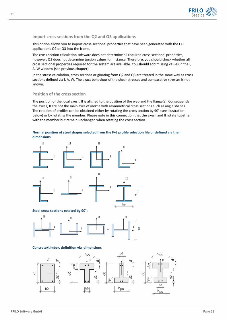
In the stress calculation, cross sections originating from Q2 and Q3 are treated in the same way as cross sections defined via I, A, W. The exact behaviour of the shear stresses and comparative stresses is not known. Position of the cross section The position of the local axes I, II is aligned to the position of the web and the flange(s). Consequently, the axes I, II are not the main axes of inertia with asymmetrical cross sections such as angle shapes. The rotation of profiles can be obtained either by rotating the cross section by 90° (see illustration below) or by rotating the member. Please note in this connection that the axes I and II rotate together with the member but remain unchanged when rotating the cross section.
Normal position of steel shapes selected from the F+L profile selection file or defined via their dimensions
��
�
��
�
��
�
��
�
��
�
��
�
��
�
��
�
��
Steel cross sections rotated by 90°:
��
��
�
��
�
��
�
��
�
Concrete/timber, definition via dimensions
��
�� ���
�
��
��
��
��
��
��
��
� ��
� ��
��
� ��
��
��
��
��
� ��
�
��
�
��
�
��
�
��

Three-dimensional frame
Page 22 Software for structural calculation and design
Elastic bedding The software handles elastic bedding in accordance with the subgrade reaction modulus method.
Bedding can act in the direction of the member axes I and/or II. You can enter it in the cross section definition window ( page 17).
If only a single cross section was defined for all members in the system but only a part of the members is bedded elastically, you should define the same cross section twice, one with and the other without subgrade modulus.
If a member should be bedded elastically you must assign the corresponding cross section when defining this member. The bedding between the nodes can be constant (same cross section at the front end (1) and rear end (2) of the member) or linearly variable (different cross sections).
In the cross section table, you must enter the value of the subgrade reaction modulus kb multiplied by the beam width. The value to define has the dimension of force/area! It must always be specified in [kN/cm²]. Input value = subgrade reaction modulus beam width [kN/cm²] The value is 0.00 for cross sections without elastic bedding.
HAHN1 provides an orientation for the subgrade reaction modulus method kb (in [kN/cm³]!):
Clay soil, wet 0.02 ... 0.03 kN/cm³ Clay soil, dry 0.06 ... 0.08 kN/cm³ Fine gravelly sand soil 0.08 ... 0.10 kN/cm³ Coarse gravelly sand soil 0.15 ... 0.20 kN/cm³ Example: Dry clay soil, beam width of 40 cm: Value entered in table = 0.07 40 = 2.8 kN/cm²
If the modulus of compressibility Es is known (e.g. given by the soil expert), it must be converted into the subgrade reaction modulus kb, which depends on the shape and dimensions of the bedded component. There are several approaches in expert literature to the area to be used in the conversion. HAHN1 [p. 283] specifies the following formula for rectangular areas:
sb 2
Ek(1 )bV◊=-n
is a coefficient for the area shape of the foundation via the relation of the length to the width l/b:
l/b
1.00
1.05
1.50
0.87
2.00
0.78
3.00
0.66
5.00
0.54
10.00
0.45
20.00
0.39
30.00
0.33
50.00
0.30

RS
FRILO Software GmbH Page 23
is the transverse expansion coefficient of the soil: for sand/gravel: = 0.125 ... 0.5 for clay: = 0.2 ... 0.4 Betonkalender 1998, part 2, p. 472 specifies guiding values for the modulus of compressibility:
Pure gravel 10.00 ... 20.00 Pure sand 1.00 ... 10.00 Coarse clay 0.30 ... 1.50 Clay 0.10 ... 6.00 Peat 0.01 ... 0.10 1 HAHN, J.: Durchlaufträger, Rahmen, Platten und Balken auf elastischer Bettung. 13th edition, Düsseldorf (Werner) 1981.
Elastic length Unlike the elastic stiffness of the unbedded member, the bedding stiffness is obtained by approximation as with finite elements. The accuracy depends on the member segmentation. If the member length is too high, completely useless results might be produced. The stiffer the bedding the finer should be the member segmentation. The elastic length serves as a guiding value:
4Bettung
4EILe
K=
With constant bedding, the member length should be
L < 1.5 Le
and with linearly variable bedding, it should be
L < 0.75 Le.
Plastic internal forces If you activate the "plast. moments" button in the cross section definition dialog, the characteristic values of the plastic internal forces of the existing cross sections are displayed:
Mpl,y, Mpl,z plastic moments of the cross section
Npl axial force in the plastic state
Qpl,z, Qpl,y shear forces in the plastic state
The software application calculates the plastic internal forces for cross sections that have not been defined via A, I, W. These values cannot be edited. User-defined Mpl values are only considered for the cross sections that have been defined via A, I, W.
The plastic internal forces are calculated using the value for
ßs (= fyk = characteristic value of the yield strength) specified in the material selection window.
You can find further information in the bases of calculation of the plastic hinge method ( page 14) and in the presentation of the results of the plastic hinge calculation ( page 53).
Three-dimensional frame
Page 24 Software for structural calculation and design
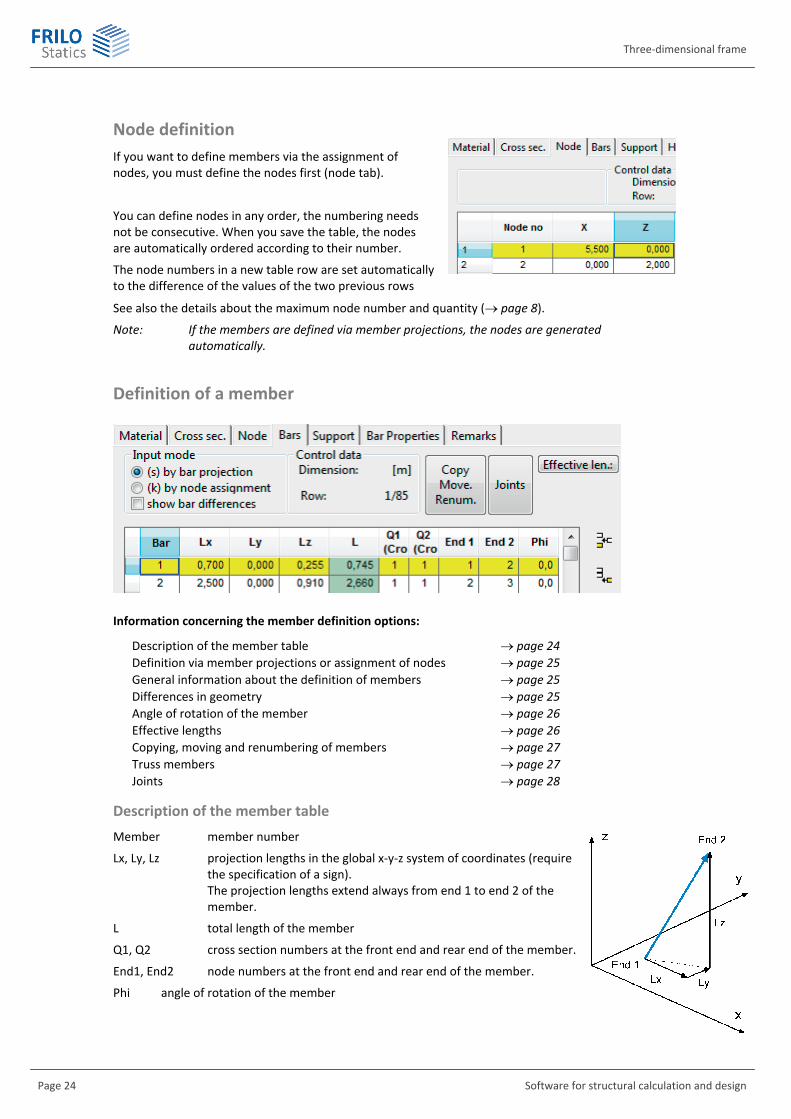
Node definition If you want to define members via the assignment of nodes, you must define the nodes first (node tab).
You can define nodes in any order, the numbering needs not be consecutive. When you save the table, the nodes are automatically ordered according to their number.
The node numbers in a new table row are set automatically to the difference of the values of the two previous rows
See also the details about the maximum node number and quantity ( page 8).
Note: If the members are defined via member projections, the nodes are generated automatically.
Definition of a member
Information concerning the member definition options:
Description of the member table page 24 Definition via member projections or assignment of nodes page 25 General information about the definition of members page 25 Differences in geometry page 25 Angle of rotation of the member page 26 Effective lengths page 26 Copying, moving and renumbering of members page 27 Truss members page 27 Joints page 28
Description of the member table Member member number
Lx, Ly, Lz projection lengths in the global x-y-z system of coordinates (require the specification of a sign).
The projection lengths extend always from end 1 to end 2 of the member.
L total length of the member
Q1, Q2 cross section numbers at the front end and rear end of the member.
End1, End2 node numbers at the front end and rear end of the member.
Phi angle of rotation of the member

RS
FRILO Software GmbH Page 25
Definition via member projections or the assignment of nodes First, select first the definition mode, i.e. whether to define the members via their projection lengths or the coordinates of the associated nodes.
Definition via member projections
If the members are defined via member projections, the nodes are generated automatically.
Among other things, you must specify the projection length as well as the node number at the front end (1) and rear end (2).
The zero point of the system of coordinates of the total structural system is automatically assumed in the left lower corner to make sure that the node coordinates calculated by the software application have always positive values.
Definition via assignment of nodes
Unlike the definition via projections, the definition via the assignment of nodes requires that you have defined nodes before. You cannot enter projection lengths. They are calculated from the node coordinates. The node number in a new table row is automatically incremented by the difference of the numbers of the two previous rows.
General information about the definition of members
See the details about the maximum node number and quantity ( page 8).
You can number the members in any order.
A prerequisite to the description of the member is the previous definition of cross sections.
The members run through the cross sections’ centres of gravity.
Members with a length L=0 are not permissible.
The differences in stiffness EA/L or EI/L³ of the members that are connected in a node must not be too great because this might produce incorrect results.
If the cross section of a member was defined with elastic bedding, the software checks whether the member length exceeds the elastic length during the definition process. In case of inconsistent specifications, a warning message is displayed and you must subdivide the member to ensure correct results.
When you delete a member, the loads referring to this member are deleted too.
When you edit member properties (e.g. the member length) you must check the referring load in regard to possible changes.
Differences in geometry In many cases, the definition of the system via member projections is faster than the definition via node assignment which requires the previous definition of nodes.
The definition of members via projections involves the risk of differences in the system, however. Existing differences are displayed in the member definition section as well as in the output of system data via tables.
You should avoid differences is the system as far as possible, because the member stiffnesses are calculated from the projection lengths and differences might produce incorrect stiffness values. High differences might even produce completely incorrect results.
Three-dimensional frame
Page 26 Software for structural calculation and design
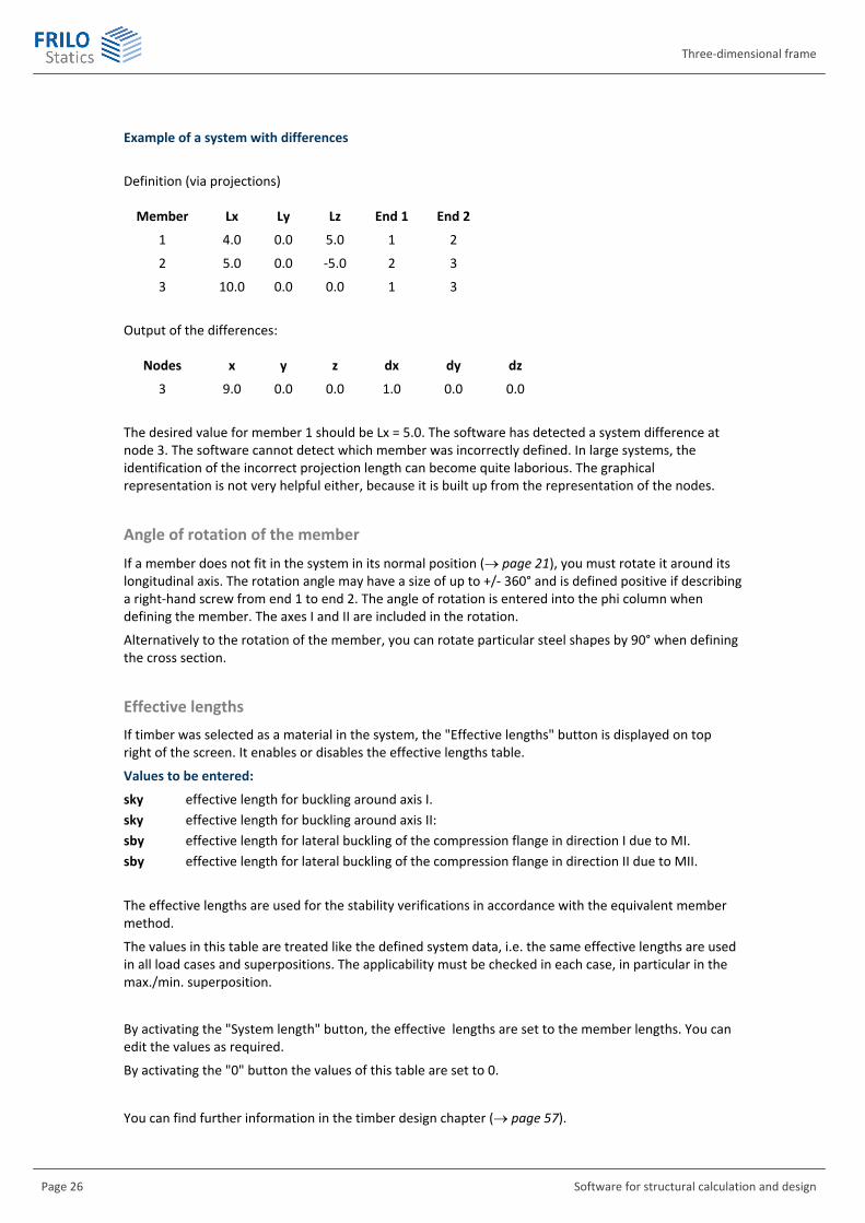
Example of a system with differences
Definition (via projections)
Member Lx Ly Lz End 1 End 2
1 4.0 0.0 5.0 1 2
2 5.0 0.0 -5.0 2 3
3 10.0 0.0 0.0 1 3
Output of the differences:
Nodes x y z dx dy dz
3 9.0 0.0 0.0 1.0 0.0 0.0
The desired value for member 1 should be Lx = 5.0. The software has detected a system difference at node 3. The software cannot detect which member was incorrectly defined. In large systems, the identification of the incorrect projection length can become quite laborious. The graphical representation is not very helpful either, because it is built up from the representation of the nodes.
Angle of rotation of the member
If a member does not fit in the system in its normal position ( page 21), you must rotate it around its longitudinal axis. The rotation angle may have a size of up to +/- 360° and is defined positive if describing a right-hand screw from end 1 to end 2. The angle of rotation is entered into the phi column when defining the member. The axes I and II are included in the rotation.
Alternatively to the rotation of the member, you can rotate particular steel shapes by 90° when defining the cross section.
Effective lengths If timber was selected as a material in the system, the "Effective lengths" button is displayed on top right of the screen. It enables or disables the effective lengths table.
Values to be entered:
sky effective length for buckling around axis I. sky effective length for buckling around axis II: sby effective length for lateral buckling of the compression flange in direction I due to MI. sby effective length for lateral buckling of the compression flange in direction II due to MII.
The effective lengths are used for the stability verifications in accordance with the equivalent member method.
The values in this table are treated like the defined system data, i.e. the same effective lengths are used in all load cases and superpositions. The applicability must be checked in each case, in particular in the max./min. superposition.
By activating the "System length" button, the effective lengths are set to the member lengths. You can edit the values as required.
By activating the "0" button the values of this table are set to 0.
You can find further information in the timber design chapter ( page 57).

RS
FRILO Software GmbH Page 27
Effective lengths calculated by the software
Optionally, the software calculates the effective lengths in the frame plane for each load case (check the "EtaKi" option in the output control for single load cases and pre-set superpositions, page 52).
The calculated effective lengths are not connected logically to the values specified in the effective length table.
Copying, moving and renumbering members This dialog allows you to copy, renumber or move the currently selected members.
You can generate the new member and node numbers either with a number offset (recommended) or by specifying the start number and the increment. The selection of rows is done in accordance with the Windows standard:
Selection of a block of rows:
Click with the left mouse button in the grey cell at the left border of the table (left to the "member" column) to select the first row of the block.
Keep the <Shift >key pressed and click in the grey cell in the last row of the block. All rows in-between are selected.
Alternatively, you can move the mouse over the left table border (left to the "member" column) with the left mouse key pressed to select the desired block.
Selection of several individual rows:
You can select several rows that are not one below the other by pressing the Ctrl key and clicking in the corresponding grey cells at the left table border.
Truss members Truss members are those members that cannot transfer moments at their nodes. In a truss member not subjected to external loads, only the axial force acts as an internal force. You have the following three possibilities to generate members with this property: 1. Marking members as truss members
You can assign the truss member property in the member definition section ("FW/Joints" column) or in the member properties menu ( page 31). For truss members, only the internal forces at the front end of the member are put out, i. e. further member segmentation is not available.
Note: You cannot define additional pinned joints for members marked as truss members. 2. Defining joints
When defining a member, you can obtain the effect of a truss member (FW/Joints button) by inserting a moment joints at both ends. You must specify the following in the joint table:
MI/QII MI/QII MII/QI MII/QI N End 1 End 2 End 1 End 2 Torsion
1 1 1 1 2
The definition of pinned joints involves more work than the simple marking of a member as a truss member. The definition via pinned joints allows further member segmentation. Moreover, all internal forces are put out for pinned members, not only the axial force. If the members are subjected to loads e.g. by self-weight, we recommend defining truss members via pinned joints.
Note: Members with pinned joints cannot be marked as truss members in addition.

Three-dimensional frame
Page 28 Software for structural calculation and design
3. Setting I = 0
Another way is to set the moments of inertia Iy and lz to zero when defining the cross section (see Defining cross sections via I, A, W, page 19). The property “truss member” is automatically assigned to the member, which is treated as described above.
Note: The truss member assignment is not automatically undone when you define a moment of inertia subsequently.
Joints To define joints, click in the member definition section ( page 24) on the "FW/Joints" button. A window is displayed that allows you to enter a truss member or a pinned joint.
You can define torsion, moment, shear force and axial force joints referenced to the local member axis for each member. The type of joint is defined by an identification code. The codes are explained in the status line below the table.
Moments/shear forces Axial force/torsion
0 = rigid for moments and shear force 1 = moment joint 2 = shear force joint 3 = moment and shear force
0 = rigid for axial force and torsion 1 = axial force joint 2 = torsion joint 3 = axial force and torsion joint
Note:
There must be a stiffness for each of the 6 degrees of freedom at each node. If two members should be connected in a pinned joint, you must assign the joint only to one of the two members, otherwise instability occurs. This applies also to the supports. A joint is defined either at the support or at the member; both cannot be done (double function).
A member can either have pinned joints or be defined as a truss member; you cannot do both at a time.
You can connect truss members as well as members with pinned joints in the same node. Also in this case, at least one stiffness must have been defined for each of the six degrees of freedom.

RS
FRILO Software GmbH Page 29
Supports You can assign supporting conditions to each node in accordance with the three node displacements in the x, y and z directions and the three torsional node rotations. Each of the three supporting conditions can either be rigid, elastic or free.
Rigid support
Specifying "-1.0" defines a rigid support in the corresponding direction "x, y, z, aroundx, aroundy, aroundz". Internally, a rigid support is simulated by a spring with a high stiffness.
Note: When specifying "-6" in the "x-direct." column, the values in the next six columns are set to "-1.0".
When specifying "-3" in the "x-direct." column, the values in the next three columns are set to "-1.0".
Free support
The specification of "0.0" defines a free support in the corresponding direction.
Elastic support
Elastic support is defined by specifying a spring stiffness in the corresponding column. The spring stiffnesses must be specified with the following units:
Axial force spring: [kN/cm]
Torsional spring: [kN cm / rad]
Note: You can use exponents to specify very high spring values (e.g.: 1.3e10).
Supporting direction Activating the button "rotated supports" displays or hides the additional columns "Vec x", "Vec z" and "Vec z", which allow you to specify the support's direction of action.
Standard case: unrotated support
The default setting "0.0" defines an unrotated support; the settings for "x, y, z, aroundx, aroundy, aroundz" refer to the global system of coordinates.

Three-dimensional frame
Page 30 Software for structural calculation and design
Rotated support
A local system of coordinates for the support is generated via the vector that results when adding "Vec x", "Vec y" and "Vec z". It represents the x-axis of the local system of coordinates. The specification of the fixed supports in the columns "x, y, z, aroundx, aroundy, aroundz" refer to this local system of coordinates.
The local system of coordinates of the support is defined in the same way as the local system of coordinates of the member ( page 10). Consequently, the following applies to the support directions:
x indicates the direction of the resulting vector.
z is perpendicular to the resulting vector x in a vertical plane in such a manner that the global z-components are always positive (analogous to axis II defined for the member).
y is perpendicular to x and z and lies in a plane that is parallel to the global x-y plane (analogous to axis I defined for the member).
The special case of a vertical resulting vector is not relevant in practice. The assignment shown above does not apply to this special case.
Example of a rotated support
Definition of a support at node 1:
Node no. x-direct. y-direct. z-direct. around
x around y
around z
Vec x Vec y Vec z
1 -1 0 0 0 0 0 -1.0 0.0 2.0

RS
FRILO Software GmbH Page 31
Member properties In the member properties menu, you can do the following:
Define tension and compression members
Set members active / inactive
Define truss members
Enter axial force springs
Enter the system length of members
Failure mode
The "Failure mode" column allows you to specify whether members should fail under tension or compression.
Definition options:
0 or "empty field" the member can bear all existing tension and compression forces. D the member fails under compressive force. Z the member fails under tensile force. Limit load magnitude of the maximum compression or tension load the member can
bear. If the axial force is greater (under tension) or smaller (under compression) than the specified value, the member fails.
Note: As a standard, the software performs a first-order analysis without member failure. To enable member failure in the calculation, select the corresponding calculation method in the output window (or the toolbar on top), "1st order + failure" for instance.
Active
If the checkbox in the "Active" column is not checked for a member, no results are put out for this member. Internally, a very low stiffness is assumed for inactive members, so that these members do practically not exist in the system. The detection of instabilities becomes more difficult due to these small stiffnesses, however.

Three-dimensional frame
Page 32 Software for structural calculation and design
Truss member
Members with a check mark in this column behave as truss members ( page 27 ), i. e. these members are installed with pinned connections in the system. You can define truss members also in the member table.
Axial force spring (N-spring) at end 1, axial force spring (N-spring) at end 2
These columns allow you to define axial force springs that act at the corresponding member end in direction of the member axis. The springs have no computed length. The unit of the value to specify is always [kN/cm]
The specification of 0.0 means that no axial force spring exists.
The definition of axial force springs allows you to take the compliance of dowel connections in timber structures into account, for instance.
System length
If the buckling load factor Ki ( p. 52) of the system is calculated, the specification of a system length is required for the determination of the member identification number and the effective length factor . The default value is the member length. The default will produce nonsensical results if a hinged column is described with the help of two members.
If and are of interest, you should check the system length for plausibility particularly when applying subsequent changes to the structural system. Advanced verifications do not depend on the system length.
Texts concerning the system You can enter comments to the system and the load cases which are inserted in the output.
The entering and processing of these texts is based on the Windows standard, similar to the text editor included in the Windows OS package.

RS
FRILO Software GmbH Page 33
Load cases
The window shown above allows you to enter and edit load cases. A load case can include any number of loads. You should enter the loads with their characteristic values. The design of load cases is only available if a material was defined. The definition of load cases is a prerequisite for the definition of superpositions.
Editing load cases Icons below the load case table
These icons allow you to add a load case, delete the most recent load case (not any other one) or delete all load cases.
Note: Double clicking in the first empty row below the lowest load case sets up a new load case.
Rename load case
Click on the load case and enter a new name.
To change only parts of the existing name, click on the load case and press F2 subsequently. You can change the corresponding sections of the name.
Factor for all LC
This button allows you to divide existing load cases easily by the specified factors and assign particular actions to them. The function is useful to take over load cases based on former standards.
Take over load case
This button allows you to add the loads of any other load case to the currently active one (yellow highlighted). In the dialog displayed subsequently, you are prompted to specify a factor by which the loads to be taken over should be multiplied.
Delete all loads
The "Delete all loads" button allows you to delete all loads of the currently active (yellow highlighted) load case. The load case itself is preserved.
Three-dimensional frame
Page 34 Software for structural calculation and design
Assignment of actions In the Act.grp column, you can assign actions to the load cases.
Clicking in the column and on the arrow button displays a combo box with a selection list of actions. A more detailed representation including combination coefficients and partial safety factors is displayed when pressing F5.
This column is not displayed in combination with older standards.
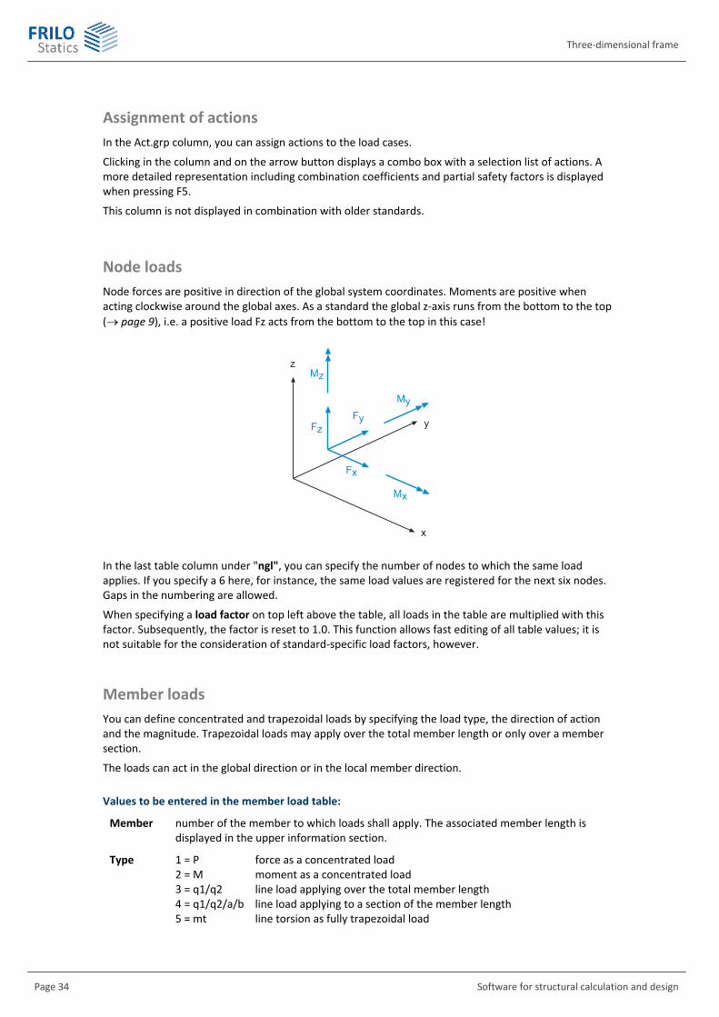
Node loads Node forces are positive in direction of the global system coordinates. Moments are positive when acting clockwise around the global axes. As a standard the global z-axis runs from the bottom to the top ( page 9), i.e. a positive load Fz acts from the bottom to the top in this case!
�
�
�
��
��
��
��
��
��
In the last table column under "ngl", you can specify the number of nodes to which the same load applies. If you specify a 6 here, for instance, the same load values are registered for the next six nodes. Gaps in the numbering are allowed.
When specifying a load factor on top left above the table, all loads in the table are multiplied with this factor. Subsequently, the factor is reset to 1.0. This function allows fast editing of all table values; it is not suitable for the consideration of standard-specific load factors, however.
Member loads You can define concentrated and trapezoidal loads by specifying the load type, the direction of action and the magnitude. Trapezoidal loads may apply over the total member length or only over a member section.
The loads can act in the global direction or in the local member direction.
Values to be entered in the member load table:
Member number of the member to which loads shall apply. The associated member length is displayed in the upper information section.
Type 1 = P force as a concentrated load 2 = M moment as a concentrated load 3 = q1/q2 line load applying over the total member length 4 = q1/q2/a/b line load applying to a section of the member length 5 = mt line torsion as fully trapezoidal load

RS
FRILO Software GmbH Page 35
Direction referenced to the projection length: 1 = global x-direction 2 = global y-direction 3 = global z-direction 4 = along the member axis, positive from end 1 to end 2 5 = cross to the member axis is direction I 6 = cross to the member axis is direction II
Referenced to the projection length: 7 = global x-direction 8 = global y-direction 9 = global z-direction
P1 for concentrated loads = load value for line loads = load ordinate at member end 1 P2 load ordinate at member end 2 (only enabled for line loads)

Three-dimensional frame
Page 36 Software for structural calculation and design
Distance distance of the load or the left load ordinate to member end 1. The distances are measured in the direction of the member axis.
Length length of line section loads. The load length is measured in the direction of the member axis.
ngl number of members to which the same type of load applies. If you specify a 6 here, for instance, the same load values are registered for the next six nodes. Gaps in the numbering are allowed.
Load factor (on top left above the table)
When specifying a load factor on top left above the table, all loads in the table are multiplied with this factor. Subsequently, the factor is reset to 1.0. This function allows fast editing of all table values; it is not suitable for the consideration of standard-specific load factors, however.
Positive direction of the local member loads
��
�
���
���
������
Temperature loads Evenly and unevenly distributed heating may apply simultaneously.
If you define unevenly distributed temperature loading, the height of the cross section must be known. If you have defined the loaded cross section via its dimensions or selected it from the F+L profile selection file, the height is automatically registered. If you have defined the cross section via the specification of A, I, W, you must enter the height in the cross section definition window.
Values to enter in the table:
Const T
Evenly distributed temperature loading is positive when it causes elongation of the member.
� ����������������������
RS
FRILO Software GmbH Page 37
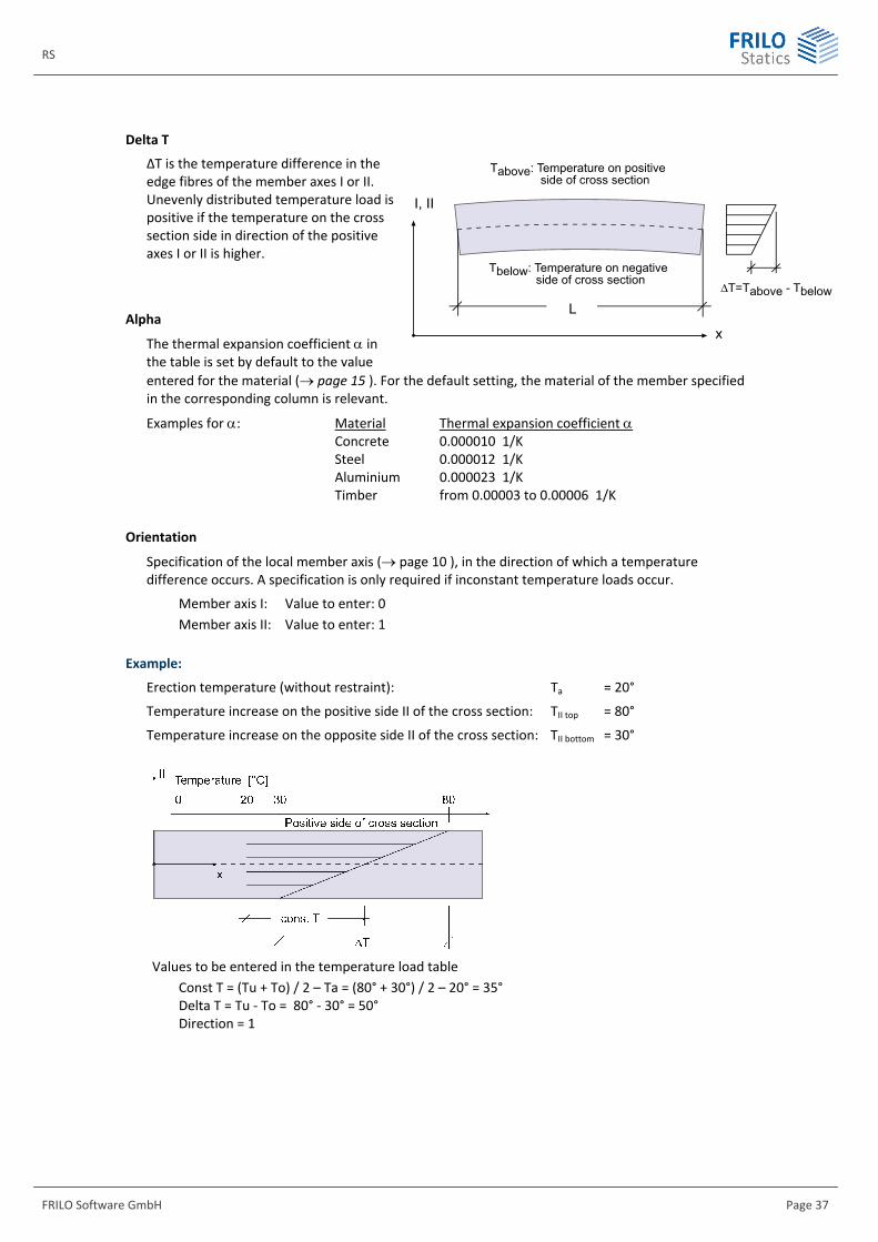
Delta T
ΔT is the temperature difference in the edge fibres of the member axes I or II. Unevenly distributed temperature load is positive if the temperature on the cross section side in direction of the positive axes I or II is higher.
Alpha
The thermal expansion coefficient in the table is set by default to the value entered for the material ( page 15 ). For the default setting, the material of the member specified in the corresponding column is relevant.
Examples for : Material Thermal expansion coefficient Concrete 0.000010 1/K Steel 0.000012 1/K Aluminium 0.000023 1/K Timber from 0.00003 to 0.00006 1/K
Orientation
Specification of the local member axis ( page 10 ), in the direction of which a temperature difference occurs. A specification is only required if inconstant temperature loads occur.
Member axis I: Value to enter: 0 Member axis II: Value to enter: 1
Example:
Erection temperature (without restraint): Ta = 20°
Temperature increase on the positive side II of the cross section: TII top = 80°
Temperature increase on the opposite side II of the cross section: TII bottom = 30°
Values to be entered in the temperature load table
Const T = (Tu + To) / 2 – Ta = (80° + 30°) / 2 – 20° = 35° Delta T = Tu - To = 80° - 30° = 50° Direction = 1
L
Tbelow: Temperature on negative side of cross section
I, II
x
ΔT=Tabove - Tbelow
Tabove: Temperature on positive side of cross section
Three-dimensional frame
Page 38 Software for structural calculation and design
Prestressing Prestressing is currently not available.
Support deformation You can define support displacement and torsional rotation only on rigidly supported nodes. A prerequisite to this is that "-1" was specified for the corresponding direction in the support definition section ( page 29).
The deformation direction depends on the definition of the support. If the support is rotated, the deformations refer to the rotated (local) system of coordinates.
The displacements fx, fy, fz are positive if they act in the direction of the coordinate axes.
The unit of the defined deformation is always [cm] even if the system was defined in [m].
The directions of rotation Phix, Phiy and Phiz are positive if they act clockwise around the corresponding axis.
Torsional support rotation is specified with a circular measure: Torsional rotation [rad] = torsional rotation [Grad] / 180°
Self-weight You must define in the load definition window whether self-weight should be taken into account in the calculation.
The software calculates the self-weight automatically from the material density and the member dimensions (with a gravitational force of g = 10.0 m/s²).
The load that applies is the self-weight of the members multiplied with the factor specified in the self-weight window (positive, if acting in the direction of the global coordinate axes).
If the positive z-axis runs to the top, the following applies:
Factor x = 0.0
Factor y = 0.0
Factor z = -1.0
Sway imperfection Sway imperfection is only available in the plain frame.
Gamma for second-order analyses Load factor for second-order analyses, used in combination with older standards with a global safety concept.
Permissible Sigma In combination with older standards, permissible stresses can be assigned to the load cases in the load definition window.
RS
FRILO Software GmbH Page 39
Superposition
Pre-set superposition If pre-set superpositions are used, load cases are combined according to fixed rules, i.e. the software application does not examine whether a load case has a favourable or unfavourable effect.
You can apply the same calculation methods as to single load cases (e.g. first-order analysis, second-order analysis, member failure, etc.).
When you use pre-set superpositions, the loads are multiplied internally with the specified factors and added up. Subsequently, they are treated like a single load case.
All results such as support reactions, internal forces, design values and displacements are influenced by factors.
The table on the left lists all existing superpositions and you can define new superpositions or delete existing ones. Always only the most recently defined superposition is available for deletion.
The table on the right allows you to define the associated superposition rules.
Under normal conditions, the option "Act.grp" is checked in the left table. Two columns for each superposition are displayed in the right table. In the "Active" column, you check all load cases that take part in the superposition. In the "Lead" column, you define the leading action as well as the partial safety factor for permanent actions. You can edit the factor by clicking in the corresponding field. The partial safety factors and combination coefficients are set automatically by the software. If no particular leading action was defined, all active load cases are treated as leading action.
Tip: By clicking in the grey "Act.grp." cell you can check or uncheck all checkboxes at a time. By clicking in the grey "Active" cell you can enable or disable all load cases at a time.
When you uncheck the checkbox in the "Act.grp" column, you can freely define the factors in the right table. This might be required if other psi values than the specified ones are relevant like in bridge construction, for instance. Internally, no other partial safety factors or combination coefficients are set in this case.
In combination with older standards, the "Act.grp" column is not enabled.
The "T/G" column allows you to define whether a superposition is relevant for the structural safety verification or the serviceability verification.
In the verification in the ultimate limit state, the permanent and transient design situations are assumed if no accidental action applies.
If an accidental action was defined, the accidental design situation is assumed.
No verifications are performed for the limit states of serviceability, but the support reactions, internal forces and deformations are put out.
The partial safety factors and combination coefficients are set by the software and depend on the design situation.
Sway imperfection of members is only available for plain frames.
When you check the option "With GammaM in 2nd-order analysis", the modulus of elasticity is divided by M defined in the material window ( page 15).
The buttons "Gamma 2nd-order analysis", "perm. Sigma" and "For all superpos." refer to older standards.
Output of pre-set superpositions see page 43

Three-dimensional frame
Page 40 Software for structural calculation and design
Maximum values resulting from pre-set superpositions In the maximum value calculation, the result of the pre-set superposition that delivers the smallest or greatest value at the examined point is put out. The maximum value calculation is available for support reactions, internal forces, deformations, timber design and the stress resistance verification.
Note: In contrast to the max./min. superposition of single load cases where the permanent loads are automatically combined (added up) with all unfavourable live loads, only a single pre-set superposition is considered for the generation of the results.
Only those superpositions that are checked in the column "include" participate in the maximum value calculation.
The designation in the name field is included in the output. Currently, only a single maximum value calculation is available.
The maximum values can be obtained by different calculation methods (member failure, 2nd-order analysis).
All results such as support reactions, internal forces, design values and displacements are influenced by factors.
Putting out maximum values from pre-set superpositions: see page 44
Max./min. superposition from load cases in first-order analysis This table allows the automatic superposition of load cases. The calculation is always a first-order analysis, because the results of the single load cases are linearly superimposed. Non-linear calculations such as second-order analysis or member failure are not available. The benefit in comparison to the pre-set superposition is that live load cases are only taken into account automatically if they increase the absolute amount of individual results.
In the max./min. superposition of first-order load cases, only the load factors specified in the "Factor" column are taken into account, i. e. no combination coefficients or other load factors are included. The applicability must be checked in each individual case and for the Eurocode in particular.
All results such as support reactions, internal forces, design values and displacements are influenced by factors.
You can define several automatic max./min. superpositions, but only the currently active one is calculated and put out.
Definition dialog:
The results of a load case are treated as follows in the superposition:
Permanent the results of all load cases that are defined as permanent, are multiplied with the factor and added up. Permanent load cases are always included in the superposition.
Normal the results of all load cases that are defined as normal live load cases are multiplied with the respective factor and added up, if they increase the absolute amounts of the superposition results.
+/- the results of all load cases that are defined as +/- live load cases, are multiplied with the respective factor and added to the positive superposition results or subtracted from the negative superposition results. The same result is obtained, for instance, when you define two identical load cases as normal live load cases with different signs.

RS
FRILO Software GmbH Page 41
Alt.grp . = alternative group. Load cases that have the same number in this column exclude each other, such as different crane positions. A group is defined in which all load cases that are member of this group have the same group number (e.g. 1). The group numbers must be consecutive and start with 1 (0 is not considered as a group). The most unfavourable load case of each group is handled in the superposition as a normal live load case.
Factor the results of the load case are multiplied with this factor.
Not load cases with a checkmark in this column are not taken into account in the superposition (= default).
Permissible stresses:
In combination with older standards, permissible stresses can be assigned to the max./min. superposition depending on the material.
Set factor:
On bottom right of the dialog box, you can find the “Set factor” button. It facilitates the definition of factors in the “Factor” column. The value registered in the table depends on your specifications in the “Set factor” dialog (whether GammaF should be filled in, for instance).
See also putting out max./min. superpositions, page 44.
Influence lines
The influence lines for internal forces can be calculated for a moving concentrated load applying orthogonally to the member axis.
The moving load always moves in direction of the positive section of axis II.
Influence lines for support reactions are not determined.
The influence line has the value e.g. of the bending moment at a particular computation point under the respective load position.
It is generated as a bending line resulting from a displacement load case:
Moments influence line: kink at the considered section
Shear force influence line: slip at the considered section
Axial force influence line: member shortening at the considered section
Definition window:
Enter a freely selectable name in the Influence line column. Specify the Member number, the Distance of the computing point to member end 1 in longitudinal direction as well as the Load value of the moving load (normally 1.0).
Output window:
The output window allows you to define whether the results should be put out in the form of a Table and/or as a Graphical representation and for which internal force the influence line should be determined. You cannot put out results for several internal forces simultaneously.
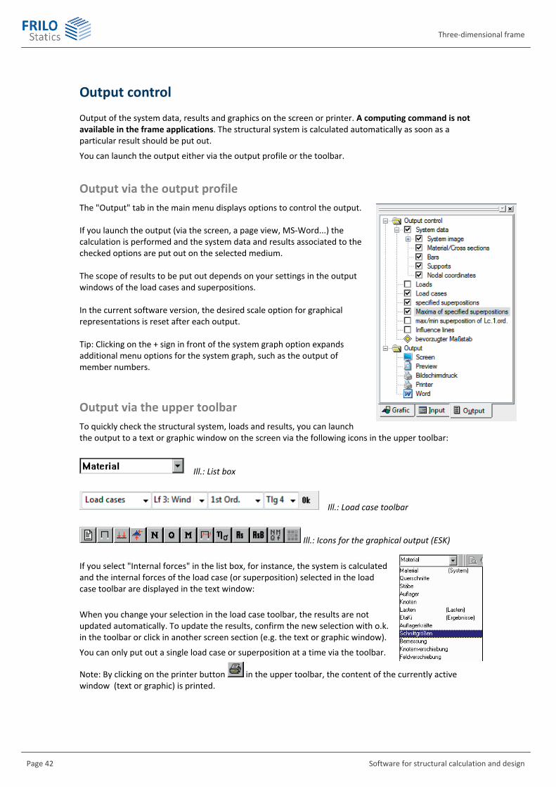
Three-dimensional frame
Page 42 Software for structural calculation and design
Output control
Output of the system data, results and graphics on the screen or printer. A computing command is not available in the frame applications. The structural system is calculated automatically as soon as a particular result should be put out.
You can launch the output either via the output profile or the toolbar.
Output via the output profile The "Output" tab in the main menu displays options to control the output.
If you launch the output (via the screen, a page view, MS-Word...) the calculation is performed and the system data and results associated to the checked options are put out on the selected medium. The scope of results to be put out depends on your settings in the output windows of the load cases and superpositions. In the current software version, the desired scale option for graphical representations is reset after each output. Tip: Clicking on the + sign in front of the system graph option expands additional menu options for the system graph, such as the output of member numbers.
Output via the upper toolbar To quickly check the structural system, loads and results, you can launch the output to a text or graphic window on the screen via the following icons in the upper toolbar:
Ill.: List box
Ill.: Load case toolbar
Ill.: Icons for the graphical output (ESK)
If you select "Internal forces" in the list box, for instance, the system is calculated and the internal forces of the load case (or superposition) selected in the load case toolbar are displayed in the text window:
When you change your selection in the load case toolbar, the results are not updated automatically. To update the results, confirm the new selection with o.k. in the toolbar or click in another screen section (e.g. the text or graphic window).
You can only put out a single load case or superposition at a time via the toolbar.
Note: By clicking on the printer button in the upper toolbar, the content of the currently active window (text or graphic) is printed.

RS
FRILO Software GmbH Page 43
Load cases / pre-set superpositions (output) The output for single load cases or pre-set superpositions on the screen or printer is controlled in the same way. The specifications below apply therefore to both cases.
Output
You can only put out load cases that you have checked in the "Output" column. By clicking on the column head, you can check or uncheck all load cases at a time.
Output via tables / graphical representation
The information in the lower window section associated to the table (internal forces, design, ...) and the graphical representation (M. Q, ....) always refers to the currently active cell of the currently active (yellow highlighted) load case, e.g. the displayed results of a second-order analysis of a particular load case.
Member segmentation
You can set the number of output points on a member for the internal forces and the design via the Member segmentation option ( page 44).
Apply to all load cases:
If you click on this button, all settings of the currently active cell are applied to all other checked cells.
EtaKi
If you check this column, the software calculates the buckling load factor Ki and the effective lengths of the system under the existing loading. The result of this calculation is not used in advanced verifications, e.g. an equivalent member analysis is not performed.
You can find further information about the buckling load factor Ki on page 52, 14.
Design
The following verifications are available:
Reinforced concrete design Timber design Steel analysis Aluminium analysis
Calculation
Depending on the information you have selected, the required calculations are performed automatically prior to the output.
Graphics
The graphical representations that should be put out can be selected in the lower window section.
Three-dimensional frame
Page 44 Software for structural calculation and design
Maximum values from pre-set superpositions (output) You can put out support reactions, deformations and the design for the maximum value calculation and include the numbers of the associated load cases / pre-set superpositions and graphs.
You can set the number of output points on a member for the internal forces and the design via the Member segmentation option.
Max./min. superposition from load cases in first-order analysis (output) You can put out support reactions, deformations and the design for the automatic max. /min. superposition and include the numbers of the associated load cases and graphs.
You can set the number of output points on a member for the internal forces and the design via the Member segmentation option.
Member segmentation The segmentation specifies the points (n-part points) on a member, at which values should be put out (in a table). The segmentations 1, 2, 4 or 8 produce the same output for the entire system. When specifying "-1", the member segmentation window is displayed that you can also access via the button.
The segmentation is relevant for the internal forces and the design.
Member segmentation window
This window allows you to assign segmentation points to the different members. The number of points may differ from member to member. From member ... to member
First and last member with the same segmentation.
Member segmentation
1 member ends
2 member ends and midspan
4 member ends and quarter-part points
8 member ends and eighth-part points
M maximum value in the member (for moments and the design/stress resistance verification). The point at which the maximum value is attained is put out as a percentage of the member lengths. The segmentation option M is not available in all cases.
Fast assignment of the member segmentation for particular system properties:
Via the member group not yet enabled
Via the cross section all members with a particular cross section are segmented in the same way.
Via the material all members with a particular material are segmented in the same way.

RS
FRILO Software GmbH Page 45
Results
The results described in this chapter refer to the Eurocode-specific calculation. Other standards requiring also a partial safety concept produce a similar output. In combination with older standards without partial safety concept, the corresponding notes to actions and -factors are not available.
Log of the applying loading Single load cases
For single load cases, the selected action, the defined loads and the sum of all exterior loads as well as your comments, if any, are put out prior to the results.
Pre-set superposition

Three-dimensional frame
Page 46 Software for structural calculation and design
The first table lists the participating actions and possible load and partial safety factors for the pre-set superposition. The second table reveals how the superposition was actually calculated, i.e. each load case is multiplied by the factor · for the superposition (if an action applies). The asterisk marks the defined leading action.
Maximum values resulting from pre-set superpositions
The first table lists the participating superpositions and the associated superposition rules.
Note: If a superposition is considered several times in the maximum value analysis (e.g. first-order and second-order), the consecutive number does no longer match the superposition number.
The second table lists the existing actions and the standard-dependent and factors for information.
Max./min. superpositions
The first table in the output of the max./min. superposition lists the superimposed load cases by specifying their names, the classification g, p or A (alternative) and the load factors used.
Only the load case factors defined in the "Factor" column are processed, no other load or partial safety factors are considered internally. Different leading actions in the various combinations are not considered in the max./min. superposition. Therefore, this type of superposition is only of limited suitability for standards prescribing combination factors.
The second table lists the applying actions with their standard-dependent and factors for information. These factors are not necessarily taken into account in the calculation.
Sway imperfections, second-order analyses or calculations of member failure or in accordance with the plastic hinge method are not available with a max./min. superposition.

RS
FRILO Software GmbH Page 47
Support reactions Support reactions are active forces that are positive when they act in the direction of the positive global axes or produce a clockwise rotation around the positive axes. Therefore, they can be used as direct transferring loads to other components.
Definition of the support reactions (active forces):
For the supported nodes, forces and moments are put out according to the defined supporting conditions. (see definition of supports, page 29 ). In addition, the total of the support reaction in x-, y- and z-direction is put out.
For rotated supports, an additional table with the support reactions in the rotated system of coordinates of the support is put out.
Note: The support reactions of the different superposition that are put out are always influenced by factors.
Single load cases and pre-set superpositions
The two tables below show the output of the support reactions with single load cases (pre-set superpositions accordingly). In this example, a rotated support is at node 1.

Three-dimensional frame
Page 48 Software for structural calculation and design
Maximum values resulting from pre-set superpositions
For the supported nodes, the support reactions, the pertinent support values and the decisive superposition are put out.
The asterisk always marks the support condition for which the maximum (upper row) or the minimum (lower row) was calculated. If applicable, the superposition that produced the listed result is specified in an additional table
Max./min. superposition
As for the max. values from pre-set superpositions, the support reactions are put out together with the associated support properties for the max./min. superposition.
If the "Associated load cases" option was checked for the output, a table is added that lists the load cases that produced the respective max./min. values.
The software does not necessarily detect the load case combination that is decisive for the transfer of the forces.
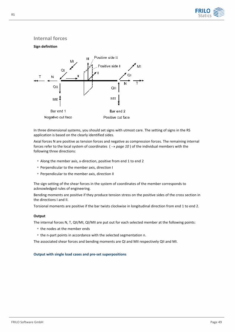
RS
FRILO Software GmbH Page 49
Internal forces Sign definition
In three dimensional systems, you should set signs with utmost care. The setting of signs in the RS application is based on the clearly identified sides.
Axial forces N are positive as tension forces and negative as compression forces. The remaining internal forces refer to the local system of coordinates ( page 10 ) of the individual members with the following three directions:
Along the member axis, x-direction, positive from end 1 to end 2
Perpendicular to the member axis, direction I
Perpendicular to the member axis, direction II
The sign setting of the shear forces in the system of coordinates of the member corresponds to acknowledged rules of engineering.
Bending moments are positive if they produce tension stress on the positive sides of the cross section in the directions I and II.
Torsional moments are positive if the bar twists clockwise in longitudinal direction from end 1 to end 2.
Output
The internal forces N, T, QII/MI, QI/MII are put out for each selected member at the following points:
the nodes at the member ends
the n-part points in accordance with the selected segmentation n.
The associated shear forces and bending moments are QI and MII respectively QII and MI.
Output with single load cases and pre-set superpositions

Three-dimensional frame
Page 50 Software for structural calculation and design
Maximum values resulting from pre-set superpositions
The maximum internal forces are put out together with the associated internal forces.
The asterisk always marks the internal force for which the maximum (upper row) or the minimum (lower row) was calculated. If applicable, the superposition that produced the listed result is specified in an additional table.
Max./min. superpositions
As for the max. values from pre-set superpositions, the max./min. internal forces are put out together with the associated internal forces for the max./min superposition.
The software does not necessarily find the load case combination that is decisive for the design because only the maximum of an internal force and a possible combination for the associated internal forces is sought after.
For the design, a result can become decisive, for instance, that lies between max. M and min M with an associated axial force and shear force.
If applicable, the load cases that produced the respective results are specified in an additional table.
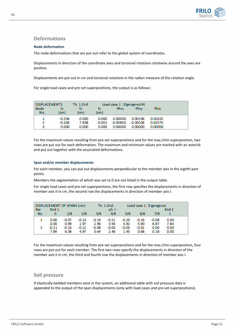
RS
FRILO Software GmbH Page 51
Deformations Node deformation
The node deformations that are put out refer to the global system of coordinates.
Displacements in direction of the coordinate axes and torsional rotations clockwise around the axes are positive.
Displacements are put out in cm and torsional rotations in the radian measure of the rotation angle.
For single load cases and pre-set superpositions, the output is as follows:
For the maximum values resulting from pre-set superpositions and for the max./min superposition, two rows are put out for each deformation. The maximum and minimum values are marked with an asterisk and put out together with the associated deformations.
Span and/or member displacements
For each member, you can put out displacements perpendicular to the member axis in the eighth-part points.
Members the segmentation of which was set to 0 are not listed in the output table.
For single load cases and pre-set superpositions, the first row specifies the displacements in direction of member axis II in cm, the second row the displacements in direction of member axis I.
For the maximum values resulting from pre-set superpositions and for the max./min superposition, four rows are put out for each member. The first two rows specify the displacements in direction of the member axis II in cm, the third and fourth row the displacements in direction of member axis I.
Soil pressure If elastically bedded members exist in the system, an additional table with soil pressure data is appended to the output of the span displacements (only with load cases and pre-set superpositions).
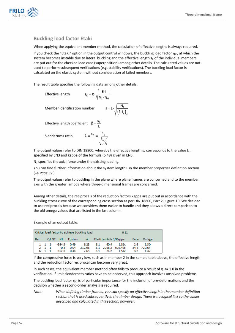
Three-dimensional frame
Page 52 Software for structural calculation and design
Buckling load factor Etaki When applying the equivalent member method, the calculation of effective lengths is always required.
If you check the "EtaKi" option in the output control windows, the buckling load factor Ki, at which the system becomes instable due to lateral buckling and the effective length sK of the individual members are put out for the checked load case (superposition) among other details. The calculated values are not used to perform subsequent verifications (e.g. stability verifications). The buckling load factor is calculated on the elastic system without consideration of failed members.
The result table specifies the following data among other details:
Effective length K1 Ki
E Is
N◊= p ◊◊h
Member identification number ( )1
y d
NL
E Ie = ◊
◊
Effective length coefficient KsL
b =
Slenderness ratio KK
y
ssi I
A
l = =
The output values refer to DIN 18800, whereby the effective length sK corresponds to the value Lcr specified by EN3 and kappa of the formula (6.49) given in EN3.
N1 specifies the axial force under the existing loading.
You can find further information about the system length L in the member properties definition section ( Page 32 )
The output values refer to buckling in the plane where plane frames are concerned and to the member axis with the greater lambda where three-dimensional frames are concerned.
Among other details, the reciprocals of the reduction factors kappa are put out in accordance with the buckling stress curve of the corresponding cross section as per DIN 18800, Part 2, Figure 10. We decided to use reciprocals because we considers them easier to handle and they allows a direct comparison to the old omega values that are listed in the last column.
Example of an output table:
If the compressive force is very low, such as in member 2 in the sample table above, the effective length and the reduction factor reciprocal can become very great.
In such cases, the equivalent member method often fails to produce a result of <= 1.0 in the verification. If limit slenderness ratios have to be observed, this approach involves unsolved problems.
The buckling load factor Ki is of particular importance for the inclusion of pre-deformations and the decision whether a second-order analysis is required.
Note: When defining timber frames, you can specify an effective length in the member definition section that is used subsequently in the timber design. There is no logical link to the values described and calculated in this section, however.

RS
FRILO Software GmbH Page 53
Plastic hinges The plastic frame calculation of load-bearing steel structures in accordance with the plastic hinge method was implemented for DIN 18800, but not for EN 3.
The calculations can be performed for single load cases and pre-set superpositions.
In the result output, each table is supplemented with the note:
Calculated with plastic moments
In the head of the internal forces table, the points are specified at which a plastic hinge was generated. In addition, the plastic moments are specified.
The points with plastic hinges are marked with a “P” in the internal forces table.
If a kinematic chain is generated in the calculation process due to too many plastic hinges the system becomes instable and the following message is put out:
An error occurred during the calculation of the plastic hinges.
Output example:
You can find further information in the chapter "Fundamentals of the plastic hinge method" ( page 14 and in the plastic internal forces table ( page 23).
Instability Instability in first-order analyses is mostly due to incorrect joint definitions and/or insufficient supports.
Example of an instability message displayed by the software application:
Instable system at JF=18 of NF=18, node 3.6.
The instability is not necessarily attributable to node 3. Decisive is the first decimal number which specifies the direction of the kinematics:
1 = kinematic in x-direction 4 = kinematic around the x-axis 2 = kinematic in y-direction 5 = kinematic around the y-axis 3 = kinematic in z-direction 6 = kinematic around the z-axis
A message referring to the decimal number 3 is often displayed for continuous beams that are not supported against torsional rotation around the member axis.
A message referring to the decimal number 6 is often displayed for columns that are pin-jointed on bottom and on top, but not supported against torsional rotation around the member axis.

Three-dimensional frame
Page 54 Software for structural calculation and design
If instability occurs in second-order analyses, this means that the system cannot bear the loading. A corresponding note is included in the output. We recommend verifying the deformation in a first-order analysis in this case.
Instability can also occur in calculations with member failure if the failure of a member causes kinematics in the structural system.
If a kinematic chain is generated by too many plastic hinges in the calculation in accordance with the plastic hinge method the structural system becomes instable too.
We recommend putting out also the deformations to support the evaluation of the results. This is of particular importance for non-linear methods of calculation such as second-order analyses.
Standards and verifications
The standards used for the structural system are selected in the material definition window. The calculation can be based on different safety concepts depending on the selected standard. There are standards with a global safety concept (older standards) or with a partial safety concept (e.g. Eurocode).
The description focuses on a calculation in accordance with the Eurocode. For a detailed description of the calculation in accordance with former standards that are still available for selection in the software please refer to previous versions of the operating instructions.
Standards that allow the assignment of actions to load cases in the load definition section are principally treated in the same way as the Eurocode.
We recommend entering the load cases always with their characteristic values, i.e. without additions due to safety factors.
The following is not considered in the frame:
Weakening of the cross section
Permissible reductions e.g. due to loads applying close to supports.
Design under fire exposure
General notes on the design as per Eurocode In the verification in the ultimate limit state, the permanent and transient design situations are assumed if no accidental action applies.
If an accidental action was defined, the accidental design situation is assumed.
No verifications are performed for the limit state of serviceability, but the support reactions, internal forces and deformations are put out.
In combination with pre-set superpositions, the partial safety factors and combination coefficients are set by the software in accordance with the design situation if the checkmark in the "Act.grp" column was not removed ( page 39).
In the max./min. superpositions of first-order load cases, only the load factors specified in the "Factor" column are taken into account, i. e. no other combination coefficients are set, because each point could have a different leading action (and/or combination) then and this is not supported by the software. The applicability must be checked in each individual case.

RS
FRILO Software GmbH Page 55
Reinforced concrete design State II, GammaM and effective rigidities If reinforced concrete frame systems or other components prone to buckling should be verified, the reduced stiffnesses in the cracked state (state II) must be taken into account, because they can have an important influence on the internal forces particularly in second-order analyses.
Unlike our column application B5, the frame application does not use these effective (reduced) stiffnesses in the calculation. However, there are two different approaches to consider stiffness reductions approximately in the frame application:
In the cross sections
When defining reinforced concrete cross sections, the reduction factors for I are optionally available. These factors allow the consideration of the relation of the stiffnesses in state I to the effective stiffnesses of failure in state II over the member length by approximation. This stiffness reduction is taken into account in first-order as well as second-order analyses and can be defined differently for each cross section. The effective stiffnesses depend among other factors on the location and size of the reinforcement and must be adjusted in several calculation steps, if applicable.
In the material definition window
The M value specified here (also referred to as GammaM in the software) is used for the reduction of the stiffnesses only in second-order analyses, i. e. the moduli of elasticity and shear are divided by this value. The same stiffness reduction is applied to the entire structural system. This is of course only a very rough approximation. This value is not used in the design.
The difference between the two approaches is that M applies to the entire system (only in second-order analyses) whereas the factors for I are set individually for each cross section (and can always be used). The effects of the two approaches overlap, i.e. if the reduction factor for the cross sections was calculated with consideration of the material safety coefficients (C for the concrete, S for the steel), you need not reduce the stiffnesses by M in addition and M can be set to 1 right away.
General notes on reinforced concrete design For the bending design, one of the following methods is selected automatically depending on the applicability and the steel requirements:
Design in accordance with the kd-method (or kh-method). This method is suitable for the design if pure bending and bending with axial tension or low axial pressure applies.
Method for cross sections with symmetrical reinforcement. This method is particularly suitable when compression force applies with little eccentricity. You can also use it universally.
The lever principle for bending without concrete compression zone and pure axial tension.
In the transition areas, the method involving the lowest steel requirement is used.
If biaxial bending applies, always the method for symmetrically reinforced cross sections is used.
For T-beams, only the web with the plate portion is taken into account as rectangular cross section if biaxial loading and MII moments apply.
Haunched members are replaced internally by several members with a constant cross section each. The member is divided into cross sections stepwise, which means that the slanted edge is not considered in the design.
No design is performed for shear force and torsion. You can do this in our B2 application.
The reinforcement layer is freely selectable, the minimum reinforcement distance is not examined.
The stress-strain curve of the concrete corresponds to the parabola rectangle stress diagram.

Three-dimensional frame
Page 56 Software for structural calculation and design
The total of the longitudinal reinforcement Asu put out for circular cross sections is distributed over the circumference.
A design can be performed with a single load case, if no materials with other standards have been defined.
Reinforced concrete design is not available for max. values from pre-set superpositions and the max./min. superposition.
Output of the longitudinal reinforcement:
In the output table of the longitudinal reinforcement, two values are specified for the required As, either ASIo and ASIu or ASIIo and ASIIu (o refers to the top, and u to the bottom).
If ASIo and ASIu are put out and both values are the same, the symmetrical method has been used.
The As that is put out must be distributed equally over the corners of the cross section, e.g. one half of ASIu must be placed in the left and the other half in the right corner of the positive cross section side II.
Note: A positive moment around axis I produces ASIu, which is located at the upper side of the beam, if the system of coordinates was defined as usual (z-axis runs upwards)!
For the definition of the axes I-II, see local system of coordinates of the member, page 10.
Design as per Eurocode
The material safety coefficients C and S are automatically set as required for the design situation.
The upper branch of the stress-strain curve of the reinforcing steel is considered in the design.
The following design values are put out:
Ned design value of the axial force. Mied,MIIed design moments around the axis I or II. ASIo, ASIu longitudinal reinforcement as shown in the illustration above. ASIo, ASIu longitudinal reinforcement as shown in the illustration above.
DIN 1045-1:2008 The general information of reinforced concrete design and the Eurocode-specific description apply.

RS
FRILO Software GmbH Page 57
Timber analysis General notes In timber design, the utilization ratio of the existing stresses is determined and the stability verifications for buckling and tilting are performed in accordance with the equivalent member method.
The required effective lengths are entered when defining the member ( page 26). The values in this table are treated as the data entered to define the system, i.e. the same effective lengths are used in all load cases. You should note in this connection that the effective lengths depend on the loading under particular conditions and that different effective lengths may apply to the individual load cases and superpositions. The applicability must be checked in each individual case.
You should note in addition that buckling and tilting is examined around both member axes in the timber design. In the plane frame, this is the only case where examinations out of plane are carried out.
Among other factors, the following details are not considered:
The direction of tension and compression applying under an angle. Loading perpendicular to the grain.
Note: The effective lengths determined by the software in the calculation of the buckling load ( page 52, 14) have no logical link to the effective length table for the timber design ( page 26).
Eurocode The stiffness reduction in the usage classes 2 and 3 is taken into account if the self-weight portion of the axial force is greater than 70 %. In this case, the modulus of elasticity is multiplied by the factor 1/(1+kdef) in the stability verification. The buckling and tilting coefficients are reduced through this.
Output values:
Nd, Md, Qd design values of the axial force, the moment and the shear force. M partial safety coefficient of the material for the design. Nkl usage class determined by the timber species: 1 = coniferous wood, 2 = laminated timber, 3 = deciduous wood kmod modification coefficient of the strength, depends on the usage class and the load-
action period. kdef deformation coefficient, depends on the usage class. kc buckling coefficient. kcrit tilting coefficient Ng self-weight portion of the axial force in per cent. Nd existing axial stress resulting from axial force. md existing bending stress due to moment loading. d existing shear stress resulting from shear force. tord existing shear stress resulting from torsion (only three-dimensional frame). utilization ratio of the axial stress or the stability. The greater of both values is put out. utilization ratio of the shear stress.
Note: If the utilization ratio is too high, this might be attributable to the stability verification. If the component is safeguarded against buckling or tilting, you can simulate this by setting the effective lengths to small values in the member definition section.
DIN 1052:2008 In the frame application, the calculation in accordance with DIN 1052:2008 produces for the most part the same results as per DIN EN 1995. You should note that the tilting coefficient in DIN 1052:2008 is represented by km.
Three-dimensional frame
Page 58 Software for structural calculation and design
Steel analysis General notes Please note that the frame application does not perform any verifications of the resistance against lateral torsional buckling or stability verifications on equivalent members.
Elastic stress analysis:
For the calculation of stresses, section moduli and shear areas must be known.
Detailed specifications concerning the behaviour of the shear and comparison stresses can only be made if the dimensions of the cross section are known.
If the cross sections are selected from the F+L profile selection file or defined by specifying the steel dimensions ( page 18), all parameters are available in the software for a more accurate stress calculation. The axial stresses, the shear stresses and the Von-Mises comparison stresses are determined at several decisive points of the profile and the most unfavourable utilization ratio is put out.
If the cross sections were defined via the structural parameters I, A, W or the Frilo applications Q2 or Q3, the comparison stress cannot be calculated accurately, because the behaviour of the shear stresses is not known. The comparison stress put out by the software can be too great in this case.
Position of the cross section:
If cross sections have been taken from the F+L profile selection file or defined via their dimensions, they are installed in the system either in their "Normal position" ( page 21) or rotated by 90°, as in most civil engineering structures.
Consequently, the main axes of inertia of asymmetrical profiles such as L-shapes do not lie in the system plane.
When considering a cantilever with an L-shape in a three-dimensional examination, it may happen that a load in the system plane causes also deformation and internal forces out of the system plane.
Verification as per Eurocode The verification of steel cross sections as per EN 1993-1-1 produces two tables.
The one table refers to the elastic stress analysis based on equation 6.1 the other to the cross section analysis based on equation 6.2. The verification is successful if one of the two equations gives a permissible utilization.
Only thin-walled cross sections with plane cross section parts are examined.
Note: The verification in accordance with the plastic hinge method is not implemented in EN3.
Available are the materials listed in table 3.1 (structural steel).
For the ultimate limit states, the following partial safety factors apply:
M0 = 1.0
M1 = 1.0 (as per DIN EN 1993: M1 = 1.1)
M2 = 1.25

RS
FRILO Software GmbH Page 59
The cross sections are categorized in four cross section classes (QKL):
Class 1 the cross sections can generate plastic hinges or yield zones with sufficient resistance to plastic moments and rotation capacity for the plastic calculation.
Class 2 the cross sections can develop resistance to plastic moments but have only a limited rotation capacity due to local buckling.
Class 3 the cross sections reach the yield point in the most unfavourable fibre, but cannot develop resistance to plastic moments due to local buckling.
Class 4 local buckling occurs in these cross sections in one or several parts before the yield point is attained.
The classification of a cross section depends on the width/thickness ratio c/t of its parts under compression, on the position of the plastic zero line () for class 1 and 2 or the position of the elastic zero line for class 3 and on � (yield point of the material); see also table 5.2.
A cross section is categorized by the most unfavourable class of its parts under compression.
Cross sections of class 4 can be calculated with effective widths in accordance with EN 1993-1-5, 5.2.2 to take local buckling into account. This calculation is implemented for I-shapes and rectangular pipes.
Cross sections that have been defined with the help of the structural I, A, W values cannot be classified due to missing dimensions. The verification based on eq. 6.1 is available in the software but probably not permissible. The verification based on eq. 6.2 is not available for these cross sections.
Design resistance of the cross sections
The design resistance of the cross sections is determined in accordance with paragraph 6.2.
In this calculation, the condition specified by eq. (6.1), yield criterion for the critical point of the cross section, is checked (cross section class 1 to 4):
- The effective stiffnesses are verified in this calculation for class 4.
A modification of the initial internal forces due to a displacement of the centre of gravity is not considered.
In addition, the design resistance of the cross section as specified by the paragraphs 6.2.3 to 6.2.9 is determined with the help of eq. (6.2) (cross section class 1 to 3):
- The axial force resistance NRd is calculated using eq. (6.10).
- Bending resistance under uniaxial bending is determined as per paragraph 6.2.5, whereby the plastic resistance forces eq. (6.13) are used for class 1 and 2 and the elastic resisting forces eq. (6.14) for class 3.
- Shear design resistance is determined in accordance with the paragraphs 6.2.6 and 6.2.7.
A reduction of VRd due to shear buckling as per EN 1993-1-5 is taken into account in this connection.
- The resistance to bending and shear force is determined as specified by paragraph 6.2.8:
If the design value VEd exceeds half of the shear force resistance VRd, the cross section parts under shear load are calculated with a reduced yield point as per eq. (6.29).
Eq. (6.30) is used for I-cross sections with identical flanges under uniaxial bending around the main axis.
- For bending with axial force, the design resistances are calculated in accordance with paragraph 6.2.9.
In this calculation, equation (6.41) is only used if biaxial bending with axial force applies.

Three-dimensional frame
Page 60 Software for structural calculation and design
Output values:
N/Mt,ed design values of the axial force and torsion. My/z,ed design values of the moments around the y-axis (axis I) and the z-axis (axis II). Vz/y,ed design values of the shear forces applying in the z-direction (axis II) and the y-direction
(axis I). QKL cross section class, depending on the shape geometry and the loading. V comparison stress in the verification based on eq. 6.1. shear stress in the verification based on eq. 6.1. utilization ratio of the stress existing in the critical point as per 6.1 or the cross
sectional resistance as per 6.2. factor for the consideration of the shear force influence on the resistance to moments. MRd design value of the bending design resistance in the verification based on eq. 6.2.
On top of the verification tables, a table with the plastic properties of the existing cross sections is put out.
Verification as per DIN 18800 with actions as per DIN 1055-100 The results of the calculation based on DIN 18800 are comparable to those based on the Eurocode, eq. 6.1.
Slight differences result mainly from the inclusion of variable yield stresses (240 to 235 N/m) and the safety coefficient �M (1.1 to 1.0) in second-order analyses.

RS
FRILO Software GmbH Page 61
Aluminium analysis General notes To aluminium apply the same general notes as to steel.
Verification as per Eurocode The verification of the profile as per EN 1999-1-1 produces two tables.
The one refers to the elastic stress analysis based on the equations (6.15) and (6.15 a, b, c), the other to the cross section analysis in accordance with the paragraphs 6.2.3 to 6.2.10. The verification is successful if one of the two equations gives a permissible utilization.
Only cross sections with plane parts are considered, i. e. no curved or stiffened cross section parts, no welded profiles, i.e. without heat influence zones (WEZ).
Available for selection are the materials specified by - table 3.2b (wrought aluminium alloys - extruded profile) and by - table 3.2c (wrought aluminium alloys - forged products).
For the ultimate limit states, the following partial safety factors apply:
For the design resistance of cross-sections and of components in stability failures (component verifications):
M1 = 1.1
For the design resistance of cross sections in breakage failures under tension:
M2 = 1.25
The cross sections are categorized in four cross section classes (QKL):
Class 1 the cross sections can generate plastic hinges or yield zones with sufficient resistance to plastic moments and rotation capacity for the plastic frame calculation.
Class 2 the cross sections can develop resistance to plastic moments but have only a limited rotation capacity due to local buckling.
Class 3 the cross sections reach the elastic limit in the outermost fibre under compression, but cannot develop resistance to plastic moments due to local buckling.
Class 4 local buckling occurs in these cross sections in one or several parts before the elastic limit is attained.
The classification of a cross section depends on the width/thickness ratio b/t of its parts under compression and on the stress behaviour (figure 6.2) at the cross section part.
For each cross section part, the slenderness parameter is determined that takes both parameters into account (para. 6.1.4.3). The elastic zero line position is used for this purpose. Depending on the material (fy and the resulting , class A or B, unwelded) the limits for 1,23 are determined for the classification of the cross section part.
Class 4 cross sections are calculated with effective thicknesses in order to take local buckling into account. A local buckling factor c (equations (6.11, 6.12)) for the reduction of the thickness of the cross section part is determined in accordance with para. 6.1.5. The factor depends on the material class A or B (unwelded), and .
Cross sections that have been defined with the help of the structural I, A, W values cannot be classified due to missing dimensions. The stress resistance verification based on eq. 6.15 is available in the software but probably not permissible. The cross section verification in accordance with the paragraphs 6.2.3 et seq. is not available for these cross sections.

Three-dimensional frame
Page 62 Software for structural calculation and design
Design resistance of the cross sections
The design resistance of the cross sections is determined in accordance with paragraph 6.2.
The conditions as per eq. (6.15) and eq. (6.15 a, b, c) - yield criterion for the critical point of the cross sections are checked in this calculation.
Eq. (6.15) is rearranged to place the constant C, which is 1.2 in accordance with DIN EN 1999-1-1 on the left side. The verification always checks the permissibility of against 1.0.
In addition, the design resistances are determined in accordance with the paragraphs 6.2.3 to 6.2.10.
The resistance to axial loads NRd is the smaller value of the results obtained by the equations (6.21) and (6.22).
The bending resistance under uniaxial bending is determined in accordance with paragraph 6.2.5. The cross section class and the resulting shape coefficient 3 as per table 6.4. are taken into account in this calculation.
The shear design resistance is determined in accordance with the paragraphs 6.2.6 and 6.2.7.
You should note in this connection that the shear area Av is not calculated as per EN 1993-1-1 (steel cross sections).
The design resistance against uniform shear stresses is checked in accordance with paragraph 6.5.5.
The resistance to bending and shear force is determined as specified by paragraph 6.2.8:
If the design value VEd exceeds half of the shear force resistance VRd, the cross section parts under shear load are calculated with a reduced yield point as per eq. (6.29).
For bending with axial force, the design resistances are calculated in accordance with paragraph 6.2.9.
Web crippling as per paragraph 6.2.11 is not taken into account.
Output values:
N/Mt,ed design values of the axial force and torsion. My/z,ed design values of the moments around the y-axis (axis I) and the z-axis (axis II). Vz/y,ed design values of the shear forces applying in the z-direction (axis II) and the y-direction
(axis I). QKL cross section class, depending on the shape geometry and the loading. V comparison stress in the verification based on the equations (6.15). shear stress in the verification based on eq. (6.15). utilization ratio of the existing stress based on the equations (6.15) or of the cross
sectional resistance as per paragraph 6.2.3 et. seq. factor for the consideration of the influence of the shear force on the design resistance
against moments based on eq. (6.47). MRd value of the bending design resistance in accordance with para. 6.2.3 et seq.
On top of the verification tables, a table with the plastic properties of the existing cross sections is put out.
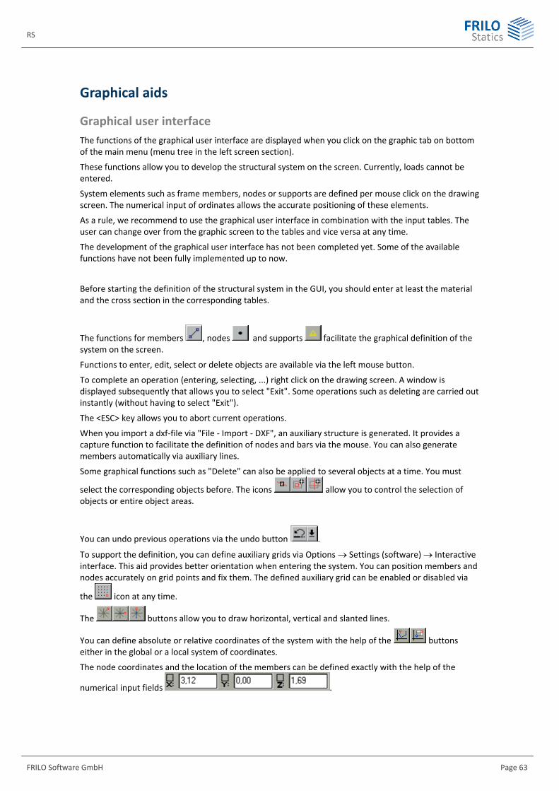
RS
FRILO Software GmbH Page 63
Graphical aids
Graphical user interface The functions of the graphical user interface are displayed when you click on the graphic tab on bottom of the main menu (menu tree in the left screen section).
These functions allow you to develop the structural system on the screen. Currently, loads cannot be entered.
System elements such as frame members, nodes or supports are defined per mouse click on the drawing screen. The numerical input of ordinates allows the accurate positioning of these elements.
As a rule, we recommend to use the graphical user interface in combination with the input tables. The user can change over from the graphic screen to the tables and vice versa at any time.
The development of the graphical user interface has not been completed yet. Some of the available functions have not been fully implemented up to now.
Before starting the definition of the structural system in the GUI, you should enter at least the material and the cross section in the corresponding tables.
The functions for members , nodes and supports facilitate the graphical definition of the system on the screen.
Functions to enter, edit, select or delete objects are available via the left mouse button.
To complete an operation (entering, selecting, ...) right click on the drawing screen. A window is displayed subsequently that allows you to select "Exit". Some operations such as deleting are carried out instantly (without having to select "Exit").
The <ESC> key allows you to abort current operations.
When you import a dxf-file via "File - Import - DXF", an auxiliary structure is generated. It provides a capture function to facilitate the definition of nodes and bars via the mouse. You can also generate members automatically via auxiliary lines.
Some graphical functions such as "Delete" can also be applied to several objects at a time. You must
select the corresponding objects before. The icons allow you to control the selection of objects or entire object areas.
You can undo previous operations via the undo button .
To support the definition, you can define auxiliary grids via Options Settings (software) Interactive interface. This aid provides better orientation when entering the system. You can position members and nodes accurately on grid points and fix them. The defined auxiliary grid can be enabled or disabled via
the icon at any time.
The buttons allow you to draw horizontal, vertical and slanted lines.
You can define absolute or relative coordinates of the system with the help of the buttons either in the global or a local system of coordinates.
The node coordinates and the location of the members can be defined exactly with the help of the
numerical input fields .

Three-dimensional frame
Page 64 Software for structural calculation and design
Graphical representation You can change the graphical representation of the structural system via various functions in the toolbars or the context-sensitive menu accessible via the right mouse button. The available options depend on the screen section where you click with the right mouse button.
More information on the graphical representation of the results is available on page 42.
View toolbar
The buttons allow you to rotate, displace the view or zoom it in and out.
You can exit the function mode via the ESC key.
Toolbar at the right
The toolbar at the right border of the screen allows you to enable or disable particular graphical elements such as member and node numbers, the system of coordinates, the local member axes, the cross section representation, the support symbols or the dimensioning.
Moreover, you can change the text size or select another representation plane.
Member selection
For the control and result representation of larger structural systems, it can be helpful to limit the number of members shown on the screen to a manageable level.
When you select a member, particular system parts are hidden in the "background" or hidden parts are displayed in the "foreground".
Activating the member selection button displays the window below:
How to proceed:
1. Selection of members:
First select the desired members. All input options with exception of the buttons in the lower section can be used to select members. You can also select the desired members by clicking on them.
2. Definition of the visible system:
When activating this icon, only the selected members are shown (in the foreground).
The selected members are hidden in the background.
Reverses the foreground and background elements.
Displays the entire system in the foreground and deselects the previously selected members.
Additional buttons
When activating the OpenGL button, the system is shown in a "rendered", photo-realistic view (illuminated solid model). You can easily check the locations of cross sections in this view

RS
FRILO Software GmbH Page 65
When activating the value button, details on the object at the mouse cursor (e. g. member, node, support, ...) are displayed.
If you move the mouse over the vertical state lines of result curves (e.g. M behaviour), the corresponding result value is displayed. If you click on the state line, the value remains displayed on the screen an can be printed.
Scaling of results
Activating the menu item "Scale graphic" displays a dialog that allows you to change the size of the representation of various graphic elements such of the system, the loads or the results.