r&s zvh-k40 remote control via lan or usb - rohde & … · remote control via lan or usb...
TRANSCRIPT

R&S®ZVH Remote Control via LAN or USB Software Manual
1173.9005.12 – 08
Test
& Me
asur
emen
t
Softw
are M
anua
l

The Software Manual describes the following R&S®ZVH models and options
● R&S ZVH-K40 (1309.7013.02)
for the R&S®ZVH models:
● R&S ZVH4 (1309.6800.24) ● R&S ZVH8 (1309.6800.28)
The contents of this manual correspond to firmware version 1.52 or higher.
© 2016 Rohde & Schwarz GmbH & Co. KG Muehldorfstr. 15, 81671 Munich. Germany Phone: +49 89 4129-0 Fax: +49 89 4129-12 164 E-mail: [email protected] Internet: http://www.rohde-schwarz.com 81671 Munich, Germany Subject to change – Data without tolerance limits is not binding. R&S® is a registered trademark of Rohde & Schwarz GmbH & Co. KG. Trade names are trademarks of the owners. The following abbreviations are used throughout this manual: R&S®ZVH is abbreviated as R&S ZVH.

R&S ZVH Table of Contents
Software Manual 1173.9005.12 - 08 1
Table of Contents Documentation Overview ................................................................... 6
Conventions Used in the Documentation ......................................... 7
1 Introduction ......................................................................................... 8
2 Interfaces and Protocols .................................................................... 9
2.1 LAN Interface ..............................................................................................................11
2.2 USB Interface .............................................................................................................11
2.3 Protocols ....................................................................................................................12
3 Setting Up the Remote Control Connection ................................... 14
3.1 Preparing for Remote Control ..................................................................................14
4 Instrument Model and Command Processing ................................ 15
4.1 Input Unit ....................................................................................................................15
4.2 Command Recognition .............................................................................................16
4.3 Data Base and Instrument Hardware .......................................................................16
4.4 Status Reporting System ..........................................................................................17
4.5 Output Unit .................................................................................................................17
5 SCPI Command Structure and Syntax ............................................ 18
5.1 Structure of a Command ...........................................................................................19
5.1.1 Common Commands ...................................................................................................19
5.1.2 Device-Specific Commands .........................................................................................20
5.1.2.1 Hierarchy ......................................................................................................................20
5.1.2.2 Multiple Keywords ........................................................................................................20
5.1.2.3 Optional Keywords .......................................................................................................21
5.1.2.4 Long and Short Form ...................................................................................................21
5.1.2.5 Parameter ....................................................................................................................22
5.1.2.6 Special Characters.......................................................................................................22
5.1.2.7 Numeric Suffix ..............................................................................................................23
5.1.3 Overview of Syntax Elements ......................................................................................24
5.2 Parameters .................................................................................................................25
5.2.1 Numeric Values ............................................................................................................25
R&S ZVH Table of Contents
Software Manual 1173.9005.12 - 08 2
5.2.2 Special Numeric Values ...............................................................................................26
5.2.3 Boolean Parameters ....................................................................................................26
5.2.4 Text ..............................................................................................................................27
5.2.5 Strings ..........................................................................................................................27
5.2.6 Block Data ....................................................................................................................27
5.3 Structure of a Program Message .............................................................................28
5.4 Responses to Queries ...............................................................................................29
6 Command Sequence and Command Synchronization .................. 30
7 Remote Control – Commands ......................................................... 31
7.1 Common Commands .................................................................................................32
7.2 Remote Commands of the Cable and Antenna Analyzer ......................................35
7.2.1 Configuring the Horizontal Axis ...................................................................................36
7.2.2 Configuring the Vertical Axis ........................................................................................41
7.2.3 Setting the Bandwidth ..................................................................................................47
7.2.4 Performing and Triggering Measurements ..................................................................48
7.2.4.1 Performing the Measurement ......................................................................................48
7.2.4.2 Triggering Measurements ............................................................................................48
7.2.5 Working with Traces ....................................................................................................50
7.2.6 Using Markers ..............................................................................................................54
7.2.7 Using Limit Lines..........................................................................................................63
7.2.8 Configuring and Using Measurement Functions .........................................................64
7.2.8.1 Selecting the Measurement Port .................................................................................64
7.2.8.2 Selecting the Cable Characteristics .............................................................................65
7.2.8.3 Selecting the Measurement Mode ...............................................................................65
7.2.8.4 Selecting the Measurement Format.............................................................................66
7.2.8.5 Reading Out Measurement Results.............................................................................67
7.2.8.6 Calibrating the Measurement .......................................................................................68
7.2.8.7 Working with a DTF List ...............................................................................................72
7.3 Remote Commands of the Spectrum Analyzer ......................................................74
7.3.1 Configuring the Horizontal Axis ...................................................................................75
7.3.2 Configuring the Vertical Axis ........................................................................................80
7.3.3 Setting the Bandwidths ................................................................................................86
7.3.4 Performing and Triggering Measurements ..................................................................88

R&S ZVH Table of Contents
Software Manual 1173.9005.12 - 08 3
7.3.4.1 Performing the Measurement ......................................................................................88
7.3.4.2 Triggering Measurements ............................................................................................91
7.3.5 Working with Traces ....................................................................................................94
7.3.6 Using Markers ..............................................................................................................99
7.3.6.1 Markers and Delta Markers .........................................................................................99
7.3.6.2 Marker Functions .........................................................................................................99
7.3.7 Using Display Lines and Limit Lines ..........................................................................106
7.3.7.1 Display Lines ..............................................................................................................106
7.3.7.2 Limit Lines ..................................................................................................................107
7.3.8 Configuring and Using Measurement Functions .......................................................112
7.3.8.1 Working with Channel Tables ....................................................................................112
7.3.8.2 Power Measurements ................................................................................................115
7.3.8.3 Measuring the Channel Power ..................................................................................118
7.3.8.4 Measuring the Occupied Bandwidth ..........................................................................120
7.3.8.5 TDMA Measurements ................................................................................................121
7.3.8.6 Measuring the Adjacent Channel Leakage Ratio ......................................................122
7.3.8.7 Measuring the Harmonic Distortion ...........................................................................134
7.3.8.8 Measuring the AM Modulation Depth ........................................................................136
7.3.8.9 Measuring the Spectrum Emission Mask ..................................................................137
7.3.8.10 Measuring Spurious Emissions .................................................................................139
7.3.8.11 Using an Isotropic Antenna ........................................................................................140
7.4 Remote Commands of the Network Analyzer Mode ............................................142
7.4.1 Configuring the Horizontal Axis .................................................................................142
7.4.2 Configuring the Vertical Axis ......................................................................................143
7.4.3 Setting the Bandwidths ..............................................................................................148
7.4.4 Performing and Triggering the Measurement ............................................................148
7.4.5 Working with Traces ..................................................................................................149
7.4.6 Using Markers and Deltamarkers ..............................................................................151
7.4.6.1 Markers and Deltamarkers ........................................................................................151
7.4.6.2 Marker Functions .......................................................................................................153
7.4.7 Configuring the Measurement ...................................................................................155
7.4.7.1 Selecting the Measurement Port ...............................................................................155
7.4.7.2 Selecting the Measurement Mode .............................................................................155

R&S ZVH Table of Contents
Software Manual 1173.9005.12 - 08 4
7.4.7.3 Calibrating the Measurement .....................................................................................156
7.4.7.4 Selecting the Result Display ......................................................................................157
7.4.7.5 Selecting the Measurement Format...........................................................................158
7.4.7.6 Configuring the Vector Voltmeter (option R&S ZVH-K45) .........................................160
7.5 Remote Commands of the Power Meter ................................................................163
7.5.1 Using Power Sensors ................................................................................................163
7.5.1.1 Setting the Frequency ................................................................................................163
7.5.1.2 Configuring Power Level Readout .............................................................................164
7.5.1.3 Defining the Measurement Time ................................................................................166
7.5.1.4 Zeroing of the Power Sensor .....................................................................................166
7.5.1.5 Forward Power Display ..............................................................................................167
7.5.1.6 Defining the Video Bandwidth ....................................................................................167
7.5.1.7 Reading Out Measurement Results...........................................................................168
7.5.1.8 Selecting a Telecommunication Standard .................................................................169
7.6 File Management ......................................................................................................170
7.7 Making and Storing Screenshots ...........................................................................178
7.8 Configuring Data Capture .......................................................................................180
7.9 Saving Events ..........................................................................................................182
7.10 Configuring the Instrument ....................................................................................185
7.10.1 Mode Selection ..........................................................................................................185
7.10.2 Controlling the GPS Receiver ....................................................................................187
7.10.3 Display Configuration .................................................................................................191
7.10.4 Audio Settings ............................................................................................................193
7.10.5 Setting up a Network Connection ..............................................................................195
7.10.6 System Settings .........................................................................................................197
7.11 Status Reporting System ........................................................................................207
7.11.1 Structure of an SCPI Status Register ........................................................................207
7.11.1.1 CONDition part ...........................................................................................................207
7.11.1.2 PTRansition part ........................................................................................................208
7.11.1.3 NTRansition part ........................................................................................................208
7.11.1.4 EVENt part .................................................................................................................208
7.11.1.5 ENABle part ...............................................................................................................208
7.11.1.6 Sum bit .......................................................................................................................209

R&S ZVH Table of Contents
Software Manual 1173.9005.12 - 08 5
7.11.2 Overview of the Status Register ................................................................................209
7.11.3 Status Byte (STB) & Service Request Enable Register (SRE) .................................210
7.11.4 Event Status Register (ESR) and Event Status Enable Register (ESE) ...................211
7.11.4.1 STATus:OPERation Register ....................................................................................212
7.11.4.2 STATus:QUEStionable Register ................................................................................212
7.11.4.3 STATus:QUEStionable:FREQuency Register ...........................................................213
7.11.4.4 STATus:QUEStionable:LIMit Register .......................................................................213
7.11.4.5 STATus:QUEStionable:POWer Register ...................................................................213
7.11.5 Application of the Status Reporting Systems ............................................................214
7.11.5.1 Service Request .........................................................................................................214
7.11.5.2 Serial Poll ...................................................................................................................214
7.11.5.3 Query by Means of Commands .................................................................................215
7.11.5.4 Error Queue Query ....................................................................................................215
7.11.6 Reset Values of the Status Reporting System ..........................................................216
7.11.7 Remote Commands of the Status Reporting System ................................................217
Alphabetical List of Remote Commands ...................................... 222
Index ................................................................................................ 231

R&S ZVH Documentation Overview
Software Manual 1173.9005.12 - 08 6
Documentation Overview The user documentation for the R&S ZVH is divided as follows:
Quick Start Guide
The Quick Start Guide provides basic information on the instrument's functions.
It covers the following topics:
● overview of all elements of the front and rear panels ● basic information on how to set up the R&S ZVH ● information on how to operate the R&S ZVH in a network ● instructions on how to perform measurements
Operating Manual
The Operating Manual provides a detailed description on the instrument's functions
It covers the following topics:
● instructions on how to set up and operate the R&S ZVH in its various operating modes
● instructions on how to perform measurements with the R&S ZVH ● instructions on how to work with the available software options and applications
Service Manual
The Service Manual provides information on maintenance.
It covers the following topics:
● instructions on how to perform a performance test ● instructions on how to repair the R&S ZVH including a spare parts list ● mechanical drawings
Release Notes
The release notes describe the installation of the firmware, new and modified functions, eliminated problems, and last minute changes to the documentation. The corresponding firmware version is indicated on the title page of the release notes. The current release notes are provided on the internet.
Internet Site
The internet site at: http://www.rohde-schwarz.com/product/zvh.html provides the most up to date information on the R&S ZVH. The most recent manuals are available as printable PDF files in the download area.
Also provided for download are firmware updates including the corresponding release notes, instrument drivers, current data sheets, application notes and image versions.

R&S ZVH Conventions Used in the Documentation
Software Manual 1173.9005.12 - 08 7
Conventions Used in the Documentation The following conventions are used throughout the R&S R&S ZVH Software Manual:
Typographical conventions
Convention Description
“Graphical user interface elements” All names of graphical user interface elements both on the screen and on the front and rear panels, such as dialog boxes, softkeys, menus, options, buttons etc., are enclosed by quotation marks.
“KEYS” Key names are written in capital letters and enclosed by quotation marks.
Input Input to be entered by the user is displayed in italics.
File names, commands, program code
File names, commands, coding samples and screen output are distinguished by their font.
"Links" Links that you can click are displayed in blue font.
"References" References to other parts of the documentation are enclosed by quotation marks.
Other conventions
● Remote commands: Remote commands may include abbreviations to simplify input. In the description of such commands, all parts that have to be entered are written in capital letters. Additional text in lower-case characters is for information only.

R&S ZVH Introduction
LAN Interface
Software Manual 1173.9005.12 - 08 8
1 Introduction With the software application R&S ZVH-K40 installed on the instrument, it is possible to operate your R&S ZVH via remote control. In this manual you will find all information necessary to remotely control the R&S ZVH.
Enabling the Option
The Remote Control Option R&S ZVH-K40 is enabled by entering a key code. The key code is based on the unique serial number of the instrument. To retrofit an option, enable it with a key code.
► Press the SETUP key.
► Press the "Installed Options" softkey
► Select "Install Option..." under the "Option Administration" header.
► Confirm with ENTER.
An entry box in the lower right corner of the screen is displayed.
► Type in the the appropriate option key.
► Confirm with ENTER.
If the correct key code is entered, the R&S ZVH displays
If an invalid key code is entered, the R&S ZVH displays

R&S ZVH Interfaces and Protocols
LAN Interface
Software Manual 1173.9005.12 - 08 9
2 Interfaces and Protocols The R&S ZVH supports two different interfaces for remote control.
● LAN Interface: The protocol is based on TCP/IP and supports the VXI-11 standard. ● USB Interface
The connectors are located at the side of the instrument and permit a connection to a controller for remote control via a local area network (LAN) or directly via USB.
SCPI
SCPI (Standard Commands for Programmable Instruments) commands - messages - are used for remote control. Commands that are not taken from the SCPI standard follow the SCPI syntax rules. The instrument supports the SCPI version 1999. The SCPI standard is based on standard IEEE 488.2 and aims at the standardization of device-specific commands, error handling and the status registers. The tutorial "Automatic Measurement Control - A tutorial on SCPI and IEEE 488.2" from John M. Pieper (R&S order number 0002.3536.00) offers detailed information on concepts and definitions of SCPI.
The requirements that the SCPI standard places on command syntax, error handling and configuration of the status registers are explained in detail in the following sections. Tables provide a fast overview of the bit assignment in the status registers. The tables are supplemented by a comprehensive description of the status registers.
VISA
VISA is a standardized software interface library providing input and output functions to communicate with instruments. The I/O channel (LAN or USB) is selected at initialization time by means of a channel-specific resource string. For more information about VISA refer to its user documentation.
The programming examples for remote control are all written in Microsoft® VISUAL BASIC®. Access to the VISA functions require the declaration of the functions and constants prior to their use in the project. This can be accomplished either by adding the modules VISA32.BAS and VPPTYPE.BAS or a reference to the VISA32.DLL to the project.

R&S ZVH Interfaces and Protocols
LAN Interface
Software Manual 1173.9005.12 - 08 10
The modules visa32.bas and vpptype.bas can be found in the following location:
<VXIpnpPath>\WinNT\include (typically C:\VXIpnp\WinNt\include).
Resetting the R&S ZVH Manual operation is designed for maximum possible operating convenience. In contrast, the priority of remote control is the "predictability" of the device status. Therefore, control programs should always define an initial device status (e.g. with the command *RST) and then implement the required settings.

R&S ZVH Interfaces and Protocols
LAN Interface
Software Manual 1173.9005.12 - 08 11
2.1 LAN Interface
To be integrated in a LAN, the instrument is equipped with a standard LAN interface, consisting of a connector, a network interface and protocols (VXI-11).
Instrument access via VXI-11 is usually achieved from high level programming platforms by using VISA as an intermediate abstraction layer. VISA encapsulates the low level VXI-11 (LAN) or USB function calls and thus makes the transport interface transparent for the user. The necessary VISA library is available as a separate product. For details contact your local R&S sales representative.
2.2 USB Interface
For remote control via the USB connection, the PC and the instrument must be connected via the USB interface. The required driver comes with the R&S ZVHView software package and is automatically installed on the PC with the software package.
The driver adresses the instrument via the USB interface with the fix IP address 172.16.10.10.
In addition, a remote control connection via the SCPI interface requires the VISA library to be installed on the PC.
R&S ZVH Interfaces and Protocols
Protocols
Software Manual 1173.9005.12 - 08 12
2.3 Protocols
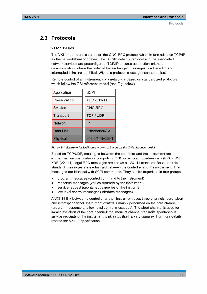
VXI-11 Basics
The VXI-11 standard is based on the ONC-RPC protocol which in turn relies on TCP/IP as the network/transport layer. The TCP/IP network protocol and the associated network services are preconfigured. TCP/IP ensures connection-oriented communication, where the order of the exchanged messages is adhered to and interrupted links are identified. With this protocol, messages cannot be lost.
Remote control of an instrument via a network is based on standardized protocols which follow the OSI reference model (see Fig. below).
Application SCPI
Presentation
Session
Transport
Network
Data Link
Physical
XDR (VXI-11)
ONC-RPC
TCP / UDP
IP
Ethernet/802.3
802.3/10BASE-T
Figure 2-1: Example for LAN remote control based on the OSI reference model
Based on TCP/UDP, messages between the controller and the instrument are exchanged via open network computing (ONC) - remote procedure calls (RPC). With XDR (VXI-11), legal RPC messages are known as VXI-11 standard. Based on this standard, messages are exchanged between the controller and the instrument. The messages are identical with SCPI commands. They can be organized in four groups:
● program messages (control command to the instrument) ● response messages (values returned by the instrument) ● service request (spontaneous queries of the instrument) ● low-level control messages (interface messages).
A VXI-11 link between a controller and an instrument uses three channels: core, abort and interrupt channel. Instrument control is mainly performed on the core channel (program, response and low-level control messages). The abort channel is used for immediate abort of the core channel; the interrupt channel transmits spontaneous service requests of the instrument. Link setup itself is very complex. For more details refer to the VXI-11 specification.

R&S ZVH Interfaces and Protocols
Protocols
Software Manual 1173.9005.12 - 08 13
Instrument
Core channel(program, response,control messages)
Abort channel (abort)
Interrupt channel(service request)
Controller
Figure 2-2: VXI-11 channels between instrument and controller
The number of controllers that can address an instrument is practically unlimited in the network. In the instrument, the individual controllers are clearly distinguished. This distinction continues up to the application level in the controller, i.e. two applications on a computer are identified by the instrument as two different controllers.
Controller
Controller
ControllerInstrument
Figure 2-3: Remote control via LAN from several controllers
The controllers can lock and unlock the instrument for exclusive access. This regulates access to the instrument of several controllers.

R&S ZVH Setting Up the Remote Control Connection
Preparing for Remote Control
Software Manual 1173.9005.12 - 08 14
3 Setting Up the Remote Control Connection
3.1 Preparing for Remote Control
The short and simple operating sequence below shows how to put the instrument into operation and quickly set its basic functions. The current IP address for LAN operation is shown in the SETUP – Instrument Setup Menu. In case of USB connection the IP address is fixed to 172.16.10.10.
Refer to the Quick Start Guide for instructions on how to change the IP address.
► Connect the instrument to the LAN or directly to the controller via USB.
► Switch on the instruments.
► Write and start the following program on the controller:
status = viOpenDefaultRM(defaultRM) 'open default resource manager
status = viOpen(DefaultRM, "TCPIP::172.16.10.10", 0, 0, vi) 'in case of USB connection
status = viopen(DefaultRM, "TCPIP::xxx.xxx.xxx.xxx", 0, 0, vi) 'in case of a LAN connection, with xxx.xxx.xxx.xxx = IP address
cmd = "*RST;*CLS" status = viWrite(vi, Cmd, Len(Cmd), retCount)
'reset instrument and clear status registers cmd = "FREQ:CENT 100MHz" status = viWrite(vi, Cmd, Len(Cmd), retCount)
'set center frequency to 100 MHz cmd = "FREQ:SPAN 10MHz" status = viWrite(vi, Cmd, Len(Cmd), retCount)
'set span to 10 MHz cmd = "DISP:TRAC:Y:RLEV -10dBm" status = viWrite(vi, Cmd, Len(Cmd), retCount)
'set reference level to -10 dBm viclose vi viclose default RM
The instrument now performs a sweep in the frequency range of 95 MHz to 105 MHz.
Changing the IP Address
In order to operate the instrument via remote control, it must be accessed via LAN (IP address) or USB (fixed IP address). If the factory-set remote control address does not fit in the network environment, it can be changed. Refer to the Quick Start Guide, chapter "Setting up a LAN or USB Connection to a PC", for instructions on how to change the IP address.

R&S ZVH Instrument Model and Command Processing
Input Unit
Software Manual 1173.9005.12 - 08 15
4 Instrument Model and Command Processing The block diagram in Fig. 1-2 shows how SCPI commands are serviced in the instrument. The individual components work independently and simultaneously. They communicate with each other by means of so-called "messages".
Input unit withinput buffer
Commandrecognition
Instrumenthardware
Instrumentsettings database
Output unit withoutput buffer
Status reportingsystem
USB interfaceEthernet
USB interfaceEthernet
Figure 4-1: Instrument model in the case of remote control
4.1 Input Unit
The input unit receives commands character by character from the controller and collects them in the input buffer. The input unit sends a message to the command recognition as soon as the input buffer is full or as soon as it receives a delimiter, <PROGRAM MESSAGE TERMINATOR>, as defined in IEEE 488.2, or the interface message DCL.
If the input buffer is full, the traffic is stopped and the data received up to then are processed. Subsequently the traffic is continued. If, however, the buffer is not yet full when receiving the delimiter, the input unit can already receive the next command during command recognition and execution. The receipt of DCL clears the input buffer and immediately resets the command recognition.

R&S ZVH Instrument Model and Command Processing
Command Recognition
Software Manual 1173.9005.12 - 08 16
4.2 Command Recognition
The command recognition analyses the data received from the input unit. It proceeds in the order in which it receives the data. Only DCL is serviced with priority, for example GET (Group Execute Trigger) is only executed after the commands received before. Each recognized command is immediately transferred to the internal instrument settings data base but not executed immediately.
The command recognition detects syntax errors in the commands and transfers them to the status reporting system. The rest of a program message after a syntax error is analyzed further if possible and serviced. After the syntax test, the value range of the parameter is checked, if required.
If the command recognition detects a delimiter, it passes the command to an execution unit that performs the instrument settings. In the meantime, the command recognition is ready to process new commands (overlapping execution). A DCL command is processed in the same way.
4.3 Data Base and Instrument Hardware
Here the expression "instrument hardware" denotes the part of the instrument fulfilling the actual instrument function - signal generation, measurement etc. The controller is not included. The term "data base" denotes a database that manages all the parameters and associated settings required for setting the instrument hardware.
Setting commands lead to an alteration in the data set. The data set management enters the new values (e.g. frequency) into the data set, however, only passes them on to the hardware when requested by the command recognition. This only takes place at the end of a program message.
The data are checked for compatibility with the current instrument settings before they are transmitted to the instrument hardware. If the execution is not possible, an "execution error" is signaled to the status reporting system. The corresponding settings are discarded.
Before passing on the data to the hardware, the settling bit in the STATus:OPERation register is set (refer to section "STATus:OPERation Register"). The hardware executes the settings and resets the bit again as soon as the new state has settled. This fact can be used to synchronize command servicing.
Queries induce the data set management to send the desired data to the output unit.
R&S ZVH Instrument Model and Command Processing
Status Reporting System
Software Manual 1173.9005.12 - 08 17
4.4 Status Reporting System
For detailed information refer to section "Status Reporting System".
4.5 Output Unit
The output unit collects the information requested by the controller, which it receives from the data base management. It processes it according to the SCPI rules and makes it available in the output buffer.
If the instrument is addressed as a talker without the output buffer containing data or awaiting data from the data base management, the output unit sends error message "Query UNTERMINATED" to the status reporting system. No data are sent to the controller, the controller waits until it has reached its time limit. This behavior is defined by IEEE 488.2 and SCPI.

R&S ZVH SCPI Command Structure and Syntax
Output Unit
Software Manual 1173.9005.12 - 08 18
5 SCPI Command Structure and Syntax SCPI (Standard Commands for Programmable Instruments) describes a standard command set for programming instruments, irrespective of the type of instrument or manufacturer. The goal of the SCPI consortium is to standardize the device-specific commands to a large extent. For this purpose, a model was developed which defines the same functions inside a device or for different devices. Command systems were generated which are assigned to these functions. Thus it is possible to address the same functions with identical commands. The command systems are of a hierarchical structure.
SCPI is based on standard IEEE 488.2, i.e. it uses the same syntactic basic elements as well as the common commands defined in this standard. Part of the syntax of the device responses is defined with greater restrictions than in standard IEEE 488.2 (see section "Responses to Queries").
Remote command examples Not all commands used in the following examples are implemented in the instrument.

R&S ZVH SCPI Command Structure and Syntax
Structure of a Command
Software Manual 1173.9005.12 - 08 19
5.1 Structure of a Command
The commands consist of a so-called header and, in most cases, one or more parameters. Header and parameter are separated by a "white space" (ASCII code 0 to 9, 11 to 32 decimal, e.g. blank). The headers may consist of several key words. Queries are formed by directly appending a question mark to the header.
5.1.1 Common Commands
Common commands consist of a header preceded by an asterisk "*" and one or several parameters, if any.
Examples
*RST RESET, resets the device
*ESE 253 EVENT STATUS ENABLE, sets the bits of the event status enable register
*ESR? EVENT STATUS QUERY, queries the contents of the event status register.
R&S ZVH SCPI Command Structure and Syntax
Structure of a Command
Software Manual 1173.9005.12 - 08 20
5.1.2 Device-Specific Commands
5.1.2.1 Hierarchy
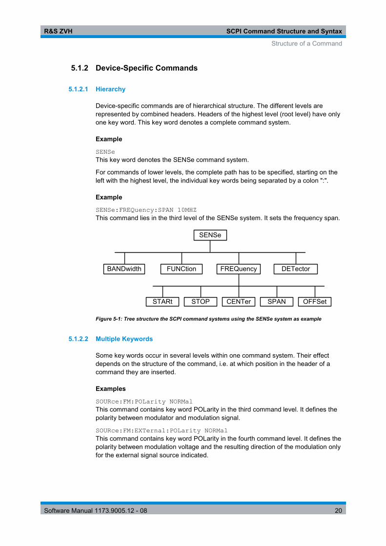
Device-specific commands are of hierarchical structure. The different levels are represented by combined headers. Headers of the highest level (root level) have only one key word. This key word denotes a complete command system.
Example
SENSe This key word denotes the SENSe command system.
For commands of lower levels, the complete path has to be specified, starting on the left with the highest level, the individual key words being separated by a colon ":".
Example
SENSe:FREQuency:SPAN 10MHZ This command lies in the third level of the SENSe system. It sets the frequency span.
SENSe
BANDwidth FUNCtion FREQuency DETector
STARt STOP CENTer SPAN OFFSet
Figure 5-1: Tree structure the SCPI command systems using the SENSe system as example
5.1.2.2 Multiple Keywords
Some key words occur in several levels within one command system. Their effect depends on the structure of the command, i.e. at which position in the header of a command they are inserted.
Examples
SOURce:FM:POLarity NORMal This command contains key word POLarity in the third command level. It defines the polarity between modulator and modulation signal.
SOURce:FM:EXTernal:POLarity NORMal This command contains key word POLarity in the fourth command level. It defines the polarity between modulation voltage and the resulting direction of the modulation only for the external signal source indicated.

R&S ZVH SCPI Command Structure and Syntax
Structure of a Command
Software Manual 1173.9005.12 - 08 21
5.1.2.3 Optional Keywords
Some command systems permit certain key words to be inserted into the header or omitted. These key words are marked by square brackets in the description. The full command length must be recognized by the instrument for reasons of compatibility with the SCPI standard. Some commands are considerably shortened by these optional key words.
Example
[SENSe]:BANDwidth[:RESolution]:AUTO This command couples the resolution bandwidth of the instrument to other parameters. The following command has the same effect: BANDwidth:AUTO
Optional keywords with numeric suffixes Do not omit an optional keyword if it includes a numeric suffix that is relevant for the effect of the command.
Example
DISPlay[:WINDow<1...4>]:MAXimize <Boolean> Command DISP:MAX ON refers to window 1. In order to refer to a window other than 1, you must include the optional WINDow parameter with the suffix for the required window. DISP:WIND2:MAX ON refers to window 2.
5.1.2.4 Long and Short Form
The key words feature a long form and a short form. Either the short form or the long form can be entered, other abbreviations are not permitted.
Example
STATus:QUEStionable:ENABle 1 is equivalent to STAT:QUES:ENAB 1
Upper and lower case notation of commands Upper-case and lower-case notation only serves to distinguish the two forms in the manual, the instrument itself does not distinguish upper-case and lower-case letters.

R&S ZVH SCPI Command Structure and Syntax
Structure of a Command
Software Manual 1173.9005.12 - 08 22
5.1.2.5 Parameter
The parameter must be separated from the header by a "white space". If several parameters are specified in a command, they are separated by a comma ",". A few queries permit the parameters MINimum, MAXimum and DEFault to be entered. Refer to "Parameters" for a detailed description of the various parameters.
Example
SENSe:FREQuency:STOP? MAXimum Response: 3.5E9 This query requests the maximal value for the stop frequency.
5.1.2.6 Special Characters
| A vertical stroke in parameter definitions indicates alternative possibilities in the sense of "or". The effect of the command differs, depending on which parameter is used.
Example
DISPlay:FORMat SINGle | SPLit If parameter SINGle is selected, full screen is displayed, in the case of SPLit, split screen is displayed.
A selection of key words with an identical effect exists for several commands. These keywords are indicated in the same line; they are separated by a vertical stroke. Only one of these keywords needs to be included in the header of the command. The effect of the command is independent of which of the keywords is used.
Example
SENSe:BANDwidth|BWIDth[:RESolution] The two following commands with identical meaning can be created. They set the frequency of the fixed frequency signal to 1 kHz: SENSe:BAND 1 SENSe:BWID 1
[ ] Key words in square brackets can be omitted when composing the header. The full command length must be accepted by the instrument for reasons of compatibility with the SCPI standards.
Example
[SENSe:]BANDwidth|BWIDth[:RESolution] SENS:BAND:RES is equivalent to BAND
Parameters in square brackets can be incorporated optionally in the command or omitted as well.

R&S ZVH SCPI Command Structure and Syntax
Structure of a Command
Software Manual 1173.9005.12 - 08 23
Example
MMEMory:NETWork:MAP <string>,<string>[,string>,<string>,<boolean>]
Entries in square brackets are optional or can be omitted.
{ } Parameters in curly brackets are optional and can be inserted once or several times, or omitted.
Example
SENSe:LIST:FREQuency <numeric_value>{,<numeric_value>}
The following are valid commands: SENS:LIST:FREQ 10 SENS:LIST:FREQ 10,20 SENS:LIST:FREQ 10,20,30,40
5.1.2.7 Numeric Suffix
If a device features several functions or features of the same kind, e.g. inputs, the desired function can be selected by a suffix added to the command. Entries without suffix are interpreted like entries with the suffix 1. Optional keywords must be specified if they select a function with the suffix.
Example
SYSTem:COMMunicate:SERial2:BAUD 9600 This command sets the baud rate of a second serial interface.
Suffix counting In case of remote control, suffix counting may differ from the numbers of the corresponding selection used in manual operation. SCPI prescribes that suffix counting starts with 1. Suffix 1 is the default state and used when no specific suffix is specified. Some standards define a fixed numbering, starting with 0. With GSM, for instance, slots are counted from 0 to 7. In the case of remote control, the slots are selected with the suffixes 1 to 8. If the numbering differs in manual operation and remote control, it is indicated with the respective command.

R&S ZVH SCPI Command Structure and Syntax
Structure of a Command
Software Manual 1173.9005.12 - 08 24
5.1.3 Overview of Syntax Elements
The following table offers an overview of the syntax elements.
: The colon separates the key words of a command. In a program message the separating semicolon marks the uppermost command level.
; The semicolon separates two commands within a program message. It does not alter the path.
, The comma separates several parameters of a command.
? The question mark forms a query.
* The asterisk marks a common command.
" Quotation marks introduce a string and terminate it.
# The hash symbol # introduces binary, octal, hexadecimal and block data.
● Binary: #B10110
● Octal: #O7612
● Hexa: #HF3A7
● Block: #21312
A "white space" (ASCII-Code 0 to 9, 11 to 32 decimal, e.g. blank) separates header and parameter.
R&S ZVH SCPI Command Structure and Syntax
Parameters
Software Manual 1173.9005.12 - 08 25
5.2 Parameters
For most commands a parameter needs to be supplemented. The parameter has to be separated from the header by a "white space". Possible parameters are:
● Numeric values ● Special numeric values ● Boolean parameters ● Text ● Character strings ● Block data.
The type of parameter required for each command and the allowed range of values are specified in the command description.
5.2.1 Numeric Values
Numeric values can be entered in any form, i.e. with sign, decimal point and exponent. Values exceeding the resolution of the instrument are rounded up or down. The mantissa may comprise up to 255 characters, the exponent must lie inside the value range -32000 to 32000. The exponent is introduced by an "E" or "e". Entry of the exponent alone is not permissible. In the case of physical quantities, the unit can be entered. Permissible unit prefixes are G (giga), MA (mega), MOHM and MHZ are also possible), K (kilo), M (milli), U (micro) and N (nano). If the unit is missing, the basic unit is used.
Example
SENSe:FREQuency:STOP 1.5GHz = SENSe:FREQuency:STOP 1.5E9

R&S ZVH SCPI Command Structure and Syntax
Parameters
Software Manual 1173.9005.12 - 08 26
5.2.2 Special Numeric Values
The texts MINimum, MAXimum, DEFault, UP and DOWN are interpreted as special numeric values. In case of a query, the numeric value is returned.
● MIN/MAX
MINimum and MAXimum denote the minimum and maximum value.
● DEF
DEFault denotes a preset value which has been stored in the EPROM. This value conforms to the default setting, as it is called by the *RST command
● UP/DOWN
UP, DOWN increases or reduces the numerical value by one step. The step width can be specified via an allocated step command for each parameter which can be set via UP, DOWN.
● INF/NINF
INFinity, Negative INFinity (NINF) Negative INFinity (NINF) represent the numerical values -9.9E37 or 9.9E37, respectively. INF and NINF are only sent as device reponses.
● NAN
Not A Number (NAN) represents the value 9.91E37. NAN is only sent as device response. This value is not defined. Possible causes are the division of zero by zero, the subtraction of infinite from infinite and the representation of missing values.
Example:
Setting command: SENSe:FREQuency:STOP MAXimum
Query: SENSe:FREQuency:STOP?, Response: 3.5E9
5.2.3 Boolean Parameters
Boolean parameters represent two states. The ON state (logically true) is represented by ON or a numerical value unequal to 0. The OFF state (logically untrue) is represented by OFF or the numerical value 0. The numerical values are provided as response for query.
Example
Setting command: CALCulate:MARKer:STATe ON
Query: CALCulate:MARKer:STATe?, Response: 1

R&S ZVH SCPI Command Structure and Syntax
Parameters
Software Manual 1173.9005.12 - 08 27
5.2.4 Text
Text parameters observe the syntactic rules for key words, i.e. they can be entered using a short or long form. Like any parameter, they have to be separated from the header by a white space. In the case of a query, the short form of the text is provided.
Example
Setting command: INPut:COUPling GROund
Query: INPut:COUPling?, Response: GRO
5.2.5 Strings
Strings must always be entered in quotation marks (' or ").
Example
SYSTem:LANGuage "SCPI" or SYSTem:LANGuage 'SCPI'
5.2.6 Block Data
Block data are a transmission format which is suitable for the transmission of large amounts of data. A command using a block data parameter has the following structure:
Example
HEADer:HEADer #45168xxxxxxxx
ASCII character # introduces the data block. The next number indicates how many of the following digits describe the length of the data block. In the example the 4 following digits indicate the length to be 5168 bytes. The data bytes follow. During the transmission of these data bytes all end or other control signs are ignored until all bytes are transmitted.

R&S ZVH SCPI Command Structure and Syntax
Structure of a Program Message
Software Manual 1173.9005.12 - 08 28
5.3 Structure of a Program Message
A program message may consist of one or several commands. It is terminated by the program message terminator which is the NL (New Line) charcter for LAN and USB connections.
Several commands in a program message must be separated by a semicolon ";". If the next command belongs to a different command system, the semicolon is followed by a colon. A colon ":" at the beginning of a command marks the root node of the command tree.
Example:
CALL InstrWrite(analyzer, "SENSe:FREQuency:CENTer 100MHz;:INPut:ATTenuation 10")
This program message contains two commands. The first one is part of the SENSe command system and is used to determine the center frequency of the instrument. The second one is part of the INPut command system and sets the input signal attenuation.
If the successive commands belong to the same system, having one or several levels in common, the program message can be abbreviated. For that purpose, the second command after the semicolon starts with the level that lies below the common levels (see also Fig. 1-1). The colon following the semicolon must be omitted in this case.
Example:
CALL InstrWrite(analyzer, "SENSe:FREQuency:STARt 1E6;:SENSe:FREQuency:STOP 1E9")
This program message is represented in its full length and contains two commands separated from each other by the semicolon. Both commands are part of the SENSe command system, subsystem FREQuency, i.e. they have two common levels.
When abbreviating the program message, the second command begins with the level below SENSe:FREQuency. The colon after the semicolon is omitted. The abbreviated form of the program message reads as follows:
CALL InstrWrite(analyzer, "SENSe:FREQuency:STARt 1E6;STOP 1E9")
However, a new program message always begins with the complete path.
Example:
CALL InstrWrite(analyzer, "SENSe:FREQuency:STARt 1E6") CALL InstrWrite(analyzer, "SENSe:FREQuency:STOP 1E9")

R&S ZVH SCPI Command Structure and Syntax
Responses to Queries
Software Manual 1173.9005.12 - 08 29
5.4 Responses to Queries
A query is defined for each setting command unless explicitly specified otherwise. It is formed by adding a question mark to the associated setting command. According to SCPI, the responses to queries are partly subject to stricter rules than in standard IEEE 488.2.
● The requested parameter is transmitted without header.
Example
INPut:COUPling? Response: DC
● Maximum values, minimum values and all further quantities, which are requested via a special text parameter are returned as numerical values.
Example
SENSe:FREQuency:STOP? MAX Response: 3.5E9
● Numerical values are output without a unit. Physical quantities are referred to the basic units or to the units set using the Unit command.
Example
SENSe:FREQuency:CENTer? Response: 1E6 (for 1 MHz)
● Truth values <Boolean values> are returned as 0 (for OFF) and 1 (for ON).
Example
SENSe:BANDwidth:AUTO? Response: 1 (for ON)
● Text (character data) is returned in a short form.
Example
SYSTem:COMMunicate:SERial:CONTrol:RTS? Response STAN (for standard)

R&S ZVH Command Sequence and Command Synchronization
Responses to Queries
Software Manual 1173.9005.12 - 08 30
6 Command Sequence and Command Synchronization What has been said above makes clear that all commands can potentially be carried out overlapping. In order to prevent an overlapping execution of commands, one of the commands *OPC, *OPC? or *WAI must be used. All three commands cause a certain action only to be carried out after the hardware has been set. By suitable programming, the controller can be forced to wait for the respective action to occur. For more information see Table 6-1.
Table 6-1: Synchronization using *OPC, *OPC? and *WAI
Command Action Programming the controller
*OPC Sets the Operation Complete bit in the ESR after all previous commands have been executed.
− Setting bit 0 in the ESE − Setting bit 5 in the SRE
− Waiting for service request (SRQ)
*OPC? Stops command processing until 1 is returned. This is only the case after the Operation Complete bit has been set in the ESR. This bit indicates that the previous setting has been completed.
Sending *OPC? directly after the command whose processing should be terminated before other commands can be executed.
*WAI Stops further command processing until all commands sent before *WAI have been executed.
Sending *WAI directly after the command whose processing should be terminated before other commands are executed.
For a couple of commands the synchronization to the end of command execution is mandatory in order to obtain the desired result. The affected commands require either more than one measurement in order to accomplish the desired instrument setting (e.g. auto range functions), or they require a longer period of time for execution. If a new command is received during execution of the corresponding function this may either lead to either to an aborted measurement or to incorrect measurement data.
The following list includes the commands, for which a synchronization via *OPC, *OPC? or *WAI is mandatory:
Table 6-2: Commands with mandatory synchronization (overlapping commands)
Command Purpose
INIT start measurement (sweep)
INIT:CONT OFF Set to single sweep
CALC:MARK:FUNC:xx? All Marker function queries

R&S ZVH Remote Control – Commands
Responses to Queries
Software Manual 1173.9005.12 - 08 31
7 Remote Control – Commands The following chapters provide a detailed description of all remote control commands currently available for the R&S ZVH and its firmware options.
Each section describes the commands for one of the operating modes available in the R&S ZVH, beginning with the description of common commands required to operate the instrument. The structure is based on that of the operating manual.
● Common Commands on page 32 ● Remote Commands of the Cable and Antenna Analyzer on page 35 ● Remote Commands of the Spectrum Analyzer on page 74 ● Remote Commands of the Network Analyzer Mode on page 142 ● Remote Commands of the Power Meter on page 163
Each section is subdivided into various tasks required to perform measurements with the R&S ZVH, also based on the structure of the operating manual. Some commands like those for controlling markers or configuring the frequency axis are available for all operating modes. In that case you will find a list of these commands in the corresponding section. However, a detailed description is provided only in the CAT commands section.
Availability of commands The cable and antenna test mode is implemented in the basic unit. For the other modes, the corresponding options are required.
Following the remote control commands required to perform specific measurements, you will find a description of general commands used to set up and control basic instrument functions. These commands are independent of the operating mode. Therefore they are listed separately.
● File Management on page 170 ● Making and Storing Screenshots on page 178 ● Configuring the Instrument on page 185 ● Remote Commands of the Status Reporting System on page 217
All chapters begin with a list of commands available in the context of that chapter. Following that list you will find a detailed description of all commands.
All individual descriptions contain:
● the complete notation and syntax of the command ● the description of the effects of the command ● a list of all parameters available for that command or the type of data the command
returns in case of query commands ● an example of how a program message would look like ● the *RST value ● information on SCPI conformity
An alphabetical list of all available commands is provided at the end of this manual.

R&S ZVH Remote Control – Commands
Common Commands
Software Manual 1173.9005.12 - 08 32
7.1 Common Commands
The common commands are taken from the IEEE 488.2 (IEC 625-2) standard. A particular command has the same effect on different devices. The headers of these commands consist of an asterisk "*" followed by three letters. Some of the common commands refer to the "Status Reporting System".
List of commands
● *CLS (p. 32) ● *ESE (p. 32) ● *ESR? (p. 32) ● *IDN? (p. 33) ● *IST? (p. 33) ● *OPC (p. 33) ● *OPT? (p. 33) ● *RST (p. 33) ● *SRE (p. 34) ● *STB? (p. 34) ● *TRG (p. 34) ● *TST? (p. 34) ● *WAI (p. 34)
*CLS
CLEAR STATUS sets the status byte (STB), the standard event register (ESR) and the EVENt part of the QUEStionable and the OPERation register to zero. The command does not alter the mask and transition parts of the registers. It clears the output buffer.
*ESE
EVENT STATUS ENABLE sets the event status enable register to the value indicated. The query form *ESE? returns the contents of the event status enable register in decimal form.
Parameter
0 to 255
*ESR?
STANDARD EVENT STATUS QUERY returns the contents of the event status register in decimal form (0 to 255) and subsequently sets the register to zero.
Parameter
0 to 255

R&S ZVH Remote Control – Commands
Common Commands
Software Manual 1173.9005.12 - 08 33
*IDN?
IDENTIFICATION QUERY queries the instrument identification.
Return values
<InstrumentName>,<SerialNumber/Model>,<FirmwareVersion>
Example for R&S ZVH: Rohde&Schwarz,ZVH4,100005/014,1.20
*IST?
INDIVIDUAL STATUS QUERY returns the contents of the IST flag in decimal form. The IST flag is the status bit which is sent during a parallel poll.
Parameter
0 | 1
*OPC
OPERATION COMPLETE sets bit 0 in the event status register after all preceding commands have been executed. This bit can be used to initiate a service request.
*OPT?
OPTION IDENTIFICATION QUERY queries the options included in the instrument and returns a list of the options installed. The options are separated from each other by means of commas.
Parameter
K<number> software options
For a list of all available options and their description refer to the CD-ROM.
Example
K40, K41, K42, K45
*RST
RESET sets the instrument to a defined default status. The command essentially corresponds to pressing the PRESET key.

R&S ZVH Remote Control – Commands
Common Commands
Software Manual 1173.9005.12 - 08 34
*SRE
SERVICE REQUEST ENABLE sets the service request enable register to the indicated value. Bit 6 (MSS mask bit) remains 0. This command determines under which conditions a service request is generated. The query form *SRE? reads the contents of the service request enable register in decimal form. Bit 6 is always 0.
Parameter
0 to 255
*STB?
READ STATUS BYTE QUERY reads out the contents of the status byte in decimal form.
*TRG
TRIGGER initiates all actions in the currently active test screen expecting a trigger event. This command corresponds to INITiate[:IMMediate].
*TST?
SELF TEST QUERY initiates the self test of the instrument and outputs an error code in decimal form.
Parameter
0 = no error
*WAI
WAIT TO CONTINUE permits servicing of subsequent commands only after all preceding commands have been executed and all signals have settled.

R&S ZVH Remote Control – Commands
Remote Commands of the Cable and Antenna Analyzer
Software Manual 1173.9005.12 - 08 35
7.2 Remote Commands of the Cable and Antenna Analyzer
This section provides a detailed description of all remote control commands required to configure and perform measurements in Cable and Antenna Test (CAT) mode.
Contents
Configuring the Horizontal Axis on page 36 Configuring the Vertical Axis on page 41 Setting the Bandwidth on page 47 Performing and Triggering Measurements on page 48 Working with Traces on page 50 Using Markers on page 54 Configuring and Using Measurement Functions on page 64

R&S ZVH Remote Control – Commands
Remote Commands of the Cable and Antenna Analyzer
Software Manual 1173.9005.12 - 08 36
7.2.1 Configuring the Horizontal Axis
The following commands configure the horizontal axis of the active display.
Commands independent of the operating mode Note that some of the commands for configuring the horizontal axis are also valid for other operating modes. If a command is available in another mode, it is indicated by the list in the respective section.
List of commands
● [SENSe:]FREQuency:CENTer <Frequency> (p. 36) ● [SENSe:]FREQuency:CENTer:STEP <StepSize> (p. 36) ● [SENSe:]FREQuency:CENTer:STEP:LINK <StepSizeCoupling> (p. 37) ● [SENSe:]FREQuency:SPAN <Span> (p. 38) ● [SENSe:]FREQuency:SPAN:AUTO <State> (p. 38) ● [SENSe:]FREQuency:STARt <StartFrequency> (p. 39) ● [SENSe:]FREQuency:STOP <StopFrequency> (p. 39) ● CALCulate:DTF:DISTance:STARt <StartDistance> (p. 39) ● CALCulate:DTF:DISTance:STOP <StopDistance> (p. 40)
[SENSe:]FREQuency:CENTer <Frequency>
This command defines the center frequency of the R&S ZVH.
In spectrum analyzer mode, the command also defines the measuring frequency for time domain measurements (span = 0).
Parameter
<Frequency> Numeric value in Hz.
The range depends on the operating mode and is specified in the data sheet.
Example
FREQ:CENT 100MHz Defines a center frequency of 100 MHz.
Characteristics
*RST value: fmax /2 with fmax = maximum frequency SCPI: conform
[SENSe:]FREQuency:CENTer:STEP <StepSize>
This command defines the center frequency step size.
Parameter
<StepSize> Numeric value in Hz.

R&S ZVH Remote Control – Commands
Remote Commands of the Cable and Antenna Analyzer
Software Manual 1173.9005.12 - 08 37
The range is from 1 Hz to fmax.
Example
FREQ:CENT:STEP 120MHz Defines a CF step size of 120 MHz.
Characteristics
*RST value: – (AUTO 0.1*SPAN is switched on) SCPI: conform
[SENSe:]FREQuency:CENTer:STEP:LINK <StepSizeCoupling>
This command couples and decouples the center frequency step size to the span.
For time domain measurements, the command couples the step size to the resolution bandwidth.
Parameter
<StepSizeCoupling>
DIVTen Couples the step size to 10 % of the span.
OFF Turns the coupling off (manual definition of the step size).
Example
FREQ:CENT:STEP:LINK DIVT Couples the step size to 10% of the span.
Characteristics
*RST value: DIVTen SCPI: device-specific
[SENSe:]FREQuency:SETTings:COUPling:ENABle <State>
This command couples and decouples frequency and span settings between the DTF measurement and the other measurements available in the Antenna & Cable Test mode.
Parameter
<State>
ON Frequency and span settings are coupled.
Settings are adapted when you switch between measurements.
OFF Frequency and span settings are decoupled.
DTF measurement has its own frequency and span settings compared to the other measurements..

R&S ZVH Remote Control – Commands
Remote Commands of the Cable and Antenna Analyzer
Software Manual 1173.9005.12 - 08 38
Example
FREQ:SETT:COUP:ENAB ON Couples the frequency and span settings.
Characteristics
*RST value: OFF SCPI: device-specific
[SENSe:]FREQuency:SPAN <Span>
This command defines the frequency span.
If you set a span of 0 Hz in spectrum mode, the R&S ZVH starts a measurement in the time domain.
Parameter
<Span> Numeric value in Hz. The value range is specified in the data sheet.
Example
FREQ:SPAN 10MHz Defines a span of 10 MHz.
Characteristics
*RST value: fmax with fmax = maximum frequency SCPI: conform
[SENSe:]FREQuency:SPAN:AUTO <State>
This command turns the automatic calculation of the ideal span on and off.
Parameter
<State> ON | OFF
Example
FREQ:SPAN:AUTO ON Turns automatic span determination on and off.
Characteristics
*RST value: OFF SCPI: device-specific

R&S ZVH Remote Control – Commands
Remote Commands of the Cable and Antenna Analyzer
Software Manual 1173.9005.12 - 08 39
[SENSe:]FREQuency:STARt <StartFrequency>
This command defines the start frequency for measurements in the frequency domain (span > 0).
Parameter
<StartFrequency> Numeric value in Hz.
The range depends on the operating mode and is specified in the datasheet.
Example
FREQ:STAR 20MHz Defines a start frequency of 20 MHz.
Characteristics
*RST value: 0 SCPI: conform
[SENSe:]FREQuency:STOP <StopFrequency>
This command defines the stop frequency for measurements in the frequency domain (span > 0).
Parameter
<StopFrequency> Numeric value in Hz.
The range depends on the operating mode and is specified in the datasheet.
Example
FREQ:STOP 2000MHz Defines a stop frequency of 2 GHz
Characteristics
*RST value: fmax SCPI: conform
CALCulate:DTF:DISTance:STARt <StartDistance>
This command defines the start distance of the cable measurement.
Parameter
<StartDistance> Numeric value in the range from 3 m (10 ft) to 1500 m (4921 ft)
The unit is either meter or feet, depending on your selection.
Example
CALC:DTF:DIST:STAR 50m Sets the starting point of the measurement to 50 m.

R&S ZVH Remote Control – Commands
Remote Commands of the Cable and Antenna Analyzer
Software Manual 1173.9005.12 - 08 40
Characteristics
*RST value: 3 m (10 ft) SCPI: device-specific
CALCulate:DTF:DISTance:STOP <StopDistance>
This command defines the end point of the cable measurement.
Parameter
<StopDistance> numeric value in the range from 3 m (10 ft) to 1500 m (4921 ft)
The unit is either meter or feet, depending on your selection.
Example
CALC:DTF:DIST:STAR 500m Sets the end point of the measurement to 500 m.
Characteristics
*RST value: 1500 m (4921 ft) SCPI: device-specific

R&S ZVH Remote Control – Commands
Remote Commands of the Cable and Antenna Analyzer
Software Manual 1173.9005.12 - 08 41
7.2.2 Configuring the Vertical Axis
The following commands configure the vertical axis of the active display.
Commands independent of the operating mode Note that some of the commands for configuring the vertical axis are also valid for other operating modes. If a command is available in another mode, it is indicated by the list in the respective section.
List of commands
● DISPlay[:WINDow]:TRACe<t>:Y[:SCALe]:ADJust (p. 41) ● DISPlay<n>:LOSS:REFerence <RefValue> (p. 41) ● DISPlay<n>:LOSS:REFerence:POSition <RefPosition> (p. 42) ● DISPlay<n>:LOSS:Y:SCALe <DisplayRange> (p. 42) ● DISPlay<n>:MAGNitude:REFerence <RefValue> (p. 43) ● DISPlay<n>:MAGNitude:REFerence:POSition <RefPosition> (p. 43) ● DISPlay<n>:MAGNitude:Y:SCALe <DisplayRange> (p. 43) ● DISPlay<n>:MAGNitude:Y:SPACing <Scaling> (p. 44) ● DISPlay<n>:VSWR:Y:SCALe:MINimum <BottomValue> (p. 44) ● DISPlay<n>:VSWR:Y:SCALe:MAXimum <TopValue> (p. 45) ● DISPlay<n>:VSWR:Y:SCALe <DisplayRange> (p. 45) ● INPut:ATTenuation <Attenuation> (p 45) ● SOURce:TG:ATTenuation <TGAttenuation> (p. 46)
DISPlay[:WINDow]:TRACe<t>:Y[:SCALe]:ADJust
This command automatically scales the vertical axis for ideal display results.
This command is an event and therefore has no query and no *RST value.
Example
DISP:TRAC:Y:ADJ Determines the ideal scaling for the y-axis.
Characteristics
*RST value: - SCPI: device-specific
DISPlay:LOSS:REFerence <RefValue>
This command defines the reference value for the cable loss measurement format.
Parameter
<RefValue> Numeric value in the range from -100 dB to 100 dB.

R&S ZVH Remote Control – Commands
Remote Commands of the Cable and Antenna Analyzer
Software Manual 1173.9005.12 - 08 42
Example
DISP:LOSS:REF 10 Defines a reference level of 10 dB.
Characteristics
*RST value: 0 dB SCPI: device-specific
DISPlay:LOSS:REFerence:POSition <RefPosition>
This command defines the position of the reference value in the diagram for the cable loss measurement format.
Each step shifts the reference position one grid line up or down.
Parameter
<RefPosition> Numeric value in the range from 0 to 10.
Example
DISP:LOSS:REF:POS 5 Moves the reference to the fifth grid line from the bottom.
Characteristics
*RST value: 10 SCPI: device-specific
DISPlay:LOSS:Y:SCALe <DisplayRange>
This command defines the display range of the vertical axis for the cable loss measurement format.
Parameter
<DisplayRange> Numeric value in the range from 1 dB to 100 dB.
Example
DISP:LOSS:Y:SCAL 20 Defines a display range of 20 dB
Characteristics
*RST value: 100 dB SCPI: device-specific

R&S ZVH Remote Control – Commands
Remote Commands of the Cable and Antenna Analyzer
Software Manual 1173.9005.12 - 08 43
DISPlay:MAGNitude:REFerence <RefValue>
This command defines the reference value for the magnitude measurement format.
Parameter
<RefValue> Numeric value in the range from -80 dB to 30 dB
Example
DISP:MAGN:REF -10 Defines a reference level of -10 dB
Characteristics
*RST value: 0 dB SCPI: device-specific
DISPlay:MAGNitude:REFerence:POSition <RefPosition>
This command defines the position of the reference value in the diagram for the magnitude measurement format.
Each step shifts the reference position one grid line up or down.
Parameter
<RefPosition> Numeric value in the range from 0 to 10.
Example
DISP:MAGN:REF:POS 5 Moves the reference to the fifth grid line from the bottom.
Characteristics
*RST value: 10 SCPI: device-specific
DISPlay:MAGNitude:Y:SCALe <DisplayRange>
This command defines the display range of the vertical axis for the magnitude measurement format.
Note that you have to set a logarithmic scaling before you can use this command with DISPlay<n>:MAGNitude:Y:SPACing <Scaling>.
Parameter
<DisplayRange> Numeric value in the range from 1 dB to 150 dB.
The number you enter is rounded up to the next possible display range. For example, if you enter 9, the R&S ZVH automatically sets the display range to 10.

R&S ZVH Remote Control – Commands
Remote Commands of the Cable and Antenna Analyzer
Software Manual 1173.9005.12 - 08 44
Example
DISP:MAGN:Y:SCAL 50 DB Defines a display range of 50 dB.
Characteristics
*RST value: 100 dB SCPI: device-specific
DISPlay:MAGNitude:Y:SPACing <Scaling>
This command selects the scaling of the vertical axis for the magnitude measurement format.
Parameter
<Scaling>
LOGarithmic Selects a logarithmic scale (dB).
LINear Selects a linear scale (%).
Example
DISP:MAGN:Y:SPAC LIN Selects linear scaling.
Characteristics
*RST value: LOGarithmic SCPI: device-specific
DISPlay<n>:VSWR:Y:SCALe:MINimum <BottomValue>
This command defines the bottom value of the vertical axis for the VSWR measurement format.
Parameter
<BottomValue> Numeric value in the range from 1.0 to 70.
Example
DISP:VSWR:Y:SCAL:MIN 3 Defines a bottom value of 3 for the vertical axis.
Characteristics
*RST value: 1.0 SCPI: device-specific

R&S ZVH Remote Control – Commands
Remote Commands of the Cable and Antenna Analyzer
Software Manual 1173.9005.12 - 08 45
DISPlay<n>:VSWR:Y:SCALe:MAXimum <TopValue>
This command defines the top value of the vertical axis for the VSWR measurement format.
Parameter
<TopValue> Numeric value in the range from 1.1 to 71.
Example
DISP:VSWR:Y:SCAL:MAX 25 Defines a top value of 25 for the vertical axis.
Characteristics
*RST value: 21 SCPI: device-specific
DISPlay:VSWR:Y:SCALe <DisplayRange>
This command defines the display range of the vertical axis for the VSWR measurement format.
Parameter
<DisplayRange> Numeric value in the range from 1.1 to 71.
The number you enter is rounded up to the next possible display range. For example, if you enter 5, the R&S ZVH automatically sets the display range to 1...6.
Example
DISP:VSWR:Y:SCAL 50 Defines a display range of 1...71.
Characteristics
*RST value: 1...21 SCPI: device-specific
INPut:ATTenuation <Attenuation>
This command defines the input attenuation.
In spectrum mode, the attenuation is coupled to the reference level. If you set the attenuation independently, the R&S ZVH turns off this coupling.
The R&S ZVH adjusts the reference level if it can not be set for the current RF attenuation.
Parameter
<Attenuation> Numeric value in in the range from 0 dB to 40 dB in 5 dB steps.

R&S ZVH Remote Control – Commands
Remote Commands of the Cable and Antenna Analyzer
Software Manual 1173.9005.12 - 08 46
Example
INP:ATT 30dB Defines an attenuation of 30 dB and deactivates coupling to the reference level.
Characteristics
*RST value: 0 dB (AUTO is ON) SCPI: conform
SOURce:TG:ATTenuation <TGAttenuation>
This command defines the output level of the tracking generator.
Parameter
<TGAttenuation> Numeric value in the range from 0 to 50 dB.
Entering an output level of, e.g., 20 dB results in an output level of -20 dBm.
Example
SOUR:TG:ATT 50 Defines the attenuation to 50 dB and therefore an output level of –50 dBm
Characteristics
*RST value: 0 dB SCPI: device-specific

R&S ZVH Remote Control – Commands
Remote Commands of the Cable and Antenna Analyzer
Software Manual 1173.9005.12 - 08 47
7.2.3 Setting the Bandwidth
The following commands configure the filter bandwidths of the R&S ZVH. Note that both groups of commands (BANDwidth and BWIDth) are the same.
List of commands
● [SENSe:]BANDwidth|BWIDth[:RESolution] <MeasBW> (p. 47) ● [SENSe:]BANDwidth|BWIDth[:RESolution]:AUTO <State> (p. 47)
[SENSe:]BANDwidth|BWIDth[:RESolution] <MeasBW>
This command defines the measurement bandwidth.
Analog resolution filters of 100 Hz to 100 kHz in 1 - 3 - 10 steps are available.
Parameter
<MeasBW> Numeric value in the range from 100 Hz to 100 kHz.
Example
BAND 100 kHz Sets the bandwidth to 100 kHz
Characteristics
*RST value: – (AUTO is set to ON) SCPI: conform
[SENSe:]BANDwidth|BWIDth[:RESolution]:AUTO <State>
This command couples or decouples the measurement bandwidth to the span.
Parameter
<State> ON | OFF
Example
BAND:AUTO OFF Switches off the coupling of the resolution bandwidth to the span.
Characteristics
*RST value: ON SCPI: conform

R&S ZVH Remote Control – Commands
Remote Commands of the Cable and Antenna Analyzer
Software Manual 1173.9005.12 - 08 48
7.2.4 Performing and Triggering Measurements
7.2.4.1 Performing the Measurement
The following commands configure the sweep.
List of commands
● INITiate:CONTinuous <SweepMode> (p. 89) ● SENSe:SWEep:POINts <Points> (p. 48)
For a detailed description of commands refer to "Performing and Triggering Measurements" in spectrum analyzer mode.
SENSe:SWEep:POINts <Points>
This command selects the number of measurement points.
Parameter
<Points> 101 | 201 | 401 | 601 | 631 | 801 | 1001 | 1201
Example
SWE:POIN 101 Defines 101 measurement points.
Characteristics
*RST value: 201 SCPI: conform
7.2.4.2 Triggering Measurements
The following commands set up trigger conditions if you are using a trigger for the measurement.
List of commands
● TRIGger[:SEQuence]:HOLDoff[:TIME] <TriggerDelay> (p. 48) ● TRIGger[:SEQuence]:SLOPe <TriggerSlope> (p. 49) ● TRIGger[:SEQuence]:SOURce <TriggerSource> (p. 49)
TRIGger[:SEQuence]:HOLDoff[:TIME] <TriggerDelay>
This command defines the length of the trigger delay.
Parameter
<TriggerDelay> Numeric value in the range from 0 s to 100 s.

R&S ZVH Remote Control – Commands
Remote Commands of the Cable and Antenna Analyzer
Software Manual 1173.9005.12 - 08 49
Example
TRIG:HOLD 500us Defines a trigger delay of 500 µs.
Characteristics
*RST value: 0 s SCPI: conform
TRIGger[:SEQuence]:SLOPe <TriggerSlope>
This command selects the slope of the trigger signal.
The trigger slope affects all trigger sources.
Parameter
<TriggerSlope> POSitive | NEGative
Example
TRIG:SLOP NEG Selects a negative trigger slope.
Characteristics
*RST value: POSitive SCPI: conform
TRIGger[:SEQuence]:SOURce <TriggerSource>
This command selects the trigger source that initiates a measurement.
Parameter
<TriggerSource>
IMMediate Free Run measurements.
EXTernal External triggering.
For more information see R&S ZVH operating manual chapter "Setting the Sweep"
Example
TRIG:SOUR EXT Selects the external trigger input as source of the trigger signal
Characteristics
*RST value: IMMediate SCPI: conform

R&S ZVH Remote Control – Commands
Remote Commands of the Cable and Antenna Analyzer
Software Manual 1173.9005.12 - 08 50
7.2.5 Working with Traces
The following commands set up the trace and the various functions associated with it, e.g. trace mathematics or the selection of the detector.
The suffix <t> at TRACe and MATH selects the trace the command works on.
List of commands
● CALCulate:MATH<t>:COPY:MEMory (p. 50) ● DISPlay[:WINDow]:TRACe<t>:MEMory[:STATe] <State> (p. 50) ● DISPlay[:WINDow]:TRACe<t>:MODE <TraceMode> (p. 51) ● FORMat[:DATA] <DataFormat> (p. 51) ● MEASurement:ISUP <State> (p. 52) ● MEASurement:ISUP:APER <Aperture> (p. 52) ● TRACe<t>:DATA (p. 52) ● UNIT:LENGth <Unit> (p. 53)
CALCulate:MATH<t>:COPY:MEMory
This command copies the current trace into the memory of the R&S ZVH.
This command is an event and therefore has no query and no *RST value.
Example
CALC:MATH:COPY:MEM Copies the trace into the memory.
Characteristics
*RST value: - SCPI: device-specific
DISPlay[:WINDow]:TRACe<t>:MEMory[:STATe] <State>
This command turns the memory trace on and off.
Parameter
<State> ON | OFF
Example
DISP:TRAC:MEM ON Turns on the memory trace.
Characteristics
*RST value: OFF SCPI: device-specific

R&S ZVH Remote Control – Commands
Remote Commands of the Cable and Antenna Analyzer
Software Manual 1173.9005.12 - 08 51
DISPlay[:WINDow]:TRACe<t>:MODE <TraceMode>
This command selects the trace mode.
If you are using the average, max hold or min hold trace mode, you can set the number of measurements with [SENSe:]SWEep:COUNt <SweepCount>. Note that synchronization to the end of the average count is possible only in single sweep mode.
Parameter
<TraceMode> AVERage | MAXHold | MINHold | VIEW | WRITe
Example
SWE:CONT OFF SWE:COUN 16 Turn on single sweep mode and defines a sweep count of 16 measurements.
DISP:TRAC:MODE MAXH Activates MAXHold mode for the trace.
INIT;*WAI Performs a measurement with synchronization after 16 sweeps.
Characteristics
*RST value: WRITe SCPI: device–specific
FORMat[:DATA] <DataFormat>
This command selects the data format that is used for transmission of trace data from the R&S ZVH to the controlling computer.
Note that the command has no effect for data that you send to the R&S ZVH. The R&S ZVH automatically recognizes the data it receives, regardless of the format.
Parameter
<DataFormat>
ASCii ASCII format, separated by commas.
REAL,32 32-bit IEEE 754 floating point numbers in the "definite length block format".
In REAL,32 format, a string of return values would look like: #42524<value 1><value 2>...<value n> with
#4 Number of digits of the following number of data bytes (= 4 in this example)
2524 Number of following data bytes (2524, corresponds to the 631 sweep points of the R&S ZVH.
<value> 4-byte floating point value

R&S ZVH Remote Control – Commands
Remote Commands of the Cable and Antenna Analyzer
Software Manual 1173.9005.12 - 08 52
Example
FORM ASC Selects the ASCII data format.
Characteristics
*RST value: ASCii SCPI: conform
MEASurement:ISUP <State>
This command turns interference suppression on and off.
Parameter
<State> ON | OFF
Example
MEAS:ISUP ON Turns interference suppression on.
Characteristics
*RST value: OFF SCPI: device-specific
MEASurement:ISUP:APER <Aperture>
This command defines the aperture size for interference suppression.
Parameter
<Aperture> Numeric value that defines the aperture.
Example
MEAS:ISUP:APER 0.8 Sets an aperture of 0.8.
Characteristics
*RST value: 1 SCPI: device-specific
TRACe<t>:DATA <Destination>
This command queries the current trace data.
You can set the data format with the FORMat[:DATA] <DataFormat>.
Parameter
<Destination>

R&S ZVH Remote Control – Commands
Remote Commands of the Cable and Antenna Analyzer
Software Manual 1173.9005.12 - 08 53
TRACE1 Queries the data of trace 1.
TRACE2 Queries the data of trace 2..
Return value
The R&S ZVH returns 631 values. Each value corresponds to one pixel of a trace.
The result and unit depends on the measurement format.
Example
TRAC:DATA? TRACE1 Reads out the data for trace 1.
Characteristics
*RST value: - SCPI: conform
UNIT:LENGth <Unit>
This command selects the length unit.
Parameter
<Unit> METer | FEET
Example
UNIT:LENGth FEET Selects feet as the length unit.
Characteristics
*RST value: METer SCPI: conform
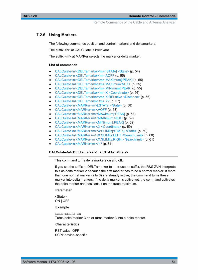
R&S ZVH Remote Control – Commands
Remote Commands of the Cable and Antenna Analyzer
Software Manual 1173.9005.12 - 08 54
7.2.6 Using Markers
The following commands position and control markers and deltamarkers.
The suffix <n> at CALCulate is irrelevant.
The suffix <m> at MARKer selects the marker or delta marker.
List of commands
● CALCulate<n>:DELTamarker<m>[:STATe] <State> (p. 54) ● CALCulate<n>:DELTamarker<m>:AOFF (p. 55) ● CALCulate<n>:DELTamarker<m>:MAXimum[:PEAK] (p. 55) ● CALCulate<n>:DELTamarker<m>:MAXimum:NEXT (p. 55) ● CALCulate<n>:DELTamarker<m>:MINimum[:PEAK] (p. 55) ● CALCulate<n>:DELTamarker<m>:X <Coordinate> (p. 56) ● CALCulate<n>:DELTamarker<m>:X:RELative <Distance> (p. 56) ● CALCulate<n>:DELTamarker<m>:Y? (p. 57) ● CALCulate<n>:MARKer<m>[:STATe] <State> (p. 58) ● CALCulate<n>:MARKer<m>:AOFF (p. 58) ● CALCulate<n>:MARKer<m>:MAXimum[:PEAK] (p. 58) ● CALCulate<n>:MARKer<m>:MAXimum:NEXT (p. 59) ● CALCulate<n>:MARKer<m>:MINimum[:PEAK] (p. 59) ● CALCulate<n>:MARKer<m>:X <Coordinate> (p. 59) ● CALCulate<n>:MARKer<m>:X:SLIMits[:STATe] <State> (p. 60) ● CALCulate<n>:MARKer<m>:X:SLIMits:LEFT <SearchLimit> (p. 60) ● CALCulate<n>:MARKer<m>:X:SLIMits:RIGHt <Searchlimit> (p. 61) ● CALCulate<n>:MARKer<m>:Y? (p. 61)
CALCulate<n>:DELTamarker<m>[:STATe] <State>
This command turns delta markers on and off.
If you set the suffix at DELTamarker to 1, or use no suffix, the R&S ZVH interprets this as delta marker 2 because the first marker has to be a normal marker. If more than one normal marker (2 to 6) are already active, the command turns these marker into delta markers. If no delta marker is active yet, the command activates the delta marker and positions it on the trace maximum.
Parameter
<State> ON | OFF
Example
CALC:DELT3 ON Turns delta marker 3 on or turns marker 3 into a delta marker.
Characteristics
RST value: OFF SCPI: device–specific
R&S ZVH Remote Control – Commands
Remote Commands of the Cable and Antenna Analyzer
Software Manual 1173.9005.12 - 08 55
CALCulate<n>:DELTamarker<m>:AOFF
This command turns off all active delta markers.
This command is an event and therefore has no query and no *RST value.
Example
CALC:DELT:AOFF Turns off all delta markers.
Characteristics
RST value: – SCPI: device–specific
CALCulate<n>:DELTamarker<m>:MAXimum[:PEAK]
This command positions a delta marker on the current trace maximum.
If necessary, the corresponding delta marker is activated first.
This command is an event and therefore has no *RST value and no query.
Example
CALC:DELT3:MAX Moves delta marker 3 to the maximum peak.
Characteristics
RST value: – SCPI: device–specific
CALCulate<n>:DELTamarker<m>:MAXimum:NEXT
This command positions a delta marker on the next smaller trace maximum.
If necessary, the corresponding delta marker is activated first.
This command is an event and therefore has no *RST value and no query.
Example
CALC:DELT2:MAX:NEXT Moves delta marker 2 to the next smaller maximum peak.
Characteristics
RST value: – SCPI: device–specific
CALCulate<n>:DELTamarker<m>:MINimum[:PEAK]
This command positions a delta marker on the current trace minimum.
If necessary, the corresponding delta marker is activated first.
This command is an event and therefore has no *RST value and no query.

R&S ZVH Remote Control – Commands
Remote Commands of the Cable and Antenna Analyzer
Software Manual 1173.9005.12 - 08 56
Example
CALC:DELT3:MIN Moves delta marker 3 to the trace minimum.
Characteristics
RST value: – SCPI: device–specific
CALCulate<n>:DELTamarker<m>:X <Coordinate>
This command positions a delta marker on a particular coordinate on the horizontal axis.
Note that it is possible to place the marker outside the visible trace. In that case, this value is invalid.
If necessary, the corresponding delta marker is activated first.
Parameter
<Coordinate> Numeric value that indicates the coordinate on the horizontal axis.
The range corresponds to the maximum span.
The unit depends on the measurement, e.g. Hz for measurements in the frequency domain and seconds for measurements in the time domain.
Example
CALC:DELT:MOD REL Delta marker positions are relative to marker 1.
CALC:DELT2:X 10.7MHz Positions delta marker 2 10.7 MHz to the right of marker 1.
CALC:DELT2:X? CALC:DELT2:X:REL? Queries the absolute and relative position of delta marker 2.
Characteristics
RST value: – SCPI: device–specific
CALCulate<n>:DELTamarker<m>:X:RELative <Distance>
This command positions a delta marker on a position relative to the reference marker.
If necessary, the corresponding delta marker is activated first.
Parameter
<Distance> Numeric value that defines the distance of the marker to the reference marker

R&S ZVH Remote Control – Commands
Remote Commands of the Cable and Antenna Analyzer
Software Manual 1173.9005.12 - 08 57
The range depends on the current scaling of the horizontal axis.
The unit depends on the measurement, e.g. Hz for measurements in the frequency domain and seconds for measurements in the time domain.
Example
CALC:DELT3:X:REL 5 kHz Sets the delta marker at a distance of 5 kHz to the reference position.
Characteristics
RST value: – SCPI: device–specific
CALCulate<n>:DELTamarker<m>:Y?
This command queries the vertical position of a delta marker. The result is always a relative value in relation to marker 1.
If necessary, the corresponding delta marker is activated first.
To get a valid result, you have to perform a complete sweep with synchronization to the sweep end between activating the delta marker and reading out the result. This is only possible in single sweep mode.
Return value
<MarkerPosition>
In NA and CAT mode, the unit depends on the measurement format.
In spectrum analyzer mode, the unit depends on the unit you have set and the scaling of the vertical axis.
Parameter or measuring functions Output unit
DBM | DBPW | DBUV | DBMV | DBUA dB (lin/log)
WATT | VOLT | AMPere dB (lin), % (log)
Example
INIT:CONT OFF Switches to single sweep mode.
CALC:DELT2 ON Switches on delta marker 2.
INIT;*WAI Starts a sweep and waits for its end.
CALC:DELT2:Y? Queries the horizontal position of delta marker 2.
Characteristics
RST value: – SCPI: device–specific

R&S ZVH Remote Control – Commands
Remote Commands of the Cable and Antenna Analyzer
Software Manual 1173.9005.12 - 08 58
CALCulate<n>:MARKer<m>[:STATe] <State>
This command turns markers on and off.
If you do not use a suffix at MARKer, marker 1 is selected. If one or more delta markers (2 to 6) are already active, the command turns these delta markers into normal markers.
Parameter
<State> ON | OFF
Example
CALC:MARK3 ON Turns on marker 3.
Characteristics
*RST value: OFF SCPI: device–specific
CALCulate<n>:MARKer<m>:AOFF
This command turns off all active markers, delta markers and active marker measurement functions.
This command is an event and therefore has no query and no *RST value.
Example
CALC:MARK:AOFF Turns off all markers.
Characteristics
*RST value: – SCPI: device–specific
CALCulate<n>:MARKer<m>:MAXimum[:PEAK]
This command positions a marker on the current trace maximum.
If necessary, the corresponding marker is activated first.
This command is an event and therefore has no *RST value and no query.
Example
CALC:MARK2:MAX Moves marker 2 to the maximum peak.
Characteristics
*RST value: – SCPI: device–specific

R&S ZVH Remote Control – Commands
Remote Commands of the Cable and Antenna Analyzer
Software Manual 1173.9005.12 - 08 59
CALCulate<n>:MARKer<m>:MAXimum:NEXT
This command positions a marker on the next smaller trace maximum.
If necessary, the corresponding marker is activated first.
This command is an event and therefore has no *RST value and no query.
Example
CALC:MARK2:MAX:NEXT Moves marker 2 to the next smaller maximum peak.
Characteristics
*RST value: – SCPI: device–specific
CALCulate<n>:MARKer<m>:MINimum[:PEAK]
This command positions a marker on the current trace minimum.
If necessary, the corresponding marker is activated first.
This command is an event and therefore has no *RST value and no query.
Example
CALC:MARK2:MIN Moves marker 2 to the trace minimum.
Characteristics
*RST value: – SCPI: device–specific
CALCulate<n>:MARKer<m>:X <Coordinate>
This command positions a marker on a particular coordinate on the horizontal axis.
If one or more delta markers (2 to 6) are already active, the command turns these delta markers into normal markers.
Note that it is possible to place the marker outside the visible trace. In that case, this value is invalid.
If necessary, the corresponding delta marker is activated first.
Parameter
<Coordinate> Numeric value indicating the coordinate on the horizontal axis.
The range corresponds to the maximum span.
The unit in spectrum analyzer mode depends on the measurement, e.g. Hz for measurements in the frequency domain and seconds for measurements in the time domain.

R&S ZVH Remote Control – Commands
Remote Commands of the Cable and Antenna Analyzer
Software Manual 1173.9005.12 - 08 60
Example
CALC:MARK2:X 10.7MHz Positions marker 2 to frequency 10.7 MHz.
Characteristics
*RST value: – SCPI: device–specific
CALCulate<n>:MARKer<m>:X:SLIMits[:STATe] <State>
This command turns marker search limits on and off.
If you perform a measurement in zero span, this command limits the evaluation range on the trace.
The numeric suffix at MARKer is irrelevant.
Parameter
<State> ON | OFF
Example
CALC:MARK:X:SLIM ON Turns on search limits.
Characteristics
*RST value: OFF SCPI: device–specific
CALCulate<n>:MARKer<m>:X:SLIMits:LEFT <SearchLimit>
This command defines the left limit of the marker search range.
To use the command, you first have to turn on search limits with "CALCulate<n>:MARKer<m>:X:SLIMits[:STATe] <State>".
If you perform a measurement in zero span, this command, this command limits the evaluation range on the trace.
The numeric suffix at MARKer is irrelevant.
Parameter
<SearchLimit> Numeric value that sets the left marker search limit.
The value range corresponds to the maximum span.
The unit in spectrum analyzer mode depends on the measurement, e.g. Hz for measurements in the frequency domain and seconds for measurements in the time domain.

R&S ZVH Remote Control – Commands
Remote Commands of the Cable and Antenna Analyzer
Software Manual 1173.9005.12 - 08 61
Example
CALC:MARK:X:SLIM ON CALC:MARK:X:SLIM:LEFT 10MHz CALC:MARK:X:SLIM:RIGH 100MHz Turns search limits on and defines a search range from 10 MHz to 100 MHz.
Characteristics
*RST value: – (is set to the left diagram border when switching on search limits) SCPI: device–specific
CALCulate<n>:MARKer<m>:X:SLIMits:RIGHt <Searchlimit>
This command defines the right limit of the marker search range.
To use the command, you first have to turn on search limits with "CALCulate<n>:MARKer<m>:X:SLIMits[:STATe] <State>".
If you perform a measurement in zero span, this command, this command limits the evaluation range on the trace.
The numeric suffix at MARKer is irrelevant.
Parameter
<SearchLimit> Numeric value that sets the right marker search limit.
The value range corresponds to the maximum span.
The unit depends on the measurement, e.g. Hz for measurements in the frequency domain and seconds for measurements in the time domain.
Example
CALC:MARK:X:SLIM ON CALC:MARK:X:SLIM:LEFT 10MHz CALC:MARK:X:SLIM:RIGH 100MHz Turns search limits on and defines a search range from 10 MHz to 100 MHz.
Characteristics
*RST value: – (is set to the right diagram border when switching on search limits) SCPI: device–specific
CALCulate<n>:MARKer<m>:Y?
This command queries the absolute vertical position of a marker.
If necessary, the corresponding marker is activated first.
To get a valid result, you have to perform a complete sweep with synchronization to the sweep end between activating the delta marker and reading out the result. This is only possible in single sweep mode.

R&S ZVH Remote Control – Commands
Remote Commands of the Cable and Antenna Analyzer
Software Manual 1173.9005.12 - 08 62
Return values
<MarkerPosition> numeric value of the marker position
In CAT mode, the unit depends on the measurement format.
In spectrum mode, the unit depends on "UNIT:POWer".
Example
INIT:CONT OFF Switches to single sweep mode.
CALC:MARK2 ON Switches marker 2.
INIT;*WAI Starts a sweep and waits for the end.
CALC:MARK2:Y? Outputs the measured value of marker 2.
Characteristics
*RST value: – SCPI: device–specific

R&S ZVH Remote Control – Commands
Remote Commands of the Cable and Antenna Analyzer
Software Manual 1173.9005.12 - 08 63
7.2.7 Using Limit Lines
The following commands define limit lines and perform the corresponding limit checks.
The suffix <n> at CALCulate is irrelevant.
The suffix <k> at LIMit selects the limit line and is in the range <1…2>.
List of commands
● CALCulate<n>:LIMit<k>:BEEP[:STATe] <State> (p. 107) ● CALCulate<n>:LIMit<k>:COMMent? (p. 107) ● CALCulate<n>:LIMit<k>:DELete (p. 108) ● CALCulate<n>:LIMit<k>:FAIL? (p. 109) ● CALCulate<n>:LIMit<k>:LOWer:SELect <LimitLine> (p. 109) ● CALCulate<n>:LIMit<k>:STATe <State> (p. 110) ● CALCulate<n>:LIMit<k>:UNIT:X? (p. 110) ● CALCulate<n>:LIMit<k>:UNIT[:Y]? (p. 111) ● CALCulate<n>:LIMit<k>:UPPer:SELect <LimitLine> (p. 111)
For a detailed description of all commands not included here, refer to "Using Display Lines and Limit Lines" in spectrum mode.

R&S ZVH Remote Control – Commands
Remote Commands of the Cable and Antenna Analyzer
Software Manual 1173.9005.12 - 08 64
7.2.8 Configuring and Using Measurement Functions
This chapter provides information on how to configure two-port measurements with the tracking generator. The structure follows the order of the actual operation sequence used when performing a measurement:
● Selecting the Cable Characteristics on page 65 ● Selecting the Measurement Mode on page 65 ● Calibrating the Measurement on page 68
To perform the actual measurement, use the commands described in section "Performing and Triggering Measurements".
7.2.8.1 Selecting the Measurement Port
The following commands select the measurement port.
List of commands
● MEASurement:PORT <Port> (p. 64)
MEASurement:PORT <Port>
This command selects the measurement port.
Parameter
<Port> Numeric value in the range from 1 to 2.
Example
MEAS:PORT 1 Selects port 1.
Characteristics
*RST value: 1 SCPI: device-specific

R&S ZVH Remote Control – Commands
Remote Commands of the Cable and Antenna Analyzer
Software Manual 1173.9005.12 - 08 65
7.2.8.2 Selecting the Cable Characteristics
The following commands define the cable characteristics for the cable you are testing.
List of commands
● CALCulate:DTF:CABle:PRESet <CableModel> (p. 65)
CALCulate:DTF:CABle:PRESet <CableModel>
This command selects the cable model.
Parameter
<CableModel> String containing the file name of the cable model.
Example
CALC:DTF:CAB:PRES '5088-HLFR.CBLMOD' Selects the cable model from the file 5088-HLFR.CBLMOD
Characteristics
*RST value: - SCPI: device-specific
7.2.8.3 Selecting the Measurement Mode
The following commands select the measurement mode.
List of commands
● MEASurement<n>:MODE <MeasMode> (p. 65)
MEASurement:MODE <MeasMode>
This command selects the measurement mode.
Parameter
<MeasMode>
DTFault Selects the distance-to-fault measurement.
LOSS Selects the cable loss measurement.
REFLection Selects the reflection measurement (S11)
TRANsmission Selects the transmission measurement (S21) (R&S ZVH-K39).
Example
MEAS:MODE LOSS Activates cable loss measurement.
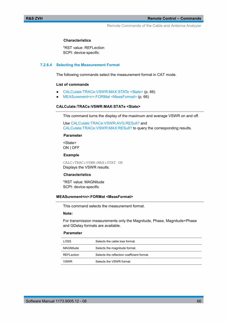
R&S ZVH Remote Control – Commands
Remote Commands of the Cable and Antenna Analyzer
Software Manual 1173.9005.12 - 08 66
Characteristics
*RST value: REFLection SCPI: device-specific
7.2.8.4 Selecting the Measurement Format
The following commands select the measurement format in CAT mode.
List of commands
● CALCulate:TRACe:VSWR:MAX:STATe <State> (p. 66) ● MEASurement<n>:FORMat <MeasFormat> (p. 66)
CALCulate:TRACe:VSWR:MAX:STATe <State>
This command turns the display of the maximum and average VSWR on and off.
Use CALCulate:TRACe:VSWR:AVG:RESult? and CALCulate:TRACe:VSWR:MAX:RESult? to query the corresponding results.
Parameter
<State> ON | OFF
Example
CALC:TRAC:VSWR:MAX:STAT ON Displays the VSWR results.
Characteristics
*RST value: MAGNitude SCPI: device-specific
MEASurement<n>:FORMat <MeasFormat>
This command selects the measurement format.
Note:
For transmission measurements only the Magnitude, Phase, Magnitude+Phase and GDelay formats are available.
Parameter
LOSS Selects the cable loss format.
MAGNitude Selects the magnitude format.
REFLection Selects the reflection coefficient format.
VSWR Selects the VSWR format.

R&S ZVH Remote Control – Commands
Remote Commands of the Cable and Antenna Analyzer
Software Manual 1173.9005.12 - 08 67
Example
MEAS:MODE VECT Switches to vector measurement mode.
MEAS:FUNC:REFL ON Activates reflection measurement.
MEAS:FORM SMIT Displays the reflection in a Smith Chart.
Characteristics
*RST value: MAGNitude SCPI: device-specific
7.2.8.5 Reading Out Measurement Results
The following commands query various measurement results.
List of commands
● CALCulate:TRACe:CABLe:LOSS:RESult? (p. 67) ● CALCulate:TRACe:VSWR:AVG:RESult? (p. 67) ● CALCulate:TRACe:VSWR:MAX:RESult? (p. 68)
CALCulate:TRACe:CABLe:LOSS:RESult?
This command queries the cable loss measurement result.
Return values
Cable loss in dB.
Example
CALC:TRAC:CABL:LOSS:RES? Returns the cable loss.
Characteristics
*RST value: - SCPI: device-specific
CALCulate:TRACe:VSWR:AVG:RESult?
This command queries the average VSWR measurement result.
The command is available when the calculation of the VSWR has been turned on with CALCulate:TRACe:VSWR:MAX:STATe <State>.
Return value
Average VSWR (no unit)

R&S ZVH Remote Control – Commands
Remote Commands of the Cable and Antenna Analyzer
Software Manual 1173.9005.12 - 08 68
Example
CALC:TRAC:VSWR:MAX:STAT ON CALC:TRAC:VSWR:AVG:RES? Queries the average VSWR.
Characteristics
*RST value: - SCPI: device-specific
CALCulate:TRACe:VSWR:MAX:RESult?
This command queries the maximum VSWR measurement result.
The command is available when the calculation of the VSWR has been turned on with CALCulate:TRACe:VSWR:MAX:STATe <State>.
Return value
Maximum VSWR (no unit)
Example
CALC:TRAC:VSWR:MAX:STAT ON CALC:TRAC:VSWR:MAX:RES? Queries the maximum VSWR.
Characteristics
*RST value: - SCPI: device-specific
7.2.8.6 Calibrating the Measurement
The following commands control calibration of cable measurements.
List of commands
● CALibration:ABORt (p. 69) ● CALibration:ATTenuation:STATus? (p. 69) ● CALibration:CONTinue? (p. 69) ● CALibration:MODE? (p. 70) ● CALibration:STARt? <CalibrationMethod> (p. 70) ● SYSTem:PRESet:CALibration:DISCard <State> (p. 71)

R&S ZVH Remote Control – Commands
Remote Commands of the Cable and Antenna Analyzer
Software Manual 1173.9005.12 - 08 69
CALibration:ABORt
This command aborts calibration.
This command is an event and therefore has no query and no *RST value.
Example
CAL:ABOR Aborts calibration.
Characteristics
*RST value: - SCPI: device-specific
CALibration:ATTenuation:STATus?
This command queries the current calibration state.
This command is a query and therefore has no *RST value.
Return values
NORMalized full calibration
APPRoximate approximate calibration (caused by a change of attenuation, for example): measurement uncertainty must be anticipated
Example
CAL:STAT? Queries the calibration status of the R&S ZVH.
Characteristics
*RST value: - SCPI: device-specific
CALibration:CONTinue?
This command resumes calibration after a calibration standard has been connected.
After the command has been sent, it returns instructions on what to do to continue the calibration process and finish it successfully.
This command is a query and therefore has no *RST value.
Example
CAL:CONT? Resumes calibration and would return, e.g.:
'Connect Load to Port 1' Connect the load before resuming calibration.

R&S ZVH Remote Control – Commands
Remote Commands of the Cable and Antenna Analyzer
Software Manual 1173.9005.12 - 08 70
Characteristics *RST value: - SCPI: device-specific
CALibration:MODE?
This command queries the general current calibration state.
This command is a query and therefore has no *RST value.
Return values
0 Not calibrated
1 Calibrated
Example CAL:MODE? would return, e.g. 0
Characteristics *RST value: - SCPI: device-specific
CALibration:STARt? <CalibrationMethod>
This command selects a calibration method and initiates calibration.
After the command has been sent, it returns instructions on what to do to continue the calibration process and finish it successfully.
This command is a query and therefore has no *RST value.
Parameter <CalibrationMethod>
F2PCal Full 2-Port calibration
F2PHighacc Full 2-Port High Accuracy
S11Cal Full 1-Port calibration
S11easy Easy 1-Port calibration (Port 1) (CAT mode only)
S12Cal Normalize transmission with isolation (CAT mode only)
S12Norm Normalize transmission (CAT mode only)
S21Cal Normalize transmission with isolation (CAT mode only)
S21Norm Normalize transmission (CAT mode only)
S22Cal Full 1-Port calibration
S22easy Easy 1-Port calibration (Port 2) (CAT mode only)
T2PCal Normalize transmission with isolation (network analysis only)
T2PNorm Normalize transmission (CAT mode only)

R&S ZVH Remote Control – Commands
Remote Commands of the Cable and Antenna Analyzer
Software Manual 1173.9005.12 - 08 71
Return values
<Instructions>
Connect Open to Port 1 Connect the open to port 1 before resuming calibration.
Connect Open to Port 2 Connect the open to port 2 before resuming calibration.
Connect Short to port 1 Connect the short to port 1 before resuming calibration.
Connect Short to port 2 Connect the short to port 2 before resuming calibration.
Connect Load to port 1 Connect the short to port 1 before resuming calibration.
Connect Load to port 2 Connect the short to port 2 before resuming calibration.
Connect Through Connect a through to ports 1 and 2.
Disconnect DUT from port 1
Disconnect DUT from port 2
Calibration done Calibration has been finished. No further actions required
Example
CAL:STAR? F2PCal Selects and initiates a full 2-port calibration and would return, e.g.:
'Connect Open to Port 1' Connect the open before resuming calibration.
Characteristics
*RST value: - SCPI: device-specific
SYSTem:PRESet:CALibration:DISCard <State>
This command turns the mechanism that discards or keeps user calibration after a preset on and off.
Parameter
<State> ON | OFF
Example
SYST:PRES:CAL:DISC ON Discards user calibration after a preset.
Characteristics
*RST value: OFF SCPI: device-specific

R&S ZVH Remote Control – Commands
Remote Commands of the Cable and Antenna Analyzer
Software Manual 1173.9005.12 - 08 72
7.2.8.7 Working with a DTF List
The following commands configure the DTF peak list. The peak list is available for DTF measurements only.
List of commands
● CALCulate:TRANsform:DTFault:PEAK:COUNt? (p. 72) ● CALCulate:TRANsform:DTFault:PEAK:DATA<y>? (p. 72) ● CALCulate:TRANsform:DTFault:PEAK[:STATe] <State> (p. 73) ● CALCulate:TRANsform:DTFault:PEAK:THReshold <Threshold> (p. 73)
CALCulate:TRANsform:DTFault:PEAK:COUNt?
This command queries the number of entries in the DTF list.
Return value
<DTFListEntries>
Example
CALC:TRAN:DTF:PEAK:COUN? Queries the number of values in the DTF list.
Characteristics
*RST value: - SCPI: device-specific
CALCulate:TRANsform:DTFault:PEAK:DATA<y>?
This command queries the DTF list.
This command is a query and therefore has no *RST value.
Suffix
<y> Selects an entry in the DTF list.
Return value
<distance>,<return loss>
The number of values depends on the number of peaks that exceed the threshold you can set with CALCulate:TRANsform:DTFault:PEAK:THReshold <Threshold>.
Example
CALC:TRAN:DTF:PEAK:RES2? Reads out the second result in the DTF peak list.
Characteristics
*RST value: - SCPI: device-specific

R&S ZVH Remote Control – Commands
Remote Commands of the Cable and Antenna Analyzer
Software Manual 1173.9005.12 - 08 73
CALCulate:TRANsform:DTFault:PEAK[:STATe] <State>
This command turns the display of the DTF list on and off.
Parameter
ON | OFF
Example
CALC:TRAN:DTF:PEAK ON Turns on the DTF peak list.
Characteristics
*RST value: - SCPI: device-specific
CALCulate:TRANsform:DTFault:PEAK:THReshold <Threshold>
This commands defines the threshold for the DTF list.
All values that exceed the threshold are in the DTF list. You can query the list with CALCulate:TRANsform:DTFault:PEAK:DATA<y>?.
Parameter
<Threshold> Numeric value that sets the threshold level.
The unit depends on the measurement format.
Example
CALC:TRAN:DTF:PEAK:THR -20 Sets the threshold to -20 dB
Characteristics
*RST value: - SCPI: device-specific

R&S ZVH Remote Control – Commands
Remote Commands of the Spectrum Analyzer
Software Manual 1173.9005.12 - 08 74
7.3 Remote Commands of the Spectrum Analyzer
This section provides a detailed description of all remote control commands required to configure and perform measurements with the spectrum analyzer. These commands are available in spectrum analyzer mode only.
Availability of remote commands for spectrum measurements Note that the listed remote commands take effect only if you have installed option R&S ZVH-K1 and after you have entered the spectrum analyzer operating mode.
Contents
Configuring the Horizontal Axis on page 75 Configuring the Vertical Axis on page 80 Setting the Bandwidths on page 86 Performing and Triggering Measurements on page 88 Working with Traces on page 94 Using Markers on page 99 Using Display Lines and Limit Lines on page 106 Configuring and Using Measurement Functions on page 112

R&S ZVH Remote Control – Commands
Remote Commands of the Spectrum Analyzer
Software Manual 1173.9005.12 - 08 75
7.3.1 Configuring the Horizontal Axis
The following commands configure the horizontal (frequency) axis of the active display.
List of commands
● [SENSe:]FREQuency:CENTer <Frequency> (p. 36) ● [SENSe:]FREQuency:CENTer:STEP <StepSize> (p. 36) ● [SENSe:]FREQuency:CENTer:STEP:LINK <StepSizeCoupling> (p. 37) ● [SENSe:]FREQuency:INPut:MODE <InputMode> (p. 76) ● [SENSe:]FREQuency:MODE <OperationMode> (p. 77) ● [SENSe:]FREQuency:OFFSet <FrequencyOffset> (p. 77) ● [SENSe:]FREQuency:SPAN <Span> (p. 38) ● [SENSe:]FREQuency:SPAN:AUTO <State> (p. 38) ● [SENSe:]FREQuency:SPAN:FULL (p. 78) ● [SENSe:]FREQuency:STARt <StartFrequency> (p. 39) ● [SENSe:]FREQuency:STOP <StopFrequency> (p. 39)
For a detailed description of all commands not included here, refer to "Configuring the Horizontal Axis" in CAT mode.
[SENSe:]FREQuency:CENTer <Frequency>
This command defines the center frequency of the R&S ZVH.
In spectrum analyzer mode, the command also defines the measuring frequency for time domain measurements (span = 0).
Parameter
<Frequency> Numeric value in Hz.
The range depends on the operating mode and is specified in the data sheet.
Example
FREQ:CENT 100MHz Defines a center frequency of 100 MHz.
Characteristics
*RST value: fmax /2 with fmax = maximum frequency SCPI: conform
[SENSe:]FREQuency:CENTer:STEP <StepSize>
This command defines the center frequency step size.
Parameter
<StepSize> Numeric value in Hz.
The range is from 1 Hz to fmax.

R&S ZVH Remote Control – Commands
Remote Commands of the Spectrum Analyzer
Software Manual 1173.9005.12 - 08 76
Example
FREQ:CENT:STEP 120MHz Defines a CF step size of 120 MHz.
Characteristics
*RST value: – (AUTO 0.1*SPAN is switched on) SCPI: conform
[SENSe:]FREQuency:CENTer:STEP:LINK <StepSizeCoupling>
This command couples and decouples the center frequency step size to the span.
For time domain measurements, the command couples the step size to the resolution bandwidth.
Parameter
<StepSizeCoupling>
DIVTen Couples the step size to the span (10 %).
OFF Turns the coupling off (manual step size).
Example
FREQ:CENT:STEP:LINK DIVT Couples the step size to 10% of the span.
Characteristics
*RST value: DIVTen SCPI: device-specific
[SENSe:]FREQuency:INPut:MODE <InputMode>
This command selects the frequency mode. Select the Channel frequency mode only if you want to work with channel tables. In this case, the input of the center frequency is not a frequency value, but a channel number.
Parameter
<InputMode>
FREQuency Sets the frequency input mode to frequency input (in Hz).
CHANnel Sets the frequency input mode to selection of a channel.
Example
FREQ:INP:MODE CHAN Sets the frequency mode to work with channel tables.
Characteristics
*RST value: FREQ SCPI: device-specific
R&S ZVH Remote Control – Commands
Remote Commands of the Spectrum Analyzer
Software Manual 1173.9005.12 - 08 77
[SENSe:]FREQuency:MODE <OperationMode>
This command the measurement domain (frequency or time).
In the time domain (CW and FIXed), set the frequency with:
- [SENSe:]FREQuency:CENTer <Frequency>
In the frequency domain (SWEep), set it with
- [SENSe:]FREQuency:CENTer <Frequency> - [SENSe:]FREQuency:SPAN <Span> - [SENSe:]FREQuency:STARt <StartFrequency> - [SENSe:]FREQuency:STOP <StopFrequency>
Parameter
<OperationMode>
CW Selects the time domain (span = 0)
FIXed Selects the time domain (span = 0)
SWEep Selects the frequency domain (span > 0).
Example
FREQ:MODE SWE Activates frequency domain measurements.
Characteristics
*RST value: SWEep SCPI: conform
[SENSe:]FREQuency:OFFSet <FrequencyOffset>
This command defines a frequency offset.
Parameter
<FrequencyOffset> Numeric value in the range from -100 GHz to 100 GHz.
Example
FREQ:OFFS 1GHZ Defines a frequency offset of 1 GHz.
Characteristics
*RST value: 0 Hz SCPI: conform

R&S ZVH Remote Control – Commands
Remote Commands of the Spectrum Analyzer
Software Manual 1173.9005.12 - 08 78
[SENSe:]FREQuency:SPAN <Span>
This command defines the frequency span.
If you set a span of 0 Hz in spectrum mode, the R&S ZVH starts a measurement in the time domain.
Parameter
<Span> Numeric value in Hz. The value range is specified in the data sheet.
Example
FREQ:SPAN 10MHz Defines a span of 10 MHz.
Characteristics
*RST value: fmax with fmax = maximum frequency SCPI: conform
[SENSe:]FREQuency:SPAN:AUTO <State>
This command turns the automatic calculation of the ideal span on and off.
Parameter
<State> ON | OFF
Example
FREQ:SPAN:AUTO ON Turns automatic span determination on and off.
Characteristics
*RST value: OFF SCPI: device-specific
[SENSe:]FREQuency:SPAN:FULL
This command restores the full span.
This command is an event and therefore has no query and no *RST value.
Example
FREQ:SPAN:FULL Restores full span.
Characteristics
*RST value: – SCPI: conform
R&S ZVH Remote Control – Commands
Remote Commands of the Spectrum Analyzer
Software Manual 1173.9005.12 - 08 79
[SENSe:]FREQuency:STARt <StartFrequency>
This command defines the start frequency for measurements in the frequency domain (span > 0).
Parameter
<StartFrequency> Numeric value in Hz.
The range depends on the operating mode and is specified in the datasheet.
Example
FREQ:STAR 20MHz Defines a start frequency of 20 MHz.
Characteristics
*RST value: 0 SCPI: conform
[SENSe:]FREQuency:STOP <StopFrequency>
This command defines the stop frequency for measurements in the frequency domain (span > 0).
Parameter
<StopFrequency> Numeric value in Hz.
The range depends on the operating mode and is specified in the datasheet.
Example
FREQ:STOP 2000MHz Defines a stop frequency of 2 GHz
Characteristics
*RST value: fmax SCPI: conform

R&S ZVH Remote Control – Commands
Remote Commands of the Spectrum Analyzer
Software Manual 1173.9005.12 - 08 80
7.3.2 Configuring the Vertical Axis
The following commands configure the vertical (level) axis and level parameters of the active display.
The suffix <t> at TRACe is irrelevant for these commands.
The suffix <c> at TRANsducer selects the primary or secondary transducer. The range is <1…2>.
List of commands
● DISPlay[:WINDow]:TRACe<t>:Y[:SCALe]:ADJust (p. 41) ● DISPlay[:WINDow]:TRACe<t>:Y:SPACing <Scaling> (p. 80) ● DISPlay[:WINDow]:TRACe<t>:Y[:SCALe] <DisplayRange> (p. 81) ● DISPlay[:WINDow]:TRACe<t>:Y[:SCALe]:RLEVel <ReferenceLevel> (p. 81) ● DISPlay[:WINDow]:TRACe<t>:Y[:SCALe]:RLEVel:OFFSet <Offset> (p. 81) ● DISPlay[:WINDow]:TRACe<t>:Y[:SCALe]:RPOSition <ReferencePosition> (p. 82) ● INPut:ATTenuation <Attenuation> (p. 45) ● INPut:ATTenuation:MODE <AttenuationMode> (p. 82) ● INPut:ATTenuation:AUTO <State> (p. 83) ● INPut:GAIN:STATe <State> (p. 83) ● INPut:IMPedance <Impedance> (p. 83) ● [SENSe:]CORRection:TRANsducer<c>[:STATe] <State> (p. 84) ● [SENSe:]CORRection:TRANsducer<c>:SELect <TransducerFactor> (p. 84) ● [SENSe:]CORRection:TRANsducer<c>:UNIT? (p. 84) ● UNIT:POWer <Unit> (p. 85)
For a detailed description of all commands not included here, refer to "Configuring the Vertical Axis" in CAT mode.
DISPlay[:WINDow]:TRACe<t>:Y:SPACing <Scaling>
This command selects the scaling of the vertical axis.
Parameter
<Scaling>
LOGarithmic Selects a logarithmic scale.
LINear Selects a linear scale (%).
Example
DISP:TRAC:Y:SPAC LIN Selects linear scaling of the level axis.
Characteristics
*RST value: LOGarithmic SCPI: conform

R&S ZVH Remote Control – Commands
Remote Commands of the Spectrum Analyzer
Software Manual 1173.9005.12 - 08 81
DISPlay[:WINDow]:TRACe<t>:Y[:SCALe] <DisplayRange>
This command defines the display range of the vertical axis.
Note that you have to set a logarithmic scaling before you can use this command with DISPlay[:WINDow]:TRACe<t>:Y:SPACing. For a linear scale, you can not modify the display range as it is fixed.
Parameter
<DisplayRange> numeric value in the range from 10 dB to 200 dB
Example
DISP:TRAC:Y 110dB Sets the display range to 110 dB.
Characteristics
*RST value: 100dB SCPI: device–specific
DISPlay[:WINDow]:TRACe<t>:Y[:SCALe]:RLEVel <ReferenceLevel>
This command defines the reference level.
With a reference level offset ≠ 0, the value range of the reference level is modified by the offset.
Parameter
<ReferenceLevel> numeric value that sets the reference level; the unit depends on UNIT:POWer.
The available value range is specified in the data sheet.
Example
DISP:TRAC:Y:RLEV –60dBm Sets the reference level to -60 dBm.
Characteristics
*RST value: –20dBm SCPI: conform
DISPlay[:WINDow]:TRACe<t>:Y[:SCALe]:RLEVel:OFFSet <Offset>
This command defines a reference level offset.
Parameter
<Offset> numeric value (dB) that sets the reference level offset
The available value range is from -200dB to 200dB.

R&S ZVH Remote Control – Commands
Remote Commands of the Spectrum Analyzer
Software Manual 1173.9005.12 - 08 82
Example
DISP:TRAC:Y:RLEV:OFFS –10dB Characteristics
*RST value: 0dB SCPI: conform
DISPlay[:WINDow]:TRACe<t>:Y[:SCALe]:RPOSition <ReferencePosition>
This command defines the position of the reference level on the display grid.
First, you have to set a logarithmic scale for the vertical axis with DISPlay[:WINDow]:TRACe<t>:Y:SPACing. For a linear scale, you can not modify the reference position.
Parameter
<ReferencePosition> numeric value (%) that defines the reference position
The available value range is from 1 to 10.
Example
DISP:TRAC:Y:RPOS 5 Sets the reference position to the 5th grid line.
Characteristics
*RST value:10 SCPI: conform
INPut:ATTenuation:MODE <AttenuationMode>
This command selects the attenuation mode.
Parameter
<AttenuationMode>
LDIStortion Selects "Auto Low Distortion" mode.
LNOise Selects "Auto Low Noise" mode.
Example
INP:ATT:MODE LNO Sets the attenuation mode to Auto Low Noise.
Characteristics
*RST value: LNOise SCPI: device-specific

R&S ZVH Remote Control – Commands
Remote Commands of the Spectrum Analyzer
Software Manual 1173.9005.12 - 08 83
INPut:ATTenuation:AUTO <State>
This command couples and decouples input attenuation to the reference level.
Parameter
<State> ON | OFF
Example
INP:ATT:AUTO ON Couples the attenuation set on the attenuator to the reference level.
Characteristics
*RST value: ON SCPI: conform
INPut:GAIN:STATe <State>
This command turns the preamplifier on and off.
Parameter
<State> ON | OFF
Example
INP:GAIN:STAT ON Activates the preamplifier
Characteristics
*RST value: OFF SCPI: conform
INPut:IMPedance <Impedance>
This command selects the nominal input impedance. The set impedance is taken into account in all level indications of results.
The setting 75 Ω should be selected, if the 50 Ω input impe da nce is
transformed to a higher impedance using a 75 Ω adapter of the RAZ type (= 25 Ω in series to the input impedance of the instrument). The correction value in this case is 1.76 dB = 10 log (75Ω / 50Ω).
Parameter
<Impedance> 50 | 75
Example
INP:IMP 75 Sets the input impedance to 75 Ohm.

R&S ZVH Remote Control – Commands
Remote Commands of the Spectrum Analyzer
Software Manual 1173.9005.12 - 08 84
Characteristics
*RST value: 50 Ω
SCPI: conform
[SENSe:]CORRection:TRANsducer<c>[:STATe] <State>
This command turns a transducer factor on and off.
Before turning it on, you have to select a transducer factor with [SENSe:]CORRection:TRANsducer<c>:SELect.
Parameter
<State> ON | OFF
Example
CORR:TRAN1 ON Activates the primary transducer
Characteristics
*RST value: OFF SCPI: device-specific
[SENSe:]CORRection:TRANsducer<c>:SELect <TransducerFactor>
This command selects a transducer factor.
If <name> does not exist yet, a new transducer factor is created.
The suffix<1...2> specifies the primary or secondary transducer.
Parameter
<Transducerfactor> string containing the file name of the transducer factor.
If the file does not exist, the R&S ZVH creates a new transducer factor.
Example
CORR:TRAN2:SEL 'FSH-Z38.sectrd' Selects the FSH-Z38 secondary transducer factor.
Characteristics
*RST value: - SCPI: device-specific
[SENSe:]CORRection:TRANsducer<c>:UNIT?
This command queries the unit of the current transducer factor.
Example
CORR:TRAN2:UNIT? Queries the unit of the primary transducer.

R&S ZVH Remote Control – Commands
Remote Commands of the Spectrum Analyzer
Software Manual 1173.9005.12 - 08 85
Characteristics
*RST value: - SCPI: device-specific
UNIT:POWer <Unit>
This command selects the unit of the vertical axis.
The availability of units depends on the operating mode and type of measurement.
Parameter
<Unit> DBM | DBUV | DBMV | V | W | DUVM | DUAM | V_M | W_M2
Note that the availability of units depends on the operating mode.
Example
UNIT:POW DBUV Sets the power unit to dBμV.
Characteristics
*RST value: DBM SCPI: conform

R&S ZVH Remote Control – Commands
Remote Commands of the Spectrum Analyzer
Software Manual 1173.9005.12 - 08 86
7.3.3 Setting the Bandwidths
The following commands configure the filter bandwidths of the R&S ZVH. Note that both groups of commands (BANDwidth and BWIDth) are the same.
List of commands
● [SENSe:]BANDwidth|BWIDth[:RESolution] <ResBW> (p. 86) ● [SENSe:]BANDwidth|BWIDth[:RESolution]:AUTO <State> (p. 86) ● [SENSe:]BANDwidth|BWIDth:VIDeo <VideoBW> (p. 87) ● [SENSe:]BANDwidth|BWIDth:VIDeo:AUTO <State> (p. 87)
[SENSe:]BANDwidth|BWIDth[:RESolution] <ResBW>
This command defines the resolution bandwidth.
Parameter
<ResBW> Numeric value in Hz.
The available value range is from 1 Hz to 3 MHz in 1 - 3 - 5 steps. In addition, you can select a 200 kHz bandwidth.
Example
BAND 100 kHz Sets the resolution bandwidth to 100 kHz
Characteristics
*RST value: - (AUTO is set to ON) SCPI: conform
[SENSe:]BANDwidth|BWIDth[:RESolution]:AUTO <State>
This command couples and decouples the resolution bandwidth to the span.
Parameter
<State> ON | OFF
Example
BAND:AUTO OFF Decouples the resolution bandwidth from the span.
Characteristics
*RST value: ON SCPI: conform

R&S ZVH Remote Control – Commands
Remote Commands of the Spectrum Analyzer
Software Manual 1173.9005.12 - 08 87
[SENSe:]BANDwidth|BWIDth:VIDeo <VideoBW>
This command defines the video bandwidth.
Parameter
<VideoBW> Numeric value in Hz.
The available value range is from 1 Hz to 3 MHz in 1 - 3 steps.
Example
BAND:VID 10kHz Sets the video bandwidth to 10 kHz.
Characteristics
*RST value: - (AUTO is set to ON) SCPI: conform
[SENSe:]BANDwidth|BWIDth:VIDeo:AUTO <State>
This command couples and decouples the video bandwidth to the resolution bandwidth.
Parameter
<State> ON | OFF
Example
BAND:VID:AUTO OFF Turns off video bandwidth coupling.
Characteristics
*RST value: ON SCPI: conform

R&S ZVH Remote Control – Commands
Remote Commands of the Spectrum Analyzer
Software Manual 1173.9005.12 - 08 88
7.3.4 Performing and Triggering Measurements
The following commands control the actual measurement process, including trigger functionality.
7.3.4.1 Performing the Measurement
The following commands initialize a measurement and set up the sweep.
List of commands
● *WAI (p. 34) ● ABORt (p. 88) ● INITiate[:IMMediate] (p. 88) ● INITiate:CONTinuous <SweepMode> (p. 89) ● [SENSe:]SWEep:COUNt <SweepCount> (p. 89) ● [SENSe:]SWEep:POINts? (p. 90) ● [SENSe:]SWEep:TIME <SweepTime> (p. 90) ● [SENSe:]SWEep:TIME:AUTO <State> (p. 90)
ABORt
This command aborts the current measurement and resets the trigger system.
This command is an event and therefore has no query and no *RST value.
Example
ABOR; INIT:IMM Aborts a measurement and starts a new one.
Characteristics
RST value: – SCPI: conform
INITiate[:IMMediate]
The command initiates a new measurement sequence.
With sweep count > 0 or average count > 0, this means a restart of the indicated number of measurements. With trace functions MAXHold, MINHold and AVERage, the previous results are reset on restarting the measurement.
In single sweep mode, synchronization to the end of the indicated number of measurements can be achieved with the command *OPC, *OPC? or *WAI. In continuous–sweep mode, synchronization to the sweep end is not possible since the overall measurement never ends.
This command is an event and therefore has no query and no *RST value.

R&S ZVH Remote Control – Commands
Remote Commands of the Spectrum Analyzer
Software Manual 1173.9005.12 - 08 89
Example
INIT:CONT OFF DISP:WIND:TRAC:MODE AVER Turns single sweep mode and trace averaging on.
INIT;*WAI Starts the measurement and waits for the end of the sweep.
Characteristics
*RST value: – SCPI: conform
INITiate:CONTinuous <SweepMode>
This command selects the sweep mode.
Parameter
<SweepMode>
ON Selects continuous sweeps.
OFF Selects single sweep.
Example
INIT:CONT OFF Turns on single sweep mode.
Characteristics
*RST value: ON SCPI: conform
[SENSe:]SWEep:COUNt <SweepCount>
This command defines the number of sweeps included in a single sweep. It also defines the number of sweeps the R&S ZVH uses to average traces or calculate maximum values.
The R&S ZVH performs one sweep for sweep count 0 or 1.
Parameter
<SweepCount> 0 to 999
Example
SWE:COUN 64 Defines a sweep count of 64 sweeps.
INIT:CONT OFF INIT;*WAI Turns on single sweep mode, starts the sweep and waits for its end.

R&S ZVH Remote Control – Commands
Remote Commands of the Spectrum Analyzer
Software Manual 1173.9005.12 - 08 90
Characteristics
*RST value: 1 SCPI: conform
[SENSe:]SWEep:POINts?
This command queries the number of measurement points in a single sweep.
This command is a query and therefore has no *RST value.
Return value
Number of sweep points.
Example
SWE:POIN? Returns the number of sweep points.
Characteristics
*RST value: – SCPI: conform
[SENSe:]SWEep:TIME <SweepTime>
This command defines the sweep time.
If you set a sweep time in spectrum mode with this command, the R&S ZVH decouples the sweep time from the span and the resolution and video bandwidths.
Parameter
<SweepTime> Numeric value in seconds.
The available value range is specified in the datasheet.
Example
SWE:TIME 10s Sets the sweep time to 10 s
Characteristics
*RST value: - (AUTO is set to ON) SCPI: conform
[SENSe:]SWEep:TIME:AUTO <State>
This command couples and decouples the sweep time to the span and the resolution and video bandwidths.
Parameter
<State> ON | OFF

R&S ZVH Remote Control – Commands
Remote Commands of the Spectrum Analyzer
Software Manual 1173.9005.12 - 08 91
Example
SWE:TIME:AUTO ON Switches on the coupling to frequency span and bandwidths.
Characteristics
*RST value: ON SCPI: conform
7.3.4.2 Triggering Measurements
The following commands set up trigger conditions if you are using a trigger for the measurement.
List of commands
● [SENSe:]SWEep:EGATe <State> (p. 91) ● [SENSe:]SWEep:EGATe:HOLDoff <GateDelay> (p. 91) ● [SENSe:]SWEep:EGATe:LENGth <GateLength> (p. 92) ● [SENSe:]SWEep:EGATe:TIME <SweepTime> (p. 92) ● TRIGger[:SEQuence]:HOLDoff[:TIME] <TriggerDelay> (p. 48) ● TRIGger[:SEQuence]:LEVel:VIDeo <TriggerLevel> (p. 92) ● TRIGger[:SEQuence]:SLOPe <TriggerSlope> (p. 49) ● TRIGger[:SEQuence]:SOURce <TriggerSource> (p. 93)
For a detailed description of all commands not included here, refer to "Triggering Measurements" in CAT mode.
[SENSe:]SWEep:EGATe <State>
This command turns a gated trigger on and off.
Parameter
<State> ON | OFF
Example
SWE:EGAT ON Activates the gated trigger.
Characteristics
*RST value: off SCPI: device-specific
[SENSe:]SWEep:EGATe:HOLDoff <GateDelay>
This command defines the length of the gate delay.
Parameter
<GateDelay> Numeric value in the range from 0 s to 100 s.

R&S ZVH Remote Control – Commands
Remote Commands of the Spectrum Analyzer
Software Manual 1173.9005.12 - 08 92
Example
SWE:EGAT:HOLD 2.5 Sets a gate delay of 2.5 seconds.
Characteristics
*RST value: 0 s SCPI: device-specific
[SENSe:]SWEep:EGATe:LENGth <GateLength>
This command defines the gate length.
Parameter
<GateLength> Numeric value in the range from 10 µs to 100 s.
Example
SWE:EGAT:LENG 2.5 Sets a gate length of 2.5 seconds.
Characteristics
*RST value: 400 µs SCPI: device-specific
[SENSe:]SWEep:EGATe:TIME <SweepTime>
This command defines the sweep time for the gated trigger.
Parameter
<SweepTime> Numeric value in seconds.
Example
SWE:GATE:TIME 4ms Sets a sweep time of 4 ms for the gated trigger.
Characteristics
*RST value: 400 µs SCPI: device-specific
TRIGger[:SEQuence]:LEVel:VIDeo <TriggerLevel>
This command defines the level of the video trigger.
Video trigger is available for time domain measurements (span = 0).
Parameter
<TriggerLevel> Numeric value in the range from 0 % to 100 %.
R&S ZVH Remote Control – Commands
Remote Commands of the Spectrum Analyzer
Software Manual 1173.9005.12 - 08 93
Example
TRIG:LEV:VID 50PCT Sets the trigger level to 50%.
Characteristics
*RST value: 50 PCT SCPI: device–specific
TRIGger[:SEQuence]:SOURce <TriggerSource>
This command selects the trigger source.
Parameter
<TriggerSource>
IMMediate Selects Free Run measurements.
EXTernal Selects an external trigger.
VIDeo Selects the video trigger.
For more information see R&S ZVH operating manual chapter "Setting the Sweep"
Example
TRIG:SOUR EXT Selects the external trigger input as source of the trigger signal
Characteristics
*RST value: IMMediate SCPI: conform

R&S ZVH Remote Control – Commands
Remote Commands of the Spectrum Analyzer
Software Manual 1173.9005.12 - 08 94
7.3.5 Working with Traces
The following commands set up the trace and the various functions associated with it, e.g. trace mathematics or the selection of the detector.
The suffix <t> is in the range {1..2} and selects the number of the trace.
List of commands
● CALCulate:MATH<t>[:EXPRession][:DEFine] <Expression> (p. 94) ● CALCulate:MATH<t>:COPY:MEMory (p. 50) ● CALCulate:MATH<t>:STATe <State> (p. 95) ● DISPlay[:WINDow]:TRACe<t>[:STATe] <State> (p. 95) ● DISPlay[:WINDow]:TRACe<t>:MEMory[:STATe] <State> (p. 50) ● DISPlay[:WINDow]:TRACe<t>:MODE <TraceMode> (p. 95) ● FORMat:BORDer <ByteOrder> (p. 96) ● [SENSe:]DETector<t>[:FUNCtion] <Detector> (p. 96) ● [SENSe:]DETector<t>[:FUNCtion]:AUTO <State> (p. 97) ● TRACe<t>[:DATA]? <Destination> (p. 97) ● FORMat[:DATA] <DataFormat> (p. 98)
For a detailed description of all commands not included here, refer to "Working with Traces" in CAT mode.
CALCulate:MATH[:EXPRession][:DEFine] <Expression>
This command defines the mathematical expression for relating traces to trace 1.
You have to activate trace mathematics with CALCulate:MATH<t>:STATe <State> first.
Parameter
<Expression>
(IMPLied - memory) Subtracts the trace in memory from the current trace.
(memory - IMPlied) Subtracts the current trace from the trace in memory.
Example
CALC:MATH (MTRACE–TRACE) Selects the subtraction of the current trace from trace in the memory.
Characteristics
*RST value: – SCPI: conform

R&S ZVH Remote Control – Commands
Remote Commands of the Spectrum Analyzer
Software Manual 1173.9005.12 - 08 95
CALCulate:MATH:STATe <State>
This command turns trace mathematics on and off.
Parameter
<State> ON | OFF
Example
CALC:MATH:STAT ON Switches on the trace mathematics.
Characteristics
*RST value: OFF SCPI: conform
DISPlay[:WINDow]:TRACe<t>[:STATe] <State>
This command turns a trace on and off.
Parameter
<State> ON | OFF
Example
DISP:TRAC2 ON Turns the trace on.
Characteristics
*RST value: ON for TRACe1, OFF for TRACe2 SCPI: conform
DISPlay[:WINDow]:TRACe<t>:MODE <TraceMode>
This command selects the trace mode.
If you are using the average, max hold or min hold trace mode, you can set the number of measurements with [SENSe:]SWEep:COUNt <SweepCount>. Note that synchronization to the end of the average count is possible only in single sweep mode.
Parameter
<TraceMode> AVERage | MAXHold | MINHold | VIEW | WRITe
You can turn off the trace with DISPlay[:WINDow]:TRACe<t>[:STATe] <State>.
For more information see the operating manual, chapter "Trace Mode".

R&S ZVH Remote Control – Commands
Remote Commands of the Spectrum Analyzer
Software Manual 1173.9005.12 - 08 96
Example
SWE:CONT OFF SWE:COUN 16 Turn on single sweep mode and sets the number of measurements to 16.
DISP:TRAC:MODE MAXH Activates MAXHold mode for the trace.
INIT;*WAI Starts the measurement and waits for the end of the 16 sweeps.
Characteristics
*RST value: WRITe SCPI: device–specific
FORMat:BORDer <ByteOrder>
This command selects the format of binary data.
Parameters
<ByteOrder>
SWAPped The least significant byte is transferred first (little endian).
NORMal The most significant byte is transferred first big endian).
Example
FORM:BORD NORM Changes the byte order to normal mode
Characteristics
*RST value SWAPped SCPI: conform
[SENSe:]DETector<t>[:FUNCtion] <Detector>
This command selects the detector.
Parameter
<Detector> APEak | NEGative | POSitive | SAMPle | RMS
For more information see the operating manual, chapter "Detectors".
Example
DET POS Sets the detector to "positive peak".
Characteristics
*RST value: POS SCPI: conform

R&S ZVH Remote Control – Commands
Remote Commands of the Spectrum Analyzer
Software Manual 1173.9005.12 - 08 97
[SENSe:]DETector<t>[:FUNCtion]:AUTO <State>
This command couples and decouples the detector to the trace mode.
Parameter
<State> ON | OFF
Example
DET:AUTO OFF Turns off automatic detector selection.
Characteristics
*RST value: ON SCPI: conform
TRACe[:DATA]? <Destination>
This command queries the trace data of the current measurement.
It also transfers data from a file to a particular trace.
With FORMat[:DATA] <DataFormat> command, you can set the data format.
Parameter
<Destination>
TRACE1 Queries the data of trace 1.
TRACE2 Queries the data of trace 2.
LIST Queries the peak list of the measurement.
Return value
The R&S ZVH returns 631 values. Each value corresponds to one pixel of a trace.
The unit depends on the measurement and the unit you have set with UNIT:POWer <Unit>.
Note: If you use the auto peak detector, the command reads out positive peak values only.
Example
TRAC:DATA? TRACE1 Reads out the data for trace 1
Characteristics
*RST value: - SCPI: conform

R&S ZVH Remote Control – Commands
Remote Commands of the Spectrum Analyzer
Software Manual 1173.9005.12 - 08 98
FORMat[:DATA] <DataFormat>
This command selects the data format that is used for transmission of trace data from the R&S ZVH to the controlling computer.
Note that the command has no effect for data that you send to the R&S ZVH. The R&S ZVH automatically recognizes the data it receives, regardless of the format.
Parameter
<DataFormat>
ASCii Returns the data in ASCII format, separated by commas.
REAL,32 Returns the data as 32-bit IEEE 754 floating point numbers in the "definite length block format".
In REAL,32 format, a string of return values would look like: #42524<value 1><value 2>...<value n> with
#4 Number of digits of the following number of data bytes (= 4 in this example)
2524 Number of following data bytes (2524, corresponds to the 631 sweep points of the R&S ZVH.
<value> 4-byte floating point value
Example
FORM ASC Selects the ASCii data format.
Characteristics
*RST value: ASCii SCPI: conform

R&S ZVH Remote Control – Commands
Remote Commands of the Spectrum Analyzer
Software Manual 1173.9005.12 - 08 99
7.3.6 Using Markers
● Markers and Delta Markers on page 99 ● Marker Functions on page 99
7.3.6.1 Markers and Delta Markers
The following commands are for setting and controlling markers and deltamarkers.
In spectrum mode mode, the suffix <n> at CALCulate selects the trace.
The suffix <m> at MARKer is in the range {1..6} and selects the marker or deltamarker.
List of commands
● CALCulate<n>:DELTamarker<m>[:STATe] <State> (p. 54) ● CALCulate<n>:DELTamarker<m>:AOFF (p. 55) ● CALCulate<n>:DELTamarker<m>:MAXimum[:PEAK] (p. 55) ● CALCulate<n>:DELTamarker<m>:MAXimum:NEXT (p. 55) ● CALCulate<n>:DELTamarker<m>:MINimum[:PEAK] (p. 55) ● CALCulate<n>:DELTamarker<m>:X <Coordinate> (p. 56) ● CALCulate<n>:DELTamarker<m>:X:RELative <Distance> (p. 56) ● CALCulate<n>:DELTamarker<m>:Y? (p. 57) ● CALCulate<n>:MARKer<m>[:STATe] <State> (p. 58) ● CALCulate<n>:MARKer<m>:AOFF (p. 58) ● CALCulate<n>:MARKer<m>:MAXimum[:PEAK] (p. 58) ● CALCulate<n>:MARKer<m>:MAXimum:NEXT (p. 59) ● CALCulate<n>:MARKer<m>:MINimum[:PEAK] (p. 59) ● CALCulate<n>:MARKer<m>:X <Coordinate> (p. 59) ● CALCulate<n>:MARKer<m>:X:SLIMits[:STATe] <State> (p. 60) ● CALCulate<n>:MARKer<m>:X:SLIMits:LEFT <SearchLimit> (p. 60) ● CALCulate<n>:MARKer<m>:X:SLIMits:RIGHt <Searchlimit> (p. 61) ● CALCulate<n>:MARKer<m>:Y? (p. 61)
For a detailed description of all commands not included here, refer to "Using Markers" in CAT mode.
7.3.6.2 Marker Functions
The following commands perform various kinds of analysis at the marker position.
The suffix <m> at MARKer is irrelevant, except where noted.
List of commands
● CALCulate:MARKer<m>:COUNt:FREQuency? (p. 100) ● CALCulate:MARKer<m>:COUNt[:STATe] <State> (p. 100) ● CALCulate:MARKer<m>:FREQuency:MODE <InputMode> (p. 101) ● CALCulate:MARKer<m>:FUNCtion:CENTer (p. 101) ● CALCulate:MARKer<m>:FUNCtion:DEModulation[:STATe] <State> (p. 101) ● CALCulate:MARKer<m>:FUNCtion:DEModulation:HOLDoff <Time> (p. 102) ● CALCulate:MARKer<m>:FUNCtion:DEModulation:SELect <Demodulation> (p.102)

R&S ZVH Remote Control – Commands
Remote Commands of the Spectrum Analyzer
Software Manual 1173.9005.12 - 08 100
● CALCulate:MARKer<m>:FUNCtion:NDBDown <Distance> (p. 103) ● CALCulate:MARKer<m>:FUNCtion:NDBDown:FREQuency? (p. 103) ● CALCulate:MARKer<m>:FUNCtion:NDBDown:RESult? (p. 103) ● CALCulate:MARKer<m>:FUNCtion:NDBDown:STATe <State> (p. 104) ● CALCulate:MARKer<m>:FUNCtion:NOISe[:STATe] <State> (p. 104) ● CALCulate:MARKer<m>:FUNCtion:NOISe:RESult? (p. 104) ● CALCulate:MARKer<m>:FUNCtion:REFerence (p. 105)
CALCulate:MARKer<m>:COUNt:FREQuency?
This command performs a frequency measurement at the marker position and returns the result.
To get a valid result, you have to perform a complete sweep with synchronization to the sweep end to make sure that the R&S ZVH actually reaches the frequency you want to measure. This is only possible in single sweep mode.
Before you can use the command, you have to turn on the frequency counter with CALCulate:MARKer<m>:COUNt[:STATe] <State>.
Example
See CALCulate:MARKer<m>:COUNt[:STATe] <State>.
Characteristics
*RST value: – SCPI: device–specific
CALCulate:MARKer<m>:COUNt[:STATe] <State>
This command turns the frequency counter at the marker position on and off.
You can read out the result with CALCulate:MARKer<m>:COUNt:FREQuency?.
Frequency counting is possible only for one marker at a time. If it is activated for another marker, it is automatically deactivated for the previous marker.
To get a valid result, you have to perform a complete sweep with synchronization to the sweep end to make sure that the R&S ZVH actually reaches the frequency you want to measure. This is only possible in single sweep mode.
The suffix <m> selects the marker.
Parameter
<State> ON | OFF
Example
INIT:CONT OFF CALC:MARK ON Turns on single sweep mode and marker 1.
CALC:MARK:COUN ON Turns on the frequency counter for marker 1.

R&S ZVH Remote Control – Commands
Remote Commands of the Spectrum Analyzer
Software Manual 1173.9005.12 - 08 101
INIT;*WAI CALC:MARK:COUN:FREQ? Performs a measurement and queries the results of the frequency counter.
Characteristics
*RST value: OFF SCPI: device–specific
CALCulate:MARKer<m>:FREQuency:MODE <InputMode>
This command selects the marker frequency display mode.
Parameter
<InputMode>
FREQuency Sets the marker frequency mode to frequency input (in Hz).
CHANnel Sets the marker frequency mode to channel input (as a channel number).
Example
CALC:MARK:FREQ:MODE FREQ Selects the frequency display mode.
Characteristics
*RST value: FREQ SCPI: device-specific
CALCulate:MARKer<m>:FUNCtion:CENTer
This command matches the center frequency to the frequency of a marker
If you use a delta marker, the R&S ZVH turns it into a normal marker.
The suffix <m> selects the marker.
This command is an event and therefore has no *RST value and no query.
Example
CALC:MARK1:FUNC:CENT Matches the center frequency to the frequency of marker 1.
Characteristics
*RST value: - SCPI: device-specific
CALCulate:MARKer<m>:FUNCtion:DEModulation[:STATe] <State>
This command turns the audio demodulator on and off when the measurement hits a marker position.
With a span greater than 0, you can define a hold time at the marker position with CALCulate:MARKer<m>:FUNCtion:DEModulation:HOLDoff <Time>.

R&S ZVH Remote Control – Commands
Remote Commands of the Spectrum Analyzer
Software Manual 1173.9005.12 - 08 102
In zero span the demodulation is on permanently.
Parameter
<State> ON | OFF
Example
CALC:MARK3:FUNC:DEM ON Switches on the demodulation for marker 3.
Characteristics
*RST value: OFF SCPI: device–specific
CALCulate:MARKer<m>:FUNCtion:DEModulation:HOLDoff <Time>
This command defines the hold time at the marker position for the demodulation with span > 0.
Parameter
<Time> Numeric value in the range from 10 ms to 500 s.
Example:
CALC:MARK:FUNC:DEM:HOLD 3s Sets a hold time of 3 seconds.
Characteristics:
*RST value: – (DEModulation is set to OFF) SCPI: device–specific
CALCulate:MARKer<m>:FUNCtion:DEModulation:SELect <Demodulation>
This command selects the type of demodulation type for the audio demodulator.
Parameter
<Demodulation> AM | FM
Example
CALC:MARK:FUNC:DEM:SEL FM Selects FM demodulation.
Characteristics
*RST value: AM SCPI: device–specific
R&S ZVH Remote Control – Commands
Remote Commands of the Spectrum Analyzer
Software Manual 1173.9005.12 - 08 103
CALCulate:MARKer<m>:FUNCtion:NDBDown <Distance>
This command defines the distance of the n dB down markers to the reference marker.
Parameter
<Distance> Distance of the temporary markers to the reference marker in dB.
Example
See CALCulate:MARKer<m>:FUNCtion:NDBDown:STATe <State>
Characteristics
*RST value: 3 dB SCPI: device-specific
CALCulate:MARKer<m>:FUNCtion:NDBDown:FREQuency?
This command queries the horizontal position of the n dB down markers.
Return value
<frequency1> Absolute frequency of the n dB marker to the left of the reference marker in Hz.
<frequency2> Absolute frequency of the n dB marker to the right of the reference marker in Hz.
Example
See CALCulate:MARKer<m>:FUNCtion:NDBDown:STATe <State>
Characteristics
*RST value: - SCPI: device-specific
CALCulate:MARKer<m>:FUNCtion:NDBDown:RESult?
This command queries the frequency spacing or bandwidth of the n dB down markers.
Return value
<Bandwidth> Bandwidth in Hz.
Example
See CALCulate:MARKer<m>:FUNCtion:NDBDown:STATe <State>
Characteristics
*RST value: - SCPI: device-specific

R&S ZVH Remote Control – Commands
Remote Commands of the Spectrum Analyzer
Software Manual 1173.9005.12 - 08 104
CALCulate:MARKer<m>:FUNCtion:NDBDown:STATe <State>
This command turns the n dB Down marker function on and off.
Parameter
<State> ON | OFF
Example
CALC:MARK:FUNC:NDBD:STAT ON Turns on the n dB marker function.
CALC:MARK:FUNC:NDBD 3 Positions two temporary markers 3 dB below a reference marker.
CALC:MARK:FUNC:NDBD:FREQ? Queries the frequency position of the n dB Down markers; would return e.g. 100000000,200000000
CALC:MARK:FUNC:NDBD:RES? Queries the measurement result; would return e.g. 100000000
Characteristics
*RST value: OFF SCPI: device-specific
CALCulate:MARKer<m>:FUNCtion:NOISe[:STATe] <State>
This command turns the noise measurement for all markers on and off.
You can query the results of the noise power density at the marker position with CALCulate:MARKer<m>:FUNCtion:NOISe:RESult?.
Parameter
<State> ON | OFF
Example
See CALCulate:MARKer<m>:FUNCtion:NOISe:RESult?.
Characteristics
*RST value: OFF SCPI: device–specific
CALCulate:MARKer<m>:FUNCtion:NOISe:RESult?
This command queries the result of the noise measurement.
To get a valid result, you have to perform a complete sweep with synchronization to the sweep end before reading out the result. This is only possible in single sweep mode.

R&S ZVH Remote Control – Commands
Remote Commands of the Spectrum Analyzer
Software Manual 1173.9005.12 - 08 105
This command is an event and therefore has no *RST value and no query.
Return value
<NoiseLevel>
The unit depends on UNIT:POWer.
Example
INIT:CONT OFF Turns on single sweep mode.
CALC:MARK2 ON CALC:MARK2:FUNC:NOIS ON Turns on marker 2 and assigns the noise measurement to that marker.
INIT;*WAI CALC:MARK2:NOIS:RES? Performs the measurement and queries the noise marker results.
Characteristics
*RST value: – SCPI: device–specific
CALCulate:MARKer<m>:FUNCtion:REFerence
This command matches the reference level to the power level of a marker
If you use a delta marker, the R&S ZVH turns it into a normal marker.
This command is an event and therefore has no *RST value and no query.
Example
CALC:MARK1:FUNC:REF Matches the reference level to the power level of marker 1.
Characteristics
*RST value: - SCPI: device-specific

R&S ZVH Remote Control – Commands
Remote Commands of the Spectrum Analyzer
Software Manual 1173.9005.12 - 08 106
7.3.7 Using Display Lines and Limit Lines
7.3.7.1 Display Lines
The following commands define the position of the display line.
The suffix <n> at CALCulate is irrelevant.
List of commands
● CALCulate<n>:DLINe <Amplitude> (p. 106) ● CALCulate<n>:DLINe:STATe <State> (p. 106)
CALCulate<n>:DLINe <Amplitude>
This command defines the position of a display line.
Parameter
<Amplitude> Numeric value with a variable range and unit.
You can use any unit you want, the R&S ZVH then converts the unit to the currently selected unit. If you omit a unit, the R&S ZVH uses the currently selected unit.
Example
CALC:DLIN –20dBm Sets the display line threshold to -20 dBm.
Characteristics
*RST value: – (STATe to OFF) SCPI: device–specific
CALCulate<n>:DLINe:STATe <State>
This command turns display lines on and off.
Parameter
<State> ON | OFF
Example
CALC:DLIN:STAT OFF Turns on the display line.
Characteristics
*RST value: OFF SCPI: device–specific

R&S ZVH Remote Control – Commands
Remote Commands of the Spectrum Analyzer
Software Manual 1173.9005.12 - 08 107
7.3.7.2 Limit Lines
The following commands define limit lines and perform the corresponding limit checks.
The suffix <n> at CALCulate is irrelevant.
The suffix <k> at LIMit selects the limit line and is in the range <1…2>.
List of commands
● CALCulate<n>:LIMit<k>:BEEP[:STATe] <State> (p. 107) ● CALCulate<n>:LIMit<k>:COMMent? (p. 107) ● CALCulate<n>:LIMit<k>:DEFine (p. 108) ● CALCulate<n>:LIMit<k>:DELete (p. 108) ● CALCulate<n>:LIMit<k>:FAIL? (p. 109) ● CALCulate<n>:LIMit<k>:LOWer:SELect <LimitLine> (p. 109) ● CALCulate<n>:LIMit<k>:LOWer:THReshold <Level> (p. 110) ● CALCulate<n>:LIMit<k>:STATe <State> (p. 110) ● CALCulate<n>:LIMit<k>:UNIT:X? (p. 110) ● CALCulate<n>:LIMit<k>:UNIT[:Y]? (p. 111) ● CALCulate<n>:LIMit<k>:UPPer:SELect <LimitLine> (p. 111) ● CALCulate<n>:LIMit<k>:UPPer:THReshold <Level> (p. 111)
CALCulate<n>:LIMit<k>:BEEP[:STATe] <State>
This command turns the beeper that beeps if a limit line is violated on and off.
Parameter
<State> ON | OFF
Example
CALC:LIM:BEEP ON Activates the audio beep.
Characteristics
*RST value: OFF SCPI: device-specific
CALCulate<n>:LIMit<k>:COMMent?
This command queries the description of a limit line.
This command is a query and therefore has no RST value.
Return value
<Comment> String containing the description of the limit line.
Example
CALC:LIM:COMM? Queries the description of limit line 1.

R&S ZVH Remote Control – Commands
Remote Commands of the Spectrum Analyzer
Software Manual 1173.9005.12 - 08 108
Characteristics
*RST value: - SCPI: device-specific
CALCulate<n>:LIMit<k>:DEFine
<Name>,<Comment>,<Unit>,<Scale>,<Unit>,<x1>,<y1>[,<xn>,<yn>]
This command defines the shape of a limit line.
After you have defined the shape of the limit line you still have to activate it with CALCulate<n>:LIMit<k>:UPPer:SELect <LimitLine> before it takes effect.
Parameters
<Name> String containing the name of the limit line.
Note: if a limit line with the same name already exists, it will be overwritten.
<Comment> String containing a comment for the limit line.
<X-unit> Unit of the x-axis. HZ | S | M
<Scale> Scale of the x-axis: ABS | REL
<Y-unit> Unit of the y-axis: DB | DBM | DBUV | DBMV | DBUVM | DBUAM | VSWR | V | W
<x1>,<xn> Data points on the x-axis.
Note: a limit line may consist of up to 100 horizontal data points.
<y1>,<yn> Data points on the y-axis.
Example
CALC:LIM:DEF 'Line','Example',HZ,ABS,DBM,10000000,-10, 10000000,0,20000000,0 Defines a limit line with three data points.
Characteristics
*RST value: - SCPI: device-specific
CALCulate<n>:LIMit<k>:DELete
This command deletes a limit line.
This command is an event and therefore has no *RST value and no query.

R&S ZVH Remote Control – Commands
Remote Commands of the Spectrum Analyzer
Software Manual 1173.9005.12 - 08 109
Example
CALC:LIM2:DEL Deletes the second limit line
Characteristics
*RST value: - SCPI: device-specific
CALCulate<n>:LIMit<k>:FAIL?
This command queries the result of a limit check.
To get a valid result, you have to perform a complete sweep with synchronization to the sweep end before reading out the result. This is only possible in single sweep mode.
Return value
0 for PASS and 1 for FAIL
Example
INIT;*WAI CALC:LIM1:FAIL? Performs a measurement and queries the result of the check for limit line 1.
Characteristics
*RST value: - SCPI: conform
CALCulate<n>:LIMit<k>:LOWer:SELect <LimitLine>
This command selects the lower limit line.
This command is an event and therefore has no *RST value and no query.
Parameter
<LimitLine> String containing the file name of the lower limit line.
Example
CALC:LIM:LOW:SEL 'GSM_Lower.rellim' Selects the lower limit line.
Characteristics
*RST value: SCPI: conform

R&S ZVH Remote Control – Commands
Remote Commands of the Spectrum Analyzer
Software Manual 1173.9005.12 - 08 110
CALCulate<n>:LIMit<k>:LOWer:THReshold <Level>
This command defines the level of a lower threshold limit line.
Parameter
<Level> Numeric value whose unit depends on the unit you have currently selected for the vertical axis.
Example
CALC:LIM:LOW:THR -10DBM Defines a threshold of -10 dBm
Characteristics
*RST value: - SCPI: device-specific
CALCulate<n>:LIMit<k>:STATe <State>
This command turns a limit check on and off.
You can query the result of the limit check with CALCulate<n>:LIMit<k>:FAIL?.
Parameter
<State> ON | OFF
Example
CALC:LIM:STAT ON Switches on the limit check for limit line 1.
Characteristics
*RST value: OFF SCPI: conform
CALCulate<n>:LIMit<k>:UNIT:X?
This command queries the horizontal unit of a limit line.
This command is a query and therefore has no *RST value.
Example
CALC:LIM:UNIT:X? Queries the x-unit of the first limit line.
Characteristics
*RST value: - SCPI: device-specific

R&S ZVH Remote Control – Commands
Remote Commands of the Spectrum Analyzer
Software Manual 1173.9005.12 - 08 111
CALCulate<n>:LIMit<k>:UNIT[:Y]?
This command queries the vertical unit of a limit line.
This command is a query and therefore has no *RST value.
Example
CALC:LIM1:UNIT? Queries the y-unit of the first limit line.
Characteristics
*RST value: - SCPI: device-specific
CALCulate<n>:LIMit<k>:UPPer:SELect <LimitLine>
This command selects the upper limit line.
This command is an event and therefore has no *RST value and no query.
Parameter
<LimitLine> string containing the file name of the upper limit line
Example
CALC:LIM:UPP:SEL 'GSM_Upper.rellim' Selects the upper limit line.
Characteristics
*RST value: - SCPI: conform
CALCulate<n>:LIMit<k>:UPPer:THReshold <Level>
This command defines the level of an upper threshold limit line.
Parameter
<Level> Numeric value whose unit depends on the unit you have currently selected for the vertical axis.
Example
CALC:LIM:UPP:THR -10DBM Defines a threshold of -10 dBm
Characteristics
*RST value: - SCPI: device-specific

R&S ZVH Remote Control – Commands
Remote Commands of the Spectrum Analyzer
Software Manual 1173.9005.12 - 08 112
7.3.8 Configuring and Using Measurement Functions
The R&S ZVH provides measurement functions that allow you to perform advanced measurements and can also be controlled remotely.
General measurement functions:
● Working with Channel Tables on page 112
Power measurements:
● Power Measurements on page 115 ● Measuring the Channel Power on page 118 ● Measuring the Occupied Bandwidth on page 120 ● TDMA Measurements on page 121 ● Measuring the Adjacent Channel Leakage Ratio on page 122 ● Measuring the Spectrum Emission Mask on page 137 ● Measuring Spurious Emissions on page 139
Other measurements
● Measuring the Harmonic Distortion on page 134 ● Measuring the AM Modulation Depth on page 136
Isotropic Antenna
● Using an Isotropic Antenna on page 140
7.3.8.1 Working with Channel Tables
Use the following commands to work with channel tables.
List of commands
● [SENSe:]CHANnel <ChannelNumber> (p. 113) ● [SENSe:]CHANnel:TABLe:SELect <ChannelTable> (p. 113) ● [SENSe]:CHANnel:TABLe:SELect:DOWNlink <ChannelTable> (p. 114) ● [SENSe]:CHANnel:TABLe:SElect:UPLink <ChannelTable> (p. 114) ● [SENSe]:CHANnel:TABLe:SET <Direction> (p. 114)

R&S ZVH Remote Control – Commands
Remote Commands of the Spectrum Analyzer
Software Manual 1173.9005.12 - 08 113
[SENSe:]CHANnel <ChannelNumber>
This command selects the channel to be analyzed.
You have to set the frequency mode with [SENSe:]FREQuency:INPut:MODE to channel first.
Parameter
<ChannelNumber> numeric value that selects the number of the channel to be analyzed
Example
See [SENSe:]CHANnel:TABLe:SELect <ChannelTable>.
Characteristics
*RST value:depends on the channel table SCPI: conform
[SENSe:]CHANnel:TABLe:SELect <ChannelTable>
This command selects a channel table configured for the link direction you have selected with [SENSe]:CHANnel:TABLe:SET <Direction>.
Note that if you have previously selected a channel table with [SENSe]:CHANnel:TABLe:SELect:DOWNlink <ChannelTable> or [SENSe]:CHANnel:TABLe:SElect:UPLink <ChannelTable>, this command replaces that file.
Parameter
<ChannelTable> String containing the file name of the channel table.
Example
CHAN:TABL:SET UP Selects channel tsble selection for uplink signals.
CHAN:TABL:SEL 'TV China.CHNTAB' Loads the channel table with the name 'TV China' for the uplink.
CHAN:TABL:SEL 'TV Italy.chntab' or CHAN:TABL:SEL:UPL 'TV Italy.chntab' Both commands replace the uplink channel table 'TV China' with 'TV Italy'. Downlink channel tables are not affected by the commands sent so far.
FREQ:INP:MODE CHAN CHAN 10 Select a particular uplink channel (e.g. #10) instead of a (center) frequency.
To select an additional downlink channel table, use either: CHAN:TABL:SET DOWN CHAN:TABL:SEL 'TV Italy.chntab'
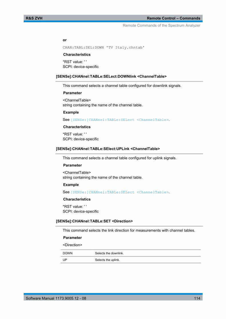
R&S ZVH Remote Control – Commands
Remote Commands of the Spectrum Analyzer
Software Manual 1173.9005.12 - 08 114
or
CHAN:TABL:SEL:DOWN 'TV Italy.chntab'
Characteristics
*RST value: ' ' SCPI: device-specific
[SENSe]:CHANnel:TABLe:SELect:DOWNlink <ChannelTable>
This command selects a channel table configured for downlink signals.
Parameter
<ChannelTable> string containing the name of the channel table.
Example
See [SENSe:]CHANnel:TABLe:SELect <ChannelTable>.
Characteristics
*RST value: ' ' SCPI: device-specific
[SENSe]:CHANnel:TABLe:SElect:UPLink <ChannelTable>
This command selects a channel table configured for uplink signals.
Parameter
<ChannelTable> string containing the name of the channel table.
Example
See [SENSe:]CHANnel:TABLe:SELect <ChannelTable>.
Characteristics
*RST value: ' ' SCPI: device-specific
[SENSe]:CHANnel:TABLe:SET <Direction>
This command selects the link direction for measurements with channel tables.
Parameter
<Direction>
DOWN Selects the downlink.
UP Selects the uplink.

R&S ZVH Remote Control – Commands
Remote Commands of the Spectrum Analyzer
Software Manual 1173.9005.12 - 08 115
Example
See [SENSe:]CHANnel:TABLe:SELect <ChannelTable>.
Characteristics
*RST value: UP SCPI: device-specific
7.3.8.2 Power Measurements
The following commands configure power measurements. To perform the actual measurement, use the commands described in section "Performing and Triggering Measurements".
List of commands
● CALCulate:MARKer:FUNCtion:POWer:SELect <Measurement> (p. 115) ● CALCulate:MARKer:FUNCtion:POWer[:STATe] <State> (p. 115) ● CALCulate:MARKer:FUNCtion:POWer:PRESet <Standard> (p. 116) ● CALCulate:MARKer:FUNCtion:POWer:PRESet:CHECk? (p. 116) ● CALCulate:MARKer:FUNCtion:LEVel:ONCE (p. 117) ● CALCulate:MARKer:FUNCtion:POWer:RESult? <Measurement> (p. 117)
CALCulate:MARKer:FUNCtion:POWer:SELect <Measurement>
This command selects a power measurement and turns the measurement on.
Parameter
ACPower | MCACpower
Adjacent Channel Leakage Ratio measurement (ACLR or ACP)
CPOWer Chanel power measurement
OBANdwidth | OBWidth
Occupied Bandwidth measurement
TDMA TDMA power measurement
Example
CALC:MARK:FUNC:POW:SEL CPOW Selects the channel power measurement
Characteristics
*RST value: – SCPI: device–specific
CALCulate:MARKer:FUNCtion:POWer[:STATe] <State>
This command turns a power measurement on and off.
You can select a power measurement with CALCulate:MARKer:FUNCtion:POWer:SELect <Measurement>.

R&S ZVH Remote Control – Commands
Remote Commands of the Spectrum Analyzer
Software Manual 1173.9005.12 - 08 116
Parameter
ON Turns the power measurement on.
OFF Performs a basic spectrum measurement.
Example
CALC:MARK:FUNC:POW OFF Switches off the power measurement.
Characteristics
*RST value: OFF SCPI: device–specific
CALCulate:MARKer:FUNCtion:POWer:PRESet <Standard>
This command selects one of the predefined configurations for a telecommunications standard. This command only works if you have turned on power measurements with CALCulate:MARKer:FUNCtion:POWer[:STATe] <State>.
The configuration for a standard is in line with the specifications and includes parameters like weighting filter, channel bandwidth and spacing, resolution and video bandwidth, as well as detector and sweep time.
Parameter
<Standard> string containing the file name of the standard
Example
CALC:MARK:FUNC:POW:PRES '3GPP WCDMA.chpstd' Selects the 3GPP WCDMA standard for channel power measurements.
Characteristics
*RST value: - SCPI: device-specific
CALCulate:MARKer:FUNCtion:POWer:PRESet:CHECk?
This command checks if the current settings are in line with the settings defined by the standard selected with CALCulate:MARKer:FUNCtion:POWer:PRESet <Standard>.
Note that the command only checks those parameters that are defined by the standard.
This command is a query and therefore has no *RST value.
Return value
0 R&S ZVH settings violate a standard configuration.
1 R&S ZVH settings comply with the standard.
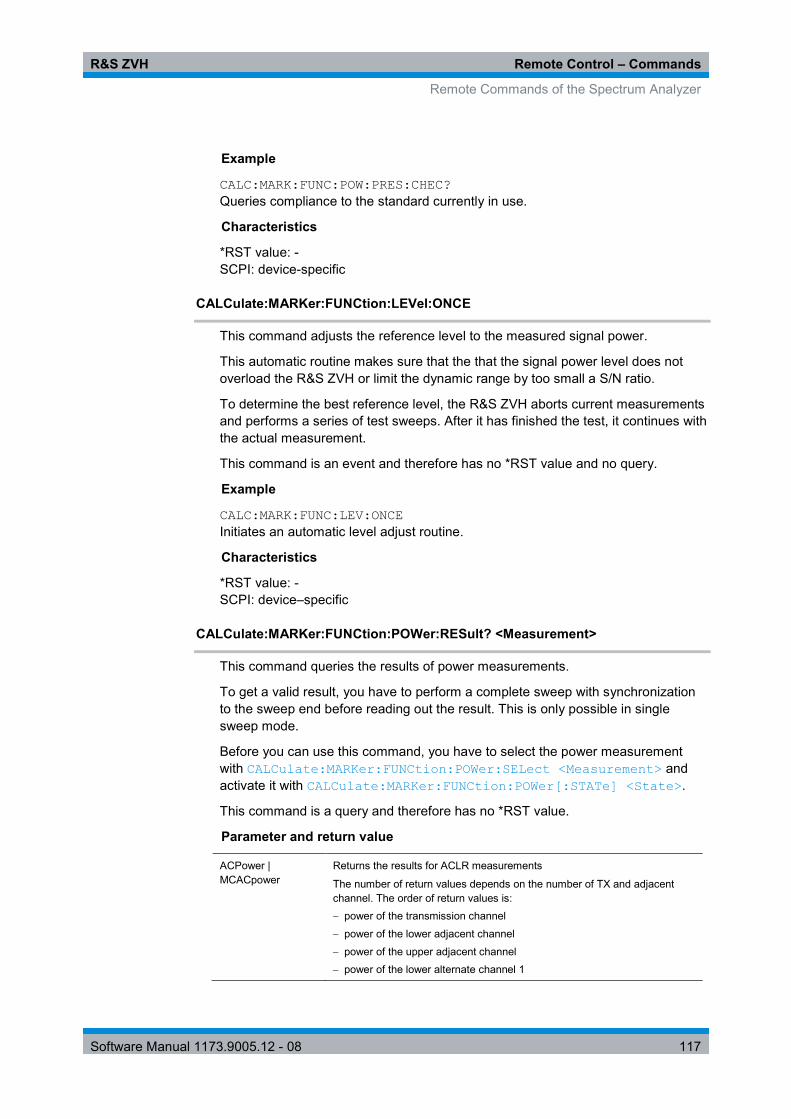
R&S ZVH Remote Control – Commands
Remote Commands of the Spectrum Analyzer
Software Manual 1173.9005.12 - 08 117
Example
CALC:MARK:FUNC:POW:PRES:CHEC? Queries compliance to the standard currently in use.
Characteristics
*RST value: - SCPI: device-specific
CALCulate:MARKer:FUNCtion:LEVel:ONCE
This command adjusts the reference level to the measured signal power.
This automatic routine makes sure that the that the signal power level does not overload the R&S ZVH or limit the dynamic range by too small a S/N ratio.
To determine the best reference level, the R&S ZVH aborts current measurements and performs a series of test sweeps. After it has finished the test, it continues with the actual measurement.
This command is an event and therefore has no *RST value and no query.
Example
CALC:MARK:FUNC:LEV:ONCE Initiates an automatic level adjust routine.
Characteristics
*RST value: - SCPI: device–specific
CALCulate:MARKer:FUNCtion:POWer:RESult? <Measurement>
This command queries the results of power measurements.
To get a valid result, you have to perform a complete sweep with synchronization to the sweep end before reading out the result. This is only possible in single sweep mode.
Before you can use this command, you have to select the power measurement with CALCulate:MARKer:FUNCtion:POWer:SELect <Measurement> and activate it with CALCulate:MARKer:FUNCtion:POWer[:STATe] <State>.
This command is a query and therefore has no *RST value.
Parameter and return value
ACPower | MCACpower
Returns the results for ACLR measurements
The number of return values depends on the number of TX and adjacent channel. The order of return values is: − power of the transmission channel
− power of the lower adjacent channel
− power of the upper adjacent channel − power of the lower alternate channel 1

R&S ZVH Remote Control – Commands
Remote Commands of the Spectrum Analyzer
Software Manual 1173.9005.12 - 08 118
− power of the upper alternate channel 2
− etc.
The unit of the return values depends on the scaling of the vertical axis: − logarithmic scaling returns the power in the currently selected unit (see UNIT:POWer).
− linear scaling returns the power in W.
CPOWer Returns the results for channel power measurements
The return value is the power of the channel. The unit depends on the scaling of the vertical axis:
− logarithmic scaling returns the power in the currently selected unit (see UNIT:POWer).
− linear scaling returns the power in W.
OBANdwidth | OBWidth
Returns the results for measurements of the occupied bandwidth.
The return value is the occupied bandwidth in Hz.
TDMA Returns the results for TDMA power measurements.
The return value is the power of the signal. The unit depends on the scaling of the vertical axis: − logarithmic scaling returns the power in the currently selected unit (see UNIT:POWer).
− linear scaling returns the power in W.
Example of occupied bandwidth measurement
POW:BAND 90PCT Defines the occupied bandwidth (90%).
INIT:CONT OFF INIT;*WAI CALC:MARK:FUNC:POW:RES? OBW Turns on single sweep mode, performs a measurement and queries the results.
Characteristics
*RST value: - SCPI: device–specific
7.3.8.3 Measuring the Channel Power
The following commands configure channel power measurements. To perform the actual measurement, use the commands described in section "Performing and Triggering Measurements".
The suffix <m> at MARKer is irrelevant.
List of commands
● CALCulate:MARKer<m>:FUNCtion:CPOWer:BANDwidth <Bandwidth> (p. 119) ● CALCulate:MARKer<m>:FUNCtion:CPOWer:MODE <DisplayMode> (p. 119) ● CALCulate:MARKer<m>:FUNCtion:CPOWer:UNIT <Unit> (p. 119) ● CALCulate:MARKer<m>:FUNCtion:POWer:RESult:PHZ <State> (p. 120)

R&S ZVH Remote Control – Commands
Remote Commands of the Spectrum Analyzer
Software Manual 1173.9005.12 - 08 119
CALCulate:MARKer<m>:FUNCtion:CPOWer:BANDwidth <Bandwidth>
This command defines the channel bandwidth for channel power measurements.
Parameter
<Bandwidth> Numeric value in Hz.
Example
CALC:MARK:FUNC:CPOW:BAND 4 MHZ Sets the channel bandwidth to 4 MHz.
Characteristics
*RST value: 3.84 MHz SCPI: device-specific
CALCulate:MARKer<m>:FUNCtion:CPOWer:MODE <DisplayMode>
This command selects the display mode for channel power measurements.
Parameter
<DisplayMode>
CLR Displays the currently measured value (Clear / Write).
MAX Displays the highest measured value (Max Hold).
Example
CALC:MARK:FUNC:CPOW:MODE CLR Selects clear/write trace mode
Characteristics
*RST value: CLR SCPI: device-specific
CALCulate:MARKer<m>:FUNCtion:CPOWer:UNIT <Unit>
This command selects the unit of the vertical axis for channel power measurements.
Parameter
<Unit> DBM | DBMV | DBUV | VOLT | WATT | V | W
Example
CALC:MARK:FUNC:CPOW:UNIT DBM Sets the unit to dBm.

R&S ZVH Remote Control – Commands
Remote Commands of the Spectrum Analyzer
Software Manual 1173.9005.12 - 08 120
Characteristics
*RST value: dBm SCPI: device-specific
CALCulate:MARKer<m>:FUNCtion:POWer:RESult:PHZ <State>
This command turns the display of the channel power per Hertz on and off.
Parameter
ON | OFF
Example
CALC:MARK:FUNC:POW:RES:PHZ ON Displays the measured Channel Power / Hz.
Characteristics
*RST value: dBm SCPI: device-specific
7.3.8.4 Measuring the Occupied Bandwidth
The following commands configure the measurement of the Occupied Bandwidth. To perform the actual measurement, use the commands described in section "Performing and Triggering Measurements".
The suffix <m> at MARKer is irrelevant.
List of commands
● CALCulate:MARKer<m>:FUNCtion:OBAN:BANDwidth <Bandwidth> (p. 120) ● CALCulate:MARKer<m>:FUNCtion:OBAN:BANDwidth:PCT <OBW> (p. 121)
CALCulate:MARKer<m>:FUNCtion:OBAN:BANDwidth <Bandwidth>
This command defines the channel bandwidth for occupied bandwidth measurements.
Instead of OBANwidth, you can also use the alias OBWidth
Parameter
<Bandwidth Numeric value in Hz.
Example
CALC:MARK:FUNC:OBW:BAND 1 MHZ Sets the channel bandwidth to 1 MHz
Characteristics
*RST value: 3.84 MHz SCPI: device-specific

R&S ZVH Remote Control – Commands
Remote Commands of the Spectrum Analyzer
Software Manual 1173.9005.12 - 08 121
CALCulate:MARKer<m>:FUNCtion:OBAN:BANDwidth:PCT <OBW>
This command defines the percentage of the total power that defines the occupied bandwidth.
Instead of OBANwidth, you can also use the alias OBWidth
Parameter
<Percentage> Numeric value in the range from 10% to 99.9%.
Example
CALC:MARK:FUNC:OBW:BAND:PCT 95 Sets the power percentage to 95%
Characteristics
*RST value: 99% SCPI: device-specific
7.3.8.5 TDMA Measurements
The following commands configure TDMA measurements. To perform the actual measurement, use the commands described in section "Performing and Triggering Measurements".
The suffix <m> at MARKer is irrelevant.
List of commands
● CALCulate:MARKer<m>:FUNCtion:TDMA:BURSt <BurstLength> (p. 121)
CALCulate:MARKer<m>:FUNCtion:TDMA:BURSt <BurstLength>
This command defines the burst length of the TDMA signal.
Parameter
<BurstLength> Numeric value in seconds.
The value range depends on the current sweep time.
Example
CALC:MARK:FUNC:TDMA:BURS 80 US Sets the burst length to 80 us.
Characteristics
*RST value: 470 us SCPI: device-specific

R&S ZVH Remote Control – Commands
Remote Commands of the Spectrum Analyzer
Software Manual 1173.9005.12 - 08 122
7.3.8.6 Measuring the Adjacent Channel Leakage Ratio
The following commands configures Adjacent Channel Leakage Ratio (ACLR) measurements. To perform the actual measurement, use the commands described in section "Performing and Triggering Measurements".
The suffix <y> selects one of the 11 alternate channels. The range is <1…11>.
The suffix <k> at LIMit is irrelevant.
● Configuring and Performing the ACLR Measurement on page 122 ● ACLR Limit Check on page 128
Configuring and Performing the ACLR Measurement
The following commands configure and perform the ACLR measurements.
List of commands
● CALCulate:MARKer:FUNCtion:ACPower:UNIT <Unit> (p. 122) ● [SENSe:]POWer:ACHannel:ACPairs <ChannelPairs> (p. 123) ● [SENSe:]POWer:ACHannel:BANDwidth[:CHANnel] <Bandwidth> (p. 123) ● [SENSe:]POWer:ACHannel:BANDwidth:ACHannel <Bandwidth> (p. 123) ● [SENSe:]POWer:ACHannel:BANDwidth:ALTernate<y> <Bandwidth> (p. 124) ● [SENSe:]POWer:ACHannel:MODE <PowerMode> (p. 124) ● [SENSe:]POWer:ACHannel:PRESet:RLEVel (p. 125) ● [SENSe:]POWer:ACHannel:REFerence:TXCHannel:AUTO <RefChannel> (p. 125) ● [SENSe:]POWer:ACHannel:REFerence:TXCHannel:MANual <RefChannel> (p.
125) ● [SENSe:]POWer:ACHannel:SPACing[:ACHannel] (p. 126) ● [SENSe:]POWer:ACHannel:SPACing:ALTernate<y> <Spacing> (p. 126) ● [SENSe:]POWer:ACHannel:SPACing:CHANnel<Tx> <Spacing> (p. 127) ● [SENSe:]POWer:ACHannel:TXCHannel:COUNt <TxChannels> (p. 127)
CALCulate:MARKer:FUNCtion:ACPower:UNIT <Unit>
This command selects the unit of the ACLR results.
Parameter
<Unit> DBM | DBMV | DBUV | VOLT | WATT
Example
CALC:MARK:FUNC:ACP:UNIT DBM ACLR results are converted into the unit dBm.
Characteristics
*RST value: 1 SCPI: device-specific

R&S ZVH Remote Control – Commands
Remote Commands of the Spectrum Analyzer
Software Manual 1173.9005.12 - 08 123
[SENSe:]POWer:ACHannel:ACPairs <ChannelPairs>
This command defines the number of pairs of adjacent channels.
Parameter
<ChannelPairs> Numeric value in the range from 1 to 12.
The number corresponds to a pair of adjacent channels, one channel on the left and one on the right of the transmission channel.
Example
See [SENSe:]POWer:ACHannel:TXCHannel:COUNt <TxChannels>
Characteristics
*RST value: 1 SCPI: device-specific
[SENSe:]POWer:ACHannel:BANDwidth[:CHANnel] <Bandwidth>
This command defines the channel bandwidth of the transmission channels.
Instead of BANDwidth, you can also use the alias BWIDth
Parameter
<Bandwidth> Numeric value in Hz.
Example
See [SENSe:]POWer:ACHannel:TXCHannel:COUNt <TxChannels>
Characteristics
*RST value: 14 kHz SCPI: device-specific
[SENSe:]POWer:ACHannel:BANDwidth:ACHannel <Bandwidth>
This command defines the channel bandwidth of the adjacent channel.
The adjacent channel is the first pair of channels next to the transmission channels. If you set the channel bandwidth for these channels, the R&S ZVH sets the bandwidth of the alternate channels to the same value.
Instead of BANDwidth, you can also use the alias BWIDth
Parameter
<Bandwidth> Numeric value in Hz.
Example
See [SENSe:]POWer:ACHannel:TXCHannel:COUNt <TxChannels>

R&S ZVH Remote Control – Commands
Remote Commands of the Spectrum Analyzer
Software Manual 1173.9005.12 - 08 124
Characteristics
*RST value: 14 kHz SCPI: device-specific
[SENSe:]POWer:ACHannel:BANDwidth:ALTernate<y> <Bandwidth>
This command defines the bandwidth of the alternate channels.
If you set the channel bandwidth for the first alternate channel, the R&S ZVH sets the bandwidth of the other alternate channels to the same value. The command works hierarchically: to set a bandwidth of the 10th and 8th channel, you have to set the bandwidth of the 8th channel first.
Instead of BANDwidth, you can also use the alias BWIDth
Parameter
<Bandwidth> Numeric value in Hz.
Example
See [SENSe:]POWer:ACHannel:TXCHannel:COUNt <TxChannels>
Characteristics
*RST value: 14 kHz SCPI: device-specific
[SENSe:]POWer:ACHannel:MODE <PowerMode>
This command selects the way the R&S ZVH displays the power of adjacent channels.
The number of adjacent and alternate channels has to be greater than 0 for the command to work.
Parameter
<PowerMode>
ABSolute Shows the absolute power of all channels..
RELative Shows the power of adjacent and alternate channels in relation to the transmission channel.
Example
POW:ACH:MODE ABS Shows absolute powers for all channels.
Characteristics
*RST value SCPI: device-specific

R&S ZVH Remote Control – Commands
Remote Commands of the Spectrum Analyzer
Software Manual 1173.9005.12 - 08 125
[SENSe:]POWer:ACHannel:PRESet:RLEVel
This command adjusts the reference level to the measured signal power.
This automatic routine makes sure that the that the signal power level does not overload the R&S ZVH or limit the dynamic range by too small a S/N ratio.
To determine the best reference level, the R&S ZVH aborts current measurements and performs a series of test sweeps. After it has finished the test, it continues with the actual measurement.
This command is an event and therefore has no *RST value and no query.
Example
POW:ACH:PRES:RLEV Initiates an ACP measurement and adjusts the reference level.
Characteristics
*RST value: - SCPI: device-specific
[SENSe:]POWer:ACHannel:REFerence:TXCHannel:AUTO <RefChannel>
This command automatically selects a reference channel for relative ACLR measurements.
The number of transmission channels and adjacent / alternate channels has to be greater than 0 for the command to work.
Parameter
<RefChannel>
MINimum Reference is the transmission channel with the lowest power.
MAXimum Reference is the transmission channel with the highest power.
LHIGest Reference is the lowest transmission channel for lower adjacent channels and highest transmission channel for upper adjacent channels.
Example
POW:ACH:REF:TXCH:AUTO MIN Sets the TX channel with the lowest power as reference channel
Characteristics
*RST value SCPI: device-specific
[SENSe:]POWer:ACHannel:REFerence:TXCHannel:MANual <RefChannel>
This command defines a reference channel for relative ACLR measurements.
The number of transmission channels and adjacent / alternate channels has to be greater than 0 for the command to work.

R&S ZVH Remote Control – Commands
Remote Commands of the Spectrum Analyzer
Software Manual 1173.9005.12 - 08 126
Parameter
<RefChannel> Numeric value from 1 to 12.
The actual value range depends on the number of active transmission channels.
Example
See [SENSe:]POWer:ACHannel:TXCHannel:COUNt <TxChannels>
Characteristics
*RST value: 1 SCPI: device-specific
[SENSe:]POWer:ACHannel:SPACing[:ACHannel]] <Spacing>
This command defines the spacing between the transmission channel and its adjacent channel.
A change of the adjacent channel spacing causes a change in the spacing of all alternate channels above the adjacent channel.
Parameter
<Spacing> Numeric value in Hz.
Example
See [SENSe:]POWer:ACHannel:TXCHannel:COUNt <TxChannels>
Characteristics
*RST value: 14 kHz SCPI: device-specific
[SENSe:]POWer:ACHannel:SPACing:ALTernate<y> <Spacing>
This command defines the spacing between alternate channels.
If you set the channel spacing for the first alternate channel, the R&S ZVH sets the bandwidth of the other alternate channels to the same value. The command works hierarchically: to set a spacing of the 10th and 8th channel, you have to set the spacing of the 8th channel first.
Parameter
<Spacing> Numeric value in Hz.
Example
See [SENSe:]POWer:ACHannel:TXCHannel:COUNt <TxChannels>
Characteristics
*RST value: ALT1: 40 kHz; ALT2: 60 kHz; ALT3: 80 kHz etc. SCPI: device-specific

R&S ZVH Remote Control – Commands
Remote Commands of the Spectrum Analyzer
Software Manual 1173.9005.12 - 08 127
[SENSe:]POWer:ACHannel:SPACing:CHANnel<Tx> <Spacing>
This command defines the spacing between transmission channels.
If you set the channel spacing for the first transmission channel, the R&S ZVH sets the bandwidth of the other transmission channels to the same value. The command works hierarchically: to set a spacing between the 9th and 10th and 8th and 9th channel, you have to set the spacing between the 8th and 9th channel first.
The suffix at CHANnel selects the transmission channel.
Parameter
<Spacing> Numeric value in Hz.
Example
See [SENSe:]POWer:ACHannel:TXCHannel:COUNt <TxChannels>
Characteristics
*RST value: 20 kHz SCPI: device-specific
[SENSe:]POWer:ACHannel:TXCHannel:COUNt <TxChannels>
This command defines the number of transmission channels.
The command is available for measurements with span > 0.
Parameter
<TxChannels> Numeric value from 1 to 12.
Example
CALC:MARK:FUNC:POW:SEL CPOW Selects the channel power measurement
POW:ACH:TXCH:COUN 2 Defines 2 transmission channels.
POW:ACH:ACP 2 Defines 2 pairs of neighboring channels to the left and right of the TX channel(s).
POW:ACH:SPAC:CHAN2 20KHZ Defines a distance of 20 kHz between the first and the second Tx channel.
POW:ACH:BAND:CHAN2 120KHZ Defines a bandwidth of 120 kHz for the second TX channel.
POW:ACH:REF:TXCH:MAN 2 Selects the second Tx channel as reference channel.
POW:ACH:SPAC 10KHZ Defines a distance of 10 kHz from the TX channel to the adjacent channel.

R&S ZVH Remote Control – Commands
Remote Commands of the Spectrum Analyzer
Software Manual 1173.9005.12 - 08 128
POW:ACH:BAND:ACH 120KHZ Defines a bandwidth of 120 kHz for the adjacent channel.
POW:ACH:SPAC:ALT 20KHZ Defines a distance of 20 kHz from the adjacent to the first alternate channel.
POW:ACH:BAND:ALT 120KHZ Defines a bandwidth of 120 kHz for the first alternate channel
Characteristics
*RST value: 1 SCPI: device-specific
ACLR Limit Check
The following commands configure and perform limit checks when measuring the adjacent channel power.
The suffix <k> at LIMit is irrelevant.
List of commands
● CALCulate:LIMit<k>:ACPower[:STATe] <State> (p. 128) ● CALCulate:LIMit<k>:ACPower:ACHannel[:RELative] <Limit> (p. 129) ● CALCulate:LIMit<k>:ACPower:ACHannel[:RELative]:STATe <State> (p. 129) ● CALCulate:LIMit<k>:ACPower:ACHannel:ABSolute <Limit> (p. 130) ● CALCulate:LIMit<k>:ACPower:ACHannel:ABSolute:STATe <State> (p. 130) ● CALCulate:LIMit<k>:ACPower:ACHannel:RESult? (p. 130) ● CALCulate:LIMit<k>:ACPower:ALTernate<y>[:RELative] <Limit> (p. 131) ● CALCulate:LIMit<k>:ACPower:ALTernate<y>[:RELative]:STATe <State> (p. 131) ● CALCulate:LIMit<k>:ACPower:ALTernate<y>:ABSolute <Limit> (p. 132) ● CALCulate:LIMit<k>:ACPower:ALTernate<y>:ABSolute:STATe <State> (p. 132) ● CALCulate:LIMit<k>:ACPower:ALTernate<y>:RESult? (p. 133)
CALCulate:LIMit<k>:ACPower[:STATe] <State>
This command turns the limit check for ACLR measurements on and off.
You have to use CALCulate:LIMit<k>:ACPower:ACHannel[:RELative]:STATe <State> or CALCulate:LIMit<k>:ACPower:ALTernate<y>[:RELative]:STATe <State> in combination with this command to select the channels the limit check should be performed on.
Parameter
<State> ON | OFF
Example
CALC:LIM:ACP ON Activates the limit check

R&S ZVH Remote Control – Commands
Remote Commands of the Spectrum Analyzer
Software Manual 1173.9005.12 - 08 129
Characteristics
*RST value: OFF SCPI: device-specific
CALCulate:LIMit<k>:ACPower:ACHannel[:RELative] <Limit>
This command defines the relative limit of the adjacent channels. The reference value for the relative limit value is the measured channel power.
Note that the relative limit has no effect on the limit check if it is below the absolute limit value (see CALCulate:LIMit<k>:ACPower:ACHannel:ABSolute <Limit>). This mechanism allows automatic checking of the absolute basic values of adjacent-channel power as defined in mobile radio standards.
Parameter
<Limit> Numeric value in the range from 0 dB to 100 dB.
Example
CALC:LIM:ACP:ACH 30 Defines a limit of 30 dB.
Characteristics
*RST value: - SCPI: device-specific
CALCulate:LIMit<k>:ACPower:ACHannel[:RELative]:STATe <State>
This command turns the relative limit check for the adjacent channels on and off.
You have to activate the general ACLR limit check before using this command with CALCulate:LIMit<k>:ACPower[:STATe] <State> first.
Parameter
<State> ON | OFF
Example
CALC:LIM:ACP:ACH:STAT ON Activates the relative limit check.
Characteristics
*RST value: OFF SCPI: device-specific

R&S ZVH Remote Control – Commands
Remote Commands of the Spectrum Analyzer
Software Manual 1173.9005.12 - 08 130
CALCulate:LIMit<k>:ACPower:ACHannel:ABSolute <Limit>
This command defines the absolute limit for the adjacent channels.
Note that the absolute limit has no effect on the limit check if it is below the relative limit (see CALCulate:LIMit<k>:ACPower:ACHannel[:RELative] <Limit>). This mechanism allows automatic checking of the absolute basic values of adjacent-channel power as defined in mobile radio standards.
Parameter
<Limit> Numeric value in the range from -200 dBm to 200 dBm.
Example
CALC:LIM:ACP:ACH:ABS -30 Sets the absolute limit to -30 dBm
Characteristics
*RST value: - SCPI: device-specific
CALCulate:LIMit<k>:ACPower:ACHannel:ABSolute:STATe <State>
This command turns the absolute limit check for the adjacent channel on and off.
You have to activate the general ACLR limit check before using this command with CALCulate:LIMit<k>:ACPower[:STATe] <State> first.
Parameter
<State> ON | OFF
Example
CALC:LIM:ACP:ACH:ABS:STAT ON Activates the absolute limit check.
Characteristics
*RST value: OFF SCPI: device-specific
CALCulate:LIMit<k>:ACPower:ACHannel:RESult?
This command queries the result of the limit check of the adjacent channels.
To get a valid result, you have to perform a complete sweep with synchronization to the sweep end before reading out the result. This is only possible in single sweep mode.
This command is a query and therefore has no *RST value.

R&S ZVH Remote Control – Commands
Remote Commands of the Spectrum Analyzer
Software Manual 1173.9005.12 - 08 131
Return value
The return value consists of two values, one for the lower and one for the upper adjacent channel.
FAILed Limit check failed.
PASSed Limit check passed.
Example
CALC:LIM:ACP:ACH:RES? Queries the limit check results. The command would return, e.g.
FAILED,FAILED Upper and lower adjacent channels violate a limit.
Characteristics
*RST value: - SCPI: device-specific
CALCulate:LIMit<k>:ACPower:ALTernate<y>[:RELative] <Limit>
This command defines the relative limit of the alternate channels. The reference value for the relative limit value is the measured channel power.
Note that the relative limit has no effect on the limit check if it is below the absolute limit value (see CALCulate:LIMit<k>:ACPower:ALTernate<y>:ABSolute <Limit>). This mechanism allows automatic checking of the absolute basic values of adjacent-channel power as defined in mobile radio standards.
Parameter
<Limit> Numeric value in the range from 0 dB to 100 dB.
Example
CALC:LIM:ACP:ALT3 30 Defines a limit of 30 dB for the third alternate channel.
Characteristics
*RST value: - SCPI: device-specific
CALCulate:LIMit<k>:ACPower:ALTernate<y>[:RELative]:STATe <State>
This command turns the relative limit check for an alternate channels on and off.
You have to activate the general ACLR limit check before using this command with CALCulate:LIMit<k>:ACPower[:STATe] <State> first.
Parameter
<State> ON | OFF

R&S ZVH Remote Control – Commands
Remote Commands of the Spectrum Analyzer
Software Manual 1173.9005.12 - 08 132
Example
CALC:LIM:ACP:ALT3:STAT ON Activates the relative limit check for the third alternate channel.
Characteristics
*RST value: OFF SCPI: device-specific
CALCulate:LIMit<k>:ACPower:ALTernate<y>:ABSolute <Limit>
This command defines the absolute limit for the alternate channels.
Note that the absolute limit has no effect on the limit check if it is below the relative limit (see CALCulate:LIMit<k>:ACPower:ALTernate<y>[:RELative] <Limit>). This mechanism allows automatic checking of the absolute basic values of adjacent-channel power as defined in mobile radio standards.
Parameters
<Limit> Numeric value in the range from -200 dBm to 200 dBm.
Example
CALC:LIM:ACP:ALT3:ABS -30 Sets the absolute limit to -30 dBm for the third alternate channel.
Characteristics
*RST value: - SCPI: device-specific
CALCulate:LIMit<k>:ACPower:ALTernate<y>:ABSolute:STATe <State>
This command turns the absolute limit check for an alternate channel on and off.
You have to activate the general ACLR limit check before using this command with CALCulate:LIMit<k>:ACPower[:STATe] <State> first.
Parameter
<State> ON | OFF
Example
CALC:LIM:ACP:ALT3:ABS:STAT ON Activates the absolute limit check for the third alternate channel.
Characteristics
*RST value: OFF SCPI: device-specific

R&S ZVH Remote Control – Commands
Remote Commands of the Spectrum Analyzer
Software Manual 1173.9005.12 - 08 133
CALCulate:LIMit<k>:ACPower:ALTernate<y>:RESult?
This command queries the result of the limit check of the alternate channels.
To get a valid result, you have to perform a complete sweep with synchronization to the sweep end before reading out the result. This is only possible in single sweep mode.
This command is a query and therefore has no *RST value.
Return value
The return value consists of two values, one for the lower and one for the upper alternate channel.
FAILed Limit check failed.
PASSed Limit check passed.
Example
CALC:LIM:ACP:ALT2:RES? Queries the limit check results for the second alternate channels. The command would return, e.g.
FAILED,FAILED Upper and lower alternate channels violate a limit.
Characteristics
*RST value: - SCPI: device-specific
ACLR Result Query
The following commands query results specific to the adjacent channel power measurement.
The suffixes<n> and <m> at CALCulate and MARKer are irrelevant.
List of commands
● CALCulate<n>:MARKer<m>:FUNCtion:TXPower:RESult? (p. 133)
CALCulate<n>:MARKer<m>:FUNCtion:TXPower:RESult?
This command queriesthe total TX channel power.
(Use CALCulate:MARKer:FUNCtion:POWer:RESult? <Measurement> to query the power of each TX channel.)
Return value
<Power>

R&S ZVH Remote Control – Commands
Remote Commands of the Spectrum Analyzer
Software Manual 1173.9005.12 - 08 134
Example
CALC:MARK:FUNC:TXP:RES? Queries the total channel power over all TX channels.
Characteristics
*RST value: - SCPI: device-specific
7.3.8.7 Measuring the Harmonic Distortion
The following commands configure Harmonic Distortion measurements. To perform the actual measurement, use the commands described in section "Performing and Triggering Measurements".
The numeric suffixes <n> and <m> at CALCulate and MARKer are irrelevant.
List of commands
● CALCulate<n>:MARKer<m>:FUNCtion:HARMonics[:STATe] <State> (p. 134) ● CALCulate<n>:MARKer<m>:FUNCtion:HARMonics:DISTortion? (p. 134) ● CALCulate<n>:MARKer<m>:FUNCtion:HARMonics:LIST? (p. 135) ● CALCulate<n>:MARKer<m>:FUNCtion:HARMonics:NHARmonics <Harmonics>
(p. 135) ● CALCulate<n>:MARKer<m>:FUNCtion:HARMonics:PRESet (p. 136)
CALCulate<n>:MARKer<m>:FUNCtion:HARMonics[:STATe] <State>
This command turns the harmonic distortion measurement on and off.
Parameter
<State> ON | OFF
Example
See CALCulate<n>:MARKer<m>:FUNCtion:HARMonics:PRESet.
Characteristics
*RST value: OFF SCPI: device-specific
CALCulate<n>:MARKer<m>:FUNCtion:HARMonics:DISTortion? TOTal
This command queries the total harmonic distortion of the signal.
To get a valid result, you have to perform a complete sweep with synchronization to the sweep end before reading out the result. This is only possible in single sweep mode.
This command is a query and therefore has no *RST value.

R&S ZVH Remote Control – Commands
Remote Commands of the Spectrum Analyzer
Software Manual 1173.9005.12 - 08 135
Parameter
TOTal
Return value
<Distortion%>,<DistortiondB>
Pair of values, one showing the THD in %, one in dB.
Example
See CALCulate<n>:MARKer<m>:FUNCtion:HARMonics:PRESet.
Characteristics
*RST value: - SCPI: device-specific
CALCulate<n>:MARKer<m>:FUNCtion:HARMonics:LIST?
This command queries the position of the harmonics.
To get a valid result, you should perform a complete sweep in single sweep mode before querying the results.
This command is a query and therefore has no *RST value.
Return value
Returns one value for every harmonic.
The first value is the absolute power of the first harmonic. The level unit depends on the unit you have set with the UNIT:POWer command. The other values are power levels relative to the first harmonic. The unit for these is dB.
The total number of return values depends on the number of harmonics you have set with CALCulate<n>:MARKer<m>:FUNCtion:HARMonics:NHARmonics <Harmonics>.
Example
See CALCulate<n>:MARKer<m>:FUNCtion:HARMonics:PRESet.
Characteristics
*RST value: - SCPI: device-specific
CALCulate<n>:MARKer<m>:FUNCtion:HARMonics:NHARmonics <Harmonics>
This command sets the number of harmonics. The valid range is from 1 to 6 harmonics.
Parameter
<Harmonics> Numeric value in the range from 1 to 6.

R&S ZVH Remote Control – Commands
Remote Commands of the Spectrum Analyzer
Software Manual 1173.9005.12 - 08 136
Example
See CALCulate<n>:MARKer<m>:FUNCtion:HARMonics:PRESet.
Characteristics
*RST value: 2 SCPI: device-specific
CALCulate<n>:MARKer<m>:FUNCtion:HARMonics:PRESet
This command optimizes the settings for the harmonic distortion measurement.
This command is an event and therefore has no query and no *RST value.
Example
CALC:MARK:FUNC:HARM ON Activates the harmonic distortion measurement.
CALC:MARK:FUNC:HARM:NHAR 4 Sets the number of harmonics to 4.
CALC:MARK:FUNC:HARM:PRES Adjusts the settings of the measurement.
CALC:MARK:FUNC:HARM:LIST? CALC:MARK:FUNC:HARM:DIST? TOT Queries the position of the harmonics and the total harmonic distortion.
Characteristics
*RST value: - SCPI: device-specific
7.3.8.8 Measuring the AM Modulation Depth
The following commands configure AM Modulation Depth measurements. To perform the actual measurement, use the commands described in section "Performing and Triggering Measurements".
The numeric suffixes <n> and <m> at CALCulate and MARKer are irrelevant.
List of commands
● CALCulate<n>:MARKer<m>:FUNCtion:MDEPth[:STATe] <State> (p. 136) ● CALCulate<n>:MARKer<m>:FUNCtion:MDEPth:RESult? (p. 137)
CALCulate<n>:MARKer<m>:FUNCtion:MDEPth[:STATe] <State>
This command turns the AM Modulation Depth measurement on and off.
The numeric suffixes at CALCulate and MARKer are irrelevant.

R&S ZVH Remote Control – Commands
Remote Commands of the Spectrum Analyzer
Software Manual 1173.9005.12 - 08 137
Parameter
<State> ON | OFF
Example
CALC:MARK:FUNC:MDEP ON Activates the harmonic distortion measurement.
Characteristics
*RST value: OFF SCPI: device-specific
CALCulate<n>:MARKer<m>:FUNCtion:MDEPth:RESult?
This command queries the results of the AM modulation depth measurement.
This command is a query and therefore has no *RST value.
Return value
<ModulationDepth> Modulation depth in %.
Example
CALC:MARK:FUNC:MDEP:RES? Queries the AM modulation depth.
Characteristics
*RST value: - SCPI: device-specific
7.3.8.9 Measuring the Spectrum Emission Mask
The following commands configure Spectrum Emission Mask (SEM) measurements. To perform the actual measurement, use the commands described in section "Performing and Triggering Measurements".
List of commands
● [SENSe:]ESPectrum:PRESet[:STANdard] <Standard> (p. 138) ● [SENSe:]ESPectrum:PRESet:SETTings (p. 138) ● [SENSe:]SWEep:MODE <State> (p. 139) ● CALCulate<n>:MARKer<m>:FUNCtion:TXPower:RESult? (p. 137)
CALCulate<n>:MARKer<m>:FUNCtion:TXPower:RESult?
This command queries the TX channel power.
Return value
<Power>

R&S ZVH Remote Control – Commands
Remote Commands of the Spectrum Analyzer
Software Manual 1173.9005.12 - 08 138
The power is either the peak power or the channel power,depending on the selected standard.
Example
CALC:MARK:FUNC:TXP:RES? Queries the total channel power over all TX channels.
Characteristics
*RST value: - SCPI: device-specific
[SENSe:]ESPectrum:PRESet[:STANdard] <Standard>
This command loads one of the predefined spectrum emission masks for a telecommunications standard.
Parameter
<Standard> String containing the file name of the spectrum emission mask.
Example
ESP:PRES 'W-CDMA 3GPP.semstd' Loads the SEM for 3GPP WCDMA.
Characteristics
*RST value: - SCPI: device-specific
[SENSe:]ESPectrum:PRESet:SETTings ONCE
This command optimizes the settings for the SEM measurement.
This command is an event and therefore has no query and no *RST value.
Parameter
ONCE
Example
ESP:PRES:SET ONCE Initializes an adjustment of the settings.
Characteristics
*RST value: - SCPI: device-specific

R&S ZVH Remote Control – Commands
Remote Commands of the Spectrum Analyzer
Software Manual 1173.9005.12 - 08 139
[SENSe:]SWEep:MODE <State>
This command turns the spectrum emission mask measurement on and off.
Parameter
AUTO Turns on the Spectrum mode.
ESPectrum Turns on the SEM measurement.
LIST Turns on the Spurious Emission measurement.
Example
SWE:MODE ESP Starts the SEM measurement.
Characteristics
*RST value: AUTO SCPI: device-specific
7.3.8.10 Measuring Spurious Emissions
The following commands configure Spurious Emission measurements. To perform the actual measurement, use the commands described in section "Performing and Triggering Measurements".
List of commands
● [SENSe:]FREQuency:CARRier:STARt <Frequency> (p. 139) ● [SENSe:]FREQuency:CARRier:STOP <Frequency> (p. 140) ● [SENSe:]SWEep:MODE <State> (p. 139)
[SENSe:]FREQuency:CARRier:STARt <Frequency> This command defines the start frequency of the 3GPP carrier.
Parameter
<Frequency> Numeric value in Hz.
Example
FREQ:CARR:STAR 1910MHZ Defines a carrier start frequency of 1910 MHz.
Characteristics
*RST value: - SCPI: device-specific

R&S ZVH Remote Control – Commands
Remote Commands of the Spectrum Analyzer
Software Manual 1173.9005.12 - 08 140
[SENSe:]FREQuency:CARRier:STOP <Frequency> This command defines the start frequency of the 3GPP carrier.
Parameter
<Frequency> Numeric value in Hz.
Example
FREQ:CARR:STOP 1990MHZ Defines a carrier stop frequency of 1990 MHz.
Characteristics
*RST value: - SCPI: device-specific
7.3.8.11 Using an Isotropic Antenna
This chapter describes all commands available to set up measurements with an isotropic antenna.
You can use an isotropic antenna with all measurement modes that are described above.
List of commands
● INPut:ANTenna:MEASure <Direction> (p. 140) ● INPut:ANTenna:STATe <State> (p. 141) ● [SENSe:]CORRection:TRANsducer<t>:ISOTropic[:STATe]? (p. 141)
INPut:ANTenna:MEASure <Direction>
This command selects the direction that the isotropic antenna measures.
Parameter
<Direction>
AUTO Automatically selects the direction.
X | Y | Z Measures the corresponding direction only.
Example
INP:ANT:MEAS X Measures in x-direction.
Characteristics
*RST value: AUTO SCPI: device-specific

R&S ZVH Remote Control – Commands
Remote Commands of the Spectrum Analyzer
Software Manual 1173.9005.12 - 08 141
INPut:ANTenna:STATe <State>
This command turns the use of an isotropic antenna on and off.
Parameter
<State> ON | OFF
Example
INP:ANT:STAT ON Activates the isotropic antenna
Characteristics
*RST value: OFF SCPI: device-specific
[SENSe:]CORRection:TRANsducer<t>:ISOTropic[:STATe]?
This command queries if the currently selected transducer is an isotropic antenna.
When you use the command for 3GPP WCDMA measurements in the Digital Modulation operating mode, the command also turns the use of an isotropic antenna on and off.
The numeric suffix <t> at TRANsducer selects the primary or secondary transducer and is in the range <1…2>.
Return values
0 Transducer is not an isotropic antenna.
1 Transducer is an isotropic antenna.
Example
CORR:TRAN:ISOT?
Characteristics
*RST value: - SCPI: device-specific

R&S ZVH Remote Control – Commands
Remote Commands of the Network Analyzer Mode
Software Manual 1173.9005.12 - 08 142
7.4 Remote Commands of the Network Analyzer Mode
The chapter provides information on remote commands that configure and perform two-port measurements with the tracking generator. These commands are available in network analyzer mode only.
Availability of remote commands for the Network Analyzer Note that some of the listed remote commands take effect only if options R&S ZVH-K42 Vector Reflection and Transmission Measurements and / or R&S ZVH-K45 Vector Voltmeter are installed.
Contents
Configuring the Horizontal Axis on page 142 Configuring the Vertical Axis on page 143 Setting the Bandwidths on page 148 Performing and Triggering the Measurement on page 148 Working with Traces on page 149 Using Markers and Deltamarkers on page 151 Configuring the Measurement on page 155
7.4.1 Configuring the Horizontal Axis
The following commands configure the horizontal axis of the active display.
List of commands
● [SENSe:]FREQuency:CENTer <Frequency> (p. 36) ● [SENSe:]FREQuency:CENTer:STEP <StepSize> (p. 36) ● [SENSe:]FREQuency:CENTer:STEP:LINK <StepSizeCoupling> (p. 37) ● [SENSe:]FREQuency:SPAN <Span> (p. 38) ● [SENSe:]FREQuency:SPAN:FULL (p. 78) ● [SENSe:]FREQuency:STARt <StartFrequency> (p. 39) ● [SENSe:]FREQuency:STOP <StopFrequency> (p. 39)
For a detailed description of the commands refer to "Configuring the Horizontal Axis" in CAT mode.

R&S ZVH Remote Control – Commands
Remote Commands of the Network Analyzer Mode
Software Manual 1173.9005.12 - 08 143
7.4.2 Configuring the Vertical Axis
The following commands configure the level axis (y-axis) and level parameters of the active display.
The suffix <n> at DISPlay selects the measurement screen in dual trace mode. The range is <1…2>.
List of commands
● DISPlay<n>:GDELay:REFerence <RefValue> (p. 143) ● DISPlay<n>:GDELay:REFerence:POSition <RefPosition> (p. 144) ● DISPlay<n>:GDELay:Y:SCALe <DisplayRange> (p. 144) ● DISPlay<n>:IMPedance:REFerence:POSition <Impedance> (p. 153) ● DISPlay<n>:LOSS:REFerence <RefValue> (p. 41) ● DISPlay<n>:LOSS:REFerence:POSition <RefPosition> (p. 42) ● DISPlay<n>:LOSS:Y:SCALe <DisplayRange> (p. 42) ● DISPlay<n>:MAGNitude:REFerence <RefValue> (p. 43) ● DISPlay<n>:MAGNitude:REFerence:POSition <RefPosition> (p. 43) ● DISPlay<n>:MAGNitude:Y:SCALe <DisplayRange> (p. 43) ● DISPlay<n>:MAGNitude:Y:SPACing <Scaling> (p. 44) ● DISPlay<n>:PHASe:REFerence <RefValue> (p. 145) ● DISPlay<n>:PHASe:REFerence:POSition <RefPosition> (p. 145) ● DISPlay<n>:PHASe:Y:SCALe <DisplayRange> (p. 145) ● DISPlay<n>:PHASe:UNWRap <State> (p. 146) ● DISPlay<n>:REFLection:Y:SCALe <DisplayRange> (p. 146) ● DISPlay<n>:REFLection:UNIT <Unit> (p. 147) ● DISPlay<n>:VSWR:Y:SCALe:MINimum <BottomValue> (p. 44) ● DISPlay<n>:VSWR:Y:SCALe:MAXimum <TopValue> (p. 45) ● DISPlay<n>:VSWR:Y:SCALe <DisplayRange> (p. 45) ● INPut:ATTenuation <Attenuation> (p. 45) ● SOURce:TG:ATTenuation <TGAttenuation> (p. 46) ● UNIT:POWer <Unit> (p. 85)
For a detailed description of commands not described below refer to "Configuring the Vertical Axis" in CAT mode and "Configuring the Vertical Axis" in spectrum mode.
DISPlay<n>:GDELay:REFerence <RefValue>
This command sets the reference value for the group delay measurement format.
Parameter
<RefValue> Numeric value in the range from 1 ns to 1000 ns.
Example
DISP:GDEL:REF 20 Sets the reference level to 20 nanoseconds

R&S ZVH Remote Control – Commands
Remote Commands of the Network Analyzer Mode
Software Manual 1173.9005.12 - 08 144
Characteristics
*RST value: 0 ns SCPI: device-specific
DISPlay<n>:GDELay:REFerence:POSition <RefPosition>
This command defines the position of the reference value on the display for the group delay measurement format.
Each step shifts the reference position one grid line up or down.
Parameter
<RefPosition> Numeric value in the range from 0 to 10.
Example
DISP:GDEL:REF:POS 1 Sets the reference to the first grid line from the bottom.
Characteristics
*RST value: 5 SCPI: device-specific
DISPlay<n>:GDELay:Y:SCALe <DisplayRange>
This command defines the display range of the vertical axis for the group delay measurement format.
Parameter
<DisplayRange> Numeric value in the range from 10 ns to 100000 ns.
The number you enter is rounded up to the next possible display range. For example, if you enter 9, the R&S ZVH automatically sets the display range to 10.
Example
DISP:GDEL:Y:SCAL 20E-9 Sets the display range to 20 nanoseconds
Characteristics
*RST value: 100 ns SCPI: device-specific

R&S ZVH Remote Control – Commands
Remote Commands of the Network Analyzer Mode
Software Manual 1173.9005.12 - 08 145
DISPlay<n>:PHASe:REFerence <RefValue>
This command sets the reference value for the phase measurement format.
Parameter
<RefValue> Numeric value in the range from -100000° to 100000°.
Example
DISP:MAGN:REF -10 Sets the reference level to -10 dB
Characteristics
*RST value: 0 dB SCPI: device-specific
DISPlay<n>:PHASe:REFerence:POSition <RefPosition>
This command defines the position of the reference value on the display for the phase measurement format.
Each step shifts the reference position one grid line up or down.
Parameter
<RefPosition> Numeric value in the range from 0 to 10.
Example
DISP:LOSS:REF:POS 5 Sets the reference to the center of the display (i.e. the fifth grid line from the bottom).
Characteristics
*RST value: 10 SCPI: device-specific
DISPlay<n>:PHASe:Y:SCALe <DisplayRange>
This command defines the display range of the vertical axis for the phase measurement format.
Parameter
<DisplayRange> Numeric value in the range from 90° to 100000°.
The number you enter is rounded up to the next possible display range. For example, if you enter 80°, the R&S ZVH automatically sets the display range to 90°.

R&S ZVH Remote Control – Commands
Remote Commands of the Network Analyzer Mode
Software Manual 1173.9005.12 - 08 146
Example
DISP:PHAS:Y:SCAL 180 Sets the display range of the phase measurement to 180°
Characteristics
*RST value: 360° SCPI: device-specific
DISPlay<n>:PHASe:UNWRap <State>
This command removes the restriction limiting the value range to +/- 180°.
Parameter
<State> ON | OFF
Example
DISP:PHAS:UNWR ON Activates the phase unwrap
Characteristics
*RST value: OFF SCPI: device-specific
DISPlay<n>:REFLection:Y:SCALe <DisplayRange>
This command defines the display range of the vertical axis for the reflection coefficient measurement format.
Parameter
<DisplayRange> Numeric value in the range from 1 dB to 1000 mrho.
The number you enter is rounded up to the next possible display range. For example, if you enter 18, the R&S ZVH automatically sets the display range to 20 mrho.
Example
DISP:REFL:Y:SCAL 100 Sets a display range of 100 mrho.
Characteristics
*RST value: 1000 mp SCPI: device-specific

R&S ZVH Remote Control – Commands
Remote Commands of the Network Analyzer Mode
Software Manual 1173.9005.12 - 08 147
DISPlay<n>:REFLection:UNIT <Unit>
This command defines the unit of the reflection coefficient.
Parameter
<Unit> RHO | MRHO
Example
DISP:REFL:UNIT RHO Sets the unit to RHO.
Characteristics
*RST value: MRHO SCPI: device-specific

R&S ZVH Remote Control – Commands
Remote Commands of the Network Analyzer Mode
Software Manual 1173.9005.12 - 08 148
7.4.3 Setting the Bandwidths
The following commands configure the filter bandwidths of the R&S ZVH. Note that both groups of commands (BANDwidth and BWIDth) are the same.
List of commands
● [SENSe:]BANDwidth|BWIDth[:RESolution] <MeasBW> (p. 47) ● [SENSe:]BANDwidth|BWIDth[:RESolution]:AUTO <State> (p. 47)
For a detailed description of commands refer to "Setting the Bandwidth" in CAT mode.
7.4.4 Performing and Triggering the Measurement
The following commands configure the sweep.
List of commands
● *WAI (p. 34) ● ABORt (p. 88) ● INITiate[:IMMediate] (p. 88) ● INITiate:CONTinuous <SweepMode> (p. 89) ● [SENSe:]SWEep:COUNt <SweepCount> (p. 89) ● SENSe:SWEep:POINts <Points> (p. 48) ● [SENSe:]SWEep:TIME <SweepTime> (p. 90) ● [SENSe:]SWEep:TIME:AUTO <State> (p. 90) ● TRIGger[:SEQuence]:HOLDoff[:TIME] <TriggerDelay> (p. 48) ● TRIGger[:SEQuence]:SLOPe <TriggerSlope> (p. 49) ● TRIGger[:SEQuence]:SOURce <TriggerSource> (p. 49)
For a detailed description of commands refer to "Performing and Triggering Measurements" in CAT mode and "Performing and Triggering Measurements" in spectrum analyzer mode.

R&S ZVH Remote Control – Commands
Remote Commands of the Network Analyzer Mode
Software Manual 1173.9005.12 - 08 149
7.4.5 Working with Traces
The following commands set up the trace and the various functions associated with it, e.g. the selection of the detector.
List of commands
● DISPlay[:WINDow]:TRACe<t>:MEMory[:STATe] <State> (p. 50) ● DISPlay[:WINDow]:TRACe<t>:MODE <TraceMode> (p. 51) ● FORMat[:DATA] <DataFormat> (p. 51) ● FORMat:BORDer <ByteOrder> (p. 96) ● [SENSe:]DETector<t>[:FUNCtion] <Detector> (p. 96) ● [SENSe:]DETector<t>[:FUNCtion]:AUTO <State> (p. 97) ● TRACe[:DATA]? (p. 149)
For a detailed description of commands not described here refer to "Working with Traces" in CAT mode and "Working with Traces" in spectrum analyzer mode.
TRACe[:DATA]?
This command reads out the trace data of the current measurement.
With the FORMat[:DATA] <DataFormat> command, you can set the data format.
Parameter
The available parameters depend on the format of the result display.
Display of one S-parameter
TRACE1 Queries the data of the currently displayed trace.
Display of two S-parameters (split screen mode)
TRACE1 Queries the data displayed in the upper screen.
TRACE2 Queries the data displayed in the lower screen.
Display of four S-parameters (split screen mode)
TRACE1 Queries the data of S11.
TRACE2 Queries the data of S21.
TRACE3 Queries the data of S22.
TRACE4 Queries the data of S12.
Return value
The R&S ZVH returns 631 values. Each value corresponds to one pixel of a trace.
The result and unit depends on the measurement format.

R&S ZVH Remote Control – Commands
Remote Commands of the Network Analyzer Mode
Software Manual 1173.9005.12 - 08 150
Note that for the MPHase format (simultaneous measurement of magnitude and phase), you can read out the magnitude data with the parameter TRACE1 and the phase data with the parameter TRACE2.
Example
TRAC:DATA? TRACE1 Reads out the data for trace 1.
Characteristics
*RST value: - SCPI: conform

R&S ZVH Remote Control – Commands
Remote Commands of the Network Analyzer Mode
Software Manual 1173.9005.12 - 08 151
7.4.6 Using Markers and Deltamarkers
7.4.6.1 Markers and Deltamarkers
The following commands are for setting and controlling markers and deltamarkers. If not otherwise noted, the numeric suffix <1...6> at MARKer or DELTamarker select the marker to be controlled.
The suffix <n> at CALCulate selects the measurement screen in dual trace mode and is in the range <1…2>.
The suffix <m> at MARKer selects the marker and is in the range <1…6>.
List of commands
● CALCulate<n>:DELTamarker<m>[:STATe] <State> (p. 54) ● CALCulate<n>:DELTamarker<m>:AOFF (p. 55) ● CALCulate<n>:DELTamarker<m>:MAXimum[:PEAK] (p. 55) ● CALCulate<n>:DELTamarker<m>:MAXimum:NEXT (p. 55) ● CALCulate<n>:DELTamarker<m>:MINimum[:PEAK] (p. 55) ● CALCulate<n>:DELTamarker<m>:X <Coordinate> (p. 56) ● CALCulate<n>:DELTamarker<m>:X:RELative <Distance> (p. 56) ● CALCulate<n>:DELTamarker<m>:Y? (p. 57) ● CALCulate<n>:MARKer<m>[:STATe] <State> (p. 58) ● CALCulate<n>:MARKer<m>:AOFF (p. 58) ● CALCulate<n>:MARKer<m>:MAXimum[:PEAK] (p. 58) ● CALCulate<n>:MARKer<m>:MAXimum:NEXT (p. 59) ● CALCulate<n>:MARKer<m>:MINimum[:PEAK] (p. 59) ● CALCulate<n>:MARKer<m>:MODE <MarkerMode> (p. 151) ● CALCulate<n>:MARKer<m>:X <Coordinate> (p. 59) ● CALCulate<n>:MARKer<m>:X:SLIMits[:STATe] <State> (p. 60) ● CALCulate<n>:MARKer<m>:X:SLIMits:LEFT <SearchLimit> (p. 60) ● CALCulate<n>:MARKer<m>:X:SLIMits:RIGHt <Searchlimit> (p. 61) ● CALCulate<n>:MARKer<m>:Y? (p. 152)
For a detailed description of commands not described below refer to "Using Markers" in CAT mode.
CALCulate<n>:MARKer<m>:MODE <MarkerMode>
This command selects the type of information a marker shows.
Parameter
ADMittance admittance in complex format (real + imaginary)
IMPedance impedance in complex format (real + imaginary)
NADMittance standardized admittance in complex format (real + imaginary)
NIMPedance standardized impedance in complex format (real + imaginary)
NORMal normal marker
RPDB reflection coefficient in complex format (magnitude (dB) + phase)

R&S ZVH Remote Control – Commands
Remote Commands of the Network Analyzer Mode
Software Manual 1173.9005.12 - 08 152
RPL reflection coefficient in complex format (magnitude (lin) + phase
RSCalar reflection coefficient in complex format (real + imaginary)
Example
CALC:MARK:MODE ADM Selects admittance in complex format with real and imaginary components
Characteristics
*RST value: NORMal SCPI: device–specific
CALCulate<n>:MARKer<m>:Y?
This command queries the measurement results at the marker position.
If necessary, the corresponding marker is activated first.
To get a valid result, you have to perform a complete sweep with synchronization to the sweep end between activating the delta marker and reading out the result. This is only possible in single sweep mode.
Return value
The return value depends on the marker format you have selected with CALCulate<n>:MARKer<m>:MODE.
ADMittance <real part>, <imaginary part>
IMPedance <real part>, <imaginary part>
NADMittance <real part>, <imaginary part>
NIMPedance <real part>, <imaginary part>
NORMal <value> = trace value
RPDB <magnitude in dB>, <phase>
RPL <magnitude linear>, <phase>
RSCalar <real part>, <imaginary part>
Example
INIT:CONT OFF CALC:MARK2 ON Turns on single sweep mode and marker 2.
INIT;*WAI CALC:MARK2:Y? Performs a measurement and queries the marker position.
Characteristics
*RST value: – SCPI: device–specific

R&S ZVH Remote Control – Commands
Remote Commands of the Network Analyzer Mode
Software Manual 1173.9005.12 - 08 153
7.4.6.2 Marker Functions
The following commands perform various kinds of analysis at the marker position.
The suffix <n> at DISPlay selects the measurement screen in dual trace mode and is in the range <1…2>.
List of commands
● DISPlay<n>:IMPedance:REFerence:POSition <Impedance> (p. 153) ● DISPlay<n>:ZOOM:AREA[:STAT] <State> (p. 153) ● DISPlay<n>:ZOOM:FACTor <ZoomFactor> (p. 154) ● DISPlay<n>:ZOOM:X <HorizShift> (p. 154) ● DISPlay<n>:ZOOM:Y <VerticalShift> (p. 154)
DISPlay<n>:IMPedance:REFerence:POSition <Impedance>
This command sets the reference impedance for the smith chart measurement format. The impedance can be between 1mΩ and 10 kΩ.
Parameter
<Impedance> Numeric value in the rnage from 1 mΩ to 10 kΩ.
Example
DISP:IMP:REF:POS 75 OHM Sets the reference impedance to 75 Ohm.
Characteristics
*RST value: 50 SCPI: device-specific
DISPlay<n>:ZOOM:AREA[:STAT] <State>
This command turns the marker zoom function in a Smith chart on and off.
Parameter
<State> ON | OFF
Example
DISP:ZOOM:AREA ON Activates the marker zoom function.
Characteristics
*RST value: OFF SCPI: device-specific

R&S ZVH Remote Control – Commands
Remote Commands of the Network Analyzer Mode
Software Manual 1173.9005.12 - 08 154
DISPlay<n>:ZOOM:FACTor <ZoomFactor>
This command sets the zoom factor of the marker zoom function in a Smith chart.
Parameter
<ZoomFactor> 2 | 4 | 8
Example
DISP:ZOOM:FACT 4 Sets the zoom factor to 4
Characteristics
*RST value: - SCPI: device-specific
DISPlay<n>:ZOOM:X <HorizShift>
This command shifts the zoom window horizontally in the Smith chart.
'0%' marks the center on the horizontal axis.
Parameter
<HorizShift> Numeric value in the range from -50 % to 50 %.
Example
DISP:ZOOM:X 10 Shift the zoom window 10% to the right.
Characteristics
*RST value: 0 SCPI: device-specific
DISPlay<n>:ZOOM:Y <VerticalShift>
This command shifts the zoom window vertically in the Smith chart.
'0%' marks the center on the vertical axis.
Parameter
<VerticalShift> Numeric value in the range from -50 % to 50 %.
Example
DISP:ZOOM:Y -25 Shifts the zoom window 25% down.
Characteristics
*RST value: 0 SCPI: device-specific

R&S ZVH Remote Control – Commands
Remote Commands of the Network Analyzer Mode
Software Manual 1173.9005.12 - 08 155
7.4.7 Configuring the Measurement
This chapter provides information on how to configure two-port measurements with the tracking generator. The structure follows the order of the actual operation sequence used when performing a measurement:
The suffix <n> at MEASurement selects the measurement screen in dual trace mode and is in the range from <1…2>.
● Selecting the Measurement Port on page 155 ● Calibrating the Measurement on page 156 ● Selecting the Result Display on page 157 ● Selecting the Measurement Format on page 158
It also deals with configuring the Vector Voltmeter (Option R&S ZVH-K45).
● Configuring the Vector Voltmeter (option R&S ZVH-K45) on page 160
To perform the actual measurement, use the commands described in section "Performing and Triggering the Measurement".
Commands independent of the operating mode Note that some of the commands for configuring two-port measurements are also valid for other operating modes. If a command is available in another mode, it is indicated by the list in the respective section.
7.4.7.1 Selecting the Measurement Port
The following commands select the measurement port.
List of commands
● MEASurement:PORT <Port> (p. 64)
7.4.7.2 Selecting the Measurement Mode
The following commands select the measurement mode for two-port measurements.
List of commands
● MEASurement<n>:MODE <MeasMode> (p. 155)
MEASurement<n>:MODE <MeasMode>
This command sets the measurement mode for network analysis measurements.
Parameter
<MeasMode>
SCALar Scalar measurements.
VECTor Vector measurements.

R&S ZVH Remote Control – Commands
Remote Commands of the Network Analyzer Mode
Software Manual 1173.9005.12 - 08 156
Example
MEAS:MODE SCAL Starts a scalar measurement.
Characteristics
*RST value: VECTor SCPI: device-specific
7.4.7.3 Calibrating the Measurement
The following commands query and control calibration for two-port measurements.
List of commands
● CALCulate:CALKit:USER:OFFSet<p>:LENGth <ElecLengthOffs> (p. 156) ● CALibration:MODE? (p. 156) ● CALibration:STATus? (p. 157)
The suffix <p> selects the measurement port. It is in the range <1…2>.
CALCulate:CALKit:USER:OFFSet<p>:LENGth <ElecLengthOffs>
This command sets the offset of the electrical length. It is taken into account for phase measurements and in the Smith Chart when phase correction for additional cables and adapters has to be performed.
The offset is taken into account for phase measurements and the Smith chart if you perform phase correction for additional cables and adapters.
Parameter
<ElecLengthOffset> Numeric value in the range from 0 mm to 100 m.
Example
CALK:USER:OFFS2:LENG 500 MM Sets the offset length of port 2 to 500 millimeter.
Characteristics
*RST value: 0 mm SCPI: device-specific
CALibration:MODE?
This command queries if the current measurement is calibrated.
This command is a query and therefore has no *RST value.
Return value
0 R&S ZVH is not calibrated.
1 R&S ZVH is calibrated.

R&S ZVH Remote Control – Commands
Remote Commands of the Network Analyzer Mode
Software Manual 1173.9005.12 - 08 157
Example
CAL:MODE? Queries the calibration state.
Characteristics
*RST value: - SCPI: device-specific
CALibration:STATus?
This command queries if the R&S ZVH is fully calibrated for the current measurement.
This command is a query and therefore has no *RST value.
Return value
NORMalized Full factory calibration or user calibration.
APPRoximated Approximate calibration: measurement uncertainty must be anticipated.
Example
CAL:STAT? Queries the calibration status of the R&S ZVH.
Characteristics
*RST value: - SCPI: device-specific
7.4.7.4 Selecting the Result Display
The following commands select the result display for two-port measurements.
List of commands
• MEASurement<n>:FUNCtion:SELect <ResultDisplay> (p. 157)
MEASurement<n>:FUNCtion:SELect <ResultDisplay>
This command selects the result display.
Parameter
<ResultDisplay> S11 | S12 | S21 | S22
Example
MEAS:FUNC:SEL S11 Characteristics
*RST value: S11 SCPI: device-specific

R&S ZVH Remote Control – Commands
Remote Commands of the Network Analyzer Mode
Software Manual 1173.9005.12 - 08 158
7.4.7.5 Selecting the Measurement Format
The following commands are for selecting and configuring the measurement formats available for two-port measurements.
List of commands
● CALCulate:TRACe:CABLe:LENGth[:STATe] <State> (p. 158) ● CALCulate:TRACe:CABLe:LENGth:RESult? (p. 158) ● CALCulate:TRACe:CABLe:TIME[:STATe] <State> (p. 159) ● CALCulate:TRACe:CABLe:TIME:RESult? (p. 159) ● DISPlay:GDELay:APERture:STEP <Aperture> (p. 159) ● MEASurement<n>:FORMat <MeasFormat> (p. 160)
CALCulate:TRACe:CABLe:LENGth[:STATe] <State>
This command turns the electrical length format on and off.
Parameter
<State> ON | OFF
Example
CALC:TRAC:CABL:LENG ON Activates the electrical cable length.
Characteristics
*RST value: OFF SCPI: device-specific
CALCulate:TRACe:CABLe:LENGth:RESult?
This command queries the results of the electrical cable length.
This command is a query and therefore has no *RST value.
Return value
<ElLength> Numerical value in mm
Example
CALC:TRAC:CABL:LENG:RES? Queries the measurement result of the electrical cable length.
Characteristics
*RST value: - SCPI: device-specific

R&S ZVH Remote Control – Commands
Remote Commands of the Network Analyzer Mode
Software Manual 1173.9005.12 - 08 159
CALCulate:TRACe:CABLe:TIME[:STATe] <State>
This command turns the delay time format on and off.
Parameter
<State> ON | OFF
Example
CALC:TRAC:CABL:TIME ON Activates the cable delay time.
Characteristics
*RST value: OFF SCPI: device-specific
CALCulate:TRACe:CABLe:TIME:RESult?
This command queries the results of the cable delay time.
This command is a query and therefore has no *RST value.
Return value
<DelayTime> Numerical value in s.
Example
CALC:TRAC:CABL:TIME:RES? Queries the measurement result of the delay time.
Characteristics
*RST value: - SCPI: device-specific
DISPlay:GDELay:APERture:STEP <Aperture>
This command sets the aperture steps for the group delay measurement format.
Parameter
<Aperture> Numeric value in the range from 1 to 630.
Example
DISP:GDEL:APER:STEP 100 Defines an aperture size of 100w.
Characteristics
*RST value: 10 SCPI: device-specific

R&S ZVH Remote Control – Commands
Remote Commands of the Network Analyzer Mode
Software Manual 1173.9005.12 - 08 160
MEASurement<n>:FORMat <MeasFormat>
This command selects the measurement format.
Note:
For transmission measurements only the Magnitude, Phase, Magnitude+Phase and GDelay formats are available.
Parameter
GDELay Group delay format.
LOSS Cable loss format.
MAGNitude Magnitude format.
PHASe Phase format.
REFLection Refelction coefficient format.
SMITh Smith chart format.
VSWR VSWR format.
Example
MEAS:MODE VECT Switches to vector measurement mode.
MEAS:FUNC:REFL ON Activates reflection measurement.
MEAS:FORM SMITh Displays the reflection in a Smith Chart.
Characteristics
*RST value: MAGNitude SCPI: device-specific
7.4.7.6 Configuring the Vector Voltmeter (option R&S ZVH-K45)
The following commands configure the vector voltmeter.
Availability of remote commands for the Vector Voltmeter Note that the listed remote commands take effect only if option R&S ZVH-K45 Vector Voltmeter is installed.
List of commands
● CALCulate:VVMeter:MAGNitude:REFerence? (p. 161) ● CALCulate:VVMeter:MAGNitude:RESult? (p. 161) ● CALCulate:VVMeter:PHASe:REFerence? (p. 161) ● CALCulate:VVMeter:PHASe:RESult? (p. 162) ● CALCulate:VVMeter:REFerence[:STATe] <State> (p. 162)

R&S ZVH Remote Control – Commands
Remote Commands of the Network Analyzer Mode
Software Manual 1173.9005.12 - 08 161
CALCulate:VVMeter:MAGNitude:REFerence?
This command queries the reference value for the magnitude.
To get a result, you first have to turn on the reference value with CALCulate:VVMeter:REFerence[:STATe] <State>.
This command is a query and therefore has no *RST value.
Return value
<ReferenceValue> Reference value for the magnitude in dB.
Example
CALC:VVM:PHAS:REF? Queries the reference values for the phase.
Characteristics
*RST value: - SCPI: device-specific
CALCulate:VVMeter:MAGNitude:RESult?
This command queries the magnitude of the measurement results.
This command is a query and therefore has no *RST value.
Return values:
<Magnitude> Magnitude of the return loss in dB.
Example
CALC:VVM:MAGN:RES? Queries the current return loss of the DUT
Characteristics
*RST value: - SCPI: device-specific
CALCulate:VVMeter:PHASe:REFerence?
This command queries the reference value for the phase of the DUT.
To get a result, you first have to turn on the reference value with CALCulate:VVMeter:REFerence[:STATe] <State>.
This command is a query and therefore has no *RST value.
Return values
<ReferenceValue> Reference value for the phase in degrees.

R&S ZVH Remote Control – Commands
Remote Commands of the Network Analyzer Mode
Software Manual 1173.9005.12 - 08 162
Example
CALC:VVM:PHAS:REF? Characteristics
*RST value: - SCPI: device-specific
CALCulate:VVMeter:PHASe:RESult?
This command queries the phase of the measurement results.
This command is a query and therefore has no *RST value.
Return values
<Phase> Phase of the return loss in degrees.
Example
CALC:VVM:PHAS:RES? Queries the current phase of the DUT
Characteristics
*RST value: - SCPI: device-specific
CALCulate:VVMeter:REFerence[:STATe] <State>
This command saves the current measurement values as reference values. The reference values can be used for comparison measurements.
Parameter
<State> ON | OFF
Example
CALC:VVM:REF ON Activates the reference values.
Characteristics
*RST value: OFF SCPI: device-specific

R&S ZVH Remote Control – Commands
Remote Commands of the Power Meter
Software Manual 1173.9005.12 - 08 163
7.5 Remote Commands of the Power Meter
The chapter provides information on remote commands that configure and perform power measurements with the power sensor. These commands are available in power meter mode only.
Availability of remote commands for Power Sensor measurements Note that the listed remote commands take effect only if a power sensor is connected.
7.5.1 Using Power Sensors
Contents
Setting the Frequency on page 163 Configuring Power Level Readout on page 164 Defining the Measurement Time on page 166 Error! Reference source not found. on page Error! Bookmark not defined.
7.5.1.1 Setting the Frequency
The following chapter describes commands necessary to define frequency settings.
List of commands
● [SENSe:]PMETer:FREQuency <Frequency> (p. 163) ● CALCulate:PMETer:CPOWer:BANDwidth <Bandwidth> (p. 164)
[SENSe:]PMETer:FREQuency <Frequency>
This command sets the frequency of the power sensor.
Parameter
<Frequency> Numeric value in Hz.
The available value range is specified in the data sheet.
Example
PMET:FREQ 500 MHZ Sets the power sensor's frequency to 500 MHz
Characteristics
*RST value: - SCPI: device-specific

R&S ZVH Remote Control – Commands
Remote Commands of the Power Meter
Software Manual 1173.9005.12 - 08 164
CALCulate:PMETer:CPOWer:BANDwidth <Bandwidth>
This command defines the channel bandwidth.
Available for the channel power meter.
Parameter
<Bandwidth> Numeric value in Hz.
Example
CALC:PMET:CPOW:BAND 5 MHZ Sets the channel bandwidth to 5 MHz
Characteristics
*RST value: - SCPI: device-specific
7.5.1.2 Configuring Power Level Readout
The following chapter describes commands that configure the power level readout.
List of commands
● CALCulate:PMETer:RELative[:MAGNitude] <RefValue> (p. 164) ● CALCulate:PMETer:RELative[:MAGNitude]:AUTO (p. 164) ● CALCulate:PMETer:RELative[:MAGNitude]:OFFSet <Offset> (p. 165) ● UNIT<z>:PMETer:POWer <Unit> (p. 165)
CALCulate:PMETer:RELative[:MAGNitude] <RefValue>
This command sets the reference value for relative measurements.
Parameter
<RefValue> Numeric value in dBm.
Example
CALC:PMET:REL 30 The the reference value to 30 dBm.
Characteristics
*RST value: - SCPI: device-specific
CALCulate:PMETer:RELative[:MAGNitude]:AUTO ONCE
This command sets the current measurement result as the reference level for relative measurements.
This command is an event and therefore has no *RST value and no query.

R&S ZVH Remote Control – Commands
Remote Commands of the Power Meter
Software Manual 1173.9005.12 - 08 165
Parameter
ONCE
Example
CALC:PMET:REL ONCE Adjusts the reference level to the measurement result.
Characteristics
*RST value: - SCPI: device-specific
CALCulate:PMETer:RELative[:MAGNitude]:OFFSet <Offset>
This command sets an offset for the reference value.
Parameter
<Offset> Numeric value in dB.
Example
CALC:PMET:REL:OFFS -10 Defines an offset of -10 dB.
Characteristics
*RST value: - SCPI: device-specific
UNIT<z>:PMETer:POWer <Unit>
This command selects the unit of the power sensor.
The suffix <z>at UNIT has the following effects:
Power Measurement with R&S ZVH-Z1, R&S ZVH-Z18 and USB power sensors:
Unit 1 Power unit.
Unit 2 Not available.
Power Measurement with R&S ZVH-Z14 and R&S ZVH-Z44:
Unit 1 Forward power.
Unit 2 Reflected power.
Parameter
<Unit> DBM | WATT | W | DB | VSWR
Note on the parameter DB: when applied to UNIT1, the power is relative to the reference level, when applied to UNIT2, the return loss is displayed.

R&S ZVH Remote Control – Commands
Remote Commands of the Power Meter
Software Manual 1173.9005.12 - 08 166
Note on the parameter VSWR: the parameter is only available if applied to UNIT2.
Example
UNIT1:PMET:POW DBM When measuring with the R&S ZVH-Z1, R&S ZVH-Z18 or USB power sensors: sets unit to dBm.
When measuring with the R&S ZVH-Z14 or R&S ZVH-Z44: sets unit of forward power to dBm.
Characteristics
*RST value: - SCPI: device-specific
7.5.1.3 Defining the Measurement Time
The following chapter describes commands to define the measurement time of the power sensor.
● [SENSe:]PMETer:MTIMe <MeasTime> (p. 166)
[SENSe:]PMETer:MTIMe <MeasTime>
This command sets the duration of measurements.
Available for measurements with a power sensor.
Parameter
<MeasTime> SHORt | NORMal | LONG
Example
PMET:MTIMe SHOR Sets a short measurement time for power measurements.
Characteristics
*RST value: - SCPI: device-specific
7.5.1.4 Zeroing of the Power Sensor
List of commands
● CALibration:PMETer:ZERO:AUTO (p. 166)
CALibration:PMETer:ZERO:AUTO ONCE
This commands starts to zero the power sensor.
This command is an event and therefore has no *RST value and no query.

R&S ZVH Remote Control – Commands
Remote Commands of the Power Meter
Software Manual 1173.9005.12 - 08 167
Parameter
ONCE
Example
CAL:PMET:ZERO:AUTO ONCE Starts to zero the power meter.
Characteristics
*RST value: - SCPI: device-specific
7.5.1.5 Forward Power Display
Note that the forward power is only available in conjunction with the R&S ZVH-Z14 or R&S ZVH-Z44.
List of commands
● [SENSe:]PMETer:DETector[:FUNCtion] <PowerDisplay> (p. 167)
[SENSe:]PMETer:DETector[:FUNCtion] <PowerDisplay>
This command selects the forward power display of the power sensor.
Parameter
<PowerDisplay>
AVERage Displays the average power.
PENVelope Displays the peak envelope power.
Example
PMET:DET AVER Selects the Average weighting mode.
Characteristics
*RST value: - SCPI: device-specific
7.5.1.6 Defining the Video Bandwidth
Selecting a video bandwidth is only possible when you are measuring the peak envelope power with the R&S ZVH-Z44 power sensor based on a customized (= user) standard.
See the following commands for more information about these conditions:
● [SENSe:]PMETer:DETector[:FUNCtion] <PowerDisplay> ● CALCulate:PMETer:PRESet[:STATe] <State> ● CALCulate:PMETer:PRESet:SELect <Standard>

R&S ZVH Remote Control – Commands
Remote Commands of the Power Meter
Software Manual 1173.9005.12 - 08 168
List of commands
● CALCulate:PMETer:PRESet:BANDwidth:VIDeo <Bandwidth> (p. 168)
CALCulate:PMETer:PRESet:BANDwidth:VIDeo <Bandwidth>
This command defines the video bandwidth of the R&S ZVH-Z44 power sensor.
Parameter
<Bandwidth> Video bandwidth of the power sensor in Hz.
Example
CALC:PMET:PRES:BAND:VID 10MHZ Defines a video bandwidth of 10 MHz.
Characteristics
*RST value: - SCPI: device-specific
7.5.1.7 Reading Out Measurement Results
List of commands
● FETCh<z>:PMETer? (p. 168)
FETCh<z>:PMETer?
This command queries the results of measurements with the power sensor.
Return value
The return values depend on the power sensor in use and the selected suffix at FETCh.
Measurements with R&S ZVH-Z1 or R&S ZVH-Z18:
FETC1:PMET? power in dBm
FETC2:PMET? n/a
Measurements with R&S ZVH-Z14 or R&S ZVH-Z44
FETC1:PMET? forward power in dBm
FETC2:PMET? reflected power in dBm
Example
FETC2:PMET? Returns nothing for R&S ZVH-Z1 / R&S ZVH-Z18 and the reflected power for R&S ZVH-Z14 / Z44.

R&S ZVH Remote Control – Commands
Remote Commands of the Power Meter
Software Manual 1173.9005.12 - 08 169
Characteristics
*RST value: - SCPI: device-specific
7.5.1.8 Selecting a Telecommunication Standard
These commands apply radio communication standards to measurements with the power sensor.
Note that the selection of a standard is available only for the power sensors R&S FSH-Z1, -Z14. -Z18 and -Z44.
List of commands
● CALCulate:PMETer:PRESet[:STATe] <State> (p. 169) ● CALCulate:PMETer:PRESet:SELect <Standard> (p. 169)
CALCulate:PMETer:PRESet[:STATe] <State>
This command turns the use of a standard on and off.
Parameters
<State> ON | OFF
Example
CALC:PMET:PRES ON Activates usage of a standard
Characteristics
*RST value: - SCPI: device-specific
CALCulate:PMETer:PRESet:SELect <Standard>
This command selects the standard for power sensor measurements.
Parameter
<Standard> GSM | EDGE | WCDMA | CDMAOne | CDMA2000 | DVBT | DAB | TETRA | USER
Example
CALC:PMET:PRES:SEL GSM Selects the GSM standard for power sensor measurements
Characteristics
*RST value: - SCPI: device-specific

R&S ZVH Remote Control – Commands
File Management
Software Manual 1173.9005.12 - 08 170
7.6 File Management
The following commands perform various tasks in the context of file management.
These commands are independent from the operating mode.
List of commands
● MMEMory:CATalog? (p. 170) ● MMEMory:CATalog:DIRectories? (p. 171) ● MMEMory:CDIRectory <Directory> (p. 171) ● MMEMory:COPY <SourceFile>,<DestinationFile> (p. 171) ● MMEMory:DATA <FileName>[,<BlockData>] (p. 172) ● MMEMory:DELete <File> (p. 173) ● MMEMory:FILE <File> (p. 173) ● MMEMory:FILE:DATE <FileName>,<Date> (p. 173) ● MMEMory:FILE:TIME <FileName>,<Time> (p. 174) ● MMEMory:INIT (p. 174) ● MMEMory:LOAD:STATe 1,<FileName> (p. 175) ● MMEMory:MDIRectory <Directory> (p. 175) ● MMEMory:MOVE <SourceFile>,<NewFileName> (p. 175) ● MMEMory:RDIRectory <Directory> (p. 176) ● MMEMory:STORe:STATe 1,<FileName> (p. 176) ● SYSTem:SET:LOCK <FileName> (p. 177) ● SYSTem:SET:UNLock <FileName> (p. 177)
MMEMory:CATalog?
This command queries the files of the current directory.
You can select directories with MMEMory:CDIRectory <Directory>.
This command is a query and therefore has no *RST value.
Return value
<UsedDiskSpace>,<FreeDiskSpace>,<FileName_1>,<SizeFile_1><Modification DateFile_1>,<ModificationTimeFile_1>,…,<FileName_n>,<SizeFile_n> <ModificationDateFile_n>, <ModificationTimeFile_n>
Example
MMEM:CDIR '\Public\Limit Lines' Opens directory 'Limit Lines'
MMEM:CAT? Returns all files in \Public\Limit Lines
Characteristics
*RST value: - SCPI: conform

R&S ZVH Remote Control – Commands
File Management
Software Manual 1173.9005.12 - 08 171
MMEMory:CATalog:DIRectories?
This command queries the directories of the current directory.
This command is a query and therefore has no *RST value.
Return value
<UsedMemory>,<FreeMemory>,<DirName_1>,<ModificationDateDir_1>, <ModificationTimeDir_1>,…,<DirName_n>,<ModificationDateDir_n>, <ModificationTimeDir_n>
Example
MMEM:CDIR '\Public' Opens directory \Public.
MMEM:CAT:DIR? Returns all directories in the \Public directory
Characteristics
*RST value: - SCPI: device-specific
MMEMory:CDIRectory <Directory>
This command changes the current directory.
Parameter
<Directory> String containing the path to another directory.
Example
MMEM:CDIR '\Public' Opens directory \Public.
Characteristics
*RST value: - SCPI: conform
MMEMory:COPY <SourceFile>,<DestinationFile>
This command copies one or more files to another directory.
This command is an event and therefore has no *RST value and no query.
Parameter
<SourceFile> String containing the path and file name of the source file.
<DestinationFile> String containing the path and name of the destination file.

R&S ZVH Remote Control – Commands
File Management
Software Manual 1173.9005.12 - 08 172
Example
MMEM:COPY '\Public\Standards\cdmaOne.obwstd','\USB\cdmaOne.std' Copies the cdmaOne standard file file to a memory stick.
Characteristics
*RST value: - SCPI: conform
MMEMory:DATA <FileName>[,<BlockData>]
This command writes block data into a file. The delimiter must be set to EOI to obtain error-free data transfer.
When you query the contents of a file, you can save them in a file on the remote control computer.
The command is useful for reading stored settings files or trace data from the instrument or for transferring them to the instrument.
Parameter
<FileName> String containing the path and file name.
<BlockData> Data block with the structure
# hash sign
<number> length of the length information
<number> length information of the binary data (number of bytes)
<data> binary data with the indicated number of bytes
Example
MMEM:NAME '\Public\User\Testfile.txt' Creates a new file called 'Testfile.txt'.
MMEM:DATA '\Public\User\Testfile.txt',#220Contents of the file The parameter mean:
- '\Public\...' selects the target file - #2: hash sign and length of the length information (20 bytes = 2 digits) - 20: indicates the number of subsequent binary data bytes - Contents of the file: store 20 binary bytes (characters) to the file
MMEM:DATA? '\Public\User\Testfile.txt' Transfers the contents of the file 'Testfile.txt' to the control computer.
Characteristics
*RST value: - SCPI: conform

R&S ZVH Remote Control – Commands
File Management
Software Manual 1173.9005.12 - 08 173
MMEMory:DELete <File>
This command deletes a file.
Parameter
<File> String containing the path and file name of the file to delete.
Example
MMEM:DEL '\Public\Screen Shots\Screen0001.png' Deletes the file Screen0001.png.
Characteristics
*RST value: - SCPI: conform
MMEMory:FILE <File>
This command creates a file.
Parameter
<File> String containing the file name.
Example
MMEM:FILE 'TEST.TXT' Creates the file TEST.TXT
Characteristics
*RST value: - SCPI: conform
MMEMory:FILE:DATE <FileName>,<Date>
This command sets the date of a file.
Parameter
<FileName> String containing the path and file name.
<Date> Numeric values indicating the date
You have to enter the date as comma separated values after the string with the file name. The sequence is year,month,day.
The available value range is 1980...2099, 1...12, 1...31
Example
MMEM:FILE:DATE '\Public\Screen Shots\Screen0001.png',2006,04,01 Sets the date to April, 1st, 2006.

R&S ZVH Remote Control – Commands
File Management
Software Manual 1173.9005.12 - 08 174
MMEM:FILE:DATE? '\Public\Screen Shots\Screen0001.png' Returns the modification date of the file Screen0001.png.
Characteristics
*RST value: - SCPI: conform
MMEMory:FILE:TIME <FileName>,<Time>
This command sets the time of a file. The sequence of entry is hour, minute, second.
Parameter
<FileName> String containing the path and file name.
<Time> Numeric values indicating the time.
You have to enter the time as comma separated values after the string with the file name. The sequence is hour,minute,second.
The available value range is 0...23, 0...59, 0...59.
Example
MMEM:FILE:TIME '\Public\Screen Shots\Screen0006.png',11,04,00 Sets the time to 11:04:00
Characteristics
*RST value: - SCPI: conform
MMEMory:INIT
This command formats the indicated drive.
Note Formatting deletes all data stored on the memory drive.
This command is an event and therefore has no *RST value and no query.
Example:
MMEM:INIT Formats and deletes all data from the drive.
Characteristics:
*RST value: - SCPI: conform

R&S ZVH Remote Control – Commands
File Management
Software Manual 1173.9005.12 - 08 175
MMEMory:LOAD:STATe 1,<FileName>
This command loads the settings from a *.set file.
Parameter
<FileName> String containing the path and file name.
Example
MMEM:LOAD:STAT 1,'\Public\Datasets\Dataset001.set' Loads the settings from the file Dataset001.
Characteristics
*RST value: - SCPI: conform
MMEMory:MDIRectory <Directory>
This command creates a new directory.
This command is an event and therefore has no *RST value and no query.
Parameter
<Directory> String containing the path and new directory name.
Example
MMEM:MDIR '\Public\USER' Creates the a directory called 'User'
Characteristics
*RST value: - SCPI: device-specific
MMEMory:MOVE <SourceFile>,<NewFileName>
This command renames files, if <file_destination> contains no path. Otherwise the file is moved to the indicated path and stored under the file name specified there.
This command is an event and therefore has no *RST value and no query.
Parameter
<SourceFile> String containing the path and file name of the source file.
<DestinationFile> String containing the path and name of the destination file.
Example
MMEM:MOVE '\Public\Screen Shots\Screen0002.png','\Public\Screen Shots\Screen0001.png' Renames Screen0002.png to Screen0001.png

R&S ZVH Remote Control – Commands
File Management
Software Manual 1173.9005.12 - 08 176
MMEM:MOVE '\Public\Screen Shots\Screen0001.png','\Public\Test\Pic1.png' Moves file Screen0006.png to the 'Test' folder and renames the file Pic1.png
Characteristics
*RST value: - SCPI: conform
MMEMory:RDIRectory <Directory>
This command deletes the indicated directory. The directory name includes the path and may also include the drive name. The path name complies with DOS conventions.
This command is an event and therefore has no *RST value and no query.
Parameter
<Directory> String containing the path of the directory to delete.
Example
MMEM:RDIR '\Public\Screen Shots\ Deletes the directory 'Screen Shots'.
Characteristics
*RST value: - SCPI: device-specific
MMEMory:STORe:STATe 1,<FileName>
This command stores the current device settings in a *set file.
This command is an event and therefore has no *RST value and no query.
Parameter
1,<FileName> String containing the path and name of the destination file.
Example
MMEM:STOR:STAT 1,'DATASET001.SET' Saves the current device settings in the file DATASET001.SET.
Characteristics
*RST value: - SCPI: conform

R&S ZVH Remote Control – Commands
File Management
Software Manual 1173.9005.12 - 08 177
SYSTem:SET:LOCK <FileName>
This command adds write-protection to a dataset.
Parameter
<FileName> String containing the path and name of the dataset.
Example
SYST:SET:LOCK 'Dataset001.set' Protects the file Dataset001.set from overwriting.
Characteristics
*RST value: - SCPI: device-specific
SYSTem:SET:UNLock <FileName>
This command removes write-protection from a dataset.
Parameter
<FileName> String containing the path and name of the dataset.
Example
SYST:SET:UNL 'Dataset001.set' Removes write-protection from the file Dataset001.set.
Characteristics
*RST value: - SCPI: device-specific
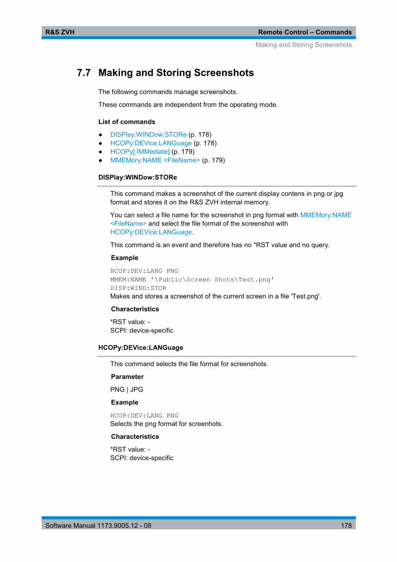
R&S ZVH Remote Control – Commands
Making and Storing Screenshots
Software Manual 1173.9005.12 - 08 178
7.7 Making and Storing Screenshots
The following commands manage screenshots.
These commands are independent from the operating mode.
List of commands
● DISPlay:WINDow:STORe (p. 178) ● HCOPy:DEVice:LANGuage (p. 178) ● HCOPy[:IMMediate] (p. 179) ● MMEMory:NAME <FileName> (p. 179)
DISPlay:WINDow:STORe
This command makes a screenshot of the current display contens in png or jpg format and stores it on the R&S ZVH internal memory.
You can select a file name for the screenshot in png format with MMEMory:NAME <FileName> and select the file format of the screenshot with HCOPy:DEVice:LANGuage.
This command is an event and therefore has no *RST value and no query.
Example
HCOP:DEV:LANG PNG MMEM:NAME '\Public\Screen Shots\Test.png' DISP:WIND:STOR Makes and stores a screenshot of the current screen in a file 'Test.png'.
Characteristics
*RST value: - SCPI: device-specific
HCOPy:DEVice:LANGuage
This command selects the file format for screenshots.
Parameter
PNG | JPG
Example
HCOP:DEV:LANG PNG Selects the png format for screenhots.
Characteristics
*RST value: - SCPI: device-specific

R&S ZVH Remote Control – Commands
Making and Storing Screenshots
Software Manual 1173.9005.12 - 08 179
HCOPy[:IMMediate]
This command makes a screenshot of the current display contens in png format and stores it on the R&S ZVH internal memory.
You can select a file name for the screenshot in png format with MMEMory:NAME <FileName> and select the file format of the screenshot with HCOPy:DEVice:LANGuage.
To make a screenshot in jpg format, use DISPlay:WINDow:STORe.
This command is an event and therefore has no *RST value and no query.
Example
HCOP:DEV:LANG PNG MMEM:NAME '\Public\Screen Shots\Test.png' HCOP Makes and stores a screenshot of the current screen in a file 'Test.png'.
Characteristics
*RST value: - SCPI: device-specific
MMEMory:NAME <FileName>
This command defines the path and file name that the R&S FSH uses for storing screenshots (see HCOPy[:IMMediate]). The path and file name comply with DOS conventions.
This command is an event and therefore has no *RST value and no query.
Parameter
<FileName> String containing the file name.
Example
MMEM:NAME 'Public\Screeshots\Test.png' Stores the screenshot on the in the corresponding directory on the R&S ZVH.
Characteristics
*RST value: - SCPI: device-specific
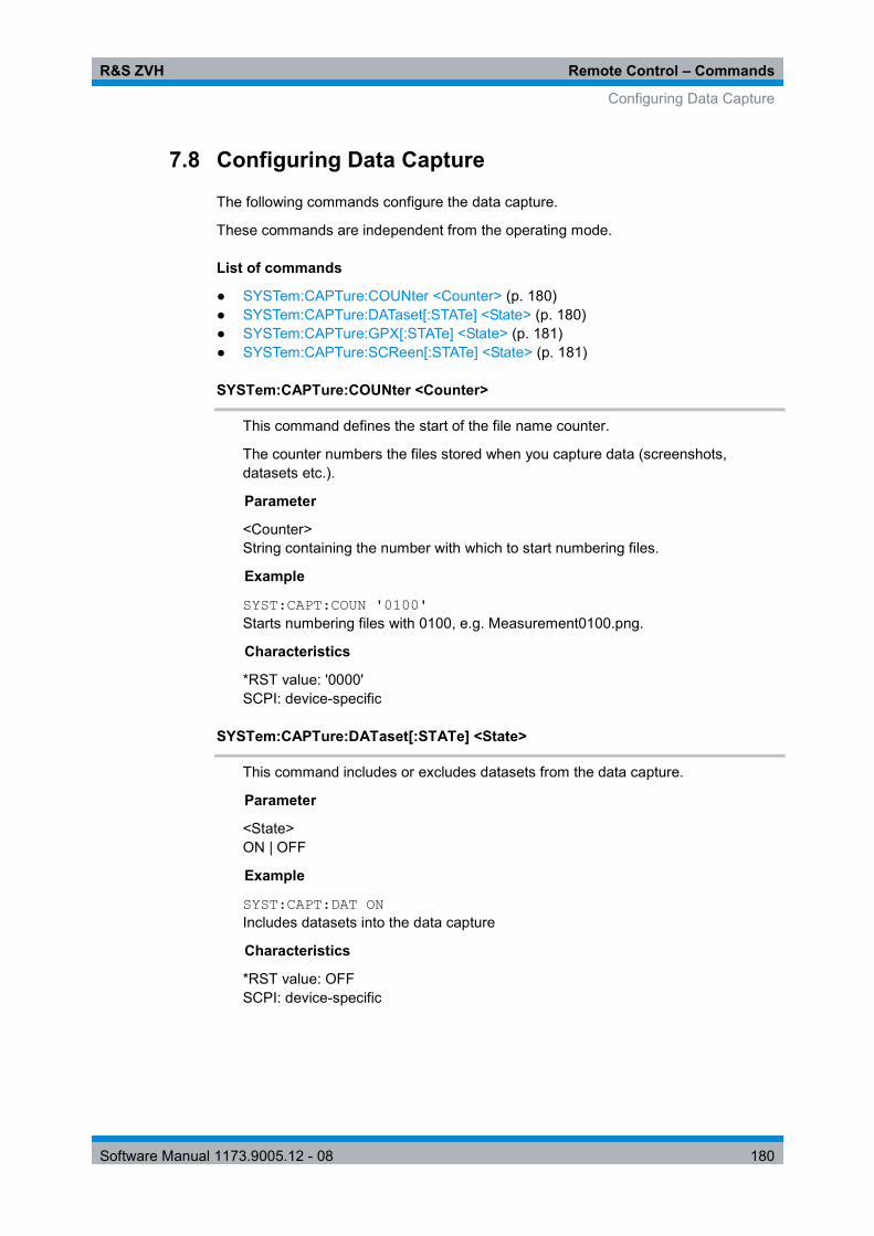
R&S ZVH Remote Control – Commands
Configuring Data Capture
Software Manual 1173.9005.12 - 08 180
7.8 Configuring Data Capture
The following commands configure the data capture.
These commands are independent from the operating mode.
List of commands
● SYSTem:CAPTure:COUNter <Counter> (p. 180) ● SYSTem:CAPTure:DATaset[:STATe] <State> (p. 180) ● SYSTem:CAPTure:GPX[:STATe] <State> (p. 181) ● SYSTem:CAPTure:SCReen[:STATe] <State> (p. 181)
SYSTem:CAPTure:COUNter <Counter>
This command defines the start of the file name counter.
The counter numbers the files stored when you capture data (screenshots, datasets etc.).
Parameter
<Counter> String containing the number with which to start numbering files.
Example
SYST:CAPT:COUN '0100' Starts numbering files with 0100, e.g. Measurement0100.png.
Characteristics
*RST value: '0000' SCPI: device-specific
SYSTem:CAPTure:DATaset[:STATe] <State>
This command includes or excludes datasets from the data capture.
Parameter
<State> ON | OFF
Example
SYST:CAPT:DAT ON Includes datasets into the data capture
Characteristics
*RST value: OFF SCPI: device-specific

R&S ZVH Remote Control – Commands
Configuring Data Capture
Software Manual 1173.9005.12 - 08 181
SYSTem:CAPTure:GPX[:STATe] <State>
This command includes or excludes GPX information from the data capture.
Parameter
<State> ON | OFF
Example
SYST:CAPT:GPX ON Includes GPX information into the data capture
Characteristics
*RST value: OFF SCPI: device-specific
SYSTem:CAPTure:SCReen[:STATe] <State>
This command includes or excludes screenahots from the data capture.
Parameter
<State> ON | OFF
Example
SYST:CAPT:SCR ON Includes screenshots into the data capture
Characteristics
*RST value: ON SCPI: device-specific

R&S ZVH Remote Control – Commands
Saving Events
Software Manual 1173.9005.12 - 08 182
7.9 Saving Events
The following commands configure the circumstances under which the R&S ZVH saves events.
These commands are independent from the operating mode.
Using the commands requires an GPS receiver and a storage device (SD card or memory stick).
List of commands
● SYSTem:SOEVent:DISTance:INTerval <Distance> (p. 182) ● SYSTem:SOEVent:LIMits:MODE <Mode> (p. 182) ● SYSTem:SOEVent:RECording:STORage <Device> (p. 183) ● SYSTem:SOEVent:SOURce <EventType> (p. 183) ● SYSTem:SOEVent:TIME:INTerval <Time> (p. 184) ● SYSTem:SOEVent:[:STATe] <State> (p. 184)
SYSTem:SOEVent:DISTance:INTerval <Distance>
This command defines a distance that you must cover before the R&S ZVH saves another coordinate.
Parameter
<Distance> Distance between one coordinate and the next.
Example
SYST:SOEV ON Turns on saving coordinates on an event.
SYST:SOEV:REC:STOR USB Selects an USB device as the storage device.
SYST:SOEV:SOUR DIST SYST:SOEV:DIST:INT 5 Saves the coordinates every 5 m.
Characteristics
*RST value: 1 m SCPI: device-specific
SYSTem:SOEVent:LIMits:MODE <Mode>
This command selects the limit check condition that must occur in order to save a coordinate.
Parameter
<Mode>

R&S ZVH Remote Control – Commands
Saving Events
Software Manual 1173.9005.12 - 08 183
FAILonly Saves only sweeps that contain a limit check violation.
STARtonfail Starts to save all sweeps from the moment a limit check fails.
STOPonfail Saves all sweeps until a limit check fails.
Example
SYST:SOEV:SOUR LIM SYST:SOEV:LIM:MODE FAIL Saves all sweeps that contain a violation of a limit check.
Characteristics
*RST value: STAR SCPI: device-specific
SYSTem:SOEVent:RECording:STORage <Device>
This command selects the storage device to save the coordinates to.
Parameter
<Device>
SDCard Saves coordinates to an SD card.
USB Saves coordinates to an USB device.
Example
See SYSTem:SOEVent:DISTance:INTerval <Distance>.
Characteristics
*RST value: SDCard SCPI: device-specific
SYSTem:SOEVent:SOURce <EventType>
This command selects the type of event that triggers saving the coordinates of your current location.
Parameter
<EventType>
ALLSweeps Saves coordinates after each sweep.
DISTanceint Saves coordinates after a certain distance has been covered.
LIMitsfail Saves coordinates when a limit check has failed.
TIMeinterval Saves coordinates after a certain length of time has passed.
Example
See SYSTem:SOEVent:DISTance:INTerval <Distance>.

R&S ZVH Remote Control – Commands
Saving Events
Software Manual 1173.9005.12 - 08 184
Characteristics
*RST value: TIMeinterval SCPI: device-specific
SYSTem:SOEVent:TIME:INTerval <Time>
This command defines a time interval that must pass before the R&S ZVH saves another coordinate.
Parameter
<Time> Time that must pass between one coordinate and the next.
Example
SYST:SOEV ON Turns on saving coordinates on an event.
SYST:SOEV:REC:STOR USB Selects an USB device as the storage device.
SYST:SOEV:SOUR TIM SYST:SOEV:TIME:INT 5 Saves the coordinates every 5 seconds.
Characteristics
*RST value: 1 s SCPI: device-specific
SYSTem:SOEVent:[:STATe] <State>
This command turns saving of your current coordinates in case of certain events on and off.
Parameter
<State> ON | OFF
Example
See SYSTem:SOEVent:DISTance:INTerval <Distance>.
Characteristics
*RST value: OFF SCPI: device-specific

R&S ZVH Remote Control – Commands
Configuring the Instrument
Software Manual 1173.9005.12 - 08 185
7.10 Configuring the Instrument
The following commands configure general instrument settings.
These commands are independent from the operating mode.
Contents
Mode Selection on page 185 Controlling the GPS Receiver on page 187 Display Configuration on page 191 Audio Settings on page 193 Setting up a Network Connection on page 195 System Settings on page 197
7.10.1 Mode Selection
This chapter describes all commands that select the operating mode of the R&S ZVH.
List of commands
● INSTrument[:SELect] <OperatingMode> (p. 185) ● INSTrument:NSELect <OperatingMode> (p. 186)
INSTrument[:SELect] <OperatingMode>
This command selects the operating mode.
Parameter
<OperatingMode>
ACT cable and antenna analyzer
NAN network analyzer
PM power meter
SANalyzer spectrum analyzer
VVMeter vector voltmeter
Example
INST SAN Selects spectrum analyzer mode.
Characteristics
*RST value: ACT SCPI: conform

R&S ZVH Remote Control – Commands
Configuring the Instrument
Software Manual 1173.9005.12 - 08 186
INSTrument:NSELect <OperatingMode>
This command selects the operating mode.
Parameter
1 spectrum analyzer
2 network analyzer
5 power meter
11 Cable and antenna analyzer
12 vector voltmeter
Example
INST:NSEL 1 Selects spectrum analyzer mode.
Characteristics
*RST value: 11 SCPI: conform
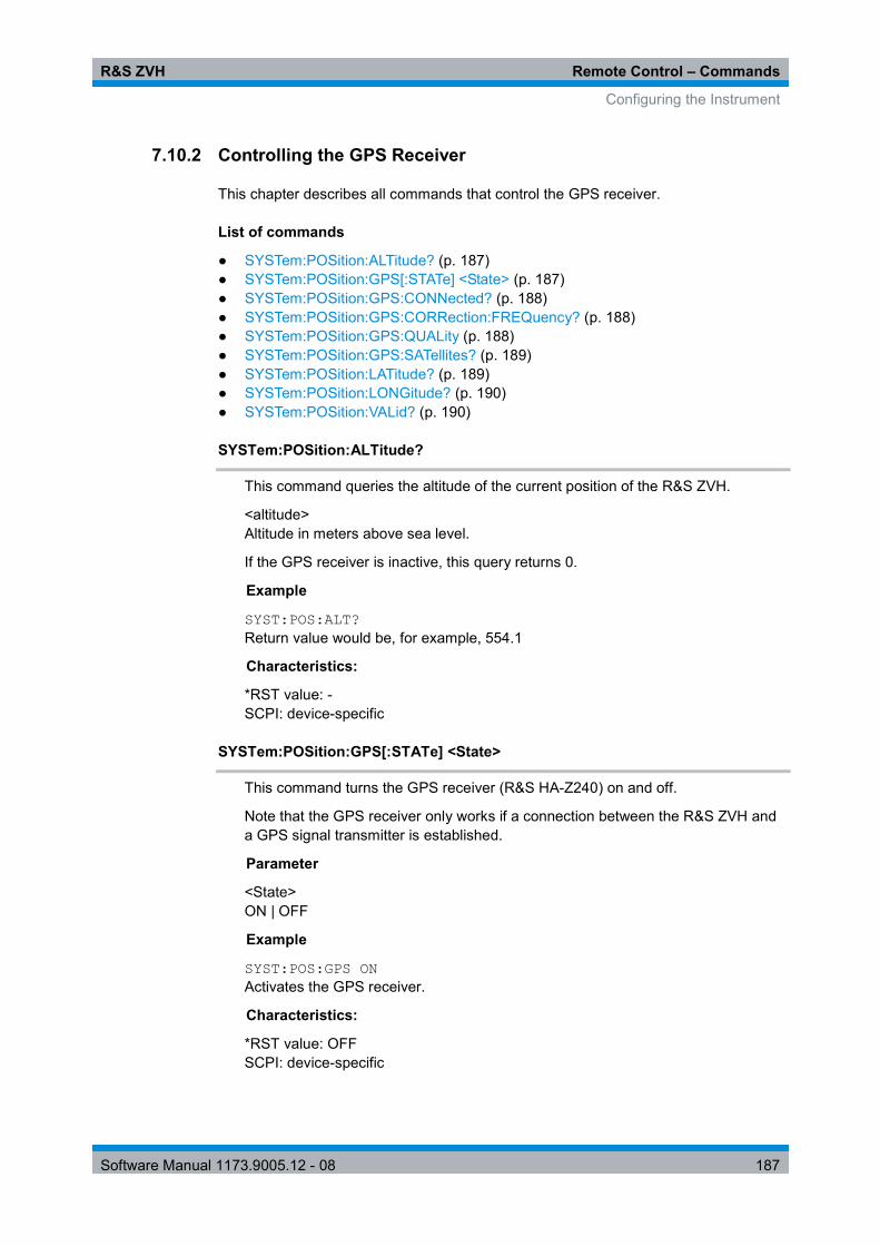
R&S ZVH Remote Control – Commands
Configuring the Instrument
Software Manual 1173.9005.12 - 08 187
7.10.2 Controlling the GPS Receiver
This chapter describes all commands that control the GPS receiver.
List of commands
● SYSTem:POSition:ALTitude? (p. 187) ● SYSTem:POSition:GPS[:STATe] <State> (p. 187) ● SYSTem:POSition:GPS:CONNected? (p. 188) ● SYSTem:POSition:GPS:CORRection:FREQuency? (p. 188) ● SYSTem:POSition:GPS:QUALity (p. 188) ● SYSTem:POSition:GPS:SATellites? (p. 189) ● SYSTem:POSition:LATitude? (p. 189) ● SYSTem:POSition:LONGitude? (p. 190) ● SYSTem:POSition:VALid? (p. 190)
SYSTem:POSition:ALTitude?
This command queries the altitude of the current position of the R&S ZVH.
<altitude> Altitude in meters above sea level.
If the GPS receiver is inactive, this query returns 0.
Example
SYST:POS:ALT? Return value would be, for example, 554.1
Characteristics:
*RST value: - SCPI: device-specific
SYSTem:POSition:GPS[:STATe] <State>
This command turns the GPS receiver (R&S HA-Z240) on and off.
Note that the GPS receiver only works if a connection between the R&S ZVH and a GPS signal transmitter is established.
Parameter
<State> ON | OFF
Example
SYST:POS:GPS ON Activates the GPS receiver.
Characteristics:
*RST value: OFF SCPI: device-specific

R&S ZVH Remote Control – Commands
Configuring the Instrument
Software Manual 1173.9005.12 - 08 188
SYSTem:POSition:GPS:CONNected?
This command queries if the R&S ZVH is currently connected to the GPS receiver.
Return values
0 No connection to a satellite.
1 Connection to a satellite established.
Example
SYST:POS:GPS:CONN? Characteristics:
*RST value: - SCPI: device-specific
SYSTem:POSition:GPS:CORRection:FREQuency?
This command queries the frequency correction factor.
The R&S ZVH calculates this factor from a reference signal provided by the GPS receiver R&S HA-Z240. The reference signal is used to determine the deviation of the internal clock of the instrument. The deviation can be turned into a correction factor for the measured frequency.
Return values
<floating point value>
If the GPS receiver is inactive, this query returns 0.
Example
SYST:POS:GPS:CORR:FREQ? Queries the frequency correction factor.
Characteristics:
*RST value: - SCPI: device-specific
SYSTem:POSition:GPS:QUALity?
This command queries the quality of the GPS signal.
Return values
INSufficient | LOW | MEDium | HIGh | EXCellent
Example
SYST:POS:GPS:QUAL? Characteristics:
*RST value: - SCPI: device-specific

R&S ZVH Remote Control – Commands
Configuring the Instrument
Software Manual 1173.9005.12 - 08 189
SYSTem:POSition:GPS:SATellites?
This command queries the number of tracked satellites.
Return values
<number of satellites>
Example
SYST:POS:GPS:SAT? Characteristics:
*RST value: - SCPI: device-specific
SYSTem:POSition:LATitude?
This command queries the latitude of the current position of the R&S ZVH.
Return values
<sign><degrees>,<minutes>,<seconds>
<sign> No sign = northern hemisphere Negative sign (-) = southern hemisphere
<degrees> Degrees of latitude (integer value)
<minutes> Minutes of latitude (integer value)
<seconds> Seconds of latitude (floating point value)
Example
SYST:POS:LAT? Return value would be, for example, 48,7,40.0 for 48°, 7 ', 40.0" in the northern hemisphere.
Characteristics:
*RST value: - SCPI: device-specific

R&S ZVH Remote Control – Commands
Configuring the Instrument
Software Manual 1173.9005.12 - 08 190
SYSTem:POSition:LONGitude?
This command queries the longitude of the current position of the R&S ZVH.
Return values
<sign><degrees>,<minutes>,<seconds>
<sign> No sign = east Negative sign (-) = west
<degrees> Degrees of longitude (integer value)
<minutes> Minutes of longitude (integer value)
<seconds> Seconds of longitude (floating point number)
Example
SYST:POS:LONG? Return value would be, for example, 11,36,46.2 for 11°, 36', 46.2" East
Characteristics:
*RST value: - SCPI: device-specific
SYSTem:POSition:VALid?
This command queries if the current position is valid.
Return values
0 GPS position is not valid.
1 GPS position is valid.
Example
SYST:POS:VAL? Characteristics:
*RST value: -
SCPI: device-specific

R&S ZVH Remote Control – Commands
Configuring the Instrument
Software Manual 1173.9005.12 - 08 191
7.10.3 Display Configuration
This chapter describes commands to set up the display of the R&S ZVH via remote control.
List of Commands
● DISPlay:BRIGhtness <Brightness> (p. 191) ● DISPlay:CMAP <ColorScheme> (p. 191) ● DISPlay:CMAP:DEFault (p. 192) ● DISPlay:DATE:FORMat <DateFormat> (p. 192)
DISPlay:BRIGhtness <Brightness>
This command sets the brightness of the display backlight.
Parameter
<Brightness> Numeric value in the range from 0 to 1
Example
DISP:BRIG 0.80 Sets the brightness of the display to 80%
Characteristics
*RST value: 0.5 (50%) SCPI: device-specific
DISPlay:CMAP <ColorScheme>
This command sets the color scheme of the display.
Parameter
<ColorScheme>
COLor Color.
BW Black & white.
PF Printer friendly.
Example
DISP:CMAP BW Sets the screen colors to black and white
Characteristics
*RST value: COLor SCPI: conform

R&S ZVH Remote Control – Commands
Configuring the Instrument
Software Manual 1173.9005.12 - 08 192
DISPlay:CMAP:DEFault
This command sets the display to the default state.
This command is an event and therefore has no query and no *RST value.
Example
DISP:CMPA:DEF Restores the original color scheme
Characteristics
*RST value: - SCPI: conform
DISPlay:DATE:FORMat <DateFormat>
This command sets the display date format.
Parameter
<DateFormat> DDMMyyyy | MMDDyyyy
Example
DISP:DATE:FORM DDMMyyyy Characteristics
*RST value: DDMMyyyy SCPI: device-specific

R&S ZVH Remote Control – Commands
Configuring the Instrument
Software Manual 1173.9005.12 - 08 193
7.10.4 Audio Settings
This chapter describes all commands to control the audio functions of the R&S ZVH.
List of commands
● SYSTem:AUDio:VOLume <Volume> (p. 193) ● SYSTem:BEEPer:VOLume <Volume> (p. 193) ● SYSTem:BEEPer:KEY:VOLume <Volume> (p. 193)
SYSTem:AUDio:VOLume <Volume>
This command sets the volume of the internal speaker.
Parameter
<Volume> Numeric value in the range from 0 to 1
Example
SYST:AUD:VOL 0.40 Sets the volume to 40%
Characteristics
*RST value: 0.3 (30%) SCPI: device-specific
SYSTem:BEEPer:VOLume <Volume>
This command sets the volume of the system beeper.
Parameter
<Volume> Numeric value in the range from 0 to 1
Example
SYST:BEEP:VOL 0.50 Sets the volume of the beeper to 50%
Characteristics
*RST value: 0.6 (60%) SCPI: conform
SYSTem:BEEPer:KEY:VOLume <Volume>
This command sets the volume of the keyboard click noise.
Parameter
<Volume> Numeric value in the range from 0 to 1

R&S ZVH Remote Control – Commands
Configuring the Instrument
Software Manual 1173.9005.12 - 08 194
Example
SYST:BEEP:KEY:VOL 0.10 Sets of keyboard clicking volume to 10%
Characteristics
*RST value: 0.3 (30%) SCPI: conform

R&S ZVH Remote Control – Commands
Configuring the Instrument
Software Manual 1173.9005.12 - 08 195
7.10.5 Setting up a Network Connection
This chapter describes all commands that are used if the R&S ZVH is part of a network.
List of commands
● SYSTem:COMMunicate:LAN:ETHernet? (p. 195) ● SYSTem:COMMunicate:LAN:GATeway <Gateway> (p. 195) ● SYSTem:COMMunicate:LAN:SUBMask <SubnetMask> (p. 195) ● SYSTem:COMMunicate:SOCKet:ADDRess <IPAddress> (p. 196) ● SYSTem:COMMunicate:SOCKet:DHCP[:STATe] <State> (p. 196) ● SYSTem:COMMunicate:SOCKet:PORT <Port> (p. 196)
SYSTem:COMMunicate:LAN:ETHernet?
This command queries the MAC address of the R&S ZVH.
This command is a query and therefore has no *RST value.
Example
SYST:COMM:LAN:ETH? Returns the MAC address
Characteristics
*RST value: - SCPI: device-specific
SYSTem:COMMunicate:LAN:GATeway <Gateway>
This command sets the gateway in the LAN.
Parameter
<Gateway> String containing the identifier of the gateway.
Characteristics
*RST value: - SCPI: device-specific
SYSTem:COMMunicate:LAN:SUBMask <SubnetMask>
This command sets the subnet mask of the R&S ZVH.
Parameter
<SubnetMask> String containing the subnet mask ('x.x.x.x').
Example
SYST:COMM:LAN:SUBM '255.255.255.0' Sets the subnet mask address to 255.255.255.0

R&S ZVH Remote Control – Commands
Configuring the Instrument
Software Manual 1173.9005.12 - 08 196
Characteristics
*RST value: 255.255.255.0 SCPI: device-specific
SYSTem:COMMunicate:SOCKet:ADDRess <IPAddress>
This command sets the IP address of the R&S ZVH.
Parameter <IPAddress> String containing the IP address ('x.x.x.x').
Example
SYST:COMM:SOCK:ADDR '172.76.68.30' Sets the IP address of the R&S ZVH to 172.76.68.30
Characteristics
*RST value: 172.76.68.24 SCPI: device-specific
SYSTem:COMMunicate:SOCKet:DHCP[:STATe] <State>
This command turns the Dynamic Host Configuration Protocol (DHCP) on and off.
Parameter
<State> ON | OFF
Example
SYST:COMM:SOCK:DHCP ON Activates DHCP.
Characteristics
*RST value: ON SCPI: device-specific
SYSTem:COMMunicate:SOCKet:PORT <Port>
This command sets the port number for the connection.
Parameter
<Port> Port number
Example
SYST:COMM:SOCK:PORT 1000 Sets the port number to 1000
Characteristics
*RST value: 5555 SCPI: device-specific
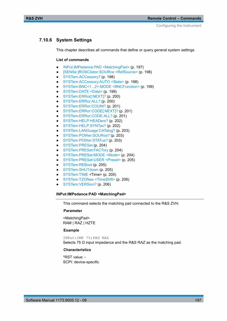
R&S ZVH Remote Control – Commands
Configuring the Instrument
Software Manual 1173.9005.12 - 08 197
7.10.6 System Settings
This chapter describes all commands that define or query general system settings.
List of commands
● INPut:IMPedance:PAD <MatchingPad> (p. 197) ● [SENSe:]ROSCilator:SOURce <RefSource> (p. 198) ● SYSTem:ACCessory? (p. 198) ● SYSTem:ACCessory:AUTO <State> (p. 198) ● SYSTem:BNC<1...2>:MODE <BNCFunction> (p. 199) ● SYSTem:DATE <Date> (p. 199) ● SYSTem:ERRor[:NEXT]? (p. 200) ● SYSTem:ERRor:ALL? (p. 200) ● SYSTem:ERRor:COUNt? (p. 201) ● SYSTem:ERRor:CODE[:NEXT]? (p. 201) ● SYSTem:ERRor:CODE:ALL? (p. 201) ● SYSTem:HELP:HEADers? (p. 202) ● SYSTem:HELP:SYNTax? (p. 202) ● SYSTem:LANGuage:CATalog? (p. 203) ● SYSTem:POWer:SOURce? (p. 203) ● SYSTem:POWer:STATus? (p. 203) ● SYSTem:PRESet (p. 204) ● SYSTem:PRESet:FACTory (p. 204) ● SYSTem:PRESet:MODE <Mode> (p. 204) ● SYSTem:PRESet:USER <Preset> (p. 205) ● SYSTem:REBoot (p. 205) ● SYSTem:SHUTdown (p. 205) ● SYSTem:TIME <Time> (p. 205) ● SYSTem:TZONee <TimeShift> (p. 206) ● SYSTem:VERSion? (p. 206)
INPut:IMPedance:PAD <MatchingPad>
This command selects the matching pad connected to the R&S ZVH.
Parameter
<MatchingPad> RAM | RAZ | HZTE
Example
INPut:IMP 75;PAD RAZ Selects 75 Ω input impedance and the R&S RAZ as the matching pad.
Characteristics
*RST value: - SCPI: device-specific

R&S ZVH Remote Control – Commands
Configuring the Instrument
Software Manual 1173.9005.12 - 08 198
[SENSe:]ROSCilator:SOURce <RefSource>
This command selects the source of the frequency reference oscillator.
If you use an external reference signal, make sure to connect the signal to the Ext Ref BNC connector of the R&S ZVH.
Parameter
<RefSource>
INTernal Internal reference.
EXTernal External reference.
Example
ROSC:SOUR EXT Activates external source as reference signal.
Characteristics
*RST value: - SCPI: device-specific
SYSTem:ACCessory?
This command queries the type of measurement accessory, if one is connected to the R&S ZVH (for example an isotropic antenna or power sensor).
Return value
Name of the accessory.
Example
SYST:ACC? Queries connected measurement accessories.
Characteristics
*RST value: - SCPI: device-specific
SYSTem:ACCessory:AUTO <State>
This command turns automatic detection of connected measurement accessories on and off.
Parameter
<State> ON | OFF
Example
SYST:ACC:AUTO ON Turns on automatic accessory detection.

R&S ZVH Remote Control – Commands
Configuring the Instrument
Software Manual 1173.9005.12 - 08 199
Characteristics
*RST value: - SCPI: device-specific
SYSTem:BNC<1...2>:MODE <BNCFunction>
This command configures the BNC sockets.
The numeric suffix at BNC selects the BNC socket you want to configure.
Parameter
<BNCFunction>
REFerence Input for external reference signal (BNC 1)
TRIGger Input for external trigger (BNC 1)
BIAS BIAS port (BNC1 and BNC 2)
IF3 IF output (BNC 2)
INTernalbias Internal DC BIAS (BNC 2)
Example
SYST:BNC2:MODE TRIG Sets the seconds BNC socket to trigger input.
Characteristics
*RST value: BNC 1: TRIGger, BNC 2: IF3 SCPI: device-specific
SYSTem:DATE <Date>
This command sets the date for the internal calendar.
Parameter
<Date> Numeric value indicating the date
You have to enter the date as comma separated values after the string with the file name. The sequence is year,month,day.
The available value range is 1980...2099, 1...12, 1...31
Example
SYST:DATE 2000,6,1 Sets the date to 1/6/2000
Characteristics
*RST value: - SCPI: conform

R&S ZVH Remote Control – Commands
Configuring the Instrument
Software Manual 1173.9005.12 - 08 200
SYSTem:ERRor[:NEXT]?
This command queries the oldest entry in the error queue and deletes it.
This command is a query and therefore has no *RST value.
Return value
<error number>,<error description>
<error number> Number that contains information about the error.
Negative number: error as defined in the SCPI standard. Positive number: error that is specific to the R&S ZVH.
<error description> String containing a short error description.
If the error queue is empty, the command returns 0,'no error'.
Example
STAT:ERR? Characteristics
*RST value: - SCPI: conform
SYSTem:ERRor:ALL?
This command queries the complete error queue.
This command is a query and therefore no *RST value.
Return value
<error number>,<error description>
<error number> Number that contains information about the error.
Negative number: error as defined in the SCPI standard. Positive number: error that is specific to the R&S ZVH.
<error description> String containing a short error description.
The number of values depends on the length of the queue.
If the error queue is empty, the command returns 0,'no error'.
Example
SYST:ERR:ALL? Characteristics
*RST value: - SCPI: device-specific

R&S ZVH Remote Control – Commands
Configuring the Instrument
Software Manual 1173.9005.12 - 08 201
SYSTem:ERRor:CODE[:NEXT]?
This command queries the code of the next error in the error queue.
This command is a query and therefore has no *RST value.
Return value
<error number> number that contains information about the error
Negative number: error as defined in the SCPI standard Positive number: error that is specific to the R&S ZVH
If the error queue is empty, the command returns 0.
Example
STAT:ERR:CODE? Characteristics
*RST value: - SCPI: conform
SYSTem:ERRor:CODE:ALL?
This command queries the complete error queue.
This command is a query and therefore no *RST value.
Return value
<error number> number that contains information about the error
Negative number: error as defined in the SCPI standard Positive number: error that is specific to the R&S ZVH
The number of values depends on the length of the queue.
If the error queue is empty, the command returns 0,'no error'.
Example
SYST:ERR:CODE:ALL? Characteristics
*RST value: - SCPI: device-specific
SYSTem:ERRor:COUNt?
This command queries the number of errors currently in the error queue.
This command is a query and therefore no *RST value.
Return value
<numeric_value> number of the errors in the queue

R&S ZVH Remote Control – Commands
Configuring the Instrument
Software Manual 1173.9005.12 - 08 202
Example
SYST:ERR:COUN? Characteristics
*RST value: - SCPI: device-specific
SYSTem:HELP:HEADers?
This command returns a list of all available remote control commands.
This command is a query and therefore no *RST value.
Example
SYST:HELP:HEAD? Returns the syntax of all available commands.
Characteristics
*RST value: - SCPI: conform
SYSTem:HELP:SYNTax?
This command returns the full syntax of the specified command.
This command is a query and therefore no *RST value.
Parameter
<Command> String containing the command you want to query
Example
SYST:HELP:SYNT? 'SYST:ERR?' Returns the full syntax. In this case: 'SYSTem:ERRor[:NEXT]'.
Characteristics
*RST value: - SCPI: device-specific
SYSTem:LANGuage <Language>
This command sets the language of the R&S ZVH user interface. You can query a list of available languages with SYSTem:LANGuage:CATalog?.
Parameter
<Language> string containing the language
Example
SYST:LANG 'english' Sets the system language to English

R&S ZVH Remote Control – Commands
Configuring the Instrument
Software Manual 1173.9005.12 - 08 203
Characteristics
*RST value: - SCPI: conform
SYSTem:LANGuage:CATalog?
This command lists all languages available for the user interface.
This command is a query and therefore no *RST value.
Example
SYST:LANG:CAT? Characteristics
*RST value: - SCPI: device-specific
SYSTem:POWer:SOURce?
This command queries the current R&S ZVH power source.
This command is a query and therefore has no *RST value.
Return values
ADAP R&S ZVH is powered by the AC power supply.
BATT R&S ZVH is powered by the battery.
Example
SYST:POW:SOUR? Characteristics
*RST value: - SCPI: conform
SYSTem:POWer:STATus?
This command queries the remaining power of the battery.
This command is a query and therefore has no *RST value.
Return values
Numeric value in the range from 0 to 100 %.
Example
SYST:POW:STAT? Characteristics
*RST value: - SCPI: conform

R&S ZVH Remote Control – Commands
Configuring the Instrument
Software Manual 1173.9005.12 - 08 204
SYSTem:PRESet
Resets the R&S ZVH to its default state or a state defined by the user, depending on SYSTem:PRESet:MODE.
This command is an event and therefore has no *RST value and no query.
Example
SYST:PRES Characteristics
*RST value: - SCPI: conform
SYSTem:PRESet:FACTory
This command initiates an instrument reset back to factory settings.
This command is an event and therefore has no query and no *RST value.
Example
SYST:PRES:FACT Resets the R&S ZVH to its factory settings.
Characteristics
*RST value: - SCPI: device-specific
SYSTem:PRESet:MODE <Mode>
This command selects the preset mode.
Parameter
<Mode>
DEFault Default preset state.
USER User defined preset state.
Example
SYST:PRES:MODE USER Selects a user defined preset.
Characteristics
*RST value: - SCPI: conform

R&S ZVH Remote Control – Commands
Configuring the Instrument
Software Manual 1173.9005.12 - 08 205
SYSTem:PRESet:USER <Preset>
This command selects a file containing a user defined preset state.
Parameter
<Preset> filename of the user defined preset state
Characteristics
*RST value: - SCPI: conform
SYSTem:REBoot
This command initiates a reboot of the R&S ZVH.
This command is an event and therefore has no *RST value and no query.
Example
SYST:REB Restarts the R&S ZVH.
Characteristics
*RST value: - SCPI: conform
SYSTem:SHUTdown
This command turns the R&S ZVH off.
This command is an event and therefore has no *RST value and no query.
Example
SYST:SHUT Turns the R&S ZVH off.
Characteristics
*RST value: - SCPI: conform
SYSTem:TIME <Time>
This command sets the internal clock.
Parameter
<Time> Numeric value indicating the time
You have to enter the time as comma separated values after the string with the file name. The sequence is hour,minute,second.
The available value range is 0...23, 0...59, 0...59.
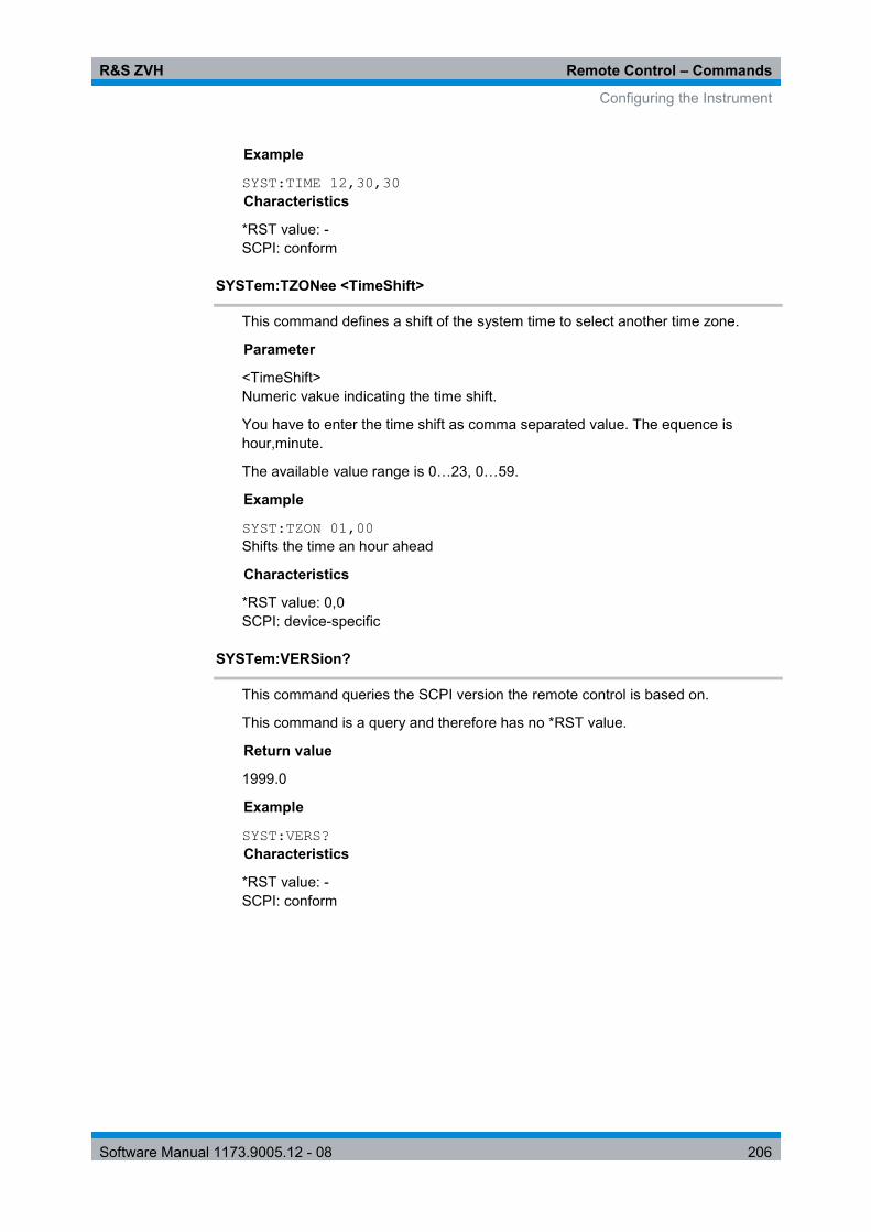
R&S ZVH Remote Control – Commands
Configuring the Instrument
Software Manual 1173.9005.12 - 08 206
Example
SYST:TIME 12,30,30 Characteristics
*RST value: - SCPI: conform
SYSTem:TZONee <TimeShift>
This command defines a shift of the system time to select another time zone.
Parameter
<TimeShift> Numeric vakue indicating the time shift.
You have to enter the time shift as comma separated value. The equence is hour,minute.
The available value range is 0…23, 0…59.
Example
SYST:TZON 01,00 Shifts the time an hour ahead
Characteristics
*RST value: 0,0 SCPI: device-specific
SYSTem:VERSion?
This command queries the SCPI version the remote control is based on.
This command is a query and therefore has no *RST value.
Return value
1999.0
Example
SYST:VERS? Characteristics
*RST value: - SCPI: conform

R&S ZVH Remote Control – Commands
Status Reporting System
Software Manual 1173.9005.12 - 08 207
7.11 Status Reporting System
The status reporting system stores all information on the present operating state of the instrument, and on errors which have occurred. This information is stored in the status registers and in the error queue. The status registers and the error queue can be queried via Ethernet.
The information is of a hierarchical structure. The register status byte (STB) defined in IEEE 488.2 and its associated mask register service request enable (SRE) form the uppermost level. The STB receives its information from the standard event status register (ESR) which is also defined in IEEE 488.2 with the associated mask register standard event status enable (ESE) and registers STATus:OPERation and STATus:QUEStionable which are defined by SCPI and contain detailed information on the instrument.
The output buffer contains the messages the instrument returns to the controller. It is not part of the status reporting system but determines the value of the MAV bit in the STB.
7.11.1 Structure of an SCPI Status Register
Each standard SCPI register consists of 5 parts which each have a width of 16 bits and have different functions. The individual bits are independent of each other, i.e. each hardware status is assigned a bit number that applies to all five parts. For example, bit 0 of the STATus:OPERation register is assigned to the calibration status of the R&S ZVH. Bit 15 (the most significant bit) is set to zero for all parts. Thus the contents of the register parts can be processed by the controller as positive integer.
15 121314 CONDition Part 0123
15 121314 NTRansition Part 0123
15 121314 PTRansition Part 0123
15 121314 EVENt Part 0123
15 121314 ENABle Part 0123
& &&& & &&& & &&& & &&
to higher order register
+ Sum bit & = logical AND+ = logical ORof all bits
Figure 7-1: The status-register model
7.11.1.1 CONDition part
The CONDition part is directly written into by the hardware or the sum bit of the next lower register. Its contents reflects the current instrument status. This register part can only be read, but not written into or cleared. Its contents is not affected by reading.

R&S ZVH Remote Control – Commands
Status Reporting System
Software Manual 1173.9005.12 - 08 208
7.11.1.2 PTRansition part
The Positive-TRansition part acts as an edge detector. When a bit of the CONDition part is changed from 0 to 1, the associated PTR bit decides whether the EVENt bit is set to 1.
PTR bit =1: the EVENt bit is set.
PTR bit =0: the EVENt bit is not set.
This part can be written into and read at will. Its contents is not affected by reading.
7.11.1.3 NTRansition part
The Negative-TRansition part also acts as an edge detector. When a bit of the CONDition part is changed from 1 to 0, the associated NTR bit decides whether the EVENt bit is set to 1.
NTR-Bit = 1: the EVENt bit is set.
NTR-Bit = 0: the EVENt bit is not set.
This part can be written into and read at will. Its contents is not affected by reading.
With these two edge register parts the user can define which state transition of the condition part (none, 0 to 1, 1 to 0 or both) is stored in the EVENt part.
7.11.1.4 EVENt part
The EVENt part indicates whether an event has occurred since the last reading, it is the "memory" of the condition part. It only indicates events passed on by the edge filters. It is permanently updated by the instrument. This part can only be read by the user. Reading the register clears it. This part is often equated with the entire register.
7.11.1.5 ENABle part
The ENABle part determines whether the associated EVENt bit contributes to the sum bit (see below). Each bit of the EVENt part is ANDed with the associated ENABle bit (symbol '&'). The results of all logical operations of this part are passed on to the sum bit via an OR function (symbol '+').
ENABle-Bit = 0: the associated EVENt bit does not contribute to the sum bit
ENABle-Bit = 1: if the associated EVENT bit is "1", the sum bit is set to "1" as well.
This part can be written into and read by the user at will. Its contents is not affected by reading.

R&S ZVH Remote Control – Commands
Status Reporting System
Software Manual 1173.9005.12 - 08 209
7.11.1.6 Sum bit
As indicated above, the sum bit is obtained from the EVENt and ENABle part for each register. The result is then entered into a bit of the CONDition part of the higher-order register.
The instrument automatically generates the sum bit for each register. Thus an event, e.g. a PLL that has not locked, can lead to a service request throughout all levels of the hierarchy.
The service request enable register SRE defined in IEEE 488.2 can be taken as ENABle part of the STB if the STB is structured according to SCPI. By analogy, the ESE can be taken as the ENABle part of the ESR.
7.11.2 Overview of the Status Register
The following figure shows the status registers used by the R&S ZVH.
Figure 7-2: Overview of the status registers

R&S ZVH Remote Control – Commands
Status Reporting System
Software Manual 1173.9005.12 - 08 210
7.11.3 Status Byte (STB) & Service Request Enable Register (SRE)
The STB is already defined in IEEE 488.2. It provides a rough overview of the instrument status by collecting the pieces of information of the lower registers. It can thus be compared with the CONDition part of an SCPI register and assumes the highest level within the SCPI hierarchy. A special feature is that bit 6 acts as the sum bit of the remaining bits of the status byte.
The STATUS BYTE is read using the command "*STB?" or a serial poll.
The STB is linked to the SRE. The latter corresponds to the ENABle part of the SCPI registers in its function. Each bit of the STB is assigned a bit in the SRE. Bit 6 of the SRE is ignored. If a bit is set in the SRE and the associated bit in the STB changes from 0 to 1, a service request (SRQ) is generated, which triggers an interrupt in the controller if this is appropriately configured and can be further processed there. The SRE can be set using the command "*SRE" and read using the command "*SRE?"
Table 7-1: Meaning of the bits used in the Status Byte
Bit No. Meaning
0 to 1 Not used
2 Error Queue not empty The bit is set when an entry is made in the error queue. If this bit is enabled by the SRE, each entry of the error queue generates a service request. Thus an error can be recognized and specified in greater detail by polling the error queue. The poll provides an informative error message. This procedure is to be recommended since it considerably reduces the problems involved with remote control.
3 QUEStionable status sum bit The bit is set if an EVENt bit is set in the QUEStionable: status register and the associated ENABle bit is set to 1.
A set bit indicates a questionable instrument status, which can be specified in greater detail by polling the QUEStionable status register.
4 MAV bit (message available)
The bit is set if a message is available in the output buffer which can be read. This bit can be used to enable data to be automatically read from the instrument to the controller.
5 ESB bit Sum bit of the event status register. It is set if one of the bits in the event status register is set and enabled in the event status enable register. Setting of this bit indicates a serious error which can be specified in greater detail by polling the event status register.
6 MSS bit (master status summary bit)
The bit is set if the instrument triggers a service request. This is the case if one of the other bits of this registers is set together with its mask bit in the service request enable register SRE.
7 OPERation status register sum bit The bit is set if an EVENt bit is set in the OPERation status register and the associated ENABle bit is set to 1. A set bit indicates that the instrument is just performing an action. The type of action can be determined by polling the OPERation status register.
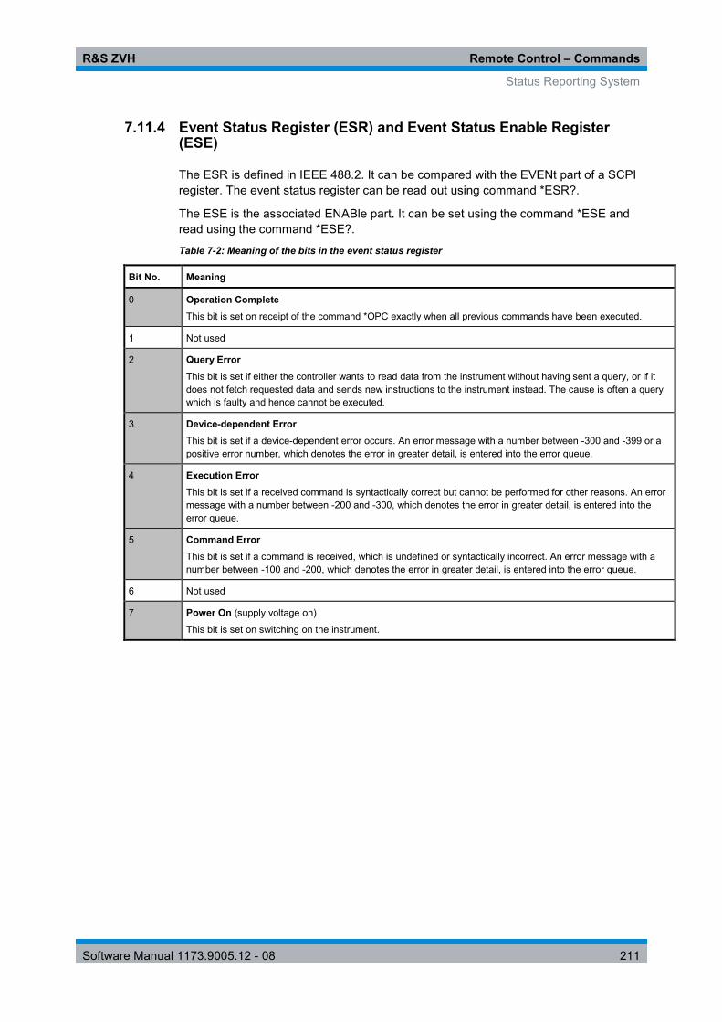
R&S ZVH Remote Control – Commands
Status Reporting System
Software Manual 1173.9005.12 - 08 211
7.11.4 Event Status Register (ESR) and Event Status Enable Register (ESE)
The ESR is defined in IEEE 488.2. It can be compared with the EVENt part of a SCPI register. The event status register can be read out using command *ESR?.
The ESE is the associated ENABle part. It can be set using the command *ESE and read using the command *ESE?.
Table 7-2: Meaning of the bits in the event status register
Bit No. Meaning
0 Operation Complete This bit is set on receipt of the command *OPC exactly when all previous commands have been executed.
1 Not used
2 Query Error This bit is set if either the controller wants to read data from the instrument without having sent a query, or if it does not fetch requested data and sends new instructions to the instrument instead. The cause is often a query which is faulty and hence cannot be executed.
3 Device-dependent Error This bit is set if a device-dependent error occurs. An error message with a number between -300 and -399 or a positive error number, which denotes the error in greater detail, is entered into the error queue.
4 Execution Error This bit is set if a received command is syntactically correct but cannot be performed for other reasons. An error message with a number between -200 and -300, which denotes the error in greater detail, is entered into the error queue.
5 Command Error This bit is set if a command is received, which is undefined or syntactically incorrect. An error message with a number between -100 and -200, which denotes the error in greater detail, is entered into the error queue.
6 Not used
7 Power On (supply voltage on)
This bit is set on switching on the instrument.

R&S ZVH Remote Control – Commands
Status Reporting System
Software Manual 1173.9005.12 - 08 212
7.11.4.1 STATus:OPERation Register
In the CONDition part, this register contains information on which actions the instrument is being executing or, in the EVENt part, information on which actions the instrument has executed since the last reading. It can be read using the commands STATus:OPERation:CONDition? or STATus:OPERation[:EVENt]?.
Table 7-3: Meaning of the bits in the STATus:OPERation register
Bit No. Meaning
0 CALibrating This bit is set as long as the instrument is performing a calibration.
1 to 14 Not used
15 This bit is always 0
7.11.4.2 STATus:QUEStionable Register
This register contains information about indefinite states which may occur if the unit is operated without meeting the specifications. It can be read using the commands STATus:QUEStionable: CONDition? and STATus:QUEStionable[:EVENt]?.
Table 7-4: Meaning of bits in STATus:QUEStionable register
Bit No. Meaning
0 to 1 These bits are not used
2 BATTERY LOW If the instrument is running without any external power supply and the charging level of the internal battery is approximately lower than 5% this bit is set to indcate that the system will be shut down automatically in approx. 5 minutes.
3 Not used
4 TEMPerature This bit is set if a questionable temperature occurs.
5 to 8 Not used
9 LIMit (device-specific) This bit is set if a limit value is violated
10 CALibration The bit is set if a measurement is performed unaligned (label UNCAL)
11 to 14 Not used
15 This bit is always 0.

R&S ZVH Remote Control – Commands
Status Reporting System
Software Manual 1173.9005.12 - 08 213
7.11.4.3 STATus:QUEStionable:FREQuency Register
This register contains information about the reference frequency. It can be read using the commands STATus:QUEStionable:LIMit:FREQuency? and STATus:QUEStionable:FREQuency[:EVENt]?.
Table 7-5: Meaning of bits in STATus:QUEStionable:FREQuency register
Bit No. Meaning
0 to 7 Not used
8 EXTernal REFerence This bit is set if an external reference is used.
9 to 14 Not used
15 This bit is always 0.
7.11.4.4 STATus:QUEStionable:LIMit Register
This register contains information about the observance of limit lines. It can be read using the commands STATus:QUEStionable:LIMit:CONDition? and STATus:QUEStionable:LIMit[:EVENt]?.
Table 7-6: Meaning of bits in STATus:QUEStionable:LIMit register
Bit No. Meaning
0 LIMit 1 FAIL This bit is set if limit line 1 is violated.
1 LIMit 2 FAIL This bit is set if limit line 2 is violated.
2 to 14 Not used
15 This bit is always 0.
7.11.4.5 STATus:QUEStionable:POWer Register
This register contains information about possible overload states. It can be read using the commands STATus:QUEStionable:POWer:CONDition? and STATus:QUEStionable:POWer[:EVENt]?.
Table 7-7: Meaning of bits in STATus:QUEStionable:POWer register
Bit No. Meaning
0 to 1 Not used
2 IF_Overload This bit is set if the IF path is overloaded. ’IFOVL’ is displayed.
3 to 14 Not used
15 This bit is always 0.

R&S ZVH Remote Control – Commands
Status Reporting System
Software Manual 1173.9005.12 - 08 214
7.11.5 Application of the Status Reporting Systems
In order to be able to effectively use the status reporting system, the information contained there must be transmitted to the controller and further processed there. There are several methods which are represented in the following.
7.11.5.1 Service Request
Under certain circumstances, the instrument can send a service request (SRQ) to the controller. Usually this service request initiates an interrupt at the controller, to which the control program can react appropriately. As evident from Fig. 1-4, an SRQ is always initiated if one or several of bits 2, 3, 4, 5 or 7 of the status byte are set and enabled in the SRE. Each of these bits combines the information of a further register, the error queue or the output buffer. The ENABle parts of the status registers can be set so that arbitrary bits in an arbitrary status register initiate an SRQ. In order to make use of the possibilities of the service request effectively, all bits should be set to "1" in enable registers SRE and ESE.
Example
Use of the command *OPC to generate an SRQ at the end of a sweep
CALL InstrWrite(analyzer, "*ESE 1") 'Set bit 0 in the ESE (Operation Complete)
CALL InstrWrite(analyzer, "*SRE 32") 'Set bit 5 in the SRE (ESB)?
After its settings have been completed, the instrument generates an SRQ.
The SRQ is the only possibility for the instrument to become active on its own. Each controller program should set the instrument in a way that a service request is initiated in the case of malfunction. The program should react appropriately to the service request.
7.11.5.2 Serial Poll
In a serial poll, just as with command *STB, the status byte of an instrument is queried. However, the query is realized via interface messages and is thus clearly faster. The serial-poll method has already been defined in IEEE 488.1 and used to be the only standard possibility for different instruments to poll the status byte. The method also works with instruments which do not adhere to SCPI or IEEE 488.2.
The VISUAL BASIC command for executing a serial poll is IBRSP(). Serial poll is mainly used to obtain a fast overview of the state of several instruments connected to the controller.

R&S ZVH Remote Control – Commands
Status Reporting System
Software Manual 1173.9005.12 - 08 215
7.11.5.3 Query by Means of Commands
Each part of any status register can be read by means of queries. The individual commands are listed in the description of the STATus Subsystem. The returned value is always a number that represents the bit pattern of the queried register. This number is evaluated by the controller program.
Queries are usually used after an SRQ in order to obtain more detailed information on the cause of the SRQ.
7.11.5.4 Error Queue Query
Each error state in the instrument leads to an entry in the error queue. The entries of the error queue are detailed plain-text error messages that can be displayed via manual operation using the setup menu or queried via remote control using the command SYSTem:ERRor?. Each call of SYSTem:ERRor? provides one entry from the error queue. If no error messages are stored there any more, the instrument responds with 0, "No error".
The error queue should be queried after every SRQ in the controller program as the entries describe the cause of an error more precisely than the status registers. Especially in the test phase of a controller program the error queue should be queried regularly since faulty commands from the controller to the instrument are recorded there as well.

R&S ZVH Remote Control – Commands
Status Reporting System
Software Manual 1173.9005.12 - 08 216
7.11.6 Reset Values of the Status Reporting System
Table 7-8 contains the different commands and events causing the status reporting system to be reset. None of the commands, except *RST and SYSTem:PRESet, influences the functional instrument settings. In particular, DCL does not change the instrument settings.
Table 7-8: Resetting the status reporting system
Event Switching on supply voltage
DCL,SDC
Power-On-Status-Clear (Device Clear, Selected Device Clear)
*RST or SYSTem:PRESet
STATus:PRESet *CLS
Effect 0 1
Clear STB,ESR yes yes
Clear SRE,ESE yes
Clear PPE yes
Clear EVENt parts of the registers
yes yes
Clear ENABle parts of all OPERation and QUEStionable registers; Fill ENABle parts of all other registers with "1".
yes yes
Fill PTRansition parts with "1"; Clear NTRansition parts
yes yes
Clear error queue yes yes yes
Clear output buffer yes yes yes 1) 1) 1)
Clear command processing and input buffer
yes yes yes
1) Every command being the first in a program message, i.e., immediately following a <PROGRAM MESSAGE TERMINATOR> clears the output buffer.

R&S ZVH Remote Control – Commands
Status Reporting System
Software Manual 1173.9005.12 - 08 217
7.11.7 Remote Commands of the Status Reporting System
The following commands control the status-reporting system. *RST does not influence the status registers.
The OPERation status register contains information about the calibration status of the instrument.
The QUEStionable status register contains information about the status of the reference and local oscillator, possible overloads of the instrument and the status of limit checks and limit margins.
The commands are independent from the operating mode.
List of commands
● STATus:PRESet (p. 217) ● STATus:QUEue[:NEXT] (p. 218) ● STATus:OPERation[:EVENt]? (p. 218) ● STATus:OPERation:CONDition? (p. 218) ● STATus:OPERation:ENABle <SumBit> (p. 218) ● STATus:OPERation:NTRansition <SumBit> (p. 219) ● STATus:OPERation:PTRansition <SumBit> (p. 219) ● STATus:QUEStionable[:EVENt]? (p. 219) ● STATus:QUEStionable:CONDition? (p. 220) ● STATus:QUEStionable:ENABle <SumBit> (p. 220) ● STATus:QUEStionable:NTRansition <SumBit> (p. 220) ● STATus:QUEStionable:PTRansition <SumBit> (p. 221)
STATus:PRESet
This command resets the edge detectors and ENABle parts of all registers to a defined value. All PTRansition parts are set to FFFFh, i.e. all transitions from 0 to 1 are detected. All NTRansition parts are set to 0, i.e. a transition from 1 to 0 in a CONDition bit is not detected. The ENABle part of the STATus:OPERation and STATus:QUEStionable registers are set to 0, i.e. all events in these registers are not passed on.
Example
STAT:PRES Characteristics
*RST value: - SCPI: conform

R&S ZVH Remote Control – Commands
Status Reporting System
Software Manual 1173.9005.12 - 08 218
STATus:QUEue[:NEXT]
This command returns the earliest entry to the error queue and deletes it.
Positive error numbers indicate device-specific errors, negative error numbers are error messages defined by SCPI. If the error queue is empty, the error number 0, "no error", is returned. This command is identical with the command SYSTem:ERRor.
Example
STAT:QUE? Characteristics
*RST value: – SCPI: conform
STATus:OPERation[:EVENt]?
This command reads out the EVENt section of the OPERation register.
The command at the same time deletes the contents of the EVENt section.
Characteristics
*RST value: - SCPI: conform
STATus:OPERation:CONDition?
This command reads out the CONDition section of the OPERation register.
The command does not delete the contents of the EVENt section.
Characteristics
*RST value: - SCPI: conform
STATus:OPERation:ENABle <SumBit>
This command controls the ENABle part of the OPERation register.
The ENABle part allows true conditions in the EVENt part of the status register to bereported in the summary bit. If a bit is 1 in the enable register and its associated event bit transitions to true, a positive transition will occur in the summary bit reported to the next higher level.
Parameter
<SumBit> 0 to 65535
Characteristics
*RST value: - SCPI: conform
R&S ZVH Remote Control – Commands
Status Reporting System
Software Manual 1173.9005.12 - 08 219
STATus:OPERation:NTRansition <SumBit>
This command controls the Negative TRansition part of the OPERation register.
Setting a bit causes a 1 to 0 transition in the corresponding bit of the associated register. The transition also writes a 1 into the associated bit of the corresponding EVENt register.
Parameter
<SumBit> 0 to 65535
Characteristics
*RST value: - SCPI: conform
STATus:OPERation:PTRansition <SumBit>
This command controls the Positive TRansition part of the OPERation register.
Setting a bit causes a 0 to 1 transition in the corresponding bit of the associated register. The transition also writes a 1 into the associated bit of the corresponding EVENt register.
Parameter
<SumBit> 0 to 65535
Characteristics
*RST value: - SCPI: conform
STATus:QUEStionable[:EVENt]? STATus:QUEStionable:FREQuency[:EVENt]? STATus:QUEStionable:LIMit[:EVENt]? STATus:QUEStionable:POWer[EVENt]?
This command reads out the EVENt section of the QUEStionable register.
The command at the same time deletes the contents of the EVENt section.
Characteristics
*RST value: - SCPI: conform

R&S ZVH Remote Control – Commands
Status Reporting System
Software Manual 1173.9005.12 - 08 220
STATus:QUEStionable:CONDition? STATus:QUEStionable:FREQuency:CONDition? STATus:QUEStionable:LIMit:CONDition? STATus:QUEStionable:POWer:CONDition?
This command reads out the CONDition section of the QUEStionable register.
The command does not delete the contents of the EVENt section.
Characteristics
*RST value: - SCPI: conform
STATus:QUEStionable:ENABle <SumBit> STATus:QUEStionable:FREQuency:ENABle <SumBit> STATus:QUEStionable:LIMit:ENABle <SumBit> STATus:QUEStionable:POWer:ENABle <SumBit>
This command controls the ENABle part of the QUEStionable register.
The ENABle part allows true conditions in the EVENt part of the status register to bereported in the summary bit. If a bit is 1 in the enable register and its associated event bit transitions to true, a positive transition will occur in the summary bit reported to the next higher level.
Parameter
<SumBit> 0 to 65535
Characteristics
*RST value: - SCPI: conform
STATus:QUEStionable:NTRansition <SumBit> STATus:QUEStionable:FREQuency:NTRansition <SumBit> STATus:QUEStionable:LIMit:NTRansition <SumBit> STATus:QUEStionable:POWer:NTRansition <SumBit>
This command controls the Negative TRansition part of the QUEStionable register.
Setting a bit causes a 1 to 0 transition in the corresponding bit of the associated register. The transition also writes a 1 into the associated bit of the corresponding EVENt register.
Parameter
<SumBit> 0 to 65535

R&S ZVH Remote Control – Commands
Status Reporting System
Software Manual 1173.9005.12 - 08 221
Example
STAT:QUES:NTR 65535 Characteristics
*RST value: - SCPI: conform
STATus:QUEStionable:PTRansition <SumBit> STATus:QUEStionable:FREQuency:PTRansition <SumBit> STATus:QUEStionable:LIMit:PTRansition <SumBit> STATus:QUEStionable:POWer:PTRansition <SumBit>
This command control the Positive TRansition part of the QUEStionable register.
Setting a bit causes a 0 to 1 transition in the corresponding bit of the associated register. The transition also writes a 1 into the associated bit of the corresponding EVENt register.
Parameter
<SumBit> 0 to 65535
Characteristics
*RST value: - SCPI: conform

R&S ZVH Remote Control – Commands
Status Reporting System
Software Manual 1173.9005.12 - 08 222
Alphabetical List of Remote Commands
*CLS .............................................................................................................................. 32 *ESE ............................................................................................................................. 32 *ESR? ........................................................................................................................... 32 *IDN? ............................................................................................................................ 33 *IST? ............................................................................................................................. 33 *OPC ............................................................................................................................. 33 *OPT? ........................................................................................................................... 33 *RST ............................................................................................................................. 33 *SRE ............................................................................................................................. 34 *STB? ............................................................................................................................ 34 *TRG ............................................................................................................................. 34 *TST? ............................................................................................................................ 34 *WAI .............................................................................................................................. 34
ABORt ........................................................................................................................... 88
CALCulate:CALKit:USER:OFFSet<p>:LENGth <ElecLengthOffs> ........................... 156 CALCulate:DTF:CABle:PRESet <CableModel> ........................................................... 65 CALCulate:DTF:DISTance:STARt <StartDistance> ..................................................... 39 CALCulate:DTF:DISTance:STOP <StopDistance> ...................................................... 40 CALCulate:LIMit<k>:ACPower:ACHannel:ABSolute <Limit> ..................................... 130 CALCulate:LIMit<k>:ACPower:ACHannel:ABSolute:STATe <State> ........................ 130 CALCulate:LIMit<k>:ACPower:ACHannel:RESult? .................................................... 130 CALCulate:LIMit<k>:ACPower:ACHannel[:RELative] <Limit> ................................... 129 CALCulate:LIMit<k>:ACPower:ACHannel[:RELative]:STATe <State> ...................... 129 CALCulate:LIMit<k>:ACPower:ALTernate<y>:ABSolute <Limit> .............................. 132 CALCulate:LIMit<k>:ACPower:ALTernate<y>:ABSolute:STATe <State> ................. 132 CALCulate:LIMit<k>:ACPower:ALTernate<y>:RESult? ............................................. 133 CALCulate:LIMit<k>:ACPower:ALTernate<y>[:RELative] <Limit> ............................. 131 CALCulate:LIMit<k>:ACPower:ALTernate<y>[:RELative]:STATe <State> ................ 131 CALCulate:LIMit<k>:ACPower[:STATe] <State> ....................................................... 128 CALCulate:MARKer:FUNCtion:ACPower:UNIT <Unit>.............................................. 122 CALCulate:MARKer:FUNCtion:LEVel:ONCE ............................................................. 117 CALCulate:MARKer:FUNCtion:POWer:PRESet <Standard> .................................... 116 CALCulate:MARKer:FUNCtion:POWer:PRESet:CHECk? ......................................... 116 CALCulate:MARKer:FUNCtion:POWer:RESult? <Measurement> ............................ 117 CALCulate:MARKer:FUNCtion:POWer:SELect <Measurement> .............................. 115 CALCulate:MARKer:FUNCtion:POWer[:STATe] <State> .......................................... 115 CALCulate:MARKer<m>:COUNt:FREQuency? ......................................................... 100 CALCulate:MARKer<m>:COUNt[:STATe] <State> .................................................... 100 CALCulate:MARKer<m>:FREQuency:MODE <InputMode> ...................................... 101 CALCulate:MARKer<m>:FUNCtion:CENTer .............................................................. 101 CALCulate:MARKer<m>:FUNCtion:CPOWer:BANDwidth <Bandwidth>................... 119 CALCulate:MARKer<m>:FUNCtion:CPOWer:MODE <DisplayMode> ...................... 119 CALCulate:MARKer<m>:FUNCtion:CPOWer:UNIT <Unit> ....................................... 119 CALCulate:MARKer<m>:FUNCtion:DEModulation:HOLDoff <Time> ........................ 102 CALCulate:MARKer<m>:FUNCtion:DEModulation:SELect <Demodulation> ............ 102 CALCulate:MARKer<m>:FUNCtion:DEModulation[:STATe] <State> ........................ 101 CALCulate:MARKer<m>:FUNCtion:NDBDown <Distance> ...................................... 103

R&S ZVH Remote Control – Commands
Status Reporting System
Software Manual 1173.9005.12 - 08 223
CALCulate:MARKer<m>:FUNCtion:NDBDown:FREQuency? ................................... 103 CALCulate:MARKer<m>:FUNCtion:NDBDown:RESult?............................................ 103 CALCulate:MARKer<m>:FUNCtion:NDBDown:STATe <State> ................................ 104 CALCulate:MARKer<m>:FUNCtion:NOISe:RESult? .................................................. 104 CALCulate:MARKer<m>:FUNCtion:NOISe[:STATe] <State> .................................... 104 CALCulate:MARKer<m>:FUNCtion:OBAN:BANDwidth <Bandwidth> ....................... 120 CALCulate:MARKer<m>:FUNCtion:OBAN:BANDwidth:PCT <OBW> ....................... 121 CALCulate:MARKer<m>:FUNCtion:POWer:RESult:PHZ <State> ............................. 120 CALCulate:MARKer<m>:FUNCtion:REFerence ........................................................ 105 CALCulate:MARKer<m>:FUNCtion:TDMA:BURSt <BurstLength> ............................ 121 CALCulate:MATH:STATe <State> ............................................................................... 95 CALCulate:MATH[:EXPRession][:DEFine] <Expression> ............................................ 94 CALCulate:MATH<t>:COPY:MEMory .......................................................................... 50 CALCulate:PMETer:CPOWer:BANDwidth <Bandwidth> ........................................... 164 CALCulate:PMETer:PRESet:BANDwidth:VIDeo <Bandwidth> .................................. 168 CALCulate:PMETer:PRESet:SELect <Standard> ...................................................... 169 CALCulate:PMETer:PRESet[:STATe] <State> .......................................................... 169 CALCulate:PMETer:RELative[:MAGNitude] <RefValue> ........................................... 164 CALCulate:PMETer:RELative[:MAGNitude]:AUTO ONCE ........................................ 164 CALCulate:PMETer:RELative[:MAGNitude]:OFFSet <Offset> .................................. 165 CALCulate:TRACe:CABLe:LENGth:RESult? ............................................................. 158 CALCulate:TRACe:CABLe:LENGth[:STATe] <State> ............................................... 158 CALCulate:TRACe:CABLe:LOSS:RESult? .................................................................. 67 CALCulate:TRACe:CABLe:TIME:RESult? ................................................................. 159 CALCulate:TRACe:CABLe:TIME[:STATe] <State> .................................................... 159 CALCulate:TRACe:VSWR:AVG:RESult? ..................................................................... 67 CALCulate:TRACe:VSWR:MAX:RESult? ..................................................................... 68 CALCulate:TRACe:VSWR:MAX:STATe <State> ......................................................... 66 CALCulate:TRANsform:DTFault:PEAK:COUNt? ......................................................... 72 CALCulate:TRANsform:DTFault:PEAK:DATA<y>? ..................................................... 72 CALCulate:TRANsform:DTFault:PEAK:THReshold <Threshold> ................................ 73 CALCulate:TRANsform:DTFault:PEAK[:STATe] <State> ............................................ 73 CALCulate:VVMeter:MAGNitude:REFerence? .......................................................... 161 CALCulate:VVMeter:MAGNitude:RESult? ................................................................. 161 CALCulate:VVMeter:PHASe:REFerence? ................................................................. 161 CALCulate:VVMeter:PHASe:RESult? ........................................................................ 162 CALCulate:VVMeter:REFerence[:STATe] <State> .................................................... 162 CALCulate<n>:DELTamarker<m>:AOFF ..................................................................... 55 CALCulate<n>:DELTamarker<m>:MAXimum:NEXT ................................................... 55 CALCulate<n>:DELTamarker<m>:MAXimum[:PEAK] ................................................. 55 CALCulate<n>:DELTamarker<m>:MINimum[:PEAK] .................................................. 55 CALCulate<n>:DELTamarker<m>:X <Coordinate> ..................................................... 56 CALCulate<n>:DELTamarker<m>:X:RELative <Distance> ......................................... 56 CALCulate<n>:DELTamarker<m>:Y? .......................................................................... 57 CALCulate<n>:DELTamarker<m>[:STATe] <State> .................................................... 54 CALCulate<n>:DLINe <Amplitude> ............................................................................ 106 CALCulate<n>:DLINe:STATe <State> ....................................................................... 106 CALCulate<n>:LIMit<k>:BEEP[:STATe] <State> ....................................................... 107 CALCulate<n>:LIMit<k>:COMMent? .......................................................................... 107 CALCulate<n>:LIMit<k>:DEFine ................................................................................ 108 CALCulate<n>:LIMit<k>:DELete ................................................................................ 108 CALCulate<n>:LIMit<k>:FAIL? ................................................................................... 109 CALCulate<n>:LIMit<k>:LOWer:SELect <LimitLine> ................................................. 109 CALCulate<n>:LIMit<k>:LOWer:THReshold <Level> ................................................ 110 CALCulate<n>:LIMit<k>:STATe <State> ................................................................... 110

R&S ZVH Remote Control – Commands
Status Reporting System
Software Manual 1173.9005.12 - 08 224
CALCulate<n>:LIMit<k>:UNIT:X? ............................................................................... 110 CALCulate<n>:LIMit<k>:UNIT[:Y]?............................................................................. 111 CALCulate<n>:LIMit<k>:UPPer:SELect <LimitLine> ................................................. 111 CALCulate<n>:LIMit<k>:UPPer:THReshold <Level> ................................................. 111 CALCulate<n>:MARKer<m>:AOFF .............................................................................. 58 CALCulate<n>:MARKer<m>:FUNCtion:HARMonics:DISTortion? TOTal .................. 134 CALCulate<n>:MARKer<m>:FUNCtion:HARMonics:LIST? ....................................... 135 CALCulate<n>:MARKer<m>:FUNCtion:HARMonics:NHARmonics <Harmonics> .... 135 CALCulate<n>:MARKer<m>:FUNCtion:HARMonics:PRESet ................................... 136 CALCulate<n>:MARKer<m>:FUNCtion:HARMonics[:STATe] <State> ..................... 134 CALCulate<n>:MARKer<m>:FUNCtion:MDEPth:RESult? ......................................... 137 CALCulate<n>:MARKer<m>:FUNCtion:MDEPth[:STATe] <State> ........................... 136 CALCulate<n>:MARKer<m>:FUNCtion:TXPower:RESult? ....................................... 133 CALCulate<n>:MARKer<m>:FUNCtion:TXPower:RESult? ....................................... 137 CALCulate<n>:MARKer<m>:MAXimum:NEXT ............................................................ 59 CALCulate<n>:MARKer<m>:MAXimum[:PEAK] .......................................................... 58 CALCulate<n>:MARKer<m>:MINimum[:PEAK] ........................................................... 59 CALCulate<n>:MARKer<m>:MODE <MarkerMode> ................................................. 151 CALCulate<n>:MARKer<m>:X <Coordinate> .............................................................. 59 CALCulate<n>:MARKer<m>:X:SLIMits:LEFT <SearchLimit> ...................................... 60 CALCulate<n>:MARKer<m>:X:SLIMits:RIGHt <Searchlimit> ...................................... 61 CALCulate<n>:MARKer<m>:X:SLIMits[:STATe] <State> ............................................ 60 CALCulate<n>:MARKer<m>:Y? ................................................................................. 152 CALCulate<n>:MARKer<m>:Y? ................................................................................... 61 CALCulate<n>:MARKer<m>[:STATe] <State> ............................................................ 58
CALibration:ABORt ....................................................................................................... 69 CALibration:ATTenuation:STATus? ............................................................................. 69 CALibration:CONTinue? ............................................................................................... 69 CALibration:MODE? ................................................................................................... 156 CALibration:MODE? ..................................................................................................... 70 CALibration:PMETer:ZERO:AUTO ONCE ................................................................. 166 CALibration:STARt? <CalibrationMethod> ................................................................... 70 CALibration:STATus? ................................................................................................. 157
DISPlay:BRIGhtness <Brightness> ............................................................................ 191 DISPlay:CMAP <ColorScheme> ................................................................................ 191 DISPlay:CMAP:DEFault ............................................................................................. 192 DISPlay:DATE:FORMat <DateFormat> ..................................................................... 192 DISPlay:GDELay:APERture:STEP <Aperture> .......................................................... 159 DISPlay:LOSS:REFerence <RefValue> ....................................................................... 41 DISPlay:LOSS:REFerence:POSition <RefPosition> .................................................... 42 DISPlay:LOSS:Y:SCALe <DisplayRange> ................................................................... 42 DISPlay:MAGNitude:REFerence <RefValue> .............................................................. 43 DISPlay:MAGNitude:REFerence:POSition <RefPosition> ........................................... 43 DISPlay:MAGNitude:Y:SCALe <DisplayRange> .......................................................... 43 DISPlay:MAGNitude:Y:SPACing <Scaling> ................................................................. 44 DISPlay:VSWR:Y:SCALe <DisplayRange> ................................................................. 45 DISPlay:WINDow:STORe ........................................................................................... 178 DISPlay[:WINDow]:TRACe<t>:MEMory[:STATe] <State> ........................................... 50 DISPlay[:WINDow]:TRACe<t>:MODE <TraceMode> .................................................. 51 DISPlay[:WINDow]:TRACe<t>:MODE <TraceMode> .................................................. 95 DISPlay[:WINDow]:TRACe<t>:Y:SPACing <Scaling> ................................................. 80 DISPlay[:WINDow]:TRACe<t>:Y[:SCALe] <DisplayRange> ........................................ 81

R&S ZVH Remote Control – Commands
Status Reporting System
Software Manual 1173.9005.12 - 08 225
DISPlay[:WINDow]:TRACe<t>:Y[:SCALe]:ADJust ....................................................... 41 DISPlay[:WINDow]:TRACe<t>:Y[:SCALe]:RLEVel <ReferenceLevel> ........................ 81 DISPlay[:WINDow]:TRACe<t>:Y[:SCALe]:RLEVel:OFFSet <Offset> .......................... 81 DISPlay[:WINDow]:TRACe<t>:Y[:SCALe]:RPOSition <ReferencePosition> ............... 82 DISPlay[:WINDow]:TRACe<t>[:STATe] <State> ......................................................... 95 DISPlay<n>:GDELay:REFerence <RefValue> ........................................................... 143 DISPlay<n>:GDELay:REFerence:POSition <RefPosition> ........................................ 144 DISPlay<n>:GDELay:Y:SCALe <DisplayRange> ...................................................... 144 DISPlay<n>:IMPedance:REFerence:POSition <Impedance> .................................... 153 DISPlay<n>:PHASe:REFerence <RefValue> ............................................................ 145 DISPlay<n>:PHASe:REFerence:POSition <RefPosition>.......................................... 145 DISPlay<n>:PHASe:UNWRap <State> ...................................................................... 146 DISPlay<n>:PHASe:Y:SCALe <DisplayRange> ........................................................ 145 DISPlay<n>:REFLection:UNIT <Unit> ........................................................................ 147 DISPlay<n>:REFLection:Y:SCALe <DisplayRange> ................................................. 146 DISPlay<n>:VSWR:Y:SCALe:MAXimum <TopValue> ................................................. 45 DISPlay<n>:VSWR:Y:SCALe:MINimum <BottomValue>............................................. 44 DISPlay<n>:ZOOM:AREA[:STAT] <State> ................................................................ 153 DISPlay<n>:ZOOM:FACTor <ZoomFactor> .............................................................. 154 DISPlay<n>:ZOOM:X <HorizShift> ............................................................................. 154 DISPlay<n>:ZOOM:Y <VerticalShift> ......................................................................... 154
FETCh<z>:PMETer? .................................................................................................. 168
FORMat:BORDer <ByteOrder> .................................................................................... 96 FORMat[:DATA] <DataFormat> ................................................................................... 51 FORMat[:DATA] <DataFormat> ................................................................................... 98
HCOPy:DEVice:LANGuage ........................................................................................ 178 HCOPy[:IMMediate] .................................................................................................... 179
INITiate:CONTinuous <SweepMode> .......................................................................... 89 INITiate[:IMMediate]...................................................................................................... 88
INPut:ANTenna:MEASure <Direction> ....................................................................... 140 INPut:ANTenna:STATe <State> ................................................................................. 141 INPut:ATTenuation <Attenuation> ................................................................................ 45 INPut:ATTenuation:AUTO <State>............................................................................... 83 INPut:ATTenuation:MODE <AttenuationMode> ........................................................... 82 INPut:GAIN:STATe <State> ......................................................................................... 83 INPut:IMPedance <Impedance> ................................................................................... 83 INPut:IMPedance:PAD <MatchingPad> ..................................................................... 197 INSTrument:NSELect <OperatingMode> ................................................................... 186 INSTrument[:SELect] <OperatingMode> .................................................................... 185
MEASurement:ISUP <State> ....................................................................................... 52 MEASurement:ISUP:APER <Aperture> ....................................................................... 52 MEASurement:MODE <MeasMode>............................................................................ 65 MEASurement:PORT <Port> ........................................................................................ 64 MEASurement<n>:FORMat <MeasFormat> .............................................................. 160 MEASurement<n>:FORMat <MeasFormat> ................................................................ 66 MEASurement<n>:FUNCtion:SELect <ResultDisplay> ............................................. 157

R&S ZVH Remote Control – Commands
Status Reporting System
Software Manual 1173.9005.12 - 08 226
MEASurement<n>:MODE <MeasMode> ................................................................... 155
MMEMory:CATalog:DIRectories? ............................................................................... 171 MMEMory:CATalog?................................................................................................... 170 MMEMory:CDIRectory <Directory> ............................................................................ 171 MMEMory:COPY <SourceFile>,<DestinationFile> ..................................................... 171 MMEMory:DATA <FileName>[,<BlockData>] ............................................................ 172 MMEMory:DELete <File> ........................................................................................... 173 MMEMory:FILE <File> ................................................................................................ 173 MMEMory:FILE:DATE <FileName>,<Date> ............................................................... 173 MMEMory:FILE:TIME <FileName>,<Time> ............................................................... 174 MMEMory:INIT ............................................................................................................ 174 MMEMory:LOAD:STATe 1,<FileName> ..................................................................... 175 MMEMory:MDIRectory <Directory> ............................................................................ 175 MMEMory:MOVE <SourceFile>,<NewFileName> ..................................................... 175 MMEMory:NAME <FileName> ................................................................................... 179 MMEMory:RDIRectory <Directory> ............................................................................ 176 MMEMory:STORe:STATe 1,<FileName>................................................................... 176
SENSe:SWEep:POINts <Points> ................................................................................. 48 [SENSe:]BANDwidth|BWIDth:VIDeo <VideoBW> ........................................................ 87 [SENSe:]BANDwidth|BWIDth:VIDeo:AUTO <State> ................................................... 87 [SENSe:]BANDwidth|BWIDth[:RESolution] <MeasBW> .............................................. 47 [SENSe:]BANDwidth|BWIDth[:RESolution] <ResBW> ................................................. 86 [SENSe:]BANDwidth|BWIDth[:RESolution]:AUTO <State> ......................................... 47 [SENSe:]BANDwidth|BWIDth[:RESolution]:AUTO <State> ......................................... 86 [SENSe:]CHANnel <ChannelNumber> ...................................................................... 113 [SENSe:]CHANnel:TABLe:SELect <ChannelTable> .................................................. 113 [SENSe:]CORRection:TRANsducer<c>:SELect <TransducerFactor> ......................... 84 [SENSe:]CORRection:TRANsducer<c>:UNIT? ............................................................ 84 [SENSe:]CORRection:TRANsducer<c>[:STATe] <State> ........................................... 84 [SENSe:]CORRection:TRANsducer<t>:ISOTropic[:STATe]? .................................... 141 [SENSe:]DETector<t>[:FUNCtion] <Detector> ............................................................. 96 [SENSe:]DETector<t>[:FUNCtion]:AUTO <State> ....................................................... 97 [SENSe:]ESPectrum:PRESet:SETTings ONCE ......................................................... 138 [SENSe:]ESPectrum:PRESet[:STANdard] <Standard> ............................................. 138 [SENSe:]FREQuency:CARRier:STARt <Frequency> ................................................ 139 [SENSe:]FREQuency:CARRier:STOP <Frequency> ................................................. 140 [SENSe:]FREQuency:CENTer <Frequency> ............................................................... 36 [SENSe:]FREQuency:CENTer <Frequency> ............................................................... 75 [SENSe:]FREQuency:CENTer:STEP <StepSize> ....................................................... 36 [SENSe:]FREQuency:CENTer:STEP <StepSize> ....................................................... 75 [SENSe:]FREQuency:CENTer:STEP:LINK <StepSizeCoupling> ................................ 37 [SENSe:]FREQuency:CENTer:STEP:LINK <StepSizeCoupling> ................................ 76 [SENSe:]FREQuency:INPut:MODE <InputMode> ....................................................... 76 [SENSe:]FREQuency:MODE <OperationMode> ......................................................... 77 [SENSe:]FREQuency:OFFSet <FrequencyOffset> ...................................................... 77 [SENSe:]FREQuency:SETTings:COUPling:ENABle <State> ...................................... 37 [SENSe:]FREQuency:SPAN <Span> ........................................................................... 38 [SENSe:]FREQuency:SPAN <Span> ........................................................................... 78 [SENSe:]FREQuency:SPAN:AUTO <State> ................................................................ 38 [SENSe:]FREQuency:SPAN:AUTO <State> ................................................................ 78 [SENSe:]FREQuency:SPAN:FULL ............................................................................... 78 [SENSe:]FREQuency:STARt <StartFrequency> .......................................................... 39
R&S ZVH Remote Control – Commands
Status Reporting System
Software Manual 1173.9005.12 - 08 227
[SENSe:]FREQuency:STARt <StartFrequency> .......................................................... 79 [SENSe:]FREQuency:STOP <StopFrequency> ........................................................... 39 [SENSe:]FREQuency:STOP <StopFrequency> ........................................................... 79 [SENSe:]PMETer:DETector[:FUNCtion] <PowerDisplay> ......................................... 167 [SENSe:]PMETer:FREQuency <Frequency> ............................................................. 163 [SENSe:]PMETer:MTIMe <MeasTime> ..................................................................... 166 [SENSe:]POWer:ACHannel:ACPairs <ChannelPairs>............................................... 123 [SENSe:]POWer:ACHannel:BANDwidth:ACHannel <Bandwidth> ............................. 123 [SENSe:]POWer:ACHannel:BANDwidth:ALTernate<y> <Bandwidth> ...................... 124 [SENSe:]POWer:ACHannel:BANDwidth[:CHANnel] <Bandwidth> ............................ 123 [SENSe:]POWer:ACHannel:MODE <PowerMode> ................................................... 124 [SENSe:]POWer:ACHannel:PRESet:RLEVel ............................................................. 125 [SENSe:]POWer:ACHannel:REFerence:TXCHannel:AUTO <RefChannel> ............. 125 [SENSe:]POWer:ACHannel:REFerence:TXCHannel:MANual <RefChannel> .......... 125 [SENSe:]POWer:ACHannel:SPACing:ALTernate<y> <Spacing> .............................. 126 [SENSe:]POWer:ACHannel:SPACing:CHANnel<Tx> <Spacing> ............................. 127 [SENSe:]POWer:ACHannel:SPACing[:ACHannel]] <Spacing> ................................. 126 [SENSe:]POWer:ACHannel:TXCHannel:COUNt <TxChannels> ............................... 127 [SENSe:]ROSCilator:SOURce <RefSource> ............................................................. 198 [SENSe:]SWEep:COUNt <SweepCount> .................................................................... 89 [SENSe:]SWEep:EGATe <State> ................................................................................ 91 [SENSe:]SWEep:EGATe:HOLDoff <GateDelay> ......................................................... 91 [SENSe:]SWEep:EGATe:LENGth <GateLength> ........................................................ 92 [SENSe:]SWEep:EGATe:TIME <SweepTime> ............................................................ 92 [SENSe:]SWEep:MODE <State> ............................................................................... 139 [SENSe:]SWEep:POINts? ............................................................................................ 90 [SENSe:]SWEep:TIME <SweepTime> ......................................................................... 90 [SENSe:]SWEep:TIME:AUTO <State>......................................................................... 90 [SENSe]:CHANnel:TABLe:SELect:DOWNlink <ChannelTable> ................................ 114 [SENSe]:CHANnel:TABLe:SElect:UPLink <ChannelTable> ...................................... 114 [SENSe]:CHANnel:TABLe:SET <Direction> .............................................................. 114
SOURce:TG:ATTenuation <TGAttenuation> ............................................................... 46
STATus:OPERation:CONDition? ................................................................................ 218 STATus:OPERation:ENABle <SumBit> ..................................................................... 218 STATus:OPERation:NTRansition <SumBit> .............................................................. 219 STATus:OPERation:PTRansition <SumBit> .............................................................. 219 STATus:OPERation[:EVENt]? .................................................................................... 218 STATus:PRESet ......................................................................................................... 217 STATus:QUEStionable:CONDition? ........................................................................... 220 STATus:QUEStionable:ENABle <SumBit> ................................................................ 220 STATus:QUEStionable:FREQuency:CONDition? ...................................................... 220 STATus:QUEStionable:FREQuency:ENABle <SumBit> ............................................ 220 STATus:QUEStionable:FREQuency:NTRansition <SumBit> .................................... 220 STATus:QUEStionable:FREQuency:PTRansition <SumBit> ..................................... 221 STATus:QUEStionable:FREQuency[:EVENt]? .......................................................... 219 STATus:QUEStionable:LIMit:CONDition? .................................................................. 220 STATus:QUEStionable:LIMit:ENABle <SumBit> ........................................................ 220 STATus:QUEStionable:LIMit:NTRansition <SumBit> ................................................ 220 STATus:QUEStionable:LIMit:PTRansition <SumBit> ................................................. 221 STATus:QUEStionable:LIMit[:EVENt]? ...................................................................... 219 STATus:QUEStionable:NTRansition <SumBit> ......................................................... 220 STATus:QUEStionable:POWer:CONDition? .............................................................. 220

R&S ZVH Remote Control – Commands
Status Reporting System
Software Manual 1173.9005.12 - 08 228
STATus:QUEStionable:POWer:ENABle <SumBit> .................................................... 220 STATus:QUEStionable:POWer:NTRansition <SumBit> ............................................ 220 STATus:QUEStionable:POWer:PTRansition <SumBit>............................................. 221 STATus:QUEStionable:POWer[EVENt]? ................................................................... 219 STATus:QUEStionable:PTRansition <SumBit> ......................................................... 221 STATus:QUEStionable[:EVENt]? ............................................................................... 219 STATus:QUEue[:NEXT] ............................................................................................. 218
SYSTem:ACCessory:AUTO <State>.......................................................................... 198 SYSTem:ACCessory? ................................................................................................ 198 SYSTem:AUDio:VOLume <Volume> ......................................................................... 193 SYSTem:BEEPer:KEY:VOLume <Volume> ............................................................... 193 SYSTem:BEEPer:VOLume <Volume> ....................................................................... 193 SYSTem:BNC<1...2>:MODE <BNCFunction> ........................................................... 199 SYSTem:CAPTure:COUNter <Counter> .................................................................... 180 SYSTem:CAPTure:DATaset[:STATe] <State> ........................................................... 180 SYSTem:CAPTure:GPX[:STATe] <State> ................................................................. 181 SYSTem:CAPTure:SCReen[:STATe] <State> ........................................................... 181 SYSTem:COMMunicate:LAN:ETHernet? ................................................................... 195 SYSTem:COMMunicate:LAN:GATeway <Gateway> ................................................. 195 SYSTem:COMMunicate:LAN:SUBMask <SubnetMask> ........................................... 195 SYSTem:COMMunicate:SOCKet:ADDRess <IPAddress> ........................................ 196 SYSTem:COMMunicate:SOCKet:DHCP[:STATe] <State> ........................................ 196 SYSTem:COMMunicate:SOCKet:PORT <Port> ........................................................ 196 SYSTem:DATE <Date> .............................................................................................. 199 SYSTem:ERRor:ALL? ................................................................................................ 200 SYSTem:ERRor:CODE:ALL? ..................................................................................... 201 SYSTem:ERRor:CODE[:NEXT]? ................................................................................ 201 SYSTem:ERRor:COUNt? ........................................................................................... 201 SYSTem:ERRor[:NEXT]? ........................................................................................... 200 SYSTem:HELP:HEADers? ......................................................................................... 202 SYSTem:HELP:SYNTax? ........................................................................................... 202 SYSTem:LANGuage <Language> ............................................................................. 202 SYSTem:LANGuage:CATalog? .................................................................................. 203 SYSTem:POSition:ALTitude? ..................................................................................... 187 SYSTem:POSition:GPS:CONNected? ....................................................................... 188 SYSTem:POSition:GPS:CORRection:FREQuency? .................................................. 188 SYSTem:POSition:GPS:QUALity? ............................................................................. 188 SYSTem:POSition:GPS:SATellites? .......................................................................... 189 SYSTem:POSition:GPS[:STATe] <State> .................................................................. 187 SYSTem:POSition:LATitude? ..................................................................................... 189 SYSTem:POSition:LONGitude? ................................................................................. 190 SYSTem:POSition:VALid? .......................................................................................... 190 SYSTem:POWer:SOURce? ....................................................................................... 203 SYSTem:POWer:STATus? ......................................................................................... 203 SYSTem:PRESet ........................................................................................................ 204 SYSTem:PRESet:CALibration:DISCard <State> ......................................................... 71 SYSTem:PRESet:FACTory ........................................................................................ 204 SYSTem:PRESet:MODE <Mode> .............................................................................. 204 SYSTem:PRESet:USER <Preset> ............................................................................. 205 SYSTem:REBoot ........................................................................................................ 205 SYSTem:SET:LOCK <FileName> .............................................................................. 177 SYSTem:SET:UNLock <FileName> ........................................................................... 177 SYSTem:SHUTdown .................................................................................................. 205 SYSTem:SOEVent:[:STATe] <State>......................................................................... 184

R&S ZVH Remote Control – Commands
Status Reporting System
Software Manual 1173.9005.12 - 08 229
SYSTem:SOEVent:DISTance:INTerval <Distance> .................................................. 182 SYSTem:SOEVent:LIMits:MODE <Mode> ................................................................. 182 SYSTem:SOEVent:RECording:STORage <Device> ................................................. 183 SYSTem:SOEVent:SOURce <EventType> ................................................................ 183 SYSTem:SOEVent:TIME:INTerval <Time> ................................................................ 184 SYSTem:TIME <Time> ............................................................................................... 205 SYSTem:TZONee <TimeShift> .................................................................................. 206 SYSTem:VERSion? .................................................................................................... 206
TRACe[:DATA]? <Destination> .................................................................................... 97 TRACe[:DATA]? .......................................................................................................... 149 TRACe<t>:DATA <Destination> ................................................................................... 52
TRIGger[:SEQuence]:HOLDoff[:TIME] <TriggerDelay> ............................................... 48 TRIGger[:SEQuence]:LEVel:VIDeo <TriggerLevel> ..................................................... 92 TRIGger[:SEQuence]:SLOPe <TriggerSlope> ............................................................. 49 TRIGger[:SEQuence]:SOURce <TriggerSource> ........................................................ 49 TRIGger[:SEQuence]:SOURce <TriggerSource> ........................................................ 93
UNIT:LENGth <Unit> .................................................................................................... 53 UNIT:POWer <Unit> ..................................................................................................... 85 UNIT<z>:PMETer:POWer <Unit> ............................................................................... 165


R&S ZVH Index
Software Manual 1173.9005.12 - 08 231
Index Abort measurement ........................................................... 88 ACLR ............................................................................... 122
limit check ............................................................. 128, 133 Adjacent channel spacing ................................................ 126 Adjacent channels ........................................................... 123 Adjust scale ....................................................................... 41 Alternate channel spacing ................................................ 126 Alternate channels ........................................................... 124 AM modulation depth ....................................................... 136 Aperture ............................................................................. 52 Aperture step ................................................................... 159 Attenuation ........................................................................ 45 Attenuation coupling .......................................................... 83 Attenuation mode ............................................................... 82 Audio demodulation ......................................................... 101 Bandwidth
ACLR ............................................................................ 123 adjacent channels ......................................................... 123 alternate channels ........................................................ 124 channel power .............................................................. 119 occupied bandwidth ...................................................... 120 resolution ........................................................................ 86 video ............................................................................... 87
Battery ............................................................................. 203 Beeper ............................................................................. 193 BNC ................................................................................. 199 Brightness ........................................................................ 191 Burst length ..................................................................... 121 Cable distance ................................................................... 36 Cable selection .................................................................. 65 Calibration ....................................................................... 156 Center frequency ......................................................... 36, 75 Channel power
trace mode ................................................................... 119 unit ............................................................................... 119
Channel power measurement .......................................... 118 Channel selection ............................................................ 113 Channel spacing .............................................................. 126 Channel table selection .................................................... 113 Color scheme................................................................... 191 Common commands .......................................................... 32 Contiuous sweep ............................................................... 89 Conventions ......................................................................... 7 Data capture ............................................................ 180, 182 Data format .................................................................. 51, 98 Data management ........................................................... 170 Date ................................................................................. 199 Delay time .................................................................. 48, 159 Delta marker ...................................................................... 54
deactivation .................................................................... 55 horizontal position ........................................................... 56 vertical position ............................................................... 57
Detector ............................................................................. 96 Display ............................................................................. 191 Display line ...................................................................... 106 Display range ............................................................... 44, 80
cable loss ....................................................................... 42 group delay ............................................................. 81, 144 magnitude ....................................................................... 43 phase ........................................................................... 145 reflection coefficient ...................................................... 146 VSWR ............................................................................ 45
Distance ............................................................................ 36 DTF list .............................................................................. 72 DTF threshold .................................................................... 73 Electrical length ............................................................... 158 Error queue ...................................................................... 200 File .................................................................................. 170 Frequency
cable tests ...................................................................... 36 power meter ................................................................. 163 span ............................................................................... 38 span auto ........................................................................ 78 step size ......................................................................... 36
Frequency counter ........................................................... 100 Frequency domain ............................................................. 77 Frequency mode ................................................................ 76 Frequency mode (marker)................................................ 101 Frequency offset ................................................................ 77 Frequency span ................................................................. 78 Frequency step size ........................................................... 75 Frequency step size coupling ............................................. 76 Full span ............................................................................ 78 Gate delay ......................................................................... 91 Gate length ........................................................................ 92 Gated trigger ...................................................................... 91 Gateway .......................................................................... 195 GPS ................................................................................. 187 Hardcopy ......................................................................... 178 Harmonic distortion .......................................................... 134 Impedance ..........................................................83, 153, 197 Input attenuation ................................................................ 45 Interference suppression ................................................... 52 Isotropic antenna ............................................................. 140 LAN ................................................................................. 195 Language ........................................................................ 202 Length unit ......................................................................... 53 Level axis........................................................................... 41 Limit check
ACLR .................................................................... 128, 133 Limit lines................................................................... 63, 107 Marker ............................................................................... 58
deactivation .................................................................... 58 horizontal position ........................................................... 59 search limits.................................................................... 60 vertical position ............................................................... 61 zoom ............................................................................ 153
Marker mode ................................................................... 151 Measurement
abort ............................................................................... 88 ACLR ............................................................................ 122 AM modulation depth .................................................... 136

R&S ZVH Index
Software Manual 1173.9005.12 - 08 232
channel power .............................................................. 118 harmonic distortion ....................................................... 134 network analysis ........................................................... 155 noise ............................................................................. 104 occupied bandwidth ...................................................... 120 selection ....................................................................... 115 spectrum emission mask .............................................. 137 spurious emission ......................................................... 139 start ................................................................................ 88 TDMA ........................................................................... 121
Measurement control ......................................................... 48 Measurement format ........................................................ 158 Measurement results ....................................................... 117 Measurement time
power sensor ................................................................ 166 Memory trace ..................................................................... 50 Mode ............................................................................... 185 n dB down ........................................................................ 104 Network ........................................................................... 195 Noise measurement ......................................................... 104 Occupied bandwidth ........................................................ 120 Operating mode ............................................................... 185 Option
K42 ............................................................................... 142 K45 ............................................................................... 142
Phase unwrap .................................................................. 146 Port .................................................................................... 64 Position ............................................................................ 187 Power (system) ................................................................ 203 Power percentage ............................................................ 121 Preamplifier ....................................................................... 83 Preset ........................................................................ 33, 204 Reference impedance ...................................................... 153 Reference level .................................................................. 81
adjustment ............................................................ 117, 125 power meter.................................................................. 165
Reference level offset ........................................................ 81 Reference position ............................................................. 82
cable loss ....................................................................... 42 group delay ................................................................... 144 magnitude ....................................................................... 43 phase ........................................................................... 145
Reference value cable loss ....................................................................... 41 group delay ................................................................... 143 magnitude ....................................................................... 43 phase ........................................................................... 145 power meter.................................................................. 164
Resolution bandwidth ......................................................... 86 Restoring ......................................................................... 170
Result display .................................................................. 157 Results ......................................................... 52, 97, 117, 149
delay time ..................................................................... 159 electrical length ............................................................. 158 power meter ................................................................. 168
Saving ............................................................................. 170 Scale adjust ....................................................................... 41 Screenshot ...................................................................... 178 Single sweep ..................................................................... 89 Slope (trigger) .................................................................... 49 Smith chart
zoom ............................................................................ 153 Span ............................................................................ 38, 78 Spectrum emission mask ................................................. 137 Spurious emissions .......................................................... 139 Standard compliance check ............................................. 116 Standard selection ................................................... 116, 138 Start frequency ............................................................ 39, 79 Start measurement ............................................................ 88 Stop frequency............................................................. 39, 79 Sweep count ...................................................................... 89 Sweep mode ...................................................................... 89 Sweep points ............................................................... 48, 90 Sweep time .................................................................. 90, 92 TDMA burst length ........................................................... 121 TDMA measurement ........................................................ 121 Time ................................................................................ 205 Time domain ...................................................................... 77 Trace math ........................................................................ 94 Trace memory ................................................................... 50 Trace mode ....................................................................... 51 Trace read out ..................................................... 52, 97, 149 Trace selection .................................................................. 95 Tracking generator ............................................................. 46 Transducer ........................................................................ 84 Transducer (isotrpoic antenna) ........................................ 141 Transducer factor unit ........................................................ 84 Transducer selection.......................................................... 84 Transmission channels .................................................... 127 Trigger ......................................................................... 48, 93
gate ................................................................................ 91 Trigger source ................................................................... 93 Unit .................................................................................... 85
power sensor ................................................................ 165 vector voltmeter ............................................................... 160 Video bandwidth ................................................................ 87 Video trigger level .............................................................. 92 Volume ............................................................................ 193 Zeroing ............................................................................ 166