rs1300004 amana v series side-by-side refrigerator with foam-in-place doors service manual
DESCRIPTION
RS1300004 Amana V Series Side-by-Side Refrigerator with Foam-in-Place Doors ServiceTRANSCRIPT

This Base Manual covers all"V" series SxS Refrigerators
with foam-in-place doors.Refer to individual Technical Sheetfor information on specific models.
Service
This manual is to be used by qualified appliancetechnicians only. Amana does not assume anyresponsibility for property damage or personalinjury for improper service procedures done by anunqualified person. RS1300004
Revision 1September 2001
“V” SeriesSide-by-Side Refrigeratorswith Foam-in-Place Doors

RS1300004 Rev. 1 2
Pride and workmanship go into every product to provide our customers with quality products. It is possible, however,that during its lifetime a product may require service. Products should be serviced only by a qualified servicetechnician who is familiar with the safety procedures required in the repair and who is equipped with the proper tools,parts, testing instruments and the appropriate service manual. REVIEW ALL SERVICE INFORMATION IN THEAPPROPRIATE SERVICE MANUAL BEFORE BEGINNING REPAIRS.
Important Notices for Consumers and Servicers
! WARNINGTo avoid risk of serious injury or death, repairs should not be attempted by an unauthorized personal, dangerousconditions (such as exposure to electrical shock) may result.
CAUTION!Amana will not be responsible for any injury or property damage from improper service procedures. If performingservice on your own product, assume responsibility for any personal injury or property damage which may result.
To locate an authorized servicer, please consult your telephone book or the dealer from whom you purchased thisproduct. For further assistance, please contact:
CONSUMER AFFAIRS DEPT. OR 1-319-622-5511AMANA APPLIANCES, INC. CALL and ask forAMANA, IOWA 52204 Consumer Affairs
If outside the United States contact:AMANAATTN: CONSUMER AFFAIRS DEPTAMANA, IOWA 52204, USATelephone: (319) 622-5511Facsimile: (319) 622-2180TELEX: 4330076 AMANACABLE: "AMANA", AMANA, IOWA, USA
Recognize Safety Symbols, Words, and Labels
DANGER!DANGER - Immediate hazards which WILL result in severe personal injury or death.
WARNING!WARNING - Hazards or unsafe practices which COULD result in severe personal injury or death.
CAUTION!CAUTION - Hazards or unsafe practices which COULD result in minor personal injury or product or property
damage.
Important Information

3 RS1300004 Rev. 1
Table of Contents
Amana • 2800 220thTrail • PO Box 8901 • Amana, Iowa • 52204 • Printed in the U.S.A.
Important Information .................................................. 2Product Design
Refrigeration System ............................................... 5Temperature Controls
Electromechanical ............................................... 5Electronic ............................................................ 5
Defrost ControlsElectromechanical ............................................... 5Electronic ............................................................ 5
Other FeaturesDeli DrawerTM .............................................................................................................. 5Beverage Chiller ................................................... 5
Component Testing .................................................... 6Troubleshooting Procedure
Troubleshooting Chart:Refrigerator Symptoms Related to Problems ........ 12
Troubleshooting Chart:Sealed-System Conditions .................................. 15
System DiagnosisSymptoms of Overcharge .................................... 16Symptoms of Refrigerant Shortage ...................... 16Symptoms of Restriction .................................... 16Symptoms of Air in System ................................ 17Symptoms Due to Improper Ambient Temperature .................................................... 17Heavy Heat Load ................................................ 17
Service ProceduresService Equipment ................................................ 18Line Piercing Valves (Schroeder valves) ................... 18Open Lines ........................................................... 18Brazing ................................................................ 18HFC134a Service Information ................................. 19Health, Safety, and Handling .................................. 19Sealed-System Service ......................................... 20Restrictions .......................................................... 20Evacuation ........................................................... 21Charging .............................................................. 22Drier Replacement ................................................ 22Replacement Service Compressor .......................... 23Testing Replacement Compressor .......................... 23Condensation Test ................................................ 24Refrigerant Flow 23/26 cu. ft. .................................. 25Refrigerant Flow 21 cu. ft. ...................................... 26Air Flow 23/26 cu. ft. ............................................. 27Air Flow 21 cu. ft. .................................................. 28
DisassemblyRefrigerator Door ................................................... 29Remove Refrigerator Door (electronic unit) ............... 29Remove Refrigerator Door (electromechanical unit) ... 29Disassemble Refrigerator Door (electronic controls).. 30Disassemble Refrigerator Door
(electromechanical controls) ............................... 30Remove Freezer Door (dispenser) ........................... 31Remove Freezer Door (nondispensing) .................... 31Disassemble Freezer Door (decorator) .................... 32Disassemble Freezer Door (nondecorator) ............... 32Disassemble Ice 'n' WaterTM Cavity ......................... 32Refrigerator Cabinet ............................................... 34Upper Refrigerator Light ......................................... 34Temp-AssureTM Control Unit (electronic) .................. 34Temp-AssureTM Control Unit (electromechanical) ...... 34Water Filter and Tubing ......................................... 36Water Tank and Tubing .......................................... 38Freezer Cabinet .................................................... 39Freezer Light/Auger Motor Interlock Switch ............. 39Freezer Light Bulb & Light Socket .......................... 39Auger Motor ......................................................... 39Icemaker .............................................................. 39Evaporator Disassembly
Thermistor (electronic only) ................................. 40Evaporator Cover ................................................ 40Evaporator Fan .................................................. 40Defrost Terminator (thermostat) ........................... 40Defrost Heater ................................................... 41Evaporator Coil .................................................. 41
Toe Grille .............................................................. 42Defrost Timer (21 cu. ft.) ........................................ 42Defrost Timer (23/26 cu. ft.).................................... 42Lower Door Hinges ................................................ 42Front Rollers ......................................................... 43Rear Rollers ......................................................... 43Drain Pan (21 cu. ft.) ............................................. 44Drain Pan (23/26 cu. ft.)......................................... 44High-Voltage Box (21 cu. ft. only) ........................... 44High-Voltage Board (electronic only) ....................... 44Power Switch (electronic only) ............................... 44Machine Compartment
Primary Water Valve (before filter) ........................ 44Secondary Water Valve (after filter) ...................... 44Machine Tray ..................................................... 45Drain Pan (23 & 26 cu. ft.) .................................. 45Condenser Fan (21 cu. ft.) .................................. 45Condenser Fan (23/26 cu. ft.) .............................. 46Compressor Run Capacitor ................................. 46Overload & Relay ............................................... 47Compressor ....................................................... 47Drier ................................................................. 47Condenser ......................................................... 47Drain Tube ......................................................... 47

RS1300004 Rev. 1 4
Appendix AElectronic Controls
Keyboard Pad Functions ...................................A-2ENTRY tone .....................................................A-2COMMAND ACCEPTED tone ............................A-2
..................................................................A-2
FREEZER TEMP pad ........................................A-2REFRIG TEMP pad ...........................................A-2WARMER pad ..................................................A-2COLDER pad ....................................................A-2FAST FREEZE pad ...........................................A-3MAX COOL pad ................................................A-3ALARM OFF pad ..............................................A-3DISPLAY OFF pad ............................................A-3Program Mode ..................................................A-3VACATION pad .................................................A-3Alarms .............................................................A-3DOOR OPEN Alarm ..........................................A-3HIGH TEMP Alarm ............................................A-3Thermistor alarm ...............................................A-3CLEAN COIL Light ............................................A-3
Temperature Control Operation ..............................A-4Damper Control ....................................................A-4Adaptive Defrost Operation ....................................A-4Program Mode .....................................................A-5EEPROM Update in Control Memory .....................A-5Program Mode A Functions ..................................A-5Program Mode B Functions ..................................A-5Electronic Testing ................................................A-6Electronic Control Board (High-Voltage Board) ........A-7High-Voltage Board Component Location ................A-7Resistance Checks made at High-Voltage Board ....A-7Refrigeration and Defrost Component Checks
at High-Voltage Board ........................................A-8Cycles of Operation ..............................................A-9
Table of ContentsAppendix B
IcemakerOperation .........................................................B-2Specifications ...................................................B-2Test Procedures ................................................B-3Disassembly ....................................................B-3Water Fill Adjustment ........................................B-5Wiring Diagram .................................................B-6Icemaker Troubleshooting Chart .........................B-7
Ice and Water SystemsIce 'n' WaterTM Electronic Dispenser ...................B-9Ice 'n' WaterTM Troubleshooting Charts .............. B-10Redundant Heater Wiring ................................. B-12All Ice & Water Systems ................................. B-13
Appendix CInstallation Instructions
Unpacking Unit .................................................C-2Refrigerator Door (Electronic) .............................C-2Refrigerator Door (Nonelectronic) ........................C-3Freezer Door (Dispenser) ...................................C-3Freezer Door (No Dispenser) ..............................C-4Moving Unit ......................................................C-4Water Supply ...................................................C-5Final Steps .......................................................C-5

5 RS1300004 Rev. 1
Product DesignDefrost ControlsElectromechanicalAfter every 8 hours of compressor run time, a defrosttimer activates the radiant electric defrost heater that issuspended from the evaporator. After 33 minutes ofdefrost time, the timer restores power to thecompressor.
A defrost terminator (thermostat) is wired in series withthe defrost heater and evaporator fan motor. Theterminator opens the defrost circuit when thetemperature of the evaporator reaches a preset hightemperature. When the defrost thermostat opens, itremains open until the end of the defrost cycle. Whenthe cooling cycle starts, the terminator senses a presetlow temperature in the evaporator chamber and closes.
The defrost heater is suspended across the bottom ofthe evaporator coil so it warms the defrost drain as itdefrosts the evaporator. Defrost water is caught in thetrough under the evaporator coil and flows through adrain hole and drain tubing, into the drain pan under thecabinet. Heated air circulated by condenser fan overdrain pan evaporates water.
ElectronicSee “Electronic Controls”.
Other FeaturesDeli DrawerTM
The Deli DrawerTM is a drawer that is mounted in anextra-cold sleeve within the fresh-food compartment. Acontrol on the inner wall of the fresh-food compartmentallows freezer air to circulate inside the sleeve, keepingtemperature in the drawer up to 5°F colder than thefresh-food compartment.
NOTE: Vinyl boot directs freezer air from inlet port todeli drawer sleeve. Boot must be in place and ingood condition if deli drawer is to work properly.
Beverage ChillerA control on the left, inner wall of the fresh foodcompartment allows freezer air to circulate intobeverage chiller, keeping temperature inside the chillerup to 4°F colder than the fresh food compartment.
NOTE: Fresh food compartment temperature can beaffected by cold air in beverage chiller and delidrawer. Refrigerator temperature control mayneed adjustment after temperature of delidrawer or beverage chiller is set.
Refrigeration SystemA compressor forces hot refrigerant vapor into a fancooled condenser made of aluminum tubing and wire.Air circulated across the condenser cools andcondenses hot vapor into high-pressure liquid (SeeRefrigerant Flow Diagram).
From the condenser, liquid refrigerant passes through amolecular-sieve drier and into a capillary tube. The smallinside diameter of the capillary offers resistance torefrigerant flow. The resistance increases pressure onliquid in the capillary and causes relatively lowerpressure inside the evaporator. The difference inpressure improves evaporation.
Also inside the capillary, temperature of the liquidrefrigerant is reduced because the capillary is routedthrough a heat exchanger. In the heat exchanger, hotrefrigerant in the capillary is cooled by refrigerant vaporof relatively low temperature that flows through thesuction line. The length of the capillary and heatexchanger are carefully designed for each system.
The evaporator coil is made of aluminum tubing andsheet metal. The capillary enters the evaporator at toprear. Refrigerant in the form of liquid and gas flowsthrough the coil and into the suction line.The evaporator coil is inside the back wall of the freezercompartment. There an evaporator fan circulates airfrom the freezer and fresh-food compartments, throughthe evaporator coil and out, again, into the freezer andfresh-food compartments.
The large surface area of the evaporator coil facilitatesheat absorption from both fresh-food and freezercompartments. Temperature of the evaporator at theend of the cooling cycle varies from -13° to -26°F.
Temperature ControlsElectromechanicalFreezer compartment temperature is regulated bymeans of an air-sensing thermostat located at top rearof the fresh-food compartment. The thermostat sensesfreezer compartment temperature by means of a controlcapillary that is routed from the thermostat, through awell, and into the freezer compartment. The thermostatcontrol should be set to maintain freezer temperaturebetween 0° and +2°F.
Fresh-food compartment temperature is alsothermostatically controlled. In this case, an air-sensingthermostat regulates a damper which controls theamount of cold air that flows into the refrigerator fromthe freezer. Fresh-food compartment temperatureshould be kept between 38° and 40°F.
ElectronicSee “Electronic Controls”.

Component Testing
! WARNING To avoid risk of electrical shock, severe personal injury or death; disconnect power to unit before servicing, unless testing requires power. Discharge capacitor through a 10,000 ohm resistor before handling.
RS1300004 Rev. 1 6
Component Description Test Procedure Capacitor
Run capacitor connects to relay terminal 3 and L side of line.
Auger motor capacitor is in series with auger motor. Auger motor capacitor does not have identified terminals and can be wired without regard to polarity.
1. Disconnect power to refrigerator. 2. Remove capacitor cover and disconnect capacitor wires. 3. Discharge capacitor by shorting across terminals with a resistor for 1
minute. 4. Check resistance across capacitor terminals with ohmmeter set on
“X1K” scale. • Good — needle swings to 0 ohms and slowly moves back to infinity. • Open — needle does not move. Replace capacitor. • Shorted — needle moves to zero and stays. Replace capacitor. • High resistance leak — needle jumps toward 0 and then moves
back to constant high resistance (not infinity). Capillary tube Capillary is sized in diameter and length to
feed proper amount of refrigerant to evaporator.
Capillary is soldered to suction line to transfer heat from capillary and add additional superheat to gas refrigerant in compressor suction line.
Capillary discharges into evaporator.
Restricted or clogged capillary tube must be replaced with tube of same inner diameter and length.
Follow all procedures for evacuation and charging of sealed system and for safe handling of refrigerant.
Timer, defrost
Timer motor operates only when freezer temperature control is closed. After specified amount of actual compressor run time, cam in timer throws the contacts from terminal 4 (compressor circuit) to terminal 2 (defrost terminator and defrost heater).
After 33 minutes of defrost time, timer cam restores power to terminal 4 (compressor).
1. To check timer-motor winding, look for continuity between terminals 1 and 3 of timer.
2. Depending on position of cam, timer terminal 1 is common to terminal 2, (defrost mode) or terminal 4 (compressor mode). There must be no continuity between terminals 2 and 4.
3. With continuity between terminals 1 and 4, rotate timer knob clockwise until audible click is heard. When click is heard, reading between terminals 1 and 4 should be infinite and there should be continuity between terminals 1 and 2.
4. Rotate timer knob until second click is heard. This should restore circuit between terminals 1 and 4.
Valve, water
Controls water flow to icemaker and cavity. Check resistance across coil windings.
Damper Control
Damper control balances cold-air delivery between refrigerator and freezer compartments.
In non-electronic units, integral capillary activates damper control to close or open door, regulating airflow from freezer compartment into fresh-food compartment.
In electronic units, temperature control and thermistor together determine if damper-control heater switch is open or closed.
Damper controls on non-electronic units have no electrical connections.
Subject capillary to appropriate temperature (see tech sheet for model being serviced). Damper door should close to within ¼” (6 mm) of completely shut.
Non-electronic units: If altitude adjustment is required, turn altitude adjustment screw 1/8 turn clockwise for each 1,000 feet (305 meters) increase in altitude above sea-level.
Component Testing
! WARNING To avoid risk of electrical shock, severe personal injury or death; disconnect power to unit before servicing, unless testing requires power. Discharge capacitor through a 10,000 ohm resistor before handling.
7 RS1300004 Rev. 1
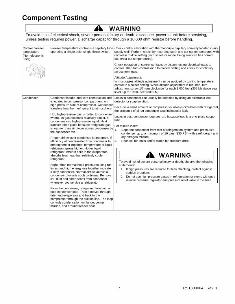
Control, freezer temperature (Non-electronic units)
Freezer temperature control is a capillary tube operating a single-pole, single-throw switch.
Check control calibration with thermocouple capillary correctly located in air-supply well. Perform check by recording cut-in and cut-out temperatures with control in middle setting (tech sheet for model being serviced has correct cut-in/cut-out temperatures).
Check operation of control contacts by disconnecting electrical leads to control. Then turn control knob to coldest setting and check for continuity across terminals.
Altitude Adjustment: In most cases altitude adjustment can be avoided by turning temperature control to a colder setting. When altitude adjustment is required, turn adjustment screw 1/7-turn clockwise for each 1,000 feet (305 M) above sea level, up to 10,000 feet (3050 M).
Condenser Condenser is tube-and-wire construction and is located in compressor compartment, on high-pressure side of compressor. Condenser transfers heat from refrigerant to atmosphere.
Hot, high-pressure gas is routed to condenser where, as gas becomes relatively cooler, it condenses into high-pressure liquid. Heat transfer takes place because refrigerant gas is warmer than air blown across condenser by the condenser fan.
Proper airflow over condenser is important. If efficiency of heat transfer from condenser to atmosphere is impaired, temperature of liquid refrigerant grows higher. Hotter liquid refrigerant, when it boils in the evaporator, absorbs less heat than relatively cooler refrigerant.
Higher than normal head pressures, long run times, and high energy use together indicate a dirty condenser. Normal airflow across a condenser prevents such problems. Remove lint, dust and other debris from condenser whenever you service a refrigerator.
From the condenser, refrigerant flows into a post-condenser loop. Then it moves through drier and evaporator and back to the compressor through the suction line. The loop controls condensation on flange, center mullion, and around freezer door.
Leaks in condenser can usually be detected by using an electronic leak detector or soap solution.
Because a small amount of compressor oil always circulates with refrigerant, the presence of oil on condenser also indicates a leak.
Leaks in post-condenser loop are rare because loop is a one-piece copper tube.
For minute leaks: 1. Separate condenser from rest of refrigeration system and pressurize
condenser up to a maximum of 16 bars (235 PSI) with a refrigerant and dry-nitrogen mixture.
2. Recheck for leaks and/or watch for pressure drop.
WARNING!
To avoid risk of severe personal injury or death, observe the following statements:
1. If high pressures are required for leak checking, protect against sudden eruptions.
2. Do not use high pressure gases in refrigeration systems without a reliable pressure regulator and pressure relief valve in the lines.

Component Testing
! WARNING To avoid risk of electrical shock, severe personal injury or death; disconnect power to unit before servicing, unless testing requires power. Discharge capacitor through a 10,000 ohm resistor before handling.
RS1300004 Rev. 1 8
Drier
Drier is located in machine compartment at outlet of post-condenser loop. It removes moisture from liquid refrigerant while passing refrigerant to capillary.
Drier must be replaced when system is opened for any reason. Before opening system, recover refrigerant for safe disposal. Do not debraze drier. Applying heat to remove drier drives moisture out of drier into system. Cut drier out of system using the following procedure: 1. Score capillary tube close to drier and break. 2. Reform tubes so you have space in which to use a large tubing cutter
on the drier. 3. Cut circumference of drier 1-1/4” (3 cm) below point at which
condenser inlet tube joins drier. Remove drier, leaving only its top brazed to tubing.
WARNING!
To avoid risk of severe personal injury or death; cut drier at correct location. Cutting drier in wrong place allows desiccant beads to scatter, creating a fall hazard. Clean up beads if spilled.
4. Apply heat-trap paste on post-condenser tubes above drier to protect grommets from high heat.
5. Debraze remaining part of drier and remove it from system. 6. Discard drier in safe place. Do not leave drier with customer. 7. If unit is in warranty, old drier accompanies warranty claim.
Evaporator Inner volume of evaporator allows liquid refrigerant to expand into refrigerant gas. Expansion cools evaporator, transferring heat from freezer to refrigerant. Passing through heat exchanger on its way to compressor, refrigerant gas picks up superheat from liquid refrigerant. Exchange assures complete vaporization of liquid refrigerant inside evaporator. Compressor pulls refrigerant gas through suction line to complete cycle.
Use electronic leak detector or solution of soap and water to check for leaks from evaporator. Presence of oil on evaporator also indicates a leak because some compressor oil always circulates with refrigerant. For minute leaks: 1. Separate evaporator from rest of system and pressurize condenser up
to a maximum of 10 bars (140 PSI) with a refrigerant and dry nitrogen combination.
2. Recheck for leaks and/or watch for pressure drop.
Heater, cavity Applied to back of ice and water cavity to prevent condensation on face of cavity.
Some models have spare heater foamed in place at factory. See tech sheet for model being serviced.
Check resistance across heater (for resistance values see tech sheet for model being serviced).
Heater, evaporator (defrost)
Activated when defrost thermostat or adaptive defrost control completes circuit through the heater.
Check resistance across heater. To check defrost system: 1. Thermocouple defrost thermostat and plug refrigerator into wattmeter. 2. Force unit into defrost mode (see “Electronic Testing”). Wattmeter
should read according to tech sheet. 3. When thermostat reaches specified temperature (see tech sheet), it
should interrupt power to heater. Motor, auger
Located behind ice bucket. Drives helix auger and cube crusher.
PSC (Permanent Split Capacitor) motor requiring a run capacitor.
Controlled by ice-actuator switch in series with freezer-door auger-interlock switch and cube/crushed ice switch.
Internal overload trips after about 90 seconds of continuous run. Resets in about 3 minutes.
Disconnect power, check windings with ohmmeter and verify ground.
Crushed/Cube Dispensing Models: With unit at room temperature, check resistance between wire leads (see tech sheet for your model).
Cube Dispensing Models: With unit at room temperature, check resistance between wire leads (see tech sheet for your model).
Component Testing
! WARNING To avoid risk of electrical shock, severe personal injury or death; disconnect power to unit before servicing, unless testing requires power. Discharge capacitor through a 10,000 ohm resistor before handling.
9 RS1300004 Rev. 1
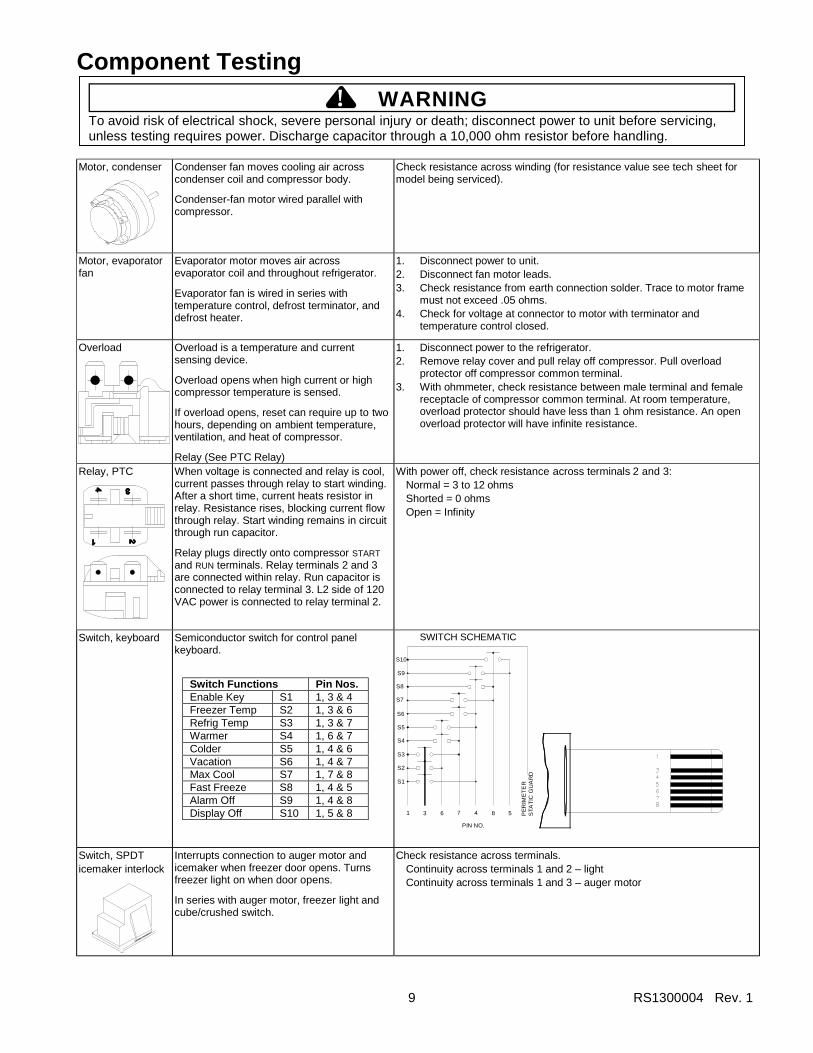
Motor, condenser
Condenser fan moves cooling air across condenser coil and compressor body.
Condenser-fan motor wired parallel with compressor.
Check resistance across winding (for resistance value see tech sheet for model being serviced).
Motor, evaporator fan
Evaporator motor moves air across evaporator coil and throughout refrigerator.
Evaporator fan is wired in series with temperature control, defrost terminator, and defrost heater.
1. Disconnect power to unit. 2. Disconnect fan motor leads. 3. Check resistance from earth connection solder. Trace to motor frame
must not exceed .05 ohms. 4. Check for voltage at connector to motor with terminator and
temperature control closed.
Overload
Overload is a temperature and current sensing device.
Overload opens when high current or high compressor temperature is sensed.
If overload opens, reset can require up to two hours, depending on ambient temperature, ventilation, and heat of compressor.
Relay (See PTC Relay)
1. Disconnect power to the refrigerator. 2. Remove relay cover and pull relay off compressor. Pull overload
protector off compressor common terminal. 3. With ohmmeter, check resistance between male terminal and female
receptacle of compressor common terminal. At room temperature, overload protector should have less than 1 ohm resistance. An open overload protector will have infinite resistance.
Relay, PTC
When voltage is connected and relay is cool, current passes through relay to start winding. After a short time, current heats resistor in relay. Resistance rises, blocking current flow through relay. Start winding remains in circuit through run capacitor.
Relay plugs directly onto compressor START and RUN terminals. Relay terminals 2 and 3 are connected within relay. Run capacitor is connected to relay terminal 3. L2 side of 120 VAC power is connected to relay terminal 2.
With power off, check resistance across terminals 2 and 3: Normal = 3 to 12 ohms Shorted = 0 ohms Open = Infinity
Switch, keyboard Semiconductor switch for control panel keyboard.
SWITCH SCHEMATIC
S10
S9
S8
S7
S6
S5
S4
S3
S2
S1
1 3 6
PIN NO.
7 4 8 5 PE
RIM
ET
ER
STA
TIC
GU
AR
D
Switch, SPDT icemaker interlock
Interrupts connection to auger motor and icemaker when freezer door opens. Turns freezer light on when door opens.
In series with auger motor, freezer light and cube/crushed switch.
Check resistance across terminals. Continuity across terminals 1 and 2 – light Continuity across terminals 1 and 3 – auger motor
Switch Functions Pin Nos. Enable Key S1 1, 3 & 4 Freezer Temp S2 1, 3 & 6 Refrig Temp S3 1, 3 & 7 Warmer S4 1, 6 & 7 Colder S5 1, 4 & 6 Vacation S6 1, 4 & 7 Max Cool S7 1, 7 & 8 Fast Freeze S8 1, 4 & 5 Alarm Off S9 1, 4 & 8 Display Off S10 1, 5 & 8

Component Testing
! WARNING To avoid risk of electrical shock, severe personal injury or death; disconnect power to unit before servicing, unless testing requires power. Discharge capacitor through a 10,000 ohm resistor before handling.
RS1300004 Rev. 1 10
Switch, crushed/cubed
Selects between cubed or crushed ice features.
Check resistance across terminals. Switch left
Middle terminal to left terminal 0 ohms Middle terminal to right terminal Infinity
Switch right Middle terminal to right terminal 0 ohms Middle terminal to left terminal Infinity
Switch, refrigerator light, freezer light, refrigerator fan
Completes circuit to allow indicated function. See tech sheet and wiring diagram for individual switch.
Check resistance across terminals. Switch arm down:
“NC” terminals closed “NO” terminals open
Switch arm up: “NC” terminals open “NO” terminals closed
Switch, power
SPDT
Electronic models only. Disconnects high-voltage board from power when off (open).
Unit ships with switch ON.
Check resistance across terminals. Switch OFF Infinity (open) Switch ON 0 ohms (short)
Switch, photosensitive
In series with cavity light switch and cavity light. Senses light. Disables cavity light during bright-light conditions.
Switch must not generate line conducted noise or radiate inference more than three feet on the AM, FM, VHF, or USH Frequency bands.
1. To check light sensor with cavity light switch on, cover light sensor eye. Cavity lamp should light at 50% illumination.
2. If lamp fails to light, activate water or ice-dispenser switch. Lamp should shine at full power and water or ice should be dispensed.
3. If light works with dispenser switch, disconnect power and replace photosensitive switch.
4. If lamp does not illuminate, disconnect power and check cavity lamp and socket.
Thermistor
Electronic units only. Senses temperatures in refrigerator and freezer compartments.
Check resistance across terminals. See tech sheet for resistance at specific temperatures.
Thermostat (Defrost Terminator)
Clipped to top of evaporator coil. Wired in series with freezer temperature control, defrost heater and evaporator-fan motor. Circuit is complete if evaporator-fan motor operates when cold.
Controls circuit from freezer temperature control, through evaporator fan to defrost heater. Opens and breaks circuit when terminator senses preset high temperature.
After terminator opens, it remains open until defrost cycle ends. When evaporator cools to preset low temperature, terminator closes again.
Test continuity across terminals. Volts .............................................. Watts ............................................. Current .......................................... Resistance across terminals Above 48° ±5°F............................ Below 15° ±7°F ........................... Between 48° ±5°F and 15° ±7°F ..
With power off and evaporator below freezing, thermostat should show continuity when checked with ohmmeter. See “Heater, evaporator (defrost)” entry for additional tests. 120/240 VAC 1000 watts 10/5 amps Open Closed Will stay in current state (open or closed) until either 48° ±6°F or 15° ±8°F is reached.
Icemaker See Appendix B for information.
Component Testing
! WARNING To avoid risk of electrical shock, severe personal injury or death; disconnect power to unit before servicing, unless testing requires power. Discharge capacitor through a 10,000 ohm resistor before handling.
11 RS1300004 Rev. 1
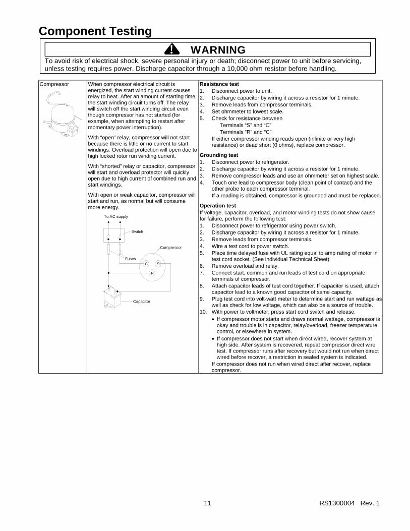
Compressor
When compressor electrical circuit is energized, the start winding current causes relay to heat. After an amount of starting time, the start winding circuit turns off. The relay will switch off the start winding circuit even though compressor has not started (for example, when attempting to restart after momentary power interruption).
With “open” relay, compressor will not start because there is little or no current to start windings. Overload protection will open due to high locked rotor run winding current.
With “shorted” relay or capacitor, compressor will start and overload protector will quickly open due to high current of combined run and start windings.
With open or weak capacitor, compressor will start and run, as normal but will consume more energy.
C
R
SFuses
Capacitor
Compressor
Switch
To AC supply
Resistance test 1. Disconnect power to unit. 2. Discharge capacitor by wiring it across a resistor for 1 minute. 3. Remove leads from compressor terminals. 4. Set ohmmeter to lowest scale. 5. Check for resistance between
Terminals “S” and “C” Terminals “R” and “C”
If either compressor winding reads open (infinite or very high resistance) or dead short (0 ohms), replace compressor.
Grounding test 1. Disconnect power to refrigerator. 2. Discharge capacitor by wiring it across a resistor for 1 minute. 3. Remove compressor leads and use an ohmmeter set on highest scale. 4. Touch one lead to compressor body (clean point of contact) and the
other probe to each compressor terminal. If a reading is obtained, compressor is grounded and must be replaced.
Operation test If voltage, capacitor, overload, and motor winding tests do not show cause for failure, perform the following test: 1. Disconnect power to refrigerator using power switch. 2. Discharge capacitor by wiring it across a resistor for 1 minute. 3. Remove leads from compressor terminals. 4. Wire a test cord to power switch. 5. Place time delayed fuse with UL rating equal to amp rating of motor in
test cord socket. (See individual Technical Sheet). 6. Remove overload and relay. 7. Connect start, common and run leads of test cord on appropriate
terminals of compressor. 8. Attach capacitor leads of test cord together. If capacitor is used, attach
capacitor lead to a known good capacitor of same capacity. 9. Plug test cord into volt-watt meter to determine start and run wattage as
well as check for low voltage, which can also be a source of trouble. 10. With power to voltmeter, press start cord switch and release.
• If compressor motor starts and draws normal wattage, compressor is okay and trouble is in capacitor, relay/overload, freezer temperature control, or elsewhere in system.
• If compressor does not start when direct wired, recover system at high side. After system is recovered, repeat compressor direct wire test. If compressor runs after recovery but would not run when direct wired before recover, a restriction in sealed system is indicated.
If compressor does not run when wired direct after recover, replace compressor.

RS1300004 Rev. 1 12
Troubleshooting Procedure
! WARNINGTo avoid risk of electrical shock severe personal injury or death; disconnect power to unit before servicing, unlesstesting requires power. Discharge capacitor through a 10,000 ohm resistor before handling. Wires removed duringdisassembly must be placed on the correct terminals to ensure proper grounding and polarization.
Troubleshooting Chart: Refrigerator Symptoms Related to Problems
Symptom Possible Causes Corrective ActionNo power to unit. Check for power at outlet. Check fuse
box or circuit breaker for blown fuse ortripped breaker. Replace or reset.
Power switch either off or faulty. Check switch at high-voltage board(electronic models only).
Faulty service cord. Check with test light at unit. If no circuitwhen current is present at outlet,replace or repair.
Low voltage. Check input voltage for proper level.Take appropriate action to correctvoltage supply problem.
Faulty freezer temperature control. Make sure all connections are tight andsolid. Jumper across control. If unitruns, replace control.
Faulty timer. Check with test light. Replace ifnecessary.
Faulty high-voltage board orcompressor/condenser-fan relay(electronic models only) or defrosttimer (non-electronic models).
Check board, relay, or timer. Replace ifnecessary.
Faulty compressor. Check compressor motor windings foropen/short. Perform compressor directwiring test. Replace if necessary.
Unit does not run.
Faulty overload or relay. Check overload for continuity.NOTE: Ensure compressor and
overload are below triptemperature before testing.
Check relay resistance across terminals2 and 3 (consult tech sheet forcorrect value).
Replace if necessary.Excessive door opening. Consumer education.Shelves overloaded. Consumer education.Hot food placed in cabinet. Consumer education.Refrigerator temperature control settoo warm.
Adjust control to colder setting.
Poor door seal. Level cabinet. Adjust hinges. Replacedoor gasket if necessary.
Refrigerator airflow restricted orstopped.
Check damper operation; replacedamper if faulty. Check temp-control;adjust or replace as required. Checkevaporator fan; replace if necessary.
Interior light stays on. Check switch. Replace if necessary, oradjust door for proper switchengagement.
Faulty evaporator fan. Check fan switch, fan and wiring.Replace if necessary.
Refrigerator sectiontoo warm.
Faulty compressor. Replace compressor.

13 RS1300004 Rev. 1
Troubleshooting Procedure
! WARNINGTo avoid risk of electrical shock severe personal injury or death; disconnect power to unit before servicing, unlesstesting requires power. Discharge capacitor through a 10,000 ohm resistor before handling. Wires removed duringdisassembly must be placed on the correct terminals to ensure proper grounding and polarization.
Symptom Possible Causes Corrective ActionRefrigerator temperature control settoo cold.
Adjust as needed.Refrigerator section toocold.
Refrigerator airflow not properlyadjusted.
Adjust beverage chiller and chiller freshtemperature controls. Make sure deliboot seals against air-supply orifice.
Temperature controls set too warm. Adjust as needed.Poor door seals. Level cabinet; adjust hinges. Replace
door gasket(s) if necessary.Dirty condenser or obstructed grille. Clean.Faulty temperature controls. Check; replace if necessary.Defrost malfunction. Check evaporator for heavy frost.
Freezer and refrigeratorsections too warm.
Refrigerant shortage or flowrestriction.
Check for leak or restriction. Repair,evacuate, and recharge system.
Temperature control set too cold. Adjust.Freezer section toocold. Faulty freezer temperature control. Test control. Replace if necessary.
Temperature control set too cold. Adjust.Faulty temperature control. Test. Replace if defective.Dirty condenser or obstructed grille. Clean.Poor door seal. Level cabinet; adjust hinges. Replace
door gasket(s) if necessary.Interior light stays on. Check switch. Make sure door activates
switch. Adjust, replace as necessary.Faulty condenser fan or evaporatorfan.
Check fan switch, fan and wiring.Replace if necessary.
Refrigerant shortage or flowrestriction.
Check for leak or restriction. Repair,evacuate, and recharge system.
Refrigerant overcharge. Check for overcharge. Evacuate andrecharge system.
Unit runs continuously.
Air in system. Check for low-side air leak. Repair,evacuate, and recharge system.
Unit runs continuously.Temperature normal orwarm.
Ice on evaporator. See “Ice on Evaporator.”
Unit runs continuously.Temperature too coldor too warm.
Faulty defrost timer. Faulty coldcontrol. Faulty defrost terminator.Faulty high-voltage board(electronic units).
Check timer, cold control, terminatorand/or high-voltage board. Replacefaulty components.

RS1300004 Rev. 1 14
Troubleshooting Procedure
! WARNINGTo avoid risk of electrical shock severe personal injury or death; disconnect power to unit before servicing, unlesstesting requires power. Discharge capacitor through a 10,000 ohm resistor before handling. Wires removed duringdisassembly must be placed on the correct terminals to ensure proper grounding and polarization.
Symptom Possible Causes Corrective ActionLoose flooring or floor not firm. Repair floor or brace floor.Cabinet not level. Level cabinet.Tubing in contact with cabinet, othertubing or other metal.
Adjust tubing.
Drain pan vibrating. Adjust drain pan.Fan hits another component. Ensure fan is properly aligned,
associated hardware is tight and notworn. Tighten or replace as necessary.
Fan motor bearings worn. Check fan motor for loss of lubricantand worn bearings. Replace ifnecessary.
Compressor grommets worn ormissing. Mounting hardware looseor missing.
Replace grommets. Tighten hardwareas required.
Noisy operation.
Free or loose parts cause noiseduring operation.
Inspect unit for parts that may haveworked loose. Check for loose ormissing screws. Replace, repair asnecessary.
Defrost thermostat faulty. Check thermostat. Replace ifnecessary.
Evaporator fan faulty. Check. Replace if necessary.Defrost heater remains open. Check defrost heater continuity.
Replace if faulty.Defrost timer faulty. Check timer. Replace if necessary.
Frost or ice onevaporator.
Open wire or connector. Check wiring and connectors. Repair asnecessary.
Loose wire or thermostatconnections.
Check wiring and connections. Repairas necessary.
Supply voltage out of spec. Check input voltage. Correct supplyproblems.
Overload protector open. Check overload protector for continuity.If open, replace overload.
NOTE: Ensure overload andcompressor are below triptemperature before testing.
Faulty compressor motor capacitor. Check capacitor for open/short.Replace if necessary.
NOTE: Discharge capacitor beforehandling.
Restricted condenser air flow. Check condenser and grille for dirt.Clean as required.
Unit starts and stopsfrequently (cycles onand off).
Refrigerant shortage or restriction. Check for leak or restriction. Repair,evacuate, and recharge system.

15 RS1300004 Rev. 1
Troubleshooting Procedure
! WARNINGTo avoid risk of electrical shock severe personal injury or death; disconnect power to unit before servicing, unlesstesting requires power. Discharge capacitor through a 10,000 ohm resistor before handling. Wires removed duringdisassembly must be placed on the correct terminals to ensure proper grounding and polarization.
Variation from NormalCondition
Suction Press Head PressT1
Inlet TempT2
Outlet TempT3
Suction TempWattage
RefrigerantOvercharge
Increase Increase Warmer Warmer Colder Increase
RefrigerantShortage
Decrease Decreaseor Increase
Colder Warmer Warmer Decrease
PartialRestriction
DecreaseDecrease
or IncreaseColder Warmer Warmer Decrease
Airin System Near Normal Increase Warmer Warmer Warmer Increase
Low AmbientInstallation
Decrease Decrease Colder Warmer Warmer Decrease
HighAmbientInstallation
Increase Increase Warmer Warmer Warmer Increase
AdditionalHeat Load Increase Increase Warmer Warmer Warmer Increase
InefficientCompressor
IncreaseNormal
or DecreaseWarmer
or ColderWarmer Warmer Decrease
Troubleshooting Chart: Sealed-System Conditions
RS1300004 Rev. 1 16
Troubleshooting Procedure
! WARNINGTo avoid risk of electrical shock severe personal injury or death; disconnect power to unit before servicing, unlesstesting requires power. Discharge capacitor through a 10,000 ohm resistor before handling. Wires removed duringdisassembly must be placed on the correct terminals to ensure proper grounding and polarization.
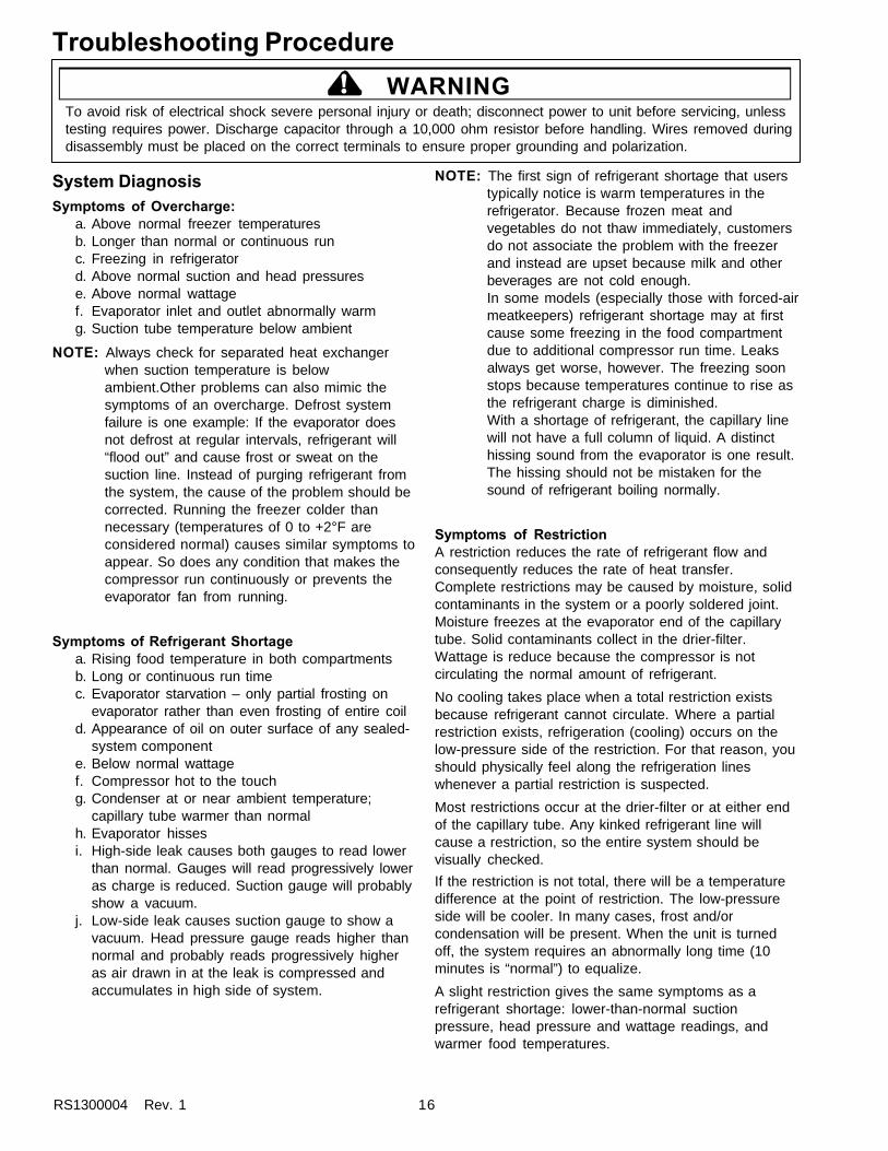
System DiagnosisSymptoms of Overcharge:
a. Above normal freezer temperaturesb. Longer than normal or continuous runc. Freezing in refrigeratord. Above normal suction and head pressurese. Above normal wattagef. Evaporator inlet and outlet abnormally warmg. Suction tube temperature below ambient
NOTE: Always check for separated heat exchangerwhen suction temperature is belowambient.Other problems can also mimic thesymptoms of an overcharge. Defrost systemfailure is one example: If the evaporator doesnot defrost at regular intervals, refrigerant will“flood out” and cause frost or sweat on thesuction line. Instead of purging refrigerant fromthe system, the cause of the problem should becorrected. Running the freezer colder thannecessary (temperatures of 0 to +2°F areconsidered normal) causes similar symptoms toappear. So does any condition that makes thecompressor run continuously or prevents theevaporator fan from running.
Symptoms of Refrigerant Shortagea. Rising food temperature in both compartmentsb. Long or continuous run timec. Evaporator starvation – only partial frosting on
evaporator rather than even frosting of entire coild. Appearance of oil on outer surface of any sealed-
system componente. Below normal wattagef. Compressor hot to the touchg. Condenser at or near ambient temperature;
capillary tube warmer than normalh. Evaporator hissesi. High-side leak causes both gauges to read lower
than normal. Gauges will read progressively loweras charge is reduced. Suction gauge will probablyshow a vacuum.
j. Low-side leak causes suction gauge to show avacuum. Head pressure gauge reads higher thannormal and probably reads progressively higheras air drawn in at the leak is compressed andaccumulates in high side of system.
NOTE: The first sign of refrigerant shortage that userstypically notice is warm temperatures in therefrigerator. Because frozen meat andvegetables do not thaw immediately, customersdo not associate the problem with the freezerand instead are upset because milk and otherbeverages are not cold enough.In some models (especially those with forced-airmeatkeepers) refrigerant shortage may at firstcause some freezing in the food compartmentdue to additional compressor run time. Leaksalways get worse, however. The freezing soonstops because temperatures continue to rise asthe refrigerant charge is diminished.With a shortage of refrigerant, the capillary linewill not have a full column of liquid. A distincthissing sound from the evaporator is one result.The hissing should not be mistaken for thesound of refrigerant boiling normally.
Symptoms of RestrictionA restriction reduces the rate of refrigerant flow andconsequently reduces the rate of heat transfer.Complete restrictions may be caused by moisture, solidcontaminants in the system or a poorly soldered joint.Moisture freezes at the evaporator end of the capillarytube. Solid contaminants collect in the drier-filter.Wattage is reduce because the compressor is notcirculating the normal amount of refrigerant.
No cooling takes place when a total restriction existsbecause refrigerant cannot circulate. Where a partialrestriction exists, refrigeration (cooling) occurs on thelow-pressure side of the restriction. For that reason, youshould physically feel along the refrigeration lineswhenever a partial restriction is suspected.
Most restrictions occur at the drier-filter or at either endof the capillary tube. Any kinked refrigerant line willcause a restriction, so the entire system should bevisually checked.If the restriction is not total, there will be a temperaturedifference at the point of restriction. The low-pressureside will be cooler. In many cases, frost and/orcondensation will be present. When the unit is turnedoff, the system requires an abnormally long time (10minutes is “normal”) to equalize.
A slight restriction gives the same symptoms as arefrigerant shortage: lower-than-normal suctionpressure, head pressure and wattage readings, andwarmer food temperatures.

17 RS1300004 Rev. 1
Troubleshooting Procedure
! WARNINGTo avoid risk of electrical shock severe personal injury or death; disconnect power to unit before servicing, unlesstesting requires power. Discharge capacitor through a 10,000 ohm resistor before handling. Wires removed duringdisassembly must be placed on the correct terminals to ensure proper grounding and polarization.
NOTE: If a total restriction occurs on the discharge sideof the compressor, head-pressure and wattagereadings may be higher than normal – but onlywhile the compressor pumps the low side outand the restriction resides between thecompressor and the first half of the condenser.
To diagnose for a restriction versus a refrigerantshortage, first discharge the system. Then replace thedrier-filter, evacuate, and recharge with the specifiedquantity of the correct refrigerant.
If, after doing so, the unit performs normally, threepossibilities exist: 1) refrigerant loss; 2) partiallyrestricted drier-filter; 3) moisture in system.If, after doing so, the symptoms do not change, you mayhave a restricted capillary, condenser or possibly akinked line. You must find the restriction and correct it.
What about gauge readings? If the restriction is on thelow side, suction pressure will probably be in vacuumand head pressure will be near normal. If the restrictionis on the high side, suction pressure, again, will probablybe in vacuum. Head pressure will be higher than normal– but only during the pump-out period, as noted above.In any case it takes longer than normal (10 minutes) forpressures to equalize after the compressor stops.
Symptoms of Air in SystemThe presence of air in a sealed system causesinefficient cooling. Longer-than-normal compressor runtimes result. Where enough air is present, thecompressor runs continuously and the system doesn’tcool at all. Head pressure readings are abnormally highbecause air does not mix with refrigerant butnevertheless takes up space inside the system.One way to determine if air is in the system is to readthe head pressure gauge when the unit is shut downand evaporator and condenser are at the sametemperature. When these conditions have beenachieved, take the temperature of the condenser outlettube. Condenser-outlet temperature should be within 3°or 4°F of what the Pressure-Temperature Relation(PTR) chart shows for the given idle head pressure. Ifthe condenser-outlet temperature is substantially lowerthan the PTR chart says it ought to be, air is present inthe system.
When air in the system is suspected, a thorough leak-check is necessary. The leak, if it exists, must beidentified and properly sealed. Once the leak has beensealed, the system must be discharged; the drier mustbe replaced; the system must be evacuated and thenrecharged with a correct amount of the specifiedrefrigerant.
Do not attempt to save time by merely purging air fromthe system. Should you do so, you will have aninefficient, incorrectly charged unit that will soon givemore trouble.
Symptoms Due to Improper Ambient TemperatureLower ambient air temperature reduces the condensingtemperature and therefore reduces the temperature ofliquid entering the evaporator. The increase inrefrigeration effect due to operation in a low ambientresults in decreased power consumption and run time.Lower ambients also reduce cabinet heat leak, a factpartially responsible for reduced power consumption andrun time.
An increase in refrigeration effect cannot be expectedbelow a certain minimum ambient temperature. Thatminimum temperature varies with the type and design ofthe product. Generally, ambient temperatures cannot belower than 55°F without reducing operational efficiency.
Refrigerators installed in ambients below 55°F do notperform as well because pressures within the systemare generally reduced and unbalanced. This means thatlower head pressures force less refrigerant through thecapillary, resulting in symptoms like those produced by arefrigerant shortage. The lower the ambienttemperature, the more pronounced these symptomsbecome. At a point where ambient temperature is lowerthan the cut-in of the temperature control, thecompressor won’t run. Defrost drain taps freeze upwhere ambient temperatures are below 32°F.Conversely, the higher the ambient temperature, thehigher system head pressure must be in order to raisehigh-side refrigerant temperature above that of theambient, condensing medium. In other words: headpressures must rise as the ambient temperature rises.Where ambient temperatures are too high, operatingefficiency is again reduced.
Heavy Heat LoadIncreased heat loads result when an abnormally largesupply of foods is laid in, as is typical after the weeklyshopping. Other factors contributing to an increasedheat load include excessive door openings, poor doorsealing, failure of an interior light to shut off, etc.
An increase in heat absorbed by refrigerant in theevaporator affects the temperature and pressure of gasreturning to the compressor. Compartmenttemperatures, power consumption, discharge andsuction pressures are all affected by heat load.Pressures will be higher than normal under a heavy heatload.

Service Procedures
RS1300004 Rev. 1 18
Service EquipmentBulleted below are items needed for proper service ofHFC134a systems. Before attempting service ofHFC134a systems, make sure that all equipment youintend to use is certified by the manufacturer to becompatible with HFC134a and ester oil systems.
NOTE: Items shown in italics must be used exclusivelywith HFC134a systems.
• Evacuation pumpCheck with vacuum pump supplier to verify equipmentis compatible for HFC134a. Robinair, Model 15600, 2stage, 170 litres (6 cubic feet) per minute pump isrecommended.
• Four-way manifold gauge set, with low-loss hoses• Leak detector• Charging cylinder• Refrigerant scale• Line piercing saddle valve (Schroeder valve)• Swagging tools• Flaring tools• Tubing cutter• Flux• Sil-Fos• Silver solder• Heat-trap paste• Oil for swagging and flaring
Use only part #R0157532• Copper tubing
Use only part #R0174075 and #R0174076• Dry nitrogen
99.5% minimum purity, with -40°C (-40°F) or lowerdew point.
• Crimp tool• Tubing bender• Micron vacuum gauge• Process tube adaptor kit• ICI appliance-grade HFC134a
! WARNINGTo avoid risk of electrical shock, severe personal injury or death; disconnect power to unit before servicing, unlesstesting requires power. Discharge capacitor through a 10,000 ohm resistor before handling. Wires removed duringdisassembly must be placed on the correct terminals to ensure proper grounding and polarization.
Line Piercing Valves (Schroeder valves)Seals must be HFC134a and ester-oil compatible. Linepiercing valves can be used for diagnosis but are notsuitable for evacuation or charging because they pokeholes in tubing. Do not leave access valves on systembecause they leak. HFC134a molecules are smallerthan other refrigerant molecules, so 134a will leak whereother refrigerants would not.
Open LinesDuring any procedure on sealed system, never leavelines open to atmosphere. Open lines allow water vaporto enter system, making proper evacuation moredifficult.
Brazing
CAUTION!To avoid risk of personal injury or property damage,protect yourself and the unit from heat when brazing.
• Protect yourself by wearing goggles, gloves and otherpersonal protective equipment.
• Protect components by using heat-trap paste, heatsinks and other means to isolate heat.
• Satisfactory results require cleanliness, experience,and use of proper materials and equipment.
• Connections to be brazed must be properly sized, freeof rough edges, and clean.
Acceptable Brazing Materials:• Copper-to-copper: SIL-FOS (alloy of 15 percent
silver, 80 percent copper, and 5 percentphosphorous). Use without flux. Recommendedbrazing temperature is approximately 760°C (1400°F).
NOTE: Do not use SIL-FOS for copper-to-steel joints.
• Copper-to-steel: SILVER SOLDER (alloy of 30percent silver, 38 percent copper, 32 percent zinc).Use with fluoride based flux. Recommended brazingtemperature is approximately 649°C (1200°F).
• Steel-to-steel: SILVER SOLDER (see copper-to-steel).
• Brass-to-copper: SILVER SOLDER (see copper-to-steel).
• Brass-to-steel: SILVER SOLDER (see copper-to-steel).

19 RS1300004 Rev. 1
Service Procedures
! WARNINGTo avoid risk of electrical shock, severe personal injury or death; disconnect power to unit before servicing, unlesstesting requires power. Discharge capacitor through a 10,000 ohm resistor before handling. Wires removed duringdisassembly must be placed on the correct terminals to ensure proper grounding and polarization.
HFC134a Service InformationHFC134a refrigerant is an alternative to CFC12refrigerant. HFC134a has an ozone depletion potential(ODP) factor of 0.0 and a global warming potential(GWP) factor of 0.27. HFC134a has acceptable toxicitylevels and is not flammable.
Health, Safety, & Handling CFC12 HFC134aAllowable exposure limit 1,000 ppm Same
Vapor exposure to skin No effect SameLiquid exposure to skin Can cause frostbite SameVapor exposure to eye Very slight eye
irritantSame
Liquid exposure to eye Can cause frostbite SameAbove minimum exposurelimit
Can causeAsphyxiation,Tachycardia, andCardia Arrhythmias
Same
Safety and handling Wear appropriateskin and eyeprotection. Usewith adequateventilation.
Same
Spill management Remove orextinguish ignitionor combustionsources. Evacuateor ventilate area.
Same
Fire explosion hazards May decompose ifin contact withflames and heatingelements.Container mayexplode if heateddue to resultantpressure rise.Produces toxicbyproducts whenburned.
Same
Disposal procedures Recycle or reclaim. Same
Table 1
Properties/Characteristics CFC12 HFC134aOzone Depletion Potential 1.0 0.0Global Warming Potential 3.2 0.27Molecular weight 121 102Boiling point at 1 atmosphere -22°F (-30°C) -15°F (-26°C)Vapor pressure at 77°F (25°C) 80 psig 82 psigLiquid density at 77°F (25°C) 82 lb/ft 3 75 lb/ft 3
Flammability No NoHigh-side system operatingPressure at 65°F (18°C)
HFC134a approximately 3 psighigher than CFC12
Low-side system operatingPressure at 65°F (18°C)
HFC134a approximately 2 psiglower than CFC12
Table 2
Health, Safety, and HandlingHealth, safety and handling considerations for HFC134Aare virtually no different than those for CFC12 (SeeTable 1). Still, HFC134a is not interchangeable withCFC12. Significant differences between HFC134a andCFC12 exist (See Table 2) and must be consideredwhen servicing refrigeration systems.
Service Precautions• Allow no trace of other refrigerants in HFC134a
systems. Chlorinated molecules in other refrigerants(such as CFC12) plug the capillary.
• Ester oil is used in HFC134a systems. Do not usemineral oil. HFC134a and mineral oil do not mix. Ifmineral oil is used with HFC134a, lubricant will notreturn to compressor and compressor will fail as aresult. If significant amount of oil is lost fromcompressor, do not add oil but replace it instead.
• Take every care to keep moisture out of HFC134asystem. Never leave compressor or system open toatmosphere for more than 10 minutes. Moisture inHFC134a system reacts with compressor oil andgenerates acid.
• Ester oil in HFC134a systems is so receptive tomoisture that by the time poor system performance isdetected, oil is saturated with moisture.
• HFC-134a compatible copper tubing, Amana part No.R0174075 (1/4” O.D x 18” length) and part No.R0174076 (5/16” O.D. x 24” length), must be usedwhen replacement tubing is required.
• To avoid system contamination, Towerdraw E610evaporating oil (Amana part No. R0157532) must beused when flaring, swaging or cutting refrigerationtubing.
• CFC12 has high tolerance for system processingmaterials such as drawing compounds, rust inhibitorsand cleaning compounds. HFC134a has none. Suchmaterials are not soluble in HFC134a. When washedfrom system surfaces by ester oils, they accumulateand plug capillary tube.
• Always replace compressor when performing low-sideleak repair.
• Always replace drier filter with service drier filter, partNo. B2150504. Never use any other drier.
NOTE: Before attempting removal of drier, read “Drier”procedure in this manual.
• HFC134a compatible copper tubing, part #R0174075and part #R0174076 must be used when replacingtubing.
• Avoid system contamination by using Towerdraw E610evaporating oil, part # R0157532, when flaring,swagging, or cutting refrigeration tubing.

Service Procedures
RS1300004 Rev. 1 20
! WARNINGTo avoid risk of electrical shock, severe personal injury or death; disconnect power to unit before servicing, unlesstesting requires power. Discharge capacitor through a 10,000 ohm resistor before handling. Wires removed duringdisassembly must be placed on the correct terminals to ensure proper grounding and polarization.
Sealed-System ServiceExpelling the ChargeWhen diagnosis is complete and a need to open thesealed system is positively identified, safe capture anddisposal of the refrigerant becomes the first operation.
NOTE: According to federal law, effective July 1, 1992,it is the responsibility of the service technician tocapture refrigerant for safe disposal.
DehydrationWhen moisture gets into a sealed refrigeration system,heat from compressor and motor causes the moisture toreact chemically with refrigerant and oil. Hydrochloricand hydrofluoric acids are formed by the process. Theacids break down insulation on motor windings andcorrode compressor working parts.
Compressor failure can be one result. In addition,sludge (a residue of the chemical reaction) coats allsurfaces inside the sealed system. Eventually, sludgebuildup restricts refrigerant flow through the capillarytube and ruins system performance.To prevent component damage and preserve systemperformance, sealed systems contaminated withmoisture must be thoroughly dehydrated. Proper systemdehydration entails three steps:
a. Test for leaks and restrictions, and repair asnecessary.
b. Evacuate the system.c. Charge the system.
LeaksIt is important to check sealed system for refrigerantleaks. Undetected leaks can lead to repeated servicecalls and eventually result in system contamination,restrictions, and premature compressor failure.
DANGER!To avoid risk of severe personal injury or deathcaused by explosion. Never use oxygen or acetyleneto pressure test or clean out a refrigeration sysem.Free oxygen explodes on contact with oil. Acteylenewill explode spontaneously when put under pressure.
Leak-testing Charged SystemsRefrigerant leaks are best detected with halide orelectronic leak detectors. Proceed as follows:
1. Stop the operation (turn refrigerator off).2. Disconnect unit from power.3. Hold leak detector’s refrigerant “sniffer” as close to
system tubing as possible while you check all piping,joints, and fittings.
4. Use soap suds to check areas leak detector cannotreach or reliably test.
Leak-testing Systems with No Charge1. Connect cylinder of nitrogen, through gauge
manifold, to process tube of compressor and liquidline strainer.
2. Open valves on nitrogen cylinder and gaugemanifold. Allow pressure to build within sealedsystem.
3. Check for leaks using soap suds.
If a leak is detected in tubing, replace the tubing. If aleak is detected in either coil, replace the faulty coil.
If a leak is detected in a brazed joint, do not to attemptto repair by applying more braze. Instead, the joint mustbe debrazed and disassembled, cleaned, reassembledand rebrazed. Capture refrigerant charge (if system ischarged) before starting your repair.
RestrictionsSymptomsRestrictions in sealed systems most often occur at thecapillary tube or filter drier but can exist anywhere onliquid side of system.
Restrictions reduce refrigerant flow and rate of heatremoval. Wattage drops because the compressor is notcirculating a normal amount of refrigerant.Common causes of total restrictions are moisture,poorly soldered joints, and solid contaminants. Moisturefreezes at the evaporator end of the capillary tube. Solidcontaminants collect in the filter drier.
If restriction is on the low side, suction pressure will bein a vacuum and head pressure will be near normal.
If restriction is on the high side, suction pressure will bein a vacuum and head pressure will be higher thannormal during the pump-out cycle.
Refrigeration occurs on the low-pressure side of apartial restriction. There will be a temperature differenceat the point of restriction. Frost and/or condensation willbe present in most cases at the point of restriction. Also,the system requires more time to equalize.
21 RS1300004 Rev. 1
Service Procedures
! WARNINGTo avoid risk of electrical shock, severe personal injury or death; disconnect power to unit before servicing, unlesstesting requires power. Discharge capacitor through a 10,000 ohm resistor before handling. Wires removed duringdisassembly must be placed on the correct terminals to ensure proper grounding and polarization.
Slight or partial restrictions can give the same symptomsas refrigerant shortage, including lower-than-normalback pressure, head pressure and wattage readings.Inside the unit, temperatures are above normal.
Total restriction on the discharge side of the compressor(when the restriction is between the compressor and thefirst half of the condenser) results in higher-than-normalhead pressure and wattage while the low side is beingpumped out.
Testing for RestrictionsTo determine if a restriction exists:
1. Attach gauge and manifold between suction anddischarge sides of sealed system.
2. Turn unit on and allow pressure on both sides tostabilize. Inspect condenser side of system. Tubingon condenser should be warm and temperatureshould be equal throughout (no sudden drops at anypoint along tubing).• If temperature of condenser tubing is consistent
throughout, go to step 4.• If temperature of condenser tubing drops suddenly
at any point, tubing is restricted at point oftemperature drop (if restriction is severe, frostmay form at point of restriction and extend downin direction of refrigerant flow in system). Go tostep 5.
3. Visually check system for kink(s) in refrigerationtubing that could cause the restriction. Correctkink(s) and repeat step 2.
4. Turn unit off and determine how long it takes high-pressure and low-pressure gauges to equalize:• If pressure equalization takes longer than 10
minutes, a restriction exists in the capillary tube ordrier filter. Go to step 5.
• If pressure equalization takes less than 10minutes, system is not restricted. Check for otherpossible causes of malfunction.
5. Recover refrigerant in sealed system.
NOTE: Before opening any refrigeration system,capture refrigerant for safe disposal.
6. Disconnect unit from power.• Protect yourself by wearing goggles, gloves and
other personal protective equipment.• Protect components by using heat-trap paste,
heat sinks and other means to isolate heat.7. Remove and replace restricted device.8. Evacuate and charge system per the following
instructions:
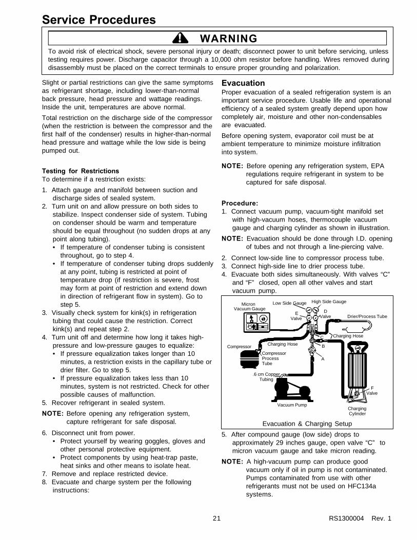
EvacuationProper evacuation of a sealed refrigeration system is animportant service procedure. Usable life and operationalefficiency of a sealed system greatly depend upon howcompletely air, moisture and other non-condensablesare evacuated.
Before opening system, evaporator coil must be atambient temperature to minimize moisture infiltrationinto system.
NOTE: Before opening any refrigeration system, EPAregulations require refrigerant in system to becaptured for safe disposal.
Procedure:1. Connect vacuum pump, vacuum-tight manifold set
with high-vacuum hoses, thermocouple vacuumgauge and charging cylinder as shown in illustration.
NOTE: Evacuation should be done through I.D. openingof tubes and not through a line-piercing valve.
2. Connect low-side line to compressor process tube.3. Connect high-side line to drier process tube.4. Evacuate both sides simultaneously. With valves “C”
and “F” closed, open all other valves and startvacuum pump.
Vacuum Pump
.6 cm CopperTubing
CompressorCompressorProcessTube
Charging Hose
MicronVacuum Gauge
Low Side Gauge
EValve
B
DValve
High Side Gauge
Charging Hose
Drier/Process Tube
FValve
ChargingCylinder
C
A
Evacuation & Charging Setup
5. After compound gauge (low side) drops toapproximately 29 inches gauge, open valve “C” tomicron vacuum gauge and take micron reading.
NOTE: A high-vacuum pump can produce goodvacuum only if oil in pump is not contaminated.Pumps contaminated from use with otherrefrigerants must not be used on HFC134asystems.

Service Procedures
RS1300004 Rev. 1 22
6. Continue evacuating system until vacuum gaugeregisters 600 microns.
7. At 600 microns, close valve “A” to vacuum pump andallow micron reading in system to balance. Micronlevel will rise.• If micron level stabilizes at 1000 microns or below
within 2 minutes, system is ready to be charged.• If micron level rises above 1000 microns and
stabilizes, open valve “A” and continueevacuating.
• If micron reading rises rapidly and does notstabilize, a leak exists in the system.
8. If system leaks, proceed as follows:a. Close valve “A” and valve “C”. Invert charging
cylinder and open valve “F” to add partial chargefor purpose of leak checking.
b. Using a leak detector or other means, checksystem throughly to identify leak(s).
c. After locating leak(s), capture refrigerant, repairleak(s), and begin at Step 1.
ChargingNOTE: Size of refrigerant charge in capillary-tube
systems is critical. Exact amount is required forproper system performance. See tech sheet orunit serial plate for correct refrigerant charge.Do not use refrigerant other than that shown onserial plate.
NOTE: Do not use captured or recycled refrigerant inAmana units. Captured or recycled refrigerantvoids any warranty.
Procedure:1. Evacuate system thoroughly per instructions above.2. Referring to illustration at left, close valves “A”
(vacuum pump), “C” (vacuum gauge) and “E”(low-side manifold gauge).
3. Set charging cylinder on a refrigerant scale.4. Open valve “F” (charging cylinder) and let exact
amount of refrigerant flow from cylinder into system.Close valve.Low-side gauge pressure should rise shortly afteropening charging cylinder valve as system pressureequalizes through capillary tube.If pressure does not equalize, a restriction typicallyexists at capillary/drier braze joint.
5. If pressure equalizes, open valve “E” (low-sidemanifold gauge) and pinch off high-side drierprocess tube.
6. Start compressor and draw remaining refrigerantfrom charging hoses and manifold into compressorthrough compressor process tube.
7. To check high side, pinch off drier process tube.Close valve “D” (high-side gauge). If high-sidepressure rises, repeat high-side pinch-off and openvalve “D”. Repeat until high-side pinch-off does notleak.
8. Pinch off compressor process tube and removecharging hose. Braze stub closed while compressoris operating.
9. Disconnect power. Remove charging hose and brazehigh-side drier process tube closed.
10. Recheck for refrigerant leaks.
Drier ReplacementDrier must be replaced when system is opened for anyreason. Before opening system, recover refrigerant forsafe disposal.
Do not debraze drier. Applying heat to remove drierdrives moisture out of drier into system. Cut drier out ofsystem using the following procedure.
1. Score capillary tube close to drier and break.2. Reform tubes so you have space in which to use a
large tubing cutter on the drier.
WARNING!To avoid risk of severe personal injury or death; cutdrier at correct location. Cutting drier in wrong placeallows dessicant beads to scatter, creating a fallhazard. Clean up beads if spilled.
3. Cut circumference of drier 1-1/4” (3 cm) below pointat which condenser inlet tube joins drier.
4. Remove drier, leaving only its top brazed to systemtubing.
5. Apply heat-trap paste on post-condenser tubesabove drier to protect grommets from high heat.
6. Debraze remaining part of drier and remove it fromsystem.
7. Discard drier in safe place. Do not leave drier withcustomer.
8. If unit is in warranty, old drier accompanies warrantyclaim.
! WARNINGTo avoid risk of electrical shock, severe personal injury or death; disconnect power to unit before servicing, unlesstesting requires power. Discharge capacitor through a 10,000 ohm resistor before handling. Wires removed duringdisassembly must be placed on the correct terminals to ensure proper grounding and polarization.

23 RS1300004 Rev. 1
Service Procedures
Replacement Service CompressorHFC134a service compressors will be charged withester oil and pressurized with dry nitrogen. Beforereplacement compressor is installed, pull out 1 rubberplug. A pop from pressure release should be heard. If apop sound is not heard, do not use compressor. Positivepressure in compressor is vital to keep moisture out ofester oil. Do not leave compressor open to atmospherefor more than 10 minutes.
Testing Replacement CompressorSee “Temperature and Relationship Chart” for operatingwatts, test points, and temperature relationship test.
• Temperature testing is accomplished by using 3 leadthermocouple temperature tester in specific locations.Test point T-1 is outlet on evaporator coil and T-2 isinlet. Test point T-3 is suction tube temperature midwaybetween where armaflex ends and suction port ofcompressor (approximately 12 inches fromcompressor).
• Thermocouple tips should be attached securely tospecified locations.
• Do not test during initial pull down. Allow one off cycleor balanced temperature condition to occur beforeproceeding with testing.
• Refrigerator must operate minimum of 20 minutes afterthermocouples are installed.
• Turn control to colder to obtain required ON time.
• Wattage reading must be recorded in conjunction withtemperature test to confirm proper operation.
• Suction and head pressures are listed on “Temperatureand Relationship Chart” Normally these are notrequired for diagnosis but used for confirmation onsystems which have been opened.
! WARNINGTo avoid risk of electrical shock, severe personal injury or death; disconnect power to unit before servicing, unlesstesting requires power. Discharge capacitor through a 10,000 ohm resistor before handling. Wires removed duringdisassembly must be placed on the correct terminals to ensure proper grounding and polarization.

Service Procedures
RS1300004 Rev. 1 24
Condensation Test
Classification of condensation:
1 = Haze or Fog2 = Beading3 = Beads or Small Drops4 = Drops Running Together
BTM
LM
3 33
3
3
3 2
2
Conditions during test:
Ambient: 90°F, 84% relative humidityRefrigerator compartment at 40°FFreezer compartment at 0°F

25 RS1300004 Rev. 1
Service Procedures
Compressor discharge lineto condenser
1/4 0.D.Process tube
High-sidedrier
Compressor
Condenser fan
Capillary tube
Compressorsuction line
Condenser
Center mullionloop
Flange loop
Mullion/flange loopoutlet to drier
Capillary/suction lineheat exchanger
Evaporator
Evaporator inlet(liquid refrigerant)
Evaporator outlet(vapor)
1/4 0.D.Process tube
Condenser outletto center mullion loop
Refrigerant Flow,23/26 cu. ft.

Service Procedures
RS1300004 Rev. 1 26
Refrigerant Flow,21 cu. ft.
1/4 0.D.Process tube
High-sidedrier
Compressor
Condenser fan
Capillary tube
Compressorsuction line
Condenser
Compressor discharge lineto condenser
Center mullionloop
Flange loop
Mullion/ flange loopoutlet to drier
Capillary/suction line(heat exchanger)
Evaporator
Evaporator inlet(liquid refrigerant)
Evaporator outlet(vapor)
1/4 0.D.Process tube
Condenser outletto center mullion loop

27 RS1300004 Rev. 1
Service Procedures
Beverage chillerair supply
Evaporator
Condenser
Refrigerated deliair supply
Refrigerator airreturn tunnel
Compressor
@MF SET #1
Refrigerated air supply tunnel(to fresh-food compartment controls)
Condenser fanassembly
Evaporator fanassembly
Freezer back(air baffle)
Air Flow23/26 cu.ft.

Service Procedures
RS1300004 Rev. 1 28
Evaporator
Condenser
Compressor
Beverage chillerair supply
Refrigerator air-supply tunnel(to fresh-food compartment controls)
Refrigerated deliair supply
Refrigerator airreturn tunnel
Condenser fanassembly
Freezer back(air baffle)
Evaporator fanassembly
Air Flow21 cu.ft.

29 RS1300004 Rev. 1
Disassembly! WARNING
To avoid risk of electrical shock, severe personal injury or death; disconnect power to unit before servicing, unlesstesting requires power. Discharge capacitor through a 10,000 ohm resistor before handling. Wires removed duringdisassembly must be placed on the correct terminals to ensure proper grounding and polarization.
Refrigerator DoorNOTE: On models covered by this manual, doors are
foamed as assemblies at the factory. Inner doorliners and outer door pans are not replaceable.If either is damaged, door must be replaced.
Remove Refrigerator Door (electronic unit)1. Open door and remove storage buckets.2. Remove toe grille.3. On electronic units, disconnect door wiring harness
from high-voltage box behind toe grille.
High-Voltage Box
4. Remove screw that mounts door closure to bottomhinge.
5. Close door.6. On built-in units, remove screws that hold trim strip
to top of door and remove trim strip.7. Remove screw that holds cover on top hinge and
remove hinge cover.8. Unplug wiring harness; remove ground screw and
ground wire from hinge.
CAUTION!To avoid risk of personal injury or property damagedue to door falling, always secure door to cabinet withstrapping tape before top hinge is removed.
Wire Connectors HingeCap
Hinge
HingeShim
Electronic Models Non-Electronic Models
HingeBushing
Top Hinge Nomenclature,Side x Side Refrigerator Doors
Ground Wire
9. Remove three mounting screws from top hinge.Remove top hinge and hinge bushing and pull themoff wiring harness.
NOTE: Hinge shim is glued to top of cabinet and mustbe left in place.
10.Open door carefully and lift about 3 inches to bringlower hinge bushing up, off hinge pin.
11. Set bottom edge of door on protective pad. Removehinge pin (with door-closure tab and wiring harness)from bottom hinge bracket.
12.Reverse procedure to rehang door.
Remove Refrigerator Door(electromechanical unit)1. Open door and remove storage buckets.2. Remove screw that mounts door closure to bottom
hinge.3. Close door.4. On built-in units, remove screws that hold trim strip
to top of door and remove trim strip.5. Remove screw that holds cover on top hinge and
remove hinge cover.6. Remove three mounting screws from top hinge.
Remove top hinge and hinge bushing.
NOTE: Hinge shim is glued to top of cabinet and mustbe left in place.
7. Open door carefully and lift about 3 inches to bringlower hinge bushing up, off hinge pin.
8. Set bottom edge of door on protective pad. Removehinge pin (with door-closure tab) from bottom hingebracket.
9. Reverse procedure to rehang door.

RS1300004 Rev. 1 30
Disassembly! WARNING
To avoid risk of electrical shock, severe personal injury or death; disconnect power to unit before servicing, unlesstesting requires power. Discharge capacitor through a 10,000 ohm resistor before handling. Wires removed duringdisassembly must be placed on the correct terminals to ensure proper grounding and polarization.
9. Remove four screws that hold PC board in place.Then lift PC board out of socket and unplug fromwiring harness connector.
NOTE: Keyboard mounts on door handle with adhesivebacking, and faceplate adheres to keyboard.Both parts are damaged when either one ispeeled off. Unless you want to replace bothkeyboard and faceplate, skip to Step 12.
10. Peel keyboard and faceplate off door handle anddiscard. They cannot be re-used.
NOTE: Get tape residue off door without harming paint.Rub nonabrasive toothpaste into the residuewith your fingers until adhesive dissolves.
11. Slide decorator panel off door.12. If unit is built-in, remove screws holding plastic
extrusion to top end of door. Remove extrusion.13. Peel decorator strip off right side of door and discard.
It cannot be reapplied.
NOTE: Get tape residue off door without harming paint.Rub nonabrasive toothpaste into the residuewith your fingers until adhesive dissolves.
14. Reverse procedure to reassemble door.
Disassemble Refrigerator Door(electromechanical controls)1. Lay door liner-side down on firm, flat, protected
surface.2. If unit is decorator model:
a. Use rubber mallet on bottom edge of door handle.Drive handle up, toward top of door about 1 inch,and lift handle off mounting clips.
b. Remove screws holding door-handle clips inplace. Remove door-handle clips.
c. Slide decorator panel off door.
NOTE: If your purpose is to replace the door gasket,you are now ready to do so. Follow instructionsin gasket kit.
d. Remove screws from bottom trim panel. Removetrim panel and plastic support strip from bottom ofdoor.
e. Remove screws from door stop and remove doorstop.
f. Peel decorator strip off right side of door anddiscard.
NOTE: Get tape residue off door without harming paint.Rub nonabrasive toothpaste into the residuewith your fingers until adhesive dissolves.
g. Reverse procedure to reassemble door.
Disassemble Refrigerator Door (electroniccontrols)NOTE: Door wiring harness in electronic units is not
replaceable and there is no spare wire forservice use.
1. Lay door liner-side down on firm, flat, protectedsurface.
2. If you want to replace lower hinge pin, you mustextract wiring from harness connector. Wire codingand connector numbers are shown below:
Blue
Gray & White
Light Blue
Green & Yellow
Space Open
Orange
Tan
Violet
Pink
Gray
Yellow
Blue & White
Pin 12
Pin 1
NOTE: A straightened, standard-size paper clip can beused to push pins down and out of connector.When reinstalling pins, make certain they lockinto connector. It may be necessary to pry up onpins before reinsertion to make them lock intoconnector.
3. Slide hinge pin (with door closure) off wiring harness.4. Remove screws from door stop and remove door
stop.5. Remove screws from bottom trim panel. Remove
trim panel and plastic support strip from bottom ofdoor.
6. Use rubber mallet on bottom edge of door handle.Drive handle up, toward top of door about 1 inch,until you can lift handle off mounting clips.
NOTE: Ribbon strip under door handle connectskeyboard on door handle to printed circuit (PC)board in door. Be careful not to damagecomponents as you lift handle off clips.
7. Carefully disconnect keyboard ribbon strip from PCboard in door. Lift handle away from door.
8. Remove screws holding door-handle clips in place.Remove door-handle clips.
NOTE: If your purpose is to replace the door gasket,you are now ready to do so. Follow instructionsin gasket kit.

31 RS1300004 Rev. 1
Disassembly! WARNING
To avoid risk of electrical shock, severe personal injury or death; disconnect power to unit before servicing, unlesstesting requires power. Discharge capacitor through a 10,000 ohm resistor before handling. Wires removed duringdisassembly must be placed on the correct terminals to ensure proper grounding and polarization.
3. If unit is standard model:a. Use putty knife to pry top and bottom trim strips
off door handle. Be careful not to mar door finish.b. Remove retainer screws from door handle and
remove handle from door.c. Remove screws holding top and bottom handle-
trim retainers and remove retainers from door.
NOTE: If your purpose is to replace the door gasket,you are now ready to do so. Follow instructionspacked in gasket kit.
d. Remove screws from door stop and remove doorstop.
e. Reverse procedure to reassemble door.
Freezer DoorNOTE: On models covered by this manual, doors are
foamed as assemblies at the factory. Inner doorliners and outer door pans are not replaceable.If either is damaged, door must be replaced.
Remove Freezer Door (dispenser)1. Open door and remove all storage buckets.2. Remove toe grille.
NOTE: Shut off water supply before performing Step 3.Have a bucket ready to catch spillage from tube.
3. Loosen water-tube clamp screw. Loosen plasticwater-tube union nut. Pull water tube away fromunion nut and through tube clamp.
4. Remove screw that mounts door closure to topsurface of bottom hinge.
5. Close door.6. Remove screw holding top hinge cover in place.
Remove top-hinge cover.
Plastic water tubeunion nut
Water tube clamp screw
Water tube
7. Unplug wiring harness connectors. Remove groundscrew and ground wire from top hinge.
8. Remove top hinge and hinge bushing. Pull hinge andbushing off wiring harness.
NOTE: Hinge shim is glued to top of cabinet and mustbe left in place.
9. Lift door about 3 inches to bring lower hinge bushingup, off hinge pin.
10.Set bottom edge of door on protective pad. Removehinge pin (with door-closure tab) from bottom hingebracket.
11. Reverse procedure to rehang door.
Wire ConnectorsHingeCap
Hinge
HingeShim
Non-Dispensing Models
HingeBushing
Top Hinge Nomenclature,Side x Side Freezer Doors
Ground Wire
Dispenser Models
Remove Freezer Door (nondispensing)1. Remove screw that mounts door closure to bottom
hinge.2. Close door.3. Remove screw holding top hinge cover in place.
Remove top hinge cover.4. Remove three mounting screws from top hinge.
Remove top hinge and hinge bushing.
NOTE: Posi-pin hinge shim adheres to top of cabinetand should be left in place. It helps to properlylocate top hinge when rehanging door.
5. Lift door about 3 inches to bring lower hinge bushingup, off hinge pin.
6. Set bottom edge of door on protective pad. Removehinge pin (with door-closure tab) from bottom hingebracket.
7. Reverse procedure to rehang door.

RS1300004 Rev. 1 32
Disassembly! WARNING
To avoid risk of electrical shock, severe personal injury or death; disconnect power to unit before servicing, unlesstesting requires power. Discharge capacitor through a 10,000 ohm resistor before handling. Wires removed duringdisassembly must be placed on the correct terminals to ensure proper grounding and polarization.
Disassemble Freezer Door (decorator)NOTE: Freezer door wiring harness is not replaceable.
Pink wire in freezer door harness is a spare wirefor service use only.
1. Lay door liner-side down on firm, flat, protectedsurface.
2. If unit has Ice ‘n’ WaterTM door:a. Apply masking tape to the blade of a putty knife or
screwdriver. Use your masked tool to removeplastic Crush/Cube selector button from dispenserescutcheon.
b. Use masked screwdriver or putty knife to prybottom edge of escutcheon up, away from door.Be careful not to mar door finish.
c. Pull remaining three sides of escutcheon up, awayfrom door, and set escutcheon aside.
3. Use rubber mallet on bottom end of door handle.Drive handle up, toward top of door about 1 inch,and lift handle off mounting clips.
4. Slide decorator panels off front of door.5. Remove screws holding door-handle clips in place.
Remove door-handle clips.
NOTE: If your purpose is to replace the door gasket,you are now ready to do so. Follow instructionsin gasket kit.
6. Remove screws holding door stop in place andremove door stop.
7. Remove screws from bottom trim strip. Removebottom trim strip and plastic support from door.
8. At top of door, remove three screws that anchorplastic extrusion. Remove extrusion from door.
9. Peel decorator strip off left side of door and discard.It cannot be re-used.
10. Get tape residue off door without harming paint. Rubnonabrasive toothpaste into the residue with yourfingers until adhesive dissolves.
11. Reverse procedure to reassemble door.
Disassemble Freezer Door (nondecorator)NOTE: Freezer door wiring harness is not replaceable.
Pink wire in freezer door harness is for serviceuse only.
1. Lay door liner-side down on firm, flat, protectedsurface.
2. If unit has Ice ‘n’ WaterTM door:a. Apply masking tape to the blade of a putty knife or
screwdriver. Use your masked tool to removeplastic Crush/Cube selector button from dispenserescutcheon.
b. Use masked screwdriver or putty knife to prybottom edge of escutcheon up, away from door.Be careful not to mar door finish.
c. Pull remaining three sides of escutcheon up, awayfrom door, and set escutcheon aside.
3. Use masked screwdriver or putty knife to pry top andbottom trim strips off door handle. Be careful not tomar door finish.
4. Remove retainer screws from door handle andremove handle from door.
5. Remove screws from top and bottom handle-trimretainers and remove retainers from door.
NOTE: If your purpose is to replace the door gasket,you are now ready to do so. Follow instructionsin gasket kit.
Disassemble Ice ‘n’ WaterTM Cavity1. Apply masking tape to blade of putty knife or
screwdriver. Use masked tool to remove plasticCrush/Cube selector button from dispenser-cavityescutcheon.
2. Use masked tool to pry bottom edge of escutcheonup, away from door. Pull remaining three sides ofescutcheon up, away from door and set escutcheonaside.
3. Remove two screws that anchor electrical bracketcover. Separate cover and bracket to access ice,water and cavity-light switches.
4. Remove two screws and clips that anchor wateractuator arm and return spring.
NOTE: In reassembly, return spring straddles arm andrides up against top section of arm.
5. If you want to replace the water tube, remove water-tube retainer clip. Pull water tube out of door andthread new tube through.
6. Remove four screws and clips from ice door.Remove ice door delay-retainer screw and retainer.Remove ice door and delay mechanism.

33 RS1300004 Rev. 1
Disassembly! WARNING
To avoid risk of electrical shock, severe personal injury or death; disconnect power to unit before servicing, unlesstesting requires power. Discharge capacitor through a 10,000 ohm resistor before handling. Wires removed duringdisassembly must be placed on the correct terminals to ensure proper grounding and polarization.
Dispenser Cavity Blow-Up
Electrical Bracket& Cover
Cavity LightBulb
Ice DoorDelay Retainer
Ice DoorDelay
Ice ChuteDoor Water
Actuator Arm
Actuator ArmReturn Spring
IceActuator Arm
Water Tube Retainer(tube & clip not shown)
Insulation
Ice ChuteDoor Bracket
Ice ChuteDoor Pin
Chute DoorSpring
Light Socket
Limit Switch
Electrical Bracket
Light Switch
Limit Switch
Limit Switch
Limit Switch
PhotosensitiveSwitchCrush/Cube
Switch
Electrical BracketCover
Electrical Bracket Blow-Up

RS1300004 Rev. 1 34
Disassembly! WARNING
To avoid risk of electrical shock, severe personal injury or death; disconnect power to unit before servicing, unlesstesting requires power. Discharge capacitor through a 10,000 ohm resistor before handling. Wires removed duringdisassembly must be placed on the correct terminals to ensure proper grounding and polarization.
Refrigerator CabinetBefore disassembling the refrigerator cabinet, open therefrigerator door and remove all shelves, bins, etc.Remove additional components per instructions below.
Upper Refrigerator Light1. Across top of compartment, in front, remove four
light-shield mounting screws and remove light shield.
CAUTION!To avoid risk of burns, allow bulb to cool beforeremoving.
2. Remove mounting screws at rear corners of lens.Remove lens and bulb.
3. Slide light housing rearward until it comes free ofcabinet. Disconnect fixture from wiring harness andremove it from unit.
4. Slide light switch cover rearward until it comes free ofcabinet. Disconnect switch from wiring harness andremove it from unit.
5. Separate switch from switch plate by pressing in onswitch mounting tabs and while you press switch outthrough front of plate.
6. Reverse procedure to reassemble.
Temp-AssureTM Control Unit (electronic)1. Remove front-cover retainer screw and clip (See top,
right).2. Pull bottom edge of front cover out. Work tabs on top
edge free of compartment liner. Remove front cover.3. Unplug wires from control box to damper control.
Remove anchor screws from control-box topassembly. Free control-box top of all wires andremove assembly from unit.
4. Remove screws that anchor control-box bottom andremove control-box bottom, being careful to free it ofall wires.
5. Peel up lower half of front damper-control gasket. Donot destroy the gasket. Remove damper-controlinsert (one or two foam plugs) from behind gasket.
6. Behind insert are two damper-control mountingscrews. Remove mounting screws, and removedamper control.
7. At left end of air duct, remove air-duct mountingscrews and clamp. Then remove air duct.
8. Remove damper spacers and air-duct gasket.9. Reverse procedure to reasssemble.
Temp-AssureTM Control Unit(electromechanical)1. Pull control knobs off front cover (See bottom, right).2. Remove front-cover retainer screw and clip.3. Pull bottom edge of front cover out and up. Work
tabs on top edge free of compartment liner. Removefront cover.
At this point you have a choice. If you intend to replacethe freezer control only, proceed with Step 4. If therefrigerator control is your interest, skip to Step 5.
4. To replace the freezer control:a. Remove two freezer-control mounting screws.b. Remove sealer from capillary well.
NOTE: Replace sealer during reassembly.
c. Pull freezer control out of bracket. Disconnectwiring from rear of control.
d. Remove capillary from well and remove freezercontrol from unit.
5. To replace the refrigerator control:a. Peel up lower half of front damper-control gasket.
Do not destroy the gasket. Remove damper-control insert (one or two foam plugs) from behindgasket.
b. Behind insert are two damper-control mountingscrews. Remove mounting screws, and removedamper-control unit.
NOTE: Damper control is a calibrated component andsold as a single piece. Do not disassemble itunless you aim to replace the entire assembly.
c. At left end of air duct, remove air-duct mountingscrews and clamp. Then remove air duct.
d. Remove two damper spacers and air-duct gasket.e. Reverse procedure to reassemble.

35 RS1300004 Rev. 1
Disassembly! WARNING
To avoid risk of electrical shock, severe personal injury or death; disconnect power to unit before servicing, unlesstesting requires power. Discharge capacitor through a 10,000 ohm resistor before handling. Wires removed duringdisassembly must be placed on the correct terminals to ensure proper grounding and polarization.
Electronic Damper Control
Spacers
Air-DuctClamp
DamperGasket
Damper Control
Damper ControlInsert
DamperFront Gasket
FreezerControl
ControlCover
Front CoverRetainer Clip
ControlKnobs
AirDuct
Air DuctGasket
Control BoxBottom
Control BoxTop
Electromechanical Damper Control
Spacers
Air DuctClamp
DamperGasket
DamperControl
Damper-ControlInsert
DamperFront GasketControl Cover
Front CoverRetainer Clip
RefrigeratorAir Duct
Thermistor
Control BoxBottom
Control-Box Top
Air-DuctGasket

RS1300004 Rev. 1 36
Disassembly! WARNING
To avoid risk of electrical shock, severe personal injury or death; disconnect power to unit before servicing, unlesstesting requires power. Discharge capacitor through a 10,000 ohm resistor before handling. Wires removed duringdisassembly must be placed on the correct terminals to ensure proper grounding and polarization.
Water Filter and Tubing1. If you intend to replace filter cartridge only:
a. Remove top shelf from refrigerator compartment.b. Twist cartridge a quarter-turn left, until it stops.c. Pull cartridge down, off filter head.
2. If you intend to replace filter head, check your unitserial number. If your serial number prefix is 9808 orearlier, proceed as follows:a. Turn off water supply from household plumbingb. Perform Step 1, above.c. Grasp cover firmly near outer edges.d. Pull strongly toward front of refrigerator until filter
bracket slides off mounting plate.
NOTE: It may require considerable force to removecover.
e. Remove screws that anchor filter head to bracket.f. Detach water tubes from filter head by pushing
down on collars while pulling out on tubes.3. If you intend to replace filter head on unit with serial
number prefix of 9809 or later:a. Turn off water supply from household plumbing.b. Perform Step 1, above.c. Loosen two screws that anchor water filter bracket
to compartment liner.d. Pull cover and filter head about 1/2" toward front
of unit. Assembly will drop down when screwheads reach keyhole slots.
e. Detach water tubes from filter head by pushingdown on couplers while pulling out on tubes.
f. Carefully pull coiled metal anti-kink inserts fromwater tubes. Save inserts for re-use.
4. If you intend to replace filter inlet tube:a. According to the serial number of your unit,
perform Step 1 and Step 2 or Step 3, above.b. Remove four screws from water-tube cover.
Water tubes and tube cover fall into your hands.Separate cover from tubes.
c. Being careful not to damage water supply tube,pull unit away from wall.
d. Remove machine compartment cover (Seebottom, right).
e. Dismount primary water valve by removing screwsthat anchor primary water-valve plate to rear edgeof machine tray.
f. Loosen two plastic sleeve nuts that hold inlet tubeto primary water valve. Disconnect inlet tube.Carefully pull metal tube inserts from water tubes.Soak inserts in solution of water and chlorinebleach until ready to reassemble.
g. From back of unit, pull filter tube down and out ofrefrigerator cabinet.
h. Reverse procedure to reassemble.5. If you intend to replace filter outlet tube:
a. Perform steps 1 and 2 and Step 3, “a” through “d”.b. Reach through space vacated by primary water
valve. Remove mounting screws and dismountsecondary water valve. Leave tubes and wiresattached to secondary valve, but pull it out whereit’s accessible.
One side of the secondary water valve has two tubesconnected. The other side has just one tube connectedto it. That single tube is the filter-outlet tube.
c. Disconnect filter outlet tube from secondary watervalve. Remove coiled metal anti-kink inserts fromwater tubes. Save inserts for re-use.
d. From back of unit, pull tube down and out ofrefrigerator cabinet.
e. Reverse procedure to reassemble.

37 RS1300004 Rev. 1
Disassembly! WARNING
To avoid risk of electrical shock, severe personal injury or death; disconnect power to unit before servicing, unlesstesting requires power. Discharge capacitor through a 10,000 ohm resistor before handling. Wires removed duringdisassembly must be placed on the correct terminals to ensure proper grounding and polarization.
Water Filter Nomenclature
Water Valve Nomenclature
After-Filter(Secondary) Valve
Before-Filter(Primary) Valve
Water FilterLine Out
Sleeve Nut
Water-ValvePlate
Water FilterLine In
Sleeve Nuts
Sleeve Nuts
Lines Outto Icemaker& Dispenser Cavity
Back of Unit,Machine CompartmentCover Removed
Copper Tubeto Water SupplyConnects Here
Filter Cover
Filter Head
Filter Cartridge
Anti-KinkSprings
Water-LineCover
FilterLine Out
FilterLine In

RS1300004 Rev. 1 38
Disassembly! WARNING
To avoid risk of electrical shock, severe personal injury or death; disconnect power to unit before servicing, unlesstesting requires power. Discharge capacitor through a 10,000 ohm resistor before handling. Wires removed duringdisassembly must be placed on the correct terminals to ensure proper grounding and polarization.
Water Tank and TubingWater tubes are permanently attached to water tanks.When you remove a water tank, therefore, you musteither cut the tubes or pull them with the tank.
If your unit has a leaky water tube, replace tank andtubes as a single part. If your unit has a leaky tank, it iseasier to cut the tubes and splice them to a new tank.
Amana® service part No. R0181175 is a replacementwater tank kit. The kit includes a tank with tubesattached, three tube-to-tube union splices and allnecessary instructions.
Water Tank Cover
Water Tank
(long tubes not shown)
Tank & cover positioned at bottomof refrigerator cabinet against back wall.
NOTE: Before attempting removal of water tank, havecontainer ready to receive contents of tank.
1. If you intend to replace water tank only:a. Shut off water supply from household plumbing.b. Remove shelves and drawers from refrigerator
cabinet.c. Press down on top of water tank cover as you pull
lock tabs out of cabinet liner’s rear wall. Then liftwater tank cover and remove it.
d. Remove water-tank retainer screw. Leave tank inplace for now.
e. Disregard the rest of this procedure and followinstructions in water-tank replacement kit (seeabove).
2. If you intend to replace both tank and tubes:a. Remove toe grille.b. Under left front corner of unit, on refrigerator side
of splice, loosen water-tube union nut. Pull unionnut off water tube.
Union nut:loosen this side
Do not loosen
Dispenser Supply Tube
From watertank
To freezerdoor
c. Reach through space vacated by primary watervalve to remove mounting screws and dismountsecondary water valve. Leave tubes and wiresattached to secondary valve, but pull it out whereit’s accessible.
One side of the secondary water valve has two tubesconnected. Of those two tubes: one supplies icemakerin freezer cabinet; the other fills the water tank.
d. Leave ice-maker tube attached to valve.Disconnect water-tank fill tube. Remove coiledmetal anti-kink inserts from water tubes. Saveinserts for re-use.
e. Working from back of unit, pull dispenser supplytube (water-tank-to-freezer-door, disconnected inStep 2-b) out of its conduit.
f. From inside refrigerator cabinet, remove watertank. Pull two tank tubes up, through floor ofcabinet liner as you bring tank out.
NOTE: Water tubes connected to tanks are of twodifferent sizes — 1/4" and 5/16". The 1/4" tubeis always the inlet tube.

39 RS1300004 Rev. 1
Disassembly! WARNING
To avoid risk of electrical shock, severe personal injury or death; disconnect power to unit before servicing, unlesstesting requires power. Discharge capacitor through a 10,000 ohm resistor before handling. Wires removed duringdisassembly must be placed on the correct terminals to ensure proper grounding and polarization.
Auger motor
Auger driver
Locknut
Auger motorcover
Mounting bracket
Icemaker1. Remove ice bucket.2. Remove auger motor-mount bracket cover
(if present).3. Remove three mounting screws from icemaker.4. Pull icemaker off of back wall and away from vinyl fill
tube. Unplug icemaker from wiring harness andremove ice maker from unit.
5. Reverse procedure to reinstall icemaker.
Wiring harness
Icemaker
Mounting screws
Vinylfill tube
Upper halfof evaporatorcover
Fill-tuberetainer clip
Freezer CabinetBefore disassembling freezer cabinet, open door andremove all shelves, door buckets, etc. Then proceed:
Freezer Light/Auger Motor Interlock Switch1. Remove two mounting screws from light switch cover
at top front of cabinet.2. Pull rear edge of switch plate down until tabs on front
edge release cabinet liner.3. Taking note of their correct location, pull wires off
back of switch.4. Separate switch from switch plate by pressing in on
switch mounting tabs and while you press switch outthrough front of plate.
5. Reverse procedure to replace switch.
Freezer Light Bulb & Light Socket1. Remove ice bucket (if present).2. Remove mounting screw at top of lens. Remove lens
by lifting up.
CAUTION!To avoid risk of burns, allow bulb to cool beforeremoval.
3. Remove light bulb.4. Remove two anchor screws from mounting plate and
pull mounting plate away from cabinet liner.5. Behind mounting plate, and taking note of their
correct location, disconnect wires from light socket.6. Press on tabs at either side of socket to pull socket
and mounting plate apart.7. Reverse procedure to reassemble light.
Auger Motor1. Remove ice bucket.2. Remove two screws from auger motor-mount
bracket cover and remove cover.3. Remove four screws from mounting bracket and
dismount bracket.4. Disconnect mounting bracket from wiring harness
and remove bracket from unit.
NOTE: Locknut on motor shaft is left-hand thread.
5. Remove locknut from motor shaft.6. Remove four motor-mount screws and remove motor
from bracket.7. Reverse procedure to reassemble.

RS1300004 Rev. 1 40
Disassembly! WARNING
To avoid risk of electrical shock, severe personal injury or death; disconnect power to unit before servicing, unlesstesting requires power. Discharge capacitor through a 10,000 ohm resistor before handling. Wires removed duringdisassembly must be placed on the correct terminals to ensure proper grounding and polarization.
Evaporator DisassemblyThermistor (electronic only)1. Remove shelves to access thermistor.2. Remove two mounting screws from thermistor.3. Being careful of wires attached, pull thermistor out of
evaporator cover. Disconnect wires and removethermistor.
4. Reverse procedure to replace thermistor.
Thermistor
Lower halfof evaporator cover
Evaporator Cover1. Remove all shelves and shelf brackets, ice bucket,
auger motor and ice maker.2. Remove hex-head screws from upper and lower
sections of evaporator cover.3. Being careful not to damage wiring harness, remove
upper portion of evaporator cover.4. Reach behind lower section of evaporator cover and
disconnect wires from thermistor (if present).5. Remove lower half of evaporator cover.6. Reverse procedure to replace evaporator cover.
Evaporator Fan1. Remove ice bucket and freezer shelves.2. Remove back panel and evaporator cover.3. Remove four mounting screws from fan shroud.4. Disconnect wires to fan and to shroud.5. Remove motor and shroud from housing as a unit.6. Remove two screws that mount bracket to shroud.7. Remove motor and bracket from shroud.8. Remove two screws that hold upper and lower
brackets together. Pull bracket halves apart.
Fan motorbracket (upper)
Fan motor
Grommet
Grommet
Fan motorbracket (lower)
Fan blade
NOTE: Fan blade is plastic and fits tightly on motorshaft. Fan blades sometimes break duringdisassembly if sufficient care is not taken. Forthat reason, you should have a new fan bladeavailable before removing an old one.
9. Taking note of which way the blades are facing, pullfan off motor shaft.
10. Reverse procedure to reassemble.
NOTE: Fan should be pressed onto shaft so that, whenmotor and fan are mounted on shroud, half offan protrudes through either side of shroud.
Defrost Terminator (thermostat)1. Remove back panel and evaporator cover.2. Unclip thermostat from outlet on evaporator coil (see
illustration below).3. Cut plastic strap that holds wires bundled against
evaporator inlet tubes.
NOTE: The two wires that lead from defrost thermostatthrough back of freezer cabinet are test leadsfor use during factory assembly only. Once cut,they need not be replaced or repaired.
4. Unplug the two spade connectors that link thermostatleads to cabinet wiring harness. Two other leads(used by assemblers to bypass the defrostterminator during manufacture) run through backwall of cabinet. Cut them short where they disappearinto wall.
5. Remove thermostat.

41 RS1300004 Rev. 1
Disassembly! WARNING
To avoid risk of electrical shock, severe personal injury or death; disconnect power to unit before servicing, unlesstesting requires power. Discharge capacitor through a 10,000 ohm resistor before handling. Wires removed duringdisassembly must be placed on the correct terminals to ensure proper grounding and polarization.
6. Reverse procedure to replace thermostat.
NOTE: Replacement thermostats come withinstructions for securing bypass leads in out-of-the-way place so they cannot foul the fan.
Styrofoamblock
Styrofoamblock
Defrost terminator(thermostat)
Evaporator(low-side assembly)
Heat exchanger
Wire clips
Defrost heater
WARNING!To avoid risk of severe personal injury, always wearhand and arm protection when working near theevaporator.
Defrost Heater1. Remove back panel, evaporator cover and
thermistor, if present.
NOTE: Be careful not to bend evaporator tubing whenyou perform the following steps:
2. Pull evaporator coil free from plastic mount clips.
NOTE: Styrofoam blocks nest between coils at sides ofevaporator. The blocks act as air dams, forcingair to pass through evaporator coils rather thanaround them. Carefully preserve the blocks andbe sure to replace them as you found them (seeillustration above).
3. At bottom of coil, look closely to locate two wire clipsthat hold heater against evaporator coil. Use needle-nose pliers to remove clips.
4. Unplug heater leads.
NOTE: Pay attention to the way heater leads threadthrough evaporator coil. Reinstall leads in thesame position.
5. Pull heater and leads down, out of evaporator coil.6. Reverse procedure to reinstall heater.
Evaporator Coil
NOTE: Components of low-side assembly (evaporatorand heat exchanger) are replaced as a unit.
NOTE: Read “Service Procedures” section of thismanual before attempting this procedure.
1. Remove evaporator cover and thermistor, if present.2. Remove defrost thermostat.3. Remove defrost heater.4. Remove machine compartment cover and heat-
exchanger cover.5. Remove mounting screws at left-rear and right-rear
corners of machine tray.6. Being mindful of all tubes, wires and other
components, pull machine tray 6 to 8 inchesrearward. This allows easy access to compressor.
NOTE: Pulling machine tray more than 8 inchesrearward will pull tray off front guide rail.
7. Capture refrigerant charge.8. Following instructions in “Service Procedures”
section of this manual, remove filter drier from unit.9. Shield other components from heat source as you
debraze suction tube and pull it off compressor.10.Straighten heat exchanger and pull evaporator out of
plastic clips that hold it on back wall of unit. Pull low-side assembly forward, through the back wall andout of freezer compartment.
11. To reinstall evaporator, reverse this procedure whilepaying close attention to “Service Procedures”section of this manual.
NOTE: Mastic seal in back wall will be damaged ordestroyed when heat exchanger is pulledthrough it. Seal must be repaired or replacedwhen low-side assembly is reinstalled.

RS1300004 Rev. 1 42
Disassembly! WARNING
To avoid risk of electrical shock, severe personal injury or death; disconnect power to unit before servicing, unlesstesting requires power. Discharge capacitor through a 10,000 ohm resistor before handling. Wires removed duringdisassembly must be placed on the correct terminals to ensure proper grounding and polarization.
Toe Grille1. Grip grille firmly at both ends.2. Pull straight out, away from unit.3. Reinstall by pushing toe grille straight back into its
mounting clips.
Toe grille
Defrost Timer (21 cu. ft.)NOTE: Electronic units have no defrost timer.
1. Remove toe grille.2. High-voltage (HV) box is screw-mounted at right side
of condenser coil. Remove mounting screw and pullHV box out so it’s accessible.
3. At top front of HV box, remove screw that secureslid.
4. At right side of HV box, remove defrost timermounting screw.
5. Disconnect wires from defrost timer and removetimer from HV box.
6. Reverse procedure to reinstall defrost timer.
Screw
Lid
Motor capacitor
Foam gasket
HV box
Defrost timer
Screw
Machine compartmentwiring harness
Contents of high-voltage box;21 cu ft, non-electronic side x sides
Defrost Timer (23/26 cu. ft.)1. Remove toe grille. Find timer box mounted in front of
condenser, just left of center.2. Remove screws from timer-box lid and remove lid.3. Remove defrost-timer mounting screws from lid of
timer box.4. Disconnect wires from timer and remove timer.5. Reverse procedure to replace timer.
Lower Door Hinges1. Remove refrigerator and/or freezer door.2. Remove toe grille.3. Remove two lower-hinge mounting bolts from each
hinge.4. Remove hinge(s).5. Reverse procedure to replace hinges.

43 RS1300004 Rev. 1
Disassembly! WARNING
To avoid risk of electrical shock, severe personal injury or death; disconnect power to unit before servicing, unlesstesting requires power. Discharge capacitor through a 10,000 ohm resistor before handling. Wires removed duringdisassembly must be placed on the correct terminals to ensure proper grounding and polarization.
Frontroller-adjuster bolt
Rearroller-adjuster bolt
Hinge shim
Lower door hinge
Hingebolts
Lower, right-handcorner of cabinet
Front Rollers1. Remove toe grille.
WARNING!To avoid risk of severe personal injury or death; makesure cabinet is securely blocked so it cannot fall overbefore attempting the next step.
2. Raise front of unit 4 to 6 inches off floor and block itso it cannot fall on you or away from you.
3. Remove cotter pins from roller clevis pins andremove clevis pins.
4. Remove roller adjuster bolts (See illustration above)and remove roller-bracket assemblies.
5. Reverse procedure to replace rollers.
Roller-bracketassembly
Clevis pin
Cotter pin
Speed nut(roller-adjuster boltthreads in here)
Rear Rollers1. Remove toe grille
WARNING!To avoid risk of severe personal injury or death; makesure cabinet is securely blocked so it cannot fall overbefore attempting the next step.
2. Raise rear of unit 4 to 6 inches off floor and block itso it cannot fall on you or away from you.
3. Remove cotter pins from roller clevis pins.4. Remove mounting screws at left-rear and right-rear
corners of machine tray.
WARNING!To avoid risk of severe personal injury or death; makesure cabinet is securely blocked so it cannot fall overbefore attempting the next step.
5. Raise rear edge of machine tray far enough to allowremoval of rear clevis pins.
6. At front of unit, remove rear roller-adjuster bolts.7. Remove rear rollers.8. Reverse procedure to replace rollers.

RS1300004 Rev. 1 44
Disassembly! WARNING
To avoid risk of electrical shock, severe personal injury or death; disconnect power to unit before servicing, unlesstesting requires power. Discharge capacitor through a 10,000 ohm resistor before handling. Wires removed duringdisassembly must be placed on the correct terminals to ensure proper grounding and polarization.
Drain Pan (21 cu. ft.)NOTE: Before removing drain pan, have towels ready
to soak up spills.
1. Remove toe grille.2. Locate drain pan at right side of condenser.3. Being careful to avoid spillage, pull pan straight
foward and out.
Drain Pan (23/26 cu. ft.)See Machine Compartment.
High-Voltage Box (21 cu. ft. only)1. Remove toe grille.2. Remove condensate drain pan.3. High-voltage (HV) box is screw-mounted at right side
of condenser coil. Remove mounting screw and pullHV box out so it’s accessible.
4. Slide box forward and out of unit.
High-Voltage Board (electronic only)1. Remove high-voltage box.2. At top front of HV box, remove screw that secures
lid.3. Disconnect harness wires from high-voltage board.4. Remove mounting screws that secure HV board to
HV box (See illustration below).5. Reverse procedure to replace HV board.
High-voltageboard Motor capacitor
Power Switch
Support
Harness ground
Machine compartmentwiring harness
HV box lid
Power Switch (electronic only)1. Remove condensate drip pan.2. Remove high-voltage box.3. Remove lid from HV box.4. Remove switch mounting screws from HV box (See
illustration above).5. Disconnect leads from switch and remove switch.6. Reverse procedure to replace switch.
Machine CompartmentPrimary Water Valve (before filter)
NOTE: Before starting this procedure, have a pan readyfor water draining from open lines and a towelready for spillage.
1. Shut off water supply from household plumbing.2. Disconnect water supply line from water valve at
back of unit.3. Remove machine compartment cover.4. Remove screws that mount water-valve plate to
machine tray.5. Remove screws that mount water valve to water-
valve plate and remove water-valve plate.6. Disconnect water valve from wiring harness.7. Remove sleeve nuts that hold inlet line to water
valve, pull inlet line out of valve.8. Remove water valve from unit.9. Reverse procedure to replace valve.
Secondary Water Valve (after filter)
NOTE: Before starting this procedure, have a pan readyfor water draining from open lines and a towelready for spillage.
1. Perform Primary Water Valve steps 1 through 5.2. Move primary water valve (with plate and lines and
wires attached) out of the way.3. Disconnect wiring harness from secondary water
valve.4. Remove sleeve nuts and water lines from secondary
water valve. Carefully pull metal tube inserts fromwater tubes. Soak inserts in solution of water andchlorine bleach until ready to reassemble.
5. Remove mounting screws from secondary watervalve and remove valve from machine compartment.
6. Reverse procedure to replace valve.

45 RS1300004 Rev. 1
Disassembly! WARNING
To avoid risk of electrical shock, severe personal injury or death; disconnect power to unit before servicing, unlesstesting requires power. Discharge capacitor through a 10,000 ohm resistor before handling. Wires removed duringdisassembly must be placed on the correct terminals to ensure proper grounding and polarization.
Machine Tray1. If you have an electronic model:
a. Remove toe grille.b. Unplug door wiring harness from high-voltage box.
2. At rear of unit, remove machine compartment cover,heat-exchanger cover and condenser-fan grille (ifpresent).
3. Remove screws anchoring condenser-fan shroud tocabinet, drier to cabinet, and power cord to cabinet.
4. Remove mounting screws at left-rear and right-rearcorners of machine tray.
5. Pull machine tray 6 to 8 inches rearward. As you doso, carefully manipulate all tubes to avoid kinkingand pinching. Pulling tray 8 inches permits leakcheck of all sealed-system components, cleaning orremoval of condensate drain pan (23 & 26 cu ft units)and removal or replacement of components otherthan the condenser itself.
NOTE: Pulling machine tray more than 8 inchesrearward will pull tray off front guide rail, makingreplacement of tray difficult.
Drain Pan (23 & 26 cu. ft.)
NOTE: Before removing drain pan, have a towel readyto soak up spills.
1. Pull machine tray per directions above. Notice drainpan located on top of condenser.
2. To avoid spillage, soak up moisture in drain pan withtowels.
3. Using putty knife or screwdriver, pop plastic drainpan up, off metal mounting tabs, and remove it.
Condenser Fan (21 cu. ft.)1. Pull machine tray per directions above.2. Remove screws that mount condenser-fan shroud to
machine tray.3. Disconnect fan motor from wiring harness.4. Remove motor, fan and shroud, as a unit, from
machine tray.5. Remove screws to separate fan motor and fan from
shroud.6. Remove nut from motor shaft.7. Remove fan blade and rubber washer from shaft.8. Reverse procedure to replace condenser fan.
NOTE: Place new rubber washer behind fan bladeduring reassembly.
After-filter(secondary) valve
Before-filter(primary) valve
Water filteroutlet line
Sleeve nut
Water-valveplate
Water filterinlet line
Sleeve nuts
Sleeve nuts
Outlet linesto icemaker& water tank
Back of unit,machine compartmentcover removed
Copper tubeto water supplyconnects here
Water-valve nomenclature

RS1300004 Rev. 1 46
Disassembly! WARNING
To avoid risk of electrical shock, severe personal injury or death; disconnect power to unit before servicing, unlesstesting requires power. Discharge capacitor through a 10,000 ohm resistor before handling. Wires removed duringdisassembly must be placed on the correct terminals to ensure proper grounding and polarization.
Condenser Fan (23/26 cu. ft.)
NOTE: If you want to replace fan motor or shroud,follow instructions for 21 cu. ft. model. If youwant to service fan blade only, proceed asfollows:
1. Remove condenser-fan grille.2. Remove nut from motor shaft.3. Remove fan blade and rubber washer from shaft.4. Reverse procedure to replace fan blade.
NOTE: Place new rubber washer behind fan bladeduring reassembly.
Drain pan
High-voltagebox
Condensercoil
Condenser-fanmotor brackets
Condenser-fanblade
Condenser-fanmotor
Condenser-fanshroud
Compressor
Relay & Overload
Wiring harness
Grommets
Machine-Tray Nomenclature
Compressor Run Capacitor
NOTE: Some V-model side-by-sides carry the runcapacitor on the machine tray. On others, thecapacitor is inside the high-voltage box. Someunits have no run capacitor. Consult the techsheet and/or the parts book for your model.
1. Unit with run capacitor inside high-voltage (HV) box:a. Remove toe grille.b. Remove HV box.c. Remove lid from HV box.d. Discharge capacitor to ground through a
10,000-ohm resistor.e. Disconnect electrical leads from capacitor.f. Remove mounting screw and capacitor from
HV box.2. Unit with run capacitor mounted on machine tray.
a. Pull machine tray.b. Discharge capacitor to ground through a
10,000-ohm resistor.c. Disconnect electrical leads from capacitor.d. Remove mounting screw and capacitor from
machine tray.3. Reverse procedure to replace run capacitor.

47 RS1300004 Rev. 1
Disassembly! WARNING
To avoid risk of electrical shock, severe personal injury or death; disconnect power to unit before servicing, unlesstesting requires power. Discharge capacitor through a 10,000 ohm resistor before handling. Wires removed duringdisassembly must be placed on the correct terminals to ensure proper grounding and polarization.
Overload & Relay1. Pull machine tray.2. Expose overload and relay by removing cap from
terminal box on side of compressor. Overload isinside box at top center and plugs onto one motorconnector (COMMON). Relay is inside box, belowoverload, and plugs onto two motor connectors(START and RUN).
3. Pull relay first. Then, if necessary, pull overload.4. Reverse procedure to replace.
Compressor
NOTE: Read “Service Procedures” section of thismanual before attempting this procedure.
1. Pull machine tray.2. Capture refrigerant charge.3. Following instructions in “Service Procedures”
section of this manual, remove filter drier from unit.4. Shield other components from heat source as you
debraze suction tube and discharge tube and pullthem off compressor.
5. Remove compressor mounting bolts.6. Disconnect electrical leads at overload and relay.
Disconnect compressor ground wire.7. Remove compressor from machine tray.8. Reverse procedure to replace compressor.
DrierTo remove filter-drier, follow instructions in “ServiceProcedures” section of this manual.
Condenser
NOTE: Read “Service Procedures” section of thismanual before attempting this procedure.
1. Remove toe grille.2. Remove high voltage box and condensate drain pan
from 21 cu. ft. units. Remove defrost-timer box fromother units.
3. Capture refrigerant charge.4. Following instructions in “Service Procedures”
section of this manual, remove filter drier from unit.5. Pull machine tray and strip it of all components
except condenser:a. Dismount water valves.b. Remove compressor per instructions above.c. Remove drier per instructions above.d. Dismount condenser fan, motor and shroud as a
unit.e. Remove motor capacitor (if present on machine
tray).f. Remove and/or disconnect all wires and other
components from machine tray.6. Machine tray and condenser are a single piece.
Remove them from the unit.7. Reverse procedure to replace condenser.
Drain Tube1. Pull machine tray.2. Find drain tube secured to bottom of cabinet with “P”
clips and screws. Remove screws and “P” clips.3. Pull drain tube off freezer-compartment drain nipple,
down and out of unit.4. Reverse procedure to reinstall.

RS1300004 Rev. 1 48
Disassembly! WARNING
To avoid risk of electrical shock, severe personal injury or death; disconnect power to unit before servicing, unlesstesting requires power. Discharge capacitor through a 10,000 ohm resistor before handling. Wires removed duringdisassembly must be placed on the correct terminals to ensure proper grounding and polarization.
This page intentionaly left blank.

A–1 RS1300004 Rev. 1
Electronic Controls
Appendix A

RS1300004 Rev. 1 A–2
Electronic Controls
REFRIG
TEMP
FREEZER
TEMP
WARMER
COLDER
VACATION
MAX
COOL
FAST
FREEZE
ALARM
OFF
DISPLAY
OFF
COLDEST
1
2
3
4
5
6
7
8
REFTEMP
DOOROPEN
HIGHTEMP
CLEANCOIL
VACATION
MAXCOOL
FASTFRZ
FRZRTEMP
Display Panel Keyboard
Keyboard Pad FunctionsENTRY toneIndicates a pad was pressed, command read andaccepted. Turn off entry tone by pressing and holding
pad for 3 to 5 seconds.
COMMAND ACCEPTED toneThree short tones indicate command accepted.
1. Activates control panel. Control panel remains activeat least 10 minutes.
2. Turns off Power Up Alarm (flashing lights) afterpower is first plugged in or after power outage.
NOTE: All pads except ALARM OFF are inactive until is pressed.
FREEZER TEMP padActivates freezer temperature setting mode.
1. Freezer indicator light will glow. Freezer temperaturesetting will be displayed. Factory setting is 5.
2. Change freezer temperature setting by pressingWARMER or COLDER pad.
REFRIG TEMP padActivates refrigerator temperature setting mode.1. Refrigerator indicator light will glow. Refrigerator
temperature setting will be displayed. Factory settingis 5.
2. Change refrigerator temperature setting by pressingWARMER or COLDER pad.
WARMER padRaises temperature setting one bar at a time. If entrytone is on, tone will sound at each bar level until toplevel is reached.1. Turn on temperature setting function of control panel
by pressing pad.2. Press and hold WARMER pad to raise temperature
setting at a faster rate.
COLDER padLowers temperature setting one bar at a time. If entrytone is on, tone will sound at each bar level until bottomlevel is reached.
1. Turn on temperature setting function of control panelby pressing pad.
2. Press and hold COLDER pad to lower temperaturesetting at a faster rate.

A–3 RS1300004 Rev. 1
Electronic ControlsFAST FREEZE PadActivates maximum freezer mode, setting freezertemperature to coldest setting for 24 hours or untilFAST FREEZE pad is pressed again.
1. FAST FREEZE indicator light will glow.2. To adjust maximum freezer mode time refer to
Program Mode B functions.
MAX COOL PadActivates maximum refrigerator mode settingrefrigerator to coldest setting for 10 hours or until MAXCOOL pad is pressed again.
1. MAX COOL indicator light will glow.2. To adjust maximum refrigerator time refer to Mode B
functions.
ALARM OFF PadTurns off alarm signals. See “Alarms” to interpret alarmsignals.
1. Press and hold ALARM OFF pad for 3 seconds todeactivate Door Open alarm. To reactivate DoorOpen alarm, press and hold ALARM OFF pad for 3seconds.
2. If ALARM OFF pad is pressed and condition causingalarm is not corrected, alarm will reset.
DISPLAY OFF Pad1. Deactivates control panel.2. Deactivates temperature indication area of control.
panel.
Program Mode activates Program Mode. See “Program Mode” for
description of functions available.
1. Press pad.2. Open either door.3. Press VACATION pad.4. Within 6 seconds press the following pads in this
sequence: MAX COOL, FAST FREEZE, MAXCOOL, FAST FREEZE.
5. Tone will sound 3 times and control will be inProgram Mode A.
VACATION padSets unit to defrost less often during extended periods ofnon-use. To begin Vacation Mode:
1. Press pad.2. Press VACATION pad.To deactivate Vacation Mode, open either refrigerator orfreezer door or press and VACATION pad.
NOTE: See “Adaptive Defrost Operation” and “DefrostMode Selection” for more information onVacation Mode.
AlarmsPower Up AlarmAfter power is initially plugged in, after a power loss or ifpower switch is turned off, all temperature indicatorlights flash until ALARM OFF or is pressed.
NOTE: All settings return to default factory settings.
DOOR OPEN AlarmAlarm tone sounds and indicator lights blink if eitherdoor is open more than 3 minutes.
1. Turn off Door Open alarm by pressing ALARM OFFpad or by closing door.
2. Deactivate Door Open alarm by pressing pad andthen press and hold ALARM OFF pad for 3 seconds.
3. Adjust Door Open alarm delay in Program Mode B.
HIGH TEMP AlarmAlarm sounds and indicator light shows if freezer orrefrigerator temperature has gone above critical leveland remained so for 2 hours. Alarm stops if temperaturedecreases again.
1. Critical temperature in freezer is 15° F (-9° C);critical temperature in refrigerator is 60° F (15.5° C).
2. Press ALARM OFF pad to turn off alarm.
Thermistor AlarmAlarm sounds and freezer or refrigerator indicator turnson and temperature indicators 4 through 7 flash insequence if either thermistor circuit opens. SeeTemperature Control Operation Section and ElectronicTesting Section.
1. Press ALARM OFF pad to turn off alarm.2. Alarm will retest for normal operation. If condition
has not been corrected, alarm will sound again.
CLEAN COIL LightCLEAN COIL indicator light comes on after 3 months ofelapsed time as a reminder to clean condenser coil.
Press ALARM OFF pad to turn off Clean Condenserindicator light.
NOTE: CLEAN COIL light will turn off by itself after 72hours.

RS1300004 Rev. 1 A–4
Electronic ControlsTemperature Control OperationFor any temperature setting, outputs will be turned off oron based upon cut-in/cut-out temperatures that aredetermined by resistance levels of freezer andrefrigerator thermistors.
• As the temperature decreases, resistance increases.As the temperature increases, resistance decreases.
Refrigerator and Freezer Thermistor
Temp Resistance°F (°C) Ohms
Temp Resistance°F (°C) Ohms
-20 (-29) 495600 36 (2) 87510
-15 (-26) 418200 38 (3) 82740
-9 (-23) 354000 39 (4) 78300
-6 (-21) 300600 43 (6) 74100 -4 (-18) 256200 45 (7) 70170
5 (-15) 218850 46 (8) 66450
10 (-12) 187170 49 (9) 62970 16 (-9) 161040 50 (10) 59670
19 (-7) 138690 55 (13) 52290
25 (-4) 119460 61 (16) 45900 30 (-1) 103680 64 (18) 40410
32 (0) 97920 70 (21) 36540
34 (1) 92550 77 (25) 30000
• An open thermistor or thermistor circuit will result infailure of refrigerator to cool.
• Shorted thermistor will cause refrigerator to run 100percent of time except for defrost.
• Freezer temperature setting and thermistor valuetogether determine if compressor/condenser fan andevaporator fan switches are open or closed.Compressor/condenser fan switch must be open for 6minutes before switch can close again (compressordwell time).
• Cut-out and cut-in temperature values must bereached and maintained for 15 seconds before outputstate will change (digital delay).
• Refrigerator and freezer control calibration can beadjusted in Program Mode B.
Factory Freezer & Refrigerator Settings
Frozen Food Fresh FoodCut-Out°F ±1.5(°C ±1)
Cut-In°F ±1.5(°C ±1)
Cut-Out°F ±1.5(°C ±1)
Cut-In°F ±1.5(°C ±1)
Level
-10 (-23) 2 (-16.6) 29 (-1.6) 34 (1.1) 9-8 (-22) 4 (-15.5) 31 (-0.1) 36 (2.2) 8-6 (-21) 6 (-14) 33 (0.5) 38 (3.3) 7
-5 (-20.5) 7 (-13.8) 34 (1.1) 39 (3.8) 6-4 (-20) 8 (-13.3) 35 (1.6) 40 (4.4) 5-3 (-19) 9 (-12.7) 36 (2.2) 41 (5) 4
-2 (-18.8) 10 (-12.2) 37 (2.7) 42 (5.5) 30 (-17.7) 12 (-11.2) 39 (3.8) 44 (6.6) 22 (-16.6) 14 (-10) 41 (5) 46 (7.7) 1-10 (-23) 2 (-16.6) -- -- Fast
Freeze39 (3.8) 44 (6.6) Max
Cool
Damper ControlRefrigerator temperature setting and thermistor valuetogether determine if damper control heater switch isopen or closed.
Adaptive Defrost OperationDefrost occurs after predetermined length ofcompressor run time. Compressor run time betweendefrosts changes, or adapts, depending upon recenthistory of defrost lengths (time it takes for defrostterminator to open after defrost heater has been turnedon).
• Defrost terminator opens at 48° F (9° C) and closes at15° F (-9° C).
• Compressor run time between defrosts (CRTD) will beone of 3 values under normal operation: CRTD 1 (6hours) or CRTD 2 (9 hours) or CRTD 3 (12 hours).If defrost length is low (DT-LO defined as 21 minutes)indicating small frost load, CRTD for next defrost cycleis advanced to next level.If defrost length is high (DT-HI defined as 24 minutes)indicating large frost load, CRTD for next defrost cycleis lowered to next level.If defrost length is between 21 and 24 minutes, CRTDfor next defrost cycle remains the same.Initial value at power up CRTD 0 is 3 hours.
• Vacation Mode CRTD equals 72 hours. Vacation ModeCRTD is interrupted with door openings. Defrostinterval will revert back to interval before VacationMode. Three things must occur before unit will reachVacation Mode CRTD:• Defrost interval must be CRTD 3 (12 hours).• Both refrigerator and freezer doors must have
remained closed since last defrost cycle.• Defrost thermostat must have opened in fewer than
21 minutes during last defrost cycle.• After defrost terminator opens, six-minute dwell time
occurs before compressor and condenser fan motorwill operate. After defrost terminator opens, ten-minute dwell time occurs before evaporator fan motorwill operate. Dwell time can be bypassed bydisconnecting unit from power for at least 30 seconds.
• Select conventional defrost in Program Mode B.

A–5 RS1300004 Rev. 1
Electronic ControlsProgram ModeAccessing Program ModeTwo programming modes are available. Mode A allowsreading refrigerator and freezer thermistortemperatures. Mode B is used for all otherprogrammable functions.
1. Press pad.2. Open either door.3. Press VACATION pad.4. Press the following sequence of pads within 6
seconds: MAX COOL, FAST FREEZE, MAX COOL,FAST FREEZE.
5. When access is granted, tone will sound three timesand control will be in Program Mode A. Indicator lightwill illuminate.
6. Toggle to Program Mode B by pressing pad.Indicator light is off.
EEPROM Update in Control MemoryEEPROM is permanent programmable memory of thecontrol panel.
• Entry tone, door audio alarm and status are stored inEEPROM after control panel is deactivated.
• Clean coil status is stored in EEPROM after everydefrost cycle as time until clean coil alarm is activated.
• Information stored in EEPROM memory is notaffected by power loss.
Program Mode A FunctionsReading Temperature DisplayTemperature display will show thermistor temperature inbinary coded decimal format. Indicator lights 1 through 4represent the “tens” digit with 1 being the mostsignificant bit. Indicator lights 5 through 8 represent the“ones” digit with 5 being the most significant bit. Positiveand negative are shown by indicator light 9, which glowsto show negative value.
Value1234
8421
5678
8421
Coldest +/-
3 6 Degrees F.
Add assigned values of litindicators 1-4 to obtain tens-column digit. Example: If 3and 4 are lit, tens-columntotal is 3 (2 + 1 = 3)
Add assigned values oflit indicators 5-8 to getones-column digit.Example: If 6 and 7 arelit, ones-column total is6 (4+2 = 6).
Coldest indicator is not lit,so example is +36° F.
NOTE: Temperature reads degrees Fahrenheit only.Use conversion formula °C = 5/9(°F - 32).
Freezer Thermistor Temperature1. Choose freezer thermistor temperature display by
pressing FREEZER TEMP pad.2. Freezer thermistor temperature displays.
Refrigerator Thermistor Temperature1. Choose refrigerator thermistor temperature display
by pressing FRESH FOOD TEMP pad.2. Refrigerator thermistor temperature displays.
Program Mode B FunctionsAutomatic Keyboard FunctionActivate and deactivate keyboard by toggling DISPLAYOFF pad. If high temperature indicator glows, keyboardwill disable after 10 minutes. If high temperatureindicator is off, keyboard is always enabled.
NOTE: Do not leave keyboard enabled afterprogramming is complete.
Door Alarm Delay1. Press ALARM OFF pad. DOOR OPEN indicator will
glow. One temperature indicator should glowindicating present delay setting in minutes (indicator1 means 1 minute, 2 means 2 minutes, etc.) Defaultdelay is 3 minutes.
2. Press WARMER pad to decrease delay by 1 minute.3. Press COLDER pad to increase delay by 1 minute.
Max Cool Run-Time Duration1. Press MAX COOL pad. MAX COOL light will glow.
One temperature indicator should glow indicatingpresent MAX COOL run time duration in 2 hourincrements (indicator 1 means 2 hours, 2 means 4hours, etc.) Default duration is 10 hours.
2. Press WARMER pad to decrease MAX COOLduration by 2 hours.
3. Press COLDER pad to increase MAX COOL durationby 2 hours.
Fast Freeze Run-Time Duration1. Press FAST FREEZE pad. FAST FREEZE light will
glow. One temperature indicator should glowindicating present FAST FREEZE run time durationin 4 hour increments (indicator 1 means 4 hours, 2means 8 hours, etc.) Default duration is 24 hours.
2. Press WARMER pad to decrease FAST FREEZEduration by 4 hours.
3. Press COLDER pad to increase FAST FREEZEduration by 4 hours.
Temperature Offset CalibrationOffset amount adjusts temperatures for refrigeratorcut-ins and cut-outs by the amount of offset. Thefollowing chart indicates the amount of offset from thefactory default setting.

RS1300004 Rev. 1 A–6
Electronic ControlsINDICATOR OFFSET
1 +82 +63 +44 +25 06 -27 -48 -6
Coldest -8
• Setting Refrigerator Temperature Offset:Press REFRIG TEMP. REF TEMP indicator and onetemperature indicator will glow. Press WARMER tomove offset to the next warmer setting. PressCOLDER to move offset to the next colder setting.Default refrigerator offset is +2.
• Setting Freezer Temperature Offset:Press FREEZER TEMP. FRZR TEMP indicator andone temperature indicator will glow. Press WARMERto move offset to the next warmer setting. PressCOLDER pad to move offset to the next colder setting.Default freezer offset is 0.
Defrost Mode SelectionToggle VACATION to select adaptive or conventionaldefrost mode. VACATION indicator glows when adaptivedefrost has been selected. If VACATION indicator is off,conventional defrost is selected. Conventional defrostuses 6 hour CRTD value.
Forced DefrostDefrost can be forced to start by pressing and holdingALARM OFF for 3 seconds. Program changes will besaved permanently in EEPROM and unit will exitProgram Mode and go into Run Mode.
Forced Pulldown (Compressor Start)Compressor start can be forced by pressing and holdingFAST FREEZE pad for 3 seconds. Program changeswill be saved permanently in EEPROM. Compressor,evaporator fan, damper heater, and condenser fan willcome on.
Exit Program ModePress pad for 3 seconds to exit Program Mode. Tonewill sound three times. Changes made in Program Modewill be permanently saved in EEPROM.
NOTE: If no pad is pressed for 10 minutes, unit will exitProgram Mode automatically. No changes willbe saved if unit exits Program Modeautomatically.
Electronic TestingForced Defrost Start1. Press pad to activate control panel.2. S im u ltaneously press and hold MAX COOL and
DISPLAY OFF for 3 seconds.
Forced Compressor Start1. Press pad to activate control panel.2. Simultaneously press and hold FAST FREEZE pad
and DISPLAY OFF pad for 3 seconds.
Open Thermistor DetectAlarm sounds and freezer or refrigerator indicator lightshows and temperature indicators 4 through 7 will turnon in sequence if either thermistor circuit opens.See “TEMPERATURE CONTROL OPERATION”.
1. Press ALARM OFF pad to turn off alarm.2. Alarm will retest for normal operation. If condition
has not been corrected, alarm will sound again.
Evaporator Fan SuppressionEvaporator fan is supposed to stop when eitherrefrigerator or freezer door is open. To test this function:
1. Force compressor start as directed above,evaporator fan should start.
2. Open refrigerator or freezer door, evaporator fanshould stop.
3. With door open, push the light switch off, fan shouldstart again.
If evaporator fan does not start and stop when eitherrefrigerator light or freezer light switch toggles off andon, and if fan motor is known to be operational, performthe following tests to determine cause:
DANGER!To avoid risk of electrical shock, severe personalinjury or death; disconnect power to unit anddischarge capacitor before servicing.
1. Check for voltage at terminal E7 on high-voltageboard. With refrigerator door open, refrigerator lightis on and meter should indicate 115 VAC. Withrefrigerator door closed, refrigerator light is off andmeter should indicate approximately 0 VAC.a. If light switch turns light off and on but E7 voltage
does not toggle with switch. Red/white wire isbroken between switch and HV board.
b. If E7 voltage toggles with light switch butevaporator fan does not, check voltage at Pin 7(orange wire) on 12-pin connector at HV board. IfE7 voltage toggles with light switch but voltage atPin 7 does not, HV board has failed.
c. If Pin 7 voltage toggles with light switch butevaporator fan does not, then either orange wireto low-voltage board Pin 10 is broken, or LV boardhas failed.

A–7 RS1300004 Rev. 1
Electronic Controls
High-Voltage Board Component Location
100-298-03
REF-AMP-03
SN.2307
10627301
9309
E3
K1
Ground
Line Voltage (L1)
Neutral (L2)
Freezer Door Open
Refrigerator Door Open
Defrost Heater
Defrost Heater RelayDefrost Terminator
Comp./Cond. FanPower Switch
Comp./Cond. Fan Relay
Evaporator Fan
Evaporator Fan Relay
Fresh Food Fan
12-Pin Connector
Capacitor
Transformer
2. Check for voltage at terminal E8 on high-voltageboard. With freezer door open, freezer light is on andmeter should indicate 115 VAC. With freezer doorclosed, freezer light is off and meter should indicateapproximately 0 VAC.a. If E8 voltage does not change with light switch and
if switch turns light off and on. Violet/white wire isbroken between switch and HV board.
b. If E8 voltage toggles with light switch butevaporator fan does not, check voltage at Pin 7(orange wire) on 12-pin connector at HV board. IfE8 voltage toggles with light switch but voltage atPin 7 does not, HV board has failed.
c. If Pin-7 voltage toggles with light switch butevaporator fan does not, then either orange wireto low-voltage board (Pin 10) is broken, or LVboard has failed.
Electronic Control Board(High-Voltage Board)Electronic control boards are not repairable. If anycomponent on an electronic control board has failed, theboard must be replaced.
NOTE: Repair or replace failed line-voltage componentsbefore testing or replacing electronic controlboard. Do not assume problems are caused bythe electronic control board. Open, shorted,grounded or otherwise faulty line-voltagecomponents (including power cord and wiring)can create problems that appear to be causedby a failed electronic control board.
NC
S
R
Overload
CondenserFan Motor
PTCRelayCompressor
E4
E6
E2
E10
E10
E10
E10
29 ±5% ohms
33 ohms
1 ohm or less
1 ohm or less
1 ohm or less
1 ohm or less E7
E8
E9Defrost Heater
Evaporator Fan Motor
Defrost Terminator
Power Switch
Refrigerator Light Switch
Freezer Light Switch
Gray
E9
E5
E9
E9
Capacitor
Resistance Checks made at High-VoltageBoard

RS1300004 Rev. 1 A–8
Electronic Controls
Refrigeration and Defrost Component Checks at High-Voltage Board
Voltage to Check Measure Point-to-Point Correct ReadingsLow-voltage (LV board input) W1 to D11 approximately –25 VDCHigh-voltage (HV board input) E10 to E9 (neutral) ground approximately 120 VACFilament voltage (HV board output) Pin 11 to Pin 12 (on HV board) less than 5 VACCompressor/condenser fan motor “ON” = E4 to E9 (neutral) ground
“OFF” = E4 to E9 (neutral) groundapproximately 120 VAC
0 VACCompressor/condenser fan-motorrelay*
“CLOSED” = R7 to ground“OPEN” = R7 to ground
approximately –11 VDC approximately –25 VDC
Evaporator fan-motor relay* “CLOSED” = R8 to ground“OPEN” = R8 to ground
approximately –11 VDC approximately –25 VDC
Evaporator fan motor “ON” = E2 to E9 (neutral) ground“OFF” = E2 to E9 (neutral) ground
approximately 120 VAC0 VAC
Defrost heater “ON” = E6 to E9 (neutral) ground“OFF” = E6 to E9 (neutral) ground
approximately 120 VAC0 VAC
Defrost-heater relay* “CLOSED” = R9 to ground“OPEN” = R9 to ground
approximately –11 VDCapproximately –25 VDC
Defrost terminator “CLOSED” = E5 to E9 (neutral) ground“OPEN” = E5 to E9 (neutral) ground
approximately 120 VAC0 VAC
Fresh-food damper output voltage,HV board to damper-heater*
“ON” = E1 to ground“OFF” = E1 to ground
approximately –25 VDC-0 VDC
Fresh-food damper input-voltagesignal to HV board from LV board
“ON” = R10 to ground“OFF” = R10 to ground
approximately –11 VDCapproximately –25 VDC
*DC voltages are read from side of resistor closest to 12-pin connector.
! WARNINGTo avoid risk of electrical shock, severe personal injury or death; disconnect power to unit before servicing, unlesstesting requires power. Discharge capacitor through a 10,000 ohm resistor before handling. Wires removed duringdisassembly must be placed on the correct terminals to ensure proper grounding and polarization.

A–9 RS1300004 Rev. 1
Electronic Controls
Cycles of OperationFreezerAs the freezer thermistor warms its resistancedecreases, allowing a low-voltage signal to be sent tothe electronic control. The electronic control sends twolow-voltage signals, one to the compressor relay coil(C1) and one to the evaporator fan relay coil (E1).
When both relay coils are energized and both relaycontacts are closed, high-voltage circuits to theevaporator fan motor and compressor/condenser fanmotor are complete.
As the thermistor cools during refrigeration cycle, itsresistance increases until the low-voltage signal to theelectronic control is blocked. That stops freezeroperation by de-energizing coils C1 and E1.
115 VAC
! WARNINGTo avoid risk of electrical shock, severe personal injury or death; disconnect power to unit before servicing, unlesstesting requires power. Discharge capacitor through a 10,000 ohm resistor before handling. Wires removed duringdisassembly must be placed on the correct terminals to ensure proper grounding and polarization.

RS1300004 Rev. 1 A–10
Electronic Controls
RefrigeratorAs the fresh food thermistor warms, its resistancedecreases until it allows passage of a low-voltage signalto the electronic control. The electronic control, inresponse, sends two low voltage signals, one to thedamper heater and one to evaporator fan relay coil (E1).
The damper heater warms the damper-control bellows,opening the damper door at the same time the relay coilcloses high-voltage contacts to the evaporator fanmotor.
With the evaporator fan operating and the damper dooropen, freezer air circulates into the fresh foodcompartment. As the fresh food thermistor cools, itsresistance increases until the low-voltage signal to theelectronic control is blocked.
When the low-voltage signal is blocked, the evaporatorfan motor relay and the damper heater are de-energized. The damper-control bellows closes thedamper door as it cools, and the cycle begins again.
115 VAC
! WARNINGTo avoid risk of electrical shock, severe personal injury or death; disconnect power to unit before servicing, unlesstesting requires power. Discharge capacitor through a 10,000 ohm resistor before handling. Wires removed duringdisassembly must be placed on the correct terminals to ensure proper grounding and polarization.

A–11 RS1300004 Rev. 1
Electronic Controls
Refrigerator and FreezerIf both freezer and fresh food thermistors are warm, theelectronic control signals for compressor and condenserfan operation, for the evaporator fan to run and for thedamper door to open.When the freezer thermistor cools enough to cut off itslow-voltage signal to the electronic control, thecompressor and the condenser fan will shut off.However, the evaporator fan and the damper heatercontinue to run until the fresh food thermistor cools andits signal to the electronic control is blocked.
If the fresh food thermistor cools before the freezerthermistor, the electronic control will interrupt the circuitto the damper heater and thereby close the damperdoor. But the evaporator fan motor goes on runningunder control of the freezer thermistor.
115 VAC
! WARNINGTo avoid risk of electrical shock, severe personal injury or death; disconnect power to unit before servicing, unlesstesting requires power. Discharge capacitor through a 10,000 ohm resistor before handling. Wires removed duringdisassembly must be placed on the correct terminals to ensure proper grounding and polarization.

RS1300004 Rev. 1 A–12
Electronic Controls
Adaptive DefrostAfter a designated compressor run time, the refrigerationcycle is interrupted and the electronic control sends alow-voltage signal to defrost relay coil (def D1).
Powering the relay coil closes relay contact (D1),completing a high-voltage circuit to the defrost heaterthrough the closed defrost terminator (closes at -9°C).
The isolator, which is part of high-voltage PC board,recognizes the presence of line voltage to at the defrostheater and sends a low-voltage signal to the electroniccontrol. The electronic control counts the number ofminutes the defrost terminator is closed (opens at 9°C).
The length of time the defrost terminator is closeddetermines if the next defrost cycle advances by 3 hoursof compressor run, stays at the same interval, or delaysby 3 hours of compressor run.If the defrost terminator does not open before 29minutes have passed, the defrost cycle is automaticallyterminated by electronic control and refrigeration cyclesresume after a 6-minute dwell time.
NOTE: When the power switch is off, the isolator seesline voltage. This keeps the electronic controllerfrom signaling the evaporator fan motor or thecompressor relay coils and also keeps thedamper heater off.
115 VAC
! WARNINGTo avoid risk of electrical shock, severe personal injury or death; disconnect power to unit before servicing, unlesstesting requires power. Discharge capacitor through a 10,000 ohm resistor before handling. Wires removed duringdisassembly must be placed on the correct terminals to ensure proper grounding and polarization.

B–1 RS1300004 Rev. 1
Appendix B

RS1300004 Rev. 1 B–2
CAUTION!To avoid risk of personal injury or property damage;read the section completely before attempting anytests or adjustments.
OperationWhen the thermostat senses temperature of 17 ±3°F(-8 ±1°C), the thermostat closes. Current now has a paththrough the thermostat to the motor and turns the drivegear. Electrical contacts protruding from the modulebrush against copper strips on the backside of the drivegear. As the drive gear turns, the rotating copper stripsmake or break connections between the electricalcontacts, controlling icemaker operations.
NOTE: Design of the ice maker allows testing of allcomponents without removing the ice maker orhaving to access the water valve.
Remove cover to identify test points on the module asfollows:
N: ..... Neutral side of lineM: .... Motor connectionH: ..... Heater connectionT: ..... Thermostat connectionL: ..... L1 side of lineV: ..... Water valve connection
V
L TH
NM
SpecificationsMold Heater - 185 Watts, 264 Ohms
Thermostat - Close 17 ±3°F (-8 ±1°C) (Bimetal) - Opens 32 ±3°F (0 ±1°C)
Water Fill - 140 cc, 7.5 Sec.Motor Cycle - Stamped in circuit; plug-in connectors
- One revolution of blades take three minutes plug stall time on ice (Eject and Water Fill)
Icemaker
! WARNINGTo avoid risk of electrical shock severe personal injury or death; disconnect power to unit before servicing, unlesstesting requires power. Discharge capacitor through a 10,000 ohm resistor before handling. Wires removed duringdisassembly must be placed on the correct terminals to ensure proper grounding and polarization.

B–3 RS1300004 Rev. 1
Test ProceduresNecessary preconditions: Ice maker plugged into power;shut-off arm in downposition; freezer not warmer than 2°F
1. Use voltmeter across test points L and N to verify115 VAC for ice maker module. Verify test probes gointo test points at least 1/2" (1.3 cm).
2. Make a shunt 6" long using 14-gauge wire. Strip 1/2"of insulation off both ends and bend the wire into ahorseshoe shape.
Shunt made of 14-gauge wire3. Test points T and H will verify the bimetal thermostat
is open or closed.• Force motor run by shunting T to H together.• If motor does not run, motor has failed. Replace
ice maker.• If motor does run, bimetal thermostat has failed.
Replace ice maker.
NOTE: Verify freezer temperature is cold enough toclose the bimetal thermostat.
4. Leave jumper in for half a revolution, then touch heatermold.• If mold feels warm, heater works properly.• If mold doesn't feel warm, heater has failed.
Replace ice maker.5. Remove jumper and water valve will energize in last
half of revolution, if mold heater has not failed.
Module Ohmmeter Checks (No power to icemaker with
ejector blades at End-of Cycle postion) Test Points Component Module
position Ohms
L & H Mold Heater
Attached to support
264
L & M Motor Separated from heater
16,100
Module Voltage Checks with meter or test light
(Power supply to icemaker) Test Points Component Line Voltage O Volts
L & N Module Power OK No Power T & H Bimetal Open Closed L & H Heater On Off L & M Motor On Off N & V Water valve On Off
DisassemblyNOTE: Mold heater assembly, module assembly,
support assembly, and thermostat are notreplaceable. If any of these components havefailed, ice maker must be replaced as a unit.
1. Remove plastic cover off module.2. Remove shut-off arm from back of support assembly.
NOTE: When reassembling unit, push shut-off arm asfar as it will go into bushing in back of supportassembly.
3. At side of mold heater assembly, pull thermal fusefrom clip.
4. Remove wiring harness, by releasing retainer tab andpulling the plug out.
Shut-off arm
AdjustmentscrewMold anchor-screw
access ports
Moduleanchor screws
Icemaker
! WARNINGTo avoid risk of electrical shock severe personal injury or death; disconnect power to unit before servicing, unlesstesting requires power. Discharge capacitor through a 10,000 ohm resistor before handling. Wires removed duringdisassembly must be placed on the correct terminals to ensure proper grounding and polarization.

RS1300004 Rev. 1 B–4
5. Reach into mold anchor-screw access ports with aPhillips screwdriver and loosen mold anchor screws.Then pull support assembly away from mold.
6. Remove module anchor screws and pull module out ofsupport assembly.
7. Remove stripper and ejector from module.
NOTE: During reassembly, align "D" shape of ejectorshaft with "D" shaped socket in module cam.
8. Remove fill cup. Finally (if desired) remove thermalfuse clip and ice maker bracket.
NOTE: New fill cups are molded with two break-outslots for a fill tube. This is done so that the samecup can be used in several applications.
Installing a new fill cup:1. Disassemble icemaker.2. Using ordinary pliers on new fill cup, remove fill slot
required by your application.3. Mount new fill cup and reassemble icemaker.
Remove appropriate tabto make slot for fill tube
Module Anchor screws
Mold Anchor screws
Mold Heater assembly
Support assembly
Stripper
Fill Cup
Ejector
Ice Maker bracket
Screw
Thermal Fuse clip
Thermostat Retainer clip
Thermostat
Module assembly
(not replaceable,order new ice maker)
(not replaceable,order new ice maker)
(not replaceable,order new ice maker)
(not replaceable,order new ice maker)
Shut-Off Armassembly
Icemaker
! WARNINGTo avoid risk of electrical shock severe personal injury or death; disconnect power to unit before servicing, unlesstesting requires power. Discharge capacitor through a 10,000 ohm resistor before handling. Wires removed duringdisassembly must be placed on the correct terminals to ensure proper grounding and polarization.

B–5 RS1300004 Rev. 1
Water Fill AdjustmentTurning the water level adjustment screw moves thecontact point in relationship with the contact ringsegment upon which it rides. Because the contact ring istapered, movement of the contact point causes variationin the length of time that the water valve is energized.
• Turning screw clockwise decreases fill time; turningscrew counterclockwise increases fill time.
• One half turn equals 20 cc or 1.2 seconds. A full turnequals 40 cc or 2.4 seconds.
CautionTo avoid risk of damaging the module, one full rotationin either direction is the maximum adjustmentrecomended.
If water valve adjustment screw falls out, put it back inand turn it until the holes align as shown below.
WaterAdjustmentArea
When small hole is centered in larger hole, water fill time is 7.5 seconds (normal).
Water ProblemsWater quality can cause ice makers to fail, flood orproduce unacceptable cubes. If mineral content or sandis a problem, the screen in the fill valve can clog andrestrict water flow. A particle of sand can prevent thevalve from seating properly.
• Symptoms of clogging include small crescents or noice.
• Symptoms of a dirty valve include, flooding of the icecontainer when the water valve does not close. Mineralcontact can also lime up the mold, causing wicking ofwater over the mold and poor cube release.
NOTE: Silicone is applied at the upper edges, around fillcup and stripper.
Temperature ProblemsTemperatures in freezer section that average more than 0± 2°F (18 ± 1°C) slow the formation of ice. Therefore,complaints of inadequate ice production can sometimesbe corrected by setting the freezer thermostat to a coldertemperature. Thermostat cycling temperature with theone revolution icemaker is 17° ±3°F (-8° ±1°C).Obviously, the ice will be well frozen when thosetemperatures are achieved. But cycling time slows iffreezer temperature is not cold enough to achieve thosetemperatures easily.
Bimetal ThermostatSee "Test Procedures" to test operation of the bimetalthermostat.
NOTE: Replacement thermostats are no longer availablefor icemakers. If your thermostat has failed,replace icemaker.
Icemaker
! WARNINGTo avoid risk of electrical shock severe personal injury or death; disconnect power to unit before servicing, unlesstesting requires power. Discharge capacitor through a 10,000 ohm resistor before handling. Wires removed duringdisassembly must be placed on the correct terminals to ensure proper grounding and polarization.

RS1300004 Rev. 1 B–6
Thermal FuseA thermal fuse, incorporated into the icemaker wiringharness, protects the plastic liner from melting if theicemaker overheats. The thermal fuse is spliced into thered wire of the icemaker harness. It is a nonresettablefuse, and it is designed to blow at 170°F (78° C).
Presence of this fuse in the circuit means that a "No Ice"complaint could be caused by excessive heat. Whereoverheating is the problem, replacement of the wiringharness is a temporary solution.
NOTE: The icemaker should be replaced.
115 VACCopper Stripson Backside of Drive Gear
Wiring Diagram
Water Valve
CautionTo avoid risk of property damge; do not overtightenconnection to household water supply. Always test forleaks after repair or replacement of water valve.
When the solenoid is energized, amount of water allowedto enter the icemaker mold is determined by two factors:
• Duration of the timing cam that closes the waterswitch.
• Water pressure present in the tubes.Proper ice maker fill is 140 ± 10 cc in 7.5 seconds ofwater fill time at an inlet pressure of 20 to 120 PSI (1.4 to8.2 bar).
Inside the valve, a flow washer acts as a water pressureregulator. This results in a pressure drop across the valveof 20 to 120 psi (1.4 to 8.2 bar). The valve incorporates an80-mesh screen water strainer.
Icemaker
! WARNINGTo avoid risk of electrical shock severe personal injury or death; disconnect power to unit before servicing, unlesstesting requires power. Discharge capacitor through a 10,000 ohm resistor before handling. Wires removed duringdisassembly must be placed on the correct terminals to ensure proper grounding and polarization.

B–7 RS1300004 Rev. 1
Icemaker Troubleshooting Chart
Icemaker! WARNING
To avoid risk of electrical shock severe personal injury or death; disconnect power to unit before servicing, unlesstesting requires power. Discharge capacitor through a 10,000 ohm resistor before handling. Wires removed duringdisassembly must be placed on the correct terminals to ensure proper grounding and polarization.
No Ice or Low Ice Production
1. Freezer not cold enough 1. Adjust or repair freezer 2. Broken locking tab on vertical cam 2. Replace ice maker 3. Module shut-off switch and contacts shorted & burned 3. Replace ice maker 4. Motor stalled or stripped 4. Replace ice maker
Check ejector position
Park (ejector at 2:30 position) 1. Contaminated module (Doesn't run when jumped
through "T" and "H" probe holes) 1. Replace ice maker
2. Open or missing thermostat 2. Replace ice maker 3. No power to ice maker (harness) 3. Trace power to locate discontinuity 4. Jammed cubes (Notice cube size; hollow?) 4. Clear cube jam; check fill tube & fill cup
Little or no water to ice maker (Notice cube size) a. Frozen fill tube (leaky water valve) a. Replace water valve b. Kinked water tube b. Un-kink water tube; check for weak spots c. Clogged water tube to ice maker or refrigerator c. Clear stoppage d. Clogged water valve d. Replace water valve e. No power to water valve e. Trace power to locate discontinuity f. Low water pressure f. Pressure must be 20 to 120 psi (1.4 to 8.2 bar). Test by jumping "T"
to "H" for 7.5 seconds; then remove jumpers; catch water in glass. Should be about 140 cc's.
g. Open heater circuit g. Replace ice maker h. Closed thermostat h. Replace ice maker i. Damaged heater tulips on module i. Replace ice maker
5.
j. Heater pins too short; don't contact module j. Replace ice maker 6. Bail shut-off arm in vacation mode — no ice 6. Lower bail shut-off arm to begin cycle
Bail shut-off arm binds when raised or lowered
a. Water or ice in actuator/housing hole a. Remove module; dry actuator & housing holes b. Housing hole small or burred b. Repair or replace ice maker c. Actuator O.D. large or burred c. Replace ice maker d. Module housing damaged d. Replace ice maker
7.
e. Bail shut-off arm misformed e. Replace bail shut-off arm
8. Little or no Alumilastic on thermostat 8. Apply fresh coat of Alumilastic to thermostat 9. Housing-to-mold screws not seated 9.
Tighten housing-to-mold screws (20-26 in. lb. or 22.8-29.6 cm/kg)
10. Heater not staked in mold 10. Replace ice maker 11. Wrong heater temperature 11. Replace ice maker
A.
12. Broken shut-off lever (mislocated shut-off switch) 12. Replace ice maker
Ejector in 3:00 position 1. Contamination 1. Replace ice maker 2. Jammed cubes (Notice cube size; hollow?) 2. Clear cube jam 3. Ice maker or refrigerator not level 3. Level as necessary 4. No power to ice maker 4. Trace power to locate discontinuity 5. Excessive water-fill volume 5. Adjust volume screw on module, change water valve or lower water
pressure
B.
6. Rack of cubes fell back into mold during ejection 6. Install new fill cup; check fill tube assembly Ejector in 4:00 position 1. Contamination 1. Replace ice maker 2. Thermostat out of calibration 2. Replace ice maker 3. Open heater circuit (motor should be oscillating) 3. Replace ice maker
4. Little or no Alumilastic on thermostat 4. Apply fresh coat of Alumilastic to thermostat 5. Heater not staked in mold 5. Replace ice maker
I.
5.
C.
6. Broken locking tabs on vertical cam 6. Replace ice maker

RS1300004 Rev. 1 B–8
Icemaker
! WARNINGTo avoid risk of electrical shock severe personal injury or death; disconnect power to unit before servicing, unlesstesting requires power. Discharge capacitor through a 10,000 ohm resistor before handling. Wires removed duringdisassembly must be placed on the correct terminals to ensure proper grounding and polarization.
No Ice or Low Ice Production (cont)
Check ejector position (cont) 1. Adjust or repair freezer
Ejector at 6:00 position
1. Contamination (motor doesn't oscillate) 1. Replace ice maker
2. Hollow cubes 2. Refer to Section III, "Hollow Cubes"
D.
3. Insufficient water to ice maker (small cubes) 3. Refer to Section III, "Hollow Cubes"
Ejector at 7:30 position 1. Contamination (motor doesn't oscillate) 1. Replace ice maker
2. Bail arm stuck in ice or obstructed 2. Remove obstruction or replace ice maker
E.
3. Pac-Man cubes (cubes not formed properly) 3. Un-jam unit; check fill-cup and fill-tube assembly Ejector at 9:00 position
1. Contamination 1. Replace ice maker
I.
5.
F.
2. Cube frozen fo fill cup or mold 2. Un-jam unit; install new fill cup or new ice maker Overproduction of Ice
1. Bail shut-off arm not in actuator 1. Replace bail shut-off arm in actuator; watch for loose fit
2. Misformed bail shut-off arm 2. Replace bail shut-off arm 3. Shut-off lever broken or bypassing vertical cam 3. Replace ice maker
II.
4. Broken module actuator 4. Replace ice maker Hollow Ice Cubes
1. Water fill volume too low 1.
Adjust screw on module; clear water path or change water valve
2. Improper freezer air flow 2. Redirect air flow away from ice-maker thermostat
III.
3. Thermostat out of calibration 3. Apply fresh Alumilastic; replace ice maker Flooding; Ice Slabs in Bucket or Freezer
1. Thermostat out of calibration 1. Apply fresh Alumilastic; replace ice maker
2. Jammed cube stalls unit in water-fill cycle 2. Remove cube; find cause of jamming 3. Leaky water valve 3. Replace water valve
4. Fill volume of water excessive 4. Adjust screw on module; change water valve
5. Motor stalled in fill cycle (ejectors in 12:00 position) 5. Replace ice maker 6. Contaminated module 6. Replace ice maker
7. Refrigerator or ice maker not level 7. Level as necessary
8. Excessive water pressure 8. Lower pressure to 20-120 psi (1.4-8.2 bar) 9. Module shut-off switch and contacts shorted & burned 9. Replace ice maker
10. Broken locking tab on vertical cam (stalled in fill cycle) 10. Replace ice maker
11. Fill tube not properly located in fill cup 11. Reposition fill tube 12. Fill cup water opening flashed over or plugged 12. Install new fill cup
IV.
13. Cubes fall over back of ice maker, melting into freezer 13. Install new fill cup

B–9 RS1300004 Rev. 1
Ice ‘n’ WaterTM Electronic Dispenser
FILTERED WATERFILTERED ICE
CRUSHED CUBED AUTO LIGHT DISPENSER LOCK
LIGHT SENSOR
OK
CHANGE
Ice Dispenser Operation
Select CRUSHED or CUBED mode by pushing the button onthe dispenser panel. A green indicator light above thebutton indicates the current selection. Selection modecannot be changed while ice dispenser is in operation.
Dispenser Light
Light activates at full power when dispensing ice or water.A sensor activates light at half-power when light levelaround refrigerator is low. Activate or deactivate sensor bypushing AUTO LIGHT button located on control façade.Green light above AUTO LIGHT button indicates sensor isactive.Dispenser Lock
Prevents operation of water and ice dispensers. Toactivate or deactivate lock, press and hold DISPENSER LOCK
button for 3 seconds. Green light above button indicatesdispenser lock.
Automatic Lock Out
Shuts down both ice and water mechanisms of dispenserwhen either mechanism has run continuously for 5minutes. To return power to dispenser, press and holdDISPENSER LOCK for 3 seconds. Auger motor shuts offautomatically after 3 minutes of continuous operation.After about 3 minutes in shut-off state, auger motor resetsautomatically.
Filter Status Light
This feature reminds users to replace water filter after 6months have passed or after 250 gallons of water arefiltered, whichever happens first.
NOTE: Filter status light turns red after 6 months havepassed or after 250 gallons of water aredispensed, even if bypass is installed and unit isused without filter cartridge.
Green light indicates filter in good condition. Red lightindicates filter replacement needed.
The filter monitor works by keeping track of time:
• Six months is approximately 16 million seconds.
• The refrigerator’s water system requires about 2 millionseconds to pass 250 gallons of water.
• Each second that water is dispensed counts as 0.66ounces of water.
• Each second that cubed ice is dispensed counts as0.66 ounces of water.
• Each second that crushed ice is dispensed counts as0.4 ounces of water.
• Every 30 minutes counts as an additional 1.33 ouncesof water. This attempts to account for bulk ice usage atthe rate of 0.5 gallons of water per day.
Filter Status Light Reset
Once filter light turns red, it remains red until reset. Toreset filter indicator, press both DISPENSER LOCK and AUTO
LIGHT buttons simultaneously and hold for 4 seconds.Green light flashes 3 times when indicator resets.
Ice and Water Systems
! WARNINGTo avoid risk of electrical shock severe personal injury or death; disconnect power to unit before servicing, unlesstesting requires power. Discharge capacitor through a 10,000 ohm resistor before handling. Wires removed duringdisassembly must be placed on the correct terminals to ensure proper grounding and polarization.
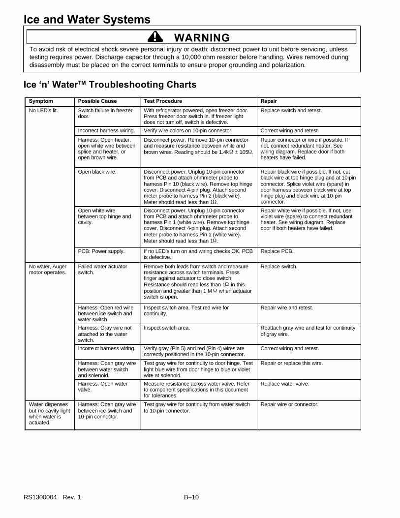
RS1300004 Rev. 1 B–10
Ice ‘n’ WaterTM Troubleshooting Charts
Ice and Water Systems
! WARNINGTo avoid risk of electrical shock severe personal injury or death; disconnect power to unit before servicing, unlesstesting requires power. Discharge capacitor through a 10,000 ohm resistor before handling. Wires removed duringdisassembly must be placed on the correct terminals to ensure proper grounding and polarization.
Symptom Possible Cause Test Procedure Repair
Switch failure in freezer door.
With refrigerator powered, open freezer door. Press freezer door switch in. If freezer light does not turn off, switch is defective.
Replace switch and retest.
Incorrect harness wiring. Verify wire colors on 10-pin connector. Correct wiring and retest.
Harness: Open heater, open white wire between splice and heater, or open brown wire.
Disconnect power. Remove 10-pin connector and measure resistance between white and brown wires. Reading should be 1.4kΩ ± 105Ω.
Repair connector or wire if possible. If not, connect redundant heater. See wiring diagram. Replace door if both heaters have failed.
Open black wire. Disconnect power. Unplug 10-pin connector from PCB and attach ohmmeter probe to harness Pin 10 (black wire). Remove top hinge cover. Disconnect 4-pin plug. Attach second meter probe to harness Pin 2 (black wire). Meter should read less than 1Ω.
Repair black wire if possible. If not, cut black wire at top hinge plug and at 10-pin connector. Splice violet wire (spare) in door harness between black wire at top hinge plug and black wire at 10-pin connector.
Open white wire between top hinge and cavity.
Disconnect power. Unplug 10-pin connector from PCB and attach ohmmeter probe to harness Pin 1 (white wire). Remove top hinge cover. Disconnect 4-pin plug. Attach second meter probe to harness Pin 1 (white wire). Meter should read less than 1Ω.
Repair white wire if possible. If not, use violet wire (spare) to connect redundant heater. See wiring diagram. Replace door if both heaters have failed.
No LED’s lit.
PCB: Power supply. If no LED’s turn on and wiring checks OK, PCB is defective.
Replace PCB.
Failed water actuator switch.
Remove both leads from switch and measure resistance across switch terminals. Press finger against actuator to close switch. Resistance should read less than 1Ω in this position and greater than 1 M Ω when actuator switch is open.
Replace switch.
Harness: Open red wire between ice switch and water switch.
Inspect switch area. Test red wire for continuity.
Repair wire and retest.
Harness: Gray wire not attached to the water switch.
Inspect switch area. Reattach gray wire and test for continuity of gray wire.
Incorre ct harness wiring. Verify gray (Pin 5) and red (Pin 4) wires are correctly positioned in the 10-pin connector.
Correct wiring and retest.
Harness: Open gray wire between water switch and solenoid.
Test gray wire for continuity to door hinge. Test light blue wire from door hinge to blue or violet wire at solenoid.
Repair or replace this wire.
No water, Auger motor operates.
Harness: Open water valve.
Measure resistance across water valve. Refer to component specifications in this document for tolerances.
Replace water valve.
Water dispenses but no cavity light when water is actuated.
Harness: Open gray wire between ice switch and 10-pin connector.
Test gray wire for continuity from water switch to 10-pin connector.
Repair wire or connector.

B–11 RS1300004 Rev. 1
Ice and Water Systems
! WARNINGTo avoid risk of electrical shock severe personal injury or death; disconnect power to unit before servicing, unlesstesting requires power. Discharge capacitor through a 10,000 ohm resistor before handling. Wires removed duringdisassembly must be placed on the correct terminals to ensure proper grounding and polarization.
Symptom Possible Cause Test Procedure Repair
Incorrect harness wiring. Verify correct wiring of 10 -pin connector. Correct wiring and retest. No auger motor. Cavity light comes on when water is actuated but not when ice is actuated.
Harness: Open black/red wire between connector and auger switch.
Test black/red wire for continuity. Repair wire or replace door.
Operational error: Lock mode may be enabled.
Press and hold DISPENSER LOCK button for 4 seconds.
Customer education.
Harness: Open red wire in harness (Pin 4 on 10-pin connector) between connector and auger switch.
Disconnect power. Unplug 10-pin connector from PCB and attach ohmmeter probe to harness Pin 4 (red wire). Remove red wire from auger switch. Attach second ohmmeter probe to red wire. Look for less than 1Ω resistance.
Repair wire or terminal.
LED’s operate but no ice or water. Cavity light does not come on when ice or water is actuated. Night light works properly.
PCB: Lock relay stuck open.
Disconnect power. Remove 10 -pin connector from PCB. On PCB, measure resistance between Pin 10 and Pin 4. Meter should read less than 2Ω.
Replace PCB.
LED’s operate. Cavity light comes on when ice or water actuated, but no auger motor.
Auger motor: Open winding or connection.
Perform standard auger motor test. Replace auger motor.
No night light. Cavity light works properly.
PCB defective. Verify LED above AUTO LIGHT button is lit. Completely cover sensor lens with coin. If night-light turns on, then product is operating within spec. Otherwise, PCB needs replaced.
Replace PCB.
Bulb burnt out. Measure resistance across bulb filament. If higher than 1k Ω, replace bulb.
Replace bulb.
Harness: Open white wire between cavity light and splice in door. Wire not connected at light socket.
Inspect wire for proper connection at 10 -pin connector and cavity-light socket. Ohmmeter should show short between white wire at cavity light and neutral on the power cord.
Repair or replace white wire or connection, or splice in violet wire (spare) if white wire is not accessible.
Harness: Open white wire between 10-pin connector and cavity light.
Test white wire for continuity. Repair or replace white wire or terminal.
Harness: Yellow wire open or not connected between 10-pin connector and light socket.
Test yellow wire for continuity. Repair or replace yellow wire or attach wire to light socket.
Incorrect harness wiring. Check color-coding of wires against wiring diagram.
Correct wiring and retest.
No light at all. Everything else works properly.
PCB failure. If LED’s turn on, PCB is defective. Replace PCB. Switch failure: Shorted auger switch.
Remove both leads from switch. Measure resistance across switch terminals. Resistance is greater than 1MΩ in open position and less than 1Ω when switch is closed.
Replace auger switch. Ice all the time.
PCB failure. If LED’s turn on, PCB is defective. Replace PCB.

RS1300004 Rev. 1 B–12
Ice and Water Systems
! WARNINGTo avoid risk of electrical shock severe personal injury or death; disconnect power to unit before servicing, unlesstesting requires power. Discharge capacitor through a 10,000 ohm resistor before handling. Wires removed duringdisassembly must be placed on the correct terminals to ensure proper grounding and polarization.
Symptom Possible Cause Test Procedure Repair
Shorted water solenoidswitch.
Remove leads from switch and measureresistance across switch terminals. Resistanceis greater than 1M Ω in open position and lessthan 1Ω when actuator is pressed closed.
Replace water solenoid switch.
PCB failure. If no LED’s turn on PCB is defective. Replace PCB.
Water all the time.
Water valve stuck open. Remove power to the refrigerator. If water stillflows through the valve, valve is bad or there islow water pressure.
Replace the water valve or correcthousehold water pressure.
Operational error: Lensis dirty or covered withcontamination.
Make sure nothing covers or masksphotosensitive lens.
Clean lens area of control.Night-light on allthe time. Cavitylight worksproperly, comes onwhen ice or wateractuated.
PCB: Defective photo-sensor circuit.
If night-light is on all the time and procedureabove has been preformed, PCB is defective.
Replace PCB.
Cavity light all thetime. Ice and waterwork OK.
Incorrect harness wiring. Verify wire colors on 10-pin connector againstthe wiring diagram.
Correct wiring and retest.
Filter LED neverchanges to red.
Operational error: Usermistakenly resets filtercounter.
Demonstrate reset operation to customer. Customer education.
Redundant Heater Wiring
10-pinConnector
Pin-1
Pin-3
BLK/WH
WH WH
BLK/WHBRN
This is how wiring should look at the 10-pinconnector after redundant heater is wiredinto system per Instruction 1.
Instruction 1: Instruction 1: Wire in redundant heater when heater-circuit failure occurs betweenheater splice and dispenser cavity (See Wiring Diagram). Cut white wire two inchesaway from 10-pin connector. Splice one of the Blk/Wh leads from wire harness toloose ends of the white wire. Next, cut the brown wire two inches from the 10-pinconnector. Splice the other Blk/Wh wire to the two-inch stub of the brown wire atPin 3 of the 10-pin connector. Tape off the remaining, loose end of the brown wire.
NOTE: NOTE: Never wire in both heaters at the same time. Doing so will ruin the PCB.

B–13 RS1300004 Rev. 1
Ice and Water Systems
! WARNINGTo avoid risk of electrical shock severe personal injury or death; disconnect power to unit before servicing, unlesstesting requires power. Discharge capacitor through a 10,000 ohm resistor before handling. Wires removed duringdisassembly must be placed on the correct terminals to ensure proper grounding and polarization.
All Ice & Water Systems
Seconds to dispense 10 oz. waterSupply pressure 20 psig* 30 psig* 40 psig* 50 psig* 60 psig* 70 psig*
Filter model,bypass installed 18.1 14.3 12.2 10.8 9.8 9.0
Filter model, newfilter installed
22.0 17.3 14.2 12.8 11.5 10.4
*Amana specifies a minimum supply pressure of 35 psig for water filter units. Minimum pressure requirementensures that water valves close and sufficient water volume is available to fill icemaker. Proper fill is 140 cc.of water in 7.5 seconds. Failure of water valves to close because of low pressure will result in fill-tube freeze-upor dripping at cavity.
This is how wiring should look at the 10-pinconnector after redundant heater is wiredinto system per Instruction 2.
10-pinConnector
Pin 1
Pin 3
BLK/WH
WH WH
BLK/WHBRN
VT
Instruction 2: Instruction 2: Wire in redundant heater when heater-circuit failure occurs in whitewire between top hinge and heater splice (See Wiring Diagram). Cut white wiretwo inches from 4-pin connector at top hinge. Splice violet wire onto two-inch stubof white wire at 4-pin connector. Tape off remaining, loose end of white wire.In cavity, cut white wire two inches from 10-pin connector. Splice violet wire andone Blk/Wh wire to two-inch stub of white wire at 10-pin connector. Tape off looseend of white wire. Next, cut brown wire two inches from Pin 3 on 10-pin connector.Splice second Blk/Wh wire to two-inch stub of Brown wire at 10-pin connector.Tape off loose end of brown wire.
NOTE:NOTE: Never wire in both heaters at the same time. Doing so will ruin the PCB.

RS1300004 Rev. 1 B–14
“Filter” model SxSwater flow diagram
Water Temperature Chart (Approximate)
0
10
20
30
40
50
60
70
1 2 3 4 5
Number of 8-ounce Glasses of WaterWater temperature has stabilized for at least 12 hours in water reservoir
Fresh food compartment temperature is 38–40 degrees Fahrenheit
Tem
per
atu
re in
Fah
ren
hei
t
90o AmbientNormalized 39o
64o AmbientNormalized 39o
Icemaker
Ice fill tube
.1/4" O.Dplastic tubing
Water filter inlet
Water filter outlet
Primary solenoidvalve icemaker coil(brown)
Household waterline connection1/4" O.D.copper tubecompression fitting
Ice & waterdispenser
Primary solenoidvalve waterdispenser coil(purple)
Secondarysolenoidvalve inlet
Secondarysolenoidvalve waterdispenser coil(purple)
1/4" O.D. x 5/16" O.D.plastic compressionunion fitting Secondary solenoid
valve icemaker coil(brown)
Water tank
Ice and Water Systems

C-1 RS1300004 Rev. 1
Appendix C

RS1300004 Rev. 1 C-2
This refrigerator operates most efficiently when it isproperly installed. Amana cannot be responsible for loss,injury or damage caused by improper installation orunqualified personnel.
Unpack Unit1. Cut wire bands at top and bottom of refrigerator
carton and remove carton lid.2. Use a razor knife to slit down side of carton on dotted
line, being careful not to gouge the machine.3. Peel carton off unit and lay carton aside.4. Tape doors shut to prevent damage caused by
unexpected opening.
CAUTION!To avoid property damage or personal injury, twoperson lift is required to remove appliance skid.
5. Remove styrofoam pads from top of refrigerator andplace them on floor behind unit so that, whenrefrigerator is tipped over backward, one padsupports unit just above machine compartment andother pad supports unit near its top.
NOTE: Machine compartment cover will not bear theweight of the unit. Styrofoam pad must belocated ABOVE machine compartment cover.
6. Gently tip unit backward until it lies on styrofoampads as described in Step 5.
NOTE: Do not leave refrigerator lying on its back longerthan necessary.
7. Pull bottom of carton off appliance skid. Remove allmounting bolts from appliance skid. Remove skidfrom unit and discard skid.
8. Gently return refrigerator to upright position.
WARNING!To avoid electrical shock, severe personal injury ordeath; disconnect power to unit before removingdoors.
Installation InstructionsNOTE: On models covered by this manual, doors are
foamed as assemblies at factory. Inner doorliners and outer door pans are not replaceable.If either is damaged, door must be replaced.
Refrigerator Door (Electronic)1. Open door and remove storage buckets.2. Remove toe grille.
• Grip grille firmly at both ends.• Pull straight out, away from unit.
3. Disconnect wiring harness from high-voltage (HV)box behind toe grille.
High-Voltage Box
4. Remove screw that mounts door closure to bottomhinge.
Doorclosure
Screw
BottomHinge Pin
Bottom Hinge Pin & Door Closure(door removed for clarity)
5. Close door.6. On decorator units, remove screws that hold trim
strip to top of door and remove trim strip.7. Remove screw that holds cover on top hinge and
remove hinge cover.8. Unplug wiring harness; remove ground screw and
ground wire from hinge.

C-3 RS1300004 Rev. 1
Refrigerator Door (Nonelectronic)1. Open door and remove storage buckets.2. Remove screw that mounts door closure to bottom
hinge.3. Close door.4. On decorator units, remove screws that hold trim
strip to top of door and remove trim strip.5. Remove screw that holds cover on top hinge and
remove hinge cover.
CAUTION!To avoid personal injury or property damage, due todoor falling, Secure door to cabinet with strappingtape before top hinge is removed.
6. Remove three mounting screws from top hinge.Remove top hinge and hinge bushing.
NOTE: Hinge shim adheres to top of cabinet andshould be left in place. Shim helps to properlylocate top hinge when rehanging the door.
7. Open door carefully and lift about 3 inches to bringlower hinge bushing up, off hinge pin.
8. Set bottom edge of door on protective pad. Removehinge pin (with door-closure tab) from bottom hingebracket.
9. If situation requires that unit be as “thin” as possible,remove mounting bolts from bottom hinge bracketand remove bottom hinge bracket.
10.Lay door aside on protective mat.
Freezer Door (Dispenser)1. Open door and remove all storage buckets.2. Remove toe grille.3. Loosen water-tube clamp screw. Loosen plastic
water-tube union nut. Pull water tube away fromunion nut and through tube clamp.
Clamp Screw
Union NutFreezer DoorBottom Hinge
Water Tube
4. Remove screw that mounts door closure to topsurface of bottom hinge.
5. Close door.
CAUTION!To avoid personal injury or property damage, due todoor falling, Secure door to cabinet with strappingtape before top hinge is removed.
Wire Connectors HingeCap
Hinge
HingeShim
Electronicand Dispenser Doors All Doors
HingeBushing
Top Hinge Nomenclature,Side-by-Side Refrigerator & Freezer Doors
Ground Wire
9. Remove mounting screws from top hinge. Removetop hinge and hinge bushing and carefully pull themoff wiring harness.
NOTE: Hinge shim adheres to top of cabinet andshould be left in place. Shim helps to properlylocate top hinge when rehanging the door.
10.Open door carefully and lift about 3 inches to bringlower hinge bushing up, off hinge pin.
11. Set bottom edge of door on protective pad. Removehinge pin (with door-closure tab) and wiring harnessfrom bottom hinge bracket.
12. If situation requires that unit be as “thin” as possible,remove mounting bolts from bottom hinge bracketand remove bottom hinge bracket.
13.Lay door aside on protective mat.
Installation Instructions

RS1300004 Rev. 1 C-4
6. Remove screw holding top hinge cover in place andremove hinge cover.
7. Unplug wiring harness connectors. Remove groundscrew and ground wire from top hinge.
CAUTION!To avoid personal injury or property damage, due todoor falling, Secure door to cabinet with strappingtape before top hinge is removed.
8. Remove top hinge and hinge bushing. Pull hinge andbushing off wiring harness.
NOTE: Hinge shim adheres to top of cabinet andshould be left in place. Shim helps to properlylocate top hinge when rehanging the door.
9. Lift door about 3 inches to bring lower hinge bushingup, off hinge pin.
10. Set bottom edge of door on protective pad. Removehinge pin (with door-closure tab and water tube) frombottom hinge bracket.
11. If situation requires that unit be as “thin” as possible,remove mounting bolts from bottom hinge bracketand remove bottom hinge bracket.
13. Lay door aside on protective mat.
Freezer Door (No Dispenser)1. Open door and remove all storage buckets.2. Remove toe grille.3. Remove screw that mounts door closure to bottom
hinge.
Doorclosure
Screw
BottomHinge Pin
4. Close door.
5. Remove screw holding top hinge cover in place andremove hinge cover.
CAUTION!To avoid personal injury or property damage, due todoor falling, Secure door to cabinet with strappingtape before top hinge is removed.
6. Remove three mounting screws from top hinge.Remove top hinge and hinge bushing.
NOTE: Hinge shim adheres to top of cabinet andshould be left in place. Shim helps to properlylocate top hinge when rehanging the door.
7. Lift door about 3 inches to bring lower hinge bushingup, off hinge pin.
8. Set bottom edge of door on protective pad. Removehinge pin (with door-closure tab) from bottom hingebracket.
9. If situation requires that unit be as “thin” as possible,remove mounting bolts from bottom hinge bracketand remove bottom hinge bracket.
10. Lay door aside on protective mat.
Moving Unit1. Remove doors if necessary.2. Slide appliance cart under side of unit. Wrap
refrigerator carefully with blanket or appliance pad.Thread cart strap around refrigerator and tighten.
CAUTION!To avoid personal injury or property damage, protectflooring with cardboard or other protective materialwhen moving unit.
3. Move refrigerator in front of final location and rehangdoors by reversing removal procedure.
NOTE: Do not tighten top hinge screws or replace toegrille at this time.
If unit has an ice maker, proceed with Water Supply. Ifunit has no ice maker, skip to Final Steps.
Installation Instructions

C-5 RS1300004 Rev. 1
Water Supply
WARNING!To avoid electrical shock, severe personal injury ordeath; disconnect power to unit before connectingwater supply line.
1. Connect water supply.a. Get a licensed plumber to connect shut-off valve
and water-supply tube to household plumbing incompliance with local codes.
NOTE: Use only seamless, flexible, 1/4" (6 mm) coppertubing. Tubing must be long enough to reachfrom water supply to refrigerator connection plusan additional 8' (2.4 M) with which to formservice loop behind refrigerator.
NOTE: The correct type of shut-off valve requires that a1/4" (6 mm) hole be drilled in the householdwater pipe before the valve is attached. Do notuse a self-piercing shut-off valve or a valve ofany size other than 1/4" (6 mm). Amana is notresponsible for property damage caused byimproper water connection.
CAUTION!To avoid risk of property damage, supply towels tosoak up any spillage of water.
b. Confirm that water pressure at refrigerator end ofwater-supply line is between 20 psi and 100 psi(between 1.4 and 7.0 kg/cm2).
NOTE: Units with filter require pressure between 35 psiand 100 psi (2.5 and 7.0 kg/cm2).
NOTE: Water valves in your refrigerator will not workproperly if system pressure is not within spec.
c. Remove plastic cap from water-valve inlet port onback of refrigerator. Place brass nut and brassferrule on copper water-supply tube.
Brass Ferrule
1/4" Copper Tubing
ThreadedWater-Valve Inlet
Brass Nut
Refrigerator
Water Supply
d. Slide water-supply tube into water-valve inlet port.Slide ferrule and nut down to inlet port. Start nutonto threaded inlet port. Turn nut down finger tightand finish with a spanner.
2. Confirm that connection is secure by pulling oncopper tubing.
3. Turn on water supply valve at household plumbingand check system for leaks.
4. Use slack in tubing to form service loop behindrefrigerator taking care, as you do so, not to kinkthe tubing.
Final Steps1. Plug in power cord.2. Move refrigerator into final location.3. Level refrigerator and align doors.
a. At bottom of unit, in front: Turn roller-adjustmentscrews as necessary to raise or lower corners ofcabinet until unit is level and stable.
Front RollerAdjustment Screw
Rear RollerAdjustment Screw
Roller
b. At top of unit, door corners at center of unit shouldbe about 1/8" (3 mm) higher than door corners athinges. Doors will sag level when loaded withfood.
c. Lay a dime on door gaskets. Use dime to spacerefrigerator and freezer doors 11/16" (18 mm)from edge of cabinet.
d. Tighten all hinge screws.4. Install toe grille by snapping it into place.
Installation Instructions