rsa5100a series real-time signal analyzer service manual
TRANSCRIPT

xx
RSA5100A SeriesReal-Time Signal Analyzer
ZZZ
Service Manual
*P077052201*
077-0522-01

RSA5100A SeriesReal-Time Signal Analyzer
ZZZ
Service Manual
xx
www.tektronix.com077-0522-01
Copyright © Tektronix. All rights reserved. Licensed software products are owned by Tektronix or its subsidiariesor suppliers, and are protected by national copyright laws and international treaty provisions.
Tektronix products are covered by U.S. and foreign patents, issued and pending. Information in this publicationsupersedes that in all previously published material. Specifications and price change privileges reserved.
TEKTRONIX and TEK are registered trademarks of Tektronix, Inc.
Contacting Tektronix
Tektronix, Inc.14150 SW Karl Braun DriveP.O. Box 500Beaverton, OR 97077USA
For product information, sales, service, and technical support:In North America, call 1-800-833-9200.Worldwide, visit www.tektronix.com to find contacts in your area.

Table of Contents
General safety summary .. . . . . . . . . . . . . . . . . . . . . . . . . . . . . . . . . . . . . . . . . . . . . . . . . . . . . . . . . . . . . . . . . . . . . . . . . . . . . . . . . . . . . . . . . iv
Service safety summary. . . . . . . . . . . . . . . . . . . . . . . . . . . . . . . . . . . . . . . . . . . . . . . . . . . . . . . . . . . . . . . . . . . . . . . . . . . . . . . . . . . . . . . . . . . vi
Preface .. . . . . . . . . . . . . . . . . . . . . . . . . . . . . . . . . . . . . . . . . . . . . . . . . . . . . . . . . . . . . . . . . . . . . . . . . . . . . . . . . . . . . . . . . . . . . . . . . . . . . . . . . . . . vii
Manual Content . . . . . . . . . . . . . . . . . . . . . . . . . . . . . . . . . . . . . . . . . . . . . . . . . . . . . . . . . . . . . . . . . . . . . . . . . . . . . . . . . . . . . . . . . . . . . . vii
Manual Conventions. . . . . . . . . . . . . . . . . . . . . . . . . . . . . . . . . . . . . . . . . . . . . . . . . . . . . . . . . . . . . . . . . . . . . . . . . . . . . . . . . . . . . . . . . vii
Related User Documents. . . . . . . . . . . . . . . . . . . . . . . . . . . . . . . . . . . . . . . . . . . . . . . . . . . . . . . . . . . . . . . . . . . . . . . . . . . . . . . . . . . . viii
Operating Information .. . . . . . . . . . . . . . . . . . . . . . . . . . . . . . . . . . . . . . . . . . . . . . . . . . . . . . . . . . . . . . . . . . . . . . . . . . . . . . . . . . . . . . . . . . . . 1
Theory of Operation. . . . . . . . . . . . . . . . . . . . . . . . . . . . . . . . . . . . . . . . . . . . . . . . . . . . . . . . . . . . . . . . . . . . . . . . . . . . . . . . . . . . . . . . . . . . . . . . 3
General. . . . . . . . . . . . . . . . . . . . . . . . . . . . . . . . . . . . . . . . . . . . . . . . . . . . . . . . . . . . . . . . . . . . . . . . . . . . . . . . . . . . . . . . . . . . . . . . . . . . . . . . . . 4
Signal Path and Processing .. . . . . . . . . . . . . . . . . . . . . . . . . . . . . . . . . . . . . . . . . . . . . . . . . . . . . . . . . . . . . . . . . . . . . . . . . . . . . . . . . . 4
Display Panel. . . . . . . . . . . . . . . . . . . . . . . . . . . . . . . . . . . . . . . . . . . . . . . . . . . . . . . . . . . . . . . . . . . . . . . . . . . . . . . . . . . . . . . . . . . . . . . . . . . 5
Front Panel . . . . . . . . . . . . . . . . . . . . . . . . . . . . . . . . . . . . . . . . . . . . . . . . . . . . . . . . . . . . . . . . . . . . . . . . . . . . . . . . . . . . . . . . . . . . . . . . . . . . . 5
Rear Panel . . . . . . . . . . . . . . . . . . . . . . . . . . . . . . . . . . . . . . . . . . . . . . . . . . . . . . . . . . . . . . . . . . . . . . . . . . . . . . . . . . . . . . . . . . . . . . . . . . . . . . 5
Power Supply.. . . . . . . . . . . . . . . . . . . . . . . . . . . . . . . . . . . . . . . . . . . . . . . . . . . . . . . . . . . . . . . . . . . . . . . . . . . . . . . . . . . . . . . . . . . . . . . . . . 6
Fans. . . . . . . . . . . . . . . . . . . . . . . . . . . . . . . . . . . . . . . . . . . . . . . . . . . . . . . . . . . . . . . . . . . . . . . . . . . . . . . . . . . . . . . . . . . . . . . . . . . . . . . . . . . . . . 6
Adjustment Procedure. . . . . . . . . . . . . . . . . . . . . . . . . . . . . . . . . . . . . . . . . . . . . . . . . . . . . . . . . . . . . . . . . . . . . . . . . . . . . . . . . . . . . . . . . . . . . . 7
Running Alignments. . . . . . . . . . . . . . . . . . . . . . . . . . . . . . . . . . . . . . . . . . . . . . . . . . . . . . . . . . . . . . . . . . . . . . . . . . . . . . . . . . . . . . . . . . . 7
Maintenance.. . . . . . . . . . . . . . . . . . . . . . . . . . . . . . . . . . . . . . . . . . . . . . . . . . . . . . . . . . . . . . . . . . . . . . . . . . . . . . . . . . . . . . . . . . . . . . . . . . . . . . . . 9
Preventing ESD ... . . . . . . . . . . . . . . . . . . . . . . . . . . . . . . . . . . . . . . . . . . . . . . . . . . . . . . . . . . . . . . . . . . . . . . . . . . . . . . . . . . . . . . . . . . . . . 9
Inspection and Cleaning.. . . . . . . . . . . . . . . . . . . . . . . . . . . . . . . . . . . . . . . . . . . . . . . . . . . . . . . . . . . . . . . . . . . . . . . . . . . . . . . . . . . . . 10
Restoring the Instrument Software . . . . . . . . . . . . . . . . . . . . . . . . . . . . . . . . . . . . . . . . . . . . . . . . . . . . . . . . . . . . . . . . . . . . . . . . . . . . . . 13
Restore the Microsoft Windows 7 Operating System.. . . . . . . . . . . . . . . . . . . . . . . . . . . . . . . . . . . . . . . . . . . . . . . . . . . . 13
Restoring the Instrument Product Software. . . . . . . . . . . . . . . . . . . . . . . . . . . . . . . . . . . . . . . . . . . . . . . . . . . . . . . . . . . . . . . . 16
Get the Latest Software . . . . . . . . . . . . . . . . . . . . . . . . . . . . . . . . . . . . . . . . . . . . . . . . . . . . . . . . . . . . . . . . . . . . . . . . . . . . . . . . . . . . . . 16
Removal and Installation Procedures. . . . . . . . . . . . . . . . . . . . . . . . . . . . . . . . . . . . . . . . . . . . . . . . . . . . . . . . . . . . . . . . . . . . . . . . . . . . 17
Preparation. . . . . . . . . . . . . . . . . . . . . . . . . . . . . . . . . . . . . . . . . . . . . . . . . . . . . . . . . . . . . . . . . . . . . . . . . . . . . . . . . . . . . . . . . . . . . . . . . . . . . 17
Trim, Cabinet, and Module Removal . . . . . . . . . . . . . . . . . . . . . . . . . . . . . . . . . . . . . . . . . . . . . . . . . . . . . . . . . . . . . . . . . . . . . . . 19
Removal Procedures. . . . . . . . . . . . . . . . . . . . . . . . . . . . . . . . . . . . . . . . . . . . . . . . . . . . . . . . . . . . . . . . . . . . . . . . . . . . . . . . . . . . . . . . . . 22
Troubleshooting.. . . . . . . . . . . . . . . . . . . . . . . . . . . . . . . . . . . . . . . . . . . . . . . . . . . . . . . . . . . . . . . . . . . . . . . . . . . . . . . . . . . . . . . . . . . . . . . . . . . 26
Service Level . . . . . . . . . . . . . . . . . . . . . . . . . . . . . . . . . . . . . . . . . . . . . . . . . . . . . . . . . . . . . . . . . . . . . . . . . . . . . . . . . . . . . . . . . . . . . . . . . . 27
Check for Common Problems . . . . . . . . . . . . . . . . . . . . . . . . . . . . . . . . . . . . . . . . . . . . . . . . . . . . . . . . . . . . . . . . . . . . . . . . . . . . . . . 27
Diagnostics . . . . . . . . . . . . . . . . . . . . . . . . . . . . . . . . . . . . . . . . . . . . . . . . . . . . . . . . . . . . . . . . . . . . . . . . . . . . . . . . . . . . . . . . . . . . . . . . . . . . 29
Replaceable Parts . . . . . . . . . . . . . . . . . . . . . . . . . . . . . . . . . . . . . . . . . . . . . . . . . . . . . . . . . . . . . . . . . . . . . . . . . . . . . . . . . . . . . . . . . . . . . . . . . . 45
Parts Ordering Information .. . . . . . . . . . . . . . . . . . . . . . . . . . . . . . . . . . . . . . . . . . . . . . . . . . . . . . . . . . . . . . . . . . . . . . . . . . . . . . . . . 45
Using the Replaceable Parts List . . . . . . . . . . . . . . . . . . . . . . . . . . . . . . . . . . . . . . . . . . . . . . . . . . . . . . . . . . . . . . . . . . . . . . . . . . . . 46
RSA5100A Series Service Manual i
Table of Contents
List of Figures
Figure 1: RSA5100A Series block diagram .. . . . . . . . . . . . . . . . . . . . . . . . . . . . . . . . . . . . . . . . . . . . . . . . . . . . . . . . . . . . . . . . . . . . 3
Figure 2: Power supply and HDD/DVD drive locations . . . . . . . . . . . . . . . . . . . . . . . . . . . . . . . . . . . . . . . . . . . . . . . . . . . . . . 20
Figure 3: Main customer replaceable modules. . . . . . . . . . . . . . . . . . . . . . . . . . . . . . . . . . . . . . . . . . . . . . . . . . . . . . . . . . . . . . . . . 21
Figure 4: Status indicator locations. . . . . . . . . . . . . . . . . . . . . . . . . . . . . . . . . . . . . . . . . . . . . . . . . . . . . . . . . . . . . . . . . . . . . . . . . . . . . . 28
Figure 5: External parts . . . . . . . . . . . . . . . . . . . . . . . . . . . . . . . . . . . . . . . . . . . . . . . . . . . . . . . . . . . . . . . . . . . . . . . . . . . . . . . . . . . . . . . . . . . 48
Figure 6: Display, front panel, DVD, and removable hard drive. . . . . . . . . . . . . . . . . . . . . . . . . . . . . . . . . . . . . . . . . . . . . 50
Figure 7: Modules . . . . . . . . . . . . . . . . . . . . . . . . . . . . . . . . . . . . . . . . . . . . . . . . . . . . . . . . . . . . . . . . . . . . . . . . . . . . . . . . . . . . . . . . . . . . . . . . . 52
Figure 8: Power supply and internal hard drive . . . . . . . . . . . . . . . . . . . . . . . . . . . . . . . . . . . . . . . . . . . . . . . . . . . . . . . . . . . . . . . . 54
Figure 9: Upper deck fans, misc. cables . . . . . . . . . . . . . . . . . . . . . . . . . . . . . . . . . . . . . . . . . . . . . . . . . . . . . . . . . . . . . . . . . . . . . . . . 56
ii RSA5100A Series Service Manual

Table of Contents
List of Tables
Table 1: Rear panel connectors . . . . . . . . . . . . . . . . . . . . . . . . . . . . . . . . . . . . . . . . . . . . . . . . . . . . . . . . . . . . . . . . . . . . . . . . . . . . . . . . . . . 5
Table 2: External inspection checklist. . . . . . . . . . . . . . . . . . . . . . . . . . . . . . . . . . . . . . . . . . . . . . . . . . . . . . . . . . . . . . . . . . . . . . . . . . . 11
Table 3: Internal inspection check list. . . . . . . . . . . . . . . . . . . . . . . . . . . . . . . . . . . . . . . . . . . . . . . . . . . . . . . . . . . . . . . . . . . . . . . . . . . 12
Table 4: Tools required for module removal . . . . . . . . . . . . . . . . . . . . . . . . . . . . . . . . . . . . . . . . . . . . . . . . . . . . . . . . . . . . . . . . . . . 18
Table 5: Legend for accessing modules table . . . . . . . . . . . . . . . . . . . . . . . . . . . . . . . . . . . . . . . . . . . . . . . . . . . . . . . . . . . . . . . . . . 19
Table 6: Accessing modules. . . . . . . . . . . . . . . . . . . . . . . . . . . . . . . . . . . . . . . . . . . . . . . . . . . . . . . . . . . . . . . . . . . . . . . . . . . . . . . . . . . . . . 19
Table 7: Failure symptoms and possible causes. . . . . . . . . . . . . . . . . . . . . . . . . . . . . . . . . . . . . . . . . . . . . . . . . . . . . . . . . . . . . . . . 27
Table 8: Power Converter board LED status indicators . . . . . . . . . . . . . . . . . . . . . . . . . . . . . . . . . . . . . . . . . . . . . . . . . . . . . . . 29
Table 9: Digital Interface board LED status indicators. . . . . . . . . . . . . . . . . . . . . . . . . . . . . . . . . . . . . . . . . . . . . . . . . . . . . . . . 29
Table 10: Hardware module diagnostic error messages. . . . . . . . . . . . . . . . . . . . . . . . . . . . . . . . . . . . . . . . . . . . . . . . . . . . . . . 35
Table 11: Digital Interface Board diagnostic error messages. . . . . . . . . . . . . . . . . . . . . . . . . . . . . . . . . . . . . . . . . . . . . . . . . 35
Table 12: ADC Board diagnostic error messages . . . . . . . . . . . . . . . . . . . . . . . . . . . . . . . . . . . . . . . . . . . . . . . . . . . . . . . . . . . . . . 36
Table 13: DPSA Board diagnostic error messages . . . . . . . . . . . . . . . . . . . . . . . . . . . . . . . . . . . . . . . . . . . . . . . . . . . . . . . . . . . . 37
Table 14: RF Interface Board diagnostic error messages . . . . . . . . . . . . . . . . . . . . . . . . . . . . . . . . . . . . . . . . . . . . . . . . . . . . . 38
Table 15: LO1 Module diagnostic error messages. . . . . . . . . . . . . . . . . . . . . . . . . . . . . . . . . . . . . . . . . . . . . . . . . . . . . . . . . . . . . 39
Table 16: LO2/Reference Oscillator diagnostic error messages. . . . . . . . . . . . . . . . . . . . . . . . . . . . . . . . . . . . . . . . . . . . . . 40
Table 17: Front Panel diagnostic error messages . . . . . . . . . . . . . . . . . . . . . . . . . . . . . . . . . . . . . . . . . . . . . . . . . . . . . . . . . . . . . . 43
Table 18: External parts. . . . . . . . . . . . . . . . . . . . . . . . . . . . . . . . . . . . . . . . . . . . . . . . . . . . . . . . . . . . . . . . . . . . . . . . . . . . . . . . . . . . . . . . . . . 47
Table 19: Display, front panel, DVD, and removable hard drive . . . . . . . . . . . . . . . . . . . . . . . . . . . . . . . . . . . . . . . . . . . . 49
Table 20: Modules. . . . . . . . . . . . . . . . . . . . . . . . . . . . . . . . . . . . . . . . . . . . . . . . . . . . . . . . . . . . . . . . . . . . . . . . . . . . . . . . . . . . . . . . . . . . . . . . . 51
Table 21: Power supply and internal hard drive. . . . . . . . . . . . . . . . . . . . . . . . . . . . . . . . . . . . . . . . . . . . . . . . . . . . . . . . . . . . . . . . 53
Table 22: Upper deck fans, misc. cables. . . . . . . . . . . . . . . . . . . . . . . . . . . . . . . . . . . . . . . . . . . . . . . . . . . . . . . . . . . . . . . . . . . . . . . . 55
RSA5100A Series Service Manual iii

General safety summary
General safety summaryReview the following safety precautions to avoid injury and prevent damage tothis product or any products connected to it.
To avoid potential hazards, use this product only as specified.
Only qualified personnel should perform service procedures.
While using this product, you may need to access other parts of a larger system.Read the safety sections of the other component manuals for warnings andcautions related to operating the system.
To avoid fire or personalinjury
Use proper power cord. Use only the power cord specified for this product andcertified for the country of use.
Ground the product. This product is grounded through the grounding conductorof the power cord. To avoid electric shock, the grounding conductor must beconnected to earth ground. Before making connections to the input or outputterminals of the product, ensure that the product is properly grounded.
Observe all terminal ratings. To avoid fire or shock hazard, observe all ratingsand markings on the product. Consult the product manual for further ratingsinformation before making connections to the product.
The inputs are not rated for connection to mains or Category II, III, or IV circuits.
Power disconnect. The power cord disconnects the product from the power source.Do not block the power cord; it must remain accessible to the user at all times.
Do not operate without covers. Do not operate this product with covers or panelsremoved.
Do not operate with suspected failures. If you suspect that there is damage to thisproduct, have it inspected by qualified service personnel.
Avoid exposed circuitry. Do not touch exposed connections and components whenpower is present.
Replace batteries properly. Replace batteries only with the specified type andrating.
Use proper fuse. Use only the fuse type and rating specified for this product.
Wear eye protection. Wear eye protection if exposure to high-intensity rays orlaser radiation exists.
iv RSA5100A Series Service Manual

General safety summary
Do not operate in wet/damp conditions.
Do not operate in an explosive atmosphere.
Keep product surfaces clean and dry.
Provide proper ventilation. Refer to the manual's installation instructions for detailson installing the product so it has proper ventilation.
Terms in this manual These terms may appear in this manual:
WARNING. Warning statements identify conditions or practices that could resultin injury or loss of life.
CAUTION. Caution statements identify conditions or practices that could result indamage to this product or other property.
Symbols and terms on theproduct
These terms may appear on the product:
DANGER indicates an injury hazard immediately accessible as you readthe marking.
WARNING indicates an injury hazard not immediately accessible as youread the marking.
CAUTION indicates a hazard to property including the product.
The following symbol(s) may appear on the product:
RSA5100A Series Service Manual v

Service safety summary
Service safety summaryOnly qualified personnel should perform service procedures. Read this Servicesafety summary and the General safety summary before performing any serviceprocedures.
Do not service alone. Do not perform internal service or adjustments of thisproduct unless another person capable of rendering first aid and resuscitation ispresent.
Disconnect power. To avoid electric shock, switch off the instrument power, thendisconnect the power cord from the mains power.
Use care when servicing with power on. Dangerous voltages or currents may existin this product. Disconnect power, remove battery (if applicable), and disconnecttest leads before removing protective panels, soldering, or replacing components.
To avoid electric shock, do not touch exposed connections.
vi RSA5100A Series Service Manual

PrefaceThis is the service manual for the RSA5100A Series Real-Time Signal Analyzers.
Read this preface to learn how this manual is structured, what conventions it uses,and where you can find other information related to servicing this product.
Manual ContentThis manual contains information related to servicing an RSA5100A SeriesReal-Time Signal Analyzer. For information related to installing and operatingthe instrument, or for a list of instrument specifications, refer to the appropriateuser document as described in Related User Documents on the following page.
Be sure to read the introductions to all procedures. These introductions provideimportant information needed to perform the service correctly, safely, andefficiently.
Manual ConventionsThis manual uses certain conventions that you should become familiar withbefore attempting service.
Module The term module refers to a collection of items that are replaceable as a unit. Amodule may contain electrical and mechanical assemblies, circuit boards, andinterconnecting cables.
Plug-In Module The term Plug-in Module refers to the units that plug into the Main DigitalInterface board.
Replaceable Parts This manual refers to any field-replaceable assembly or mechanical part by itsname or generically as a replaceable part. In general, a replaceable part is anycircuit board or assembly that is listed in the Replaceable Parts section.
Safety Symbols and terms related to safety appear in the General Safety Summary foundat the beginning of this manual. Be sure to read both the General Safety Summaryand Service Safety Summary before performing any service to this instrument.
RSA5100A Series Service Manual vii

Preface
Related User DocumentsThe following related English user documents are available if you need moreinformation about operating the instrument. These documents are located on theRSA5100A Series Real-Time Signal Analyzer User Documentation CD-ROM orcan be downloaded from the Tektronix Web site (www.tektronix.com/manuals).
RSA6100A Series Real-Time Spectrum Analyzers, RSA5100A Series Real-TimeSignal Analyzer Quick Start User Manual. This document provides the basicinformation you need to install and operate the instrument. The documentincludes a listing of the available instrument options and accessories.
RSA5100A Series Real-Time Signal Analyzer Series Specifications andPerformance Verification Technical Reference (English). This documentcontains the following technical information about the instrument:
Electrical and physical specifications, including a list of certificationsand compliances.
A performance verification procedure to check instrument performanceagainst guaranteed specifications.
RSA6100A Series Real-Time Spectrum Analyzers, RSA5100A SeriesReal-Time Signal Analyzer Programmer Manual (English). Describes theGPIB instrument programming commands and interface.
RSA5100A Series Real-Time Signal Analyzer Declassification and SecurityInstructions (English). Provides instruction on how customers with datasecurity concerns can sanitize or remove memory devices from the instrument.
viii RSA5100A Series Service Manual

Operating InformationFor information on installing and operating your RSA5100A Series Real-TimeSignal Analyzer, refer to the RSA6100A Series Real-Time Spectrum Analyzers,RSA5100A Series Real-Time Signal Analyzer Quick Start User Manual.
RSA5100A Series Service Manual 1

Operating Information
2 RSA5100A Series Service Manual
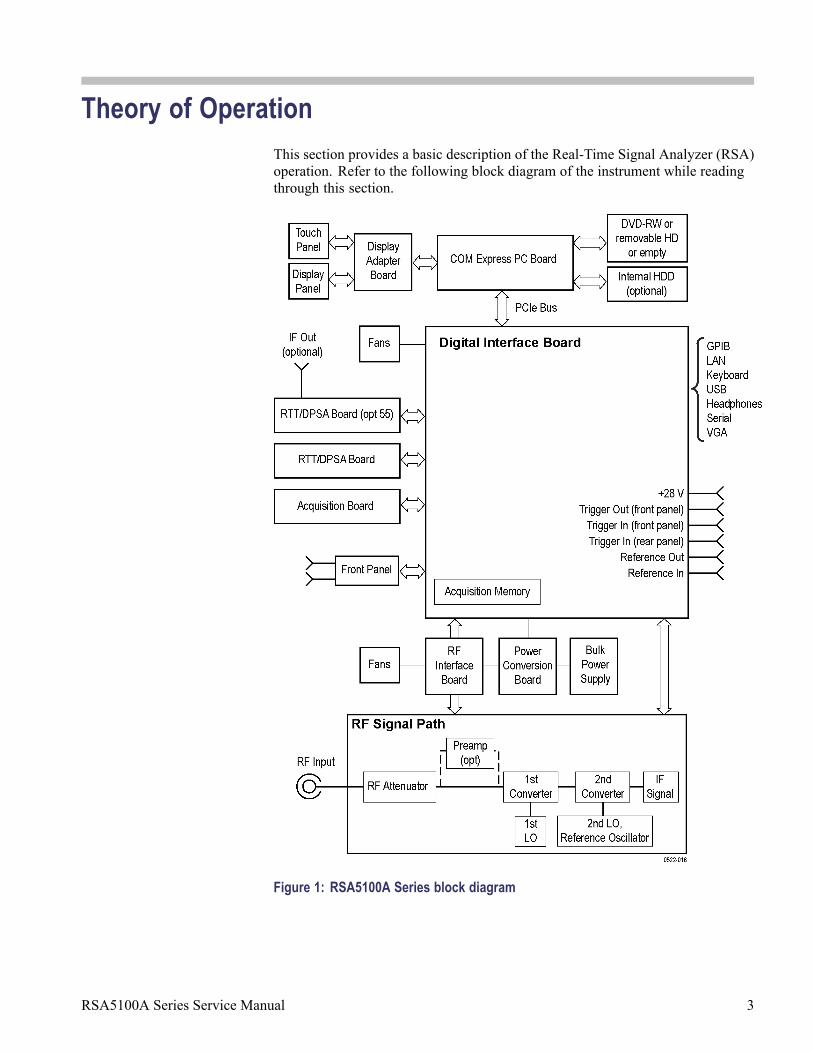
Theory of OperationThis section provides a basic description of the Real-Time Signal Analyzer (RSA)operation. Refer to the following block diagram of the instrument while readingthrough this section.
Figure 1: RSA5100A Series block diagram
RSA5100A Series Service Manual 3

Theory of Operation
GeneralA processor system controls the RSA5100A instrument. The instrument featuresan XGA resolution flat-panel display, a transparent touch-screen, and a front-panelwith direct access to common RSA features. You can also use the RSA with amouse or other pointing device, and/or a keyboard.
The RSA uses the Microsoft Windows 7 operating system.
Signal Path and ProcessingRF Signal Path An RF signal enters the RSA through a direct N-type coaxial connection.
The RF signal path consists of an attenuator, optional preamplifier, 1st converter,and 2nd converter. The purpose of the RF signal path is to translate a band-limitedreplica of a portion of the input signal range to an intermediate frequency (IF)which can be sampled by a high-dynamic-range A/D converter.
The processor system controls the RF signal path.
Acquisition System The acquisition system samples the IF signal and converts it to digital signals.These digital signals are then filtered numerically and processed either fordirect display or by measurement applications to provide signal quality metricsto the user. The acquisition data processing is performed by one of severalfield-programmable gate arrays (FPGAs) under control of the processor. Theprocessor performs measurement applications.
Processor System The processor system consists of a COM Express PCI-based processor board anda Digital Interface board that connects the processor to the acquisition board.
Trigger Inputs There are two coaxial trigger inputs. One is on the front panel below the displayand the other is on the rear panel. Both trigger inputs connect directly to theDigital Interface board. Trigger signals are processed by an FPGA on the DigitalInterface board. The information from the trigger system is combined withacquisition data by the processor system.
The Trigger Out signal is a coaxial connection on the front panel below thedisplay. The trigger out signal comes from the Acquisition Control FPGA,through the Digital Interface board.
4 RSA5100A Series Service Manual

Theory of Operation
Display PanelWaveforms, spectral traces, measurement results, and control menus are displayedon a 10.4 inch, color, active-matrix LCD display with touch panel.
Display System The display system consists of a display adapter board. The display adapter boardsends text and waveform information to the display panel.
Touch Panel The display adapter board sends information from the touch panel to the processor.The touch panel is listed as a USB HID device in the Window Device Managertool.
Front PanelThe processor system detects changes in the front-panel switches and encoder. Theprocessor also turns the LEDs on and off. Communication between the processorsystem and the front panel is performed over an internal USB connection.
The ON/STBY switch passes through the display adapter board, the PC carrierboard, the digital interface board, and to the PC board.
The DVD-RW and removable HDD (hard disk drive) communicate over a SATAconnection directly to the processor system.
Rear PanelThe following table describes the rear panel connectors.
Table 1: Rear panel connectors
NameInput orOutput
Connectortype Description
Reference In Input BNC External time-base reference. See datasheet for signal quality requirements.
ReferenceOut
Output BNC 10 MHz output or loop-through of userReference In signal
LAN Input/Output RJ-45 10/100/1000baseT Ethernet connector
USB Input/Output USB Two USB 2.0 connectors
Keyboard Input PS/2 Keyboard-only PS/2 connector
VGA Output D-Sub External monitor connector
Serial Input/Output D-Sub Serial communications port (COM1) toprocessor system
Trigger In Input BNC TTL Gate/trigger input signal
RSA5100A Series Service Manual 5

Theory of Operation
Table 1: Rear panel connectors (cont.)
NameInput orOutput
Connectortype Description
Line In (blue) Input 3.5 mmmono
Audio line input (disabled)
MIC In (pink) Input 3.5 mmmono
Audio input signal (microphone)
Headphone Output 3.5 mmstereo
External headphone connection
+28 VDC Output BNC Noise source drive power
GPIB Input/Output IEEE-488 General Purpose Interface Bus
Power SupplyThe Power Conversion board provides instrument power. The Power Conversionboard consists of several switching supplies that translate and balance the powertaken from the power supply module.
Power is distributed from the Power Conversion board to both the RF Deck andthe Digital Interface board.
The ON/STBY switch, located on the front panel, controls all of the power to theinstrument except for the part of the circuitry in the standby power supply.
FansSeveral fans provide cooling to the RSA:
Three fans are located in the RF Deck and are controlled by the RF Interface.
Two fans provide cooling for the Digital Deck of the instrument.
The Power Supply module has an internal fan.
The COM Express PC board has a fan that is controlled by the COM ExpressPC board.
The optional DPSA board contains a fan.
6 RSA5100A Series Service Manual

Adjustment ProcedureThere are no physical user adjustment procedures for the RSA5100A Seriesinstruments. However, you can run alignments from the RSA5100A Seriesapplication.
Running AlignmentsAlignments are adjustment procedures run by the instrument using internalreference signals and measurements, and do not require any external equipment orconnections.
There are two settings for Alignments:
Automatically align as needed (Auto mode)
Run alignments only when the Align Now button is pressed
If Automatically align as needed is selected, alignments run whenever theSignal Analyzer detects a sufficient change in ambient conditions to warrant analignment.
If Run alignments only when “Align Now” button is pressed is selected,the Signal Analyzer never runs an alignment unless you manually initiate analignment using the Align Now button.
NOTE. There are a few critical adjustments that must run occasionally even ifAutomatically align as needed is not enabled.
Alignment Status The Signal Analyzer displays a message on screen when it needs to run analignment. If no message is displayed, you can assume that the Signal Analyzer isproperly aligned.
Initiating an Alignment To initiate an alignment:
1. Select Setup > Alignments.
2. Click the Align Now button.
The Signal Analyzer runs an alignment procedure. The instrument displaysstatus messages as the alignment procedure is running. If the instrument fails thealignment procedure, the instrument displays an error message. If the instrumentfails an alignment, run Diagnostics (Tools > Diagnostics) to determine why thealignment failed.
NOTE. While an alignment is running, both the IF and IQ outputs are disabled.
RSA5100A Series Service Manual 7

Adjustment Procedure
Alignments DuringWarm-Up
Alignments are not run during the 20 minute warm-up period (except for RFoscillator alignments); the instrument uses default alignment values (if Auto modeis selected).
NOTE. Instrument performance is not warranted during the specified 20 minutewarm-up period.
Alignments During NormalOperation
Once the instrument reaches operating temperature, a full alignment is run everytwo hours (for up to two minutes). Alignments can run more frequently if theoperating temperature changes. If an alignment becomes necessary during ameasurement cycle (if Auto mode is selected), the measurement is aborted andan alignment procedure is run. Once an alignment procedure is completed, themeasurement cycle restarts.
Alignments Are NotCalibrations
Alignments are adjustment procedures run by the instrument using internalreference signals and measurements. Calibrations can only be performed at aTektronix service center and require the use of traceable test equipment (signalsources and measuring equipment) to verify the performance of the instrument.
8 RSA5100A Series Service Manual

MaintenanceThis section contains the information needed to do periodic and correctivemaintenance on the instrument. The following subsections are included:
Preventing ESD – General information on preventing damage by electrostaticdischarge.
Inspection and Cleaning – Information and procedures for inspecting theinstrument and cleaning its external and internal modules.
Removal and Installation Procedures – Procedures for the removal ofdefective modules and replacement of new or repaired modules. Alsoincluded is a procedure for disassembly of the instrument for cleaning.
Troubleshooting – Information for isolating and troubleshooting failedmodules. Included are instructions for operating the instrument diagnosticroutines and troubleshooting trees. Most of the trees make use of the internaldiagnostic routines to speed fault isolation to a module.
Repackaging Instructions – Information on returning an instrument forservice.
Preventing ESDBefore servicing this product, read the Safety Summary and Introduction at thefront of the manual and the ESD information below.
CAUTION. Static discharge can damage any semiconductor component in thisinstrument.
When performing any service that requires internal access to the instrument,adhere to the following precautions to avoid damaging internal modules and theircomponents due to electrostatic discharge (ESD).
1. Minimize handling of static-sensitive circuit boards and components.
2. Transport and store static-sensitive modules in their static protected containersor on a metal rail. Label any package that contains static-sensitive boards.
3. Discharge the static voltage from your body by wearing a grounded antistaticwrist strap while handling these modules. Perform service of static-sensitivemodules only at a static-free work station.
4. Do not allow anything capable of generating or holding a static charge on thework station surface.
5. Handle circuit boards by the edges when possible.
RSA5100A Series Service Manual 9

Maintenance
6. Do not slide the circuit boards over any surface.
7. Avoid handling circuit boards in areas that have a floor or work-surfacecovering capable of generating a static charge.
Inspection and CleaningInspection and Cleaning describes how to inspect for dirt and damage. It alsodescribes how to clean the exterior and interior of the instrument. Inspection andcleaning are done as preventive maintenance. Preventive maintenance, when doneregularly, may prevent instrument malfunction and enhance its reliability.
Preventive maintenance consists of visually inspecting and cleaning theinstrument and using general care when operating it.
How often preventive maintenance should be performed depends on the severityof the environment in which you use the instrument. A proper time to performpreventive maintenance is just before instrument adjustment.
General Care The cabinet helps keep dust out of the instrument and should normally be inplace when operating the instrument.
Interior Cleaning Use a dry, low-velocity stream of air to clean the interior of the chassis. Use asoft-bristle, non-static-producing brush for cleaning around components. If youmust use a liquid for minor interior cleaning, use a 75% isopropyl alcohol solutionand rinse with deionized water.
WARNING. Before performing any procedure that follows, power down theinstrument and disconnect it from line voltage. Failure to do so could causepersonal injury, or death.
Exterior Cleaning Clean the exterior surfaces of the chassis with a dry lint-free cloth or a soft-bristlebrush. If any dirt remains, use a cloth or swab dipped in a 75% isopropyl alcoholsolution. Use a swab to clean narrow spaces around controls and connectors.Do not use abrasive compounds on any part of the chassis that may damage thechassis.
Clean the On/Standby switch using a dampened cleaning towel. Do not spray orwet the switch directly.
CAUTION. Avoid the use of chemical cleaning agents which might damage theplastics used in this instrument. Use only deionized water when cleaning the menubuttons or front-panel buttons. Use a 75% isopropyl alcohol solution as a cleanerand rinse/wipe with deionized water. Before using any other type of cleaner,consult your Tektronix Service Center or representative.
10 RSA5100A Series Service Manual

Maintenance
Exterior Inspection. Inspect the outside of the instrument for damage, wear, andmissing parts, using the following table as a guide. Immediately repair defectsthat could cause personal injury or lead to further damage to the instrument.
Table 2: External inspection checklist
Item Inspect for Repair action
Cabinet, front panel, andcover
Cracks, scratches,deformations, damagedhardware
Repair or replace defectivemodule
Front-panel knob Missing, damaged, or looseknob
Repair or replace missing ordefective knob
Connectors Broken shells, crackedinsulation, and deformedcontacts; dirt in connectors
Repair or replace defectivemodules; clear or wash outdirt
Carrying handle, andcabinet feet
Correct operation Repair or replace defectivemodule
Accessories Missing items or parts ofitems, bent pins, broken orfrayed cables, and damagedconnectors
Repair or replace damagedor missing items, frayedcables, and defectivemodules
Flat Panel Display Cleaning The display is a soft plastic display and must be treated with care during cleaning.
CAUTION. Improper cleaning agents or methods can damage the flat paneldisplay. Avoid using abrasive cleaners or commercial glass cleaners to clean thedisplay surface. Avoid spraying liquids directly on the display surface. Avoidscrubbing the display with excessive force.
Clean the flat panel display surface by gently wiping the display with aclean-room wipe (such as Wypall Medium Duty Wipes, #05701, available fromKimberly-Clark Corporation).
If the display is very dirty, moisten the wipe with distilled water or a 75%isopropyl alcohol solution and gently wipe the display surface. Avoid usingexcess force or you may damage the plastic display surface.
CAUTION. To prevent moisture from getting inside the instrument during externalcleaning, use only enough liquid to dampen the cloth or applicator.
Interior inspection. To access the inside of the instrument for inspection andcleaning, refer to the Removal and Installation Procedures in this section.
RSA5100A Series Service Manual 11

Maintenance
Inspect the inside of the instrument for damage and wear, using the followingtable as a guide. Defects found should be repaired immediately.
CAUTION. To prevent damage from electrical arcing, ensure that circuit boardsand components are dry before applying power to the instrument.
Table 3: Internal inspection check list
Item Inspect for Repair action
Circuit boards Loose, broken, or corrodedsolder connections.Burned circuit boards.Burned, broken, or crackedcircuit-run plating.
Remove and replacedamaged circuit board.
Resistors Burned, cracked, broken,blistered condition.
Remove and replacedamaged circuit board.
Solder connections Cold solder or rosin joints. Resolder joint and cleanwith isopropyl alcohol.
Capacitors Damaged or leaking cases.Corroded solder on leads orterminals.
Remove and replacedamaged circuit board.
Wiring and cables Loose plugs or connectors.Burned, broken, or frayedwiring.
Firmly seat connectors.Repair or replace moduleswith defective wires orcables.
Chassis Dents, deformations, anddamaged hardware.
Straighten, repair, or replacedefective hardware.
Cleaning procedure – interior. To clean the instrument interior, do the followingsteps:
1. Blow off dust with dry, low-pressure, deionized air (approximately 9 psi).
2. Remove any remaining dust with a lint-free cloth dampened in isopropylalcohol (75% solution), and a clean lint-free cloth dampened in warmdeionized water. (A cotton-tipped applicator is useful for cleaning in narrowspaces and on circuit boards.)
Lubrication. There is no lubrication required for this instrument.
12 RSA5100A Series Service Manual

Restoring the Instrument Software
Restoring the Instrument SoftwareCAUTION. The operating system (OS) restore process deletes all existing contenton a hard drive, including the instrument application software and saved dataand configuration files. Save or back up important data and configuration files toexternal files or media before restoring the instrument OS.
Restore the Microsoft Windows 7 Operating SystemYou can restore the instrument operating system from either a partition on theinstrument hard disk drive (preferred) or from the operating system restore DVD.
NOTE. The hard-disk-based OS restore is much faster (approximately 30 minutes)than the DVD-based OS restore (approximately 1.5 hours).
NOTE. You will need to reload the instrument applications after restoring the OS.(See page 16, Restoring the Instrument Product Software.)
Restoring the OS from theInstrument Hard Disk
CAUTION. Save or back up important data and configuration files to external filesor media before restoring the instrument OS.
NOTE. Read through these instructions before you perform the procedure. Thereis a 5-second time frame in which you must press the F5 key to access the restoreprogram.
NOTE. You will need to reload the instrument applications after restoring the OS.(See page 16, Restoring the Instrument Product Software.)
RSA5100A Series Service Manual 13

Restoring the Instrument Software
To restore the operating system from the hard drive:
1. Restart the instrument. During the boot-up process you will see the followingmessage at the center of the screen:
Starting Acronis Loader...
press F5 for Acronis Startup Recovery Manager
2. Repeatedly press the F5 key until the Acronis True Image Tool opens. Thereis an approximate 5-second time period from when the message appears untilthe instrument proceeds with the normal instrument startup. If the instrumentdoes not open the Acronis application, power off the instrument, then poweron the instrument and try again.
3. Click Restore.
4. In the Confirmation dialog box, click Yes to restore the instrument operatingsystem, or No to exit the restore process. The restore process takesapproximately 30 minutes; the actual time depends on the instrumentconfiguration.
5. Restore the instrument product software. (See page 16, Restoring theInstrument Product Software.)
Restoring the OS from theRestore DVD
CAUTION. Save or back up important data and configuration files to external filesor media before restoring the instrument OS.
CAUTION. To avoid malfunction, do not install any version of Microsoft Windows7 that is not specifically provided by Tektronix for use with your instrument. Theversion of Windows on this DVD is specially configured for the instrument. Otheravailable versions of Windows will not operate properly on the instrument. Do notmodify hardware device drivers, apply patches to operating system components,or modify the system BIOS.
NOTE. You will need to reload the instrument applications after restoring the OS.(See page 16, Restoring the Instrument Product Software.)
To restore the operating system from the OS Restore DVD’s:
1. If a keyboard is not installed, connect one to the instrument (the suppliedaccessory keyboard plugs into the USB connector).
2. Power on the instrument.
14 RSA5100A Series Service Manual

Restoring the Instrument Software
3. Option 56 only: Connect a USB DVD-R drive to a USB port on theinstrument.
4. Insert the Operating System Recovery Media Disk 1 of 2 into the DVDdrive.
5. Restart the instrument. The Acronis TrueImage (OEM) window opensautomatically.
6. Click on the Restore option to begin the restore.
7. A dialog box requests if you are sure you want to restore and erase all data onthe drive. Click Yes.
8. Acronis will shortly prompt you for the disc with the last volume of theimage archive.
9. Insert Disc 2 of 2, wait for the light on the front of the DVD player to stopblinking and click the OK button.
10. Acronis will ask for Disc 1 again. Insert Disc 1 of 2, wait for the light on thefront of the DVD player to stop blinking and click the OK button.
11. Acronis will ask for Disc 2 again. Insert Disc 2 of 2, wait for the light on thefront of the DVD player to stop blinking and click the OK button.
12. Acronis will ask for Disc 1 again. Insert Disc 1 of 2, wait for the light on thefront of the DVD player to stop blinking and click the OK button.
Acronis will now begin writing the operating system to the hard drive.
13. 30 to 40 minutes into the process the instrument will ask for Disc 2. InsertDisc 2 of 2, wait for the light on the front of the DVD player to stop blinkingand click the OK button.
14. Once the restore process is complete, Acronis will ask you whether you wantto Shutdown or Reboot the instrument. Remove the restore media fromthe DVD drive and return the media to safe storage. Choose the option toShutdown.
15. Restart the instrument.
16. Restore the instrument product software. (See page 16, Restoring theInstrument Product Software.)
RSA5100A Series Service Manual 15

Restoring the Instrument Software
Restoring the Instrument Product SoftwareUse the RSA5100A Series Real-Time Signal Analyzer Product Software disc toreinstall the signal analyzer product software if the software on your instrumentbecomes corrupted or you have performed an operating system restore on theinstrument.
To install the product software:
1. If a keyboard is not installed, connect one to the instrument (the suppliedaccessory keyboard plugs into the USB connector).
2. If your instrument has a removable hard drive (Option 56), connect a USBexternal CD drive to the instrument.
3. Power on the instrument.
4. After the instrument completes booting up, insert the Product Software disc inthe front-panel DVD drive (or external CD drive).
5. The Setup Wizard will start. Follow the instructions to install the productsoftware.
CAUTION. When the Setup Wizard displays the Select Installation Folder screen,the Setup Wizard allows you to select whether the software is installed forEveryone or Just me. Always select Everyone to ensure proper software operation.
6. When the product software installation is complete, the Installation Completescreen appears. Click Close to exit the Setup Wizard.
7. When the RSA5100A Setup dialog box appears, click OK.
The product software is now ready to use.
Get the Latest SoftwareFor information on the latest software and critical updates, check the TektronixWeb site (www.tektronix.com/software) and search for virus, patch, or criticalupdates for your instrument.
16 RSA5100A Series Service Manual
Removal and Installation Procedures
Removal and Installation ProceduresThis subsection contains procedures for the removal and installation of allcustomer-replaceable mechanical and electrical modules.
Preparation
WARNING. Before doing this or any other procedure in this manual, read theSafety Summary found at the beginning of this manual. Also, to prevent possibleinjury to service personnel or damage to the instrument components, readInstallation in the RSA5100A Series Real-Time Signal Analyzers Quick Start UserManual, available on the Web at www.tektronix.com/manuals, and PreventingESD in this section.
This subsection contains the following items:
Preparatory information that you need to properly do the procedures thatfollow.
A list of tools required to remove and disassemble all modules.
Procedures for removal and reinstallation of the electrical and mechanicalmodules.
WARNING. Before doing any procedure in this subsection, disconnect the powercord from the line voltage source. Failure to do so could cause serious injuryor death.
NOTE. Read the Equipment Required section for a list of the tools needed toremove and install modules in this instrument. (See Table 4 on page 18.) Read thecleaning procedure before disassembling the instrument for cleaning.
RSA5100A Series Service Manual 17

Removal and Installation Procedures
Equipment required. Most modules in the instrument can be removed with asize T15 TORX screwdriver. Other tools needed for complete disassembly arelisted in the following table.
Table 4: Tools required for module removal
Item no. Name Description General tool number
1 Screwdriver handle Accepts TORX-driverbits
620-440
2 T10 TORX tip Used for removinginstrument. screwsTORX-driver bit forT10 size screw heads
640-235
3 T15 TORX tip Used for removing mostinstrument screws.TORX-driver bit forT15 size screw heads
640-247
4 1/8 inch flat-bladedscrewdriver
Screwdriver forunlocking cableconnectors
Standard tool
5 #0 Phillips screwdriver Screwdriver forremoving small phillipsscrews, CDRW, andhard drive
Standard tool
6 Angle-tip Tweezers Used to remove frontpanel knobs
Standard tool
7 3/16 inch open-endwrench
Used to remove nutposts
Standard tool
8 5/16 inch open-endwrench
Used to remove nutposts
Standard tool
9 MA-800G Soldering Aid Used to remove thefront panel trim
Standard tool
18 RSA5100A Series Service Manual
Removal and Installation Procedures
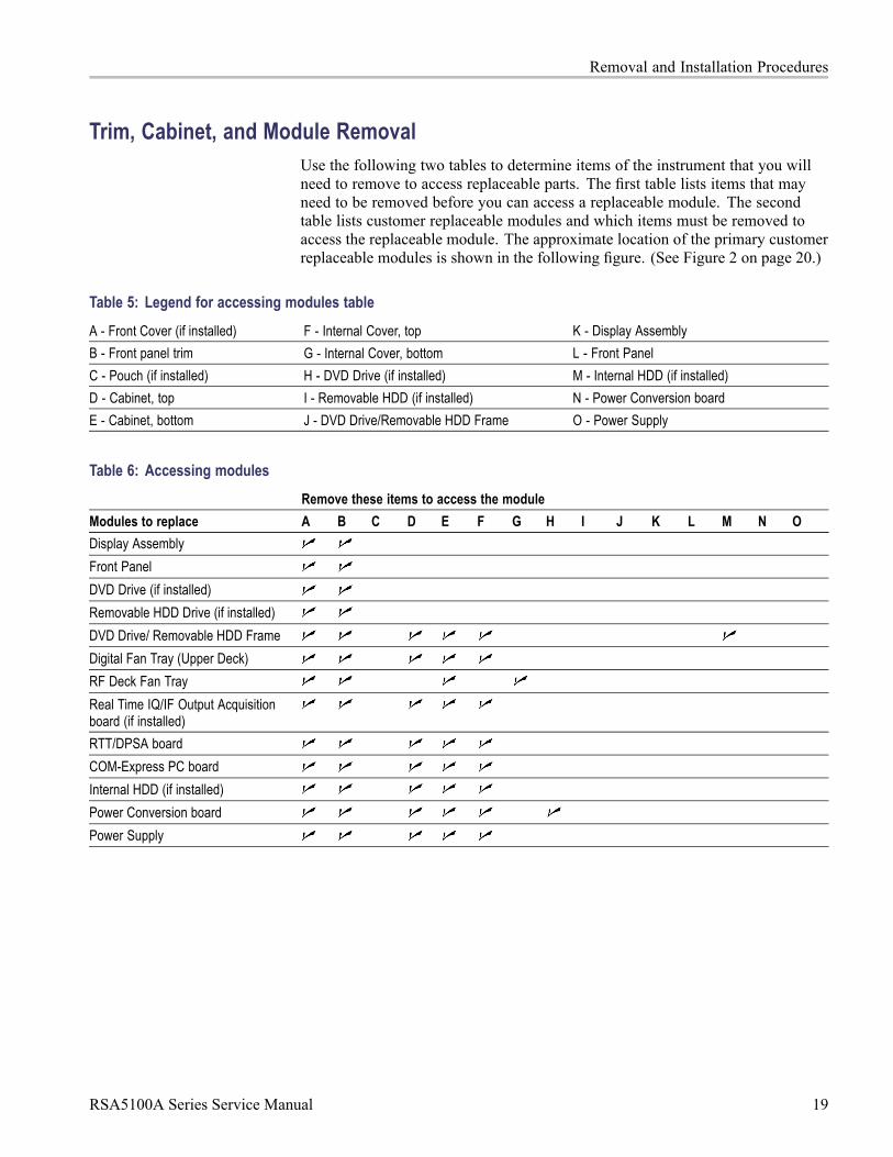
Trim, Cabinet, and Module RemovalUse the following two tables to determine items of the instrument that you willneed to remove to access replaceable parts. The first table lists items that mayneed to be removed before you can access a replaceable module. The secondtable lists customer replaceable modules and which items must be removed toaccess the replaceable module. The approximate location of the primary customerreplaceable modules is shown in the following figure. (See Figure 2 on page 20.)
Table 5: Legend for accessing modules table
A - Front Cover (if installed) F - Internal Cover, top K - Display Assembly
B - Front panel trim G - Internal Cover, bottom L - Front Panel
C - Pouch (if installed) H - DVD Drive (if installed) M - Internal HDD (if installed)
D - Cabinet, top I - Removable HDD (if installed) N - Power Conversion board
E - Cabinet, bottom J - DVD Drive/Removable HDD Frame O - Power Supply
Table 6: Accessing modules
Remove these items to access the module
Modules to replace A B C D E F G H I J K L M N O
Display Assembly
Front Panel
DVD Drive (if installed)
Removable HDD Drive (if installed)
DVD Drive/ Removable HDD Frame
Digital Fan Tray (Upper Deck)
RF Deck Fan Tray
Real Time IQ/IF Output Acquisitionboard (if installed)
RTT/DPSA board
COM-Express PC board
Internal HDD (if installed)
Power Conversion board
Power Supply
RSA5100A Series Service Manual 19

Removal and Installation Procedures
Figure 2: Power supply and HDD/DVD drive locations
20 RSA5100A Series Service Manual
Removal and Installation Procedures
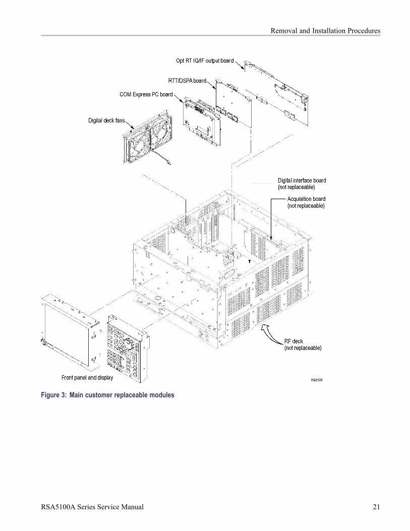
Figure 3: Main customer replaceable modules
RSA5100A Series Service Manual 21

Removal and Installation Procedures
Removal Procedures
NOTE. Unless directed otherwise, installation is the reverse of the removalprocedure.
These procedures assume you have access to the module you are removing. Usethe tables to determine which trim and/or modules to remove to gain access. (SeeTable 5 on page 19.) (See Table 6 on page 19.) A figure is also provided as a quickreference for customer replaceable module locations. (See Figure 2 on page 20.)
CAUTION. When removing or installing the keypad, make sure you do not touchthe switch contacts with your fingers. The oils in your fingers will degrade ordamage the switch contacts. To help prevent damage to the keypad use cottongloves when removing or installing the keyboard pad.
CAUTION. To avoid damage to the front panel Standby/On switch assembly, donot set the Display module assembly on a work surface. Sliding the instrumentover the edge of the work surface could break off the On/Standby switch assembly.
Display Perform these steps to remove the Display module:
1. Remove the four screws securing the display to the Main chassis; two on thetop and two on the left side.
2. Disconnect the cables from the COM Express PC board and keep the cablesconnected to the display assembly.
3. Gently remove the Display module from the Main chassis.
CAUTION. Be careful when removing and reinstalling the Display module cables.If the connectors have bent pins or are installed incorrectly the Display maybe destroyed.
4. Disconnect the smaller Display cable from J2 on the Display Adapter board.
5. Disconnect the larger Display cable from J3 on the Display Adapter board.
Front Panel Perform these steps to remove the Front Panel:
22 RSA5100A Series Service Manual

Removal and Installation Procedures
1. Disconnect the Front Panel cable from connector 71 on the Digital Interfaceboard.
2. Remove the six T15 screws that secure the Front Panel to the chassis; two onthe top, two on the right side, and two on the bottom front.
3. Pull the Front Panel assembly from the chassis.
Digital Deck Fans Perform these steps to remove the fan assembly from the digital deck:
1. Unplug the fan control cable from the Digital Interface board connector,marked Fan1 and Fan2.
2. Remove the four T15 TORX screws securing the fan assembly, located on theleft side of the instrument.
3. Lift the fan assembly up through the narrow slot between the side panel andthe card cage.
DVD Drive Follow these steps to remove the DVD drive (if installed):
1. Detach the DVD power and data cables from the COM Express PC board.
2. Carefully cut the zip tie from the DVD cables and pull the cables throughthe chassis hole.
3. Remove the two screws from the front panel of the DVD.
4. Pull the DVD drive out from the Main chassis, being careful to feed thecables as you pull.
5. Remove the four screws securing the DVD drive to the DVD drive bracket.
Removable Hard Disk Drive Perform these steps to remove the removable hard disk drive (if installed):
1. Loosen the thumbscrews securing the drive to the front panel.
2. Grasp the drive assembly by the thumb screws and pull the assembly straightout of the instrument.
3. Remove the four screws securing the hard drive to the bottom bracket.
Internal Hard Disk Drive Follow these steps to remove the internal hard disk drive:
NOTE. If you have a removable HDD mounted above the front panel, you willnot have an internal hard disk drive.
RSA5100A Series Service Manual 23
Removal and Installation Procedures
1. Remove the four T15 screws securing the hard disk drive assembly to thePower Supply shield.
2. Lift up hard disk drive to access and remove the power/data cable from thehard disk drive.
3. Disconnect the video cables from the COM Express PC board.
4. Lift the hard disk drive up and remove it from the Signal Analyzer.
5. Remove the four screws securing the hard drive to the bracket.
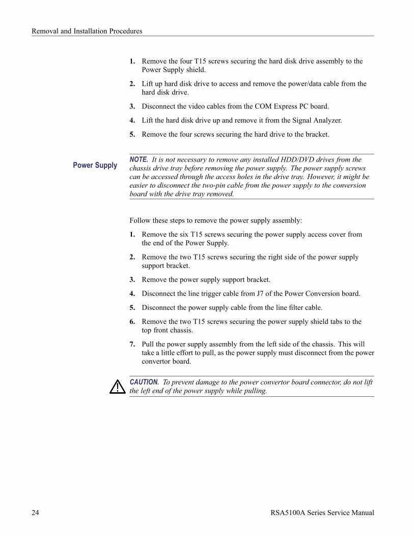
Power SupplyNOTE. It is not necessary to remove any installed HDD/DVD drives from thechassis drive tray before removing the power supply. The power supply screwscan be accessed through the access holes in the drive tray. However, it might beeasier to disconnect the two-pin cable from the power supply to the conversionboard with the drive tray removed.
Follow these steps to remove the power supply assembly:
1. Remove the six T15 screws securing the power supply access cover fromthe end of the Power Supply.
2. Remove the two T15 screws securing the right side of the power supplysupport bracket.
3. Remove the power supply support bracket.
4. Disconnect the line trigger cable from J7 of the Power Conversion board.
5. Disconnect the power supply cable from the line filter cable.
6. Remove the two T15 screws securing the power supply shield tabs to thetop front chassis.
7. Pull the power supply assembly from the left side of the chassis. This willtake a little effort to pull, as the power supply must disconnect from the powerconvertor board.
CAUTION. To prevent damage to the power convertor board connector, do not liftthe left end of the power supply while pulling.
24 RSA5100A Series Service Manual
Removal and Installation Procedures
Power Conversion Board Perform these steps to remove the Power Conversion board:
NOTE. Remove the Power Supply support bracket and the Power Supply beforeremoving the Power Conversion board.
1. Remove the cables connected to the Power Conversion board:
ATX POWER 20-pin cable
ANALOG POWER 12-pin cable
RF PWR 50-pin ribbon cable
Flat ribbon cable 10-pin cable
Line Trigger Sense 2-pin cable
2. Remove the five T15 screws securing the Power Converter board to thechassis.
3. Lift the Power Converter board from the Signal Analyzer.
COM Express PC Board Perform these steps to remove the COM Express PC board:
1. Remove the two screws securing the COM Express PC board to the mainchassis card guide.
2. Disconnect all cables attached to the COM Express PC board.
3. Lift the latch levers on the top edge of the COM Express PC board assemblyto disconnect it from the Digital Interface board.
4. Lift the COM Express PC board from the Signal Analyzer.
RSA5100A Series Service Manual 25

Troubleshooting
TroubleshootingWARNING. Before doing this or any other procedure in this manual, read theSafety Summary found at the beginning of this manual. Also, to prevent possibleinjury to service personnel or damage to the instrument components, readInstallation in the RSA5100A Series Real-Time Signal Analyzers Quick Start UserManual, available on the Web at www.tektronix.com/manuals, and PreventingESD in this section.
Troubleshooting contains information and procedures designed to help you isolatefaults to a module.
This subsection assumes that service personnel have the skills required to workon the Real-Time Signal Analyzer, including PC troubleshooting and Windowsoperating system skills. Details of PC and Windows operation and service arenot in this manual.
For assistance, please contact your local Tektronix Service Center.
26 RSA5100A Series Service Manual

Troubleshooting
Service LevelThis section contains information and procedures designed to help you isolatefaulty modules in the RSA5100A Series Real-Time Signal Analyzer. If a moduleneeds to be replaced, follow the Removal and Installation Procedures, located inthis section.
Check for Common ProblemsUse the following table to quickly isolate possible failures. The table listsproblems and possible causes. The list is not exhaustive, but it may help youeliminate a problem that is quick to fix, such as a blown fuse or loose cable.
Table 7: Failure symptoms and possible causes
Symptom Possible cause(s)
Instrument will not power on Power cord not plugged in
Faulty power supply (check Status LEDs)
Faulty power conditioner board
Faulty front panel power switch
Faulty display adapter board
Front panel light comes on (instrumentpowers on), but one or more fans willnot operate
Faulty fan cable
Defective fan assembly
Faulty power supply (check Status LEDs)
Faulty COM Express PC board
Faulty CPU
Digital Interface board problem
No beeps on startup or multiple beepson startup (single beep is OK)
Faulty COM Express PC board
Flat panel display blank BIOS setting not Advanced Chipset Features> - On Chip VGA > Enabled - Boot Display >CRT + LFP
Defective cable from PC Carrier board toDisplay Adapter board
Defective backlighting display
Faulty display
Faulty digital interface board
Faulty display adapter board
RSA5100A Series Service Manual 27

Troubleshooting
Table 7: Failure symptoms and possible causes (cont.)
Symptom Possible cause(s)
DVD-ROM related symptoms Defective DVD-ROM
Defective DVD-ROM drive cable
Defective DVD-ROM Adapter board
Incorrect DVD-ROM configuration in the BIOSsetup
Hard disk drive related symptoms Defective hard disk drive
Incorrect hard disk type selected in the BIOSsetup
Replaceable hard disk drive not installed
Power supply failure
Corrupted BIOS module firmware, reinstallfirmware
Loose cable
Corrupted OS image
Status Indicator LEDs Check that the Status Indicator LEDs are lit on the Power Converter and DigitalInterface boards to ensure the power supplies are operating. (See Figure 4.) (SeeTable 8.) (See Table 9.)
Figure 4: Status indicator locations
28 RSA5100A Series Service Manual

Troubleshooting
Table 8: Power Converter board LED status indicators
LED Status Indication
DS171 STANDBY
DS172 -15 V OK
DS173 -8 V OK
DS174 +8 V OK
DS175 +15 V OK
DS176 +30 V OK
Table 9: Digital Interface board LED status indicators
LED Status Indication
DS481 CLOCK FAIL (normally off)
DS482 +5 VSB OK
DS483 +5 V OK
DS484 +3.3 V OK
DS485 +2.5 V OK
DS486 +1.8 V OK
DS487 +1.5 V OK
DS488 FPGA INIT
DS489 FPGA DONE
DS4810 STATUS 0
DS4811 STATUS 1 (normally off)
DS911 +1.2 V OK
DiagnosticsThis section describes how to use and interpret the embedded DiagnosticsInterface for both the Power On Self Tests (POST) and the Extended Diagnosticstests. These tests determine whether there has been a module failure in theinstrument.
Power On Self Tests(POST)
The instrument runs Power On Self Tests (POST) automatically every timethe instrument is powered up. If a failure is detected during this process, theinstrument displays the Power-On Self Tests tab of the Diagnostics window to listwhich module(s) failed.
RSA5100A Series Service Manual 29

Troubleshooting
Select the Diagnostics Failure Info tab in the Diagnostics window for moreinformation about failures.
All failure information is logged in the Windows Event Viewer. To access theWindows Event Viewer, click the Event Viewer button on the Diagnostics FailureInfo tab. The Windows Event Viewer is also available in the Administrative Toolsportion of the Windows Control Panel.
NOTE. Check the timestamp in the Event Viewer, as errors are stored on diskand may be from earlier power cycles.
30 RSA5100A Series Service Manual

Troubleshooting
Diagnostics Tests The Diagnostics tab enables you to run any or all of the diagnostics tests in theinstrument, including the POST tests. To run diagnostics:
1. Select Tools > Diagnostics in the application menu bar.
2. Select the Diagnostics tab and click All Modules, All Tests.
3. Click Single Test in the Repeat area.
4. Click RUN. The instrument performs the selected tests. For tests that requiremanual intervention, follow the on-screen instructions to complete the tests.A green dot next to a test means that the marked test is currently running. Ifthe test completes successfully the green dot is replaced by a black checkmark. If the test fails, the green dot is replaced by a red X.
5. To run specific tests, select those tests in the list and use the Repeat segmentof the window to set the test run conditions. The Repeat controls (see thefollowing figure) let you:
A) Repeat the test(s) a specified number of times,
B) Repeat the test(s) until a failure occurs,
C) Repeat the test(s) continuously even if failures occur, or
D) Run the test(s) only one time.
RSA5100A Series Service Manual 31

Troubleshooting
Microsoft Windows EventViewer
The Microsoft Windows Event Viewer maintains a permanent record of instrumentdiagnostics failure information, with other messages regarding the operatingsystem. If there is not a shortcut to the Event Viewer on the desktop you canaccess it by clicking the Event Viewer button on the Diagnostics Failure Info tab.
To view the Diagnostics failure information, first click theWindows Logs iconin the left frame (under Event Viewer (Local)). Then click the Applicationsicon. The view changes to show the individual error reports, as shown in thefollowing figure.
Scroll through the Event list to locate error events. Pay attention to the dateand time stamps, as the information is a permanent record and shows failureinformation from earlier diagnostic sessions.
Also note that the Signal Analyzer diagnostic errors are labeled as TekRSA in theSource column, to differentiate them from operating system messages.
32 RSA5100A Series Service Manual

Troubleshooting
Scroll through the Event list to locate error events. Pay attention to the dateand time stamps, as the information is a permanent record and shows failureinformation from earlier diagnostic sessions.
Also note that the Signal Analyzer diagnostic errors are labeled as TekRSA in theSource column, to differentiate them from operating system messages.
Clicking on an error message to display error information in the General orDetails tabs located below the list.
Double-click an error message to open a separate window for that error message.The window shows the date and time the error message was generated and thesource of the error message. The text of the error message is shown in theDescription area. The three buttons at the upper right let you navigate through theerror list (using the up and down arrows), or sends the record to the default printer.
If you scroll down in the error description, the event viewer always adds a linethat says “For more information, see Help and Support Center at” and includes alink to Microsoft.com. Do not use this link, as Microsoft has no information onTektronix instrument error messages.
Click Help in the Event Viewer Menu bar to open the online help and learn moreinformation on using the Event Viewer.
RSA5100A Series Service Manual 33

Troubleshooting
Diagnostic Test ErrorMessages
The following tables list the instrument diagnostics error messages, withrecommended actions for each message.
Hardware Module (See Table 10 on page 35.)
Digital Interface board (See Table 11 on page 35.)
ADC board (See Table 12 on page 36.)
DPSA board (See Table 13 on page 37.)
RF Interface board (See Table 14 on page 38.)
LO1 Module (See Table 15 on page 39.)
LO2/Reference Oscillator (See Table 16 on page 40.)
Front Panel (See Table 17 on page 43.)
34 RSA5100A Series Service Manual

Troubleshooting
Table 10: Hardware module diagnostic error messages
Test Error message Recommended action
Uninitialized
See Event Viewer for moreinformation
The COM Express PC is not communicating with the Digital Interfaceboard. Restart the instrument and check the Event Viewer. If theproblem persists, send the instrument to Tektronix Service Center forrepair.
The Digital Interface Board was notfound.
Send the instrument to a Tektronix Service Center for repair.
Acquisition Board not found. Send the instrument to a Tektronix Service Center for repair.
The DPSA Board was not found. Replace RTT/DPSA board.
Load Acquisition Board Failed. Send the instrument to a Tektronix Service Center for repair.
RF Interface Board not found orFPGA Load failed.
Replace RF Interface board.
LO1 not found or FPGA Load failed. Send the instrument to a Tektronix Service Center for repair.
L02/Reference Oscillator not foundor FPGA Load failed.
Send the instrument to a Tektronix Service Center for repair.
The RF Converter board was notfound or the FPGA was not loaded.
Send the instrument to a Tektronix Service Center for repair.
Hardware Init
Unable to communicate with Digitalinterface board.
Possible Digital Interface Board problem. Restart the Signal Analyzer.If problem persists, return to Tektronix Service Center for repair.
Error reading ID’s. Send the instrument to a Tektronix Service Center for repair.ReadProgrammable PartVersions
Unable to communicate with PPC. Send the instrument to a Tektronix Service Center for repair.
Table 11: Digital Interface Board diagnostic error messages
Test Error message Recommended action
Digital Board IDVerification
Digital Interface Board IDVerification Failed.
Send the instrument to a Tektronix Service Center for repair.
Bad FPGA file path. Reinstall the RSA5100A product software.Digital Board FPGALoad Test Exception in Digital Interface FPGA
Load.
Done bit not returned high.
Send the instrument to a Tektronix Service Center for repair.
Digital Interface alternating 1's and0's R/W test failed.
Digital Interface reg R/W Walking1's test failed.
Send the instrument to a Tektronix Service Center for repair.Digital BoardRegister R/W Test
Unable to communicate with DigitalInterface Board.
Send the instrument to a Tektronix Service Center for repair.
SRAM memory failure at “memoryaddress”.
Send the instrument to a Tektronix Service Center for repair.Digital Board SRAMTest
Write value was “xxx”Read Value was “xxx”
Send the instrument to a Tektronix Service Center for repair.
RSA5100A Series Service Manual 35

Troubleshooting
Table 11: Digital Interface Board diagnostic error messages (cont.)
Test Error message Recommended action
Invalid number of return words. Send the instrument to a Tektronix Service Center for repair.Digital FIFO Test
Bad value in returned buffer. Send the instrument to a Tektronix Service Center for repair.
PPC returned unknown status. Send the instrument to a Tektronix Service Center for repair.PPC POST Results
PPC did not return POST status. Send the instrument to a Tektronix Service Center for repair.
Digital BoardAcquisition Test
Acquisition data at “offset xxx” wasnot correct.
Send the instrument to a Tektronix Service Center for repair.
Digital BoardSDRAM Test
Write failure. SDRAM addr:0xXXXX
Read failure. SDRAM addr:0xXXXX
Reseat the DIMM Acquisition memory module in the socket. If theproblem persists, send the instrument to a Tektronix Service Centerfor repair.
Digital BoardFLASH Test
Failed bit exclusion Test withpattern XXXX.
Validation failed at offset XXXX.
Blocks XXXX and XXXX aremirrored.
Send the instrument to a Tektronix Service Center for repair.
Digital Board 28 VoltSupply Test
Verification of this supply is doneby the operator.
If 28 V is not present at the rear-panel BNC connector, check the+28 V at the test point on the power conversion board. If the 28 Vis not present, replace the power conversion board. If the +28 V ispresent on the power conversion board, send the instrument to aTektronix Service Center for repair.
Digital Board AudioTest
No audio was heard. Verify that audio is not muted and level is set properly using WindowsVolume control. If this does not correct the problem, send theinstrument to a Tektronix Service Center for repair.
Table 12: ADC Board diagnostic error messages
Test Error message Recommended action
ADC board IDVerification
ADC Board Not Found in slot 1. Send the instrument to a Tektronix Service Center for repair.
Bad FPGA file path. The file wasnot found in the directory.
Send the instrument to a Tektronix Service Center for repair.
The Main FPGA load failed. Send the instrument to a Tektronix Service Center for repair.
The Buffer FPGA load failed. Send the instrument to a Tektronix Service Center for repair.
ADC board FPGALoad Test
DCM Not locked. Send the instrument to a Tektronix Service Center for repair.
ADC board RegisterR/W Test
ADC R/W test FAILED. Send the instrument to a Tektronix Service Center for repair.
ADC board LVDSTest
ADC LVDS test FAILED. Send the instrument to a Tektronix Service Center for repair.
ADC Free RunTrigger Test
ADC Free Run Trigger TestFAILED.
Send the instrument to a Tektronix Service Center for repair.
Unexpected data at offset X. Send the instrument to a Tektronix Service Center for repair.ADC board AcqPattern Test Trigger timeout occurred. Send the instrument to a Tektronix Service Center for repair.
36 RSA5100A Series Service Manual

Troubleshooting
Table 12: ADC Board diagnostic error messages (cont.)
Test Error message Recommended action
ADC board DitherTest
Dither amplitude test - Failed
Dither frequency test - Failed
Send the instrument to a Tektronix Service Center for repair.
ADC Over range. Signal too strong. Run signal path test. If the signal path test passesand this test fails, send the instrument to a Tektronix Service Centerfor repair.
Signal below -50 dBm. Verify that the IF cable from the RF deck to the ADC board IFconnector is firmly connected. Repeat the test, if the problempersists, send the instrument to a Tektronix Service Center for repair.
ADC boardNarrow Band CWAcquisition Test
No signal found in acquiredspectrum.
Verify Normalization source is functional by running the Signal Pathtest. If that test passes and this test still fails, send the instrument toa Tektronix Service Center for repair.
ADC Overrange Signal too strong. Run signal path test. If the signal path test passesand this test fails, send the instrument to a Tektronix Service Centerfor repair.
Signal below -50 dBm. Verify that the IF cable from the RF deck to the ADC board IFconnector is firmly connected. Repeat the test, if the problempersists, send the instrument to a Tektronix Service Center for repair.
ADC board LFAcquisition Test
No signal found in acquiredspectrum.
Verify Normalization source is functional by running the Signal Pathtest. If that test passes and this test still fails, send the instrument toa Tektronix Service Center for repair.
ADC Overrange Signal too strong. Run signal path test. If the signal path test passesand this test fails, send the instrument to a Tektronix Service Centerfor repair.
Signal below -50 dBm. Verify that the IF cable from the RF deck to the ADC board IFconnector is firmly connected. Repeat the test, if the problempersists, send the instrument to a Tektronix Service Center for repair.
ADC board WB IFAcquisition Tes
No signal found in acquiredspectrum.
Verify Normalization source is functional by running the Signal Pathtest. If that test passes and this test still fails, send the instrument toa Tektronix Service Center for repair.
Table 13: DPSA Board diagnostic error messages
Test Error message Recommended action
DPSA IDVerification
DPSA Board ID Verification Failed. If ID was not found or a board other than the DPSA Board was found,Version/ID is nonfunctional. Replace the RTT/DPSA Board.
Bad DPSA FPGA file path. The filewas not found in the directory.
Reinstall the RSA5100A Series product software.
DPSA FPGA Load Failed. Replace the RTT/DPSA board. If the problem persists, send theinstrument to a Tektronix Service Center for repair.
DPSA FPGA LoadTest
DCM Not locked. Replace the RTT/DPSA board. If the problem persists, send theinstrument to a Tektronix Service Center for repair.
RSA5100A Series Service Manual 37

Troubleshooting
Table 13: DPSA Board diagnostic error messages (cont.)
Test Error message Recommended action
Read/Write test failed (returns readand write values).
Replace the RTT/DPSA board. If the problem persists, send theinstrument to a Tektronix Service Center for repair.
DPSA Register R/WTest
CT Board QDR Control Failure. Replace the RTT/DPSA board. If the problem persists, send theinstrument to a Tektronix Service Center for repair.
FPGA File not found. Reinstall the RSA5100A Series product software.
FPGA Load Failed. Replace the RTT/DPSA board. If the problem persists, send theinstrument to a Tektronix Service Center for repair.
DPSA FrameTransfer Test
Frame data test failed when lookingfor incrementing pattern.
Replace the RTT/DPSA board. If the problem persists, send theinstrument to a Tektronix Service Center for repair.
DPSA LVDS Test The DPSA LVDS test failed. Replace the RTT/DPSA board. If the problem persists, send theinstrument to a Tektronix Service Center for repair.
DPSA board FM/AMAudio Test
No audio was heard. Replace the RTT/DPSA board. If the problem persists, send theinstrument to a Tektronix Service Center for repair.
Table 14: RF Interface Board diagnostic error messages
Test Error message Recommended action
RF Interface ID Test RF Interface Board not found. Run the PPC load test. This will rerun hardware discovery. If errorpersists, replace the RF Interface board.
RF Interface FPGALoad Test
FPGA Load failed. Replace RF Interface module.
38 RSA5100A Series Service Manual

Troubleshooting
Table 14: RF Interface Board diagnostic error messages (cont.)
Test Error message Recommended action
The 30 Volt supply is over voltage.
The 30 Volt supply is under voltage.
Replace the Power Conversion board. If the problem persists,replace the RF Interface board. If the problem persists, replacethe power supply. If the problem persists, send the instrument to aTektronix Service Center for repair.
The 8 Volt supply is over voltage.
The 8 Volt supply is under voltage.
Replace the Power Conversion board. If the problem persists,replace the RF Interface board. If the problem persists, replacethe power supply. If the problem persists, send the instrument to aTektronix Service Center for repair.
The 2.5 Volt supply is over voltage.
The 2.5 Volt supply is undervoltage.
Replace the Power Conversion board. If the problem persists,replace the RF Interface board. If the problem persists, replacethe power supply. If the problem persists, send the instrument to aTektronix Service Center for repair.
The 1.2 Volt supply is over voltage.
The 1.2 Volt supply is undervoltage.
Replace the Power Conversion board. If the problem persists,replace the RF Interface board. If the problem persists, replacethe power supply. If the problem persists, send the instrument to aTektronix Service Center for repair.
The –8 Volt supply is over voltage.
The –8 Volt supply is under voltage.
Replace the Power Conversion board. If the problem persists,replace the RF Interface board. If the problem persists, replacethe power supply. If the problem persists, send the instrument to aTektronix Service Center for repair.
RF InterfaceVoltage/Currenttest
The 8VSB supply is over voltage.
The 8VSB supply is under voltage.
Replace the Power Conversion board. If the problem persists,replace the RF Interface board. If the problem persists, replacethe power supply. If the problem persists, send the instrument to aTektronix Service Center for repair.
Table 15: LO1 Module diagnostic error messages
Test Error message Recommended action
L01 ID Test Board not found. Run the PPC load test. This will rerun hardware discovery. If errorpersists, send the instrument to a Tektronix Service Center for repair.
L01 FPGA LoadTest
FPGA Load failed. Send the instrument to a Tektronix Service Center for repair.
L01 Register R/WTest
Read /Write test failed. Send the instrument to a Tektronix Service Center for repair.
RSA5100A Series Service Manual 39

Troubleshooting
Table 15: LO1 Module diagnostic error messages (cont.)
Test Error message Recommended action
Sum Loop Error voltage exceedsHigh threshold
Sum Loop Error voltage exceedsLow threshold
Warning only.
YTO Loop Error voltage exceedsHigh threshold
YTO Loop Error voltage exceedsLow threshold
Warning only.
Yig loop is unlocked. Send the instrument to a Tektronix Service Center for repair.
Sum loop is unlocked. Send the instrument to a Tektronix Service Center for repair.
15 V supply voltage is over/undervoltage.
Run the RF Interface ADC test to verify a power supply problem.Check the Digital Interface board power supply status LEDs. (SeeTable 9.)
12 V supply voltage is over/undervoltage.
Run the RF Interface ADC test to verify a power supply problem.Check the Digital Interface board power supply status LEDs. (SeeTable 9.)
8 V supply voltage is over/undervoltage.
Run the RF Interface ADC test to verify a power supply problem.Check the Digital Interface board power supply status LEDs. (SeeTable 9.)
5 V supply voltage is over/undervoltage.
Run the RF Interface ADC test to verify a power supply problem.Check the Digital Interface board power supply status LEDs. (SeeTable 9.)
3.3 V supply voltage is over/undervoltage.
Run the RF Interface ADC test to verify a power supply problem.Check the Digital Interface board power supply status LEDs. (SeeTable 9.)
L01 Voltage/CurrentTest
L01 is over temp. Warning only.
Table 16: LO2/Reference Oscillator diagnostic error messages
Test Error message Recommended action
LO2 ID Test Board not found. Run the PPC load test. This will rerun hardware discovery. If errorpersists, send the instrument to a Tektronix Service Center for repair.
LO2 FPGA LoadTest
FPGA Load failed. Send the instrument to a Tektronix Service Center for repair.
L02 Register R/WTest
Read /Write test failed. Send the instrument to a Tektronix Service Center for repair.
40 RSA5100A Series Service Manual
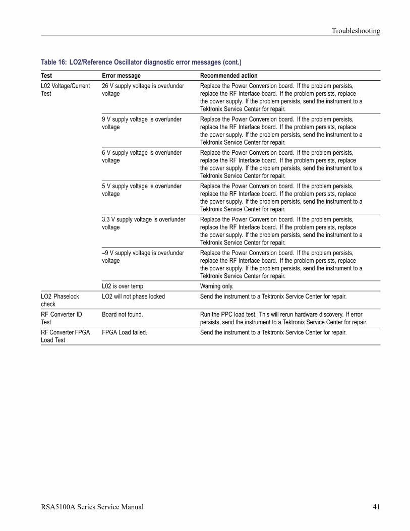
Troubleshooting
Table 16: LO2/Reference Oscillator diagnostic error messages (cont.)
Test Error message Recommended action
26 V supply voltage is over/undervoltage
Replace the Power Conversion board. If the problem persists,replace the RF Interface board. If the problem persists, replacethe power supply. If the problem persists, send the instrument to aTektronix Service Center for repair.
9 V supply voltage is over/undervoltage
Replace the Power Conversion board. If the problem persists,replace the RF Interface board. If the problem persists, replacethe power supply. If the problem persists, send the instrument to aTektronix Service Center for repair.
6 V supply voltage is over/undervoltage
Replace the Power Conversion board. If the problem persists,replace the RF Interface board. If the problem persists, replacethe power supply. If the problem persists, send the instrument to aTektronix Service Center for repair.
5 V supply voltage is over/undervoltage
Replace the Power Conversion board. If the problem persists,replace the RF Interface board. If the problem persists, replacethe power supply. If the problem persists, send the instrument to aTektronix Service Center for repair.
3.3 V supply voltage is over/undervoltage
Replace the Power Conversion board. If the problem persists,replace the RF Interface board. If the problem persists, replacethe power supply. If the problem persists, send the instrument to aTektronix Service Center for repair.
–9 V supply voltage is over/undervoltage
Replace the Power Conversion board. If the problem persists,replace the RF Interface board. If the problem persists, replacethe power supply. If the problem persists, send the instrument to aTektronix Service Center for repair.
L02 Voltage/CurrentTest
L02 is over temp Warning only.
LO2 Phaselockcheck
LO2 will not phase locked Send the instrument to a Tektronix Service Center for repair.
RF Converter IDTest
Board not found. Run the PPC load test. This will rerun hardware discovery. If errorpersists, send the instrument to a Tektronix Service Center for repair.
RF Converter FPGALoad Test
FPGA Load failed. Send the instrument to a Tektronix Service Center for repair.
RSA5100A Series Service Manual 41
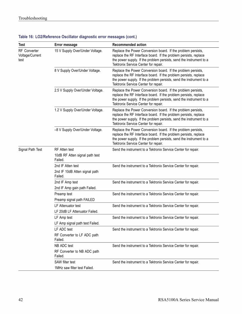
Troubleshooting
Table 16: LO2/Reference Oscillator diagnostic error messages (cont.)
Test Error message Recommended action
15 V Supply Over/Under Voltage. Replace the Power Conversion board. If the problem persists,replace the RF Interface board. If the problem persists, replacethe power supply. If the problem persists, send the instrument to aTektronix Service Center for repair.
8 V Supply Over/Under Voltage. Replace the Power Conversion board. If the problem persists,replace the RF Interface board. If the problem persists, replacethe power supply. If the problem persists, send the instrument to aTektronix Service Center for repair.
2.5 V Supply Over/Under Voltage. Replace the Power Conversion board. If the problem persists,replace the RF Interface board. If the problem persists, replacethe power supply. If the problem persists, send the instrument to aTektronix Service Center for repair.
1.2 V Supply Over/Under Voltage. Replace the Power Conversion board. If the problem persists,replace the RF Interface board. If the problem persists, replacethe power supply. If the problem persists, send the instrument to aTektronix Service Center for repair.
RF ConverterVoltage/Currenttest
–8 V Supply Over/Under Voltage. Replace the Power Conversion board. If the problem persists,replace the RF Interface board. If the problem persists, replacethe power supply. If the problem persists, send the instrument to aTektronix Service Center for repair.
RF Atten test
10dB RF Atten signal path testFailed.
Send the instrument to a Tektronix Service Center for repair.
2nd IF Atten test
2nd IF 10dB Atten signal pathFailed.
Send the instrument to a Tektronix Service Center for repair.
2nd IF Amp test
2nd IF Amp gain path Failed.
Send the instrument to a Tektronix Service Center for repair.
Preamp test
Preamp signal path FAILED
Send the instrument to a Tektronix Service Center for repair.
LF Attenuator test
LF 20dB LF Attenuator Failed.
Send the instrument to a Tektronix Service Center for repair.
LF Amp test
LF Amp signal path test Failed.
Send the instrument to a Tektronix Service Center for repair.
LF ADC test
RF Converter to LF ADC pathFailed.
Send the instrument to a Tektronix Service Center for repair.
NB ADC test
RF Converter to NB ADC pathFailed.
Send the instrument to a Tektronix Service Center for repair.
Signal Path Test
SAW filter test
1MHz saw filter test Failed.
Send the instrument to a Tektronix Service Center for repair.
42 RSA5100A Series Service Manual

Troubleshooting
Table 16: LO2/Reference Oscillator diagnostic error messages (cont.)
Test Error message Recommended action
Step Attenuator test Step Attenuator Failed. Send the instrument to a Tektronix Service Center for repair.
IF Attenuator Test The IF attenuator Failed. Send the instrument to a Tektronix Service Center for repair.
Preamp TestTest The Preamp Failed Send the instrument to a Tektronix Service Center for repair.
Table 17: Front Panel diagnostic error messages
Test Error message Recommended action
Front Panel LCD test failed. Replace the LCD display.Front Panel Test
Front Panel Button test failed. Replace the front panel keypad.
RSA5100A Series Service Manual 43

Troubleshooting
44 RSA5100A Series Service Manual

Replaceable PartsThis section contains a list of the replaceable modules for the RSA5100A SeriesReal-Time Signal Analyzers. Use this list to identify and order replacement parts.
Parts Ordering InformationReplacement parts are available through your local Tektronix field office orrepresentative.
Changes to Tektronix products are sometimes made to accommodate improvedcomponents as they become available and to give you the benefit of the latestimprovements. Therefore, when ordering parts, it is important to include thefollowing information in your order:
Part number
Instrument type or model number
Instrument serial number
Instrument modification number, if applicable
If you order a part that has been replaced with a different or improved part, yourlocal Tektronix field office or representative will contact you concerning anychange in part number.
Module Servicing Modules can be serviced by selecting one of the following three options. Contactyour local Tektronix service center or representative for repair assistance.
Module exchange. In some cases you may exchange your module for aremanufactured module. These modules cost significantly less than new modulesand meet the same factory specifications. For more information about themodule exchange program, call 1-800-833-9200. Outside North America,contact a Tektronix sales office or distributor; see the Tektronix Web site(www.tektronix.com) for a list of offices.
Module repair and return. You may ship your module to us for repair, after whichwe will return it to you.
New modules. You may purchase replacement modules in the same way as otherreplacement parts.
RSA5100A Series Service Manual 45

Replaceable Parts
Using the Replaceable Parts ListThis section contains a list of the mechanical and/or electrical components thatare replaceable for the instrument. Use this list to identify and order replacementparts. The following table describes each column in the parts list.
Column Column name Description
1 Figure & index number Items in this section are referenced by figure and index numbers to the exploded viewillustrations that follow.
2 Tektronix part number Use this part number when ordering replacement parts from Tektronix.
3 and 4 Serial number Column three lists the serial number at which the part was first effective. Columnfour lists the serial number at which the part was discontinued. No entry means thatthe part is usable for all serial numbers.
5 Qty The quantity of parts used.
6 Name & description An item name is separated from the description by a colon (:). Because of spacelimitations, an item name may sometimes appear as incomplete. Use the U.S.Federal Catalog handbook H6-1 for further item name identification.
Abbreviations Abbreviations conform to American National Standard ANSI Y1.1-1972.
46 RSA5100A Series Service Manual

Replaceable Parts
Table 18: External parts
Fig. & indexnumber
Tektronixpartnumber
Serial no.effective
Serial no.discont'd Qty Name & description
5-
-1
200-5163-01 1 COVER; TOP COSMETIC, ALUM; SAFETY CONTROLLED
367-0528-00 1 HANDLE, CARRYING; DUAL DUROMETER MOLDED, SAFETY CONTROLLED
**ATTACHED PARTS**
407-4887-00 1 BRACKET; HANDLE BASE, PC/ABS ALLOY
-2
**END ATTACHED PARTS**
-3 211-1265-00 2 SCREW, MACHINE, 8-32 X 1.000L PNH, BLACK OXIDE, T20, NYLOK, STEEL
-4 211-0720-00 4 SCR, ASSEM WSHR; 6-32 X 0.500, PNH, STEEL, ZINC FINISH, T15 TORX DR, MACHINE
RSA5103A, RSA5196A
-5 348-1648-00 4 FOOT; REAR W/CORD WRAP, THERMO PLASTIC; SAFETY CONTROLLED
-6 200-5173-00 1 COVER; BOTTOM, INTERNAL; SAFETY CONTROLLED
200-5196-00 B010100 B010423 1 COVER; BOTTOM COSMETIC; SAFETY CONTROLLED
RSA5103A, RSA5106A
-7
200-5196-01 B010423 1 COVER; BOTTOM COSMETIC; SAFETY CONTROLLED
-8 211-1224-00 11 SCREW, 6-32 X 0.375L, PNH, BLACK, T15, NYLOC
-9 348-1945-00 B010100 B010423 2 REAR FOOT, STATIONARY, (2) NYLON W GLASS FILL
-10 348-1947-00 B010100 B010423 4 CUSHION, FOOT; SANTOPRENE, (4) BLACK
-11 348-1951-00 B010100 B010423 2 FRONT FOOT ASSEMBLY, FLIP (2)
-12 211-1050-00 34 SCREW, MACHINE; 6-32 X 0.312 L, PNH, STEEL, ZINC FINISH, T15
-13 200-4519-00 1 COVER, FRONT; PC ABS,17.420L X 8.670W X 2.000TH,TEK BLUE
333-4619-00 1 COSMETIC FRONT ASSY; FRONT PANEL AND ACQUISITION TRIM
RSA5103A, RSA5106A
-14
333-4677-00 1 COSMETIC FRONT ASSY; FRONT PANEL AND ACQUISITION TRIM
RSA5115A, RSA5126A
-15 211-1224-00 3 SCREW, 6-32 X 0.375L, PNH, BLACK, T15, NYLOC
-16 101-0152-00 1 TRIM, FRONT; TRIM ACQUISITION
-17 200-5149-00 1 COVER; TOP, INTERNAL; SAFETY CONTROLLED
-18 407-5530-01 2 BRACKET, MOUNTING; CARRYING HANDLE
-19 367-0542-00 2 HANDLE ASSY, CARRYING; AL, SS, BLACK
-20 211-1230-00 4 SCREW; 10-32X.500 SOC CAP,18-8 ZINC PLATED STEEL
-21 212-0650-00 4 SCREW, MACHINE; 10-32 X 0.437, FLH, 100 DEG, SST PSVT, POZ
RSA5100A Series Service Manual 47

Replaceable Parts
Figure 5: External parts
48 RSA5100A Series Service Manual

Replaceable Parts
Table 19: Display, front panel, DVD, and removable hard drive
Fig. & indexnumber
Tektronixpartnumber
Serial no.effective
Serial no.discont'd Qty Name & description
6--1 200-5143-00 1 COVER; DVD
-2 407-5476-00 1 BRACKET; DVD DRIVE
-3 119-7678-00 1 OPTICAL, CD-RW/DVD-R/RW DVD+R/RW, 16.7 MB/SEC, 650MEG/8.5GIG, SATA/ATAPI;TEAC MODEL DV-W28S-Z3
-4 065-0877-02 1 DRIVE ASSEMBLY, WITH PACKAGING & COA; FIXED INTERNAL HARD DISK DRIVE,RSA5XXXA OPT 59
RSA5103A, RSA5106A
-5 407-5473-00 1 BRACKET; HARD DRIVE, 2.5 INCH REMOVABLE
-6 441-2620-01 1 CHASSIS; DRIVE BAY FRAME TOP
-7 211-1050-00 6 SCREW, MACHINE; 6-32 X 0.312 L, PNH, STEEL, ZINC FINISH, T15
-8 407-5337-00 1 HDD CABLE BRACKET
-9 174-5349-00 1 CABLE ASSY; SATA COMBO, HARD DRIVE CABLE WITH LATCH
-10 174-5650-00 1 CABLE, SATA-DVD, DATA AND POWER, SAFETY CONTROLLED
-11 211-0950-00 4 SCREW, MACHINE; M2X.4X3L, PHL, PNH, STEEL
-12 211-1050-00 16 SCREW, MACHINE; 6-32 X 0.312 L, PNH, STEEL, ZINC FINISH, T15
-13 614-1050-00 1 PANEL ASSEMBLY; FRONT, RSA5XXX SERIES
-14 174-5080-00 1 CA ASSY, SP; IDC, RIBBON, FRT PANEL TO DIG INTF, 2X10
-15 174-5101-00 1 CA ASSY, SP; IDC, RIBBON, AUDIO COM Express PC TO DIG INTERF, 2X5
-16 878-0814-00 1 CIRCUIT BRD ASSY; RSA ENCODER
RSA5115A, RSA5126A
-17 878-0417-00 1 CIRCUIT BD ASSY; USB I/O
-18 878-0411-00 1 CIRCUIT BD ASSY; FRONT PANEL CONTROL
-19 260-2903-00 1 SWITCH, KEYPAD FRONT PANEL
-20 333-4618-00 1 FRONT SUBPANEL ASSEMBLY
-21 366-A056-01 1 KNOB; GENERAL PURPOSE
-22 650-5304-00 1 MODULE ASSY; DISPLAY WITH 119755000 LCD
-23 259-0155-01 1 FLEX CIRCUIT; POWER SWITCH, W/LED
-24 407-5504-00 1 BRACKET, DISPLAY FRONT; SAFETY CONTROLLED
-25 119-7537-00 1 TOUCH SCREEN ASSEMBLY, 10.4 IN, RESISTIVE, 5-WIRE, W/GASKETS
-26 119-7550-00 1 DISPLAY MODULE; LCD; 1024 X 768; 10.4 INCHES DIAGONAL, TFT, LED BACK LIGHT
-27 407-5548-00 1 BRACKET, DISPLAY
-28 878-0414-00 1 CIRCUIT BD ASSY; INTERCONNECT DISPLAY ADAPTER BRD
-29 174-5087-00 1 CA ASSY, SP; IDC, RIBBON, DISP ADAPT TO DIG INTERF, 2MM, 2X15
RSA5103A, RSA5106A
-30 174-5086-00 1 CA ASSY, SP; IDC, RIBBON, DISP ADAPT TO DIG INTERF, 2MM, 2X10
RSA5103A, RSA5106A
RSA5100A Series Service Manual 49

Replaceable Parts
Figure 6: Display, front panel, DVD, and removable hard drive
50 RSA5100A Series Service Manual

Replaceable Parts
Table 20: Modules
Fig. & indexnumber
Tektronixpartnumber
Serial no.effective
Serial no.discont'd Qty Name & description
878-0372-00 1 CIRCUIT BOARD ASSY; COM EXPRESS PC BOARD, PB-FREE
RSA5105A, RSA5106A
7-1
878-0831-00 1 CIRCUIT BOARD ASSY; PC CARRIER,BOMBLDA,PB-FREE
RSA5115A, RSA5126A
-2 407-5478-00 1 BRACKET, COM EXPRESS CARRIER; SAFETY CONTROLLED
-3 211-1050-00 10 SCREW, MACHINE; 6-32 X 0.312 L, PNH, STEEL, ZINC FINISH, T15
039-0190-00 1 PROCESSOR MODULE; PCI, SOM-5786
RSA5105A, RSA5106A
-4
039-0209-00 1 PROCESSOR MODULE; PCI, COM-E, MODIFIED ESM-GM45, BCM, MODULE ONLY
RSA5115A, RSA5126A
119-7490-00 1 FAN, TUBEAXIAL; 12 VDC, 0.073A, 0.876W, 6500 RPM, 6.0 CFM, 40MM X 10MM,W/LEADS; SAFETY CONTROLLED
RSA5105A, RSA5106A
-5
119-7683-00 1 FAN, 70MM X 70MM X 15MM, 12V
RSA5115A, RSA5126A
211-1346-00 4 SCREW, MACHINE, PANHEAD M3 X 0.5 X 26MM, PHILLIPS
RSA5105A, RSA5106A
-6
211-1444-00 4 SCREW, MACHINE, PANHEAD M3 X 0.5 X 24MM, PHILLIPS, SS ZINC
RSA5115A, RSA5126A
-7 863-0273-00 1 CIRCUIT BD ASSY; RTT/DPSA, PB-FREE
-8 407-5358-00 1 BRACKET, HEATSINK FAN
-9 436-0435-00 1 FAN ASSEMBLY
-10 664-5898-04 1 CIRCUIT BD ASSY; REALTIME I/Q OUTPUT (OPT 55)
-11 200-4961-00 1 COVER; REAR PANEL, OPTION (BLANK)
-12 211-0450-00 4 SCREW, MACHINE; 2.5MM X 0.45 X 6MM, PNH, STEEL, ZINC PLATED, T8 TORX
-13 200-5195-00 1 COVER; REAR PANEL, OPTION (IQ OUT, IF OUT); SAFETY CONTROLLED: OPTION 05
-14 200-4961-00 1 COVER; REAR PANEL, OPTION (BLANK)
-15 174-5106-01 2 CA ASSY, SP;IDC, TW FLAT, I&Q OUTPUT TO REAR PANEL
-16 407-5181-00 1 BRACKET, GROUNDING (LAN AND PS/2)
RSA5100A Series Service Manual 51

Replaceable Parts
Figure 7: Modules
52 RSA5100A Series Service Manual

Replaceable Parts
Table 21: Power supply and internal hard drive
Fig. & indexnumber
Tektronixpartnumber
Serial no.effective
Serial no.discont'd Qty Name & description
8-1 119-6986-06 1 POWER SUPPLY; AC-DC;460W;+3.3V 40A, +5V 34A, +12V 25A, -12V 1A, +5VSB2A;90-264VAC, 47-440HZ
-2 211-0718-00 6 SCREW, MACHINE; 6-32 X 0.312, FLH100, STEEL, ZINC FINISH, T-10 TORX
-3 407-5477-00 1 BRACKET; POWER SUPPLY; SAFETY CONTROLLED
-4 441-2619-00 1 CHASSIS; DRIVE TRAY
-5 211-1050-00 9 SCREW, MACHINE; 6-32 X 0.312 L, PNH, STEEL, ZINC FINISH, T15
-6 407-5472-00 1 BRACKET; HARD DRIVE, 3.5 INCH HARD DRIVE
-7 065-0878-02 1 DRIVE ASSEMBLY, WITH PACKAGING & COA; FIXED INTERNAL HARD DISK DRIVE,OPT 57.
RSA5103A, RSA5106A
-8 174-5089-00 1 CA ASSY, PWR; DISCRETE, DIG INTERFACE, 2X10, 18AWG; SAFETY CONTROLLED
-9 174-5090-00 1 CA ASSY, PWR; DISCRETE, DIG INTERFACE, 2X6, 20AWG; SAFETY CONTROLLED
-10 174-5101-00 1 CA ASSY, SP; IDC, RIBBON, AUDIO COM Express PC TO DIG INTERF, 2X5, 2MM;SAFETY CONTROLLED
-11 174-5100-00 1 CA ASSY, PWR; IDC, RIBBON, PWR CONV TO BULKHEAD, 2X25, 0.100 CTR; SAFETYCONTROLLED
B010100 B010431 CIRCUIT BD ASSY; POWER CONVERSION
RSA5103A
863-0470-00
B010100 B010436
1
RSA5106A
B010432 CIRCUIT BD ASSY; POWER CONVERSION
RSA5103A
B010437 RSA5106A
-12
863-0470-01
B010100
1
RSA5115A, RSA5126A
-13 211-0510-00 8 SCREW, MACHINE; 6-32 X 0.375, PNH, ZINC PLATED STEEL, T15
-14 200-5135-00 1 COVER, POWER SUPPLY
-15 174-5227-00 1 CABLE ASSY;LINE FILTER; SAFETY CONTROLLED
-16 211-0380-00 2 SCREW, MACHINE; 4-40 X 0.375, FLH, STEEL, ZINC FINISH, T8
RSA5100A Series Service Manual 53
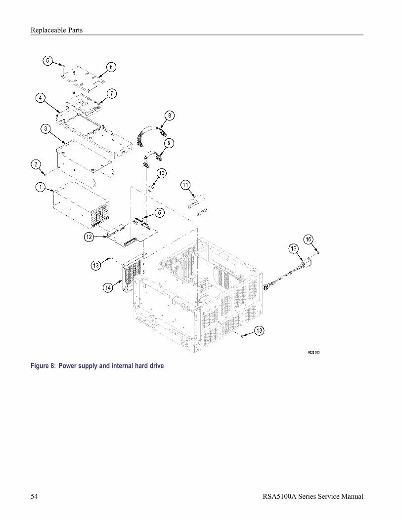
Replaceable Parts
Figure 8: Power supply and internal hard drive
54 RSA5100A Series Service Manual

Replaceable Parts
Table 22: Upper deck fans, misc. cables
Fig. & indexnumber
Tektronixpartnumber
Serial no.effective
Serial no.discont'd Qty Name & description
9-1 211-1050-00 16 SCREW,MACHINE; 6-32 X 0.312 L,PNH, STEEL, ZINC FINISH, T10, TORX
436-0424-00 1 ASSY,FAN TRAY; WITH FANS MOUNTED (UPPER DECK); SAFETY CONTROLLED
119-7182-00 2 FAN, TUBEAXIAL; 12VDC, 0.40A, 4.80W, 2500RPM, 100.6CFM, 120MM, LEADS W/CONN;SAFETY CONTROLLED (SUBPARTS OF 436-0424-00)
-2
407-5062-00 1 BRACKET; FAN MOUNTING,UPPER DECK; SAFETY CONTROLLED (SUBPART OF436-0424-00)
-3 174-5212-00 1 CA ASSY,SP; IDC, RIBBON, CONTROL LINES, BULKHEAD TO RF INTERFACE,2X7,0.100 CTR SAFETY CONTROLLED
-4 174-5201-00 1 CA ASSY,SP; IDC, RIBBON, GPIB, DIG INTF TO REAR PANEL; SAFETY CONTROLLED
-5 213-1061-00 2 JACKSCREW; 6-32 EXT THD, M3.5 X 0.6-6 INT THD, 410 SS
-6 407-5055-00 1 BRACKET ASSY; SPEAKER
-7 119-7172-00 1 SPEAKER; DYNAMIC; 28MM DIA, 8 OHM, 600-7KHZ, MYLAR CONE, MG ELECT288BB20 WITH 28 INCH CABLE
-8 407-5480-00 1 BRACKET; BNC ADAPTER
-9 174-5066-00 2 CA ASSY,RF,FLEX-COAX; FRONT PANEL ACQ
RSA5100A Series Service Manual 55

Replaceable Parts
Figure 9: Upper deck fans, misc. cables
56 RSA5100A Series Service Manual