rsc advances - binghamton universityws.binghamton.edu/me/zhou/zhou-publications/rsc - reduction of...
TRANSCRIPT
RSC Advances
PAPER
aDepartment of Mechanical Engineering and
Science and Engineering, State University
USA. E-mail: [email protected] of Physics, State University of N
Cite this: RSC Adv., 2014, 4, 30259
Received 28th May 2014Accepted 30th June 2014
DOI: 10.1039/c4ra05012f
www.rsc.org/advances
This journal is © The Royal Society of C
Reduction of CuO nanowires confined by a nanotest tube
Lu Yuan,a Abram G. Van Der Geest,b Wenhui Zhu,a Qiyue Yin,a Liang Li,a
Aleksey N. Kolmogorovb and Guangwen Zhou*a
Using in situ transmission electron microscopy observations of the thermally induced reduction of CuO
nanowires sheathed by a carbon shell, we show that a confined nanoscale geometry leads to changes in
the oxide reduction mechanism from a surface dominated process to the bulk dominated process. It is
shown that the reduction of carbon-confined CuO nanowires occurs via oxygen vacancy clustering in
the bulk that results in the nanowire fragmentation into Cu2O segments encapsulated by the carbon
shell while the reduction of un-confined CuO nanowires proceeds via the nucleation and growth of
Cu2O islands on the nanowire surface. The comparative in situ TEM observations demonstrate that the
surface coating layer reduces the thermal stability of the oxide nanowires, which is in contrast to the
commonly anticipated effect of enhancing the nanostructure stability by developing a surface protective
coating layer. Our density functional theory analyses reveal that the effects of oxygen vacancy ordering
at the surface and in the bulk of CuO are comparable in energy, which support the alternative reduction
process observed in the bulk of the sheathed CuO nanowires.
1. Introduction
Metal oxides are of great importance to a large variety ofchemical and materials applications ranging from catalysis toelectronic devices. The reduction of metal oxides, a reaction ofremoving lattice oxygen, plays a crucial role for these applica-tions.1–3 For instance, pure stoichiometric oxides usually do notexhibit high catalytic activity and oxide reduction is frequentlyemployed to modify their adsorption properties.4–9 Otherprocesses of oxide reduction include fabrication of electronicdevices, magnetic memory components, active/passive solarmaterials, solid-oxide fuel cells and oxygen separationmembranes, where metal oxides are used as working mate-rials.10–14 Traditionally, the reduction of metal oxides has beendescribed using the nucleation and growthmodel or the interfacemodel.2,3,15,16 In the nucleation and growth model, generation ofsmall nuclei of the new phase (a lower oxide) occurs on theparent oxide and the reaction interface area increases untilgrowing nuclei coalesce and then decreases.2,15–18 In the inter-face model, the rapid formation of a uniform and continuouslayer of the reduced phase on the parent oxide occurs and thereaction boundary moves inward as the reactionproceeds.2,15–17,19 Although these phenomenological modelshave been found useful in the description of the reduction of
Multidisciplinary Program in Materials
of New York, Binghamton, NY 13902,
ew York, Binghamton, NY 13902, USA
hemistry 2014
bulk oxides,15,16,18,20–22 here we show that they do not apply to thereduction of conned CuO nanowires. Our in situ TEM obser-vations of the reduction of carbon-sheathed CuO nanowiresreveal that the reduction of the geometrically conned oxidesfollows an internal reaction process initiated by forming oxygenvacancies in the bulk rather than on the surface, which deviatessignicantly from the surface-dominated reduction mecha-nisms assumed by the aforementioned phenomenologicalmodels. The results also unravel a unique feature of the surfaceconnement effect on the oxide reduction –modifying the bulkstoichiometry, which is typically limited to the surface regionfor unconned surfaces.
CuO nanowires are chosen for our study because the nano-wire morphology presents a highly anisotropic structure and itis of fundamental and technological interest to understand howoxide-reduction induced physical transformations take placewithin one-dimensional systems. In this context, the reductionof one-dimensional oxide nanostructures may lead to substan-tial changes in size, shape, and reaction intermediates providedthat the nanoscale systems are free to evolve in volume andsurface area. We use a volume-restricting carbon shell as a nanotest tube to examine the effect of the geometrical connementon the reaction morphology and pathway. Using in situ trans-mission electron microscopy (TEM), we deposit a rigid carboncoating layer around a CuO nanowire and image it as it is beingreduced upon heating over 400 �C. Using this method, thereduction pathway and reaction morphology can be measuredwithout signicant change in reaction volume throughout thereduction process. By comparing with the reduction behavior of
RSC Adv., 2014, 4, 30259–30266 | 30259

RSC Advances Paper
un-conned CuO nanowires, we nd that the surface conne-ment leads to a reduction process that does not follow either thenucleation and growth mechanism or the interface mechanism.
Among many metal oxides, the reduction of copper oxides isan important reference system for understanding the reductionmechanism.14–16,20,21,23–28 Cu oxides form three distinct phasesCuO (cupric), Cu2O (cuprous), and Cu4O3 (paramelaconite). Inaddition to being a long-debated question in solid-state chem-istry, the existence of the suboxides during the reduction of CuOis closely related to the ongoing quest for the active oxide phasein heterogeneous catalysis such as the water–gas shi reaction,methanol synthesis, and methanol oxidation,29–34 where thereduction of copper oxides is frequently involved. Here we showthat the thermally driven reduction of CuO nanowires results inthe formation of Cu2O without involving the intermediate phaseof Cu4O3. We further demonstrate that the carbon-sheathedCuO nanowires show less stability toward the thermal reductioncompared to the unsheathed CuO, i.e., the sheathed CuOnanowires cannot withstand the same high temperature as theunsheathed CuO nanowires for maintaining the one-dimen-sional nanowire morphology, which is in contrast to thecommonly expected effect of enhancing the stability of nano-structures by developing a surface coating layer.
2. Experimental and theoreticalapproaches
The CuO nanowires used for the reduction experiments wereprepared by oxidizing a polycrystalline Cu foil (99.99% purity,obtained from Sigma-Aldrich) at 450 �C for 2 h in a vacuumchamber lled with oxygen gas with the pressure of 200 Torr.This yields well-aligned CuO nanowires perpendicular to the Cusubstrates.35–37 For TEM imaging of the reduction process, CuOnanowires removed from the Cu substrate were suspended inethanol with ultrasonication for 5 min and then drop cast ontoa lacey carbon TEM grid, which was mounted onto a Gatanheating holder with rapid heating capability using a Gatan hotstage temperature controller. The TEM holder was loaded into aJEOL JEM2100F TEM. In order to conne the nanowire, carbonwas deposited onto the CuO nanowires under TEM electronbeam illumination during the heating process. Carbon shellformation induced by electron beam irradiation in the TEM iswell-known to occur as a result of interaction between theelectron beam and hydrocarbons adsorbed on the electronbombarded surface.38–40 To examine if the carbon coating layerplays any chemical effect on the oxide reduction, a Sundewatomic-layer deposition (ALD) system was also employed todeposit a thin amorphous Al2O3 layer on CuO nanowires forcomparing the reduction morphology and products.
Concurrent with the experimental observations, we havecarried out ab initio calculations to compare the energetics ofCuO reduction at surface and in the bulk. It has been widelydiscussed41,42 that the description of copper oxides requirescareful treatment of the strongly correlated effects for partiallylled Cu 3d states with DFT + U43 or hybrid functionals, such asHSE06.44 We employ DFT + U (with the Perdew–Burke–
30260 | RSC Adv., 2014, 4, 30259–30266
Ernzerhof functional45 and the previously selected U–J value of6.52 eV (ref. 46)) since this efficient method has been shown togive reliable energetics of VO formation (with a small over-estimation by 0.2–0.4 eV/VO compared to the HSE06 values).42
We have used a 500 eV cut-off in all calculations including ionicrelaxations and full unit cell optimizations. 8 � 8 � 8 and 5 � 5� 1 k-point meshes have been generated for the bulk and the(111) surface calculation of the CuO phase, respectively, toensure numerical convergence of relative energies to within 2–3meV per atom. We have used spin polarized calculations toaccount for the known antiferromagnetic ordering in Cu–Ophases.47 The magnetic moments were found to be close to�0.71 mB for 4-fold coordinated Cu2+ cations in the simulatedCuO and derived structures. In calculations of the (111) CuOsurface we have xed the 2 � 1 base with DFT + U-optimizedlattice parameters a ¼ 5.852 A, b ¼ 6.219 A, and g ¼ 102.74 andseparated the slabs with at least 12 A of vacuum. All surface andvacancy calculations included full ionic relaxations. Theresulting (111) CuO surface energy of 0.74 J m�2 agrees well withthe previously reported 0.72–0.74 J m�2 values obtained withDFT + U.42,48 The calculation of vacancy formation energies,EVO
¼ ECumOn�1� ECumOn
+ mO, requires a proper choice of theelemental chemical potentials mO. The T ¼ 0 K energy for anisolated O2 molecule calculated with DFT is typically adjustedwith a P and T-dependent term to account for the entropy of O inthe gaseous state as discussed in ref. 42. Fortunately, our studyfocuses primarily on the evaluation of the difference in the VO
formation at the surface and in the bulk which does notrequire mO.
3. Results and discussion
Fig. 1 shows a time-sequential series of in situ TEM images of aCuO nanowire during the heating process. As seen in Fig. 1(a),the straight CuO nanowire has a uniform diameter of �100 nmwith smooth surface. A thin layer of amorphous carbon wasdeveloped around the oxide nanowire at room temperature dueto the electron bean irradiation. The uniform TEM contrastsuggests that the nanowire has a single crystalline structurewithout signicant structural defects. With increasing thetemperature, the carbon layer thickened and reached a nalthickness of �350 nm at the bulge area at �260 �C. Furtherincrease in temperature resulted in no obvious change in thethickness of the carbon coating layer. When the temperaturereached 266 �C, the TEM contrast within the nanowire becamenon-uniform. This feature became more obvious at the highertemperature as shown in Fig. 1(e), where the visible voids aremarked by red circles. By comparing Fig. 1(e and f), one can seethat the void marked by the smaller red circle in Fig. 1(e) dis-appeared at the higher temperature, suggesting there wasmassive atom migration during the oxygen release. Increasingthe temperature to 427 �C resulted in drastically enhancedreaction kinetics. Fig. 1(g and h) reveal that the voids started tomerge, and within just one minute, the long nanowire becamefragmented, resulting in a large gap between the fragmentedsegments.
This journal is © The Royal Society of Chemistry 2014

Fig. 1 (a–h) Time sequential in situ TEM images of a single CuO nanowire as it was heated. The carbon layer increased in thickness initially andreached its final thickness at 266 �C. The oxide reduction occurs initially via losing oxygen thereby forming oxygen vacancies in the bulk while stillretaining the CuO lattice structure, followed by fragmentation into Cu2O segments at�427 �C. (i) SAED pattern from the circle areamarked in (g);(j) SAED pattern taken from the nano segment indicated by the dashed red circle in (h); (k) EDS result from the area marked by the dashed redcircle in (h).
Fig. 2 (a) A low magnification bright field TEM image showing theoverview of the sample after the reduction at�427 �C, where a portion(left-hand side) of the CuO nanowire indicated by the red-dashedrectangular box was continuously illuminated by TEM electron-beamto form a carbon shell while the rest of the sample was outside of theTEM electron-beam illumination. (b) A closer TEM view from the red-dashed rectangular area indicated in (a); (c) a representativeSAED pattern and (d) EDS from the bulges indicated by red-dashedcircles in (a).
Paper RSC Advances
Fig. 1(i) is a selected area electron diffraction (SAED) patternfrom the nanowire before the fragmentation (i.e., Fig. 1(f)),which reveals that the oxide nanowire still has the CuO struc-ture. Fig. 1(j) is a SAED pattern from the small segment formedfrom the fragmentation as indicated by the red circle in Fig. 1(h)and its indexingmatches well with the crystal structure of Cu2O.Fig. 1(k) is an X-ray energy dispersive spectrum (EDS) from thesame area indicated by the red circle in Fig. 1(h), whichconrms that the segment contains both Cu and O and theiratomic ratio is close to Cu2O. The in situ TEM observationreveals that the CuO nanowire is reduced to Cu2O by an abruptfragmentation process without involving the nucleation andgrowth of Cu2O particles.
As described earlier, the carbon shell formation is inducedby the electron beam irradiation. This can be further conrmedby a zoomed-out TEM view of a reduced sample. Fig. 2(a) showsa low-magnication TEM image showing the overall view of thesample aer the thermal reduction at the peak temperature of427 �C, where a portion (right-hand side) of the nanowire withinthe red dashed rectangle was originally illuminated by the TEMelectron beam that resulted in the formation of a carbon shellwhile the rest of the sample area was outside of the TEM illu-mination. One can see that the nanowires without the TEMelectron-beam illumination maintained their bare surface (i.e.,no carbon shell formation) and showed a completely differentreaction morphology compared to the electron-beam illumi-nated area. As indicated by dashed red circles in Fig. 2(a), smallbulges were formed on the surface of bare nanowires aer the
This journal is © The Royal Society of Chemistry 2014
thermal reduction. Fig. 2(b) is a zoomed-in TEM image from thearea indicated by the red dashed rectangle in Fig. 2(a), wherethe lower-right hand area was continuously illuminated by TEM
RSC Adv., 2014, 4, 30259–30266 | 30261

RSC Advances Paper
electron beam during the reduction while the upper-le handcorner was originally outside of the electron beam illumination.It can be seen that the nanowire illuminated by the electronbeam developed a thick carbon shell and fragmented into twoCu2O segments as identied by electron diffraction analysis,consistent with the result shown in Fig. 1. The CuO nanowireoutside the electron beam irradiation during the heatingprocess was reduced to form bulges without clear fragmenta-tion. Fig. 2(c) shows a representative electron diffraction patternobtained from the small bulges formed on the unsheathed CuOnanowires (i.e., no carbon shell), as indicated by the red circlesshown in Fig. 2(a), which reveals that they are Cu2O particles.Fig. 2(d) shows the EDS measurement of the bulged areas,which indicates that the particles contain both Cu and O. TheEDS composition analysis shown in Fig. 2(d) indicates that theatomic ratio of Cu to O is 2.79 : 1, which is greater than thestoichiometric ratio of 2 : 1 for a perfect Cu2O structure. Thissuggests that the oxide reduction resulted in a large amount ofoxygen vacancies in the Cu2O particle due to the removal oflattice oxygen.
The TEM observations above reveal the dramaticallydifferent reaction morphologies for carbon-sheathed CuOnanowires and unsheathed CuO nanowires. Carbon-sheathedCuO nanowires were reduced to Cu2O by fragmentation whileunsheathed CuO nanowires were reduced to Cu2O by formingbulges on the nanowire surface. To further verify their differ-ence, we used plasma cleaning (Solarus, Model 950) to removeadsorbed hydrocarbon on the as-prepared CuO nanowires inethanol, and then performed the similar in situ TEM heating
Fig. 3 (a–h) Time sequential in situ TEM images taken from a plasma-clearound area marked in (h); (j) Size evolution of the two Cu2O particles m
30262 | RSC Adv., 2014, 4, 30259–30266
experiment. Fig. 3 shows time-sequential in situ TEM images ofthe morphology transformations of a plasma-cleaned CuOnanowire during the in situ heating process. One can see clearlythat there was no carbon shell formation around the oxidenanowire during the entire heating process. Meanwhile, thenanowire had no signicant morphology change until thetemperature reached 327 �C, at which the CuO nanowire surfacebecame roughened (Fig. 3(b)) compared to the initially smoothsurface. When the temperature reached 397 �C, a small round-shaped particle became visible on the CuO nanowire surface(Fig. 3(c)). The particle grew larger while the diameter of theCuO nanowire shrank with increasing reduction temperature.At the temperature of 444 �C, the particle size grew to �160 nmbut the nanowire diameter shrank to �120 nm from its originaldiameter of 160 nm (Fig. 3(d)). At 449 �C, another small particleappeared visible on the CuO nanowire surface as shown inFig. 3(e). The two particles kept growing and gradually coalescedupon the continued CuO reduction (Fig. 3f–h). Fig. 3(i) is anSAED pattern obtained from the merged particle as indicated bythe dashed red circle in Fig. 3(h). Indexing of the diffractionpattern matches well with the Cu2O structure. This alsoconrms the result shown in Fig. 2, i.e., unsheathed CuOnanowires were reduced to Cu2O by forming Cu2O bulges.Compared to the reduction of carbon-sheathed CuO nanowiresthat results in fragmented segments of Cu2O at the peaktemperature of 427 �C with a total annealing time of 67 min(Fig. 1), reduction of the unsheathed CuO nanowire occurs vianucleation and growth of Cu2O bulges on the nanowire surfacewithout fragmenting the original nanowire, even aer being
ned CuO nanowire as it was heated; (i) SAED pattern obtained from theeasured from the in situ TEM observations.
This journal is © The Royal Society of Chemistry 2014

Paper RSC Advances
reduced at a higher peak temperature (T¼ 462 �C) while almostdoubling the annealing time (128 min). This demonstrates thatthe unsheathed CuO nanowires are more stable than the carbonsheathed CuO nanowire in terms of maintaining the one-dimensional nanowire morphology.
As more O atoms leave the oxide lattice, there are moreoxygen vacancies in the oxide. Therefore, it is reasonable toexpect that the diffusion rates of Cu and O increase withreduction time. As a result, the oxide reduction kinetics can beautocatalytic. To check if the oxide reduction is indeed auto-catalytic, we measured the size evolution of the two Cu2Oparticles in the course of the reduction of the CuO nanowirefrom the in situ TEM observation as shown in Fig. 3(a–h).Fig. 3(j) shows the measured sizes of the two Cu2O particles as afunction of reduction time, which exhibits a typical sigmoidcurve of an autocatalytic reaction, i.e., the rate of reaction is lowin the beginning, accelerates thereaer, and then tapers off asthe reactants are consumed. Note that the incubation time forthe small Cu2O particle is not as signicant as that for the largeparticle, this difference may be related to the effect from thegrowth of the large neighboring Cu2O particle that has alreadyresulted in a large amount of oxygen vacancies, which mayfacilitate the growth of the small Cu2O particle withoutinvolving the initial slow growth stage.
Since both the in situ TEM experiments as shown in Fig. 1and 3 were performed under the similar heating and electron-beam irradiation conditions, it is reasonable to conclude thattheir difference in the reduction morphologies between thesheathed and unsheathed CuO nanowires originates from thevolume connement effect exerted by the carbon sheath ratherthan from the electron beam irradiation effect. The presence ofthe carbon shell modies the nucleation and growth behavior ofthe lower oxide during the reduction. As seen in Fig. 3, thereduction of unsheathed CuO nanowires results in the nucle-ation of Cu2O islands that grow three-dimensionally into thefree space. The in situ TEM observations indicate that the CuO/ Cu2O transition is localized viamigration of Cu and O atomsfrom other regions of the CuO nanowire to the nucleated Cu2Oislands, which results in the surface roughening and diametershrinkage of the nanowire as seen in Fig. 3.
For carbon-sheathed CuO nanowires, the amorphous carboncoating layer serves as a scabbard of the nanowire andsuppresses the nucleation and growth of 3D Cu2O bulges thatrequires free space to accommodate the local volume increase.Alternatively, due to the volume connement by the carbonshell, the oxide reduction occurs via oxygen vacancy clusteringin the bulk. Therefore, the overall CuO lattice structure of thenanowire is still maintained during the process of losingoxygen, as known from the electron diffraction analysis of thenanowire at the intermediate temperatures (Fig. 1(g and i)).With the continued loss of oxygen, the CuO nanowire issupersatured with oxygen vacancies and becomes increasinglyunstable, which leads to an abrupt collapse of the CuO structureto form the more stable Cu2O structure at the peak temperatureof 427 �C. Such a process is dramatically different from thereduction of unsheathed CuO nanowires, which occurs viareleasing oxygen from the outer surface (as evidenced by the
This journal is © The Royal Society of Chemistry 2014
continued shrinkage of the nanowire diameter and formation ofCu2O islands on the nanowire surface), the un-reacted zone ofthe unsheathed nanowire can still maintain its intact CuOlattice structure without forming signicant oxygen vacancies inthe bulk. This explains why the unsheathed CuO nanowires cansurvive at a higher peak temperature with a much longerreduction time because the reduction occurs on the surface andthe unreacted zone is not saturated with oxygen vacancies,thereby making the unsheathed structure more stablecompared to the carbon-sheathed CuO nanowire.
The amorphous carbon thin lm formed by electron-beaminduced deposition shows a hardness of �4 GPa and an elasticmodulus of 30–60 GPa.38 Such amorphous carbon thin lms areusually used as the clamps to hold nanomaterials to certainpositions.49,50 Therefore, the carbon shell on CuO nanowiresworks as a hard scabbard, making the formation of Cu2O bulgesunfavorable. Therefore, the reduction of carbon-sheathed CuOnanowires occurs via forming oxygen vacancies in the bulk withthe loss of oxygen. This leads to the collapse of the CuO struc-ture to form Cu2O segments by fragmenting the original CuOnanowires at the certain supersaturation density of oxygenvacancies. For unsheathed CuO nanowires, the reduction startsfrom the outer surface, which results in the nucleation andgrowth of Cu2O islands on the nanowire without generatingsignicant oxygen vacancies in the bulk, which allows theunreacted zone of the CuO nanowire to survive at a highertemperature than the carbon-sheathed CuO nanowires. Theformation of a coating shell on nanostructures can usuallyimprove the stability of the nanostructures under harsh envi-ronments such as corrosive or electrochemical reactions.51–54 Asshown here, such an effect may not be the case for oxides underhigh temperature environments. While the carbon shellsuppresses the formation of Cu2O islands on the surface, thesurface connement by the coating layer promotes the genera-tion of vacancies in the bulk that leads to the structure collapseat a lower temperature.
Since both the carbon-sheathed and unsheathed CuOnanowires were placed on a lacey amorphous carbon lm forthe in situ TEM heating experiments, possible local heatingeffect from the carbon coating layer can be minimized. As seenin Fig. 2(a and b), both the sheathed and unsheathed CuOnanowires are reduced to Cu2O under the same condition,suggesting that the local heat trap effect by the carbon coating isnegligible. However, the reduction morphology of the carbon-sheathed portion is dramatically different from the unsheathedportion although the unsheathed CuO nanowires were also indirect contact with the carbon lm (i.e. Fig. 3). This suggeststhat the chemical effect of the carbon sheath on the oxidereduction is negligible as well. As seen from Fig. 1 and 3, thetemperature ramp rate for the reduction of carbon-sheathedCuO is �6.0 �C min�1, which is close to the ramp rate of 5.7 �Cmin�1 for the reduction of unsheathed CuO nanowires. Partic-ularly, the samples shown in Fig. 1 and 2 were reduced underthe same heating condition, the different reaction morphol-ogies of the carbon-sheathed and unsheathed portions arerelated to the surface connement effect.
RSC Adv., 2014, 4, 30259–30266 | 30263
RSC Advances Paper
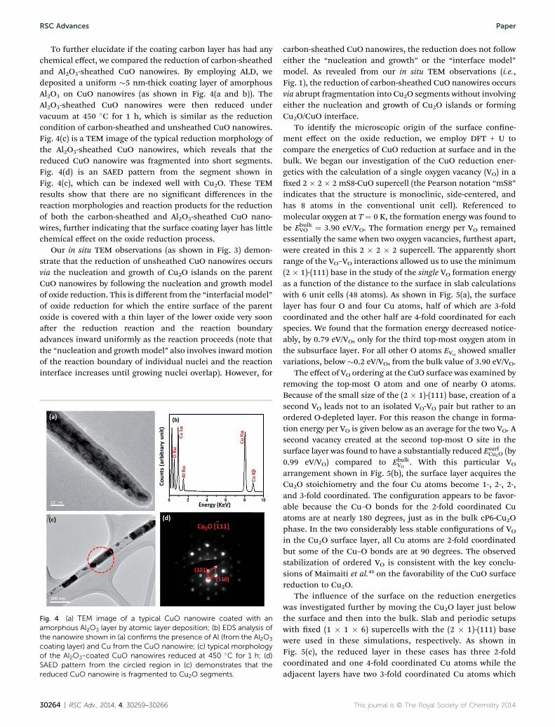
To further elucidate if the coating carbon layer has had anychemical effect, we compared the reduction of carbon-sheathedand Al2O3-sheathed CuO nanowires. By employing ALD, wedeposited a uniform �5 nm-thick coating layer of amorphousAl2O3 on CuO nanowires (as shown in Fig. 4(a and b)). TheAl2O3-sheathed CuO nanowires were then reduced undervacuum at 450 �C for 1 h, which is similar as the reductioncondition of carbon-sheathed and unsheathed CuO nanowires.Fig. 4(c) is a TEM image of the typical reduction morphology ofthe Al2O3-sheathed CuO nanowires, which reveals that thereduced CuO nanowire was fragmented into short segments.Fig. 4(d) is an SAED pattern from the segment shown inFig. 4(c), which can be indexed well with Cu2O. These TEMresults show that there are no signicant differences in thereaction morphologies and reaction products for the reductionof both the carbon-sheathed and Al2O3-sheathed CuO nano-wires, further indicating that the surface coating layer has littlechemical effect on the oxide reduction process.
Our in situ TEM observations (as shown in Fig. 3) demon-strate that the reduction of unsheathed CuO nanowires occursvia the nucleation and growth of Cu2O islands on the parentCuO nanowires by following the nucleation and growth modelof oxide reduction. This is different from the “interfacial model”of oxide reduction for which the entire surface of the parentoxide is covered with a thin layer of the lower oxide very soonaer the reduction reaction and the reaction boundaryadvances inward uniformly as the reaction proceeds (note thatthe “nucleation and growthmodel” also involves inwardmotionof the reaction boundary of individual nuclei and the reactioninterface increases until growing nuclei overlap). However, for
Fig. 4 (a) TEM image of a typical CuO nanowire coated with anamorphous Al2O3 layer by atomic layer deposition; (b) EDS analysis ofthe nanowire shown in (a) confirms the presence of Al (from the Al2O3
coating layer) and Cu from the CuO nanowire; (c) typical morphologyof the Al2O3-coated CuO nanowires reduced at 450 �C for 1 h; (d)SAED pattern from the circled region in (c) demonstrates that thereduced CuO nanowire is fragmented to Cu2O segments.
30264 | RSC Adv., 2014, 4, 30259–30266
carbon-sheathed CuO nanowires, the reduction does not followeither the “nucleation and growth” or the “interface model”model. As revealed from our in situ TEM observations (i.e.,Fig. 1), the reduction of carbon-sheathed CuO nanowires occursvia abrupt fragmentation into Cu2O segments without involvingeither the nucleation and growth of Cu2O islands or formingCu2O/CuO interface.
To identify the microscopic origin of the surface conne-ment effect on the oxide reduction, we employ DFT + U tocompare the energetics of CuO reduction at surface and in thebulk. We began our investigation of the CuO reduction ener-getics with the calculation of a single oxygen vacancy (VO) in axed 2 � 2 � 2 mS8-CuO supercell (the Pearson notation “mS8”indicates that the structure is monoclinic, side-centered, andhas 8 atoms in the conventional unit cell). Referenced tomolecular oxygen at T ¼ 0 K, the formation energy was found tobe EbulkVO ¼ 3.90 eV/VO. The formation energy per VO remainedessentially the same when two oxygen vacancies, furthest apart,were created in this 2 � 2 � 2 supercell. The apparently shortrange of the VO–VO interactions allowed us to use the minimum(2 � 1)-(111) base in the study of the single VO formation energyas a function of the distance to the surface in slab calculationswith 6 unit cells (48 atoms). As shown in Fig. 5(a), the surfacelayer has four O and four Cu atoms, half of which are 3-foldcoordinated and the other half are 4-fold coordinated for eachspecies. We found that the formation energy decreased notice-ably, by 0.79 eV/VO, only for the third top-most oxygen atom inthe subsurface layer. For all other O atoms EVO
showed smallervariations, below �0.2 eV/VO, from the bulk value of 3.90 eV/VO.
The effect of VO ordering at the CuO surface was examined byremoving the top-most O atom and one of nearby O atoms.Because of the small size of the (2 � 1)-(111) base, creation of asecond VO leads not to an isolated VO-VO pair but rather to anordered O-depleted layer. For this reason the change in forma-tion energy per VO is given below as an average for the two VO. Asecond vacancy created at the second top-most O site in thesurface layer was found to have a substantially reduced Esurf
Cu2O (by0.99 eV/VO) compared to Ebulk
VO. With this particular VO
arrangement shown in Fig. 5(b), the surface layer acquires theCu2O stoichiometry and the four Cu atoms become 1-, 2-, 2-,and 3-fold coordinated. The conguration appears to be favor-able because the Cu–O bonds for the 2-fold coordinated Cuatoms are at nearly 180 degrees, just as in the bulk cP6-Cu2Ophase. In the two considerably less stable congurations of VO
in the Cu2O surface layer, all Cu atoms are 2-fold coordinatedbut some of the Cu–O bonds are at 90 degrees. The observedstabilization of ordered VO is consistent with the key conclu-sions of Maimaiti et al.42 on the favorability of the CuO surfacereduction to Cu2O.
The inuence of the surface on the reduction energeticswas investigated further by moving the Cu2O layer just belowthe surface and then into the bulk. Slab and periodic setupswith xed (1 � 1 � 6) supercells with the (2 � 1)-(111) basewere used in these simulations, respectively. As shown inFig. 5(c), the reduced layer in these cases has three 2-foldcoordinated and one 4-fold coordinated Cu atoms while theadjacent layers have two 3-fold coordinated Cu atoms which
This journal is © The Royal Society of Chemistry 2014

Fig. 5 Simulated CuO structures with the fixed (111) base: (a) a slab with stoichiometric O-terminated surfaces; (b) a single Cu2O layer at thesurface of CuO; (c) a single Cu2O layer in the bulk of CuO. The surface and bulk simulations with (1� 1� 6) (111) CuO supercells were performedin the slab and periodic setups, respectively. For (b) and (c), the shown Cu2O and adjacent layers are doubled in the lateral directions to illustratethe VO ordering pattern. The small black spheres are O vacancies, themedium red spheres are O atoms, and the large grey spheres are Cu atoms.The shades of grey illustrate the coordination of the Cu atoms: from 1-fold (lightest) to 4-fold (darkest).
Paper RSC Advances
results in EsubsurfCu2O � Ebulk
VO¼ �1:27 eV=VO and Ebulk
Cu2O � EbulkVO
¼�0:96 eV=VO. Creation of oxygen vacancies in the bulk isexpected to induce local stress due to the slightly smallermeasured volume of Cu4O2 (77.8 A3)55 compared to that ofCu4O4 (81.0 A
3).56 Our DFT + U calculations at T¼ 0 K showed acomparable volume ratio of 78.9 A3/83.3 A3 for the two phases.To isolate the effect of the structural constraint we repeatedthe bulk calculations allowing the supercell to relax fully andobserved only a small change from – 0.96 to�1.00 eV/VO in therelative formation energy of the Cu2O layer. Comparison ofthese values to the one obtained for the surface,EsurfCu2O � Ebulk
VO¼ �0:99 eV=VO, reveals that the CuO reduction
proceeds more easily for layers (i) with the starting 4-foldcoordination of Cu and O atoms and (ii) near the surface wherethe O-depleted congurations are able to relieve stress.
These DFT calculations corroborate well with our experi-mental observations on the unsheathed CuO nanowires forwhich the surface reduction is more favorable than the bulkreduction because of the smaller oxygen vacancy formationenergy. The previously investigated ordering of surface oxygenvacancies resulting in Cu2O formation near the CuO surface42 isconsistent with the experimentally observed Cu2O nucleationand growth on the nanowire surface. The illustrated strongtendency of VO to order in the bulk as well as at the surfacesuggests that Cu2O nucleation may occur in carbon-sheathedCuO nanowires with the presence of substantial amounts ofbulk VO.
4. Conclusion
In summary, we performed a comparative in situ heating TEMstudy of the thermally induced reduction of CuO nanowireswith and without a carbon shell. We nd that carbon-sheathedCuO nanowires are reduced to Cu2O by the fragmentation of the
This journal is © The Royal Society of Chemistry 2014
starting CuO nanowire into Cu2O segments encapsulated by thecarbon shell, while unsheathed CuO nanowires are reduced toCu2O with the nucleation and growth of Cu2O bulges on thenanowire surface. We show that their difference originates fromthe carbon shell surface connement effect that changes thereaction mechanism from surface reduction via nucleation andgrowth of 3D Cu2O islands on the nanowire surface to theinternal reduction. One of the possible reduction mechanismsin the bulk, corroborated with our DFT calculations, is viaordering of oxygen vacancies in the bulk which can lead tonanowire fragmentation into CuO segments.
Acknowledgements
This work was supported by the National Science Foundationunder NSF CAREER Award Grant CMMI-1056611.
References
1 V. E. Henrich and P. A. Cox, The surface science of metaloxides. Cambridge University Press, Cambridge, 1994.
2 H. H. Kung, Transition metal oxides: surface chemistry andcatalysis, Elsevier, New York, 1989.
3 C. H. Bamford, C. F. H. Tipper, R. G. Compton,Comprehensive Chemical Kinetics, Elsevier, New York, 1984,vol. 21.
4 S. R. Zhang, J. J. Shan, Y. Zhu, L. Nguyen, W. X. Huang,H. Yoshida, S. Takeda and F. Tao, Nano Lett., 2013, 13,3310–3314.
5 R. D. L. Smith, M. S. Prevot, R. D. Fagan, S. Trudel andC. P. Berlinguette, J. Am. Chem. Soc., 2013, 135(31), 11580–11586.
6 S. D. Senanayake, D. Stacchiola and J. A. Rodriguez, Acc.Chem. Res., 2013, 46(8), 1702–1711.
RSC Adv., 2014, 4, 30259–30266 | 30265

RSC Advances Paper
7 D. Gamarra, A. Lopez Camara, M. Monte, S. B. Rasmussen,L. E. Chinchilla, A. B. Hungria, G. Munuera, N. Gyorffy,Z. Schay, V. C. Corberan, J. C. Conesa and A. Martinez-Arias, Appl. Catal., B, 2013, 130–131, 224–238.
8 K. Morita, K. Sakuma, K. Miyajima and F. Mafune, J. Phys.Chem. A, 2013, 117(40), 10145–10150.
9 R. Baghi, G. R. Peterson and L. J. Hope-Weeks, J. Mater.Chem. A, 2013, 1, 10898–10902.
10 Y. Z. Hu, R. Sharangpani and S. P. Tay, J. Electrochem. Soc.,2001, 148(12), G669–G675.
11 S. Y. Lee, N. Mettlach, N. Nguyen, Y. M. Sun and J. M. White,Appl. Surf. Sci., 2003, 206, 102–109.
12 R. Govindaraj, C. S. Sundar and R. Kesavamoorthy, J. Appl.Phys., 2006, 100, 084318.
13 F. Irrera, G. Puzzilli and D. Caputo, Microelectron. Reliab.,2005, 45, 853–856.
14 J. Li, J. Mayer and K. Tu, Phys. Rev. B: Condens. Matter Mater.Phys., 1992, 45(10), 5683–5686.
15 J. Y. Kim, J. A. Rodriguez, J. C. Hanson, A. I. Frenkel andP. L. Lee, J. Am. Chem. Soc., 2003, 125, 10684–10692.
16 J. A. Rodriguez, J. C. Hanson, A. I. Frenkel, J. Y. Kim andM. Perez, J. Am. Chem. Soc., 2002, 124(2), 346–354.
17 J. J. Scholz and M. A. Langell, Surf. Sci., 1985, 164(2–3), 543–557.
18 R. Furstenau, G. McDougall and M. Langell, Surf. Sci., 1985,150(1), 55–79.
19 B. Delmon, in Handbook of Heterogeneous Catalysis, ed. G.Ertl, H. Knozinger andJ. Weitkamp, Wiley-VCH, New York,1997, pp. 264–277.
20 J. A. Rodriguez, J. Y. Kim, J. C. Hanson, M. Perez andA. I. Frenkel, Catal. Lett., 2003, 85(3–4), 247–254.
21 X. Q. Wang, J. C. Hanson, A. I. Frenkel, J. Y. Kim andJ. A. Rodrigues, J. Phys. Chem. B, 2004, 108, 13667–13673.
22 T. Ressler, R. E. Jento, J. Wienold, M. M. Gunter andO. Timpe, J. Phys. Chem. B, 2000, 104, 6360–6370.
23 J. Pike, S. W. Chan, F. Zhang, X. Q. Wang and J. Hanson,Appl. Catal., A, 2006, 303, 273–277.
24 G. W. Zhou and J. C. Yang, Phys. Rev. Lett., 2004, 93, 226101.25 G. W. Zhou, W. Y. Dai and J. C. Yang, Phys. Rev. B: Condens.
Matter Mater. Phys., 2008, 77(24), 245427.26 Y. Qin, S. M. Lee, A. L. Pan, U. Gosele and M. Knez, Nano
Lett., 2008, 8(1), 114–118.27 L. Li and G. W. Zhou, Surf. Sci., 2011, 605, 54–61.28 L. Yuan, Q. Yin, Y. Wang and G. Zhou, Chem. Phys. Lett.,
2013, 590, 92–96.29 Y. Li, Q. Fu and M. Flytzani-Stephanopoulos, Appl. Catal., B,
2000, 27(3), 179–191.30 C. Ammon, A. Bayer, G. Held, B. Richer, L. Schmidt and
H. Steinruck, Surf. Sci., 2002, 507, 845–850.31 C. T. Campbell and K. A. Daube, J. Catal., 1987, 104(1), 109–
119.32 T. Tabakova, V. Idakiev, J. Papavasiliou, G. Avgouropoulos
and T. Loannides, Catal. Commun., 2007, 8(1), 101–106.
30266 | RSC Adv., 2014, 4, 30259–30266
33 I. Nakamura, H. Nakano, T. Fujitani, T. Uchijima andJ. Nakamura, J. Vac. Sci. Technol., A, 1999, 17(4), 1592–1595.
34 X. Q. Wang, J. A. Rodriguez, J. C. Hanson, D. Gamarra,A. Martinez-Arias and M. Fernandez-Garcia, J. Phys. Chem.B, 2005, 109(42), 19595–19603.
35 L. Yuan and G. W. Zhou, J. Electrochem. Soc., 2012, 159,C205–C209.
36 R. Mema, L. Yuan, Q. Du, Y. Wang and G. W. Zhou, Chem.Phys. Lett., 2011, 512(1–3), 87–91.
37 L. Yuan, Y. Q. Wang, R. Mema and G. W. Zhou, Acta Mater.,2011, 59, 2491–2500.
38 W. Ding, D. Dikin, X. Chen, R. Piner, R. Ruoff, E. Zussman,X. Wang and X. Li, J. Appl. Phys., 2005, 98(1), 014905.
39 E. Sutter, P. Sutter and Y. Zhu, Nano Lett., 2005, 5(10), 2092–2096.
40 V. C. Holmberg, M. G. Panthani and B. A. Korgel, Science,2009, 326(5951), 405–407.
41 L. Y. Isseroff and E. A. Carter, Chem. Mater., 2013, 25(3), 253–265.
42 Y. Maimaiti, M. Nolan and S. D. Elliott, Phys. Chem. Chem.Phys., 2014, 16, 3036–3046.
43 V. I. Anisimov, J. Zaanen and O. K. Andersen, Phys. Rev. B:Condens. Matter Mater. Phys., 1991, 44(3), 943.
44 J. Heyd, G. E. Scuseria and M. Ernzerhof, J. Chem. Phys.,2006, 124(21), 9906.
45 J. P. Perdew, K. Burke and M. Ernzerhof, Phys. Rev. Lett.,1996, 77(18), 3865–3868.
46 D. Wu, Q. Zhang and M. Tao, Phys. Rev. B: Condens. MatterMater. Phys., 2006, 73(23), 235206.
47 M. Heinemann, B. Eifert and C. Heiliger, Phys. Rev. B:Condens. Matter Mater. Phys., 2013, 87(11), 115111.
48 J. Hu, D. Li, J. G. Lu and R. Wu, J. Phys. Chem. C, 2010,114(40), 17120–17126.
49 M.-F. Yu, O. Lourie, M. J. Dyer, K. Moloni, T. F. Kelly andR. S. Ruoff, Science, 2000, 287(5453), 637–640.
50 D. N. Madsen, K. Mølhave, R. Mateiu, A. M. Rasmussen,M. Brorson, C. J. Jacobsen and P. Bøggild, Nano Lett., 2003,3(1), 47–49.
51 A. Martinez-Garcia, V. K. Vendra, S. Sunkara, P. Haldankar,J. Jasinski and M. K. Sunkara, J. Mater. Chem. A, 2013, 1,15235–15241.
52 L. F. Shen, H. S. Li, E. Uchaker, X. G. Zhang and G. Z. Cai,Nano Lett., 2012, 12(11), 5673–5678.
53 C. Marichy, M. Bechelany and N. Pinna, Adv. Mater., 2012,24, 1017–1032.
54 S. Carenco, C. Surcin, M. Morcrette, D. Larcher, N. Mezailles,C. Boissiere and C. Sanchez, Chem. Mater., 2012, 24(4), 688–697.
55 S. Hafner and S. Nagel, Phys. Chem. Miner., 1983, 9(1), 19–22.
56 S. Asbrink and L.-J. Norrby, Acta Crystallogr., Sect. B: Struct.Crystallogr. Cryst. Chem., 1970, 26(1), 8–15.
This journal is © The Royal Society of Chemistry 2014