r.s.v.p. lunar habitats - spacearchitect.org · crew members for 24 to 28 weeks without resupply....
TRANSCRIPT

R.S.V.P. LUNAR HABITATS
Self-Landing Mobile Lunar Habitat
Jonathan ReyesSaneil Suri
William Vanden DriesPhillip Watters
ASE 274L / 174MSeptember 21, 2005
Submitted to Dr. Wallace Fowler
The Department of Aerospace Engineering and Engineering MechanicsThe University of Texas at Austin

i
Executive Summary
The possibility of a base on the moon has been discussed for several decades and thereare myriad of reasons for which a lunar base would be beneficial. For example, a lunarbase would be an advantageous research and testing facility for hardware eventually usedon a Mars mission. A great deal of research on lunar habitats has already been done overthe past few decades.
The need statement calls for a modular lunar habitat which will be able to support 3-4crew members for 24 to 28 weeks without resupply. The habitat must be able to beassembled and operated without a crew for a couple of years. The habitat will containonly crucial systems and will serve as a building block for a much larger habitat withseveral modules and will eventually be self-sufficient.
The habitat will be self sufficient and will include a main living quarters, a node, and anairlock. The habitat will be operational upon crew occupation. As with any spaceexploration mission, there are several inherent risks involved and safety is important.Robustness of design is important in order to reduce the risk to acceptable levels.
The mission is divided into four main categories: Habitat Design/Fabrication, SitePreparation, Mission Delivery, and Habitat Deployment. The habitat design portion isbroken up into external and internal design. The external habitat design includes thestructure and shielding while the internal design involves creating the module layout andnecessary module systems. The shielding is a key part of the structure and must dealwith thermal, micro-meteor, and radiation hazards. The internal design will addressEnvironmental Control and Life Support Systems, communication systems, as well asergonomic issues of the habitat layout. Site preparation includes the landing site choiceand teleoperating robots to prepare the site. The delivery portion will involve theresearch into the launch vehicle, trans-lunar trajectories,mass and propellant schedules,and a lander. The deployment will entail teleoperation and module assembly andintegration. The assembly sequence will be planned out in detail, and a method ofconnecting additional modules will be designed.
The estimated cost of the research and design part of this mission is estimated to be$45,000. This cost includes engineering man-hours as well as computer hardware andmodeling cost. The estimated cost of building the hardware is about 1.875 billion dollars.


iii
Table of Contents1 Introduction .............................................................................................................1
1.1 Project Motivation............................................................................................11.2 Mission Heritage ..............................................................................................11.3 Need Statement ................................................................................................11.4 Mission Overview ............................................................................................21.5 Risk Evaluation................................................................................................21.6 Assumptions ....................................................................................................3
2 Technical Summary .................................................................................................42.1 Base Requirements...........................................................................................42.2 Revised Habitat with Integrated Design............................................................4
2.2.1 Habitat Structural Design..........................................................................42.2.2 Habitat Modules .....................................................................................102.2.3 Module Systems .....................................................................................172.2.4 Module Layout .......................................................................................242.2.5 Other Considerations ..............................................................................31
2.3 Site Preparation..............................................................................................322.3.1 Habitat Landing Site Selection Guidelines..............................................322.3.2 Rail Mobility and Habitat Assembly.......................................................33
2.4 Mission Delivery............................................................................................342.4.1 Trajectory...............................................................................................352.4.2 Mass and Propellant Schedules...............................................................362.4.3 Launch Vehicle ......................................................................................372.4.4 Landers ..................................................................................................38
2.5 Habitat Deployment .......................................................................................422.5.1 Teleoperation .........................................................................................422.5.2 Module Deployment from Lander...........................................................422.5.3 Regolith Shield.......................................................................................432.5.4 Power Connection ..................................................................................442.5.5 Common Berthing Mechanisms..............................................................46
3 Management Proposal............................................................................................483.1 Project Hierarchy ...........................................................................................483.2 Work Flow Chart ...........................................................................................493.3 Project Deliverables .......................................................................................50
4 Cost Proposal.........................................................................................................514.1 Design and Production Costs..........................................................................514.2 Personnel Costs..............................................................................................51
5 Strengths/Weaknesses............................................................................................525.1 Major Strengths..............................................................................................525.2 Major Weaknesses .........................................................................................52
6 References .............................................................................................................53

iv
List of FiguresFigure 1: Solid Core Design.............................................................................................5Figure 2: Module Core Prior to Inflation..........................................................................6Figure 3: Module after Inflation.......................................................................................6Figure 4: Regolith "Tent" Shield Design..........................................................................8Figure 5: Conventional Micrometeorite Shielding [8] ......................................................9Figure 6: Inflatable Shielding [9] .....................................................................................9Figure 7: Goldised Kapton Multi-Layer Insulation Blanket [8] .....................................10Figure 8: Main Living Quarters .....................................................................................11Figure 9: Sectioned View of Main Living Quarters........................................................12Figure 10: Airlock .........................................................................................................13Figure 11: Sectioned View of Airlock............................................................................13Figure 12: Node Module with Basic Dimensions ...........................................................14Figure 13: Sectioned View of Node: ..............................................................................15Figure 14: Multi-Purpose Logistics and Escape Module ................................................16Figure 15: Sectioned View of Multi-Purpose Logistics and Escape Module...................16Figure 16. Power Systems Breakdown. [8] ....................................................................17Figure 17: ECLS Subsystem Interfaces [8] ....................................................................18Figure 18: Example of System Racks.[26] .....................................................................24Figure 19: Rack Layout .................................................................................................25Figure 20: Main Living Quarters Layout........................................................................26Figure 21: Layout of Operational Areas .........................................................................27Figure 22. Hohmann Transfer Trajectory. ......................................................................35Figure 23. Launch Timeline...........................................................................................38Figure 24. Model of External Structure of Main Living Quarters Prior to Inflation. .......40Figure 25. Lander Structure and Module External Structure (Shown Separately). ..........40Figure 26. Lander and Payload (Shown Mated). ............................................................41Figure 27. Lander Design for Solid Core Modules. [4]...................................................41Figure 28. Teleoperation in Progress..............................................................................42Figure 29. Pre-Designed Lunar Truck. [7]......................................................................43Figure 30. Power Mouse Design. ...................................................................................45Figure 31. Connector Box for Mouse. ............................................................................45Figure 32. Power Station with Connector Boxes. ...........................................................46Figure 33. The Passive and Active Halves of the Common Berthing Mechanism. [8] ....47Figure 34. Project Hierarchy. .........................................................................................48Figure 35. Flow Chart Showing Work Breakdown. [21] ...............................................49
List of TablesTable 1. Velocity Changes Needed for Lunar Mission. ..................................................36Table 2. Dry Masses of Modules/Lander.......................................................................36Table 3. Mass Schedule for the Main Module. ...............................................................37Table 4. Mass Schedule for Airlock. ..............................................................................37Table 5. Mass Schedule for Node. .................................................................................37Table 6. Project Deliverables and Due Dates..................................................................50Table 7: Production Costs .............................................................................................51Table 8. Estimated Costs................................................................................................51

1
1 Introduction
1.1 Project Motivation
The advantages of having a habitat on the moon include the possibilities of extended
research of lunar surfaces and lunar materials, research into the effects of sub-Earth
gravity for extended periods of time on plants and animals, and being able to study the
stars without the Earth’s atmosphere in the way. Hopefully in the process, the existing
habitation technologies will progress and open up the possibility of setting up a habitat on
Mars. In addition to enhancing habitation technologies, a lunar base would serve as an
ideal launching point for future manned missions to Mars and beyond.
Enclosed habitats have already been designed for extreme conditions in places such as
Antarctica. This project will be studying these pre-existing habitats along with the
International Space Station technologies to design a suitable lunar habitat.
1.2 Mission Heritage
The Apollo missions and the International Space Station contributed greatly in the design
of the lunar habitat. Technologies from these missions as well as other space exploration
missions were taken into account. For example, the Apollo mission trajectories will be
used in this mission. Information about the lunar environment also stems from research
from the Apollo era. The International Space Station also had a large impact as well.
The modular design of ISS was incorporated into the lunar habitat. ISS taught us quite a
few lessons about long-term human occupation in the reduced gravity, vacuum
environment of space. Through ISS, we learned a lot about integrating large systems and
program management.
1.3 Need Statement
The lunar base shall be independently operable for 24 to 28 weeks without any major
resupply. It must be able to be remain unoccupied for 2 years. The design proposed will
be modular, with separate launches used for each module. These modules will be
designed with the possibility of expansion in mind.

2
1.4 Mission Overview
This project proposes to safely land and to teleoperate the assembly of a multi-element
lunar base. This multi element base will serve as the foundation for a future, self-
sufficient habitat which is not in the scope of this project.
The site must be prepared and the habitat must be assembled without human presence.
The habitat will also be able to autonomous link up with the previously landed solar
power station. Once assembled, the habitat must be able to go into an idle power
consumption mode for up to 2 years until a three to four person crew arrives. Upon crew
arrival, the habitat must be operational and be able to function without resupply for 24 to
28 weeks. Comfortable living conditions must be maintained until the operational
lifetime of the habitat is over. Required accommodations include sleeping spaces, a
kitchen and dining area, a workroom, an ECLSS and a communications system, a
micrometeorite and solar radiation shielding, and an airlock. Internal atmospheric
composition, temperature, humidity, and pressure must be maintained at comfortable
levels during periods of crew occupation.
The module and lander will be launched into a Low Earth Oribt (LEO) by a booster
which will be designed at a later time. Mass and propellant schedule are laid out
according to the selected the Translunar trajectory. The lander will deliver the habitat to
the landing site and soft land on the lunar surface.
1.5 Risk Evaluation
The first risk the project must face is the failure to successfully launch the module landers
into space and the failure to safely land the module Landers within the specified distance
of the construction site. If they do not land close enough, they may not be able to travel
over the lunar terrain to the site, or they may not pick up the landing site homing beacon
at all.
The most important risk is the risk to the crew that will be living in the habitat. The crew
will be depending on technology to protect them from the harsh environment of space.
Every aspect of the missions should be at least two-fault tolerant, and critical aspects

3
should be three-fault tolerant. Two important risk that need to be addressed are solar
radiation and bone mass loss. Astronauts that have traveled in space or stayed on the
International Space Station (ISS) have never been exposed to solar radiation for the
amounts of time this project is proposing. Bone mass loss is also a threat to astronauts in
sub-Earth gravity for extended periods of time. That is why it is extremely important to
plan for the effects of space travel or living as well as the effects of solar radiation.
Public safety must also be taken into account. It is important to minimize the risk that a
launch failure will harm the public, or that hazardous materials will return to earth.
Long-term Earth and Moon environmental risks exist as well. [25]
1.6 Assumptions
The following assumptions are made for this report:
1. The Solar Power Station has been launched, is fully operational, and is located in thepolar region. It also must be able to provide the necessary power to the habitat.2. Landing Beacons will already be in place at landing sites. They will have been placedon a previous mission to select a landing site.3. The teleoperated landscaping and construction robots will already be in place at theselected landing site.4. The scope of this proposal begins after the landing site has been prepped and readiedfor habitat delivery.5. The power station will be the first component of the habitat to arrive at the site.6. A Boeing Delta IV Heavy derivative will be available to launch the modules/landerspayload to a LEO7. NASA will develop a machine to collect regolith and dump it into the regolith tent8. Inflatable core technology will be space certified

4
2 Technical Summary
2.1 Base Requirements
The posed need statement requires that the robotic lunar habitat meet certain
requirements for living conditions and set-up procedures. The base must be ready to
sustain life before any life has actually set foot on the moon. The base must provide for
food, water, power, climate control, and other such necessities. Power supply systems are
out of the scope of this project and will be addressed by another design team. Food,
water, and other supplies will be regularly supplied by launches containing food and
water rations. A main goal of this project is to minimize the need for resupply launches
and develop as much autonomy as possible. Water and climate control will be regulated
throughout the base.
2.2 Revised Habitat with Integrated Design
After advice from the chief consultant, the team decided that a cylindrical design would
be best for the habitat. This resulted in a new concept for the lunar habitat.
2.2.1 Habitat Structural Design
The habitat will consist of several different parts that will come together to form the
entire structure for the base.
2.2.1.1 Structure
The new main structure of the base went through two different phases. The original plan
was to have a solid core made out of aluminum. The design then became an inflatable
core which would allow for increased space and lighter liftoff mass.
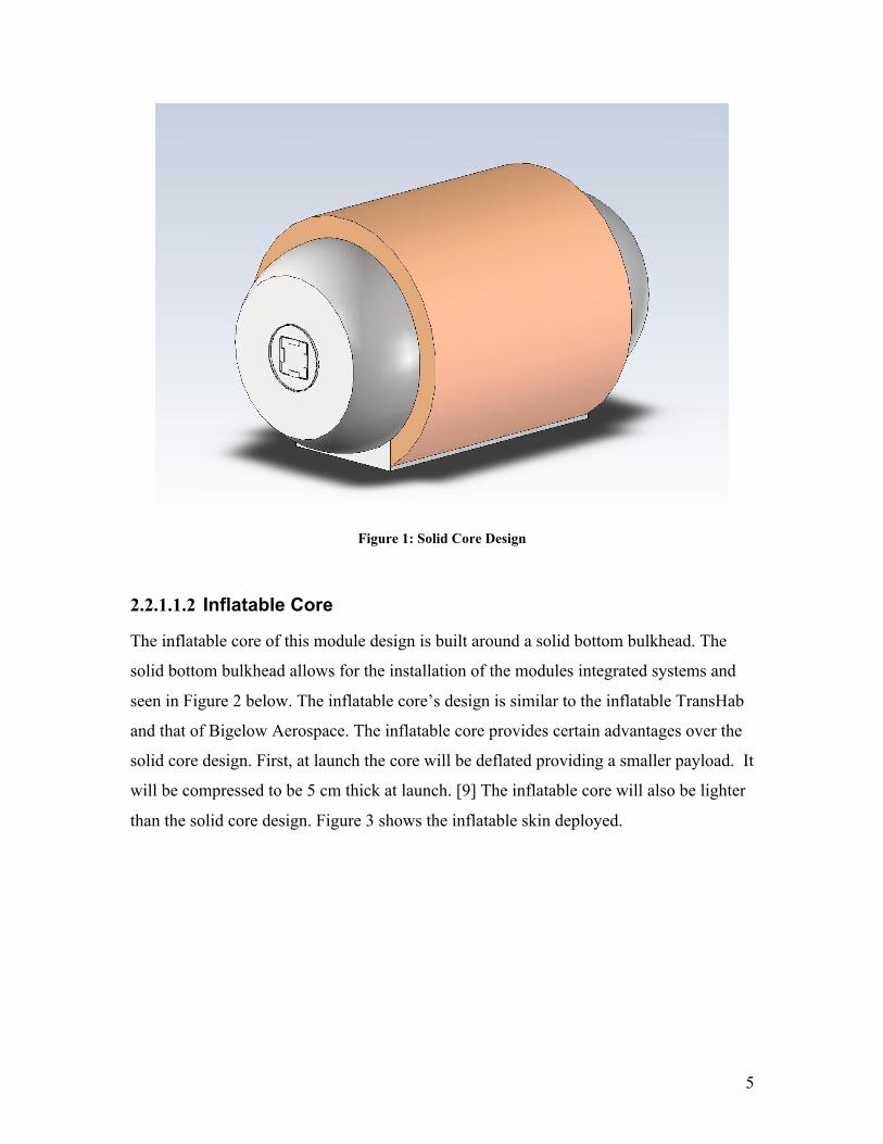
2.2.1.1.1 Solid Core
The solid core of this module design is based on the hard shell of the ISS. It will be made
of aluminum. The benefit to a solid core is that it is more rigid and may better protect the
systems with in during launch. The solid core can have inflatable shielding. Figure 1
shows the solid core design.
5
Figure 1: Solid Core Design
2.2.1.1.2 Inflatable Core
The inflatable core of this module design is built around a solid bottom bulkhead. The
solid bottom bulkhead allows for the installation of the modules integrated systems and
seen in Figure 2 below. The inflatable core’s design is similar to the inflatable TransHab
and that of Bigelow Aerospace. The inflatable core provides certain advantages over the
solid core design. First, at launch the core will be deflated providing a smaller payload. It
will be compressed to be 5 cm thick at launch. [9] The inflatable core will also be lighter
than the solid core design. Figure 3 shows the inflatable skin deployed.

6
Figure 2: Module Core Prior to Inflation
Figure 3: Module after Inflation

7
The skin of the inflatable core, like the TransHab's skin, will be made of material that
deflects projectiles. The core will be one-foot-thick shell composed of 12 different layers
that are designed to have small space debris break upon impact. The outer shell is made
of Kevlar webbing rated to withstand 12,500 pounds. The layers underneath are made out
of Nextel, a ceramic fabric. The Nextel layers also serve to protect the crew from
temperatures from 250 degrees Fahrenheit to minus 200 degrees Fahrenheit. [10]
2.2.1.2 Shielding
The moon’s environment requires that certain precautions be taken to protect the crew
from dangers not normally faced in Low Earth Orbit missions.
2.2.1.2.1 Radiation
Radiation is a major safety concern for lunar habitation and long-term space travel.
Lunar radiation is caused by the bombardment of galactic cosmic rays GCRs) and solar
energetic particles (SEPs). Radiation exposure on the lunar surface is much greater than
the radiation exposure onboard the International Space Station (ISS) because the ISS still
has the protection of the Earth’s magnetic field. In addition to the primary radiation from
GCRs and SEPs, secondary radiation is produced when cosmic rays hit the lunar surface.
Possible health risks associated with space radiation are cancer, cataracts, acute radiation
sickness, detrimental hereditary effects, and damage to the central nervous system. In
addition to the substantial health risks, radiation could possibly affect electrical
equipment performance as well. [11]
Successful lunar habitation depends on adequately shielding flight crews and equipment
from the effects of galactic cosmic rays and solar energetic particles. Current radiation
shielding practices utilized in the ISS and the Shuttle are not enough to protect flight
crews and equipment from GCRs and SEPs. Current estimates indicate that shielding
would have to be increased from 5 g/cm2 to greater that 20 g/cm2. This increase would
drastically increase the mass of vehicles and payloads with a lunar destination.
Radiation shielding utilizes lunar regolith as a shield. Current estimates require a shield
of regolith one meter thick. A structure made out of Kevlar and supported by a truss

8
system will serve as a “tent” to hold the regolith. Kevlar is thermally stable up to 800°F
to 900°F (427°C to 482°C). [22] The tent will be a semicircle with an inner radius of 7
meters and external radius of 8 meters. This provides a meter of regolith to shield the
habitat. This regolith shield will be deployed prior to the arrival of the crew and even the
modules. There is on average 3.5” (0.0889m) of loose regolith on the lunar surface. The
volume of the regolith shield is approximately 1744m. With a packing factor of two,
approximately 10 football fields would have to be scraped of regolith to fill the shield.
Figure 4 shows the Regolith “Tent” Shield.
Figure 4: Regolith "Tent" Shield Design
2.2.1.2.2 Micrometeorite
Micrometeorite shielding is also an import component of habitat shielding. Conventional
aluminum micrometeorite shielding causes debris to break into small fragments that is
distributed over a larger area reducing the impact and is seen below in Figure 5.[8] The
micrometeorite shielding on the inflatable core model utilizes the same method of
dispersing the energy over a larger area, but uses different material. The inflatable shield
utilizes Kevlar and Nextel to disperse the energy of debris impact and can absorb 12,500
pounds as shown in Figure 6. [10]

9
The micrometeorite shielding discussed above will be part of the habitat structure and
should provide secondary protection against debris impacts. The primary source of
micrometeorite shielding will be the regolith shield discussed above.
Figure 5: Conventional Micrometeorite Shielding [8]
Figure 6: Inflatable Shielding [9]

10
2.2.1.2.3 Thermal
Thermal shielding will be taken care of by the many layers that the base will already have
in place. The regolith shield, already in place, will help maintain a constant temperature
immediately outside the base. The micrometeorite shielding will also provide a layer of
thermal protection. As stated before, the Nextel layers in the inflatable shield also serve
to protect the crew from temperatures from 250°F (121°C) to minus 200°F (-129°C). [10]
In conjunction with those layers, a 3mm to 7mm thick Goldised Kapton Multi-Layer
Insulation blanket as seen in Figure 7, will be located below the micrometeorite shield in
order to maintain an internal temperature between 10°C and 20°C. [23]
Figure 7: Goldised Kapton Multi-Layer Insulation Blanket [8]
2.2.2 Habitat Modules
The habitat will consist of the following modules:
• Main Living Quarters• Airlock

11
• Node• Multipurpose Escape Module
2.2.2.1 Main Living Quarters
The main living quarters, as the name implies, is where the crew will conduct most of
their daily routines (Figure 8 and Figure 9). The module will have places for storage,
sleep and every day objectives. The sleeping quarters will be above the main
compartment. There will be ladders for the crew to reach their beds. Below the floor of
the main compartment will be a place for all of the habitat systems racks to be stored.
This will be described in later sections. In the main compartment, there will be a
communications station, dining area, and work area. Again, these areas will be further
described in later sections.
Figure 8: Main Living Quarters

12
Figure 9: Sectioned View of Main Living Quarters
The main living quarters will be around 12 meters long and the interior will be 4.7 meters
at its widest point wide and floor width of 4m. The design provides for one meter of
headroom in the sleeping compartments that are located above the main compartment.
This module will be spacious enough to house the three to four crew members
comfortably, with room to conduct their every day lives.
2.2.2.2 Airlock
The airlock (Figure 10 and Figure 11) will be used as a means to exit the habitat safely.
It will have a solid core. The airlock dimensions will be 6 meters long and an interior
radius of 4.7m. The airlock will have enough space to store three space suits as well as
additional space for storing food, water, or anything else.

13
Figure 10: Airlock
Figure 11: Sectioned View of Airlock

14
2.2.2.3 Node
The node module (Figure 12 and Figure 13) will serve as a means of expansion for the
base. Like the main living quarters, the node will have an inflatable core. It will be
similar in shape to the main living quarters and will be 6m long, 4.7m at its widest point,
and have a floor width of 4m, but will house four berthing mechanisms instead of the two
that every other module has. This will help in constructing the base in a lateral direction
if it is necessary. The node will not only serve as a means of connection and expansion,
but it will also contain storage space. It, like the airlock, will have compartments above
and below the main compartment that could be used to store whatever is necessary.
Figure 12: Node Module with Basic Dimensions

15
Figure 13: Sectioned View of Node:
2.2.2.4 Multipurpose Logistic and Escape Module
The Multipurpose Logistic and Escape Module (MLEM) will be added to the habitat
when the crew arrives. The MLEM (Figure 14 and Figure 15) will serve as the main
form of transportation between the habitat and Earth. The MLEM will function as a
combined the Soyuz/Progress /Multi Purpose Logistics Module (MPLM) for the habitat.
The MLEM will contain all the food and water required for the duration of the mission as
well as spare parts. It will also serve as an escape craft if needed. When a new crew
arrives, they will do so in their own MLEM, which will replace the old one that will be
returning the old crew back to Earth. The Multipurpose Logistic Module will be 6m long
and have an interior radius of 4.7m.

16
Figure 14: Multi-Purpose Logistics and Escape Module
Figure 15: Sectioned View of Multi-Purpose Logistics and Escape Module

17
2.2.3 Module Systems
The following sections will describe the systems that will facilitate the operation of the
habitat and the survival of the crew.
2.2.3.1 Power System
The power system will be responsible for providing power to all electrical systems
including lighting, communications, life support, and command and control. The power
consumption of the habitat is estimated using the ISS power consumption. The ISS and
this habitat requires between 90 kilowatts to 150 kilowatts of total power be delivered
from the power plant. [13]
The power that is supplied by the power plant is considered primary power. Primary
power (high voltage power) is approximately equal to 160 V dc. [8] Primary power will
be brought into the habitat via insulated cables. The Main Living Module will have two
power insertion points to provide power redundancy.
Secondary voltage power is what powers all the electrical systems on board the habitat.
The onboard electrical systems require that the 160 V dc obtained from the power plant
be reduced to approximately 124 V dc. [8] Secondary voltage is distributed throughout
the habitat via a network of power distribution assemblies. The power system is
illustrated below in Figure 16.
Figure 16. Power Systems Breakdown. [8]

18
2.2.3.2 Environmental Control and Life Support System
With the lack of lunar atmosphere, Environmental Control and Life Support (ECLS)
systems is an essential component for crew survival. The ECLS System provides and
regulates habitat atmosphere and resources necessary to sustain life and comfortable
living and working conditions. Figure 17 below shows the interrelation between the
ECLS subsystems and the cabin atmosphere. Because of the isolation of the lunar base, a
Regenerative ECLS system is ideal to conserve resources. The Regenerative ECLS
systems utilized within the lunar base will serve as a test bed for future Mar’s habitats.
Figure 17: ECLS Subsystem Interfaces [8]
2.2.3.2.1 Atmosphere Control and Supply
Crewmembers aboard the base will require atmospheric conditions similar to Earth. The
Atmosphere Control and Supply (ACS) system provides the oxygen and nitrogen
necessary to maintain the Module pressure at 14.7 psi and atmosphere composition of
21% oxygen, 78% nitrogen, and 1% other. Nitrogen and oxygen tanks located outside
the habitat module will maintain cabin atmosphere. Nitrogen will solely be stored in the
external tanks and will need to be recharged or replaced when emptied. In addition to the

19
external oxygen tanks, oxygen will be created using an Oxygen Generator (OG). The OG
will make oxygen by splitting water into hydrogen and oxygen (electrolysis). [14]
Electrolysis is not efficient with respect to power consumption, but it is still necessary to
have a system in place. If power becomes an issue, the crew can solely use the external
oxygen tanks for breathable air. During this initial phase of the lunar habitat there will
not be room to have plants produce oxygen.
Oxygen production will be regenerative ECLS because there will also be a Sabatier
present. The Sabatier will produce water by utilizing the hydrogen from the OG and
carbon dioxide obtained from the Atmosphere Revitalization Subsystem. Solid fuel
oxygen generators (candles) will also be present if additional oxygen is required.
The atmospheric conditions of the lunar habitat will be maintained through the use of a
Pressure Control Assembly (PCA). The PCA’s function is to monitor atmospheric
pressures, control the introduction of nitrogen and oxygen into the cabin atmosphere from
the external tanks, and depressurize the lunar habitat if necessary. [15]
As new modules are added to the habitat and Extra Vehicular Activities (EVA) are
performed, the atmospheric pressure within the habitat will have to be equalized. ACS
also provides pressure equalization valves between modules of the lunar habitat.
2.2.3.2.2 Atmosphere Revitalization
The ACS subsystem controls the atmosphere composition and pressure on the base. The
Atmosphere Revitalization (AR) subsystem is charged with the monitoring and removal
of harmful gases form the atmosphere.
Crew members produce Carbon Dioxide through respiration which needs to be removed
in order to maintain a livable atmosphere. The removal and venting of CO2 from the
atmosphere will be provided for by two methods. The primary system will be unit with a
series of beds made of a special metal oxide sorbent that will absorb CO2 and vent it to
space. Lithium hydroxide (LiOH) canisters will be used as secondary system to remove
CO2 from the atmosphere. The LiOH absorbs the CO2. [16]

20
Trace amounts of contaminants due to equipment off gassing and other metabolic
processes must also be removed from the atmosphere. A Trace Contaminant Control
System will perform this function.
2.2.3.2.3 Temperature and Humidity Control
The Temperature and Humidity Control (THC) system provides air movement for crew
comfort, air filtration, temperature selectivity, and humidity control. The temperature
selectivity will range from 65 to 85 degrees Fahrenheit and the humidity will be
maintained within 40 to 60 percent.
There will be three levels of air circulation within the habitat. They are rack,
intramodule, and intermodule ventilation. Rack ventilation will circulate and cool air
within racks where equipment is located. Intramodule ventilation controls the
atmosphere within a single module. Intramodule ventilation will be controlled by a
Common Cabin Air Assembly (CCAA), which contains a fan and a condensing heat
exchanger. High Efficiency Particulate Air (HEPA) filters will remove particles from the
air stream before air enters the CCAA. The CCAA will also control humidity by
removing moisture from the atmosphere when water is condensed as air passes over the
cold heat exchanger. The condensed moisture will be sent to a condensate tank to be
collected and recycled. Intermodule ventilation controls the atmosphere of the entire
habitat by circulating air between modules. Intermodule ventilation will be maintained
through the use a series of fans and valves that circulate air between modules using a
ducting system. [8]
2.2.3.2.4 Water Recovery and Management
Water, after air, is the most important element aboard the lunar habitat. The Water
Recovery and Management (WRM) system will collect, recycle, and distribute water
throughout the habitat. The WRM system will include the condensate tank used by THC.
In addition to the condensate tank, the WRM will also include a Urine Processor and a
Potable Water Processor. The Urine Processor will separate water from urine and refine

21
it to waste water. The Potable Water Processor will process waste water collected
throughout the habitat into potable water.
2.2.3.2.5 Fire Detection and Suppression
There exists a real possibility of fires occurring within the habitat. Fires, especially on a
remote base on the moon, can result in a loss of life, the end of the mission, or can affect
systems functionality. In order for a fire to occur there must be three elements: an
ignition source, a fuel source, and oxygen. This is a major reason that pure oxygen is not
used inside the cabin. Since it is difficult to eliminate the use of oxygen and because
electronics and wiring are a common ignition source, the materials used must be chosen
such that they do not burn under the expected atmospheric conditions or they are “self-
extinguishing”. In the occurrence of a fire, the fire detection and suppression subsystem
must be able to detect smoke, warn the crew of a fire event, provide automatic and
manual isolation and suppression, and remove harmful atmospheric constituents.
Smoke detectors will be distributed throughout the habitat in order to detect fires. These
smoke detectors may use photoelectric diodes to measure light intensity and scatter of a
laser in order to estimate the amount of particles in the air. A problem with this type of
smoke detector is that it does not differentiate what types of particles are in the
atmosphere. Since there is gravity on the Moon, there is possibility that conventional
smoke detectors can be used.
In the event of a fire an audible alarm as well as accompany light system will alert the
crew of a potential fire. Onboard software will isolate electrical ignition sources and will
isolate the module/s where the smoke detector was tripped. To fight the fires manually,
crewmembers will be equipped with Halon 1211 fire extinguishers and an oxygen mask.
Use of any type of personal fire extinguisher poses a threat to crew health, but is
necessary for overall crew and mission safety. If the fire does not expire by itself and can
not be put out manually, the module will be isolated and will vent all the gas to space via
the vacuum system. This will extinguish the fire. After the fire has been extinguished,
the module is repressurized.

22
2.2.3.2.6 Vacuum System
The habitat will have vents in various locations to access the vacuum of space. These
vents are valuable and have a variety of uses. The vacuum system will be used to vent
unwanted off-gassing, CO2, and other gases to space. It will also be used to vent entire
modules in case of fires that put the crew or habitat in jeopardy. Lastly, it will be used to
provide any science payloads access to a vacuum if needed. Leakage is a major concern
with this system. A leak in this system would cause the atmosphere to leak out of the
atmosphere and into space.
2.2.3.3 Communication
Continuous communication between the Earth and Moon are needed so that astronauts
can communicate with mission control on Earth. The communication system within the
module must be operational before any crew is sent to the moon and should be
operational early in the sequence to remotely control the base assembly. The distance
between the Earth and Moon will create a time lag of approximately 1.5 seconds.
Continuous, direct communications with dark side of the moon are not feasible; however,
in all likelihood, a manned lunar habitat would be located on the near side of the moon.
Since the probable location of a lunar base would be on the near side of the moon close to
one of the poles, it is also difficult to have direct continuous communication between the
Earth and the moon because of the moon’s 18.5° to 28.5° inclination with respect to the
Earth’s equator. It becomes evident that an intermediary relay would be useful.
The most likely solution will be to use a communications hub between the habitat and
Earth to establish constant communication. The communication relay will be positioned
at 85° S latitude on the near side of the moon. This will allow continuous communication
between the lunar habitat and Earth. [17]
Direct communication between to objects on the moon (e.g., between the habitat and a
rover) becomes unfeasible at 30km due the small size of the moon and large rate of
curvature. This also makes direct communication with the communication relay located
at 85° S latitude unfeasible. [19] Every degree of latitude on the moon corresponds to
approximately 30km based on a polar equator of diameter 3472km. Therefore, the direct

23
communications problem could be overcome by using a series of five communication
relays placed at 89° S, 88° S, 87° S, 86° S, and 85° S.
The communication system will consist of an internal audio subsystem, an S-band
subsystem, a Ultrahigh Frequency (UHF) subsystem, and a Ku-band subsystem. The
internal audio subsystem distributes audio onboard the habitat. The S-band subsystem
transmits voice, commands, telemetry, and files. The Ku-band subsystem will transfer
commands and data between the habitat and Mission Control. The UHF subsystem is
used for Lunar Surface Missions. [8]
2.2.3.4 Command and Control
The Command and Control system (CCS) is the brain of the habitat. The CCS will be
responsible for collecting data from all of the habitats systems and payloads, process
data, and sends commands to appropriate equipment. The CCS will provide the crew
with habitat level control. The CCS will also be in continuous communication with
Mission Control, who will also have habitat level control. [8] All of the subsystem
sensors will be in constant communication with the CCS so that onboard telemetry will
be continuously sent to Mission Control.
The crew will access the CCS via crew interface computers. There will be two crew
interface computers in the Main Living Quarters, and one crew interface computer in
each of the other habitat modules. The crew interface computers will be laptops.
Laptops are more versatile than hardwired systems because they are portable,
interchangeable, and upgradeable.
A key feature of the CCS will be the Caution and Warning Alerts. These alerts will
notify the crew of any situations that are off nominal. The CCS will grade all off nominal
events according to set criterion and alert the crew appropriately. Caution and warning
alerts will be both visual and audible in nature.

24
2.2.4 Module Layout
This section covers the layout and placement of internal systems of the Main Living
Quarters. The general layout of the operations areas within the Main Living Quarters
will also be discussed.
2.2.4.1 Integration of Systems
The initial design of the lunar habitat had each major system housed in its own module.
It was decided that a module with integrated systems would be more beneficial.
Integrated systems allow the Main Living Quarters module to be stand-alone. When the
lunar habitat is expanded the Main Living Quarters module will be able to support the
crew if any emergency occurs and the station has to be sealed off.
The Systems Racks as seen in Figure 18 will be housed within the bulkhead of the floor.
This provides a stable platform for the racks. The floor paneling will be removable so
that the crew may work on or install new racks. There will be a compartment to store
food and water rations in addition the rack housings. The majority of the electrical
wiring and all of the air and water plumbing will be housed in the floor as well.
Figure 18: Example of System Racks.[26]
Figure 19 shows the proposed layout of the systems racks and access to the electrical and
plumbing conduit. Also seen in Figure 19 are possible positions of stowage cabinets that
are also part of the solid bottom bulkhead.

25
Figure 19: Rack Layout
In addition to the Main Living Quarters module having all the systems needed to operate
the habitat, each of the other modules will contain essential systems racks necessary to
survive, if the Main Living Quarters is damaged. The systems incorporated into the
additional modules will be sufficient to provide the crew time to repair the damage or
escape the habitat.
2.2.4.2 Layout of Operations Areas
The Main Living Quarters will be divided into Areas of Operations. This is done so that
there is additional structure to the module. It will provide a feeling of separate rooms as
opposed to living in an efficiency apartment. Work areas will be separate from recreation
and dining areas. The Areas of operations will be separated using partitions that will be

26
removable and modifiable. This gives the crew the option to modify their living
arrangements.
Figure 20: Main Living Quarters Layout
and Figure 21 below show the general layout of the areas of operations. Each individual
area has yet to be designed and will be added as it is completed. Ergonomics will play a
role in the design of each area of operation.
1.8 6m.
1.45m.
1.45m.
0.92m.
1.45m.
0.90m.
1.04m.
0.76m.
0.60m.
0.46m.
0.70m.
4.0
0m
.
0 .5
0 m.
1.07m.
12m.
Galley/Food Stowage
Dining
Exercise
ShowerBath
Work Area/Communication/
Command
Health /Safety
Stowage
Stowage Stowage
Figure 20: Main Living Quarters Layout

27
Figure 21: Layout of Operational Areas
2.2.4.3 Module Ergonomics
Ergonomics is an applied science concerned with designing and arranging things people
use so that the people and things interact most efficiently and safely. Module ergonomics
for the lunar habitat will be unique in that lunar gravity is one-sixth of Earth’s gravity.
Lunar habitat furniture and layout will be specially designed to accommodate for the
reduced gravity. Furniture and storage space will be important considerations for module
ergonomics because of the presence of gravity just as they were special considerations
onboard the International Space Station because of the lack of gravity.
In addition to the reduced gravity ergonomic concerns, conventional ergonomic concerns
will also be addressed. Lighting, temperature, noise, vibrations, and humidity also affect
working efficiency and state of mind. These aspects will also be addressed. [20]

28
2.2.4.3.1 Bathroom/Shower
The Lunar Habitat Module is essentially a 4-person bunkroom. According to Sanitary
Fixture Requirements, a study completed by the U.S, Navy, 4-person bunkroom requires
two washbasins, one toilet, zero urinals, and one shower. [24, p. 333] The shower, toilet,
and two sinks will be separated by partitions so that the use of one fixture does not hinder
the use of the other fixtures.
The shower dimensions will be 36” (91cm) wide, 57” (145cm) long (including 15”
(38cm) for a seat), and 84” (213cm) tall. The shower will have a seat, a handrail, a
toiletry and soap shelf, and both a fixed and a flexible showerhead. A seat is included so
that the crew may safely clean their feet. The seat will be 15” (38cm) high. The handrail
will be 37” (94cm) off the floor. The soap shelf will be 45” (114cm) off the floor. The
showerheads will be 78” (198cm) off the floor, and the fixed showerhead will protrude 8”
(20cm) from the shower wall. In addition, the shower controls will be accessible from
both outside and inside the shower. The shower drain is to be located at the far end of the
unit so that the user will not have to step in it. In order to save space, the shower door
will slide open. Within the shower compartment there will also need to be 36” (91cm)
between the shower door and the compartment entry. This will allow room for disrobing
and changing. [24, p. 333]
The toilet will be 18” (46cm) high. There will be a clearance of 18” (46cm) from the
wall to the center of the toilet to the sidewalls of compartment. There will be a 30”
(76cm) clearance from the front of the toilet to the wall. [24, p. 333]
The two sinks will be located between the shower and toilet compartments. There will be
36” (91cm) between the shower and toilet compartments. The sinks will be offset from
one another and located on opposite walls. The top of the sink will be 30” (76cm) high
and have a spill proof lip along its edge. There should be 18” (46cm) of clearance from
the center of the sink out toward to the sides. [24, p. 333]
2.2.4.3.2 Galley

29
The galley will contain storage for food and drinks (dehydrated), a hydrator, a sink, a
microwave or force-air convection oven, and a trash compactor. The counter tops of the
galley will have spill lips to prevent liquids from spilling over the edge. The galley
cabinets will prevent spilled liquids from dripping into electrical wiring. Galley cabinets
will also have no sharp edges or corner where crewmembers could possibly injure
themselves. Galley lighting will be of high quality. [24, p. 354]
2.2.4.3.3 Dining Area
The dining area will allow crewmembers to eat meals together in a comfortable setting.
The dining area will consist of a table that is integrated into the module wall and chairs
for each of the crewmembers. The dining chairs will be approximately 17” (43cm) high.
The seat will have a fore-aft slope of 5°, and the angle between the seat back and the seat
will be 105°. The seat length is also approximately 17” (43cm). For comfort, there are
optimum relations between the chair and the dining table. The maximum distance
between the tabletop and the seat of the chair is 12” (30.5cm). There is also a minimum
distance of 7” between the seat and the bottom of the table to allow for adequate leg
clearance. The table will allow for comfortable eating. The table will have the
dimensions of 36” (91cm) wide, 80” (203cm) long, and approximately 29” (74cm) high.
This allows for adequate spacing between the crewmembers. The table size allows there
to be 12” (30.5cm) spacing between chairs and give the crew a 24” (61cm) table-setting
envelope. There will also be a lip around the table to prevent any spills from falling to the
floor. This will protect the equipment racks beneath the crew’s feet. [24, p. 357]
2.2.4.3.4 Sleeping Quarters
The crew sleeping quarters will be integrated into the area above the Main Living
Quarters. The sleeping quarters will be individual bunk quarters and are modeled after
U.S. Navy ship berths (beds). Navy standards dictate that beds should be at least 84”
(213cm) long, 36” (91cm) wide, and at least 32” (81cm) of vertical clearance. The crew
sleeping quarters will have the dimensions of 150” (381cm) long, 80” (203cm) wide, and
40” (101cm) of vertical clearance. The increased size of the bunks allows each
crewmember their own personal space isolated from the everyday sights and sounds of
the Main Quarters. The increased size also allows for more storage space of personal

30
belongings. Each bunk will have its own lighting, controllable ventilation, sound system
that allows the crew to listen to music, communicate with other bunks, and alerts the
crew of any dangers. [24, p. 339]
2.2.4.3.5 Work Area
The work area will provide the crew with an area to monitor and control habitat systems
and communicate with Earth. The work area will include four laptops (one for each
crewmember) and a communications center. The work area will consist of a workbench
that will be 140” (356cm) long, 24” (61cm) wide, and 39” (99cm) high. This
configuration allows for sit-stand operations. The workbench will have seating integrated
into them so that the stools will be pulled out from the workbench area. The integrated
stools will be 30” (76cm) high with a foot rest located 17” (43cm) below the seat of the
stool. [24, p. 383]
2.2.4.3.6 Maintenance Workplaces
Since most of the equipment and systems’ racks are located beneath the floor,
maintenance interface design is important. The floor will have removable panels to allow
access to the racks. The racks will all be equipped with slide-out chassis to allow access
to all sides of the rack. [24, p. 393]
2.2.4.3.7 Temperature
Temperature effects human performance. The temperature within the habitat will be
maintained between 65 and 85 degrees Fahrenheit, and the humidity will be maintained
between 40 and 60 percent. Human physiology is slightly different for each person and
this is why there is a range on the temperature selectivity. Generally, 64°F is the lower
limit for acceptable motor coordination; 80°F is the maximum temperature for acceptable
performance, and 90°F is the upper limit for continued occupancy over any reasonable
period. [24, p. 816]
2.2.4.3.8 Color
Since the crewmembers will be spending extensive amounts of time within the habitat,
the color of the habitat’s interior is important. There are four basic psychological
responses to color. Color effects the perception of size of space, temperature, and mood

31
including taste and odor. Usually dark colors are perceived as advancing toward the
observer making a space look smaller, and light colors are perceived as receding away,
making the space seem larger. Colors can also make a space seem cooler or warmer.
Colors have a definite effect on mood. For example some colors are stimulating while
others are calming.
The dining area will be a yellowish-orange, which invokes a feeling of warmth,
excitement, comfort, and is associated with pleasing taste. The bathroom/shower areas
will be light green in color. Light green invokes feelings of coolness, comfortableness,
calmness, and is associated with refreshing odor. The sleeping chambers will be a light
blue color. . Light blue invokes feelings of coolness, comfortableness, calmness, and of
protection. The lightness of the color will make the sleeping quarters seem roomier than
it is. The work area will be a reddish-orange color. Reddish-orange invokes a feeling of
warmth, stimulation, excitement, comfort, and is associated with taste. The orange colors
used also make people appear healthy and normal. The orange colors are also more
advancing, but this is acceptable because of the size of the Main Living Quarters size.
[24, p. 836]
2.2.4.3.9 Noise
Noise refers to unwanted sounds. Noise level does affect performance ability. 40dB is
the recommended upper limit for quiet living spaces. 60dB is the upper limit for spaces
used for dining and social conversations, and 70dB is the upper limit for conversations.
At 100dB there is a serious reduction in alertness. [24, p. 846]
2.2.5 Other Considerations
2.2.5.1 Food/Water
Food and potable water for the crew will be supplied from Earth via supply drops. The
crew will be completely reliant on supply drops for food until hydroponics are introduced
to the habitat and food production becomes feasible. The food provided in the supply
drops, similar to food onboard the ISS, will be frozen, dehydrated, or heat stabilized.
Daily food intake will provide 3500 calories per crewmember. [25] Since there is gravity
on the moon, the crew will be able to indulge in the occasional carbonated beverage.

32
Although water will be conserved and recycled, the crew will also be reliant on water
supplied from Earth. Each crewmember will be allotted 5.16kg of drinking water per
day. [25] A possible water source on the lunar surface is ice trapped in craters located
about the poles of the moon.
2.2.5.2 Waste Removal
The solid waste collected from the habitat will be disposed of outside the module and
dumped at a certain location on the lunar surface. Possibly in the future a furnace will be
installed on the lunar surface to dispose of the waste.
2.2.5.3 Exercise
Regular exercise will be necessary for the crew to maintain their health and strength.
There will be exercise machine available for crew use. The initial exercise machine will
be storable and versatile to save space. A possible exercise machine is the bike/rowing
machine being designed at the University of Texas at Austin.
2.2.5.4 Medical Supplies
The habitat will also contain medical equipment for the crew to use. The medical kit will
include a first aid kit, field surgeon’s kit, stretcher, various medicines and a defribulator.
2.2.5.5 Entertainment
The crew will also be supplied with personal items to serve as recreation during non-
working hours. Personal items will include a personal DVD player, DVDs, music player,
portable game system, and books stored on disc.
2.3 Site Preparation
2.3.1 Habitat Landing Site Selection Guidelines
The lunar power plant that will be sent to the moon ahead of the lunar habitat is of crucial
importance to the success of the lunar habitat mission. If the lunar habitat does not
successfully land close enough to the lunar power plant to be easily transported to the
lunar base site, the mission will have a slim chance of success overall. As of right now,
the lunar power plant will land in or near the Shackleton Crater near the south pole of the

33
moon. The crater is located at 89.9o south and 0o east, and has a rim passing through the
south pole of the moon.
Another good reason for landing near the south pole of the moon is the relative lack of
extreme temperature ranges. As opposed to the temperatures at the lunar equator, where
the temperatures can have a range of more than 250K per lunar day, the Shackleton
Crater region should stay near a constant 220K. [5]
Because the moon’s axial tilt is not nearly as pronounced as the Earth’s, the sun does not
climb very high in the moon’s polar skies during a lunar day. The sun only moves about
1.5o over the course of an entire lunar year when seen from the lunar poles. This is why
the rim of the Shackleton Crater supposedly receives sunlight more than 80 % of the year,
and there are regions around the crater that collectively receive sunlight more than 98%
of the year. Because the sun doesn’t travel very far in the sky, some parts of the craters
have been in permanent shadow for millions of years [6]. This is why ice has been able to
form and remain in some of the depths of the craters located at the lunar poles. The build-
up of ice could provide the lunar habitat with water for the astronauts and possibly
provide fuel for spacecraft as well.
A large area of the crater must be prepared for the arrival of the power plant and lunar
habitat. The most important thing for the habitat and other future components of the lunar
base is the relative flatness of the lunar surface in the chosen base area. While provisions
such as module tracking are being designed, the more flat the surface is in the crater, the
easier the assembly of the lunar base will be. This flattening of the lunar surface inside of
the crater will most likely be done by a teleoperated robot with the capability of moving
regolith around. The design of this robot is not within the scope of this project and will be
left up to a future group to design. If a robot cannot be designed to harvest regolith and
flatted the lunar surface, explosives could be used instead.
2.3.2 Rail Mobility and Habitat Assembly
After the lunar habitat is removed from the lunar lander and is transported to the lunar
base site, it will be place on a pre-constructed track system to move into its final position.

34
Using railroad tracks greatly reduces the difficulty of assembling the modules, while also
providing an easy way of reconfiguring the modules around the lunar base.
The previous design of the assembly process for the lunar modules consisted of hydraulic
suspensions along with laser emitters and receptors to line up the CBMs on the modules.
Using the railroad track design relieves the need of any of these. Once the tracks are laid
down on the flattened regolith surface, even if the surface is not perfectly flat, the tracks
will still allow the modules to line up just like railroad cars stack behind a locomotive
engine. Preset stops will be implemented along the tracks at certain points to assure the
simplicity of mating certain modules.
The preliminary track width is 3 meters. This should provide the habitat modules with
enough support to move easily around the base. The design of the layout of the lunar base
tracks must also be designed, but it is not within the scope of this report. The tracks
should also provide the lunar trucks with easy access to an entry/exit port to the track
system, as well as an easy way of moving the modules around the base in case certain
modules need to be transported to different areas of the base.
2.4 Mission Delivery
Getting to the moon has proven to be a difficult task throughout the history of the space
program. The dangers posed to human lives during launch and during habitat
construction create the need for unmanned missions. For this reason, it is desirable to
create an autonomous lunar habitat that will be operational before a crew arrives. This
will allow for a base to be in place without people’s lives being put in danger during each
launch.
The design calls for a Main Living Module, an Airlock, a Node, and several
Multipurpose Logistics and Escape Modules (MLEMs) to be delivered to the moon. The
design team determined that multiple launches will be take place in order to deliver the
different modules. The main module will require one launch, and it is yet to be
determined if the Airlock and Node modules will be launched together or separately. The
MLEMs will be launched periodically and will deliver a new crew and supplies. Once the

35
modules have landed on the lunar surface the mission delivery phase is over, and the
habitat deployment stage will begin.
2.4.1 Trajectory
The trajectories used for the mission will be based on the Apollo trajectories. First, a
launch vehicle will deliver the modules into a low earth orbit (LEO) with an altitude of
184km. From the LEO, a burn will take place to put the module into a transfer orbit to the
moon. This orbit should be nearly a Hohmann Transfer. This orbit should place the
landers just ahead of the moon. Next, another delta v will allow the payload to move into
a circular polar orbit around the moon. This parking orbit needs to be polar orbit because
the landing site is on the South Pole. From the 100km polar parking orbit, the lander will
be deployed and navigate to the landing site. The velocity components upon touchdown
will be no greater than 0.5 m/s in the vertical and 0.25 m/s in the horizontal.
These trajectories will be used for all the modules and possibly the MLEM. The Apollo
trajectory minimizes fuel without creating long flight duration. The one-way trip should
take about 5 days. It also allows for a free-return trajectory to Earth in case of emergency.
Figure 22 shows the stages of the mission trajectories. Table 1 shows the delta V’s for the
Apollo missions. It also shows Hohmann transfer delta v’s for comparison [2]. The boost
to LEO and powered landing phases should be roughly the same no matter what type of
lunar transfer is used. The translunar injection and lunar orbit injection are similar for the
Hohmann and Apollo trajectories [3].
Figure 22. Hohmann Transfer Trajectory.

36
Table 1. Velocity Changes Needed for Lunar Mission.
Apollo Missions delta V (m/s) Hohmann delta V (m/s)
Boost to LEO (Delta IV) 9450 -
TransLunar Injection 3050 3150
Mid-course corrections 46 -
Lunar Orbit Insertion 914 850
Descent/Land 2150 -
2.4.2 Mass and Propellant Schedules
Table 2 shows the dry mass estimates of the modules and their respective landers that
will be delivered to the moon. The mass estimates are based on initial volume
calculations and expected densities. Table 3, Table 4, and Table 5 show the mass
schedule for the Main Living Quarters, Airlock, and Node. The final dry mass delivered
to the moon and the mass of the payload delivered to a LEO are highlighted for each
module. The Main Living Quarters is the largest module needed to be delivered. The
mass delivered to the moon will be around 22,000 kg. Consequently, almost 100,000 kg
will need to be delivered to a Low Earth Orbit (LEO). The Airlock and Node are
considerably less massive than the Main Module, so the launch vehicle must be able to
lift up to 100,000 kg to a LEO of 184 km. As a comparison, the Saturn V rocket
launched over 100,00 kg to a LEO.
During the Trans-Lunar stages, a chemical rocket with liquid hydrogen and liquid oxygen
will be used for propulsion. This offers a specific impulse of about 465 seconds, but
produces hydrofluoric acid as an exhaust product. Therefore, for the powered descent
stage, hydrocarbon liquid fuel will be used [27].
Table 2. Dry Masses of Modules/Lander.

37
Table 3. Mass Schedule for the Main Module.
Table 4. Mass Schedule for Airlock.
Table 5. Mass Schedule for Node.
2.4.3 Launch Vehicle
The launch vehicles chosen to carry the modules to the moon are the Boeing Delta rocket
and its derivatives. Utilizing existing launch technology will minimize research and
development costs significantly. The Delta rockets are proven and reliable launch
vehicles, especially when compared to a new launch vehicle that would have to be
designed, developed and tested.
The Delta IV Heavy was chosen because of its size and carrying capabilities. With slight
modifications to the payload compartment size, the Delta IV Heavy will be the best fit for
the Main Living Module. The Delta IV Heavy will also be used for the Airlock/Node

38
launch. The past success of the Boeing Delta IV added to the choice of this launch
vehicle. The standard Boeing Delta IV is capable of lifting 25 metric tons into a 407 km
orbit. With the desired modifications to the standard Heavy, a Heavy derivative would be
able to launch up to 95 metric tons to 407 km orbits. According to Boeing, a Heavy
derivative could be modified to carry a payload up to 6.5 m in diameter and 19.8 m in
length. The modules will be launched with their respective landers attached. [1]
The size and mass of the MLEMs is still to be determined, but a Delta IV Heavy will
probably provide sufficient lifting capability. [1]
Figure 23 shows the launch timeline. Two years will be used to prepare the landing site
and such. Then, the first three modules can be launched every six months, with an
additional year after the Node launches to install the regolith shield and get the habitat
ready. After that MLEMs with a new crew and supplies can be launched every six
months.
Figure 23. Launch Timeline.
2.4.4 Landers
The powered landing stage will begin once the lander and its payload are in a polar orbit
around the moon. The lander will leave the lunar orbit and will navigate to the base site
using the landing beacons that must already be in position prior to the launching of the
modules. The lander should then be able to drop the module. Once the cargo from the
lander has been dropped module deployment begins, which is discussed in detail in later
sections. After the cargo has been moved away from the lander, the lander will lift off

39
and will navigate to another beacon. This beacon will be placed close to the landing site
around 89 degrees latitude on the near side of the moon. The landers will be detach from
the modules, and then will be lifted off the module by the lunar truck, which will be
discussed in a later section.
After the module is detached, a Kevlar “pouch” will be attached to the landers such that it
will be able act as a dump truck to hold regolith. The lander will have wheels, and will
be used to collect regolith over large area and take it to the habitat. The regolith
collection is discussed in greater detail in a later section. After the lander has been used
for the regolith collection it will be used as a support structure to which the oxygen and
nitrogen tanks will be mated.[Fowler-consultant].
Figure 24 shows the External Structure of the Main Living Quarters prior to inflation.
The model will discussed further in a later section. Figure 25 and Figure 26 show the
Lander structure and how it mates to the Module. The Node lander(s) will also have
similar set ups because they will also have inflatable cores. The lander is such that the
center of gravity is low. This is prevent the module from tipping over upon landing.
Figure 27 is a possible lander design for the Airlock because of the solid core. The lander
for the MLEMs will be used as crew return/escape vehicles, so will be equipped to lift off
and return to the earth. The design of the MLEM module and lander is out of the scope of
this paper, and should be addressed in any future research.

40
Figure 24. Model of External Structure of Main Living Quarters Prior to Inflation.
Figure 25. Lander Structure and Module External Structure (Shown Separately).

41
Figure 26. Lander and Payload (Shown Mated).
Figure 27. Lander Design for Solid Core Modules. [4]

42
2.5 Habitat Deployment
2.5.1 Teleoperation
Teleoperation is the process of controlling a robotic system from a distance. Usually this
is done from a video signal sent from the robot back to the headquarters where a person
images the video signal and then controls the robot. For lunar missions, teleoperations is
preferable to autonomous operation because there is only a 1.28-second time lag for
communication between the moon and Earth. A visual example of teleoperation can be
seen in Figure 28.
Figure 28. Teleoperation in Progress.
2.5.2 Module Deployment from Lander
The habitat module will arrive on the surface of the moon attached to a lunar lander. The
module must be removed from the lunar lander and transported to the lunar base site.
This will be done using a modified “lunar truck” originally designed by a group of
students at the University of Texas at Austin in 1999. Two illustrations of their design
can be seen below in Figure 29.

43
Figure 29. Pre-Designed Lunar Truck. [7]
The lunar truck provides a stable transportation system for the module from the lander to
the lunar base.
Modifications to this lunar truck must be made in order to successfully carry out the
mission of the lunar habitat. The base that the habitat component sits on in Figure 29 will
be removed and the components will be hung from the overhead supports instead.
Another aspect of the lunar truck that must be designed is the capability of being solar
powered. Because the pole of the moon is expected to receive near constant sunlight, the
truck should have a combination of a solar powered energy system coupled with a backup
battery system.
Lastly, the lunar trucks must have cameras mounted on them in a way for teleoperation to
be carried out. Several cameras must also be placed around the lunar base site to help
with the insertion of the modules onto the tracks.
2.5.3 Regolith Shield
The regolith shield will be deployed as modules arrive one by one. Once the module has
been placed in the desired position, the empty Kevlar regolith tenth will be set up over
the module with a truss support system. The regolith itself will be collected from a large
area and placed in the converted lander-dump truck. Assuming an average depth of
0.089m for loose regolith and assuming a packing factor of 2, an area of 200m x 200m
will need to be excavated to fill the tent. This means about 10 football fields of regolith.
Since a bulldozer would not be efficient in the sub-gravity environment, a cork screw
mechanism will be used to collect loose regolith and lift it into the dump truck. The

44
dump truck filled with regolith will be moved to the habitat and the corkscrew
mechanism will transfer the regolith into the tent. The regolith collection and tent filling
procedures will be relatively slow. For this reason, the launch schedule is spread over a
few years.
2.5.4 Power Connection
Once the habitat reaches the lunar base site, it will need to connect with a power source to
begin the power-up and stabilization process. The lunar power plant will already be up
and running before the lunar habitat reaches the base site, therefore all that is needed is a
connection to the power plant.
The connection will be carried out using a teleoperated mouse that will travel from the
stationary lunar habitat to the functional power plant. This mouse will be attached to a
power cord capable of supplying enough power back to the base to run through all of the
start-up procedures. Once these have been carried out, another mouse will be deployed
from the habitat and connected to the power station to bring reserve power back to the
base. An illustration of a simple design of the mouse can be seen in Figure 30. The main
power connection is protected by a damage control tube. The damage control tube has a
pin slot connector to assure alignment with the female power connection at the power
station. The power cable has wheels attached to ease the transportation of it across the
lunar surface. The main mouse wheels as well as the power cable wheels have been
equipped with spikes for traction on the lunar surface.

45
Figure 30. Power Mouse Design.
A preliminary design of the connection between the mouse and the power station can be
seen in Figure 31. The mice will drive into the outlet box so a perfect connection on a flat
surface will be guaranteed. The pin connector that the mouse will drive up to must be
able to rotate so the connection can lock into place for protection against a surface
disturbance such as a meteorite impact causing disconnection. As seen in Figure 32 the
power station has the capability to support five power mice.
Figure 31. Connector Box for Mouse.

46
Figure 32. Power Station with Connector Boxes.
2.5.5 Common Berthing Mechanisms
Once the secondary modules (any module other than the central habitat module) reach the
construction site on the lunar surface, they will need some way to attach to another
desired module. This will be done using the Common Berthing Mechanism (CBM)
already in use on the International Space Station. The active and passive halves of the
CBM can be seen in Figure 33.

47
Figure 33. The Passive and Active Halves of the Common Berthing Mechanism. [8]
The active half is connected to the power supply while the passive half is not. Therefore
the active half of the CBM will have to be placed on the module that will already be
connected to the habitat assembly and the passive half will be mounted on the newest
addition to the construction site.
48
3 Management Proposal
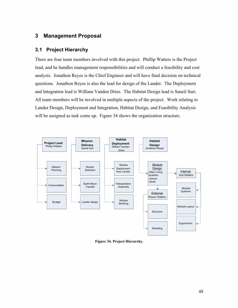
3.1 Project Hierarchy
There are four team members involved with this project. Phillip Watters is the Project
lead, and he handles management responsibilities and will conduct a feasibility and cost
analysis. Jonathon Reyes is the Chief Engineer and will have final decision on technical
questions. Jonathon Reyes is also the lead for design of the Lander. The Deployment
and Integration lead is William Vanden Dries. The Habitat Design lead is Saneil Suri.
All team members will be involved in multiple aspects of the project. Work relating to
Lander Design, Deployment and Integration, Habitat Design, and Feasibility Analysis
will be assigned as task come up. Figure 34 shows the organization structure.
Project LeadPhillip Watters
Mission DeliverySaneil Suri
Mission Planning
Budget Lander design
Earth /Moon Transfer
Habitat DeploymentWilliam Vanden
Dries
Module Berthing
Teleoperation Assembly
Habitat Design
Jonathan Reyes
Module Deployment from Lander
Consumables
Structure
Shielding
Rocket Selection
Module Design
-Main Living Quarters-Airlock-Node
Module Systems
ExternalReyes /Watters
InternalSuri/Watters
Module Layout
Ergonomics
Figure 34. Project Hierarchy.

49
3.2 Work Flow Chart
Figure 35 shows calls out important stages in the project and lays out a sequence of
events.
Mission Design
Preliminary Research
Proposal
Detailed Research
Preliminary Lander Design
Preliminary Deployment/Integ
ration schedule
Pre liminary Habitat Schedule
Midterm Report/Midterm Project Briefing
Midterm Project Evaluation/Direction
Final Research
Design Finalization
Secondary Project Design Evaluation
Final Mission Briefing
Final Design Evaluation
Final Written Report
Figure 35. Flow Chart Showing Work Breakdown. [21]

50
3.3 Project Deliverables
The design portion of the project will result in several analyses which will now be
discussed. First, the Lander will be analyzed. This includes GNC, Propulsion and
structure. Secondly, a plan for deployment and integration will be put forth. This will
include analyses of module deployment, robotic construction, assembly, and a plan for
integration. Lastly, a design of the lunar habitat and subsequent analyses will also be
delivered. The subtopics covered by the Lunar habitat will include ECLS, Structure,
Ergonomic/Layout, shielding, and maintenance. Table 6 shows project deliverables and
corresponding due dates.
Table 6. Project Deliverables and Due Dates.
Deliverables DateDesign Proposal 9-21-05Team Progress Reports WeeklyPowerpoint Poster 10-10-05Team Website 10-10-05Mid-semester Oral Presentation 10-14-05Mid-Semester Peer Evaluations 10-14-05Oral Final Presentation 12-2-05Written Final Presentation 12-9-05Design Synopsis 12-9-05Design Poster and Model 12-9-05End-of-Semester Peer Evaluations 12-9-05

51
4 Cost Proposal
4.1 Design and Production Costs
Table 7: Production Costs
4.2 Personnel Costs
Table 8. Estimated Costs.
Job Description Total Hours Hourly Rate ($ perhour)
Total Cost($)
Engineer TeamMembers
24,000 25 600,000
Module Teleoperator 1,000 20 20,000Bulldozer Teleoperator 1,000 20 20,000
The personnel costs come to a total of about $640,000.

52
5 Strengths/Weaknesses
5.1 Major Strengths
The major strengths of the habitat design are the utilization of space within modules,
modular design of habitat, the teleoperated assembly, and use of existing technologies.
The inflatable design of the main habitat increases the free volume within the volume.
This design allows the crew sleeping quarters to be located above the main compartment
and frees up valuable floor space for other functions. The modular design of the habitat
is major strength because it allows for easy base expansion. This design is only the first
step for the establishment of a lunar base. As the scope of the lunar mission changes and
grows, new modules will be attached to accommodate those changes. The teleoprated
assembly of the habitat is a major strength because it is cheaper and less difficult that
automated habitat assembly. For the lunar habitat, the teleoperated assembly will result
in a smaller probability that the equipment will be damaged during assembly. This
design is also heavily reliant on existing technologies. This allows more money to be
spent on the product as opposed to research. The reliability of these technologies have
been proven through thousands of hours of operation aboard the International Space
Station. For example the ECLS, communication, power, command and control
subsystems have been used to great success on the ISS.
5.2 Major Weaknesses
Two major weakness of this design is the implementation of the regolith shield and the
assumption that construction robots will be available. The regolith shield is a very large
structure that has to be deployed in conjunction with the module. Because of the amount
of regolith needed, the assembly time for the regolith shield will be timely. However,
since there is not a strict timetable for completion, there is time to collect and construct
the shield. This design relies heavily on the assumption that working construction robots
will be available to prepare the site and assemble the habitat.

53
6 References1. NASA, Guidelines and Capabilities for Designing Human Missions,
http://research.hq.nasa.gov/code_u/nra/current/NRA-02-OBPR-01/HSSWG.pdf,accessed December 7, 2005.
2. NASA, http://hitf.jsc.nasa.gov/hitfpub/analysis/mars1.html
3. Howstuffworks, How Inflatable Spacecraft Will Work,http://science.howstuffworks.com/inflatable-spacecraft2.htm, accessed 10/10/05.
4. NASA,http://www.nasa.gov/vision/space/travelinginspace/radiation_shielding.html,accessed 9/19/05.
5. DuPont,http://www2.dupont.com/Personal_Protection/en_US/assets/downloads/kevlar/la-underingguideforprotectiveapparel.pdf , accessed December 8, 2005.
6. NASA, International Space Station Familiarization,http://vesuvius.jsc.nasa.gov/er/seh/td9702.pdf, accessed 9/20/05.
7. ESA, Mars Express, http://bepicolombo.esa.int/science-e/www/object/doc.cfm?fobjectid=36464., accessed December 8, 2995.
8. NASA, http://spaceflight.nasa.gov/spacenews/reports/issreports/1999/iss99-15.html.
9. NASA,http://www.nasa.gov/centers/marshall/pdf/104840main_ECLSS%20Fact%20Sheet.pdf.
10. Boeing, Supporting Life on the International Space Station.http://www.boeing.com/news/releases/2001/q1/news_release_010205s.html,accessed on 9/17/05.
11. Howstuffworks, How Space Stations Work,http://science.howstuffworks.com/space-station.htm, accessed 9/10/05.
12. http://www.space.com/missionlaunches/moon_southpole_030604.html.
13. www.astronautix.com/craft/lesrbase.htm.
14. NASA, http://stationpayloads.jsc.nasa.gov/ images/e3_3.jpg, accessed December6,2005.
15. Cornell University,http://ergo.human.cornell.edu/Conferences/EECE_IEQ%20and%20Productivity_ABBR.pdf.

54
16. Woodson, Wesley E., Human Factors Design Handbook. McGraw-Hill BookCompany, New York, 1981.
17. http://gsa.confex.com/gsa/2005AM/finalprogram/abstract_95876.htm
18. http://news.bbc.co.uk/1/hi/sci/tech/297783.stm.
19. Fowler, Wallace, PHD. “Lunar Mission Characteristics”
20. Red Colony, Mission Trajectory, http://www.redcolony.com/art.php?id=0208170,10/9/05
21. Wiesel, William E., Spaceflight Dynamics, 2nd Edition. The McGraw-HillCompanies, New York, 1997.
22. Boeing.com, http://www.boeing.com, “Delta IV Technical Summary,” accessed9/18/05
23. NASA, “Proceeding of the 7th Annual Summer Conference,” NASA, Kennedy SpaceCenter, June 1991.
24. Musson, Dave. A Conceptual Design of a Mars Surface Transport,http://www.lpi.usra.edu/publications/report/cb-979/texas.pdf
25. Barbee, Brent and Evans, Bryan, “Project Sentinel: Asteroid Deflection by Stand-off Nuclear Detonation.” September 26, 2003.