rt - nasa · research & technology 1995 tm–107111. ii ... guion b. bluford support service...
TRANSCRIPT

Technical Memorandum 107111
National Aeronautics andSpace AdministrationLewis Research CenterCleveland, Ohio 44135
1 • 9 • 9 • 5
RT&&&Research & Technology
https://ntrs.nasa.gov/search.jsp?R=19960041413 2018-10-06T08:56:55+00:00Z

About the cover:
Top left: Lewis/Cleveland Clinic Foundation heart pump (see p. 39).Bottom left: Solar dynamic system installed in tank 6 (see p. 115).Right: Front view of ASTOVL model (see p. 27).

i
National Aeronautics andSpace Administration
Lewis Research CenterCleveland, Ohio 44135
Research &Technology
1995
TM–107111

ii
Trade names or manufacturers' names are used in this report for identificationonly. This usage does not constitute an official endorsement, either expressedor implied, by the National Aeronautics and Space Administration.

iii
IntroductionThe NASA Lewis Research Center is a unique facility with a long and distinguished history ofperforming research and developing technology in support of NASA’s mission and the Nation’sneeds. Over the past year, Lewis underwent changes that put special emphasis on realigning ouractivities in space and aeronautics with the Agency’s mission. Part of that realignment focuses ontransferring our technology and creating opportunities: transforming our cutting-edge technol-ogy into solutions that will benefit the whole Nation and making our resources and knowledgemore easily available to the private sector. This report is part of the second focus.
Lewis’ Research & Technology 1995 report gives a brief, but comprehensive, review of Lewis’technical accomplishments during the past year. It is a testimony to the dedication and compe-tence of all the employees, civil servants and contractors alike, who make up the staff. This reporthelps us to make others aware of our technical accomplishments and to inspire them to seize theopportunities to expand on their application.
The report is organized so that a broad cross section of the community can readily use it. Ashort introductory paragraph begins each article and will prove to be an invaluable tool for thelayperson. The articles summarize the progress made during the year in various technical areasand portray the technical and administrative support associated with Lewis’ technology pro-grams. We hope this information is useful to all. If additional information is desired, readers areencouraged to contact the researchers identified in the articles and to visit Lewis on the WorldWide Web (http://www.lerc.nasa.gov). This document is available on the World Wide Web(http://www.lerc.nasa.gov/WWW/RT1995/).
Donald J. CampbellDirector

iv
Office of theChief Counsel
J. William Sikora
NASA Lewis Research Center Senior Management
CD-48534January 1996
Aeronautics
Carol J. Russo
AerospaceTechnology
Fred Teren*
Space FlightSystems
Wilson F. Ford*
Engineering
James P. Couch*
TechnicalServices
Joseph A. Yuska*
Administration andComputer Services
Julian M. Earls* **
ExternalPrograms
John M. Hairston, Jr.
Director
Donald J. Campbell
ChiefScientist
Marvin E. Goldstein**
Office of EqualOpportunity Programs
Belinda M. Roberts
Chief FinancialOfficer
Robert E. Fails
Lewis ResearchAcademy
Marvin E. Goldstein**
Office of Mission Safety and Assurance
No photoavailable
George H. Abendroth*
Deputy Director
Martin P. Kress
Deputy Directorfor Operations
Julian M. Earls**
* Acting** Dual Capacity
17
Wind TunnelProgram Office
No photoavailable
William C. Stamper*

v
Director, D. J. CampbellDeputy Director, M. P. Kress
0100Deputy Director for Operations, J. M. Earls
CD-44972September 25,1995
NASA Lewis Research Center
Office of theChief Counsel
J. W. Sikora 0120
Office of Equal Opportunity Programs
Vacant 0180
Lewis ResearchAcademy
M. E. Goldstein 0130
Office of the Comptroller
R. E. Fails 0200
Resources Analysis & Management Office
Vacant 0210
Financial ManagementDivision
C. E. Calvert 0220
Office of Mission Safety and Assurance
W. F. Ford 0500
Assurance Management OfficeK. A. Adams 0510
Assurance Engineering OfficeJ. R. Reagan 0520
Vehicle Propulsion Directorate U.S. Army
Research LaboratoryR. C. Bill 0300
NASA Office of Inspector GeneralLeRC Field Office
C. A. Sipsock 0160
Office ofUniversity Programs
F. J. Montegani 9100
Office ofInteragency and
Industry ProgramsA. O. Heyward 9400
Office ofEducational Programs
J. A. Charleston 9200
Office of Communityand Media Relations
L. Dukes-Campbell 9300
Facilities PlanningOffice
J. R. Davis 7010
External ProgramsDirectorate
J. M. Hairston, Jr. 9000
Administration andComputer Services
DirectorateJ. M. Earls* 1000
Technical ServicesDirectorate
J. A. Yuska* 7000
Electronic and Control Systems Division
W. J. Middendorf 4100
Engineering SupportDivision
E. T. Bloam 4400
Propulsion and FluidSystems Division
J. P. Couch 4200
Structural SystemsDivision
Vacant 4300
EngineeringDirectorate
J. P. Couch*J. A. Yuska, Dep. 4000
ACTS ProjectOffice
Vacant 6100
MaterialsDivision
Vacant 5100
Power TechnologyDivision
Vacant 5400
Power SystemsProject Office
T. L. Labus 6900
Space ElectronicsDivision
Vacant 5600
StructuresDivision
Vacant 5200
Space PropulsionTechnology Division
L. A. Diehl 5300
Space Flight SystemsDirectorate
VacantG. J. Barna, Dep. 6000
Aerospace TechnologyDirectorate
VacantF. Teren, Dep. 5000
AeronauticsDirectorate
C. J. Russo 2000
High Speed ResearchPropulsion Project
OfficeR. J. Shaw 2300
AeropropulsionAnalysis Office
Vacant 2400
Propulsion SystemsDivision
Vacant 2700
AeropropulsionFacilities and
Experiments DivisionVacant 2800
InterdisciplinaryTechnology Office
J. Lytle 2900
Instrumentation andControl Technology
DivisionVacant 2500
Internal FluidMechanics Division
Vacant 2600
Launch VehicleProject Office
E. P. Symons 6500
Space ExperimentsDivision
W. J. Masica 6700
Advanced SpaceAnalysis Office
J. J. Nieberding 6800
AerospaceTechnology Facilities
DivisionL. H. Gordon 5700
Advanced SubsonicTechnology Project
OfficeP. G. Batterton 2200
Facilities OperationsDivision
R. A. Danks 7300
Fabrication SupportDivision
C. W. Slauter 7400
Test InstallationsDivision
J. H. Brown 7200
Facilities EngineeringDivision
Vacant 7600
* Acting
Office of Environmental ProgramsP. W. McCallum 0540
Safety Assurance OfficeG. H. Abendroth 0530
Logistics and TechnicalInformation
DivisionS. L. Kocsis 1800
Office of HumanResources
M. L. Blanton 1100
Computer ServicesDivision
Vacant 1300
ProcurementDivision
B. J. Baker 1500
Wind Tunnel ProgramOffice
W. C. Stamper*J .W. Schaefer 0110

vi
Carol J. RussoDirector of Aeronautics
Virginia A. CantwellPresident LESA
James P. CouchActing Directorof Engineering
Julian M. Earls Deputy Director for
Operations
Julian M. EarlsActing Director of
Administration andComputer Services
Robert E. FailsChief Financial Officer
Wilson F. FordActing Director of
Space Flight Systems
Guion B. BlufordSupport Service
Contractor LiaisonJoseph A. YuskaActing Director of
Technical Services
John M. Hairston, Jr.Director of External Programs
Donald J. CampbellDirector
Leroy G. SidorakPresident AFGE
Fred Teren Acting Director of
Aerospace Technology
QualityCouncil Dennis M. Sender
Special Assistant tothe Quality Council
Martin P. KressDeputy Director
The Quality Council was established in October 1992 to adoptand implement a Total Quality (TQ) plan for Lewis. It is composed of Executive Council members as well as the presidentof the American Federation of Government Employees (AFGE),Local 2812, and the president of the Lewis Engineers andScientists Association (LESA), IFPTE Local 28. A representative of major onsite support service contractors serves a liaison.
January 1996

vii
Contents
AeronauticsAdvanced Subsonic Technology .............................................................................................................
Advanced Subsonic Combustion Rig Developed ............................................................................
Aeropropulsion Analysis ..........................................................................................................................Performance of Gas Turbine Engines Using Wave Rotors Modeled .............................................
Instrumentation and Control Technology ..............................................................................................High-Temperature, Thin-Film Strain Gages Improved ...................................................................Silicon Carbide High-Temperature Power Rectifiers Fabricated and Characterized .................Automated Hydrogen Gas Leak Detection System .........................................................................Fuzzy Logic Particle Tracking .............................................................................................................Fiber Optic Repair and Maintainability (FORM) Program Progresses .........................................Transient Wave Rotor Performance Investigated .............................................................................Concept Designed and Developed for Distortion-Tolerant, High-Stability Engine Control .....
Internal Fluid Mechanics ..........................................................................................................................Coupled Monte Carlo Probability Density Function/SPRAY/CFD Code Developed for
Modeling Gas-Turbine Combustor Flows .....................................................................................CFD-Based Design Optimization Tool Developed for Subsonic Inlet ...........................................User Interface Developed for Controls/CFD Interdisciplinary Research ....................................Wavelet Techniques Applied to Modeling Transitional/Turbulent Flows in
Turbomachinery ................................................................................................................................Effect of Shrouded Stator Leakage Flows on Core Compressor Studied ......................................Stable Lobed Mixer With Combustion Demonstrated and Measured ..........................................Effect of Tabs on a Rectangular Nozzle Studied ...............................................................................
Propulsion Systems ....................................................................................................................................Spherical Joint Piston and Connecting Rod Developed ..................................................................Mach 6 Integrated Systems Tests of Lewis’ Hypersonic Tunnel Facility ......................................Capabilities Enhanced for Researching the Reduction of Emissions in Future Aircraft ............Aircraft Ice Accretion Due to Large-Droplet Icing Clouds .............................................................Shape-Memory-Alloy-Based Deicing System Developed ..............................................................Laser Sheet Flow Visualization Developed for Lewis’ Icing Research Tunnel ............................Gear Crack Propagation Investigation ..............................................................................................Study of Gear Dynamic Forces Completed .......................................................................................Code to Optimize Load Sharing of Split-Torque Transmissions Applied to the Comanche Helicopter ......................................................................................................................Face Gear Technology for Aerospace Power Transmission Progresses .........................................Advanced Short Takeoff and Vertical Landing (ASTOVL) Concepts Tested ...............................NPARC Code Upgraded With Two-Equation Turbulence Models ...............................................Mixing Process in Ejector Nozzles Studied at Lewis’ Aero-Acoustic Propulsion Laboratory .........................................................................................................................................F119 Nozzle Flaps Tested at Lewis’ CE-22 Facility ...........................................................................Prediction Capability for Transonic Nozzle Afterbodies Improved ..............................................Thin-Film Thermocouple Technology Demonstrated for Reliable Heat Transfer Measurements ...................................................................................................................................Effect of Brush Seals on Wave Rotor Performance Assessed ..........................................................Scale-Model, Low-Tip-Speed Turbofan Tested at Simulated Takeoff and Approach Conditions .........................................................................................................................................
11
22
33456789
10
101112
13141516
171718192021222324
25262727
282930
3132
33

viii
First Test of Fan Active Noise Control (ANC) Completed ..............................................................Subsonic Jet Noise Reduced With Improved Internal Exhaust Gas Mixers .................................
Aeropropulsion Facilities and Experiments ...........................................................................................Drive Motor Improved for 8- by 6-Foot Supersonic Wind Tunnel/9- by 15-Foot Low-Speed Wind Tunnel Complex ..............................................................................................Testing Efficiency Improved by Addition of Remote Access Control Room ..............................
Interdisciplinary Technology Office ........................................................................................................Lewis/ACTS/Boeing Experiment Demonstrates Gigabit Application Using ACTS ...............Heart Pump Design for Cleveland Clinic Foundation ..................................................................Coupled Aerodynamic-Thermal-Structural (CATS) Analysis ......................................................NASA Lewis IITA Kindergarten to 12th Grade Program .............................................................
Aerospace TechnologyMaterials .....................................................................................................................................................
Advanced High Temperature Engine Materials Technology Progresses ...................................Stereo Imaging Velocimetry ..............................................................................................................Source of Scatter in the Creep Lives of NiAl(Hf) Single Crystals Revealed ...............................Creep Testing of High-Temperature Cu-8 Cr-4 Nb Alloy Completed .........................................Ceramic Composites Used in High-Speed Turbines for Rocket Engines ....................................Affordable Fiber-Reinforced Ceramic Composites Win 1995 R&D 100 Award .........................Thermomechanical Property Data Base Developed for Ceramic Fibers .....................................Silicon Carbide Epitaxial Films Studied by Atomic Force Microscopy .......................................Self-Lubricating, Wear-Resistant Diamond Films Developed for Use in Vacuum Environment ...................................................................................................................................Lubricous Deposit Formed In Situ Between Wearing Surfaces at High Temperatures ............DMBZ Polyimides Provide an Alternative to PMR-15 for High-Temperature Applications ....................................................................................................................................Low-Cost Resin Transfer Molding Process Developed for High-Temperature Polyimide Matrix Composites .........................................................................................................................Nuclear Magnetic Resonance Used to Quantify the Effect of Pyrolysis Conditions on the Oxidative Stability of Silicon Oxycarbide Ceramics ...........................................................Thermochemical Degradation Mechanisms for Reinforced Carbon/Carbon Panels on the Space Shuttle .............................................................................................................................
Structures .....................................................................................................................................................Cascade Optimization Strategy Maximizes Thrust for High-Speed Civil Transport Propulsion System Concept ..........................................................................................................Impact Properties of Metal Fan Containment Materials Being Evaluated for the High-Speed Civil Transport (HSCT) ...........................................................................................Active Piezoelectric Structures for Tip Clearance Management Assessed .................................Microalloying Improves the Low-Cycle Fatigue Behavior of Powder-Extruded NiAl ............Effects of Control Mode and R-Ratio on the Fatigue Behavior of a Metal Matrix Composite .......................................................................................................................................Thermomechanical Fatigue Behavior of Coated and Uncoated Enhanced SiC/SiC Studied .............................................................................................................................................Micromechanics Analysis Code (MAC) Developed ......................................................................Fully Associative, Nonisothermal, Potential-Based Unified Viscoplastic Model for Titanium-Based Matrices ...............................................................................................................Thermal and Structural Analysis Conducted on Hollow-Core Turbine Blade of the Space Shuttle Main Engine .......................................................................................................................Thermomechanical Multiaxial Fatigue Testing Capability Developed .......................................
3435
36
3637
3838394041
434344454748495051
5254
55
56
57
58
59
59
606061
62
6465
67
6869
ix
Fatigue Behavior and Deformation Mechanisms in Inconel 718 Superalloy Investigated ......High-Temperature Extensometry and PdCr Temperature-Compensated Wire Resistance Strain Gages Compared ............................................................................................Temperature-Dependent Effects on the Mechanical Behavior and Deformation Substructure of Haynes 188 Under Low-Cycle Fatigue ...........................................................New Method Developed for Aeroelastic Stability Analysis .........................................................High-Temperature Magnetic Bearings for Gas Turbine Engines .................................................Lewis-Developed Seals Serve General Electric Technology Needs ............................................Lewis’ Ultrasonic Imaging Technology Helps American Manufacturer of Nondestructive Evaluation Equipment Become More Competitive in the Global Market ............................Integrated Design Software Predicts the Creep Life of Monolithic Ceramic Components .....Methodology Developed for Modeling the Fatigue Crack Growth Behavior of Single- Crystal, Nickel-Base Superalloys ................................................................................................
Space Propulsion Technology ..................................................................................................................Three Phases of Low-Cost Rocket Engine Demonstration Program Completed ......................High-Aspect-Ratio Cooling Channel Concept Tested in Lewis’ Rocket Engine Test Facility......................................................................................................................................Fluid Film Bearing Code Development ..........................................................................................Cooperative Testing of Rocket Injectors That Use Gaseous Oxygen and Hydrogen ...............Lessons Learned With Metallized Gelled Propellants ..................................................................1025:1 Area Ratio Nozzle Evaluated at High Combustion Chamber Pressures .......................Diagnostics Adapted for Heat-Treating Furnace Environment ...................................................Rhenium Rocket Manufacturing Technology .................................................................................NSTAR Ion Propulsion System Power Electronics ........................................................................Pulsed Plasma Thruster Technology ................................................................................................Thermodynamic Vent System Applied as Propellant Delivery System for Air Force ..............
Power Technology ......................................................................................................................................SCARLET Solar Array Delivered for METEOR Mission ..............................................................Valuable Data Provided by PASP Plus Flight Experiment After 1 Year in Orbit ......................Separator Materials Used in Secondary Alkaline Batteries Characterized and Evaluated .....Regenerative Fuel Cell System Testbed Program for Government and Commercial Applications ...................................................................................................................................Power-by-Wire Development and Demonstration for Subsonic Civil Transport .....................Advanced Power Regulator Developed for Spacecraft ................................................................SAMPIE Measurements of the Space Station Plasma Current Analyzed .................................Molecular Dynamics Calculations ..................................................................................................Mars Pathfinder: The Wheel Abrasion Experiment .....................................................................EWB: The Environment WorkBench Version 4.0 ..........................................................................Protective, Abrasion-Resistant Coatings With Tailorable Properties ........................................Technique to Predict Ultraviolet Radiation Embrittlement of Polymers in Space ..................Transparent, Conductive Coatings Developed for Arc-Proof Solar Arrays .............................Radiation Protection of New Lightweight Electromagnetic Interference Shielding Materials Determined .................................................................................................................Silicone Contamination Camera Developed for Shuttle Payloads ............................................Iron-Containing Carbon Materials Fabricated .............................................................................Passive Optical Sample Assembly (POSA-2) Space Flight Experiment ....................................Aperture Shield Materials Characterized and Selected for Solar Dynamic Space Power System ...............................................................................................................................Atomic-Oxygen-Durable Microsheet Glass Reflector ..................................................................Environmental Influence of Gravity and Pressure on Arc Tracking of Insulated Wires Investigated ........................................................................................................................Experimental Results From the Thermal Energy Storage-1 (TES-1) Flight Experiment .........2-kW Solar Dynamic Space Power System Tested in Lewis' Thermal Vacuum Facility ..........
70
72
74757677
7878
80
8181
83848586878889909192
94949596
979899
100101102103105106107
107108109110
111112
112113114

x
Space Electronics ......................................................................................................................................Digital Audio Radio Broadcast Systems Laboratory Testing Nearly Complete .......................Role of Communications Satellites in the National and Global Information Infrastructure ................................................................................................................................Lewis Helps Examine Feasibility of Fixed Satellite Service and Local Multipoint Distribution Service Sharing the Same Frequency Band ........................................................Potential Market for Satellite Technology in Meeting Telecommunication Needs of Developing Nations .....................................................................................................................Highly Efficient Amplifier for Ka-Band Communications ..........................................................Chemical Vapor-Deposited (CVD) Diamond Films for Electronic Applications .....................Monolithic Microwave Integrated Circuit (MMIC) Phased Array Demonstrated With ACTS .....................................................................................................................................B-ISBN Onboard Processing Fast Packet Switch Developed ......................................................Low-Complexity, Digital Encoder/Modulator Developed for High-Data-Rate Satellite B-ISDN Applications ....................................................................................................................Multichannel Error Correction Code Decoder ..............................................................................INTEX Ka-Band Experiment Ground Terminal ............................................................................Telemammography Using Satellite Communications .................................................................
Space Flight SystemsACTS Project .............................................................................................................................................
Compilation and Analysis of 20- and 30-GHz Rain Fade Events at the ACTS NASA Ground Station: Statistics and Model Assessment ..................................................................Using the ACTS Rain Attenuation Prediction Model to Identify and Specify Communications System Performance Parameters ................................................................Implications of ACTS Technology on the Requirements of Rain Attenuation Modeling for Communication System Specification and Analysis at the Ka-Band and Beyond .......ACTS Aeronautical Terminal Experiment (AERO-X) ..................................................................Advanced Communication Technology Satellite (ACTS) Multibeam Antenna On-Orbit Performance ..................................................................................................................................
Space Experiments ....................................................................................................................................Radiative Ignition and the Transition to Flame Spread Investigated in the Japan Microgravity Center’s 10-sec Drop Shaft ..................................................................................Soot Imaging and Measurement .....................................................................................................Microgravity Turbulent Gas-Jet Diffusion Flames .......................................................................Spread Across Liquids: The World’s First Microgravity Combustion Experiment on a Sounding Rocket ..........................................................................................................................Two U.S. Experiments to Fly Aboard European Spacelab Facility in 1996 ...............................Interface Configuration Experiments (ICE) Explore the Effects of Microgravity on Fluids ........................................................................................................................................Combustion Module 1: Spacelab Racks Integrated at the Lewis Research Center for the First Time ..........................................................................................................................Pool Boiling Experiment Has Successful Flights ..........................................................................Successful Isothermal Dendritic Growth Experiment (IDGE) Proves Current Theories of Dendritic Solidification are Flawed .......................................................................................Microgravity Smoldering Combustion Takes Flight ....................................................................Solid Surface Combustion Experiment Completes a Series of Eight Successful Flights ........New Low-Gravity Research Aircraft Takes to the Skies ..............................................................Real-Time Data From the Orbital Acceleration Research Experiment (OARE) .......................Microgravity Environment Measured During Shuttle-Mir Science Program ..........................
116116
117
119
120121122
122123
124125127127
129
129
129
130130
132
133
133134136
137139
140
141142
143144145146148149

xi
Advanced Space Analysis ........................................................................................................................Lewis Mars Pathfinder Microrover Experiments .........................................................................TEMPEST: Twin Electric Magnetospheric Probes Exploring on Spiral Trajectories— A Proposal to the Medium Class Explorer Program ...........................................................
Engineering SupportStructural Systems ..................................................................................................................................
Improved Acoustic Blanket Developed and Tested .....................................................................MSC/NASTRAN DMAP Alter Used for Closed-Form Static Analysis With Inertia Relief and Displacement-Dependent Loads ........................................................................................
Lewis Research AcademyTurbomachinery Flows Modeled ....................................................................................................Mixing and Transition Control Studied .........................................................................................Transient Analysis Used to Study Thermal Radiation Effects in Single and Composite Semitransparent Layers ..............................................................................................................New Theoretical Technique Developed for Predicting the Stability of Alloys ........................
Technology TransferCARES/LIFE Software Commercialization ..................................................................................Combustion Technology Outreach .................................................................................................Technology Transferred to the Kirby Company ...........................................................................Flow Visualization Proposed for Vacuum Cleaner Nozzle Designs .........................................CommTech: The Commercial Technology Consultants Program ..............................................
AppendixesNASA Headquarters Program Offices ..........................................................................................Index of Authors and Contacts .......................................................................................................
150150
151
153153
154
155155
156157
158158159160160
161162

1
1995 R&TAeronautics
Advanced Subsonic TechnologyAdvanced Subsonic Combustion RigDeveloped
The Advanced Subsonic Combustion Rig (ASCR),a unique, state-of-the-art facility for conductingcombustion research, is located at the NASA LewisResearch Center in Cleveland, Ohio. The ASCR, whichwas nearing completion at the close of 1995, will becapable of simulating the very high pressure and hightemperature conditions that are expected to exist infuture, advanced subsonic gas turbine (jet) engines.Future environmental regulations will require muchcleaner burning (more environmentally friendly)aircraft engines. The ASCR is critical to the develop-ment of these cleaner engines. It will allow NASAand U.S. aircraft engine industry researchers to identifyand test promising clean-burning gas turbine enginecombustion concepts under the pressure andtemperature conditions that are expected for thosefuture engines. Combustion processes will beinvestigated for a variety of next-generation aircraftengine sizes, including engines for large, long-rangeaircraft (with typical trip lengths of about 3000 mi) andfor regional aircraft (with typical trip lengths of about400 mi).
The ASCR design was conceived and initiatedin 1993, and fabrication and construction of therig, including the buildup of an advanced controlroom, took place throughout 1994 and 1995. Inearly 1996, the ASCR will be operational forobtaining research data.
The ASCR is an intricate part of the NASAAdvanced Subsonic Technology PropulsionProgram, which is aimed at developingtechnologies critical to the next generation ofgas turbine engines. This effort is in collabora-tion with the U.S. aircraft gas turbine engineindustry. A goal of the Advanced SubsonicTechnology Propulsion Program is to developcombustion concepts and technologies thatwill result in gas turbine engines that produce50 percent less nitrous oxide (NOx) pollutantsthan current engines do.
150-psi combustion air
Preheater
Control room
Atmospheric/altitude exhaust
SwitchgearCompressor
60-atm combustion rig
450-psi combustion air
This facility is unique in its capability to simulateadvanced subsonic engine pressure, temperature, andair flow rate conditions. Specifically, it will provideoperating temperatures up to 3000 ºF and pressuresup to 60 atm. Under these conditions, researchers willobtain detailed combustion temperatures, pressures,and flow velocities as well as the chemical composi-tions of the combustion exhaust. Researchers also willbe able to obtain data by using nonintrusive laserdiagnostic techniques. The ASCR facility will be usedto test fundamental combustion configurations(flametubes) for detailed study of combustion proc-esses, to test sectors of gas turbine combustors to studythe process in configurations more like those of aircraftengines, and in some cases to test full annularcombustors.
Lewis contact: Barbara E. Wiedenmannott, (216) 433-8707Headquarters program office: OA
Advanced Subsonic Combustion Rig.
2
Aeropropulsion Analysis
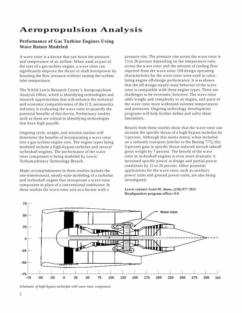
Performance of Gas Turbine Engines UsingWave Rotors Modeled
A wave rotor is a device that can boost the pressureand temperature of an airflow. When used as part ofthe core of a gas turbine engine, a wave rotor cansignificantly improve the thrust or shaft horsepower byboosting the flow pressure without raising the turbineinlet temperature.
The NASA Lewis Research Center’s AeropropulsionAnalysis Office, which is identifying technologies andresearch opportunities that will enhance the technicaland economic competitiveness of the U.S. aeronauticsindustry, is evaluating the wave rotor to quantify thepotential benefits of this device. Preliminary studiessuch as these are critical to identifying technologiesthat have high payoffs.
Ongoing cycle, weight, and mission studies willdetermine the benefits of incorporating a wave rotorinto a gas turbine engine core. The engine types beingmodeled include a high-bypass turbofan and severalturboshaft engines. The performance of the waverotor component is being modeled by Lewis’Turbomachinery Technology Branch.
Major accomplishments in these studies include theone-dimensional, steady-state modeling of a turbofanand turboshaft engine that incorporate a wave rotorcomponent in place of a conventional combustor. Inthese studies the wave rotor acts as a burner with a
pressure rise. The pressure rise across the wave rotor is13 to 20 percent depending on the temperature ratioacross the wave rotor and the amount of cooling flowrequired from the wave rotor. Off-design operatingcharacteristics for the wave rotor were used in calcu-lating engine off-design performance. It was shownthat the off-design steady-state behavior of the waverotor is compatible with these engine types. There arechallenges to be overcome, however. The wave rotoradds weight and complexity to an engine, and parts ofthe wave rotor must withstand extreme temperaturesand pressures. Ongoing technology developmentprograms will help further define and solve theselimitations.
Results from these studies show that the wave rotor canincrease the specific thrust of a high-bypass turbofan by3 percent. Although this seems minor, when includedon a subsonic transport (similar to the Boeing 777), this3-percent gain in specific thrust reduced aircraft takeoffgross weight by 7 percent. The benefit of the waverotor in turboshaft engines is even more dramatic: itincreased specific power at design and partial powerconditions by 15 to 20 percent. Other potentialapplications for the wave rotor, such as auxiliarypower units and ground power units, are also beinginvestigated.
Lewis contact: Scott M. Jones, (216) 977-7015Headquarters program office: OA
–75 0–75
25
50
–25–50
–50
0
–25
25
75
250 275 300 32550 75 100 125 150 175 200 225
Wave rotor
Schematic of high-bypass turborfan with wave rotor component.
325
3
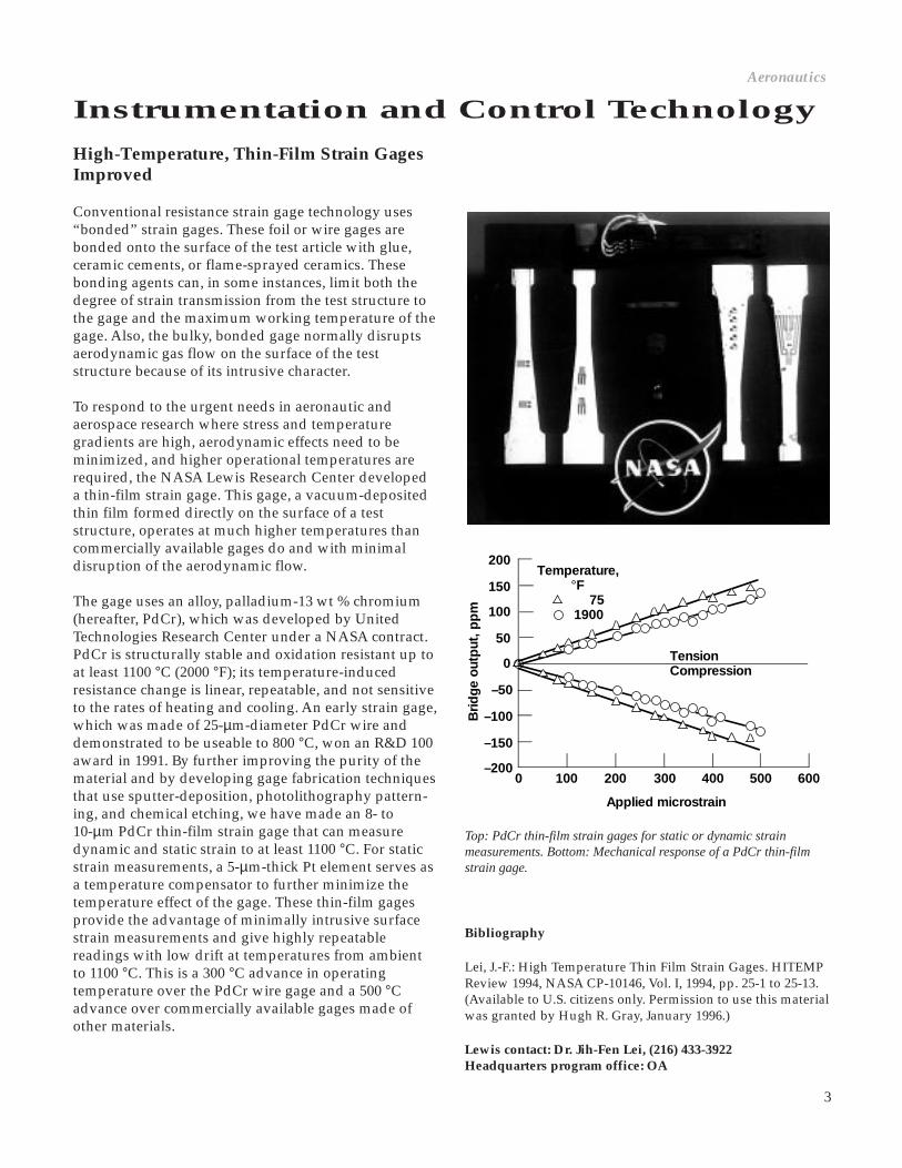
High-Temperature, Thin-Film Strain GagesImproved
Conventional resistance strain gage technology uses“bonded” strain gages. These foil or wire gages arebonded onto the surface of the test article with glue,ceramic cements, or flame-sprayed ceramics. Thesebonding agents can, in some instances, limit both thedegree of strain transmission from the test structure tothe gage and the maximum working temperature of thegage. Also, the bulky, bonded gage normally disruptsaerodynamic gas flow on the surface of the teststructure because of its intrusive character.
To respond to the urgent needs in aeronautic andaerospace research where stress and temperaturegradients are high, aerodynamic effects need to beminimized, and higher operational temperatures arerequired, the NASA Lewis Research Center developeda thin-film strain gage. This gage, a vacuum-depositedthin film formed directly on the surface of a teststructure, operates at much higher temperatures thancommercially available gages do and with minimaldisruption of the aerodynamic flow.
The gage uses an alloy, palladium-13 wt % chromium(hereafter, PdCr), which was developed by UnitedTechnologies Research Center under a NASA contract.PdCr is structurally stable and oxidation resistant up toat least 1100 °C (2000 °F); its temperature-inducedresistance change is linear, repeatable, and not sensitiveto the rates of heating and cooling. An early strain gage,which was made of 25-µm-diameter PdCr wire anddemonstrated to be useable to 800 °C, won an R&D 100award in 1991. By further improving the purity of thematerial and by developing gage fabrication techniquesthat use sputter-deposition, photolithography pattern-ing, and chemical etching, we have made an 8- to10-µm PdCr thin-film strain gage that can measuredynamic and static strain to at least 1100 °C. For staticstrain measurements, a 5-µm-thick Pt element serves asa temperature compensator to further minimize thetemperature effect of the gage. These thin-film gagesprovide the advantage of minimally intrusive surfacestrain measurements and give highly repeatablereadings with low drift at temperatures from ambientto 1100 °C. This is a 300 °C advance in operatingtemperature over the PdCr wire gage and a 500 °Cadvance over commercially available gages made ofother materials.
Instrumentation and Control TechnologyAeronautics
–200
–150
–50
0
50
100
150
200
–100
Applied microstrain
0 100 200 300 400 500 600
Bri
dg
e o
utp
ut, p
pm
TensionCompression
Temperature, °F 75 1900
Top: PdCr thin-film strain gages for static or dynamic strainmeasurements. Bottom: Mechanical response of a PdCr thin-filmstrain gage.
Bibliography
Lei, J.-F.: High Temperature Thin Film Strain Gages. HITEMPReview 1994, NASA CP-10146, Vol. I, 1994, pp. 25-1 to 25-13.(Available to U.S. citizens only. Permission to use this materialwas granted by Hugh R. Gray, January 1996.)
Lewis contact: Dr. Jih-Fen Lei, (216) 433-3922Headquarters program office: OA
4
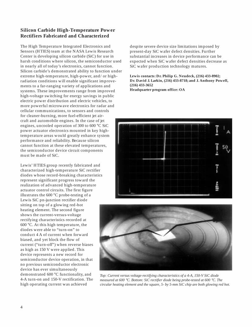
despite severe device size limitations imposed bypresent-day SiC wafer defect densities. Furthersubstantial increases in device performance can beexpected when SiC wafer defect densities decrease asSiC wafer production technology matures.
Lewis contacts: Dr. Philip G. Neudeck, (216) 433-8902;Dr. David J. Larkin, (216) 433-8718; and J. Anthony Powell,(216) 433-3652Headquarter program office: OA
Silicon Carbide High-Temperature PowerRectifiers Fabricated and Characterized
The High Temperature Integrated Electronics andSensors (HTIES) team at the NASA Lewis ResearchCenter is developing silicon carbide (SiC) for use inharsh conditions where silicon, the semiconductor usedin nearly all of today’s electronics, cannot function.Silicon carbide’s demonstrated ability to function underextreme high-temperature, high-power, and/or high-radiation conditions will enable significant improve-ments to a far-ranging variety of applications andsystems. These improvements range from improvedhigh-voltage switching for energy savings in publicelectric power distribution and electric vehicles, tomore powerful microwave electronics for radar andcellular communications, to sensors and controlsfor cleaner-burning, more fuel-efficient jet air-craft and automobile engines. In the case of jetengines, uncooled operation of 300 to 600 °C SiCpower actuator electronics mounted in key high-temperature areas would greatly enhance systemperformance and reliability. Because siliconcannot function at these elevated temperatures,the semiconductor device circuit componentsmust be made of SiC.
Lewis’ HTIES group recently fabricated andcharacterized high-temperature SiC rectifierdiodes whose record-breaking characteristicsrepresent significant progress toward therealization of advanced high-temperatureactuator control circuits. The first figureillustrates the 600 °C probe-testing of aLewis SiC pn-junction rectifier diodesitting on top of a glowing red-hotheating element. The second figureshows the current-versus-voltagerectifying characteristics recorded at600 °C. At this high temperature, thediodes were able to “turn-on” toconduct 4 A of current when forwardbiased, and yet block the flow ofcurrent (“turn-off”) when reverse biasesas high as 150 V were applied. Thisdevice represents a new record forsemiconductor device operation, in thatno previous semiconductor electronicdevice has ever simultaneouslydemonstrated 600 °C functionality, and4-A turn-on and 150-V rectification. Thehigh operating current was achieved
Top: Current versus voltage-rectifying characteristics of a 4-A, 150-V SiC diodemeasured at 600 °C. Bottom: SiC rectifier diode being probe-tested at 600 °C. Thecircular heating element and the square, 5- by 5-mm SiC chip are both glowing red hot.
5
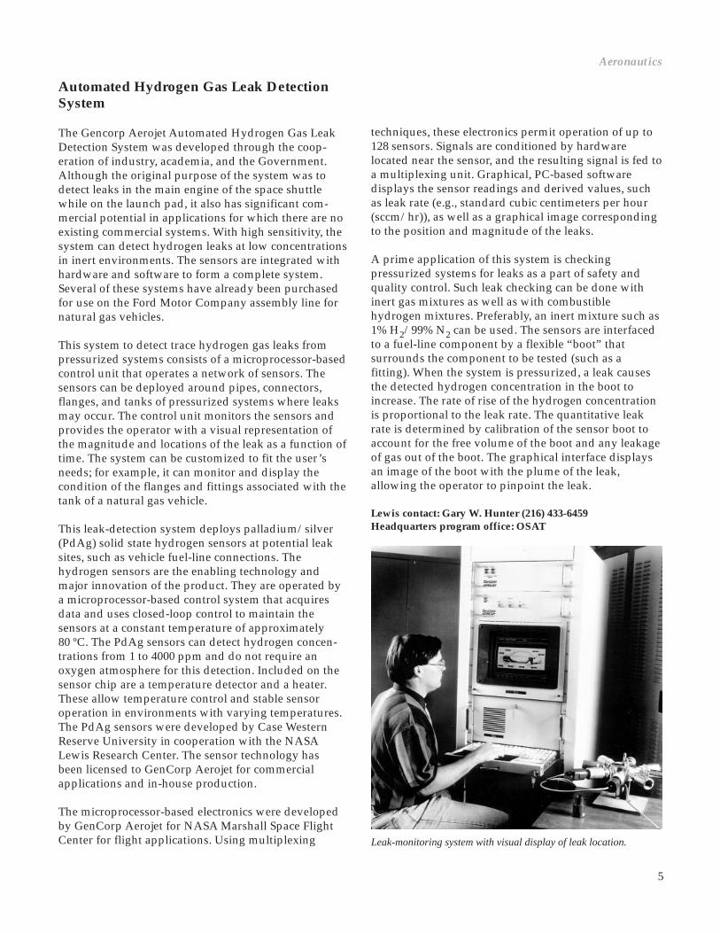
Automated Hydrogen Gas Leak DetectionSystem
The Gencorp Aerojet Automated Hydrogen Gas LeakDetection System was developed through the coop-eration of industry, academia, and the Government.Although the original purpose of the system was todetect leaks in the main engine of the space shuttlewhile on the launch pad, it also has significant com-mercial potential in applications for which there are noexisting commercial systems. With high sensitivity, thesystem can detect hydrogen leaks at low concentrationsin inert environments. The sensors are integrated withhardware and software to form a complete system.Several of these systems have already been purchasedfor use on the Ford Motor Company assembly line fornatural gas vehicles.
This system to detect trace hydrogen gas leaks frompressurized systems consists of a microprocessor-basedcontrol unit that operates a network of sensors. Thesensors can be deployed around pipes, connectors,flanges, and tanks of pressurized systems where leaksmay occur. The control unit monitors the sensors andprovides the operator with a visual representation ofthe magnitude and locations of the leak as a function oftime. The system can be customized to fit the user’sneeds; for example, it can monitor and display thecondition of the flanges and fittings associated with thetank of a natural gas vehicle.
This leak-detection system deploys palladium/silver(PdAg) solid state hydrogen sensors at potential leaksites, such as vehicle fuel-line connections. Thehydrogen sensors are the enabling technology andmajor innovation of the product. They are operated bya microprocessor-based control system that acquiresdata and uses closed-loop control to maintain thesensors at a constant temperature of approximately80 ºC. The PdAg sensors can detect hydrogen concen-trations from 1 to 4000 ppm and do not require anoxygen atmosphere for this detection. Included on thesensor chip are a temperature detector and a heater.These allow temperature control and stable sensoroperation in environments with varying temperatures.The PdAg sensors were developed by Case WesternReserve University in cooperation with the NASALewis Research Center. The sensor technology hasbeen licensed to GenCorp Aerojet for commercialapplications and in-house production.
The microprocessor-based electronics were developedby GenCorp Aerojet for NASA Marshall Space FlightCenter for flight applications. Using multiplexing
techniques, these electronics permit operation of up to128 sensors. Signals are conditioned by hardwarelocated near the sensor, and the resulting signal is fed toa multiplexing unit. Graphical, PC-based softwaredisplays the sensor readings and derived values, suchas leak rate (e.g., standard cubic centimeters per hour(sccm/hr)), as well as a graphical image correspondingto the position and magnitude of the leaks.
A prime application of this system is checkingpressurized systems for leaks as a part of safety andquality control. Such leak checking can be done withinert gas mixtures as well as with combustiblehydrogen mixtures. Preferably, an inert mixture such as1% H2/99% N2 can be used. The sensors are interfacedto a fuel-line component by a flexible “boot” thatsurrounds the component to be tested (such as afitting). When the system is pressurized, a leak causesthe detected hydrogen concentration in the boot toincrease. The rate of rise of the hydrogen concentrationis proportional to the leak rate. The quantitative leakrate is determined by calibration of the sensor boot toaccount for the free volume of the boot and any leakageof gas out of the boot. The graphical interface displaysan image of the boot with the plume of the leak,allowing the operator to pinpoint the leak.
Lewis contact: Gary W. Hunter (216) 433-6459Headquarters program office: OSAT
Leak-monitoring system with visual display of leak location.
Aeronautics

6
Fuzzy Logic Particle Tracking
A new all-electronic Particle Image Velocimetrytechnique that can efficiently map high-speed gasflows has been developed in-house at the NASA LewisResearch Center. Particle Image Velocimetry is anoptical technique for measuring the instantaneoustwo-component velocity field across a planar region ofa seeded flow field. A pulsed laser light sheet is used toilluminate the seed particles entrained in the flow fieldat two instances in time. One or more charged coupleddevice (CCD) cameras can be used to record theinstantaneous positions of particles. Using the timebetween light sheet pulses and determining either theindividual particle displacements or the averagedisplacement of particles over a small subregion of therecorded image enables the calculation of the fluidvelocity. Fuzzy logic minimizes the required operatorintervention in identifying particles and computingvelocity.
Using two cameras that have the same view of theillumination plane yields two single-exposure imageframes. Two competing techniques that yieldunambiguous velocity vector direction informationhave been widely used for reducing the single-exposure, multiple-image frame data: (1) cross-correlation and (2) particle tracking. Correlationtechniques yield averaged velocity estimates oversubregions of the flow, whereas particle trackingtechniques give individual particle velocity estimates.
For the correlation technique, the correlation peakcorresponding to the average displacement of particlesacross the subregion must be identified. Noiseon the images and particle dropout result inmisidentification of the true correlation peak.The subsequent velocity vector maps containspurious vectors where the displacementpeaks have been improperly identified.Typically these spurious vectors are replacedby a weighted average of the neighboringvectors, thereby decreasing the independenceof the measurements.
In this work, fuzzy logic techniques are usedto determine the true correlation displacementpeak even when it is not the maximum peak,hence maximizing the information recoveryfrom the correlation operation, maintainingthe number of independent measurements,and minimizing the number of spuriousvelocity vectors. Correlation peaks arecorrectly identified in both high and low seeddensity cases. The correlation velocity vector
map can then be used as a guide for the particle-tracking operation. Again fuzzy logic techniques areused, this time to identify the correct particle imagepairings between exposures to determine particledisplacements, and thus the velocity (see figure).Combining these two techniques makes use of thehigher spatial resolution available from the particletracking. Particle tracking alone may not be possible inthe high seed density images typically required forachieving good results from the correlation technique.This two-staged velocimetric technique can measureparticle velocities with high spatial resolution over abroad range of seeding densities.
The data shown in the figure are from a two-camerasetup where each camera records a single exposure ofthe particle-seeded flow illuminated by a neodymium:yttrium aluminum garnet (Nd:YAG) laser light sheetpulse. The time between exposures was 500 nsec. Aconvergent nozzle was operated at a plenum pressureof 75 psi, generating an underexpanded jet flow with anexit velocity of Mach 3.25. The effects of the Mach diskcan be seen in the flow, approximately 1.5 nozzlediameters downstream of the nozzle exit plane.Approximately 3000 velocity vectors have beenidentified in the flow. The velocity vector density wasso high that a pseudovelocity-contour plot was createdby color coding the vector magnitudes. The color figureis included in the World Wide Web version of thisreport (http://www.lerc.nasa.gov/WWW/RT1995/2000/2520w. htm).
Particle-tracking velocity vector map of an underexpanded nozzle flow. Pressure,75 psi; nozzle exit velocity, Mach 3.25
7
Bibliography
Wernet, M.P.: Fuzzy Logic Particle-Tracking Velocimetry.Proceedings of the SPIE Conference on Optical Diagnostics inFluid and Thermal Flow, SPIE, Bellingham, WA, 1993, pp.701-708.
Wernet, M.P.: Fuzzy Inference Enhanced InformationRecovery From Digital PIV Using Cross-CorrelationCombined With Particle Tracking. Optical Techniques inFluid, Thermal, and Combustion. S.S. Cha and J.D. Trolinger,eds., SPIE, vol. 2546, 1995, pp. 54-64.
Find out more about Particle Image Velocimetry on theWorld Wide Web:http://www.lerc.nasa.gov/WWW/Optlnstr/piv.html
Lewis contact: Dr. Mark P. Wernet, (216) 433-3752Headquarters program office: OA
Fiber Optic Repair and Maintainability(FORM) Program Progresses
Advanced aircraft will employ fiber-optic intercon-nection components to transmit information fromairframe and propulsion sensors to the flight controlcomputers. Although these optical interconnects havebeen rigorously tested under laboratory conditions todetermine their operating and environmental limits,there is concern as to their repairability andmaintainability when placed in actual service.
The Fiber Optic Repair and Maintainability (FORM)flight test program will provide data to enabledesigners to improve these fiber-optic interconnectionsystems for the next generation of aircraft. FORM isidentifying critical problems in installing, maintaining,testing, and repairing fiber-optic interconnectionsystems in an operational avionics environment. Thisprogram is a cooperative Government/industry effortto evaluate optical component acceptability andinstallation techniques for aircraft.
FORM, which began in 1994, has three phases spanninga 3-year period where approximately 250 flight testhours will be accumulated on experimental fiber-opticcomponents. In Phase I, a total of 60 flight hours wereaccumulated on fiber-optic harnesses and connectorsinstalled onboard the OV-10 aircraft at the NASA LewisResearch Center. This phase was funded by Lewis andNavy Crane, where several participants from theaerospace industry (Sikorsky Aircraft, Amphenol, andDeutsch) supplied the test hardware.
An additional 90 flight hours were accumulated inPhase II, which was funded by the Fly-by-Light/Power-by-Wire program at Lewis. As part of this effort,additional fiber-optic harnesses, provided by SikorskyAircraft and Lockheed Corporation, and optical splices,provided by Aurora Optics, were installed on theaircraft. To date, FORM has flown over 150 hours.
To route the fiber-optic harnesses through the aircraft,we mounted 3/4-in. convoluted conduit through theOV-10 cargo bay, fuselage, wing, boom, and horizontalstabilizer. We compared split and nonsplit conduitinstallation by running separate segments side-by-sidealong the cargo bay and fuselage areas. Another run ofnonsplit conduit extends through the booms to thehorizontal stabilizer and back to the cargo bay. In allinstallations, the conduit was partially filled withelectrical wire to reproduce actual aircraft conditions.
Once the conduit was completely installed and secured,two methods of fiber-optic harness installation weretested. The first method pulls the harnesses through theconduit with a jet line/pull wire that extends the entirelength inside the conduit. One end is attached to thefiber-optic harness and then pulled from the other. Thesecond method slips the optical cables into the splitconduit. Although split conduit provides easy access tothe harnesses, it requires more time to feed fibersthrough than the nonsplit conduit does. The nonsplitconduit provides more protection to the fibers, as wellas ease of installation and removal.
The harnesses were flown unmated for portions of thetests to expose the fiber-optic connectors to contami-nants present in normal aircraft environment. Trans-missive loss measurements were taken before andafter cleaning the connectors during this procedure.
Phase III of FORM will test optical data bus trans-mission and the electro-optical transmission andreception units. It will demonstrate actual data bustransmission through a 1773 optical data bus segmenton the OV-10. The current 1553 data bus on the aircraftwill be modified to include the 1773 segment in its datapath. All the installation and test information collectedin this program will be actively transferred to theprivate vendors for implementation in their ongoingprograms, such as Sikorsky’s Comanche program,Lockheed’s Red Eye, and the F-22 programs.
The NASA OV-10 aircraft used for this test is a twin-engine, two-crew-member, tandem seating turbopropaircraft. It has a top airspeed of 350 kn, a maximum
Aeronautics

8
off-design performance in an engine environment (i.e.,with surrounding turbomachinery). The results indi-cate favorable performance throughout the normaloperating regime.
A multipassage wave rotor simulation is being used toinvestigate transient wave rotor behavior. Preliminaryresults indicate that the wave rotor is stable and wellbehaved even when subjected to severe transient input.Furthermore, the wave rotor response time is very shortwhen compared with conventional turbomachinery.
Lewis is also investigating the concept of removing theexternal combustor and allowing the combustionprocess to occur in the rotor passages (i.e., at con-stant volume). To study this, we modified the one-dimensional simulation to include simple combustionkinetics. Results indicate that the concept is feasible.
Lewis contact: Daniel E. Paxson, (216) 433-8334Headquarters program office: OA
Transient Wave Rotor PerformanceInvestigated
The NASA Lewis Research Center is investigating thewave rotor for use as a core gas generator in future gasturbine engines. The device, which uses gas-dynamicwaves to transfer energy directly to and from theworking fluid through which the waves travel, consistsof a series of constant-area passages that rotate about anaxis. Through rotation, the ends of the passages areperiodically exposed to various circumferentiallyarranged ports that initiate the traveling waves withinthe passages. Because each passage of the wave rotor isperiodically exposed to both hot and cold flow, themean temperature of the rotor material can be expectedto remain considerably below the peak cycle tempera-ture. Estimates made using numerical simulationsindicate that, for a small engine (5 lbm/sec), themean passage wall temperature is approximately360 ºC below the combustor discharge temperature.
A one-dimensional simulation developed at Lewis wasused to generate steady-state performance maps for anoptimally designed wave rotor. These maps were usedin cycle deck studies to assess steady on-design and
4002000Time, msec
0.55
0.50
0.450.40
Exh
aust
flow
rat
e
0.8
0.6
0.40.2F
low
rat
e to
com
bus
tor
0.8
0.6
0.40.2
Flo
w r
ate
fro
mco
mb
usto
r
0.55
0.50
0.450.40In
let
flow
rate
Top: Schematic of transient wave rotor simulation. Bottom: Waverotor response to a 50-percent step change in fuel flow rate;nondimensional port mass flow rate.
NASA OV-10 research aircraft.
altitude of 30,000 ft, and acceleration limits from -1.0 to4.5g.
The OV-10 flight test profiles for this program follow:
• Profile I: Low-altitude navigation (below 5000 ft) at maximum continuous power with numerous accelerated turns and with 3.0 to 4.5g maneuvers in turbulent atmospheric conditions• Profile II: High-altitude navigation (above 21,000 ft)• Profile III: Multiple takeoffs, approaches, and landings
Lewis contact: Jorge L. Sotomayor, 433-8303Headquarters program office: OA

9
Future aircraft turbine engines, both commercial andmilitary, must be able to successfully accommodateexpected increased levels of steady-state and dynamicengine-face distortion. Advanced tactical aircraft arelikely to use thrust vectoring to enhance their maneu-verability. As a result, the engines will see more extremeaircraft angles-of-attack and sideslip levels than arecurrently encountered with present-day aircraft. Also,the mixed-compression inlets needed for the HighSpeed Civil Transport will likely encounter disturb-ances similar to those seen by tactical aircraft, inaddition to planar pulse, inlet buzz, and high distortionlevels at low flight speed and off-design operation.
The current approach of incorporating a sufficientcomponent design stall margin to tolerate theseincreased levels of distortion would significantlyreduce performance. The objective of the High StabilityEngine Control (HISTEC) program is to design,develop, and flight demonstrate an advanced, high-stability, integrated engine-control system that usesmeasurement-based, real-time estimates of distortion toenhance engine stability. The resulting distortion-tolerant control reduces the required design stallmargin, with a corresponding increase in performanceand decrease in fuel burn. The HISTEC concept hasbeen designed and developed, and the softwareimplementing the concept has successfully accommo-dated time-varying distortion. The NASA LewisResearch Center is currently overseeing the develop-ment and validation of the hardware and softwarenecessary to flight test the HISTEC concept. HISTEC isa contracted effort with Pratt & Whitney of West PalmBeach, Florida.
The HISTEC approach includes two major systems:A Distortion Estimation System (DES) and StabilityManagement Control (SMC) (see figure). DES is anaircraft-mounted, high-speed processor that estimatesthe amount and type of distortion present and its effecton the engine. It uses high-response pressure measure-ments at the engine face to calculate indicators of thetype and extent of distortion in real time. From theseindicators, DES determines the effects of distortion onthe propulsion systems and the corresponding enginematch point necessary to accommodate it. DES outputconsists of fan and compressor pressure ratio trimcommands that are passed to the SMC. In addition,DES uses maneuver information, consisting of angle-of-attack and sideslip from the flight control, to anticipatehigh inlet distortion conditions. The SMC, which iscontained in the engine-mounted, Improved Digital
Electronic Engine Control (IDEEC), includes advancedcontrol laws to directly control the fan and compressortransient operating line (pressure ratio). Theseadvanced control laws, with a multivariable design,have the potential for higher bandwidth and theresulting more precise control of engine match. Theability to measure and assess the distortion effects inreal time coupled with a high-response controllerimproves engine stability at high levels of distortion.
The software algorithms implementing DES havebeen designed, developed, and demonstrated, andintegration testing of the DES and SMC software hasbeen completed. The results show that the HISTECsystem will be able to sense inlet distortion, determinethe effect on engine stability, and accommodatedistortion by maintaining an adequate margin forengine surge. The Pratt & Whitney ComprehensiveEngine Diagnostic Unit was chosen as the DESprocessor. An instrumented inlet case for sensingdistortion was designed and fabricated. HISTEC isscheduled for flight test on the ACTIVE F-15 aircraft atthe NASA Dryden Flight Research Center in Edwards,California, in late 1996.
Bibliography
Ouzts, P.J.; Lorenzo, C.F.; and Merrill, W.C.: Screening Studiesof Advanced Control Concepts for Airbreathing Engines.NASA TM-106042, 1993.
Southwick, R.D., et al.: High Stability Engine Control(HISTEC) Phase I: Algorithm Development, Volume I: FinalReport and Appendix A. NASA CR-198399, 1995. (Permissionto use this material was granted by Sanjay Garg, February
Lewis contact: John C. DeLaat, (216) 433-3744Headquarters program office: OA
Aeronautics
Concept Designed and Developed for Distortion-Tolerant, High-Stability Engine Control
ActuatorCommands
From FLTControl
Predicted α, β
DistortionSensors
DistortionEstimation System
• Distortion Estimates• Engine Sensitivites
IDEECTrim
Commands
IDEECStability Management
Control LawsMultivariable Design
Distortion Tolerant Control. (Copyright Pratt & Whitney; used withpermission.)
1996.)
10
Internal Fluid Mechanics
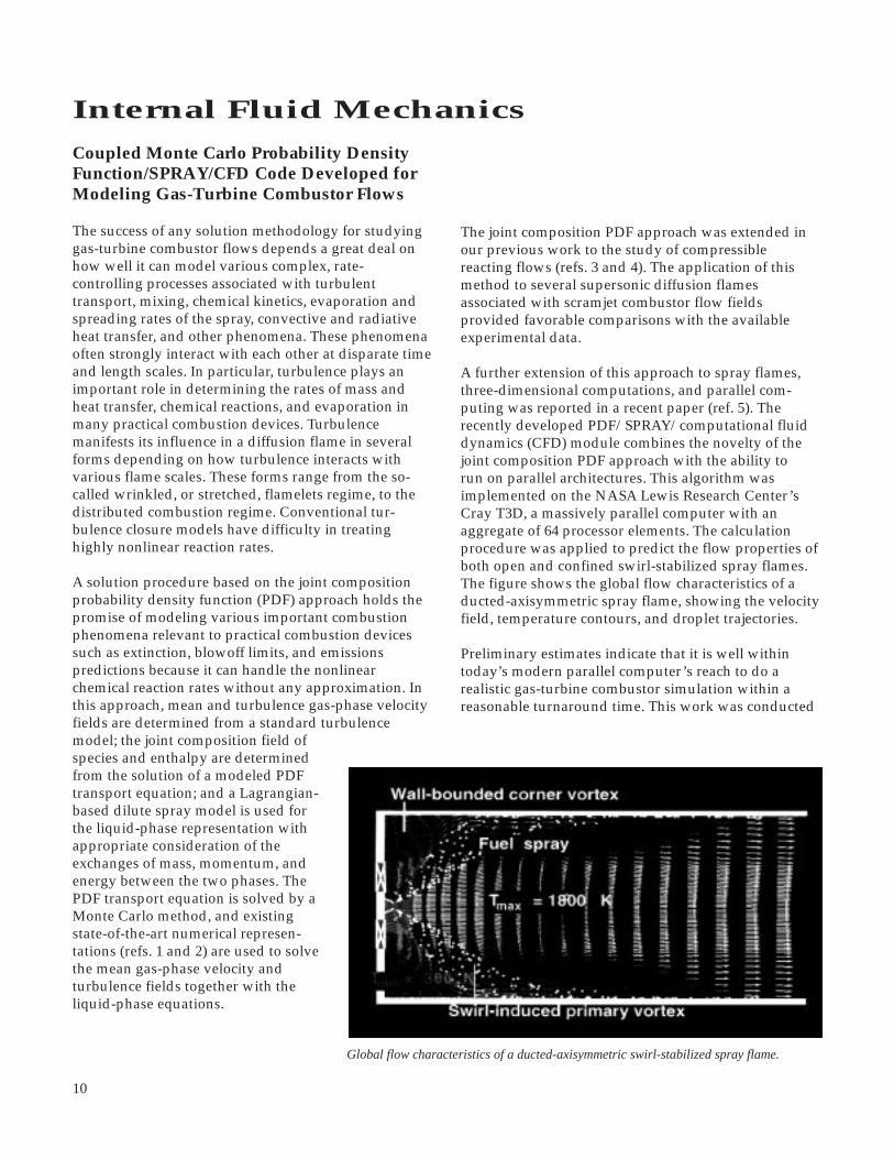
Coupled Monte Carlo Probability DensityFunction/SPRAY/CFD Code Developed forModeling Gas-Turbine Combustor Flows
The success of any solution methodology for studyinggas-turbine combustor flows depends a great deal onhow well it can model various complex, rate-controlling processes associated with turbulenttransport, mixing, chemical kinetics, evaporation andspreading rates of the spray, convective and radiativeheat transfer, and other phenomena. These phenomenaoften strongly interact with each other at disparate timeand length scales. In particular, turbulence plays animportant role in determining the rates of mass andheat transfer, chemical reactions, and evaporation inmany practical combustion devices. Turbulencemanifests its influence in a diffusion flame in severalforms depending on how turbulence interacts withvarious flame scales. These forms range from the so-called wrinkled, or stretched, flamelets regime, to thedistributed combustion regime. Conventional tur-bulence closure models have difficulty in treatinghighly nonlinear reaction rates.
A solution procedure based on the joint compositionprobability density function (PDF) approach holds thepromise of modeling various important combustionphenomena relevant to practical combustion devicessuch as extinction, blowoff limits, and emissionspredictions because it can handle the nonlinearchemical reaction rates without any approximation. Inthis approach, mean and turbulence gas-phase velocityfields are determined from a standard turbulencemodel; the joint composition field ofspecies and enthalpy are determinedfrom the solution of a modeled PDFtransport equation; and a Lagrangian-based dilute spray model is used forthe liquid-phase representation withappropriate consideration of theexchanges of mass, momentum, andenergy between the two phases. ThePDF transport equation is solved by aMonte Carlo method, and existingstate-of-the-art numerical represen-tations (refs. 1 and 2) are used to solvethe mean gas-phase velocity andturbulence fields together with theliquid-phase equations.
Global flow characteristics of a ducted-axisymmetric swirl-stabilized spray flame.
The joint composition PDF approach was extended inour previous work to the study of compressiblereacting flows (refs. 3 and 4). The application of thismethod to several supersonic diffusion flamesassociated with scramjet combustor flow fieldsprovided favorable comparisons with the availableexperimental data.
A further extension of this approach to spray flames,three-dimensional computations, and parallel com-puting was reported in a recent paper (ref. 5). Therecently developed PDF/SPRAY/computational fluiddynamics (CFD) module combines the novelty of thejoint composition PDF approach with the ability torun on parallel architectures. This algorithm wasimplemented on the NASA Lewis Research Center’sCray T3D, a massively parallel computer with anaggregate of 64 processor elements. The calculationprocedure was applied to predict the flow properties ofboth open and confined swirl-stabilized spray flames.The figure shows the global flow characteristics of aducted-axisymmetric spray flame, showing the velocityfield, temperature contours, and droplet trajectories.
Preliminary estimates indicate that it is well withintoday’s modern parallel computer’s reach to do arealistic gas-turbine combustor simulation within areasonable turnaround time. This work was conducted

11
Aeronautics
in collaboration with Dr. M.S. Raju of NYMA, Inc.,whose journal article with A.T. Hsu and Y.-L.P. Tsai(ref. 3) received NYMA, Inc.’s, best technical paper ofthe year award for 1994.
References
1. Raju M.S.: Heat Transfer and Performance Characteristics of a Dual-Ignition Wankel Engine. SAE Paper 920303, SAE Tech. Lit. Abstr., 1992.
2. Shyy, W.; Correa, S.M.; and Braaten, M.E.: Computation of Flow in a Gas Turbine Combustor. Combust. Sci. Tech., vol. 58, 1988, pp. 97-117.
3. Hsu, A.T.; Tsai Y.-L.P.; and Raju M.S.: Probability Density Function Approach for Compressible Turbulent Reacting Flows. AIAA Journal, vol. 32, no. 7, pp. 1407-1415, 1994.
4. Hsu A.T.; Raju M.S.; and Norris A.T.: Application of a pdf Method to Compressible Turbulent Reacting Flows. AIAA Paper 94-0781, 1994.
5. Raju, M.S.: Coupled Monte-Carlo-PDF/SPRAY/CFD Computations of Swirl-Stabilized Flames. AIAA Paper 95- 2442, 1995.
Lewis contact: Dr. D.R. Reddy, (216) 433-8133Headquarters program office: OA
three-dimensional grid generator to help automate theoptimization procedure.
The inlet lip shape at the crown and the keel wasdescribed as a super-ellipse, and the super-ellipseexponents and radii ratios were considered as designvariables. Three operating conditions: cruise, takeoff,and rolling takeoff, were considered in this study.Three-dimensional Euler computations were carriedout to obtain the flow field. At the initial design, thepeak Mach numbers for maximum cruise, takeoff, androlling takeoff conditions were 0.88, 1.772, and 1.61,respectively. The acceptable upper limits on the takeoffand rolling takeoff Mach numbers were 1.55 and 1.45.Since the initial design provided by Boeing was foundto be optimum with respect to the maximum cruisecondition, the sum of the peak Mach numbers at takeoffand rolling takeoff were minimized in the current studywhile the maximum cruise Mach number wasconstrained to be close to that at the existing design.
CFD-Based Design Optimization ToolDeveloped for Subsonic Inlet
The traditional approach to the design of engine inletsfor commercial transport aircraft is a tedious processthat ends with a less-than-optimum design. With theadvent of high-speed computers and the availabilityof more accurate and reliable computational fluiddynamics (CFD) solvers, numerical optimization proc-esses can effectively be used to design an aerodynamicinlet lip that enhances engine performance. The design-ers’ experience at Boeing Corporation showed that fora peak Mach number on the inlet surface beyond someupper limit, the performance of the engine degradesexcessively. Thus, our objective was to optimizeefficiency (minimize the peak Mach number) at maxi-mum cruise without compromising performance atother operating conditions.
Using the CFD code NPARC, the NASA LewisResearch Center, in collaboration with Boeing,developed an integrated procedure at Lewis to find theoptimum shape of a subsonic inlet lip and a numericaloptimization code, ADS. We used a GRAPE-based
Top: Inlet and sample three-dimensional grid in twoplanes. Alternate grid lines shown along the radialdirection. Bottom: Comparison of peak Mach numbersat initial and optimum designs.

12
With this objective, the optimum design satisfied theupper limits at takeoff and rolling takeoff whileretaining the desirable cruise performance. Furtherstudies are being conducted to include static and cross-wind operating conditions in the design optimizationprocedure. This work was carried out in collaborationwith Dr. E.S. Reddy of NYMA, Inc.
Bibliography
Mason, J.G., et al.: Inlet Design Using a Blend of Experimentaland Computational Techniques. Proceedings of the 18th ICASCongress, AIAA, Washington, DC, 1992, pp. 445-454.
Reddy, E.S.; and Reddy, D.R.: Aerodynamic ShapeOptimization of a Subsonic Inlet Using 3-D EulerComputation. AIAA Paper 95-2757, 1995.
Sorenson, R.L.: A Computer Program to Generate Two-Dimensional Grids About Airfoils and Other Shapes by theUse of Poisson’s Equation. NASA TM-81198, 1980.
Vanderplaats, G.N.: ADS: A Fortran Program for AutomatedDesign Synthesis: Version 1.10. Final Report. NASA CR-177985, 1985.
Lewis contact: Dr. D.R. Reddy, (216) 433-8133Headquarters program office: OA
User Interface Developed for Controls/CFDInterdisciplinary Research
The NASA Lewis Research Center, in conjunction withthe University of Akron, is developing analyticalmethods and software tools to create a cross-discipline“bridge” between controls and computational fluiddynamics (CFD) technologies (ref. 1). Traditionally, thecontrols analyst has used simulations based on largelumping techniques to generate low-order linearmodels convenient for designing propulsion systemcontrols. For complex, high-speed vehicles such as theHigh Speed Civil Transport (HSCT), simulations basedon CFD methods are required to capture the relevantflow physics. The use of CFD should also help reducethe development time and costs associated withexperimentally tuning the control system. The initialapplication for this research is the High Speed CivilTransport inlet control problem.
A major aspect of this research is the development of acontrols/CFD interface for non-CFD experts, tofacilitate the interactive operation of CFD simulationsand the extraction of reduced-order, time-accuratemodels from CFD results. A distributed computing
approach for implementing the interface is beingexplored. Software being developed as part of theIntegrated CFD and Experiments (ICE) project providesthe basis for the operating environment, including run-time displays and information (data base) management.Message-passing software is used to communicatebetween the ICE system and the CFD simulation, whichcan reside on distributed, parallel computing systems.Initially, the one-dimensional Large-Perturbation Inlet(LAPIN) code is being used to simulate a High SpeedCivil Transport type inlet. LAPIN can model realsupersonic inlet features, including bleeds, bypasses,and variable geometry, such as translating or variable-ramp-angle centerbodies. Work is in progress to useparallel versions of the multidimensional NPARC code.
The figure shows a snapshot of one display configur-ation of the Controls/CFD user interface duringinteractive operation of LAPIN. The CFD codeexecution mode is controlled by the RUN and STOPbuttons at the lower left of the screen. The RECORDbutton permits the user to start or stop recording flowfield information at any time. The SAVE button enablesusers to save the recorded information as a permanentfile in the ICE data base. With LAPIN, execution anddisplay updates both occur in near-real time. The upperleft quadrant shows the code execution status andslider bars for interactively controlling the inlet and exitboundary conditions (only the slider bar for the free-stream temperature set point is visible in this screen).
In this case, LAPIN is simulating the response of theinlet without control, while operating at a free-streamMach number of 2.35 and an exit Mach numberoperating-point value of 0.4223. The inlet is beingperturbed by a 40-Hz sinusoid in the exit Mach numberwith a 3.0-percent zero-to-peak amplitude. The lowerleft quadrant shows some of the variables that can bechanged interactively to affect the LAPIN execution(e.g., variables specifying the inlet perturbation). Theupper right quadrant shows time histories of two inletvariables—Mach number at the exit (lower curve) andMach number at a location downstream of, but near,the normal shock. Phase shift between the two signalscan be measured by the two vertical lines, which aremanually positioned by clicking on the horizontal axis.(Horizontal lines for determining amplitude responsecan be positioned by clicking on the vertical axis.) Thelower right plot shows the “instantaneous” axial static-pressure distribution in the inlet. The nearly discontin-uous jump in pressure indicates the location of thenormal shock.

13
Aeronautics
Controls/CFD user interface.
Wavelet techniques are very suitable for analyzing thecomplex turbulent and transitional flows pervasive injet engines. These flows are characterized by intermit-tency and a multitude of scales. Wavelet analysis resultsin information about these scales and their locations.The distribution of scales is equivalent to the frequencyspectrum provided by commonly used Fourier analysistechniques; however, no localization information isprovided by Fourier analysis. In addition, wavelettechniques allow conditional sampling analyses of theindividual scales, which is not possible by Fouriermethods.
The NASA Lewis Research Center developed variouswavelet-based algorithms for post-processing the time-trace signals of transitional and turbulent flows (ref. 1).The techniques were demonstrated by analysis of theexperimental hot-wire data from the bypass transitionexperiments conducted at Lewis by Sohn and Reshotko(ref. 2). The figure displays the stress map, a plotexclusively constructed by wavelet processing of twosimultaneous signals of the velocity components. Itshows the contributions of the various scales to theReynolds stress at a point in the flow. The structure ofthis map indicates that dominant scales contribute tothe momentum transport—an important conclusion.Conditional sampling showed that the scales thatcontribute to the transport in the turbulent parts of thesignals do not contribute to the energy transport. Thisinformation will be used in modeling bypass transition,which is prevalent in turbomachinery flow.
The techniques were developed at Lewis, in collabo-ration with Dr. Jacques Lewalle of Syracuse University,under a contract funded by the Lewis Director’sdiscretionary fund. The software developed is availablefor collaborative work with industry and academia.One collaborative project is currently underway withDr. D. Wisler and D. Halstead of GE Aircraft Engines inEvandale, Ohio. Under this project, data from turbineand compressor experiments performed at the GeneralElectric Company (ref. 3) are being analyzed at Lewiswith wavelet techniques as part of Lewis’ Low PressureTurbine Flow Physics Program.
References
1. Lewalle, J.; and Ashpis, D.E.: Demonstration of Wavelet Techniques in the Spectral Analysis of Bypass Transition Data. NASA TP-3555, 1995.
2. Sohn, K-H.; and Reshotko E.: Experimental Study of Boundary Layer Transition With Elevated Freestream Turbulence on a Heated Flat Plate. NASA CR-187068, 1991.
Wavelet Techniques Applied to ModelingTransitional/Turbulent Flows inTurbomachinery
Computer simulation is an essential part of the designand development of jet engines for the aeropropulsionindustry. Engineers concerned with calculating theflow in jet engine components, such as compressorsand turbines, need simple engineering models thataccurately describe the complex flow of air and gasesand that allow them to quickly estimate loads, losses,temperatures, and other design parameters. In thisongoing collaborative project, advanced waveletanalysis techniques are being used to gain insight intothe complex flow phenomena. These insights, whichcannot be achieved by commonly used methods, arebeing used to develop innovative new flow models andto improve existing ones.
Reference
1. Cole, G.L., et al.: Computational Methods for HSCT-InletControls/CFD Interdisciplinary Research. AIAA Paper94-3209, 1994.
For more information about Controls/CFD and ICEresearch, visit our World Wide Web sites:http://www.lerc.nasa.gov/WWW/IFMD/2620/homepage.htmlhttp://controls.lerc.nasa.gov:8080/projects/cntrlcfd/index.htm
Lewis contact: Gary L. Cole, (216) 433-3655Headquarters program office: OA

14
The Low-Speed Compressor features shrouded statorseal cavities with a single labyrinth seal tooth. Measure-ments of the power stream aerodynamics have beenmade for a range of seal tooth clearances. In the initialseries of tests, the seal tooth clearances were changed inall four stages. In a second series of tests, the sealclearance was changed in only the third stage. Resultsfrom both test series indicate that significant changes inthe power stream aerodynamics occur with differentseal leakage rates. For example, the change in totalpressure loss across the third stator is shown in thefigure for a range of seal tooth clearances. The mea-sured results indicate that the power stream aero-dynamics are influenced across the lower 40 percentof the blade span by the leakage flow. The measuredresults will be compared with computational fluiddynamics simulations in which the seal cavity isincluded in the computational domain. The results willalso be used to develop a simple leakage flow modelfor future computational fluid dynamics simulations sothat the actual seal cavity will not have to be includedin the computational domain.
Lewis contact: Dr. Michael D. Hathaway, (216) 433-6250Headquarters program office: OA
Effect of Shrouded Stator Leakage Flows onCore Compressor Studied
Efforts to improve core compressor technology havetraditionally focused on improving the power streamaerodynamics. During core compressor design andnumerical simulation, the effects of leakage flows havebeen modeled with relatively simple approximations.A combined experimental/numerical research pro-gram aimed at studying the effects of the leakage flowunder core compressor shrouded stators was thereforeundertaken to improve our ability to predict the effectsof this leakage flow on power stream aerodynamics.The experimental effort involves detailed measure-ments in both the seal cavity and power stream in the4-ft-diameter, four-stage NASA Low-Speed Compres-sor. The numerical simulation effort involves three-dimensional Navier-Stokes simulations of the Low-Speed Compressor (performed in-house at theNASA Lewis Research Center) and simulations of arepresentative high-speed core exit stage (performedunder contract by Allison Engine Company).
Investigation of leakage effects on the aerodynamic performance ofshrouded compressor stators. Top: Meridional view of NASA’s low-speed axial-flow compressor. Bottom: Pressure loss coefficient asfunction of percent span from hub.
3. Halstead, D.E., et al.: Boundary Layer Development in Axial Compressors and Turbines. Parts 1-4, ASME Papers 95-GT-461, 462, 463, and 464, 1995.
Lewis contact: Dr. David E. Ashpis, (216) 433-8317Headquarters program office: OA
0.004–0.004
U t
ime
scal
es, s
ec
Level of contribution to Reynold'sstress per unit density
10–5
0
10–3
10–5
10–4
10–410–3
V time scales, sec
Wavelet-based stress map. U is the streamwise velocity, and V is thenormal velocity. (Data are from ref. 2, grid G1, at x = 0.9 in. and y =0.030 in.)
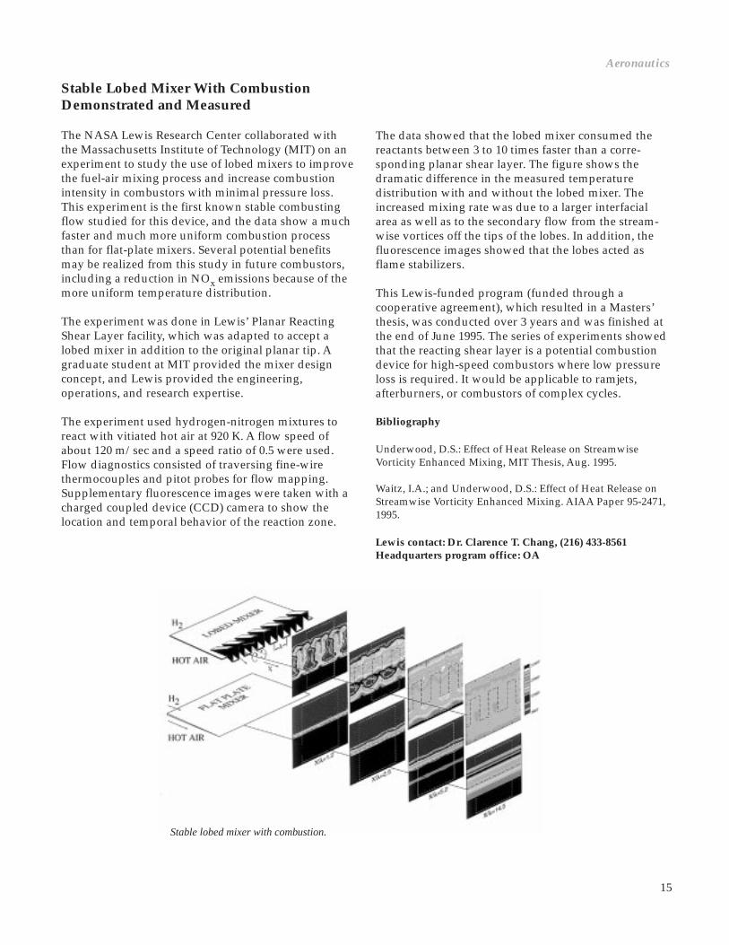
15
The data showed that the lobed mixer consumed thereactants between 3 to 10 times faster than a corre-sponding planar shear layer. The figure shows thedramatic difference in the measured temperaturedistribution with and without the lobed mixer. Theincreased mixing rate was due to a larger interfacialarea as well as to the secondary flow from the stream-wise vortices off the tips of the lobes. In addition, thefluorescence images showed that the lobes acted asflame stabilizers.
This Lewis-funded program (funded through acooperative agreement), which resulted in a Masters’thesis, was conducted over 3 years and was finished atthe end of June 1995. The series of experiments showedthat the reacting shear layer is a potential combustiondevice for high-speed combustors where low pressureloss is required. It would be applicable to ramjets,afterburners, or combustors of complex cycles.
Bibliography
Underwood, D.S.: Effect of Heat Release on StreamwiseVorticity Enhanced Mixing, MIT Thesis, Aug. 1995.
Waitz, I.A.; and Underwood, D.S.: Effect of Heat Release onStreamwise Vorticity Enhanced Mixing. AIAA Paper 95-2471,1995.
Lewis contact: Dr. Clarence T. Chang, (216) 433-8561Headquarters program office: OA
Aeronautics
Stable Lobed Mixer With CombustionDemonstrated and Measured
The NASA Lewis Research Center collaborated withthe Massachusetts Institute of Technology (MIT) on anexperiment to study the use of lobed mixers to improvethe fuel-air mixing process and increase combustionintensity in combustors with minimal pressure loss.This experiment is the first known stable combustingflow studied for this device, and the data show a muchfaster and much more uniform combustion processthan for flat-plate mixers. Several potential benefitsmay be realized from this study in future combustors,including a reduction in NOx emissions because of themore uniform temperature distribution.
The experiment was done in Lewis’ Planar ReactingShear Layer facility, which was adapted to accept alobed mixer in addition to the original planar tip. Agraduate student at MIT provided the mixer designconcept, and Lewis provided the engineering,operations, and research expertise.
The experiment used hydrogen-nitrogen mixtures toreact with vitiated hot air at 920 K. A flow speed ofabout 120 m/sec and a speed ratio of 0.5 were used.Flow diagnostics consisted of traversing fine-wirethermocouples and pitot probes for flow mapping.Supplementary fluorescence images were taken with acharged coupled device (CCD) camera to show thelocation and temporal behavior of the reaction zone.
Stable lobed mixer with combustion.

16
Effect of Tabs on a Rectangular NozzleStudied
In a continuing research program, jets from nozzles ofdifferent geometries are being investigated with the aimof increasing mixing and spreading in those flows.Flow fields from nozzles with elliptic, rectangular, andother more complex cross-sectional shapes are beingstudied in comparison to circular nozzles over a wideMach number range. As noted by previous researchers,noncircular jets usually spread faster than circular jets.
Another technique being investigated to increase jetspreading even further for a given nozzle is the use of“tabs” to generate vortices. A typical tab is a triangular-shaped protrusion placed at the nozzle exit, with thebase of the triangle touching the nozzle wall and theapex leaning downstream at 45° to the stream direction.This geometry was determined by a parametric studyto produce the optimum effect for a given area block-age. The tabs can increase jet spreading significantly.The underlying mechanism traces to a pair of counter-rotating streamwise vortices originating from each tab.These vortex pairs persist in the flow; and with theappropriate number and strength, they can increasespreading.
With jets from noncircular nozzles, the effect of the tabsis relatively more complex. Such flows usually containstreamwise vortices, even without any tabs, becauseof the tortuous flow paths within the nozzle. Whentabs are applied, the resulting vortex pairs interactwith the already existing vortices. Thus, dependingon the location, size, and orientation of the tabs, the
vortex interaction can be either beneficial, increasingspreading, or detrimental, actually reducing spreading.
With a suitable choice of the tabs, a large increase in jetspreading can be achieved with noncircular nozzles. Anexample is shown in the figure. Here, the nozzle isrectangular with an aspect ratio of 3:1. The Reynoldsnumber is 450,000, and the Mach number is 0.3. Thedata are obtained by hot-wire anemometry. Each figurein the left column shows an “isosurface” of the meanvelocity, U/UJET = 15 percent, providing a perspectiveview of the jet spreading. It can be seen that the jet crosssection for the no-tab case has become essentially roundby the last measurement station, x/DEQUIVALENT = 8.For the case in the lower figure, two relatively largetabs are used, one each on the narrow edges of thenozzle. The tabs cause an enormous increase in the jetspreading. The increase in the amount of entrainedambient air at x/DEQUIVALENT = 8 is about 100 percent.Note also that the tabs cause “axis switching”; that is,whereas the long dimension of the nozzle is alignedvertically, that of the jet cross section becomeshorizontal shortly downstream of the nozzle.
The two figures on the right show the correspondingdistributions of streamwise vorticity. Looking fromdownstream, the darker and lighter isosurfacesrepresent regions of anticlockwise and clockwiserotation, respectively. In the no-tab case, as mentionedearlier, two pairs of vortices occur because of secondaryflow within the nozzle. It should be evident that thetabs produce very strong vortex pairs with oppositerotation directions. These vortex pairs completelydominate the flow field, and are responsible for theobserved increase in the jet spreading as well as the axisswitching. The effect of the tabs in this configurationhas also been found to be persistent and, in fact, morepronounced at supersonic conditions.
Current effort in the research includes testing withmore practical nozzles relevant to the High SpeedCivil Transport (HSCT) and the Advanced SubsonicTechnology (AST) programs. Efforts are also under wayto address fundamental issues: for example, vorticitydynamics, mixedness, and small-scale mixing, asaffected by the tabs, relevant to combustor flows and jetnoise. In a parallel computational study, the flow fieldwas also simulated successfully by a three-dimensionalNavier-Stokes analysis. Currently, a parametric studyis being carried out in the computational work byvarying the tab size, orientation, and other factors—complementing and guiding the experimental work.
Distributions of mean velocity and streamwise vorticity with andwithout the tabs. Nozzle exit is shown on the left of each figure;flow is from left to right.
Streamwise velocityMean velocity
No tab No tab
Tab Tab

17
Aeronautics
Bibliography
Steffen, C.J.; Reddy, D.R.; and Zaman, K.B.M.Q.: Analysis ofFlowfield From a Rectangular Nozzle With Delta Tabs. AIAAPaper 95-2146, 1995.
Zaman, K.B.M.Q.; Reeder, M.F.; and Samimy, M.: Control ofan Axisymmetric Jet Using Vortex Generators, Phys. Fluids,vol. 6, no. 2, Feb. 1993, pp. 778-793.
Zaman, K.B.M.Q.: Axis Switching and Spreading of anAsymmetric Jet—Role of Vorticity Dynamics. AIAA Paper95-0889, 1995.
Lewis contacts: Dr. Khairul Zaman, (216) 433-5888;Christopher J. Steffen, Jr., (216) 433-8508; andDr. Judith K. Foss, (216) 433-3587Headquarters program office: OA
Propulsion SystemsSpherical Joint Piston and Connecting RodDeveloped
Under an interagency agreement with the Departmentof Energy, the NASA Lewis Research Center managesa Heavy-Duty Diesel Engine Technology (HDET)research program. The overall program objectives areto reduce fuel consumption through increased engineefficiency, reduce engine exhaust emissions, andprovide options for the use of alternative fuels. Theprogram is administered with a balance of researchcontracts, university research grants, and focusedin-house research.
The Cummins Engine Company participates in theHDET program under a cost-sharing research contract.Cummins is researching and developing in-cylindercomponent technologies for heavy-dutydiesel engines. An objective of theCummins research is to developtechnologies for a low-emissions,55-percent thermal efficiency (LE-55)engine. The best current-productionengines in this class achieve about 46-percent thermal efficiency. Federalemissions regulations are driving thistechnology. Regulations for heavy-dutydiesel engines were tightened in 1994,more demanding emissions regulationsare scheduled for 1998, and anotherstep is planned for 2002. The LE-55engine emissions goal is set at half of
the 1998 regulation level and is consistent with plansfor 2002 emissions regulations.
LE-55 engine design requirements to meet the efficiencytarget dictate a need to operate at higher peak cylinderpressures. A key technology being developed andevaluated under the Cummins Engine Company LE-55engine concept is the spherical joint piston and connect-ing rod. Unlike conventional piston and connecting rodarrangements which are joined by a pin forming ahinged joint, the spherical joint piston and connectingrod use a ball-and-socket joint. The ball-and-socketarrangement enables the piston to have an axisym-metric design allowing rotation within the cylinder. Thepotential benefits of piston symmetry and rotation arereduced scuffing, improved piston ring sealing,improved lubrication, mechanical and thermal loadsymmetry, reduced bearing stresses, reduced runningclearances, and reduced oil consumption.
The spherical joint piston is a monolithic, squeeze-cast,fiber-reinforced aluminum piston. The connecting rodhas a ball end that seats on a spherical saddle withinthe piston and is retained by a pair of aluminumbronze holder rings. The holder rings are securedby a threaded ring that mates with the piston.
As part of the ongoing research and developmentactivity, the Cummins Engine Company successfullycompleted a 100-hr test of the spherical joint pistonand connecting rod at LE-55 peak steady-state engineconditions. In addition, a 100-hr transient cycle test thatvaried engine conditions between LE-55 no-load andLE-55 full-load was successfully completed.
Lewis contact: Dr. Mark J. Valco, (216) 433-3717Headquarters program office: OA
Spherical joint piston and connecting rod—exploded assembly.
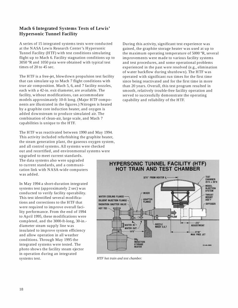
18
During this activity, significant test experience wasgained, the graphite storage heater was used at up tothe maximum operating temperature of 5000 ºR, severalimprovements were made to various facility systemsand test procedures, and some operational problemsexperienced in the past were resolved (e.g., eliminationof water backflow during shutdown). The HTF wasoperated with significant run times for the first timesince being reactivated and for the first time in morethan 20 years. Overall, this test program resulted insmooth, relatively trouble-free facility operation andserved to successfully demonstrate the operatingcapability and reliability of the HTF.
Mach 6 Integrated Systems Tests of Lewis’Hypersonic Tunnel Facility
A series of 15 integrated systems tests were conductedat the NASA Lewis Research Center’s HypersonicTunnel Facility (HTF) with test conditions simulatingflight up to Mach 6. Facility stagnation conditions up to3050 ºR and 1050 psia were obtained with typical testtimes of 20 to 45 sec.
The HTF is a free-jet, blowdown propulsion test facilitythat can simulate up to Mach 7 flight conditions withtrue air composition. Mach 5, 6, and 7 facility nozzles,each with a 42-in. exit diameter, are available. Thefacility, without modifications, can accommodatemodels approximately 10-ft long. (Major HTF compo-nents are illustrated in the figures.) Nitrogen is heatedby a graphite core induction heater, and oxygen isadded downstream to produce simulated air. Thecombination of clean-air, large scale, and Mach 7capabilities is unique to the HTF.
The HTF was reactivated between 1990 and May 1994.This activity included refurbishing the graphite heater,the steam generation plant, the gaseous oxygen system,and all control systems. All systems were checkedout and recertified, and environmental systems wereupgraded to meet current standards.The data systems also were upgradedto current standards, and a communi-cation link with NASA-wide computerswas added.
In May 1994 a short-duration integratedsystems test (approximately 2 sec) wasconducted to verify facility operability.This test identified several modifica-tions and corrections to the HTF thatwere required to improve overall faci-lity performance. From the end of 1994to April 1995, these modifications werecompleted, and the 3000-ft-long, 30-in.-diameter steam supply line wasinsulated to improve system efficiencyand allow operation in all weatherconditions. Through May 1995 theintegrated systems were tested. Thephoto shows the facility steam ejectorin operation during an integratedsystems test. HTF hot train and test chamber.

19
Capabilities Enhanced for Researching theReduction of Emissions in Future Aircraft
Future aircraft jet engines will run at higher pressuresto obtain greater fuel efficiency and performance. Thiswill require new combustor designs to keep thenitrogen oxide and carbon monoxide emissions atenvironmentally acceptable levels.
The actual pressures and temperatures found in gasturbine combustors must be duplicated in a laboratoryto verify the emissions characteristics of gas turbineengines. Recognizing this, the U.S. aircraft gas turbineindustry identified a need for a national facility thatcould duplicate the severe inlet conditions of futurecombustors.
Because of our expertise in combustion emissionsreduction research and in the design and operation ofhigh-pressure test facilities, the NASA Lewis ResearchCenter was seen as the natural location for such afacility. As a national laboratory, Lewis could providethese facilities to all U.S. gas turbine engine manufac-turers while protecting their proprietary interests.
Called the Advanced Subsonic Combustion Rig (seefigure), the facility will provide up to 60-atm pressuresat inlet temperatures up to 1300 ºF and air flow rates upto 38 lb/sec. Furthermore, it will offer state-of-the-artdiagnostic methods for characterizing advancedcombustor concepts.
Aeronautical combustion research at Lewis providedseveral significant accomplishments recently in supportof both the High Speed Research (HSR) and AdvancedSubsonic Technology (AST) programs. For example, inthe High Speed Research Program, NOx reductions ofup to 90 percent were achieved in prototype combustorhardware. Advanced computational analysis, gassampling, and laser diagnostic techniques were criticalto this success.
Working closely with the gas turbine industry, wehave successfully transferred this low-emissions com-bustor technology into engine prototype hardware.This hardware is now being tested at the engine
Aeronautics
Bibliography
Thomas, S.R.; Woike, M.R.; and Pack, W.D.: Mach 6Integrated Systems Tests of the NASA Lewis ResearchCenter Hypersonic Tunnel Facility. NASA TM-107083,1996.
Find out more about the Hypersonic Tunnel Facilityon the World Wide Web:http://www.lerc.nasa.gov/WWW/AFED/facilities/htf.htm
Lewis contact: Scott R. Thomas, (216) 433-8713Headquarters program office: OA
Left: HTF steam ejector in operation during integrated systems testing.Right:HTF diffuser and ejector. All dimensions are in feet.

20
The Advanced Subsonic Combustor Rig will provide actual gasturbine combustor inlet temperatures and pressures for futureemissions reduction research.
150-psi combustion air
Preheater
Control room
Atmospheric/altitude exhaust
SwitchgearCompressor
60-atm combustion rig
450-psi combustion air
manufacturer's facilities. Complementary tests inLewis’ currently available 30-atm test facilities arealso underway, taking advantage of Lewis’ uniquediagnostic capabilities. By utilizing test facilitiesbelonging to both NASA and its industry partners, wehave tested multiple combustor concepts in a shorterperiod of time.
Having screened these concepts in the 30-atm facilities(which simulate aircraft cruise conditions), the mostpromising concepts will undergo further testing atactual takeoff and advanced cycle cruise conditions inthe new 60-atm rig. This new facility was ready in thefall of 1995.
Lewis contact: Richard W. Niedzwiecki, (216) 433-3407Headquarters program office: OA
Aircraft Ice Accretion Due to Large-DropletIcing Clouds
Studies of aircraft icing due to clouds consisting ofindividual droplets 10 times larger than those normallyfound in icing conditions are being carried out bymembers of the NASA Lewis Research Center’s IcingTechnology Branch. When encountered by an aircraft infreezing conditions, clouds consisting of large waterdroplets have a significantly different effect than thosewith normal droplets. A large-water-droplet cloud hasbeen suggested as the cause of a commuter airplane
accident in the late fall of 1994. As a result, studies ofwhat happens to aircraft flying in these rare, butpotentially very hazardous, conditions have beenreemphasized.
Atmospheric clouds are defined by factors such aswater droplet size, liquid water content, and air tem-perature. In natural clouds, droplets are not all thesame size, but rather are of various diameters. Astatistical factor called median volume diameter is usedto describe the relative droplet size distribution for aparticular cloud. Typically, individual droplets rangefrom 2 to 50 µm in diameter, and clouds usuallyhave median volume diameters of less than 35 µm.Generally, it is thought that droplets tend to precipitateout as they reach 100 µm in diameter. However, undercertain conditions, icing clouds with median volumediameters as high as 170 µm, with individual dropletdiameters as large as 400 µm, may exist.
Large-droplet icing tests are being conducted in theIcing Research Tunnel with aircraft wing models ofvarious lift profiles and element configurations—bothwith and without ice protection devices. Very peculiarice shapes and ice types have been observed in Lewis’Icing Research Tunnel studies. On models with no ice-protection equipment, thin ice forms and breaks intopieces. These pieces then slide around slowly over afilm of water on the airfoil. On the ice-protectedmodels, small water rivulets flow aft from the leadingedge to an ice ridge that forms aft of the ice protection.Here, some of the water freezes while some of itgets blown off the edge of the ridge, subsequentlyimpinging on the model further aft, creating strange icenodules that grow normal to the model surface. Allthese tests are being supported by an analytical effortincluding computational studies using LEWICE, aLewis-developed code that simulates aircraft icing.
Comparison of LEWICE ice accretion prediction to actual iceaccretion on an airfoil model in the Icing Research Tunnel underlarge droplet conditions.
Actual ice accretion
LEWICE

21
Aeronautics
In addition, Icing Technology Branch members havebeen involved in Air Force and Federal AviationAdministration (FAA) icing tanker flight testing atEdwards Air Force Base and in hearings and investi-gations being conducted by the National TransportationSafety Board concerning the commuter aircraft accidentof 1994. We are working to increase understanding ofthe large-droplet ice-accretion phenomenon as well ashelping the aerospace industry to address the situation.
Lewis contacts: Dean R. Miller, (216) 433-5349, andGene Addy, (216) 977-7467Headquarters program office: OA
Shape-Memory-Alloy-Based Deicing SystemDeveloped
Ice buildup on aircraft leading edge surfaces hashistorically been a problem. Most conventional deicingsystems rely either on surface heating to melt theaccreted ice or pneumatic surface inflation to mechan-ically debond the ice. Deicers that rely solely on surfaceheating require large amounts of power. Pneumaticdeicers usually cannot remove thin layers of ice andlack durability. Thus, there is a need for an advanced,low-power ice-protection system.
SMA-based deicer mounted on powered rotating rig in Lewis’ Icing Research Tunnel.
As part of the NASA Small Business and InnovationResearch (SBIR) program, Innovative Dynamics, Inc.,developed an aircraft deicing system that utilizes theproperties of Shape Memory Alloys (SMA). The SMA-based system has achieved promising improvements inenergy efficiency and durability over more conven-tional deicers. When they are thermally activated,SMA materials change shape; this is analogous to aconventional thermal expansion. The thermal input iscurrently applied via conventional technology, butthere are plans to implement a passive thermal inputthat is supplied from the energy transfer due to theformation of the ice itself.
The actively powered deicer was tested in the NASALewis Icing Research Tunnel on a powered rotating rigin early 1995. The system showed promise, deicingboth rime and glaze ice shapes as thin as 1/8 in. Thefirst prototype SMA deicer reduced power usage by45 percent over existing electrothermal systems. Thisprototype system was targeted for rotorcraft systemdevelopment. However, there are current plans under-way to develop a fixed-wing version of the deicer.
Lewis contacts: Thomas H. Bond, (216) 433-3414, andRandall K. Britton, (216) 977-1064Headquarters program office: OA
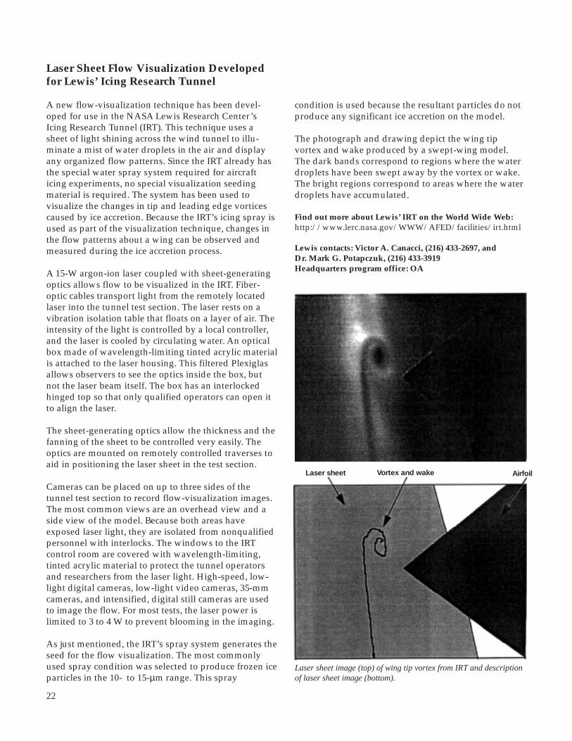
22
Laser Sheet Flow Visualization Developedfor Lewis’ Icing Research Tunnel
A new flow-visualization technique has been devel-oped for use in the NASA Lewis Research Center’sIcing Research Tunnel (IRT). This technique uses asheet of light shining across the wind tunnel to illu-minate a mist of water droplets in the air and displayany organized flow patterns. Since the IRT already hasthe special water spray system required for aircrafticing experiments, no special visualization seedingmaterial is required. The system has been used tovisualize the changes in tip and leading edge vorticescaused by ice accretion. Because the IRT’s icing spray isused as part of the visualization technique, changes inthe flow patterns about a wing can be observed andmeasured during the ice accretion process.
A 15-W argon-ion laser coupled with sheet-generatingoptics allows flow to be visualized in the IRT. Fiber-optic cables transport light from the remotely locatedlaser into the tunnel test section. The laser rests on avibration isolation table that floats on a layer of air. Theintensity of the light is controlled by a local controller,and the laser is cooled by circulating water. An opticalbox made of wavelength-limiting tinted acrylic materialis attached to the laser housing. This filtered Plexiglasallows observers to see the optics inside the box, butnot the laser beam itself. The box has an interlockedhinged top so that only qualified operators can open itto align the laser.
The sheet-generating optics allow the thickness and thefanning of the sheet to be controlled very easily. Theoptics are mounted on remotely controlled traverses toaid in positioning the laser sheet in the test section.
Cameras can be placed on up to three sides of thetunnel test section to record flow-visualization images.The most common views are an overhead view and aside view of the model. Because both areas haveexposed laser light, they are isolated from nonqualifiedpersonnel with interlocks. The windows to the IRTcontrol room are covered with wavelength-limiting,tinted acrylic material to protect the tunnel operatorsand researchers from the laser light. High-speed, low-light digital cameras, low-light video cameras, 35-mmcameras, and intensified, digital still cameras are usedto image the flow. For most tests, the laser power islimited to 3 to 4 W to prevent blooming in the imaging.
As just mentioned, the IRT’s spray system generates theseed for the flow visualization. The most commonlyused spray condition was selected to produce frozen iceparticles in the 10- to 15-µm range. This spray
Laser sheet image (top) of wing tip vortex from IRT and descriptionof laser sheet image (bottom).
Vortex and wakeLaser sheet Airfoil
condition is used because the resultant particles do notproduce any significant ice accretion on the model.
The photograph and drawing depict the wing tipvortex and wake produced by a swept-wing model.The dark bands correspond to regions where the waterdroplets have been swept away by the vortex or wake.The bright regions correspond to areas where the waterdroplets have accumulated.
Find out more about Lewis’ IRT on the World Wide Web:http://www.lerc.nasa.gov/WWW/AFED/facilities/irt.html
Lewis contacts: Victor A. Canacci, (216) 433-2697, andDr. Mark G. Potapczuk, (216) 433-3919Headquarters program office: OA

23
Gear Crack Propagation Investigation
Reduced weight is a major design goal in aircraft powertransmissions. Some gear designs incorporate thin rimsto help meet this goal. Thin rims, however, may lead tobending fatigue cracks. These cracks may propagatethrough a gear tooth or into the gear rim. A crack thatpropagates through a tooth would probably not becatastrophic, and ample warning of a failure could bepossible. On the other hand, a crack that propagatesthrough the rim would be catastrophic. Such crackscould lead to disengagement of a rotor or propellerfrom an engine, loss of an aircraft, and fatalities.
To help create and validate tools for the gear designer,the NASA Lewis Research Center performed in-houseanalytical and experimental studies to investigate theeffect of rim thickness on gear-tooth crack propagation.Our goal was to determine whether cracks grewthrough gear teeth (benign failure mode) or throughgear rims (catastrophic failure mode) for various rimthicknesses. In addition, we investigated the effect ofrim thickness on crack propagation life. A finite-element-based computer program simulated gear-toothcrack propagation. The analysis used principles oflinear elastic fracture mechanics, and quarter-point,triangular elements were used at the crack tip torepresent the stress singularity. The program had anautomated crack propagation option in which crackswere grown numerically via an automated remeshingscheme. Crack-tip stress-intensity factors wereestimated to determine crack-propagation direction.Also, various fatigue crack-growth models were usedto estimate crack-propagation life.
Experiments were performed in Lewis’ Spur GearFatigue Rig to validate predicted crack-propagationresults. Gears with various backup ratios were testedto validate crack-path predictions. Also, test gears wereinstalled with special crack-propagation gages in thetooth fillet region to measure bending-fatigue crackgrowth.
From both predictions and tests, gears with backupratios (rim thickness divided by tooth height) of 3.3 and1.0 produced tooth fractures, whereas a backup ratio of0.3 produced rim fractures. For a backup ratio of 0.5,the experiments produced rim fractures and thepredictions produced both rim and tooth fractures,depending on the initial geometry of the crack. Goodcorrelation between predicted and measured crackgrowth was achieved when the fatigue crack-closureconcept was introduced into the analysis. As the gearrim thickness decreased, the compressive cyclic stressin the gear-tooth fillet region increased. This retarded
crack growth and increased the number of crack-propagation cycles to failure.
All studies to date have been two-dimensionalanalyses; validation has been with narrow-face-widthspur gears. In the current analysis, which is beinginvestigated for three-dimensional applications ofspiral-bevel gears, data are being compared in a full-scale OH-58 helicopter main rotor transmissionapplication.
Bibliography
Lewicki, D.G.: Crack Propagation Studies to DetermineBenign or Catastrophic Failure Modes for Aerospace Thin-Rim Gears, Ph.D. Thesis, Case Western Reserve University,1995.
Lewis contact: Dr. David G. Lewicki, (216) 433-3970Headquarters program office: OA
Effect of rim thickness on gear-tooth crack-propagation path forvarious backup ratios (rim thickness divided by tooth height).Backup ratios, 3.3 (top left), 1.0 (top right), 0.5 (center left), 0.4(center right), 0.3 (bottom left), and 0.2 (bottom right).
Aeronautics

24
Study of Gear Dynamic Forces Completed
Gearbox-generated noise and vibration is objectionablein many vehicles, particularly helicopters. This noiseexcitation is caused by the load fluctuation as gear teethenter and leave mesh. In high-quality gears, a commontechnique to reduce gear noise and vibration is tomodify the tooth profile. Gear noise reduction is aNASA and U.S. Army goal, and a NASA/U.S. Armyresearch project sponsored development of geardynamics computer codes to help design quiet gears.As part of this project, a series of experiments wasperformed in the NASA Lewis Research Center’s GearNoise Rig to develop a data base of dynamic test dataand to validate the predictions of the codes for severalgear designs under a variety of test conditions.
A method was developed to use dynamic strain gagemeasurements performed on Lewis’ Gear Noise Rigto determine the forces acting between the gear teeth.Then, these dynamic force data were compared withpredictions of DANST-PC, a NASA gear dynamicscode. Tests were performed on six sets of low-contact-ratio spur gears that were identical except for differenttooth profile modifications. The figures comparemeasured and predicted dynamic tooth force underseveral load conditions. They demonstrate that theanalysis code successfully simulates the dynamicbehavior of the gears under most conditions.
This analysis code can be used by gear designers todevelop improved tooth profiles for quieter gears.Experiments continue to extend the data base toinclude high-contact-ratio gears and nonstandard toothprofiles. These promise further improvements in gearperformance.
Bibliography
Oswald, F.B.; and Townsend, D.P.: Influence of Tooth ProfileModification on Spur Gear Dynamic Tooth Strain. AIAAPaper 95-3050 (NASA TM-106952), 1995.
Oswald, F.B., et al.: Measuring Dynamic Forces in Spur Gearsto Validate a Gear Dynamics Code. To be published as aNASA TM, 1996.
Lewis contact: Fred B. Oswald, (216) 433-3957Headquarters program office: OA
Pre
dic
ted
fo
rce,
N
0Measured force, N
0
2000
3000
3500
500 1000 1500 2000 2500 3000 3500
2500
1000
500
1500
0
2000
3000
3500
2500
1000
500
1500
30Roll angle, deg
0
2000
3000
3500
28 26 24 22 20 18 16 14 12
2500
1000
500
1500
Fo
rce,
N
Left: Comparison of measured and predicted maximum dynamic tooth force for 6 gear designs and at 36 test conditions. Right: Measured(top) and predicted (bottom) dynamic tooth force for unmodified gear (4000 rpm and 5 different torque levels).

25
Code to Optimize Load Sharing ofSplit-Torque Transmissions Applied tothe Comanche Helicopter
Most helicopters now in service have a transmissionwith a planetary design. Studies have shown that somehelicopters would be lighter and more reliable if theyhad a transmission with a split-torque design instead.However, a split-torque design has never been used bya U.S. helicopter manufacturer because there has beenno proven method to ensure equal sharing of the loadamong the multiple load paths. The Sikorsky/Boeingteam has chosen to use a split-torque transmission forthe U.S. Army’s Comanche helicopter, and SikorskyAircraft is designing and manufacturing the transmis-sion. To help reduce the technical risk of fielding thishelicopter, NASA and the Army have done the researchjointly in cooperation with Sikorsky Aircraft. A theorywas developed that equal load sharing could beachieved by proper configuration of the geartrain, anda computer code was completed in-house at the NASALewis Research Center to calculate this optimalconfiguration.
The prototype split-torque transmission for theComanche helicopter was designed and built before thenew theory and computer code were available, and themeasured loads on the four final drive gears of theprototype were not equal. In fact, one of the gears wasloaded beyond the allowable design load. The newtheory and computer code correctly predicted the trendof the loads for the prototype design, and the code was
applied to calculate small, but important, designchanges to theoretically balance the loads on all fourgears. The code calculates how elastic deformationsaffect the relative amount of load carried in each loadpath. The deformations that were considered in theanalysis were tooth bending, gearshaft twist, gearshaftbowing, housing deflections, and the Hertzian defor-mations at bearing rolling element and racewaycontacts. The design changes calculated to accommo-date the deformations were manufactured, and the testof the redesigned transmission proved that the loadsharing was greatly improved. As shown in the figure,the loads on the four final drive gears are now nearlyequal, and all loads are less than the allowable designload. A significant amount of development time andmoney was saved by applying the analysis to achievegood load sharing with only one design iteration.
The new theory and computer code have been valida-ted, and a patent application has been submitted forthis technology with Government and Sikorskypersonnel as coinventors. We plan to continue tosupport Sikorsky Aircraft with transmission tech-nology from Lewis and the Army as needed to bringthe Comanche gearbox design to maturity.
Lewis contact: Timothy L. Krantz, (216) 433-3580Headquarters program office: OA
Aeronautics
Measurements of loads on the four final drive gears prove the new theory toensure load sharing.

26
Face Gear Technology for Aerospace PowerTransmission Progresses
The use of face gears in an advanced rotorcraft trans-mission design was first proposed by the McDonnellDouglas Helicopter Company during their contractedeffort with the U.S. Army under the AdvancedRotorcraft Transmission (ART) program. Face gearswould be used to turn the corner between the hori-zontal gas turbine engine and the vertical output rotorshaft—a function currently done by spiral bevel gears.This novel gearing arrangement would substantiallylower the drive system weight partly because a facegear mesh would be used to split the input powerbetween two output gears. However, the use offace gears and their ability to operate successfullyat the speeds and loads required for an aerospaceenvironment was unknown. Therefore a proof-of-concept phase with an existing test stand at the NASALewis Research Center was pursued. Hardware wasdesigned that could be tested in Lewis’ Spiral BevelGear Test Rig.
The initial testing indicated that the face gear mesh wasa feasible design that could be used at high speeds andload. Surface pitting fatigue was the typical failuremode, and that could lead to tooth fracture. An interimproject was conducted to see if slight modifications tothe gear tooth geometry or an alternative heat treatingprocess could overcome the surface fatigue problems.From the initial and interim tests, it was apparent thatfor the surface fatigue problems to beovercome the manufacturing processused for this component would have tobe developed to the level used forspiral bevel gears. The current state ofthe art for face gear manufacturingrequired using less than optimal gearmaterials and manufacturingtechniques because the surface of thetooth form does not receive finalfinishing after heat treatment as it doesfor spiral bevel gears. This resulted inless than desirable surface hardnessand manufacturing tolerances.
An Advanced Research and ProjectsAgency (ARPA) Technology Reinvest-ment Project has been funded to inves-tigate the effects of manufacturingprocess improvements on the opera-ting characteristics of face gears. Theprogram is being conducted withMcDonnell Douglas Helicopter Co.,
Lucas Western Inc., the University of Illinois at Chicago,and a NASA/U.S. Army team. The goal of the project isdevelop the grinding process, experimentally verify theimprovement in face gear fatigue life, and conduct afull-scale helicopter transmission test. The theory andmethodology to grind face gears has been completed,and manufacture of the test hardware is ongoing.Experimental verification on test hardware is scheduledto begin in fiscal 1996.
Bibliography
Handschuh, R.; Lewicki, D.; and Bossler, R.: ExperimentalTesting of Prototype Face Gears for Helicopter Transmissions.NASA TM-105434, 1992.
Heath, G.F.; and Bossler, R.B.: Advanced RotorcraftTransmission (ART) Program. Final Report. NASACR-191057, 1993.
Lewis contacts: Dr. David G. Lewicki, (216) 433-3970, andDr. Robert F. Handschuh, (216) 433-3969Headquarters program office: OA
Face gear test hardware.
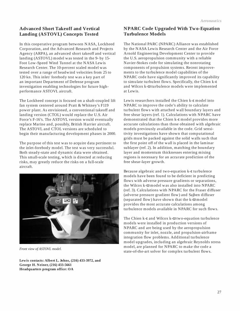
27
Advanced Short Takeoff and VerticalLanding (ASTOVL) Concepts Tested
In this cooperative program between NASA, LockheedCorporation, and the Advanced Research and ProjectsAgency (ARPA), an advanced short takeoff and verticallanding (ASTOVL) model was tested in the 9- by 15-Foot Low-Speed Wind Tunnel at the NASA LewisResearch Center. The 10-percent scaled model wastested over a range of headwind velocities from 25 to120 kn. This inlet/forebody test was a key part ofan important Department of Defense programinvestigation enabling technologies for future high-performance ASTOVL aircraft.
The Lockheed concept is focused on a shaft-coupled liftfan system centered around Pratt & Whitney’s F119power plant. As envisioned, a conventional takeoff andlanding version (CTOL) would replace the U.S. AirForce’s F-16’s. The ASTOVL version would eventuallyreplace Marine and, possibly, British Harrier aircraft.The ASTOVL and CTOL versions are scheduled tobegin their manufacturing development phases in 2000.
The purpose of this test was to acquire data pertinent tothe inlet-forebody model. The test was very successful.Both steady-state and dynamic data were obtained.This small-scale testing, which is directed at reducingrisks, may greatly reduce the risks on a full-scaleaircraft.
Aeronautics
NPARC Code Upgraded With Two-EquationTurbulence Models
The National PARC (NPARC) Alliance was establishedby the NASA Lewis Research Center and the Air ForceArnold Engineering Development Center to providethe U.S. aeropropulsion community with a reliableNavier-Stokes code for simulating the nonrotatingcomponents of propulsion systems. Recent improve-ments to the turbulence model capabilities of theNPARC code have significantly improved its capabilityto simulate turbulent flows. Specifically, the Chien k-εand Wilcox k-ω turbulence models were implementedat Lewis.
Lewis researchers installed the Chien k-ε model intoNPARC to improve the code’s ability to calculateturbulent flows with attached wall boundary layers andfree shear layers (ref. 1). Calculations with NPARC havedemonstrated that the Chien k-ε model provides moreaccurate calculations than those obtained with algebraicmodels previously available in the code. Grid sensi-tivity investigations have shown that computationalgrids must be packed against the solid walls such thatthe first point off of the wall is placed in the laminarsublayer (ref. 2). In addition, matching the boundarylayer and momentum thicknesses entering mixingregions is necessary for an accurate prediction of thefree shear-layer growth.
Because algebraic and two-equation k-ε turbulencemodels have been found to be deficient in predictingflows with adverse pressure gradients or separations,the Wilcox k-ω model was also installed into NPARC(ref. 3). Calculations with NPARC for the Fraser diffuser(adverse pressure gradient flow) and Sajben diffuser(separated flow) have shown that the k-ω modelprovides the most accurate calculations amongturbulence models available in NPARC for such flows.
The Chien k-ε and Wilcox k-ω two-equation turbulencemodels were installed in production versions ofNPARC and are being used by the aeropropulsioncommunity for inlet, nozzle, and propulsion-airframeintegration flow problems. Additional turbulencemodel upgrades, including an algebraic Reynolds stressmodel, are planned for NPARC to make the code astate-of-the-art solver for complex turbulent flows.
Front view of ASTOVL model.
Lewis contacts: Albert L. Johns, (216) 433-3972, andGeorge H. Neiner, (216) 433-5661Headquarters program office: OA

28
0 600 1200
0
800
0.5
400200–1.0
–0.5
1.0
Ver
tical
po
sitio
n in
mix
ing
sect
ion,
Y/H
1000Axial velocity, ft/s
Gilbert-Hill dataChien k-εThomas
0 15 20
0
0.003
105–0.001
0.001
0.004
Ski
n fr
ictio
n co
effic
ient
,C
f
Axial position in diffuser, in.
Baldwin-LomaxChien k-εWilcox k-v
Fraser data
0.002
ω
Top: Velocity profiles for an ejector nozzle flow. Bottom: Skinfriction for the Fraser subsonic diffuser.
References
1. Georgiadis, N.J.; Chitsomboon, T.; and Zhu, J.: Modification of the Two-Equation Turbulence Model in NPARC to a Chien Low Reynolds Number k-ε Formulation. NASA TM-106710, 1994.
2. Georgiadis, N.J.; Dudek, J.C.; and Tierney, T.P.: Grid Resolution and Turbulent Inflow Boundary Condition Recommendations for NPARC Calculations. AIAA Paper 95-2613 (NASA TM-106959), 1995.
3. Yoder, D.; Georgiadis, N.J.; and Orkwis, P.: Implementation of a Two-Equation k-ω Turbulence Model in NPARC. AIAA Paper 96-0383, 1995.
For more information about the NPARC Alliance, visit theirsite on the World Wide Web:http://info.arnold.af.mil/nparc/index.html
Lewis contact: Nicholas J. Georgiadis, (216) 433-3958Headquarters program office: OA
Mixing Process in Ejector Nozzles Studied atLewis’ Aero-Acoustic Propulsion Laboratory
The NASA Lewis Research Center has been studyingmixing processes in ejector nozzles for its High SpeedResearch (HSR) Program. This work is directed atfinding ways to minimize the noise of a future super-sonic airliner. Much of the noise such an airplanewould generate would come from the nozzle, where ahot, high-speed jet exits the engine.
Several different nozzle configurations were used toproduce nozzle systems with different acoustical andaerodynamic characteristics. The acoustical propertieswere measured by an array of microphones in ananechoic chamber, and the aerodynamics weremeasured by traditional pressure and temperatureinstruments as well as by Laser Doppler Velocimetry(LDV), a technique for visualizing the airflow patternwithout disturbing it. These measurements were puttogether and compared for different configurations toexamine the relationships between mixing and noisegeneration.
Shown in the photo is the mixer-ejector nozzle withthe installed flow-visualization windows (foreground),the optical equipment and the supporting structure forthe Laser Doppler Velocimetry flow visualization(midfield), and the sound-absorbing wedges used tocreate an anechoic environment for acoustic testing(background).
The High Speed Research Program is a NASA-fundedeffort, in cooperation with the U.S. aerospace indus-try, to develop enabling technologies for a futuresupersonic airliner. One of the technological barriersbeing addressed is noise generated during near-airportoperation. The mixer-ejector nozzle concept is beingexamined as a way to reduce jet noise while maintain-ing thrust. Ambient air is mixed with the high-velocityengine exhaust to reduce the jet velocity and hence thenoise generated by the jet.
The model was designed and built by Pratt & Whitneyunder NASA contract. The test, completed in June 1995,was conducted in Lewis’ Aero-Acoustic PropulsionLaboratory.

29
Aeronautics
Ejector nozzle being used to study mixing processes for noise reduction.
F119 Nozzle Flaps Tested at Lewis’ CE-22Facility
The next generation of aircraft fighters requires higherengine performance and enhanced stealth character-istics for air superiority. A Lockheed-Martin/Boeingaircraft with a Pratt & Whitney F119 engine was selec-ted by the Air Force for the next advanced tacticalfighter (ATF). As part of this program, the NASA LewisResearch Center entered into a cooperative test pro-gram with Pratt & Whitney along with the Air Forceto study the performance for various advanced nozzleconcepts for the F119 engine. The area of interest wasto measure the internal performance (both thrust andflow coefficients) of nozzle flaps redesigned for lowobservability with minimal performance loss.
The experimental program was successfully completedMay 1995 in Lewis’ CE-22 facility. The models weretested over a wide range of geometric variations andnozzle pressure ratios. Results confirmed that theredesigned nozzle flaps had an insignificant effect onthe thrust performance and that the resulting flowpatterns should not be a problem in the cooling flowdesign. The results also agreed well with Pratt &Whitney’s computational fluid dynamics analysis. Thedata obtained from this test were added to the currentdata base to help validate other performance predictionmethodology.
Lewis contact: David W. Lam, (216) 433-8875Headquarters program office: OA
F119 nozzle in CE-22 test facility.
For more information about Lewis’ Aero-AcousticPropulsion Laboratory and the High Speed ResearchProgram, visit our sites on the World Wide Web:http://www.lerc.nasa.gov/WWW/AFED/facilities/aapl.htmlhttp://www.lerc.nasa.gov/WWW/HSR/
Lewis contact: John D. Wolter, (216) 433-3941Headquarters program office: OA

30
Prediction Capability for Transonic NozzleAfterbodies Improved
Under the High Speed Research (HSR) Program, theNASA Lewis Research Center, the NASA LangleyResearch Center, and the aerospace industry have beendeveloping exhaust nozzle concepts for a future HighSpeed Civil Transport (HSCT). This 300-passengeraircraft, which is envisioned for the year 2005, wouldcruise supersonically at speeds of Mach 2.4. For such anaircraft to be both economically viable and environmen-tally acceptable, the exhaust nozzles must combinehighly efficient operation throughout the flight envel-ope with low noise levels at takeoff.
The initial phase of the HSR Program focused onenvironmental challenges, with nozzle-related researchemphasizing the reduction of takeoff noise. The effortproduced nozzle designs that not only meet but surpassHSR noise-reduction goals. The next step in the designprocess is to address the nozzle’s performance through-out the aircraft’s mission and integrate it with the restof the propulsion system. To evaluate nozzle conceptsfor all flight conditions, engineers rely on empiricaldata bases obtained through extensive wind tunneltests. However, the current HSR nozzles are a rectan-gular (two-dimensional) design, and this type of nozzleis not well represented in the existing data base.Therefore, the current methods for predicting nozzleperformance are inadequate. This is especiallytroublesome at transonic (near Mach 1)conditions where the drag on thenozzle afterbody (boattail) can be ashigh as 25 percent of the thrustproduced.
For a more accurate analysis attransonic speeds, a two-dimensionalafterbody data base was needed.Because of the expense, time require-ments, and difficulties in testing atthese Mach numbers, wind tunnel testswere not feasible. A team composed ofresearchers from Lewis, Langley, andMcDonnell Douglas created a two-dimensional data base using computa-tional fluid dynamics. First, each groupvalidated their computational fluiddynamics code against existing experi-mental data to gain confidence in thecode’s results. Next, the organizationsanalyzed several configurations, andthe results were used to create the newdata base. Then, the analysis methods
were updated to account for the effects of two-dimensional nozzles. This will result in a more accurateanalysis of the propulsion system for the High SpeedCivil Transport.
Researchers at Lewis used the NPARC computationalfluid dynamics code in their portion of the analysis.This code is a general-purpose, full Navier-Stokessolver that is supported through a joint effort betweenLewis and the Air Force’s Arnold EngineeringDevelopment Center. The analyses were run on bothLewis’ Cray Y-MP and the Aeronautics ConsolidatedSupercomputing Facility’s Cray C-90 located at theNASA Ames Research Center. Lewis producedseven calculations for the data base. Results of theGovernment-industry team correlated well with eachother as well as with the accepted theory.
For more information about the HSR Program and NPARC,visit their sites on the World Wide Web:http://www.lerc.nasa.gov/WWW/HSR/http://info.arnold.af.mil/nparc/index.html
Lewis contact: James R. DeBonis, (216) 433-6581Headquarters program office: OA
NPARC code prediction of Mach number contours about a transonic nozzle afterbody.

31
Thin-Film Thermocouple TechnologyDemonstrated for Reliable Heat TransferMeasurements
Exploratory work is in progress to apply thin-filmthermocouples to localized heat transfer measurementson turbine engine vanes and blades. The emerging thin-film thermocouple technology shows great potential toimprove the accuracy of local heat transfer measure-ments. With conventional imbedded thermocouples,heat-transfer measurements on the thin walls of cooledturbine blades have a high uncertainty because ofunavoidable flow and heat-path perturbations causedby the bulky thermocouples and lead wires. Thin-filmthermocouples offer an ideal solution for blade andvane surface temperature measurements because theyguarantee virtually no perturbation of the heat pathand blade wall thickness or of the coolant and gas flowpatterns. However, early attempts to use thin-filmsensors were not fully successful mainly because ofproblems with the thin-film-to-lead-wire connections.
To verify and master the experimental methodology ofthin-film thermocouples, the NASA Lewis ResearchCenter conducted a proof-of-concept experiment in acontrolled environment before applying the thin-filmsensors to turbine tests. The test article consisted of aflat plate with an internally cooled narrow passagesubmerged into a stream of heated air. Both theexternally heated side and the internally cooled sidewere instrumented with thin-film sensors. A typicalthin-film thermocouple sensor and the instrumentedtest article are shown in the figures. A major problemwith applying thin films to electrically conductingmetal surfaces is the necessity to insulate the sensorfrom the substrate. We accomplished this by modifyingthe aluminum oxide layer. Another crucial aspect ofthin-film sensor reliability is the connection betweenthe thin-film thermocouple legs and the lead wires thatlink the sensors with data-acquisition equipment. Inour approach, the sputtered thermocouple legs werefirst connected to bare 25-µm thermocouple alloy wires,which were then connected to 0.25-mm insulatedthermocouple lead wires. This approach proved highlyreliable; no thermocouple was lost during testing.
Initial tests were conducted at Mach 0.4 and at a statictemperature of 425 K on the heated side and at Mach0.5 and a static temperature of 280 K on the cooled side;the heat flow rate was 200 kW/m2. Lewis is preparingwork with partners from industry on applying the thin-film thermocouples to turbine blades for temperaturemeasurements up to 700 K and to turbine vanes fortemperatures up to 1000 K.
Aeronautics
Constantanlayer (3 µm)
Constantanleg
Chromelleg
Chromellayer (1.5 µm)
Aluminumoxide layer(5 µm)
Nickel layer(2.5 µm)Test article
surfaceThermocouplejunction
Top: Thin-film thermocouple (type E). Bottom: Test articleinstrumented with four thin-film thermocouples.
Bibliography
Lepicovsky, J.; Bruckner, R.J; and Smith, F.A.: Applicationof Thin-Film Thermocouples to Localized Heat TransferMeasurements. AIAA Paper 95-2834 (NASA TM-107045),1995.
Lewis contact: Dr. Jan Lepicovsky, (216) 977-1402Headquarters program office: OA

32
Effect of Brush Seals on Wave RotorPerformance Assessed
The NASA Lewis Research Center’s experimental andtheoretical research shows that wave rotor topping cansignificantly enhance gas turbine engine performancelevels. Engine-specific fuel consumption and specificpower are potentially enhanced by 15 and 20 percent,respectively, in small (e.g., 400 to 700 hp) and inter-mediate (e.g., 3000 to 5000 hp) turboshaft engines. Fur-thermore, there is potential for a 3- to 6-percent specificfuel consumption enhancement in large (e.g., 80,000 to100,000 lbf) turbofan engines (ref. 1). This wave-rotor-enhanced engine performance is accomplished withincurrent material-limited temperature constraints.
The completed first phase of experimental testinginvolved a three-port wave rotor cycle in whichmedium total pressure inlet air was divided into twooutlet streams, one of higher total pressure and one oflower total pressure. The experiment successfullyprovided the data needed to characterize viscous,partial admission, and leakage loss mechanisms.Statistical analysis indicated that wave rotor productefficiency decreases linearly with the rotor to end-wallgap, the square of the friction factor, and the square ofthe passage of nondimensional opening time. Brushseals were installed to further minimize rotor passage-to-cavity leakage. The graph shows the effect of brushseals on wave rotor product efficiency.
For the second-phase experiment, which involves afour-port wave rotor cycle in which heat is added to theBrayton cycle in an external burner, a one-dimensionaldesign/analysis code (ref. 2) is used in conjunction witha wave rotor performance optimization scheme (ref. 3)and a two-dimensional Navier-Stokes code (ref. 4). Thepurpose of the four-port experiment is to demonstrateand validate the numerically predicted four-port pres-sure ratio versus temperature ratio at pressures andtemperatures lower than those that would be encoun-tered in a future wave rotor/demonstrator engine test.Lewis and the Allison Engine Company are collabora-ting to investigate wave rotor integration in an existingturboshaft engine.
Recent theoretical efforts include simulating wave rotordynamics (e.g., startup and load-change transientanalysis, see ref. 5), modifying the one-dimensionalwave rotor code to simulate combustion internal to thewave rotor, and developing an analytical wave rotordesign/analysis tool based on macroscopic balances forparametric wave rotor/engine analysis.
Left: Brush seals have been added to the three-port rotor experiment. These seals prevent leakage from the passages to the surrounding cavitybut do not affect circumferential (i.e., passage to passage) leakage. The seals improved the performance significantly at large values of therotor to end-wall gap spacing, but they had less of an effect at small values of gap spacing. Right: Three-port wave rotor rig.

33
References
1. Welch, G.E.; Jones, S.M.; and Paxson, D.E.: Wave Rotor- Enhanced Gas Turbine Engines. AIAA Paper 95-2799 (NASA TM-106998 and ARL-TR-806), 1995.
2. Paxson, D.E.: A Comparison Between Numerically Modelled and Experimentally Measured Loss Mechanisms in Wave Rotors. AIAA Paper 93-2522 (NASA TM-106279), 1993.
3. Wilson, J.; and Paxson, D.E.: Optimization of Wave Rotors for Use as Gas Turbine Engine Topping Cycles. NASA TM-106951, 1995.
4. Welch, G.E.; and Chima, R.V.: Two-Dimensional CFD Modeling of Wave Rotor Flow Dynamics. AIAA Paper 93-3318 (NASA TM-106261), 1993.
5. Paxson, D.E.: A Numerical Model for Dynamic Wave Rotor Analysis. AIAA Paper 95-2800 (NASA TM-106997), 1995.
Lewis contacts: Dr. Jack Wilson, (216) 977-1204, andDr. Gerard E. Welch, (216) 433-8003Headquarters program office: OA
Aeronautics
Scale-Model, Low-Tip-Speed TurbofanTested at Simulated Takeoff andApproach Conditions
Tests are currently being performed in the NASA LewisResearch Center’s 9- by 15-Foot Low-Speed WindTunnel on a Pratt & Whitney designed low-tip-speedfan. The test objectives are to determine the acoustic,aerodynamic, and aeromechanical performance of thislow-speed, high-bypass-ratio fan stage. Noise reduc-tions from various combinations of engine nacelleacoustic treatments are also being obtained.
The test rig simulates full-scale engine components inscale-model size. The complete engine fan module(engine nacelle, bypass fan stage, and nozzle), athroughflow core duct, and engine acoustic treatmentwithin the nacelle are all simulated. During the testing,fan model performance is obtained from force balancesmounted internally in the model as well as by airflowmeasurements taken with duct wall and rake instru-mentation. The internal force balances consist of atwo-component rotating balance to measure thrust andtorque and a six-component static balance to measurethe drag and torque forces of the bypass stator andnacelle. Far-field acoustic measurements are obtained
by a track-mounted, axially translating microphone.The microphone makes equal-angle stops along thetraverse to obtain the noise at simulated takeoff andapproach conditions. A rotating microphone array isused in the inlet and exhaust to obtain induct noisemeasurements for source diagnostic research.
The data obtained during this test will be used byNASA and Pratt & Whitney research engineers toascertain the benefits of this lower tip speed, high-bypass-ratio fan stage. They will validate computerdesign and analysis codes used for both fan stagecomponents and acoustic treatment. Comparison of thedata with predictions from the computer codes willindicate where these codes can be improved for betterperformance predictions, lower noise, and better enginedesigns.
Low-tip-speed fan installed in wind tunnel.
Lewis contacts: Dr. James H. Dittmar, (216) 433-3921, andRobert J. Jeracki, (216) 433-3917Headquarters program office: OA
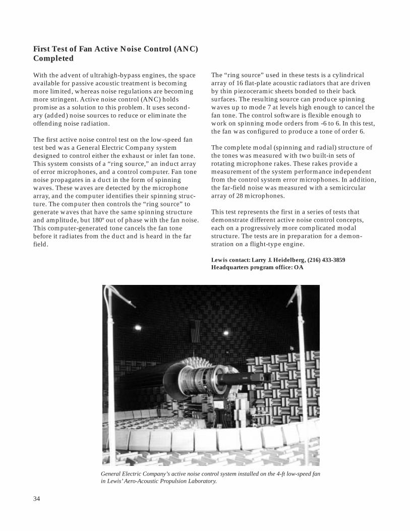
34
First Test of Fan Active Noise Control (ANC)Completed
With the advent of ultrahigh-bypass engines, the spaceavailable for passive acoustic treatment is becomingmore limited, whereas noise regulations are becomingmore stringent. Active noise control (ANC) holdspromise as a solution to this problem. It uses second-ary (added) noise sources to reduce or eliminate theoffending noise radiation.
The first active noise control test on the low-speed fantest bed was a General Electric Company systemdesigned to control either the exhaust or inlet fan tone.This system consists of a “ring source,” an induct arrayof error microphones, and a control computer. Fan tonenoise propagates in a duct in the form of spinningwaves. These waves are detected by the microphonearray, and the computer identifies their spinning struc-ture. The computer then controls the “ring source” togenerate waves that have the same spinning structureand amplitude, but 180º out of phase with the fan noise.This computer-generated tone cancels the fan tonebefore it radiates from the duct and is heard in the farfield.
The “ring source” used in these tests is a cylindricalarray of 16 flat-plate acoustic radiators that are drivenby thin piezoceramic sheets bonded to their backsurfaces. The resulting source can produce spinningwaves up to mode 7 at levels high enough to cancel thefan tone. The control software is flexible enough towork on spinning mode orders from -6 to 6. In this test,the fan was configured to produce a tone of order 6.
The complete modal (spinning and radial) structure ofthe tones was measured with two built-in sets ofrotating microphone rakes. These rakes provide ameasurement of the system performance independentfrom the control system error microphones. In addition,the far-field noise was measured with a semicirculararray of 28 microphones.
This test represents the first in a series of tests thatdemonstrate different active noise control concepts,each on a progressively more complicated modalstructure. The tests are in preparation for a demon-stration on a flight-type engine.
Lewis contact: Larry J. Heidelberg, (216) 433-3859Headquarters program office: OA
General Electric Company’s active noise control system installed on the 4-ft low-speed fanin Lewis’ Aero-Acoustic Propulsion Laboratory.

35
Subsonic Jet Noise Reduced With ImprovedInternal Exhaust Gas Mixers
Aircraft noise pollution is becoming a major environ-mental concern for the world community. The FederalAviation Administration (FAA) is responding to thisconcern by imposing more stringent noise restrictionsfor aircraft certification then ever before to keep theU.S. industry competitive with the rest of the world.At the NASA Lewis Research Center, attempts areunderway to develop noise-reduction technology fornewer engines and for retrofitting existing engines sothat they are as quiet as (or quieter than) required.Lewis conducted acoustic and Laser DopplerVelocimetry (LDV) tests using Pratt & Whitney’sInternal Exhaust Gas Mixers (IEGM). The IEGM’s mixthe core flow with the fan flow prior to their commonexhaust.
All tests were conducted in Lewis’ Aero-AcousticPropulsion Laboratory—a semihemispheric dome opento the ambient atmosphere. This was the first timeLaser Doppler Velocimetry was used in such a facilityat Lewis. Jet exhaust velocity and turbulence and theinternal velocity fields were detailed. Far-field acousticswere also measured. Pratt & Whitney provided 1/7thscale model test hardware (a 12-lobe mixer, a 20-lobemixer, and a splitter) for 1.7 bypass ratio engines, andNASA provided the research engineers, test facility, andtest time. The Pratt & Whitney JT8D-200 engine powerconditions were used for all tests.
The Laser Doppler Velocimetry measurements at thecommon exhaust nozzle showed the presence of high-velocity regions at the nozzle exit which directlycorresponded to the mixer lobes (see figure). The12-lobe mixer had 12 high-velocity regions, andthe 20-lobe mixer had 20. The radial mean velocitybetween the mixers was nearly equivalent, but it wasapproximately 300 ft/sec slower than the radial meanvelocity with the splitter. The turbulence intensity,with respect to the centerline velocity, reached about12 percent between the core and the fan shear layerfor the splitter. The 20-lobe mixer had about the sameintensity, but the 12-lobe mixer had about 16-percentturbulence intensity.
The acoustic data showed that both mixers were quieterthan the splitter nozzle. This is a direct consequence ofreductions in the mean jet exhaust velocities. Themixing between the core and the fan within the IEGMcreated the high-frequency noise. The mixing noise forthe 12-lobe mixer was higher than that for the splitter,and the 20-lobe mixer had the quietest mixing noise.
Aeronautics
When scaled to constant full-scale thrust, the 20-lobemixer was approximately 7.5 effective perceived noisedecibels (EPNdB) quieter than the splitter andapproximately 2 EPNdB quieter than the 12-lobe mixer.Efforts are continuing to make these IEGM’s reach theFederal Aviation Administration’s noise limits. Lewis,in cooperation with industry, is continuing to advancethe research and technology to quiet U.S. aircraftengines.
For more information about Laser Doppler Velocimetry andLewis’ Aero-Acoustic Propulsion Laboratory, visit Lewis onthe World Wide Web:http://www.lerc.nasa.gov/WWW/OptInstr/ldv.htmlhttp://www.lerc.nasa.gov/WWW/AFED/facilities/aapl.html
Lewis contact: Naseem H. Saiyed, (216) 433-6736(E-Mail: [email protected])Headquarters program office: OA
Laser Doppler Velocimetry data from the subsonic jet noiseprogram.
36
Aeropropulsion Facilities andExperiments
Drive Motor Improved for 8- by 6-FootSupersonic Wind Tunnel/9- by 15-FootLow-Speed Wind Tunnel Complex
An operational change made recently in the drivemotor system for the 8- by 6-Foot Supersonic WindTunnel (8x6 SWT)/9- by 15-Foot Low-Speed WindTunnel (9x15 LSWT) complex resulted in dramaticpower savings and expanded operating range.
The 8x6 SWT/9x15 LSWT complex offers a uniquecombination of wind tunnel conditions for both high-and low-speed testing. Prior to the work discussed inthis article, the 8- by 6-ft test section offered airflowsranging from Mach 0.36 to 2.0. Subsonic testing wasdone in the 9-ft high, 15-ft wide test area in the returnleg of the facility. The air speed in this test section canrange from 0 to 175 mph (Mach 0.23).
In the past, we varied the air speed by using a combi-nation of the compressor speed and the position of thetunnel flow-control doors. When very slow speedswere required in the 9x15 LSWT, these large tunnelflow-control doors might be very nearly full open,bleeding off large quantities of air, even with the drivesystem operating at its previous minimum speed ofabout 510 rpm. Power drawn during this mode ofoperation varied between 15 and 18 MW/hr, but clearlymuch of this power was not being used to provide airthat would be used for testing in the test section. Theair exiting these large doors represented wasted power.
Early this year, the facility’s tunnel drive system wasrun on one motor instead of three to see if lower drivespeeds could be achieved that would, in turn, result inlarge power savings because unnecessary air would notbe blown out of the flow-control doors unnecessarily. Inaddition, if the drive could be run slower, then slowerspeeds would also be possible in the 8x6 SWT testsection as an added benefit.
Results of the first tests performed early last yearshowed that in fact the drive, when operating on onlyone motor, actually reached a steady-state speed of only337 rpm and drew an amazingly small 6 MW/hr ofelectrical power. During daytime operation of the drive,this meant that it would be possible to save as much as10 MW/hr, or nearly $600 per hour of operation, formany of the 9x15 LSWT’s testing regimes.
An added benefit of this power-saving venture was thatsince the 8x6 SWT and 9x15 LSWT are indeed on a com-mon loop, if the compressor is slowed down to benefitthe 9x15 LSWT, then the air moving through the 8x6SWT is also moving slower than ever before. In fact,testing has proven that the 8x6 SWT can now achieveMach 0.25, whereas its previous lower limit was Mach0.36. This added benefit has attracted additionalcustomers.
Find out more about the 8- by 6-Foot Supersonic WindTunnel and the 9- by 15-Foot Low-Speed Wind Tunnel onthe World Wide Web:http://www.lerc.nasa.gov/WWW/AFED/facilities/8x6.htmlhttp://www.lerc.nasa.gov/WWW/AFED/facilities/9x15.html
Lewis contact: Robert R. Smalley, (216) 433-5743Headquarters program office: OA

37
Aeronautics
Testing Efficiency Improved by Addition ofRemote Access Control Room
Because researchers need prompt access to test dataand information from testing in aeropropulsionfacilities, offsite research engineers usually travel to bepresent in the facility control room during testing.These travel costs can become quite high for extendedtest entries. The NASA Lewis Research Center’sRemote Access Control Room (RACR) uses off-the-shelfvideo conferencing software integrated with existingfacility data systems to provide access to the test databy networking from virtually anywhere in the country.The system allows research engineers in remote loca-tions to participate in tests and monitor data in realtime just as if they were present in the control room.
The concept of remote access to test data is not a newone at Lewis, and access to data has been provided inmany different ways. The objective of each solution wasto get the data to researchers as quickly as possible toexpedite testing. The RACR set out to provide theremote location with all the real-time tools available inthe control room. Unlike other implementations, theRACR displays the data as it is being acquired (onceper second updates). This includes tabular andgraphical data from the steady-state and dynamic datasystems. In addition, video data from schlieren,pressure-sensitive paint, or sheet laser systems areincluded, as well as a video confer-encing system to facilitate communi-cations between the two locations. Byintegrating all these tools on a singleworkstation, the engineer at the remotelocation can participate in the test inthe same manner as the engineers atthe facility.
RACR has already reduced the travel required tosupport a test. This is increasingly important whenbudgets are shrinking and the number of industrycustomers participating is increasing, such as in theHigh Speed Research (HSR) Program. An added benefitof such a system is that additional engineers, whowould not have traveled to the test site, can participateat the remote location. This could increase the level ofsupport and improve testing efficiency for tests that usethe Remote Access Control Room. Lewis is planning toexpand this capability and provide the service inseveral other aeropropulsion facilities.
Lewis contact: Robert R. Smalley, (216) 433-5743Headquarters program office: OA
Remote Access Control Room being used in a recent test at the Abe Silverstein 10- by10-Foot Supersonic Wind Tunnel.

38
Interdisciplinary Technology Office
Accomplishments
• This was the first high-data-rate experiment to use ACTS.• It was the first experiment to provide end-to-end ATM connectivity across the United States.• Computational fluid dynamics simulation results were used to validate experimental data from Lewis’ 10- by 10-Foot Supersonic Wind Tunnel. Computa- tional fluid dynamics simulations and windtunnel tests at Lewis were evaluated and controlled simultaneously from the same room at Boeing Corporation in Seattle.• Reportedly, Lewis was the first site in the United States to deploy the high-performance gigabit router (“GigaRouter”) from NETSTAR.• Lewis was the first site to use the Bus Based Gateway (BBG) developed by Cray Research, Inc. The BBG, which was designed and developed for this experi- ment, is now commercially available from Cray Research, Inc., as a high-performance parallel interface (HiPPI)-ATM/SONET adapter.• Bellcore designed and developed the traffic processor for this experiment. This processor can collect ATM cell-level statistics and shape traffic on the basis of
Lewis/ACTS/Boeing Experiment Demon-strates Gigabit Application Using ACTS
The objective of this project was to demonstrate asatellite-based gigabit application using the AdvancedCommunications Technology Satellite (ACTS).
To achieve this objective, a series of numericalexperiments were conducted to develop an engine inletcontrol system for the High Speed Research (HSR)Program. An inlet simulator was run on the NASALewis Research Center’s Cray YMP supercomputer butwas controlled by Boeing Corporation in Seattle,Washington. Flow visualization information wastransported via ACTS to the remote site for displayon a high-performance, three-dimensional graphicsworkstation. This enabled control system designparameters to be varied for rapid evaluation of theintegrated inlet/control system performance. Theexperimental ACTS network allowed remote access ofNASA’s distributed engine simulation application toaerospace manufacturers.
Synchronous optical networks (SONET)/asynchronoustransfer mode (ATM) traffic studies were performed onthis unique experimental network to evaluate thenetwork performance. The experimental SONET/ATMnetwork’s performance for this and other applicationswas characterized experimentally.
Layout of Lewis/ACTS/Boeing experiment.

39
specific algorithms. A more refined version that supports OC48 speeds is being built for the NECTAR project.
Significance of the Work
The Lewis/ACTS/Boeing experiment
• Reduced the amount of wind tunnel test time required to develop inlet control systems for high- speed engines• Supported the High Speed Research Project inlet downselect milestone at the end of 1995• Assessed the effect of the propagation delay on the performance of distributed computing applications• Identified key issues in developing reliable, high- speed communication transfer protocols for aerospace applications
For more information about this experiment, visit our siteon the World Wide Web:http://www.lerc.nasa.gov/WWW/NPSS/html/npss_bellcore.html
Lewis contact: Isaac López, (216) 433-5893Headquarters program office: OA (HPCCO)
Heart Pump Design for Cleveland ClinicFoundation
Through a Lewis CommTech Program project withthe Cleveland Clinic Foundation, the NASA LewisResearch Center is playing a key role in the design anddevelopment of a permanently implantable, artificialheart pump assist device. Known as the InnovativeVentricular Assist System (IVAS), this device will takeon the pumping role of the damaged left ventricle ofthe heart. The key part of the IVAS is a nonpulsatile(continuous flow) artificial heart pump with centrifugalimpeller blades, driven by an electric motor. Lewis ispart of an industry and academia team, led by the OhioAerospace Institute (OAI), that is working with theCleveland Clinic Foundation to make IVAS a reality.This device has the potential to save tens of thousandsof lives each year, since 80 percent of heart attackvictims suffer irreversible damage to the left ventricle,the part of the heart that does most of the pumping.
Impeller blade design codes and flow-modeling ana-lytical codes will be used in the project. These codeswere developed at Lewis for the aerospace industrybut will be applicable to the IVAS design project. The
Lewis/Cleveland Clinic Foundation heart pump. Top: photo,Bottom: sketch showing placement.
Aeronautics
TETS Secondary coil
Outflow conduit
Pacemaker/controller
Pump
Inflow conduit
Motor drive circuit
Internal battery
"Published with permission of The Cleveland Clinic Foundation"

40
analytical codes, which currently simulate the flowthrough the compressor and pump systems, will beused to simulate the flow within the blood pump in theartificial heart assist device. The InterdisciplinaryTechnology Office heads up Lewis’ efforts in the IVASproject. With the aid of numerical modeling, the bloodpump will address many design issues, including somefluid-dynamic design considerations that are unique tothe properties of blood. Some of the issues that will beaddressed in the design process include hemolysis,deposition, recirculation, pump efficiency, rotor thrustbalance, and bearing lubrication. Optimum pumpingsystem performance will be achieved by modeling allthe interactions between the pump components. Theinteractions can be multidisciplinary and, therefore, areinfluenced not only by the fluid dynamics of adjacentcomponents but also by thermal and structural effects.
Lewis-developed flow-modeling codes to be used inthe pump simulations will include a one-dimensionalcode (ref. 1) and an incompressible three-dimensionalNavier-Stokes flow code (ref. 2). These codes willanalyze the prototype pump designed by the ClevelandClinic Foundation. With an improved understanding ofthe flow phenomena within the prototype pump,design changes to improve the performance of thepump system can be verified by computer prior tofabrication in order to reduce risks. The use of Lewisflow modeling codes during the design and develop-ment process will improve pump system performanceand reduce the number of prototypes built in thedevelopment phase.
The first phase of the IVAS project is to fully developthe prototype in a laboratory environment that uses awater/glycerin mixture as the surrogate fluid tosimulate blood. A later phase of the project will includetesting in animals for final validation. Lewis will beinvolved in the IVAS project for 3 to 5 years.
References
1. Veres, J.P.: Centrifugal and Axial Pump Design and Off- Design Performance Prediction. NASA TM-106745, 1995.
2. Hah, C.: Calculation of Three-Dimensional Viscous Flows in Turbomachinery With an Implicit Relaxation Method. J. Propulsion, Sept.-Oct., vol. 3, no. 5, 1987.
Lewis contact: Joseph P. Veres, (216) 433-2436Headquarters program office: OA (HPCCO)
Coupled Aerodynamic-Thermal-Structural(CATS) Analysis
Coupled Aerodynamic-Thermal-Structural (CATS)Analysis is a focused effort within the NumericalPropulsion System Simulation (NPSS) program tostreamline multidisciplinary analysis of aeropropulsioncomponents and assemblies. Multidisciplinary analysisof axial-flow compressor performance has been selectedfor the initial focus of this project. CATS will permitmore accurate compressor system analysis by enablingusers to include thermal and mechanical effects as anintegral part of the aerodynamic analysis of thecompressor primary flowpath. Thus, critical details,such as the variation of blade tip clearances and thedeformation of the flowpath geometry, can be moreaccurately modeled and included in the aerodynamicanalyses. The benefits of this coupled analysis capabil-ity are (1) performance and stall line predictions areimproved by the inclusion of tip clearances and hotgeometries, (2) design alternatives can be readilyanalyzed, and (3) higher fidelity analysis by researchersin various disciplines is possible. The goals for thisproject are a 10-percent improvement in stall marginpredictions and a 2:1 speed-up in multidisciplinaryanalysis times.
Working cooperatively with Pratt & Whitney, the LewisCATS team defined the engineering processes andidentified the software products necessary for stream-lining these processes. The basic approach is tointegrate the aerodynamic, thermal, and structuralcomputational analyses by using data managementand Non-Uniform Rational B-Splines (NURBS) baseddata mapping. Five software products have beendefined for this task: (1) a primary flowpath datamapper, (2) a two-dimensional data mapper, (3) adatabase interface, (4) a blade structural pre- andpostprocessor, and (5) a computational fluid dyna-mics code for aerothermal analysis of the drum rotor.
Thus far (1) a cooperative agreement has been estab-lished with Pratt & Whitney, (2) a Primary FlowpathData Mapper has been prototyped and delivered toGeneral Electric Aircraft Engines and Pratt &Whitneyfor evaluation, (3) a collaborative effort has beeninitiated with the National Institute of Standards andTesting to develop a Standard Data Access Interface,and (4) a blade tip clearance capability has been imple-mented into the Structural Airfoil Blade EngineeringRoutine (SABER) program.

41
Structural
• 2D Rotor• 2D Casing• 3D Blades
Thermal
• Primary Gas Path• Secondary Flow
Database
• Geometries• Field Data
Translators
• MD data exchange• Data Standards
Aerodynamic
• Primary Gas Path• Secondary Flow
We plan to continue to develop the data mappers anddata management tools. As progress is made, addi-tional efforts will be made to apply these tools topropulsion system applications.
More information about the CATS analysis is available onthe World Wide Web:http://www.lerc.nasa.gov/WWW/NPSS/CATS/Requirements/requirements.book.html
Lewis contact: Dr. Charles Lawrence, (216) 433-6048Headquarters program office: OA (HPCCO)
CATS system components.
Internet navigation. We offer formal 2-week trainingduring the summer and other workshops throughoutthe school year.
Lewis’ IITA K-12 Program includes research on themost cost-effective means to connect schools to theInternet. Radio frequency datalink and integratedservices digital network (ISDN) technologies have beendeployed in area schools as prototypes. Data such asreliability, capacity, and scalability of the technologiesare being collected to determine the overall efficiency ofthe connections.
Thirteen schools have been identified as partner schoolswith Lewis’ IITA K-12 Program. These schools havereceived Macintosh workstations, software, and net-work connections. In return, the teachers from theseschools are developing instructional materials that usecomputer technology. This material will be dissemina-ted to other K-12 schools.
Fiscal 1995 Accomplishments
• A Classroom of Excellence equipped with eight Macintosh workstations was built at the NASA Lewis Visitors Center, the location for all the teacher training.• Sixty people attended the K-12 Technology Forum. Speakers from Government agencies, educational institutions, and industry gave presentations on their technical K-12 programs.
NASA Lewis IITA Kindergarten to12th Grade Program
Objectives
The NASA Lewis Research Center’s InformationInfrastructure Technology and Applications forKindergarten to 12th Grade (IITA K-12) Program isdesigned to introduce into school systems computingand communications technology that benefits math andscience studies. By incorporating this technology intoK-12 curriculums, we hope to increase the proficiencyand interest in math and science subjects by K-12students so that they continue to study technicalsubjects after their high school careers are over.
Approach
To accomplish this, we give K-12 teachers hands-oninstruction on Macintosh software applications and
Aeronautics

42
BugonaygeshigSchool
MN
Cleveland Heights High
Barberton High School
Maple Elementary
Fairview High
NASALewisResearchCenter
ClevelandAviation High
Cleveland School ofthe Arts
Topography
Geographical Information System
Chemistry Data Analysis
SATURN
InternetExploration
Wind TunnelProject
7
12
CAD/CAMApprentice Program
Local AreaNetworks
ClevelandEast Tech
McCormickMiddle
Strongsville High
EmpireComputechElementary
Physical ScienceComputer
Simulations
10
5
Time
06
NorthernOH
Grafton Primary
• The IITA K-12 Summer Teacher Training was held from July 24 to August 4. Thirteen teachers from ten different schools were trained on Macintosh software applications and Internet access and navigation. In the summer, the K-12 program ran its first Student Summer Camp where students attended workshops on various computer-related topics and completed a project using the skills they had learned.• Three schools were connected to the Internet via a radiofrequency datalink and three via an ISDN line.• The Lewis IITA K-12 Program sponsors a wind tunnel project, where with teacher guidance, students construct a small-scale wind tunnel. Two schools are currently participating in this program—Barberton High School and General Benjamin O. Davis Jr. Aviation High School.
Lewis’ IITA K-12 Program was a catalyst for many ofthe teachers who were in the program to implementtechnology into their schools and classrooms in variousways. Barberton High School now has a supercompu-ting class that was developed and implemented by theBarberton teacher in our program. Two schools haveestablished local area networks within their schools;these were set up by teachers in our programs and paidfor by matching funds. General Benjamin O. Davis Jr.Aviation High School is using the wind tunnel projectto help them develop a new technology curriculum.
Future Plans
The Classroom of Excellence will be opened in theWinter of 1996. There, teachers will be able to attendvarious computer-related workshops, preview newsoftware and technologies, and develop classroomprojects during open lab time.
Five area schools will participate in a networkingcollaboration. These schools will be identified asInternet hubs, and a teacher from each school will betrained as a system administrator.
This year, the wind tunnel project will focus ondeveloping classroom projects and experiments thatuse the wind tunnel to demonstrate aerodynamicprinciples.
For more information about Lewis’ IITA K-12 Program,visit our site on the World Wide Web:http://www.lerc.nasa.gov/WWW/K-12/K-12_homepage.html
Lewis contact: Beth Lewandowski, (216) 433-8873Headquarters program office: OA (HPCCO)
Lewis’ IITA K-12 Program.

43
1995 R&TAerospace Technology
Materials
Advanced High Temperature EngineMaterials Technology Progresses
The objective of the Advanced High TemperatureEngine Materials Technology Program (HITEMP) isto generate technology for advanced materials andstructural analysis that will increase fuel economy,improve reliability, extend life, and reduce operatingcosts for 21st century civil propulsion systems. Theprimary focus is on fan and compressor materials(polymer-matrix composites—PMC’s), compressor andturbine materials (superalloys, and metal-matrix andintermetallic-matrix composites—MMC’s and IMC’s)and turbine materials (ceramic-matrix composites—CMC’s). These advanced materials are being developedby in-house researchers and on grants and contracts.
NASA considers this program to be a focused materi-als and structures research effort that builds on ourbase research programs and supports component-development projects. HITEMP is coordinated withthe Advanced Subsonic Technology (AST) Programand the Department of Defense/NASA IntegratedHigh-Performance Turbine Engine Technology(IHPTET) Program. Advanced materials and struc-tures technologies from HITEMPmay be used in these futureapplications.
Recent technical accomplish-ments have not only improvedthe state-of-the-art but have wide-ranging applications to industry.A high-temperature thin-filmstrain gage was developed tomeasure both dynamic and staticstrain up to 1100 °C (2000 °F). Thegage’s unique feature is that it isminimally intrusive. This techno-logy, which received a 1995 R&D100 Award, has been transferredto AlliedSignal Engines, GeneralElectric Company, and FordMotor Company. Analyticalmodels developed at the NASALewis Research Center wereused to study Textron Specialty
Materials' manufacturing process for titanium-matrixcomposite rings. Implementation of our recommend-ations on tooling and processing conditions resultedin the production of defect-free rings. In the LincolnComposites/AlliedSignal/Lewis cooperative program,a composite compressor case is being manufacturedwith a Lewis-developed matrix, VCAP. The compressorcase, which will reduce weight by 30 percent and costsby 50 percent, is scheduled to be engine tested in thenear future.
The annual review of the HITEMP program was heldOctober 24 to 25, 1995. Details of research accomplish-ments are published in the conference report HITEMPReview 1995, NASA CP-10178. (Available to U.S.citizens only. Permission to use this material wasgranted by Hugh R. Gray, January 1996.)
Lewis contacts: Dr. Hugh R. Gray, (216) 433-3230, andCarol A. Ginty, (216) 433-3335Headquarters program office: OA
MMCIMCCMCPMCSuperalloys
Advanced materials for 21st century civil propulsion systems with greatly increased fuel economy,improved reliability, extended life, and reduced operating costs.

44
Stereo Imaging Velocimetry
Stereo imaging velocimetry (SIV) will permit thecollection of quantitative, three-dimensional flow datafrom any optically transparent fluid that can be seededwith tracer particles. This includes such diverseexperiments as the study of multiphase flow, bubblenucleation and migration, pool combustion, and crystalgrowth. This technique will be useful to the micrograv-ity science community as our investigations of fluidbehavior in reduced-gravity environments enhance ourknowledge of heat transfer, surface tension, concentra-tion-gradient-driven anomalies, and residual effectsfrom g-jitter.
In its proposed configuration, the NASA LewisResearch Center’s Stereo Imaging Velocimeter willconsist of at least two charged coupled device (CCD)cameras, oriented at some relative angle with respect toeach other. The cameras will observe a fluid experimentthat has been seeded with tracer particles that areneutrally buoyant to permit accurate flow tracking.Except for the tracer particles, this measurement tech-nique will be nonintrusive. Velocity accuracies will beon the order of 1 to 5 percent of full field. Each camerawill make a two-dimensional record of the motion ofthe seed particles in the observation volume. Three-dimensional data will be obtained by computationallycombining the two-dimensional information.
Stereo imaging velocimetry subdivides into severalproblems:
• Camera calibration• Centroid determination with overlap decomposition• Particle tracking• Stereo matching• User interface• Testing and error analysis
Benefits
• Stereo imaging velocimetry provides a diagnostic tool for quantitative and qualitative characterization of fluid flows.• Stereo imaging velocimetry permits direct comparison between computed and experimentally measured three-dimensional flows.• A PC-based stereo imaging velocimetry applications package is available for incorporation into fluid experiments.
Technology Transfer Highlight
LTV Steel company has requested Lewis’ assistance inmeasuring velocities and flow patterns in a scaled-water model of a submerged entry nozzle and mold ofa continuous casting machine. Velocity measurement isbeing pursued in an attempt to better understand theeffects of the submerged entry nozzle design, through-put, depth, and mold width. LTV’s ultimate goal is todevelop new nozzle designs and casting practices tooptimize flow in the mold and reduce defects in as-castslabs.
Top: Fluid experiment seeded with tracer particles. Bottom: SIVthree-dimensional velocity vectors.

45
Aerospace Technology
SIV will give LTV advantages over previous qualitativeanalyses of mold flow (dye injection and video taping).It will provide vector maps of the mold flow whichshow the direction and magnitude of the flow; theseparameters have never been seen with dye injection. Inaddition, SIV-generated flow-field data will providemore data points for verification and for mathematicalmodels.
Find out more about SIV on the World Wide Web:http://sarah.lerc.nasa.gov/~msbeth/siv1.html
Lewis contact: Mark D. Bethea, (216) 433-8161(E-Mail: [email protected])Headquarters program office: OLMSA (MSAD)
Source of Scatter in the Creep Lives ofNiAl(Hf) Single Crystals Revealed
In recent years, there has been an increased emphasisin developing NiAl-based alloys for high-temperatureapplications in aircraft engines (ref. 1). In comparisonto commercial superalloys, binary NiAl has a highermelting temperature, lower density, larger thermalconductivity, and better oxidation resistance. Theseproperties make it a desirable material to replacesuperalloys as blades and vanes in aircraft engines.Despite this attractive combination of properties, binaryNiAl cannot be used as a reliable structural materialbecause of its low-temperaure brittleness and poorhigh-temperature creep strength.
GE Aircraft Engines in Cincinnati, Ohio, has recentlydeveloped NiAl(Hf) alloys that have creep strengthscomparable to commercial superalloys while main-taining the other desirable properties of binary NiAl.The microstructures of these alloys consist of finelydistributed G-phase (Ni16f6Si7) precipitates, whichstrengthen the NiAl matrix. However, while the creepproperties of these alloys were being evaluated,considerable scatter was observed in the creep lives ofspecimens tested under identical stress and tempera-ture conditions. Although these alloys had nominallythe same composition, the test specimens were obtain-ed from four different ingots (A, B, C, and D) that hadbeen heat treated under similar conditions. The NASALewis Research Center began the present study at therequest of GE Aircraft Engines under a Space ActAgreement to identify the source of this scatter.
Detailed fracture and microstructural analyses ofthe failed specimens and the original ingots wereconducted in this study. The fracture analysis revealedthat, except in one instance, the failure could not betraced to any extrinsic defects, such as shrinkageporosity, machining cracks, or large particles. Instead,an analysis of the creep data revealed an inverse linearcorrelation between the creep ductility and creep life(see figure), thereby suggesting that the source of thescatter was somehow related to factors affecting thedeformation behavior of the material rather than anyrandom occurrence. In addition, the geometry of thefracture surfaces of the specimens with shorter creeplives were more elliptical than those with longer creeplives. This observation suggested that specimens withshorter creep lives had deformed by single slip,whereas those with longer lives had deformed bynormal multiple slip. Evidence for the latter slipmorphology was confirmed by scanning electronmicroscopy. Another important clue was provided bythe creep data, which revealed that the two specimens
Continuous casting model showing raw vectors(top) and SIV vectors (bottom).

46
50
40
30
20
10
100 200 300 400
Cre
ep d
uctil
ity, p
erce
nt
0
Rupture life, hr
NiAlHf<001> SinglecrystalsT = 1144 Ks = 241.3 MPaBatch 1-A-11
Batch 2-C-5
Batch 1-B-17
Batch 2-D-16
Batch 1-A-8
400 µm
0
400 µm
Scatter in the creep rupture lives and creep ductility between four batches of a NiAl(Hf) alloy after deformation at1145 K under an initial stress of 241.3 MPa.
1145 K
with the shortest lives had been machined from thesame ingot. Therefore, it became clear that the scatter inthe creep lives resulted from differences in the micro-structure probably due to differences in melting andheat-treatment practices.
Transmission electron microscopy revealed thatspecimens with short creep lives contained largeamounts of undissolved Hf-rich particles segregated inthe interdendritic regions. In contrast, the densities ofthese particles were much smaller in specimens withlonger creep lives. The presence of these Hf-richparticles appeared to influence the creep behavior ofthese alloys in two ways. First, the particles depletedthe surrounding matrix of Hf, and possibly Si, which inturn resulted in a lower density of the strengtheningG-phase precipitates in comparison to the portions ofthe matrix that were far away from the particles.
Second, the large particles appeared to significantlybias the stress fields around them, which in extremecases resulted in a deviation from multiple slipbehavior to single slip behavior. Therefore, weconcluded that the scatter in the creep lives was due toimproper heat-treatment conditions that leftundissolved Hf-rich particles in some of the ingots. Inresponse to these findings, GE Aircraft Engines ismodifying their heat treatment and processingschedules to reduce scatter in the creep lives of thesealloys to within acceptable limits.
Lewis contacts: Dr. Sai V. Raj, (216) 433-8195, andDr. Anita Garg, (216) 433-8908Headquarters program office: OA

47
Aerospace Technology
Creep Testing of High-TemperatureCu-8 Cr-4 Nb Alloy Completed
A Cu-8 at.% Cr-4 at.% Nb (Cu-8 Cr-4 Nb) alloy is underdevelopment for high-temperature, high-heat-fluxapplications, such as actively cooled, hypersonicvehicle heat exchangers and rocket engine combustionchambers. Cu-8 Cr-4 Nb offers a superior combinationof strength and conductivity. It has also shownexceptional low-cycle fatigue properties. Followingpreliminary testing (ref. 1) to determine the bestprocessing route, a more detailed testing program wasinitiated to determine the creep lives and creep rates ofCu-8 Cr-4 Nb alloy specimens produced by extrusion.
Testing was conducted at the NASA Lewis ResearchCenter with constant-load vacuum creep units.Considering expected operating temperatures andmission lives, we developed a test matrix to accuratelydetermine the creep properties of Cu-8 Cr-4 Nbbetween 500 and 800 °C. Six bars of Cu-8 Cr-4 Nbwere extruded. From these bars, 54 creep sampleswere machined and tested.
The figure on the left shows the steady-state, or second-stage, creep rates for the samples. Comparison data forNARloy-Z (Cu-3 wt % Ag-0.5 wt % Zr), the alloycurrently used in combustion chamber liners, were notavailable. Therefore the steady-state creep rates forCu at similar temperatures are presented (ref. 2). Asexpected, in comparison to pure Cu, the creep rates for
Cu-8 Cr-4 Nb are much lower. The lives of the samplesare presented in the figure on the right. As shown, Cu-8Cr-4 Nb at 800 °C is comparable to NARloy-Z at 648 °C.At equivalent temperatures, Cu-8 Cr-4 Nb enjoys a 20to 50 percent advantage in stress for a given life and1 to 3 orders of magnitude greater life at a given stress.The improved properties allow for design tradeoffs andimprovements in new and existing heat exchangerssuch as the next generation of combustion chamberliners.
Currently, two companies are interested in the commer-cial usage of the Cu-8 Cr-4 Nb alloy. The RocketdyneDivision of Rockwell International is conductingindependent testing to analyze the properties for theirprojected needs in advanced rocket engine applications.Metallamics, a company based in Traverse City,Michigan, is entering into a Space Act Agreement toevaluate and test Cu-Cr-Nb alloys as materials forwelding electrodes that are used in robotic weldingoperations. Creep rate is one of the alloy properties thatdetermines the degree to which a welding electrodewill mushroom or expand at the tip. A material with alow creep rate will resist mushrooming and give theelectrode a longer life, minimizing downtime. Thisapplication holds the potential for large-scale usage ofthe alloy in the automotive and other industries.Success here would dramatically decrease the cost ofthe alloy and increase availability for aerospaceapplications.10 0
10–1
10–2
10–3
10–4
10–5
Rat
e, 1
/hr
Cu816 ºC
Cu648 ºC
800 ºC
650 ºC
500 ºC
0 20 40 60 80 100Stress, MPa
10–1 100 101 102 103
Average life, hr
MP
a
482 ºCNARloy-Z
648 ºCNARloy-Z
875 ºCNARloy-Z
650 ºCCu-8 Cr-4 Nb
800 ºCCu-8 Cr-4 Nb
500 ºCCu-8 Cr-4 Nb
10
20
40
60
80100
200
8
6
4
Left: Average creep rates for Cu-8 Cr-4 Nb and pure Cu. Right: Average creep lives for Cu-8 Cr-4 Nb and NARloy-Z.
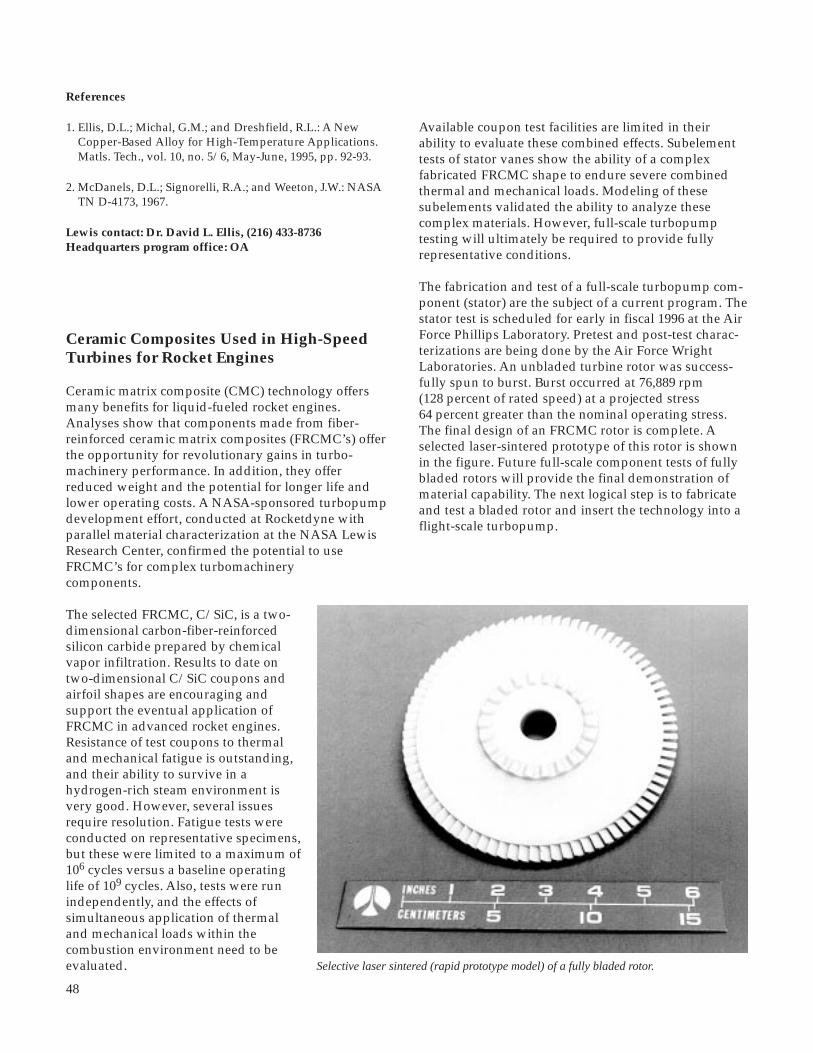
48
References
1. Ellis, D.L.; Michal, G.M.; and Dreshfield, R.L.: A New Copper-Based Alloy for High-Temperature Applications. Matls. Tech., vol. 10, no. 5/6, May-June, 1995, pp. 92-93.
2. McDanels, D.L.; Signorelli, R.A.; and Weeton, J.W.: NASA TN D-4173, 1967.
Lewis contact: Dr. David L. Ellis, (216) 433-8736Headquarters program office: OA
Ceramic Composites Used in High-SpeedTurbines for Rocket Engines
Ceramic matrix composite (CMC) technology offersmany benefits for liquid-fueled rocket engines.Analyses show that components made from fiber-reinforced ceramic matrix composites (FRCMC’s) offerthe opportunity for revolutionary gains in turbo-machinery performance. In addition, they offerreduced weight and the potential for longer life andlower operating costs. A NASA-sponsored turbopumpdevelopment effort, conducted at Rocketdyne withparallel material characterization at the NASA LewisResearch Center, confirmed the potential to useFRCMC’s for complex turbomachinerycomponents.
The selected FRCMC, C/SiC, is a two-dimensional carbon-fiber-reinforcedsilicon carbide prepared by chemicalvapor infiltration. Results to date ontwo-dimensional C/SiC coupons andairfoil shapes are encouraging andsupport the eventual application ofFRCMC in advanced rocket engines.Resistance of test coupons to thermaland mechanical fatigue is outstanding,and their ability to survive in ahydrogen-rich steam environment isvery good. However, several issuesrequire resolution. Fatigue tests wereconducted on representative specimens,but these were limited to a maximum of106 cycles versus a baseline operatinglife of 109 cycles. Also, tests were runindependently, and the effects ofsimultaneous application of thermaland mechanical loads within thecombustion environment need to beevaluated.
Available coupon test facilities are limited in theirability to evaluate these combined effects. Subelementtests of stator vanes show the ability of a complexfabricated FRCMC shape to endure severe combinedthermal and mechanical loads. Modeling of thesesubelements validated the ability to analyze thesecomplex materials. However, full-scale turbopumptesting will ultimately be required to provide fullyrepresentative conditions.
The fabrication and test of a full-scale turbopump com-ponent (stator) are the subject of a current program. Thestator test is scheduled for early in fiscal 1996 at the AirForce Phillips Laboratory. Pretest and post-test charac-terizations are being done by the Air Force WrightLaboratories. An unbladed turbine rotor was success-fully spun to burst. Burst occurred at 76,889 rpm(128 percent of rated speed) at a projected stress64 percent greater than the nominal operating stress.The final design of an FRCMC rotor is complete. Aselected laser-sintered prototype of this rotor is shownin the figure. Future full-scale component tests of fullybladed rotors will provide the final demonstration ofmaterial capability. The next logical step is to fabricateand test a bladed rotor and insert the technology into aflight-scale turbopump.
Selective laser sintered (rapid prototype model) of a fully bladed rotor.

49
Aerospace Technology
Bibliography
Brockmeyer, J.W.; and Schnittgrund, G.D.: Fiber-ReinforcedCeramic Composites for Earth-to-Orbit Rocket EngineTurbines. Final Report. NASA CR-185264, 1996.
Brockmeyer, J.W.: Ceramic Matrix Composite Applications inAdvanced Liquid Fuel Rocket Engine Turbomachinery.ASME, J. Eng. Gas Turbines Power, vol. 115, no. 1, 1993,pp. 58-63.
Eckel, A.J., et al.: Thermal Shock Fiber-Reinforced CeramicMatrix Composites. Ceram. Eng. Sci. Proc., vol. 13, no. 7-8,1991, pp. 1500-1508.
Herbell, T.P.; Eckel, A.J.; and Brockmeyer, J.W.: Compositesin High Speed Turbines for Rocket Engines. High Temper-ature High Performance Materials for Rocket Engines andAerospace Applications. TMS, 1995, pp. 13-20.
Lewis contact: Dr. Thomas P. Herbell, (216) 433-3246Headquarters program office: OA
Affordable Fiber-Reinforced CeramicComposites Win 1995 R&D 100 Award
Affordable fiber-reinforced ceramic matrix composites(AFReCC) with high strength and toughness, goodthermal conductivity, thermal shockresistance, and oxidation resistance areneeded for high-temperature structuralapplications. AFReCC materials willhave various applications in advancedhigh-efficiency and high-performanceengines: that is, the High Speed CivilTransport (HSCT), space propulsioncomponents, and land-based systems.For example, silicon-carbide-fiber-reinforced silicon carbide matrixcomposites show promise for meetingthe criteria of high strength, thermalconductivity, and toughness requiredfor the HSCT combustor liner. AFReCCreceived R&D Magazine's prestigiousR&D 100 Award in 1995.
The fabrication process for thesecomposites has three steps. In the firststep, fiber preforms are made andchemical vapor infiltration is used toapply the desired interface coating onthe fibers. This step also rigidizes thepreform. The second step consists of
resin infiltration, which after pyrolysis, yields aninterconnected network of porous carbon as the matrix.In the final step of the process, the carbon-containingpreform is infiltrated with molten silicon or siliconalloys in a furnace. This converts the carbon to siliconcarbide leaving as little as 5 percent residual free siliconor refractory disilicide phase. This process is suitablefor any type of small-diameter fiber (e.g., carbon,alumina, or silicon carbide) woven into a two-or three-dimensional architecture. This processing approachleads to dense composites where matrix microstructureand composition can be tailored for optimum proper-ties. It has much lower processing cost (<50 percent) incomparison to other approaches to fabricating silicon-carbide-based composites. The photograph shows thevarious AFReCC components. Thermomechanical andthermochemical characterization of these compositesunder the hostile environments that will be encoun-tered in engine applications is underway.
Find out more about the High Speed Civil Transport on theWorld Wide Web:http://www.lerc.nasa.gov/WWW/HSR/hsct.html
Lewis contact: Dr. Mrityunjay Singh, (216) 433-8883Headquarters program office: OA
Various AFReCC components.

50
Thermomechanical Property Data BaseDeveloped for Ceramic Fibers
A key to the successful application of metal andceramic composite materials in advanced propulsionand power systems is the judicious selection ofcontinuous-length fiber reinforcement. Appropriatefibers can provide these composites with the requiredthermomechanical performance. To aid in this selection,researchers at the NASA Lewis Research Center, usingin-house state-of-the-art test facilities, developed anextensive data base of the deformation and fractureproperties of commercial and developmental ceramicfibers at elevated temperatures. Lewis’ experimentalfocus was primarily on fiber compositions based onsilicon carbide or alumina because of their oxidationresistance, low density, and high modulus. Testapproaches typically included tensile and flexuralmeasurements on single fibers or on multifilament towfibers in controlled environments of air or argon attemperatures from 800 to 1400 ºC. Some fiber speci-mens were pretreated at composite fabricationtemperatures to simulate in situ composite conditions,whereas others were precoated with potential inter-phase and matrix materials.
For application conditions under which the fibersdisplay time-dependent mechanical behavior, testsmeasured fiber creep, rupture, and stress relaxationproperties under constant temperature and stress (orstrain) for up to ~100 hr (ref. 1). Because of the manytest variables in such studies, mechanism-basedanalytical models (ref. 2) were developed for theseproperties. Such models not only allow accurateinterpolation of time, temperature, and stress effectswithin the data set, but also permit prediction of fiberbehavior outside the data set (see figure). Thismodeling capability is particularly important for thetime variable because fiber test times are generallymuch shorter than the service lives required for someadvanced heat engine components (>104 hr).
Currently, the thermomechanical property data baseand models for a variety of ceramic fibers are publiclyavailable in numerous reports, publications, and reviewpapers (refs. 3 and 4). For component developmentalprograms outside and within NASA (EnablingPropulsion Materials (EPM) and the Advanced HighTemperature Engine Materials Technology Program(HITEMP)), these results are being used by compositedesigners and fabricators to select the optimum fiberfor each application and also by the fiber manufactur-ers to understand and improve fiber performance.Research at Lewis is continuing in order to expand the
data base and improve the property models, particu-larly for those fiber types with the most technicalpotential.
References
1. DiCarlo, J.A.: Property Goals and Test Methods for High Temperature Ceramic Fiber Reinforcement. Adv. Sci. Tech. 1995, vol. 7, 1995.
2. DiCarlo, J.A., et al.: Models for the Thermostructural Properties of SiC Fibers. High Temperature Ceramic-Matrix Composites I, A.G. Evans and R. Naslain, eds. Ceramic Trans., vol. 57, American Ceramic Society, 1995, pp. 343-348.
3. Tressler, R.E.; and DiCarlo, J.A.: Creep and Rupture of Advanced Ceramic Reinforcements. High Temperature Ceramic-Matrix Composites II, A.G. Evans and R. Naslain, eds. Ceramic Transactions, vol. 57, American Ceramic Society, 1995, pp. 141-155.
4. DiCarlo, J.A.; and Dutta, S: Continuous Ceramic Fibers for Ceramic Composites. Handbook on Continuous Fiber- Reinforced Ceramic Matrix Composites, chapter 4, R.L. Lehman, S.K. El-Rahaiby, and J.B. Wachtman, eds. Ceramics Information Analysis Center, Purdue University (West Lafayette, IN), 1995.
Lewis contact: Dr. James A. DiCarlo, (216) 433-5514Headquarters program office: OA
800 1400Temperature, °C
Fib
er s
tren
gth
, MP
a
01600
1000
12001000
200
600
400
800
1200
Rupture strengthCreep strength (1-percent creep)
1400
10 000 hr 100 hr
Creep and rupture strengths of Hi-Nicalon silicon carbide fibers forservice lives of 102 and 104 hr. Symbols indicate actual data pointsand lines indicate predictions from property models.
,

51
Aerospace Technology
Silicon Carbide Epitaxial Films Studied byAtomic Force Microscopy
Silicon carbide (SiC) holdsgreat potential as an elec-tronic material because of itswide band gap energy, highbreakdown electric field,thermal stability, andresistance to radiationdamage. Possible aerospaceapplications of high-temperature, high-power, orhigh-radiation SiC electronicdevices include sensors,control electronics, andpower electronics that canoperate at temperatures upto 600° C and beyond.Commercially available SiCdevices now include bluelight-emitting diodes (LED’s)and high-voltage diodes foroperation up to 350 °C, withother devices under devel-opment (ref. 1). At present,morphological defects in epitaxially grown SiC filmslimit their use in device applications. Research gearedtoward reducing the number of structural inhomo-geneities can benefit from an understanding of the typeand nature of problems that cause defects. The AtomicForce Microscope (AFM) has proven to be a useful toolin characterizing defects present on the surface of SiCepitaxial films.
The in-house High-Temperature Integrated Electronicsand Sensors (HTIES) Program at the NASA LewisResearch Center not only extended the dopant con-centration range achievable in epitaxial SiC films, butit reduced the concentration of some types of defects(ref. 2). Advanced structural characterization using theAFM was warranted to identify the type and structureof the remaining film defects and morphologicalinhomogeneities. The AFM can give quantitativeinformation on surface topography down to molecularscales. Acquired, in part, in support of the AdvancedHigh Temperature Engine Materials TechnologyProgram (HITEMP), the AFM had been used previouslyto detect partial fiber debonding in composite materialcross sections (ref. 3).
Atomic force microscopy examination of epitaxial SiCfilm surfaces revealed molecular-scale details of someunwanted surface features. Growth pits propagatingfrom defects in the substrate, and hillocks due,
presumably, to existing screw dislocations in thesubstrates, were imaged. Away from local defects, stepbunching was observed to yield step heights of hun-dreds of angstroms, with possible implications for theuniformity of dopants incorporated in SiC devicesduring fabrication. The quantitative topographic datafrom the AFM allow the relevant defect information tobe extracted, such as the size and distribution of stepbunching and the Burgers vector of screw dislocations(ref. 4).
These atomic force microscopy results have furtheredthe understanding of the dynamic epitaxial SiC growthprocess. A model describing the observed hillock stepbunching has been proposed. This cooperation betweenresearchers involved in crystal growth, electronic dev-ice fabrication, and surface structural characterization islikely to continue as atomic force microscopy is used toimprove SiC films for high-temperature electronicdevices for NASA’s advanced turbine engines andspace power devices, as well as for future applicationsin the automotive industry.
References
1. Powell, J.A., et al.: Progress in Silicon Carbide Semicon- ductor Technology, Mater. Resr. Soc. Symp. Proc. vol. 242, 1992, pp. 495-505.
Å300150
0
3
2
1
00 1 2 3
mm
mm
Atomic force microscopy image of spiral steps propagating from the peak of a 6H-SiC hillock. Steps,which are produced by a super screw dislocation, evidence anisotropic step-bunching.
µm

52
2. Neudeck, P.G., et al.: Greatly Improved 3C-SiC p-n Junction Diodes Grown by Chemical Vapor Deposition, IEEE Electron. Device. Lett., vol. 14, no. 3, 1993, pp. 136-139.
3. Eldridge, J.I.; Abel, P.B.; and Ghosn, L.J.: The Effect of Fiber/Matrix Thermal Expansion Mismatch on Fiber Debond Initiation During Fiber Push-Out. HITEMP Review 1994, NASA CP-10146, Vol. III, 1994, pp. 82-1 to 82-11. (Available to U.S. citizens only. Permission to use this material was granted by Hugh R. Gray, January 1996.)
4. Powell, J.A., et al.: Effect of Tilt Angle on the Morphology of SiC Epitaxial Films Grown on Vicinal (0001) SiC Substrates. Accepted for publication in the Proceedings of the 6th International Conference on Silicon Carbide and Related Materials—1995, Kyoto, Japan, Sept. 18-22, 1995.
Find out more about the AFM on the World Wide Web:http://www.lerc.nasa.gov/WWW/SurfSci/ssb_siac.html
Lewis contacts: Phillip B. Abel, (216) 433-6063, andJ. Anthony Powell, (216) 433-3652Headquarters program office: OA
Self-Lubricating, Wear-Resistant DiamondFilms Developed for Use in VacuumEnvironment
Diamond’s outstanding properties—extreme hardness,chemical and thermal inertness, and high strength andrigidity—make it an ideal material for many tribo-logical applications, such as the bearings, valves,and engine parts in the harsh environment found ininternal-combustion engines, jet engines, and spacepropulsion systems.
It has been demonstrated that chemical-vapor-deposited diamond films have low coefficients offriction (on the order of 0.01) and low wear rates (<10-7
mm3/N-m) both in humid air and dry nitrogen but thatthey have both high coefficients of friction (>0.4) andhigh wear rates (on the order of 10-4 mm3/N-m) invacuum. It is clear that surface modifications thatprovide acceptable levels of friction and wear proper-ties will be necessary before diamond films can be usedfor tribological applications in a spacelike, vacuumenvironment. Previously, it was found that coatings ofamorphous, nondiamond carbon can provide lowfriction in vacuum. Therefore, to reduce the friction andwear of diamond film in vacuum, carbon ions were
implanted in an attempt to form a surface layer ofamorphous carbon phases on the diamond films.
Diamond films with grain sizes ranging from 20 to3300 nm were deposited on silicon, silicon carbide, andsilicon nitride by microwave-plasma-assisted chemicalvapor deposition. Carbon ions were implanted into theas-deposited diamond films at an accelerating energy of60 keV and a current density of 50 µA/cm2 for approx-imately 6 min, resulting in a dose of 1.2x10¹⁷ carbonions/cm2. The substrate temperatures during ionimplantation did not exceed 200 °C. The as-depositedand ion-implanted diamond films were characterized atthe NASA Lewis Research Center through the use of avariety of techniques—such as scanning and trans-mission electron microscopy, surface profilometry, andRaman spectroscopy. The friction and wear propertiesof these films in contact with a natural bulk diamondpin at a mean hertzian contact pressure of 2 GPa wereexamined in an ultrahigh vacuum of 7x10⁻⁷ Pa at roomtemperature.
The results indicate that carbon ion implantationstructurally modified the diamond lattice and produceda thin surface layer of amorphous, nondiamond carbon(as verified by the Raman data in the figure). Theamorphous, nondiamond carbon greatly decreasedboth the friction and wear of the diamond films. Thecoefficients of friction for the carbon-ion-implanted,fine-grain diamond films were less than 0.1, factors of20 to 30 lower than those for the as-deposited, fine-grain diamond films. The coefficients of friction for thecarbon-ion-implanted, coarse-grain diamond filmswere approximately 0.35, a factor of 5 lower than thosefor the as-deposited, coarse-grain diamond films. Thewear rates for the carbon-ion-implanted diamond filmswere on the order of 10-6 mm3/N·m, factors of 30 to 80lower than those for the as-deposited diamond films,regardless of grain size.
The friction of the carbon-ion-implanted diamondfilms was greatly reduced because the amorphous,nondiamond carbon, which exhibited a low shearstrength, was restricted to the surface layers (<0.1-µmthick) and because the underlying diamond materialsretained their high hardness. The size andmorphological characteristics of the wear debrisparticles were related to the wear rates. Much finerwear particles were generated on the surfaces of thecarbon-ion-implanted diamond films than weregenerated on the surfaces of the as-deposited diamondfilms. Thus, the carbon-ion-implanted, fine-graindiamond films can be used effectively as wear-resistant,self-lubricating coatings for ceramics, such as siliconnitride and silicon carbide, in ultrahigh vacuum.

53
Wavenumber, cm–1
600 800 1000 1200 1400 1600 1800 20000
2000
4000
6000
8000
As deposited
Arb
itrar
y in
tens
ity
Raman spectra of as-deposited and carbon-ion-planted, coarse-grain diamond film on an α-SiC substrate. Spectra are vertically displaced forviewing purposes.
Aerospace Technology
Carbon-ion implanted
Bibliography
Miyoshi, K., et al.: Physical and Tribological Characteristics ofIon-Implanted Diamond Films, NASA TM-106682, Nov. 1994.
Lewis contacts: Dr. Kazuhisa Miyoshi, (216) 433-6078, andDr. Susan L. Heidger, (216) 433-6057Headquarters program office: OA

54
Lubricous Deposit Formed In Situ BetweenWearing Surfaces at High Temperatures
Many components of future aircraft will be constructedfrom novel high-temperature materials, such as super-alloys and ceramic composites, to meet expected opera-ting temperatures in excess of 300 °C. There are noknown liquid lubricants that can lubricate above 300 °Cwithout significant decomposition. Solid lubricantscould be considered, but problems caused by the higherfriction coefficients and wear rates of the solid lubricantfilm make this an undesirable approach. An alternativemethod of lubrication is currently being investigated:vapor phase lubrication.
In vapor phase lubrication, an organic liquid (in ourstudies a thioether was used) is vaporized into aflowing air stream that is directed to sliding surfaceswhere lubrication is needed. The organic vapor reacts atthe concentrated contact sliding area generating alubricous deposit. This deposit has been characterizedas a thin polymeric film that can provide effectivelubrication at temperatures greater than 400 °C.
Initial tribological studies were conducted at the NASALewis Research Center and Cleveland State Universitywith a high-temperature friction and wear tribometer.A cast iron rod was loaded (a 4-kg mass was usedto generate a contact pressure of 1.2 MPa) against areciprocating, cast iron plate at 500 °C. This system
was then lubricated with the vapor phase of thioether.The following results were obtained:
• The deposited film resulted in friction coefficients as low as 0.01.• Cast iron wear was not detectable.• The system could self-recover: when the vapor flow was stopped and the system allowed to go into failure (a friction coefficient greater than 0.3), renewal of the vapor flow reduced the friction coefficient back to 0.01.• The amount of thioether used was 0.014 wt % in air (1.2 ml/hr of lubricant in 2000 ml/min air).
These results were so promising that Cleveland StateUniversity filed a patent application listing Dr. EarlGraham (Cleveland State University) and Dr. WilfredoMorales (NASA Lewis Research Center) as coinventors.
Vapor phase lubrication will not only allow operationat higher temperatures, but it will produce a net sav-ings in weight aboard aircraft because no large oilreservoirs will be needed.
Lewis contact: Dr. Wilfredo Morales, (216) 433-6052Headquarters program office: OA
0 75 125Time, min
Co
effic
ient
of
fric
tion
0100
0.25
5025
0.05
0.15
0.10
0.20
0.30
150 175 200
Initialconcentration,1.6 ml/hr
Changedto 0.81 ml/hr
at 182 m
Changedto 0.57 ml/hr
at 400 m
Changedto 0.32 ml/hr
at 490 m
Changedto 0.25 ml/hr
at 680 m
Changedto 0.16 ml/hr
at 1120 m
0.014 wt %
Coefficient of friction versus time for various concentrations of thioether in air. Thioether on cast iron; plate temperature,500 ºC; vapor temperature, 400 ºC; load, 4 kg.

55
DMBZ Polyimides Provide an Alternative toPMR-15 for High-Temperature Applications
PMR-15, a high-temperature polyimide developed inthe mid-1970’s at the NASA Lewis Research Center,offers the combination of ease of processing, low cost,and good stability and performance at temperatures upto 288 °C (500 °F). This material is widely regarded asone of the leading high-temperature matrix resins forpolymer-matrix-composite aircraft engine components.PMR-15 is widely used in both military and civilianaircraft engines. The current worldwide market forPMR-15 is on the order of 50,000 lb, with a total sales ofaround $5 to $10 million.
However, PMR-15 is made from methylene dianiline(MDA), a known animal mutagen and a suspectedhuman mutagen. Recent concerns about the safety ofworkers involved in the manufacture and repair ofPMR-15 components have led to the implementation ofcostly protective measures to limit worker exposureand ensure workplace safety. In some cases, because ofsafety and economic concerns, airlines have eliminatedPMR-15 components from engines in their fleets.
Current efforts at Lewis are focused on developingsuitable replacements for PMR-15 that do not containmutagenic constituents and have processability,stability, and mechanical properties comparable to thatof PMR-15. A recent development from these efforts isa new class of thermosetting polyimides based on 2,2’-dimethylbenzidine (DMBZ). Autoclave processingdeveloped for PMR-15 composites was used to preparelow-void-content T650-35 carbon-fiber-reinforcedlaminates from DMBZ-15 polyimides. The glass transi-tion temperatures of these laminates were about 50 °Chigher than those of the T650-35/PMR-15 composites(400 versus 348 °C). In addition, DMBZ-15 polyimidecomposites aged for 1000 hr in air at 288 °C (500 °F)had weight losses close to those of comparable PMR-15laminates (0.9 versus 0.7 percent). The elevated (288 °C)and room-temperature mechanical properties of T650-35-reinforced DMBZ-15 polyimide and PMR-15laminates were comparable (see figure). Standard Amestests are being conducted on this diamine to assess itsmutagenicity.
Lewis contact: Dr. Kathy C. Chuang, (216) 433-3227Headquarters program office: OA
Elevated and room-temperature mechanical properties of DMBZ and PMR-15 composites. Left: Interlaminate strength. Center:Flexural modulus. Right: Flexural strength.
Aerospace Technology
18
16
14
12
10
8
6
4
2
0
PMR-15DMBZ-15
ILL
shea
r str
eng
th, k
si
Flex
ural
mod
ulus
, msi
25
20
15
10
5
0
Fle
xura
l str
eng
th, k
si
300
250
200
150
100
50
0Room
temperature550 ºF
(288 ºC)Room
temperature550 ºF
(288 ºC)Room
temperature550 ºF
(288 ºC)Room
temperature550 ºF
(288 ºC)

56
Low-Cost Resin Transfer Molding ProcessDeveloped for High-Temperature PolyimideMatrix Composites
The use of high-temperature polymer matrix composi-tes (PMC’s) in aircraft engine applications can signifi-cantly reduce engine weight and improve performanceand fuel efficiency. High-temperature PMC’s, such asthose based on the PMR-15 polyimide matrix resindeveloped by the NASA Lewis Research Center, havebeen used extensively in military applications whereperformance improvements have justified their useregardless of the cost involved in producing the compo-nent. However, in commercial engines cost is a primarydriver, and PMC components must be produced atcosts comparable to those of the metal components thatthey will replace.
Current production methods used to manufacturecomponents from high-temperature PMC’s are fairlylabor intensive. Although less labor intensive, moreefficient processing techniques such as resin transfermolding (RTM) have been developed to process PMC’s;these methods are not suitable for use with high-temperature PMC’s. RTM involves infiltrating a fiberpreform with molten resin. To process good qualityparts via RTM, one must use a resin with a low enoughviscosity and sufficiently long pot-life to completelyinfiltrate the preform. Although high-temperaturepolymers such as PMR-15 melt, the viscosity of themolten resin is too high to be successfully processed byRTM.
One of the goals of the Advanced Subsonic Technologyprogram is to develop new processing methods thatenable the low-cost production of high-temperaturePMC engine hardware. A recent development of thisprogram is a modification of the RTM process to allowcomplete infiltration of the fiber preform by monomersprior to processing. A demonstration of this technique,developed jointly by GE Aircraft Engines, FiberInnovations, Inc., and Lewis, was successfully com-pleted, leading to the production of a center vent tubefor the GE-90 engine using a Lewis-developed high-temperature polyimide, AMB-21. It is estimated thatthis process could reduce manufacturing costs by 30 to50 percent in comparison to costs for a comparable partproduced by hand layup and autoclave processing.Furthermore, this technique should be applicable to avariety of high-temperature PMC’s as well as to a
number of engine components. Engine testing of thisRTM-processed center vent tube is currently underway.
Find out more about the Advanced Subsonic Technologyprogram on the World Wide Web:http://bearcat.lerc.nasa.gov/ast.html
Lewis contact: Raymond D. Vannucci, (216) 433-3202Headquarters program office: OA
Resin transfer molded AMB-21 Center Vent Tube forthe GE-90 engine.

57
Nuclear Magnetic Resonance Used toQuantify the Effect of Pyrolysis Conditionson the Oxidative Stability of SiliconOxycarbide Ceramics
This work was undertaken in support of the Low CostCeramic Composite Virtual Company, (LC3), whosemembers include Northrop Grumman Corporation,AlliedSignal Inc., and Allison Advanced DevelopmentCompany. LC3 is a cost-shared effort funded by theAdvanced Research Projects Agency (ARPA) and theLC3 participants to develop a low-cost fabricationmethodology for manufacturing ceramic matrix com-posite structural components. The program, which isbeing administered by the U.S. Air Force WrightLaboratory Materials Directorate, is focused on demon-strating a ceramic matrix composite turbine seal for aregional aircraft engine. This part is to be fabricated byresin transfer molding of a siloxane polymer into a fiberpreform that will be transformed into a ceramic bypyrolytic conversion.
Pyrolysis conditions are known to have a profoundeffect on the silicon redistribution reactions involved inconverting the polymer into a ceramic (refs. 1 and 2).Different relative amounts of silicon carbide, siliconoxide, and silicon oxycarbides are produced, dependingon the structure of the starting polymer and the pyroly-sis path. These variations directly affect the oxidativestability. The purpose of this study was to quantify theeffect of pyrolysis variables, namely time and tem-perature, on the redistribution reactions and, hence, onthe oxidative stability.
Solid sample 29Si nuclear magnetic resonancespectroscopy (NMR) can distinguish between varioussilicon species. For that reason, 29Si NMR was used inthis study to directly measure the percent peak areasof silicon carbide, silicon oxide, and siliconoxycarbides in ceramic test samples. Samples wereproduced under different pyrolysis conditions andwere analyzed both before and after oxidation for500 hr at 600 ºC. The pyrolysis temperature wasvaried between 900 and 1100 ºC, and the pyrolysistime was varied from 1 to 5 hr.
Ceramic samples were prepared by AlliedSignaland analyzed by NMR at the NASA Lewis ResearchCenter. The experiments were carried out under astatistical design in a randomized run order. In thisway, the data could be analyzed by multiple linearleast squares regression to give models predictingthe effect of the variables on the NMR peak areas. Athree-dimensional graph of the predictive model forpercent silicon carbide peak plotted versus pyrolysis
temperature and oxidation time is shown. The shadedbands represent silicon carbide contours in 5-percentintervals. This graph clearly demonstrates that in-creasing pyrolysis temperature significantly increasesthe amount of silicon carbide produced duringpyrolysis. This increased silicon carbide productiongreatly improved oxidative stability, as evidenced bythe greater retention of silicon carbide after oxidation.Pyrolysis time had little effect on percent siliconcarbide.
We concluded that pyrolysis at 1100 ºC produces themost oxidatively stable ceramic matrix. Furthermore,for samples like these with large surface-to-volumeratios, there is no benefit in pyrolyzing for more than1 hr. Shorter pyrolysis cycles can greatly reduce thecost of producing the ceramic part.
References
1. Hurwitz, F.I., et al.: Characterization of the Pyrolytic Conversion of Polysilsesquioxanes to Silicon Oxycarbides. J. Mater. Sci., vol. 28, 1993, pp. 6622-6630.
2. Hurwitz, F.I.; Heimann, P.J.; and Kacik, T.A.: Redistribution Reactions in BlackglasTM During Pyrolysis and Their Effect on Oxidative Stability. Ceram. Eng. and Sci. Proc., vol. 16, no. 4, 1995, pp. 217-224.
Lewis contacts: Dr. Mary Ann Meador, (216) 433-3221, andDr. Frances I. Hurwitz, (216) 433-5503Headquarters program office: OA
Aerospace Technology
Predictive model for percent silicon carbide peak area plottedversus pyrolysis temperature and oxidation time.
Content,percent
Oxidationtime, hr
Pyrolysistemperature,
°C
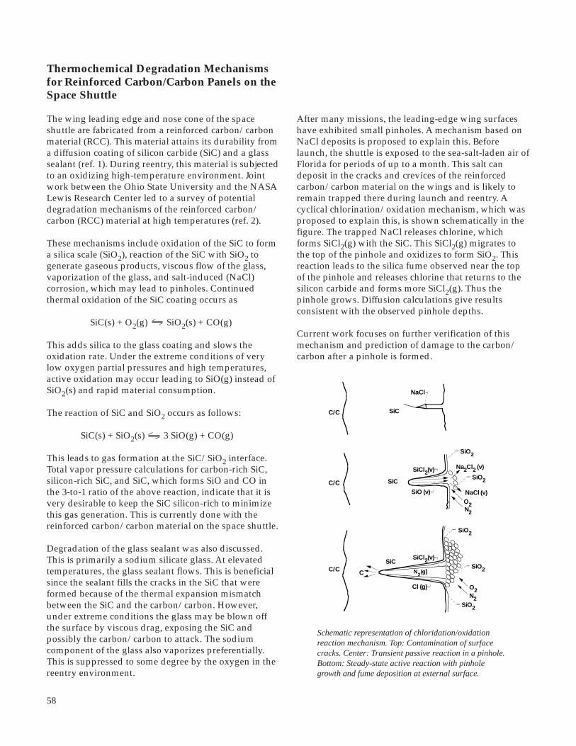
58
Thermochemical Degradation Mechanismsfor Reinforced Carbon/Carbon Panels on theSpace Shuttle
The wing leading edge and nose cone of the spaceshuttle are fabricated from a reinforced carbon/carbonmaterial (RCC). This material attains its durability froma diffusion coating of silicon carbide (SiC) and a glasssealant (ref. 1). During reentry, this material is subjectedto an oxidizing high-temperature environment. Jointwork between the Ohio State University and the NASALewis Research Center led to a survey of potentialdegradation mechanisms of the reinforced carbon/carbon (RCC) material at high temperatures (ref. 2).
These mechanisms include oxidation of the SiC to forma silica scale (SiO2), reaction of the SiC with SiO2 togenerate gaseous products, viscous flow of the glass,vaporization of the glass, and salt-induced (NaCl)corrosion, which may lead to pinholes. Continuedthermal oxidation of the SiC coating occurs as
SiC(s) + O2(g) SiO2(s) + CO(g)
This adds silica to the glass coating and slows theoxidation rate. Under the extreme conditions of verylow oxygen partial pressures and high temperatures,active oxidation may occur leading to SiO(g) instead ofSiO2(s) and rapid material consumption.
The reaction of SiC and SiO2 occurs as follows:
SiC(s) + SiO2(s) 3 SiO(g) + CO(g)
This leads to gas formation at the SiC/SiO2 interface.Total vapor pressure calculations for carbon-rich SiC,silicon-rich SiC, and SiC, which forms SiO and CO inthe 3-to-1 ratio of the above reaction, indicate that it isvery desirable to keep the SiC silicon-rich to minimizethis gas generation. This is currently done with thereinforced carbon/carbon material on the space shuttle.
Degradation of the glass sealant was also discussed.This is primarily a sodium silicate glass. At elevatedtemperatures, the glass sealant flows. This is beneficialsince the sealant fills the cracks in the SiC that wereformed because of the thermal expansion mismatchbetween the SiC and the carbon/carbon. However,under extreme conditions the glass may be blown offthe surface by viscous drag, exposing the SiC andpossibly the carbon/carbon to attack. The sodiumcomponent of the glass also vaporizes preferentially.This is suppressed to some degree by the oxygen in thereentry environment.
After many missions, the leading-edge wing surfaceshave exhibited small pinholes. A mechanism based onNaCl deposits is proposed to explain this. Beforelaunch, the shuttle is exposed to the sea-salt-laden air ofFlorida for periods of up to a month. This salt candeposit in the cracks and crevices of the reinforcedcarbon/carbon material on the wings and is likely toremain trapped there during launch and reentry. Acyclical chlorination/oxidation mechanism, which wasproposed to explain this, is shown schematically in thefigure. The trapped NaCl releases chlorine, whichforms SiCl2(g) with the SiC. This SiCl2(g) migrates tothe top of the pinhole and oxidizes to form SiO2. Thisreaction leads to the silica fume observed near the topof the pinhole and releases chlorine that returns to thesilicon carbide and forms more SiCl2(g). Thus thepinhole grows. Diffusion calculations give resultsconsistent with the observed pinhole depths.
Current work focuses on further verification of thismechanism and prediction of damage to the carbon/carbon after a pinhole is formed.
SiC
NaCl
C/C
O2N2
SiO2
NaCl (v)
Na2Cl2 (v)
SiO2
SiCl2(v)
SiO (v)
SiCC/C
SiC
N2(g)SiO2
O2N2
SiO2
SiO2
SiCl2(v)
Cl (g)
CC/C
Schematic representation of chloridation/oxidationreaction mechanism. Top: Contamination of surfacecracks. Center: Transient passive reaction in a pinhole.Bottom: Steady-state active reaction with pinholegrowth and fume deposition at external surface.

59
References
1. Williams, S.D., et al.: Ablation Analysis of the Shuttle Orbiter Oxidation Protected Reinforced Carbon-Carbon. AIAA Paper 94-2084, 1994.
2. Jacobson, N.S.; and Rapp, R.A.: Thermochemical Degradation Mechanisms for the Reinforced Carbon/ Carbon Panels on the Space Shuttle. NASA TM-106793, 1995.
Lewis contact: Dr. Nathan S. Jacobson, (216) 433-5498Ohio State University contact: Prof. Robert A. Rapp,(614) 292-6178Headquarters program office: OA
Cascade Optimization Strategy MaximizesThrust for High-Speed Civil TransportPropulsion System Concept
The design of a High-Speed Civil Transport (HSCT) air-breathing propulsion system for multimission, variable-cycle operations was successfully optimized through asoft coupling of the engine performance analyzerNASA Engine Performance Program (NEPP) to amultidisciplinary optimization tool COMETBOARDSthat was developed at the NASA Lewis ResearchCenter. The designoptimization of this enginewas cast as a nonlinearoptimization problem, withengine thrust as the meritfunction and the bypassratios, r-values of fans, fuelflow, and other factors asimportant active designvariables. Constraints werespecified on factors includingthe maximum speed of thecompressors, the positivesurge margins for the com-pressors with specified safetyfactors, the discharge tem-perature, the pressure ratios,and the mixer extreme Machnumber.
Solving the problem by usingthe most reliable optimizationalgorithm available inCOMETBOARDS would
provide feasible optimum results only for a portion ofthe aircraft flight regime because of the large numberof mission points (defined by altitudes, Mach numbers,flow rates, and other factors), diverse constraint types,and overall poor conditioning of the design space. Onlythe cascade optimization strategy of COMETBOARDS,which was devised especially for difficult multidisci-plinary applications, could successfully solve a numberof engine design problems for their flight regimes.Furthermore, the cascade strategy converged to thesame global optimum solution even when it wasinitiated from different design points. Multipleoptimizers in a specified sequence, pseudorandomdamping, and reduction of the design space distortionvia a global scaling scheme are some of the key featuresof the cascade strategy.
The figure depicts a COMETBOARDS solution for anHSCT engine (Mach-2.4 mixed-flow turbofan) alongwith its configuration. The optimum thrust is normal-ized with respect to NEPP results. COMETBOARDSadded value in the design optimization of the HSCTengine.
Find out more about the HSCT on the World Wide Web:http://www.lerc.nasa.gov/WWW/HSR/hsct.html
Lewis contact: Dale A. Hopkins, (216) 433-3260Headquarters program office: OA
0 75 125Mission points
No
rmal
ized
op
timum
thr
ust
1005025
1.00
1.05
1.10
COMETBOARDS solutionNEPP solution
High-pressure turbine
High-pressure compressor Burner
Low-pressure turbine
Inlet
Bypass duct
FanNozzle
122
0.95
HSCT engine concept, optimized solution for HSCT engine concept.
Aerospace Technology
Structures

60
Impact Properties of Metal Fan ContainmentMaterials Being Evaluated for theHigh-Speed Civil Transport (HSCT)
Under the Enabling Propulsion Materials (EPM)program—a partnership between NASA, Pratt &Whitney, and GE Aircraft Engines—the Materials andStructures Divisions of the NASA Lewis ResearchCenter are involved in developing a fan-containmentsystem for the High-Speed Civil Transport (HSCT). Theprogram calls for a baseline system to be designed bythe end of 1995, with subsequent testing of innovativeconcepts. Five metal candidate materials are cur-rently being evaluated for the baseline system in theStructures Division’s Ballistic Impact Facility.
This facility was developed to provide the EPM pro-gram with cost-efficient and timely impact test data.At the facility, material specimens are impacted atspeeds up to 350 m/sec by projectiles of various sizesand shapes to assess the specimens’ ability to absorbenergy and withstand impact. The tests can beconducted at either room or elevated temperatures.Posttest metallographic analysis is conducted toimprove understanding of the failure modes. Adynamic finite element program is used to simulatethe events and both guide the testing as well as aid indesigning the fan-containment system.
To date, four of the five candidates for the baselinesystem have been tested. We plan to test the fifthmaterial at Lewis as soon as it is available. Tests onmore innovative materials and designs are currently
Active Piezoelectric Structures for TipClearance Management Assessed
Managing blade tip clearance in turbomachinery stagesis critical to developing advanced subsonic propulsionsystems. Active casing structures with embeddedpiezoelectric actuators appear to be a promising solu-tion. They can control static and dynamic tip clearance,compensate for uneven deflections, and accomplishelectromechanical coupling at the material level. Inaddition, they have a compact design. To assess thefeasibility of this concept and assist the developmentof these novel structures, the NASA Lewis ResearchCenter developed in-house computational capabilitiesfor composite structures with piezoelectric actuatorsand sensors, and subsequently used them to simulatecandidate active casing structures.
The simulations indicated the potential of active casingsto modify the blade tip clearance enough to improvestage efficiency. They also provided valuable designinformation, such as preliminary actuator configu-rations (number and location) and the correspondingvoltage patterns required to compensate for unevencasing deformations. The figure illustrates an activeovalization of a casing with four discrete piezoceramicactuators attached on the outer surface. The centerfigure shows the predicted radial displacements alongthe hoop direction that are induced when electrostaticvoltage (bottom figure) is applied at the piezoceramicactuators. This work, which has demonstrated thecapabilities of in-house computational models toanalyze and design active casing structures, is expectedto contribute toward the development of advancedsubsonic engines.
Velocity required for a standard projectile to penetrate fourcandidate materials at 370 ºC (700 ºF).
being initiated. Results of these tests will be used toselect materials for further large-scale testing, andto help engine designers in the design of the fan-containment system.
Find out more about the HSCT on the World Wide Web:http://www.lerc.nasa.gov/WWW/HSR/hsct.html
Lewis contact: J. Michael Pereira, (216) 433-6738Headquarters program office: OA (HSRD)
800
700
600
500
400
Vel
oci
ty, f
t/se
c
1 2 3 4
Areal weight, lb/ft2
1234
Material

61
Microalloying Improves the Low-CycleFatigue Behavior of Powder-Extruded NiAl
There is considerable interest in developing newstructural materials in which high use temperaturesand strength, coupled with low density, are the mini-mum requirements. The goal for these new materials isto provide operation well beyond the working range ofconventional superalloys. Of the many intermetallicsunder consideration, NiAl is one of the few systemsthat has emerged as a promising candidate for furtherdevelopment. This is because of a number of propertyadvantages—including low density, high meltingtemperature, high thermal conductivity, and excellentenvironmental resistance. However, binary NiAl lacksstrength and creep resistance at elevated temperatures.Also, its poor high-temperature strength results inworse-than-predicted low-cycle fatigue (LCF) livesat low strain ranges at 727 °C (1341 °F) because ofaccelerated creep damage mechanisms that result insignificant intergranular cracking (refs. 1 and 2). Oneapproach for improving these properties involvesmicroalloying NiAl with either Zr or N. As an integralpart of this alloy-development program at the NASALewis Research Center, the low-cycle fatigue behaviorof Zr- and N-doped nickel aluminides produced byextrusion of prealloyed powders was investigatedand compared with similarly processed binary NiAl.
The fatigue-life behavior of the various NiAl alloys isplotted in the first figure. Two stages occurred in thetotal strain-life plot of NiAl(Zr) because the fracturebehavior changed from slow and stable intergranularcrack growth at strain ranges ≤0.38 percent to brittle-cleavage-dominated overload fracture above this value.At strain ranges above 0.38 percent, the peak tensilestress reached the monotonic cleavage fracture stressof the Zr-doped alloy at 1000 K (328 MPa) in less than100 cycles, enabling fast crack growth by cleavage. Attotal strain ranges ≤0.38 percent, the peak tensile cyclicstresses remained at a much lower level than the tensilecleavage fracture stress. In general, fatigue lives aregoverned by the ductility of the material at high strainsand by its strength at low strains. The longer lives ofNiAl(Zr) at low strain ranges result from its basiccapacity to resist the applied strains on the basis ofhigh strength. Both the NiAl and NiAl(N) alloyshave shorter lives at low strain ranges because of thesynergistic interaction between fatigue and creep. Forthe fatigue resistance of the binary and N-doped alloyto be improved, the grain boundaries need to bestrengthened by a suitable means to reduce grain-boundary sliding and associated intergranular wedgecracking. Because Zr segregates to the grain bound-aries in NiAl (ref. 3) and apparently strengthens the
Aerospace Technology
Active ring structures with piezoelectric actuators. Top:Typical configuration. Center: Induced radial deflections.Bottom: Applied electric voltage at actuators.
Bibliography
Heyliger, P.; Ramirez, G.; and Saravanos, D.: CoupledDiscrete-Layer Finite Elements for Laminated PiezoelectricPlates. Commun. Numer. Meth. Eng., vol. 10, 1994, pp.971-981.
Saravanos, D.A., et al.: On Smart Composite Structures forActive Tip Clearance Control. Adaptive Structures andComposite Materials Analysis and Application. E. Garcia,H. Cudney, and A. Dasgupta, eds., ASME, New York, 1994.
Lewis contact: Dale A. Hopkins (216) 433-3260Headquarters program office: OA
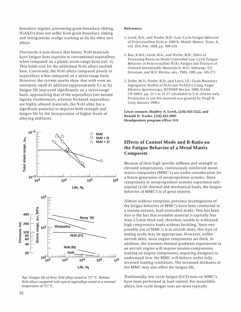
62
103 104 105 106
NiAlNiAl + NNiAl + Zr
10–3
10–2
To
tal s
trai
n ra
nge,
De t
Life, Nf
102 103 104 105 106102
103
Str
ess
rang
e, D
s, M
Pa
Life, Nf
104
Pre
ssur
e, k
si
Rene '95
Waspaloy
NiAl (Zr)
NiAl (N)
NiAl
400
100
20
200
60
40
80
boundary regions, preventing grain-boundary sliding,NiAl(Zr) does not suffer from grain-boundary slidingand intergranular wedge cracking as do the other twoalloys.
Previously it was shown that binary NiAl materialshave fatigue lives superior to conventional superalloyswhen compared on a plastic strain-range basis (ref. 1).This holds true for the additional NiAl alloys studiedhere. Conversely, the NiAl alloys compared poorly tosuperalloys when compared on a stress-range basis.However, the current results show that with even anextremely small Zr addition (approximately 0.1 at.%)fatigue life improved significantly on a stress-rangebasis, approaching that of the superalloys (see secondfigure). Furthermore, whereas Ni-based superalloysare highly alloyed materials, the NiAl alloy has asignificant potential to improve both strength andfatigue life by the incorporation of higher levels ofalloying additions.
References
1. Lerch, B.A.; and Noebe, R.D.: Low-Cycle Fatigue Behavior of Polycrystalline NiAl at 1000 K. Metall. Maters. Trans. A, vol. 25A, Feb. 1994, pp. 309-319.
2. Rao, K.B.S.; Lerch, B.A.; and Noebe, R.D.: Effect of Processing Route on Strain Controlled Low Cycle Fatigue Behavior of Polycrystalline NiAl. Fatigue and Fracture of Ordered Intermetallic Materials II, W.O. Soboyejo, T.S. Srivatsan, and R.O. Ritchie, eds., TMS, 1995, pp. 245-271.
3. Zeller, M.V.; Noebe, R.D.; and Locci, I.E.: Grain Boundary Segregation Studies of NiAl and NiAl(Zr) Using Auger Electron Spectroscopy. HITEMP Review 1990, NASA CP-10051, pp. 21-1 to 21-17. (Available to U.S. citizens only. Permission to use this material was granted by Hugh R. Gray, January 1996.)
Lewis contacts: Bradley A. Lerch, (216) 433-5522, andRonald D. Noebe, (216) 433-2093Headquarters program office: OA
Top: Fatigue life of three NiAl alloys tested at 727 ºC. Bottom:NiAl alloys compared with typical superalloys tested at a nominaltemperature of 727 ºC.
Effects of Control Mode and R-Ratio onthe Fatigue Behavior of a Metal MatrixComposite
Because of their high specific stiffness and strength atelevated temperatures, continuously reinforced metalmatrix composites (MMC’s) are under consideration fora future generation of aeropropulsion systems. Sincecomponents in aeropropulsion systems experience sub-stantial cyclic thermal and mechanical loads, the fatiguebehavior of MMC’s is of great interest.
Almost without exception, previous investigations ofthe fatigue behavior of MMC’s have been conducted ina tension-tension, load-controlled mode. This has beendue to the fact that available material is typically lessthan 2.5-mm thick and, therefore, unable to withstandhigh compressive loads without buckling. Since onepossible use of MMC’s is in aircraft skins, this type oftesting mode may be appropriate. However, unlikeaircraft skins, most engine components are thick. Inaddition, the transient thermal gradients experienced inan aircraft engine will impose tension-compressionloading on engine components, requiring designers tounderstand how the MMC will behave under fullyreversed loading conditions. The increased thickness ofthe MMC may also affect the fatigue life.
Traditionally, low-cycle fatigue (LCF) tests on MMC’shave been performed in load control. For monolithicalloys, low-cycle fatigue tests are more typically
´

63
Aerospace Technology
performed in strain control. Two reasons justify thischoice: (1) the critical volume from which cracks initiateand grow is generally small and elastically constrainedby the larger surrounding volume of material, and(2) load-controlled, low-cycle fatigue tests of mono-lithics invariably lead to unconstrained ratcheting andlocalized necking—an undesired material responsebecause the failure mechanism is far more severe than,and unrelated to, the fatigue mechanism being studied.It is unknown if this is the proper approach to compos-ite testing. However, there is a lack of strain-controlleddata on which to base any decisions. Consequently, thisstudy (ref. 1) addresses the isothermal, LCF behavior ofa [0]32 MMC tested under strain- and load-controlledconditions for both zero-tension and tension-compres-sion loading conditions. These tests were run at 427 °Con thick specimens of SiC-reinforced Ti-15-3.
For the fully-reversed tests, no difference was observedin the lives between the load- and strain-controlledtests. However, for the zero-tension tests, the strain-controlled tests had longer lives by a factor of 3 incomparison to the load-controlled tests. This was dueto the fact that under strain-control the specimenscyclically softened, reducing the cracking potential. Incontrast, the load-controlled tests ratcheted towardlarger tensile strains leading to an eventual overload ofthe fibers.
Fatigue tests revealed that specimens tested underfully-reversed conditions had lives approximately anorder of magnitude longer than for those specimenstested under zero tension. When examined on a strain-range basis, the fully reversed specimens had similar,but still shorter lives than those of the unreinforcedmatrix material. However, the composite had a strainlimitation at short lives because of the limited straincapacity of the brittle ceramic fiber. The composite alsosuffered at very high lives because of the lack of anapparent fatigue limit in comparison to the unrein-forced matrix. The value of adding fibers to the matrixis apparent when the fatigue lives are plotted as a func-tion of stress range. Here, the composite is far superiorto the unreinforced matrix because of the additionalload-carrying capacity of the fibers.
Reference
1. Lerch, B.; and Halford, G.: Effects of Control Mode and R-Ratio on the Fatigue Behaviour of a Metal Matrix Composite. Proceedings of the TMS/ASM Symposium on Mechanisms and Mechanics of MMC Fatigue, H. Herman, B.S. Majumdar, and B.A. Lerch, eds., Mater. Sci. Eng., vol. A200, nos. 1-2, Sept. 1995, pp. 47-54.
Lewis contacts: Bradley A. Lerch, (216) 433-5522, andDr. Gary R. Halford, (216) 433-3265Headquarters program office: OA
Summary of fatigue lives on a strain-range (left) and stress-range (right) basis for the SiC/T-15-3 composite and the unreinforced matrixtested at 427 ºC.
........... ...
............
4000
Life, N f
Str
ess
rang
e, D
s, M
Pa
102 103 104 105 106
To
tal s
trai
n ra
nge,
De t,
per
cent
Life, N f
matrix (R e = – 1 and 0)
Rs,e = –1
Re = 0
Rs = 0
matrix (R e = – 1 and 0)
Rs,e = –1
Re = 0Rs = 0
.................... ...... ... ............
....................
... ... ...
4.0
1.00.8
0.6
0.4
2000
1000
800
600
400
200
100
Pre
ssur
e, k
si
2.0
102 103 104 105 106

64
to crack formation. The cracking subsequently allowedoxygen to penetrate into the interior of the composite,leading to the formation of a glasslike phase, which wasintended to seal the cracks. However, this phase alsoformed at the fiber/matrix interface and is suspected ofdegrading fiber strength.
These results indicate that the TMF behavior of SiC/SiCcomposites can be improved by an improvement in theoxidation resistance of the matrix and an applicationof an oxidation-resistant coating. However, theseimprovements may only be marginal, because thematerial still suffered from the weak interbundleregions. These regions are manifestations of the wovencharacter of the material. Also, the matrix enhance-ments and the oxidation-resistant coating may bechemically incompatible with the fibers, leading tostrength degradation during long-term tests.
References
1. Worthem, D.W.: Thermomechanical Fatigue of Three Ceramic-Matrix Composites. HITEMP Review 1993, NASA CP-19117, Vol. III, 1993, pp. 79-1 to 79-11. (Available to U.S. citizens only. Permission to use this material was granted by Hugh R. Gray, January 1996.)
2. Marshall, D.B.; and Evans, A.G.: Failure Mechanisms in Ceramic-Fiber/Ceramic-Matrix Composites. J. Am. Ceram. Soc., vol. 68, 1985, pp. 225-231.
3. Worthem, D.W. : Thermomechanical Fatigue Behavior of Coated and Uncoated Enhanced SiC/SiC[PW]. HITEMP Review 1994, NASA CP-10146, Vol. III, 1994, pp. 66-1 to 66-12. (Available to U.S. citizens only. Permission to use this material was granted by Hugh R. Gray, January 1996.)
Lewis contact: Dennis W. Worthem, (216) 977-1041Headquarters program office: OA
Thermomechanical Fatigue Behavior ofCoated and Uncoated Enhanced SiC/SiCStudied
Thermomechanical fatigue (TMF) testing provides amethod of evaluating candidate continuous-fiber-reinforced ceramic composites under thermal andmechanical loading conditions. Although these tests arecomplicated, they provide a reasonable approximationof the combined thermal and mechanical loads that willbe experienced by the material in service. The resultingdata will be used to develop life-prediction models aswell as to aid materials development.
Previous TMF testing of the SiC/SiC composite at theNASA Lewis Research Center demonstrated thatenhancing the oxidation resistance of the matrix by aproprietary process increased the TMF lives (ref. 1). Theimprovement allowed the continued application ofmaximum cyclic stresses at or above the level wheremicrocracking occurs (ref. 2)—in contrast to theunenhanced composite where the development ofmicrocracks led to rapid failure. This indicates that theenhanced composite has improved damage tolerance.Further improvements in TMF life were realized withthe use of an oxidation-resistant coating, which alsopermitted an increase in the maximum temperatureby at least 100 °C (ref. 3).
Cracks developed in the composite with the enhancedmatrix (both coated and uncoated) through the form-ation of periodic microcracks. These cracks initiatedon the edge of the sample at interbundle regionswhere only matrix material (which also containeduninfiltrated regions) existed. The interbundle regionsare weak, unreinforced areas and are very susceptible
Right: Maximum cyclic stress versus cycles to failure. Left: Optical micrograph showing the composite microstructure and the propagation ofcracks from the edge of the sample.
Fiber bundles Pores
Interbundle RegionsCracks in Coating
Coated
NoNoYesYesYes
Loading,in phase (IP)
or out ofphase (OP)
OPIPOPOPIP
Temperaturerange, °C
600 to 1100600 to 1100600 to 1100600 to 1200600 to 1200
60 1000 4000
125
75
Cycles to failure, Nf
100
150
Max
imum
cyc
licst
ress
, MP
a
100 2000200 400 600
No lossfor IP
Improvementfor OP

65
Aerospace Technology
Micromechanics Analysis Code (MAC)Developed
The ability to accurately predict the thermomechanicaldeformation response of advanced composite materialscontinues to play an important role in the developmentof these strategic materials. Analytical models that pre-dict the effective behavior of composites are used notonly by engineers in performing structural analysis oflarge-scale composite components but also by materialscientists in developing new material systems.
For an analytical model to fulfill these two distinctfunctions, it must be based on a micromechanicsapproach that uses physically based deformation andlife constitutive models, and it must allow one togenerate the average (macro) response of a compositematerial given the properties of the individualconstituents and their geometric arrangement. Onlythen can such a model be used by a material scientist toinvestigate the effect of different deformation mechan-isms on the overall response of the composite and,thereby, identify the appropriate constituents for agiven application.
However, if a micromechanical model is to be used in alarge-scale structural analysis it must be (1) computa-tionally efficient, (2) able to generate accurate displace-ment and stress fields at both the macro and microlevel, and (3) compatible with the finite elementmethod. In addition, new advancements in processingand fabrication techniques now make it possible toengineer the architectures of these advanced compositesystems. Full utilization of these emerging manufac-turing capabilities require the development of a compu-tationally efficient micromechanics analysis tool thatcan accurately predict the effect of microstructuraldetails on the internal and macroscopic behavior ofcomposites. Computational efficiency is requiredbecause (1) a large number of parameters must bevaried in the course of engineering (or designing)composite materials and (2) the optimization of amaterial’s microstructure requires that the micro-mechanics model be integrated with optimizationalgorithms. From this perspective, analytical approach-es that produce closed-form expressions which describethe effect of a material’s internal architecture on theoverall material behavior are preferable to numericalmethods such as the finite element or finite differenceschemes.
A number of existing models can fulfill some aspectof the aforementioned tasks. However, very few work-ing models are both computationally efficient and
sufficiently accurate at the micro and macro level. Onesuch micromechanics model with the potential offulfilling both tasks is the method of cells (ref. 1) and itsgeneralization (ref. 2). The comprehensive capabilitiesand efficiency of this method are documented (refs. 3to 5). Consequently, a computationally efficient andcomprehensive micromechanics analysis code (MAC)—whose predictive capability rests entirely on the fullyanalytical micromechanics model herein referred to asthe generalized method of cells (GMC) (refs. 2 and 3)was recently developed. MAC is a versatile form ofresearch software that “drives” the double or tripleperiodic micromechanics constitutive models on thebasis of GMC. GMC can predict the response of bothcontinuous and discontinuous multiphased compositeswith an arbitrary internal microstructure and rein-forcement shape. It is a continuum-based micro-mechanics model that provides closed-form expressionsfor the macroscopic composite response in terms of theproperties, size, shape, distribution, and response of theindividual constituents or phases that make up thematerial. GMC also uses physically based viscoplasticdeformation and life models for each constituent.
MAC enhances the basic capabilities of GMC byproviding a modular framework wherein (1) variousthermal, mechanical (stress or strain control), andthermomechanical load histories can be imposed,(2) different integration algorithms can be selected,(3) a variety of constituent constitutive models canbe utilized or implemented, and (4) a variety of fiberarchitectures can be easily accessed through theircorresponding representative volume elements. Thefirst figure illustrates the basic flow diagram for thismodular framework, and the second figure illustratesMAC’s ability to describe the influence of hybridarchitectures on the transverse inelastic response ofmetal matrix composites.
References
1. Aboudi, J.: Mechanics of Composite Materials: A Unified Micromechanical Approach, Elsevier, Amsterdam, 1991.
2. Paley, M.; and Aboudi, J.: Micromechanical Analysis of Composites by the Generalized Cells Model. Mech. Mater., vol. 14, 1992, pp. 127-139.
3. Arnold, S.M., et al.: An Investigation of Macro and Micromechanical Approaches for a Model MMC System. HITEMP Review 1993. NASA CP-19117, Vol. II, 1993, pp. 52-1 to 52-12. (Available to U.S. citizens only.

66
Left: MAC flowchart. Right: Influence of hybrid architecture and bond strength on transverse inelastic response.
Permission to use this material was granted by Hugh R. Gray, January 1996.)
4. Arnold, S.M.; Pindera, M.J.; and Wilt, T.E.: Influence of Fiber Architecture on the Elastic and Inelastic Response of Metal Matrix Composites. NASA TM-106705, 1995.
5. Wilt, T.E.; and Arnold, S.M.: Micromechanics Analysis Code (MAC). User Guide: Version 1.0. NASA TM-106706, 1994.
Lewis contact: Steven M. Arnold, (216) 433-3334Headquarters program office: OA

67
operator (derived from the Gibb’s potential) in theevolution law for the back stress. This nonlineartensorial operator is significant in that
• It allows both the flow and evolutionary laws to be fully associative (and therefore easily integrated) (ref. 4).• It greatly influences the multiaxial response under nonproportional loading paths (refs. 1 and 5).• In the case of nonisothermal histories, it introduces an instantaneous thermal softening mechanism proportional to the rate of change in temperature (ref. 3). In addition to this nonlinear compliance operator, the new consistent, potential preserving, internal unloading criterion (ref. 2) was utilized to prevent abnormalities in the predicted stress-strain curves (which are present with nonlinear hardening formulations) during unloading and reversed loading.
This nonisothermal GVIPS model was characterized forTIMETAL 21S (TIMET, Titanium Metals Corporation,Toronto, Ohio), an advanced titanium-based matrixcommonly used in TMC’s. The results illustrate thevery good overall correlation and predictive capabilityof the model for a wide range of loading conditions—that is, tensile, cyclic, creep, step creep, step tempera-ture, creep/plasticity interaction, and relaxation tests—that are performed over the temperature range of23 to 704 °C. Finally, the proposed model also wascompared with a commonly accepted and employedBodner-Partom (BP) viscoplastic model and found tobe superior both in its predictive capabilities andnumerical performance.
0 1.50
2.51.0.5
750
1000
1250
250
500
2.0
(a)
25 °C
100 °C300 °C
482 °C
565 °C
650 °C
704 °C
Strain, percent
Str
ess,
MP
a
ExperimentCorrelationPrediction
0 360
60x1032412
750
1000
250
500
48
(b)
300 °C
565 °C
Time, sec
Str
ess,
MP
a
ExperimentPrediction
Left: GVIPS correlation with experimental tensile data at 25, 300, 482, 565, and 650 ºC, for a total strain rate of 8.33x10⁻⁵. Right: Stress-time response of GVIPS prediction given relaxation tests at two temperatures (300 and 365 ºC) and 1.9-percent strain.
Aerospace Technology
Fully Associative, Nonisothermal,Potential-Based Unified Viscoplastic Modelfor Titanium-Based Matrices
A number of titanium matrix composite (TMC) systemsare currently being investigated for high-temperatureair frame and propulsion system applications. As aresult, numerous computational methodologies forpredicting both deformation and life for this class ofmaterials are under development. An integral part ofthese methodologies is an accurate and computation-ally efficient constitutive model for the metallic matrixconstituent. Furthermore, because these systems aredesigned to operate at elevated temperatures, therequired constitutive models must account for bothtime-dependent and time-independent deformations.
To accomplish this, the NASA Lewis Research Center isemploying a recently developed, complete, potential-based framework (ref. 1). This framework, whichutilizes internal state variables, was put forth for thederivation of reversible and irreversible constitutiveequations. The framework, and consequently theresulting constitutive model, is termed completebecause the existence of the total (integrated) form ofthe Gibbs complementary free energy and comple-mentary dissipation potentials are assumed a priori.The specific forms selected here for both the Gibbsand complementary dissipation potentials result in afully associative, multiaxial, nonisothermal, unifiedviscoplastic model with nonlinear kinematic hardening.This model (refs. 2 and 3) constitutes one of manymodels in the Generalized Viscoplasticity with Poten-tial Structure (GVIPS) class of inelastic constitutiveequations.
A unique aspect of this GVIPS model is its inclusion ofnonlinear hardening through the use of a compliance

68
References
l. Arnold, S.M.; and Saleeb, A.F.: On the Thermodynamic Framework of Generalized Coupled Thermoelastic- Viscoplastic-Damage Modeling. Int. Jrl. Plasticity, vol. 10, no. 3, 1994, pp. 263-278 (NASA TM-105349, 1991).
2. Arnold, S.M.; Saleeb, A.F.; and Castelli, M.G.: A Fully Associative, Non-Linear Kinematic, Unified Viscoplastic Model for Titanium Based Matrices. NASA TM-106609, 1994.
3. Arnold, S.M.; Saleeb, A.F.; and Castelli, M.G.: A Fully Associative, Non-Linear Kinematic, Unified Viscoplastic Model for Titanium Based Matrices. NASA TM-106609, 1994.
4. Saleeb, A.F.; and Wilt, T.E.: Analysis of the Anisotropic Viscoplastic-Damage Response of Composite Laminates- Continuum Basis and Computational Algorithms. Int. J. Eng. Num. Meth., vol. 36, no. 10, 1993, pp. 1629-1660.
5. Arnold, S.M.; Saleeb, A.F; and Wilt, T.E.: A Modeling Investigation of Thermal and Strain Induced Recovery and Nonlinear Hardening in Potential Based Viscoplasticity. Jrl. Eng. Mater. Technol., vol. 117, 1995, pp. 157-167 (NASA TM-106122, 1993).
Lewis contact: Steven M. Arnold, (216) 433-3334Headquarters program office: OA
0 2 4 6 8 10
Str
ess
com
po
nent
s, s
ij, M
Pa
Str
ess
com
po
nent
s, s
ij, M
Pa
Angle of primary orientation, c, deg
sxxsyyszztxytyztzx
200
150
100
50
0
200
150
100
50
0
Z [001]
Y
X
Top: Schematic of an SSME hollow-core turbine blade. Bottom:Influence of primary and secondary orientation angles undercombined thermal and mechanical loading.
Thermal and Structural Analysis Conductedon Hollow-Core Turbine Blade of the SpaceShuttle Main Engine
Hot-section components of spacecraft engines areexposed to severe thermal-structural loading condi-tions, especially during the startup and shutdownportions of the engine cycle. For instance, the thermaltransient during startup within the space shuttle mainengine (SSME) can lead to a gas temperatures in excessof 3000 °C, affecting the operating life of key compo-nents, such as the turbine blades.
To improve the durability of these components and inparticular the turbine blade, single-crystal superalloyshave been considered. PWA-1480, a nickel-base super-alloy, has been used as the turbine blade material forthe Alternate Turbopump Development (ATD) programfor the SSME.
Turbine blades made out of single-crystal superalloys,including PWA-1480, are directionally solidified alongthe low-modulus [001] crystallographic direction. The
directional solidification process usually generates asecondary crystallographic direction, [010], that israndomly oriented with respect to fixed geometric axesin the turbine blade. Moreover, because of the aniso-tropic nature of the single crystal, the stress-strainresponse and the dynamic characteristics of any com-ponent made out of single crystal (such as the turbineblade) would depend on both the secondary and theprimary orientation angles. This work addresses theinfluence of primary and secondary orientations on theelastic response of an SSME hollow-core, [001]-orientednickel-base single-crystal superalloy (PWA 1480) tur-bine blade, under combined thermal and mechanical
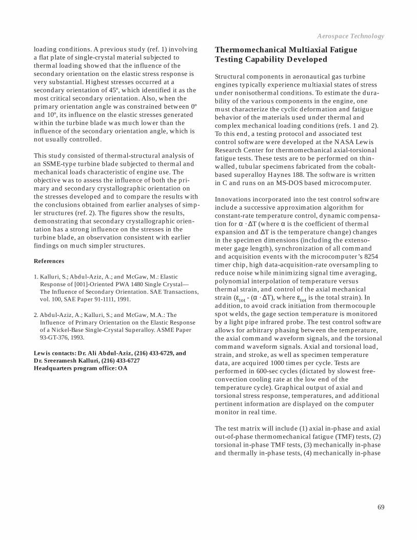
69
Aerospace Technology
loading conditions. A previous study (ref. 1) involvinga flat plate of single-crystal material subjected tothermal loading showed that the influence of thesecondary orientation on the elastic stress response isvery substantial. Highest stresses occurred at asecondary orientation of 45º, which identified it as themost critical secondary orientation. Also, when theprimary orientation angle was constrained between 0ºand 10º, its influence on the elastic stresses generatedwithin the turbine blade was much lower than theinfluence of the secondary orientation angle, which isnot usually controlled.
This study consisted of thermal-structural analysis ofan SSME-type turbine blade subjected to thermal andmechanical loads characteristic of engine use. Theobjective was to assess the influence of both the pri-mary and secondary crystallographic orientation onthe stresses developed and to compare the results withthe conclusions obtained from earlier analyses of simp-ler structures (ref. 2). The figures show the results,demonstrating that secondary crystallographic orien-tation has a strong influence on the stresses in theturbine blade, an observation consistent with earlierfindings on much simpler structures.
References
1. Kalluri, S.; Abdul-Aziz, A.; and McGaw, M.: Elastic Response of [001]-Oriented PWA 1480 Single Crystal— The Influence of Secondary Orientation. SAE Transactions, vol. 100, SAE Paper 91-1111, 1991.
2. Abdul-Aziz, A.; Kalluri, S.; and McGaw, M.A.: The Influence of Primary Orientation on the Elastic Response of a Nickel-Base Single-Crystal Superalloy. ASME Paper 93-GT-376, 1993.
Lewis contacts: Dr. Ali Abdul-Aziz, (216) 433-6729, andDr. Sreeramesh Kalluri, (216) 433-6727Headquarters program office: OA
Thermomechanical Multiaxial FatigueTesting Capability Developed
Structural components in aeronautical gas turbineengines typically experience multiaxial states of stressunder nonisothermal conditions. To estimate the dura-bility of the various components in the engine, onemust characterize the cyclic deformation and fatiguebehavior of the materials used under thermal andcomplex mechanical loading conditions (refs. 1 and 2).To this end, a testing protocol and associated testcontrol software were developed at the NASA LewisResearch Center for thermomechanical axial-torsionalfatigue tests. These tests are to be performed on thin-walled, tubular specimens fabricated from the cobalt-based superalloy Haynes 188. The software is writtenin C and runs on an MS-DOS based microcomputer.
Innovations incorporated into the test control softwareinclude a successive approximation algorithm forconstant-rate temperature control, dynamic compensa-tion for α · ∆T (where α is the coefficient of thermalexpansion and ∆T is the temperature change) changesin the specimen dimensions (including the extenso-meter gage length), synchronization of all commandand acquisition events with the microcomputer’s 8254timer chip, high data-acquisition-rate oversampling toreduce noise while minimizing signal time averaging,polynomial interpolation of temperature versusthermal strain, and control of the axial mechanicalstrain (εtot - (α · ∆T), where εtot is the total strain). Inaddition, to avoid crack initiation from thermocouplespot welds, the gage section temperature is monitoredby a light pipe infrared probe. The test control softwareallows for arbitrary phasing between the temperature,the axial command waveform signals, and the torsionalcommand waveform signals. Axial and torsional load,strain, and stroke, as well as specimen temperaturedata, are acquired 1000 times per cycle. Tests areperformed in 600-sec cycles (dictated by slowest free-convection cooling rate at the low end of thetemperature cycle). Graphical output of axial andtorsional stress response, temperatures, and additionalpertinent information are displayed on the computermonitor in real time.
The test matrix will include (1) axial in-phase and axialout-of-phase thermomechanical fatigue (TMF) tests, (2)torsional in-phase TMF tests, (3) mechanically in-phaseand thermally in-phase tests, (4) mechanically in-phase

70
and thermally out-of-phase tests, (5) mechanically out-of-phase and thermally in-phase tests, and (6) mechan-ically out-of-phase and thermally out-of-phase tests.The maximum and minimum temperatures for all testswill be 760 and 316 ºC, respectively. Results will be usedto assess multiaxial fatigue life models for their applica-bility to cyclic thermomechanical loading conditions.This program has been preceded by baseline experi-ments establishing the axial-torsional fatigue anddeformation characteristics of Haynes 188 at 760 and316 ºC.
References
1. Kalluri, S.; and Bonacuse, P.J.: Estimation of Fatigue Life Under Axial-Torsional Loading. PVP-Vol. 290, Material Durability/Life Prediction Modeling: Materials for the 21st Century, S.Y. Zamrik and G.R. Halford, eds., ASME, 1994, pp. 17-34.
2. Bonacuse, P.J.; and Kalluri, S.: Cyclic Axial-Torsional Deformation Behavior of a Cobalt-Base Superalloy. NASA TM-106372, 1994, pp. 204-229.
Lewis contacts: Peter J. Bonacuse, (216) 433-3309, andDr. Sreeramesh Kalluri, (216) 433-6727Headquarters program office: OA
Axial-torsional thermomechanical fatigue. Top: Schematic. Bottom: Mechanically out-of-phase andthermally out-of-phase cycles.
Fatigue Behavior and DeformationMechanisms in Inconel 718 SuperalloyInvestigated
The nickel-base superalloy Inconel 718 (IN 718) is usedas a structural material for a variety of components inthe space shuttle main engine (SSME) and accounts formore than half of the total weight of this engine. IN 718is the bill-of-material for the pressure vessels of nickel-hydrogen batteries for the space station. In the case ofthe space shuttle main engine, structural componentsare typically subjected to startup and shutdown loadtransients and occasional overloads in addition to high-frequency vibratory loads from routine operation. Thenickel-hydrogen battery cells are prooftested beforeservice and are subjected to fluctuating pressure loadsduring operation. In both of these applications, thestructural material is subjected to a monotonic loadinitially, which is subsequently followed by fatigue. Toassess the life of these structural components, it isnecessary to determine the influence of a prior mono-tonic load on the subsequent fatigue life of the super-alloy. An insight into the underlying deformation anddamage mechanisms is also required to properlyaccount for the interaction between the prior monotonicload and the subsequent fatigue loading.

71
Left: Influence of prior monotonic straining on the subsequent fatigue of IN 718 superalloy. Top right: Heavy localization ofdeformation in planar slip bands. IN 718 tested under a monotonic tensile strain of 10 percent followed by fatigue at a strain range of2 percent. Bottom right: Dislocation tangles within planar slip bands. IN 718 tested under a monotonic tensile strain of 10 percentfollowed by fatigue at a strain range of 0.8 percent.
An experimental investigation was conducted toestablish the effect of prior monotonic straining on thesubsequent fatigue behavior of wrought, double-aged,IN 718 at room temperature (ref. 1). First, monotonicstrain tests and fully-reversed, strain-controlled fatiguetests were conducted on uniform-gage-section IN 718specimens. Next, fully reversed fatigue tests wereconducted under strain control on specimens that weremonotonically strained in tension. Results from thisinvestigation indicated that prior monotonic strainingreduced the fatigue resistance of the superalloyparticularly at the lowest strain range. Some of thetested specimens were sectioned and examined bytransmission electron microscopy to reveal typicalmicrostructures as well as the active deformation anddamage mechanisms under each of the loading condi-tions (ref. 2). In monotonically strained specimens,deformation during the subsequent fatigue loading wasmainly confined to the deformation bands initiatedduring the prior monotonic straining. This can causedislocations to move more readily along the previouslyactivated deformation bands and to pile up near grainboundaries, eventually making the grain boundariessusceptible to fatigue crack initiation. The mechanismsinferred from the microstructural investigation wereextremely valuable in interpreting the influence of priormonotonic straining on the subsequent fatigue life ofInconel 718 superalloy.
103 10610510410–3
10–1
10–2
To
tal s
trai
n ra
nge,
Dε t Fatigue life
(no prestrain)
Tensile prestrain,percent
2
5
10
Cyclic life, Nf
References
1. Kalluri, S.; Halford, G.R.; and McGaw, M.A.: Pre-Straining and Its Influence on Subsequent Fatigue Life. NASA TM-106881, 1995.
2. Kalluri, S., et al.: Deformation and Damage Mechanisms in Inconel 718 Superalloy. Superalloys 718, 625, 706 and Various Derivatives. E.A. Loria, ed., The Minerals, Metals & Materials Society, Warrendale, PA, 1994, pp. 593-606.
Lewis contacts: Dr. Sreeramesh Kalluri, (216) 433-6727, andDr. Gary R. Halford, (216) 433-3265Headquarters program office: OA
Aerospace Technology

72
High-Temperature Extensometry and PdCrTemperature-Compensated Wire ResistanceStrain Gages Compared
A detailed experimental evaluation is underway at theNASA Lewis Research Center to compare and contrastthe performance of the PdCr/Pt dual-element tem-perature-compensated wire resistance strain gage withthat of conventional high-temperature extensometry(ref. 1). The advanced PdCr gage, developed byresearchers at Lewis, exhibits desirable properties anda relatively small and repeatable apparent strain to800 °C (refs. 2 and 3). This gage represents a significantadvance in technology because existing commercialresistance strain gages are not reliable for quasi-staticstrain measurements above ≈400 °C. Various thermaland mechanical loading spectra are being applied by ahigh-temperature thermomechanical uniaxial testingsystem to evaluate the two strain-measurementsystems. This is being done not only to compare andcontrast the two strain sensors, but also to investigatethe applicability of the PdCr strain gage to the coupon-level specimen testing environment typically employedwhen the high-temperature mechanical behavior ofstructural materials is characterized. Strain measure-ment capabilities to 800 °C are being investigated witha nickel-base superalloy, Inconel 100 (IN 100), substratematerial and application to TMC’s is being examinedwith the model system, SCS-6/Ti-15-3. Furthermore,two gage application techniques are being investigatedin the comparison study: namely, flame-sprayed andspot welding.
The apparent strain responses of both the weldable andflame-sprayed PdCr wire strain gages were found to becyclically repeatable on both IN 100 and SCS-6/Ti-15-3[0]8. In general, each gage exhibited some uniquenesswith respect to apparent strain behavior. Gages mount-ed on the IN 100 specimens tended to show a repeat-able apparent strain within the first few cycles, becausethe thermal response of IN 100 was stable. This wasnot the case, however, for the TMC specimens, whichtypically required several thermal cycles to stabilize thethermal strain response. Thus, progressive changes inthe apparent strain behavior were corroborated by theextensometer, which unlike the mounted gage can dis-tinguish quantitative changes in the material’s thermalstrain response. One specimen was instrumented withboth a fixed and floating gage. From the difference inoutput of these two gages, the thermal expansionstrains were calculated. These data, which are given inthe figure, show excellent agreement with the valuesmeasured by the high-temperature extensometry.
In general, the mechanical strain measurements fromthe gages and extensometer on both the IN 100 (to800 °C) and TMC (to 600 °C) were in relatively goodagreement (within 10 percent) to 2000 µε (microstrain).However, a slightly larger variation was found inthe low-temperature measurements on the IN 100specimen with the weldable gage. The weldable gagemounted on the TMC effectively failed with the initialloading. This failure was caused by a crack in theTIMETAL 21S shim at a spot-weld location. Dataobtained from this gage were, therefore, erroneoussince poor contact existed between the shim and thesubstrate composite. Subsequent to mechanical loadingcycles, the specimens were subjected to thermal cyclesto measure changes in the apparent strain responses. Ingeneral, the apparent strain responses of both theweldable and flame-sprayed gages were repeatable. Asa final aspect of mechanical performance in the presentwork, the specimens are being subjected to progres-sively increasing mechanical loads to measure themaximum mechanical strain threshold of the gages atroom temperature. Preliminary results indicate that thegages tended to lose reliable strain-measurementcapabilities at approximately 4500 µε.
References
1. Castelli, M.G.; and Lei, J.-F.: A Comparison Between High Temperature Extensometry and PdCr Based Resistance Strain Gages With Multiple Application Techniques. HITEMP Review 1994, NASA CP-10146, Vol. II, Oct. 1994, pp. 36-1 to 36-12. (Available to U.S. citizens only. Permis- sion to use this material was granted by Hugh R. Gray, January 1996.)
2. Lei, J.-F.: A Resistance Strain Gage With Repeatable and Cancellable Apparent Strain for Use to 800 °C. NASA CR- 185256, 1990.
3. Lei, J.-F.: Palladium-Chromium Static Strain Gages for High Temperatures. The 1992 NASA Langley Measurement Technology Conference Proceedings, NASA CP-3161, 1992, pp. 189-209.
Lewis contacts: Michael G. Castelli, (216) 433-8464, andDr. Jih-Fen Lei, (216) 433-3922Headquarters program office: OA
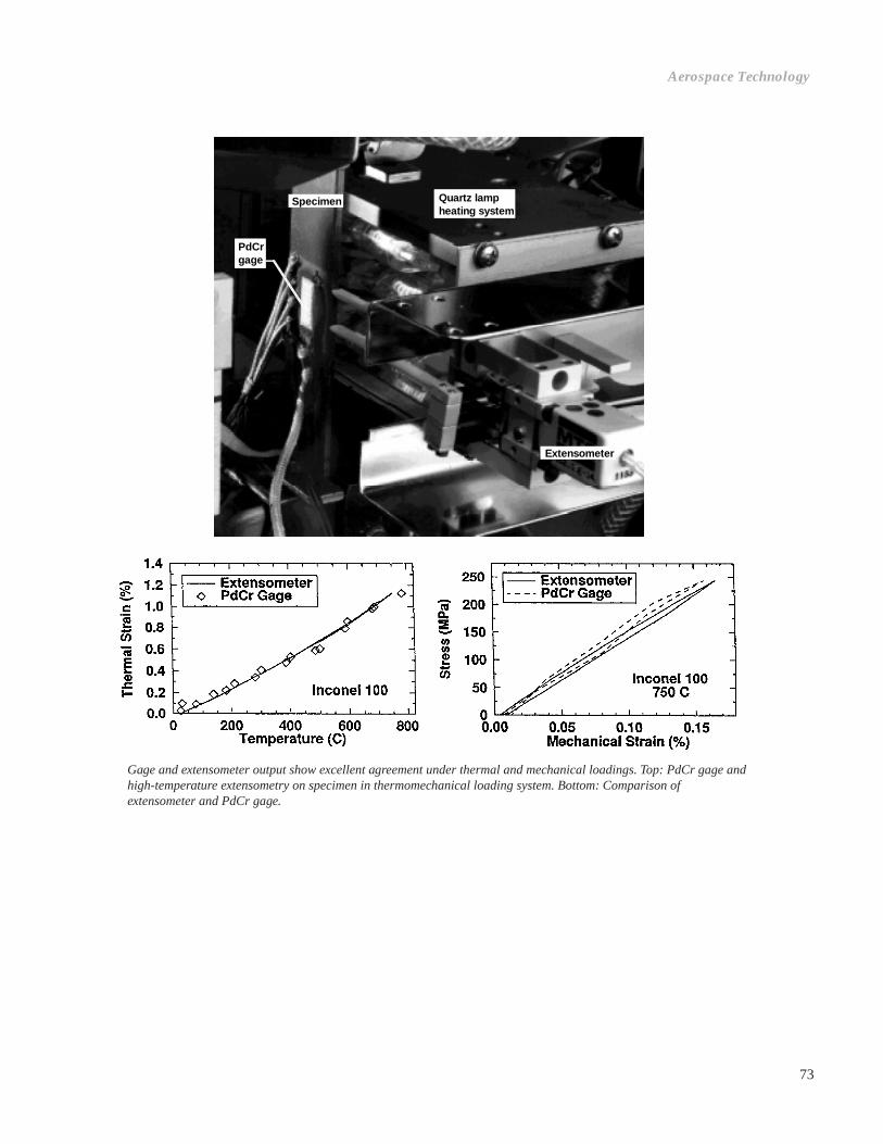
73
Gage and extensometer output show excellent agreement under thermal and mechanical loadings. Top: PdCr gage andhigh-temperature extensometry on specimen in thermomechanical loading system. Bottom: Comparison ofextensometer and PdCr gage.
Specimen Quartz lampheating system
Extensometer
PdCrgage
Aerospace Technology

74
Temperature-Dependent Effects on theMechanical Behavior and DeformationSubstructure of Haynes 188 UnderLow-Cycle Fatigue
The mechanical behavior of a cobalt-nickel-chromium-tungsten superalloy, Haynes 188, is being criticallyexamined at the NASA Lewis Research Center. Thisdynamic, strain-aging (DSA) alloy is used for combus-tor liners in many military and commercial aircraftturbine engines and for the liquid oxygen posts in themain injectors of the space shuttle main engine. Itsattractive features include a good combination of highmonotonic yield and tensile strength, and excellentfabricability, weldability, and resistance to high-temperature oxidation for prolonged exposures.
One of the current research activities on Haynes 188is investigating the effects of temperature on themechanical behavior and deformation substructureunder low-cycle fatigue (LCF) conditions over a rangeof temperatures between 25 and 1000 °C at a constantstrain rate of 10-3 sec-1. Particular attention is beinggiven to the effects of DSA on the stress-strain responseand the low-cycle fatigue life. Although DSA occursover a wide temperature range between 300 and 750 °C,the microstructural characteristics and the deformationmechanisms responsible for DSA vary considerablyand depend on temperature. Furthermore, DSA is notconsistently evidenced by serrated yielding or jerky
Cycles
Max
imum
ten
sile
str
ess,
MP
a
Cyclic stress response of Haynes 188 under low-cycle fatigue conditions with astrain range of ±0.4 percent and a strain rate of 10-3 sec-1.
flow, as is commonly exhibited in DSA alloys; however,specialized tests where the strain rate is changed atspecific cycles reveal a negative strain rate sensitivity,which is indicative of DSA. A correlation between thecyclic deformation behavior and the microstructuralprocesses is shown by detailed transmission electronmicroscopy investigations on material tested at varioustemperatures.
As shown in the figure, Haynes 188 exhibits a relativelycomplex temperature-dependent stress response. Attemperatures below 300 °C, the material exhibited aslight period of cyclic hardening followed by anextended period of essentially stable stress responseuntil the onset of failure. Here, cyclic deformationoccurred by simultaneous activation of two slipsystems. In the midtemperature regime from 400 to750 °C where DSA occurs, the material exhibitedmarked cyclic hardening prior to the onset of failure. Inthis regime, two slip systems were also activated, withthe deformation substructure exhibiting much higherdislocation densities than those revealed at 300 °C andbelow. Between 650 and 750 °C, dislocations weredistributed more homogeneously and were pinned byfine chromium-rich carbides, leading to enhanced cyclic

75
hardening. Above approximately 800 °C, the tendencyfor cyclic hardening declined, displaying cyclicsoftening at temperatures above 900 °C. At 900 °C andabove, dynamic recovery by thermally activated climbbecame prominent and lead to the formation of cellsand subgrains.
The crack initiation and propagation modes also weretemperature dependent in Haynes 188 under low-cyclefatigue conditions. At temperatures lower than 600 °C,crack initiation and propagation occurred in a trans-granular mode. In the range between 650 and 750 °C,crack propagation occurred by a mixed transgranularplus intergranular mode, despite the fact that the crackinitiation occurred by transcrystalline mechanisms. Forspecimens fatigued above approximately 800 °C, thefracture surfaces were covered with a thick oxidationlayer. At these relatively high temperatures, theapparent predominant mechanism for crack initiationand propagation was environmentally assistedintergranular cracking.
Lewis contact: Michael G. Castelli (216) 433-8464Headquarters program office: OA
New Method Developed for AeroelasticStability Analysis
The development of advanced-design ultrahigh bypassratio engines has led to renewed interest in the study ofthe flutter of bladed disks. Previously, two fundamentalapproaches were used in flutter calculations: frequencydomain analysis and time-domain analysis. With thedevelopment of time-marching computational fluiddynamics (CFD) flow solvers, both approaches havebeen used with equal ease. In the present work at theNASA Lewis Research Center, substantial computa-tional savings have been achieved by applying anumerical eigensolver to a nonlinear, time-marchingfluid-structure interaction system solver for flutterprediction.
The numerical eigensolver works with the steady-flowsolution to determine the eigenvalues and eigenmodescorresponding to the fluid-structure interaction systemdirectly. It does not require a time history of forces onblades and subsequent Fourier transformation todetermine stability. Also, it avoids computationallyexpensive time-domain simulations of small perturba-tion responses, where several cycles of oscillation arerequired to determine the growth or decay of perturba-tions. With this new method, the computational savingsover the existing frequency and time-domain nonlinearmethods are of the order of 100 to 10,000. However,
note that fundamentally this is a small perturbation(linear) aeroelastic analysis, although steady-flownonlinearities are taken into account (e.g., bladethickness, blade camber, and shock waves).
In the present work, a numerical eigensystem solver,based on a Lanczos procedure, is applied to a two-dimensional, full-potential, cascade aeroelastic solver.Calculations are performed for a cascade geometryused in previous research. Frequency-and time-domainflutter calculations were previously performed for thisconfiguration. The steady solution is first obtained, asrequired in all such calculations. Then, the numericaleigensystem solver is used to calculate eigenvalues.
The eigenvalues obtained from this new approachindicate whether the aeroelastic system is stable orunstable. A comparison of the results from thisapproach with those from existing flutter determinationmethods shows that the new approach predicts thecorrect flutter condition. It shows good agreement influtter speed and flutter mode.
The numerical eigensystem analysis results in sub-stantial computer time savings in comparison to thefrequency- and time-domain solutions. It will allowthe use of nonlinear, time-marching solvers in routineaeroelastic design analysis. Because of the modularnature of the numerical eigensystem solver, it can bereadily adapted to other time-marching aeroelasticsolvers with minimal additional effort required on theresearchers’ part.
SAMPLE FLUTTER RESULTS FROMFULL-POTENTIAL AEROELASTIC CODEa
Bibliography
Mahajan, A.J.; Bakhle, M.A.; and Dowell, E.H.: A NewMethod for Aeroelastic Stability Analysis of Cascades UsingNonlinear, Time-Marching CFD Solvers. AIAA Paper 94-4396,1994.
Lewis contacts: George L. Stefko, (216) 433-3920, and MilindA. Bakhle, (216) 433-6037Headquarters program office: OA
Flutterparameter
Frequencydomain
Timedomain
Newmethod
Frequency 0.265 0.262 0.239
Velocity 13.35 13.45 13.65
a All values are nondimensional
Aerospace Technology
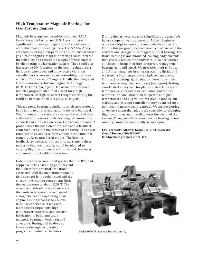
76
High-Temperature Magnetic Bearings forGas Turbine Engines
Magnetic bearings are the subject of a new NASALewis Research Center and U.S. Army thrust withsignificant industry participation, and coordinationwith other Government agencies. The NASA/Armyemphasis is on high-temperature applications for futuregas turbine engines. Magnetic bearings could increasethe reliability and reduce the weight of these enginesby eliminating the lubrication system. They could alsoincrease the DN (diameter of the bearing times rpm)limit on engine speed and allow active vibrationcancellation systems to be used—resulting in a moreefficient, “more electric” engine. Finally, the IntegratedHigh-Performance Turbine Engine Technology(IHPTET) Program, a joint Department of Defense/industry program, identified a need for a high-temperature (as high as 1200 ºF) magnetic bearing thatcould be demonstrated in a phase III engine.
This magnetic bearing is similar to an electric motor. Ithas a laminated rotor and stator made of cobalt steel.Wound around the stator are a series of electrical wirecoils that form a series of electric magnets around thecircumference. The magnets exert a force on the rotor. Aprobe senses the position of the rotor, and a feedbackcontroller keeps it in the center of the cavity. The enginerotor, bearings, and case form a flexible structure thatcontains a large number of modes. The bearingfeedback controller, which could cause some of thesemodes to become unstable, could be adapted tovarying flight conditions to minimize seal clearancesand monitor the health of the system.
Cobalt steel has a curie point greater than 1700 ºF, andcopper wire has a melting point beyondthat. Therefore, practical limitationsassociated with the maximum magneticfield strength in the cobalt steel and thestress in the rotating components limitthe temperature to about 1200 ºF. Theobjective of this effort is to determinethe limits in temperature and speed ofa magnetic bearing operating in anengine. Our approach is to use ourin-house experience in magnets,mechanical components, high-temperature materials, and surfacelubrication to build and test amagnetic bearing in both a rig andan engine. Testing will be done atLewis or through cooperativeprograms in industrial facilities. NASA 1000 ºF magnetic bearing test rig.
During the last year, we made significant progress. Wehave a cooperative program with Allison Engine towork on a high-temperature magnetic thrust bearing.During this program, we uncovered a problem with theconventional design of the magnetic thrust bearing. Thethrust bearing is not laminated, causing eddy currentsthat severely reduce the bandwidth. Also, we workedat Allison to bring their high-temperature magneticbearing rig to full speed. We predicted both in-houseand Allison magnetic bearing rig stability limits, andwe tested a high-temperature displacement probe.Our flexible casing rig is being converted to a high-temperature magnetic bearing rig (see figure). Testingshould start next year. Our plan is to develop a high-temperature, compact wire insulation and to fiberreinforce the core lamination to operate at highertemperatures and DN values. We plan to modify ourstability analysis and controller theory by including anonlinear magnetic bearing model. We are developingan expert system that adapts the controller to changingflight conditions and that diagnoses the health of thesystem. Then, we will demonstrate the bearing on ourrotor dynamics rig and, finally, in an engine.
Lewis contacts: Albert F. Kascak, (216) 433-6024, andGerald Brown, (216) 433-6047Headquarters program office: OA

77
Lewis-Developed Seals Serve GeneralElectric Technology Needs
Advanced aircraft engines require high-temperature,flexible seals to prevent backflow of high-temperaturecombustion gases. To meet this critical need, the NASALewis Research Center’s Structural Dynamics Branchdeveloped a line of hybrid braided-rope seals capableof high-temperature, high-pressure operation, whileconforming to and sealing complex engine structuresthat distort during operation. The seals operate attemperatures several hundred degrees above com-peting graphite seals. Another benefit is that they donot have the health hazards associated with competingasbestos-based seals that are now banned for most uses.
Being acquainted with Lewis’ high-temperature sealdevelopment, the General Electric Company (GE)worked with researchers in the Structural DynamicsBranch to determine if the braided rope seals could beused as a high-temperature compliant seal/mount forcomponents in one of GE’s advanced Integrated HighPerformance Turbine Engine Technology (IHPTET)demonstrator tests. These tests were sponsored by theU.S. Air Force Wright Laboratory’s Aero Propulsionand Power Directorate and the U.S. Navy. GE research-ers asked Lewis for assistance in solving a difficultsealing problem. Within GE’s rapid turnaroundrequirement of 4 months, Lewis successfully devel-oped, tested, and delivered the necessary seals. Theseseals are fabricated of a high-temperature, flow-resistant core of ceramic fibers overbraided with anabrasion-resistant sheath made of high-temperaturesuperalloy wires.
Advanced Alloy Development
For a number of years, GE has been developingadvanced alloys for high-temperature turbine bladesand vanes. Through GE’s considerable developmentefforts, complemented by the efforts of Lewis’ Materialsand Structures Division researchers, these advanced,high-temperature, oxidation-resistant intermetallicalloys have evolved to sufficient technical maturity tobe considered for the IHPTET program.
Vane/Seal Tests
Feasibility testing of the vane/seal systemdemonstrated that the compliant seal/mount showedpromise in reducing thermal stresses that develop inthe engine components exposed to combustiontemperatures, thereby increasing life. The advancedalloy vanes and the compliant seal/mount were thensuccessfully tested (last quarter of 1995) in a Joint
Technology Advanced Gas Generator (JTAGG) engine,meeting stringent IHPTET phase I and temperaturegoals. The hardware ran at temperatures severalhundred degrees Fahrenheit above conventionaltechnology vane/seal-mount systems. These testsconfirmed the viability of the vane and compliant seal/mount approach, paving the way for possible use infuture advanced military engines.
This project is an example of how, by working with ourindustry counterparts, Government researchers cansuccessfully transfer Government-developed technol-ogy to private industry. It is rewarding to have a majorcompany recognize that Government researchers pro-vide unique capabilities—solving technically challeng-ing problems and developing critical components inshort time periods.
Bibliography
Steinetz, B.M., et al.: High Temperature Braided Rope Sealsfor Static Sealing Applications. To be published as a NASATM, 1996.
Lewis contact: Dr. Bruce M. Steinetz; (216) 433-3302Headquarters program office: OA
Aerospace Technology
78
Lewis’ Ultrasonic Imaging TechnologyHelps American Manufacturer ofNondestructive Evaluation EquipmentBecome More Competitive in the GlobalMarket
Background
Sonix, Inc., of Springfield, Virginia, has implementedultrasonic imaging methods developed at the NASALewis Research Center. These methods have heretoforebeen unavailable on commercial ultrasonic imagingsystems and provide significantly more sensitivematerial characterization than conventional high-resolution ultrasonic c-scanning. The technologytransfer is being implemented under a cooperativeagreement (NCC3-385) between NASA and Sonix, andseveral invention disclosures have been submitted byDr. Roth to protect Lewis interests. Sonix has developedultrasonic imaging systems used worldwide formicroelectronics, materials research, and commercialnondestructive evaluation (NDE). In 1993, Sonix wonthe U.S. Department of Commerce “Excellence inExporting” award.
Lewis chose to work with Sonix for two main reasons:(1) Sonix is an innovative leader in ultrasonic imagingsystems, and (2) Sonix was willing to apply theimprovements we developed with our in-house Sonixequipment. This symbiotic joint effort has producedmutual benefits. Sonix recognized the market potentialof our new and highly sensitive methods for ultrasonicassessment of material quality. We, in turn, see thecooperative effort as an effective means for transferringour technology while helping to improve the product ofa domestic firm.
Significance
The Lewis-developed methods being implemented bySonix significantly enhance the materials characteri-zation by ultrasonic imaging. Among the benefits of theLewis methods is that it eliminates the effects of samplethickness variations. This isolates ultrasonic variationsdue to material microstructure and overcomes qualitycontrol problems during materials processing. Costsavings can be realized because the ultrasonic imagecan be correctly interpreted without additionalmachining to control sample thickness. Another benefitof our methods is that velocity variations may, in part,be imaged by ultrasound. This allows the quantitativecharacterization of microstructural factors, densitygradients, and associated mechanical properties. Theseattributes constitute a major improvement over thecapabilities of conventional ultrasonic methods.
Status
Sonix’ implementation of Lewis-developed methods iscurrently being beta-tested at Lewis. It is expected to beavailable for distribution to other Sonix system users byFebruary 1996.
Find out more about Lewis’ technology transfer programson the World Wide Web:http://www.lerc.nasa.gov/WWW/TU/techtran.htm
Lewis contact: Dr. Don J. Roth, (216) 433-6017Headquarters program office: OA
Integrated Design Software Predicts theCreep Life of Monolithic CeramicComponents
Significant improvements in propulsion and powergeneration for the next century will require revolu-tionary advances in high-temperature materials andstructural design. Advanced ceramics are candidatematerials for these elevated-temperature applications.As design protocols emerge for these material systems,designers must be aware of several innate features,including the degrading ability of ceramics to carrysustained load.
Usually, time-dependent failure in ceramics occursbecause of two different, delayed-failure mechanisms:slow crack growth and creep rupture. Slow crackgrowth initiates at a preexisting flaw and continuesuntil a critical crack length is reached, causing cata-strophic failure. Creep rupture, on the other hand,occurs because of bulk damage in the material: voidnucleation and coalescence that eventually leads tomacrocracks which then propagate to failure. Success-ful application of advanced ceramics depends onproper characterization of material behavior and theuse of an appropriate design methodology. The life of aceramic component can be predicted with the NASALewis Research Center’s Ceramics Analysis andReliability Evaluation of Structures (CARES) integrateddesign programs. CARES/CREEP determines theexpected life of a component under creep conditions,
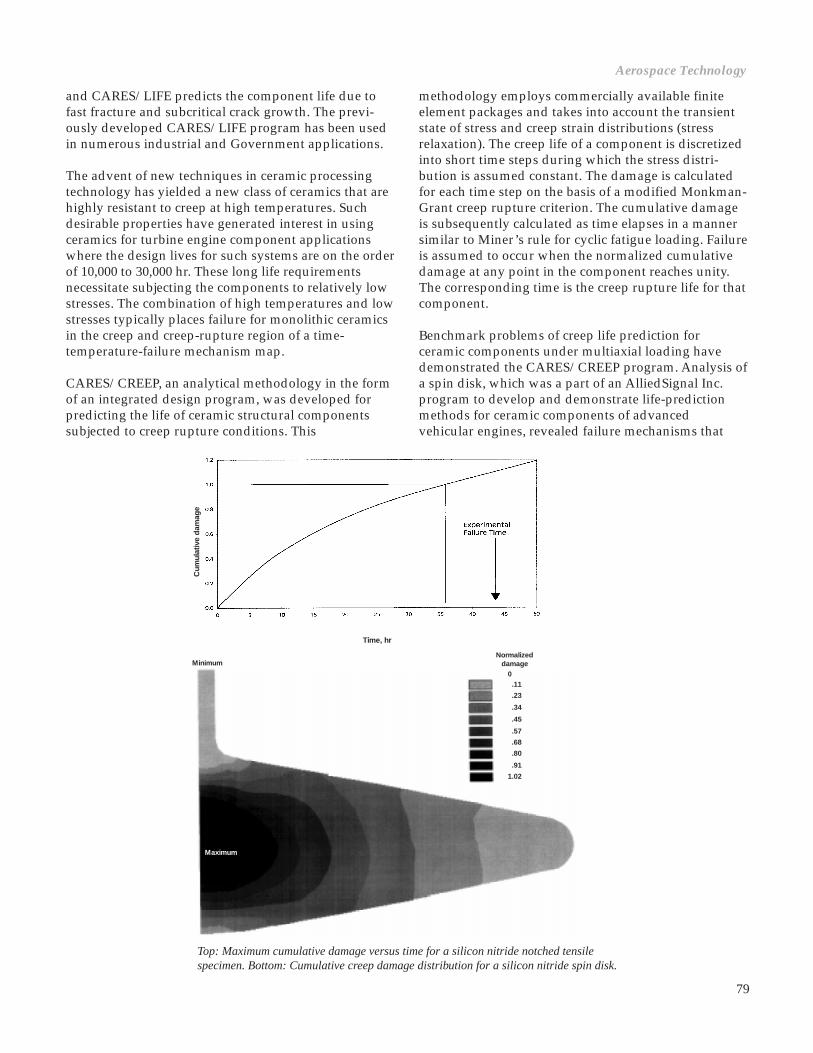
79
and CARES/LIFE predicts the component life due tofast fracture and subcritical crack growth. The previ-ously developed CARES/LIFE program has been usedin numerous industrial and Government applications.
The advent of new techniques in ceramic processingtechnology has yielded a new class of ceramics that arehighly resistant to creep at high temperatures. Suchdesirable properties have generated interest in usingceramics for turbine engine component applicationswhere the design lives for such systems are on the orderof 10,000 to 30,000 hr. These long life requirementsnecessitate subjecting the components to relatively lowstresses. The combination of high temperatures and lowstresses typically places failure for monolithic ceramicsin the creep and creep-rupture region of a time-temperature-failure mechanism map.
CARES/CREEP, an analytical methodology in the formof an integrated design program, was developed forpredicting the life of ceramic structural componentssubjected to creep rupture conditions. This
methodology employs commercially available finiteelement packages and takes into account the transientstate of stress and creep strain distributions (stressrelaxation). The creep life of a component is discretizedinto short time steps during which the stress distri-bution is assumed constant. The damage is calculatedfor each time step on the basis of a modified Monkman-Grant creep rupture criterion. The cumulative damageis subsequently calculated as time elapses in a mannersimilar to Miner’s rule for cyclic fatigue loading. Failureis assumed to occur when the normalized cumulativedamage at any point in the component reaches unity.The corresponding time is the creep rupture life for thatcomponent.
Benchmark problems of creep life prediction forceramic components under multiaxial loading havedemonstrated the CARES/CREEP program. Analysis ofa spin disk, which was a part of an AlliedSignal Inc.program to develop and demonstrate life-predictionmethods for ceramic components of advancedvehicular engines, revealed failure mechanisms that
Aerospace Technology
Normalizeddamage
0.11
.23
.34
.45
.57
.68
.80
.91
1.02
Minimum
Maximum
Top: Maximum cumulative damage versus time for a silicon nitride notched tensilespecimen. Bottom: Cumulative creep damage distribution for a silicon nitride spin disk.
Time, hr
Cum
ulat
ive
dam
age

80
were a combination of creep and slow crack growth.The second problem was a silicon nitride notchedtensile specimen, which was analyzed as a part of theSaint Gobain-Norton advanced heat engines applica-tions program. When the maximum damage in thenotched tensile specimen versus time is plotted, failureis expected to occur when the damage is equal to 1. Thepredicted failure time was 37 hr, whereas the actualfailure time was 44 hr, demonstrating a conservativeprediction.
The CARES/CREEP code predicts the deterministic lifeof a ceramic component. Future work involves the roleof probabilistic models in this design process. Thecomplete package will predict the life of monolithicceramic components by using simple uniaxial creeplaws to account for multiaxial creep loading. Thecombination of the CARES/CREEP and CARES/LIFEcodes gives the design engineer the tools necessary topredict component life for the two dominant delayed-failure mechanisms.
Lewis contact: Lesley A. Janosik, (216) 433-5160Headquarters program office: OA
Methodology Developed for Modeling theFatigue Crack Growth Behavior of Single-Crystal, Nickel-Base Superalloys
Because of their superior high-temperature properties,gas generator turbine airfoils made of single-crystal,nickel-base superalloys are fast becoming the standardequipment on today’s advanced, high-performanceaerospace engines. The increased temperature capa-bilities of these airfoils has allowed for a significantincrease in the operating temperatures in turbine sec-tions, resulting in superior propulsion performance andgreater efficiencies. However, the previously developedmethodologies for life-prediction models are based onexperience with polycrystalline alloys and may not beapplicable to single-crystal alloys under certainoperating conditions. One of the main areas wherebehavior differences between single-crystal and poly-crystalline alloys are readily apparent is subcriticalfatigue crack growth (FCG). Whereas in polycrystallinealloys cracks grow perpendicular to the applied load(i.e., mode I cracks), in single-crystal alloys cracks oftengrow on the operative slip planes that are inclined tothe applied load axis.
The NASA Lewis Research Center’s work in this areaenables accurate prediction of the subcritical fatigue
crack growth behavior in single-crystal, nickel-basedsuperalloys at elevated temperatures. Reference 1describes the limitations of the currently used mode Icrack-driving-force parameter and introduces two newparameters that are based on the resolved shear stresseson the individual slip systems present at the crack tip.The two parameters not only correlate the fatigue crackgrowth rates as a function of anisotropy but also areable to predict the operative slip system. These param-eters can be utilized in life-prediction models, which,when developed, will give a more accurate estimate ofthe life of the component since they will be based onthe actual deformation mechanisms by which pro-gressive failure occurs.
The experimental part of the program was performedin a specially designed, high-temperature, in situloading stage mounted inside a scanning electronmicroscope. This allowed for real-time observations ofthe operative failure modes at high magnifications. Theidentification of the ongoing failure mechanisms wasinstrumental in determining the conditions underwhich a given failure mode was active.
The influence of the environment on the fatigue crackgrowth behavior of the single-crystal alloy at elevatedtemperatures was also examined. We determined thatoxygen embrittlement at sufficiently low frequenciesand high temperatures is responsible for a transitionfrom an octahedral crack growth on the slip planes tothe mode I crack growth so prevalent in polycrystallinealloys.
20 mm
Octahedral mode crack growth process at 427 °C.

81
Reference
1. Telesman, J.; and Ghosn, L.: Fatigue Crack Growth Behavior of a PWA 1484 Single Crystal Superalloy at Elevated Temperatures. ASME Paper 95-GT-452, 1995.
Lewis contact: Jack Telesman, (216) 433-3310(World Wide Web URL:http://sdwww.lerc.nasa.gov/people/smteles.html)Headquarters program office: OA
Cra
ck g
row
th r
ate,
da/
dN
, m/c
ycle
10–5
10–6
10–7
10–8
10–9
100 101
Resolved shear stress intensity range,DKrss, MPa √m
1480-C52
1484-5
1484-4
1484-1
1484-8
1484-6
1484-3
Specimen
27
427
593
593
593
760
871
Temperature,°C
Rratio
0.5
0.5
0.5
0.7
0.1
0.5
0.5
Octahedral fatigue crack growth data plotted in terms of the ∆Krssparameter at various temperatures and R ratios.
Three Phases of Low-Cost Rocket EngineDemonstration Program Completed
The NASA Lewis Research Center and the TRW Space& Technology Group have successfully completed threephases of testing on the Low-Cost Rocket EngineDemonstration Program. TRW and the McDonnellDouglas Corporation are working, in a joint effort, toquickly develop and produce a highly stable, inexpen-sive, simple, yet reliable, expendable launch vehicle.Studies have shown that this launch system is requiredto maintain U.S. viability to space access in the face ofgrowing foreign competition. For the U.S. commerciallaunch industry to remain competitive, a low-costlaunch vehicle must be developed to place payloadsinto low-Earth orbit. Trade studies performed byMcDonnell Douglas and TRW have shown that a low-cost, commercial, expendable launch vehicle could bedesigned that uses low-pressure turbopumps androcket combustors. These studies show that expensivehigh-performance technology can be sacrificed forinexpensive lower performance technology and stillmeet mission requirements. Because the propulsionsystem is more than half of a launch vehicle’s cost, TRWproposed the pintle injector engine design used in theApollo Program—the lunar module descent engine.
TRW’s pintle injector engine, which runs on liquidhydrogen or RP-1 fuels and liquid oxygen oxidizer,uses modified low-pressure turbopumps to supply thepropellants. The engine consists of a centrally located,coaxial injector; an ablative liner for insulating themetal surfaces of the combustion chamber and nozzle;and annular sleeves to throttle the propellant feeds.
Lewis and TRW entered into a Space Act Agreementto demonstrate that the pintle injector can operate atacceptable stable performance levels and to demon-strate the life of a low-cost, combustion chamber withan ablative lining. The test program consisted of threephases: (1) testing a 16,500-lb-thrust liquid oxygen/liquid hydrogen (LOX/LH2) engine, (2) testing a40,000-lb-thrust LOX/LH2 engine, and (3) testing a13,000-lb-thrust LOX/RP-1 engine. All testing wasdone at Lewis’ Rocket Engine Test Facility (RETF).
The 16,500-lb-thrust engine was tested from December1991 through March 1992. Results show that the enginedelivered 95 to 97 percent characteristic velocity (C*)efficiency, about 2 to 4 percent higher than expected.
Space PropulsionTechnology
Aerospace Technology
√m

82
No combustion instabilities were exhibited, and theablative liner showed acceptable levels of ablation.
The 40,000-lb-thrust engine was tested from September1993 through February 1994 to determine scaling issuesand to demonstrate life of the flight-weight ablativeliner. The Lewis test results show that the enginedelivered 95-percent C* efficiency. The data indicate nocombustion instabilities, and the ablative liner showedacceptable levels of ablation (<0.006 in./sec).
The 13,000-lb-thrust liquid oxygen/RP-1 engine wastested from January 1995 through March 1995. TheC* efficiency demonstrated on this configuration was95 percent. The engine was stable in general but hadlow-frequency, rough combustion at startup because ofslow manifold filling, a minor design issue. Because ofa leaky pintle seal design, TRW’s pintle was damagedon several tests. This problem was soon corrected bythe Lewis team. During the ablative liner test, half ofthe throat region ablative liner fell out because it haddelaminated from the shell during fabrication. Theapproximate radius ablation rate was 0.013 in./sec.Using these test results, TRW and McDonnell Douglasare now working on expendable launch vehicleupgrades.
Bibliography
Dressler, G.A., et al.: Test Results from a Simple, Low-Cost,Pressure-Fed Liquid Hydrogen/Liquid Oxygen RocketCombustor. 1993 JANNAF Propulsion Meeting, Vol. 2, 1992,pp. 51-67.
Henneberry, J.P., et al.: Low-Cost Expendable LaunchVehicles. AIAA Paper 92-3433, 1992.
Klem, M.D.; Jankovsky, A.L.; and Stoddard, F.J.: Results ofLOX/RP-1 Pintle Injector Engine Tests. 32nd JANNAFCombustion Subcommittee Meeting, CPIA Publication 631,Vol. II, Oct. 1995.
Klem, M.D.; Wadel, M.F.; and Stoddard, F.J.: Results of 178KN (40,000 Lbf) Thrust LOX/LH2 Pintle Injector Engine Tests.32nd JANNAF Combustion Subcommittee Meeting, CPIAPublication 631, Vol. II, Oct. 1995.
Lewis contact: Mark D. Klem, (216) 977-7473Headquarters program office: OSAT
Combustion chamber with ablative liner tested with 40,000-lb-thrust liquid oxygen/liquidhydrogen.

83
High-Aspect-Ratio Cooling ChannelConcept Tested in Lewis’ Rocket EngineTest Facility
Rocket combustion chamber walls are exposed to thehigh-temperature environment caused by the combus-tion of propellants. Even with the walls actively cooledby the fuel, the hot gases can deteriorate the wallsseverely and limit any possibility for reusing thecombustion chamber. For many years, the NASA LewisResearch Center has performed subscale investigationsof potential improved cooling concepts to extend thelife and reliability of the combustion chamber. Resultsfrom previous subscale tests have shown that, byincreasing the coolant channel height-to-width aspectratio, the rocket combustion chamber hot-gas-side walltemperature can be reduced by as much as 28 percent,without an increase in the coolant pressure drop (ref. 1).Recently, a series of experiments were completed inLewis’ Rocket Engine Test Facility (RETF) to validatethe benefits of high-aspect-ratio cooling channels with ahigh-pressure, contoured rocket combustion chamber.
Validation of the high-aspect-ratio cooling channelconcept was done with a high chamber pressure,contoured combustion chamber (see photo) to simulatethe environment of a flight rocket engine. The com-bustion chamber had 100 conventional coolant channelsoutside of the critical heat flux area of the combustionchamber throat. These channels had a nominal aspectratio of 2.5. High-aspect-ratio cooling channels wereused in the critical heat flux area. The 100 conventionalcooling channels were bifurcated into 200 channels, andtheir aspect ratios were increased to a range of 5 to 8.The hot-gas-side wall temperature in the throat regionwas predicted to be approximately 1200 ºR. In com-parison, a similar combustion chamber with 100conventional coolant channels throughout the entirecombustion chamber length was predicted to havea hot-gas-side wall temperature of approximately1475 ºR. So that the hot-gas-side wall temperature couldbe verified experimentally, the combustion chamberwas heavily instrumented with 28 skin thermocouples,9 cooling channel rib thermocouples, and 10 coolingchannel pressure taps.
The combustion chamber was tested at chamberpressures from 800 to 1600 psia. The propellants weregaseous hydrogen and liquid oxygen at a nominalmixture ratio of 6, and liquid hydrogen was used as thecoolant. A total of 29 thermal cycles, each with 1 secof steady-state combustion, were completed on thecombustion chamber. For 25 thermal cycles, the coolantmass flow rate was equal to the fuel mass flow rate.During the remaining four thermal cycles, the coolant
mass flow rate was progressively reduced by 6 to18 percent.
Posttest analysis is being performed on the test dataand the combustion chamber. The preliminary resultsshow that the rib thermocouples were cooler thanpredicted; however, more analysis is required to realizethe full effect of this on the hot-gas-side wall tempera-ture. Visual examination of the combustion chamberafter testing revealed minimal deterioration in thecombustion chamber walls. The final results will bemade available so that future rocket engine designerscan take advantage of the high-aspect-ratio coolingchannel concept.
Bibliography
Carlile, J.A.; and Quentmeyer, R.J.: An ExperimentalInvestigation of High-Aspect-Ratio Cooling Passages. AIAAPaper 92-3154 (NASA TM-105679), 1992.
Lewis contacts: Mary F. Wadel, (216) 977-7510, andMichael L. Meyer, (216) 977-7492Headquarters program office: OSAT
High-aspect-ratio cooling channel combustion chamber.
Aerospace Technology

84
Fluid Film Bearing Code Development
The next generation of rocket engine turbopumps isbeing developed by industry through Government-directed contracts. These turbopumps will use fluidfilm bearings because they eliminate the life and shaft-speed limitations of rolling-element bearings, increaseturbopump design flexibility, and reduce the need forturbopump overhauls and maintenance. The design ofthe fluid film bearings for these turbopumps, however,requires sophisticated analysis tools to model thecomplex physical behavior characteristic of fluid filmbearings that are operating at high speeds with lowviscosity fluids. State-of-the-art analysis and designtools are being developed at the Texas A&M Universityunder a grant guided by the NASA Lewis ResearchCenter. Originally, Texas A&M was funded by theRocketdyne Division of Rockwell International andthen by Pratt & Whitney to develop the tools; but in1993, Lewis assumed responsibility for the effort.
The latest version of the code, HYDROFLEXT, is athermohydrodynamic bulk flow analysis with fluidcompressibility, full inertia, and fully developedturbulence models. It can predict the static anddynamic force response of rigid and flexible padhydrodynamic bearings and of rigid and tilting padhydrostatic bearings. The Texas A&M code is acomprehensive analysis tool, incorporating key fluidphenomenon pertinent to bearings that operate at highspeeds with low-viscosity fluids typical of those used inrocket engine turbopumps. Specifically, the energyequation was implemented into the code to enable fluidproperties to vary with temperature and pressure. Thisis particularly important for cryogenic fluids becausetheir properties are sensitive to temperature as well aspressure. As shown in the figure, predicted bearingmass flow rates vary significantly depending on thefluid model used. In addition, the Texas A&M codeaccounts for inertia in the thin-film region as well as atthe edge of hydrostatic bearing pockets. Becausecryogens are semicompressible fluids and the bearingdynamic characteristics are highly sensitive to fluidcompressibility, fluid compressibility effects are alsomodeled. In addition, a turbulence model must beincluded because of the high operating speeds and low-viscosity fluids encountered in cryogenic turbopumps.The code contains fluid properties for liquid hydrogen,liquid oxygen, and liquid nitrogen as well as for waterand air. Other fluids can be handled by the codeprovided that the user inputs information that relatesthe fluid transport properties to the temperature.
The Texas A&M bearing code has become the standardanalysis and design tool used by the rocket enginecommunity. This code is well accepted for use indesigning fluid film bearings because of confidence inits predictions. The code has been validated extensivelyby Texas A&M and Rocketdyne. In addition, Lewis hasjoined with the Air Force Phillips Laboratory to validatea key aspect of the analysis through a contracted effortwith Texas A&M. Under the direction of the Air Force,Texas A&M is conducting bearing tests using a mixtureof water and gaseous nitrogen to verify the code forfluid compressibility effects.
The Phillips Laboratory is interested in the code tosupport and guide their in-house hydrostatic bearingtest program, which will, in turn, provide data tofurther refine the code. Rocketdyne is presently using aversion of the code to design bearings for a low-costliquid oxygen turbopump being developed under aNASA Marshall Space Flight Center contract. Pratt &Whitney is also using a version of the code to supportturbopump development programs including theadvanced liquid hydrogen turbopump being developedfor the Air Force. In addition, Marshall acquired a copyof HYDROFLEXT to incorporate it into a shaft andbearing kinematic and thermal analysis code,SHABERTH. Previously, SHABERTH was limited torolling-element bearings.
0 0.6 1.00.80.40.2
1.2
1.4
0.8
0.6
No
rmal
ized
mas
s flo
w r
ate
Bearing eccentricity
1.0
Constant properties
Full variable properties
Linear properties
1.6
Predicted mass flow rate versus bearing eccentricity of a liquidhydrogen hydrostatic journal bearing for varying complexity fluidmodes.

85
The collaboration between NASA, the Air Force, andindustry resulted in the successful development of astate-of-the-art fluid-film-bearing analysis and designtool. The effort is expected to continue to completeenhancements and validation. Analysis for an angular-injected hydrostatic bearing model and a two-phaseflow model are presently being developed.
Bibliography
San Andres, L.: Turbulent Flow, Flexure-Pivot HybridBearings for Cryogenic Applications. Presented at the ASME/STLE Tribology Conference, Orlando, Florida, Oct. 8-11, 1995.ASME Paper 95-TRIB-14, 1995.
Lewis contact: James F. Walker, (216) 977-7465,Headquarters program office: OSAT
Cooperative Testing of Rocket Injectors ThatUse Gaseous Oxygen and Hydrogen
Gaseous oxygen and hydrogen propellants used in aspecial engine energy cycle called Full-Flow StagedCombustion are believed to significantly increase thelifetime of a rocket engine’s pumps. The cycle can alsoreduce the operating temperatures of the engine.Improving the lifetime of the hardware reduces itsoverall maintenance and operations costs, and is criticalto reducing costs for the joint NASA/industry ReusableLaunch Vehicle (RLV). The work in this project willdemonstrate the performance and lifetime of one-element and many-element combustors with gaseousO2/H2 injectors. This work supporting the RLV
program is a cooperative venture of the NASA LewisResearch Center, the NASA Marshall Space FlightCenter, Rocketdyne, and the Pennsylvania StateUniversity.
Information about gas-gas rocket injector performancewith O2/H2 is very limited (ref. 1). Because of thispaucity of data, new testing is needed to improve theknowledge base for testing and designing new injectorsfor the RLV and to improve computer models thatpredict the combusting gas flows of new injectordesigns. Therefore, detailed observations and measure-ments of the combusting flow from many-elementinjectors in a rocket engine are being sought. Theseobservations and measurements will be done withthree different tools: schlieren photography, ultravioletimaging, and Raman spectroscopy. The schlierensystem will take photos of the density differences incombusting flow, the ultraviolet movies will determinethe location of the hydroxyl (OH) radical in the com-bustion flow, and the Raman spectroscopic measure-ments will provide the combustion temperature andamount of water (H2O), hydrogen (H2), and oxygen(O2) in the combustor.
Marshall is providing overall program management,design and computational fluid dynamics (CFD)analyses, as well as funding for the work at Penn State.An existing, windowed combustor and several injectorswill be provided by Rocketdyne—two injectors for theinitial screening tests and one with an optimized designbased on the best design found in the screening tests.
Lewis will provide a nozzle and several injectors for thescreening test program. The configuration of the injec-tors will be based on a design chosen by all the parti-
cipants, and their elements will be based on thecoaxial and impinging flow. Lewis also willprovide the instrumentation for the flow-fieldmeasurements: schlieren, ultraviolet imaging,and Raman spectroscopy. In addition, thermo-couples will measure heat flow on the injectorface. Other traditional measurements of rocketperformance will be made as well: chamberpressure, mass flow of each propellant, purgeflow, and the barrier cooling gas flow. Penn Statewill conduct single-element testing with theinjector elements from both the Rocketdyne andthe jointly designed injectors.
A wide variety of traditional and nontraditionalinjector designs will be tested in this program.The results will be valuable in computationalfluid dynamics code validation and overallrocket combustion efficiency measurements.Gas-gas windowed combustion chamber during test firing.
Aerospace Technology

86
Correlations between combustion efficiency, lasermeasurements of species, and ultraviolet and visiblelight photography will also be made.
Thus far, several different single-element injectors havebeen tested at Penn State and Lewis. The figure showsthe experimental setup of a rocket engine with a view-ing window. The combusting flow is shown in therectangular window. The results are helping engineersdesign the many-element injectors.
References
1. Calhoon, D.F.; Ito, J.I; and Kors, D.L.: Investigation of Gaseous Propellant Combustion and Associated Injector- Chamber Design Guidelines. NASA CR-121234, 1973.
Lewis contact: Bryan A. Palaszewski, (216) 977-7493Headquarters program office: OSAT
Lessons Learned With Metallized GelledPropellants
During testing of metallized gelled propellants in arocket engine, many changes had to be made to thenormal test program for traditional liquid propellants.The lessons learned during the testing and the solutionsfor many of the new operational conditions posed withgelled fuels will help future programs run moresmoothly. The major factors that influenced the successof the testing were propellant settling, piston-cylindertank operation, control of self pressurization, capture ofmetal oxide particles, and a gelled-fuel protective layer.
In these ongoing rocket combustion experiments at theNASA Lewis Research Center, metallized, gelled liquidpropellants are used in a small modular engine thatproduces 30 to 40 lb of thrust. Traditional liquid RP-1and gelled RP-1 with 0-, 5-, and 55-wt % loadings ofaluminum are used with gaseous oxygen as theoxidizer (ref. 1). The figure compares the thrustchamber efficiencies of different engines.
Propellant Settling
After the gelled fuels are mixed and before this mixtureis put in the propellant transfer tank, the RP-1/Al mustbe stirred vigorously. During storage periods of 1 to10 days, the metal particles in the fuel begin to settlebecause of gravity, and a thin layer of clear RP-1 formsatop the fuel in its storage can. The fluid layer is about1-cm thick after about 10 days of storage. Ostwald
forces (refs. 2 and 3) promote clumping of the pro-pellant during storage.
Using a Piston-Cylinder Tank
In previous testing of gelled fuels (ref. 4), there wassome difficulty in feeding the metallized gelledJP-10/Al into the piston-cylinder tank. A manual stir-ring process was used to reduce the viscosity of thethixotropic fuel until a small pump could feed fuel intothe cylinder. To speed up this time-consuming fillingprocess, we fabricated a pressurized transfer tank to fillthe piston-cylinder tank. The transfer tank was chargedwith gelled fuel, and nitrogen pressurant was used toflow the fuel to the cylinder.
Propellant Self Pressurization
Experiments were conducted after we had anunplanned pressurization of the piston-cylinder tank.The propellant had been in the cylinder for several daysto several weeks, and the tank pressure had risen fromzero to several hundred pounds per square inch(gravimetric). In our testing operations we were unsureas to the fluid interactions, but high-pressure gas isgenerated when RP-1/Al is exposed to water. Toalleviate this problem for the short term, we replacedthe “pressurizing” fluid for the gelled propellant withhydraulic fluid. A series of tests that estimate the gas-generation rate from a mixture of RP-1/Al metallizedgelled fuel and a test fluid were conducted. The testfluids were water, hydraulic fluid, and Solvent 140.Although Solvent 140 and hydraulic fluid generatedlittle or no pressure, the water exposed to the RP-1/Alcreated significant pressures in some cases.
Comparison of rocket engine performance for four fuels: RP-1,and 0-, 5-, and 55-wt % RP-1/Al.
0
80
40
20
60
100
Thr
ust
cham
ber
eff
icie
ncy,
per
cent
RP-10 wt % 5 wt % 55 wt %
Gelled RP-1/Al
Propellant type

87
Particle Capturing
Rocket testing in Lewis’ Cell 21 uses a 9-ft-long tubulardiffuser with a series of circumferential water spraynozzles for cooling. This diffuser tube was augmentedwith an add-on tube (that added 3 ft of length) and a150-gal plastic tank to capture water from the coolingsystem and particles from the rocket exhaust. During afiring, the top of the tank was removed and the gaseousexhaust products were vented vertically away fromthe test cell. The water captured in the tank was runthrough a 10-µm filter before the water was exhaustedinto the laboratory area drain system. A small fractionof the metal particles were exhausted in this manner,but the bulk of the Al2O3 and other solid combustionproducts were captured in the cooling water flow. Thefilter did foul after a period of several days of testing,and when it fouled, it had to be changed. During theentire 1-year test period, we changed the filter at least8 to 10 times.
Gelled Propellant Protective Layer
During testing with the gelled RP-1 and the 5-wt %RP-1/Al, some residual propellant was found in therocket chamber, coating the entire injector face and allthe chamber walls. This residual propellant wasactually a mix of unburned fuel (with a gray or clearpink color) and some black or combustion products.Although none of the injector ports clogged, there wasa potential for the gel to obstruct the ports to a smalldegree. Once this thin layer was removed with a softcloth, the metal surfaces exhibited minimal erosion. Animproved cooling technique might be derived from thiseffect. The thickness of the layer is 1 to 2 mm for 0- and5-wt % RP-1/Al. The layer is easily wiped off with asoft cloth when the face is cleaned after disassembly.The gel layer also coats the injector such that the O2 andfuel flow form holes in the layer.
References
1. Palaszewski, B.; and Zakany, J.S.: Metallized Gelled Propellants: Oxygen/RP-1/Aluminum Rocket Combustion Experiments. AIAA Paper 95-2435 (NASA TM-107025),
2. Iler, R.K.: The Chemistry of Silica: Solubility, Polymerization, Colloid and Surface Properties, and Biochemistry, John Wiley and Sons, New York, 1979.
3. Selegny, E.: Charged Gels and Membranes—Part I. D. Reidel Publishing Company, Dordrecht, Holland, 1976.
4. Galecki, D.L.: Ignition and Combustion of Metallized Propellants. AIAA Paper 89-2883, 1989.
Lewis contact: Bryan A. Palaszewski, (216) 977-7493Headquarters program office: OSAT
1025:1 Area Ratio Nozzle Evaluated at HighCombustion Chamber Pressures
A recently completed experimental test programobtained performance data on an optimally contourednozzle with an exit-to-throat area ratio ε of 1025:1 andon a truncated version of this nozzle with an arearatio of 440:1. The nozzles were tested with gaseoushydrogen and liquid oxygen propellants at combustionchamber pressures of 12.4 to 16.5 mPa (1800 to 2400psia). Testing was conducted in the altitude test capsuleat the NASA Lewis Research Center’s Rocket EngineTest Facility (RETF), and results were compared withanalytical performance predictions. This testing buildson previous work with this nozzle at Lewis, wheretesting was completed at a nominal chamber pressureof 350 psia.
High-area-ratio nozzles have long been sought as ameans to increase the performance of space-basedrocket engines. However, as the area ratio increases, thephysical size and weight of the nozzle also increase. Asa result, engine and vehicle designers must make trade-offs between nozzle size and performance enhance-ment. Until this test program, very little experimentaldata existed on the performance of the high-area-rationozzles used in rocket engine designs. The computercodes being used by rocket engine designers rely ondata extrapolated from tests of low-area-ratio nozzles,and these extrapolations do not always provide theaccuracy needed for a reliable design assessment.Therefore, we conducted this high-area-ratio nozzletesting program to provide performance data for usein rocket engine design and analysis computer codes.
The nozzle had a nominal 2.54-cm- (1-in.-) diameterthroat, an exit diameter of 81.3-cm (32.0-in.) at ε = 1025,and a length of 128.6 cm (50.6 in.). Testing wasconducted in an altitude test capsule to simulate thestatic pressure at altitude by vacuum pumping. Datasuch as propellant mass flow, oxidizer-to-fuel mixture,and thrust were measured. These measurements werethen used to calculate performance factors such as thethrust coefficient CF, the characteristic exhaust velocityefficiency ηC*, and the vacuum specific impulse Isp. Inaddition, the nozzle temperature was measured tocalculate the amount of heat transferred from thecombustion gases to the nozzle.
1995.
Aerospace Technology

88
Diagnostics Adapted for Heat-TreatingFurnace Environment
Diagnostics developed for the in situ monitoring ofrocket combustion environments were adapted foruse in heat-treating furnaces. Simultaneous, in situmonitoring of the carbon monoxide, carbon dioxide,methane, water, and hydrogen concentrations in theendothermic gas of a heat-treating furnace weredemonstrated under a Space Act Agreement betweenthe NASA Lewis Research Center, the Heat TreatingNetwork, and Akron Steel Treating Company. Thisendothermic gas, or “endogas,” is produced in acatalytic process, where natural gas is “cracked” in thepresence of air. Variations in the composition of thenatural gas supplied lead to variations in the compo-sition of the endothermic gas. These variations couldlead to an unacceptable quality of steel products thatare hardened through the carborization process thatuses this gas.
Conventional methods of monitoring the endogasinclude measuring the dew point of the gas and theoxygen concentration. From these data, the carbonmonoxide content of the gas can be calculated. Thiscarbon monoxide concentration creates the carbonpotential needed for carburization. Several weak linksare present in this approach. The oxygen monitordeteriorates over time, and the measurement might beinaccurate by 50 percent. Also, the chemistry equations,which are based on several assumptions, such assecondary species concentrations, provide only anapproximate estimate of the carbon monoxideconcentration.
To address these weaknesses, we investigated a newmethod based on ordinary Raman spectroscopy, inwhich the carbon monoxide concentration is measureddirectly and in situ. This method measures the laserlight scattered from the molecules. Each species inter-acts with the light and scatters the light at a differentfrequency. Spectral monitoring of the scattered lightintensity at each molecular frequency of interestprovides the species concentrations. One advantageover the conventional method is that several speciescan be monitored simultaneously. A second advantageis that the measurement is direct; there is no need tomake assumptions, to filter the gas, or to calibrate theinstrument.
An instrument was designed consisting of a laser and adetection system within an enclosure, connected to anoptical probe by fibers. For determining carbon mon-oxide concentration, the probe is mounted on the
High-area-ratio nozzle on test stand.
References
1. Pavli, A.J.; Kacynski, K.J.; and Smith, T.A.: Experimental Thrust Performance of a High-Area-Ratio Rocket Nozzle. NASA TP-2720, 1987.
2. Smith, T.A.; Pavli, A.J.; and Kacynski, K.J.: Comparison of Theoretical and Experimental Thrust Performance of a 1030:1 Area Ratio Rocket Nozzle at a Chamber Pressure of 2413 kN/m2 (350 psia). AIAA Paper 87-2069 (NASA TP-2725), 1987.
3. Kacynski, K.J.; Pavli, A.J.; and Smith, T.A.: Experimental Evaluation of Heat Transfer on a 1030:1 Area Ratio Rocket Nozzle. AIAA Paper 87-2070 (NASA TP-2726), 1987.
4. Jankovsky, R.J.; Kazaroff, J.M.; and Pavli, A.J.: Experimental Performance of a High-Area-Ratio Rocket Nozzle at High Combustion-Chamber-Pressure, NASA TP- 3576, 1996.
Lewis contacts: Robert S. Jankovsky, (216) 977-7515, andTimothy D. Smith, (216) 977-7546Headquarters program office: OSAT
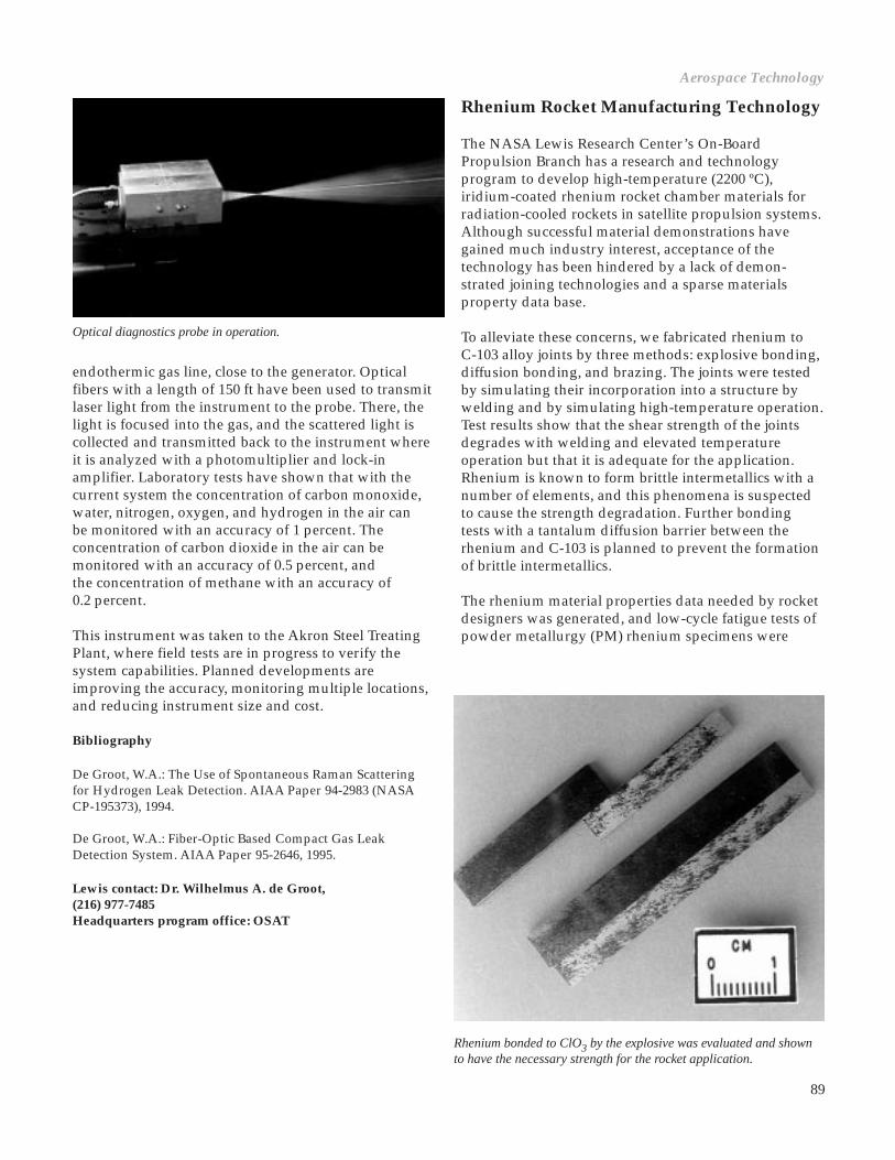
89
Optical diagnostics probe in operation.
endothermic gas line, close to the generator. Opticalfibers with a length of 150 ft have been used to transmitlaser light from the instrument to the probe. There, thelight is focused into the gas, and the scattered light iscollected and transmitted back to the instrument whereit is analyzed with a photomultiplier and lock-inamplifier. Laboratory tests have shown that with thecurrent system the concentration of carbon monoxide,water, nitrogen, oxygen, and hydrogen in the air canbe monitored with an accuracy of 1 percent. Theconcentration of carbon dioxide in the air can bemonitored with an accuracy of 0.5 percent, andthe concentration of methane with an accuracy of0.2 percent.
This instrument was taken to the Akron Steel TreatingPlant, where field tests are in progress to verify thesystem capabilities. Planned developments areimproving the accuracy, monitoring multiple locations,and reducing instrument size and cost.
Bibliography
De Groot, W.A.: The Use of Spontaneous Raman Scatteringfor Hydrogen Leak Detection. AIAA Paper 94-2983 (NASACP-195373), 1994.
De Groot, W.A.: Fiber-Optic Based Compact Gas LeakDetection System. AIAA Paper 95-2646, 1995.
Lewis contact: Dr. Wilhelmus A. de Groot,(216) 977-7485Headquarters program office: OSAT
Rhenium bonded to ClO3 by the explosive was evaluated and shownto have the necessary strength for the rocket application.
Rhenium Rocket Manufacturing Technology
The NASA Lewis Research Center’s On-BoardPropulsion Branch has a research and technologyprogram to develop high-temperature (2200 ºC),iridium-coated rhenium rocket chamber materials forradiation-cooled rockets in satellite propulsion systems.Although successful material demonstrations havegained much industry interest, acceptance of thetechnology has been hindered by a lack of demon-strated joining technologies and a sparse materialsproperty data base.
To alleviate these concerns, we fabricated rhenium toC-103 alloy joints by three methods: explosive bonding,diffusion bonding, and brazing. The joints were testedby simulating their incorporation into a structure bywelding and by simulating high-temperature operation.Test results show that the shear strength of the jointsdegrades with welding and elevated temperatureoperation but that it is adequate for the application.Rhenium is known to form brittle intermetallics with anumber of elements, and this phenomena is suspectedto cause the strength degradation. Further bondingtests with a tantalum diffusion barrier between therhenium and C-103 is planned to prevent the formationof brittle intermetallics.
The rhenium material properties data needed by rocketdesigners was generated, and low-cycle fatigue tests ofpowder metallurgy (PM) rhenium specimens were
Aerospace Technology

90
successfully conducted. These specimens passed a 100-cycle test sequence indicating that powder metallurgyrhenium can meet the service requirements of smallchemical rockets. Tensile properties of rheniumfabricated by chemical vapor deposition (CVD) andpowder metallurgy were evaluated from room tem-perature to 1900 ºC, and evaluations at 2200 ºC areplanned. These data indicate that either fabricationtechnique is viable. Rhenium creep tests also indicatethat the material is suitable for use in rocket chambersat the pressures and elevated temperatures anticipated.Enhancement of the iridium oxidation resistance alsowas demonstrated. A ceramic-oxide-coated, iridium-coated rhenium rocket chamber was successfully testedfor 32 hr on gaseous hydrogen/gaseous oxygen pro-pellants at a mixture ratio of 4. The oxidizer content inthese gases is similar to that of Earth storables, indica-ting that the oxide coating causes a factor of 5 increasein life over previously tested iridium/rheniumchambers.
Under a Space Act Agreement, the NASA-developedrhenium rocket technology enabled TRW to develop anAdvanced Dual Mode rocket with 328 sec of specificimpulse. This engine will be baselined on the LockheedMartin A2100 satellite, if it is flight qualified in the timeframe required.
Lewis contact: Dr. Steven J. Schneider, (216) 977-7484Headquarters program office: OSAT
NSTAR Ion Propulsion System PowerElectronics
High-specific-impulse ion propulsionsystems (IPS’s) have long been targetedas candidates for the primary propul-sion systems of both planetary andEarth-space spacecraft, and as auxiliarypropulsion systems for geosynchro-nous communications spacecraft.Major issues with ion propulsionsystems are the system cost andcomplexity, especially in the powerprocessing unit (PPU). In some cases,the PPU’s have contained over 4000discrete parts and 12 power suppliesto operate the thruster.
The NASA Solar Electric PropulsionTechnology Application Readiness
(NSTAR) program, managed by the Jet PropulsionLaboratory (JPL), is currently developing a high-performance, simplified ion propulsion system. Thispropulsion system, which is throttleable from 0.5- to2.3-kW output power to the thruster, targets primarypropulsion applications for planetary and Earth-spacemissions and has been baselined as the primarypropulsion system for the first New Millenniumspacecraft.
The NASA Lewis Research Center is responsible forthe design and delivery of a breadboard PPU and anengineering model thruster (EMT) for this system andwill manage the contract for the delivery of the flighthardware to JPL. The PPU requirements, which dictatea mass of less than 12 kg with an efficiency of 0.9 orgreater at a 2.3-kW output, forced a departure fromthe state-of-the-art ion thruster PPU design. Severalinnovations—including dual-use topologies, simpli-fied thruster control, and the use of ferrite magneticmaterials—were necessary to meet these requirements.
To reduce the level of complexity and parts count in thePPU, designers at Lewis employed a dual-use conceptfor the discharge and neutralizer power supplies. Thedual-use topology derives power for the cathode heaterand anode from the same power transformer, allowingthe construction of a single inverter each for the neu-tralizer and discharge power supplies. This topologyselection reduced the number of power suppliesnecessary to operate the thruster to four. Furthersimplifications were realized in the PPU with theapplication of a single closed loop, implemented in amicrocontroller, for thruster control. This loop regulatesthe beam current, and thus the thrust produced, byvarying the discharge current. Completed breadboardpower supplies are shown in the photograph.
Three breadboard power-supply modules.

91
To minimize mass and optimize the efficiency of thebreadboard, we set the switching frequency of thepower supplies which operate the thruster at 50 kHz.This frequency selection represents a compromisebetween low mass and high efficiency, and it alsoallows the power transformers to be designed andfabricated with ferrite (ceramic) cores. If packaging offerrite components for spaceflight becomes an issue,this frequency is still within the usable range of metalliccore transformers that have an extensive heritage inflight designs.
A breadboard version of the PPU was fabricated tovalidate the dual-use concept and verify closed-loopstability within the individual power supplies and withthe thruster. The breadboard, which was integratedwith a 30-cm ion thruster, demonstrated autonomouscontrol and stable steady-state operation of the thrusterover the full throttling range. The total component massof the breadboard as built is 6.2 kg, and the efficiency ison the order of 0.9. A simplified user interface facilitatesthruster operation via a data terminal, with thrusteroperations reduced to a single on/off command.
Lewis contact: John A. Hamley, (216) 977-7430Headquarters program office: OSAT (STD and SSD)
Pulsed Plasma Thruster Technology
The continuing emphasis on reducing costs and down-sizing spacecraft is forcing increased emphasis onreducing the subsystem mass and integration costs. Formany commercial, scientific, and Department ofDefense space missions, onboard propulsion is eitherthe predominant spacecraft mass or it limits the space-craft lifetime. Electromagnetic-pulsed-plasma thrusters(PPT’s) offer the combined benefits of extremely lowaverage electric power requirements (1 to 150 W), highspecific impulse (~1000 sec), and system simplicityderived from the use of an inert solid propellant.Potential applications range from orbit insertion andmaintenance of small satellites to attitude control forlarge geostationary communications satellites.
Although PPT’s have operated on several spacecraft,there has been no new PPT technology developmentsince the early 1970’s. As a result of rapid growth in thesmall satellite community and the broad range of PPTapplications, the NASA Lewis Research Center hasinitiated a development program to dramaticallyreduce the PPT dry mass, increase PPT performance,and demonstrate a flight-ready system by October 1997.The flight system is being built under a contract with
LES 8/9 pulsed-plasma thruster mounted on the JAWSAT spacecraft bus in preparation forintegration testing at Lewis.
Aerospace Technology

92
Olin Aerospace. A recent report (ref. 1) summarizedthe results of a series of near-Earth mission studies,including both primary and auxiliary propulsion andattitude control functions and reviewed the status ofNASA’s ongoing development program.
The baseline technology for the new developmentprogram is the Lincoln Experimental Satellite (LES) 8/9PPT, which was flight qualified in 1970 with a fueledsystem mass of 7.0 kg and provides 10,000-N-sec totalimpulse. The program objectives are to decrease thefueled system mass to 3.5 kg while doubling the totalimpulse capability to 20,000 N-sec. These objectives arebeing accomplished via the use of recently developedcapacitors, integrated circuit technology for bothtelemetry and power electronics, new structuralmaterials, and an increase in PPT performance.
Efforts to date have demonstrated a factor of 2 reduc-tion in mass and volume for the power converter,ignition, and logic/telemetry systems. In addition,lightweight capacitors have been selected and areundergoing life testing in a new PPT dischargesimulator. Spacecraft integration assessments are alsounderway, with testing of contamination, electromag-netic interference, and Global Positioning Systemcompatibility. This testing is currently focused onintegrating an old LES 8/9 PPT on the Joint Air Force/Weber State University Satellite (JAWSAT), a smalleducational satellite to be launched in 1997 (see figure).The PPT program is on target to deliver a new,lightweight flight-qualified system in October 1997.
Reference
1. Myers, R., et al.: Pulsed Plasma Thruster Technology for Small Satellite Missions. NASA CR-198427, 1995.
Lewis contact: Dr. Roger M. Myers, (216) 977-7426Headquarters program office: OSAT
Thermodynamic Vent System Applied asPropellant Delivery System for Air Force
Responding to a request from the Air Force, NASALewis Research Center engineers designed a com-bination pressure control and propellant deliverysystem based on thermodynamic vent system (TVS)technology. The Air Force is designing a new type oforbit transfer vehicle that uses energy from sunlight toboth propel and power the vehicle. Because this vehicleuses propellant at a substantially slower rate thanhigher-energy rockets, it needed the Lewis-developedTVS technology for long-duration storage of cryogenpropellants. Lewis engineers, in conjunction withindustry partners, showed how this TVS technologycould also be used to deliver propellant to the thruster.The Air Force has now begun the ground test demon-stration phase. After successful completion of groundtesting, the Air Force plans to use this technology in aspace flight as early as 1999.
To reduce satellite operation costs, the Air Force isdesigning an Integrated Solar Upper Stage (ISUS) totransport communication satellites from low-Earthorbit to higher operational orbits. This vehicle usessolar concentrators for both propulsive heating of thehydrogen propellant and thermionic power generationonce the vehicle has reached its operational orbit.Because the payload and spacecraft system areintegrated into a common unit and because thepropulsion method has a higher specific impulse thanconventional upper stages do, the Integrated SolarUpper Stage can use smaller and less-expensive launchvehicles to deliver the same mass as conventionalupper stages.
For this application, the Air Force needed a propellantstorage and delivery system with the following charac-teristics: (1) a minimum-volume, cryogenic liquidhydrogen tank, (2) no propellant venting except thatwhich occurs as a part of orbit transfer burns, (3) a30-day orbit transfer with a nonconstant burn schedule,(4) a high ratio of tank lockup durations to burndurations, and (5) the option to hold the propellants atlow orbit for 3 to 7 days before the orbit transfer.
These challenges were met by the Lewis/industryteam’s conceptual design, shown in the figure. Tominimize tank volume, the team used a low-pressure,low-ullage tank (0.3 MPa, 3-percent ullage). A multi-layer insulation system reduces heat leaks into the tank,but it is designed to allow enough background heat into

93
the tank to pressurize the system. A TVS, originallydesigned for controlling tank pressures for long-duration cryogen storage, simultaneously deliverspropellant to the thruster and removes heat from thetank. The resulting pressure drop during each burn istailored so that the operating pressure will be recoveredby background heating before the next burn. Because ofthe nonconstant burn schedule and uncertainties aboutthe heat rate and corresponding pressure rise inmicrogravity environments, a TVS incorporating anintegral mixer and heat exchanger with an activecontroller is used. The mixer can also be used between
Thermodynamic vent system applied as propellant delivery system for air force integrated solar upperstage—propellant tank cutaway.
burns to control tank pressure. A heater included in thesystem can add heat to the tank if needed.
The next major step of the program is the engineground demonstration to be conducted in Lewis testfacilities (1997). It will demonstrate vehicle operationover a simulated mission profile. Success of the groundtesting may lead to a flight mission as early as 1999.
Lewis contact: Marc G. Millis, (216) 977-7535Headquarters program office: OSAT
Aerospace Technology

94
Power Technology
SCARLET Solar Array Delivered forMETEOR Mission
Solar Concentrator Array with Refractive LinearElement Technology (SCARLET) is a joint NASA LewisResearch Center/Ballistic Missile Defense Organizationprogram to develop advanced photovoltaic arraytechnology for future space missions. This advancedpower system technology uses a unique refractiveconcentrator design to focus sunlight onto a line ofphotovoltaic cells located below the optical element.The concentrator design is based on previous workconducted at Lewis under a Small Business InnovationResearch Program (SBIR) with Entech, Inc.
SCARLET technology offers a number of advantagesfor future spacecraft systems. In addition to thepotential benefits of providing a high-efficiency arrayat a low cost, its inherent resistance to degradation in ahigh-radiation environment makes this technologyextremely attractive for a number of future Govern-ment and commercial missions. The demonstratedbenign behavior of concentrator arrays with respect toplasma interactions also makes SCARLET a desiredpower source for missions involving electric propulsiontechnology.
Small prototype samples of refractive concentratortechnology had flown previously;however, concentrators had not beendemonstrated in space at the “arraylevel.” When an opportunity to fly aSCARLET array on the first flight of theMultiple Experiments to Earth Orbitand Return (METEOR) spacecraftarose, an industry team led by AEC-Able Engineering, Inc., was contractedto design, build, and test the array. Amajor problem presented by this flightopportunity was the tight scheduleinvolved. To meet the original launchschedule, we needed to move theSCARLET-METEOR program from theexisting prototype componenthardware to a new flight-qualifiedsolar array within a 6-month period.Despite the expected problems asso-ciated with the development of newtechnology, a self-contained, fullydeployable array was fabricated, flighttested, and delivered for spacecraftintegration within the specified time.
The nominal 200-W array was designed not only toprovide valuable in-flight data on SCARLET deploy-ment, performance, and long-term operations, butalso to supplement power to the spacecraft bus.
Despite the success of the SCARLET-METEOR hard-ware development program, failure of the Conestogalaunch vehicle on October 23, 1995, prevented actualorbital data from being obtained on this array.However, the development of the METEOR flighthardware provided a basis from which the SCARLETprogram will continue. The lessons learned and thetechniques developed under SCARLET-METEOR willprovide invaluable experience as hardware isdeveloped for a variety of future space missions.
For more information about SCARLET, visit our site on theWorld Wide Web:http://powerweb.lerc.nasa.gov/psi/DOC/scarlet.html
Lewis contact: Michael F. Piszczor, (216) 433-2237Headquarters program office: OSAT
SCARLET-METEOR solar array flight hardware shown in a deployed configuration.
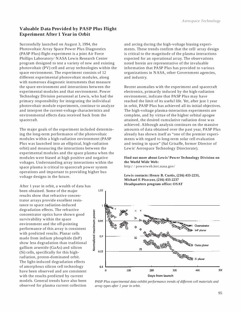
95
Valuable Data Provided by PASP Plus FlightExperiment After 1 Year in Orbit
Successfully launched on August 3, 1994, thePhotovoltaic Array Space Power Plus Diagnostics(PASP Plus) flight experiment is a joint Air ForcePhillips Laboratory/NASA Lewis Research Centerprogram designed to test a variety of new and existingphotovoltaic (PV) cell and array technologies within thespace environment. The experiment consists of 12different experimental photovoltaic modules, alongwith numerous diagnostic instruments that measurethe space environment and interactions between theexperimental modules and that environment. PowerTechnology Division personnel at Lewis, who had theprimary responsibility for integrating the individualphotovoltaic module experiments, continue to analyzeand interpret the current-voltage characteristics andenvironmental effects data received back from thespacecraft.
The major goals of the experiment included determin-ing the long-term performance of the photovoltaicmodules within a high-radiation environment (PASPPlus was launched into an elliptical, high-radiationorbit) and measuring the interactions between theexperimental modules and the space plasma when themodules were biased at high positive and negativevoltages. Understanding array interactions within thespace plasma is critical to spacecraft power systemoperations and important to providing higher busvoltage designs in the future.
After 1 year in orbit, a wealth of data hasbeen obtained. Some of the majorresults show that refractive concen-trator arrays provide excellent resis-tance to space radiation-induceddegradation effects. The refractiveconcentrator optics have shown goodsurvivability within the spaceenvironment and the off-pointingperformance of this array is consistentwith predicted results. Planar cellsmade from indium phosphide (InP)show less degradation than traditionalgallium arsenide (GaAs) and silicon(Si) cells, specifically for this high-radiation, proton-dominated orbit.The light-induced degradation effectsof amorphous silicon cell technologyhave been observed and are consistentwith the results predicted by currentmodels. General trends have also beenobserved for plasma current collection
Days from launch
and arcing during the high-voltage biasing experi-ments. These trends confirm that the cell/array designis critical to the magnitude of the plasma interactionsexpected for an operational array. The observationsnoted herein are representative of the invaluableinformation that PASP Plus has provided to variousorganizations in NASA, other Government agencies,and industry.
Recent anomalies with the experiment and spacecraftelectronics, primarily induced by the high-radiationenvironment, indicate that PASP Plus may havereached the limit of its useful life. Yet, after just 1 yearin orbit, PASP Plus has achieved all its initial objectives.The high-voltage plasma-interaction experiments arecomplete, and by virtue of the higher orbital apogeeattained, the desired cumulative radiation dose wasachieved. Although analysis continues on the massiveamounts of data obtained over the past year, PASP Plusalready has shown itself as “one of the premier experi-ments with regard to long-term solar cell evaluationand testing in space” (Sal Grisaffe, former Director ofLewis' Aerospace Technology Directorate).
Find out more about Lewis’ Power Technology Division onthe World Wide Web:http://powerweb.lerc.nasa.gov/
Lewis contacts: Henry B. Curtis, (216) 433-2231,Michael F. Piszczor, (216) 433-2237Headquarters program office: OSAT
PASP Plus experimental data exhibit performance trends of different cell materials andarray types after 1 year in orbit.
No
rmal
ized
max
imum
po
wer
Aerospace Technology

96
Separator Materials Used in SecondaryAlkaline Batteries Characterized andEvaluated
Nickel-cadmium (Ni/Cd) and nickel-hydrogen(Ni/H2) secondary alkaline batteries are vital toaerospace applications. Battery performance and cyclelife are significantly affected by the type of separatorsused in those batteries. A team from NASA LewisResearch Center’s Electrochemical Technology Branchdeveloped standardized testing procedures tocharacterize and evaluate new and existing separatormaterials to improve performance and cycle life ofsecondary alkaline batteries.
Battery separators must function as good electronicinsulators and as efficient electrolyte reservoirs. Atpresent, new types of organic and inorganic separatormaterials are being developed for Ni/Cd and Ni/H2batteries. The separator material previously used in theNASA standard Ni/Cd was Pellon 2505, a 100-percentnylon-6 polymer that must be treated with zincchloride (ZnCl2) to bond the fibers. Because of stricterEnvironmental Protection Agency regulation of ZnCl2emissions, the battery community has been searchingfor new separators to replace Pellon 2505. As of today,two candidate separator materials have been identified;however, neither of the two materials have performed
as well as Pellon 2505. The separator test proceduresthat were devised at Lewis are being implemented toexpedite the search for new battery separators.
The new test procedures, which are being carried out inthe Separator Laboratory at Lewis, have been designedto guarantee accurate evaluations of the properties thatare critical for sustaining proper battery operation.These properties include physical and chemical sta-bility, chemical purity, gas permeability, electrolyteretention and distribution, uniformity, porosity, andarea resistivity. A manual containing a detaileddescription of 12 separator test procedures has beendrafted and will be used by the battery community toevaluate candidate separator materials for specificapplications. These standardized procedures will allowfor consistent, uniform, and reliable results that willensure that separator materials have the desiredproperties for long life and good performance insecondary alkaline cells.
Lewis contact: Edwin Guasp, (216) 433-5249Headquarters program office: OSMA
Bubble Pressure Test Apparatus for determination of gas permeabilities across a batteryseparator.

97
Regenerative Fuel Cell System TestbedProgram for Government and CommercialApplications
NASA Lewis Research Center’s ElectrochemicalTechnology Branch has led a multiagency effort todesign, fabricate, and operate a regenerative fuel cell(RFC) system testbed. Key objectives of this programare to evaluate, characterize, and demonstrate fullyintegrated RFC’s for space, military, and commercialapplications. The Lewis-led team is implementing theprogram through a unique international coalition thatencompasses both Government and industry partici-pants. Construction of the 25-kW RFC testbed at theNASA facility at Edwards Air Force Base was com-pleted in January 1995, and the system has beenoperational since that time.
RFC systems can provide efficient, environmentallybenign, highly reliable, renewable energy conversionfor a variety of applications. These systems consist ofthe following subsystems: fuel cells, electrolyzers,photovoltaic arrays, reactant storage, thermal man-agement, and electrical power management. Fuel cellsconsume hydrogen and oxygen (or air) to produce
electricity, water, and heat. The product water is storedand later dissociated into its hydrogen and oxygenconstituents by a solar-powered electrolyzer. Thehydrogen and oxygen are then stored for subsequentfuel cell consumption, and the fuel cell waste heat canbe utilized in many different ways. If the fuel cell isdesigned to consume air rather than pure oxygen, thenthe oxygen from water electrolysis is available for otheruses, such as in biological waste purification. For manyyears, individual RFC subsystem components havebeen under development for nonregenerativeapplications. The objectives of the Lewis testbedprogram are to design, test, and evaluate RFC’s tocharacterize system life, performance, and integrationissues for candidate RFC system technologies. Thetestbed is generic in the sense that it can be used toevaluate the different technologies that are specific tospace, military, and commercial needs.
Lewis contact: Dr. Marvin Warshay, (216) 433-6126Headquarters program office: OSAT (SSD)
High power density fuel cell.
Aerospace Technology
98
In the first phase of the PBW program, power systemdefinitions and requirements will be developed. Apower management and distribution (PMAD) archi-tecture that best meets the system requirements willbe designed, fabricated, and tested. Several electricalactuators will be designed, fabricated, and demon-strated; and a starter/generator that best meets thesystem requirements will be designed, fabricated, anddemonstrated.
A redundant electrical actuator subsystem developedunder the PBW portion of the FBL/PBW program willbe delivered to Langley to be integrated into theTransport Systems Research Vehicle (TSRV) 757 for aflight demonstration in 1999. The flight demonstrationwill consist of a fault-tolerant control subsystem, afault-tolerant power subsystem, an electrical actuatorsubsystem, and optic sensors.
A PBW program contract was signed with McDonnellDouglas in September 1993, the specifications andrequirements documents were completed and deliveredin April 1995, the preliminary flight actuator designwas completed in July 1995, and a preliminary designreview of the program was completed in November1995.
Lewis contacts: David D. Renz, (216) 433-5321, andLinda M. Taylor, (216) 433-8478Headquarters program office: OA (STD)
Power-by-Wire Development andDemonstration for Subsonic Civil Transport
During the last decade, three significant studies by theLockheed Martin Corporation, the NASA LewisResearch Center, and McDonnell Douglas Corporationhave clearly shown operational, weight, and costadvantages for commercial subsonic transport aircraftthat use all-electric or more-electric technologies in thesecondary electric power systems. Even though thesestudies were completed on different aircraft, useddifferent criteria, and applied a variety of technologies,all three have shown large benefits to the aircraftindustry and to the nation’s competitive position.
The Power-by-Wire (PBW) program is part of thehighly reliable Fly-By-Light/Power-By-Wire (FBL/PBW) Technology Program, whose goal is to developthe technology base for confident application ofintegrated FBL/PBW systems for transport aircraft.This program is part of the NASA aeronautics strategicthrust in subsonic aircraft/national airspace (Thrust 1)to “develop selected high-leverage technologies andexplore new means to ensure the competitiveness ofU.S. subsonic aircraft and to enhance the safety andproductivity of the national aviation system” (TheAeronautics Strategic Plan). Specifically, this program isan initiative under Thrust 1, Key Objective 2, to“develop, in cooperation with U.S. industry, selectedhigh-payoff technologies that can enable significantimprovements in aircraft efficiency and cost.”
March 17 to 19, 1992, NASA held a requirementsworkshop at the NASA Langley Research Center whichincluded 95 representatives from many of the compa-nies interested in the FBL/PBW program and represen-tatives from the Government. The PBW panels maderecommendations that were incorporated into the PBWprogram, including (1) complete a system requirementsdefinition study, (2) keep the distribution frequency inthe midrange (400 to 1200 Hz), (3) raise the distributionvoltage from 110 to 440 V, (4) consider a technologyfreeze in fiscal 1996, and (5) provide sufficient realisticflight demonstrations.
The objective of this PBW program, which began in1993, is to develop and demonstrate the technology fora more-electric secondary power system and to provideenough confidence in this technology through testingthat the airline industry will begin to transfer thistechnology into the civil fleet. This more-electricsecondary power system will provide all the functionsformerly performed by the hydraulic and pneumaticsystems. The PBW program also will build a contractorand subcontractor base to support the PBW technology.

99
Advanced Power Regulator Developedfor Spacecraft
The majority of new satellites generate electrical powerusing photovoltaic solar arrays and store energy inbatteries for use during eclipse periods. Carefulregulation of battery charging during insolation cangreatly increase the expected lifetime of the satellite.The battery charge regulator is usually customdesigned for each satellite and its specific mission.Economic competition in the small satellite marketrequires battery charge regulators that are lightweight,efficient, inexpensive, and modular enough to be usedin a wide variety of satellites. A new battery chargeregulator topology has been developed at the NASALewis Research Center to address these needs.
The new regulator topology uses industry-standarddc-dc converters and a unique interconnection toprovide size, weight, efficiency, fault tolerance,and modularity benefits over existing systems. Atransformer-isolated buck converter is connected suchthat the high input line is connected in series with theoutput. This “bypass connection” biases the converter’soutput onto the solar array voltage. Because of thisbiasing, the converter only processes the fraction ofpower necessary to charge the battery above the solararray voltage. Likewise, the same converter hookup canbe used to regulate the battery output to the spacecraftpower bus with similar fractional power processing.
The advantages of this scheme are
• Because only a fraction of the power is processed through the dc-dc converter, the single-stage conversion efficiency is 94 to 98 percent.• Costly, high-efficiency dc-dc converters are not necessary for high end-to-end system efficiency.• The system is highly fault tolerant because the bypass connection will still deliver power if the dc-dc converter fails.• The converters can easily be connected in parallel, allowing higher power systems to be built from a common building block.
This new technology will be spaceflight tested in thePhotovoltaic Regulator Kit Experiment (PRKE) onTRW’s Small Spacecraft Technology Initiative (SSTI)satellite scheduled for launch in 1996. This experimentuses commercial dc-dc converters (28 to 15 Vdc) andadditional control circuitry to regulate current to a bat-tery load. The 60-W, 87-percent efficiency converterscan control 180 W of power at an efficiency of 94 per-cent in the new configuration. The power density ofthe Photovoltaic Regulator Kit Experiment is about200 W/kg.
Find out more about the Photovoltaic Regulator Kit Experi-ment on the World Wide Web:http://powerweb.lerc.nasa.gov/elecsys/
Lewis contact: James F. Soeder, (216) 433-5328Headquarters program office: OSAT
Photovoltaic Regulator Kit Experiment.
Aerospace Technology

100
SAMPIE Measurements of the Space StationPlasma Current Analyzed
In March of 1994, STS-62 carried the NASA LewisResearch Center’s Solar Array Module PlasmaInteractions Experiment (SAMPIE) into orbit, where itinvestigated the plasma current collected and the arcsfrom solar arrays and other space power materialsimmersed in the low-Earth-orbit space plasma. One ofthe important experiments conducted was the plasmacurrent collected by a four-cell coupon sample of solararray cells for the international space station.
The importance of this experiment dates back to the1990 and 1991 meetings of the Space Station ElectricalGrounding Tiger Team. The Tiger Team determinedthat unless the electrical potentials on the space stationstructure were actively controlled via a plasma con-tactor, the space station structure would arc into theplasma at a rate that would destroy the thermal prop-erties of its surface coatings in only a few years ofoperation. The space station plasma contactor willcontrol its potentials by emitting electrons into thesurrounding low-Earth-orbit plasma at the same ratethat they are collected by the solar arrays. Thus, thelevel at which the space station solar arrays can collectcurrent is very important in verifying that the plasmacontactor design can do its job.
The SAMPIE four-cell space station coupon wasmounted to the top of the experiment enclosure andoriented in the ram direction by attitude control of theSpace Shuttle Columbia. In the electron-collectionexperiment reported here, the cells were biased atvoltages varying from 0 to 300 V, relative to the spaceshuttle ground. An electrometer measured the electroncurrents the cells collected from the plasma, and theresults were collected on solid state memory. Theseresults were analyzed later when SAMPIE was returnedto Earth by Columbia.
Other onboard instruments measured the conditions inthe ambient plasma—determining the plasma densityand temperature, and the potential of the space shuttlewith respect to the surrounding plasma. During thespace station measurements, the shuttle potential wasnever more than about 3 V away from the plasmathrough which it flew. The data obtained on electroncurrents to the space station cells were corrected for theplasma conditions and then could be extrapolated tothe worst-case conditions expected on the full spacestation solar array. From this extrapolation, we foundthat the space station array would at worst collect muchless than the 10 A for which the plasma contactor was
designed, so that the plasma contactor should be fullysufficient to control the space station electricalpotentials.
For more information about SAMPIE and the results of thisexperiment, visit our sites on the World Wide Web:http://satori2.lerc.nasa.gov/DOC/sampie/sampiehome.htmlhttp://satori2.lerc.nasa.gov/DOC/sampie/expres.html
Lewis contacts: Dr. Barry Hillard, (216) 433-2220, andDr. Dale C. Ferguson, (216) 433-2298Headquarters program office: OSAT
100 103
Bias voltage, 102
10–3
103
102101
10–1
101
100
102
104
10–2Eff
ectiv
e ar
ea, c
m2
Experiment 20, high Ne
Experiment 1, low Ne
Top: Four-cell space station collection expected from SAMPIE.Bottom: Four-cell coupon sample of space station solar array cells.

101
Molecular Dynamics Calculations
The development of thermodynamics and statisticalmechanics is very important in the history of physics,and it underlines the difficulty in dealing with systemsinvolving many bodies, even if those bodies are iden-tical. Macroscopic systems of atoms typically containso many particles that it would be virtually impossibleto follow the behavior of all of the particles involved.Therefore, the behavior of a complete system can onlybe described or predicted in statistical ways.
Under a grant to the NASA Lewis Research Center,scientists at the Case Western Reserve University havebeen examining the use of modern computing tech-niques that may be able to investigate and find thebehavior of complete systems that have a large numberof particles by tracking each particle individually. Thisis the study of molecular dynamics. In contrast toMonte Carlo techniques, which incorporate uncertaintyfrom the outset, molecular dynamics calculations arefully deterministic. Although it is still impossible totrack, even on high-speed computers, each particle in asystem of a trillion trillion particles, it has been foundthat such systems can be well simulated by calculatingthe trajectories of a few thousand particles. Moderncomputers and efficient computing strategies have beenused to calculate the behavior of a few physical systemsand are now being employed to study importantproblems such as supersonic flows in the laboratoryand in space.
In particular, an animated video was produced by Dr.M.J. Woo, now a National Research Council fellow atLewis, and the G-VIS laboratory at Lewis. This video
shows the behavior of supersonic shocks produced bypistons in enclosed cylinders by following exactly thebehavior of thousands of particles. The major assump-tions made were that the particles involved were hardspheres and that all collisions with the walls and withother particles were fully elastic. The animated videowas voted one of two winning videos in a competitionheld at the meeting of the American Physical Society’sDivision of Fluid Dynamics, held in Atlanta, Georgia, inNovember 1994. Of great interest was the result that inevery shock there were a few high-speed precursorparticles racing ahead of the shock, carrying informa-tion about its impending arrival.
Most recently, Dr. Woo has been applying moleculardynamics techniques to the problem of determining thedrag produced by the space station truss structure as itflies through the thin residual atmosphere of low-Earthorbit. This problem is made difficult by the complexstructure of the truss and by the extreme supersonicnature of the flow. A fully filled section of the truss hasalready been examined, and drag predictions have beenmade. Molecular dynamics techniques promise to makerealistic drag calculations possible even for verycomplex partially filled truss segments flying atarbitrary angles.
See Dr. Woo’s video on the World Wide Web:http://www.lerc.nasa.gov/WWW/GVIS/GVIS/MolecularSimulation.mpg
Lewis contacts: Dr. Myeung J. Woo, (216) 433-8771, andDr. Dale C. Ferguson, (216) 433-2298Headquarters program office: OSAT
Aerospace Technology
Left: Flow field around the truss structure of the international space station. Right: Simulations of shock development.

102
Mars Pathfinder: The Wheel AbrasionExperiment
NASA Lewis Research Center’s Wheel AbrasionExperiment (WAE) will measure the amount of wear onwheel surfaces of the Mars Pathfinder rover. WAE usesthin films of Al, Ni, and Pt (ranging in thickness from200 to 1000 Å) deposited on black, anodized Al stripsattached to the rover wheel. As the wheel moves acrossthe martian surface, changes in film reflectivity willbe monitored by reflected sunlight. These changes,measured as output from a special photodetectormounted on the rover chassis, will be due to abrasion ofthe metal films by martian surface sand, dust, and clay.Since fine dust and clay particles are expected to adhereto the wheel and rover surfaces, the first WAE measure-ments from Pathfinder will provide a baseline againstwhich dust and clay contributions can be calibrated forthe remainder of the experiment. All additional changesin reflectivity will be assumed to be due to metal abra-sion during martian surface operations.
During surface operations, the rover will move aboutthe landing site on a set of six independently drivenwheels. Twice each martian day, all the rover wheels,except the WAE test wheel, will be locked to hold therover stationary while the test wheel is spun and digsinto the martian regolith. These tests will provide wearconditions more severe than simple rolling.
Concomitantly, ground tests will be conducted on Earthwith an identical wheel in simulated martian surfaceconditions. These tests will use different sands andclays to simulate the martian regolith. Slip tests,analogous to those on Mars, will be conducted in thesesimulations. Statistical analyses of the test results willbe compared with similar analyses of Pathfinder data todetermine which simulants behave most like themartian surface. Conclusions will be drawn about thelikely nature of the martian surface and its effect onwear surfaces.
Initial tests have already been run to demonstrate thefeasibility of the concept, and to gain rough estimates ofsurface abrasion. These initial tests also have producedan interesting result: As the rover moves across the drymartian surface, it will accumulate an electrical charge.This charge appears to be the primary reason for thefine dust and clay adhesion. After making some roughpredictions of rover charging, we conducted groundtests using a noncontacting, capacitive probe to monitorwheel electrical potential. These tests have producedsurface voltages in excess of 100 V, large enough tocause concern about electrical discharge through themartian atmosphere from rover surfaces. Additionaltests with small discharge points have shown that it is
0.5 in. 0.5 in.
Photodetector for Lewis’ Mars Pathfinder Wheel Abrasion Experiment (WAE). Left: Photodetector. Right: Nickelabrasion samples from wheels.

103
possible to mitigate these charging effects to someextent, and to reduce the probability of unwantedelectrical discharge. As a precaution, Lewis recom-mended a set of discharge points, and these pointswere included by the Jet Propulsion Laboratory on thePathfinder rover antenna base. WAE involves a heavycommitment on the part of both the Space EnvironmentEffects Branch and the Photovoltaics Branch at Lewis.
For more information about the Mars Pathfinder, visit theJet Propulsion Laboratory and Lewis’ Space EnvironmentEffects Branch on the World Wide Web:http://mpfwww.jpl.nasa.gov/http://www.jpl.nasa.gov/mip/mpf.htmlhttp://satori2.lerc.nasa.gov/
Lewis contacts: Dr. Dale C. Ferguson, (216) 433-2298, andJoseph C. Kolecki, (216) 433-2296Headquarters program office: OSS (SSED)
The user interface is externally programmable throughASCII data files, which contain the location and typeof information to be displayed on the screen. Thisapproach provides great flexibility in tailoring the lookand feel of the code to individual user needs. MIRIAD-based applications, such as EWB, have utilities forviewing tabulated parametric study data, XY line plots,contour plots, and three-dimensional plots of contourdata and system geometries. In addition, a Monte Carlofacility is provided to allow statistical assessments(including uncertainties) in models or data.
EWB has modeled interactions for several flightexperiments, such as the Solar Array ModulePlasma Interactions Experiment (SAMPIE) and thePhotovoltaic Array for Space Power Plus Diagnostics(PASP Plus). It has been used to interpret and modeldata obtained from flight experiments as theywere occurring. Such was the case with the SpaceExperiments with Particle Accelerators (SEPAC), theTethered Satellite System (TSS-1), and the PlasmaMotor Generator (PMG) experiments. EWB also hasbeen used extensively in the design and operation ofthe Plasma Contactor device for the international spacestation.
With EWB, engineers can get quick answers right ontheir desktop to “What if?” type design questionsrelated to space environment interactions. Once aspacecraft’s geometry has been defined and orbitalparameters entered, the user can interact in real timewith the tool to obtain answers from the severalavailable models.
More current information about EWB can be found on theWorld Wide Web:http://satori2.lerc.nasa.gov/DOC/EWB/ewbhome.html
Lewis contact: Ricaurte Chock, (216) 433-8057Headquarters program offices: OSF and OSMA
EWB: The Environment WorkBenchVersion 4.0
The Environment WorkBench EWB is a desktopintegrated analysis tool for studying a spacecraft’sinteractions with its environment. Over 100 environ-ment and analysis models are integrated into themenu-based tool. EWB, which was developed for andunder the guidance of the NASA Lewis ResearchCenter, is built atop the Module Integrator and Rule-based Intelligent Analytic Database (MIRIAD)architecture. This allows every module in EWB tocommunicate information to other modules in atransparent manner from the user’s point of view. Itremoves the tedious and error-prone steps of enteringdata by hand from one model to another. EWB runsunder UNIX operating systems (SGI and SUN work-stations) and under MS Windows (3.x, 95, and NT)operating systems.
MIRIAD, the unique software that makes up the coreof EWB, provides the flexibility to easily modify oldmodels and incorporate new ones as user needs change.The MIRIAD approach separates the computer assistedengineering (CAE) tool into three distinct units:
• A modern graphical user interface to present information• A data dictionary interpreter to coordinate analysis• A database for storing system designs and analysis results
Aerospace Technology

104
The user interface for EWB 4.0 provides a consistent look and feel for all its models across allsupported platforms.

105
Protective, Abrasion-Resistant CoatingsWith Tailorable Properties
Because of their light weight and impact resistance,transparent plastic structures are becoming increasinglydesirable for use not only on aircraft but also in terres-trial applications such as automotive windshields andophthalmic lenses. However, plastics are typically softand scratch readily, reducing their transparency withuse. At the NASA Lewis Research Center, reactivelydeposited aluminum oxide coatings as thin as 12,000 Åhave been demonstrated to provide improved resist-ance to most scratches encountered during normal use.The properties of the coating can be adjusted to tailorthe surface to meet other needs, such as water shed-ding. These adjustments can be made during thedeposition process so that multiple manufacturingsteps are eliminated.
In this reactive deposition, aluminum oxide is sputterdeposited from an aluminum target simultaneous withthe direction of an atomic oxygen plasma on the surfacethat is being coated. The aluminum combines with theatomic oxygen at the surface to form a very hardaluminum oxide coating that is under less compres-sive stress than a coating sputter-deposited from analuminum oxide target, and this reactively depositedcoating can be grown thicker without spalling. Addi-tion of other materials, such as fluoropolymers, duringthe deposition process can reduce the intrinsic stress of
the coating even further. Reactively deposited alumi-num oxide is slightly more hydrophobic (water shed-ding) than sputter-deposited aluminum oxide, and itcan be made hydrophilic (water retaining) with theaddition of fluoropolymers. It also is very transparent.An approximately 12,000-Å-thick coating reactivelydeposited on polycarbonate increases the absoluteabsorptance by only 1.8 percent. At this thickness, thecoating can resist abrasion by small particles that wouldbe present when windows, optical lenses, or othersurfaces are cleaned.
The abrasion resistance and transparency of reactivelydeposited aluminum oxide makes it attractive for abroad range of applications where lightweight andtransparent plastics could be effectively used. Inaddition, the ability to add other materials during thedeposition process allows the potential for tailoring thecoating to meet the needs of specific use environments.
To find out more about this research, visit our site on theWorld Wide Web:http://www.lerc.nasa.gov/WWW/epbranch/ephome.htm
Lewis contact: Sharon K. Rutledge, (216) 433-2219Headquarters program office: OSAT
Polycarbonate with top half coated with reactively deposited aluminum oxide. Surface wasabraded with house dust.
Aerospace Technology
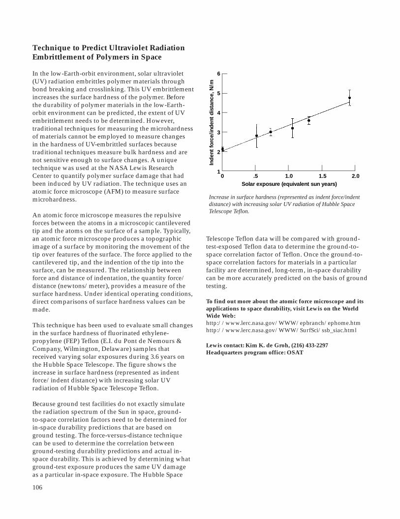
106
Technique to Predict Ultraviolet RadiationEmbrittlement of Polymers in Space
In the low-Earth-orbit environment, solar ultraviolet(UV) radiation embrittles polymer materials throughbond breaking and crosslinking. This UV embrittlementincreases the surface hardness of the polymer. Beforethe durability of polymer materials in the low-Earth-orbit environment can be predicted, the extent of UVembrittlement needs to be determined. However,traditional techniques for measuring the microhardnessof materials cannot be employed to measure changesin the hardness of UV-embrittled surfaces becausetraditional techniques measure bulk hardness and arenot sensitive enough to surface changes. A uniquetechnique was used at the NASA Lewis ResearchCenter to quantify polymer surface damage that hadbeen induced by UV radiation. The technique uses anatomic force microscope (AFM) to measure surfacemicrohardness.
An atomic force microscope measures the repulsiveforces between the atoms in a microscopic cantileveredtip and the atoms on the surface of a sample. Typically,an atomic force microscope produces a topographicimage of a surface by monitoring the movement of thetip over features of the surface. The force applied to thecantilevered tip, and the indention of the tip into thesurface, can be measured. The relationship betweenforce and distance of indentation, the quantity force/distance (newtons/meter), provides a measure of thesurface hardness. Under identical operating conditions,direct comparisons of surface hardness values can bemade.
This technique has been used to evaluate small changesin the surface hardness of fluorinated ethylene-propylene (FEP) Teflon (E.I. du Pont de Nemours &Company, Wilmington, Delaware) samples thatreceived varying solar exposures during 3.6 years onthe Hubble Space Telescope. The figure shows theincrease in surface hardness (represented as indentforce/indent distance) with increasing solar UVradiation of Hubble Space Telescope Teflon.
Because ground test facilities do not exactly simulatethe radiation spectrum of the Sun in space, ground-to-space correlation factors need to be determined forin-space durability predictions that are based onground testing. The force-versus-distance techniquecan be used to determine the correlation betweenground-testing durability predictions and actual in-space durability. This is achieved by determining whatground-test exposure produces the same UV damageas a particular in-space exposure. The Hubble Space
Telescope Teflon data will be compared with ground-test-exposed Teflon data to determine the ground-to-space correlation factor of Teflon. Once the ground-to-space correlation factors for materials in a particularfacility are determined, long-term, in-space durabilitycan be more accurately predicted on the basis of groundtesting.
To find out more about the atomic force microscope and itsapplications to space durability, visit Lewis on the WorldWide Web:http://www.lerc.nasa.gov/WWW/epbranch/ephome.htmhttp://www.lerc.nasa.gov/WWW/SurfSci/ssb_siac.html
Lewis contact: Kim K. de Groh, (216) 433-2297Headquarters program office: OSAT
0 1.5Solar exposure (equivalent sun years)
Ind
ent
forc
e/in
den
t d
ista
nce,
N/m
12.01.0.5
4
5
6
2
3
Increase in surface hardness (represented as indent force/indentdistance) with increasing solar UV radiation of Hubble SpaceTelescope Teflon.

107
Transparent, Conductive CoatingsDeveloped for Arc-Proof Solar Arrays
Transparent, conductive thin-film coatings have manypotential applications where a surface must be able todissipate electrical charges without sacrificing itsoptical properties. Such applications include automo-tive and aircraft windows, heat mirrors, optoelectronicdevices, gas sensors, and solar cell array surfaces forspace applications. Many spacecraft missions requirethat solar cell array surfaces dissipate charges in orderto avoid damage such as electronic upsets, formation ofpinholes in the protective coatings on solar arrayblankets, and contamination due to deposition ofsputtered products.
In tests at the NASA Lewis Research Center, mixedthin-films of sputter-deposited indium tin oxide (ITO)and magnesium fluoride (MgF2) that could be tailoredto the desired sheet resistivity showed transmittancevalues of greater than 90 percent. The samplesevaluated were composed of mixed, thin-film ITO/MgF2 coatings, with a nominal thickness of 650 Å,deposited onto glass substrates. Preliminary resultsindicated that these coatings were durable to vacuumultraviolet radiation and atomic oxygen. These coatingsshow promise for use on solar array surfaces in polarlow-Earth-orbit environments, where a sheet resistivityof less than 108 Ω/u is required, and in geosynchron-ous orbit environments, where a resistivity of less than109 Ω/u is required. The figures show electrical andoptical properties as a function of the estimated volumepercent of MgF2 in the mixed ITO/MgF2 coating.Future plans include demonstration of the coating’s
0.900.80
1.00
Tra
nsm
ittan
ceo
f sa
mp
le
0.70
0 20 30Calculated MgF2 content, vol %
10
108
1010
She
et r
esis
tanc
e o
ffil
m, V
/u
106
104
102
Transmittance (top) and sheet resistivity (bottom) of mixed ITO/MgF2 films as a function of the volume percent of MgF2.
durability to atomic oxygen and to vacuum ultravioletradiation.
Lewis contact: Joyce A. Dever, (216) 433-6294Headquarters program office: OSAT
Radiation Protection of New LightweightElectromagnetic Interference ShieldingMaterials Determined
Weight savings as high as 80 percent could be achievedby simply switching from aluminum electromagneticinterference (EMI) shielding covers for spacecraftpower systems to EMI covers made from intercalatedgraphite fiber composites. Because EMI covers typicallymake up about one-fifth of the power system mass, thischange would decrease the mass of a spacecraft powersystem by more than 15 percent.
Intercalated graphite fibers are made by diffusing guestatoms or molecules, such as bromine, between thecarbon planes of the graphite fibers. The resultingbromine-intercalated fibers have mechanical andthermal properties nearly identical to pristine graphitefibers, but their resistivity is lower by a factor of 5,giving them better electrical conductivity than stainlesssteel and making these composites suitable for EMIshielding.
EMI shields, however, must do more than just shieldagainst EMI. They must also protect electrical com-ponents from mechanical, thermal, and radiativedisturbances. Intercalated graphite fiber compositeshave a much higher specific strength than the alumi-num they would replace, so achieving sufficientmechanical strength and stiffness would not bedifficult. Also, the composites absorb and reradiateelectromagnetic radiation in the infrared region, so theyare actually considerably better at rejecting heat thanthe very reflective aluminum covers. What had notbeen characterized was how well these intercalatedgraphite fiber composites shielded components fromionizing radiation.
The shielding of high-energy radiation generallyincreases with the total number of electrons in an atom.Thus, carbon, which has 6 electrons per atom, is apoorer shield than aluminum, which has 13. Intercala-tion with a few percent of bromine (35 electrons/atom)or iodine (53 electrons/atom) was expected to improve
Aerospace Technology

108
the radiation shielding, though the average number ofelectrons per atom would still be below that ofaluminum. However, the results of tests done atManchester College, under a cooperative agreementwith the NASA Lewis Research Center, indicated asubstantial improvement in the radiation shielding—not only by a factor of 8 over the pristine graphitecomposite, but actually by a factor of 3 over aluminum.Intercalated graphite composites may well be the EMIcover of choice for spacecraft electronics operating in ahigh-radiation environment.
MASS ABSORPTION OF EMI MATERIALS
Material 46.5-keV 13.0-keV γ-ray, x-ray, cm2/g cm2/g
Aluminum 0.34 0.61 1.0 P-100 graphite .14 .25 .4 P-100 + Br2 .61 .96 1.7 P-100 + IBr 1.0 1.8 3.0
For more information about the work of Lewis’ Electro-Physics Branch, visit our site on the World Wide Web:http://www.lerc.nasa.gov/WWW/epbranch/ephome.htm
Lewis contact: James R. Gaier, (219) 982-5075 (Feb.-May andSept.-Dec.) and (216) 433-6686 (Jan. and June-Aug.)Headquarters program office: OSAT
mass abs mass abs Al
Silicone Contamination Camera Developedfor Shuttle Payloads
On many shuttle missions, silicone contamination fromunknown sources from within or external to the shuttlepayload bay has been a chronic problem plaguingexperiment payloads. There is currently a wide range ofsilicone usage on the shuttle. Silicones are used to coatthe shuttle tiles to enhance their ability to shed rain,and over 100 kg of RTV 560 silicone is used to sealwhite tiles to the shuttle surfaces. Silicones are alsoused in electronic components, potting compounds,and thermal control blankets. Efforts to date to identifyand eliminate the sources of silicone contaminationhave not been highly successful and have created muchcontroversy.
To identify the sources of silicone contamination onthe space shuttle, the NASA Lewis Research Centerdeveloped a contamination camera. This speciallydesigned pinhole camera utilizes low-Earth-orbitatomic oxygen to develop a picture that identifiessources of silicone contamination on shuttle-launchedpayloads.
The volatile silicone species travel through the apertureof the pinhole camera, and since volatile siliconespecies lose their hydrocarbon functionalities underatomic oxygen attack, the silicone adheres to thesubstrate as SiOx. This glassy deposit should bespatially arranged in the image of the sources ofsilicone contamination. To view the contaminationimage, one can use ultrasensitive thickness measure-ment techniques, such as scanning variable-angleellipsometry, to map the surface topography of thecamera’s substrate.
Ram atomic oxygen
RMS arm
Pinhole camera
Silicone contanimantsfrom source on shuttle
SiOx deposit
Silicone contamination camera for space shuttle payloads.

109
The demonstration of a functional contaminationcamera would resolve the controversial debateconcerning the amount and location of contaminationsources, would allow corrective actions to be taken, andwould demonstrate a useful tool for contaminationdocumentation on future shuttle payloads, with nearnegligible effect on cost and weight.
Lewis contacts: Bruce A. Banks, (216) 433-2308, andMark J. Forkapa, (216) 433-2299Headquarters program office: OSAT
In this reaction, a low rate of oxygen supply wouldcause the iron halide to evaporate before it could beconverted to iron oxide, resulting in low iron concen-tration in the carbon products. On the other hand,a high rate of oxygen supply would cause carbonremoval because of the formation of CO and CO2. Thecarbon removal would result in a high iron concentra-tion in structurally damaged carbon products. At anoptimum oxygen level, the iron halide in the carbonfibers would be converted to iron oxide or elementaliron without much halide evaporation or carbonstructural damage. Potential applications of the iron-containing carbon fibers and powder include spacecraftand aircraft electronic packaging as well as portable,personal-use communication equipment.
References
1. Hung, C.C.: Ferric Chloride-Graphite Intercalation Compounds Prepared From Graphite Fluoride. Carbon, vol. 33, no. 3, 1995, pp. 315-322.
2. Hung, C.C.: Fabrication of Iron-Containing Carbon Materials From Graphite Fluoride. Presented at the 22nd Biennial Conference on Carbon, University of California, San Diego, July 1995. American Carbon Society, pp. 656-657, 1995.
Lewis contact: Dr. Ching-Cheh Hung, (216) 433-2302Headquarters program office: OSAT
Iron-Containing Carbon MaterialsFabricated
Development of high-strength, lightweight materialsfor electromagnetic interference (EMI) shielding at lowfrequencies may be possible if the carbon fibers used inthese composites can be made to have ferromagneticproperties. One way to obtain such fibers is by insertingsmall ferromagnetic particles into the fiber structure.
Carbon fibers and carbon powder containing ironoxide, iron metal, or iron alloy have been successfullyfabricated at the NASA Lewis Research Center (refs. 1and 2). These carbon products can be attracted to aregular magnet. Typical samples were estimated tohave 1 iron atom per 3.5 to 5 carbon atoms. The sizesof the Fe3O4, iron metal, and iron alloy particles wereestimated to be in a wide 10- to 10,000-Å range.
In this fabrication process, first graphitefluoride (CFx) is exposed to FeCl3. Then theproduct is further heated in a low-oxygenenvironment, thereby depositing iron oxide,elemental iron, or iron alloy in or on the carbon.
Experiments were conducted to study thekinetics of the fabrication process (ref. 2). At 280to 295 °C, FeCl3 can quickly enter the structureof CFx; and in 10 to 30 min, it completelyconverts the CFx into carbon that has graphiteplanes between which crystalline FeF3 andnoncrystalline FeCl2 locate. Further heating thisproduct in a low-oxygen environment convertsthese iron halides into either a mixture of FeOand Fe3O4, if the temperature is in 750 to 850 °Crange, or into elemental iron, if the temperatureis at least 900 °C. During the final heat treat-ment at a temperature of 900 °C or higher,NiO or NiCl2 could be added to the reactionto produce a carbon material containing nickel-iron alloy, a ferromagnetic material.
Aerospace Technology
Iron-containing carbon materials on magnets.

110
Passive Optical Sample Assembly (POSA-2)Space Flight Experiment
NASA Lewis Research Center’s Electro-Physics Branchis participating in the POSA-2 Space Flight Experimentto assess the effects of low Earth orbit and spacecraftenvironment contamination on power system materialsand surfaces. This experiment package will be flown for1 year in low Earth orbit and will be returned to Earthfor subsequent evaluation of optical and thermalproperties. Representative samples of solar-arrayblanket materials, solar dynamic reflector materials,thermal control coatings, and sapphire are included inthe experiment package.
Thirty Lewis optical and thermal control coatingsamples were prepared, characterized, and integratedon the POSA-2 carrier. One-inch-diameter Kaptondisks, with and without a protective silicon dioxidecoating, were stamped out of stock material, dehy-drated, and weighed. Aluminum disks with aproprietary levelizing coating were coated by electron-beam evaporation with a reflective coating of eitheraluminum or silver and with a protective coating ofaluminum oxide and/or silicon dioxide.
In addition to mass measurements, total, diffuse, andspecular reflectivity values were obtained on thesesamples through the use of a Perkin-Elmer Lambda-9spectrophotometer equipped with a 150-mm-diameterintegrating sphere.
The optical properties of thermal control coatingsprovided by the Illinois Institute of TechnologyResearch Institute (IITRI) were evaluated in the visiblerange with an AZ Technology LPSR-200 reflectometerand in the infrared range with a Gier-Dunkle DB-100reflectometer. Sapphire contamination monitors alsowere prepared for flight. Each type of sample wasprepared in duplicate to accommodate the unusualopportunity to fly identical samples in both the ramand wake directions simultaneously. The samples wereintegrated in collaboration with the Boeing Space andDefense Group, Kent, Washington. Vibration testing isscheduled at the NASA Langley Research Center, andlaunch is expected in early 1996.
POSA-2 should provide important information on thedurability of materials to the low-Earth-orbit spaceenvironment in the near vicinity of spacecraft. It alsoshould provide information on potential contaminationand debris-related issues.
Find out more about the Electro-Physics Branch on theWorld Wide Web:http://www.lerc.nasa.gov/WWW/epbranch/ephome.htm
Lewis contact: Donald A. Jaworske, (216) 433-2312Headquarters program office: OSAT
Researchers installing samples in the POSA-2 flight experiment trays.

111
Aperture Shield Materials Characterizedand Selected for Solar Dynamic SpacePower System
The aperture shield in a solar dynamic space powersystem is necessary to prevent thermal damage to theheat receiver should the concentrated solar radiation beaccidentally or intentionally focused outside of the heatreceiver aperture opening and onto the aperture shielditself. Characterization of the optical and thermalproperties of candidate aperture shield materials wasneeded to support the joint U.S./Russian solar dynamicspace power effort for Mir.
The specific objective of testing performed at theNASA Lewis Research Center was to identify a high-temperature material with a low specular reflectance, alow solar absorptance, and a high spectral emittance sothat during an off-pointing event, the amount of solarenergy reflecting off the aperture shield would besmall, the α/ε ratio (ratio of solar absorptance to spec-tral emittance) would provide the lowest possibleequilibrium temperature, and the integrity of theaperture shield would remain intact.
An off-pointing event is defined as an event where thefocused light from the solar dynamic concentratormoves away from the aperture opening of the heatreceiver and onto the aperture shield itself. Such anevent would cause a considerable amount of solarenergy to impinge on a small area. This area, which isexpected to heat rapidly, must be made of a high-temperature material that can withstand temperaturesabove 2000 °C. The surface finish of thematerial must be diffuse so it does not reflectenergy back to the concentrator. Likewise, thesurface must have a low α/ε ratio to minimizeheating of the structure. Given the low-Earth-orbit application, the surface must also bedurable to atomic oxygen exposure.
Over 50 samples of high-temperaturematerials, including grit-blasted molybde-num, tungsten, and rhenium, were evaluatedin collaboration with AlliedSignal Inc. ofTorrance, California. Spectral reflectance wasobtained with a Perkin-Elmer Lambda-9spectrophotometer equipped with a 150-mm-diameter integrating sphere. Total and diffusereflectance were obtained from 250 to 2500and the data were convoluted into the airmass zero solar spectrum to obtain solarintegrated values. Specular reflectance wasobtained by subtraction. The solar absorp-tance was calculated by subtracting the
integrated solar total reflectance from unity. Emittancewas estimated from the spectral data with the use of acomputer program to integrate the reflectance data intoblackbody curves at elevated temperatures.
Only grit-blasted tungsten met all of the opticalrequirements for the off-pointing event on the apertureshield. Hence, selected samples of the grit-blastedtungsten were further exposed to a simulated atomicoxygen environment in a radiofrequency plasma asher,and to 2000 °C in a high-temperature vacuum furnace.Acceptable optical performance was observed afterboth of these exposures. As a result of the testing, grit-blasted tungsten foil combined with grit-blastedtungsten screen were identified as the materials ofchoice and were selected for constructing the apertureshield for the solar dynamic power system to beinstalled on space station Mir.
Find out more about the Mir Cooperative Solar ArrayProgram and the Joint U.S.-Russian Solar Dynamic FlightDemonstration on the World Wide Web:http://godzilla.lerc.nasa.gov/pspo/csa.htmlhttp://godzilla.lerc.nasa.gov/pspo/sddemo.html
Lewis contacts: Donald A. Jaworske, (216) 433-2312, andKim K. de Groh, (216) 433-2297Headquarters program office: OSAT
Aperture shield sample being installed in a UV-VIS-NIR (ultraviolet-visible-near infrared) spectrophotometer for optical properties evaluation.
Aerospace Technology
nm,

112
Atomic-Oxygen-Durable Microsheet GlassReflector
Advanced solar dynamic concentrator concepts beingconsidered by the NASA Lewis Research Center forspace power systems include one utilizing microsheetglass coated with silver. For this material, a 5000-Ålayer of silver is deposited on the back side of acontoured piece of microsheet glass, 0.2-mm thick. Thesilvered side is then bonded to a contoured aluminum,magnesium, or graphite epoxy face sheet with a space-qualified, pressure-sensitive thin-film adhesive.Experience gained from the development of thistechnology suggests that this material may reduce thecost and improve the performance of solar dynamicconcentrators. This microsheet glass technologyprovides an effective barrier to atomic oxygen attackand provides the opportunity to utilize silver-reflectivecoatings in low-Earth-orbit solar dynamic applications.
Forming the microsheet glass was found to be achallenge. A collaborative effort was initiated withexperts in the automotive industry, and a proprietaryforming process was developed. The microsheet glasscould be formed to the complex curved shapes neededfor solar dynamic concentrators, but the degree ofcurvature had to be gradual.
The second-surface silver mirror created by thistechnique is lightweight, durable, easily cleaned, andhas a total reflectivity of 94 percent. No debonding of
Environmental Influence of Gravity andPressure on Arc Tracking of InsulatedWires Investigated
Momentary short-circuit arcs between a defectivepolyimide-insulated wire and another conductor maythermally char (pyrolize) the insulating material. Thecharred polyimide, being conductive, can sustain theshort-circuit arc, which may propagate along the wirethrough continuous pyrolization of the polyimideinsulation (arc tracking). If the arcing wire is part of amultiple-wire bundle, the polyimide insulation of otherwires within the bundle may become thermally charredand start arc tracking also (flash over). Such arctracking can lead to complete failure of an entire wirebundle, causing other critical spacecraft or aircraftfailures.
Unfortunately, all tested candidate wire insulations foraerospace vehicles were susceptible to arc tracking.Therefore, a test procedure was designed at the NASALewis Research Center to select the insulation type leastsusceptible to arc tracking. This test procedure addres-ses the following three areas of concern: (1) probabilityof initiation, (2) probability of reinitiation (restrike), and(3) extent of arc tracking damage (propagation rate).Item 2 (restrike probability) is an issue if power can beterminated from and reapplied to the arcing wire (by aswitch, fuse, or resettable circuit breaker). The degree ofdamage from an arcing event (item 3) refers to how
the microsheet glass composite structure was indicatedafter vacuum exposure and thermal cycling between-80 and 80 °C, and after atomic oxygen exposure, onlyminor deterioration of the reflective surface, limited toregions near the edges and seams was evident. Theoverall mass per unit area was 2.5 kg/m2.
This technology enables the use of silver as a reflectivecoating in the low-Earth-orbit atomic oxygen environ-ment. Using silver, rather than other materials, as areflector will increase the overall efficiency of proposedsolar dynamic power systems.
Lewis contact: Donald A. Jaworske, (216) 433-2312Headquarters program office: OSAT
Reflected image in a microsheet glass reflector bonded to a graphiteepoxy composite face sheet.

113
Experimental Results From the ThermalEnergy Storage-1 (TES-1) Flight Experiment
The Thermal Energy Storage (TES) experiments aredesigned to provide data to help researchers under-stand the long-duration microgravity behavior ofthermal energy storage fluoride salts that undergorepeated melting and freezing. Such data, which havenever been obtained before, have direct application tospace-based solar dynamic power systems. Thesepower systems will store solar energy in a thermalenergy salt, such as lithium fluoride (LiF) or a eutecticof lithium fluoride/calcium difluoride (LiF-CaF2)(which melts at a lower temperature). The energy willbe stored as the latent heat of fusion when the salt ismelted by absorbing solar thermal energy. The storedenergy will then be extracted during the shade portionof the orbit, enabling the solar dynamic power systemto provide constant electrical power over the entireorbit.
Analytical computer codes have been developed topredict the performance of a space-based solar dynamicpower system. However, the analytical predictionsmust be verified experimentally before the analyticalresults can be used for future space power designapplications. Four TES flight experiments will be usedto obtain the needed experimental data. This articlefocuses on the flight results from the first experiment,TES-1, in comparison to the predicted results from theThermal Energy Storage Simulation (TESSIM)analytical computer code.
Developed by Dr. David Jacqmin of the NASA LewisResearch Center’s Internal Fluid Mechanics Division,TESSIM can predict the migration of voids and theresulting thermal behavior of solar dynamic receivercanisters. It is currently useful as a qualitative designtool but requires further experimental validation beforeit can be reliably used for critical design decisions. Oncethoroughly validated, the code will be invaluable in thedetailed design of lighter, more efficient solar dynamicreceivers.
An advanced solar dynamic power system with either aBrayton or Stirling Power Conversion System has thepotential for high efficiency with lower weight, cost,and area than other solar power systems. Whenoperating in a low Earth orbit, the power system willexperience a sun/shade cycle on the order of 60-minsun and 34-min shade. Delivery of continuous electricpower over the entire orbit requires a method of storingenergy during the sun cycle for use during the shadecycle.
Aerospace Technology
Comparison of MIL-W-81381 insulated wire (20 AWG), in eachenvironment of interest, with respect to the distance the arc travelsin 16 sec.
easily the arc chars nearby insulation and propagatesalong the wire pair. Ease of nearby insulation charringcan be determined by measuring the rate of arcpropagation. Insulation that chars easily will propagatethe arc faster than insulation that does not char veryeasily.
A popular polyimide insulated wire for aerospacevehicles, MIL-W-81381, was tested to determine adegree of damage from an arcing event (item 3) in thefollowing three environments: (1) microgravity (µg)with air at 1-atm pressure, (2) 1g with air at 1 atm, and(3) 1g within a 10-6 Torr vacuum.
The microgravity 1-atm air was the harshest envi-ronment, with respect to the rate of damage of arctracking, for the 20 AWG (American Wiring Gauge)MIL-W-81381 wire insulation type . The vacuumenvironment resulted in the least damage. Furthertesting is planned to determine if the environmentalresults are consistent between insulation types and toevaluate the other two parameters associated with arctracking susceptibility.
Lewis contact: Thomas J. Stueber, (216) 433-2218(E-Mail: [email protected])Headquarters program office: OSMA
Dis
tanc
e tr
avel
ed, i
n.
0.20
0.15
0.10
0.05
0.0078 124 111
Force,g011
Pressure
1 atm1 atm
10-6 Torr
Size
vacuum
0.11420.091
0.0168

114
salt melting and freezing under microgravity, do notabsolutely validate TESSIM, but the comparison of thepredictions with the data establishes a basic confidencein the code. Future experiments, such as TES-2, -3, and-4 will help to further validate TESSIM.
The TES-1 flight experiment provided the first experi-mental data on the long-duration effects on TES saltsused for space-based solar dynamic power systems.Good correlation between the predicted on-orbitcharacteristics of the salt and the actual flight data indi-cate that, for the configuration tested, the TESSIM codeis basically sound. The additional three flight experi-ments will provide the opportunity for the TESSIMcode to be validated completely. The flight experimentswill provide data from different canister configurationsand both wetting and nonwetting interfaces for the TESsalts. In addition, the effect of heat leakage will bestudied more closely.
Find out more about TES on the World Wide Web:http://powerweb.lerc.nasa.gov/soldyn/DOC/TESp.html
Lewis contacts: Carol M. Tolbert, (216) 433-6167; LawrenceW. Wald, (216) 433-5219; and Dr. David A. Jacqmin,(216) 433-5853Headquarters program office: OSAT
An efficient method of accomplishing this is to utilizethe high heat-of-fusion associated with TES phase-change materials. These materials possess physicalproperties that are desirable in advanced solar dynamicheat receiver designs—including high heat-of-fusion,very low toxicity, and general compatibility withcontainment materials in a vacuum environment.However, they also have low thermal conductivity, lowdensity, and most significantly, high specific-volumechange with phase change. This last characteristic leadsto the formation of a void, or voids, that can degradeheat-receiver energy transfer performance by forminglocal hot spots on the container wall or by distorting thewall locally. Because the formation and location ofvoids are strongly influenced by gravitational forces, itis necessary to be able to understand and predict thisphenomenon in the on-orbit microgravity environmentin order to achieve the optimum design for the heatreceiver canisters. This is especially important since thecanister and heat receiver are significant elements of theoverall weight and cost of a solar dynamic powersystem.
Four experiments are needed to provide the datanecessary to validate the TESSIM code. The first twoflight experiments, TES-1 and TES-2, were developed toobtain data on TES material behavior in cylindricalcanisters. These experiments are identical except for thefluoride salts characterized. TES-1 used lithium fluoride(LiF) salt, which melts at 1121 K; and TES-2 will use afluoride eutectic salt (LiF/CaF2), which melts at 1042 K.A postflight tomographic scan of each TES canister willprovide data on void location, size, and distribution forcomparison with TESSIM predictions.
From the data collected on orbit, the first figure showssome erratic behavior in the first melt cycle in com-parison to the remaining three melt-freeze cycles. Webelieved this to be caused by migration of the voidand/or by the gravitational forces present during thisperiod. In general, after the first melt-freeze cycle, thetemperatures show repeatability from cycle to cycle ateach location.
After the experiment, the canister was scanned byComputer-Aided Tomography (CAT) to record the finallocation and distribution of the voids in the canister.The second figure (ref. 1) shows the tomographic datataken on the TES-1 canister for nine stations along thelength of the canister, along with the predicted resultsfrom TESSIM. Salt locations are shown in black. Ingeneral, TESSIM appears to have predicted voidbehavior accurately, as is evidenced by comparing thetomographic images with the TESSIM images. Theseinitial results from TES-1, of high-temperature fluoride
2-kW Solar Dynamic Space Power SystemTested in Lewis' Thermal Vacuum Facility
Working together, a NASA/industry team successfullyoperated and tested a complete solar dynamic spacepower system in a large thermal vacuum facility with asimulated sun. This NASA Lewis Research Centerfacility, known as Tank 6 in building 301, accuratelysimulates the temperatures, high vacuum, and solarflux encountered in low-Earth orbit. The solar dynamicspace power system shown in the first figure in theLewis facility, includes the solar concentrator and thesolar receiver with thermal energy storage integratedwith the power conversion unit. Initial testing inDecember 1994 resulted in the world’s first operationof an integrated solar dynamic system in a relevantenvironment.
Acceptance testing of the solar dynamic system wasaccomplished in only 3 months, from December 1994through February 1995, by an industry team led byAlliedSignal Inc. with support from Lewis. Over 2 kWof electrical power was produced on February 17, 1995,while the system was operating at 52,000 rpm with aturbine inlet temperature of 1063.5 K (790.5 °C) and a

115
1.14 Sun
0 35 450
40
1600
105
800
1200
1000
1400
1800
600
400
200
Tem
per
atur
e, R
, or
po
wer
, W
15 20 25 30Time, hr
4 8 15 21
1.06 Sun 1.08 SunInsolation level
Balancedorbits
Receiver cavity temperatureTurbine-inlet temperaturedc powerCompressor-inlet temperature
2000
1.01 Sun
1
Aerospace Technology
compressor inlet temperature of 270.2 K (-2.8 °C).AlliedSignal’s acceptance testing involved about 40 hrof power operation with 10 orbits, including 5 suc-cessful ambient starts with 1 hot restart. Operation ofthe turboalternator-compressor was shown to be withinacceptable limits. The 2-kW solar dynamic system wasturned over to NASA in March 1995.
The solar dynamic system was tested for over 365 hrof power operation, ranging from 300 W to 2.0 kW,including 187 simulated low-Earth orbits, 16 ambientstarts, and 2 hot restarts. NASA characterized the solardynamic system and evaluated various analyticalmodels over a variety of solar insolation levels, speedconditions, orbit periods, and engine inventoriesto support the joint U.S./Russian 2-kW SolarDynamic Flight Demonstration project. Systemtesting showed that an overall system efficiency(conversion of sun into user energy) was in excessof 15 percent, whereas the engine cycle efficiencywas over 26 percent. Foil bearing technologies,developed in the 1970’s, were successfully demon-strated with 48 start/stops on the turboalternator-compressor. Finally, the solar dynamic space powersystem demonstrated orbital startup, transient andsteady-state orbital operation, and shutdown in arelevant space environment.
The graph shows an example of data from anoperational solar dynamic system (receiver andpower conversion unit), including the averagereceiver cavity temperature, the turbine-inlettemperature, the compressor-inlet temperature,and the dc power output. This test was conductedover a 40-hr period with the turboalternator-compressor operating at 48,000 rpm. It illustratesan orbital startup, transient and steady-state orbitaloperation, and a shutdown. The turboalternator-compressor was operating at 48,000 rpm through-out the test, except for the shutdown at 52,000 rpm.The solar simulator provided four differentinsolation levels—1.01, 1.06, 1.08, and 1.14 suns(1.37 kW/m2 = 1 sun)—resulting in four steady-state orbital cases during the 93-min orbit.Balanced orbital operation was achieved on orbits4, 8, 15, and 21. The first three cases are in asensible heat receiver (where the canister phase-change material does not melt), which resulted inlarge temperature (137.2 K) and power (138 W)fluctuations. The fourth case, a latent heat receiverstate, resulted in a marked reduction of tempera-ture (19.4 K) and power (49 W) fluctuations duringthe orbit, which are in good agreement withanalytical predictions. For this off-design point,overall “system” efficiency (conversion of sun into
user energy) was in excess of 14 percent and theengine efficiency was about 24 percent.
The collective efforts of the NASA/industry teamresulted in the first full-scale demonstration of acomplete space-configured solar dynamic system in alarge thermal vacuum facility with a simulated sun.Initial operational and performance data havedemonstrated a solar dynamic power system withsufficient scale and fidelity to ensure confidence in theavailability of solar dynamic technology for space.Studies have shown that solar dynamic power withthermal energy storage can provide continuous electricpower in near-Earth orbits with significant savings inlife-cycle costs and launch mass when compared with
Top: Data showing startup, multiple orbits, and shutdown ofsolar dynamic system. Bottom: Solar dynamic system installed intank 6.

116
USA Digital FM-1 MUSICAM 256 1IBOC 88 to 108USA Digital FM-2 MUSICAM 256 1IBOC 88 to 108AT&T/AMATILSB 2PAC 128 1IBOC 88 to 108AT&T/AMATILSB 2PAC 160 1IBOC 88 to 108USA Digital AM MUSICAM 92 1IBOC 525 to 1705AT&T 2PAC 160 3IBAC 88 to 108EUREKA 147 MUSICAM 224 New band 1452 to 1492EUREKA 147 MUSICAM 192 New band 1452 to 1492VOA/JPL 2PAC 160 4DBS 2310 to 2360
compact-disc-quality (CD-quality) sound for the firsttime.
Lewis is hosting the laboratory testing of sevenproposed digital audio radio systems and modes (seethe table). Two of the proposed systems operate in twomodes each, making a total of nine systems beingtested. The nine systems are divided into the followingtypes of transmission: in-band on-channel (IBOC),in-band adjacent-channel (IBAC), and new bands. Thelaboratory testing was conducted by the ConsumerElectronics Group of the Electronic IndustriesAssociation. Subjective assessments of the audiorecordings for each of the nine systems was conductedby the Communications Research Center in Ottawa,Canada, under contract to the Electronic IndustriesAssociation. The Communications Research Center hasthe only CCIR-qualified (Consultative Committee forInternational Radio) audio testing facility in NorthAmerica.
DESCRIPTIONS OF LABORATORY-TESTED SYSTEMS
1 In-band on-channel.2 The AT&T-developed source-coding scheme called Perceptual Audio Coding (PAC) is derived from the notion of distortion-masking in the human auditory system, the phenomenon whereby one signal can completely mask a suffi- ciently weaker signal in its frequency or time vicinity.3 In-band adjacent channel.4 Direct Broadcast Satellite.
Proponents delivered their proposed systems to Lewisin January and February of 1994. Laboratory testingbegan in March 1994 and concluded in June 1995.Following the laboratory testing, the systems will beinstalled in a van for field testing in San Francisco,California.
The main goals of the U.S. testing process are to(1) provide technical data to the Federal Communi-cation Commission (FCC) so that it can establish astandard for digital audio receivers and transmittersand (2) provide the receiver and transmitter industrieswith the proper standards upon which to build theirequipment. In addition, the data will be forwarded to
Digital Audio Radio Broadcast SystemsLaboratory Testing Nearly Complete
Radio history continues to be made at the NASA LewisResearch Center with the completion of phase one ofthe digital audio radio (DAR) testing conducted bythe Consumer Electronics Group of the ElectronicIndustries Association. This satellite, satellite/terrestrial, and terrestrial digital technology willopen up new audio broadcasting opportunities bothdomestically and worldwide. It will significantlyimprove the current quality of amplitude-modulated/frequency-modulated (AM/FM) radio with a newdigitally modulated radio signal and will introduce true
conventional photovoltaic power systems with batterystorage for providing continuous electric power innear-Earth orbits. Testing has demonstrated that thesolar dynamic technologies developed by NASAprograms during the past 30 years are available fornear-Earth orbit applications. Applications includepotential growth for the international space station, forcommunication and Earth-observing satellites, and forelectric propulsion.
An aerospace Government/industry team workedtogether to successfully demonstrate solar dynamicpower for space in a way that was “cheaper, faster, andbetter.” The solar dynamic ground test demonstrationprogram was completed in early 1995, ahead of sched-ule and under budget. The Government/industry teamdelivered the 2-kW solar dynamic system demonstra-tion as promised.
Bibliography
Shaltens, R.K.; and Boyle, R.V.: Update of the 2 kW SolarDynamic Ground Test Demonstration Program. NASATM-106730, 1994.
Shaltens, R.K.; and Boyle, R.V.: Initial Results From the SolarDynamic (SD) Ground Test Demonstration (GTD) Project atNASA Lewis. NASA TM-107004, 1995.
To find out more about the 2-kW Solar Dynamic SpacePower System, visit our site on the World Wide Web:http://powerweb.lerc.nasa.gov/soldyn/DOC/SDGTD.html
Lewis contact: Richard K. Shaltens, (216) 433-6138Headquarters program office: OA
Space Electronics
System Source Data rate System Proposed band, coding tested, type MHz
kbs

117
the International Telecommunications Union to help inthe establishment of international standards for digitalaudio receivers and transmitters, thus allowing U.S.manufacturers to compete in the world market.
The overall testing procedures were developed by theElectronics Industries Association in cooperation withthe National Radio Standards Committee, all systemproponents, equipment manufacturers, and otherinterested parties. The basic goals of the laboratory testswere to determine the digital audio quality producedby each system, the reception reliability, the ability tocoexist with other receivers and broadcast stations(including, in the case of in-band on-channel, the hostanalog station), and the repeatability of all tests. Systemtesting was conducted with digital audio radioencoders and receivers supplied by the proponents.Other test gear was either provided by interested thirdparties or purchased by the Electronics IndustriesAssociation.
The laboratory tests conducted at Lewis were done intwo phases: digital and in-band compatibility. Sometests were conducted on all systems, and others weredesigned for specific system types. The digital tests(conducted on all systems) included evaluation ofquality and characterization of signal failure and ofmultipath, co-channel, and adjacent channel impair-ments. The in-band tests (conducted on specificsystems) included tests to measure possible interfer-ence to the existing analog transmission caused by theintroduction of in-band digital audio radio. Tests alsowere conducted to assess the compatibility of theanalog and digital ancillary service channels with thein-band on-channel and in-band adjacent channelsignals.
Onsite testing specialists conducted threshold-of-audibility and point-of-failure tests at Lewis. Results ofall transmission tests were digitally recorded on digitalaudio tapes and sent to the Communications ResearchCenter for assessment by listening specialists.
Laboratory test results were announced by theElectronics Industry Association on September 24, 1995,in Monterey, California. Their Digital Audio RadioSubcommittee indicated that these results by them-selves reflect only half of the picture. The second halfof the picture will come from the field testing to beconducted in San Francisco, California. These tests,which are equally critical, will determine how well eachproponent’s system will perform under real-world,uncontrollable conditions.
Role of Communications Satellites in theNational and Global InformationInfrastructure
Early in 1995, the Satellite Industry Task Force (SITF)was initiated by executives of the satellite industry todefine the role for communication satellites in theNational and Global Information Infrastructure (NII/GII). Satellites are essential to this information networkbecause they offer ubiquitous coverage and less time tomarket. SITF, which was chaired by Dr. ThomasBrackey of the Hughes Space and CommunicationDivision, grew out of a series of workshops held duringthe summer of 1994 by the communication industry,NASA, and the Defense Information Systems Agency(DISA). Experts were convened from 20 companiesrepresenting satellite and terrestrial network builders,operators, and users. For 8 months they worked toidentify challenges for the satellite industry to play apivotal role in the National and Global InformationInfrastructure. NASA Lewis Research Center personnelhelped out with technical and policy matters.
After collecting significant amounts of data andanalysis on various issues, SITF participants reached aconsensus on five key challenges. Three of the chal-lenges are policy related: access to the communicationssector of the electromagnetic spectrum, trade andsecurity, and access to markets. The remaining two aretechnical: seamless interoperability and technologyadvancement. SITF also recommended various actionsto be taken by the U.S. Government and industry tomeet these challenges.
SITF findings were presented to U.S. Vice PresidentAl Gore during the Office of Science and TechnologyPolicy’s White House Forum on September 12, 1995, aspart of the U.S. Government’s efforts to promote theNational and Global Information Infrastructure. Thismeeting was attended by NASA Administrator DanielGoldin and by senior representatives from the Federal
Aerospace Technology
The field test data plus the laboratory test data willcomplete the testing process for establishing standards.The United States will be able to establish realisticdomestic digital audio radio standards based on harddata. The United States will also be a key player inestablishing future international digital audio radioservice standards.
Lewis contact: James E. Hollansworth, (216) 433-3458Headquarters program office: OSAT
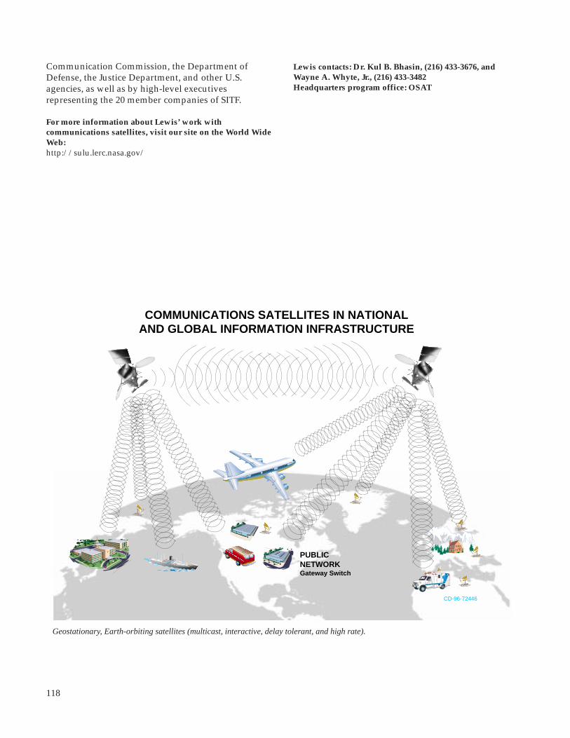
118
Communication Commission, the Department ofDefense, the Justice Department, and other U.S.agencies, as well as by high-level executivesrepresenting the 20 member companies of SITF.
For more information about Lewis’ work withcommunications satellites, visit our site on the World WideWeb:http://sulu.lerc.nasa.gov/
Geostationary, Earth-orbiting satellites (multicast, interactive, delay tolerant, and high rate).
Gateway Switch
PUBLICNETWORK
COMMUNICATIONS SATELLITES IN NATIONALAND GLOBAL INFORMATION INFRASTRUCTURE
CD-96-72446
ACTS
ACTS
ACTS
URBAN
GENERAL
HOSPITAL
Lewis contacts: Dr. Kul B. Bhasin, (216) 433-3676, andWayne A. Whyte, Jr., (216) 433-3482Headquarters program office: OSAT

119
Lewis Helps Examine Feasibility of FixedSatellite Service and Local MultipointDistribution Service Sharing the SameFrequency Band
The Federal Communications Commission (FCC) is inthe midst of a rule-making procedure that may have afar-reaching effect on the future of Ka-band satelliteservices. In December 1992, the FCC issued a Notice ofProposed Rule Making that proposed redesignating the27.5- to 29.5-GHz band (referred to as the 28-GHz band)from fixed, point-to-point services to a new localmultipoint distribution service (LMDS).
LMDS is a proposed terrestrial wireless communicationservice primarily directed at video distribution oversmall cells. LMDS proponents anticipate that the ser-vice would provide cost-effective competition to cabletelevision systems in urban areas.
The 27.5- to 29.5-GHz band also is allocated bothdomestically and internationally on a primary basisto the Fixed Satellite Service (FSS), and it is currentlybeing used by the NASA Lewis Research Center’sAdvanced Communications Technology Satellite(ACTS) for uplink transmissions. Seventeen U.S.companies have now filed for commercial satellitecommunications systems that would utilize the bandfor uplink and/or feeder link operations.
At the time that the FCC released the Notice ofProposed Rule Making on LMDS for comment, thesatellite industry was embroiled in the Mobile SatelliteService (MSS) Above 1 GHz Negotiated Rule Making.NASA responded to the Notice of Proposed RuleMaking and filed the first discussion regarding thepotential for interference between Fixed SatelliteService and LMDS services. (Thefigure depicts interference pathsbetween these two services.)NASA sensitized the satellitecommunity to the LMDS issueswhich resulted in further industryopposition to the FCC proposal,citing the inability for futuresatellite systems to share the28-GHz band on a cofrequencybasis with proposed LMDSsystems.
In July 1994, the FCC convened aNegotiated Rule-MakingCommittee to attempt to resolvethe interference issues and Interference scenario between Local Multipoint Distribution Service and Fixed Satellite Service.
Aerospace Technology
Ka-band satellitetransmission
LMDS—satellite interferenceat Ka-band
LMDS Ka-bandtelevision transmission
identify rules that would allow frequency cosharingbetween Fixed Satellite Service and LMDS services.Twenty-five companies and organizations, includingNASA, participated in the committee, which repre-sented both satellite and LMDS concerns. Lewis’ SpaceElectronics Division personnel made significant ana-lytical and experimental contributions to the work ofthe committee.
Despite 60 days of concerted effort by the committee,no sharing solution was found. The primary inter-ference issue centers around the inability to collocateFixed Satellite Service uplink terminals within reason-able separation distances from LMDS subscriberreceivers, and the proposed ubiquitous deployment ofFixed Satellite Service terminals and LMDS receiverswithin the same service areas.
In an effort to reach a compromise solution that wouldallow both satellite and LMDS services in the band, theFCC now appears ready to propose segmenting theband. Several segmentation proposals have been filedwith the FCC from both satellite and LMDS propo-nents. These proposals generally satisfy the minimumspectrum requirements of all interests who have filed todate with the FCC for LMDS and satellite systems. Thelong-term consequences of such a compromise, how-ever, may have a far-reaching and lasting effect on thesatellite industry and the future services that it canoffer. Limiting the primary spectrum available forsatellite services in the 27.5- to 29.5-GHz band willpotentially impede the growth of the satellite industry,
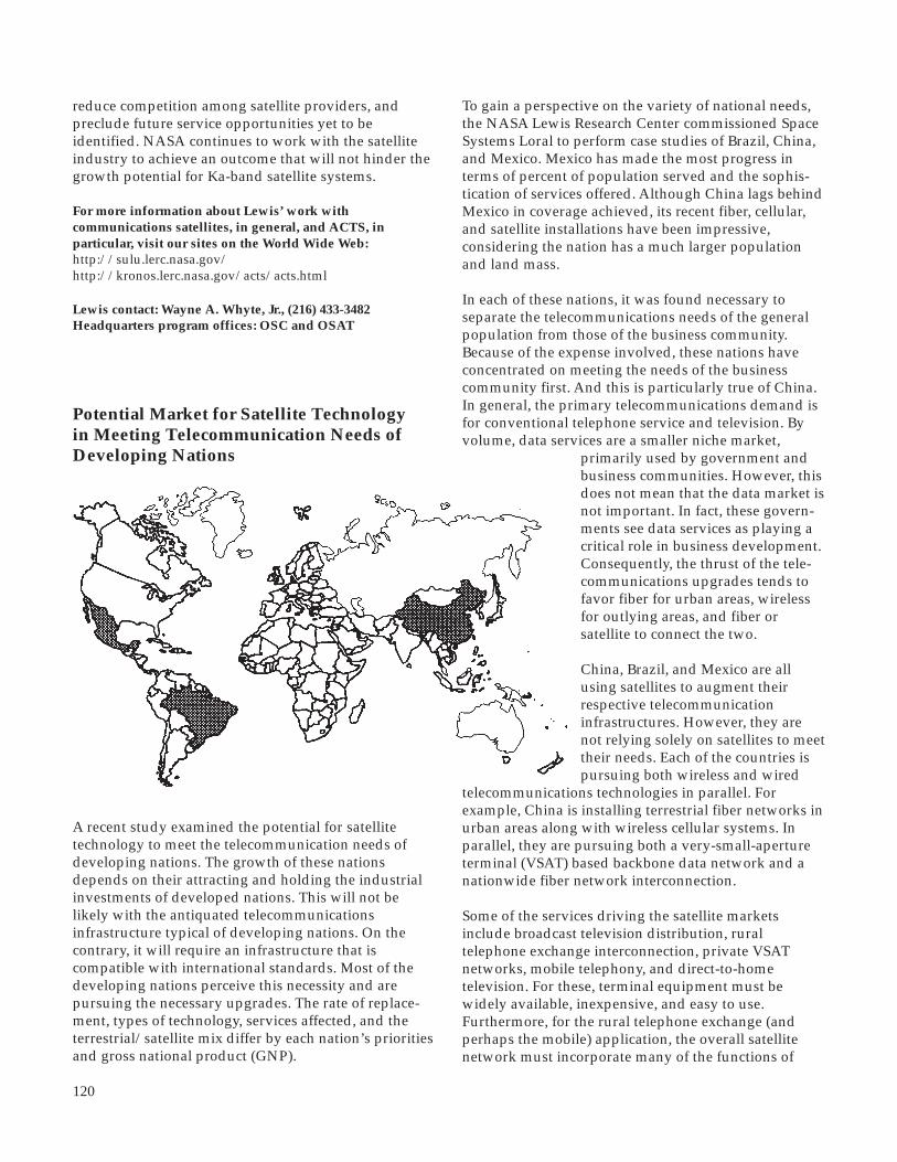
120
reduce competition among satellite providers, andpreclude future service opportunities yet to beidentified. NASA continues to work with the satelliteindustry to achieve an outcome that will not hinder thegrowth potential for Ka-band satellite systems.
For more information about Lewis’ work withcommunications satellites, in general, and ACTS, inparticular, visit our sites on the World Wide Web:http://sulu.lerc.nasa.gov/http://kronos.lerc.nasa.gov/acts/acts.html
Lewis contact: Wayne A. Whyte, Jr., (216) 433-3482Headquarters program offices: OSC and OSAT
Potential Market for Satellite Technologyin Meeting Telecommunication Needs ofDeveloping Nations
A recent study examined the potential for satellitetechnology to meet the telecommunication needs ofdeveloping nations. The growth of these nationsdepends on their attracting and holding the industrialinvestments of developed nations. This will not belikely with the antiquated telecommunicationsinfrastructure typical of developing nations. On thecontrary, it will require an infrastructure that iscompatible with international standards. Most of thedeveloping nations perceive this necessity and arepursuing the necessary upgrades. The rate of replace-ment, types of technology, services affected, and theterrestrial/satellite mix differ by each nation’s prioritiesand gross national product (GNP).
To gain a perspective on the variety of national needs,the NASA Lewis Research Center commissioned SpaceSystems Loral to perform case studies of Brazil, China,and Mexico. Mexico has made the most progress interms of percent of population served and the sophis-tication of services offered. Although China lags behindMexico in coverage achieved, its recent fiber, cellular,and satellite installations have been impressive,considering the nation has a much larger populationand land mass.
In each of these nations, it was found necessary toseparate the telecommunications needs of the generalpopulation from those of the business community.Because of the expense involved, these nations haveconcentrated on meeting the needs of the businesscommunity first. And this is particularly true of China.In general, the primary telecommunications demand isfor conventional telephone service and television. Byvolume, data services are a smaller niche market,
primarily used by government andbusiness communities. However, thisdoes not mean that the data market isnot important. In fact, these govern-ments see data services as playing acritical role in business development.Consequently, the thrust of the tele-communications upgrades tends tofavor fiber for urban areas, wirelessfor outlying areas, and fiber orsatellite to connect the two.
China, Brazil, and Mexico are allusing satellites to augment theirrespective telecommunicationinfrastructures. However, they arenot relying solely on satellites to meettheir needs. Each of the countries ispursuing both wireless and wired
telecommunications technologies in parallel. Forexample, China is installing terrestrial fiber networks inurban areas along with wireless cellular systems. Inparallel, they are pursuing both a very-small-apertureterminal (VSAT) based backbone data network and anationwide fiber network interconnection.
Some of the services driving the satellite marketsinclude broadcast television distribution, ruraltelephone exchange interconnection, private VSATnetworks, mobile telephony, and direct-to-hometelevision. For these, terminal equipment must bewidely available, inexpensive, and easy to use.Furthermore, for the rural telephone exchange (andperhaps the mobile) application, the overall satellitenetwork must incorporate many of the functions of
121
the terrestrial telephone system, namely switching,routing, and access control.
Bibliography
Barker, K.; Barnes, C.; and Price, K.M.: Space-BasedCommunications Infrastructure for DevelopingCountries. NASA CR-198371, 1995.
For more information about Lewis’ work withcommunications satellites, visit our site on the World WideWeb:http://sulu.lerc.nasa.gov/
Lewis contact: Grady H. Stevens, (216) 433-3463 (E-Mail:[email protected])Headquarters program office: OSAT
may arise in the system bias-distribution network. Byplacing the devices in a series bias configuration, thetotal current is reduced, leading to reduced distributionlosses. Careful design of the on-chip planar outputstage power combiner is also important in minimizinglosses. Using these concepts, a two-stage amplifier wasdesigned for operation at 33 GHz and fabricated in astandard MMIC foundry process with 0.20-µm PHEMTdevices. Using a 20-V bias supply, the amplifierachieved efficiencies of over 40 percent with an outputpower of 0.66 W and a 16-dB gain over a 2-GHzbandwidth centered at 33 GHz. With a 28-V bias, apower level of 1.1 W was achieved with a 12-dB gainand a 36-percent efficiency (ref. 1). This represents thebest reported combination of power and efficiency atthis frequency.
In addition to delivering excellent power and gain, thisKa-band MMIC power amplifier has an efficiency thatis 10 percent greater than existing designs. The uniquedesign offers an excellent match for spacecraft appli-cations since the amplifier supply voltage is closelymatched to the typical value of spacecraft bus voltage.These amplifiers may be used alone in applications of1 W or less, or several may be combined or used in anarray to produce moderate power, Ka-band trans-mitters with minimal power combining and lessthermal stress owing to the combination of excellentefficiency and power output. The higher voltageoperation of this design may also save mass and powerbecause the dc-dc power converter is replaced with asimpler voltage regulator.
Reference
1. Schellenberg, J.M.: A High-Voltage, Ka-Band Power MMIC With 41% Efficiency. Technical Digest 1995. Proceedings of the 17th Annual GaAs IC Symposium, 95CH35851, Oct. 29 - Nov. 1, 1995, pp. 284-287.
To find out more about Lewis’ work with communicationssatellites, visit our site on the World Wide Web:http://sulu.lerc.nasa.gov/
Lewis contact: Dr. Edward J. Haugland, (216) 433-3516(E-Mail: [email protected])Headquarters program office: OSAT
Highly Efficient Amplifier for Ka-BandCommunications
An amplifier developed under a Small BusinessInnovation Research (SBIR) contract will have appli-cations for both satellite and terrestrial communica-tions. This power amplifier uses an innovative seriesbias arrangement of active devices to achieve over40-percent efficiency at Ka-band frequencies with anoutput power of 0.66 W. The amplifier is fabricated ona 2.0- by 3.8-mm2 chip through the use of MonolithicMicrowave Integrated Circuit (MMIC) technology, andit uses state-of-the-art, Pseudomorphic High-Electron-Mobility Transistor (PHEMT) devices.
Although the performance of the MMIC chip dependson these high-performance devices, the real innovationshere are a unique series bias scheme, which results in ahigh-voltage chip supply, and careful design of the on-chip planar output stage combiner. This design concepthas ramifications beyond the chip itself because itopens up the possibility of operation directly from asatellite power bus (usually 28 V) without a dc-dcconverter. This will dramatically increase the overallsystem efficiency.
Conventional microwave power amplifier designsutilize many devices all connected in parallel from thebias supply. This results in a low-bias voltage, typically5 V, and a high-bias current. With this configuration,substantial I2R losses (current squared times resistance)
Aerospace Technology

122
Chemical Vapor-Deposited (CVD) DiamondFilms for Electronic Applications
Diamond films have a variety of useful applicationsas electron emitters in devices such as magnetrons,electron multipliers, displays, and sensors. Secondaryelectron emission is the effect in which electrons areemitted from the near surface of a material because ofenergetic incident electrons. The total secondary yieldcoefficient σ, which is the ratio of the number of secon-dary electrons to the number of incident electrons,generally ranges from 2 to 4 for most materials used insuch applications. It was discovered recently at theNASA Lewis Research Center that chemical vapor-deposited (CVD) diamond films have very highsecondary electron yields, particularly when they arecoated with thin layers of CsI. For CsI-coated diamondfilms, the value of σ can exceed 60.
Also, diamond films exhibit field emission at fieldsthat are orders of magnitude lower than for existingstate-of- the-art emitters. Present state-of-the-artmicrofabricated field emitters generally require appliedfields above 5x10⁷ V/cm. Research on field emissionfrom CVD diamond and high-pressure, high-temper-ature diamond has shown that field emission can beobtained at fields as low as 2x10⁴ V/cm. It has alsobeen shown that thin layers of metals, such as gold, andof alkali halides, such as CsI, can significantly increasefield emission and stability. Emitters with nanometer-scale lithography will be able to obtain high-currentdensities with voltages on the order of only 10 to 15 V.
Bibliography
Mearini, G.T., et al.: Fabrication of an Electron MultiplierUtilizing Diamond Films. Thin Sol. Fil., vol. 253, 1994,pp. 151-156.
Mearini, G.T.; Krainsky, I.L.; and Dayton, J.A., Jr.,:Investigation of Diamond Films for Electronic Devices.Surf. and Interface Anal., vol. 21, 1994, pp. 138-143.
Mearini, G.T., et al.: Stable Secondary Electron EmissionObservations From Chemical Vapor Deposited Diamond.Appl. Phys. Lett., vol. 65, no. 21, Nov. 1994, pp. 2702-2704.
Mearini, G.T., et al.: Stable Secondary Electron EmissionFrom Chemical Vapor Deposited Diamond Films CoatedWith Alkali-Halides. Appl. Phys. Lett., vol. 66, no. 2, Jan.1995, pp. 242-244.
Lamouri, A., et al.: Proc. of the International VacuumMicroelectronic Conference, Portland, OR, 1995.
Lewis contact: Dr. Isay L. Krainsky, (216) 433-3509Headquarters program office: OSAT
Monolithic Microwave Integrated Circuit(MMIC) Phased Array Demonstrated WithACTS
Monolithic Microwave Integrated Circuit (MMIC)arrays developed by the NASA Lewis Research Centerand the Air Force Rome Laboratory were demonstratedin aeronautical terminals and in mobile or fixed Earthterminals linked with NASA’s Advanced Communi-cations Technology Satellite (ACTS). Four K/Ka-bandexperimental arrays were demonstrated between May1994 and May 1995. Each array had GaAs MMICdevices at each radiating element for electronic beamsteering and distributed power amplification. The30-GHz transmit array used in uplinks to ACTS wasdeveloped by Lewis and Texas Instruments. The three20-GHz receive arrays used in downlinks from ACTSwere developed in cooperation with the Air ForceRome Laboratory, taking advantage of existing AirForce integrated-circuit, active-phased-array develop-ment contracts with the Boeing Company andLockheed Martin Corporation.
Four demonstrations, each related to an applicationof high interest to both commercial and Departmentof Defense organizations, were conducted. The fig-ure shows the location, type of link, and the datarate achieved for each of the applications. In onedemonstration—an aeronautical terminal experimentcalled AERO-X—a duplex voice link between anaeronautical terminal on the Lewis Learjet and ACTSwas achieved. Two others demonstrated duplex voicelinks (and in one case, interactive video links as well)between ACTS and an Army high-mobility, multi-purpose wheeled vehicle (HMMWV, or “humvee”).In the fourth demonstration, the array was on a fixedmount and was electronically steered toward ACTS.Lewis served as project manager for all demonstrationsand as overall system integrator. Lewis engineersdeveloped the array system including a controllerfor open-loop tracking of ACTS during flight andHMMWV motion, as well as a laptop data display andrecording system used in all demonstrations. The JetPropulsion Laboratory supported the AERO-Xprogram, providing elements of the ACTS MobileTerminal.
The successful performance of experimental, proof-of-concept MMIC K/Ka-band arrays developed with U.S.industry in field demonstrations with ACTS indicatesthat high-density MMIC integration at 20 and 30 GHz isindeed feasible. The successful development anddemonstration of the MMIC array systems was possibleonly because of significant intergovernmental andGovernment/industry cooperation and the high level
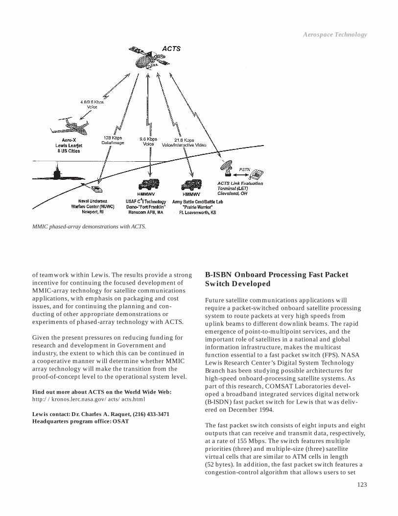
123
B-ISBN Onboard Processing Fast PacketSwitch Developed
Future satellite communications applications willrequire a packet-switched onboard satellite processingsystem to route packets at very high speeds fromuplink beams to different downlink beams. The rapidemergence of point-to-multipoint services, and theimportant role of satellites in a national and globalinformation infrastructure, makes the multicastfunction essential to a fast packet switch (FPS). NASALewis Research Center’s Digital System TechnologyBranch has been studying possible architectures forhigh-speed onboard-processing satellite systems. Aspart of this research, COMSAT Laboratories devel-oped a broadband integrated services digital network(B-ISDN) fast packet switch for Lewis that was deliv-ered on December 1994.
The fast packet switch consists of eight inputs and eightoutputs that can receive and transmit data, respectively,at a rate of 155 Mbps. The switch features multiplepriorities (three) and multiple-size (three) satellitevirtual cells that are similar to ATM cells in length(52 bytes). In addition, the fast packet switch features acongestion-control algorithm that allows users to set
of teamwork within Lewis. The results provide a strongincentive for continuing the focused development ofMMIC-array technology for satellite communicationsapplications, with emphasis on packaging and costissues, and for continuing the planning and con-ducting of other appropriate demonstrations orexperiments of phased-array technology with ACTS.
Given the present pressures on reducing funding forresearch and development in Government andindustry, the extent to which this can be continued ina cooperative manner will determine whether MMICarray technology will make the transition from theproof-of-concept level to the operational system level.
Find out more about ACTS on the World Wide Web:http://kronos.lerc.nasa.gov/acts/acts.html
Lewis contact: Dr. Charles A. Raquet, (216) 433-3471Headquarters program office: OSAT
Aerospace Technology
MMIC phased-array demonstrations with ACTS.

124
different thresholds for individual destination ports,thus throttling back the traffic from the transmittingport.
To allow for better characterization of the fast packetswitch, the Artificial Intelligence Group of Lewis’Digital System Technology Branch developed a user-friendly graphical user interface to the switch. By usingthe graphical interface, users can efficiently composecommands and generate command script files. Usersintuitively select commands from a graphical displayby using a mouse. When a command is selected,appropriate parameter options are displayed for furtherselection. Command instructions and data responses,respectively, are transmitted to and from the fast packetswitch via a direct RS-232 serial link. The fast packetswitch responses to commands are automaticallydisplayed and can be saved to a file for future reference.In addition, users can build a sequence of commandsinto a script that can be saved, loaded, edited, andexecuted at a later time.
Errors in command syntax are avoided because onlyappropriate parameters are offered for the selectedcommand name. Typing errors are avoided becauseusers enter data with the mouse. This intelligent userinterface also allows less-experienced users to quicklygenerate complicated scripts. Users do not have toremember all possible command codes, commandoptions, and corresponding formats. Later, the interfacewill be integrated with the artificial-intelligence shellKappa-PC. This shell could help users decide whichcommand or group of commands are needed toperform certain tasks. Also Kappa-PC can help usersselect appropriate command options.
Find out more about Lewis’ work with communicationssatellites on the World Wide Web:http://sulu.lerc.nasa.gov/
Lewis contacts: Jorge A. Quintana, (216) 433-6519, andTodd Quinn, (216) 977-1103Headquarters program office: OSAT
Fast packet switch interface.
Low-Complexity, Digital Encoder/ModulatorDeveloped for High-Data-Rate SatelliteB-ISDN Applications
The Space Electronics Division at the NASA LewisResearch Center is developing advanced electronictechnologies for the space communications and remotesensing systems of tomorrow. As part of the continu-ing effort to advance the state-of-the-art in satellitecommunications and remote sensing systems, Lewisdeveloped a low-cost, modular, programmable, andreconfigurable all-digital encoder-modulator (DEM) formedium- to high-data-rate radiofrequency communi-cation links. The DEM is particularly well suited tohigh-data-rate downlinks to ground terminals or directdata downlinks from near-Earth science platforms. Itcan support data rates up to 250 megabits per second(Mbps) and several modulation schemes, including thetraditional binary phase-shift keying (BPSK) andquadrature phase-shift keying (QPSK) modes, as wellas higher order schemes such as 8 phase-shift keying(8PSK) and 16 quadrature amplitude modulation(16QAM). The DEM architecture also can precompen-sate for channel disturbances and alleviate amplitudedegradations caused by nonlinear transpondercharacteristics.
In addition to higher order modulation schemes, acombination of modulation and forward-errorcorrection coding is used to improve the efficiency ofconveying information through the power- andbandwidth-limited channels that are characteristic ofspaceborne systems. In these systems, onboard powerand frequency allocation is at a premium. The DEM’sbaseline bandwidth efficient modulation techniqueprovides a factor of 2 improvement in bandwidthefficiency over the Consultative Committee for SpaceData Systems (CCSDS) standard and nearly 6 orders ofmagnitude improvement in quality of service. Thisfeature enables bandwidth-efficient, high-data-ratecommunications without requiring excessively sized,onboard radiofrequency power amplifiers, thusreducing overall spacecraft mass and power.
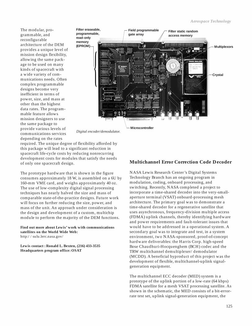
125
The modular, pro-grammable, andreconfigurablearchitecture of the DEMprovides a unique level ofmission design flexibility,allowing the same pack-age to be used on manykinds of spacecraft witha wide variety of com-munications needs. Oftencomplex programmabledesigns become veryinefficient in terms ofpower, size, and mass atother than the highestdata rates. The program-mable feature allowsmission designers to usethe same package toprovide various levels ofcommunications servicesdepending on the ratesrequired. The unique degree of flexibility afforded bythis package will lead to a significant reduction inspacecraft life-cycle costs by reducing nonrecurringdevelopment costs for modules that satisfy the needsof only one spacecraft design.
The prototype hardware that is shown in the figureconsumes approximately 18 W, is assembled on a 6U by160-mm VME card, and weighs approximately 40 oz.The use of low-complexity digital signal processingtechniques has nearly halved the size and mass ofcomparable state-of-the-practice designs. Future workwill focus on further reducing the size, power, andmass of the unit. An approach under consideration isthe design and development of a custom, multichipmodule to perform the majority of the DEM functions.
Find out more about Lewis’ work with communicationssatellites on the World Wide Web:http://sulu.lerc.nasa.gov/
Lewis contact : Ronald L. Bexten, (216) 433-3535Headquarters program office: OSAT
Field programmablegate array
Filter static randomaccess memory
Crystal
Microcontroller
Multichannel Error Correction Code Decoder
NASA Lewis Research Center’s Digital SystemsTechnology Branch has an ongoing program inmodulation, coding, onboard processing, andswitching. Recently, NASA completed a project toincorporate a time-shared decoder into the very-small-aperture terminal (VSAT) onboard-processing mesharchitecture. The primary goal was to demonstrate atime-shared decoder for a regenerative satellite thatuses asynchronous, frequency-division multiple access(FDMA) uplink channels, thereby identifying hardwareand power requirements and fault-tolerant issues thatwould have to be addressed in a operational system. Asecondary goal was to integrate and test, in a systemenvironment, two NASA-sponsored, proof-of-concepthardware deliverables: the Harris Corp. high-speedBose Chaudhuri-Hocquenghem (BCH) codec and theTRW multichannel demultiplexer/demodulator(MCDD). A beneficial byproduct of this project was thedevelopment of flexible, multichannel-uplink signal-generation equipment.
The multichannel ECC decoder (MED) system is aprototype of the uplink portion of a low-rate (64 kbps)FDMA satellite for a mesh VSAT processing satellite. Asshown in the schematic, the MED consists of a bit-error-rate test set, uplink signal-generation equipment, the
Digital encoder/demodulator.
Aerospace Technology
Filter eraseable,programmable,read-onlymemory(EPROM) Multiplexors

126
Unique-worddetector
Encoded block builder
Dataswitchinterface
MultichannelECCdecoder
UWD BLK MED DSI
TRWMCDD
Noisegenerator
23.04 MHz
Uplink signal-generation equipment
TRW MCDD special test equipment
Band-pass
Quadrature oscillator
Modulator
MEN MOD
Digitalcombiner andupconverter
DCU
Modulator
Modulator
Modulator
EMT QUO
CTL
Control distribution card
CLK
Clock distribution card
Time-shared decoder
Encoder/modulator timing card
MultichannelECCencoder
TRW MCDD (including radiofrequency and link-simulation equipment), and the time-shared decoder.The system can produce four uncoded or coded uplinkchannels at a channel transmission rate of 64 kbps. Thecodec uses a BCH block code in block sizes of 224 to 480bits excluding a 32-bit unique word preamble thatidentifies the start of a block.
This time-shared decoder has a very good potential forbeing applied in an onboard-processing circuit-switchenvironment because individual blocks of data can beprocessed and routed as soon as a full data block isavailable. Thus, the amount of storage memoryrequired onboard is reduced. For applications to apacket switch in an asynchronous FDMA environment,the time-shared decoder system would have to bemodified to align packets. This procedure would beprohibitively memory intensive and is notrecommended.
Testing was performed to characterize the informationchannels through the MCDD at various signal-to-noiselevels. In addition, the MCDD’s degraded guardchannels can be used for transmission with inferiorperformance. Therefore, the guard channels were alsocharacterized. Some parameters that were investigatedinclude coding block length, data pattern, unique wordvalue, and adjacent-channel interference. A final reportof the complete testing and characterization of thesystem will be available by January 1996.
Bibliography
Wagner, P.K.; and Ivancic, W.D.: Multichannel ErrorCorrection Code Decoder. AIAA Paper 94-1025 (NASA TM-106331), 1994.
Find out more about Lewis’ Digital Systems TechnologyBranch on the World Wide Web:http://sulu.lerc.nasa.gov/
Lewis contacts: Nitin J. Soni, (216) 433-6591, andWilliam D. Ivancic, (216) 433-3494Headquarters program office: OSAT
Uplink signal-generation equipment and time-shared decoder. Top: photo. Bottom: schematic.

127
The INTEX terminal can support organizationsinterested in additional qualified experiments withACTS for a wide range of investigations andapplications demonstrations.
To find out more about ACTS and Lewis’ CommunicationsProjects Branch, visit our sites on the World Wide Web:http://kronos.lerc.nasa.gov/acts/acts.htmlhttp://sulu.lerc.nasa.gov/5660.html
Lewis contact: Robert J. Kerczewski, (216) 433-3434Headquarters program office: OSAT
INTEX Ka-Band Experiment GroundTerminal
The INTEX (interference experiment) Ka-Band Experi-ment Ground Terminal was developed by NASA LewisResearch Center’s Advanced Space CommunicationsLaboratory to enable space communications experi-ments that use the Advanced CommunicationsTechnology Satellite (ACTS). INTEX is used for a widerange of ACTS technology validation and investigationexperiments as well as application demonstrations. Italso supports experiments for other organizationswithin and outside of NASA.
The INTEX Ground Terminal includes a 2.4-m parabolicantenna and a 40-W transmitter that can handle datarates from a few kilobits per second up to 300 megabitsper second (Mbps) through the ACTS matrix switchmode transponder. The primary experiment data ratesand modulations used with the INTEX terminal are T1(1.544 Mbps) and 48 Mbps using quadrature phase-shiftkeying (QPSK) modulation and 110 and 220 Mbpsusing serial minimum-shift-keyed (SMSK) modula-tion. The SMSK modem is capable of time-division,multiple-access (TDMA) bursted transmission atthroughput rates of 55, 27.5, and 13.8 Mbps. The INTEXground terminal also is completely compatible with theACTS High Burst Rate Link Evaluation Terminal(HBR-LET) terminal, allowing two-terminal duplexlink experiments.
Experiments performed so far include: determination ofthe effects of continuous-wave (CW) interference on ahigh-data-rate TDMA channel, determination of thetwo-tone response of the ACTS hardlimiter trans-ponder, determination of the effects of co-channel andadjacent channel interference, performance of multi-signal transmission, characterization of ACTS Ka-bandlink and transponder performance, evaluation ofINTEX and HBR-LET terminal performance, anddemonstration of bursted high-data-rate transmissionbetween TDMA terminals. Other experiments plannedor underway include evaluation of the effects of phasenoise on the bit error rate of low- and high-data-ratesignals, evaluation of the performance of digital video-compression techniques in the presence of noise andinterference, evaluation of the performance of high-ratio image compression applied to medical images,characterization of modulation and coding techniquesthrough the ACTS hardlimiter channel, and demon-stration and evaluation of satellite telemammographytechniques by transmission to remote medical facilities.
Telemammography Using SatelliteCommunications
The most effective method for improving survival ratesfor breast cancer, a leading cause of death amongAmerican women, is early detection through mammog-raphy. Because of certification requirements andeconomic reasons, most mammography experts arelocated in densely populated areas and in large medicalfacilities. Direct access to such expertise is unavailablefor millions of patients in rural, sparsely populated, andeconomically depressed areas. Telemammography, theelectronic transmission of digitized mammograms, canconnect these neglected patients with timely, criticalmedical expertise; however, an adequate terrestrialcommunications infrastructure does not exist in theseareas.
Fortunately, a number of major global satellite net-works are being developed for deployment at the endof this decade, bringing a low-cost telecommunicationsinfrastructure connection to virtually any location.NASA Lewis Research Center’s Advanced SpaceCommunications Laboratory is now working withleading breast cancer research hospitals, including theCleveland Clinic and the University of Virginia, toperform the critical research necessary to allow newsatellite networks to support telemammography.
The Satellite Telemammography Project recentlycompleted its first live demonstration: several digitizedmammography images were transmitted from Lewis to
Aerospace Technology

128
the ACTS Results Conference via the ACTS satellite T1VSAT Earth terminals. The Satellite TelemammographyProject is working on several critical technologyelements required for the future deployment of satellitetelemammography systems. One of these elementsis the determination of satellite link and image-compression parameters required for telemammogra-phy transmission. These parameters are needed todetermine the quality of the satellite link needed fortransmission and the maximum level of imagecompression that will maintain diagnostic accuracy.Another element is the need for faster and moreefficient image-compression algorithms, which arerequired to reduce the size of mammography imagefiles from up to 40 megabytes (MB) to 1 MB or less toallow fast transmission over T1 rate links. Also, theprocess must be integrated with hospital imagearchiving and communications systems.
Telemammography workstations with high-resolutionmedical image monitors are configured to allow thestudy of digitized mammograms and to apply image-
compression algorithms. The Advanced SpaceCommunications Laboratory satellite communicationstestbed will be used to establish satellite link andimage-compression parameters. To provide basicsatellite telemammography standards, expert mam-mographers will participate in studies that fulfill strictmedical and statistical requirements. ACTS satellite andground terminals will be used to test and demonstratelong-distance satellite telemammography betweenLewis and digital mammography research hospitals.The Satellite Telemammography Project will providesome of the most important communicationstechnology elements for enabling low-cost satellitetelemammography.
For more information about the research of Lewis’Communications Projects Branch, visit our site on theWorld Wide Web:http://sulu.lerc.nasa.gov/5660.html
Lewis contact: Robert J. Kerczewski, (216) 433-3434Headquarters program office: OSAT

129
1995 R&TSpace Flight Systems
ACTS ProjectCompilation and Analysis of 20- and30-GHz Rain Fade Events at the ACTSNASA Ground Station: Statistics andModel Assessment
Since the beginning of the operational phase of theNASA Research Center’s Advanced CommunicationTechnology Satellite (ACTS), signal-fade measurementshave been recorded at the NASA Ground Stationlocated in Cleveland, Ohio, with the use of the 20- and30-GHz beacon signals. Compilations of the daily datahave been statistically analyzed on a monthly andyearly basis. Such analyses have yielded relevantparameters as (1) cumulative monthly and yearlyprobability distributions of signal attenuation by rain,(2) attenuation duration versus attenuation thresholdprobabilities, and (3) rate-of-fade probabilities. Not onlyare such data needed for a realistic data base to supportthe design and performance analysis of future satellitesystems, but they are necessary to assess predictionsmade with the ACTS Rain Attenuation PredictionModel.
Bibliography
Manning, R.M.: Compilation and Analysis of 20- and 30-GHzRain Fade Events at the ACTS NASA Ground Station:Statistics and Model Assessment. ACTS Results Conference.Cleveland, Ohio. Sept. 11-13, 1995
Find out more about ACTS on the World Wide Web:http://kronos.lerc.nasa.gov/acts/acts.html
Lewis contact: Dr. Robert M. Manning, (216) 433-6750Headquarters program office: OSAT
Using the ACTS Rain Attenuation PredictionModel to Identify and Specify Communica-tions System Performance Parameters
The Advanced Communication Technology Satellite(ACTS) Rain Attenuation Prediction Model was used intwo satellite communication scenarios. In particular,propagation links from ACTS to and from Cleveland,Ohio, and Nashville, Tennessee, were considered.Software for the model, which has existed for 5 years,is known as the NASA Lewis Research Center SatelliteLink Attenuation Model program, or LeRC-SLAM,Version 1.1. (This model and its software implemen-tation won the Space Act Award for 1992.) The model isapplicable for any location in the continental UnitedStates with a spatial resolution of 0.5º in both longitudeand latitude. The frequency of operation of the com-munications link can be within the range inclusive from1 to 1000 GHz. Other parameters needed to use thissoftware are reviewed in reference 1. The analysis thatis given here is for the ACTS communication linksmentioned above. In addition to the details given bythis version of the LeRC-SLAM software, a newperformance parameter, as well as the associatedconcept of rain fade controller availability (“rain fade”refers to the attenuation of a signal by rain), is used tooptimize link performance. It is the purpose of LeRC-SLAM to demonstrate the use of these relevant para-meters in the design of such communications links.
Bibliography
Manning, R.M.: Using the ACTS Rain Attenuation PredictionModel to Identify and Specify Communications SystemPerformance Parameters. ACTS Results Conference,Cleveland, Ohio, Sept. 11-13, 1995.
LeRC-SLAM (order number LEW-14979) is available fromCOSMIC—NASA’s Software Technology Transfer Center.Contact COSMIC by phone (706) 542-3265, by fax (706)542-4807, or on the World Wide Web (http:www.cosmic.uga.edu/).
Find out more about ACTS on the World Wide Web:http://kronos.lerc.nasa.gov/acts/acts.html
Lewis contact: Dr. Robert M. Manning (216) 433-6750Headquarters program office: OSAT

130
ACTS Aeronautical Terminal Experiment(AERO-X)
During the summer of 1994, the performance of anexperimental mobile satellite communication systemwas demonstrated. Using the Advanced Communi-cations Technology Satellite (ACTS) and the ACTSMobile Terminal (AMT), the system demonstrated anactive Monolithic Microwave Integrated Circuit(MMIC) phased-array antenna system. The antennasystem was installed onboard one of NASA LewisResearch Center’s research aircraft, a Learjet Model 25.It proved the viability of in-flight satellite communi-cations services via small, flush, mountable electronicphased-array antennas. The top left figure illustratesthe overall system setup for the ACTS AeronauticalTerminal Experiment (AERO-X). The Link EvaluationTerminal (LET) at Lewis in Cleveland, Ohio, interfacedwith fixed-AMT equipment, providing a seamlessconnection with the Public Service Telephone Network.As the Learjet was flown over several major citiesacross the U.S., this demonstration system allowedpassengers onboard to make telephone calls as if theywere using a cellular system. ACTS was operated in itsmicrowave switch matrix mode with a spot beam forthe Learjet and another spot beam dedicated to the LET.
ACTS is a proof-of-concept 30/20-GHz satellitelaunched by the Space Shuttle Discovery (STS-51) inSeptember 1993. It has been operating ever since andcontinues to validate key technologies such as (1) thesatellite multibeam antenna, which produces multiplehigh-gain spot beams that can be rapidly hopped,scanned, or fixed; (2) the baseband processor, whichdemodulates, routes individual circuit-switchedmessages, and remodulates; and (3) the microwaveswitch matrix, which handles up to 9000-MHz band-width signals and provides rapidly reconfigurableconnectivity between the spot beams. The bottomfigure on the next page shows satellite coverageafforded by the ACTS satellite.
The AMT is a mobile terminal designed to demonstratethe viability of speech (at 2.4, 4.8, and 9.6 kilobits persecond (kbps)) and data transmission (at 2.4, 4.8, 9.6,and 64 kpbs) in the 30/20-GHz mobile satellite com-munications environment. The speech codec uses theGovernment standard LPC-10, the proposed CELPGovernment standard, and MRELP (Motorola’sproprietary algorithm). Its modem implements asimple, but robust, differential phase shift keying(DPSK) scheme with a rate convolutional codingand interleaving.
Implications of ACTS Technology on theRequirements of Rain Attenuation Modelingfor Communication System Specificationand Analysis at the Ka-Band and Beyond
With the advent of the use of the Ka-band for spacecommunications, coupled with the introduction ofdigital modulation techniques as well as multiple-beammethodology for satellites, the NASA Lewis ResearchCenter has deemed it necessary to reassess the plethoraof rain attenuation prediction models in use (computermodels that predict the attenuation of signals by rain).The Advanced Communication Technology Satellite(ACTS) project, undertaken by NASA in 1983, offeredsuch challenges to rain attenuation prediction model-ing. An examination of the work done in this areashows that, up to 1983, no such single modeling for-malism existed that could fulfill the requirements of theACTS specifications. Not even the work done by theNASA Propagation Experimenters Group had envision-ed such requirements, so no dynamic Ka-band dataexisted from which one could draw conclusions.
In response to this need, Lewis developed the ACTSRain Attenuation Prediction Model. A detaileddiscussion of the derivation of the model’s basicrelations can be found in reference 1. The model as wellas its software implementation won the Space ActAward for 1992. In addition to the review of the model,a recommendation is given in reference 2 for a newevaluation of the performance of satellite commun-ication systems, in particular, for those to be operatingwithin the Ka-band and above. These systems willnecessarily employ some type of dynamic rain-fademitigation procedure.
References
1. Manning, R.M.: A Unified Statistical Rain-Attenuation Model for Communication Link Fade Predictions and Optimal Stochastic Fade Control Design Using a Location- Dependent Rain-Statistics Database. Int. J. Satellite Comm., vol. 8, 1990, pp. 11-30.
2. Manning, R.M.: The Implications of ACTS Technology on the Requirements of Rain Attenuation Modeling for Communication System Specification and Analysis at 30/20 GHz and Beyond. ACTS Results Conference, Cleveland, Ohio, Sept. 11-13, 1995.
Find out more about ACTS on the World Wide Web:http://kronos.lerc.nasa.gov/acts/acts.html
Lewis contact: Dr. Robert M. Manning, (216) 433-6750Headquarters program office: OSAT
1 2

131
the rectangles represent the predicted performance. TheAERO-X program provided an opportunity to show-case many proof-of-concept technologies found in theACTS satellite, the active phased-array antennas, andthe AMT.
Reference
1. Raquet, C., et al.: Ka-Band MMIC Arrays for ACTS Aero Terminal Experiment. Presented at the 43rd Congress of the International Astronautical Federation. Aug. 28 to Sept. 5, 1992.
Find out more about ACTS on the World Wide Web:http://kronos.lerc.nasa.gov/acts/acts.html
Lewis contacts: Sina Javidi, (216) 433-8326, and RichardReinhart, (216) 433-6588Headquarters program office: OSAT
Ka-band data andpilot (29.634 GHz)
Ka-band data(29.634 GHz)
K-band data (19.914 GHz)and pilot (19.914 GHz)
Ka-band data(19.914 GHz)
ACTS Link EvaluationTerminal (LET)
NASA Lew
is
Clevela
nd, O
hio
56
54
52
50
48
46
44
42
40
3821.3 21.5 21.6 21.7 21.8 21.9 22.0 22.121.4
Top left: System setup. Top right: Inbound link carrier-to-noise density versus Greenwich Mean Time (GMT). Bottom: ACTS satellite coverage.
The MMIC phased-array antenna system (ref. 1)consisted of one transmit array antenna and two receivearray antennas. The antennas were mounted inside theLearjet, looking out the standard Plexiglass window.These array antennas incorporated individual GaAsMMIC devices for the individual radiating elements forelectronic beam steering and distributed power amplifi-cation. An open-loop antenna controller developed byLewis used information from the global positioningsystem and aircraft gyroscopes to electronically steerthe array beams toward ACTS during flight.
During the demonstration flights, link performancedata were recorded with a power meter, a spectrumanalyzer, a calibrated 31.8-kHz bandpass filter, and aglobal positioning system receiver. In the top rightfigure (which shows the inbound carrier-to-noise ratio),the continuous trace is the measured performance and
Space Flight Systems
Time, GMT
Car
rier
-to
-no
ise
den
sity

132
ACTS MULTIBEAM ANTENNA RADIOFREQUENCY POINTING VARIATIONS
Type Beam Magnitude, Axis Duration Operational effect deg
Rapidly East Less than Roll Less than Short-term effect marginalvarying 0.1 1 hr station. Use ESA control during
event to minimize effect.
Diurnal East and West .2 Pitch 12 hr/event Significant signal variation canvariation crash stations. Use biax drive to
compensate.
Quasistatic East and West ±.04 Pitch 14 days Totally compensated by Autotrack ±.02 Roll
Vibration Transmit ±.15 Pitch 1 Hz Generally negligible
Advanced Communication TechnologySatellite (ACTS) Multibeam AntennaOn-Orbit Performance
Introduction
The NASA Lewis Research Center’s AdvancedCommunication Technology Satellite (ACTS) waslaunched in September 1993. ACTS introduced severalnew technologies, including a multibeam antenna(MBA) operating at extremely short wavelengths neverbefore used in communications. This antenna, whichhas both fixed and rapidly reconfigurable high-energyspot beams (150 miles in diameter), serves usersequipped with small antenna terminals.
Extensive structural and thermal analyses have beenperformed for simulating the ACTS MBA on-orbitperformance. The results show that the reflector sur-faces (mainly the front subreflector), antenna supportassembly, and metallic surfaces on the spacecraft bodywill be distorted because of the thermal effects ofvarying solar heating, which degrade the ACTS MBAperformance.
Since ACTS was launched, a number of evaluationshave been performed to assess MBA performance in thespace environment. For example, the on-orbit perfor-mance measurements found systematic environmen-tal disturbances to the MBA beam pointing. Thesedisturbances were found to be imposed by the attitude
control system, antenna and spacecraft mechanicalalignments, and on-orbit thermal effects. As a result,the MBA may not always exactly cover the intendedservice area. In addition, the on-orbit measurementsshowed that antenna pointing accuracy is theperformance parameter most sensitive to thermaldistortions on the front subreflector surface andantenna support assemblies.
Several compensation approaches were tested andevaluated to restore on-orbit pointing stability. Acombination of autotrack (75 percent of the time) andEarth sensor control (25 percent of the time) was foundto be the best way to compensate for antenna pointingerror during orbit. This approach greatly minimizes theeffects of thermal distortions on antenna beampointing.
Summary of Results
• Analysis and on-orbit measurements of the ACTS MBA performance indicated that thermal distortions are periodic. The table describes the system’s effect with and without compensation for ground stations within a single spot beam.
133
• In future commercial communications satellites that use multibeam reflector systems at the Ka band (or that use gridded reflector structures and materials such as Aztroquartz (GE Astro, East Windsor, New Jersey) at higher frequencies), a sunshade should be employed to avoid large thermal distortions.• The mechanical oscillations (nonthermal distortions) on the ACTS MBA are very difficult to compensate for. Future communications satellites should consider the mechanical oscillations a driver in their antenna mechanical design.• The yaw control system can affect the beam pointing drastically, especially for those ground stations located away from either subsatellite longitude or autotrack boresight. Future spacecraft systems should take into account yaw estimation as a primary concern in their design goals.• The ACTS MBA performance was found to be well within the expected range, and the transmit and receive beam optimization procedures were suc- cessfully executed. On-orbit MBA measurements have shown that all design limits have been met and that good pointing performance has been achieved.
Lewis contacts: Dr. Roberto J. Acosta, (216) 433-6640, andDavid L. Wright, (216) 433-3530Headquarters program office: OSAT
(carbon dioxide and water vapor) and brings in freshoxygen for the flame. In the microgravity environmentaboard spacecraft, the predominant flows are the veryslow air ventilation flows rather than buoyancy.
The Radiative Ignition and Transition to SpreadInvestigation (RITSI) is a shuttle middeck Gloveboxcombustion experiment developed by the NASA LewisResearch Center, the National Institute for Standardsand Technology (NIST), and Aerospace Design andFabrication (ADF). It is scheduled to fly on the thirdUnited States Microgravity Payload (USMP-3) missionin February 1996. The objective of RITSI is to experi-mentally study radiative ignition and the subsequenttransition to flame spread in low gravity in the presenceof very low speed air flows in two- and three-dimensional configurations.
Toward this objective, a unique collaboration betweenNASA, NIST, and the University of Hokkaido wasestablished to conduct 15 science and engineering testsin Japan’s 10-sec drop shaft. For these tests, the RITSIengineering hardware was mounted in a sealed cham-ber with a variable oxygen atmosphere. Ashless filterpaper was ignited during each drop by a tungsten-halogen heat lamp focused on a small spot in the centerof the paper. The flame spread outward from that point.Data recorded included fan voltage (a measure of airflow), radiant heater voltage (a measure of radiativeignition energy), and surface temperatures (measuredby up to three surface thermocouples) during ignitionand flame spread. In addition, color video and 35-mmfilm pictures were taken during the drop.
Data from these tests are still being reduced andanalyzed, but some observations can be reported.Radiative ignition in low gravity was successfullyachieved for the first time. Preliminary findingsindicate that the spread of flames upwind into freshoxygen was enhanced by the very low speed flows, aswas anticipated from model predictions and previousexperimental results (refs. 1 and 2). Downwind flamespread was less robust because of the presence of theupwind flame, which vitiates the atmosphere for thedownwind flame, in agreement with modeling results,as shown in the figure (ref. 1).
References
1. McGrattan, K.B., et al.: Effects of Ignition and Wind on the Transition to Flame Spread in a Microgravity Environment. Accepted for publication in Combustion and Flame, 1996.
2. Olson, S.L.: Mechanisms of Microgravity Flame Spread Over a Thin Solid Fuel: Oxygen and Opposed Flow Effects. Combust. Sci. Tech., vol. 76, 1991, pp. 233-249.
Space Flight Systems
Space Experiments
Radiative Ignition and the Transition toFlame Spread Investigated in the JapanMicrogravity Center’s 10-sec Drop Shaft
In space, many things react differently because of thelack of gravity. One area of concern is how fire ignitesand reacts in a microgravity environment. Fires inspacecraft pose significant dangers to the crew: toxicproducts could quickly poison the atmosphere and bedifficult to remove, large-scale production of gases athigh temperatures could overpressurize the spacecraft,and extinguishing systems might damage the electricalsystems. Although momentary ignitions due to elec-trical short–circuiting or overheating might be anacceptable and recoverable hazard, a transition from anignition to large-scale fire growth is an unacceptablerisk. To stop this transition, the environmental con-ditions that allow transition must be avoided. Theseconditions are not yet well known because, on Earth,buoyant flow removes the products of combustion

134
0
3
1
2
4
cm
1.5 sec
.05
.15
.25
.25
.15
.05.15
0
3
1
2
4
cm
1.0 sec
.25.05
.25.15
.25
Oxygen content,mol percent
0
3
1
2
4
cm
0.5 sec
–2 40
–1
3
–3–4
1
2
4
cm
3210
2.0 sec
.25
.15
.05
.25
.15
.05
cm
Flame transition to spread after radiative ignition. Gas flow entersfrom the left. Solid lines are reaction contours, which can becompared to flame shape; and dashed lines are oxygen concen-tration contours. Note the upstream flame (to the left) is almostimmediately more vigorous and that the downstream flame diesaway because of the oxygen “shadow” cast by the upstream flame.
Find out more about RITSI and other Lewis microgravityexperiments on the World Wide Web:http://zeta.lerc.nasa.gov/expr/ritsi.htmhttp://microgravity.msad.hq.nasa.gov/cScienceProg/subdisc/combust.htmlhttp://zeta.lerc.nasa.gov/sedhome.htmhttp://www.lerc.nasa.gov/WWW/MCFEP/
Lewis contact: Sandra L. Olson, (216) 433-2859Headquarters program office: OLMSA (MSAD)
Soot Imaging and Measurement
Soot, sometimes referred to as smoke, is made upprimarily of the carbon particles generated by mostcombustion processes. For example, large quantities ofsoot can be seen issuing from the exhaust pipes ofdiesel-powered vehicles. Heated soot also is responsiblefor the warm orange color of candle flames, though thatsoot is generally consumed before it can exit the flame.Research has suggested that heavy atmospheric sootconcentrations aggravate conditions such as pneu-monia and asthma, causing many deaths each year.
To understand the formation and oxidation of soot,NASA Lewis Research Center scientists, together withseveral university investigators, are investigating theproperties of soot generated in reduced gravity, wherethe absence of buoyancy allows more time for theparticles to grow. The increased time allows researchersto better study the life cycle of these particles, with thehope that increased understanding will lead to bettercontrol strategies. To quantify the amount of sootpresent in a flame, Lewis scientists developed a uniqueimaging technique that provides quantitative andqualitative soot data over a large field of view. There issignificant improvement over the single-point methodsnormally used.
The technique is shown in the sketch, where lightfrom a laser is expanded with a microscope objective,
mol %
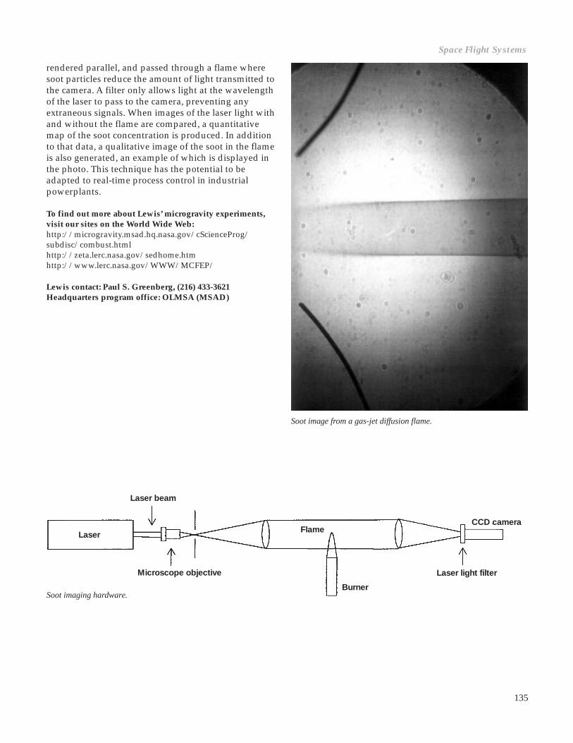
135
rendered parallel, and passed through a flame wheresoot particles reduce the amount of light transmitted tothe camera. A filter only allows light at the wavelengthof the laser to pass to the camera, preventing anyextraneous signals. When images of the laser light withand without the flame are compared, a quantitativemap of the soot concentration is produced. In additionto that data, a qualitative image of the soot in the flameis also generated, an example of which is displayed inthe photo. This technique has the potential to beadapted to real-time process control in industrialpowerplants.
To find out more about Lewis’ microgravity experiments,visit our sites on the World Wide Web:http://microgravity.msad.hq.nasa.gov/cScienceProg/subdisc/combust.htmlhttp://zeta.lerc.nasa.gov/sedhome.htmhttp://www.lerc.nasa.gov/WWW/MCFEP/
Lewis contact: Paul S. Greenberg, (216) 433-3621Headquarters program office: OLMSA (MSAD)
Laser light filter
CCD camera
Laser
Microscope objective
Laser beam
Flame
BurnerSoot imaging hardware.
Soot image from a gas-jet diffusion flame.
Space Flight Systems

136
Microgravity Turbulent Gas-Jet DiffusionFlames
A gas-jet diffusion flame is similar to the flame on aBunsen burner, where a gaseous fuel (e.g., propane)flows from a nozzle into an oxygen-containingatmosphere (e.g., air). The difference is that a Bunsenburner allows for (partial) premixing of the fuel andthe air, whereas a diffusion flame is not premixed andgets its oxygen (principally) by diffusion from theatmosphere around the flame. Simple gas-jet diffusionflames are often used for combustion studies becausethey embody the mechanisms operating in accidentalfires and in practical combustion systems (see thesketch on the left side of the figure).
However, most practical combustion is turbulent (i.e.,with random flow vortices), which enhances the fuel/air mixing. These turbulent flames are not wellunderstood because their random and transient naturecomplicates analysis. Normal gravity studies of tur-bulence in gas-jet diffusion flames can be impeded bybuoyancy-induced instabilities. These gravity-causedinstabilities, which are evident in the flickering of acandle flame in normal gravity, interfere with the studyof turbulent gas-jet diffusion flames. By conductingexperiments in microgravity, where buoyant instabil-ities are avoided, we at the NASA Lewis ResearchCenter hope to improve our understanding of turbulentcombustion. Ultimately, this could lead to improve-ments in combustor design, yielding higher efficiencyand lower pollutant emissions.
Gas-jet diffusion flames are often researched as modelflames, because they embody mechanisms operating inboth accidental fires and practical combustion systems(see the first figure). In normal gravity laboratoryresearch, buoyant air flows, which are often negligiblein practical situations, dominate the heat and masstransfer processes. Microgravity research studies,however, are not constrained by buoyant air flows, andnew, unique information on the behavior of gas-jetdiffusion flames has been obtained.
The graph shows the observed flame height as afunction of the fuel-injection Reynolds number (whichis related to the fuel flow rate for a given injectionnozzle size) for flames in both normal gravity andmicrogravity. Below a Reynolds number of approxi-mately 2000, both flames exhibit laminar characteristics,and the flame height increases with an increase in theReynolds number. Because of the lack of buoyantconvection, which enhances combustion in normalgravity, the microgravity flames are larger.
In the Reynolds number range of 2000 to 3000, theflames undergo a transition process from laminar toturbulent burning. In normal gravity, this process ischaracterized by a decrease in the flame height and theappearance of instabilities (flame disturbances) thatfirst appear near the flame tip but begin to originate atlower locations with increases in Reynolds number. In
Soot
Chemicalreaction Radiation
Diffusion
Acceleration
Entrainment
Flamestabilization
Fuel
0 6x10³
Reynolds number, Re
0
20
10
30
40
Lum
ino
us f
lam
e he
ight
, cm
0g flame1g flame
1 2 3 4 5
Left: Schematic of the structure of a gas-jet diffusion flame. Right: Measured flame height as a function of injection Reynoldsnumber for propane-air flames in microgravity and normal gravity.

137
microgravity, the flame height continues to increase,although at a lower rate than in the laminar regime. Incontrast to the normal gravity case, flame disturbancesin microgravity are first observed near the base of theflame instead of near the tip. Flame instabilities ariseprimarily at locations of large velocity gradients. Innormal gravity, because of buoyant acceleration,velocity gradients are maximum near the flame tip soinstabilities are first observed there. In microgravity,velocity gradients are maximum near the base of theflame, and that is where disturbances are first observed.
Beyond a Reynolds number of approximately 3000,turbulent conditions prevail. In normal gravity, in theturbulent regime, the flame height remains constantwith the Reynolds number until close to flame blowoff.This feature is explained in terms of a balance betweenturbulent transport processes and jet momentum.However, in microgravity, the flame height continues toincrease with Reynolds number, indicating that jetmomentum dominates turbulent transport in this case.
The normal gravity behavior shown in the secondfigure is similar to that appearing in virtually allcombustion science textbooks. It was anticipated thatbuoyant effects in the turbulent regime would be smalland that the behavior of microgravity and normalgravity flames would be identical. This is obviously notthe case. We anticipate that microgravity data, whichgive better insights into the controlling mechanisms forgas-jet diffusion flames, will find its way into textbooksof the future.
Learn more about microgravity on the World Wide Web:NASA Headquarters:http://microgravity.msad.hq.nasa.gov/NASA Lewis Research Center:http://zeta.lerc.nasa.gov/
Lewis contact: Dennis P. Stocker, (216) 433-2166Headquarters program office: OLMSA (MSAD)
Spread Across Liquids: The World’s FirstMicrogravity Combustion Experiment ona Sounding Rocket
The Spread Across Liquids (SAL) experiment charac-terizes how flames spread over liquid pools in a low-gravity environment in comparison to test data atEarth’s gravity and with numerical models. Themodeling and experimental data provide a morecomplete understanding of flame spread, an area oftextbook interest, and add to our knowledge abouton-orbit and Earthbound fire behavior and fire hazards.The experiment was performed on a sounding rocketto obtain the necessary microgravity period. Suchcrewless sounding rockets provide a comparativelyinexpensive means to fly very complex, and potentiallyhazardous, experiments and perform reflights at a verylow additional cost. SAL was the first sounding-rocket-based, microgravity combustion experiment in theworld.
It was expected that gravity would affect ignitionsusceptibility and flame spread through buoyantconvection in both the liquid pool and the gas abovethe pool. Prior to these sounding rocket tests, however,it was not clear whether the fuel would ignite readilyand whether a flame would be sustained in micro-gravity. It also was not clear whether the flame spreadrate would be faster or slower than in Earth’s gravity.
The SAL experiment flew twice in the past year, andboth flights were highly successful, revealing newflame-spread behavior attributable to the absence ofgravitational effects and also proving the feasibility inmicrogravity of several novel, advanced diagnosticsand fluid management technologies. The diagnosticinstruments, which performed flawlessly, included fourflame-imaging cameras, two side-viewing particleimage velocimetry (PIV) systems that recorded liquidfuel-flow patterns, an infrared camera that determinedthe liquid surface temperature field ahead of the flame,and a rainbow schlieren deflectometer that imaged thesubsurface-liquid temperature gradients.
In Earth’s gravity (1g), flames spread in a regularlypulsating manner. In these microgravity (µg) tests,however, flames spread very slowly and uniformlyacross the entire length of the pool (see the graph).Unlike flames in 1g, the microgravity flame wascompletely blue (soot-free), without any noticeableplume or wavering. (See the comparative photos of aflame in 1g and in microgravity at the bottom of thenext page.) The diagnostic instruments showed a largeliquid-phase vortical flow extending deep into
Space Flight Systems
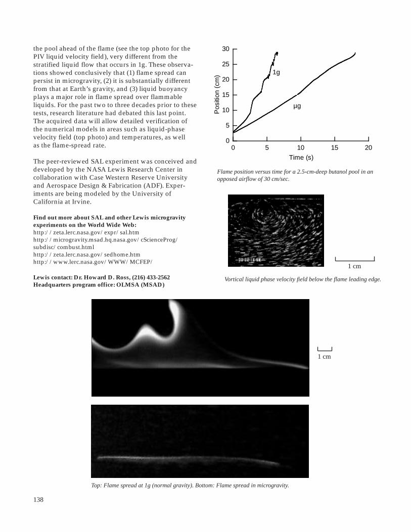
138
the pool ahead of the flame (see the top photo for thePIV liquid velocity field), very different from thestratified liquid flow that occurs in 1g. These observa-tions showed conclusively that (1) flame spread canpersist in microgravity, (2) it is substantially differentfrom that at Earth’s gravity, and (3) liquid buoyancyplays a major role in flame spread over flammableliquids. For the past two to three decades prior to thesetests, research literature had debated this last point.The acquired data will allow detailed verification ofthe numerical models in areas such as liquid-phasevelocity field (top photo) and temperatures, as wellas the flame-spread rate.
The peer-reviewed SAL experiment was conceived anddeveloped by the NASA Lewis Research Center incollaboration with Case Western Reserve Universityand Aerospace Design & Fabrication (ADF). Exper-iments are being modeled by the University ofCalifornia at Irvine.
Find out more about SAL and other Lewis microgravityexperiments on the World Wide Web:http://zeta.lerc.nasa.gov/expr/sal.htmhttp://microgravity.msad.hq.nasa.gov/cScienceProg/subdisc/combust.htmlhttp://zeta.lerc.nasa.gov/sedhome.htmhttp://www.lerc.nasa.gov/WWW/MCFEP/
Lewis contact: Dr. Howard D. Ross, (216) 433-2562Headquarters program office: OLMSA (MSAD)
Top: Flame spread at 1g (normal gravity). Bottom: Flame spread in microgravity.
Flame position versus time for a 2.5-cm-deep butanol pool in anopposed airflow of 30 cm/sec.
1g
µg
Pos
ition
(cm
)
Time (s)
0 5 10 15 200
5
10
15
20
25
30
Vortical liquid phase velocity field below the flame leading edge.
1 cm
1 cm
139
Two U.S. Experiments to Fly AboardEuropean Spacelab Facility in 1996
Space provides researchers a way to study the behaviorof fluids when the forces of gravity are removed. Thestudies described here involve international coopera-tive research projects to study various aspects of fluidbehavior in a microgravity environment. These projectsutilize the Bubble Droplet Particle Unit (BDPU), whichwas built by the European Space Agency’s (ESA)Technology Center in Noordwijk, The Netherlands.This Spacelab-based multiuser facility flew for thefirst time in July 1994 on the second InternationalMicrogravity Laboratory (IML-2). It is scheduled forreflight on the Life and Microgravity Sciences (LMS)mission in June 1996. This experiment hardware wasdesigned primarily to conduct fluid physics experi-ments with transparent fluids. LMS will fly bothEuropean and U.S. investigations, including experi-ments defined by Professor R.S. Subramanian ofClarkson University in Potsdam, New York, andProfessor S.A. Saville of Princeton University,Princeton, New Jersey.
Professor Subramanian’s experiment (a reflight fromIML-2), Thermocapillary Migrations and Interactions ofBubbles and Drops, will study the bubble’s (or droplet’s)velocity and shape as it travels (or migrates) throughanother fluid that has a linear temperature distribution.During the experiment, local temperature gradientsaround the bubble will impose a surface tensiongradient on the bubble interface and produce motion inthe interface film. This motion will cause a jetting actionthat will propel the bubble toward the relatively hotterareas of the surrounding fluid. The LMS experimentswill emphasize bubble (and droplet) pair interactionsand different fluid combinations to expand theknowledge gained from the IML-2 experiment. Themicrogravity environment will isolate the thermo-capillary phenomena from the normally dominanteffects of buoyancy and natural convection on Earth.Results from these types of experiments have applica-tions on Earth in ceramic and glass formation, as wellas in metal and alloy solidification. Better understand-ing of these thermocapillary effects can lead, as well,to superior bubble management techniques for space-based crew life-support systems.
Professor Saville’s experiment, Studies in Electrohydro-dynamics, looks at the stabilizing effects of high-voltageelectric fields on liquid columns. Liquid columns of agiven length-to-diameter ratio will be established inmicrogravity and exposed to various electric fieldstrengths. In the absence of an electric field, thesecolumns will deform into increasingly amphoric shapes
and eventually pinch off. The main scientific points ofinterest to be studied when the electric field is appliedwill be to determine what minimum electric fieldstrengths are needed to maintain cylindrical columnsand what minimum field strengths are required toprevent pinch off. Liquid columns in gas, as well ascolumns in other immiscible liquids, will be studied.
Long-term microgravity is particularly needed to studyliquid columns that are surrounded by a gas. Theliquid-in-liquid cases will be compared with similarground-based experiments. These ground-based testswere done in a simulated low gravity for which the twoliquids were density matched. Liquid-gas cases havethe advantage of being significantly easier to analyzebecause of simpler boundary conditions. Applicationsof improved models and theory from these experimentsare expected in processes that involve liquid columns.These processes may, then, be improved through theuse of electrohydrodynamics effects. Examples of theseprocesses include fiber spinning, crystal growth, andliquid jets (e.g., for printers).
The Bubble Droplet Particle Unit facility and its variousprincipal-investigator-specific test containers weredesigned and constructed under the European SpaceAgency’s Technology Center management by variousEuropean-based contractors. NASA Lewis ResearchCenter’s function is to assist in the design and flightoperations of the two U.S. Bubble Droplet Particle Unitexperiments.
Find out more about Lewis microgravity experiments on theWorld Wide Web:http://zeta.lerc.nasa.gov/sedhome.htmhttp://liftoff.msfc.nasa.gov/spacelab/lmshttp://www.lerc.nasa.gov/WWW/MCFEP/
Lewis contact: Myron E. Hill, (216) 433-5279Headquarters program office: OLMSA (MSAD)
Space Flight Systems

140
Interface Configuration Experiments (ICE)Explore the Effects of Microgravity on Fluids
The Interface Configuration Experiment (ICE) isactually a series of experiments that explore the strikingbehavior of liquid-vapor interfaces (i.e., fluid surfaces)in a low-gravity environment under which major shiftsin liquid position can arise from small changes incontainer shape or contact angle. Although theseexperiments are designed to test current mathematicaltheory, there are numerous practical applications thatcould result from these studies. When designing fluidmanagement systems for space-based operations, it isimportant to be able to predict the locations andconfigurations that fluids will assume in containersunder low-gravity conditions. The increased ability topredict, and hence control, fluid interfaces is vital tosystems and/or processes where capillary forces play asignificant role both in space and on the Earth. Some ofthese applications are in general coatingprocesses (paints, pesticides, printing, etc.),fluid transport in porous media (ground waterflows, oil recovery, etc.), liquid propellantsystems in space (liquid fuel and oxygen),capillary-pumped loops and heat pipes, andspace-based life-support systems.
In space, almost every fluid system is affected,if not dominated, by capillarity. Knowledge ofthe liquid-vapor interface behavior, and inparticular the interface shape from which anyanalysis must begin, is required as afoundation to predict how these fluids willreact in microgravity and on Earth. With suchknowledge, system designs can be optimized,thereby decreasing costs and complexity,while increasing performance and reliability.ICE has increased, and will continue toincrease this knowledge, as it probes thespecific peculiarities of current theory uponwhich our current understanding of theseeffects is based.
Several versions of ICE were conductedin NASA Lewis Research Center’s droptowers and on the space shuttle during thefirst and second United States MicrogravityLaboratory missions (USML-1 and USML-2).Additional tests are planned for the spaceshuttle and for the Russian Mir space station.These studies will focus on interfacialproblems concerning surface existence,uniqueness, configuration, stability, andflow characteristics.
Results to date have clearly demonstrated the need forexperimental data regarding the behavior of large-scalecapillary surfaces in containers of irregular cross-section. For example, ICE on USML-1 revealed theexistence of a globally stable, asymmetric interfaceconfiguration in a rotationally symmetric container. Formany applications, the possibility of encountering suchsurfaces must be considered because they may bedetrimental to the operation of a system in space. Aresult from the USML-2 mission revealed that fluidlocations after long-duration exposures (days) to lowgravity can be significantly different than for shortdurations (hours). This fact raises concerns both fordesigners of space systems and for scientists in that trueequilibrium for certain capillary surfaces may takedays, even weeks, to be achieved.
Top: ICE flight hardware (“exotic” vessels) for USML-1. Bottom: ICE flight cellsfor USML-2: proboscis (three) and wedge vessels (one).

141
These experiments were conceived and developed byPaul Concus of Lawrence Berkeley Laboratory and theUniversity of California at Berkeley, Robert Finn ofStanford University, and Mark Weislogel of the NASALewis Research Center in Cleveland, Ohio. Thehardware was designed and built at Lewis.
To find out more about Lewis’ microgravity experiments,visit our sites on the World Wide Web:http://microgravity.msad.hq.nasa.gov/cScienceProg/subdisc/fluids.htmlhttp://zeta.lerc.nasa.gov/
Lewis contact: Mark M. Weislogel, (216) 433-2877Headquarters program office: OLMSA (MSAD)
separately to the Kennedy Space Center and integratethe packages into the Spacelab racks there. Thecomplexity of the hardware and the requirement todeliver the hardware nearly 18 months quicker thannormal for a project of this size led to the decision forthe integration process to take place at Lewis.
Lewis management made other decisions to meet thelaunch date. One of these decisions was to do thedesign, development, and fabrication in house and touse the resources available at Lewis and the GreaterCleveland area. To date, nearly 40 fabrication shopsacross Northeastern Ohio have contributed to makingthe project a reality. The strategy is working, becausethe project is still on schedule after 2 years.
Combustion Module 1: Spacelab RacksIntegrated at the Lewis Research Centerfor the First Time
The Combustion Module-1 (CM-1), NASA’s largest(over 1800 lb) and one of the most sophisticatedcombustion experiments ever to fly on the Spacelab,will be carried on the first Microgravity ScienceLaboratory (MSL-1) mission aboard the space shuttleflight STS-84 in April 1997. The CM-1 project is astepping stone to the space station era, because thehardware can support multiple investigators on thesame mission and can be integrated at user locationsand shipped to the launch site. CM-1 is being devel-oped to accommodate microgravity combustionexperiments that are designed to help explain andpredict the behavior of combustion processes. Althoughthe two principal investigators for CM-1 are bothstudying combustion processes, their investigationsare quite different. Professor Paul D. Ronney of theUniversity of Southern California will examine theStructures of Flame Balls at Low Lewis Numbers(SOFBALL), in which a variety of fuel-lean gaseousmixtures fill the combustion chamber and are ignited.Professor Gerard M. Faeth of the University ofMichigan will investigate Laminar Soot Processes (LSP)by studying the key properties of burning gas jets offuel, employing different fuels and nozzle sizes.
CM-1’s ability to be integrated at user locations iscritical in meeting the aggressive schedule for flighton the first Microgravity Science Laboratory. It wasnecessary to assemble the various hardware packagesinto the Spacelab racks at the NASA Lewis ResearchCenter in order to fit a shortened development sched-ule. The normal procedure is to ship the packages
Top: Lewis engineers examine Spacelab rack after packageinstallation. Bottom:Personnel from Lewis, Marshall, and Kennedyprepare for modal test of the CM-1 single rack at the NASA LewisResearch Center.
Space Flight Systems

142
Another factor in keeping the project on schedule hasbeen the teaming relationships that have developedamong personnel from several NASA centers: Head-quarters, Marshall Space Flight Center, Kennedy SpaceCenter, Johnson Space Center, and Lewis ResearchCenter. Getting a payload of this size and complexitybuilt and delivered has involved many people frommany organizations, all playing their parts and keepingthe project moving toward its launch date. The CM-1project has proved that these new ways of doingbusiness are achievable and that the many organiza-tions across NASA are already changing to make thema reality.
To find out more about Lewis’ microgravity experiments,visit our sites on the World Wide Web:http://microgravity.msad.hq.nasa.gov/cScienceProg/subdisc/combust.htmlhttp://zeta.lerc.nasa.gov/sedhome.htmhttp://www.lerc.nasa.gov/WWW/MCFEP/
Lewis contact: Donald F. Martin, (216) 433-8124Headquarters program office: OLMSA (MSAD)
Pool Boiling Experiment Has SuccessfulFlights
The Pool Boiling Experiment (PBE) is designed toimprove understanding of the fundamental mechan-isms that constitute nucleate pool boiling. Nucleatepool boiling is a process wherein a stagnant pool ofliquid is in contact with a surface that can supply heatto the liquid. If the liquid absorbs enough heat, a vaporbubble can be formed. This process occurs when a potof water boils. On Earth, gravity tends to remove thevapor bubble from the heating surface because itis dominated by buoyant convection. In the orbitingspace shuttle, however, buoyant convection has muchless of an effect because the forces of gravity are verysmall. The Pool Boiling Experiment was initiated toprovide insight into this nucleate boiling process,which has many Earthbound applications, such assteam-generation power plants, petroleum, and otherchemical plants. Also, by using the test fluid R-113, thePool Boiling Experiment can provide some basicunderstanding of the boiling behavior of cryogenicfluids without the large cost of an experiment using anactual cryogen.
The experiment was conceived by Herman Merte of theUniversity of Michigan, was developed by the NASALewis Research Center, and is supported by NASAHeadquarters’ Microgravity Science and Applications
Pool Boiling Experiment.

143
Division. The pool boiling prototype system, which wasinitially flown on STS-47 in September 1992, acquired aconsiderable amount of scientific data. The expectedboiling pattern was observed in all high-heat-flux cases,but a different pattern was observed in the low-heat-flux cases. These differences appear to be caused by therewetting of the heater surface. The film data indicatethat the saturated cases experienced a more activatedboiling process (more vapor than expected wasgenerated).
Some minor modifications were made in the timingsequences in the test matrix for the next space shuttleflight, STS-57. This was done to increase the probabilityof observing the initial dynamic vapor bubble growthwhile the camera was running at the higher speed andto observe the influence of a stirrer on the active boilingprocess. Observations included the stirrer’s effect onthe dryout area, the mean heat transfer coefficient, andthe nucleate boiling heat transfer coefficient. This latterquantity, which was not originally foreseen as an out-put from the measurements, resulted from observingthe relationships between the mean heater surfacetemperature and the fractional heater surface dryoutarea over the long microgravity times available on theshuttle.
Currently, results appear to indicate the potential forquasi-steady nucleate pool boiling in long-termmicrogravity, with certain combinations of levels ofheat flux and bulk liquid subcooling. These were thefirst experiments of nucleate boiling obtained for longperiods of microgravity, and the matrix test conditionswere selected in part to cover the reasonably broadrange of parameters. Hardware is now being modifiedfor two reflights of this apparatus. Higher subcoolingswill be explored in the first flight and lower heat fluxvalues will be studied in the second flight. It is expectedthat “explosive” bubble growth will occur at low heatflux values.
To find out more about the Pool Boiling Experiment andother Lewis microgravity experiments, visit our sites on theWorld Wide Web:http://zeta.lerc.nasa.gov/expr/pbeinfo.htmhttp://microgravity.msad.hq.nasa.gov/cScienceProg/subdisc/fluids.htmlhttp://zeta.lerc.nasa.gov/
Lewis contact: Angel M. Otero, (216) 433-3878Headquarters program office: OLMSA (MSAD)
Successful Isothermal Dendritic GrowthExperiment (IDGE) Proves Current Theoriesof Dendritic Solidification are Flawed
The scientific objective of the Isothermal DendriticGrowth Experiment (IDGE) is to test fundamentalassumptions about dendritic solidification of moltenmaterials. “Dendrites”—from the ancient Greek wordfor tree—are tiny branching structures that forminside molten metal alloys when they solidify duringmanufacturing. The size, shape, and orientation of thedendrites have a major effect on the strength, ductility(ability to be molded or shaped), and usefulness of analloy. Nearly all of the cast metal alloys used in every-day products (such as automobiles and airplanes) arecomposed of thousands to millions of tiny dendrites.
Gravity, present on Earth, causes convection currents inmolten alloys that disturb dendritic solidification andmake its precise study impossible. In space, gravity isnegated by the orbiting of the space shuttle. Conse-quently, IDGE (which was conducted on the spaceshuttle) gathered the first precise data regarding undis-turbed dendritic solidification.
IDGE is a microgravity materials science experimentthat uses an apparatus which was designed, built,tested, and operated by people from the NASA LewisResearch Center. This experiment was conceived by theprincipal investigator, Professor Martin E. Glicksman,from Rensselaer Polytechnic Institute in Troy, NewYork. The experiment was a team effort of Lewis civilservants, contractors from Aerospace Design &Fabrication Inc. (ADF), and personnel at Rensselaer.
IDGE’s first of three planned flights, as part of theUnited States Microgravity Payload (USMP) series, washighly successful. In fact, by one important measure ofthe data collected, it was 370-percent successful. Thisextraordinary success was possible because IDGE is ateleoperable experiment (scientists on the ground canmonitor progress and send up commands to alter IDGEprogramming). During the first flight, dendriticsolidification behaved unexpectedly—Experimentscould be completed more quickly! Teleoperation,involving some 8000 discrete commands over 9 days,permitted the IDGE team operate the experiment faroutside its programmed limits, acquiring much moredata than was planned.
IDGE had been planned to produce 20 dendriticgrowths after supercoolings from 0.1 to 1.0 K. Instead,58 dendrites were solidified at over 20 differentsupercoolings, ranging from about 0.05 to 1.93 K.Supercooling is the term used to describe the condition
Space Flight Systems

144
in which a dendrite solidifies at a temperature below itsnormal freezing point. The data consisted of over 400photographs and over 800 television images of den-drites solidifying in space, along with associatedsupercooling, pressure, and acceleration data. Photo-graphs were possible because the test material wastransparent succinonitrile, which mimics the behaviorof iron when it solidifies.
Dendrite tip radii, tip solidification speed, andvolumetric solidification rates were determined fromthe space and Earth data. These were compared withpredictions made by theorists over the last 50 years—predictions that are currently used for metal produc-tion on Earth. The results indicate that the theories,although sound in some respects, are flawed. Correctedtheories based on IDGE data should someday improveindustrial metal production here on Earth.
IDGE is scheduled to fly aboard the Space ShuttleColumbia, STS-75, for its second flight. The IDGEapparatus was modified to obtain data that willcomplement the information obtained during the firstflight. Until recently, dendrite tips were believed to beparabolas of revolution. Information gathered by theIDGE apparatus proved this assumption to be incorrect.The goal of the second flight of IDGE is to collect datathat will definitively determine the three-dimensionalshape of the dendrite tip as a function of supercooling.
Microgravity Smoldering CombustionTakes Flight
The Microgravity Smoldering Combustion (MSC)experiment lifted off aboard the Space ShuttleEndeavour in September 1995 on the STS-69 mission.This experiment is part of a series of studies focused onthe smolder characteristics of porous, combustiblematerials in a microgravity environment. Smoldering isa nonflaming form of combustion that takes place in theinterior of combustible materials. Common examples ofsmoldering are nonflaming embers, charcoal briquettes,and cigarettes.
The objective of the study is to provide a betterunderstanding of the controlling mechanisms ofsmoldering, both in microgravity and Earth gravity. Aswith other forms of combustion, gravity affects theavailability of air and the transport of heat, and there-fore, the rate of combustion. Results of the micro-gravity experiments will be compared with identicalexperiments carried out in Earth’s gravity. They alsowill be used to verify present theories of smolderingcombustion and will provide new insights into theprocess of smoldering combustion, enhancing ourfundamental understanding of this frequently encoun-tered combustion process and guiding improvement infire safety practices.
Members of the Lewis-based IDGE team assemble the flight unit.One of the IDGE 35-mm cameras and the Space AccelerationMeasurement System (SAMS) sensor head are visible. IDGE is fullyoperable by remote control from Earth—this feature contributed toits remarkable success on STS-62.
This will lead to further enhancements of dendriticsolidification theories.
To test the universality of advanced solidificationtheories, a third flight in 1997 will provide solidi-fication data for a different test material. IDGE datawill provide a benchmark to test theoretical devel-opments for decades to come.
Find out more about IDGE and other Lewis microgravityexperiments on the World Wide Web:http://www.rpi.edu/locker/56/000756/index.htmlhttp://zeta.lerc.nasa.gov/
Lewis contact: Diane C. Malarik, (216) 433-3203Headquarters program office: OLMSA (MSAD)

145
In the Microgravity Smoldering Combustion experi-ment during STS-69, two tests were conducted toinvestigate the spread of smolder along a sample ofpolyurethane foam (120-mm diameter by 140-mmlong) under two experimental conditions: (1) in a stillenvironment of 35 percent oxygen/65 percent nitrogenand (2) in an opposing air flow (1-mm/sec flowingthrough the foam in the direction opposite to that of thesmolder propagation). Each combustion test wasconducted in a 20-liter sealed chamber that wasinstrumented to obtain pressure, temperature, andvideo data. The flight data have been obtained and arebeing analyzed by the principal investigator.
Polyurethane foam was selected as the fuel samplebecause it is representative of materials commonly usedon Earth and in space-based facilities. The environmen-tal conditions are part of a matrix of planned experi-ments in a nonconvective environment with oxygenconcentrations higher than in air and in a convectiveenvironment with velocities similar to those that can beexpected from the ventilating system in space facilities.
The experiment was conceived by Professor A. CarlosFernandez-Pello at the University of California atBerkeley. The hardware, which was designed and builtat the NASA Lewis Research Center by a mixed teamof civil servants and contractors from NYMA andAerospace Design & Fabrication, Inc. (ADF), consists oftwo sealed aluminum combustion chambers (each onea half cylinder), data acquisition electronics, powerdistribution electronics, and instrumentation. Thehardware is contained in a 5-ft3 Get-Away Special(GAS) canister and flown in the shuttle cargo bay. The
Solid Surface Combustion ExperimentCompletes a Series of Eight SuccessfulFlights
The Solid Surface Combustion Experiment (SSCE) wasthe first combustion experiment to fly in the spaceshuttle and the first such experiment in the NASAspaceflight program since Skylab. SSCE was actually aseries of experiments designed to begin to characterizeflame spreading over solid fuels in microgravity andthe differences of this flame spreading from normalgravity behavior. These experiments should lead to abetter understanding of the physical processesinvolved—increasing our understanding of firebehavior, both in space and on Earth. SSCE resultswill help researchers evaluate spacecraft fire hazards.These experiments were conceived by the principalinvestigator, Professor Robert A. Altenkirch, Dean ofEngineering at Washington State University.
In the first five flights, the fuel sample—ashless filterpaper instrumented with three thermocouples—wasmounted in a sealed chamber filled with a 50-percent or35-percent mixture of oxygen in nitrogen at pressures of1.0, 1.5, and 2.0 atm. In the next three flights, a poly-methyl methacrylate (plexiglass) fuel was instrumentedwith three thermocouples and tested in a 70-percent or50-percent mixture of oxygen and nitrogen at pressures
chambers hold the MSC test section (fuel sample) andits temperature and pressure instrumentation. The testsection (shown in the figure) consists of a quartzcylinder that contains the polyurethane foam sampleand an igniter. This igniter, which is an electricallyheated wire sandwiched between two porous ceramicdisks, is mounted in contact with the end of the foamsample. An array of 12 thermocouples placed axiallyand radially along the foam sample provides tempera-ture histories, which are used to determine the rate ofsmolder propagation and the characteristics of thereaction.
To find out more about the Microgravity SmolderingCombustion experiment and other Lewis Microgravityexperiments, visit our sites on the World Wide Web:http://zeta.lerc.nasa.gov/expr2/scm.htmhttp://microgravity.msad.hq.nasa.gov/cScienceProg/subdisc/combust.htmlhttp://zeta.lerc.nasa.gov/
Lewis contact: John M. Koudelka, (216) 433-2852Headquarters program office: OLMSA (MSAD)
Microgravity Smoldering Combustion fuel sample and test sectionassembly.
Space Flight Systems

146
of 1.0 and 2.0 atm. SSCE is a self-contained, battery-operated experiment that can be flown either in theshuttle middeck or in the Spacelab module. Reference 1provides more information about the hardwareconfiguration.
This past year, the final two of eight flights werecompleted on STS-64 and STS-63. The NASA LewisResearch Center designed and built the SSCE payloadand performed engineering, testing, scientific, andflight operations support. The SSCE project wassupported in some way by nearly every major sectorof Lewis’ organization.
Professor Altenkirch developed a numerical simulationof the flame-spreading process from first principles (offluid mechanics, heat transfer, and reaction kinetics).The spread rates, flame shape, and thermodynamicdata from the SSCE flights are being compared directlywith the results of the computational model. Resultsfrom the eight flights will be used to formulate animproved solid-phase pyrolysis model. In addition,some results of the flights have been published (ref. 2)and presented at international combustion symposi-ums. Additional solid fuel combustion experimentsare being investigated for future tests with the existinghardware.
References
1. Vento, D.M., et al.: The Solid Surface Combustion Space Shuttle Experiment Hardware Description and Ground- Based Test Results. AIAA Paper 89-0503, 1989.
2. Bhattacharjee, S.; Altenkirch, R.A.; Sacksteder, K.R.: Implications of Spread Rate and Temperature Measurements in Flame Spread Over a Thin Fuel in a Quiescent, Microgravity Space-Based Environment. Combust. Sci. Tech., vol. 91, 1993, pp. 225-242.
To find out more about the Solid Surface CombustionExperiment and other Lewis Microgravity experiments,visit our sites on the World Wide Web:http://zeta.lerc.nasa.gov/expr/ssce.htmhttp://microgravity.msad.hq.nasa.gov/cScienceProg/subdisc/combust.htmlhttp://zeta.lerc.nasa.gov/
Lewis contact: John M. Koudelka, (216) 433-2852Headquarters program office: OLMSA (MSAD)
New Low-Gravity Research Aircraft Takesto the Skies
A new research aircraft began operations at the NASALewis Research Center this past year. The aircraft, aMcDonnell Douglas Corporation DC-9, began pro-viding researchers funded by NASA Headquarter’sMicrogravity Science and Applications Divisionadditional opportunities to perform research in aweightless environment, similar to that in orbitingspacecraft.
During a single flight, the aircraft can provide inves-tigators with approximately 40 periods of weight-lessness, with each period lasting approximately 22 sec.To provide weightlessness, the pilots fly a specialmaneuver known as a Keplarian, or parabolic,trajectory. First, the aircraft is put into a shallow dive toincrease airspeed. Once at the desired airspeed, thepilots begin to climb, at up to a 60º angle. Once theairspeed drops to the desired level, the pilots “pushover,” putting the aircraft and its occupants in a free-fall, or weightless, condition. As the aircraft is pushedover, it begins to dive as the weightless conditioncontinues. When the aircraft reaches a 40º downwardangle, the pilots return the aircraft to level flight orbegin the next parabola, ending the weightless period.During the entry and exit portions of the trajectory, theaircraft and its occupants experience a force of up totwice that of normal Earth gravity (up to 2g).
When Lewis acquired the DC-9, it was configured as astandard passenger aircraft. Lewis and support servicecontract engineers and technicians spent over a yearmodifying the aircraft for its new role as an airbornelaboratory. All the work was completed at Lewis, withexception of the installation of a cargo door to facilitatethe installation and removal of experiments, which wascompleted under contract. The aircraft is now con-figured to support up to 8 experiments and 20 experi-menters per flight.
Modifications and installations completed at Lewisincluded a new power system, which was designed andinstalled to provide the experiments with electricalpower. The interior was completely removed, and anew interior was installed to provide a large, unob-structed area for research operation. The cabin interiorwas then padded to protect the experimenters frombeing injured while floating about the cabin. Thelighting in the cabin was modified to provide adequatelight for research while minimizing electrical noiseoutput, which might interfere with experiments. Anacceleration measurement and display system was also

147
installed to help the pilots achieve and maintain a low-gravity environment. Numerous other systems wereinstalled to support research, including an overboardvent, an intercom system, and a video and datarecording system.
The DC-9 was completed and began supportingresearch investigations in combustion, fluid physics,and materials science in mid-May. This aircraft is alsoused by researchers from other NASA centers, otherGovernment agencies, universities, and internationalagencies such as the Canadian Space Agency. The DC-9aircraft will be a valuable research tool for years tocome because it provides a low-cost opportunity forresearchers to perform basic research and test systemson Earth that are destined for space.
To find out more about Lewis’ DC-9, visit Lewis on theWorld Wide Web:http://zeta.lerc.nasa.gov/facility/dc9.htmhttp://zeta.lerc.nasa.gov/jpw/cover.htm
Lewis contact: Eric S. Neumann, (216) 433-2608Headquarters program office: OLMSA (MSAD)
Lewis’ DC-9 aircraft beginning a parabolic trajectory.
Research area inside Lewis’ DC-9.
Space Flight Systems

148
For more information about OARE, PIMS, and Lewis’microgravity experiments, visit our sites on the World WideWeb:http://zeta.lerc.nasa.gov/expr/oare.htmhttp://www.lerc.nasa.gov/WWW/MMAP/PIMS/http://zeta.lerc.nasa.gov/
Lewis contact: William O. Wagar, (216) 433-3665Headquarters program office: OLMSA (MSAD)
Real-Time Data From the OrbitalAcceleration Research Experiment (OARE)
The objective of the Orbital Acceleration ResearchExperiment (OARE) is to measure, with high accuracy,the low-frequency, low-magnitude acceleration levelsonboard the space shuttle. The shuttle experiencesacceleration from atmospheric drag, gravity gradientforces, shuttle rotations, crew activities, water/wastedumps, and shuttle attitude thrusters. The OAREinstrument has successfully flown on five past shuttlemissions and is scheduled for five upcoming micro-gravity science missions. The data collected by OAREwill be utilized by microgravity scientists to betterpredict and analyze the influence and effects of theshuttle’s on-orbit microgravity environment onexperiments in materials, combustion, and fluidsresearch.
During previous shuttle missions, OARE data wererecorded on the space shuttle payload recorder for latertransmission to the ground. The second United StatesMicrogravity Laboratory (USML-2), which is scheduledto fly in the fall of 1995, has a requirement for OARE toprovide acceleration data to payload scientists in real-time. Payload scientists will use OARE data to verifythe predicted microgravity acceleration environmentand possibly adjust the orbiter attitude to minimizeacceleration disturbances. The OARE instrument hasbeen modified to provide real-time accelerationtelemetry data through the shuttleSpacelab High-Rate Multiplexer fortransmission to the Payload OperationsControl Center at the NASA MarshallSpace Flight Center.
OARE acceleration telemetry will beprocessed and analyzed by members ofthe Principal Investigator MicrogravityServices (PIMS) team from the NASALewis Research Center. This team willacquire OARE data at the PayloadOperations Control Center, compute sensorbias, perform low-frequency filtering, anddisplay the data with graphics-basedworkstations. They will also provide expertanalysis of the acceleration data providedby OARE.
The OARE and PIMS efforts are part of theMicrogravity Measurements and AnalysisProject at Lewis. OARE comprises a teamof NASA civil servants and contractorsfrom Canopus Systems Incorporated (CSI). Orbital Acceleration Research Experiment.

149
Microgravity Environment Measured DuringShuttle-Mir Science Program
NASA and the Russian Space Agency are embarking onseveral cooperative programs in preparation for theinternational space station program. The Shuttle-MirScience Program and the NASA-Mir Program are twosuch programs. These programs will include experi-ments to help researchers understand the behavior ofcomplex, large structures in space and the effects ofmicrogravity.
One of the first experiments of the Shuttle-Mir ScienceProgram was the Space Acceleration MeasurementSystem (SAMS). The SAMS project at the NASALewis Research Center supports microgravity scienceexperiments by measuring microgravity accelerationsduring on-orbit experiments. The Principal InvestigatorMicrogravity Services (PIMS) project at Lewis supportsprincipal investigators of microgravity experiments asthey evaluate the effects of these varying accelerationlevels on their experiments.
In August 1994, three U.S. experiments were launchedin a Progress vehicle to the Mir station: SAMS, theTissue Equivalent Proportional Counter, and the MirInterface to Payload Support. The SAMS experimentwas installed in the Kristall module of the Mir complex(see figure), where early U.S. experiments will beoperated.
SAMS measures microgravityaccelerations during the experiments,characterizing the microgravityenvironment to which they are exposed.During initial operations, data werecollected in seven different time periods tosurvey the locations of the Protein CrystalGrowth Experiment and the RussianGallar Furnace in the Kristall module. Atotal of 53 hr and 14 min of microgravitydata were collected on two data disks.These were returned to Earth in a Soyuzvehicle in November 1994. Personnel ofthe Lewis SAMS project quickly processedthe data, and the Principal InvestigatorMicrogravity Services project personnelprepared a quick analysis. Results werepublished in a NASA TechnicalMemorandum (ref. 1).
The Mir acceleration data were examinedby the PIMS team to establish theprincipal characteristics in the Mirmicrogravity environment. Having
analyzed similar activity periods on the Mir spacestation and NASA’s space shuttles, we can deduce thatthe microgravity environment on these vehicles issimilar.
The SAMS Mir data files can be accessed from a fileserver at Lewis, along with data from other SAMSmissions. A request for access instructions may be sentin an electronic mail message to [email protected].
The SAMS unit also will support experiments onboardthe Mir space station when more U.S. and Russianexperiments are operated in the Priroda module to beinstalled in 1996. We estimate that an equivalent to300 days of microgravity data are going to be collectedthroughout the entire Shuttle-Mir Program and NASA-Mir Program.
Reference
1. DeLombard, R.; and Rogers, M.J.B.: Quick Look Report of Acceleration Measurements on Mir Space Station During Mir-16. NASA TM-106835, 1995.
Lewis contact: Julio C. Acevedo, (216) 433-2471Headquarters program office: OLMSA (MSAD)
Mir space station.
Space Flight Systems

150
Lewis Mars Pathfinder MicroroverExperiments
The NASA Lewis Research Center has a prime role inthe Mars Pathfinder mission, the first in the series ofDiscovery-class missions, sponsored by NASAHeadquarter’s Office of Space Science. Mars Pathfinderis an engineering proof-of-concept mission intended todemonstrate the successful deployment of scientificinstruments, including a small rover, on a planetarybody and to gain engineering design information forfollow-on systems. The mission is scheduled to beflown in December 1996 and to land on Mars on July 4,1997.
The Jet Propulsion Laboratory (JPL), which is headingthe Pathfinder mission, requested Lewis’ aid indeveloping a means to obtain, using the microrover,information on the abrasiveness and adherence prop-erties of Mars soil and dust. Consequently, Lewis isdeveloping three flight experiments for the PathfinderMicrorover. In addition, Lewis’ Plum Brook Station istesting the Pathfinder airbag landing system for JPL.
Lewis’ experiments consist of a Wheel AbrasionExperiment (WAE) and two Materials AdherenceExperiments (MAE). The Wheel Abrasion Experimentwill gain soil abrasion information by observing roverwheel wear. The center section on one of the rover’s sixwheels will be coated with thin layers of nickel,aluminum, and platinum. Changes in the metal layers’reflectance due to wear will be detected by a photocell.The two adherence experiments consist of (1) a solarcell experiment (MAESC), which compares the poweroutput over time of a rover array cell in a “dirty”configuration (transparent dust cover closed) with theoutput for a “clean” configuration (dust cover openedbriefly to direct illumination), and (2) a quartz crystalmonitor experiment (MAEQCM), which measures themass of dust accumulating with time and correlates thiswith the power output. This project has been conductedentirely in-house with Lewis and support servicecontractor personnel.
The development of the experiments was initiated inDecember 1993, and the flight hardware was deliveredto JPL for integration with the microrover in May 1995,where the engineering model checked out successfullywith the JPL rover. Integration with the flight unit roverwill be concurrent with the rover construction. Princi-pal investigators and engineers from Lewis willcontinue their involvement through the Pathfinderdevelopment and operations phases.
Advanced Space Analysis
Artist’s concept of Mars Pathfinder.
In addition to providing needed information on Marssurface properties, this project will demonstrate Lewis’ability and commitment to NASA’s new businessphilosophies, which are intended to enhance NASAprogram efficiencies. The project features an in-house,multidirectorate team; low cost; a quick response time;and a cooperative effort with another center (JPL).
Bibliography
Landis, G.A., et al.: Development of a Mars DustCharacterization Instrument. IAF Paper 95-U.4.09, AIAA,1995.
Jenkins, P.P.; and Landis, G.A.: A Rotating Arm Using Shape-Memory Alloy. 29th Aerospace Mechanisms Symposium.NASA CP-3293, 1995, pp. 167-171.
Siebert, M.W.; and Kolecki, J.C.: Electrostatic Charging of thePathfinder Rover. AIAA Paper 96-0486, 1996.
Find out more about the Mars Pathfinder on the WorldWide Web:http://www.lerc.nasa.gov/WWW/OptInstr/mars.htmlhttp://www.lerc.nasa.gov/WWW/PAO/pressrel/95_26.htmhttp://mpfwww.jpl.nasa.govhttp://www.jpl.nasa.gov/mars
Lewis contact: Steven M. Stevenson, (216) 977-7087Headquarters program office: OSS

151
TEMPEST: Twin Electric MagnetosphericProbes Exploring on Spiral Trajectories—A Proposal to the Medium Class ExplorerProgram
The NASA Lewis Research Center participated as amember of the Twin Electric Magnetospheric ProbesExploring on Spiral Trajectories (TEMPEST) MiddleClass Explorer proposal team. This team was composedof Lewis, TRW, the University of California at LosAngeles (UCLA), SwRI, the Aerospace Corporation, theUniversity of Iowa, the University of Maryland, theUniversity of California at Berkeley, the Max PlanckInstitute, and Rice University. Lewis provided technicalinformation, mission analysis, instrument descriptionand requirements for one scientific experiment, andproposal logistics and publication for the TEMPESTproposal.
The objective of the TEMPEST mission is to understandthe nature and causes of magnetic storm conditions inthe magnetosphere whether they be manifestedclassically in the buildup of the ring current, or (asrecently discovered) by storms of relativistic electronsthat cause the deep dielectric charging responsible fordisabling satellites in synchronous orbit, or by therelease of energy into the auroral ionosphere and theplasma sheet during substorms.
This mission will be accomplished by twolow-mass spacecraft launched by Pegasusrockets into orthogonal 400-km-altitudeorbits (high and low inclination) carrying asmall complement of instruments to detect,measure, and characterize basic particlesand fields. Xenon-ion engines, developed atLewis and powered by solar arrays, willtake these spacecraft on a spiral trajectoryfrom 400 km completely through themagnetosphere to 15 RE (Earth radii,circular) in 2 years.
One of the science packages is a derivationof Lewis’ Solar Array Module PlasmaInteraction Experiment (SAMPIE) that wasflown on space shuttle flight STS-62. ThisSpacecraft Interactions Package (SIP) willdetermine how the spacecraft interactselectrically with its environment. Inter-actions of interest include spacecraftcharging in auroral and geosynchronousplasmas and parasitic current collectionfrom the denser plasmas at low altitude. Artist’s concept of TEMPEST vehicle.
The spacecraft xenon ion engines and power-processingunits are being developed jointly at Lewis and the JetPropulsion Laboratory through the NASA Solar ElectricPropulsion Technology Assessment Readiness (NSTAR)program. The ion engines’ 3300-sec average specificimpulse is a key enabler of this mission, allowing aslow spiral through all of the magnetospheric regionsof interest. Also key to this mission’s success is thecapability of the ion engines to throttle over a range ofapproximately 0.5- to 2.5-kWe input power.
Lewis is providing mission design and analysis forTEMPEST. Lewis’ Advanced Space Analysis Officedesigned and will continue to refine the TEMPESTspacecraft trajectories, including launch windowdetermination, coast phases, inclination changes, andinput to the spacecraft guidance, navigation, andcontrol algorithms.
Space Flight Systems

152
This mission proposal is being evaluated by NASAHeadquarters’ Office of Space Science. Should thisprogram be selected, it could be the first application ofxenon-ion solar electric propulsion to a NASA spacescience mission.
Bibliography
Hickman, J.M.; Hillard, G.B.; and Oleson, S.R.: TROPIX: ASolar Electric Propulsion Flight Experiment. NASA TM-106297, 1993.
Hickman, J.M.: Solar Electric Propulsion for MagnetosphericMapping. AIAA Paper 94-3252, 1994.
Hickman, J.M.; and Hillard, G.B.: A ComprehensiveInvestigation of Space Environmental Interactions Using SolarElectric Propulsion. AIAA Paper 95-0372, 1995.
Find out more about SAMPIE on the World Wide Web:http://zeta.lerc.nasa.gov/expr/sampie.htm
Lewis contact: J. Mark Hickman, (216) 977-7105Headquarters program office: OSS (SSED and SPD)

153
1995 R&TEngineering Support
Structural SystemsImproved Acoustic Blanket Developed andTested
Acoustic blankets are used in the payload fairing ofexpendable launch vehicles to reduce the fairing’sinterior acoustics and the subsequent vibrationresponse of the spacecraft. The Cassini spacecraft, tobe launched on a Titan IV in October 1997, requiresacoustic levels lower than those provided by thestandard Titan IV blankets. Therefore, new acousticblankets were recently developed and tested to reachNASA’s goal of reducing the Titan IV acousticenvironment to the allowable levels for Cassini.
To accomplish this goal, the Cassini vibroacousticteam—consisting of members from the NASA LewisResearch Center, the Jet Propulsion Laboratory, Lock-heed Martin Corporation, and McDonnell DouglasCorporation—developed and coordinated a two-phasetest program. In Phase One, 19 different blanket designswere tested in a flat-panel configuration at the River-bank Acoustical Laboratory in Geneva, Illinois. Theparameters evaluated included blanket thickness,blanket batting density, and placement and density ofan internal barrier. Each blanket’s absorption andtransmission loss characteristics were quantified andthe two leading designs were selected for the PhaseTwo test series.
Phase Two consisted of acoustic testing of the two newblanket designs, along with the standard blanketdesign, in a flightlike, full-scale (60-ft tall) cylindricalpayload fairing with a spacecraft simulator. This testingwas performed at Lockheed Martin’s acoustic chamberin Denver, Colorado. The acoustics and spacecrafttion measured when the new blankets were used werecompared with the acoustics and vibration obtainedwhen the standard Titan IV blankets were used.
Both new blankets designs tested in Phase Twoachieved the pretest goal of significantly reducing thefairing’s acoustic environment and spacecraft vibrationresponse. The acoustic reduction achieved was 3 to 4 dB(decibels) at the important frequencies. One of the newblanket designs was selected for the Cassini mission.Because of this successful blanket development testprogram, key and expensive spacecraft components didnot have to be redesigned and requalified, and an
estimated $30 million in cost savings was achieved forthe Cassini program.
These blankets can also be used for other Titan IVmissions or other launch vehicles. In addition, a wealthof information was obtained about how acousticblankets work and how these blankets affect theacoustics within a payload fairing.
Bibliography
Hughes, W.O.; and McNelis, A.M.: Cassini/Titan IV AcousticBlanket Development and Testing. 1996 Proceedings—Institute of Environmental Sciences, 1996.
Find out more about Titan IV and Cassini on the WorldWide Web:http://sys381.lerc.nasa.gov/analex/titan.htmhttp://www.jpl.nasa.gov/cassini/http://www.lerc.nasa.gov/WWW/PAO/html/lvpo.htm
Lewis contacts: William O. Hughes, (216) 433-2597, andAnne M. McNelis, (216) 433-8880Headquarters program office: OA
Assembly of the payload fairing in the acoustic chamber, withspacecraft simulator and acoustic blankets for Phase Two testing.
vibra-

154
Thrust
Relative wind velocity
Initial angleof attack, a0
Aerodynamicloads
Y
Z
Lateralcomponent
Displacement-dependent loads act upon launchvehicles during their ascent to Earth orbit.
MSC/NASTRAN DMAP Alter Used forClosed-Form Static Analysis With InertiaRelief and Displacement-Dependent Loads
Solving for the displacements of free-free coupledsystems acted upon by static loads is a common task inthe aerospace industry. Often, these problems aresolved by static analysis with inertia relief. Thistechnique allows for a free-free static analysis bybalancing the applied loads with the inertia loadsgenerated by the applied loads. For some engineeringapplications, the displacements of the free-free coupledsystem induce additional static loads. Hence, theapplied loads are equal to the original loads plus thedisplacement-dependent loads. A launch vehicle beingacted upon by an aerodynamic loading can have suchapplied loads.
The final displacements of such systems are commonlydetermined with iterative solution techniques. Unfor-tunately, these techniques can be time consuming andlabor intensive. Because the coupled system equationsfor free-free systems with displacement-dependentloads can be written in closed form, it is advantageousto solve for the displacements in this manner. Imple-menting closed-form equations in static analysis withinertia relief is analogous to implementing transferfunctions in dynamic analysis. An MSC/NASTRAN(MacNeal-Schwendler Corporation/NASA StructuralAnalysis) DMAP (Direct Matrix Abstraction Program)Alter was used to include displacement-dependentloads in static analysis with inertia relief. It efficientlysolved a common aerospace problem that typically hasbeen solved with an iterative technique.
Bibliography
Barnett, A.R.; Widrick, T.W.; and Ludwiczak, D.R.: Closed-Form Static Analysis With Inertia Relief and Displacement-Dependent Loads Using a MSC/NASTRAN DMAP Alter.NASA TM-106836, 1995.
Lewis contacts: Damian R. Ludwiczak, (216) 433-2383;Alan R. Barnett, (216) 977-0168; Timothy W. Widrick,(216) 977-0177; and Kuan Lee, (216) 433-2595Headquarters program office: OA

155
incompressible mixing layer (which is in quantitativeagreement with available experimental data for the firstnonlinear saturation stage for a plane-jet shear layer, acircular-jet shear layer, and a mixing layer behind asplitter plate) have been extended to include a wave-interaction stage with a three-dimensional subhar-monic. The ultimate wave-interaction effects can eithergive rise to explosive growth or an equilibrium solu-tion, both of which are intimately associated with thenonlinear self-interaction of the three-dimensionalcomponent. The extended theory is being evaluatednumerically.
In contrast to the mixing-layer situation, earliercomparisons of theoretical predictions based onasymptotic methods and experiments in wall-boundedshear-flow transition have been somewhat lacking inone aspect or another. The current work stronglysuggests that the main weakness is the underlyingasymptotic representation of the linear “part” ofthe problem and not the explicit modeling of thenonlinear/wave-interaction effects. Consequently, thelong-wave-length/high-Reynolds-number asymptoticlimit for the Blasius boundary-layer stability problemwas reexamined, and a new dispersion relationship forthe instability waves that is uniformly valid for both theupper- and lower-branch regions to the required orderof approximation was obtained. A comparison withnumerical results, obtained by solving the Orr-Sommerfeld stability problem, shows that the asymp-totic formula provides surprisingly good results, evenfor values of the frequency parameter usuallyencountered in experimental investigations. This isparticularly evident in the dynamically importantupper-branch region, where much of the nonlinearinteractions in transition experiments are believed totake place. The result is important in that it can be usedto greatly improve the accuracy of weakly nonlinearcritical-layer-based theories, and a consistent nonlineartheory is currently under evaluation.
Lewis contact: Dr. Lennart S. Hultgren, (216) 433-6070Headquarters program office: OA
Turbomachinery Flows Modeled
Last year, the average-passage code was released toindustry. During the past year, a number of enhance-ments were made to the code. These enhancementsinclude the modeling of bleed and leakage flows, animproved wall function model for the turbulent shearforce, and changes to allow for variable gas proper-ties. In addition, a new coarse grain parallelizationexecution script allows the code to be executed onclusters made up of workstations, the IBM SP2, and theCray T3D. Compressors with up to 21 blade rows havebeen simulated, and the results from these simulationsare currently being compared with data.
Lewis contact: Dr. John J. Adamczyk, (216) 433-5829Headquarters program office: OA
1995 R&TLewis Research Academy
Mixing and Transition Control Studied
Considerable progress in understanding nonlinearphenomena in both unbounded and wall-boundedshear flow transition has been made through the useof a combination of high-Reynolds-number asymptoticand numerical methods. The objective of this continu-ing work is to fully understand the nonlinear dynamicsso that ultimately (1) an effective means of mixing andtransition control can be developed and (2) the sourceterms in the aeroacoustic noise problem can bemodeled more accurately.
Two important aspects of the work are that (1) thedisturbances evolve from strictly linear instabilitywaves on weakly nonparallel mean flows so that theproper upstream conditions are applied in the non-linear or wave-interaction streamwise region and (2)the asymptotic formulations lead to parabolic problemsso that the question of proper out-flow boundaryconditions—still a research issue for direct numericalsimulations of convectively unstable shear flows—doesnot arise. Composite expansion techniques are used toobtain solutions that account for both mean-flow-evolution and nonlinear effects.
A previously derived theory for the amplitudeevolution of a two-dimensional instability wave in an
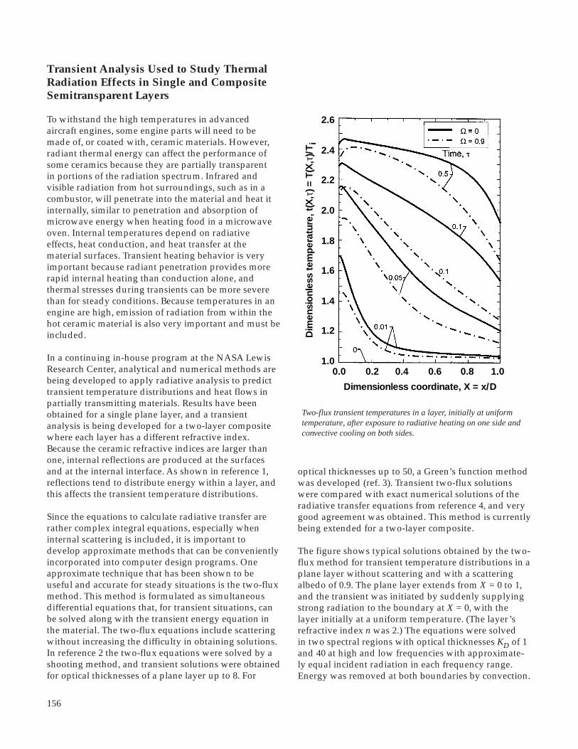
156
Transient Analysis Used to Study ThermalRadiation Effects in Single and CompositeSemitransparent Layers
To withstand the high temperatures in advancedaircraft engines, some engine parts will need to bemade of, or coated with, ceramic materials. However,radiant thermal energy can affect the performance ofsome ceramics because they are partially transparentin portions of the radiation spectrum. Infrared andvisible radiation from hot surroundings, such as in acombustor, will penetrate into the material and heat itinternally, similar to penetration and absorption ofmicrowave energy when heating food in a microwaveoven. Internal temperatures depend on radiativeeffects, heat conduction, and heat transfer at thematerial surfaces. Transient heating behavior is veryimportant because radiant penetration provides morerapid internal heating than conduction alone, andthermal stresses during transients can be more severethan for steady conditions. Because temperatures in anengine are high, emission of radiation from within thehot ceramic material is also very important and must beincluded.
In a continuing in-house program at the NASA LewisResearch Center, analytical and numerical methods arebeing developed to apply radiative analysis to predicttransient temperature distributions and heat flows inpartially transmitting materials. Results have beenobtained for a single plane layer, and a transientanalysis is being developed for a two-layer compositewhere each layer has a different refractive index.Because the ceramic refractive indices are larger thanone, internal reflections are produced at the surfacesand at the internal interface. As shown in reference 1,reflections tend to distribute energy within a layer, andthis affects the transient temperature distributions.
Since the equations to calculate radiative transfer arerather complex integral equations, especially wheninternal scattering is included, it is important todevelop approximate methods that can be convenientlyincorporated into computer design programs. Oneapproximate technique that has been shown to beuseful and accurate for steady situations is the two-fluxmethod. This method is formulated as simultaneousdifferential equations that, for transient situations, canbe solved along with the transient energy equation inthe material. The two-flux equations include scatteringwithout increasing the difficulty in obtaining solutions.In reference 2 the two-flux equations were solved by ashooting method, and transient solutions were obtainedfor optical thicknesses of a plane layer up to 8. For
Two-flux transient temperatures in a layer, initially at uniformtemperature, after exposure to radiative heating on one side andconvective cooling on both sides.
optical thicknesses up to 50, a Green’s function methodwas developed (ref. 3). Transient two-flux solutionswere compared with exact numerical solutions of theradiative transfer equations from reference 4, and verygood agreement was obtained. This method is currentlybeing extended for a two-layer composite.
The figure shows typical solutions obtained by the two-flux method for transient temperature distributions in aplane layer without scattering and with a scatteringalbedo of 0.9. The plane layer extends from X = 0 to 1,and the transient was initiated by suddenly supplyingstrong radiation to the boundary at X = 0, with thelayer initially at a uniform temperature. (The layer’srefractive index n was 2.) The equations were solvedin two spectral regions with optical thicknesses KD of 1and 40 at high and low frequencies with approximate-ly equal incident radiation in each frequency range.Energy was removed at both boundaries by convection.
2.6
2.4
2.2
2.0
1.8
1.6
1.4
1.2
1.0
Dim
ensi
onl
ess
tem
per
atur
e, t
(X,τ
) = T
(X,τ
)/T
i
0.0 0.2 0.4 0.6 0.8 1.0
Dimensionless coordinate, X = x/D

157
At the beginning of the transient, there was a rapidtemperature increase and a large temperature gradientnear X = 0 because of radiative heating. The tempera-tures were somewhat reduced when the scatteringalbedo was increased. Comparisons with results for anopaque layer showed that internal radiation has a largeeffect.
References
1. Siegel, R.: Refractive Index Effects on Transient Cooling of a Semitransparent Radiating Layer. J. Thermophys. Heat Transfer, vol. 9, no. 1, Jan.-Mar. 1995, pp. 55-62.
2. Siegel, R.: Two-Flux Method for Transient Radiative Heat Transfer in a Semitransparent Layer. Int. J. Heat Mass Transfer, to be published in 1996.
3. Siegel, R.: Two-Flux and Green’s Function Method for Transient Heat Transfer in a Semitransparent Layer. To be published in the Proceedings of the ICHMT International Symposium on Radiative Transfer, Kusadasi, Turkey, August 14-18, 1995.
4. Siegel, R.: Transient Heat Transfer in a Semitransparent Radiating Layer With Boundary Convection and Surface Reflections. Int. J. Heat Mass Transfer, vol. 39, no. 1, Jan. 1996, pp. 69-79.
Lewis contact: Dr. Robert Siegel, (216) 433-5831Headquarters program office: OA
New Theoretical Technique Developed forPredicting the Stability of Alloys
When alloys are being designed for aeronautical andother applications, a substantial experimental effort isnecessary to make incremental changes in the desiredalloy properties. A scheme to narrow the field to themost promising candidates would substantially reducethe high cost of this experimental screening.
Such a method for determining alloy properties, calledthe BFS (Bozzolo, Ferrante, and Smith) method, hasbeen developed at the NASA Lewis Research Center.This method was used to calculate the thermal stabilityand mechanical strength of 200 alloys of Ni3Al, with Cuand Au impurities forming ternary and quaternarycompounds. With recent advances in the method,almost any metallic impurity and crystal structurecan be addressed. In addition, thermal effects can beaddressed with Monte Carlo techniques. At present, an
experimental program is in progress to verify theseresults. The method identified a small number of themost promising candidates from the 200 alloys with thelargest negative heat of formation and the highest bulkmodulus. This calculation required only 5 min of CPUtime on a VAX computer.
It is clear that semi-empirical methods have achievedthe level of development and reliability to warrantexamining this new approach to the problem of alloydesign. The present work was meant to demonstrate,perhaps in a rather simple way, this power. This type ofapplication of atomistic simulation methods can narrowthe gap and improve the feedback between theoreticalpredictions and laboratory experimentation.
Bibliography
Bozzolo, G.; and Ferrante, J.: Bulk Properties of Ni3Al(Gamma Prime) with Cu and Au Additions. To be publishedin the Journal of Computer Aided Material Design, 1995.
Lewis contact: Dr. John Ferrante, (216) 433-6069Headquarters program office: OA
Lewis Research Academy

158
1995 R&TTechnology Transfer
CARES/LIFE Software Commercialization
The NASA Lewis Research Center has entered into aletter agreement with BIOSYM Technologies Inc. (nowmerged with Molecular Simulations Inc. (MSI)). Underthis agreement, NASA will provide a developmentalcopy of the CARES/LIFE computer program toBIOSYM for evaluation. This computer code predictsthe time-dependent reliability of a thermomechanicallyloaded component. BIOSYM will become familiar withCARES/LIFE, provide results of computations useful invalidating the code, evaluate it for potential commer-cialization, and submit suggestions for improvementsor extensions to the code or its documentation.
If BIOSYM/Molecular Simulations reaches a favorableevaluation of CARES/LIFE, NASA will enter into nego-tiations for a cooperative agreement with BIOSYM/Molecular Simulations to further develop the code—adding features such as a user-friendly interface andother improvements. This agreement would giveBIOSYM intellectual property rights in the modifiedcodes, which they could protect and then commercial-ize. NASA would provide BIOSYM with the NASA-developed source codes and would agree to cooperatewith BIOSYM in further developing the code. In return,NASA would receive certain use rights in the modifiedCARES/LIFE program.
Presently BIOSYM Technologies Inc. has been involvedwith integration issues concerning its merger withMolecular Simulations Inc., since both companies usedto compete in the computational chemistry market, andto some degree, in the materials market. Consequently,evaluation of the CARES/LIFE software is on hold for amonth or two while the merger is finalized. Theirinterest in CARES continues, however, and they expectto get back to the evaluation by early November 1995.
Find out more about Lewis’ technology transfer programsand BIOSYM/Molecular Simulations on the World WideWeb:http://www.lerc.nasa.gov/WWW/TU/techtran.htmhttp://www.biosym.com/
Lewis contacts: James E. Martz, (216) 433-5563(E-Mail: [email protected]), and Noel N.Nemeth, 433-3215Headquarters program office: OSAT
Combustion Technology Outreach
Lewis’ High Speed Research (HSR) Propulsion ProjectOffice initiated a targeted outreach effort to marketcombustion-related technologies developed at Lewisfor the next generation of supersonic civil transportvehicles. These combustion-related innovations rangefrom emissions measurement and reduction technolo-gies, to diagnostics, spray technologies, NOx and SOxreduction of burners, noise reduction, sensors, and fuel-injection technologies. The Ohio Aerospace Instituteand the Great Lakes Industrial Technology Centerjoined forces to assist Lewis’ HSR Office in thisoutreach activity.
From a database of thousands of nonaerospace firmsconsidered likely to be interested in Lewis’ combustionand emission-related technologies, the outreach teamselected 41 companies to contact. The selected com-panies represent oil-gas refineries, vehicle/partssuppliers, and manufacturers of residential furnaces,power turbines, nonautomobile engines, and dieselinternal combustion engines.
In May 1995, the outreach team held an initial roundof telephone interviews with representatives of the 41firms to determine common areas of interest, groundsfor potential collaboration, and preferred methods ofinteraction. As a result of these interviews, it wasdetermined that the greatest areas of interest involvedlowering NOx and SOx emissions; developing analysiscodes, materials, and instrumentation/diagnostics; andaddressing fuel injection, noise reduction, and mixingproblems.
The outreach team is now conducting follow-onteleconferences and face-to-face meetings to deter-mine areas of collaboration, assistance, and possibledevelopment of consortia.
For more information about Lewis’ research and technologytransfer programs, visit our sites on the World Wide Web:http://www.lerc.nasa.gov/WWW/Infosys/Development/HSR.htmlhttp://www.lerc.nasa.gov/WWW/TU/techtran.htmhttp://www.lerc.nasa.gov
Lewis contact: Katherine K. Martin, (216) 977-7122Headquarters program office: OA

159
Technology Transfer
A laser beam is used to study the Kirby G-4 fan in the Lewis Holography Test Lab. Fromleft to right are Kirby engineer Dennis Du, consultant Greg Stewart, and Kirby SeniorVice-President of Research and Development John Lackner. Seated is the Chief of Lewis’Propulsion Systems Branch, Edward Hronek.
Technology Transferred to the KirbyCompany
For more than 80 years now, the Kirby Company hasbeen recognized as a leader in the production anddevelopment of home-cleaning systems. Today, Kirby’sResearch and New Product Development Group hopesto evaluate advanced technologies and new conceptsthat could improve the performance, cost-effectiveness,and quality of its product. Areas of interest include fanand air-flow path improvements for performance; noisereduction; motor and electronic control; light-weight,cost-effective materials; and vibration analysis andcontrol.
Javier Resto and Edward Hronek, of NASA LewisResearch Center’s Propulsion Systems Branch,evaluated the structural and vibration characteristics
of the Kirby Model G-4 fan. Modes of vibration andresonance potential were evaluated in the HolographyTest Lab at Lewis. As a result of the Lewis tests androtor structural evaluation, Kirby engineers gained newinsights into their existing design, enabling them todevelop a more robust fan for use in their vacuumcleaners.
Find out more about Lewis’ technology transfer programson the World Wide Web:http://www.lerc.nasa.gov/WWW/TU/techtran.htm
Lewis contacts: James E. Martz, (216) 433-5563 (E-Mail:[email protected]), and Mark D. Bethea,(216) 433-8161 (E-Mail: [email protected])Headquarters program office: OSAT

160
Flow Visualization Proposed for VacuumCleaner Nozzle Designs
In 1995, the NASA Lewis Research Center and theKirby Company (a major vacuum cleaner company)began negotiations for a Space Act Agreement toconduct research, technology development, and testinginvolving the flow behavior of airborne particulate flowbehavior. Through these research efforts, we hope toidentify ways to improve suction, flow rate, and surfaceagitation characteristics of nozzles used in vacuumcleaner nozzles.
We plan to apply an advanced visualization technol-ogy, known as Stereoscopic Imaging Velocimetry (SIV)(ref. 1), to a Kirby G-4 vacuum cleaner. Resultant datawill be analyzed with a high-speed digital motionanalysis system. We also plan to evaluate alternativevacuum cleaner nozzle designs.
The overall goal of this project is to quantify bothvelocity fields and particle trajectories throughout thevacuum cleaner nozzle to optimize its “cleanability”—its ability to disturb and remove embedded dirt andother particulates from carpeting or hard surfaces.
Reference
1. Bethea, M.D.: Stereo Imaging Velocimetry. Research & Technology 1995. NASA TM-107111, 1996, pp. 44-45. (World Wide Web URL: http://www.lerc.nasa.gov/ RT1995/5000/5110B.htm)
Find out more about Lewis’ technology transfer programson the World Wide Web:http://www.lerc.nasa.gov/WWW/TU/techtran.htm
Lewis contacts: James E. Martz, (216) 433-5563 (E-Mail:[email protected]), and Mark D. Bethea,(216) 433-8161 (E-Mail: [email protected])Headquarters program office: OSAT
CommTech: The Commercial TechnologyConsultants Program
The Commercial Technology Consultants Program(CommTech), a nationwide Lewis initiative launched inMarch 1995, provides nonaerospace companies andNASA Lewis Research Center scientists and engineerswith a process for forming technical support relation-ships involving the commercialization of products orprocesses. The industries targeted in this effort span theenvironmental, surface transportation (land and sea),and biomedical sectors.
The first CommTech cycle consisted of the followingfour phases which will extend from fiscal 1995 to fiscal1997:
• Phase I—Participants Response and Selection• Phase II—Company Relationship Exploration• Phase III—Relationship Definition and Agreement• Phase IV—Agreement Implementation and Execution
In Phase I, 142 company-provided descriptions of long-term product- or process-related technology needs wereselected, filtered, compiled, and distributed to 1500Lewis scientists and engineers. Subsequently, 15 Lewisscientists and engineers applied as individuals and10 teams applied—bringing the total number of leadand nonlead Lewis scientific and engineering partici-pants to 50. At the end of Phase I, the lead participantsselected a total of 73 companies from 21 states forPhase II efforts. Over 80 percent of the selectedcompanies were small- or medium-sized, for-profitbusinesses.
During Phase II, Lewis’ lead participants initiatedone-on-one technical-level interactions with theselected companies. A shared budget of $230,000 wasmade available to the lead participants to fund limitedtechnology capability demonstrations for selectedcompanies that were unfamiliar with Lewis’ capa-bilities. The companies could then fund furtherinteractions, as desired. As CommTech participantsmake the transition from Phase II to Phase III, Lewis’lead participants will narrow their focus and each willselect one or more companies to support. As of October1995, 19 lead participants had identified companiesinterested in further interaction.
A press release about CommTech is available on the WorldWide Web:http://www.lerc.nasa.gov/WWW/PAO/pressrel/95_41.htm
Lewis contact: Gary A.P. Horsham, (216) 433-8316Headquarters program office: OSAT

161
NASA Headquarters Program Offices
OA Office of Aeronautics
HPCCO High Performance Computing & Communications Office
OLMSA Office of Life & Microgravity Sciences & Applications
MSAD Microgravity Science & Applications Division
OSAT Office of Space Access and Technology
STD Space Transportation Division
SSD Space Systems Division
OSC Office of Space Communications
OSMA Office of Safety and Mission Assurance
OSS Office of Space Science
SSED Solar System Exploration Division
SPD Space Physics Division

162
Dever, Joyce A. 107aDiCarlo, Dr. James A. 50Dittmar, Dr. James H. 33
EEllis, Dr. David L. 47
FFerguson, Dr. Dale C. 100, 101, 102Fernandez-Pello, Prof. A. Carlos 144Ferrante, Dr. John 157Forkapa, Mark J. 108Foss, Dr. Judith K. 16
GGaier, Dr. James R. 107bGarg, Dr. Anita 45Georgiadis, Nicholas J. 27bGhosn, Dr. Louis J. 80Ginty, Carol A. 43Gray, Dr. Hugh R. 43Greenberg, Paul S. 134Griffin, Dr. Devon W. 134Guasp, Edwin 96Gyekenyesi, Dr. John P. 78b
HHalford, Dr. Gary R. 62, 70Hamley, John A. 90Handschuh, Dr. Robert F. 26Hathaway, Dr. Michael D. 14Haugland, Dr. Edward J. 121Hegde, Dr. Uday 136Heidelberg, Larry J. 34Heidger, Dr. Susan L. 52Hendricks, J. Lynne 78aHerbell, Dr. Thomas P. 48
AAbel, Dr. Phillip B. 51Abdul-Aziz, Dr. Ali 68Acevedo, Julio C. 149Acosta, Dr. Roberto J. 132Adamczyk, Dr. John J. 155aAddy, Gene 20Arnold, Dr. Steven M. 65, 67Ashpis, Dr. David E. 13
BBakhle, Milind A. 75Banks, Bruce A. 108Barnett, Alan R. 154Becks, Edward A. 36Bethea, Mark D. 44, 159, 160aBexten, Ronald L. 124Bhasin, Dr. Kul B. 117Bodis, James R. 78aBonacuse, Peter J. 69Bond, Thomas H. 21Britton, Randall K. 21Brown, Dr. Gerald V. 76
CCanacci, Victor A. 22Castelli, Michael G. 72, 74Chang, Dr. Clarence T. 15Chiaramonte, Dr. Fran 142Chock, Ricaurte 103Chuang, Dr. Kathy C. 55Cole, Gary L. 12Curtis, Henry B. 95
DDeBonis, James R. 30De Groh, Kim K. 106, 111De Groot, Dr. Wilhelmus A. 88DeLaat, John C. 9DeLombard, Richard 149
Index of Authors and Contacts
Both authors and contacts are listed in this index. However, only primary contacts arereferenced in the actual articles. Articles for these authors and contacts start on the pagenumbers following the names. When two articles start on the same page, the first articleis indicated by the letter "a" after the number and the second article by a "b."

163
Hickman, J. Mark 150, 151Hill, Myron E. 139Hillard, Dr. Barry 100Hollansworth, James E. 116Hopkins, Dale A. 59, 60bHorsham, Gary A.P. 160bHronek, Edward J. 159Hughes, William O. 153Hultgren, Dr. Lennart S. 155bHung, Dr. Ching-Cheh 109Hunter, Gary W. 5Hurwitz, Dr. Frances I. 57
IIvancic, William D. 125
JJacqmin, Dr. David A. 113Jacobson, Dr. Nathan S. 58Jankovsky, Robert S. 87Janosik, Lesley A. 78bJavidi, Sina 130b, 132Jaworske, Dr. Donald A. 110, 111, 112aJeracki, Robert J. 33Johns, Albert L. 27aJones, Scott M. 2
KKalluri, Dr. Sreeramesh 68, 69, 70Kascak, Albert F. 76Kerczewski, Robert J. 127a, 127bKlem, Mark D. 81Kolecki, Joseph C. 102Koudelka, John M. 144, 145Krainsky, Dr. Isay L. 122aKrantz, Timothy L. 25
LLam, David W. 29Larkin, Dr. David J. 4Lawrence, Dr. Charles 40Lee, Kuan S. 154Lei, Dr. Jih-Fen 3, 72Lepicovsky, Dr. Jan 31Lerch, Bradley A. 61, 62Lewandowski, Beth 41Lewicki, Dr. David G. 23, 26
Lopez, Isaac 38Ludwiczak, Damian R. 154Lyons, Dr. Valerie J. 19
MMakel, Darby 5Malarik, Diane C. 141Manning, Dr. Robert M. 129a, 129b, 130aMartin, Donald F. 141Martin, Katherine K. 78a, 158bMartz, James E. 158a, 159, 160aMcCartney, Timothy P. 37McKissock, Barbara I. 94McNelis, Anne M. 153Meador, Dr. Mary Ann B. 57Meador, Dr. Michael A. 55, 56Merte, Dr. Herman 142Meyer, Michael L. 83Miller, Dean R. 20Miller, Fletcher J. 137Millis, Marc. G. 92Mitchell, Kenneth 132Miyoshi, Dr. Kazuhisa 52Morales, Dr. Wilfredo 54Myers, Dr. Roger M. 91
NNakamura, Dan 130bNeiner, George H. 27aNemeth, Noel N. 78a, 78b, 158aNeudeck, Dr. Philip G. 4Neumann, Eric S. 146Niedzwiecki, Richard W. 19Noebe, Ronald D. 61
OOlson, Sandra L. 133Oswald, Fred B. 24Otero, Angel M. 142
PPalaszewski, Bryan A. 85, 86Patnaik, Dr. Surya N. 59Paxson, Daniel E. 8Pereira, Dr. J. Michael 60aPiszczor, Michael F. 94, 95Potapczuk, Dr. Mark G. 22

164
Powell, J. Anthony 4, 51Powers, Lynn M. 78bProkopius, Paul R. 97
QQuinn, Todd 123Quintana, Jorge A. 123
RRaj, Dr. Sai V. 45Rapp, Prof. Robert A. 58Raquet, Dr. Charles A. 122b, 130bReddy, Dr. D.R. 10, 11Reehorst, Andrew L. 22Reinhart, Richard 130bRenz, David D. 98Ross, Dr. Howard D. 136, 137Roth, Dr. Don J. 78aRutledge, Sharon K. 105
SSaiyed, Naseem H. 35Saravanos, Dimitris A. 60bSchneider, Dr. Steven J. 89Shaltens, Richard K. 114Siegel, Dr. Robert 156Singh, Dr. Mrityunjay 49Smalley, Robert R. 36, 37Smith, Timothy D. 87Soeder, James F. 99Sohn, Philip Y. 130bSoni, Nitin J. 125Sotomayor, Jorge L. 7Steffen, Christopher J., Jr. 16Stefko, George L. 75Steinetz, Dr. Bruce M. 77Stevens, Grady H. 120Stevenson, Steven M. 150Stocker, Dennis P. 136Strazisar, Dr. Anthony J. 14Stueber, Thomas J. 112b
TTaylor, Linda M. 98Telesman, Jack 80Thomas, Scott R. 18Tolbert, Carol M. 113
VValco, Dr. Mark J. 17Vannucci, Raymond D. 56Veres, Joseph P. 39
WWadel, Mary F. 83Wagar, William O. 148Wald, Lawrence W. 113Walker, James F. 84Warshay, Dr. Marvin 97Weislogel, Mark M. 140Welch, Dr. Gerard E. 32Wernet, Dr. Mark P. 6Whalen, Mike 78aWhyte, Wayne A., Jr. 117, 119Widrick, Timothy W. 154Wiedenmannott, Barbara E. 1Wilson, Dr. Jack 32Wolter, John D. 28Woo, Dr. Myeung J. 101Worthem, Dr. Dennis W. 64Wright, David L. 132
ZZaman, Dr. Khairul 16

166
March 1996
NASA TM–107111
E–10017
None
This publication is available from the NASA Center for Aerospace Information, (301) 621–0390.
178
A09
Research & Technology 1995
Aeronautics; Aerospace engineering; Space flight; Space power; Materials; Structures;Electronics; Space experiments; Technology transfer
Responsible person, Walter S. Kim, organization code 9400, (216) 433–3742.
Unclassified -UnlimitedSubject Categories 01 and 31
This report selectively summarizes the NASA Lewis Research Center’s research and technology accomplishments forfiscal year 1995. It comprises over 150 short articles submitted by the staff members of the technical directorates. Thereport is organized into six major sections: aeronautics, aerospace technology, space flight systems, engineering support,Lewis Research Academy, and technology transfer. A table of contents, an author index, and a list of NASA Headquartersprogram offices have been included to assist the reader in finding articles of special interest. This report is not intended tobe a comprehensive summary of all research and technology work done over the past fiscal year. Most of the work isreported in Lewis-published technical reports, journal articles, and presentations prepared by Lewis staff members andcontractors (for abstracts of these Lewis-authored reports, visit the Lewis Technical Report Server (LeTRS) on the WorldWide Web—http://letrs.lerc.nasa.gov/LeTRS/). In addition, university grants have enabled faculty members and graduatestudents to engage in sponsored research that is reported at technical meetings or in journal articles. For each article in thisreport, a Lewis contact person has been identified, and where possible, reference documents are listed so that additionalinformation can be easily obtained. The diversity of topics attests to the breadth of research and technology being pursuedand to the skill mix of the staff that makes it possible. For more information about Lewis’ research, visit us on the WorldWide Web—http://www.lerc.nasa.gov.
REPORT DOCUMENTATION PAGE
2. REPORT DATE
19. SECURITY CLASSIFICATION OF ABSTRACT
18. SECURITY CLASSIFICATION OF THIS PAGE
Public reporting burden for this collection of information is estimated to average 1 hour per response, including the time for reviewing instructions, searching existing data sources,gathering and maintaining the data needed, and completing and reviewing the collection of information. Send comments regarding this burden estimate or any other aspect of thiscollection of information, including suggestions for reducing this burden, to Washington Headquarters Services, Directorate for Information Operations and Reports, 1215 JeffersonDavis Highway, Suite 1204, Arlington, VA 22202-4302, and to the Office of Management and Budget, Paperwork Reduction Project (0704-0188), Washington, DC 20503.
NSN 7540-01-280-5500 Standard Form 298 (Rev. 2-89)Prescribed by ANSI Std. Z39-18298-102
Form Approved
OMB No. 0704-0188
12b. DISTRIBUTION CODE
10. SPONSORING/MONITORING AGENCY REPORT NUMBER
8. PERFORMING ORGANIZATION REPORT NUMBER
5. FUNDING NUMBERS
3. REPORT TYPE AND DATES COVERED
4. TITLE AND SUBTITLE
6. AUTHOR(S)
7. PERFORMING ORGANIZATION NAME(S) AND ADDRESS(ES)
9. SPONSORING/MONITORING AGENCY NAME(S) AND ADDRESS(ES)
11. SUPPLEMENTARY NOTES
12a. DISTRIBUTION/AVAILABILITY STATEMENT
14. SUBJECT TERMS
17. SECURITY CLASSIFICATION OF REPORT
16. PRICE CODE
15. NUMBER OF PAGES
20. LIMITATION OF ABSTRACT
Unclassified Unclassified
Technical Memorandum
Unclassified
National Aeronautics and Space AdministrationLewis Research CenterCleveland, Ohio 44135–3191
National Aeronautics and Space AdministrationWashington, DC 20546–0001
1. AGENCY USE ONLY (Leave blank)
13. ABSTRACT (Maximum 200 words)