rts pocket guide pt i - somfyservice.somfy.com/downloads/nam_pro/2011_rts_pocket_guide_low.pdf ·...
TRANSCRIPT

RTS Pocket Programming Guide

Table of Contents
P.2 How Does RTS Work?
Transmitters
P. Individual ControlP.21/22 Group ControlP.23/24 Individual & Group Control
19/20
P.15 Sunis Indoor WireFree™ SensorP.16 Thermo Sunis Indoor WireFree™ SensorP.17 Eolis 3D WireFree™ Wind SensorP.18 Outdoor Sunis WireFree™ Sensor
Receiver
Understanding Control Options
P.5 Telis Hand-Held RemoteP.6 Telis Soliris Hand-Held RemoteP.7 Telis Modulis Hand-Held RemoteP.8 Telis 16 Channel Hand-Held RemoteP.9 DecoFlex Wireless Wall SwitchP.10 DecoFlex Table Top AccessoryP.11 Telis 6 Channel Chronis RTS Hand-Held Timer
P.12 Outdoor Lighting Receiver P.12 Outdoor Universal Receiver
P.13 Universal RTS Interface (URTSI)
P.14 RTS Repeater
P.3/4 Identify RTS Control Options
P.25/26 Product Application & Motor Compatibility Chart
Interface
Repeater
Sensors

P.31-36
Quick Programming Guides
P.27 P.27 Tilt WireFree™
P.27 LT30 Roll Up WireFree™
P.28 ST30 Sonesse™ 30P.28 ST40 Sonesse™ 40P.28 Altus 40P.29 ST50 Sonesse™ 50P.29 Altus 50P.29 LT50 RTS CMOP.30 Sunea RTS CMOP.30 Altus 60P.30 Glydea™ 35P.30 Glydea™ 60
CT32 Cord Lift WireFree™
RTS Motor Range
CT32 Cord Lift WireFree™
LT30 Roll Up WireFree™
ST30 Sonesse™ 30ST40 Sonesse™ 40Altus 40ST50 Sonesse™ 50Altus 50Altus 60
P.37-42P.43-46P.47-50P.51-54P.55P.56P.57P.58-61P.62-67P.68-69P.70P.71/72P.73-88
Tilt WireFree™
LT RTS CMOSunea RTS CMOGlydea™
Outdoor Universal Receiver RTSOutdoor Lighting Receiver RTSUniversal RTS Interface (URTSI)Sunis Indoor WireFree™ SensorThermo Sunis Indoor WireFree™ SensorEolis 3D WireFree™ Wind SensorOutdoor Sunis WireFree™ SensorTelis 16 RTSTelis 6 Chronis RTS
P.89 Troubleshooting

Home Motion by Somfy
We’ve developed a brand expression that emphasizes the
centerpiece of consumers’ lives, the home. It also represents
Somfy’s mission, bringing homes to life by creating movement
for all openings and allowing consumers to enjoy life’s daily
pleasures for a better quality of life.
1

How Does It Work?
Available with hand-held remotes, wireless wall switches, table top controls and timers
Simply press a button on a remote control or wall switch
and window coverings move with ease. There is no need
to point or aim the transmitter at the covering because ®Radio Technology Somfy (RTS) is omni-directional.
And just like a garage door opener, the radio waves travel
through walls.
No need to aim the control at the motorized window covering, theradio signal travels through walls similar to a garage door opener
Offers a range of 65 ft. for easy operation
No extra wires are needed
Provides the ability to control all motorized window coverings individually and/or by group with one control
Flexibility to change user preferences with simplified programming
Available in single and multi-channel versions
Over 10 million installations worldwide
Secure operation with a rolling code reducing interference with other radio products
Offers simplified integration with home automation systems
2

Identify RTS Control Options
Hand-Held Remotes
Users can control motorized window coverings by pressing
a button or rolling a scroll wheel on a variety of hand-held
RTS remotes.
Wireless Wall Switches
Users can easily control their motorized window coverings
when entering or exiting a room with DecoFlex RTS Wall
Switches.
Table Top Remotes
Users can control their motorized window coverings with
the versatile DecoFlex Table Top remote.
Transmitters
Receivers
Users can adjust window coverings powered by standard
motors, as well as operate incandescent and halogen lights
and other outdoor devices by using a particular receiver.
3

Users can set sensors to automatically adjust motorized
window coverings in accordance to the amount of sunlight
received, temperature recorded, as well as the speed and
direction of wind.
Repeater
Sensors
Users can convert Infrared, RS232, and RS485 protocol
into RTS, allowing for 3rd party control of motorized
window coverings.
Users can extend the distance of motorized window
covering control.
Interface
4

UP Button
The “my” button acts as a stop button when the windowcovering is in motion. When the window covering is stationary,the “my” button brings it to theprogrammed favorite position.
DOWN Button
Channel LEDAll 4 lights will illuminate when fifth channel is activated.
Channel Selector Button
Telis 4 RTS Hand-Held Remote
shown in Pure finishTelis 1 RTS also available
Telis Hand-Held Remote
Features
Also available in multiple finishes:
Silver Lounge Patio
Channel 1 selectedChannel 2 selectedChannel 3 selectedChannel 4 selectedChannel 5 selected
Programming Button(recessed)
Back of Remote view
5
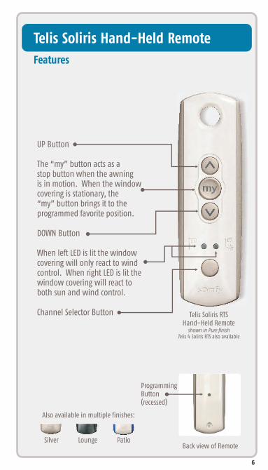
UP Button
The “my” button acts as a stop button when the awningis in motion. When the window covering is stationary, the “my” button brings it to the programmed favorite position.
DOWN Button
When left LED is lit the windowcovering will only react to windcontrol. When right LED is lit thewindow covering will react toboth sun and wind control.
Channel Selector Button Telis Soliris RTS Hand-Held Remote
shown in Pure finishTelis 4 Soliris RTS also available
Telis Soliris Hand-Held Remote
Features
Programming Button(recessed)
Back of Remote view
Also available in multiple finishes:
Silver Lounge Patio
6

Telis 4 Modulis RTS Hand-Held Remote
shown in Lounge finishTelis 1 Modulis RTS also available
Telis Hand-Held RemoteModulis
Features
Programming Button(recessed)
Channel 1 selectedChannel 2 selectedChannel 3 selectedChannel 4 selectedChannel 5 selected
Back of Remote view
Available in multiple finishes:
Silver Pure
Open/Close buttons
Scroll wheel for incremental tilt controlof horizontal blinds and sheer horizontal products.
”my” button for a favorite blind position
LED identifies active channel
Channel Selector Button
7
Telis 16 Channel RTS Hand-Held Remote
shown in Pure finish
Telis 16 Channel Hand-Held Remote
Features
Programming Button(recessed)
Back of Remote view
Also available in Silver finish
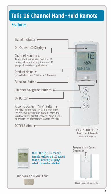
Signal Indicator
On-Screen LCD Display
Channel Number16 channels can be used to control 16individual motorized applications or 16groups of motorized applications.
Product Name(up to 8 characters: 7 Letters + 1 Number)
Selection Button
Channel Navigation Buttons
UP Button
Favorite position “my” ButtonThe “my” button acts as a stop button when the window covering is in motion. When the window covering is stationary, the “my” button brings it to the programmed favorite position.
DOWN Button
NOTE: The Telis 16 channel remote features an LCD screen that numerically displays what channel is selected.
8

5 Channel Button DecoFlex WireFree™ RTS Wall Switch shown in White Finish
ProgrammingButton(recessed)
Also available in multiple finishes and various
channel button versions:
DecoFlex Wireless Wall Switch
Features
Ivory Black
9
For a complete list of available pre-printed buttonsplease go to www.somfystore.com and search for “buttons”.
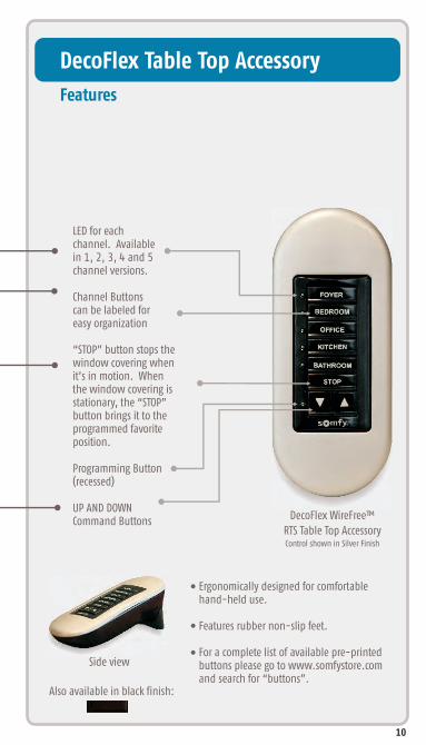
LED for each channel. Available in 1, 2, 3, 4 and 5channel versions.
Channel Buttons can be labeled for easy organization
“STOP” button stops the window covering when it’s in motion. When the window covering is stationary, the “STOP”button brings it to the programmed favorite position.
Programming Button(recessed)
UP AND DOWN Command Buttons DecoFlex WireFree™
RTS Table Top AccessoryControl shown in Silver Finish
DecoFlex Table Top Accessory
Features
Side view
Ergonomically designed for comfortable hand-held use.
Features rubber non-slip feet.
For a complete list of available pre-printed buttons please go to www.somfystore.com and search for “buttons”.
10
Also available in black finish:

Telis 6 Channel Hand-Held TimerChronis RTS
Features
Telis 6 Channel RTS Hand-Held Remote
shown in Silver finish
Programming Button(recessed)
Back of Remote view
Also available in Pure finish:
Signal Indicator
On-Screen LCD Display
Selection Button
Channel Navigation Buttons
UP Button
Favorite position “my” ButtonThe “my” button acts as a stop button when the window covering is in motion. When the window covering is stationary, the “my” button brings it to the programmed favorite position.
DOWN Button
11

Outdoor Lighting Receiver
Features
*For programming instructions please go to P. 56
Control patio or deck lights with the same remote used for the awning.
Controls incandescent, halogen lights or any outdoor device up to 500W.
™Fully compatible with the Telis RTS range of transmitters and the DecoFlex WireFree™ RTS wall switches.
Weatherproof cover with watertight strain-relief fittings for wires
Universal RTS Receiver
Features
*For programming instructions please go to P. 56
Provides RTS capability to Somfy’s standard motors.
Can be used as a stand-alone RTS control or with RTS sensors.
Two user-defined intermediate positions can be programmed.
Weatherproof cover with watertight strain-relief fittings for wires
MOTOR
R
NEUTRALGROUND
SEQUENCE BUTTON
UP
DOWN
MTR COM
NEUT
HOT
HOT
HOT
NEUT
GROUND
PROGRAMMING BUTTON
PROGRAMMING LED
12
500 WATTS MAX.
NEUTRAL
GROUND
500W Max Lighting Output
NEUT
HOT
HOT
HOT
NEUT
GROUND
PROGRAMMING BUTTON
PROGRAMMING LED
SEQUENTIAL CONTROL BUTTON
LAMP

Universal RTS Interface (URTSI)
Features
Antenna
IR Sensor Port
RS232 or RS485 Input
Allows user to convert infrared, RS232 and RS485 ®protocol into Radio Technology Somfy (RTS) to allow
for third party control.
Offers 16 channels.
Compatible with full range of RTS motors.
With its compact and sleek design, the URSTI can be housed in a discrete location.
9 Volt DC(power supplyincluded)
UPSTOPDOWNProgram ButtonChannel SelectorRTS Transmission LED
13
Rs485 Expansion

RTS Repeater
Features
Antenna
Indicator Light
Simply plugs into any 120V AC electrical outlet.
No programming required.
Should be placed approximately halfway between the transmitting device such as a Telis hand-held remote and the receiving device, the motor.
Solves the challenge of transmitting the signal in particularly large rooms or areas.
Range: 60 ft.
The RTS Repeater receives the signal from a Telis RTS remote or DecoFlex WireFree wall switch or similar device and re-transmits the signal to an RTS compatible motor or receiver.
™
14

Sunis Indoor WireFree™ Sensor
Features
LED Indicator
ON/OFF Selector Switch
Control Setting Panel
Programming Button
Mode Button
Front view with cover installed
Back View
Front view withcover removed
Lightsensing eye
The Sunis Indoor Sensor can beprogrammed to automatically adjust window coverings in accordance to sunlight threshold settings.
window sill mount
window mount
Suction cup for mountingon window sillor window
Sun SensitivityThresholdAdjustment
15
Thermo Sunis Indoor WireFree Sensor™
Features
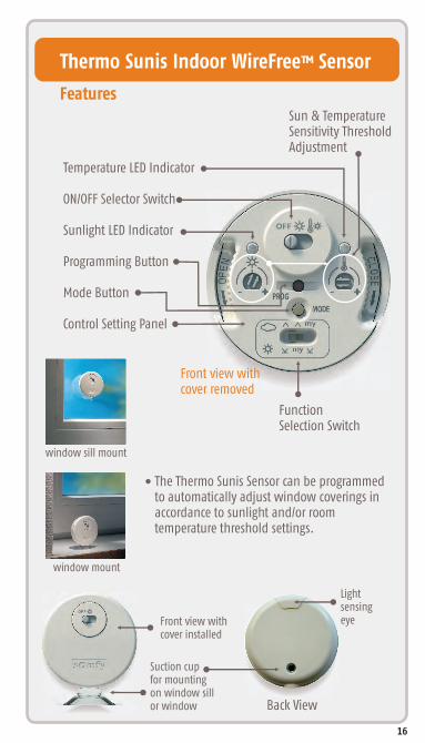
Temperature LED Indicator
ON/OFF Selector Switch
Sunlight LED Indicator
Programming Button
Mode Button
Control Setting Panel
Front view with cover installed
Back View
Lightsensing eye
Front view withcover removed
window sill mount
window mount
The Thermo Sunis Sensor can be programmed to automatically adjust window coverings in accordance to sunlight and/or room temperature threshold settings.
Function Selection Switch
Sun & TemperatureSensitivity ThresholdAdjustment
Suction cup for mountingon window sillor window
16

Eolis 3D WireFree Wind Sensor ™
Features
Installed discreetly on the end of the front bar.
Easy wireless installation.
Automatically retracts the awning with the detectionof wind generated movements.
Easy to program.
Maintenance free, long life batteries.
Programming Button
SensitivityAdjustmentButton
Mounting Plate
17

Outdoor Sunis WireFree Sensor™
Features
Solar powered sun sensor.
Easy wireless installation.
Automatically adjusts shutters, awnings and window coveringswhen the programmed sunlight threshold is reached.
Compact design allows for discreet mounting.
Telis Soliris RTS remote recommended to controlON/OFF function.
Light sensing eye
Front View
ModeButton
ProgramButton
LED
Back View
18
Sun level/Mode Indicator

Channel 1:
Individual Control of SHADE 1
Channel 2:
Individual Control of SHADE 2
Channel 3:
Individual Control of SHADE 3
Channel 4:
Individual Control of SHADE 4
*Channel 5:
Individual Control of DRAPERY
Telis 4 RTSHand-Held Remote
Understanding Control Options:
*Fifth channel is activated when all4 LEDs illuminate
The Telis 16 channel remote features an LCD screen that numerically displays which channel is selected.
Applies to all Telis Hand-Held remotes.
19

DecoFlex WireFree™ RTS5 Channel Button Version
Individual Control
20
For a complete list of available pre-printed buttonsplease go to www.somfystore.com and search for “buttons”.

Channel 1:
Group Control of window coverings in FOYER
Channel 2:
Group Control of blinds in BEDROOM
Channel 3:
Group Control of window coverings in OFFICE
Channel 4:
Group Control of window coverings in KITCHEN
*Channel 5:
Group Control of window coverings inBATHROOM
The Telis 16 channel remote features an LCD screen that numerically displays which channel is selected.
*Fifth channel is activated when all4 LEDs illuminate
Telis 4 Modulis RTSHand-Held Remote
Understanding Control Options:
Applies to all Telis Hand-Held remotes.
21

DecoFlex WireFree™
RTS Table Top Accessory
Group Control
22
For a complete list of available pre-printed buttonsplease go to www.somfystore.com and search for “buttons”.
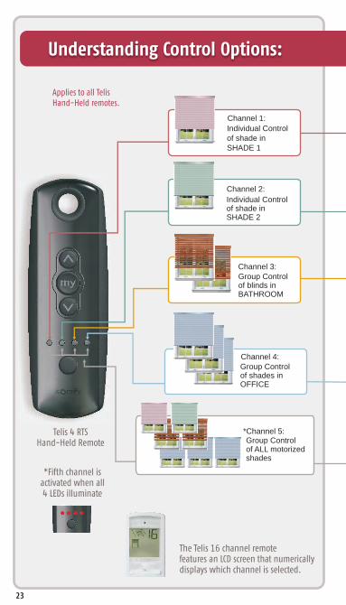
Channel 1:
Individual Control of shade in SHADE 1
Channel 2:
Individual Control of shade in SHADE 2
Channel 3: Group Control of blinds in BATHROOM
Channel 4: Group Control of shades in OFFICE
*Channel 5: Group Control of ALL motorized shades
The Telis 16 channel remote features an LCD screen that numerically displays which channel is selected.
*Fifth channel is activated when all4 LEDs illuminate
Telis 4 RTSHand-Held Remote
Understanding Control Options:
Applies to all Telis Hand-Held remotes.
23

DecoFlex WireFree™ RTS5 Channel Button Version
Individual and Group Control
24
For a complete list of available pre-printed buttonsplease go to www.somfystore.com and search for “buttons”.

LT30™ROLL UP WIREFREE P
ALTUS 60
SUNEA RTS CMO
LT50RTS CMO
ALTUS 50
ST50 ™SONESSE 50
ALTUS 40
ST40™SONESSE 40
™GLYDEA 35
ST30™SONESSE 30
TILT ™WIREFREE
CT32™CORD LIFT WIREFREE
SHEER HORIZONTAL
SHADE
Product Application &
™GLYDEA 60
12 V
12 V
12 V
24 V
110 V
110 V
110 V
110 V
110 V
110 V
110 V
110 V
110 V
ROLLER SHADEROMAN/WOVEN
SHADE2” HORIZONTAL
BLIND
PP
PPPPPPPPPPPPPP
PP
P
P
25

Motor Compatibility Chart
AWNINGSROLLINGSHUTTERDRAPERIES
PLEATED/CELLULAR SHADES
P.27
MOT
OR
DET
AILS
PAG
E
EXTERIORSOLAR SCREENS
P.27
P.27
P.28
P.28
P.28
P.29
P.29
P.29
P.30
P.30
P.30
P
P
P
P
PPP
PPP
PPPPPPP
P.30
26
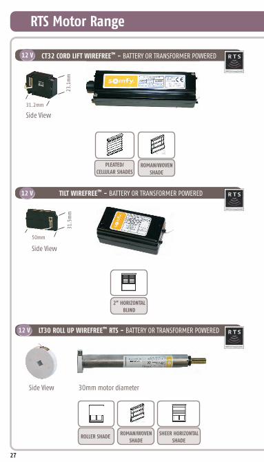
RTS Motor Range
™CT32 CORD LIFT WIREFREE - BATTERY OR TRANSFORMER POWERED12 V
12 V ™TILT WIREFREE - BATTERY OR TRANSFORMER POWERED
™LT30 ROLL UP WIREFREE RTS - BATTERY OR TRANSFORMER POWERED12 V
Side View
SHEER HORIZONTAL
SHADE
ROMAN/WOVEN
SHADEROLLER SHADE
2” HORIZONTAL
BLIND
PLEATED/
CELLULAR SHADESROMAN/WOVEN
SHADE
Side View
Side View
27
31.2mm
23.1
mm
50mm
31.5
mm
30mm motor diameter
Side View
SHEER HORIZONTAL
SHADEROLLER SHADE
ROMAN/WOVEN
SHADE
PLEATED/
CELLULAR SHADES2” HORIZONTAL
SHADE
Side View
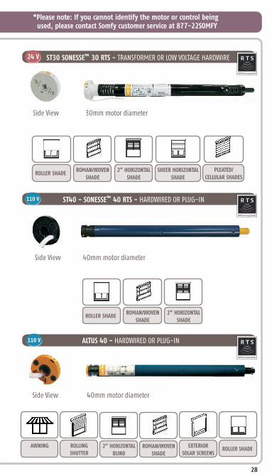
*Please note: If you cannot identify the motor or control being used, please contact Somfy customer service at 877-22SOMFY
™ST30 SONESSE 30 RTS - TRANSFORMER OR LOW VOLTAGE HARDWIRE24 V
ALTUS 40 - HARDWIRED OR PLUG-IN
ST40 - SONESSE 40 RTS - HARDWIRED OR PLUG-IN™110 V
ROLLER SHADEROMAN/WOVEN
SHADE
2” HORIZONTAL
SHADE
Side View
110 V
AWNING ROLLING
SHUTTER2” HORIZONTAL
BLINDROMAN/WOVEN
SHADE
EXTERIOR
SOLAR SCREENSROLLER SHADE
28
30mm motor diameter
40mm motor diameter
40mm motor diameter

™ST50 SONESSE 50 RTS - HARDWIRED OR PLUG-IN110 V
ROLLER SHADEROMAN/WOVEN
SHADE
2” HORIZONTAL
SHADE
Side View
RTS Motor Range
ALTUS 50 - HARDWIRED OR PLUG-IN
LT50 RTS CMO - HARDWIRED OR PLUG-IN
Side View
110 V
110 V
AWNINGROLLING
SHUTTER
EXTERIOR
SOLAR SCREENS
AWNINGROLLING
SHUTTER2” HORIZONTAL
BLINDROMAN/WOVEN
SHADE
EXTERIOR
SOLAR SCREENSROLLER SHADE
Side View
29
50mm motor diameter
50mm motor diameter
50mm motor diameter

*Please note: If you cannot identify the motor or control being used, please contact Somfy customer service at 877-22SOMFY
SUNEA - HARDWIRED OR PLUG-IN
GLYDEA 35 RTS - PLUG-IN™
ALTUS 60 - HARDWIRED OR PLUG-IN
110 V
110 V
GLYDEA 60 RTS - PLUG-IN™110 V
AWNINGEXTERIOR
SOLAR SCREENS
110 V
DRAPERY
AWNINGROLLING
SHUTTER
DRAPERY
Side View
Side View
Side View
30
50mm motor diameter
Side View 60mm motor diameter
95mm
53mm
95mm
53mm

BEFORE YOU BEGINMotors are shipped in FACTORY MODE without limit settings and transmitter Id’s. Power must ONLY be connected to current window covering being programmed. All other window coverings must be disconnected from their respective power while programming.
FACTORY MODE
With the motor installed in window covering, connect power to themotor (120V AC, or 12V DC or 24V DC transformer or 12V battery wand).
Initiate ProgrammingOn the transmitter, press and hold both the UP and DOWN simultaneously until the window covering jogs. A jog is a brief up and down or in and out motion. In PROGRAMMING MODE, the window covering will move only when the UP or DOWN is held (or momentary fashion).
CT32 CORD LIFT WIREFREE LT30 ROLL UP WIREFREE ST30 SONESSE 30 ST40 SONESSE 40
QUICK PROGRAMMING GUIDE FOR THE FOLLOWING RTS MOTORS
Note - If motor is 120V AC hardwired and cannot be disconnected, please contact an electrician prior to calling Somfy customer service for assistance. !
ALTUS 40 ST50 SONESSE 50 ALTUS 50 ALTUS 60
While programming, window covering should not be inactive for longer than 2 minutes or motor will exit PROGRAMMING MODE.
Connect Power To Motor
PROGRAMMING MODE
!
31

Set the Upper LimitSTEP 1: Bring the window covering to desired UPPER limit stop point with the UP button. Press and hold both (STOP) and DOWN simultaneously until the application starts to move, then release. If the window covering stops when the buttons are released, take it back to the UPPER limit and repeat. Stop the motor when reaching the desired LOWER limit. You can adjust by pressing UP or DOWN after stopping the motor.
my
Set the Lower Limit STEP 2: Press and hold both (STOP) and UP simultaneously until the application starts to move, then release. The window covering will stop at the UPPER limit that was previously set.
my
Check the Direction of operation
If hand-held transmitter direction is not properly programmed, Eolis/Soliris RTS sensor will not function in the manner it was intended. Damage to motorized window covering and injury may occur as a result.
Check DirectionsPress and hold UP or DOWN . When pressing DOWN product should go down or out. If window covering does not correspond with UP or DOWN you must REVERSE the output direction. To reverse output direction, simply press & hold the (STOP) until the window covering jogs. Output direction should now correspond.
my
Setting Limits
Confirm Limit SettingsSTEP 3: Press and hold (STOP) until the window covering jogs to confirm the limit settings. A jog is a brief up and down motion.
my
!In case of problems with setting of limits during PROGRAMMING MODE, turn the power off to the motor for 2 seconds and then back on to resetthe motor. Please return to PROGRAMMING MODE to initiate programmingprocess.
QUICK PROGRAMMING GUIDE FOR RTS MOTORS
During installation, it is mandatory to test and verify the motorized window covering operates in accordance to the commands from hand-held transmitter.
Installer or user must verify the following Hand-Held transmitter (DOWN) command:Awning Installations: = awning moves outward or extends.Shade/Shutter Installations: = shade/shutter moves downward or closes.
32

STEP 3: Press and hold (STOP) until the window covering jogs, to confirm new limit.
STEP 2: Press and hold both UP and DOWN simultaneously until the window covering jogs. Adjust to a new LOWER limit position.
To Change the Lower Limit:STEP 1: Press DOWN to send the window covering to it’s current LOWER Limit.
my
STEP 2: Press and hold both UP and DOWN simultaneously until the window covering jogs. Adjust to a new UPPER limit position.
STEP 3: Press and hold (STOP) until the window covering jogs, to confirm new limit.
To Change the Upper Limit:STEP 1: Press UP to send the window covering to it’s current UPPER Limit.
my
Setting Intermediate Preferred “MY” Position
Press the or to operate window covering. At the desired intermediate “MY” position press (STOP) briefly to stop the window covering.
Once the desired “MY” position is reached, press and hold (STOP) until the window covering jogs. The “MY” position is now added to memory.
my
my
USER MODE
Programming CompletedStep 4: Press and hold the PROGRAMMING BUTTON on the back of the transmitter until the window covering jogs. The window covering is now in USER MODE. In USER MODE, the window covering will operate with a brief PRESS on UP or DOWN (or maintained fashion).
Adjusting the Limits in User Mode
QUICK PROGRAMMING GUIDE FOR RTS MOTORS
33

STEP 1: Using an already programmed transmitter, select the transmitter (single channel) or the channel (1-5 of a multi-channel transmitter, or the sensor). Step 1 should not be performed with the transmitter intended for deletion.
Adding or Deleting a Transmitter
Programmed Transmitter
Transmitter to Add or DeleteSTEP 1: Select the transmitter (single channel) or the channel, (1-5 of a multi-channel transmitter, or the sensor) to be added or deleted.
Prog
ram
med
Tran
smit
ter
Tran
smit
ter
to A
dd
Or D
elet
e
STEP 2: Press and hold the PROGRAMMING BUTTON of that transmitter until the jogs.window covering
STEP 2: Press and hold the PROGRAMMING BUTTON of that transmitter until the jogs.window covering
Activate window covering to intermediate position, then press and hold (STOP) for 5 seconds. Window covering will jog to confirming deletion of “my” position.
my
Deleting “MY” Position
(Single Channel, Multi Channel, or Sensor)
my
!Window covering should be stationary prior to activating “MY” position function. If window covering is actively moving (in-motion) (STOP) should be pressed twice.
QUICK PROGRAMMING GUIDE FOR RTS MOTORS
Send the window covering to the “MY” position by pressing (STOP) from ANY window covering position.
my
34

Using a paper clip, press and hold the PROGRAM BUTTON located on the motor head until window covering jogs 3 times, then release button. All transmitters and limits will be erased (motor is now reset to FACTORY MODE). Motor limits will need to be reestablished. Please return back to PROGRAMMING MODE to initiate programming process.
Using a paperclip, press and hold the red PROGRAM BUTTON (approximately 15 seconds) until the window covering jogs 3 times. All transmitters and limits will be erased (motor is now reset to FACTORY MODE). Motor limits will need to be reestablished. Please return back to PROGRAMMING MODE to initiate programming process.
Using a paperclip, press and hold the PROGRAM BUTTON, located on the top of the motor casing until window covering jogs 3 times, then release button. All transmitters and limits will be erased (motor is now reset to FACTORY MODE.) Motor limits will need to be reestablished. Please return back to PROGRAMMING MODE to initiate programming process.
(Does not apply to Part #1000494)
Resetting All Pre-Programmed Limit Settings & Channels
QUICK PROGRAMMING GUIDE FOR RTS MOTORS
TMLT30 WIREFREE ROLL UP MOTORS LT-30 RTS 12V DC
TMST30 Sonesse 30 24V DC
TMCT32 Cord Lift WireFree RTS Motors
35

Remove plug from power for 2 Seconds
Plug-in power cord for 10 Seconds
Remove plug from power for 2 Seconds
Plug-in power cord. Window covering will
begin to move.
Resetting Altus RTS 120 V AC
1 2
3 4
When the window covering stops, press and hold the PROGRAMMING BUTTON of any transmitter until the window covering jogs twice. Do not release the PROGRAMMING BUTTON until the jogging is complete or you will have to start the dual power cut from the beginning.
Perform a Dual Power Cut to delete all previous settings and returnmotor to FACTORY MODE.
QUICK PROGRAMMING GUIDE FOR RTS MOTORS
36

™QUICK PROGRAMMING GUIDE FOR TILT WIREFREE RTS MOTOR
BEFORE YOU BEGINThe following steps must be completed to ensure proper blind
programming and functionality. Power should ONLY be connected
Connect 12V battery wand or transformer to the motor. Motor should already be installed in blind.
This step cannot be performed if the transmitter has already been programmed (memorized) to blind.
On the transmitter, press and hold both the UP and DOWN simultaneously until the blind jogs (blind slats have a short up and down tilt movement).
Using the channel selector, select the desired channel. On the transmitter, press and hold both the UP and DOWN simultaneously until the blind jogs.
Initiate ProgrammingFor Single Channel Transmitters
For Five Channel Transmitters
Programming Instructions are for use with all RTS transmitters
STEP 1: Press and hold the DOWN button and confirm the blind tilts down.
STEP 2: Press and hold the UP button and confirm the blind tilts up.
-If blind direction is not correct (in reverse), press and the (STOP) on
the transmitter until the blind jogs.
Blind direction is now corrected.
Blind movement should now correspond to the direction on
the transmitter.
hold
button
MUST BE DETERMINED BEFORE SETTING BLIND LIMITS
my
Connect Power to Motor
PROGRAMMING MODE
Check the Direction of Operation
to current blind being programmed. All other blinds should be disconnected from their respective power while programming is in progress. While programming, blind should not be inactive for longer than 2 minutes or motor will exit programming mode.
FACTORY MODE
!
!
37

™QUICK PROGRAMMING GUIDE FOR TILT WIREFREE RTS MOTOR
STEP 3: Press the (STOP) button when the blind reaches the desired UPPER limit (slat position). If necessary, adjust the desired slat position with a brief press of either the UP or DOWN button until position is reached.
STEP 4: Once desired UPPER limit (slat position) is reached, press and hold both the (STOP) and DOWN buttons simultaneously until the blind begins to tilt downward, then release.
my
my
STEP 5: Once blind stops at previously set LOWER limit (slat position), press and hold the (STOP) button for until the slats jog. This confirms both limits (slat positions).
my
Starting with Slats in UP PositionSTEP 1: Press and hold the UP or DOWN button on the transmitter to reach the desired UPPER limit (slat position).
STEP 2: Once the desired UPPER limit (slat position) is reached, press and hold both the (STOP) and DOWN buttons simultaneously until the blind begins to tilt downward, then release.
STEP 3: Press the (STOP) button when the blind reaches the desired LOWER limit (slat position). If necessary, adjust the desired slat position with a brief press of either the UP or DOWN button.
my
my
STEP 4: Once desired LOWER limit (slat position) is reached, press and hold both the (STOP) and UP simultaneously until the blind begins to tilt upward, then release.
my
STEP 5: Once blind stops at previously set UPPER limit (slat position), press and hold the (STOP) for button until the slats jog. This confirms both limits (slat positions).
my
Setting Limits
STEP 2: Once the desired lower limit (slat position) is reached, press and hold both the (STOP) and UP button simultaneously until the blind begins to tilt upward, then release.
Starting with Slats in DOWN PositionSTEP 1: Press and hold the UP or DOWN button on the transmitter to reach the desired LOWER limit (slat position).
my
Proceed to STEP 6 to complete programming.
38

STEP 1: Using a paperclip or pen, press and hold the PROGRAM BUTTON on the previously recorded transmitter until the blind jogs.
STEP 2: Using a paperclip or pen, press and hold the PROGRAM BUTTON on the Additional (new) transmitter until the blind jogs. Additional (new) transmitter is now added to blind memory and can be used to operate blind.
Adding Additional Transmitters or Assigning Channels
Assigning Specific Channels to Blind
STEP 2: Select the desired channel (1-4 or all) by momentarily pressing the Channel Selector Button on the multi-channel transmitter.
STEP 1: Using a paperclip or pen, press and hold the PROGRAM BUTTON on the previously addressed transmitter until the blind jogs.
To prevent unwanted Channel/Transmitter assignments, ALL PREVIOUSLY PROGRAMMED BLINDS should be UNPLUGGED until Programming is complete.
STEP 3: Press and hold the PROGRAM BUTTON on the multi-channel transmitter until the blind jogs. Additional (new) channel is now added to blinds memory and can be used to operate blind.
Completing Programming and Exiting PROGRAMMING MODEStep 6: Using a paperclip or pen, press and hold the PROGRAM BUTTON on the back of the transmitter until the blind jogs. TRANSMITTER IS NOW MEMORIZED AND PROGRAMMING IS COMPLETE.
If power is disconnected from blind before this step is completed, TRANSMITTER WILL NOT BE MEMORIZED to the programmed blind however limits (slat positions) will remain programmed. If this occurs, go back and repeat step on Initiating Programming, then immediately return to STEP 6 to complete programming.
(Single Channel)
(Multi-Channel Transmitters Only)
!
!
USER MODE
™QUICK PROGRAMMING GUIDE FOR TILT WIREFREE RTS MOTOR
39

Deleting Specific Channels/Transmitters
STEP 2: Select the desired channel (1-4 or all) or transmitter (single channel) to be deleted.
STEP 3: Press and hold the PROGRAM BUTTON on the transmitter until the blind jogs. Channel or transmitter is now deleted from the blind memory and will not operate blind.
STEP 1: Using a paperclip or pen, press and hold the PROGRAM BUTTON on the previously addressed transmitter until the blind jogs.
40
™QUICK PROGRAMMING GUIDE FOR TILT WIREFREE RTS MOTOR
STEP 1: Press the UP or DOWN directional button on the previously addressed transmitter until the blind slats reach a desired “MY” position, then press the (STOP) button to stop. If necessary adjust the desired slat position by pressing and holding either the UP or DOWN button.
Setting an Intermediate (Preferred “MY” Position)
STEP 3: Activate the blind “MY” position by pressing the (STOP) button from ANY slat position.
STEP 2: Press and hold the (STOP) button on the transmitter until the blind jogs. “MY” slat position is now added to memory.
my
my
my
Blind should be stationary prior to activating “MY” position function. If slats are actively moving (in-motion) the (STOP) button should be pressed twice.
my
Activate window covering to intermediate position, then press and hold (STOP) for 5 seconds. Window covering will jog to confirming deletion of “my” position.
my
Deleting “MY” Position
Step 1 should not be performed with the transmitter intended for deletion.!
!

STEP 1: Press the DOWN button on the transmitter. Blind will tilt to the pre-set DOWN limit.
Re-adjusting Lower Limit (DOWN Slat Position)
STEP 2: Once blind stops at pre-set down limit, press and hold both the UP and DOWN buttons simultaneously on the transmitter until the blind jogs.
STEP 3: Press and hold either the UP or DOWN button on the transmitter to adjust slats to new position.
STEP 4: Press and hold the (STOP) button until blind jogs. New lower limit (DOWN STOP Position) is now recorded to memory.
my
STEP 4: Press and hold the (STOP) button until the blind jogs. New Upper Limit (UP, STOP Position) is now recorded to memory.
STEP 2: Once blind stops at pre-set up limit, press and hold both the UP and DOWN buttons simultaneously on the transmitter until the blind jogs.
STEP 3: Press and hold either the UP or DOWN button on the transmitter to adjust slats to new position.
STEP 1: Press the UP directional button on the transmitter. Blind will tilt to the pre-set UP limit.
Re-adjusting Upper Limit (UP Slat Position)
my
™QUICK PROGRAMMING GUIDE FOR TILT WIREFREE RTS MOTOR
Operating the Blind (tilting the slats)
UP & DOWN Positions (Telis and DecoFlex controls)Operating at Full Speed: Press momentarily on the UP button to open the slats or the DOWN button to close blind slats.Operating at ½ Speed: Press and hold the UP button to open the blind slats or the DOWN button to close blind slats.
41

Modulis Only - DOWNPress momentarily on the (DOWN) button to close the slats. Press the (STOP) button to stop the movement of the slats.
Modulis Only - UPPress momentarily on the UP button to open the blind slats. Press the (STOP) button to stop the movement of the slats.
For precise slat positioning scroll the wheel of the Modulis transmitter to move the blind slats up or down. The slats will move in relation to the motion of the wheel on the transmitter.
Press momentarily on the (STOP) button. The slats will start moving and stop at the pre-programmed (STOP) “Preferred” slat position.
Modulis Only: Using the Scroll Wheel
Activate the Preferred “MY” Position
my
my
my
my
42
™QUICK PROGRAMMING GUIDE FOR TILT WIREFREE RTS MOTOR
To Delete ALL Transmitter Channels: Using a paperclip, press and hold the PROGRAM BUTTON located on the motor head casing until blind jogs 2 times then release.
Resetting all Pre-Programmed Limit Settings & Channels
Programming/Reset Button
To Delete all Previous Settings: Using a paperclip, press and hold the PROGRAM BUTTON, located on the top of the motor casing until window covering jogs 3 times, then release button. All transmitters and limits will be erased. (Motor is now reset to FACTORY MODE). Motor limits will need to be reestablished. Please return to PROGRAMMING MODE to initiate programming process.

FACTORY MODE
QUICK PROGRAMMING GUIDE FOR LT RTS CMO MOTOR
DESCRIPTIONThe LT RTS CMO is designed for rolling blinds, awnings and shutters.The LT RTS CMO must be programmed with the Inteo family of transmitters.The LT RTS CMO motors are compatible with a Soliris and Eolis RTS Sun & Wind sensors.
This mode allows for rotation direction modification and setting of the end limits.
STEP 1: Two positions have to be set, the UP and DOWN limits. This is achieved with the mechanical CMO limit switch unit. Provide power to the motor. Notice the motor will not respond to any transmitter until a transmitter is assigned to communicate with the motor receiver. Remove the protective cap exposing the limit setting buttons on the motor head (replace when finished).
STEP 2: Depress fully both limit switch buttons. They will automatically lock in the down position (See Figure 2).
BEFORE YOU BEGINFor initial programming, provide power only to the motor being pro-grammed. For awning installations, an awning hood is strongly recommended and a drip loop should be formed to prevent water from entering the head of the motor as shown in Figure 1.
!
Connect Power To Motor
If hand-held transmitter direction is not properly programmed, Eolis/Soliris RTS sensor will not function in the manner it was intended. Damage to motorized window covering and injury may occur as a result.
During installation, it is mandatory to test and verify the motorized window covering operates in accordance to the commands from hand-held transmitter.
Installer or user must verify the following Awning Installations Hand-Held transmitter (DOWN) command:Awning Installations: = awning moves outward or extends.Shutter Installations: = shutter moves downward or closes
YELLOW PUSH BUTTON
WHITE PUSH BUTTON
YELLOW PUSH BUTTON
WHITE PUSH BUTTON
AWNING HOOD
cBla
k
White
n
Gree
HOT
NEUTRAL
GROUND
120 V
AC
60 H
z
FIGURE 1 FIGURE 2
43
DripLoop

Completing Programming of TransmittersSTEP 1: Identify the UP limit switch push button on the CMO motor head. Press the button of the transmitter and let the end-product reach the required UP position, then stop it.
STEP 2: Unlock the UP limit switch push button by pressing and releasing it.
STEP 3: Repeat the above operation to set the DOWN end limit.
STEP 4: Replace the protective cap.
Mechanical Limit Setting Mode
44
STEP 5: Press PROGRAMMING BUTTON on back of RTS transmitter to recordit to the motor memory.
Check the Direction of Operation
STEP 1: The DOWN button must correspond to DOWN on the end-product. In case of an awning, it will open or extend the awning. If the direction is wrong, change the direction.
STEP 2: Press and hold the (STOP) button.my
STEP 3: Release the (STOP) button when the end-product jogs briefly indicating that the change has been memorized in the motor. Verify that the change took place before proceeding.
my
QUICK PROGRAMMING GUIDE FOR LT RTS CMO MOTOR
!
Initiate PROGRAMMING MODESTEP 1: Assign the transmitter to communicate with the motor’s receiver, press and hold the UP and DOWN buttons on the transmitter simultaneously.
STEP 2: Release both buttons after the end-product jogs briefly UP and DOWN indicating that this transmitter can operate the motor during programming. The LT RTS CMO motor will now operate in a momentary fashion.
PROGRAMMING MODE
In case of problems with setting of limits during PROGRAMMING MODE, turn the power off to the motor for 2 seconds and then back on to reset the motor. Please return to PROGRAMMING MODE to initiate programming process.
White Button
Yellow Button

Recording the Intermediate Position (IP2) referenced from the DOWN Limit of the end-product.
STEP 1: Briefly press DOWN to send awning to the fully extended position, then briefly press (STOP) once it is reached.
my
STEP 3: Stop the end-product at the intermediate position you wish to achieve.
Intermediate Position 2
STEP 4: Press and hold the (STOP) button of the RTS transmitter untilthe end-product jogs briefly UP & DOWN indicating that the LT RTS CMO motor has memorized the first intermediate position IP2.
STEP 2: Press and hold both the (STOP) and UP buttons simultaneously of the RTS transmitter and release them when the end-product begins to move.
my
QUICK PROGRAMMING GUIDE FOR LT RTS CMO MOTOR
USER MODE
This mode is for operating the motor by the end user. Two intermediate positions my positions (IP1 & IP2) can be programmed into the LT RTS CMO motor. IP1 is set using the UP limit as a reference and IP2 is set from the DOWN limit as a reference.
Recording the Intermediate Position (IP1) referenced from the UP Limit of the end-product.
STEP 1: Briefly press UP to send awning to the UPPER Limit, then brieflypress (STOP) once it is reached.
my
STEP 2: Press and hold both the (STOP) and DOWN buttons simultaneously of the RTS transmitter and release them when the end-product begins to move.
STEP 3: Stop the end-product at the intermediate position you wish to achieve.
STEP 4: Press and hold the (STOP) button of the RTS transmitter until the end-product jogs briefly UP & DOWN indicating that the LT RTS CMO motor has memorized the first intermediate position IP1.
Intermediate Position 1
my
my
my
45

QUICK PROGRAMMING GUIDE FOR LT RTS CMO MOTOR
Resetting Motor Memory and Recording New TransmitterStep 1: Perform a dual power cut in the following sequence:1. Power-off 2 second minimum2. Power-on 10 seconds3. Power-off 2 second minimum4. Power-on
The end product moves for 5 seconds in one direction, to indicate that the doublepower cut has been recorded. The motor is in PROGRAMMING MODE for 2 minutes.
Step 2: Press and hold more than 5 seconds on the PROGRAMMING BUTTON of the PREVIOUSLY recorded RTS transmitter/channel. The end-product jogs briefly UP or DOWN indicating that the LT RTS CMO motor memory has recorded thisnew transmitter.
>5 sec.
Resetting Back to FACTORY MODE
New Transmitter!
>5 sec.
Previously Recorded Transmitter!
Back to FACTORY MODE (To completely reset the LT RTS CMO motor’s memory)Step 1: Perform a dual power cut in the following sequence:1. Power-off 2 second minimum2. Power-on 5 to 15 seconds3. Power-off 2 second minimum4. Power-on
The end product moves for 5 seconds in one direction, to indicate that the dualpower cut has been recorded. The motor is in PROGRAMMING MODE for 2 minutes.
Step 2: Press and hold more than 5 seconds on the PROGRAMMING BUTTON of the PREVIOUSLY recorded RTS transmitter/channel. The end-product jogs briefly UP or DOWN indicating that the LT RTS CMO motor memory has been completely cleared.
The motor cannot be reset if it is already in FACTORY MODE. !
Adding Additional Transmitters/Sensors
STEP 1: Using a paperclip or pen, press and hold the PROGRAM BUTTON on the previously recorded transmitter until the awning jogs.
STEP 2: Using a paperclip or pen, press and hold the PROGRAM BUTTON on the Additional (new) transmitter/sensor until the awning jogs.
(Single Channel)
46

QUICK PROGRAMMING FOR SUNEA RTS CMO MOTOR
FACTORY MODE
DESCRIPTIONThe Sunea RTS CMO has 3 main features:1. Universal motor for Retractable Awnings and Cassette Awnings2. Back release function at top of end limit3. Possibility to choose the closing force.
BEFORE YOU BEGINFor initial programming, provide power only to the motor being pro-grammed. For awning installations, an awning hood is strongly recommended and a drip loop should be formed to prevent water from entering the head of the motor.
If hand-held transmitter direction is not properly programmed, Eolis/Soliris RTS sensor will not function in the manner it was intended. Damage to motorized window covering and injury may occur as a result.
During installation, it is mandatory to test and verify the motorized window covering operates in accordance to the commands from hand-held transmitter.
Installer or user must verify the following Awning Installations Hand-Held transmitter (DOWN) command:Awning Installations: = awning moves outward or extends.
Connect 120 V to the Sunea motorvia the proper extension cable withNema plug.
Connect Power to Motor
PROGRAMMING MODE
Initiate ProgrammingOn the transmitter, press and hold both the UP and DOWN simultaneously until the awning jogs. A jog is a brief up and down or in and out motion. In PROGRAMMING MODE, the awning will move only when the UP or DOWN is held (or momentary fashion).
47

QUICK PROGRAMMING FOR SUNEA RTS CMO MOTOR
48
Check the Direction of Operation
Press and hold UP or DOWN . When pressing DOWN product should go down or out. If awning direction does not correspond with UP or DOWN you must REVERSE the output direction. To reverse output direction, simply press & hold the (STOP) until the awning jogs. Output direction should now correspond.
my
STEP 4: the awning jogs. It will now operate in a maintained fashion. Double check limits as a precaution.
Press and hold the PROGRAM BUTTON on the back of the transmitter until
STEP 1: Bring the awning to your desired UPPER limit with the transmitter. Press and hold both the (STOP) and DOWN buttons simultaneously until the awning begins to move down, then release. Stop the motor where the LOWER limit should be set. You can adjust by pressing the UP or DOWN buttons.
my
STEP 2: Press and hold both the (STOP) and UP buttons simultaneously until the awning begins to move up. The motor will stop at the original UPPER point.
my
STEP 3: jog (a hard UP limit stop will take place, then release).
Press and hold the (STOP) button until the awning performs a longmy
Setting Limits For Standard Retractable Awning
(Both UP and DOWN Limits need to be set)
Setting Limits For Cassette Awnings
(Only DOWN Limit needs to be set. Automatic Limit is set for UP Limit)
In case of problems with setting of limits during PROGRAMMING MODE, turn the power off to the motor for 2 seconds and then back on to resetthe motor. Please return to PROGRAMMING MODE to initiate programming process.
! Limit setting must start from the DOWN or extended position. Do notstart limit setting from the UP position as it is automatically set.
STEP 2: the UP limit is reached.
Press the (STOP) button and stop the awning halfway UP, beforemy
STEP 1: and hold both the (STOP) and UP buttons simultaneously until the awning begins to move up, then release.
Bring the awning to your desired down limit with the transmitter. Press my
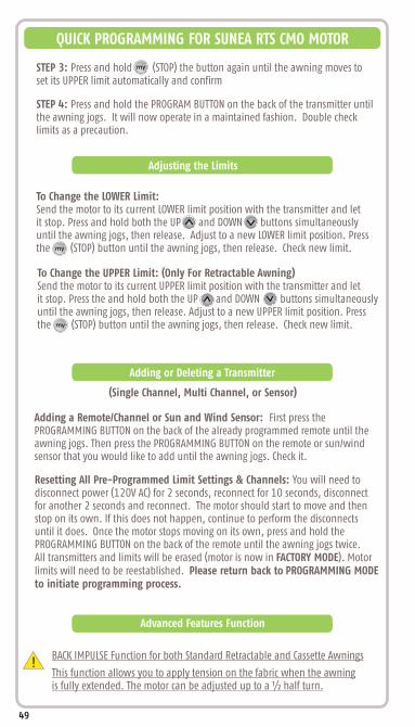
To Change the LOWER Limit:Send the motor to its current LOWER limit position with the transmitter and let it stop. Press and hold both the UP and DOWN buttons simultaneously until the awning jogs, then release. Adjust to a new LOWER limit position. Press the (STOP) button until the awning jogs, then release. Check new limit.my
To Change the UPPER Limit: (Only For Retractable Awning) Send the motor to its current UPPER limit position with the transmitter and let it stop. Press the and hold both the UP and DOWN buttons simultaneously until the awning jogs, then release. Adjust to a new UPPER limit position. Press the (STOP) button until the awning jogs, then release. Check new limit.my
STEP 3: set its UPPER limit automatically and confirm
Press and hold (STOP) the button again until the awning moves to
STEP 4: the awning jogs. It will now operate in a maintained fashion. Double check limits as a precaution.
Press and hold the PROGRAM BUTTON on the back of the transmitter until
my
Adjusting the Limits
Adding a Remote/Channel or Sun and Wind Sensor: First press the PROGRAMMING BUTTON on the back of the already programmed remote until the awning jogs. Then press the PROGRAMMING BUTTON on the remote or sun/windsensor that you would like to add until the awning jogs. Check it.
Resetting All Pre-Programmed Limit Settings & Channels: You will need to disconnect power (120V AC) for 2 seconds, reconnect for 10 seconds, disconnect for another 2 seconds and reconnect. The motor should start to move and then stop on its own. If this does not happen, continue to perform the disconnects until it does. Once the motor stops moving on its own, press and hold the PROGRAMMING BUTTON on the back of the remote until the awning jogs twice.All transmitters and limits will be erased (motor is now in FACTORY MODE). Motorlimits will need to be reestablished. Please return back to PROGRAMMING MODEto initiate programming process.
Adding or Deleting a Transmitter
(Single Channel, Multi Channel, or Sensor)
BACK IMPULSE Function for both Standard Retractable and Cassette Awnings
This function allows you to apply tension on the fabric when the awning is fully extended. The motor can be adjusted up to a ½ half turn.
Advanced Features Function
!
49
QUICK PROGRAMMING FOR SUNEA RTS CMO MOTOR

STEP 1: Set the awning to the lowest position.
To Activate this Function:STEP 2: Press and hold both the (STOP) and UP buttons simultaneously until the awning jogs. The motor is in PROGRAMMING MODE.
STEP 3: Adjust the fabric's tension using the UP or DOWN buttons.
STEP 4: Press the (STOP) button until the awning jogs. The fabric's tension has been programmed.
my
my
This function allows the fabric tension to be released after the cassette awning is closed.
To Activate this Function:STEP 1: Cut the power for 2 sec, then plug back in, unless you are using the awning in the first 4 cycles.
Set the awning to the UP or CLOSED limit position with the transmitter.
Press and hold both the (STOP) and DOWN buttons simultaneously until the awning jogs. If the Back release function was deactivated, it is activated. If the Back Release function was active, it is deactivated.
my
!
This function enables the closing force of the cassette awning to be increased or decreased to 3 levels (high/medium/low). The motor is factory set at the medium level.
To Activate this Function:STEP 2: Cut the power for 2 sec, then plug back in, unless you are using the awning in the first 4 cycles.
STEP 1: Bring the awning to the halfway position.
BACK RELEASE Function on Cassette Awnings Only
CLOSING FORCE Adjustment For on Cassette Awnings Only
!
STEP 3: Briefly press the (STOP) and UP buttons simultaneously, then immediately press and hold the (STOP) and UP buttons simultaneously until the motor jogs. The motor is only in PROGRAMMING MODE for approx. 10 seconds.
STEP 4: Adjust the closing force setting using the UP and DOWN buttons.- to increase the closing force, press the UP button until the motor jogs up and down.- to decrease the closing force, press the DOWN button until the motor jogs up and down (long jog for levels 3 and 1) (short jog for level 2).
my
my
STEP 5: Press and hold the (STOP) button until the awning jogs up and down. The new closing force has been programmed.
my
50
QUICK PROGRAMMING FOR SUNEA RTS CMO MOTOR
QUICK PROGRAMMING FOR GLYDEA RTS
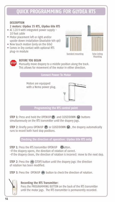
STEP 1: Press and hold the OPEN/UP and CLOSE/DOWN buttons simultaneously on the RTS transmitter until the drapery jogs.
STEP 1: Press the RTS transmitter OPEN/UP button.-If the drapery opens, the direction of rotation of correct.-If the drapery closes, the direction of rotation is incorrect: move to the next step.
STEP 2: Press the (STOP) button until the drapery jogs: the direction of rotation has been modified.
STEP 3: Press the OPEN/UP button to check the direction of rotation.
my
Recording the RTS Transmitter:Press the PROGRAMMING BUTTON on the back of the RTS transmitteruntil the motor jogs. The RTS transmitter is permanently recorded.
BEFORE YOU BEGINManually move drapery to a middle position along the track. This allows for movement of the motor in either direction.
Connect Power To Motor
Motors are equipped with a Nema power plug.
Programming the RTS control point
STEP 2: Briefly press OPEN/UP or CLOSE/DOWN , the drapery automatically runs to record both hard stop positions.
Checking the direction of operation: Glydea 60e RTS only
DESCRIPTION2 motors: Glydea 35 RTS, Glydea 60e RTSAC 120 V with integrated power supply - 10 foot cableMotor placement left or right and/or upside down installation (Available 4th qtr)New touch motion (only on the 60e)Comes in Dry contact with optional RTS plug-in module
Standard mounting False Ceiling Mounting
51

Recording “MY” favorite position:To set the (STOP) position, move the drapery to the desired intermediate position with the OPEN/UP or CLOSE/DOWN buttons then press the (STOP) button until the drapery jogs.
Delete the “MY” position:To delete the my (STOP) position, move to the current my (STOP) position, then press the (STOP) button until the drapery jogs.
my
my
my
OPEN/UP Limit Adjustment:STEP 1: Press the OPEN/UP button, to move the drapery to the limit to be re-adjusted.
STEP 2: Press and hold the OPEN/UP and CLOSE/DOWN buttons simultaneously until the drapery jogs.
STEP 3: Press and hold the OPEN/UP or CLOSE/DOWN buttons to move the drapery to the new desired position.
STEP 4: To confirm the new limit, press and hold the (STOP) button until the drapery jogs.
my
QUICK PROGRAMMING FOR GLYDEA RTS
my
52
Press briefly the OPEN/UP button to move the drapery to the OPEN/UP end limit
STEP 1: Press and hold the and CLOSE/DOWN buttons simultaneously until the drapery jogs. Press the CLOSE/DOWN button to re-adjust the back release position.
STEP 2: To confirm the new back release position, press and hold the (STOP) button until the drapery jogs. For accuracy, the positioning must be done in one movement. If the position is not satisfactory, repeat the enitreprocedures again.
my
my
STEP 3: To erase the back release position, set it on the hard stop limit.
It is required to set a back release position on thick draperies in order to allow proper manual operation.
!
Back Release Setting :
Setting Intermediate Preferred “My” Position:
Adjusting The Limits:
Glydea 60e RTS Only
Glydea 35 RTS Only
Glydea 60e RTS Only

STEP 1: Press OPEN/UP or CLOSE/DOWN to move the drapery away from the limit:
STEP 2: Press and hold the OPEN/UP and CLOSE/DOWN buttons simultan-eously until the drapery jogs.
STEP 3: Press the (STOP) button until the drapery jogs to reverse the rotation direction.
STEP 1: Press OPEN/UP or CLOSE/DOWN to move the drapery away from the limit:
STEP 2: Press and hold the OPEN/UP and CLOSE/DOWN buttons simultan-eously until the drapery jogs.
STEP 3: Press the (STOP) and CLOSE/DOWN buttons simultaneously until the drapery jogs to change the ergonomy.
my
STEP 1: Press OPEN/UP or CLOSE/DOWN to move the drapery away from the limit.
STEP 2: Press and hold the OPEN/UP and CLOSE/DOWN button simultan-eously until the draperies jogs.
QUICK PROGRAMMING FOR GLYDEA RTS
my
CLOSE/DOWN Limit Adjustment:STEP 1: Press the CLOSE/DOWN button to move the drapery to the limit to be re-adjusted.
STEP 2: Press and hold the OPEN/UP and CLOSE/DOWN buttons simultan-eously until the drapery jogs.
STEP 3: Press and hold the OPEN/UP or CLOSE/DOWN buttons to move the drapery to the new desired position.
STEP 4: To confirm the new limit, press and hold the (STOP) button until the drapery jogs.
my
Modifying the motor Rotation Direction
Dry Contact Mode Setting
Touch Motion Sensitivity:
Glydea 60e RTS only
53

QUICK PROGRAMMING FOR GLYDEA RTS
STEP 1: Press and hold the PROGRAMMING BUTTON of either the motors receiver or a transmitter already in memory until the drapery jogs. The motor is now in PROGRAMMING MODE.
STEP 2: Briefly press the PROGRAMMING BUTTON of the transmitter to addor delete, until the drapery jogs.
To delete all the transmitters programmed and retain limit setting, press and hold the receivers PROGRAM BUTTON until the drapery jogs twice.
Resetting completely the memory of the motor, press the receiver PROGRAM BUTTON until the drapery jogs 3 times. All the settings are erased.
STEP 1: Press and hold both the (STOP) and OPEN/UP buttons simultaneously until the drapery starts to open and close automatically without stopping.
STEP 2: Press OPEN/UP to increase speed, CLOSE/DOWN to decrease speed
STEP 3: Press the (STOP) button until the drapery jogs to confirm the setting.my
my
54
Adjustment Of Speed Setting:
Glydea 60e RTS only
Adding/Deleting RTS
Deleting Previous Setting
STEP 3: Press the OPEN/UP and CLOSE/DOWN buttons simultaneously until the drapery jogs to switch from no touch motion to low sensitivity; to high sensitivity; to high sensitivity and back to no touch motion.
STEP 4: Press the (STOP) button until the drapery jogs to confirm the setting.my

Adding a New Transmitter/Sensor to Memory
QUICK PROGRAMMING FOR OUTDOOR UNIVERSAL RECEIVER RTS
STEP 1: Set the Universal Receiver into PROGRAMMING MODE by pressing the PROGRAMMING BUTTON until the LED lights (about 2 seconds). The motor willjog.
Press and hold the PROGRAMMING BUTTON of the receiver for more than 7 seconds until the LED blinks and the motor jogs twice. This removes ALL memorized transmitters or sensors.
MOTOR
R
NEUTRALGROUND
UP
DOWN
MTR COM
NEUT
HOT
HOT
HOT
NEUT
GROUND
PROGRAMMING BUTTON
PROGRAMMING LED
Removing All Transmitters/Sensors from Memory
PROGRAMMING MODE
Step 1: Press the PROGRAMMING BUTTON, on the Outdoor Universal Receiver RTS for more than 2 seconds.
Step 2: The programming LED on the receiver will illuminate on and the motor will jog.
Step 3: Press the PROGRAMMING BUTTON on the new transmitter to record it to the receiver. The programming LED on the Receiver will blink, and the motor will jog indicating the transmitter is memorized.
Step 4: Operate the motor in the DOWN direction.
STEP 2: Press the PROGRAMMING BUTTON on the Telis transmitter or RTS sensorto be memorized. The programming LED will blink and the motor will jog indicating the device has been memorized.
SEQUENCE BUTTON
Add The First Transmitter To The Memory
Step 4: Operate the motor in the DOWN direction.
Step 5: The motorized treatment should move down or extend if this is incorrect, turn off power to the receiver and reverse the RED and BLACK wires. Failure to correct this error will cause damage to awning by extending it during windy conditions
55

QUICK PROGRAMMING FOR OUTDOOR LIGHTING RECEIVER RTS
PROGRAMMING MODE
Add the First Transmitter to the Memory
STEP 1: Press the PROGRAMMING BUTTON, on the Lighting Receiver for more than 2 seconds.STEP 2: The programming LED on the receiver will light, and the lamp will light for2 seconds.STEP 3: Press the PROGRAMMING BUTTON on the new transmitter to attach it to thereceiver. The programming LED on the Receiver will blink, and the lamp willlight indicating the transmitter is memorized.
Press and hold the PROGRAMMING BUTTON of the receiver for more than 7 seconds until the LED blinks and the light flashes twice. This removes ALL memorized transmitters or sensors.
Removing all transmitters from memory
Step 1: Press the PROGRAMMING BUTTON, on the Outdoor Lighting Receiver RTS for more than 2 seconds. Step 2: The programming LED on the receiver will illuminate, and the lamp will light for 2 seconds.Step 3: Press the PROGRAMMING BUTTON on the new transmitter to add it to the receiver. The programming LED on the Receiver will blink, and the lamp will light indicating the transmitter is memorized.
Add The First Transmitter To The Memory
Adding a New Transmitter to the Memory
STEP 1: Press the PROGRAMMING BUTTON, for more than 2 seconds, on a transmitterthat is already memorized by the Lighting Receiver.STEP 2: The programming LED on the receiver will light, and the lamp will light for 2 seconds.STEP 3: Press the PROGRAMMING BUTTON on the new transmitter to attach it to the receiver. The programming LED on the receiver will blink, and the lamp will light indicating the transmitter is memorized.
56
500 WATTS MAX.
NEUTRAL
GROUND
500W Max Lighting Output
NEUT
HOT
HOT
HOT
NEUT
GROUND
PROGRAMMING BUTTON
PROGRAMMING LED
SEQUENTIAL CONTROL BUTTON
LAMP

QUICK PROGRAMMING FOR RTS REPEATER
The Somfy RTS Repeater can be used in installations to extend the range of the ®standard Radio Technology Somfy signal. It will receive the signal from a Telis or
similar device and retransmit the signal to a RTS compatible motor or receiver.
Simply plug the receiver into any 120V AC outlet. It should be located at least halfway between the transmitting device (Telis) and receiving device (RTS Motor). The red LED will blink, indicating communication.
QUICK PROGRAMMING FOR UNIVERSAL RTS INTERFACE (URTSI)
Set the RTS receiver or motor into its PROGRAMMING MODE. Refer to the installation instructions of the relevant RTS receiver or motor for this procedure.
Using the rotary switch, select the channel to be programmed. Letter A throughF stand for channels 10 through 15, 0 for 16. Briefly press the PROGRAMMINGBUTTON (1 sec. max. The window treatment will jog to indicate the channel has been memorized.
Repeat the steps above for each channel or product to be memorized.
To test the control operation, simply press the UP, STOP or DOWN buttons on the front of the control. The window treatment should move appropriately. TheLED will flash red to indicate the radio signal has been transmitted.
PROGRAMMING MODE
For initial programming provide, power only to the motor or control being programmed.
!
57

Adding a Sunis Indoor Sensor
QUICK PROGRAMMING FOR SUNIS INDOOR WIREFREE SENSOR
STEP 1: Carefully remove rear cover to expose sensor control setting panel.
STEP 2: Slide the ON/OFF Selector Switch to the ON or position.
STEP 3: Set the motorized window covering into PROGRAMMING MODE (Refer to the installation instructions of the relevant RTS receiver or motor or this procedure).
STEP 4: Using a paper clip, pen or similar device, briefly press the PROGRAMMING BUTTON (for 1 second) located on the Sunis light sensor (See Figure 1 pg. 60). The motorized window covering will jog to confirm the addition of the new Sunis light sensor..
Repeat steps 1-3 when multiple motors are required to operate from the Sunis light sensor.
During initial programming, provide power only to motorizedwindow covering being programmed.
STEP 1: PROGRAMMING BUTTON addressed Sunis Light Sensor or Somfy transmitter (Telis, DecoFlex, etc.) (See Figure 1 pg. 60). The motorized window covering will jog to confirm PROGRAMMING MODE.
STEP 2: Using a paper clip, pen or similar device, briefly press the PROGRAMMING BUTTON (for 1 second) located on the Sunis Light Sensor to be deleted (See Figure 1 pg. 60). The motorized window covering will jog to confirm the deletion of the Sunis light sensor.
Using a paper clip, pen or similar device, press and hold the (for 3 seconds) on a previously
Deleting a Sunis Indoor Sensor from Memory
Sunis light sensor MUST be free from obstructions in order to correctly sense incoming light. Sill mount may not be suitable for some window installations (See Figure 2 pg. 62).
Outside ofWindow Glass
Outside ofWindow Glass
Front of Sunis towards outsideof window glass
SENSOR LOCATION WINDOW GLASS MOUNT WINDOW SILL MOUNT
PROGRAMMING MODE
!
!
!
Step 1 should not be performed with the Sunis intended for deletion.!
58

Sunis sensor should be mounted in or near window and exposed to incoming light.
QUICK PROGRAMMING FOR SUNIS INDOOR WIREFREE SENSOR
Setting the Light (Sun) Sensitivity (Threshold)
STEP 1: Refer to previous “Setting the Light (Sun) Sensitivity Threshold”instructions.
STEP 2: Sunis light sensor will send a DOWN COMMAND to the RTS receiver or motor after 5 minutes of sensing light within the set threshold.
STEP 3: Sunis RTS light sensor will send an UP COMMAND to the RTS receiver or motor after 30 Minutes of sensing light that HAS FALLEN BELOW THE SETTHRESHOLD.
GREEN LED: INDICATES SUN (Light) WITHIN THRESHOLD SETTINGRED LED: INDICATES SUN (LIGHT) BELOW THRESHOLD SETTING
OPERATING MODE
STEP 3: Momentarily press the MODE BUTTON. LED Indicator will illuminate for approximately 15 seconds.
LED Indicator light will remain illuminated for approximately 15 seconds. Should the LED Indicator light extinguish prior to establishing the light sensitivity (threshold) setting, simply press the MODE BUTTON momentarily to reactivate LED light.
STEP 4: Using a small screw driver or similar device, rotate the Sun Sensitivity Selector to the fully CLOCKWISE (+) position. LED Indicator light will illuminate red (See Figure 3 pg. 62).
STEP 5: Slowly rotate the Sun Sensitivity Selector COUNTER CLOCKWISE (-) until the LED Indicator illuminates to a green color. A green colored LED indicates the present light value (threshold). At this value (threshold) the Sunis sensor will provide the necessary DOWN COMMAND to the motorized window covering.
Default employs output response time delays.
STEP 1: Carefully remove rear cover of Sunis Light sensor exposing control setting panel.
!
STEP 2: Slide the ON/OFF Selector Switch to the ON or position.
!
59

The Sunis WireFree™ RTS Light Sensor uses a lithium battery (Type: CR2430). LED Indicator Light will illuminate orange when battery needs replacing.
STEP 1: Carefully remove rear cover of Sunis light sensor exposing the control setting panel (See Figure 4 pg. 62).
STEP 2: Firmly grip the molded indentations and rotate control setting panel counter clockwise to open position.
STEP 3: Carefully separate from sensor case to expose battery holder.
STEP 4: Replace battery with correct rated/type battery. Be certain of battery polarity (+) and (-) when installing new battery.
Replacing the Battery
Do not use any tools when replacing the battery as there is a risk of damaging the sensor circuitry.
ON/OFF Selector Switch
Control Setting Panel
ProgrammingButton
Rear Cover
FIGURE 1
LEDIndicator
QUICK PROGRAMMING FOR SUNIS INDOOR WIREFREE SENSOR
!
Programming Figures
60

Programming Figures
Window Glass Mount
Window Sill Mount
FIGURE 2
ON/OFF Selector Switch
Control Setting Panel
Mode Button
Sun Sensitivity Selector
LEDIndicator
FIGURE 3
(-)Requires
LessSunlight
(+)Requires
MoreSunlight
Sensor Case
Rear Cover
Control Setting Panel
FIGURE 4
QUICK PROGRAMMING FOR SUNIS INDOOR WIREFREE SENSOR
61

Adding a Thermo Sunis Indoor Sensor
QUICK PROGRAMMING FOR THERMO SUNIS INDOOR WIREFREE SENSOR
During initial programming, it is recommended that power is provided only to motorized window covering being programmed.
STEP 1: Carefully remove rear cover to expose sensor control setting panel.
Repeat steps 1-3 when multiple motorized window coverings are required to operate from the Thermo sunis sensor.
Deleting a Thermo Sunis Indoor Sensor from Memory
STEP 1: Using a paper clip, pen or similar device, press and hold the PROGRAMMING BUTTON (approximately 3 seconds) on a previously addressed Thermo Sunis or Somfy transmitter. (Telis, DecoFlex, etc.). The motorized window covering will jog to confirm PROGRAMMING MODE. STEP 2: Using a paper clip, pen or similar device, briefly press the PROGRAMMING BUTTON (for 1 second) located on the control setting panel of the Thermo Sunis to be deleted (See Figure 1 pg. 66). The motorized window covering will jog to confirm the deletion of the Thermo Sunis sensor.
Outside ofWindow Glass
Outside ofWindow Glass
Front of Sunis towards outsideof window glass
SENSOR LOCATION WINDOW GLASS MOUNT WINDOW SILL MOUNT
Thermo Sunis sensor MUST BE mounted indoors only and should be free from obstructions in order to correctly sense incoming light. Sill mounts may not be suitable for some window installations. (Sensor should be mounted in front of all interior window coverings (See Figure 2 pg. 67).
!
!
! Step 1 should not be performed with the Thermo Sunis intended for deletion.
!
STEP 2: Set the motorized window covering into PROGRAMMING MODE (Refer to the installation instructions of the relevant RTS receiver or motor for this procedure).
STEP 3: Slide the ON/OFF Selector Switch to the ON or position. Sun LED Indicator will illuminate for 5 seconds then extinguish.
STEP 4: Using a paper clip, pen or similar device, briefly press the PROGRAMMING BUTTON (for 1 second) located on the control setting panel of the Thermo Sunis. (See Figure 1 pg. 66). The motorized window covering will jog to confirm the addition of the Thermo Sunis sensor.
62

QUICK PROGRAMMING FOR THERMO SUNIS INDOOR WIREFREE SENSOR
Setting the (Temperature) Sensitivity (Threshold)
STEP 1: Carefully remove rear cover of the Thermo Sunis sensor Control Setting Panel (See Figure 4 pg. 67).
STEP 2: Slide the ON/OFF Selector Switch to the ON or position. Sun LED Indicator will illuminate for 5 seconds and then extinguish.
STEP 3: Momentarily press the MODE BUTTON and Sun LED Indicator Light will illuminate for approximately 15 seconds to indicate present threshold setting.
exposing
Thermo Sunis should be mounted in or near window and exposed to incoming sunlight.
Rotating the Sun Sensitivity Selector to a FULL COUNTER CLOCKWISE (-) position will simulate sun if no sun is present. It is not recommended to leave the selector (threshold setting) in this position.
!
LED Indicator light will remain illuminated for approximately 15 seconds. Should the LED Indicator light extinguish prior to establishing the light sensitivity (threshold) setting, simply press the MODE BUTTON momentarily to reactivate LED light.
!
STEP 4: Using a small screw driver or similar device, rotate the Sun Sensitivity Selector to the fully CLOCKWISE (+) position. LED Indicator will remain illuminated red color (See Figure 3 pg. 67).
STEP 5: Slowly rotate the Sun Sensitivity Selector COUNTER CLOCKWISE (-) until the LED Indicator illuminates to a green color. A green colored LED indicates the present light value (threshold). At this (threshold) the Thermo Sunis sensor will provide the necessary RTS command as selected with the Function Selector Switch.
GREEN LED: INDICATES SUNLIGHT WITHIN THRESHOLD SETTINGRED LED: INDICATE SUNLIGHT BELOW THRESHOLD SETTING
63

Step 1: Carefully remove rear cover of the Thermo Sunis sensor exposing Control Setting Panel (See Figure 4 pg. 67).
Step 2: Slide the ON/OFF Selector Switch to the ON or position. Sun LED Indicator will illuminate for 5 seconds and then extinguish. Step 3: Momentarily press the MODE BUTTON. Temperature LED Indicator will illuminate for approximately 15 seconds to indicate present threshold setting.
Setting the (temperature) Sensitivity (threshold)
Thermo Sunis should be mounted in or near window and exposed to incoming sunlight.
QUICK PROGRAMMING FOR THERMO SUNIS INDOOR WIREFREE SENSOR
LED Indicator light will remain illuminated for approximately 15seconds. Should the LED indicator light extinguish prior to establishing the temperature sensitivity (threshold) setting, simply press the MODE BUTTON momentarily to reactivate LED light.
Step 4: Using a small screw driver or similar device, rotate the Temperature Sensitivity Selector to the fully CLOCKWISE (+) position. Temperature LED Indicator will remain illuminated red color (See Figure 3 pg. 67).
Step 5: Slowly rotate the Temperature Sensitivity Selector COUNTER CLOCKWISE (-) until the LED Indicator illuminates to a green color. A green colored LED indicates the present temperature value (threshold). At this value (threshold) the Thermo Sunis sensor will provide the necessary RTS command as selected with the Function Selector Switch (for details reference Function Selector Switch below).
GREEN LED: INDICATES TEMPERATURE WITHIN THRESHOLD SETTINGRED LED: INDICATES TEMPERATURE BELOW THRESHOLD SETTING
!
64

*Command Mode 1
Go to DOWN Limitor Sensor Location
Go to UP Limit
Go to "my” Position
Go to UP Limit
Go to DOWN Limit
Go to "my” Position
my
my
Command Mode 2 Command Mode 3
1 2 3
After 5 Minutes
After 30 Minutes
(within threshold)
(below threshold)
= Sunlight/Temp sensor within the set “Threshold.” Thermo Sunis will provide an RTS command after approximately 5 minutes of sensing within the set threshold.
= Sunlight/Temp Sensor below the set “Threshold.” Thermo Sunis will provide an RTS command after approximately 30 minutes of sensing below the set threshold
*When selected for use with Exterior Rolling Shutter or Exterior Shade Applications, whereby the window covering is mounted externally to the window and Thermo Sunis sensor, the window covering will travel to location of sensor only. It is suggested that (Mode 1) is used to command no more than (1) window covering per sensor
STEP 1: Slide the Sun/Temp Selector Switch to the desired setting (See Figure 3 pg. 67).
= Activation of Window Covering via Sunlight only
= Activation of Window Covering via Temperature & Sunlight
STEP 2: Adjust Sunlight and Temperature Sensitivity (threshold) (Refer to Setting theSensor Sensitivity (threshold).
Slide the Function Selector Switch to provide the necessary RTS output commands to the window covering.
OR
Default employs output response time delays.
QUICK PROGRAMMING FOR THERMO SUNIS INDOOR WIREFREE SENSOR
OPERATING MODE
!
!
65

ON/OFFSelector Switch
Programming Button Control
Setting Panel
Rear Cover
Sun LEDIndicator
FIGURE 1
Programming Figures
*When selected for use with Interior Window Coverings, the Thermo Sunis sensor will provide RTS commands to preset window covering limits = (Go to DOWN Limit) = (Go to UP Limit).
Sun Activation (control via sunlight) is not possible unless temperature is within the preset threshold.
Momentarily press the Mode Button, sun & temperature LED Indicator lightwill illuminate (for approximately 15 seconds) to indicate preset sensor status.
GREEN LED: INDICATES SENSOR WITHIN THRESHOLD SETTINGRED LED: INDICATES SENSOR BELOW THRESHOLD SETTING
Replacing the battery
Activation of Window Covering Via:
QUICK PROGRAMMING FOR THERMO SUNIS INDOOR WIREFREE SENSOR
Temperature & Sunlight
Refer to Sunis Indoor pg.60. For Figure see pg.61
!
When (Sun & Temperature) control is selected, the Temperature threshold setting will TAKE PRIORITY over the Sun Threshold Setting.
!
The Thermo Sunis RTS Sensor is capable of providing control in accordance to sunlight and temperature conditions only. Once a command is sent, the Thermosunis will not send another command until there is a change in sunlight or temperature conditions.
!
66
Programming Figures
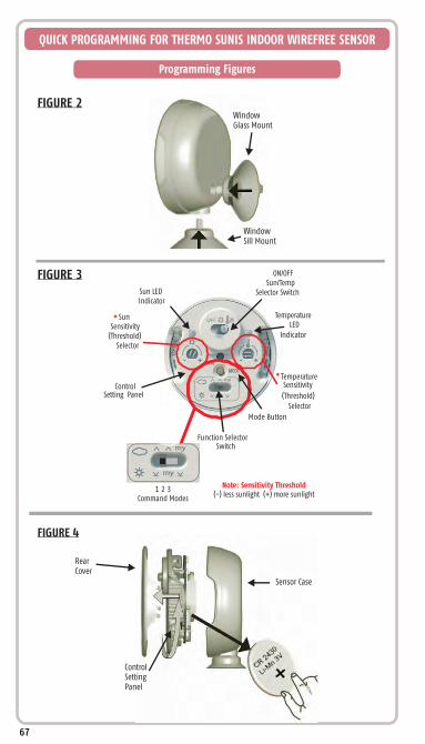
Sun LEDIndicator
SunSensitivity
(Threshold)Selector
ON/OFFSun/Temp
Selector Switch
Mode Button
Function SelectorSwitch
ControlSetting Panel
TemperatureSensitivity
(Threshold)
Selector
TemperatureLED
Indicator
1 2 3Command Modes
FIGURE 2
FIGURE 3
Sensor Case
Rear Cover
Control Setting Panel
FIGURE 4
Note: Sensitivity Threshold(-) less sunlight (+) more sunlight
*
*
Window Glass Mount
Window Sill Mount
QUICK PROGRAMMING FOR THERMO SUNIS INDOOR WIREFREE SENSOR
67

QUICK PROGRAMMING FOR EOLIS 3D WIREFREE WIND SENSOR™
ADDING BATTERIES
Awning
Awning Front Bar
Eolis 3D
Adding Batteries
STEP 1: Remove the sensor housing using a small screwdriver.
STEP 2: Install 2 AAA alkaline batteries (included). Make sure the red light blinks. If red light does not blink, check batteries for correct polarity.
Red Light
STEP 1: Press the PROGRAMMING BUTTON on the back of the remote until the awning jogs.
STEP 2: Press the PROGRAMMING BUTTON on the Eolis 3D Sensor until the awning jogs.
Pen
ProgrammingButton
ProgrammingButton
PROGRAMMING MODE
BEFORE YOU BEGINMake sure the "DOWN" button on the remote extends the awning.
Clear awning of any debris and make sure surface of awning is clean.
Apply tape and secure mounting plate to front bar of awning.
If this is incorrect please refer to relevant motor/receiver instructions to revearse the direction of operation for the awning.Failure to correct this error will causedamage to awning by extendingit during windy conditions.
68

QUICK PROGRAMMING FOR EOLIS 3D WIREFREE WIND SENSOR™
STEP 6: Test the sensor by pushing up and down on the awning front bar or arm until it begins to retract. You can use the remote to stop the awning after 5 seconds (first test mode).
STEP 7 : Bring the awning back out and test it again. You can use the remote to stop the awning after 5 seconds (second test mode).
Make adjustments to the sensitivity if needed and test it again.
STEP 5: Slide the housing back on the mounting plate.
STEP 4: Put the sensor electronics back in the housing.
STEP 3: Adjust the sensor dial to (4). (1= Most sensitive, 9= Least sensitive)
69

QUICK PROGRAMMING FOR OUTDOOR SUNIS WIREFREE SENSOR
STEP 1: Place Sunis in a charge for 10 minutes.
sunny area to
STEP 2: awning. Then press the PROGRAMMING BUTTON on the back of the original remote using a paper clip, pen or similar device until the awning jogs.
Completely retract the
STEP 3: PROGRAMMING BUTTON on the back of the Sunis until theawning jogs.
Press the
STEP 4: on theSunis completely counter clockwise and allow direct sunlight to shine on the front for 2 minutes.
Turn intensity knob
The awning should extend. Make adjustments to the sensitivity and in the path of direct sunlight.
mount it
70
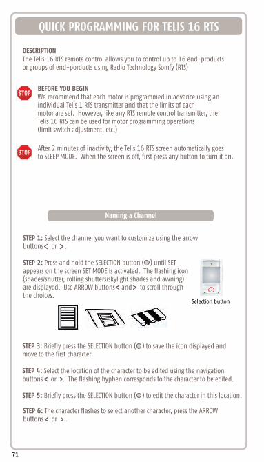
QUICK PROGRAMMING FOR TELIS 16 RTS
DESCRIPTIONThe Telis 16 RTS remote control allows you to control up to 16 end-products or groups of end-porducts using Radio Technology Somfy (RTS)
BEFORE YOU BEGINWe recommend that each motor is programmed in advance using an individual Telis 1 RTS transmitter and that the limits of each motor are set. However, like any RTS remote control transmitter, the Telis 16 RTS can be used for motor programming operations (limit switch adjustment, etc.)
After 2 minutes of inactivity, the Telis 16 RTS screen automatically goesto SLEEP MODE. When the screen is off, first press any button to turn it on.
STEP 1: Select the channel you want to customize using the arrow buttons or .
STEP 2: Press and hold the SELECTION button ( ) until SET appears on the screen SET MODE is activated. The flashing icon (shades/shutter, rolling shutters/skylight shades and awning) are displayed. Use ARROW buttons and to scroll through the choices.
Naming a Channel
71
STEP 6: The character flashes to select another character, press the ARROWbuttons or .
STEP 3: Briefly press the SELECTION button ( ) to save the icon displayed and move to the first character.
STEP 4: Select the location of the character to be edited using the navigation buttons or . The flashing hyphen corresponds to the character to be edited.
STEP 5: Briefly press the SELECTION button ( ) to edit the character in this location.
Selection button

The characters (7 letters +1 number) can be alphabetic (A to Z) or numeric (0 to 9)
!
Naming Other Channels: Repeat steps 1 to 9 for each channel you want to customize.
!
QUICK PROGRAMMING FOR TELIS 16 RTS
Adding or Deleting Transmitter/Channel
The procedure for assigning window coverings to the channels of theTelis 16 RTS and deleting them is identical.
!
STEP 1: Press and hold the PROGRAMMING BUTTON on the individual RTStransmitter that has already been programmed until the window coverings jogs: PROGRAMMING MODE is activated for 2 minutes.
STEP 2: Use the ARROW buttons or to select the channel on the Telis 16RTS to be programmed.
STEP 3: Briefly press the PROGRAMMING BUTTON on the Telis 16 RTS. The window coverings jogs back and forth and it is assigned to or deleted from the chosen channel on the Telis 16 RTS.
In order to assign or delete the window covering from other channels, repeat steps 1 to 3, selecting another channel.
!
72
STEP 7: Briefly press the SELECTION button to save the character displayed andmove to the next character.
STEP 8: Repeat steps 4 to 7 for each of the characters in the channels name.
STEP 9: Press and hold the SELECTION button until SET is no longer displayed onthe screen SET MODE is deactivated, and the Telis 16 Chronis RTS returns toMANUAL MODE.

QUICK PROGRAMMING FOR TELIS 6 CHRONIS RTS
DESCRIPTIONThe Telis 6 Chronis RTS remote control transmitter allows you to control up to6 end-products or groups of window coverings using Radio Technology Somfy(RTS). The Telis 6 Chronis can be used in 2 ways: in either MANUAL or AUTOMATIC MODE.
MANUAL MODE allows you to control window coverings in the house in groups or individually, depending on their assignments to the 6 groups on the remotecontrol transmitter, called “channels”. The channels, numbered 1 to 6, canbe customized, by assigning names to each channel.
AUTOMATIC MODE allows you to control the window covering assigned to the channels on the remote control transmitter automatically, after having created the weekly and daily programs, called “automatic commands”. Up to 6 automatic commands can be programmed for each day of the week.
BEFORE YOU BEGINWe recommend that each motor is programmed in advance using an individual Telis 1 RTS transmitter and that the limits of each motor are set. However, like any RTS remote control transmitter, the Telis 6 Chronis RTS can be used for motor programming operations (limit switch adjustment, etc.)
After 2 minutes of inactivity, the Telis 6 Chronis RTS screen automaticallygoes to SLEEP MODE. When the screen is off, first press any button to turn it on. When editing the settings, you can switch between MANUAL MODE or AUTOMATIC MODE at any time by pressing briefly the SELECTION button( ). Only confirmed parameters are saved.
73
Selection button

QUICK PROGRAMMING FOR TELIS 6 CHRONIS RTS
At each stage, the parameter to be set flashes.
STEP 1: Press the ARROW buttons or to change the parameter (pressing andholding the button scrolls the characters faster).
STEP 2: To save the parameter and move to the next parameter, briefly press the SELECTION button ( ),
STEP 3: REMOTE CONTROL SETTING MODE can be deactivated at any time by pressing and holding the SELECTION button ( ). Only confirmed parameters are saved.
Setting the General Parameters
When the batteries are first installed, REMOTE CONTROL SETTINGS MODEis activated directly: SET and YEAR appear on the screen, with the year flashing (this is the first parameter to be set).
If there is no power supply for an extended period of time (batteries discharged or removed), the general parameters of the remote control transmitter will have to be reset. However, automatic commands remain stored in memory.
!
74

QUICK PROGRAMMING FOR TELIS 6 CHRONIS RTS
The twilight times must be set between 6 am and 11 pm.
!
STEP 11: Whether or not
there are sun sensors on
site select SUN (one or
more sun sensors) or NO
SUN (no sun sensors).
STEP 12: Briefly press the
SELECTION button ( ) to
confirm the last parameter.
REMOTE CONTROL SETTINGS
MODE is deactivated, and
the Telis 6 Chronis RTS
returns to AUTOMATIC MODE.
REMOTE CONTROL SETTINGS MODE can be deactivated at any time by pressing and holding the SELECTION button. Only confirmed parameters are saved.
!
Set the Following Parameters:
STEP 1: YEAR (current year)
STEP 2: MONTH (number of the current month)
STEP 3: DAY (number of the current day)
STEP 4/5: TIME (current time in hours and minutes)
STEP 6: AREA (”US/EU” To automatically adjust for Daylight savings)
STEP 7/8: JUNE (”Dusk/Twilight time” during midsummer, in
hours and minutes)
STEP 9/10: DEC (”Dusk/Twilight time” during midwinter, in December,
in hours and minutes)
75

QUICK PROGRAMMING FOR TELIS 6 CHRONIS RTS
The 5 characters can be alphabetic (A to Z) or numeric (0 to 9)!
Naming Other Channels: Repeat steps 1 to 9 for each channel you want to customize.
!
Naming a Channel
STEP 1: The Telis 6 Chronis RTS must be in MANUAL MODE (if its in AUTOMATIC MODE, briefly press the SELECTION button ( ) to switch to MANUAL MODE).
STEP 2: Select the channel you want to customize using theARROW buttons or .
STEP 3: Press and hold the SELECTION button ( ) until SET appears on the screenSET MODE is activated. The flashing hyphen corresponds to the character tobe edited.
STEP 4: Select the location of the character to be edited using the navigation buttons or . The flashing hyphen corresponds to the character to be edited.
STEP 5: Briefly press the SELECTION button ( ) to edit the character in this location.
STEP 6: The character flashes to select another character, press the ARROWbuttons or .
STEP 7: Briefly press the SELECTION button ( ) to save the character displayed and move to the next character.
STEP 8: Repeat steps 4 to 7 for each of the characters in the channels name.
STEP 9: Press and hold the SELECTION ( ) button until SET is no longer displayed on the screen SET MODE is deactivated, and the Telis 6 Chronis RTS returns toMANUAL MODE.
Channels Can Only be Named in MANUAL MODE
76

QUICK PROGRAMMING FOR TELIS 6 CHRONIS RTS
Adding or Deleting Transmitter/Channel
The procedure for assigning window coverings to the channels of the Telis 6 Chronis RTS and deleting them is identical. It can only be done in MANUAL MODE.
!
STEP 1: Make sure that the Telis 6 Chronis RTS is in MANUAL MODE (if it is inAUTOMATIC MODE, briefly press the SELECTION button ( ) to switch to MANUAL MODE).
STEP 2: Press and hold the PROGRAMMING BUTTON on the individual RTStransmitter already in memory until the window covering jogs.
STEP 3: Use the ARROW buttons or to select the channel on the Telis 6Chronis RTS to be programmed.
STEP 4: Briefly press the PROGRAMMING BUTTON on the Telis 6 Chronis RTS:the window covering jogs and it is assigned to or deleted from the chosen channel on the Telis 6 Chronis RTS.
In order to assign or delete the window covering from other channels, repeat steps 1 to 4, selecting another channel. To assign or delete other window coverings, repeat steps 1 to 4.
!
77
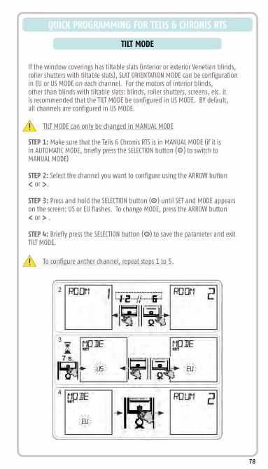
TILT MODE
QUICK PROGRAMMING FOR TELIS 6 CHRONIS RTS
If the window coverings has tiltable slats (interior or exterior Venetian blinds,roller shutters with tiltable slats), SLAT ORIENTATION MODE can be configurationin EU or US MODE on each channel. For the motors of interior blinds,other than blinds with tiltable slats: blinds, roller shutters, screens, etc. itis recommended that the TILT MODE be configured in US MODE. BY default,all channels are configured in US MODE.
! TILT MODE can only be changed in MANUAL MODE
STEP 1: Make sure that the Telis 6 Chronis RTS is in MANUAL MODE (if it isin AUTOMATIC MODE, briefly press the SELECTION button ( ) to switch toMANUAL MODE)
STEP 2: Select the channel you want to configure using the ARROW button or .
STEP 3: Press and hold the SELECTION button ( ) until SET and MODE appearson the screen: US or EU flashes. To change MODE, press the ARROW button or .
STEP 4: Briefly press the SELECTION button ( ) to save the parameter and exitTILT MODE.
! To configure anther channel, repeat steps 1 to 5.
78

QUICK PROGRAMMING FOR TELIS 6 CHRONIS RTS
Programming the days of the week
The Telis 6 Chronis can automatically send orders to one or more groups of window coverings when it is in AUTOMATIC MODE, after creating a program. Up to 6 automatic commands any combination of the 6 can be programmed for each day of the week.
Each of these Automatic Orders can be:1. Set for a specific set time or a twilight/dusk
2. Applied to 1 to 6 channels (all window coverings on the same channel are controlled at the same time) , , , (on), (off), chosen commands.
The days of the week can only be programmed in AUTOMATIC MODE.AUTOMATIC COMMAND PROGRAMMING MODE can be deactivated at any time by pressing and holding the SELECTION button ( ). Only confirmed parameters are saved.
!
Selecting the Day to Be Programmed
STEP 1: Make sure that the Telis 6 Chronis RTS is in AUTOMATIC MODE (if it is in MANUAL MODE, briefly press the SELECTION button ( ) to switch toAUTOMATIC MODE).
STEP 2: Press and hold the SELECTION button ( ) until SET appears on the screen:AUTOMATIC COMMAND PROGRAMMING MODE is activated, and the day previously displayed flashes.
STEP 3: Select the day you want to program using the ARROW buttons or .
STEP 4: Briefly press the SELECTION button ( ) to program the day that is flashing: EDIT appears and flashes
my
79

QUICK PROGRAMMING FOR TELIS 6 CHRONIS RTS
STEP 5: When EDIT flashes, briefly press the SELECTION button ( ) an AUTOMATIC ORDER flashes.
Editing an Automatic Order
STEP 6: To create a new AUTOMATIC ORDER: select the blank order using the ARROW buttons or and go to step 7. (If 6 automatic orders have already been created, only one of these orders can be modified).
Creating or Modifying an AUTOMATIC ORDER
Selecting the Time
STEP 7: Briefly press the SELECTION button ( ) to confirm the selection: the time flashes.STEP 8: Use the ARROW buttons or , to select the twilight option or at a set time and briefly press the SELECTION button ( ) to confirm the selection. To edit a twilight time, go to SELECTING THE CHANNELS. To edit a set time, go to next step.STEP 9: The hour flashes: to change the hour, press the ARROW buttons or .STEP 10: Briefly press the SELECTION button ( ) to confirm the hour and then set the minutes.STEP 11: The minutes flash: to change the minutes, press the arrow buttons or .STEP 12: Briefly press the SELECTION button ( ) to confirm the time and then set the channels.
Selecting the Channels
STEP 13: Select the channel to be activated using the ARROW buttons or then briefly press the SELECTION button ( ) to activate (symbol ) or deactivate (symbol ) the channel (to respond to timed commands).STEP 14: Press the ARROW buttons or to select another channel and repeat “STEP 13” to activate or deactivate each channel.STEP 15: Once the channels have been selected, press the ARROW buttons or until all 6 channels flash simultaneously. STEP 16: Briefly press the SELECTION button ( ) to confirm the channel selection and then set the command.
-To modify an automatic command: select the “automatic command” to be modified using the ARROW buttons or and go to SELECTING THE TIME.
Selecting the Command to be Sent
STEP 17: An order flashes: to select an command from , , , (on), (off) press the ARROW buttons or .
The (on) and (off) orders are not displayed when programmingthe days of the week if NO SUN (no sun sensors) was selected when the general parameters of the timer were set.
my
!
80

QUICK PROGRAMMING FOR TELIS 6 CHRONIS RTS
STEP 18: Briefly press the SELECTION button ( ) to confirm the order selected: the day concerned flashes.
STEP 19: Press and hold the SELECTION button ( ) to exit SET MODE and return to AUTOMATIC MODE.
81
-To modify another AUTOMATIC COMMAND, repeat the procedure starting at STEP 1.-To program ANOTHER DAY, repeat the procedure starting at STEP 1-To copy the program for one day and assign it to another day, see the COPYING THE PROGRAM FROM ONE DAY TO ANOTHER-To delete an automatic order, see the DELETING THE AUTOMATIC COMMAND section.

QUICK PROGRAMMING FOR TELIS 6 CHRONIS RTS
Copying the Program from One Day to Another
When the program for one particular day is identical to that of another day of the week, the copy/paste function can be used to copy the entire program that has already been configured for one day and paste it to another day.
STEP 1: Make sure that the Telis 6 Chronis RTS is in AUTOMATIC MODE (if is in MANUAL MODE, briefly press the SELECTION button ( ) to switch to AUTOMATIC MODE.
STEP 2: Press and hold the SELECTION button ( ) until "SET" appears on the screen: AUTOMATIC COMMAND PROGRAMMING MODE is activated, and the day previously displayed flashes.
STEP 3: Select the day you want to copy using the ARROW buttons or .
STEP 4: When the day to be copied flashes briefly, press the 2 ARROW buttons and simultaneously: COPY appears.
STEP 5: Select the day to which the program is to be copied using the ARROW buttons or .
STEP 6: Press both arrow buttons and simultaneously: “PASTE” appears, the program that was copied is pasted onto this other day.
STEP 7: Press and hold the SELECTION button ( ) to exit SET MODE and return to AUTOMATIC MODE.
82

QUICK PROGRAMMING FOR TELIS 6 CHRONIS RTS
Deleting an Automatic Command
STEP 1: Make sure that the Telis 6 Chronis RTS is in AUTOMATIC MODE (if it is in MANUAL MODE, briefly press the SELECTION button ( ) to switch to AUTOMATIC MODE).
STEP 2: Press and hold the SELECTION button until "SET" appears on the screen: AUTOMATIC COMMAND PROGRAMMING MODE is activated, and the day previously displayed flashes.
STEP 3: Select the day you want to modify using the ARROW buttons or .
STEP 4: Briefly press the SELECTION button ( ) to modify the program of the day that is flashing: "EDIT" appears and flashes.
STEP 5: Press one of the ARROW buttons or to change menu: "DELETE" (delete) flashes.
STEP 6: Briefly press the SELECTION button ( ) to confirm: an automatic order flashes.
STEP 7: Using the ARROW buttons or select the automatic command to be deleted and briefly press the SELECTION button ( ) to delete the automatic command that is flashing: the automatic command is deleted.
STEP 8: Press and hold the SELECTION button ( ) to exit "SET" mode and return to AUTOMATIC MODE.
83

OPERATION IN USER MODE
QUICK PROGRAMMING FOR TELIS 6 CHRONIS RTS
To switch from MANUAL to AUTOMATIC MODE, or AUTOMATIC to MANUAL MODE, briefly press the SELECTION button ( ).!
MANUAL MODE
MANUAL MODE on the Telis 6 Chronis RTS is used to:-Send an occasional order to the window coverings assigned to the 6 different channels-Deactivate automatic command programming. For example, Channel 1 “ROOM” is used to open the shades of the parents bedroom, Channel 2 “LIVIN” is used to move the shades in the livingroom to the ideal position to avoid glare on the computer and TV screens, and Channel 3 “Patio” is used to lower the awning to go and sit outside, etc.
When MANUAL MODE is selected, the sun function is automatically deactivated.The function will be reactivated at the next programmed (Sun on) automatic command.
Controlling the Channels Manually
STEP 1: Select the channel of the Telis 6 Chronis RTS to be used with the ARROW buttons or : each channel is identified by a number and the selected name (see "Naming of channels" section).
STEP 2: Briefly press the , , or a button corresponding to the desired command.
STEP 3: When the intermediate position has been programmed and the window covering is stopped, briefly press (STOP): the window covering or the group of window coverings is activated and goes to the “MY” (STOP) favourite position.
84
my
my

QUICK PROGRAMMING FOR TELIS 6 CHRONIS RTS
AUTOMATIC MODE
AUTOMATIC MODE on the Telis 6 Chronis RTS is used to:
-Automatically control the window coverings assigned to the 6 different channels, using automatic commands programmed according to the days of the week.
-Program the activation or deactivation of the SUN function, according to the channels.
-Programming the automatic orders for each day of the week (see Programming the days of the week section).
-In AUTOMATIC MODE, the current day and the next automatic command scheduled for that day are displayed.
-To view all automatic orders that have been programmed, scroll from one to the other using the ARROW button or . -To stop an automatic order that is in progress, return to MANUAL MODE by briefly pressing the SELECTION button ( ), select the channel corresponding to the window coverings concerned and press the (STOP) button.
85
my

QUICK PROGRAMMING FOR TELIS 6 CHRONIS RTS
VACATION MODE
In AUTOMATIC MODE, the “VACATION MODE” function randomly changes the timesat which the programmed automatic commands are sent, within a range of 0 to 30minutes. This function is specially recommended to simulate your presence whenyou are away from home for an extended period of time.
To Activate the Function:STEP 1: Make sure the Telis 6 Chronis RTS is in AUTOMATIC MODE (if it is in MANUAL MODE, briefly press the SELECTION button ( ) to switch to AUTOMATIC MODE).
STEP 2: Press both ARROW buttons and simultaneously: the ( ) symbolappears on the screen: the VACATION MODE function is activated.
To Deactivate the Function:Press both ARROW buttons and simultaneously: the ( ) symboldisappears from the screen: the VACATION MODE function is deactivated.
OR switch to MANUAL MODE
86
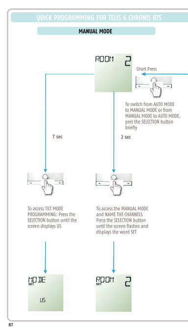
2 sec7 sec
MANUAL MODE
QUICK PROGRAMMING FOR TELIS 6 CHRONIS RTS
To switch from AUTO MODEto MANUAL MODE or fromMANUAL MODE to AUTO MODE,pres the SELECTION buttonbriefly
To access TILT MODEPROGRAMMING: Press theSELECTION button until thescreen displays US
To access the MANUAL MODEand NAME THE CHANNELSPress the SELECTION buttonuntil the screen flashes anddisplays the word SET
87
Short Press

AUTOMATIC MODE
To switch from AUTO MODEto MANUAL MODE or fromMANUAL MODE to AUTO MODE,pres the SELECTION buttonbriefly
2 sec 7 sec
Short Press
To access the AUTO MODE and SET TIMES RANGES Press the SELECTION button until the screen flashes and displays the word SET
To access the GENERAL MODE and SET THE GENERAL PARAMETERS Press the SELECTION button until the screen displays YEAR.
88

TROUBLESHOOTING RTS MOTORS
BEFORE YOU CALL FOR SERVICE:
Verify the motor is powered
Verify the motor is installed correctly inside the tube
(Crown & Drive correctly installed)
Verify the motor limits are set correctly
Allow time for motor to cool off after continuous operation
(motors are equipped with a thermal shut off for safety)
Verify the motor is not over loaded
Verify all sensors on location are within RTS range and are
working properly
Check the transmitter batteries
(LED should flash with a button press)
Verify the correct Somfy transmitter is being used and that
it is properly programmed into the motors memory
Do not cut power cable shorter than 12 inches
(the power cable acts as an antenna)
The mounting distance between 2 motor heads should not
be less than 19 inches between RTS motor heads, to avoid possible
radio interference.
Verify there is no outside radio interference on location
In PROGRAMMING MODE and LIMIT ADJUSTMENT MODE the radio
reception of the motor is reduced. It is necessary to move the
transmitter closer to the motor head during this time.
NOTES
89
Please visit the technical support section of or call Somfy Customer Service at 877-22-SOMFY
www.somfysystems.com

www.somfysystems.com
© C
opyr
ight
Som
fy S
yste
ms,
Inc.
4/2
011
L-
0156
Somfy Systems, Inc.North America Headquarters121 Herrod BlvdDayton, NJ 08810(P) 800 43SOMFY(P) 609 395 1300(F) 609 395 1776
Florida6100 Broken Sound PkwyNorthwest Suite 14Boca Raton, FL 33487(P) 877 227 6639(P) 561 995 8376(F) 561 995 7502
California15291 Barranca PkwyIrvine, CA 92618(P) 877 727 6639(F) 949 727 3775
Somfy UlcSomfy Canada6315 Shawson Drive Unit 1Mississauga, Ontario L5T1J2(P) 800 667 6639(P) 905 564 6446(F) 905 564 2679