rtv900 (for europe)(e)-9y011-15630 - kubota the oil into the service port. ... is composed of the...
TRANSCRIPT

RTV900
WORKSHOP MANUALUTILITY VEHICLE
KiSC issued 04, 2006 A
9 NEW TRANSMISSION
The machine RTV900 serial numbers of the new transmission for Europe were changed into those starting with “20001” for homologation versions, and into those starting with “60001” for non-homologation version.
KiSC issued 04, 2006 A
TO THE READER
The WSM (No. 97897-15320) for RTV900 has already been issued.
The New Transmission of RTV900. Additional information has been prepared as theWSM for 2006 Model based on the WSM for RTV900.
Please use it by attaching to the end of the WSM (No. 97897-15320) of RTV900.
April 2006© KUBOTA Corporation 2006
KiSC issued 04, 2006 A

CONTENTS
TRAVELING SPEEDS ............................................................................................. 1
G. GENERAL ...................................................................................................... G-1[1] LUBRICANTS, FUEL AND COOLANT.................................................. G-1[2] MAINTENANCE CHECK LIST................................................................ G-3[3] CHECK AND MAINTENANCE................................................................ G-3
9. NEW TRANSMISSION ................................................................................ 9-M1[1] MECHANISM........................................................................................... 9-M1[2] SERVICING ..............................................................................................9-S1
KiSC issued 04, 2006 A

1
RTV900, WSM TRAVELING SPEEDS
TRAVELING SPEEDS
The company reserves the right to change the specifications without notice.W1035065
[EC Homologated Version]
The company reserves the right to change the specifications without notice.W1028608
Model General Purpose Worksite Recreational
Tire size (Rear) 25 × 10 – 12 Knobby 25 × 10 – 12 HDWS 25 × 11 – 12 ATV
Range gear shift lever km/h (mph)
Low 16 (10)
Medium 29 (18)
High 40 (25)
Reverse 20 (12)
Model Worksite Recreational
Tire size (Rear) 25 × 10 – 12 HDWS 25 × 11 – 12 ATV
Range gear shift lever km/h (mph)
Low 16 (10)
Medium 29 (18)
High 40 (25)
Reverse 20 (12)
KiSC issued 04, 2006 A

G-1
RTV900, WSM G GENERAL
G. GENERAL[1] LUBRICANTS, FUEL AND COOLANT
*KUBOTA original transmission hydraulic fluid.
No. Place Capacity Lubricants, fuel and coolant
1 Fuel tank28.0 L
7.4 U.S.gals 6.2 Imp.gals
No. 2-D diesel fuel No. 1-D diesel fuel if temperature is below −10 °C (14 °F)
2Cooling system with recovery tank
4.0 L 4.2 U.S.qts 3.5 Imp.qts
Fresh clean water with anti-freeze
3Engine crankcase with oil filter
(Oil filter exchanged) 3.1 L
3.3 U.S.qts 2.7 Imp.qts
(Oil filter non-exchanged) 2.7 L
2.9 U.S.qts 2.4 Imp.qts
Engine oil : API Service CC, CD or CF Below 0 °C (32 °F) : SAE10W, 10W-30 or 10W-40 0 to 25 °C (32 to 77 °F): SAE20, 10W-30 or 10W-40 Above 25 °C (77 °F): SAE30, 10W-30 or 10W-40
4 Transmission case10.0 L
2.6 U.S.gals 2.2 Imp.gals
KUBOTA UDT or SUPER UDT fluid*
5 Front axle case0.6 L
0.63 U.S.qts 0.52 Imp.qts
KUBOTA UDT or SUPER UDT fluid*
6 Knuckle caseRef. 0.15 L
Ref. 0.16 U.S.qts Ref. 0.13 Imp.qts
KUBOTA UDT or SUPER UDT fluid*
7Brake fluid (reservoir and lines)
0.4 L 0.42 U.S.qts 0.35 Imp.qts
KUBOTA DOT3 GENUINE BRAKE FLUID
8
Hydraulic lift oil (Hydraulic dumping system model)
8.0 L 2.1 U.S.gals 1.8 Imp.gals
KUBOTA UDT or SUPER UDT fluid*Hydraulic lift oil (Hydraulic PTO model)
7.0 L 1.8 U.S.gals 1.5 Imp.gals
9 Power steering oil5.9 L
1.6 U.S.gals 1.3 Imp.gals
KiSC issued 04, 2006 A

G-2
RTV900, WSM G GENERAL
NOTE■• Engine Oil :
Oil used in the engine should have an American Petroleum Institute (API) service classification and ProperSAE Engine Oil according to the ambient temperatures as shown above.
• Transmission oil : The oil used to lubricate the transmission is also used as hydraulic fluid. To insure proper operation ofthe hydraulic system and complete lubrication of the transmission, it is important that a multi-gradetransmission fluid be used in this system. We recommend the use of KUBOTA SUPER UDT fluid foroptimum protection and performance. Do not mix different brands or grades.
• Brake fluid : Always use KUBOTA DOT3 GENUINE BRAKE FLUID from a sealed container. If it is not available, youshould use only DOT3 fluid as a temporary replacement from a sealed container. However, the use of any non-KUBOTA brake fluid can cause corrosion and decrease the lift of the system.Have the brake system flushed and refilled with KUBOTA DOT3 GENUINE BRAKE FLUID as soon aspossible.
• Indicated capacity of water and oil are manufacturer's estimate.• Lubricating Oil
With the emission control now in effect, the CF-4 and CG-4 lubricating oils have been developed for useof a low-sulfur fuel on-road vehicle engines. When an off-road vehicle engine runs on a high-sulfur fuel,it is advisable to employ the CF, CD or CE lubricating oil with a high total base number. If the CF-4 or CG-4 lubricating oil is used with a high-sulfur fuel, change the lubricating oil at shorter intervals.
• Lubricating oil recommended when a low-sulfur or high-sulfur fuel is employed.
❍ : Recommendable X : Not recommendableW1035555
Greasing
No. Place No. of greasing point Capacity Type of grease
10 VHT link 2 Until grease overflow
Multipurpose type greaseNLGI-2 or NLGI-1(GC-LB)
11 Battery terminal 2
Moderate amount
12Cargo lift cylinder pivot
2
13 Cargo bed pivot 2
14Parking brake linkage
4
15Range gear shift lever pivot
1
16 4WD lever pivot 1
17VHT pressure release
1
18 Accelerator wire – Engine oil
Fuel
Lubricatingoil class
Low sulfur(0.5 % ≥)
High sulfur Remarks
CF ❍ ❍ TBN ≥ 10
CF-4 ❍ X
CG-4 ❍ X
KiSC issued 04, 2006 A

G-3
RTV900, WSM G GENERAL
[2] MAINTENANCE CHECK LIST
[3] CHECK AND MAINTENANCE(1) Check Point of Every 50 Hours
Greasing1. Apply a small amount of multi-purpose grease to the following
points every 50 hours. If you operated the machine in extremelywet and muddy conditions, lubricate grease fittings more often.
W1043114
No.
Period
Item
Indication on hour meterImpor-
tant
Refer-ence page50 100 150 200 250 300 350 400 450 500 550
2 Greasing Apply ✩ ✩ ✩ ✩ ✩ ✩ ✩ ✩ ✩ ✩ ✩ G-3
No.
Period
Item
Indication on hour meter After purchaseImpor-
tant
Refer-ence page600 650 700 750 800 1500 3000 1 year 2
years4
years
2 Greasing Apply ✩ ✩ ✩ ✩ ✩ G-3
(1) Grease Fitting(VHT Pressure Release)
KiSC issued 04, 2006 A

CONTENTS
MECHANISM
1. STRUCTURE ................................................................................................. 9-M12. OIL FLOW ..................................................................................................... 9-M33. BYPASS VALVE ........................................................................................... 9-M44. CONTROL LINKAGE FOR BYPASS VALVE........................................... 9-M12
KiSC issued 04, 2006 A
9-M1
RTV900, WSM NEW TRANSMISSION
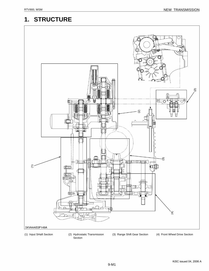
1. STRUCTURE
(1) Input SHaft Section (2) Hydrostatic Transmission Section
(3) Range Shift Gear Section (4) Front Wheel Drive Section
KiSC issued 04, 2006 A

9-M2
RTV900, WSM NEW TRANSMISSION
(1) Input Shaft (Pump Shaft)(2) Feedback Lever(3) Regulator Shaft(4) Output Shaft (Motor Shaft)(5) Charge Pump(6) Variable Swashplate (Pump)(7) HST Oil Filter Cartridge
(8) Piston(9) Cylinder Block (Pump)
(10) Port Block Cover(11) Suction Oil Filter Cartridge(12) Charge Relief Valve(13) Control Piston(14) Assist Motor Cover
(15) Variable Swashplate (Assist Motor)
(16) Piston(17) Cylinder Block (Assist Motor)(18) Bypass Spool(19) Cylinder Block (Motor)(20) Piston
(21) Servo Piston(22) Guide(23) Cradle Bearing(24) Regulator Spool(25) Regulator Valve Assembly(26) Check and High Pressure
Relief Valve
KiSC issued 04, 2006 A

9-M3
RTV900, WSM NEW TRANSMISSION
2. OIL FLOW
A charge pump (10) is used to feed oil to the hydrostatic transmission (HST). The oil coming from the charge pump(10) flows through the oil cooler (6) and oil filter cartridge (5) into the HST main circuit and regulator valve (4). At thistime, the servo regulator valve and HST main circuit (that is closed with the control lever at neutral position) are keptat the charge relief valve's (7) set pressure. Step on the pedal, and the regulator valve (4) switches its oil passage toallow the oil into the service port. Being interlocked with the servo piston (12), the swashplate now tilts to activate thevariable pump (11). Pressurized oil is then forced into the stationary motor (16), which then rotates to circulate oilbetween the pump and motor.
The heavier the load on the output shaft (15), the higher the pressure of the oil coming from the pump (11). Nowthe assist motor (17) is activated to increase the output torque. When the load on the output shaft (15) decreases, theoil pressure in the main circuit also drops and the assist motor (17) returns to its neutral position and just the stationarymotor (16) maintains torque to the output shaft (15). Now a closed circuit is formed by the pump (11) and stationarymotor (16).
When the bypass valve is opened, a loop circuit is created between the bypass valve (14) and the motor releasingdrive to the output shaft (15).
The bypass valve (14) is composed of the manual operation spool and the spool that operates in synchronizationwith the brake.(Reference)• Valve Setting Pressure [Oil temperature : 40 to 60 °C (104 to 140 °F)]
Charge Relief Valve : 0.52 to 0.72 MPa (5.3 to 7.3 kgf/cm2, 75 to 104 psi) Check and High Pressure Relief Valve : 25.5 to 26.5 MPa (260 to 270 kgf/cm2, 3698 to 3840 psi)
(1) HST Assembly(2) Control Lever (Pedal)(3) Servo Regulator Assembly(4) Regulator Valve(5) Oil Filter Cartridge
(6) Oil Cooler(7) Check and High Pressure
Relief Valve(8) Input Shaft (Pump Shaft)(9) Strainer
(10) Charge Pump(11) Cylinder Block (HST Pump)(12) Servo Piston(13) Charge Relief Valve(14) Bypass Valve
(15) Output Shaft (Motor Shaft)(16) Cylinder Block (Stationary
Motor)(17) Cylinder Block (Assist Motor)(18) Control Piston
KiSC issued 04, 2006 A

9-M4
RTV900, WSM NEW TRANSMISSION
3. BYPASS VALVE
W1013315
The purpose of this bypass valve is to release any residual torque within the transmission system by bypass bothhigh pressure and low pressure sides in HST.
Spool B (2) is interlocked with a foot brake and is subject to frequent use, which may give impact on the oil seal.Therefore, spool B has been installed on the low pressure side.
Spool A (1) is operated manually (by pulling the VHT pressure release knob).When the foot brake is applied (or the parking brake activated), the low pressure circuit is directed to the bypass
circuit [C].Pull the VHT pressure release knob for the bypass valve to operate spool A (1), the circuit on the high pressure
side is also connected to the bypass circuit.As a result, the pressure on the high pressure side balances that of the low pressure side, this in turn releases any
drive from the transmission.
(1) Spool A (Connects with VHT Pressure Release Knob)
(2) Spool B (Connects with Brake Cam Lever)
(3) Port Block Cover
[A] At Running[B] At Dynamic Braking[C] When Applying the Brake
and Stopping[D] When Pull the VHT
Pressure Release Knob After It Stops
KiSC issued 04, 2006 A

9-M5
RTV900, WSM NEW TRANSMISSION
■ Neutral
W1013477
The oil that is drawn by the charge pump (18) from the transmission case (13) flows through the oil cooler (20), oilfilter cartridge (21) and charge relief valve (15) into the HST hydraulic circuit and regulator valve. Surplus flow isreturned from the charge relief valve to the HST housing and finally into the transmission case.
When the panel is released (neutral position), the regulator spool (3) is also at the neutral position. The pump’svariable swash plate (17) is interlocked with the servo piston (4), is will not tilt.
In this way, the HST pump keeps rotating but the pump piston is stationary as no oil is being fed from the HSTpump. Until oil is fed back from the HST pump, the cylinder assembly of the stationary motor and assist motor arehalted which keeps the output shaft from turning.
(1) Pedal(2) Regulator Valve Assembly(3) Regulator Spool(4) Servo Piston(5) Cylinder Block(6) HST Housing(7) Control Piston(8) Variable Swashplate
(Assist Motor)(9) Cylinder Block (Assist Motor)
(10) Cylinder Block(Stationary Motor)
(11) Check and High Pressure Relief Valve
(12) Bypass Valve(13) Transmission Case(14) Output Shaft(15) Charge Relief Valve(16) Oil Filter Cartridge (Suction)(17) Variable Swashplate
(HST Pump)(18) Charge Pump(19) Input Shaft(20) Oil Cooler(21) Oil Filter Cartridge
a : To HST Housingb : Connects with Cable for
VHT Pressure Release Knob
c : Connects with Brake Cam Lever
KiSC issued 04, 2006 A

9-M6
RTV900, WSM NEW TRANSMISSION
■ Pedal pressed halfway and under light load
W1013792
Let's suppose that the pedal is pressed halfway. The control lever is activated by the pedal to switch the regulatorvalve's hydraulic circuit. The servo piston (4) is then actuated to tilt the pump's variable swashplate (17) (see theabove illustration).
The pump cylinder block (5) is driven by the input shaft (19) to put the oil under high pressure and to feed it out ofthe pump port A. The pressure-fed oil flows into the motor's port D along the circuit. The motor's piston is actuatedby this pressurized oil to push down the stationary swashplate. Then together with the motor's cylinder block (10), theoutput shaft (14) starts turning.
The output shaft rpm is determined by the delivery rate of the HST pump, varying the rpm.Then the motor's oil drops to a low pressure and returns through the motor port C to the pump port B.
(1) Pedal(2) Regulator Valve Assembly(3) Regulator Spool(4) Servo Piston(5) Cylinder Block(6) HST Housing(7) Control Piston(8) Variable Swashplate
(Assist Motor)(9) Cylinder Block (Assist Motor)
(10) Cylinder Block(Stationary Motor)
(11) Check and High Pressure Relief Valve
(12) Bypass Valve(13) Transmission Case(14) Output Shaft(15) Charge Relief Valve(16) Oil Filter Cartridge (Suction)(17) Variable Swashplate
(HST Pump)(18) Charge Pump(19) Input Shaft(20) Oil Cooler(21) Oil Filter Cartridge
a : To HST Housingb : Connects with Cable for
VHT Pressure Release Knob
c : Connects with Brake Cam Lever
KiSC issued 04, 2006 A

9-M7
RTV900, WSM NEW TRANSMISSION
■ Pedal pressed fully and under light load
W1014064
Let's suppose that the pedal is fully pressed. The control lever is activated by the pedal to switch the regulatorvalve's hydraulic circuit. The servo piston (4) is then actuated to tilt the pump's variable swashplate to maximum.
The pump cylinder block (5) is driven by the input shaft (19) to put the oil under high pressure and to feed it at thehighest rate out of the pump port A. The pressure-fed oil flows into the motor's port D along the circuit. The pressureof the oil from the HST pump is not high enough to get the assist motor started. In this way, the output shaft (14)achieves the maximum rpm with the assist motor off, as shown in the figure above.
Then the motor's oil drops to a low pressure and returns through the motor port C to the pump port A.
(1) Pedal(2) Regulator Valve Assembly(3) Regulator Spool(4) Servo Piston(5) Cylinder Block(6) HST Housing(7) Control Piston(8) Variable Swashplate
(Assist Motor)(9) Cylinder Block (Assist Motor)
(10) Cylinder Block(Stationary Motor)
(11) Check and High Pressure Relief Valve
(12) Bypass Valve(13) Transmission Case(14) Output Shaft(15) Charge Relief Valve(16) Oil Filter Cartridge (Suction)(17) Variable Swashplate
(HST Pump)(18) Charge Pump(19) Input Shaft(20) Oil Cooler(21) Oil Filter Cartridge
a : To HST Housingb : Connects with Cable for
VHT Pressure Release Knob
c : Connects with Brake Cam Lever
KiSC issued 04, 2006 A
9-M8
RTV900, WSM NEW TRANSMISSION
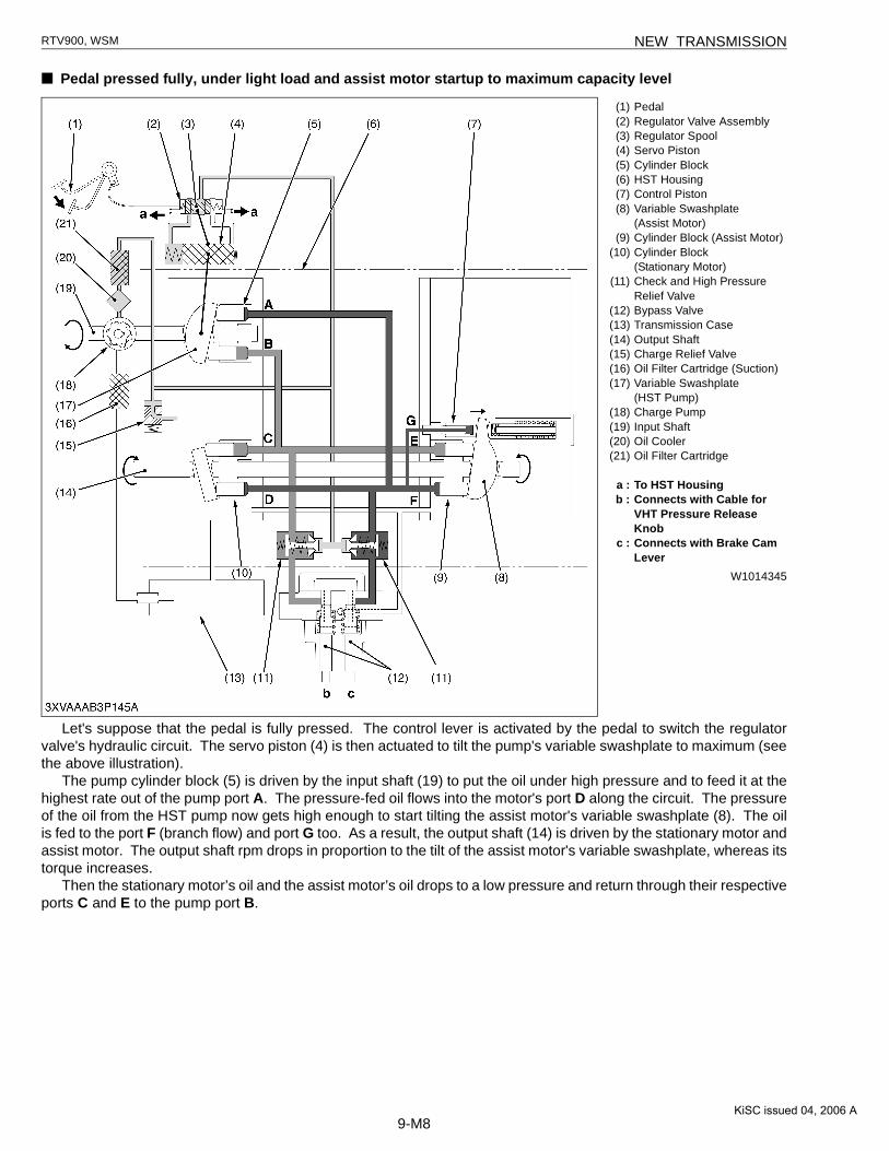
■ Pedal pressed fully, under light load and assist motor startup to maximum capacity level
W1014345
Let's suppose that the pedal is fully pressed. The control lever is activated by the pedal to switch the regulatorvalve's hydraulic circuit. The servo piston (4) is then actuated to tilt the pump's variable swashplate to maximum (seethe above illustration).
The pump cylinder block (5) is driven by the input shaft (19) to put the oil under high pressure and to feed it at thehighest rate out of the pump port A. The pressure-fed oil flows into the motor's port D along the circuit. The pressureof the oil from the HST pump now gets high enough to start tilting the assist motor's variable swashplate (8). The oilis fed to the port F (branch flow) and port G too. As a result, the output shaft (14) is driven by the stationary motor andassist motor. The output shaft rpm drops in proportion to the tilt of the assist motor's variable swashplate, whereas itstorque increases.
Then the stationary motor’s oil and the assist motor’s oil drops to a low pressure and return through their respectiveports C and E to the pump port B.
(1) Pedal(2) Regulator Valve Assembly(3) Regulator Spool(4) Servo Piston(5) Cylinder Block(6) HST Housing(7) Control Piston(8) Variable Swashplate
(Assist Motor)(9) Cylinder Block (Assist Motor)
(10) Cylinder Block(Stationary Motor)
(11) Check and High Pressure Relief Valve
(12) Bypass Valve(13) Transmission Case(14) Output Shaft(15) Charge Relief Valve(16) Oil Filter Cartridge (Suction)(17) Variable Swashplate
(HST Pump)(18) Charge Pump(19) Input Shaft(20) Oil Cooler(21) Oil Filter Cartridge
a : To HST Housingb : Connects with Cable for
VHT Pressure Release Knob
c : Connects with Brake Cam Lever
KiSC issued 04, 2006 A

9-M9
RTV900, WSM NEW TRANSMISSION
■ Pedal pressed fully, under heavy load and input horsepower control
W1014628
Let's suppose that the pedal is fully pressed. The control lever is activated by the pedal to switch the regulatorvalve's hydraulic circuit. The servo piston (4) is then actuated to tilt the pump's variable swashplate to maximum (seethe above illustration).
The pump cylinder block (5) is driven by the input shaft (19) to put the oil under high pressure and to feed it at thehighest rate out of the pump port A. The pressure-fed oil flows into the motor's port D along the circuit. The oil fromthe HST pump then reaches the pressure level 17.7 MPa (180 kgf/cm2, 2560 psi) to tilt the assist motor's variableswashplate (8) all the way. At this time, the assist motor reaches its maximum capacity.
If the load becomes heavier, the variable swashplate (pump) moves toward to the neutral position under thereaction of HST pump itself. With the variable swashplate tilted back to neutral side, the engine load becomes lighterand the engine rpm higher again. At this time, the pump's delivery rate drops, but the recovered engine rpm enablesthe delivery oil pressure to go up to the high-pressure relief valve setting. Now the maximum torque is obtained.
(1) Pedal(2) Regulator Valve Assembly(3) Regulator Spool(4) Servo Piston(5) Cylinder Block(6) HST Housing(7) Control Piston(8) Variable Swashplate
(Assist Motor)(9) Cylinder Block (Assist Motor)
(10) Cylinder Block(Stationary Motor)
(11) Check and High Pressure Relief Valve
(12) Bypass Valve(13) Transmission Case(14) Output Shaft(15) Charge Relief Valve(16) Oil Filter Cartridge (Suction)(17) Variable Swashplate
(HST Pump)(18) Charge Pump(19) Input Shaft(20) Oil Cooler(21) Oil Filter Cartridge
a : To HST Housingb : Connects with Cable for
VHT Pressure Release Knob
c : Connects with Brake Cam Lever
KiSC issued 04, 2006 A
9-M10
RTV900, WSM NEW TRANSMISSION
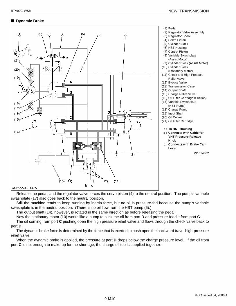
■ Dynamic Brake
W1014882
Release the pedal, and the regulator valve forces the servo piston (4) to the neutral position. The pump’s variableswashplate (17) also goes back to the neutral position.
Still the machine tends to keep running by inertia force, but no oil is pressure-fed because the pump's variableswashplate is in the neutral position. (There is no oil flow from the HST pump (5).)
The output shaft (14), however, is rotated in the same direction as before releasing the pedal.Now the stationary motor (10) works like a pump to suck the oil from port D and pressure-feed it from port C.The oil coming from port C pushing open the high pressure relief valve and flows through the check valve back to
port D.The dynamic brake force is determined by the force that is exerted to push open the backward travel high-pressure
relief valve.When the dynamic brake is applied, the pressure at port D drops below the charge pressure level. If the oil from
port C is not enough to make up for the shortage, the charge oil too is supplied together.
(1) Pedal(2) Regulator Valve Assembly(3) Regulator Spool(4) Servo Piston(5) Cylinder Block(6) HST Housing(7) Control Piston(8) Variable Swashplate
(Assist Motor)(9) Cylinder Block (Assist Motor)
(10) Cylinder Block(Stationary Motor)
(11) Check and High Pressure Relief Valve
(12) Bypass Valve(13) Transmission Case(14) Output Shaft(15) Charge Relief Valve(16) Oil Filter Cartridge (Suction)(17) Variable Swashplate
(HST Pump)(18) Charge Pump(19) Input Shaft(20) Oil Cooler(21) Oil Filter Cartridge
a : To HST Housingb : Connects with Cable for
VHT Pressure Release Knob
c : Connects with Brake Cam Lever
KiSC issued 04, 2006 A

9-M11
RTV900, WSM NEW TRANSMISSION
■ After dynamic brake, operating brake and pulling VHT pressure release knob creates a bypass circuit
W1015199
When driving, releasing the pedal to halt the vehicle places the system under the status of dynamic braking, asdescribed in the previous section.
Immediately after halting the vehicle by pressing the brake pedal, or when the deviation from neutral position ofvariable swashplate (17) is significant, a torque will exist between HST and the transmission.
Under the conditions, shifting the gears is extremely difficult because of friction in the gear box.Operating the brake and pulling the VHT pressure release knob creates a bypass circuit, which eliminates the
difference in pressures between high pressure side and low pressure side.This operation releases the torque remaining in the transmission.As a result, smooth shifting of gears is made possible.For oil flow, a loop circuit is made through a bypass valve, between C port and D port of the fixed motor. This
system makes free rotation of the output shaft (14) possible.The bypass spool c must operate in synchronization with braking, and the bypass spool b must be controlled
manually by the VHT pressure release knob.
(1) Pedal(2) Regulator Valve Assembly(3) Regulator Spool(4) Servo Piston(5) Cylinder Block(6) HST Housing(7) Control Piston(8) Variable Swashplate
(Assist Motor)(9) Cylinder Block (Assist Motor)
(10) Cylinder Block(Stationary Motor)
(11) Check and High Pressure Relief Valve
(12) Bypass Valve(13) Transmission Case(14) Output Shaft(15) Charge Relief Valve(16) Oil Filter Cartridge (Suction)(17) Variable Swashplate
(HST Pump)(18) Charge Pump(19) Input Shaft(20) Oil Cooler(21) Oil Filter Cartridge
a : To HST Housingb : Connects with Cable for
VHT Pressure Release Knob
c : Connects with Brake Cam Lever
KiSC issued 04, 2006 A
9-M12
RTV900, WSM NEW TRANSMISSION
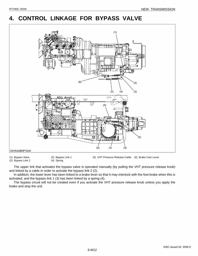
4. CONTROL LINKAGE FOR BYPASS VALVE
The upper link that activates the bypass valve is operated manually (by pulling the VHT pressure release knob)and linked by a cable in order to activate the bypass link 2 (2).
In addition, the lower lever has been linked to a brake lever so that it may interlock with the foot brake when this isactivated, and the bypass link 1 (3) has been linked by a spring (4).
The bypass circuit will not be created even if you activate the VHT pressure release knob unless you apply thebrake and stop the unit.
(1) Bypass Valve(2) Bypass Link 2
(3) Bypass Link 1(4) Spring
(5) VHT Pressure Release Cable (6) Brake Cam Lever
KiSC issued 04, 2006 A

CONTENTS
SERVICING
1. CHECKING AND ADJUSTING .....................................................................9-S12. DISASSEMBLING AND ASSEMBLING........................................................9-S2
[1] DISMOUNTING TRANSAXLE .................................................................9-S2
KiSC issued 04, 2006 A

9-S1
RTV900, WSM NEW TRANSMISSION
1. CHECKING AND ADJUSTINGChecking Brake Rod
CAUTION• When checking, park the machine on flat ground.• Work by two people when you measure pressure.1. Remove the tension spring (5) from the bypass link 2 (6).2. Remove the brake return spring (3).3. Adjust the link length using the turnbuckle (1) so that the brake
lever (2) has no play.
IMPORTANT■• After adjusting the brake rod, be sure to adjust the tension
spring (5) as well.(Adjusting procedure)1. Adjust the length of tension bolt (4) to remove allowance of the
tension spring (5). By adjusting the length of the tension bolt (4),remove allowance of the tension spring (5). (To adjust the length,the tension spring (5) must be removed from the bypass link (6)to turn the tension bolt (4).)
2. After removing allowance of the tension spring (5), remove thetension spring (5) once and rotate the tension bolt (4) clockwiseby one turn. (A slight tension is given to the tension spring (5).)
(Reference)• Turning torque of the rear axle at this time is 9.8 to 14.7 N·m (1
to 1.5 kgf·m, 7.2 to 10.8 ft-lbs).
CAUTION• Over-pulling due to poor turnbuckle adjustment can result in
the problem of brake drag (overheating and burning).
W1010622
(1) Turnbuckle (Brake Rod)(2) Brake Lever(3) Return Spring
(4) Tension Bolt(5) Tension Spring(6) Bypass Link 2
KiSC issued 04, 2006 A

9-S2
RTV900, WSM NEW TRANSMISSION
2. DISASSEMBLING AND ASSEMBLING[1] DISMOUNTING TRANSAXLE
Draining the Transmission Fluid1. Place oil pans underneath the transmission case.2. Remove the drain plug (1).3. Drain the transmission fluid.4. Reinstall the drain plug (1).(When refilling)• Fill up from filling port after removing the filling plug (2) until
reaching the upper notch on the dipstick (3).• After running the engine for few minutes, stop it and check the oil
level again, add the fluid to prescribed level if it is not correctlevel.
IMPORTANT■• Use only KUBOTA SUPER UDT fluid. Use of other oils may
damage the transmission.Refer to “LUBRICANTS, FUEL AND COOLANT”. (See pageG-1.)
• Do not mix different brands of fluid together.
W1013492
Draining Coolant
CAUTION• Never open the radiator cap while operating or immediately
after stopping. Otherwise, hot water will spout out from theradiator. Wait for more than ten minutes to cool the radiator,before opening the cap.
1. Stop the engine and let cool down.2. Remove the protective cover (4).3. Remove the radiator coolant drain plug (3) to drain the coolant.4. Remove the radiator cap (1) to completely drain the coolant.5. After all coolant is drained, close the drain plugs.
W1013915
Transmission fluid capacity10 L2.6 U.S.gals2.2 Imp.gals
(1) Drain Plug with Magnet(2) Filling Plug(3) Dipstick
A : Oil level is acceptable within this range.
Coolant capacityRadiator with recovery tank
4.0 L4.2 U.S.qts.3.5 Imp.qts.
(1) Radiator Cap(2) Recovery Tank
(3) Radiator Coolant Drain Plug(4) Protective Cover
KiSC issued 04, 2006 A

9-S3
RTV900, WSM NEW TRANSMISSION
Battery
CAUTION• When disconnecting the battery cables, disconnect the
negative cable from the battery first. When connecting,connect the positive cable to the battery first.
1. Disconnect the negative cable (1) from the battery.2. Disconnect the positive cable (2) from the battery.
W1017351
Cargo Bed1. Lift up the cargo bed (1) by hand and support it so that the
hydraulic cylinder should not drop. (If hydraulic cylinderequipped.)
2. Remove the cotter pin and clevis pin (2). (If hydraulic cylinderequipped.)
3. Disconnect the connector (3) from main harness, then separatethe harness for the tail lamps.
4. Loosen the lock nut (4) and remove the hinge bolt (5) and nut.
W1017555
(1) Negative Cable (2) Positive Cable
(1) Cargo Bed(2) Clevis Pin(3) Connector
(4) Lock Nut(5) Hinge Bolt
KiSC issued 04, 2006 A

9-S4
RTV900, WSM NEW TRANSMISSION
Muffler Cover, Muffler, Hydraulic Oil Tank, Hydraulic Cylinderand Hydraulic Control Valve1. Remove the muffler cover (1) and muffler (2).2. Disconnect the quick couplers from hydraulic control valve.3. Remove the cotter pin and clevis pin, then remove the hydraulic
cylinder (3).4. Disconnect the suction hose (4) and return hose (5), then remove
the hydraulic oil tank (6).5. Disconnect the cables (7) for hydraulic control valve.6. Disconnect the delivery hose (8) and remove the hydraulic
control valve (10).(When reassembling)• When connecting the hydraulic control valve (10) cable to
hydraulic control valve lever (9), be sure to adjust the length ofcables (7).
NOTE■• The muffler shall be assembled in the following order:
1. To secure the muffler (2) to the exhaust manifold, put fourspring lock washers on studs and start a nut (11) on eachstud. Screw each nut 2 to 3 threads on studs.
2. To secure muffler (2) to muffler stay (13), start a sems bolt(bolt with plane washer and spring lock washer. Turn semsbolt 2 to 3 threads into underside of muffler stay (13) and themuffler (2).
3. Tighten nuts (11) that fasten the muffler (2) to the exhaustmanifold (12).
4. Tighten the sems bolt that fasten the underside of themuffler (2) to the muffler stay (13) (On this occasion, checkthe gap between the undersize of the muffler and its stay.When there is a large gap between them, lift the stay andassemble the muffler. And keep them to such a position tofasten the muffler stay.).
5. Tighten the bolts (15) that fasten muffler stay (13) totransmission.
W1017697
Tightening torque
Muffler mounting nut23.6 to 27.4 N·m2.4 to 2.8 kgf·m17.4 to 20.2 ft-lbs
Muffler mounting bolt(Sems bolt)
48.1 to 55.8 N·m4.9 to 5.7 kgf·m35.5 to 41.2 ft-lbs
Muffler stay mounting bolt17.7 to 20.5 N·m1.8 to 2.1 kgf·m13.1 to 15.1 ft-lbs
(1) Muffler Cover(2) Muffler(3) Hydraulic Cylinder(4) Suction Hose(5) Return Hose(6) Hydraulic Oil Tank(7) Control Valve Cable(8) Delivery Hose
(9) Hydraulic Control Valve Lever(10) Hydraulic Control Valve(11) Nut(12) Exhaust Manifold(13) Muffler Stay(14) Sems Bolt(15) Bolt
KiSC issued 04, 2006 A

9-S5
RTV900, WSM NEW TRANSMISSION
Air Cleaner, Wire Harness, Radiator Hose (Upper), Cables andBrake Cylinder1. Remove the air cleaner body and intake hose as a unit.2. Disconnect the wire harness (1) from engine, alternator and
stator motor.3. Remove the ground cable (5) and positive cable (4).4. Disconnect the parking brake cables (8), four wheel drive cable
(10), select cable and shift cable (2).5. Remove the speed control pedal cable (9).6. Remove the clevis pin and the brake cylinder (7) with brake rod.7. Disconnect the differential lock cable (6).8. Remove the radiator upper hose (3).(When reassembling)• Adjust the length of the shift cable and select cable. (See page
2-S14.)• Adjust the length of the speed control pedal cable. (See page 2-
S13.)• Adjust the length of the parking brake cable. (See page 2-S16.)• Adjust the length of the 4WD shift cable. (See page 2-S15.)
W1013611
(1) Wire Harness(2) Shift Cable and Select Cable(3) Radiator Upper Hose(4) Positive Cable(5) Ground Cable
(6) Differential Lock Cable(7) Brake Cylinder(8) Parking Brake Cable(9) Speed Control Pedal
(10) 4WD Cable
KiSC issued 04, 2006 A

9-S6
RTV900, WSM NEW TRANSMISSION
VHT Pressure Release Cable1. Loosen the lock nut (2) and remove the VHT pressure release
cable (1) from the bypass link 1 (3).(When reassembling)
NOTE■• When adjusting the cable tension, take care not to apply
excessive tension.• Adjust the length of the cable outer section so that the cable
(1) has no play, and tighten the lock nut.
W1014737
Tension Spring of VHT Pressure Release Link1. Remove the tension spring (4) from the bypass link 2 (5).2. Remove the clevis (2) from brake cam lever (1).(When reassembling)
NOTE■• Before adjusting the tension spring (4), be sure to complete
adjustment of the brake rod.• Adjust the length of tension bolt (3) to remove allowance of
the tension spring (4). By adjusting the length of the tensionbolt (3), remove allowance of the tension spring (4). (Toadjust the length, the tension spring (4) must be removedfrom the link to turn the tension bolt (3).)
• After removing allowance of the tension spring (4), removethe tension spring (4) once and rotate the bolt clockwise byone turn. (A slight tension is given to the tension spring (4).)
W1014583
Power Steering Hose and Radiator Hose (Lower)1. Remove the power steering suction hose (3) and delivery hose
(4).2. Disconnect the fuel hose (2).3. Disconnect the radiator hose (lower) (1).
W1015069
(1) VHT Pressure Release Cable(2) Lock Nut
(3) Bypass Link 1
(1) Brake Cam Lever(2) Clevis(3) Tension Bolt
(4) Tension Spring(5) Bypass Link 2
(1) Radiator Hose (Lower)(2) Fuel Hose
(3) Suction Hose(4) Delivery Hose
KiSC issued 04, 2006 A

9-S7
RTV900, WSM NEW TRANSMISSION
Rear Axle Bracket1. Remove the boot band (2) on both sides.2. Place the stand under the both side of frame.3. Remove the rear wheels.4. Remove the leaf spring mounting bolt (1) and nut, and remove
the rear axle bracket assembly (3) by use the axle support (4).(When reassembling)• Align the master spline of propeller shaft and rear axle shaft.• Replace the boot band with new one.
W1018767
Tightening torque
Leaf spring mounting bolt and nut
48.0 to 56.6 N·m4.9 to 5.7 kgf·m35.4 to 41.3 ft-lbs
Rear wheel mounting screw
75.0 to 90.0 N·m7.6 to 9.2 kgf·m55.3 to 66.4 ft-lbs
(1) Leaf Spring Mounting Bolt(2) Boot Band
(3) Rear Axle Bracket Assembly(4) Axle Support
KiSC issued 04, 2006 A

9-S8
RTV900, WSM NEW TRANSMISSION
Dismounting Transmission and Engine One Piece Assembly1. Remove the universal joint mounting screw and disconnect the
universal joint (4) from transmission.2. Set the power train support (5) and remove the mission frame (3)
mounting bolt (2) and nut.3. Lift up the main frame by hoist.4. Remove the transmission and engine one piece assembly (4).(When reassembling)• Align the master spline (A) of 4WD propeller shaft and universal
joint.• The bolt can be put through the rubber bushing more easily if
soap water is applied to the bolt. Never hit the bolt.• Assemble the mission frame in such a manner as to insert two
bolts in the front and then two bolts in the rear, instead ofinserting the four bolts at a time.
• When reassembling the transmission and engine one pieceassembly (mission frame) into the main frame, do not forget toassemble the 4WD propeller shaft (1) with universal joint (4) aswell.
• Apply grease to splines of 4WD propeller shaft (1) and splines ofuniversal joint (4).
W1015698
Power Steering Hose and Radiator Hose (Lower)Here after, refer to WSM No. 97897-15320 of RTV900, which
serves as basis.W1018519
Tightening torque
Mission frame mounting bolt and nut
29.4 to 49.0 N·m3.0 to 5.0 kgf·m21.7 to 36.1 ft-lbs
Universal joint mounting screw
23.6 to 27.4 N·m2.4 to 2.8 kgf·m17.4 to 20.2 ft-lbs
(1) 4WD Propeller Shaft(2) Mission Frame Mounting Bolt(3) Mission Frame(4) Universal Joint
(5) Transmission and Engine One Piece Assembly
(6) Power Train Support
(A) Master Spline
KiSC issued 04, 2006 A

Printed in Japan 2006. 04, S, EI, EI, e Code No.9Y011-15630KUBOTA Corporation
EDITOR:KUBOTA FARM & INDUSTRIAL MACHINERY SERVICE, LTD.64, ISHIZU-KITAMACHI, SAKAI-KU, SAKAI-CITY, OSAKA, 590-0823, JAPANPHONE : (81)72-241-1129FAX : (81)72-245-2484E-mail : [email protected]