rule based matrix formulation structure€¦ · · 2017-12-14avoidance dispatching, ... x is the...
TRANSCRIPT
Deadlock Analysis and Routing on Free-Choice MFlow Lines Using a Matrix-Based Discrete Ev
Jose Mireles Jr1, Member IEEE, and Frank L. Lewis2
1Instituto de Ingeniería y Tecnología de la Universidad AutónomAve. del Charro 610 Nte. Juárez MÉXICO.
2Automation & Robotics Research Institute, of The University of Te7300 Jack Newell Blvd. S., Fort Worth, TX 76118-7115
E-mails: [email protected], [email protected].
Abstract. We present an analysis for deadlock avoidance in manufacturing
Flow-lines (FMRF). In FMRF, shared resources are not dedicated for certain jobs;
choices in reentrant flow lines, i.e. routing decisions to be made. A Discrete Ev
avoidance dispatching, which framework uses a rule-based matrix formulation, is u
systems. The development of deadlock-free dispatching rules is derived from circu
blocking situations. We analyze the so-called critical siphons, and certain critical
develop deadlock-free dispatching. The DE controller guaranties deadlock av
progress in the critical subsystems associated with each CW. This is the least-
avoids deadlock. In this paper, we calculate in matrix form all constructions n
controllers using online-deadlock-free dispatching rules, for the case of regular FM
Keywords: Deadlock Avoidance, Petri nets, Discrete Event Systems, Reentrant flow
1 Introduction
The use of shared resources to sequence machine jobs is a major pro
Discrete Event Systems (DES) or Flexible Manufacturing Systems [Buz
resources manipulate or machine single parts in a DES, others manipulate
several products in the manufacturing process. It is even harder when DE
choice) reentrant flow lines where no jobs have predetermined resources ass
dispatching decisions are needed. If the assignments of resources for specifi
sequenced, serious problems in the performance of the DES can be obta
blocking and system deadlock [Banaszak et al. 90, Hsieh et al. 94, Kumar
Jeng et al. 95, Huang et al. 96, Xing et al. 96, Fanti et al. 00, Lewis et a
blocking develops in a circular wait [Wysk et al. 91, Hyenbo et al. 95] situa
* Research supported by ARO Grants DAAD19-00-1-0037, and DAAD19-99-1-0137 fromMejoramiento del Profesorado (PROMEP) from México.
CDC02-REG0071
ultipart Reentrantent Controller*
, Fellow IEEE.
a de Ciudad Juárez,
xas at Arlington (UTA) , USA. edu
Free-choice Multipart Reentrant
some jobs have multiple resource
ent (DE) supervisor for deadlock
sed for routing/dispatching FMRF
lar wait (CW) analysis for possible
subsystems on FMRF systems to
oidance by limiting the work-in-
restrictive dispatching policy that
eeded for implementation of DE
RF systems.
lines, Intelligent control.
blem in the implementation of
acott et al. 86]. While some
or machine multiple parts for
S have multiple choice (or free
igned. Then, routing as well as
c machine jobs are not correctly
ined. These problems include
an et al. 94, Ezpeleta et al. 95,
l. 98]. Deadlock occurs when
tion, which is a fatal condition
1
U.S.A, and by Programa de

that eventually stops all activity in the flow lines involved. Therefore, it is very important that the DE
controller properly sequences jobs and assigns resources.
Little rigorous work has been done for dispatching in Multipart Reentrant Flow-lines (MRF) with finite
buffers. However, we have shown in [Mireles et al. 02] analysis of constructions needed for deadlock-free
dispatching on these MRF systems. These constructions are calculated in matrix form for efficient real time
control. But, due to the added dispatching routing alternative on Free-Choice MRF (FMRF) systems, the
constructions developed for deadlock avoidance on MRF systems are not valid. Also, all references
mentioned above are for reentrant flow lines with no routing. In this paper we provide an analysis of
constructions needed for FMRF systems, by showing an analogy over MRF systems.
We show how to analize and compute in matrix notation the constructions needed for deadlock
avoidance in a cretain large class of “regular” FMRF systems with routing. We extend to systems with
routing the notions of circular waits, their critical siphons, and certain critical subsystems. Regular systems
do not contain Critical Resources (CR) or key resources [Gurel et al. 00]. These CR are critical structured-
placed resources that migh lead to Second Level Deadlock (SLD) [Fanti et al. 97] situations in MRF/FMRF
systems. Deadlock avoidance is performed on regular FMRF systems by restricting the work-in-progress
(WIP) in certain “critical subsystems.” This is a rigorous notion related to the idea of ‘CONWIP’
[Spearman et al. 90]. All computations are performed using straightforward matrix algorithms, including
computation of these critical subsystems, for any FMRF in a certain general class, regular systems [Gurel et.
al. 00]. We demonstrate that this matrix formulation is computationally efficient for control of FMRF
systems.
2 Matrix-Based Discrete Event Controller
A Discrete Event Controller (DEC) for manufacturing workcells was described in [Lewis et al. 93a-94b,
Pastravanu et al. 94a, Tacconi et al. 97, Mireles et al. 01a-b]. This DEC is based on matrices, and it was
shown to have important advantages in design, flexibility and computer simulation. The framework of the
Discrete Event Controller is described as follows. Let v be the set of tasks or jobs used in the system, r the
set of resources that implement/perform the tasks, u the set of inputs or parts entering the DES. The DEC
Model State Equation is described as
Cucurv uFuFrFvFx ⊗⊕⊗⊕⊗⊕⊗= (1) where:
x is the task or state logical vector,
is the job sequencing matrix, vF
2
is the resource requirements matrix, rF
is the input matrix, uF
is the conflict resolution matrix, and ucF
uc is a conflict resolution vector.
This DEC equation is performed in the AND/OR algebra. That is, multiplication represents logical
“AND,” addition represents logical “OR,” and the over-bar means logical negation (used as in
[Pastravanu et al. 94].) The job sequencing matrix F
⊗
⊕
Cu
v reflects the states to be launched based on the current
finished jobs. The resource requirement matrix Fr represents the set of resources needed to fire possible job
states this is the matrix used by [Kusiak et al. 91-92]. The input matrix Fu determines initial states fired
from the input parts. The conflict resolution matrix Fuc prioritizes states launched from the external
dispatching input , which has to be derived via some decision making algorithm [Panwalkar et al. 77,
Graves 81, Mireles et al. 01]. For the case of FMRF systems, Least Slack dispatching policies need to be
considered for appropriate routings [Kumar 93,94].
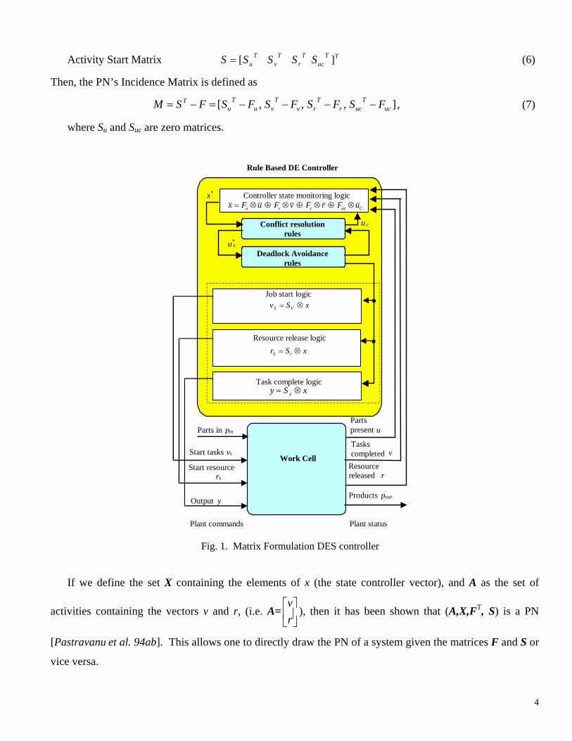
For a complete DEC formulation, one must introduce additional matrices, Sr and Sv, as described next.
The state logic obtained from the state equation is used to calculate the jobs to be fired (or task commands),
to release resources, and to inform about the final products produced by the system. These three important
features are obtained by using the three equations:
Start Equation (task commands) xSv VS ⊗= (2)
Resource Release Equation xSr rS ⊗= (3)
Product Output Equation xSy y ⊗= (4)
Fig. 1 shows the DEC based on the matrix formulation as used to control job sequences and resource
assignment of a workcell. Subscript “s” on the vectors v and r denotes “start.” Thus, v and r are outputs
from the workcell measured by sensors, while vs and rs are commands to the workcell to begin jobs or set
resources as “released.”
2.1 Matrix Formulation and Petri-Nets
There is a very close relationship between the DEC just described and Petri Net (PN) tools [Murata 89,
Peterson 81, Zhou et al. 92-93]. The Incidence Matrix [Peterson 81] of the PN equivalent to the DE
controller is obtained by defining the activity completion matrix and the activity start matrix as:
Activity Completion Matrix ][ ucrvu FFFFF = (5)
3
Activity Start Matrix (6) TTuc
Tr
Tv
Tu SSSSS ][=
Then, the PN’s Incidence Matrix is defined as
],,,[ ucT
ucrT
rvT
vuT
uT FSFSFSFSFSM −−−−=−= , (7)
where Su and Suc are zero matrices.
Tasks completed v
Rule Based DE Controller
Cucrvu uFrFvFuFx ⊗⊕⊗⊕⊗⊕⊗=
Job start logic
Resource release logic
Work Cell
.
.
u*c
Parts present u
Resourcereleased r
Parts in p inStart tasks v sStart resource
r s Output y Products pout
Plant commands Plant status
Controller state monitoring logic
xSv VS ⊗=
xSr rS ⊗=
xSy y ⊗=Task complete logic
Conflict resolution rules
x*
uc
Deadlock Avoidance rules
Fig. 1. Matrix Formulation DES controller
If we define the set X containing the elements of x (the state controller vector), and A as the set of
activities containing the vectors v and r, (i.e. A= ), then it has been shown that (A,X,F
rv T, S) is a PN
[Pastravanu et al. 94ab]. This allows one to directly draw the PN of a system given the matrices F and S or
vice versa.
4

If the marking vector m(t) from a PN is defined as
m(t) = [ ]Tc
TTT tutrtvtu )(,)(,)(,)( T. (8)
For a specific time iteration t, then the PN marking transition equation [Peterson 81] is
. (9) )(][)()()1( txFStmxMtmtm TT −+=+=+
2.2 Complete Dynamical Description for DES
A major gap in PN theory has been its inability to provide a complete dynamical description of a DES.
The marking transition equation (9) provides a partial description [Peterson 81], but it is not known in the
literature how to generate the allowable firing vector x(t). This deficiency is repaired by using the matrix-
based DEC controller equation (1) together with the PN marking transition equation. The key is to note that
the vector x(t) in (9) is identical to the vector x in the DEC equation (1) at time t.
To put the DEC eqs. into a format convenient for simulation, one may write (1) as mFx ⊗= or
)(][][)()( turvuFFFFtmFtx cucrvu ⊕=⊕= (10)
The complete dynamical description of the DES, as described in [Mireles et al. 01], is provided by the
PN marking eq. (9), plus the DEC equation (10). Note that we are using the Timed Places Petri Net
(TPPN) representation of PNs [López-Mellado 95].
A complete development of an implementation and simulations using this DE supervisor/framework is
provided in [Mireles et al. 01].
3 Matrix Analysis of FMRF Systems with routing: Internal Deadlock Constructions
In this section we show analysis of deadlock structures using matrices for reentrant flowlines with
routing. These constructions yield computationally efficient algorithms for deadlock-free dispatching of
FMRF systems. Least restrictive deadlock-free policies are given in Section 4. In Section 5, we show an
example illustrating the formulation of these constructions.
Consider the definition of Multiple Reentrant Flow-lines (MRF1) and the assumptions considered in
[Gurel et.al 00], which basically define the sort of discrete-part manufacturing systems that can be described
by a Petri net. The assumptions are:
• We assume there are no machine failures.
• No preemption. A resource cannot be removed from a job until it is complete.
• Mutual exclusion. A single resource can be used for only one job at a time.
5
• Hold while waiting. A process holds the resources already allocated to it until it has all resources
required to perform a job.
• After each resource executes one job, it is released immediately.
In addition to this assumptions, and since we consider having a Free-Choice Multipart Reentrant Flow-Line,
we got the non-restrictive capability that
• Some jobs have the option of been machined in one resource from a set of resources (routing of
jobs), and each resource might be used for different jobs (shared resources.)
• Job/part routings are deterministic and are provided by a dynamic controller.
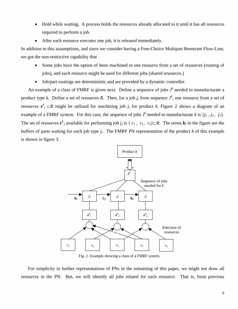
An example of a class of FMRF is given next. Define a sequence of jobs Jk needed to manufacturate a
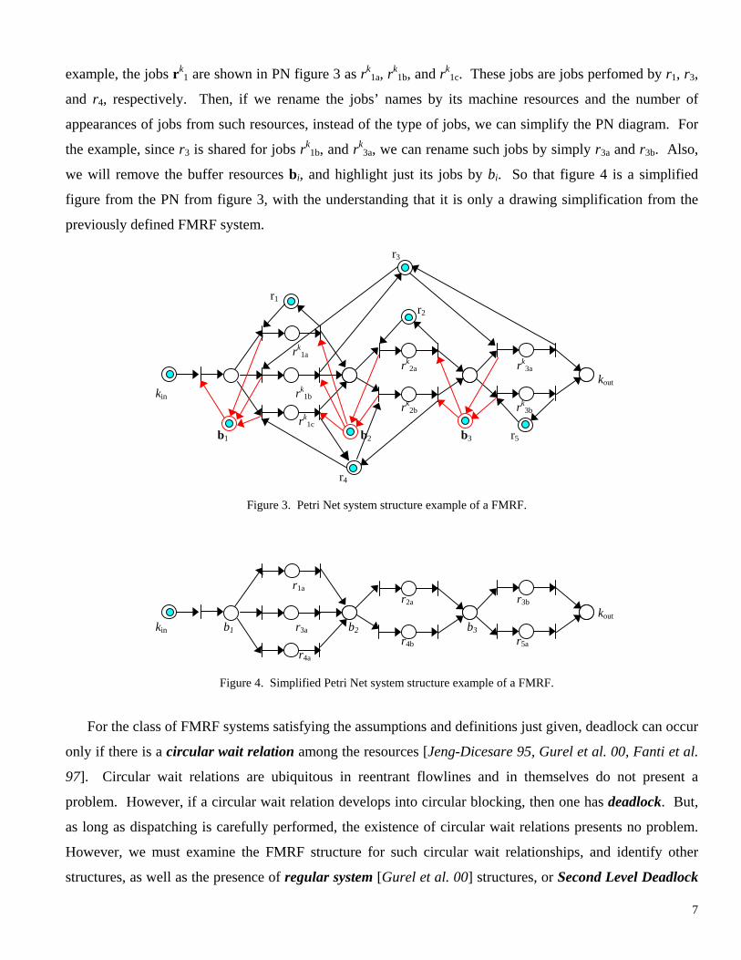
product type k. Define a set of resources R. Then, for a job ji from sequence Jk, one resource from a set of
resources rki ⊂R might be utilized for machining job ji for product k. Figure 2 shows a diagram of an
example of a FMRF system. For this case, the sequence of jobs Jk needed to manufacturate k is {j1 , j2 , j3}.
The set of resources rk1 available for performing job j1 is { r1 , r3 , r4}⊂R. The terms bi in the figure are the
buffers of parts waiting for each job type ji. The FMRF PN representation of the product k of this example
is shown in figure 3.
Selection of resources
r5
b3b2b1
rk3
rk2
j3
j2
j1
Jk
r4
rk1
r3
r2
r1
Product k
Sequence of jobs needed for k
Fig. 2. Example showing a class of a FMRF system.
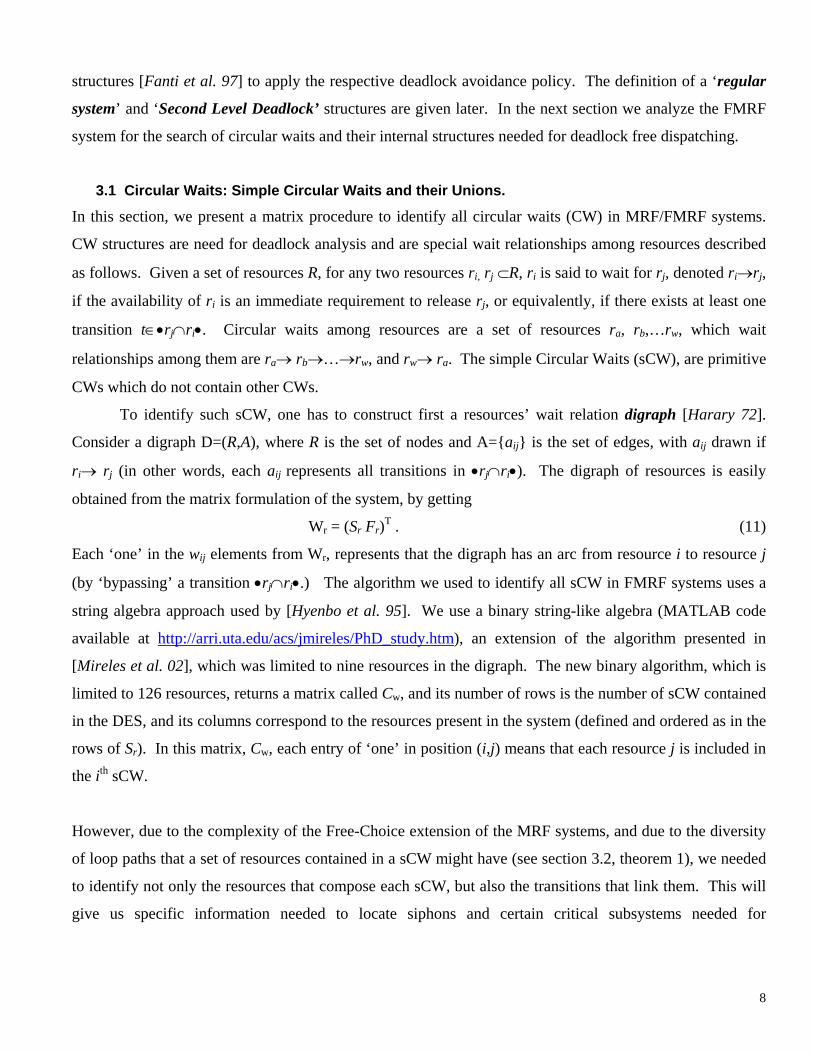
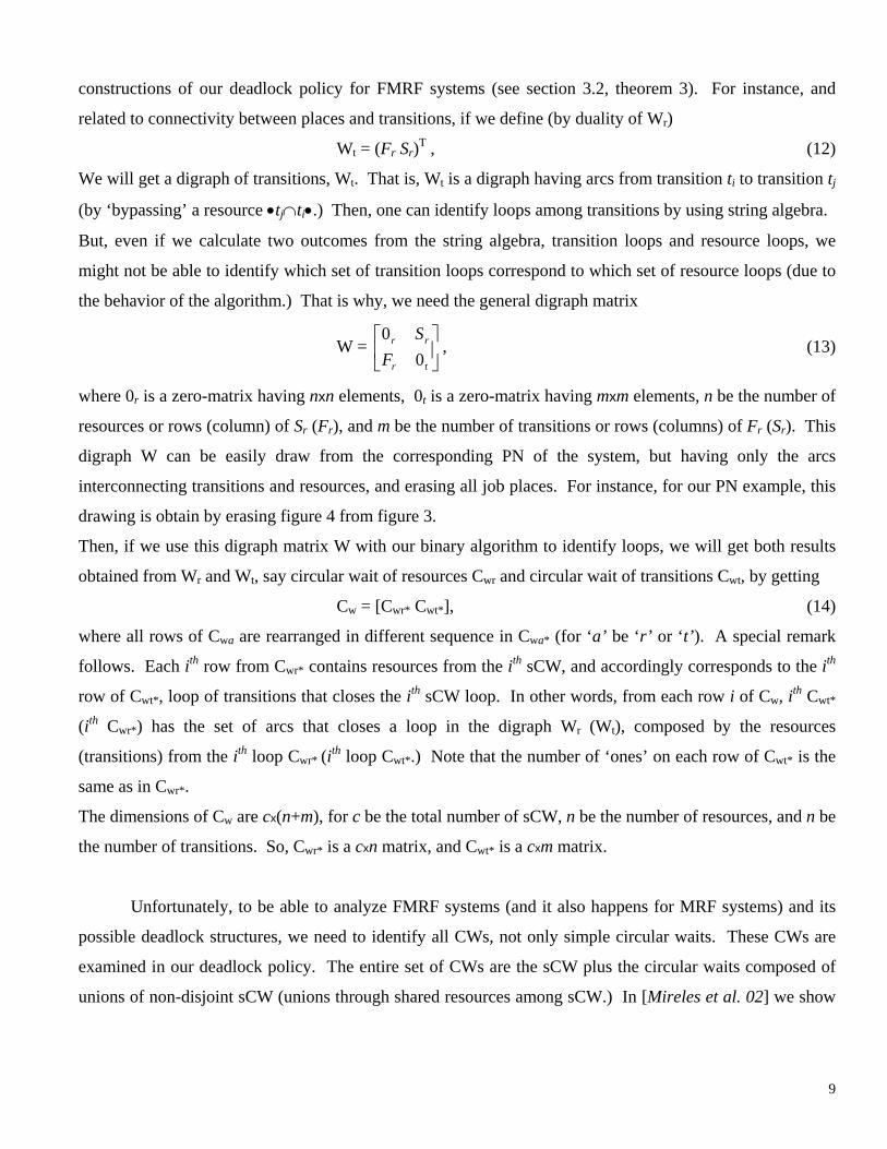
For simplicity in further representations of PNs in the remaining of this paper, we might not draw all
resources in the PN. But, we will identify all jobs related for each resource. That is, from previous
6
example, the jobs rk1 are shown in PN figure 3 as rk
1a, rk1b, and rk
1c. These jobs are jobs perfomed by r1, r3,
and r4, respectively. Then, if we rename the jobs’ names by its machine resources and the number of
appearances of jobs from such resources, instead of the type of jobs, we can simplify the PN diagram. For
the example, since r3 is shared for jobs rk1b, and rk
3a, we can rename such jobs by simply r3a and r3b. Also,
we will remove the buffer resources bi, and highlight just its jobs by bi. So that figure 4 is a simplified
figure from the PN from figure 3, with the understanding that it is only a drawing simplification from the
previously defined FMRF system.
r3 r1 r2 rk
1a rk
2a rk3a
koutkin rk
1b rk
2b rk3b
rk1c
b1 b2 b3 r5 r4
Figure 3. Petri Net system structure example of a FMRF.
r1a r2a r3b koutkin b1 r3a b2 b3 r4b r5a r4a
Figure 4. Simplified Petri Net system structure example of a FMRF.
For the class of FMRF systems satisfying the assumptions and definitions just given, deadlock can occur
only if there is a circular wait relation among the resources [Jeng-Dicesare 95, Gurel et al. 00, Fanti et al.
97]. Circular wait relations are ubiquitous in reentrant flowlines and in themselves do not present a
problem. However, if a circular wait relation develops into circular blocking, then one has deadlock. But,
as long as dispatching is carefully performed, the existence of circular wait relations presents no problem.
However, we must examine the FMRF structure for such circular wait relationships, and identify other
structures, as well as the presence of regular system [Gurel et al. 00] structures, or Second Level Deadlock
7
structures [Fanti et al. 97] to apply the respective deadlock avoidance policy. The definition of a ‘regular
system’ and ‘Second Level Deadlock’ structures are given later. In the next section we analyze the FMRF
system for the search of circular waits and their internal structures needed for deadlock free dispatching.
3.1 Circular Waits: Simple Circular Waits and their Unions.
In this section, we present a matrix procedure to identify all circular waits (CW) in MRF/FMRF systems.
CW structures are need for deadlock analysis and are special wait relationships among resources described
as follows. Given a set of resources R, for any two resources ri, rj ⊂R, ri is said to wait for rj, denoted ri→rj,
if the availability of ri is an immediate requirement to release rj, or equivalently, if there exists at least one
transition t∈•rj∩ri•. Circular waits among resources are a set of resources ra, rb,…rw, which wait
relationships among them are ra→ rb→…→rw, and rw→ ra. The simple Circular Waits (sCW), are primitive
CWs which do not contain other CWs.
To identify such sCW, one has to construct first a resources’ wait relation digraph [Harary 72].
Consider a digraph D=(R,A), where R is the set of nodes and A={aij} is the set of edges, with aij drawn if
ri→ rj (in other words, each aij represents all transitions in •rj∩ri•). The digraph of resources is easily
obtained from the matrix formulation of the system, by getting
Wr = (Sr Fr)T . (11)
Each ‘one’ in the wij elements from Wr, represents that the digraph has an arc from resource i to resource j
(by ‘bypassing’ a transition •rj∩ri•.) The algorithm we used to identify all sCW in FMRF systems uses a
string algebra approach used by [Hyenbo et al. 95]. We use a binary string-like algebra (MATLAB code
available at http://arri.uta.edu/acs/jmireles/PhD_study.htm), an extension of the algorithm presented in
[Mireles et al. 02], which was limited to nine resources in the digraph. The new binary algorithm, which is
limited to 126 resources, returns a matrix called Cw, and its number of rows is the number of sCW contained
in the DES, and its columns correspond to the resources present in the system (defined and ordered as in the
rows of Sr). In this matrix, Cw, each entry of ‘one’ in position (i,j) means that each resource j is included in
the ith sCW.
However, due to the complexity of the Free-Choice extension of the MRF systems, and due to the diversity
of loop paths that a set of resources contained in a sCW might have (see section 3.2, theorem 1), we needed
to identify not only the resources that compose each sCW, but also the transitions that link them. This will
give us specific information needed to locate siphons and certain critical subsystems needed for
8
constructions of our deadlock policy for FMRF systems (see section 3.2, theorem 3). For instance, and
related to connectivity between places and transitions, if we define (by duality of Wr)
Wt = (Fr Sr)T , (12)
We will get a digraph of transitions, Wt. That is, Wt is a digraph having arcs from transition ti to transition tj
(by ‘bypassing’ a resource •tj∩ti•.) Then, one can identify loops among transitions by using string algebra.
But, even if we calculate two outcomes from the string algebra, transition loops and resource loops, we
might not be able to identify which set of transition loops correspond to which set of resource loops (due to
the behavior of the algorithm.) That is why, we need the general digraph matrix
W = , (13)
tr
rr
FS0
0
where 0r is a zero-matrix having nxn elements, 0t is a zero-matrix having mxm elements, n be the number of
resources or rows (column) of Sr (Fr), and m be the number of transitions or rows (columns) of Fr (Sr). This
digraph W can be easily draw from the corresponding PN of the system, but having only the arcs
interconnecting transitions and resources, and erasing all job places. For instance, for our PN example, this
drawing is obtain by erasing figure 4 from figure 3.
Then, if we use this digraph matrix W with our binary algorithm to identify loops, we will get both results
obtained from Wr and Wt, say circular wait of resources Cwr and circular wait of transitions Cwt, by getting
Cw = [Cwr* Cwt*], (14)
where all rows of Cwa are rearranged in different sequence in Cwa* (for ‘a’ be ‘r’ or ‘t’). A special remark
follows. Each ith row from Cwr* contains resources from the ith sCW, and accordingly corresponds to the ith
row of Cwt*, loop of transitions that closes the ith sCW loop. In other words, from each row i of Cw, ith Cwt*
(ith Cwr*) has the set of arcs that closes a loop in the digraph Wr (Wt), composed by the resources
(transitions) from the ith loop Cwr* (ith loop Cwt*.) Note that the number of ‘ones’ on each row of Cwt* is the
same as in Cwr*.
The dimensions of Cw are cx(n+m), for c be the total number of sCW, n be the number of resources, and n be
the number of transitions. So, Cwr* is a cxn matrix, and Cwt* is a cxm matrix.
Unfortunately, to be able to analyze FMRF systems (and it also happens for MRF systems) and its
possible deadlock structures, we need to identify all CWs, not only simple circular waits. These CWs are
examined in our deadlock policy. The entire set of CWs are the sCW plus the circular waits composed of
unions of non-disjoint sCW (unions through shared resources among sCW.) In [Mireles et al. 02] we show
9
code that calculates all CWs from the sets of all sCW; it uses a Gurel’s algorithm (from [Lewis et al. 98]) in
matrix form for efficiency of computations.
Using this code, we obtain two resulting matrices, Cout and G. Cout provides the set of resources which
compose every CW (in rows), that is, an entry of ‘one’ on every (i,j) position means that resource j is
included in the ith CW. G provides the set of composed CWs (rows) from unions of sCW (columns), that is,
an entry of ‘one’ on every (i,j) position means that jth sCW is included in the ith composed CW. Then, to
calculate the set of loop resources and loop transitions included on each CW, we use the following
constructions
CWr = GT Cwr*, and (15)
CWt = GT Cwt*. (16)
CWr and CWt correspond to each other. That is, every ith row from CWr contains the CW of resources
(ordered in its columns) correspond to the CW of transitions (columns) from the ith row from CWt. Since
deadlock situations are highly associated with circular waits of resources, we will refer in subsequent
sections of the paper to CW as the loops CWr, unless specifically referred to CWt loops.
3.2 Deadlock Analysis for Routing Systems: Critical Siphons and Critical Subsystems.
In this section, we apply PN and matrix-based notions to calculate specific PN-place sets associated with
each CW. The determination of these sets is required so that we can identify possible circular blocking
(CB) [Ezpeleta et al. 95, Xing et al. 96, Lewis et al. 98, Gurel et al. 00] phenomena or deadlock situations.
After computing the sets, we will provide computationally efficient matrix-based algorithms for a least
restrictive deadlock-free dispatching policy in section 4.
These PN-place sets are highly tied to siphons associated with each CW. A siphon set has a behavioral
property that if it is token-free under some marking, then it will remain token-free under each successor
marking. Such property may leads to CB, i.e. deadlock. A set of places S is a siphon if and only if for all
places pi∈S one has • pi⊂Uj{pi• } for some {pj}⊂S.
Three important sets associated with the CW C are the siphon-job sets, Js(C), the critical siphons, Sc(C),
and critical subsystems, Jo(C). The critical siphon of a CW is the smallest siphon containing the CW. Note
that if the critical siphon ever becomes empty, the CW can never again receive any tokens. This is, the CW
has become a circular blocking. The siphon-job set, Js(C), is the set of jobs which, when added to the set of
resources contained in CW C, yields the critical siphon. The critical siphons of that CW C are the
conjunction of sets Js(C) and C. The critical subsystems of the CW C, are the job sets J(C) from that C not
contained in the siphon-job set Js(C) of C. That is Jo(C)= J(C)\ Js(C). The job sets of CW C are defined by
J(C) = ∪r∈C J(r), for J(r)=r••∩J, where J is the set of all jobs.
10

We now provide computational tools to determine the siphon-job sets Js(C), the critical siphons, Sc(C),
and critical subsystems, Jo(C), for every CW C. To determine such sets, we need to calculate the set of
adding transitions CW\TC C•+ = t, clearing transitions T CW\C•− =C
NC
t, and neutral transitions ∩ .
is the set of transitions that, when fired, add tokens to the CW C. On the contrary, is the set of
transitions which, when fired, subtract tokens from C. T is the set of transitions external to CW
NCT =
−C
+CT −
CT
+CT T
t that,
when fired, do not add or subtract transitions from C, just move tokens in C. are the set of input
and output transitions from C. These sets of transitions are important in keeping real-time track of the
tokens inside every CW, and hence in determining the status of tokens inside the critical siphon.
•• CC and
In order to implement efficient real-time control of the DES, we need to compute these sets in matrix form.
Then, we need to determine for each CW C, quantities in matrix form, which are needed for
calculation of the adding and clearing transitions. In matrix form, quantities are denoted as
•• CC and
•• CC and dC
and Cd respectively, computed as
dC = Cout Sr, and (17)
Cd = Cout FrT . (18)
Now, we are able to calculate the adding transitions CW\TC C•+ = t in matrix form
Tp = dC – (dC∧CWt), (19)
the clearing transitions CW\TC•− =C t in matrix form
Tm =Cd – (Cd ∧CWt), (20)
And the neutral transitions ∩ in matrix form NCT = +
CT −CT
Tn = Tm ∧Tp (21)
where operation A∧B represents an element-by-element logical AND operation between matrices A and B.
For each circular wait, these matrix forms contain the set of transition vectors and T arranged
in the rows of matrices T
+CT , −
CT NC
p , Tm, and Tn respectively. That is, an entry of ‘one’ on every (i,j) position in
matrix Tp (Tm, Tn), means that jth transition is a T , ) transition belonging to that i+CT ( −
CN
CT th (row set from
the) composed CW.
11
In terms of these constructions, matrix form sets are described next, indicating ‘one’ on every entry
(i,j) for places that belong to that set existing in every ith CW. The job sets described earlier for each CW C,
J(C), in matrix form are described by
JC = dC Fv = Cd . (22) TvS
The siphon-job sets for MRF systems are defined for each ith CW Ci as Js(Ci):= J(Ci) ∩ . In matrix
notation, for MRF systems, this set is found by
+•CT
JsMRF = Tp Fv. (23)
Also, for the case of MRF systems, a shortcut matrix formula for the calculation of the siphon-job sets in
matrix form, without calculating Tp is provided in [Mireles et al. 02], and it is
Js = JC ∧ )( d vFC . (24)
However, for FMRF systems, the formula (23) is not valid for some cases. The following two theorems
show the reason and cases where (23) is not a valid siphon-set for FMRF systems.
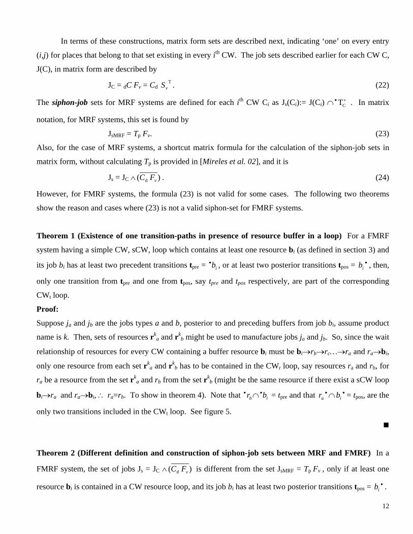
Theorem 1 (Existence of one transition-paths in presence of resource buffer in a loop) For a FMRF
system having a simple CW, sCW, loop which contains at least one resource bi (as defined in section 3) and
its job bi has at least two precedent transitions tpre = , or at least two posterior transitions tib•pos = b , then,
only one transition from t
•i
pre and one from tpos, say tpre and tpos respectively, are part of the corresponding
CWt loop.
Proof:
Suppose ja and jb are the jobs types a and b, posterior to and preceding buffers from job bi, assume product
name is k. Then, sets of resources rka and rk
b might be used to manufacture jobs ja and jb. So, since the wait
relationship of resources for every CW containing a buffer resource bi must be bi→rb→rc…→ra and ra→bi,
only one resource from each set rka and rk
b has to be contained in the CWr loop, say resources ra and rb, for
ra be a resource from the set rka and rb from the set rk
b (might be the same resource if there exist a sCW loop
bi→ra and ra→bi, ∴ ra=rb. To show in theorem 4). Note that • ∩ = tbr ib•pre and that ∩b = t•
ar•
i pos, are the
only two transitions included in the CWt loop. See figure 5.
!
Theorem 2 (Different definition and construction of siphon-job sets between MRF and FMRF) In a
FMRF system, the set of jobs Js = JC ∧ )d vFC( is different from the set JsMRF = Tp Fv , only if at least one
resource bi is contained in a CW resource loop, and its job bi has at least two posterior transitions tpos = b . •i
12
Proof:
From the definition of set of jobs Js, Cd only includes only one of the transitions from tpos, since it was
proved in theorem 1 that loop path CWr passes by only one transition from the set tpos, say this transition is
tpos. With at least this transition, is excluded from the set Jib s. However, from the definition of JsMRF, the
remaining excluded transition(s) from the set tpos, say texc (or texc for the case of tpos having only two
transitions) are Tp transitions, since any texc ⊂• bi. This means that bi is wrongly included in the set JsMRF,
and correctly excluded from Js. See figure 6.
!
bi loop : tpre tpos jb ja
: bi tpre texc texc : tpos
Figure 6. Help figure for theorem 2.
bi CW loop
ra : tpos jb ja
bi tpre rb tpre tpos
Figure 5. Help figure for theorem 1.
Therefore, (24) must be used for calculating siphon-job sets in FMRF systems, and avoid wrong
calculation of the constructions needed for our deadlock avoidance policy, such constructions are described
next.
The critical subsystems is a set of jobs used for deadlock avoidance policies (section 4) in CW
structures. These jobs are the p-invariant [Lewis et al. 98] covering job sets, not belonging to the critical
siphons job set from a specific CW. This set is defined for MRF systems as Jo(Ci) = J(Ci)\ Js(Ci), for all
CWs, Ci. In matrix form, this set is obtained by
JoMRF = JC ∧ . (25) )( d vFC
However, for the complex routing FMRF systems, this equation is not valid. The general definition Jo(Ci)
must be particularized for FMRF systems. The proper formulation of sets Jo for FMRF systems is Jo(Ci) =
CW•t∩J(Ci), for all corresponding loops CWr, Ci (loop i identified by row ith of CWr.) The matrix form of
Jo(Ci) is obtained from row ith of
Jo = CWt Fv. (26)
Notice that for FMRF systems, • CWt ⊂ {J(Ci)\ Js(Ci)}. The following theorem explains the reason why Jo
and JoMRF are different between MRF and FMRF systems.
13

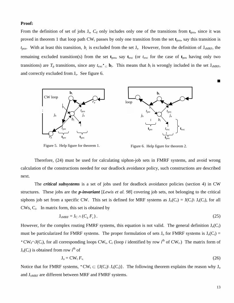
Theorem 3 (Critical subsystems sets in MRF and FMRF systems, importance of CWt) In a FMRF
system, the set of jobs JoMRF = JC ∧ ( is different from the set J)d FvC o = CWt Fv, only if there exists at least
one loop CWr containing one resource bi, which job bi has at least two precedent transitions tpre = , i.e. at
least two resources from the set r
ib•
ki-1 can perform jobs type ji-1, preceding job bi.
Proof:
Define the two resources from rki-1, as ra and rb, for ra, rb ⊂ { ( }. Then, from theorem 1, only one of the
transitions b
•• )ib
•i should be path of the loop CWt, say this resource is ra. This means that rb is not contained in
the CWr set. This results that the critical subsystems Jo = CWt Fv will contain only the job r••a∩ b••
i, since
( • ra∩ b•i)⊂(CWt) and JoMRF = JC ∧ contain wrongly both jobs r)( d FvC
••
ax and rby from resources ra and rb
since all b•i⊂(Cd
• ) and { rax ⊂ r••a, rby ⊂ rb} ∩ b•
i.
!
CW loop ra bi rax tpos
rki-1
bi rby rb tpre
Figure 7. Help figure for theorem 3.
That is why, for FMRF systems, i.e. systems having routing dispatching problems, it is so important to
calculate constructions CWt. Otherwise, if the standard definition set from MRF systems is used, one will
get wrong sets of critical subsystems.
Other important construction previously calculated is the union of simple circular waits, the CW set. The
next theorem defines and highlights one of important the considerations of such unions, other important
considerations will be described in the deadlock avoidance section.
Theorem 4 (Unions of CWs, importance of CWt) In FMRF systems, critical subsystems from a CW
might contain several jobs from a single set rki-1, only if the CW is a union of sCW which share at least one
resource buffer type bi (section 3) having at least two posterior transitions bi• .
14

Proof.
Consider the case buffer bi has at least two posterior transitions bi• , this means that at least two resources
type rki-1 exist. Define these two resources, as ra and rb, such that ra, rb ⊂ { ( }. Then, from theorem 1,
only one of the transitions b
•• )ib
i • should be path of each simple CW. This means that both resources cannot be
contained in a each simple CW. Assume two simple CWs, CW1 and CW2, such that resource ra is contained
in CW1, rb is contained in CW2, and that { r•a, • rb } ⊂ bi
• , i.e. transition { r•a∩bi
• }⊂ CWt1, and
{ r•b∩bi
• }⊂ CWt2, where CWt1 (CWt2) is the corresponding CWt matrix from CW1 (CW2).
Then, from the theorem assumption that bi is contained in the union of both CWs CW1, and CW2, this
means that {ra, rb, bi } ⊂ CWru, for CWru be the union of simple CWs CW1 and CW2. This results that the
correponding CWt matrix from CWru must contain union of both CWt1 and CWt2, from the corresponding
rows of (16) for CW1 and CW2. So that the general expression of critical subsystems Jo = CWt Fv, is
particularized for this set Jo(CWru)= [CWt1 ∧ CWt2]Fv, which will contain two jobs { rax ⊂ r••a, rby ⊂ r••
b} ⊂
rki-1.
CW loop ra bi rax tpos
rki-1
bi : rby rb tpre
Figure 8. Help figure for theorem 4.
!
4 Deadlock Avoidance
In terms of the constructions just given, we now present a minimally restrictive resource dispatching
policy that guarantees absence of deadlock for Free-Choice Multi-part Reentrant Flow-lines (FMRF). For
efficient implementation in real time of DE controllers, we use matrices for all computations. In this paper,
we are considering the case where the system is regular, that is, it cannot contain Critical Resources (CR)
(so-called structured bottleneck resources or ‘key resources’ [Xing 96, Gurel et al. 00] existing in Second
Level Deadlock (SLD) structures [Fanti et al. 97, 00].)
A mathematical regularity test for MRF systems is described in [Mireles et al. 02]. A forthcoming paper
will show the analysis of constructions for regularity test for FMRF systems. For the case the MRF/FMRF
system is not regular, we can still use this matrix formulation, but with a different dispatching policy
designed for irregular systems containing SLD structures, we will consider this casein a forthcoming paper.
15
4.1 Dispatching Policy
In this section we consider dispatching for regular systems. A matrix test for system-nonregularity is
given in the next section. In [Lewis et al. 98] was given a minimally restrictive dispatching policy for
regular systems that avoids deadlock for the class of MRF systems which has the first assumptions
considered on section 3 for FMRF systems, excluding the additional assumptions. That is, in MRF systems
all sets type rki defined for FMRF systems contain only one resource ri. So that it is not necessary the
presence of routing resources bi in MRF systems. In FMRF systems bi are not only resource buffers, but,
robotic systems that handle parts from several machines to other several machines, i.e. these act like
‘routers’ in communication systems. A brief note on deadlock, is that, for the class of MRF and FMRF
systems, deadlock is equivalent to a circular blocking (CB). There is a CB if and only if there is an empty
circular wait (CW) of resources. This always happens iff the corresponding critical siphon of that CW is
empty. By construction, in Lewis’ policy-structure terms, this is equivalent to all jobs of the CW being in
the associated Critical Subsystem (CS). Similarly, in terms of PN, there is a deadlock iff all tokens of the
CW are in the Critical Subsystem set.
Therefore, our first policy, key to deadlock avoidance, is to ensure that the WIP in the CS is limited
to one job less than the total number of initial tokens in the CW (i.e. the total number of resources available
in the CW). Due to the necessity and sufficiency of all the conditions just outlined, this MAXWIP policy
[Lewis et al. 98] is the least restrictive policy that guarantees absence of deadlock. It is very easy to
implement. Preliminary off-line computations using matrices are used to compute the CS. A supervisor is
assigned to each circular wait, and is responsible for dynamic dispatching by counting the jobs in the
corresponding CS and ensuring that they do not violate the following condition, for each CW Ci,
m(Jo(Ci)) < mo(Ci). (27)
That is, the number of enabled places contained in the CS for each Ci must not reach the total number of
resources contained in that Ci. However, for FMRF systems there exists a special case where all critical
subsystems are allowed to be full, i.e CW become empty without getting into a CB, or deadlock. Theorem 5
explains this special case.
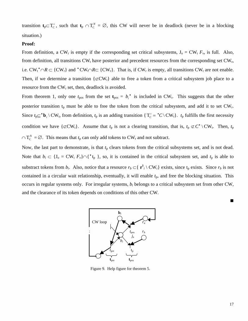
Theorem 5 (Acceptance of empty circular waits, special case on regular FMRF systems) For a FMRF
system having a simple CW containing at least one resource bi, which job bi has at least two posterior
transitions tpos = b , then, even if the CW is empty, and if any of those transitions t•i pos is an adding
16
transition tp⊂ , such that t+CT
\
p ∩ = ∅, this CW will never be in deadlock (never be in a blocking
situation.)
NCT
Proof:
From definition, a CWr is empty if the corresponding set critical subsystems, Jo = CWt Fv, is full. Also,
from definition, all transitions CWt have posterior and precedent resources from the corresponding set CWr,
i.e. CWt• ∩R ⊂ {CWr} and CW•
t∩R⊂ {CWr}. That is, if CWr is empty, all transitions CWt are not enable.
Then, if we determine a transition {⊄CWt} able to free a token from a critical subsystem job place to a
resource from the CWr set, then, deadlock is avoided.
From theorem 1, only one tpos from the set tpos = b is included in CW•i t. This suggests that the other
posterior transition tp must be able to free the token from the critical subsystem, and add it to set CWr.
Since tp⊆ • CWib t, from definition, tp is an adding transition { T CW\C C•+ = t}. tp fulfills the first necessity
condition we have {⊄CWt}. Assume that tp is not a clearing transition, that is, tp ⊄ CW\•C t. Then, tp
∩ T = ∅. This means that tNC p can only add tokens to CWr and not subtract.
Now, the last part to demonstrate, is that tp clears tokens from the critical subsystems set, and is not dead.
Note that bi ⊂ {Jo = CWt Fv}∩{ • tp }, so, it is contained in the critical subsystem set, and tp is able to
substract tokens from bi. Also, notice that a resource rb ⊂{ rki \ CWr} exists, since tp exists. Since rb is not
contained in a circular wait relationship, eventually, it will enable tp, and free the blocking situation. This
occurs in regular systems only. For irregular systems, bi belongs to a critical subsystem set from other CW,
and the clearance of its token depends on conditions of this other CW.
!
bi CW loop ra : tpos rb ja
bi tpre tp tpre tpos
Figure 9. Help figure for theorem 5.
17

For implementation purposes, for very DE iteration, a dispatching/decision policy must be selected.
Among all possible dispatching policies [Panwalkar et al. 77], one possible policy is the Least Slack (LS)
policy, which tries to optimize throughtput and minimize the variance of lateness of jobs waiting to be
processed [Kumar 93-94]. However, deadlock situations might appear in certain CWs while trying to
optimize throughtput. Therefore, we have to combine LS with our deadlock avoidance test (27). Thus,
before we intent to dispatch the LS resolution, we must examine the marking outcome with our deadlock
policy. If this resulting outcome does not satisfy (27), then the algorithm denies (pre-filters in real time)
firing the transition identified to deadlock the system. This is accomplished by adding an Fuc matrix, a
conflict resolution matrix, to our matrix based structure (see [Lewis et al. 98] for an example showing the
use of Fuc). Later, althought throughput might be comprimised, LS is run again for the next possible
allowable firing sequence without deadlock. Therefore, using optimal LS dispatching while permitted, we
will try to satisfy in most of the current status of the cell the case m(Jo(Ci)) = mo(Ci)-1, for efficiently
improve throughput.
5 Conclusion
An analysis for deadlock avoidance in Free-choice Multipart Reentrant Flow-lines (FMRF) is presented.
Definition of a general class of FMRF systems was provided. In FMRF systems shared resources are not
dedicated for certain jobs; some jobs have multiple resource choices in reentrant flow lines, i.e. routing
problems have to be solved. The development of deadlock-free dispatching rules was derived from circular
wait analysis for possible blocking situations. Analysis of constructions related to circular wait loops is
shown, including transition loops, resource loops, critical siphons, and certain critical subsystems. This
analysis was shown as an alalogy of Multipart Reentrant Flow-lines with no Free-choice routing dispatching
problems. The main supervisor is a Discrete Event (DE) controller which uses a Matrix-Based framework.
The Discrete Event Controller (DEC) guaranties deadlock avoidance by limiting the work-in-progress in the
critical subsystems associated with each CW. This is the least-restrictive dispatching policy that avoids
deadlock. We calculated in matrix form all constructions needed for implementation of DECs using online-
deadlock-free dispatching rules, for the case of FMRF systems being regular. Future research will cover
implementations of FMRF systems with routing dispatching problems, regularity tests for FMRF systems
and analysis of critical resources for the case of irregular systems having Second Level Deadlock structures.
18
References [1] Banaszak Z. A. and B. H. Krogh. “Deadlock Avoidance in Flexible Manufacturing Systems with Concurrently
Competing Process Flows.” IEEE Trans. Robotics and Automation, RA-6, pp. 724-734 (1990).
[2] Buzacott J.A. and D.D. Yao. “Flexible Manufacturing Systems: A Review of Analytical Models.” Management Sci. 7, pp. 890-905 (1986).
[3] Ezpeleta S. D., J. M. Colom and J. Martinez. “A Petri Net Based Deadlock Prevention Policy for Flexible Manufacturing Systems.” IEEE Trans. Robotics and Automation, RA-11, pp. 173-184 (1995).
[4] Fanti M.P., B. Maione, S. Mascolo, and B. Turchiano. “Event-Based Feedback Control for Deadlock Avoidance in Flexible Production Systems.” IEEE Transactions on Robotics and Automation, Vol. 13, No. 3, June 1997.
[5] Fanti M.P., B. Maione, S. Mascolo, and B. Turchiano. “Comparing Digraph and Petri Net Approaches to Deadlock Avoidance in FMS.” IEEE Transactions on Systems, Man, and Cybernetics-Part B: Cybernetics, Vol. 30, No. 5, October 2000.
[6] Graves S.C.. “A Review of Production Scheduling.” Operations Research, vol. 29, no. 4 (1981).
[7] Gurel A., S. Bogdan, and F.L. Lewis. “Matrix Approach to Deadlock-Free Dispatching in Multi-Class Finite Buffer Flowlines.” IEEE Transactions on Automatic Control. Vol. 45, no. 11, Nov. 2000, pp. 2086-2090.
[8] Harary F. “Graph Theory.” Addison-Wesley Pub. Co., Massachusetts 1972.
[9] Hsieh F.-S. and S.-C. Chang. “Dispatching-Driven Deadlock avoidance controller Synthesis for Flexible Manufacturing Systems.” IEEE Trans. Robotics and Automation, RA-11, pp. 196-209 (1994).
[10] Huang Hsiang-Hsi, F.L. Lewis, D. Tacconi. “Deadlock Analysis Using a New Matrix-Based Controller for Reentrant Flow Line Design.” Proceedings of the 1996 Industrial Electronics, Control, and Instrumentation. IEEE IECON 22nd International Conference on. Vol. 1. pp. 463 -468 vol.1 (1996).
[11] Hyuenbo C., T. K. Kumaran, and R. A. Wysk. “Graph-Theoretic Deadlock Detection and Resolution for Flexible Manufacturing Systems.” IEEE Transactions on Robotics and Automation, vol. 11, no. 3, pp. 413-421 (1995).
[12] Jeng M.D. and F. DiCesare. “Synthesis Using Resource Control Nets for Modeling Shared-Resource Systems.” IEEE Trans. Robotics and Automation, RA-11, pp. 317-327 (1995).
[13] Kumar, P.R. “Re-entrant lines.” Queueing Systems: Theory and Applications. Switzerland. vol. 13, pp. 87-110 (1993).
[14] Kumar, P.R. “Scheduling Semiconductor Manufacturing Plants.” IEEE Control Systems Magazine, Vol. 14, Issue 6, pp. 33-40. Dec. 1994.
[15] Kumaran, T. K., W. Chang, N. Cho and R. A. Wysk. “A Structured Approach to Deadlock detection, avoidance, and solution in Flexible Manufacturing Systems.” Int. Journal Prod. Res., vol. 32, pp. 2361-2379 (1994).
[16] Kusiak, A. and J. Ahn. “A Resource-Constrained Job Shop Scheduling Problem with General Precedence Constraints.” Working paper, no. 90-03, Iowa (1991).
[17] Kusiak A. and J. Ahn. “Intelligent Scheduling of Automated Machining Systems.” Computer Integrated Manufacturing Systems, vol.5, no.1, Feb. 1992, pp.3-14. UK (1992).
[18] Lewis, F.L., H.-H. Huang and S. Jagannathan. “A systems approach to discrete event controller design for manufacturing systems control.” Proceedings of the 1993 American Control Conference (IEEE Cat. No.93CH3225-0). American Autom. Control Council. pp.1525-31 vol.2. Evanston, IL, USA (1993 a).
[19] Lewis F.L., O.C. Pastravanu and H.-H. Huang. “Controller Design and Conflict Resolution for Discrete Event Manufacturing Systems.” Proceedings of the 32nd IEEE Conference on Decision and Control (Cat. No.93CH3307-6). IEEE. Part vol.4, pp.3288-93 vol.4. New York, NY, USA (1993 b).
[20] Lewis F.L. and H.-H. Huang. “Control System Design for Flexible Manufacturing Systems, in (A. Raouf and M. Ben Daya)” Flexible Manufacturing Systems: Recent Developments, Elsevier (1994 a).
[21] Lewis F.L., H.-H.Huang, O.C. Pastravanu, A. Gürel. “A Matrix Formulation for Design and Analysis of Discrete Event Manufacturing Systems with Shared Resources”. 1994 IEEE International Conference on Systems, Man, and Cybernetics. Humans, Information and Technology (Cat. No.94CH3571-5). IEEE. Part vol. 2, 1994, pp.1700-5. New York, NY, USA (1994 b).
19
[22] Lewis F.L., Gurel A, Bogdan S, Docanalp A, Pastravanu OC. “Analysis of Deadlock and Circular Waits using a Matrix Model for Flexible Manufacturing Systems.” Automatica, vol.34, no.9, Sept. 1998, pp.1083-100. Publisher: Elsevier, UK (1998).
[23] López-Mellado E. “Simulation of Timed Petri Net Models.” Systems, Man and Cybernetics, 1995. Intelligent Systems for the 21st Century., IEEE International Conference on , Volume: 3 , pp. 2270 –2273 (1995).
[24] Mireles, J. and F.L. Lewis, “On the Development and Implementation of a Matrix-Based Discrete Event Controller.” MED01, Proceedings of the 9th Mediterranean Conference on Control and Automation. Published on CD, reference MED01-012. June 27-29 2001. Dubrovnik, Croatia (2001a).
[25] Mireles, J. and F.L. Lewis. “Intelligent Material Handling: Development and Implementation of a Matrix-Based Discrete Event Controller.” IEEE Transactions on Industrial Electronics. Vol. 48, No. 6, December ‘01 (2001b).
[26] Mireles, J. and F.L. Lewis, A. Gurel. “Deadlock Avoidance for Manufacturing Multipart Reentrant Flow Lines Using a Matrix-Based Discrete Event Controller.” Int. Journal of Production Research. To appear (2002).
[27] Murata, T. (1989). “Petri Nets: Properties, Analysis and Applications.” Proceedings of the IEEE, vol.77, no.4, April 1989, pp.541-80. USA.
[28] Panwalkar S.S. and W. Iskander. “A Survey Of Scheduling Rules,” Operations Research, vol. 26, pp. 45-61 (1977).
[29] Pastravanu O.C., A. Gürel, F. L. Lewis and H.-H. Huang. “Rule-Based Controller Design Algorithm For Discrete Event Manufacturing Systems.” Proceedings of the 1994 American Control Conference (Cat. No.94CH3390-2). IEEE. Part vol.1, pp.299-305 vol.1. New York, NY, USA (1994 a).
[30] Pastravanu, O. C., A. Gürel and F. L. Lewis. “Petri Net Based Deadlock Analysis in Flowshops with Kanban-Type Controllers.” 10th ISPE/IFAC International Conference on CAD/CAM, Robotics and Factories of the Future CARs & FOF `94. Information Technology for Modern Manufacturing. Conference Proceedings. OCRI Publications. pp.75-80. Kanata, Ont., Canada (1994 b).
[31] Peterson J.L. “Petri Net Theory and the Modeling of Systems.” Prentice-Hall. 1981, Englewood Cliffs, NJ, USA (1981).
[32] Spearman M.L., D.L Woodruff, and W. Hopp “CONWIP: a pull alternative to kanban.” Int. J. Prod. Res., Vol. 28, No. 5, 1990, pp. 879-894 (1990).
[33] Spearman, M.L., D.L. Woodruff, and W.J. Hopp, “CONWIP: a Pull Alternative to Kanban.” Int. J. Production Research, vol. 28, no. 5, pp. 879-894 (1990).
[34] Tacconi D.A. and Lewis F.L. “A New Matrix Model for Discrete Event Systems: Application to Simulation.” IEEE Control Systems (1997).
[35] Wysk, R. A., N. S. Yang and S. Joshi. “Detection of Deadlocks in Flexible Manufacturing Cells.” IEEE Trans. Robotics Automet., RA-7, 853-859 (1991).
[36] Xing K. Y., B.S. Hu, and H.X. Chen. “Deadlock Avoidance Policy for Petri-Net Modeling of Flexible Manufacturing Systems with Shared Resources.” Automatic Control, IEEE Transactions on , vol. 41 issue 2 , Pp. 289-295. Feb. 1996.
[37] Zhou, M., F. DiCesare and A. A. Desrochers. “A Hybrid Methodology for Synthesis of Petri Net Models for Manufacturing Systems.” IEEE Trans. Robotics and Automation, vol. 8, no. 3, pp. 350-361 (1992).
[38] Zhou M., F. DiCesare. “Petri Nets Synthesis for Discrete Event Control of Manufacturing Systems”, Kluwer Academic Publishers (1993).
20