rules for building and classing steel vessels...part 9-f chapter 1 irs rules for building and...
TRANSCRIPT

IRS
RULES FOR BUILDING AND CLASSING STEEL VESSELS PART 9 : VESSELS FOR TRADE IN INLAND WATERWAYS
F : ADDITIONAL REQUIREMENTS FOR NOTATIONS
DECEMBER 2013
INTERNATIONAL REGISTER OF SHIPPING
Technical Appraisal Department 4770 Biscayne Boulevard
Suite 800 Miami, Florida 33137, USA


PART 9 – F IRS Rules for Building and Classing Steel Vessels
INTERNATIONAL REGISTER OF SHIPPING 3
CHANGES
PART 9-F IRS Rules for Building and Classing Steel Vessels
4 INTERNATIONAL REGISTER OF SHIPPING
CONTENTS
CHAPTER 1 TYPE AND SERVICE NOTATIONS ....................................................................... 5
SECTION 1 CARGO VESSELS ............................................................................................................. 6
SECTION 2 DOUBLE HULL CARGO VESSELS ................................................................................. 13
SECTION 3 TANKER ........................................................................................................................... 20
SECTION 4 CONTAINER VESSELS ................................................................................................... 37
SECTION 5 RORO VESSELS ............................................................................................................. 43
SECTION 6 PASSENGER VESSELS .................................................................................................. 52
SECTION 7 TUGS AND PUSHERS..................................................................................................... 76
SECTION 8 PONTOONS ..................................................................................................................... 79
SECTION 9 VESSELS FOR DREDGING ACTIVITIES ....................................................................... 82
SECTION 10 LAUNCHES .................................................................................................................... 86
CHAPTER 2 ADDITIONAL CLASS NOTATIONS ...................................................................... 89
SECTION 1 TRANSPORT OF HEAVY CARGOES ............................................................................. 90
SECTION 2 EQUIPPED FOR TRANSPORT OFCONTAINERS ......................................................... 93
SECTION 3 EQUIPPED FOR TRANSPORT OF WHEELED VEHICLES ......................................... 101
SECTION 4 FERRY ........................................................................................................................... 103
SECTION 5 STABILITY ...................................................................................................................... 106
SECTION 6 FIRE ............................................................................................................................... 125
SECTION 7 UNATTENDED MACHINERYSPACES (AUT-UMS) ...................................................... 131
SECTION 8 GRABLOADING ............................................................................................................. 140
SECTION 9 POLLUTION PREVENTION (CLEAN VESSEL) ............................................................ 142
CHAPTER 3 TRANSPORT OF DANGEROUS GOODS ...........................................................170
SECTION 1 GENERAL ...................................................................................................................... 171
SECTION 2 TYPE G .......................................................................................................................... 186
SECTION 3 TYPE C ........................................................................................................................... 212
SECTION 4 TYPE N ........................................................................................................................... 238
SECTION 5 OIL SEPARATOR VESSEL ........................................................................................... 264
SECTION 6 SUPPLY VESSEL .......................................................................................................... 282
SECTION 7 DG .................................................................................................................................. 300
SECTION 8 DGL ................................................................................................................................ 310
SECTION 9 DGD ................................................................................................................................ 316
PART 9 – F IRS Rules for Building and Classing Steel Vessels CHAPTER 1
INTERNATIONAL REGISTER OF SHIPPING 5
CHAPTER 1 TYPE AND SERVICE NOTATIONS
CONTENTS
SECTION 1 CARGO VESSELS ................................................................................................ 6
SECTION 2 DOUBLE HULL CARGO VESSELS ................................................................................. 13
SECTION 3 TANKER ........................................................................................................................... 20
SECTION 4 CONTAINER VESSELS ................................................................................................... 37
SECTION 5 RORO VESSELS .............................................................................................................. 43
SECTION 6 PASSENGER VESSELS .................................................................................................. 52
SECTION 7 TUGS AND PUSHERS ..................................................................................................... 76
SECTION 8 PONTOONS ..................................................................................................................... 79
SECTION 9 VESSELS FOR DREDGING ACTIVITIES ........................................................................ 82
SECTION 10 LAUNCHES .................................................................................................................... 86
PART 9-F CHAPTER 1 IRS Rules for Building and Classing Steel Vessels
6 INTERNATIONAL REGISTER OF SHIPPING
SECTION 1 CARGO VESSELS Contents
1.1. Symbols .............................................................................................................................................. 7
1.2. General ............................................................................................................................................... 7
1.3. Vessel arrangement ........................................................................................................................... 7
1.4. Structure design principles ................................................................................................................. 8
1.5. Hull scantlings .................................................................................................................................. 10

PART 9 – F IRS Rules for Building and Classing Steel Vessels CHAPTER 1
INTERNATIONAL REGISTER OF SHIPPING 7
1.1. Symbols
L = Rule length [m] defined in Part 9C Chapter 1, Section 1, [1.2.1]; B = Breadth, in [m] defined in Part 9C Chapter 1, Section 1, [1.2.1]; D = Depth [m] defined in Part 9C Chapter 1, Section 1, [1.2.1]; T = Draught [m] defined in Part 9C Chapter 1, Section 1, [1.2.1]; t = Net thickness [mm] of plating; Ash = Net web sectional area [cm2]; Z = Net section modulus [cm3] of ordinary stiffeners or primary supporting members; S, s = Stiffener spacing [m]; ℓ = Stiffener span [m]; k = Material factor defined in Part B Chapter 2 Section 6; βb, βS = Bracket coefficients defined in *****, n = Navigation coefficient defined in Part 1.
= 0.8 ⋅ 𝐻 , 𝐻 ≥ 2
= 1.0 , 𝐻 < 2 H = Significant wave height [m].
1.2. General
1.2.1. Application 1.2.1.1. Vessels which meet the requirements of this Section qualify for the assignment of
the type and service Notation Cargo vessel, as defined in Part 9A, Chapter 2 Section 2, [2.3.1.1]
1.2.1.2. Vessels dealt herein this Section are required to meet the requirements given in Part A, Part B Part C Part D & Part E of IRS Rules for Inland Navigation Vessels, as applicable, and also with the requirements laid out in this Section, which are specific to single hull cargo vessels.
1.2.2. Stability
Proof of adequate stability is required by IRS on the basis of vessel’s design and operating conditions.
1.3. Vessel arrangement
1.3.1. General 1.3.1.1. Application
The requirements of this Section are applicable to open deck vessels of single side construction, which may or may not have double bottom. Such vessels are primarily involved in carrying uniform or bulk dry cargoes and loading/unloading may be performed in one or two runs on them.
1.3.2. Protection of cargo holds 1.3.2.1. Coating
Following the Part 9 C, Chapter 2, Section 6, [6.2], the metallic structures are to be protected against corrosion. For the same purpose, it is required that suitable coatings are chosen for the intended cargoes (which are particularly compatible with the cargo) and applied as per manufacturer’s recommendations.
PART 9-F CHAPTER 1 IRS Rules for Building and Classing Steel Vessels
8 INTERNATIONAL REGISTER OF SHIPPING
1.3.2.2. Cargo hold ceiling Depending on the nature of cargo, it is required that a suitable metallic or wooden ceiling is used to sheath the cargo hold bottom to the upper part of bilges. Where a side ceiling is provided, secured after 4 frame spacings, by an effective system.
1.3.3. Accesses 1.3.3.1. Access to double bottom
For easy access to all the parts of double bottom, manholes may be cut in the floors and side girders and these are to be cut smooth along a well-rounded design. Moreover, these are not to be greater than that necessary to provide the human access. Where manholes of greater sizes are required, edge reinforcement by means of flat bar rings or other stiffeners may be used with prior approval of the Society. As a Rule, the manholes height is not to exceed 0.6 times the floor height or girder height. In the floors, manholes are to be located at half the floor height and in a region
extending on 0.2⋅B from the axis of the vessel, on both sides. Where a girder exits, its distance to the nearest side of cutting is not to be less than the double bottom height The location of manholes in the side girders is to be at half the girder height and in the middle of two successive web frames.
1.3.3.2. Access to cargo hold If feasible, for survey and maintenance of the cargo holds properly, permanent or removable means of access on board are to be provided.
1.4. Structure design principles
1.4.1. Bottom structure 1.4.1.1. To comply with the requirements of Part 9 C Chapter 5 Section 1, 1.4 & 1.5, single
bottom vessels shall be fitted with girders.
1.4.1.2. Transversely framed single bottom At every frame, a transversely framed single bottom shall be fitted with floors.
1.4.1.3. Longitudinally framed single bottom Generally, longitudinal stiffeners are to be continuous when crossing primary members. If longitudinals are located in way of the web frames of transverse bulkheads, its section modulus is to be increased by 10 %. Longitudinals are not to be supported by transverses whose spacing is to be not greater than 8 frame spacing, nor more than 4 m, which is the lesser.
1.4.2. Double bottom structure 1.4.2.1. Double bottom arrangement

PART 9 – F IRS Rules for Building and Classing Steel Vessels CHAPTER 1
INTERNATIONAL REGISTER OF SHIPPING 9
Inaccessible spaces of the double bottoms should be adequately protected against corrosion. Where there is variation in the height of the double bottom, it is to be gradually tapered over adequate length; the knuckles of inner bottom plating are to be located in the path of plate floors. Where it is not feasible on longitudinal structures, suitable longitudinal brackets, partial girders, etc., are to be fitted across the knuckle.
1.4.2.2. All double bottom vessels are to have a centre girder. However, it is not required where the breadth of the vessel measured on the top of floors or bottom transverses does not exceed 6 m. The intercostal centre girder is to extend over vessel’s full length or over the greatest length consistent with the lines.
1.4.2.3. Transversely framed double bottom It is required to fit the floors at every frame wherever the double bottom is transversely framed. It is required to fit watertight floors:
In the pathway of double bottom steps;
In the pathway of transverse watertight bulkheads.
1.4.2.4. Longitudinally framed double bottom The spacing of transverses [m] is not to be greater than 8 frame spacing or 4 m, whichever is less. Additional transverses are to be fitted in way of transverse watertight bulkheads. Inner and bottom longitudinal ordinary stiffeners are to be continuous through the transverses. In case, longitudinals are interrupted in way of a transverse, brackets on both sides of the transverse are to be fitted in perfect alignment. In general, intermediate brackets are to be fitted connecting the centre girder to the nearest inner bottom and bottom ordinary stiffeners.
1.4.3. Transversely framed side 1.4.3.1. Connection of frames with floors
The frames are to be connected to the floors, generally using lap weld the length of which is not to be less than:
1.5 times the frame depth, in case of frames made of a bulb profile or toe welded angle;
The frame depth, in case of frames made of a welded flat.
The weld throat is not to be less than half the frame web thickness.
1.4.3.2. Connection with deck structure
PART 9-F CHAPTER 1 IRS Rules for Building and Classing Steel Vessels
10 INTERNATIONAL REGISTER OF SHIPPING
At the upper end of frames, connecting brackets are to be provided, as given in Part 9C Chapter 5, Section 1, [1.4.3]. These brackets are to extend to the hatch coaming.
1.4.3.3. Web frames Web frames are to be fitted with not more than 5 [m] spacing. Their scantling is to be performed as per [1.5.2.2] below.
1.4.3.4. Connection of frames to bottom longitudinals In longitudinally stiffened single bottom, the side frames are connected to the bottom longitudinal at side, either directly or via a bracket. At the upper part of frame, there are connecting brackets, extending up to the deck longitudinal at side and even to:
The hatch coaming, in general;
The side trunk bulkhead, in a wing tank vessel.
1.4.4. Longitudinally framed side 1.4.4.1. Side transverses
The spacing between side transverses [m] is not to be greater than 8 frame spacing or 4 m, whichever is less. Their scantling is to be performed as per 1.5.2.2 below. The side transverses are directly welded to the shell plating but in double bottoms, these are to be bracketed to the bottom transverses.
1.4.4.2. Side longitudinals Longitudinal ordinary stiffeners are to be continuous when crossing primary supporting members. If longitudinals are interrupted by a primary supporting member, brackets on both sides are to be fitted in perfect alignment.
1.4.5. Topside structure 1.4.5.1. Strength continuity
At ends of the cargo hold space, the members contributing to the overall strength are to be correctly staggered. Such arrangements are to be made which ascertain strength continuity of the topside structure at the end of the hatchways. As much as feasible, it is recommended that the part of the hatch coaming which is located above deck is extended to connect it to the side bulkheads of the accommodation spaces.
1.5. Hull scantlings
1.5.1. General The hull scantlings are to be in compliance with Part 9 C Chapter 5, unless specified otherwise.

PART 9 – F IRS Rules for Building and Classing Steel Vessels CHAPTER 1
INTERNATIONAL REGISTER OF SHIPPING 11
1.5.2. Transverse rings 1.5.2.1. General
Where it is essential, transverse rings are to be fitted so as to render additional support to the stringer plate.
1.5.2.2. Scantlings of transverse ring components The ring component scantlings are not to be less than that required as per Table 1.1.1
1.5.3. Transverse hold bulkhead structure 1.5.3.1. General
Part 9C Chapter 3, Section 1, [1.3] defines the number and location of transverse bulkheads. Where it is essential, additional bulkheads are to be fitted so as to render adequate transverse strength to the vessel. The scantlings of transverse hold bulkheads are not to be less than as required in Part 9 C, Chapter 5 Section 4.
Table 1.1.1: Net scantlings of transverse rings
Primary supporting member Z Ash
Side webs Floors
𝑧 = 𝑘𝑀𝐴𝑋(𝑤1 , 𝑤2)
𝑧1 = 1.96. 𝛽𝑏 ∙ 𝑘0 ∙ 𝑝. 𝑆. ℓ02
𝑧2 = 0.58 ∙ 𝛽𝑏 ∙ 𝑝𝛾𝐸 ∙ 𝑠. 𝐵2
𝑤1 = 1.96. 𝛽𝑏 ∙ 𝑘0 ∙ 𝑝. 𝑆. ℓ02
w1 =
1, 96 ⋅ βb ⋅ k0 ⋅ p ⋅S ⋅ A 0 w2 = 0,58
𝐴𝑠ℎ = 𝑘 𝑀𝐴𝑋(𝐴1, 𝐴2)
𝐴1 = 0.063. 𝛽𝑠 ∙ 𝑘0 ∙ 𝑝 ∙ 𝑆 ∙ ℓ0 𝐴2 = 0.045 ∙ 𝛽𝑠 ∙ 𝑝𝛾𝐸 . 𝑠. 𝐵
Side transverses Bottom transverses Bottom
𝑧 = 𝑘𝑀𝐴𝑋(𝑧1, 𝑧2)
𝑧1 = 1.96. 𝛽𝑏 ∙ 𝑘0 ∙ 𝑝. 𝑆. ℓ02
𝑧2 = 0.58 ∙ 𝛽𝑏 ∙ 𝑝𝛾𝐸 ∙ 𝑠. 𝐵2
w2 = 0,58⋅βb⋅pγE⋅S⋅B2
𝐴𝑠ℎ = 𝑘 𝑀𝐴𝑋(𝐴1, 𝐴2)
𝐴1 = 0.063. 𝛽𝑠 ∙ 𝑘0 ∙ 𝑝 ∙ 𝑆 ∙ ℓ0 𝐴2 = 0.045 ∙ 𝛽𝑠 ∙ 𝑝𝛾𝐸 . 𝑠. 𝐵
P = side primary supporting members design load [kN/m2] = 4.9 ⋅ (𝑇 + 0.6 ⋅ 𝑛) pγE = bottom primary supporting members design load [kN/m2] = 9.81 ⋅ ( ⋅ 𝑇 + 0.6 ⋅ 𝑛)
= 1.0 for loading/unloading in one run = 0.575 for loading/unloading in two runs ℓ0 = 𝑇 + 0.6 ⋅ 𝑛
𝑘0 = 1 + (𝐷 − ℓ0) / ℓ0
1.5.3.2. Vertically framed plate bulkhead
The upper end of the vertical stiffeners is to be connected either to a stringer located at the stringer plate level or above or strong deck box beam.

PART 9-F CHAPTER 1 IRS Rules for Building and Classing Steel Vessels
12 INTERNATIONAL REGISTER OF SHIPPING
As much as feasible, the bottom of the box beam or the bulkhead end stringer is to be located in the same plane as the stringer plate. If it is not possible, bulkhead plating or the box beam sides are to be fitted with efficient horizontal framing at that level.
1.5.3.3. Horizontally framed plate bulkhead IRS shall specially consider the upper part of horizontally framed bulkheads.
1.5.3.4. Plate bulkhead end stringer Following formula is used to determine the net scantlings of the plate bulkhead end stringer:
𝑧 = 125. 𝑘
214 − 𝐴
𝑝. 𝑆. ℓ2
P = bulkhead end stringer design load [kN/m2] to be determined using applicable formulas given in Part 9C Chapter 5 Section 4, [4.3.1].
S = bulkhead stringer spacing [m]; σA= bulkhead end stringer axial stress [N/mm2];
= 10.q.D1
A
A = bulkhead end stringer sectional area [cm2] to be determined in compliance with Part 9 C, where:
𝑃𝑆 = 𝑞. 𝐷1 q = Distributed transverse load acting on the stringer plate [kN/m]. D1 = unsupported stringer plate length [m].
In way of hold end bulkheads D1 is to be substituted by 0.5 ⋅ D1.
PART 9 – F IRS Rules for Building and Classing Steel Vessels CHAPTER 1
INTERNATIONAL REGISTER OF SHIPPING 13
SECTION 2 DOUBLE HULL CARGO VESSELS Contents
2.1. Symbols ............................................................................................................................................ 14
2.2. General ............................................................................................................................................. 14
2.3. Vessel arrangement ......................................................................................................................... 14
2.4. Structure design principles ............................................................................................................... 15
2.5. Hull scantlings................................................................................................................................... 18

PART 9-F CHAPTER 1 IRS Rules for Building and Classing Steel Vessels
14 INTERNATIONAL REGISTER OF SHIPPING
2.1. Symbols
L = Rule length [m] defined in Part 9C Chapter 1, Section 1, [1.2.1];. B = Breadth [m] defined in Part 9C Chapter 1, Section 1, [1.2.1];. D = Depth [m] defined in Part 9C Chapter 1, Section 1, [1.2.1]; T = Draught [m]; t = Net thickness [mm] of plating.
2.2. General
2.2.1. Application Vessels which meet the requirements of this Section qualify for the assignment of the type and service notation Cargo vessel, as specified in Part 9 A Chapter 2 Section 2, [2.3.1.1]. Vessels dealt herein the following are to conform to the requirements stipulated in Part A,B,C,D & E Rules for Inland Navigation Vessels, as applicable, and also with the requirements, which are specific to double hull cargo vessels.
2.2.2. Stability Proof of adequate stability is required by IRS on the basis of vessel’s design and operating conditions.
2.3. Vessel arrangement
2.3.1. General 2.3.1.1. Application
The requirements of this Section are applicable to open deck vessels of double hull construction, primarily involved in carrying uniform or bulk dry cargoes and loading/unloading may be performed in one or two runs on them.
2.3.2. Protection of cargo holds
2.3.2.1. Coating Following the Part 9 C Chapter 2 Section 6, [6.2], metallic structures are to be protected against corrosion. For the same purpose, it is required that suitable coatings are chosen for the intended cargoes (which are particularly compatible with the cargo) and applied as per manufacturer’s recommendations.
2.3.3. Accesses 2.3.3.1. Access to double bottom
For easy accessibility to all the parts of double bottom, manholes may be cut in the floors and side girders and these are to be cut smooth along a well-rounded design. Moreover, these are not to be greater than that necessary to provide the human access. Where manholes of greater sizes are required, edge reinforcement by means of flat bar rings or other stiffeners may be used. As a Rule, the manholes height is not to exceed 0.6 times the floor height or girder height.

PART 9 – F IRS Rules for Building and Classing Steel Vessels CHAPTER 1
INTERNATIONAL REGISTER OF SHIPPING 15
In the floors, manholes are to be located at half the floor height and in a region extending on 0.2⋅B from the axis of the vessel, on both sides. Where a girder exits, its distance to the nearest side of cutting is not to be less than the double bottom height. Manholes in the side girders are to be located at half the girder height and in the middle of two successive web frames. If there is no web frame, their distance from the transverse bulkheads of the side tanks is not to be less than 1.5 m. IRS may consider deviation from this rule subject to direct calculation of the shear stresses.
2.3.3.2. Access to side tanks Where openings that allow access to side tanks are cut in the stringer plate, they are to be clear of the hatch corners and shall be of even-deck design, without obstacles causing stumbling. To ascertain strength continuity, manholes are to be cut smooth along a well-rounded design and strengthened by thick plates, doubling plates or other equivalent structure.
2.3.3.3. Access to cargo hold If feasible, for survey and maintain the cargo holds properly, permanent or removable means of access are to be provided on board are.
2.3.4. Welding 2.3.4.1. General
Welding is to be done in compliance with the Part 9C Chapter 2 Section 7.
2.3.4.2. Arrangements applying to the shell plating and the double bottom Transverse welds are to be butt welded. Double bottom butts may be welded in way of floor faceplate which acts as a support. The longitudinal joints are to be attained either by butt welding or by overlap welding. In the second case, the outer line welding is to be continuous with a throat
thickness of 0.5⋅t, whereas the inner line of welding may be discontinuous with a
ratio p/d < 4 and a throat thickness of 0.5⋅t; however, for spaces which are not accessible after construction, the inner weld is to be done with a continuous line welding.
2.3.4.3. Arrangements applying to the topside plating Butt weldings are to be done on the transverse connections of the sheerstrake, stringer plate and coaming.
2.4. Structure design principles
2.4.1. Double bottom structure
2.4.1.1. Double bottom arrangement Where possibility of visiting double bottoms is not likely, they are to be adequately protected against corrosion.
PART 9-F CHAPTER 1 IRS Rules for Building and Classing Steel Vessels
16 INTERNATIONAL REGISTER OF SHIPPING
Where there is variation in height of the double bottom, this is generally to be tapered gradually and over an adequate length; the knuckles of inner bottom plating are to be located in way of plate floors. Where this is not possible on longitudinal structures, appropriate longitudinal brackets, partial girders, etc., are to be fitted across the knuckle.
2.4.1.2. Girders On all the vessels exceeding breadth of 6m, a centre girder is to be fitted which is formed by a vertical intercostal plate connected to the bottom plating and fitted with a faceplate. The intercostal centre girder, having same thickness as floors, is to extend over the full length of the vessel or over the greatest length consistent with the lines. No manholes are provided into the centre girder. On vessels with ranges of R0, R100, continuous or intercostal girders are to be fitted in the extension of the inner sides. These shall have a net thickness equal to that of the inner sides. On vessels with ranges of R0, R100 built in the transverse system and without web frames, partial intercostal girders are to be fitted in way of the transverse bulkheads of the side tanks. These girders are to be extended at each end by brackets having length equal to 1 frame spacing. They are to have a net thickness equal to that of the inner sides.
2.4.1.3. Transversely framed double bottom In case of transversely framed double bottom, floors are to be fitted at every frame. Watertight floors are to be fitted:
In way of transverse watertight bulkheads;
In way of double bottom steps.
2.4.1.4. Longitudinally framed double bottom The spacing of transverses is not to be greater than 8 frame spacing or 4 m, whichever is the less.
Additional transverses are to be fitted in the way of transverse watertight bulkheads. Bottom and inner bottom longitudinal ordinary stiffeners are to be continuous through the transverses. Where longitudinals are interrupted in way of a transverse, brackets on both sides of the transverse are to be fitted in perfect alignment. In general, intermediate brackets are to be fitted connecting the centre girder to the nearest bottom and inner bottom ordinary stiffeners.
2.4.1.5. Strength continuity Brackets shall be used to give adequate strength continuity of floors and bottom transverses in way of the side tank.
2.4.2. Transversely framed double side
PART 9 – F IRS Rules for Building and Classing Steel Vessels CHAPTER 1
INTERNATIONAL REGISTER OF SHIPPING 17
2.4.2.1. Structural arrangement
Where the inner side does not extend up to the outer bottom, it is to be held in position by brackets or vertical stiffeners fitted to the floors. Adequate continuity strength is to be ascertained in way of changes in width of the double side. Scarring of the inner side is to be ensured beyond the cargo hold region.
2.4.2.2. Side and inner side frames At their side, inner side and upper end, frames are to be connected using a bracket, which can be a section or a flanged plate with a section modulus at least equal to that of the side web frames. Where the outer and inner side frames are connected via struts located at mid-span, their section modulus may be reduced by 30%. The strut sectional area is not to be less than those of the connected frames. At their lower end, frames are to be connected to the floors or top tank.
2.4.2.3. Side and inner side web frames It is recommended that side web frames are provided and fitted every 3 m and not more than 6 frame spacings apart. At their side, inner side and upper end, web frames are to be connected by a bracket which can be a section or a flanged plate with a section modulus at least equal to that of the side web frames. An attached plate strip may be taken into account. The web frames are to be connected at their mid-span by struts, the cross-sectional area of which is not to be less than the connected web frames. At their lower end, the web frames are to be connected to the floors or tanktop.
2.4.2.4. Plate webs Plate webs may be fitted either in addition or in the place of web frames. Plate webs are to be fitted with horizontal stiffeners whose spacing is not to be greater than 1 m. IRS examines the scantling of web plates with large openings on a case-by-case basis.
2.4.3. Longitudinally framed double side 2.4.3.1. Inner side plating
The requirements of 2.4.2.1 are also applicable to longitudinally framed double side, with the transverses instead of web frames.
2.4.3.2. Side and inner side longitudinals Where the outer and inner side longitudinals are connected via struts located at mid-span, their section modulus may be reduced by 30%.
PART 9-F CHAPTER 1 IRS Rules for Building and Classing Steel Vessels
18 INTERNATIONAL REGISTER OF SHIPPING
The strut sectional area is not to be less than that of the connected longitudinals.
2.4.3.3. Side transverses The requirements of 2.4.2.3 are also applicable to longitudinally framed double side, with the transverses instead of web frames.
2.4.3.4. Plate webs The requirements of 2.4.2.4 are also applicable to longitudinally framed double side.
2.4.4. End structure 2.4.4.1. Arrangements for self-propelled vessels
At ends of the cargo hold space, the strength continuity of members contributing to the overall strength is to be provided adequately. Arrangements are to be made to ascertain strength continuity of the top structure at the end of the hatchways, in particular. If feasible, it is recommended that part of the hatch coaming which is located above deck is extended and connected to the side bulkheads of the accommodation spaces. The longitudinal boundaries of the engine room side bunkers are to be located, as much as feasible, in the extension of the double hull sides.
2.4.4.2. Arrangements for pushed vessels Where small size compartments exist outside the cargo hold space, the strength continuity is to be ascertained by scarring of strength members. The double hull sides are to be extended outside the cargo hold space, in the shape of brackets, over a distance equal to two times the stringer plate width. Strength continuity of the inner bottom is to be ascertained with help of brackets, one of which is to be along the vessel’s centreline. Where the vessel ends are made on the longitudinal system, brackets are to be connected to the bottom longitudinals; or otherwise to keelsons.
2.5. Hull scantlings
2.5.1. General As per Part 9 C Chapter 5 the hull scantlings and arrangements are to be determined, unless otherwise specified.
2.5.2. Double bottom structure 2.5.2.1. General arrangements
Where inner side plating does not extend to the bottom plating, floors of vessels made in the transverse system are to be stiffened, at each frame, in path of the double hull shell plating, using a section, the net sectional area of which [cm2] is not to be less than as computed below:
𝐴 = 0.01. 𝑏. 𝑡𝐹
PART 9 – F IRS Rules for Building and Classing Steel Vessels CHAPTER 1
INTERNATIONAL REGISTER OF SHIPPING 19
tF = Net thickness of floor web [mm]; b = Section height [mm];
= 100 ⋅ HD HD = Double bottom height [m]; Where floors cannot be welded to the inner bottom with help of fillet welds, the attachment may be done using plug welds, in compliance with Chapter 2 Section 7 In that case, floors are to be fitted with an adequately sized flange in the double bottom area. As a Rule, no manholes are to be provided in the centreline girder.
2.5.3. Transverse hold bulkhead structure The arrangements and scantlings of transverse hold bulkheads are to be conformation to Part 9 C Chapter 5 Section 4.

PART 9-F CHAPTER 1 IRS Rules for Building and Classing Steel Vessels
20 INTERNATIONAL REGISTER OF SHIPPING
SECTION 3 TANKER
Contents
3.1. Symbols ............................................................................................................................................ 21
3.2. Application ........................................................................................................................................ 21
3.3. Vessel arrangement ......................................................................................................................... 21
3.4. Hull scantlings .................................................................................................................................. 24
3.5. Transverse rings............................................................................................................................... 32
3.6. Structural arrangements ................................................................................................................... 33
3.7. Subdivision ....................................................................................................................................... 35

PART 9 – F IRS Rules for Building and Classing Steel Vessels CHAPTER 1
INTERNATIONAL REGISTER OF SHIPPING 21
3.1. Symbols
L = Rule length [m] defined in Part 9C Chapter 1, Section 1, [1.2.1]. B = Breadth [m] defined in Part 9C Chapter 1, Section 1, [1.2.1]. D = Depth [m] defined in Part 9C Chapter 1, Section 1, [1.2.1]. T = Draught [m] defined in Part 9C Chapter 1, Section 1, [1.2.1]. B2 = Side tank breadth [m];
𝐵1 = 𝐵 − 2 ⋅ 𝐵2 t = Net thickness [mm] of plating; p = Design load [kN/m2]; pPV = Setting pressure [kN/m2] of safety valves or maximum pressure [kN/m2] in the tank during
loading/unloading, which is the greater; s = Spacing of ordinary stiffeners [m]; S = Spacing of primary supporting members [m]; ℓ = Span [m]; w = Net section modulus [cm3]; Ash = Net web sectional area [cm2]; k = Material factor defined in Part 9C Chapter 2 Section 2,[ 2.3] z = Z co-ordinate [m] of the calculation point; zTOP = Z co-ordinate [m] of the highest point of the tank; dAP = Distance from the top of air pipe to the top of compartment [m]; HT = Trunk height [m]; zL = Z co-ordinate [m] of the highest point of the liquid; ρL = Density [t/m3] of the liquid carried ≥1 t/m3; σ1 = In-plane hull girder normal stress [N/mm2]; λb, λs = Coefficients for vertical structural members, βb, βs = Bracket coefficients n = Navigation coefficient defined in Part 1.
= 0.85 ⋅ 𝐻 H = Significant wave height [m];
𝜂 = 1 − 𝑠 / (2 ⋅ ℓ ) 3.2. Application
3.2.1. General 3.2.1.1. Vessels which meet the requirements given here qualify for the assignment of
the type and service Notation Tanker, as defined Part 9 A Chapter 2 Section 2 , [2.4.1.1.].
3.2.1.2. Vessels dealt herein this Section are in compliance with the requirements given in
Part 9 A, B, C,D, E as applicable, and with the requirements of this Section, which are specific to tankers.
3.3. Vessel arrangement
3.3.1. Basic structural configuration 3.3.1.1. Single hull tankers
In single hull tanker, see Fig. 1.3.1, cargo tanks are bounded by the vessel’s outer shell, i.e. the sides of the shell plating, the bottom and the decks and all of them together act as tank walls.
3.3.1.2. Double hull tankers As per [3.3.1.1], in single hull tanker, cargo tanks form part of vessel's structure. However, if one see Fig. 1.3.2., it is seen that the bottom and side plating does not

PART 9-F CHAPTER 1 IRS Rules for Building and Classing Steel Vessels
22 INTERNATIONAL REGISTER OF SHIPPING
simultaneously function as tank walls. For certain products, minimum distances between bottom or side plating and tank boundaries are to be observed. Moreover, accessibility shall be guaranteed in every case.
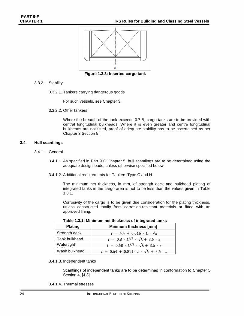
3.3.1.3. Tankers with inserted cargo tanks In such type of vessels, cargo tanks are independent of the vessel's structure but are permanently installed, see Fig. 1.3.3.
Figure 1.3.1: Single hull tankers

PART 9 – F IRS Rules for Building and Classing Steel Vessels CHAPTER 1
INTERNATIONAL REGISTER OF SHIPPING 23
Figure 1.3.2 Double hull tankers
PART 9-F CHAPTER 1 IRS Rules for Building and Classing Steel Vessels
24 INTERNATIONAL REGISTER OF SHIPPING
Figure 1.3.3: Inserted cargo tank
3.3.2. Stability
3.3.2.1. Tankers carrying dangerous goods
For such vessels, see Chapter 3.
3.3.2.2. Other tankers
Where the breadth of the tank exceeds 0.7⋅B, cargo tanks are to be provided with central longitudinal bulkheads. Where it is even greater and centre longitudinal bulkheads are not fitted, proof of adequate stability has to be ascertained as per Chapter 3 Section 5.
3.4. Hull scantlings
3.4.1. General 3.4.1.1. As specified in Part 9 C Chapter 5, hull scantlings are to be determined using the
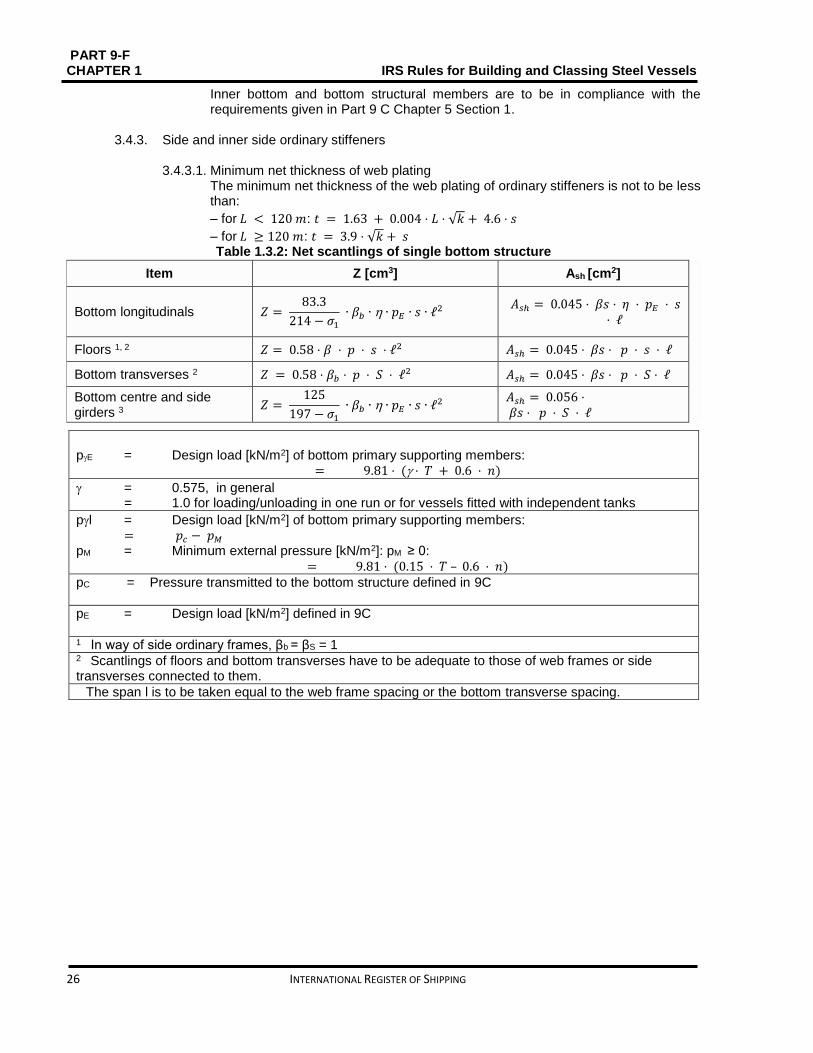
adequate design loads, unless otherwise specified below. 3.4.1.2. Additional requirements for Tankers Type C and N
The minimum net thickness, in mm, of strength deck and bulkhead plating of integrated tanks in the cargo area is not to be less than the values given in Table 1.3.1. Corrosivity of the cargo is to be given due consideration for the plating thickness, unless constructed totally from corrosion-resistant materials or fitted with an approved lining. Table 1.3.1: Minimum net thickness of integrated tanks
Plating Minimum thickness [mm]
Strength deck 𝑡 = 4.4 + 0.016 ⋅ 𝐿 ⋅ √𝑘
Tank bulkhead 𝑡 = 0.8 ⋅ 𝐿1 3⁄ ⋅ √𝑘 + 3.6 ⋅ 𝑠
Watertight bulkhead
𝑡 = 0.68 ⋅ 𝐿1 3⁄ ⋅ √𝑘 + 3.6 ⋅ 𝑠
Wash bulkhead 𝑡 = 0.64 + 0.011 ⋅ 𝐿 ⋅ √𝑘 + 3.6 ⋅ 𝑠
3.4.1.3. Independent tanks
Scantlings of independent tanks are to be determined in conformation to Chapter 5 Section 4, [4.3].
3.4.1.4. Thermal stresses

PART 9 – F IRS Rules for Building and Classing Steel Vessels CHAPTER 1
INTERNATIONAL REGISTER OF SHIPPING 25
Where heated liquids are to be carried in tanks, calculation of thermal stresses is to be done, when carriage temperature of the liquid exceeds 90 °C. The calculations are to be done at the actual carriage temperature and also at the limit temperature specified above. The calculations shall yield the resultant stresses in the hull structure based on water temperature of 0°C and air temperature of −5°C. On the basis of the results of both the above calculations, constructional measures and/or strengthenings will be required.
3.4.1.5. Material factor When steels with minimum guaranteed yield stress ReH other than 235 N/mm2 are used for a vessel, scantlings are to be determined taking into account the material factor as given below:
thickness: see relevant points in the following.
section modulus: 𝑤 = 𝑘 ⋅ 𝑍0
sectional area: 𝐴 = 𝑘 ⋅ 𝐴0
w0, A0 = scantlings corresponding to a steel with a minimum guaranteed yield stress ReH = 235 N/mm2.
3.4.2. Bottom and inner bottom structures 3.4.2.1. Minimum net thickness of web plating
The minimum net thickness [mm] of the web plating of ordinary stiffeners is not to be less than:
– for 𝐿 < 120𝑚 : 𝑡 = 1.63 + 0.004 ⋅ 𝐿 ⋅ √𝑘 + 4.5 ⋅ 𝑠
– for 𝐿 ≥ 120 𝑚: 𝑡 = 3.9 ⋅ √𝑘 + 𝑠
The minimum net thickness [mm] of the web plating of ordinary stiffeners of tankers type C and N is not to be less than:
𝑡 = 0.6. 𝐿1 3⁄ . √𝑘 + 3.6. 𝑠 The minimum net thickness [mm] of plating which forms the web of primary supporting members is not to be less than the value obtained from the formula given below:
𝑡 = 1.14. 𝐿1 3⁄ . √𝑘
3.4.2.2. Net scantlings of bottom and inner bottom structural members in service conditions Table 1.3.2 is to be referred to for obtaining the net scantlings of bottom and inner bottom structural members in service conditions for single bottom structure and Table 1.3.3. for double bottom structure.
3.4.2.3. The net scantlings of bottom and inner bottom structural members that are part of
compartments or structures containing liquid are to be in compliance with the Part 9 C Chapter 5 Section 1
3.4.2.4. Buckling check
PART 9-F CHAPTER 1 IRS Rules for Building and Classing Steel Vessels
26 INTERNATIONAL REGISTER OF SHIPPING
Inner bottom and bottom structural members are to be in compliance with the requirements given in Part 9 C Chapter 5 Section 1.
3.4.3. Side and inner side ordinary stiffeners
3.4.3.1. Minimum net thickness of web plating
The minimum net thickness of the web plating of ordinary stiffeners is not to be less than:
– for 𝐿 < 120 𝑚: 𝑡 = 1.63 + 0.004 ⋅ 𝐿 ⋅ √𝑘 + 4.6 ⋅ 𝑠
– for 𝐿 ≥ 120 𝑚: 𝑡 = 3.9 ⋅ √𝑘 + 𝑠 Table 1.3.2: Net scantlings of single bottom structure
Item Z [cm3] Ash [cm2]
Bottom longitudinals 𝑍 = 83.3
214 − 𝜎1
∙ 𝛽𝑏 ∙ ∙ 𝑝𝐸 ∙ 𝑠 ∙ ℓ2 𝐴𝑠ℎ = 0.045 ⋅ 𝛽𝑠 ⋅ 𝜂 ⋅ 𝑝𝐸 ⋅ 𝑠
⋅ ℓ
Floors 1, 2 𝑍 = 0.58 ⋅ 𝛽 ⋅ 𝑝 ⋅ 𝑠 ⋅ ℓ2 𝐴𝑠ℎ = 0.045 ⋅ 𝛽𝑠 ⋅ 𝑝 ⋅ 𝑠 ⋅ ℓ
Bottom transverses 2 𝑍 = 0.58 ⋅ 𝛽𝑏 ⋅ 𝑝 ⋅ 𝑆 ⋅ ℓ2 𝐴𝑠ℎ = 0.045 ⋅ 𝛽𝑠 ⋅ 𝑝 ⋅ 𝑆 ⋅ ℓ
Bottom centre and side girders 3
𝑍 = 125
197 − 𝜎1
∙ 𝛽𝑏 ∙ ∙ 𝑝𝐸 ∙ 𝑠 ∙ ℓ2 𝐴𝑠ℎ = 0.056 ⋅ 𝛽𝑠 ⋅ 𝑝 ⋅ 𝑆 ⋅ ℓ
pE = Design load [kN/m2] of bottom primary supporting members: = 9.81 ⋅ ( ⋅ 𝑇 + 0.6 ⋅ 𝑛)
= 0.575, in general = 1.0 for loading/unloading in one run or for vessels fitted with independent tanks
pl = Design load [kN/m2] of bottom primary supporting members: = 𝑝𝑐 − 𝑝𝑀
pM = Minimum external pressure [kN/m2]: pM ≥ 0: = 9.81 ⋅ (0.15 ⋅ 𝑇 – 0.6 ⋅ 𝑛)
pC = Pressure transmitted to the bottom structure defined in 9C
pE = Design load [kN/m2] defined in 9C 1 In way of side ordinary frames, βb = βS = 1 2 Scantlings of floors and bottom transverses have to be adequate to those of web frames or side transverses connected to them. The span l is to be taken equal to the web frame spacing or the bottom transverse spacing.

PART 9 – F IRS Rules for Building and Classing Steel Vessels CHAPTER 1
INTERNATIONAL REGISTER OF SHIPPING 27
The minimum net thickness [mm] of the web plating of ordinary stiffeners of tankers type C and N is not to be less than:
𝑡 = 0.6. 𝐿1 3⁄ . √𝑘 + 3.6. 𝑠
3.4.3.2. Net scantlings of side and inner side ordinary stiffeners in service conditions The net scantlings of side ordinary stiffeners in service conditions are to be derived from Table 1.3.4or Table 1.3.5, as applicable.
3.4.3.3. The net scantlings of side and inner side stiffeners being part of compartments or structures carrying liquid are to be in compliance with Part 9 C Chapter 5 Section 1.
3.4.3.4. Buckling check
Side and inner side ordinary stiffeners are to be in compliance with the requirements given in Part 9C Chapter 5 Section 1.
3.4.3.5. Minimum side tank width
The side tank width is not to be less than 600 mm.
3.4.4. Side and inner side primary supporting members 3.4.4.1. Minimum net thickness of web plating
The minimum net thickness of the web plating of primary supporting members is not to be less than:
𝑡 = 1.14. 𝐿1 3⁄ . √𝑘
3.4.4.2. Net scantlings of side and inner side primary supporting members in service conditions The net scantlings of side primary supporting members in service conditions are to be derived from Table 1.3.4 or Table 1.3.5, as applicable.
3.4.4.3. The net scantlings of side and inner side primary supporting members being part of
compartments or structures carrying liquid are to be in compliance with Part 9 C Chapter 5 Section 1.
3.4.4.4. Buckling check Side and inner side primary supporting members are to be in compliance with the requirements given in Part 9 C Chapter Section 1.

PART 9-F CHAPTER 1 IRS Rules for Building and Classing Steel Vessels
28 INTERNATIONAL REGISTER OF SHIPPING
Table 1.3.3: Net scantlings of double bottom structure
Bottom transverses in the side tank
section modulus [cm3] shear sectional area [cm2]
NA NA
𝑍 = 𝑀𝐴𝑋 (𝑤1; 𝑤2)
𝑍1 = 2.32 ∙ 𝛽𝑏 ∙ 𝑝1 ∙ 𝑆 ∙ 𝐵2 ∙ (ℓ − 𝐵2) 𝑍2 = 2.32 ∙ 𝛽𝑏 ∙ 𝑝𝛾1 ∙ 𝑠 ∙ 𝐵2 ∙ (ℓ − 2 ∙ 𝐵2)
𝐴𝑠ℎ = 𝑀𝐴𝑋 (𝐴1; 𝐴2)
𝐴1 = 0.067 ∙ 𝛽𝑠 ∙ 𝑝1 ∙ 𝑆 ∙ ℓ 𝐴2 = 0.067 ∙ 𝛽𝑠 ∙ 𝑝𝛾𝐼 ∙ 𝑆 ∙ (ℓ − 2 ∙ 𝐵3)
Item Parameter Transverse framing Longitudinal framing
Double bottom height [mm] 𝑑 = 𝑀𝐴𝑋 (𝑑1; 𝑑2)
𝑑1 = 34.2 ∙ 𝐴2 ∙ (√2 ∙ 𝑍0
3 ∙ 𝐴𝑎2
+ 1 − 1)
𝑑2 = 600
Floors in the tank 2
section modulus [cm3] thickness [mm] shear sectional area [cm2]
𝑍 = 𝑀𝐴𝑋 (𝑍1; 𝑍2)
𝑍1 = 0.58 𝛽𝑏 ∙ 𝑝1 ∙ 𝑠 ∙ ℓ2
𝑍2 = 0.58 ∙ 𝛽𝑏 ∙ 𝑝𝛾𝐼 ∙ 𝑠 ∙ (ℓ2 − 4 ∙ 𝐵32)
𝑡 = 𝑀𝐴𝑋(𝑡1; 𝑡2)
𝑡1 = 1.14 ∙ 𝐿1
3⁄ ∙ 𝑘0.5 𝑡2 = 𝑑 100⁄
𝐴𝑠ℎ = 𝑀𝐴𝑋 (𝐴1; 𝐴2)
𝐴1 = 0.067 ∙ 𝛽𝑠 ∙ 𝑝1 ∙ 𝑠 ∙ ℓ 𝐴2 = 0.067 ∙ 𝛽𝑠 ∙ 𝑝𝛾𝐼 ∙ 𝑠 ∙ (ℓ − 2 ∙ 𝐵3)
NA
NA NA
Floors in the side tank 2
section modulus [cm3] shear sectional area [cm2]
𝑍 = 𝑀𝐴𝑋 (𝑍1; 𝑍2)
𝑍1 = 2.32 ∙ 𝛽𝑏 ∙ 𝑝1 ∙ 𝑠 ∙ 𝐵2 ∙ (ℓ − 𝐵2)
𝑍2 = 2.32 ∙ 𝛽𝑏 ∙ 𝑝𝛾1 ∙ 𝑠 ∙ 𝐵2
∙ (ℓ − 2 ∙ 𝐵2)
𝐴𝑠ℎ = 𝑀𝐴𝑋 (𝐴1; 𝐴2) 𝐴1 = 0.067 ∙ 𝛽𝑠 ∙ 𝑝1 ∙ 𝑠 ∙ ℓ
𝐴2 = 0.067 ∙ 𝛽𝑠 ∙ 𝑝𝛾𝐼 ∙ 𝑠 ∙ (ℓ − 2 ∙ 𝐵3)
NA NA
Bottom and inner Bottom longitudinals
section modulus [cm3] shear sectional area [cm2]
NA NA
𝑍 =83.3
214 – 𝜎1
∙ 𝛽𝑏 ∙ ∙ 𝑝2 ∙ 𝑠 ∙ ℓ2
𝐴𝑠ℎ = 0.045 ∙ 𝛽𝑠 ∙ ∙ 𝑝2 ∙ 𝑠 ∙ ℓ
Bottom transverses in the tank
section modulus [cm3] thickness [mm] shear sectional area [cm2]
NA NA NA
𝑤 = 𝑀𝐴𝑋 (𝑤1; 𝑤2)
𝑤1 = 0.58 𝛽𝑏 ∙ 𝑝1 ∙ 𝑆 ∙ ℓ2
𝑤2 = 0.58 ∙ 𝛽𝑏 ∙ 𝑝𝛾𝐼 ∙ 𝑆 ∙ (ℓ2 − 4 ∙ 𝐵32)
𝑡 = 𝑀𝐴𝑋(𝑡1; 𝑡2)
𝑡1 = 1.14 ∙ 𝐿1
3⁄ ∙ 𝑘0.5 𝑡2 = 𝑑 90⁄
𝐴𝑠ℎ = 𝑀𝐴𝑋 (𝐴1; 𝐴2)
𝐴1 = 0.067 ∙ 𝛽𝑠 ∙ 𝑝1 ∙ 𝑆 ∙ ℓ
𝐴2 = 0.067 ∙ 𝛽𝑠 ∙ 𝑝𝛾𝐼 ∙ 𝑆 ∙ (ℓ − 2 ∙ 𝐵3)

PART 9 – F IRS Rules for Building and Classing Steel Vessels CHAPTER 1
INTERNATIONAL REGISTER OF SHIPPING 29
Bottom centre and side gird
shear sectional area [cm2]
𝐴𝑠ℎ = 0.051𝛽𝑠 ∙ 𝑝 ∙ 𝑆 ∙ ℓ
p = design load [kN/m2] of bottom primary supporting members
= MAX (p1;pI)
p1 = pE
p2 = design load of bottom and inner bottom longitudinals [kN/m2]:
– in way of ballast tanks: – for bottom longitudinals: p2 = MAX (pE;(pB − pM)) – for inner bottom longitudinals: p2 = MAX (pC; pB)
– elsewhere: – for bottom longitudinals: p2 = pE – for inner bottom longitudinals: p2 = pC
pE = design load [kN/m2] of bottom primary supporting members = 9.81 ⋅ ( ⋅ 𝑇 + 0.6 ⋅ 𝑛) = 0.575 𝑖𝑛 𝑔𝑒𝑛𝑒𝑟𝑎𝑙
= 1.0 for loading/unloading in one run or for vessels fitted with independent tanks
pγI = design load [kN/m2] of bottom primary supporting members = 𝑝𝐶 − 𝑝𝑀
pM = minimum external pressure [kN/m2], pM ≥ 0 = 9.81 ⋅ (0.15 ⋅ 𝑇 – 0.6 ⋅ 𝑛)
pE, pB, pC = pressures transmitted to the double bottom structure,
Aa = cross sectional area of attached inner bottom plating [cm2]
Z0 = section modulus [cm3] of floors or bottom transverses in the tank
ℓ = floor or bottom transverse span [m]:
– where no intermediate longitudinal bulkhead is fitted: ℓ = B – where intermediate longitudinal bulkheads are fitted, l is the distance between outer side and intermediate longitudinal bulkhead, or the distance between intermediate longitudinal bulkheads
B3 = parameter [m] defined as follows: – where no longitudinal bulkhead is fitted: B3 = B2 – where intermediate longitudinal bulkheads are fitted: – for outer tank: 𝐵3 = 0.5 ⋅ 𝐵2 – for other tanks: 𝐵3 = 0 – on vessels fitted with independent tanks, B3 is the distance between the hull outer side
and the independent tank wall
1 The span l is to be taken equal to the web frame or side transverse spacing.
2 In way of ordinary stiffeners, 𝛽𝑏 = 𝛽𝑠 = 1 Note NA = not applicable.

PART 9-F CHAPTER 1 IRS Rules for Building and Classing Steel Vessels
30 INTERNATIONAL REGISTER OF SHIPPING
Table 1.3.4: Side single skin structure
Item w [cm3] Ash [cm2]
Side frames 𝑍 = 𝑀𝐴𝑋 (𝑍1; 𝑍2) 𝑍1 = 0.58 ∙ 𝛽𝑏 ∙ ∙ 𝑠
∙ (1.2 ∙ 𝑘0 ∙ 𝑝𝐸 ∙ ℓ02 + 𝜆𝑡 ∙ 𝑃𝛾𝐸
∙ ℓ𝐹2 )
𝑤2 = 0.58 ∙ 𝛽𝑏 ∙ ∙ 𝑠 ∙ (𝜆𝑏 ∙ 𝑝2 ∙ ℓ2 + 𝜆𝑡 ∙ 𝑃𝛾𝐼 ∙ ℓ𝐹2 )
𝐴𝑠ℎ = 𝑀𝐴𝑋 (𝐴1; 𝐴2) 𝐴1 = 0.08 ∙ 𝛽𝑠 ∙ ∙ 𝑘0 ∙ 𝑝𝐸 ∙ 𝑠 ∙ ℓ0
𝐴2 = 0.058 ∙ 𝜆𝑠 ∙ 𝛽𝑠 ∙ 𝑝2 ∙ 𝑠 ∙ ℓ
Side longitudinals
𝑍 =83.3
214 − 𝜎1
∙ 𝛽𝑏 ∙ ∙ 𝑝 ∙ 𝑠 ∙ ℓ2 𝐴𝑠ℎ = 0.045 ∙ 𝛽𝑠 ∙ ∙ 𝑝 ∙ 𝑠 ∙ ℓ
Side web frames Side transverses 1
𝑍 = 𝑀𝐴𝑋 (𝑤1; 𝑤2)
𝑍1 = 1.96 ∙ 𝛽𝑏 ∙ 𝑘0 ∙ 𝑝𝐸 ∙ 𝑆 ∙ ℓ02
𝑍2 = 1.63 ∙ 𝜆𝑏 ∙ 𝛽𝑏 ∙ 𝑝2 ∙ 𝑆 ∙ ℓ2
𝐴𝑠ℎ = 𝑀𝐴𝑋 (𝐴1; 𝐴2)
𝐴1 = 0.063 ∙ 𝛽𝑠 ∙ 𝑘0 ∙ 𝑝𝐸 ∙ 𝑆 ∙ ℓ0 𝐴2 = 0.045 ∙ 𝜆𝑠 ∙ 𝛽𝑠 ∙ 𝑝2 ∙ 𝑆 ∙ ℓ
Side stringers 2
𝑍 =125
197 − 𝜎1
∙ 𝛽𝑏 ∙ 𝑝 ∙ 𝑆 ∙ ℓ2 𝐴𝑠ℎ = 0.056 ∙ 𝛽𝑠 ∙ 𝑝 ∙ 𝑆 ∙ ℓ
p = design load of side structural members [kN/m2] = MAX (pE; p2)
pE = external pressure transmitted to the side structural members, defined in ****. For vertical structural members: 𝑝𝐸 = 4.9 ⋅ (𝑇 − 𝐻𝐹 + 0.6 ⋅ 𝑛)
p2 = design load [kN/m2] = |pC − pM|
pC = 0 for vessels with independent tanks
pE = floor design load [kN/m2] = 9.81 ⋅ ( ⋅ 𝑇 + 0.6 ⋅ 𝑛) = 0.575 in general = 1.0 for loading/unloading in one run or for vessels fitted with independent tanks
pI = floor design load [kN/m2] = pC − pM
pM = minimum external pressure [kN/m2], pM ≥ 0:
– for z ≤ 0.15⋅T: 𝑃𝑀 = 9.81 ⋅ (0.15 ⋅ 𝑇 − 𝑧 – 0.6 ⋅ 𝑛) – for z > 0.15⋅T: pM = 0
ℓ0 = 𝑇 − 𝐻𝐹 + 0.6 ⋅ 𝑛 ℓF = floor span [m]
HF = floor height or bottom transverse height [m]
k0 = coefficient given by the formula: = 1 + (ℓ − ℓ0) / ℓ0
λt = coefficient – in transverse framing:
= 0.1 ∙ (0.8 − ℓ2
ℓ𝐹2), 𝜆𝑡 ≥ 0
– in combination framing: λt = 0
pC = pressure transmitted to the double side structure, defined in 9C 1 Scantlings of web frames and side transverses at the lower end have to be adequate to those of floors or bottom transverses connected to them, and at the upper end they are to be the same as those of the deck transverses connected to them. 2The span of side stringers is to be taken equal to the side transverse spacing or the web frame spacing.

PART 9 – F IRS Rules for Building and Classing Steel Vessels CHAPTER 1
INTERNATIONAL REGISTER OF SHIPPING 31
Table 1.3.5: Side double skin structure
Item w [cm3] Ash [cm2]
Side frames subjected to external load 𝑍 = 0.7 ∙ 𝛽𝑏 ∙ 𝑘0 ∙ 𝑝 ∙ 𝑠 ∙ ℓ02 𝐴𝑠ℎ = 0.08 ∙ 𝛽𝑠 ∙ 𝑘0 ∙ 𝑝 ∙ 𝑠 ∙ ℓ0
Side frames (other loading cases) and inner side frames
𝑍 = 0.58 ∙ 𝜆𝑏 ∙ 𝛽𝑏 ∙ 𝑝 ∙ 𝑠 ∙ ℓ2 𝐴𝑠ℎ = 0.058 ∙ 𝜆𝑠 ∙ 𝛽𝑠 ∙ 𝑝 ∙ 𝑠 ∙ ℓ
Side longitudinal Inner side longitudinals
𝑍 =83.3
214 − 𝜎1
∙ 𝛽𝑏 ∙ ∙ 𝑝 ∙ 𝑠 ∙ ℓ2 𝐴𝑠ℎ = 0.045 ∙ 𝛽𝑠 ∙ ∙ 𝑝 ∙ 𝑠 ∙ ℓ
Side web frames and side transverses subjected to external load
𝑍 = 0.7 ∙ 𝛽𝑏 ∙ 𝑘0 ∙ 𝑝 ∙ 𝑆 ∙ ℓ02 𝐴𝑠ℎ = 0.08 ∙ 𝛽𝑠 ∙ 𝑘0 ∙ 𝑝 ∙ 𝑆 ∙ ℓ0
Side web frames, inner side web frames, side transverses and inner side transverses in other loading cases
𝑍 = 0.58 ∙ 𝜆𝑏 ∙ 𝛽𝑏 ∙ 𝑝 ∙ 𝑆 ∙ ℓ2 𝐴𝑠ℎ = 0.045 ∙ 𝜆𝑠 ∙ 𝛽𝑠 ∙ 𝑝 ∙ 𝑆 ∙ ℓ
Plate web frames subjected to external load 𝑍 = 1.96 ∙ 𝛽𝑏 ∙ 𝑘0 ∙ 𝑝 ∙ 𝑆 ∙ ℓ02 𝐴𝑠ℎ = 0.063 ∙ 𝛽𝑠 ∙ 𝑝 ∙ 𝑆 ∙ ℓ0
Plate web frames in other loading cases 𝑍 = 1.63 ∙ 𝜆𝑏 ∙ 𝛽𝑏 ∙ 𝑝 ∙ 𝑆 ∙ ℓ2 𝐴𝑠ℎ = 0.045 ∙ 𝜆𝑠 ∙ 𝛽𝑠 ∙ 𝑘0 ∙ 𝑝 ∙ 𝑆∙ ℓ
Side stringers 1
Inner side stringers 1 𝑍 =
125
197 − 𝜎1
∙ 𝛽𝑏 ∙ 𝑝 ∙ 𝑆 ∙ ℓ2 𝐴𝑠ℎ = 0.056 ∙ 𝛽𝑠 ∙ 𝑝 ∙ 𝑆 ∙ ℓ
p = design load of double side structural members [kN/m2]: – for inner side structure:
– in way of ballast tanks: p = MAX (pC; pB) – elsewhere: p = pC
– pC = 0 for vessels with independent tanks – for side structure:
– in way of ballast tanks: p = MAX (pE; (pB − pM)) – elsewhere: p = pE
pE = external pressure transmitted to the side structural members For vertical structural members: 𝑝𝐸 = 4.9 ⋅ (𝑇 − 𝐻𝐹 + 0.6 ⋅ 𝑛) ℓ0 = 𝑇 − 𝐻𝐹 + 0.6 ⋅ 𝑛
HF = floor height or bottom transverse height [m]
k0 = coefficient given by the formula: = 1 + (ℓ − ℓ0) / ℓ0
pM = minimum external pressure [kN/m2], pM ≥ 0:
– for z ≤ 0.15 ⋅ T: 𝑃𝑀 = 9.81 ⋅ (0.15 ⋅ 𝑇 − 𝑧 – 0.6 ⋅ 𝑛)
– for z > 0.15 ⋅ T: pM = 0
pB, pC = pressures transmitted to the double side structure 1The span of side stringers is to be taken equal to the side transverse spacing or the web frame spacing.

PART 9-F CHAPTER 1 IRS Rules for Building and Classing Steel Vessels
32 INTERNATIONAL REGISTER OF SHIPPING
3.5. Transverse rings
3.5.1. General
3.5.1.1. The strength check of the transverse rings is to be done by direct calculation as per Part 9 C Chapter 5 Section 1. The requirements of 3.4.2 to 3.4.4 are to be complied with, in particular.
3.5.1.2. Following loading conditions are to be considered: – Light vessel draught, fully loaded tank subjected to cargo load as per Part 9 C Chapter 5 Section 1, [1.2]. – Fully loaded tank subjected to test pressure as given in Part 9C Chapter 2 Section 8 – Fully loaded vessel draught, empty tank subjected to external pressure, as per Part 9 C Chapter 5 Section 1, [1.2].
3.5.2. Floors and bottom transverses in way of rings Following checks are to be done: – Buckling strength of unstiffened web. – Level of shear stresses, particularly, in way of holes and passage of longitudinal. – Continuity of double bottom in the side tank.
3.5.3. Web frames and side transverses in way of rings For side primary supporting members, level of bending stresses and shear stresses in way of holes and passage of longitudinals are to be checked.
3.5.4. Strong beams and deck transverses in way of rings Following checks are to be done:
– Buckling strength of unstiffened web. – Level of bending stresses and shear stresses, particularly, in path of holes and passage of longitudinal. – Continuity of structure and lateral support of deck transverses, specifically, when flange of the deck transverse is a round bar.
3.5.5. Pillars 3.5.5.1. Strong beams and deck transverses in the path of rings are to be supported by
pillars. As per Part 9 C Chapter 6 Section 1, the pillar scantlings are to be determined. It is required to examine the pillars and their attachments for tensile stressing resulting from the relevant pressure related to the respective vessel type.
3.5.5.2. It is recommended to avoid tubular pillars in the cargo tanks. Also, these are not
permitted on tank vessels intended to carry flammable liquids or chemicals. 3.5.5.3. The pillars are to be attached to the girders and the floor plates located below with
help of welding.
3.5.6. Break in the deck A reinforced deck transverse, a transverse bulkhead or a pillar is to be fitted in path of the deck break.

PART 9 – F IRS Rules for Building and Classing Steel Vessels CHAPTER 1
INTERNATIONAL REGISTER OF SHIPPING 33
3.6. Structural arrangements
3.6.1. Vessels with integrated tanks, transverse framing system
3.6.1.1. Beams
Beams are to be fitted at every frame. These are to be discontinuous in way of longitudinal bulkheads, to which they are connected with brackets. Deck beams are not to be discontinuous in way of expansion tanks, unless efficient compensations are provided.
3.6.1.2. Strong beams As a Rule, strong beams are to have same scantlings as side web frames to which they are connected by brackets or equivalent arrangement, so as to ascertain strength continuity.
3.6.1.3. Web frames The spacing between the web frames is not to be more than 4m, considering the frames are supported at mid-span by a stringer.
3.6.1.4. Floors Floors are to be fitted at every frame. They are to be discontinuous in way of bulkheads to which they are connected using brackets or other equivalent arrangement that ascertains strength continuity. An adequate number of limber holes are to be cut in floors, longitudinals and transverses for proper draining of cargo to the pump suctions.
3.6.2. Vessels with integrated tanks, longitudinal framing system 3.6.2.1. Side transverses
The spacing between side transverses is not to be more than 3 m. The span of side shell strength transverses is to be taken equal to the vertical distance between deck and bottom.
3.6.2.2. Deck longitudinals The deck longitudinals are to be continuous through expansion tanks, unless compensations are given.
3.6.3. Vessels with integrated tanks, combination system
3.6.3.1. Web frames
It is recommended to arrange side shell and longitudinal bulkhead web frames in the path of bottom and deck transverses.
3.6.4. Vessels with independent tanks 3.6.4.1. General
Vessels with independent tanks are to be built on transverse framing system. Instead, when a longitudinal framing system is used, it is to be specially considered by IRS.

PART 9-F CHAPTER 1 IRS Rules for Building and Classing Steel Vessels
34 INTERNATIONAL REGISTER OF SHIPPING
3.6.4.2. Floors Floors which are not in contact with tanks, for instance, floors located between tanks and floors at hold ends, at least two (2) keelsons with inter-costal plating are to be provided. The keelsons are to be approximately fitted at 1/3rd of the width and extending at least over three (3) frame spaces beyond tank end bulkheads.
3.6.4.3. Frames The side frames may be inside or outside the tank. When tank longitudinal sides are framed vertically, stiffeners are to form continuous frames with the top and bottom stiffeners, irrespective of the frames are or not connected by brackets. The vertical or horizontal stiffeners of transverse sides are to be welded on to the perpendicular tank sides, either directly or using brackets extending up to the first stiffener of previous sides. To ascertain proper contact between vessel bottom and tank plates, the bottom structure is to be adequately stiffened.
3.6.5. Fastening of self-supporting tanks 3.6.5.1. Chocking of tanks
The tank seatings are to be so constructed such that it is impossible to move the tanks in relation to the vessel structure. Tanks are to be supported by floors or bottom longitudinals. When a stringer is chocked against tanks in way of some web frames or side shell transverses, chocking may consist of a bolted assembly. In case of applying wedges of hard wood or synthetic material capable of conveying the chocking stress, arrangements to avoid an accidental shift during navigation are to be provided.
3.6.5.2. Anti-flotation arrangements which are sufficient to withstand an upward force caused by an empty tank in a hold space flooded to the damage draught of the vessel, without plastic deformation likely to endanger the hull structure are to be provided for independent tanks.
3.6.5.3. The strength check of the seatings and stays is to be done in conformation to E., using partial safety factor ηR = 1.5.
3.6.5.4. To avoid stress concentrations on the tank walls, and care is to be taken to ascertain that tank seatings do not hinder the contraction of the tank when it is cooled down to transport temperature.
3.6.6. Double hull arrangements
3.6.6.1. General For proper survey and maintenance, all parts of the cargo zone are to be well ventilated and easily accessible.
3.6.6.2. Access to double bottom Ensure that all the parts of double bottom are easily accessible, manholes may be cut in the floors and side girders and which are to be cut smooth along a well-rounded design. Moreover, these are strictly not to be greater than that necessary
PART 9 – F IRS Rules for Building and Classing Steel Vessels CHAPTER 1
INTERNATIONAL REGISTER OF SHIPPING 35
to provide the human access. Where manholes of greater sizes are required, edge reinforcement by means of flat bar rings or other stiffeners may be provided. As a Rule, the manholes height is not to exceed 0.6 times the floor height or girder height. In the floors, manholes are to be located at half the floor height and in a region extending on 0.2⋅B from the axis of the vessel, on both sides. On the central girder, its distance to the nearest side of cutting is not to be less than the double bottom height. Manholes in the side girders are to be located at half the girder height and in the middle of two successive web frames. If there is no web frame, their distance from the transverse bulkheads of the side tanks is not to be less than 1.5 m. IRS may waive this rule subject to direct calculation of the shear stresses.
3.6.6.3. Access to side tanks Manholes are to be cut in the plate webs and stringer plate to provide easy access to all parts of the side tanks. Smooth openings with a well-rounded design in the stringer plate are to be arranged clear of the hatch corners. They are to be strengthened by thick plates or by doubling plates.
3.6.6.4. Access to tanks As far as practicable, it has to be ascertained that for proper survey and maintenance of cargo tanks, permanent or removable means of access are available on board.
3.6.6.5. Floor reinforcement Where the inner side plating does not extend to the bottom plating, floors of vessels built-in the transverse system are to be stiffened, at each frame, in way of the double hull shell plating, using a section, the net sectional area of which [cm2] is not to be less than:
𝐴 = 0.01. 𝑏. 𝑡𝐹 b = section height [mm]: 𝑏 = 100. 𝐻𝐷
where HD is the double bottom height [m ] tF= Net thickness of floor web [mm]
3.6.7. Expansion tanks
At the mid-length, each tank is to be provided with an expansion tank whose height is not to be less than 0.5 m above tank top. IRS is required to especially examine scantlings of expansion tank covers.
3.7. Subdivision
3.7.1. General
3.7.1.1. Bulkheads adjacent to cofferdams, tanks and hold are to be welded or assembled using an approved process. These bulkheads are not to have any openings.

PART 9-F CHAPTER 1 IRS Rules for Building and Classing Steel Vessels
36 INTERNATIONAL REGISTER OF SHIPPING
3.7.1.2. In compliance with Part 9 C Chapter 5 Section 4., the bulkhead scantlings are to be determined taking into account additional requirements given in 3.7.2 and 3.7.3.
3.7.2. Minimum thickness of bulkhead plating
3.7.2.1. Minimum plating thickness Using the following formula, the net thickness [mm] of liquid cargo tank bulkheads is to be not less than that obtained:
𝑡 = 1.36 + 0.011. 𝐿. 𝑘0.5 + 3.6. 𝑠 In cargo tank area, including cofferdams, the net thickness of plates and structural members in spaces containing water are not to be less than 4.4 - 5 mm.
3.7.3. Minimum net thickness of structural
3.7.3.1. Ordinary stiffeners Using the following formula, the minimum net thickness [mm] of the web plate of ordinary stiffeners is to be obtained:
𝑡 = 0.61. 𝐿1 3⁄ . 𝑘0.5 + 3.6. 𝑠
3.7.3.2. Primary supporting members Using the following formula, the minimum net thickness [mm] of the web plate of primary supporting members is to be obtained:
𝑡 = 1.14. 𝐿1 3⁄ . 𝑘0.5
3.7.4. Corrugated bulkheads 3.7.4.1. General
Instead of plane bulkheads that are provided with stiffeners, corrugated bulkheads, determined as per Part 9 C Chapter 5 Section 4, may be built in.
3.7.4.2. Ends of cargo zone The inner longitudinal side has to be extended into the cofferdam. Moreover, if using brackets, it is to be extended in the fore and aft vessel.

PART 9 – F IRS Rules for Building and Classing Steel Vessels CHAPTER 1
INTERNATIONAL REGISTER OF SHIPPING 37
SECTION 4 CONTAINER VESSELS Contents
Contents
4.1. Symbols ............................................................................................................................................ 38
4.2. General ............................................................................................................................................. 38
4.3. Structure arrangements .................................................................................................................... 38
4.4. Design loads ..................................................................................................................................... 40
4.5. Hull scantlings................................................................................................................................... 41
4.6. Direct calculation .............................................................................................................................. 42

PART 9-F CHAPTER 1 IRS Rules for Building and Classing Steel Vessels
38 INTERNATIONAL REGISTER OF SHIPPING
4.1. Symbols
L = Rule length [m] defined in Part 9C Chapter 1, Section 1, [1.2.1]. B = Breadth [m] defined in Part 9C Chapter 1, Section 1, [1.2.1]. D = Depth [m] defined in Part 9C Chapter 1, Section 1, [1.2.1]. T = Draught [m] defined in Part 9C Chapter 1, Section 1, [1.2.1]. t = Net thickness [mm] of plating; k = Material factor defined in Part 9 C Chapter 2 Section 2, [2.3].
4.2. General
4.2.1. Application 4.2.1.1. The type and service notation Container is assigned, in compliance with Part 9 A
Chapter 2 Section 2,[2.3.1.2], to vessels intended to carry dry unit cargoes. 4.2.1.2. Vessels dealt herein this Section are to be in compliance with the requirements
given in Part 9 A, B , C,D, E as applicable, and for the specific requirements, applicable to container vessels.
4.2.1.3. Applicable requirements given in Section 1 & Section 2. are also to be conformed
to.
4.2.2. Stability Compliance with the applicable stability requirements as per Chapter 3 Section 5. is to be proved.
4.3. Structure arrangements
4.3.1. Strength principles 4.3.1.1. Local reinforcements
Local reinforcements of the hull structure are to be provided under container corners and in way of fixed cargo securing devices and cell guides, if fitted. The designer shall indicate all forces applied on the fixed cargo securing devices.
4.3.1.2. Structural continuity In double hull vessels, inner side is to extend as far aft as possible and be tapered at the ends.
4.3.2. Bottom structure 4.3.2.1. Floor and girder spacing
It is recommended that the floor spacing is to be such that floors are located in the path of the container corners. Floors are also to be fitted in the way of watertight bulkheads. Girders are to be fitted in way of the container corners.
4.3.2.2. Strength continuity Adequate strength continuity of floors and bottom transverses is to be ascertained in way of the side tank with help of brackets.

PART 9 – F IRS Rules for Building and Classing Steel Vessels CHAPTER 1
INTERNATIONAL REGISTER OF SHIPPING 39
4.3.2.3. Reinforcements in way of cell guides
Doublers, brackets or equivalent reinforcements are required to stiffen the structures of the bottom and inner bottom on which cell guides rest.
4.3.3. Fixed cell guides 4.3.3.1. General
Containers may be secured within fixed cell guides, permanently secured to the hull structure by welding, to prevent tipping and horizontal sliding.
4.3.3.2. Arrangement of fixed cell guides Vertical guides consist of sections with equal sides of not less than 12 mm thickness, extended for an adequate height to render uniform support to containers. Guides are to be connected to each other and to the supporting structures of the hull with the help of cross-ties and longitudinal members to prevent deformation due to the forces transmitted by containers. In general, the spacing between cross-ties connecting the guides is not to exceed 5 meters, and their position is to coincide with that of the container corners, if possible (see Fig1.4.1).
Fig. 1.4.1 Typical structure of cell guides
At one or more points, cross-ties are to be longitudinally restrained so that their elastic deformation due to longitudinal thrust of containers does not exceed 20 mm at any point. In stowing containers within the guides, maximal clearance between guide and container is not to exceed 38 mm in the longitudinal direction and 25 mm in the transverse direction.
PART 9-F CHAPTER 1 IRS Rules for Building and Classing Steel Vessels
40 INTERNATIONAL REGISTER OF SHIPPING
The upper end of the guides is to be fitted with a block to facilitate easy entry of the containers. This appliance shall have sturdy construction as it needs to withstand impact and chafing forces.
4.3.4. Fixed cargo securing devices 4.3.4.1. When containers are carried on the hatch covers and on deck, container-
supporting members of adequate scantlings are to be fitted. 4.3.4.2. Documentation to be submitted
A list and/or plan of all the fixed securing devices, indicating their location on board is to be provided. For every fixed securing device, following information is to be indicated: – Material; – Type designation; – Breaking load; – Sketch of the device; – Maximum securing load.
4.3.5. Hatch covers carrying containers Efficient retaining arrangements are to be provided to prevent translation of the hatch cover under the action of the longitudinal and transverse forces exerted by the stacks of containers on the cover. These retaining arrangements are to be located in way of the hatch coaming side brackets. Solid fittings are to be welded on the hatch cover where the corners of the containers are resting. These parts are intended to transport the loads of the container stacks onto the hatch cover on which they are resting and also to prevent horizontal translation of the stacks using special intermediate parts arranged between the supports of the corners and container corners.
4.4. Design loads
4.4.1. Design torsional torque Where Designer does not provide some specific data, the design still water torsional torque induced by the non-uniform distribution of cargo, consumable liquids and ballast is to be
obtained at the midship section [kN⋅m] from the formula given below:
𝑀𝑇 = 31.4 . 𝑛𝑆 . 𝑛𝑇 . 𝐵 nS = Number of container stacks over the breadth B. nT = Number of container tiers in cargo hold amid-ships (including containers on hatch
covers).
4.4.2. Force on containers 4.4.2.1. The force Fi applied to one container located at the level "I", as defined in Fig.
1.4.5, is to be determined. Designer is required to define the mass of the containers. Where the mass of loaded containers is not known, following values may be used: – For 20 feet containers: mi = 17 t.

PART 9 – F IRS Rules for Building and Classing Steel Vessels CHAPTER 1
INTERNATIONAL REGISTER OF SHIPPING 41
– For 40 feet containers: mi = 27 t; Where empty containers are stowed at the top of a stack, the following values may be used: – 0.08 times the weight of a loaded container, in case of empty aluminum containers; – 0.14 times the weight of a loaded container, in case of empty steel containers
4.4.2.2. Stacks of containers Following formula may be used to obtain the force transmitted at the corners of such stack:
𝑃 = 𝐹4⁄
𝐹 = ∑ 𝐹𝑖
𝑁
𝑖=1
N = Number of containers in a stack
Figure 1.4.5 Container levels in a stack
4.4.2.3. Securing load
The scantling load of securing devices is to be determined assuming angle of list of 12°.
4.5. Hull scantlings
4.5.1. General
4.5.1.1. In general, the hull scantlings and arrangements are to be in compliance with Part 9 C Chapter 5.
PART 9-F CHAPTER 1 IRS Rules for Building and Classing Steel Vessels
42 INTERNATIONAL REGISTER OF SHIPPING
4.5.1.2. Scantlings of structural members subjected to concentrated loads are to be determined by direct calculation as per. The requirements of 6 are to be conformed to, specifically.
4.5.1.3. Where the operating conditions (loading/unloading sequence as well as consumable and ballast distribution) are likely to induce excessive torsional torque, the torsional strength is to be checked, using the design torsional torque derived from 4.4.1.
4.5.2. Container seating
Using the following formulae, net thickness [mm] of container seating, if fitted, is not to be less than that of the adjacent inner bottom plating nor than the thickness obtained:
tWL = 0.8. CWL ∙ √k ∙ nC ∙ P
CWL = coefficient
2.15 –0.05 ∙ ℓ
s+ 0.02 ∙ (4 −
ℓ
s) ∙ α0.5 − 1.75 ∙ α0.25
Where ℓ
𝑠 is to be taken not greater than 3
α =AT
ℓ ∙ s
AT = area of a stack of container corner [m2] nC = number of stacks of container corners on the seating ℓ = MAX (a, b) s = MIN (a, b) a, b = Spacings [m] of container supporting members
4.6. Direct calculation
4.6.1. General
Following requirements apply for the grillage analysis of primary supporting members subjected to concentrated loads.
4.6.2. Loading cases
4.6.2.1. Bottom structure
Following loading conditions are to be considered in the analysis of the bottom primary supporting members: – Maximum vessel draught T, without containers;
– Full container load and scantling draught equal to 0.575 ⋅ T.
4.6.2.2. Deck structure
When containers are loaded on the deck, analysis of the deck structure is to be done taking into account full container load.
4.6.3. Structure checks
Following checks are to be done: – Level of bending stresses and shear stresses in the path of holes and passage of longitudinal particularly; – Buckling strength of unstiffened web; – Continuity of double bottom in the side tank, for bottom structure.

PART 9 – F IRS Rules for Building and Classing Steel Vessels CHAPTER 1
INTERNATIONAL REGISTER OF SHIPPING 43
SECTION 5 RORO VESSELS Contents
5.1. Symbols ............................................................................................................................................ 44
5.2. General ............................................................................................................................................. 44
5.3. Vessel arrangements ........................................................................................................................ 44
5.4. Hull scantlings................................................................................................................................... 45

PART 9-F CHAPTER 1 IRS Rules for Building and Classing Steel Vessels
44 INTERNATIONAL REGISTER OF SHIPPING
5.1. Symbols L = Rule length [m] defined in Part 9C Chapter 1, Section 1, [1.2.1]. B = Breadth [m] defined in Part 9C Chapter 1, Section 1, [1.2.1]. D = Depth [m] defined in Part 9C Chapter 1, Section 1, [1.2.1]. T = Draught [m] defined in Part 9C Chapter 1, Section 1, [1.2.1]. t = Net thickness [mm] of plating; s = Spacing [m] of ordinary stiffeners; S = Spacing [m] of primary supporting members; ℓ = Span [m] of ordinary stiffeners or primary supporting members; σ1= Hull girder normal stress [N/mm2]; Z = Net section modulus [cm3] of ordinary stiffeners or primary supporting members; Ash= Net web shear sectional area [cm2]; k = Material factor defined in Part 9 C Chapter 2 Section 2, [2.3]; z = Z co-ordinate [m] of the calculation point;
MH= Design bending moment [kN⋅m] in hogging condition;
MS= Design bending moment [kN⋅m] in sagging condition; F = Wheeled force [kN] defined in ****
5.2. General
5.2.1. Application
5.2.1.1. The type and service Notation RoRo Vessel is assigned, as Part 9A Chapter 2 Section 2, [2.3.1.5] to vessels intended to carry wheeled vehicles.
5.2.1.2. Vessels dealt herein this Section are meet the requirements stated in Part 9 A , B, C, D, E, as applicable, and with the requirements of this Section, which are specific to Ro-Ro vessels.
5.2.1.3. Applicable requirements stated in Section 1, and Section 2 are also to be complied with.
5.2.2. Stability IRS may require enough proof of stability depending on the vessel’s design and operating conditions.
5.3. Vessel arrangements
5.3.1. Sheathing Sheathing made of wood is recommended for trucks and unusual vehicles. Besides, a piece of wood of suitable thickness should be provided under each crutch that helps in distributing the mass over the plate and the nearest stiffeners.
5.3.2. Drainage of ro-ro cargo spaces, intended for the carriage of motor vehicles with fuel in their tanks for their own propulsion 5.3.2.1. Scupper draining
Scuppers from cargo spaces intended for carrying motor vehicles with fuel in their tanks for their own propulsion are not to be led to machinery or other spaces where sources of ignition may be present.
5.3.3. Hull structure
PART 9 – F IRS Rules for Building and Classing Steel Vessels CHAPTER 1
INTERNATIONAL REGISTER OF SHIPPING 45
5.3.3.1. Framing
The strength deck and the bottom are to be longitudinally framed. IRS shall consider adoption of a transverse framing system for such structures, on a case-by-case basis.
5.4. Hull scantlings
5.4.1. General 5.4.1.1. The hull scantlings and arrangements are to conform to Part 9 C Chapter 5 . 5.4.1.2. Scantlings of structural members and plating subjected to wheeled loads are to be
determined as per 5.4.2 to 5.4.4.
5.4.2. Plating 5.4.2.1. The net thickness [mm] of plate panels subjected to wheeled loads is to be
computed from Table 1.5.2, where:
𝑡𝑊𝐿 = 𝑃𝑙𝑎𝑡𝑖𝑛𝑔 𝑛𝑒𝑡 𝑡ℎ𝑖𝑐𝑘𝑛𝑒𝑠𝑠 [𝑚𝑚]
𝑡𝑊𝐿 = 0.8 . 𝐶𝑊𝐿 . √𝑘. 𝑛𝑝. 𝐹
𝐶𝑊𝐿 = 𝑐𝑜𝑒𝑓𝑓𝑖𝑐𝑖𝑒𝑛𝑡
= 2.15 − 0.05 . ℓ
𝑠+ 0.02 (4 −
ℓ
𝑠) . 𝛼0.5 − 1.75 . 𝛼0.25
Where ℓ
𝑠 is to be taken not greater than 3.
𝛼 = 𝐴𝑇
ℓ. 𝑠
𝐴𝑇 = 𝑇𝑦𝑟𝑒 𝑝𝑟𝑖𝑛𝑡 𝑎𝑟𝑒𝑎 [𝑚2] In case of double or triple wheels, area is that corresponding to the group of wheels.
𝑛𝑝 = Number of wheels on plate panel, taken equal to:
1 in case of a single wheel;
Equal to the number of wheels in a group of wheels, in the case of double or triple wheels.
5.4.2.2. Tyre print area
When the tyre imprint area is unknown, it may be taken equal to:
𝐴𝑇 = 9.81 .𝑛𝑝 . 𝑄𝐴
𝑛𝑤 .𝑃𝑇
𝑄𝐴 = 𝐴𝑥𝑙𝑒 𝑙𝑜𝑎𝑑 [𝑡]; 𝑛𝑤 = Number of wheels for the axle considered;
𝑝𝑇 = Tyre pressure [kN
m2].
When designer has not indicated the tyre pressure, it may be taken as given in Table 1.5.1.
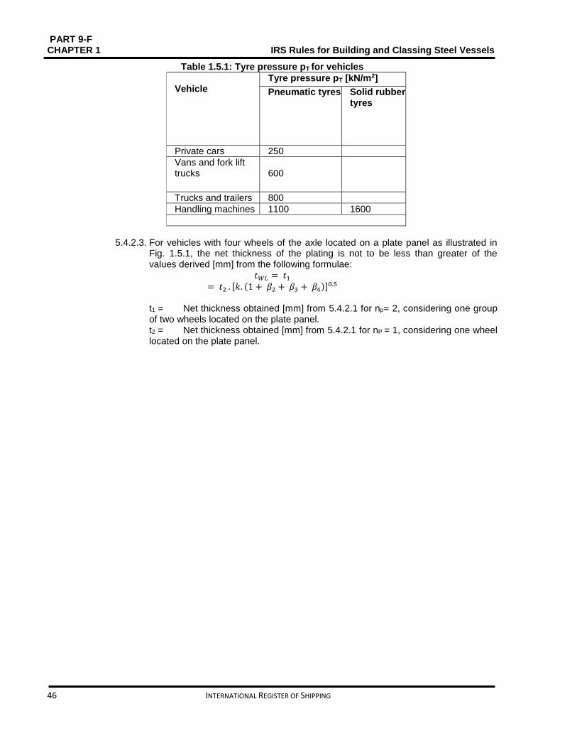
PART 9-F CHAPTER 1 IRS Rules for Building and Classing Steel Vessels
46 INTERNATIONAL REGISTER OF SHIPPING
Table 1.5.1: Tyre pressure pT for vehicles
Vehicle
Tyre pressure pT [kN/m2]
Pneumatic tyres Solid rubber tyres
Private cars 250
Vans and fork lift trucks
600
Trucks and trailers 800
Handling machines 1100 1600
5.4.2.3. For vehicles with four wheels of the axle located on a plate panel as illustrated in
Fig. 1.5.1, the net thickness of the plating is not to be less than greater of the values derived [mm] from the following formulae:
𝑡𝑊𝐿 = 𝑡1
= 𝑡2 . [𝑘. (1 + 𝛽2 + 𝛽3 + 𝛽4)]0.5
t1 = Net thickness obtained [mm] from 5.4.2.1 for np= 2, considering one group of two wheels located on the plate panel. t2 = Net thickness obtained [mm] from 5.4.2.1 for nP = 1, considering one wheel located on the plate panel.

PART 9 – F IRS Rules for Building and Classing Steel Vessels CHAPTER 1
INTERNATIONAL REGISTER OF SHIPPING 47
Table 1.5.2: Net thickness of plating subjected to wheeled loads [mm]
Item Transverse framing Longitudinal framing
Inner bottom plating
𝑡 = 𝑀𝐴𝑋 (𝑡𝑖)
𝑡1 = 1.5 + 0.016 ∙ 𝐿 ∙ 𝑘0.5 + 3.6 ∙ 𝑠 𝑡2 = 𝑡𝑤𝐿
and, for 𝐿 ≥ 40𝑚1:
𝑡3 = 68 ∙𝑠
𝑘2
∙ √𝑀𝐻
𝑍𝐷𝐵
𝑡 = 𝑀𝐴𝑋 (𝑡𝑖)
𝑡1 = 1.5 + 0.016 ∙ 𝐿 ∙ 𝑘0.5 + 3.6 ∙ 𝑠 𝑡2 = 𝑡𝑤𝐿
and, for 𝐿 ≥ 40𝑚1:
𝑡3 = 39 ∙ 𝑠 ∙ √𝑀𝐻
𝑍𝐷𝐵
Deck plating
𝑡 = 𝑀𝐴𝑋 (𝑡𝑖)
𝑡1 = 0.9 + 0.034 ∙ 𝐿 ∙ 𝑘0.5 + 3.6𝑠 𝑡2 = 𝑡𝑤𝐿
and, for 𝐿 ≥ 40𝑚1:
𝑡3 = 74 ∙𝑠
𝑘2
∙ √𝑀𝑠
𝑍 𝐷
if 𝑡3 𝑠⁄ > 23.9 𝑘0.5 ∙ 𝑘2⁄ :
𝑡3 =7.76 ∙ 𝑘0.5 ∙ 𝑠
𝑘2 ∙ √0.21 −𝑀𝑠
𝑍𝐷
𝑡 = 𝑀𝐴𝑋 (𝑡𝑖)
𝑡1 = 0.57 + 0.031 ∙ 𝐿 ∙ 𝑘0.5 + 3.6𝑠 𝑡2 = 𝑡𝑤𝐿
and, for 𝐿 ≥ 40𝑚1:
𝑡3 = 39 ∙ 𝑠 ∙ √𝑀𝑆
𝑍𝐷
If 𝑡3 > 12.5 𝑘0.5⁄
𝑡3 =4.1 ∙ 𝑘0.5 ∙ 𝑠
√0.21 −𝑀𝑠
𝑍𝐷
𝑘2 = 1 + 𝛼2 𝛼 = 𝑠 / 𝑏 b = unsupported plate width in y direction [m] tWL = net thickness [mm] as defined in 5.4.2.1 ZD = deck net hull girder section modulus [cm3] ZDB = inner bottom net hull girder section modulus [cm3] 1 A lower value of thickness t3 may be accepted if in compliance with the buckling analysis carried out according to IRS Rules for Hull structure.
Design and Construction (I-2-2), Section 2, C.
𝜷𝟐𝜷𝟑. 𝜷𝟒 = 𝒄𝒐𝒆𝒇𝒇𝒊𝒄𝒊𝒆𝒏𝒕𝒔 derived using the following formula by replacing i by 2, 3 and 4, respectively (see Fig.1.5.1):
For xi b⁄ < 2: 𝛽𝑖 = 0.8. (1.2 − 2.02. 𝛼𝑖 + 1.17 . 𝛼𝑖
2 − 0.23. 𝛼𝑖3 )
For xi b⁄ ≥ 2: 𝜷𝒊 = 𝟎
𝒙𝒊 = 𝑑𝑖𝑠𝑡𝑎𝑛𝑐𝑒 𝑓𝑟𝑜𝑚 𝑡ℎ𝑒 𝑤ℎ𝑒𝑒𝑙 considered to the reference wheel (see Fig. 1.5.1)

PART 9-F CHAPTER 1 IRS Rules for Building and Classing Steel Vessels
48 INTERNATIONAL REGISTER OF SHIPPING
Figure 1.5.1: Four wheel axle located on a plate panel
b = Dimension [m] of the plate panel side perpendicular to the axle.
𝛼𝑖 = 𝑥𝑖
𝑏
5.4.3. Primary supporting members
5.4.3.1. Wheeled loads
The scantlings of primary supporting members subjected to wheeled loads are to be determined as per Table 1.5.6, considering uniform pressures equivalent to the distribution of vertical concentrated forces, when such forces are closely located. For determining the equivalent uniform pressures, i.e. the most unfavorable case, where the maximum number of axles located on the same primary supporting member (as in Fig. 1.5.3 to Fig 1.5.5), is to be considered. Using the formula given below, the equivalent pressure may be determined:
𝑃𝑒𝑞 = 10 .𝑛𝑣 . 𝑄𝐴
ℓ . 𝑆 . (3 −
𝑋1 + 𝑋2
𝑆)
nV = Maximum number of vehicles possible located on the primary supporting member; QA = Maximum axle load [t]; X1= Minimum distance [m] between two consecutive axles (see Fig. 1.5.4 and Fig. 1.5.5.); X2 = Minimum distance [m] between axles of two consecutive vehicles (see Fig. 1.5.5).
Figure 1.5.2: Wheeled load on stiffeners – Double axles
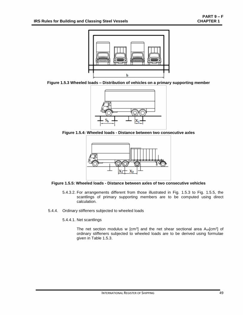
PART 9 – F IRS Rules for Building and Classing Steel Vessels CHAPTER 1
INTERNATIONAL REGISTER OF SHIPPING 49
Figure 1.5.3 Wheeled loads – Distribution of vehicles on a primary supporting member
Figure 1.5.4: Wheeled loads - Distance between two consecutive axles
Figure 1.5.5: Wheeled loads - Distance between axles of two consecutive vehicles
5.4.3.2. For arrangements different from those illustrated in Fig. 1.5.3 to Fig. 1.5.5, the
scantlings of primary supporting members are to be computed using direct calculation.
5.4.4. Ordinary stiffeners subjected to wheeled loads
5.4.4.1. Net scantlings
The net section modulus w [cm3] and the net shear sectional area Ash[cm2] of ordinary stiffeners subjected to wheeled loads are to be derived using formulae given in Table 1.5.3.

PART 9-F CHAPTER 1 IRS Rules for Building and Classing Steel Vessels
50 INTERNATIONAL REGISTER OF SHIPPING
Table 1.5.3: Net scantlings of ordinary stiffeners subjected to wheeled loads
w [cm3] Ash
[cm2]
𝐿 ≥ 40𝑚
𝑤 =167. 𝑘
225 − 𝜎1∙ 𝛼𝑊 ∙ 𝐾𝑠 ∙ 𝐹 ∙ ℓ
𝐴𝑠ℎ = 0.088 ∙ 𝑘 ∙ 𝛼𝑊 ∙ 𝐾𝑇 ∙ 𝐹
𝐿 < 40𝑚
𝑤 = 0.74 ∙ 𝑘 ∙ 𝛼𝑤 ∙ 𝐾𝑠 ∙ 𝐹 ∙ ℓ 𝑤 = 0.74 ∙ 𝑘 ∙ 𝛼𝑤𝐾𝑠 ∙ 𝐹 ∙ ℓ
αW = coefficient taking into account the number of wheels and wheels per axle considered as acting on the stiffener, defined in Table 2.8
KS, KT = coefficient taking into account the number of axles considered as acting on the stiffener, defined in Table 2.9.
Table 1.5.4: Wheeled loads - Coefficients αW
Configuration αW
Single wheel
1
Double wheels
2 ∙ (1 −𝑦
𝑠)
Triple wheels
3 − 2 ∙𝑦
𝑠
y= distance [m] from the external wheel of a group of wheels to the stiffener under consideration, to be taken equal to the distance from the external wheel to the centre of the group of wheels

PART 9 – F IRS Rules for Building and Classing Steel Vessels CHAPTER 1
INTERNATIONAL REGISTER OF SHIPPING 51
Table 1.5.5: Wheeled loads - Coefficients KS and KT
Coefficients
Single axle
Double axles
KS 1 -if 𝑑 < 2 ∙ ℓ 3⁄ 43
18−
7 ∙ 𝑑
4 ∙ ℓ−
𝑑2
8 ∙ ℓ2+
9 ∙ 𝑑3
16 ∙ ℓ3
-if 𝑑 ≥ 2 ∙ ℓ 3⁄
9
4−
3 ∙ 𝑑
8 ∙ ℓ−
3 ∙ 𝑑2
2 ∙ ℓ2
KT 1 2 − 0.5 ∙
𝑑
ℓ− 1.5 ∙
𝑑2
ℓ2+
𝑑3
ℓ3
d = distance [m] between two axles (see Fig.1.5.2)
Table 1.5.6: Net scantlings of primary supporting members
Item w [cm3] Ash [cm2]
Transverse primary supporting members
w = 0,58⋅k⋅𝑤 = 0.58 ∙ 𝑘 ∙ 𝛽𝑏 ∙ 𝑝 ∙
𝑠 ∙ ℓ2
𝐴𝑠ℎ = 0.045 ∙ 𝑘 ∙ 𝛽𝑠 ∙ 𝑝 ∙ 𝑠 ∙ ℓ
Deck girders 𝑤 =
125∙𝑘
214−𝜎1∙ 𝛽𝑏 ∙ 𝑝 ∙ 𝑆 ∙ ℓ2
𝐴𝑠ℎ = 0.045 ∙ 𝑘 ∙ 𝛽𝑠 ∙ 𝑝 ∙ 𝑆 ∙ ℓ
Double bottom girders 𝑤 =
125 ∙ 𝑘
197 − 𝜎1
∙ 𝛽𝑏 ∙ 𝑝 ∙ 𝑆 ∙ ℓ2 𝐴𝑠ℎ = 0.056 ∙ 𝑘 ∙ 𝛽𝑠 ∙ 𝑝 ∙ 𝑆 ∙ ℓ
Vertical primary supporting members
𝑤 =125 ∙ 𝑘
214 − 𝜎𝐴
∙ 𝜆𝑏 ∙ 𝛽𝑏 ∙ 𝑝 ∙ 𝑆 ∙ ℓ2 𝐴𝑠ℎ = 0.045 ∙ 𝑘 ∙ 𝜆𝑠 ∙ 𝑝 ∙ 𝑆 ∙ ℓ
p = design load [kN/m2]: p = peq
σA = axial stress, to be obtained [N/mm2] from the following formula:
= 10 ∙𝐹𝐴
𝐴
FA = axial load transmitted to the vertical primary supporting members by the structures
above
A = net sectional area [cm2] of the vertical primary supporting members with attached plating of width bP

PART 9-F CHAPTER 1 IRS Rules for Building and Classing Steel Vessels
52 INTERNATIONAL REGISTER OF SHIPPING
SECTION 6 PASSENGER VESSELS Contents
Contents
6.1. Symbols ............................................................................................................................................ 53
6.2. General ............................................................................................................................................. 53
6.3. Vessel arrangement ......................................................................................................................... 54
6.4. Fire protection, detection and extinguishing .................................................................................... 56
6.5. Electrical installations ....................................................................................................................... 58
6.6. Buoyancy and stability ..................................................................................................................... 62
6.7. Design loads ..................................................................................................................................... 69
6.8. Hull girder strength ........................................................................................................................... 72
6.9. Scantlings ......................................................................................................................................... 73

PART 9 – F IRS Rules for Building and Classing Steel Vessels CHAPTER 1
INTERNATIONAL REGISTER OF SHIPPING 53
6.1. Symbols
L = Rule length [m] defined in Part 9C Chapter 1, Section 1, [1.2.1]; B = Breadth [m] defined in Part 9C Chapter 1, Section 1, [1.2.1]; D = Depth [m] defined in Part 9C Chapter 1, Section 1, [1.2.1]; T = Draught [m] defined in Part 9C Chapter 1, Section 1, [1.2.1]; LWL= Length of the hull [m] measured at the maximum draught; Δ = Displacement of the laden vessel [t]; v = Maximum speed of the vessel in relation to the water [m/s]; KG = Height [m] of the centre of gravity above base line; CB = Block coefficient; S = Spacing [m] of primary supporting members; n = Navigation coefficient defined in Part 1.
= 0.85. 𝐻 H = Significant wave height [m]; σ1= Hull girder normal stress [N/mm2]; z = Z co-ordinate [m] of the calculation point.
6.2. General
6.2.1. Application 6.2.1.1. Vessels fulfilling the requirements of this Section qualify for the assignment of the
type and service Notation Passenger vessel, as defined in Part 9 C Chapter 2 Section 2, [2.5.1.1.]
6.2.1.2. Vessels dealt herein this Section are to meet the requirements stated in Part 9 A,B,C,D,E, as applicable, and also with the requirements of this Section, which are specific to passenger vessels.
6.2.1.3. All the varied requirements of these Rules are to be applied for safety of passengers and crew as per Table 1.6.1. Where available, statutory Regulations in the operating area of the vessel (e.g. Rhine Rules, European directive) are to be given priority over these requirements.
6.2.2. Definitions
6.2.2.1. Day trip vessel This passenger vessel does not have an overnight passenger cabins.
6.2.2.2. Cabin vessel This passenger vessel has overnight passenger cabins.
Table 1.6.1: Requirements applicable for safety of passengers and crew
Item Applicable requirements
Subdivision, transverse bulkheads 6.3.1
Passenger rooms and areas 6.3.2
Propulsion system 6.3.3
Fire protection, detection and extinguishing
6.4
Electrical installations 6.5

PART 9-F CHAPTER 1 IRS Rules for Building and Classing Steel Vessels
54 INTERNATIONAL REGISTER OF SHIPPING
6.3. Vessel arrangement
6.3.1. Subdivision, transverse bulkheads
6.3.1.1. Besides the bulkheads called for in Part9 C Chapter 5 Section 4. The vessel is to be further sub-divided into watertight transverse bulkheads such that the requirements of stability and reserve buoyancy are met. All these bulkheads are to be extended upwards to the bulkhead deck. The stepping of bulkheads is allowed only if they are located outside the penetration depths mentioned in [6.6.3.3.]
6.3.1.2. First compartment aft of the collision bulkhead may be shorter than the length of damage stipulated in [6.6.3.3], provided the total length of the two foremost compartments measured in the plane of maximum draught is not less than the value obtained below. Distance of the collision bulkhead from the forward perpendicular shall be between
0.04 ⋅ LWL and (0.04 ⋅ LWL+ 2) [m].
6.3.1.3. Passenger spaces are to be separated by watertight bulkheads from machinery, cargo and boiler spaces. Doors are not allowed on the separation bulkheads between machinery and passenger spaces. The number of openings in watertight bulkheads shall be as small as possible and also suitable for the construction and vessel’s operation.
6.3.1.4. Normally, bulkhead doors which are in the OPEN position shall be locally operable from both sides of the bulkhead, and could be closed from an accessible location above the bulkhead deck. Besides that, they shall meet the conditions given below:
The closing time is not to be less than 20s and not more than 60s.
At remote control position, the indicator lights are to be mounted which shows whether the door is open or closed.
During closing operation, a local audible alarm shall ring automatically.
The door drive and signaling systems shall also be independently operable of the vessel’s mains. Only outside the passenger area, bulkhead doors without remote control are permitted and they are to be kept closed all the time and may only be opened to allow passageway for a very short time. Bulkhead doors and their systems shall be situated outside the penetration depth specified in [6.6.3.3]. Open piping systems and ventilation ducts are to be routed in such a manner that no flooding can take place under any considered damaged condition. Pipelines situated outside the penetration depth stipulated in [6.6.3.3] and more than 0.5 m above the base line are to be regarded as undamaged. Watertight bulkhead openings below the margin line are to be arranged. Note: Margin line is an imaginary line drawn on the side plating at not less than 10 cm below the bulkhead deck and the lowest non-watertight point of the vessel's side. If there is no such bulkhead deck, a line drawn at not less than 10 cm below the lowest line up to which the outer plating is water-tight shall be used.
PART 9 – F IRS Rules for Building and Classing Steel Vessels CHAPTER 1
INTERNATIONAL REGISTER OF SHIPPING 55
6.3.2. Passenger rooms and areas 6.3.2.1. Means of escape
Minimum two widely separated and easily accessible means of escape shall be provided in spaces or group of spaces onboard vessel for 30 or more passengers or are equipped as such or which have beds for 12 or more passengers. On day trip vessels, one of the above mentioned means of escape may be substituted by two emergency exits. For spaces lying below the freeboard deck, one of means of escape may be a watertight door that leads directly to the adjacent watertight compartment from where reaching the uppermost deck is easy. The second means of escape shall be such that it leads directly to a safe area above the bulkhead deck or open deck. These pre-requisites do not apply to single cabins. It is of utmost significance that all the means of escape are arranged in a practical way and have a clear width of 0.8 m and a clear height of 2 m at least. The width of doors leading to cabins may be decreased to 0.7 m. Means of escape from the spaces and group of spaces provided for 80 or more passengers are to be arranged, having a clear width of at least 0.01m/passenger. This is also applicable to doors within the escape route. The doors shall always open in the same direction as means of escape and shall also be clearly marked.
6.3.2.2. Doors of passenger rooms Observing compliance with the requirements given below is essential for doors of passenger rooms: a. Except the doors leading to connecting corridors, all the doors of passenger
rooms shall open outwards or shall be the sliding doors. b. Cabin doors shall be so made that they can also be unlocked from outside at
any time.
6.3.2.3. Stairs Observing compliance with the requirements given below is essential for the stairs and their landings in the passenger areas: a. They shall be made as per some recognized standards. b. Their clear width shall be at least 0.80 m or, and if they lead to connecting
corridors or areas used by 80 or more passengers, at least 0.01 m per passenger.
c. Their clear width shall be at least 100 m, when provide the only means of access to a room intended for passengers.
d. Stairs shall not be in the damage area, unless there is at least one staircase on each side of the vessel in the same zone.
6.3.2.4. Escape routes Escape routes shall meet the requirements given below:

PART 9-F CHAPTER 1 IRS Rules for Building and Classing Steel Vessels
56 INTERNATIONAL REGISTER OF SHIPPING
a. All the exits, stairways and emergency exits shall be so arranged and kept ready that, in the event of fire in any given area, the escape for passengers may be safely evacuated.
b. The escape routes shall use the shortest route to evacuation areas. c. Escape routes shall not pass through engine rooms or galleys. d. At any point along the escape routes, installation of any rungs, ladders shall be
avoided. e. Doors to escape routes shall not reduce the minimum width of the escape
route. f. Escape routes and emergency exits shall be clearly signaled and the signs
shall be lit by the emergency lighting system.
6.3.3. Propulsion system
6.3.3.1. Besides the main propulsion system, vessels shall be equipped with another independent propulsion system that during breakdown affecting the main propulsion system can render the vessel with the ability to continue steerageway under its own power.
6.3.3.2. The other independent propulsion system shall be located in a separate engine
room. However, if engine rooms housing the two independent propulsion systems have common partitions, these shall be built in compliance with ****
6.4. Fire protection, detection and extinguishing
6.4.1. Documents for review/approval
The following drawings and documents are to be submitted, where applicable, for review/approval:
Fire division/insulation plan showing designation of each space, including information on applied materials and constructions.
Escape route plan;
Ventilation plan;
Sprinkler system.
6.4.2. Fire protection in accommodation areas
6.4.2.1. General It is pre-requisite that all insulation materials, linings, bulkheads, ceilings and draught stops shall be of approved non-combustible material. Also, all the primary deck coverings and surface materials shall be of approved fire-retardant type.
6.4.2.2. Integrity of bulkheads and decks Bulkheads to corridors shall be of approved type B-15 and those between cabins shall be of approved type B-0. Where sprinkler system is fitted, bulkheads to corridors may be reduced to approved type B-0. Bulkheads to corridors shall extend from deck to deck unless a continuous B-class ceiling is fitted on both sides of it and in that case the corridor bulkhead may terminate at the continuous ceiling.
PART 9 – F IRS Rules for Building and Classing Steel Vessels CHAPTER 1
INTERNATIONAL REGISTER OF SHIPPING 57
Stairways are to be constructed of steel frame or other non-combustible material. Stairways connecting more than two decks are to be enclosed by class B bulkheads. However, those stairways which connect only two decks need to be enclosed at one deck level at least by class B bulkheads. The fire resistance of doors shall be same fire-class as that of the bulkheads in which they are fitted. Where class A and B divisions are penetrated for the passage of cables, trunks, pipes, ducts etc. or for the fitting of ventilation terminals, lighting fixtures and similar devices, arrangements shall be made to ascertain that the fire resistance is not compromised.
6.4.2.3. Internal subdivision Class A divisions shall sub-divide the vessel into sections of not more than 40 m in length. The doors shall be of self-closing type or capable of remote release from the Fire Control Station and individually from both sides of the door. Status of each fire door (open/closed position) shall be indicated in the Fire Control Station. Class A divisions shall separate galleys and control stations from adjacent spaces and machinery spaces from accommodation areas. Doors fitted therein shall have same fire resistance and be self-closing and reasonably gastight. Air spaces behind paneling, ceilings, or linings shall be divided by close-fitting draught stops spaced not more than 14 m apart. In the vertical direction, at each deck level, such enclosed air spaces, including those behind linings of stairways, trunks, etc., shall be closed.
6.4.2.4. Means of escape Means of escape required by [6.3.2.1] shall give direct access to a stairway from where the embarkation deck or the open deck can be reached. Stairways shall have a clear width (i.e. between bulkheads and/or hand-rails) of at least 0.80 m. Emergency exits shall have dimension of not less than (0.70 ×0.70) m2 or diameter of at least 0.7 m and shall open in the direction of escape and be marked on both sides.
6.4.2.5. Ventilation system Non-combustible material shall be used in making of all parts of the ventilation system, except the short ducts applied at the end of the ventilation device. Those may be made of material which has low-flame spread characteristics (see Fire Test Procedure Code, Annex 1, Part 5, adopted by IMO by Resolution MSC. 61 (67).). Ventilation ducts are to be subdivided by approved fire dampers analogously as per the requirements of [6.4.2.3] .Penetrations through stairway boundaries are to be provided with approved fire dampers. Fire dampers shall be designed to locally operable from both sides of the fire division.

PART 9-F CHAPTER 1 IRS Rules for Building and Classing Steel Vessels
58 INTERNATIONAL REGISTER OF SHIPPING
6.4.3. General water fire extinguishing system
6.4.3.1. Passenger vessels more than 40m LWL and passenger vessels with cabins for passengers more than 25m LWL are required to be in compliance with the additional requirements stipulated from [6.4.3.2] to [6.4.3.5.]
6.4.3.2. Arrangements to project at least two jets of water simultaneously on any part of the vessel from two different hydrants shall be made. using a single length of hose not more than 20 m long and the length of throw shall be at least 12 m with a nozzle diameter of 12 mm.
6.4.3.3. The fire pump shall have a minimum capacity of 20 m3/h. 6.4.3.4. If fire pump is located in the engine room, another power-driven fire pump shall be
provided outside that room. The pump drive shall be independent of the engine room, and the pump capacity shall be sufficient to meet the requirements of 6.4.3.2 and 6.4.3.3. Within the engine room, connections in the piping system shall be such that they can be shut off from outside, near the entry point of the engine room. When a permanently installed pump is available in the engine room, a portable pump may be accepted.
6.4.3.5. In the hose boxes of both aft and fore ship, two fire hoses with dual-purpose nozzles are to be located. More fire hoses may be needed depending on the size and structural arrangements of the vessel.
6.4.4. Portable fire extinguisher
6.4.4.1. One additional fire extinguisher is to be provided for:
Each group of 10 cabins, or part thereof.
Each unit of 120 m2, or part thereof, of the gross floor area of dining rooms, recreation spaces and day rooms.
6.4.4.2. Depending on their size and contents, galleys and shops shall be provided with additional fire extinguishers. Their location shall be such that in event of a fire, at least one is accessible in the closest vicinity position.
6.4.5. Fixed fire extinguishing systems A fixed fire extinguishing system shall be provided in the machinery spaces housing internal combustion engines that are used for propulsion and in oil fired boilers and shall have compliance with Part D Chapter 15 Section 2, [2.6]. The installed automatic pressure water spraying systems shall always be ready for operation for the passenger when passengers are on board. Crew shall not need to actuate any system and take any additional measures to bring them into operation.
6.5. Electrical installations
6.5.1. General 6.5.1.1. Application
Day trip vessels and cabin vessels (LWL ≥ 25 m) are required to be in compliance with the requirements given here under in addition to the requirements given in Part 9 E.

PART 9 – F IRS Rules for Building and Classing Steel Vessels CHAPTER 1
INTERNATIONAL REGISTER OF SHIPPING 59
These rules may be relaxed for ferries and day passenger vessels.
6.5.2. Generator plant Minimum two independent main generator plants are to be provided that can supply power to the electrical equipments. The prime mover system and the generator output shall be such that if any generator set is taken out of service or fails, the rest is adequate to meet the requirements of running service and manoeuvring.
6.5.3. Emergency power supply and emergency lighting 6.5.3.1. General
An emergency source of power that functions independently and does not depend on the main power supply is to be provided. This source shall be capable of feeding the electrical systems and consumers as that is vital to the safety of passengers and crew. Although the feeding time of such a system varies depending on the purpose of the vessel but that should be agreed with the national Authority, and shall not be less than half an hour. The power supply to the following systems is especially relevant to the safety of passengers and crew:
Navigation and signalling lights;
Radio installations;
Alarm systems for vessel’s safety;
Sound devices such as tyfon;
Public address system (general alarm);
Telecommunication systems vital to safety and vessel’s operation;
Emergency lighting;
Emergency searchlights;
Fire detection system;
Sprinkler systems and other safety installations.
6.5.3.2. Emergency source of electrical power a. A generator set whose fuel supply and cooling system works independent of
the main engine, which starts functioning automatically when network failure occurs and requires just about 30 seconds to automatically take over the power supply.
b. A storage battery which automatically resumes the power supply when network failure occurs and is capable of supplying power to the above mentioned consumers for the required time period without recharging and without an unacceptable voltage drop.
6.5.3.3. Installation
The installation of the emergency generator sets, emergency storage batteries and the relevant switchgear is to be done outside the main generator room, machinery space and machinery casings. They are to be kept distinct from these spaces using fire retardant and watertight bulkheads so that the emergency power supply is not impaired in the event of a fire or some other sudden mishap in the machinery space. The emergency power supply shall be fully serviceable with a permanent list of 22.5° and/or a trim of 10°. Arrangements to facilitate periodical testing of all items of equipment serving the emergency power supply system including the automatic switchgear and starting

PART 9-F CHAPTER 1 IRS Rules for Building and Classing Steel Vessels
60 INTERNATIONAL REGISTER OF SHIPPING
equipment is to be provided. There shall be no hindrance to such testing by other aspects of the vessel’s operation.
6.5.4. Alarm and communication systems The requisites of the Part 9 E Chapter 4. are to be observed. 6.5.4.1. Fire detection and alarm system
The monitoring of all day rooms accessible to passengers and crew as well as galleys and machinery spaces is to be done by a type tested automatic fire detection and alarm system. a. The grouping of detectors are to be done into separate sections, each of which
shall not comprise more than one watertight division and one main fire zone or not more than two vertically adjacent decks. If the fire detection system is designed for remote and individual identification of detectors, several decks in one main fire zone respectively one watertight division may be monitored by the same detector loop. The detector loop shall be so made, that if damaged (wire break, short circuit, etc.) only a part of it becomes faulty. Smoke detectors shall be used in stairways, passageways and escape routes. In the accommodation areas, heat detectors shall be used in all the cabins. Additionally, flame detectors shall be used.
b. The outbreak of a fire and the area concerned are to be automatically signalled to a permanently manned station.
c. The requirements of preceding a) and b) are deemed to be met especially for spaces protected by an automatic pressure water-spraying system designed as per Part 9 D Chapter 15.
d. In addition to the automatic systems, manually operated call points are to be provided:
In day rooms, saloons and dining rooms;
In passageways and enclosed stairways;
At lifts;
In machinery spaces, galleys and spaces prone to fire hazard.
There shall be minimum one call point in every watertight compartment and such manually operated call points shall be not be spaced more than 10 m apart.
e. The alarm set off by a manual call point shall be heard only in the rooms of the vessel's officers and crew. They shall be capable of cancelling them. Moreover, unintended operation of manual call points is to be prevented.
6.5.4.2. Passenger alarm system Passenger vessels with cabins shall be equipped with a passenger alarm system that is capable of being actuated from the wheelhouse and a permanently manned station. The alarm shall be heard clearly in all rooms accessible to passengers. The unintended operation of alarm actuator has to be safeguarded.

PART 9 – F IRS Rules for Building and Classing Steel Vessels CHAPTER 1
INTERNATIONAL REGISTER OF SHIPPING 61
6.5.4.3. Crew alarm system Passenger vessels with passenger cabins shall be equipped with a crew alarm system in each such cabin and also in alleyways, lifts and stairwells. The distance to the next actuator shall not be more than 10 m, but at least one actuator is to be there in every watertight compartment; in crew mess rooms, engine rooms, kitchens and similar rooms prone to fire hazard.
6.5.4.4. Engineer’s alarm An engineer's alarm is to be provided that enables summoning the machinery personnel in their quarters right from the engine room, if that is very important considering the arrangement of the machinery space with respect to the engineers' accommodation.
6.5.5. Intercommunications 6.5.5.1. Inter-communications from the bridge
Where direct means of communication do not exist between the bridge and the:
Service spaces;
Crew's day rooms;
Engine room (control platform);
Foreship and aftship,
A suitable intercommunications system is to be provided. The general telephone system can be approved for this purpose, provided that the bridge/ engine link is on high priority and that existing calls between other parties on this line can be interrupted. Where telephone system is used, the engineer's alarm may be dispensed with, provided that two-way communication is possible between machinery space and engineers' accommodation.
6.5.5.2. Public address systems Vessels with a length LWL of 40 m and over and those intended for carrying more than 75 passengers shall be equipped with loudspeakers that can be heard by all the passengers.
6.5.6. Fire door and watertight door closure indicators The permanently manned safety station or door release panel on the bridge shall be equipped with indicators that signal the opening and closing of fire doors or watertight doors.
6.5.7. Lighting systems 6.5.7.1. Construction and extent of the main lighting system
The main lighting system supplied by the main source of electrical power and that illuminates all parts of the ship shall be normally accessible to the passengers and crew. This system is to be installed in compliance with Part 9 E Chapter 3.
6.5.7.2. Construction and extent of the emergency lighting system a. Construction
PART 9-F CHAPTER 1 IRS Rules for Building and Classing Steel Vessels
62 INTERNATIONAL REGISTER OF SHIPPING
The extent, to which an emergency lighting system is installed, shall conform to b). The power supply and the duration of the supply shall be in compliance with 6.6.5.3. If feasible, the emergency lighting system shall be installed where it will not be rendered unserviceable by fire or other mishap in rooms in which the main electrical power source, any associated transformers, main switchboard and main lighting distribution panel are installed. The emergency lighting system shall start automatically following a failure of the main power supply. Local switches are provided only where switching off the emergency lighting is required (as in the wheelhouse). Emergency lights shall also be marked for their easy identification.
b. Extent In the areas given below, adequate emergency lighting shall be provided:
Positions at which collective life-saving appliances are stored and where they are normally prepared for use.
Connecting passageways, escapes, exits, lifts and stairways in the accommodation area;
Marking indicating escapes and exits;
Machinery spaces and their exits;
Space where emergency power source is located;
Wheelhouse;
Locations of fire pumps and fire extinguishers;
Rooms in which passengers and crew assemble in an emergency.
c. If vessel is divided into main fire zones, at least two circuits are to be provided for lighting of each zone, and these shall have their own power supply line. One circuit shall be supplied from the emergency power source. The supply lines are to be so stationed that, if fire spreads in one main fire zone, the lighting in the other is, as far as practicable, maintained.
6.5.7.3. Final sub-circuits In significant spaces specified below, lighting shall be supplied by at least two different circuits:
Stairways leading to the boat deck, public spaces and day rooms for passengers and crew;
Passageways;
Large galleys.
Lamps are to be so arranged that lighting is adequate even if the circuits fails.
6.6. Buoyancy and stability
6.6.1. General General requirements are to be in compliance with Part 9 C Chapter 8. Stability calculations have to be based on ship-specific light ship data, i.e. to be determined by performing an inclining experiment.
PART 9 – F IRS Rules for Building and Classing Steel Vessels CHAPTER 1
INTERNATIONAL REGISTER OF SHIPPING 63
6.6.2. Intact stability
6.6.2.1. General
Appropriate proof of intact stability of the vessel shall be furnished and all calculations shall be done free to trim and sinkage.
6.6.2.2. Standard loading conditions For the following standard load conditions, intact stability shall be proven:
a. At beginning of the voyage:
100% passengers, with provisions, 98% fuel and fresh water, 10% waste water b. During the voyage:
100 % passengers, with provisions, 50 % fuel and fresh water, 50 % waste water
c. At end of the voyage: 100 % passengers, with provisions, 10 % fuel and fresh water, 98 % waste water
d. Unladen vessel: No passengers, 10 % fuel and fresh water, no waste water.
For all standard load conditions, the ballast tanks shall be considered as either empty or full as per normal operational conditions. As a pre-requisite for changing the ballast while under way, the requirement of 6.6.2.3, item d), shall be proved for the load condition given below: – 100% passengers, 50% fuel and fresh water, 50% waste water, all other liquid (including ballast) tanks are considered filled to 50%.
6.6.2.3. Intact stability criteria The proof of adequate intact stability with help of calculations shall be produced using the intact stability criteria given below, for the standard loading conditions mentioned in 6.6.2.2, items a) to c): a. The maximum righting lever arm hmax shall occur at list angle of Φmax ≥(Φmom+
3°) and not less than 0.20 m. However, in case Φf< Φmax the righting lever arm at the down-flooding angle Φf shall not be less than 0.20 m.
b. The downflooding angle Φf shall not be less than Φmom+ 3°.
c. The area A under the curve of the righting lever arm shall, depending on the position of Φf and Φmax, reach the values given in Table 1.6.3, where: Φ = List angle; Φf = List angle, at which openings in the hull, in the superstructure or deck houses which cannot be closed so as to make weathertight, when submerge. Φmax= List angle at which the maximum righting lever arm occurs. Φmom= Maximum list angle defined under item e). A = Area beneath the curve of the righting lever arms.
d. The metacentric height at the start, GM0, corrected by the effect of the free surfaces in liquid tanks, shall not be less than 0.15 m.
e. In the following two cases, the list angle Φmom shall not be in excess of the value of 12°:

PART 9-F CHAPTER 1 IRS Rules for Building and Classing Steel Vessels
64 INTERNATIONAL REGISTER OF SHIPPING
In application of the heeling moment due to crowding of passengers at one side and wind as per 6.6.2.4 and 6.6.2.5.
In application of the heeling moment due to crowding of passengers at one side and turning as per 6.6.2.4 and 6.6.2.6.
f. For a heeling moment resulting from moments due to passengers crowding at one side, wind and turning as per 6.6.2.4, 6.6.2.5 and 6.6.2.6, the residual freeboard shall not be less than 200 mm.
g. For vessels with windows or other openings in the hull and that is located below the bulkhead decks but not closed watertight, the residual safety clearance shall be 100 mm at least on the application of the heeling moments resulting from item e) above.
6.6.2.4. Moment due to crowding of passengers
The heeling moment MP [kNm] due to one-sided accumulation of persons is to be calculated as per the following formula:
𝑀𝑃 = 𝑔. 𝑃. 𝑦 = ∑ 𝑃𝑖 . 𝑦𝑖
P = Total weight of persons on board [t]. It is calculated by adding up the maximum permitted number of passengers and shipboard personnel along with crew under normal operating conditions, assuming an average weight of 0.075 t per person. y = Lateral distance [m] of center of gravity of total weight of persons P from center line; g = Acceleration of gravity (g = 9.81 m/s2); Pi = Weight of persons accumulated on area Ai, [t];
= 0.075 ⋅ 𝑛𝑖 ⋅ 𝐴𝑖
Ai = Area [m2] occupied by persons; ni = Number of persons per square meter. For deck areas with movable furniture and free deck areas: 𝑛𝑖 = 3.75. For deck areas with benches (i.e. fixed furniture), ni shall be calculated by assuming an area of 0.50 m in width and 0.75 m in seat depth per person. yi = Lateral distance [m] of geometrical center of area Ai from center line. The calculation shall be done for accumulation of persons both to starboard and to port. The distribution of persons shall correspond to the most unfavorable one from stability point of view. While computing the person moment, cabins shall be assumed unoccupied. For the calculation of the loading cases, the centre of gravity of a person should be taken 1 m above the lowest point of the deck at 1/2 LWL, and deck curvature can be ignored and weight of 0.075 t per person is assumed. If the values given below are used, a detailed calculation of deck areas which are occupied by persons may be dispensed with. – 𝑦 = 𝐵/2 [m]
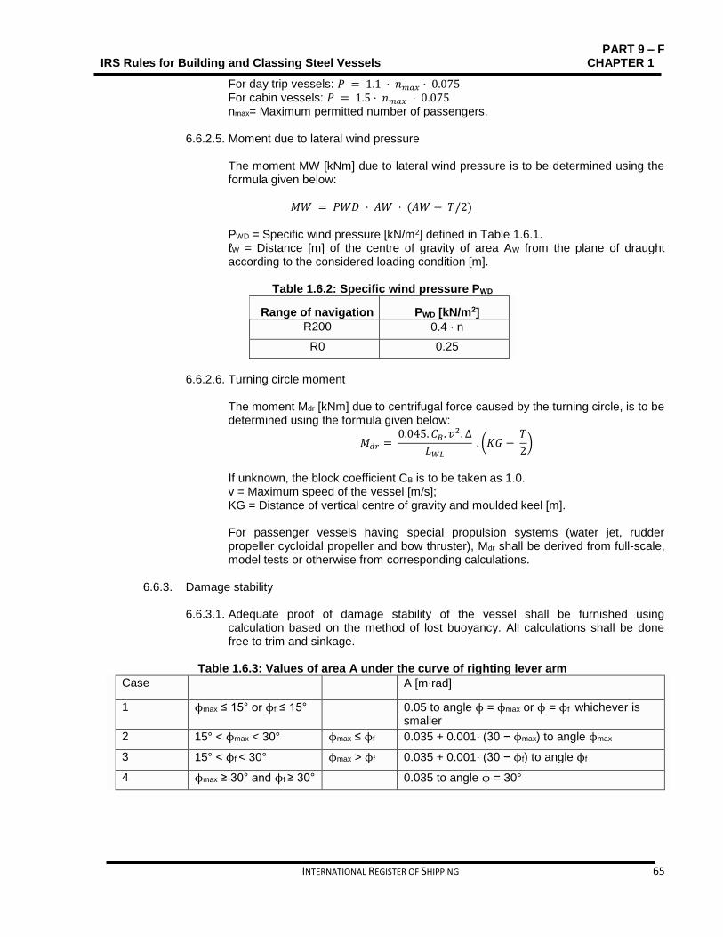
PART 9 – F IRS Rules for Building and Classing Steel Vessels CHAPTER 1
INTERNATIONAL REGISTER OF SHIPPING 65
For day trip vessels: 𝑃 = 1.1 ⋅ 𝑛𝑚𝑎𝑥 ⋅ 0.075 For cabin vessels: 𝑃 = 1.5 ⋅ 𝑛𝑚𝑎𝑥 ⋅ 0.075 nmax= Maximum permitted number of passengers.
6.6.2.5. Moment due to lateral wind pressure The moment MW [kNm] due to lateral wind pressure is to be determined using the formula given below:
𝑀𝑊 = 𝑃𝑊𝐷 ⋅ 𝐴𝑊 ⋅ (𝐴𝑊 + 𝑇/2)
PWD = Specific wind pressure [kN/m2] defined in Table 1.6.1. ℓW = Distance [m] of the centre of gravity of area AW from the plane of draught according to the considered loading condition [m].
Table 1.6.2: Specific wind pressure PWD
Range of navigation PWD [kN/m2]
R200 0.4 ⋅ n
R0 0.25
6.6.2.6. Turning circle moment
The moment Mdr [kNm] due to centrifugal force caused by the turning circle, is to be determined using the formula given below:
𝑀𝑑𝑟 = 0.045. 𝐶𝐵 . 𝑣2. ∆
𝐿𝑊𝐿
. (𝐾𝐺 − 𝑇
2)
If unknown, the block coefficient CB is to be taken as 1.0. v = Maximum speed of the vessel [m/s]; KG = Distance of vertical centre of gravity and moulded keel [m]. For passenger vessels having special propulsion systems (water jet, rudder propeller cycloidal propeller and bow thruster), Mdr shall be derived from full-scale, model tests or otherwise from corresponding calculations.
6.6.3. Damage stability 6.6.3.1. Adequate proof of damage stability of the vessel shall be furnished using
calculation based on the method of lost buoyancy. All calculations shall be done free to trim and sinkage.
Table 1.6.3: Values of area A under the curve of righting lever arm
Case A [m⋅rad]
1 ϕmax ≤ 15° or ϕf ≤ 15° 0.05 to angle ϕ = ϕmax or ϕ = ϕf whichever is smaller
2 15° < ϕmax < 30° ϕmax ≤ ϕf 0.035 + 0.001⋅ (30 − ϕmax) to angle ϕmax
3 15° < ϕf < 30° ϕmax > ϕf 0.035 + 0.001⋅ (30 − ϕf) to angle ϕf
4 ϕmax ≥ 30° and ϕf ≥ 30° 0.035 to angle ϕ = 30°

PART 9-F CHAPTER 1 IRS Rules for Building and Classing Steel Vessels
66 INTERNATIONAL REGISTER OF SHIPPING
Table 1.6.4: Extent of damage [m]
Dimension of the damage 1-compartment status 2-compartment status
Side damage longitudinal A 0.1⋅ LWL ≥ 4 0.05⋅ LWL ≥ 2.25
transverse b B/5 0.59
vertical h from vessel bottom to top without delimitation
Bottom damage longitudinal A 0.1⋅ LWL ≥ 4 0.05⋅ LWL ≥ 2.25
transverse b B/5
vertical h 0.59; pipework shall be deemed intact 1
1 Where a pipework system has no open outlet in a compartment, the pipework shall be regarded as intact in the event of this compartment being damaged, if it runs within the safe area and is more than 0.50 m off the bottom of the vessel.
6.6.3.2. Buoyancy of the vessel during flooding shall be proven for the standard loading
conditions given in 6.6.2.2. On that basis, mathematical proof of stability shall be determined for the three (3) intermediate stages of flooding (25%, 50% and 75% of flood build-up) and for the final stage of flooding.
6.6.3.3. Assumptions In incidence of flooding, assumptions regarding the extent of damage as given in Table 1.6.4 shall be taken into account.
a. For 1-compartment status, the bulkheads can be assumed to be intact when
the distance between two adjacent bulkheads is greater than the dam-age length. Longitudinal bulkheads at a distance less than B/3 measured rectangular to centre line from the shell plating at the maximum draught plane shall not be taken into account for calculation purposes.
b. For 2-compartment status, it is assumed that each bulkhead within the extent of damage will be damaged. This implies that the position of the bulkheads shall be selected to ascertain that the passenger vessel remains buoyant after flooding of two or more adjacent compartments in the longitudinal direction.
c. The lowest point of every non-watertight opening (e.g. windows, doors, access hatchways) shall lie at least 0.10 m above the damage waterline. In the final stage of flooding, the bulkhead deck shall not be submerged.
d. Assumed permeability is 95% and if it is proven by calculation that the average
permeability of some compartment is less than 95%, the calculated value can be used in place of that. The values given in Table 1.6.5 shall be adopted and values lesser than those are not acceptable.
e. During the calculations, this shall be taken into account that the damage of a smaller dimension than specified above produces more detrimental effects with respect to listing or loss of metacentric height.
6.6.3.4. Damage stability criteria
a. The criteria’s given below shall be met for all intermediate stages of flooding
referred to in 6.3.2:
The angle of heel Φ at the equilibrium position of the intermediate stage in question shall not go beyond 15°.

PART 9 – F IRS Rules for Building and Classing Steel Vessels CHAPTER 1
INTERNATIONAL REGISTER OF SHIPPING 67
Beyond the inclination in the equilibrium position of the intermediate stage in question, the positive part of the righting lever arm curve shall display a righting lever arm value of GZ ≥0.02 m before the first unprotected opening
becomes immersed or an angle of heel ϕ of 25° is attained Non-watertight openings shall not be submerged before inclination in the
equilibrium position of the intermediate stage in question has been attained.
b. During final stage of flooding, the criteria given below shall be met (see Fig.
1.6.1) taking into account the heeling moment due to passengers crowding as per 6.6.2.4:
The angle of heel ϕE shall not go beyond10°. Beyond the equilibrium position, the positive part of the righting lever arm
curve shall display a righting lever arm value of GZR ≥ 0.02 m with an area
A ≥ 0.0025 m ⋅ rad. These minimum values for stability shall be met until the immersion of the first unprotected opening or before reaching an angle
of heel ϕm ≤ 25°. Non-watertight openings shall not be submerged before the trimmed
position has been reached; if that happens before this point, the rooms offering access are deemed to be flooded for the purpose of damage stability calculation.
Table 1.6.5: Permeability values [%]
Spaces μ
Lounges 95
Engine and boiler rooms 85
Luggage and store rooms 75
Double bottoms, fuel bunkers and other tanks, depending on whether, according to their intended purpose, they are to be assumed to be full or empty for the vessel floating at the plane of maximum draught
0 or 95
6.6.3.5. Appropriate marking of the shut-off devices which shall be closed watertight is important. Instead, if cross-flood openings are provided to reduce asymmetrical flooding, they shall meet the conditions given below: a. They shall be self-activated. b. For cross-flooding calculation, IMO Resolution MSC.245 (83) shall be applied. c. They shall not be equipped with shut-off devices. d. The total time permitted for compensation shall not exceed 15 minutes.

PART 9-F CHAPTER 1 IRS Rules for Building and Classing Steel Vessels
68 INTERNATIONAL REGISTER OF SHIPPING
Fig. 1.6.1: Proof of damage stability (final stage of flooding)
6.6.4. Derogations for certain passenger vessels
6.6.4.1. As an alternative to proving adequate stability after damage as per 6.6.3,
passenger vessels with more than 25m length and authorized to carry up to 50 passengers maximum shall conform to the criteria given below: a. After symmetrical flooding, the immersion of the vessel shall not exceed the
margin line; and b. The metacentric height GM0 shall not be less than 0.10 m. The necessary residual buoyancy shall be assured through appropriate choice of material used for the construction of the hull or by means of highly cellular foam floats, solidly attached to the hull. For vessels with more than 15 m length, residual buoyancy can be ascertained by a combination of floats and subdivision conforming to the 1-compartment status as per 6.6.3.
6.6.4.2. By way of derogation from 6.6.3.3, passenger vessels with length not exceeding 45 m and authorized to carry maximum 250 passengers do not need to have 2-compartment status.
6.6.5. Safety clearance and freeboard 6.6.5.1. Safety clearance
The safety clearance shall equal to at least the sum of: a. The additional lateral immersion, which, measured on the outside plating, is
produced by the permissible angle of heel as per 6.6.2.3 e), and b. The residual safety clearance as per 6.6.2.3 g). For vessels without a bulkhead deck, the safety clearance shall be at least 500 mm.
6.6.5.2. Freeboard
The freeboard shall equate to at least the sum of:

PART 9 – F IRS Rules for Building and Classing Steel Vessels CHAPTER 1
INTERNATIONAL REGISTER OF SHIPPING 69
a. The additional lateral immersion, which, measured on the outside plating, is produced by the angle of heel as per 6.6.2.3 e), and
b. The residual freeboard as per 6.6.2.3 f). The freeboard shall be at least 300 mm.
6.6.5.3. The plane of maximum draught is to be set so as to ascertain conformation to the safety clearance as per 6.6.4.1, and the freeboard as per 6.6.4.2.
6.6.5.4. IRS may stipulate, for safety reasons, a greater safety clearance or a greater freeboard.
6.7. Design loads
6.7.1. Pressure on sides Following formulae is used to derive the design lateral pressure at any point of the hull sides: 𝑃𝐸 = 9.81. (𝑇 − 𝑧 + 0.6. 𝑛) for z ≤T
𝑃𝐸 = 𝑀𝐴𝑋(5.9. 𝑛; 3) + 𝑃𝑊𝐷 for z > T pWD= specific wind pressure [kN/m2] defined in Table 1.6.2.
6.7.2. Pressure on sides and bulkheads of deckhouses and super-structures Using the following formulae, the lateral pressure [in kN/m2] to be used for the determination of scantlings of structure of sides and bulkheads of deckhouses and super-structures is to be obtained:
𝑝 = 2 + 𝑝𝑊𝐷
pWD= is the specific wind pressure [kN/m2] defined in Table 1.6.2.
6.7.3. Pressure on decks It is the Designer who defines the pressure due to load carried on decks and, in general, it may not be taken less than the values given in Table 1.6.6.
6.7.4. Loads due to list and wind action 6.7.4.1. General
Following are the loads inducing the racking in vessel superstructures above deck 1 (see Fig. 1.6.2):
Structural horizontal load PS;
Non-structural horizontal load PC;
Wind load PW. Table 1.6.6: Pressure on decks
Item p [kN/m2]
Weather deck 3.75⋅(n + 0.8)
Exposed deck of superstructure or deckhouse: – first tier (non public) – upper tiers (non public) – public
2.0 1.5 4.0
Accommodation compartments: – large spaces, such as: restaurants, halls, cinemas, lounges, kitchen, service spaces, games and hobbies rooms, hospitals – cabins – other compartments
4.0 3.0 2.5

PART 9-F CHAPTER 1 IRS Rules for Building and Classing Steel Vessels
70 INTERNATIONAL REGISTER OF SHIPPING
Fig. 1.6.2: Height and location of tier i
6.7.4.2. Definitions Parameters given below are used for the determination of loads inducing racking: Φ = Angle of list up to which no non-watertight opening to a non-flooded
compartment reaches the water level, are to be attained from damaged stability calculation. Where this value is unknown, Φ is to be taken equal to 12°.
pWD= Specific wind pressure [kN/m2] defined in Table 1.6.2; hi = Height [m] of tier i of superstructure (see Fig. 1.6.2); bi = Width [m] of tier i of superstructure.
6.7.4.3. Structural horizontal load Following formulae gives the structural horizontal load [kN] between two consecutive gantries or transverse bulkheads, acting on deck i:
𝑃𝑆𝑖 = 9.81. 𝑚𝑆𝑖 . sin 𝛷 mSi = structural mass [t] of tier i of superstructure, between two consecutive gantries or bulkheads. Following indicated value may be adopted:
= 0.08 ⋅ 𝑆 ⋅ ℎ𝑖 ⋅ 𝑏𝑖
6.7.4.4. Non-structural horizontal load
Following formulae gives the non-structural horizontal load [kN] between two consecutive gantries or transverse bulkheads, acting on deck i a:
𝑃𝐶𝑖 = 𝑝𝑖 . 𝑆. 𝑏𝑖 . sin 𝛷 pi= design pressure on deck i [kN/m2] defined in Table 1.6.6.
6.7.4.5. Wind load Following formulae gives the wind load [kN] between two consecutive gantries or transverse bulkheads, acting on deck i:
𝑃𝑊 = 𝑝𝑊𝐷 . 𝑆. (ℎ𝑖 + ℎ𝑖+1) 2⁄

PART 9 – F IRS Rules for Building and Classing Steel Vessels CHAPTER 1
INTERNATIONAL REGISTER OF SHIPPING 71
6.7.5. Inertial loads 6.7.5.1. General
For range of navigation higher than R100, following inertial loads inducing racking in vessel super-structures above deck 1 (see Fig. 2.12) are to be considered: – Structural horizontal load, PSR, induced by roll acceleration. – Non-structural horizontal load, PCR, induced by roll acceleration.
6.7.5.2. Definitions Parameters given here under are used for the determination of inertial loads inducing racking: hi = Height [m] of tier i of superstructure (see Fig. 1.6.2); zi = Height [m] of deck i above base line (see Fig 1.6.2); bi = Width [m] of tier i of superstructure; zG = Height [m] of rolling centre above base line;
zG may be considered as the vertical centre of gravity when information is unavailable
TR = Roll period [s];
=0.77. 𝐵
√𝐺𝑀
GM = Distance [m] from the vessel’s centre of gravity to the transverse metacentre, for the loading considered; when GM is unknown, its value may be determined using the following formula: = 0.07 ⋅ 𝐵
θR = Roll angle [rad]; = Φ
Φ = Angle of list [rad] defined in 6.7.4.2; aR = Roll acceleration [m/s2].
= 40. 𝜃𝑅 . (𝑧𝑖 − 𝑧𝐺)
𝑇𝑅2
6.7.5.3. Structural horizontal inertial load
Following formula gives the structural horizontal inertial load [kN] between two consecutive gantries or transverse bulkheads, acting on deck i:
𝑃𝑆𝑅𝑖 = 𝑚𝑆𝑖 . 𝑎𝑅 mSi= Structural mass [t] defined in 6.7.4.3.
6.7.5.4. Non-structural horizontal inertial load Following formula gives the non-structural horizontal inertial load [kN] between two consecutive gantries or transverse bulkheads, acting on deck i:
𝑃𝐶𝑅𝑖 = 𝑝𝑖 . 𝑆. 𝑏𝑖 . 𝑎𝑅
9.81
pi= design pressure on deck i [kN/m2] defined in Table 1.6.6.

PART 9-F CHAPTER 1 IRS Rules for Building and Classing Steel Vessels
72 INTERNATIONAL REGISTER OF SHIPPING
6.7.6. Loads induced by collision
For sensitive superstructures, IRS may require that the structure is checked against collision-induced loads. The values of the transverse and longitudinal accelerations are not to be taken less than:
Transverse acceleration: a = 1.5 m/s2.
Longitudinal acceleration: a = 3.0 m/s2;
6.7.7. Hull girder loads As per Part 9 C Chapter 4, the design bending moments in hogging and sagging conditions and the vertical design shear force are to be determined.
6.8. Hull girder strength
6.8.1. Basic criteria 6.8.1.1. Superstructure efficiency
Superstructure efficiency that indicates the degree of contribution of a superstructure to the hull girder strength may be defined as the ratio of actual stress at the superstructure neutral axis, σ1′, to the hull girder stress at the same point σ. It is calculated considering that the hull and the superstructure are a single beam.
𝛹 = 1
1
Using the following formulae, the superstructure efficiency ψ may be determined:
𝛹 = 0.425 ⋅ 𝜒 − 0.0454 ⋅ 𝜒2
χ= Dimension less coefficient defined as:
= 100 ⋅ 𝑗 ⋅ 𝜆 ≤ 4.5
λ= Superstructure half length [m] j = Parameter [cm] defined as:
√1
1𝐴𝑠ℎ1
+1
𝐴𝑠ℎ𝑒
∙
2.6
Ash1, Ashe = Independent vertical shear areas [cm2] of hull and superstructure,
respectively Ω = Parameter [cm−4], defined as:
= (𝐴1 + 𝐴𝑒) ∙ (𝑖1 + 𝐼𝑒) + 𝐴1 ∙ 𝐴𝑒 ∙ (𝑒1 + 𝑒𝑒)2
(𝐴1 + 𝐴𝑒) ∙ 𝐼1 ∙ 𝐼𝑒 + 𝐴1 ∙ 𝐴𝑒 ∙ (𝐼1 ∙ 𝑒𝑒 2 + 𝐼𝑒 ∙ 𝑒1
2)
A1, Ae = Independent sectional areas [cm2] of hull and superstructure,
respectively, I1, Ie = Independent section moments of inertia, [cm4] of hull and superstructure,
respectively, about their respective neutral axes.

PART 9 – F IRS Rules for Building and Classing Steel Vessels CHAPTER 1
INTERNATIONAL REGISTER OF SHIPPING 73
e1, ee = Vertical distances [cm] from the main (upper) deck down to the neutral axis of the hull and up to the neutral axis of the superstructure respectively (see Fig. 1.6.3).
Figure 2.13: Parameters determining the superstructure efficiency
If an erection has large side entrances, it is to be split into sub-erections and the above given formulae are, therefore, applicable to individual sub-erections. For multi-tier superstructure, procedure is to be applied gradually to each tier i until ψ is less than 0.95, considering that the hull girder extends up to the superstructure deck (i −1). If hull and superstructure material differs, the geometric area Ae and the moment of inertia Ie shall be reduced to the ratio Ee/E1 of the respective material Young moduli.
6.8.1.2. Strength deck To consider the deck of a superstructure extending up to the central part of the vessel as a strength deck, its efficiency, determined as per 6.8.1.1 is to be at least ψ = 0.95.
6.8.1.3. Hull girder section modulus Hull girder section modulus to be used for the hull scantling is to be determined in conformation to Part 9 C, Chapter 5., taking into account the strength deck located just above the load waterline.
6.9. Scantlings
6.9.1. General 6.9.1.1. The hull scantlings are to be as per Part9C Chapter 5.
6.9.1.2. Double hull
If there is a double bottom, its height has to be at least 0.60 m and the minimum width of any side void spaces has to be at least 0.6 m.
6.9.2. Additional requirements 6.9.2.1. Primary supporting members
Using γ = 1 for the draught coefficient, the design pressure of bottom primary supporting members is to be determined. IRS may accept other agreed method of calculations as well.

PART 9-F CHAPTER 1 IRS Rules for Building and Classing Steel Vessels
74 INTERNATIONAL REGISTER OF SHIPPING
6.9.3. Superstructures 6.9.3.1. The arrangement and scantlings of superstructures are to be in conformation to
Part 9 C Chapter 6 Section 2. Contributing superstructures are also to be in conformation to applicable requirements of Part 9 C Chapter 6 Section 2.
6.9.3.2. Transverse strength
The prevailing constructive dispositions shall ascertain an effective transverse strength of the superstructures and deckhouses, particularly the end bulkheads, the partial or complete intermediate bulkheads and the maximum number of continuous and complete gantries possible. Direct calculation, as per guidance defined in Part 3 is to support scantlings of primary structural members contributing to the transverse strength of superstructures.
6.9.4. Racking analysis 6.9.4.1. General
The racking analysis is done to check the strength of the structure against lateral horizontal loads exerted upon it due to list and wind action defined in *** and, finally, against inertial loads stimulated by vessel motion. This analysis is to be performed where none of the transverse bulkheads can efficiently restrain the transverse loads.
6.9.4.2. Analysis methodology The following methodology is to be adopted for checking the strength of structure above the lowest deck (called as deck 1 in Fig1.6.2): a. Calculation of transverse forces
Calculation of structural horizontal load on each deck above bulkhead deck, as per 6.7.4.3 and, eventually, 6.7.5.3.
Calculation of non-structural horizontal load on each deck above bulkhead deck 1, as per 6.7.4.4 and, eventually, 6.7.5.4.
Calculation of wind load on each deck above bulkhead deck as per 6.7.4.5.
b. Distribution of transverse forces
The load distribution on vertical structural members acts efficiently against racking.
c. Analysis of transverse structures.
6.9.4.3. Checking criteria
The compliance of the normal stress σ, the shear stress τ and the equivalent stress σVM with the following formulae is to be checked:
0.98 ∙ 𝑅𝐸𝐻
𝛾𝑅
≥ 𝜎

PART 9 – F IRS Rules for Building and Classing Steel Vessels CHAPTER 1
INTERNATIONAL REGISTER OF SHIPPING 75
0.49. 𝑅𝐸𝐻
𝛾𝑅
≥ 𝜏
0.98 ∙ 𝑅𝐸𝐻
𝛾𝑅
≥ 𝜎𝑉𝑀
ReH = minimum yield stress [N/mm2] of the material;
R= partial safety factor covering uncertainties regarding resistance, is to be taken equal to 1.20.
6.9.5. Scantling of window sills
6.9.5.1. General
The compliance of the determined geometric characteristics of the hull girder to be used for the scantling of window sills is to be Part 9 C Chapter 4., and for that it is assumed that the hull girder extends up to the uppermost contributing superstructure deck.
6.9.5.2. Forces in the window sill a. Local shear force [kN]
– In general:
𝐹 = 100 ∙ 𝛹 ∙ 𝑇𝑆 ∙ 𝜇
2 ∙ 𝐼∙ ℓ
– In way of highest contributing superstructure:
𝐹 = 100 ∙ 𝛹 ∙ 𝑇𝑆 ∙ 𝜇
2 ∙ 𝑤1
∙ ℓ
b. Maximum local bending moment [kN⋅m]
𝑀𝐵 = 𝐹 ∙ ℎ
2
TS= Shear force [kN]. It is to be determined in compliance with ****. I = Net hull girder moment of inertia [cm4] with respect to the hull girder
neutral axis. µ = Net static moment [cm3] with respect to the hull girder neutral axis, of the
part including lateral strip of plate and all contributing tiers of superstructure located above the window considered.
w1 = Net hull girder section modulus in pathway of the superstructure deck considered [cm3] with respect to the hull girder neutral axis.
h = Window height [m]; Α = Net sectional area of the superstructure deck considered [cm2] including
lateral strip of plating above windows; ℓ = Distance [m] between centers of two consecutive windows.
6.9.5.3. Checking criteria
The compliance of stresses in the window sill is to be checked and it has to be ascertained that it is line with 6.9.4.3.

PART 9-F CHAPTER 1 IRS Rules for Building and Classing Steel Vessels
76 INTERNATIONAL REGISTER OF SHIPPING
SECTION 7 TUGS AND PUSHERS Contents
Contents
7.1. Symbols ............................................................................................................................................ 77
7.2. General ............................................................................................................................................. 77
7.3. Arrangement ..................................................................................................................................... 77
7.4. Hull scantlings .................................................................................................................................. 78
7.5. Other structures ................................................................................................................................ 78
7.6. Hull outfitting ..................................................................................................................................... 78
7.7. Machinery ......................................................................................................................................... 78

PART 9 – F IRS Rules for Building and Classing Steel Vessels CHAPTER 1
INTERNATIONAL REGISTER OF SHIPPING 77
7.1. Symbols
L = Rule length [m] defined in Part 9C Chapter 1, Section 1, [1.2.1]; t = Net thickness [mm] of plating; k = Material factor defined in Part 9 C Chapter 2 Section 2,[ 2.3].
7.2. General
7.2.1. Application 7.2.1.1. Vessels which meet the requirements of this Section qualify for the assignment of
the type and service Notation Tug or Pusher, as defined in Part 9 A Chapter 2, Section 2, 2.7.1.1 or 2.7.1.2.
7.2.1.2. Vessels dealt herein this Section are to meet the requirements stated in Part 9
A,B,C,D,E Rules for Inland Navigation Vessels, as applicable, and also with the requirements, which are specific to tugs and pushers. When pushed convoy or side-by-side formation comprises a vessel carrying dangerous goods, such vessels when used for propulsion shall meet the applicable requirements of Chapter 3Section 8.and Section 9.
7.2.2. Documents to be submitted Along with the documentation requested in the Part 9 C Chapter 1 Section 2., a drawing that illustrates the towing devices and their installation is to be submitted for review/approval to IRS. It is required to mention on that drawing the maximum towing force contemplated.
7.3. Arrangement
7.3.1. Towing devices 7.3.1.1. Connection with hull structures
On tugs towing astern, the connection of the towing hook to the hull structure is to be strengthened using framing. On tugs using a broadside tow, the towing bitts are to be secured to stools supported sufficiently by web frames or bulkheads, the latter being present on either side of the bitts.
7.3.2. Pushing devices
7.3.2.1. Transom plate
The structure of efficient flat transom plate or any other equivalent device which is fitted in the pushers at the fore end of the vessel is to be in compliance ***.
7.3.3.1. Fenders To protect the tug’s sides, a strong fender is to be fitted at deck level. Instead of that, loose side fenders may be fitted, provided that they enjoy the support of vertical ordinary stiffeners extending from the light ship waterline to the fenders.

PART 9-F CHAPTER 1 IRS Rules for Building and Classing Steel Vessels
78 INTERNATIONAL REGISTER OF SHIPPING
7.4. Hull scantlings
7.4.1. General Compliance with Part 9 C Chapter 5 is needed while determining the scantlings of the hull structure and also the additional requirements defined in 7.4.2 are taken into account.
7.4.2. Additional requirements 7.4.2.1. Minimum net thicknesses
Refer to Table 1.7.1 to get the minimum net thicknesses.
Table 1.7.1: Minimum net thicknesses
Plating t [mm]
Decks, sides, bottom, bulkheads, web of primary supporting members, web of ordinary stiffeners and other structures.
t = 3.3 + 0.048 ⋅ L ⋅ k0.5
Keel plate t = thickness of adjacent bottom plating
7.4.2.2. Topside structure
As per the Part 9 C Chapter 5 Section 3 , the topside structure scantlings are to be determined and in such cases the minimum thickness is to be taken equal to 5 mm.
7.4.2.3. Primary supporting members Using γ = 1 for the draught coefficient, the design pressure of bottom primary supporting members is to be determined.
7.5. Other structures
7.5.1. Sternpost Regardless of the range of navigation assigned to the vessel, it is to be ascertained that the scantlings of the sternpost are not less than those determined as per the requirements applicable to range of navigation R100
7.6. Hull outfitting
7.6.1. Rudder Regardless of the range of navigation assigned to the vessel, it is to be ascertained that the rudder scantlings are not less than those determined as per the requirements applicable to range of navigation R100.
7.7. Machinery
7.7.1. Propelling machinery An effective structure is required to protect the propulsion systems under the bottom of the vessel against damage.

PART 9 – F IRS Rules for Building and Classing Steel Vessels CHAPTER 1
INTERNATIONAL REGISTER OF SHIPPING 79
SECTION 8 PONTOONS Contents
8.1. Symbols ............................................................................................................................................ 80
8.2. General ............................................................................................................................................. 80
8.3. Arrangement ..................................................................................................................................... 80
8.4. Scantlings ......................................................................................................................................... 81

PART 9-F CHAPTER 1 IRS Rules for Building and Classing Steel Vessels
80 INTERNATIONAL REGISTER OF SHIPPING
8.1. Symbols
L = Rule length [m] defined in Rule length [m] defined in Part 9C Chapter 1, Section 1, [1.2.1]; t = Net thickness [mm] of plating; k = Material factor defined in Part 9 C Chapter 2 Section 3, [2.3].
8.2. General
8.2.1. Application 8.2.1.1. Vessels which meet the requirements of this Section qualify for the assignment of
the type and service Notation Pontoon, as defined in Part 9 A Chapter 2 Section 2, [2.7.1.3].
8.2.1.2. Vessels dealt herein this Section are to meet the requirements stated in Part 9 A,B,C,D,E, as applicable, and also the requirements of this Section, which are specific to pontoons.
8.2.2. Documents to be submitted In addition to the documentation requested in the Part 9 C Chapter 1 Section 2, the following documents are to be submitted to IRS:
Equipment weight and distribution;
Cargo weight distribution on the deck. 8.3. Arrangement
8.3.1. Hull structure 8.3.1.1. Framing
Generally, the vessels with service notation Pontoon are of flush deck single hull type, built in the longitudinal system. Their longitudinal stiffening members are to be supported by transverses arranged to form ring systems.
8.3.1.2. Supports for docking When in dry dock, pontoons are fitted with adequate supports on the longitudinal centreline so that they can carry loads acting on the structure.
8.3.1.3. Truss arrangement supporting deck loads Where truss arrangements may be supporting the deck loads, including top and bottom girders in alliance with pillars and diagonal bracing, the diagonal members are to have 45° angle of inclination with the horizontal and cross-sectional area of about 50% with the adjacent pillars.
8.3.2. Lifting appliances 8.3.2.1. Crane position during navigation
If a crane is fitted on the deck in some pontoon, the crane boom is to be lowered and properly secured to the pontoon as well during the voyage.
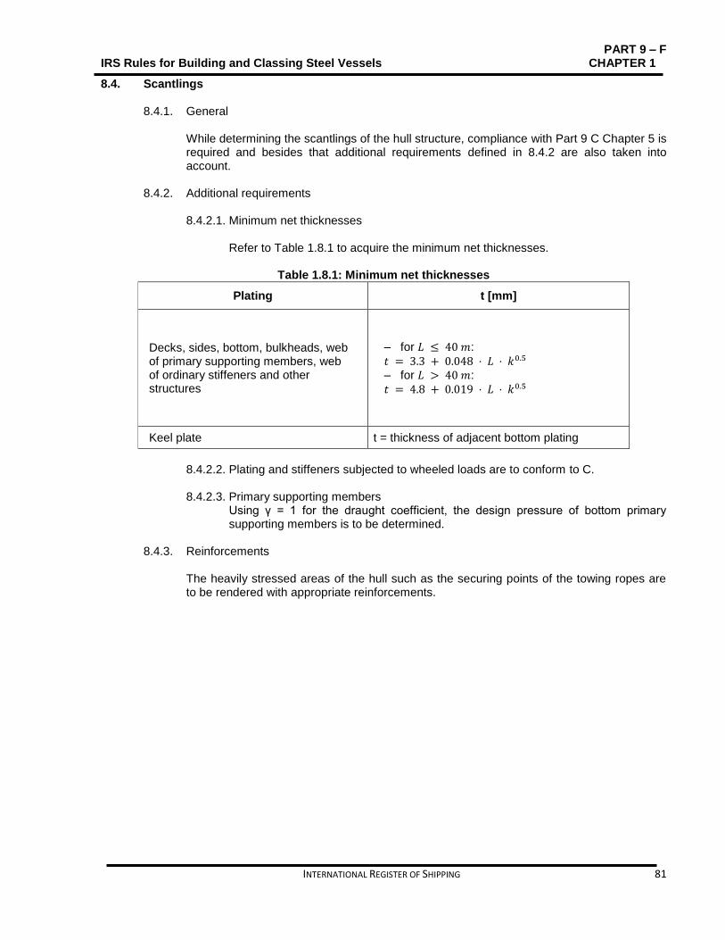
PART 9 – F IRS Rules for Building and Classing Steel Vessels CHAPTER 1
INTERNATIONAL REGISTER OF SHIPPING 81
8.4. Scantlings
8.4.1. General While determining the scantlings of the hull structure, compliance with Part 9 C Chapter 5 is required and besides that additional requirements defined in 8.4.2 are also taken into account.
8.4.2. Additional requirements 8.4.2.1. Minimum net thicknesses
Refer to Table 1.8.1 to acquire the minimum net thicknesses.
Table 1.8.1: Minimum net thicknesses
Plating t [mm]
Decks, sides, bottom, bulkheads, web of primary supporting members, web of ordinary stiffeners and other structures
– for 𝐿 ≤ 40 𝑚:
𝑡 = 3.3 + 0.048 ⋅ 𝐿 ⋅ 𝑘0.5 – for 𝐿 > 40 𝑚:
𝑡 = 4.8 + 0.019 ⋅ 𝐿 ⋅ 𝑘0.5
Keel plate t = thickness of adjacent bottom plating
8.4.2.2. Plating and stiffeners subjected to wheeled loads are to conform to C.
8.4.2.3. Primary supporting members
Using γ = 1 for the draught coefficient, the design pressure of bottom primary supporting members is to be determined.
8.4.3. Reinforcements The heavily stressed areas of the hull such as the securing points of the towing ropes are to be rendered with appropriate reinforcements.

PART 9-F CHAPTER 1 IRS Rules for Building and Classing Steel Vessels
82 INTERNATIONAL REGISTER OF SHIPPING
SECTION 9 VESSELS FOR DREDGING ACTIVITIES Contents
9.1. Symbols ............................................................................................................................................ 83
9.2. General ............................................................................................................................................. 83
9.3. Arrangement ..................................................................................................................................... 84
9.4. Design loads ..................................................................................................................................... 85
9.5. Hull scantlings .................................................................................................................................. 85
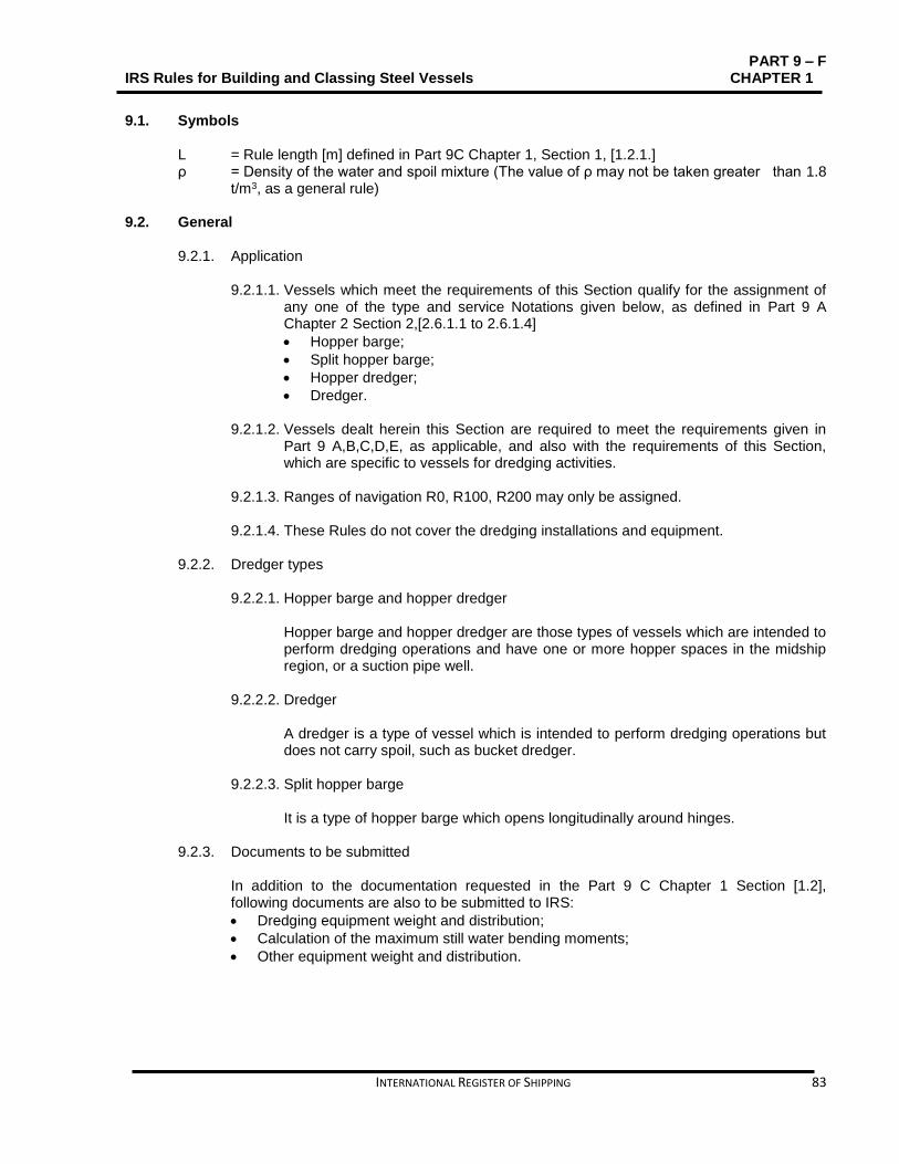
PART 9 – F IRS Rules for Building and Classing Steel Vessels CHAPTER 1
INTERNATIONAL REGISTER OF SHIPPING 83
9.1. Symbols
L = Rule length [m] defined in Part 9C Chapter 1, Section 1, [1.2.1.] ρ = Density of the water and spoil mixture (The value of ρ may not be taken greater than 1.8
t/m3, as a general rule)
9.2. General
9.2.1. Application 9.2.1.1. Vessels which meet the requirements of this Section qualify for the assignment of
any one of the type and service Notations given below, as defined in Part 9 A Chapter 2 Section 2,[2.6.1.1 to 2.6.1.4]
Hopper barge;
Split hopper barge;
Hopper dredger;
Dredger. 9.2.1.2. Vessels dealt herein this Section are required to meet the requirements given in
Part 9 A,B,C,D,E, as applicable, and also with the requirements of this Section, which are specific to vessels for dredging activities.
9.2.1.3. Ranges of navigation R0, R100, R200 may only be assigned. 9.2.1.4. These Rules do not cover the dredging installations and equipment.
9.2.2. Dredger types 9.2.2.1. Hopper barge and hopper dredger
Hopper barge and hopper dredger are those types of vessels which are intended to perform dredging operations and have one or more hopper spaces in the midship region, or a suction pipe well.
9.2.2.2. Dredger A dredger is a type of vessel which is intended to perform dredging operations but does not carry spoil, such as bucket dredger.
9.2.2.3. Split hopper barge It is a type of hopper barge which opens longitudinally around hinges.
9.2.3. Documents to be submitted In addition to the documentation requested in the Part 9 C Chapter 1 Section [1.2], following documents are also to be submitted to IRS:
Dredging equipment weight and distribution;
Calculation of the maximum still water bending moments;
Other equipment weight and distribution.
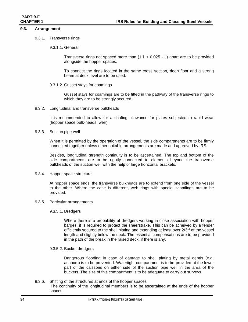
PART 9-F CHAPTER 1 IRS Rules for Building and Classing Steel Vessels
84 INTERNATIONAL REGISTER OF SHIPPING
9.3. Arrangement
9.3.1. Transverse rings 9.3.1.1. General
Transverse rings not spaced more than (1.1 + 0.025 ⋅ L) apart are to be provided alongside the hopper spaces. To connect the rings located in the same cross section, deep floor and a strong beam at deck level are to be used.
9.3.1.2. Gusset stays for coamings
Gusset stays for coamings are to be fitted in the pathway of the transverse rings to which they are to be strongly secured.
9.3.2. Longitudinal and transverse bulkheads It is recommended to allow for a chafing allowance for plates subjected to rapid wear (hopper space bulk-heads, weir).
9.3.3. Suction pipe well When it is permitted by the operation of the vessel, the side compartments are to be firmly connected together unless other suitable arrangements are made and approved by IRS. Besides, longitudinal strength continuity is to be ascertained. The top and bottom of the side compartments are to be rightly connected to elements beyond the transverse bulkheads of the suction well with the help of large horizontal brackets.
9.3.4. Hopper space structure At hopper space ends, the transverse bulkheads are to extend from one side of the vessel to the other. Where the case is different, web rings with special scantlings are to be provided.
9.3.5. Particular arrangements 9.3.5.1. Dredgers
Where there is a probability of dredgers working in close association with hopper barges, it is required to protect the sheerstrake. This can be acheived by a fender efficiently secured to the shell plating and extending at least over 2/3rd of the vessel length and slightly below the deck. The essential compensations are to be provided in the path of the break in the raised deck, if there is any.
9.3.5.2. Bucket dredgers Dangerous flooding in case of damage to shell plating by metal debris (e.g. anchors) is to be prevented. Watertight compartment is to be provided at the lower part of the caissons on either side of the suction pipe well in the area of the buckets. The size of this compartment is to be adequate to carry out surveys.
9.3.6. Shifting of the structures at ends of the hopper spaces
The continuity of the longitudinal members is to be ascertained at the ends of the hopper spaces.

PART 9 – F IRS Rules for Building and Classing Steel Vessels CHAPTER 1
INTERNATIONAL REGISTER OF SHIPPING 85
Using large brackets each having, a rule length and width equal to about 0.25⋅D. the ends of the longitudinal bulkheads are to be extended upwards and downwards. Under the lower brackets, the bottom is to be constrained using a solid keelson extending beyond the bracket end over at least three frame spaces. As a Rule, the coaming sides are to extend beyond the hopper space ends over approx. 1.5 times their height.
9.4. Design loads
9.4.1. Cargo load While determining the cargo load transmitted to the hull structure, compliance with Part 9 C Chapter 5 is required and the cargo density of the water and spoil mixture, shall not be taken less than 1.8.
9.5. Hull scantlings
9.5.1. Split hopper barge As per the applicable requirements of the IRS Rules, scantlings and arrangements of vessels with type and service Notation Split hopper barge will be considered on a case-by-case basis.
9.5.2. Shell plating and topside plating While determining the net scantlings of the shell plating and the topside plating, it is required to conform to the applicable requirements stated in Chapter 1 Section 2, B or Section 8 of this Chapter.
9.5.3. Framing structure 9.5.3.1. While determining the net scantlings of the hull structure, it is required to conform
to the applicable requirements stated in Chapter 1 Section 2, B or Section 8 of this Chapter of this Section.
9.5.3.2. Transverse rings
IRS considers the ring component scantlings on a case-by-case basis. The section modulus at the lower end level for gusset stays for coamings is not to be less than that of the web frames or the side transverses there.
9.5.3.3. Transverse web plates in the side tanks alongside the hopper spaces IRS considers the scantlings of these web plates on a case-by-case basis.
9.5.4. Rudders The rudder stock diameter obtained using Part 9 C Chapter 7 is to be increased by 5%.

PART 9-F CHAPTER 1 IRS Rules for Building and Classing Steel Vessels
86 INTERNATIONAL REGISTER OF SHIPPING
SECTION 10 LAUNCHES Contents
10.1. Symbols ............................................................................................................................................ 87
10.2. Application ........................................................................................................................................ 87
10.3. Hull scantlings .................................................................................................................................. 87

PART 9 – F IRS Rules for Building and Classing Steel Vessels CHAPTER 1
INTERNATIONAL REGISTER OF SHIPPING 87
10.1. Symbols
L = Rule length [m] defined in Part 9C Chapter 1, Section 1, [1.2.1.]; t = Net thickness [mm] of plating; k = Material factor defined in Part 9 C Chapter 2Section 2, [2.3] ;
10.2. Application
10.2.1. Vessels which meet the requirements of this Section qualify for the assignment of the type and service Notation Launch, as defined in Part 9 A Chapter 2 Section 2, [2.7.1.4].
10.2.2. Vessels dealt herein this Section are required to meet the requirements given in Part 9 A B,C,D,E, as applicable, and also with the requirements laid out in this Section, which are specific to launches.
10.3. Hull scantlings
10.3.1. General While determining the scantlings of the hull structure, compliance with Part 9 C Chapter 5 is required and additional requirements of 10.3.2 are also taken into account.
10.3.2. Additional requirements
10.3.2.1. Minimum net thicknesses Refer to Table 10.1.1 to obtain the minimum net thicknesses.
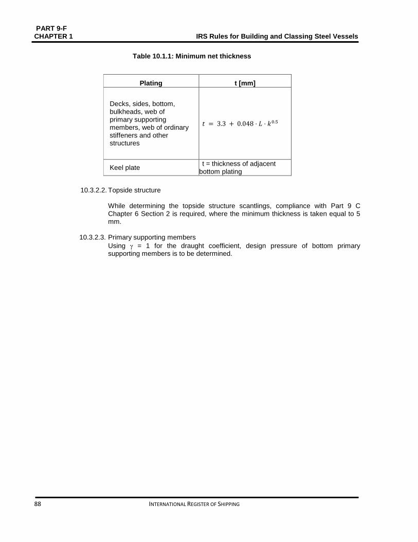
PART 9-F CHAPTER 1 IRS Rules for Building and Classing Steel Vessels
88 INTERNATIONAL REGISTER OF SHIPPING
Table 10.1.1: Minimum net thickness
10.3.2.2. Topside structure While determining the topside structure scantlings, compliance with Part 9 C Chapter 6 Section 2 is required, where the minimum thickness is taken equal to 5 mm.
10.3.2.3. Primary supporting members
Using = 1 for the draught coefficient, design pressure of bottom primary supporting members is to be determined.
Plating t [mm]
Decks, sides, bottom, bulkheads, web of primary supporting members, web of ordinary stiffeners and other structures
𝑡 = 3.3 + 0.048 ⋅ 𝐿 ⋅ 𝑘0.5
Keel plate t = thickness of adjacent
bottom plating
PART 9 – F IRS Rules for Building and Classing Steel Vessels CHAPTER 2
INTERNATIONAL REGISTER OF SHIPPING 89
CHAPTER 2 ADDITIONAL CLASS NOTATIONS
CONTENTS
SECTION 1 TRANSPORT OF HEAVY CARGOES ............................................................................. 90
SECTION 2 EQUIPPED FOR TRANSPORT OFCONTAINERS .......................................................... 93
SECTION 3 EQUIPPED FOR TRANSPORT OF WHEELED VEHICLES ......................................... 101
SECTION 4 FERRY ............................................................................................................................ 103
SECTION 5 STABILITY ...................................................................................................................... 106
SECTION 6 FIRE ................................................................................................................................ 125
SECTION 7 UNATTENDED MACHINERYSPACES (AUT-UMS) ...................................................... 131
SECTION 8 GRABLOADING ............................................................................................................. 140
SECTION 9 POLLUTION PREVENTION (CLEAN VESSEL) ............................................................ 142

PART 9-F CHAPTER 2 IRS Rules for Building and Classing Steel Vessels
90 INTERNATIONAL REGISTER OF SHIPPING
SECTION 1 TRANSPORT OF HEAVY CARGOES
Contents Contents
1.1. All vessels ........................................................................................................................................ 91
1.2. Bulk cargo vessels ........................................................................................................................... 91

PART 9 – F IRS Rules for Building and Classing Steel Vessels CHAPTER 2
INTERNATIONAL REGISTER OF SHIPPING 91
1.1. All vessels
1.1.1. Symbols 𝐿: Rule length, in m, Part 9C Chapter 1, Section 1, [1.2.1]
𝑡: Net thickness, in mm, of plating 𝑠: Spacing, in m, of ordinary stiffeners
ℓ: Span, in m, of ordinary stiffeners or primary supporting members
𝑘: Material factor defined in Part 9C Chapter 2, Section 2, [2.3]
1.1.2. Application
1.1.2.1. In accordance with Part 9A, Chapter 2, Sec 2, [2.3.2.6] to vessels intended to carry
heavy unit cargoes the additional class notation Heavy cargo (𝐴𝑅𝐸𝐴𝑖 , 𝑥𝑖𝑘𝑁/𝑚2), is allocated.
1.1.2.2. Unless otherwise mentioned, these vessels are to comply, as applicable, with the
requirements stated under Part A, Part B, Part C and Chapter 1, Sec 1.
1.1.3. Documentation to be submitted
1.1.3.1. The following information is to be submitted to the Society other than the documentation required in Part B, Chapter 1, Sec 2:
Unit cargo arrangement in holds, on decks and on hatch covers, indicating size and gross mass of cargoes
Drawings of load bearing structures indicating the design loads and including the connections to the hull structures and the associated structural reinforcements.
1.1.4. Design load
1.1.4.1. The designer for each areai according to [1.1.2.1], and introduced as 𝑥𝑖values
needs to specify the value of design pressure𝑝𝑠, in kN/m2.
1.1.5. Hull scantlings 1.1.5.1. General
In general, the hull scantlings are to be not less than required in Part 9C, Chapter 5.
1.2. Bulk cargo vessels
1.2.1. Application
1.2.1.1. The additional class notation Heavy cargo, is assigned, in accordance with Part 9A, Chapter 2, Sec 2, [2.3.2.6] to vessels with type and service notation Bulk cargo vessel intended to carry heavy bulk dry cargoes.
1.2.1.2. Unless otherwise mentioned, these vessels are to comply, as applicable, with the
requirements stated under Part 9A, 9B,9C,9D,9E and Chapter 1, Sec 2.
1.2.2. Design loads
1.2.2.1. According to Part 9C, Chapter 5, and Part 9C, Chapter 4 the still water bending moment and internal local loads are to be decided, respectively, where the cargo properties are not to be taken less than:

PART 9-F CHAPTER 2 IRS Rules for Building and Classing Steel Vessels
92 INTERNATIONAL REGISTER OF SHIPPING
Cargo density, in t/m 3 ρ𝐵 ≥ 2,5
Angle of repose of the bulk cargo
𝜑𝐵 ≥ 35°
1.2.3. Bottom or inner bottom plating thickness
1.2.3.1. According to Part 9F, Chapter 1, Sec 2 the net thickness of bottom or inner bottom plating subjected to heavy bulk dry cargo is to be decided, taking into account the additional requirement stated under [2.2.1]. This thickness, in mm, is not to be less than the value derived from the following formula:
t1=2L1 3⁄ k0,5+3, 6s
PART 9 – F IRS Rules for Building and Classing Steel Vessels CHAPTER 2
INTERNATIONAL REGISTER OF SHIPPING 93
SECTION 2 EQUIPPED FOR TRANSPORT OF CONTAINERS Contents
2.1.General………………………………………………………………………………….….……..94
2.2.Structure Arrangements…………………………………………………………….…..……….94
2.3.Design Loads………………………………………………………………………..……………95
2.4.Hull Scantlings…………………………………………………………………………….……...97
2.5.Direct Calculation…………………………………………………………………..…….…...… 97

PART 9-F CHAPTER 2 IRS Rules for Building and Classing Steel Vessels
94 INTERNATIONAL REGISTER OF SHIPPING
2.1. General
2.1.1. Application
2.1.1.1. As defined in Part 9A, Chapter 2, Sec 2, [2.3.2.2], Vessels complying with the requirements of this Section are entitled for the assignment of the additional class notation Equipped for transport of containers.
2.1.1.2. These vessels are to comply with the requirements stated under Part 9A, Part 9B,
Part 9C,Part 9D,Part 9E and Chapter 1, Sec 1, as far as applicable.
2.1.2. Documentation to be submitted
2.1.2.1. In addition to the documentation required in Part 9C, Chapter 1, Sec 2, the following information is to be submitted to the Society:
Container arrangement in holds, on decks and on hatch covers, indicating size and gross mass of containers
Drawings of load bearing structures indicating the design loads and including the connections to the hull structures and the associated structural reinforcements.
2.2. Structure Arrangements
2.2.1. Strength principles
2.2.1.1. The Designer indicates the forces applied on the fixed cargo securing devices. Local reinforcements of the hull structure are to be given under container corners and in way of fixed cargo securing devices and cell guides, if fitted.
2.2.1.2. Structural continuity
The inner side is to extend as far aft as possible and be tapered at the ends for double hull vessels.
2.2.2. Bottom structure
2.2.2.1. Floor and girder spacing According to recommendation, the floor spacing is to be such that floors are located in way of the container corners. Floors are also to be fitted in way of watertight bulkheads. Girders are generally to be fitted in way of the container corners.
2.2.2.2. Strength continuity
Sufficient strength continuity of floors and bottom transverses is to be maintained in way of the side tank by means of brackets.
2.2.2.3. Reinforcements in way of cell guides The structures of the bottom and inner bottom on which cell guides rest are to be adequately stiffened with doublers, brackets or other equivalent reinforcements.
2.2.3. Hatch covers carrying containers
Effective retaining arrangements are to be provided to avoid translation of the hatch cover under the action of the longitudinal and transverse forces exercised

PART 9 – F IRS Rules for Building and Classing Steel Vessels CHAPTER 2
INTERNATIONAL REGISTER OF SHIPPING 95
by the stacks of containers on the cover. These retaining arrangements are to be located in way of the hatch coaming side brackets. Solid fittings are to be welded on the hatch cover where the corners of the containers will rest. These parts are intended to transmit the loads of the container stacks onto the hatch cover on which they are resting and also to prevent horizontal translation of the stacks by means of special intermediate parts arranged between the supports of the corners and the container corners.
2.3. Design Loads
2.3.1. Design torsional torque
When no specific data are provided by the Designer, the design still water torsional torque induced by the non-uniform distribution of cargo, consumable liquids and ballast is to be obtained at the midship section, in kN.m, from the following formula:
𝑀𝑇 = 31, 4 𝑛𝑠𝑛𝑇𝐵 where:
𝑛𝑠: Number of container stacks over the breadth B
𝑛𝑇: Number of container tiers in cargo hold amid-ships (including containers on hatch covers).
2.3.2. Forces on containers
2.3.2.1. Still water and inertial forces
Forces 𝐹𝑖 applied to one container located at the level “i” As defined in Fig 2.2.2, is to be determined.. The mass of the containers is to be defined by the Designer.
The following values may be used where the mass of loaded containers is not known:
for 40 feet containers: 𝑚𝑖 = 27 𝑡
for 20 feet containers: 𝑚𝑖 = 17 𝑡
The following values may be used where empty containers are stowed at the top of a stack:
0,14 times the weight of a loaded container, in case of empty steel containers
The forces due to the effect of the wind, applied to one container stowed above deck at level i (see Fig 2.2.1), are to be obtained, in kN, from the following formulae:
In x direction
𝐹𝑋,𝑊𝐷,𝑖 = 𝑝𝑊𝐷ℎ𝑐𝑏𝑐
In y direction
𝐹𝑌,𝑊𝐷,𝑖 = 𝑝𝑊𝐷ℎ𝑐ℓ𝑐
Where: ℎ𝑐: Height, in m, of a container
𝐶: Dimension, in m, of the container stack in the vessel longitudinal and transverse
direction, respectively 𝑝𝑊𝐷 Specific wind pressure, in kN/m2, defined in Table 2.2.1 These forces are only acting on the stack exposed to wind.

PART 9-F CHAPTER 2 IRS Rules for Building and Classing Steel Vessels
96 INTERNATIONAL REGISTER OF SHIPPING
In the case of 𝑀 juxtaposed and connected stacks of the same height, the wind
forces are to be distributed over the 𝑀 stacks.
0.08 times the weight of a loaded container, in case of empty aluminium containers.
2.3.2.2. Wind forces applied to one container
In the case of juxtaposed and connected stacks of different heights, the wind forces are to be distributed taking into account the number of stacks at the level considered (see example in Fig 2.2.4.
Table 2.2.1: Specific wind pressure
Navigation Notation 𝑝𝑊𝐷, in kN/m2
IN(1,2 ≤ x ≤ 2) 0,3 𝑛0,5
IN(0,6), IN(0) 0,25
2.3.2.3. Stacks of containers
The still water, inertial and wind forces to be considered as being applied at the centre of gravity of the stack, and those transmitted at the corners of such stack is to be obtained, in kN, as specified in Table 2.2.2.
2.3.2.4. Securing load
The scantling load of securing devices is to be determined assuming an angle of list of 12°.

PART 9 – F IRS Rules for Building and Classing Steel Vessels CHAPTER 2
INTERNATIONAL REGISTER OF SHIPPING 97
Figure 2.2.1: Containers level in a stack
2.4. Hull Scantlings
2.4.1. General
2.4.1.1. Generally, the hull scantlings are to be not less than required in Part 9C, Chapter 5. 2.4.1.2. Scantlings of structural members subjected to concentrated loads are to be
determined by direct calculation and submitted to IRS for approval. 2.4.1.3. Where the operating conditions (loading / unloading sequence as well as
consumable and ballast distribution) are likely to induce excessive torsional torque, the torsional strength is to be checked, using the design torsional torque derived from [2.3.1.1].
2.5. Direct Calculation
2.5.1. General 2.5.1.1. Direct calculation is to be performed in compliance with IRS guidelines. These
requirements apply to the grillage analysis of primary supporting members subjected to concentrated loads.
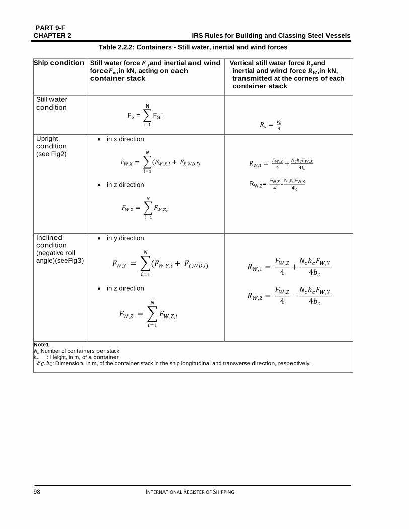
PART 9-F CHAPTER 2 IRS Rules for Building and Classing Steel Vessels
98 INTERNATIONAL REGISTER OF SHIPPING
Table 2.2.2: Containers - Still water, inertial and wind forces
Ship condition Still water force 𝑭 𝒔and inertial and wind
force𝑭𝒘,in kN, acting on each container stack
Vertical still water force 𝑹𝒔and
inertial and wind force 𝑹𝑾,in kN, transmitted at the corners of each container stack
Still water condition
FS = ∑ FS,i
N
i=1
𝑅𝑠 = 𝐹𝑠
4
Upright condition (see Fig2)
in x direction
𝐹𝑊,𝑋 = ∑(𝐹𝑊,𝑋,𝑖
𝑁
𝑖=1
+ 𝐹𝑋,𝑊𝐷.𝑖)
in z direction
𝐹𝑊,𝑍 = ∑ 𝐹𝑊,𝑍,𝑖
𝑁
𝑖=1
𝑅𝑊,1 = 𝐹𝑊,𝑍
4+
𝑁𝑐ℎ𝑐𝐹𝑊,𝑋
4𝑙𝑐
RW,2= FW,Z
4-
NchcFW,X
4lc
Inclined condition (negative roll angle)(seeFig3)
in y direction
𝐹𝑊,𝑌 = ∑(𝐹𝑊,𝑌,𝑖
𝑁
𝑖=1
+ 𝐹𝑌,𝑊𝐷,𝑖)
in z direction
𝐹𝑊,𝑍 = ∑ 𝐹𝑊,𝑍,𝑖
𝑁
𝑖=1
𝑅𝑊,1 = 𝐹𝑊,𝑍
4+
𝑁𝑐ℎ𝑐𝐹𝑊,𝑌
4𝑏𝑐
𝑅𝑊,2 = 𝐹𝑊,𝑍
4−
𝑁𝑐ℎ𝑐𝐹𝑊,𝑌
4𝑏𝑐
Note1:
𝑁𝑐:Number of containers per stack ℎ𝑐 : Height, in m, of a container ℓ𝐶, 𝑏𝐶: Dimension, in m, of the container stack in the ship longitudinal and transverse direction, respectively.

PART 9 – F IRS Rules for Building and Classing Steel Vessels CHAPTER 2
INTERNATIONAL REGISTER OF SHIPPING 99
Figure 2.2.2: Inertial and wind forces
Upright Vessel condition
Figure 2.2.3: Inertial and wind forces Inclined Vessel condition

PART 9-F CHAPTER 2 IRS Rules for Building and Classing Steel Vessels
100 INTERNATIONAL REGISTER OF SHIPPING
Figure 2.2.4: Distribution of wind forces in the case of stacks of different heights
PART 9 – F IRS Rules for Building and Classing Steel Vessels CHAPTER 2
INTERNATIONAL REGISTER OF SHIPPING 101
SECTION 3 EQUIPPED FOR TRANSPORT OF WHEELED VEHICLES Contents
3.1. General ........................................................................................................................................... 102
3.2. Vessel arrangements ...................................................................................................................... 102
3.3. Scantlings ....................................................................................................................................... 102

PART 9-F CHAPTER 2 IRS Rules for Building and Classing Steel Vessels
102 INTERNATIONAL REGISTER OF SHIPPING
3.1. General
3.1.1 Application
3.1.1.1. The Vessels which fulfill the requirements of this Section are eligible for the assignment of the additional class Notation Equipped for transport of wheeled vehicles, as defined in Part 9A, Chapter 2, Sec 2, [2.3.2.3].
3.1.1.2. These vessels are to comply with the requirements stated under Part 9A, Part 9B, Part 9C, Part 9D, Part 9E and Chapter 1, Sec 1, as far as applicable.
3.1.2 Documentation to be submitted
3.1.2.1. Other than the documentation required in Part 9C Chapter 1 Sec 2 , a wheeled vehicle arrangement plan including the following details:
type of vehicles
axle load
configuration and number of wheels per axle
distance between axles
distance between wheels
tyre imprint area is to be submitted to the Society.
3.2. Vessel arrangements
3.2.1. Sheathing
3.2.1.1. Wood sheathing is mentioned for caterpillar trucks and unusual vehicles.
It is recommended that a piece of wood of suitable thickness should be given under each crutch in order to distribute the mass over the plate and the nearest stiffeners.
3.2.2. Hull structure
3.2.2.1. Framing
Generally, Ro-Ro cargo decks or platforms are to be longitudinally framed. It is to be considered by the Society on a case by case basis when a transverse framing system is adopted.
3.2.3. Drainage of cargo spaces, other than Ro-Ro spaces, intended for the carriage of motor vehicles with fuel in their tanks for their own propulsion
3.2.3.1. Scupper draining
Other than Ro-Ro spaces, Scuppers from cargo spaces, proposed for the carriage of motor vehicles with fuel in their tanks for their own propulsion are not to be directed to machinery or other places where sources of ignition may be present.
3.3. Scantlings
3.3.1. Ro-Ro cargo spaces
3.2.2.1. Design loads
The wheeled loads induced by vehicles are to be considered
3.2.2.2. The scantlings of RoRo cargo spaces are to be in compliance with Chapter 1, Sec 5, [5.3].
3.3.2. Movable decks and inner ramps
The requirements applicable to movable decks and inner ramps are to be considered.
3.3.3. External ramps
The requirements applicable to external ramps are to be considered.

PART 9 – F IRS Rules for Building and Classing Steel Vessels CHAPTER 2
INTERNATIONAL REGISTER OF SHIPPING 103
SECTION 4 FERRY Contents
4.1. General ........................................................................................................................................... 104
4.2. Plan of dangerous areas, in the case of vessels intended for the carriage of motor vehicles with
petrol in their tanks Vessel arrangements ............................................................................................... 104
4.3. Scantlings ....................................................................................................................................... 105
4.4. Electrical installations ..................................................................................................................... 105

PART 9-F CHAPTER 2 IRS Rules for Building and Classing Steel Vessels
104 INTERNATIONAL REGISTER OF SHIPPING
4.1. General
4.1.1. Application 4.1.1.1. The Passenger vessels which need to fulfill the requirements of this Section are
eligible for the assignment of the additional class notation Ferry, as defined in Part 9A, Chapter 2, Sec 2, [2.5.2.1].
4.1.1.2. As far as applicable these vessels are to comply with the requirements stated
under Part 9A, Part 9B, Part 9C,Part 9D,Part 9E and Chapter 1, Sec 6.
4.1.2. Documentation to be submitted 4.1.2.1. Other than the documentation required in Part 9C Chapter 1 Sec 2, the following
information is to be submitted:
a) Plans of ramps, elevators for cargo handling and movable decks, if any, including:
structural arrangements of ramps, elevators and movable decks with their masses
arrangements of securing and locking devices
connection of ramps, lifting and/or hoisting appliances to the hull structures, with indication of design loads (amplitude and direction)
wire ropes and hoisting devices in working and stowed position
details of hydraulic jacks
loose gear (blocks, shackles, etc.) indicating the safe working loads and the testing loads
test conditions
b) Plan of arrangement of motor vehicles, railway bogies and/or other types of vehicles which are intended to be carried indicating securing and load bearing arrangements
c) Characteristics of motor vehicles, railways bogies and/or other types of vehicles which are intended to be carried:(as applicable) axle load, axle spacing, number of wheels per axle, wheel spacing, size of tyre imprint
4.2. Plan of dangerous areas, in the case of vessels intended for the carriage of motor vehicles
with petrol in their tanks.
4.2.1. Sheathing
4.2.1.1. Wood sheathing is mentioned for caterpillar trucks and unusual vehicles.
It is recommended that a piece of wood of suitable thickness should be given under each crutch in order to distribute the mass over the plate and the nearest stiffeners.
4.2.2. Hull structure
4.2.2.1. Framing
Generally, car decks or platforms are to be longitudinally framed. It is to be considered by the Society on a case-by-case basis where a transverse framing system is adopted.
4.2.3. Drainage of Ro-Ro cargo spaces, intended for the carriage of motor vehicles with fuel in tanks for their own propulsion

PART 9 – F IRS Rules for Building and Classing Steel Vessels CHAPTER 2
INTERNATIONAL REGISTER OF SHIPPING 105
4.2.3.1. Scupper draining
Scuppers from cargo spaces aimed for the carriage of motor vehicles with fuel in tanks for their own propulsion are not to be directed to machinery or other places where sources of ignition may be present.
4.3. Scantlings
4.3.1. Ro-Ro cargo spaces
4.3.1.1. Design loads
The wheeled loads induced by vehicles are to be considered.
4.3.1.2. The scantlings of Ro-Ro cargo spaces are to be in compliance with Chapter 1, Sec 5, [5.4].
4.3.2. Movable decks and inner ramps
4.3.3.1. The requirements applicable to movable decks and inner ramps are to be considered.
4.3.3. External ramps
4.3.3.2. The requirements applicable to external ramps will be considered separetly
4.4. Electrical installations
4.4.1. Protective measures on car decks
4.4.1.1. Special category spaces: definition
Special category spaces are those enclosed vehicle spaces above and below the bulkhead deck, into and from which vehicles can be driven and to which passengers have access. Special category spaces may be accommodated on more than one deck.
4.4.1.2. Installations in special category spaces situated above the bulkhead deck
Electrical equipment and cables are to be installed at least 450 mm above the deck or platform where vehicles are carried and on which explosive vapours might be expected to accumulate except for platforms with openings of sufficient size permitting penetration of petrol gases downwards. The electrical equipment is to be of a certified safe type as stated in Part 7 and to have the minimum explosion group IIA and temperature class T3 where the installation of electrical equipment and cables at less than 450 mm above the deck or platform is thought necessary for the safe operation of the vessel,. Electrical equipment is to be as stated in Part 7
4.4.1.3. Electrical equipment installed is to be as stated in Part 7 and to have the minimum
explosion group IIA and temperature class T3 where installations in special category spaces situated below the bulkhead deck.
4.4.1.4. Ventilation
Electrical equipment and cables in exhaust ventilation ducts are to be as stated in Part 7 and to have the minimum explosion group IIA and temperature class T3.
PART 9-F CHAPTER 2 IRS Rules for Building and Classing Steel Vessels
106 INTERNATIONAL REGISTER OF SHIPPING
SECTION 5 STABILITY Contents
5.1. General ........................................................................................................................................... 107
5.2. General cargo vessels and RoRocargo vessels ............................................................................ 107
5.3. Bulk cargo vessels ......................................................................................................................... 108
5.4. Container vessels ........................................................................................................................... 109
5.5. Tankers .......................................................................................................................................... 114
5.6. Tugs ............................................................................................................................................... 114
5.7. Pushers .......................................................................................................................................... 115
5.8. Pontoons ........................................................................................................................................ 116
5.9. Dredgers ......................................................................................................................................... 118
5.10. Hopper dredgers and hopper barges ............................................................................................. 121
PART 9 – F IRS Rules for Building and Classing Steel Vessels CHAPTER 2
INTERNATIONAL REGISTER OF SHIPPING 107
5.1. General
5.1.1. Symbols 𝐿: Rule length, in m, defined in Part 9C Chapter 1, Section 1, [1.2.1] 𝐵: Breadth, in m, defined in Part 9C Chapter 1, Section 1, [1.2.1]
𝐷: Depth, in m, defined in Part 9C Chapter 1, Section 1, [1.2.1]
𝑇: Draught, in m, defined in Part 9C Chapter 1, Section 1, [1.2.1]
𝐿𝑊𝐿: Length of waterline, in m, defined in Part 9C Chapter 1, Section 1, [1.2.1] 𝐿𝑂𝐴 : Length overall, in m, defined in Part 9C Chapter 1, Section 1, [1.2.1]
𝛥: Displacement, in tons, at draught T
𝐶𝐵: Block coefficient, defined in Part 9C Chapter 1, Section 1, [1.2.1] 𝑣: Maximum speed of the vessel in relation to the water, in km/h
𝐾𝐺 ∶ Height, in m, of the centre of gravity above baseline
𝑛: Navigation coefficient defined in Part 1
5.1.2. Application
5.1.2.1. Vessels complying with the requirements of this Section are eligible for the assignment of one of the following additional class notations, as defined in Part 9A, Chapter 2, Sec 2,[2.9.4]:
Intact stability
Damage stability
5.1.2.2. Rules applicable to various vessel types The requirements of this Section are to be applied for assessment of various vessel stability according to Table 2.5.1.
5.1.3. Documents to be submitted
5.1.3.1. The documents to be submitted are listed in Part 9C, Chapter 1, Sec 2,.The Society may require any other necessary guidance for the safe operation of the vessel.
5.2. General cargo vessels and Ro-Ro cargo vessels
5.2.1. Intact stability
5.2.1.1. The general requirements of Part 9C, Chapter 5 are to be complied with.
Table2.5.1: Requirements applicable to various vessel types
Vessel type Applicable requirements
All types ****
General cargo vessels ****
RoRo cargo vessels
Bulk cargo vessels ****
Container vessels ****
Tankers ****
Tugs ****
Pushers ****
Pontoons ****
Dredgers ****
Hopper dredgers ****
Hopper barges
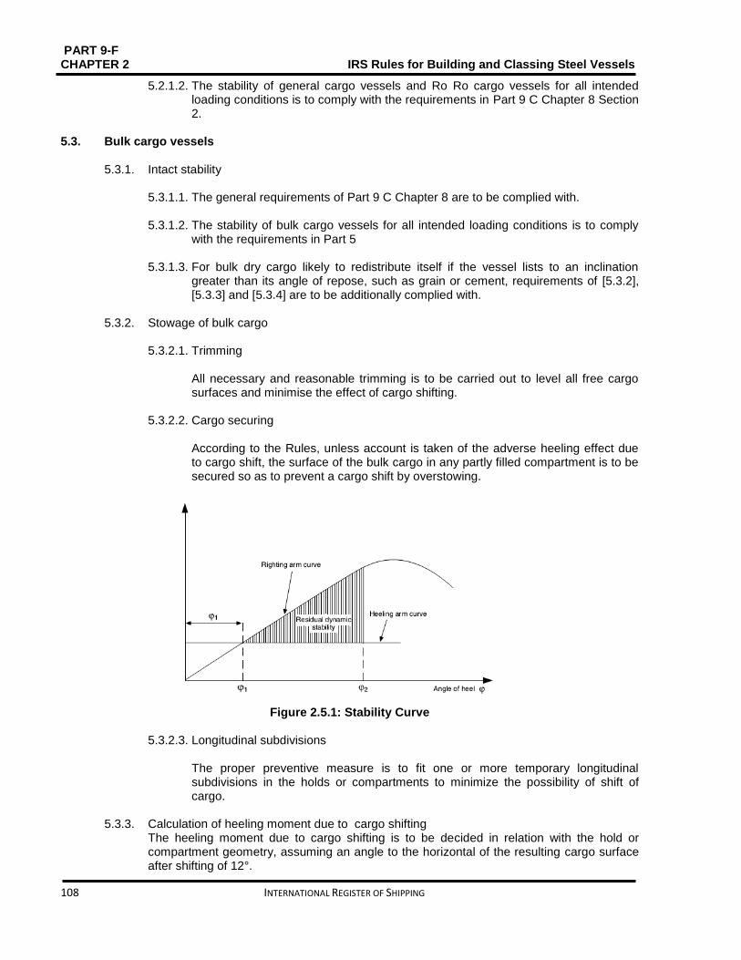
PART 9-F CHAPTER 2 IRS Rules for Building and Classing Steel Vessels
108 INTERNATIONAL REGISTER OF SHIPPING
5.2.1.2. The stability of general cargo vessels and Ro Ro cargo vessels for all intended loading conditions is to comply with the requirements in Part 9 C Chapter 8 Section 2.
5.3. Bulk cargo vessels
5.3.1. Intact stability
5.3.1.1. The general requirements of Part 9 C Chapter 8 are to be complied with. 5.3.1.2. The stability of bulk cargo vessels for all intended loading conditions is to comply
with the requirements in Part 5
5.3.1.3. For bulk dry cargo likely to redistribute itself if the vessel lists to an inclination greater than its angle of repose, such as grain or cement, requirements of [5.3.2], [5.3.3] and [5.3.4] are to be additionally complied with.
5.3.2. Stowage of bulk cargo
5.3.2.1. Trimming
All necessary and reasonable trimming is to be carried out to level all free cargo surfaces and minimise the effect of cargo shifting.
5.3.2.2. Cargo securing
According to the Rules, unless account is taken of the adverse heeling effect due to cargo shift, the surface of the bulk cargo in any partly filled compartment is to be secured so as to prevent a cargo shift by overstowing.
Figure 2.5.1: Stability Curve
5.3.2.3. Longitudinal subdivisions
The proper preventive measure is to fit one or more temporary longitudinal subdivisions in the holds or compartments to minimize the possibility of shift of cargo.
5.3.3. Calculation of heeling moment due to cargo shifting The heeling moment due to cargo shifting is to be decided in relation with the hold or compartment geometry, assuming an angle to the horizontal of the resulting cargo surface after shifting of 12°.

PART 9 – F IRS Rules for Building and Classing Steel Vessels CHAPTER 2
INTERNATIONAL REGISTER OF SHIPPING 109
5.3.4. Additional intact stability criteria
5.3.4.1. The intact stability characteristics of any vessel carrying bulk dry cargo likely to
reallocate itself if the vessel lists to an inclination greater than its angle of repose, such as grain or cement, are to be shown to meet, throughout the voyage, at least the following criteria after taking into account the heeling moment due to cargo shifting (see Fig 2.5.1):
The angle of heel 𝜙1due to the shift of cargo is not to be greater than 12° or the angle at which the deck edge is immersed, whichever is the lesser
In statical stability diagram, the net or residual area between the heeling arm curve and the righting arm curve up to the angle of heel 𝜙2of maximum difference between the ordinates of the two curves, or 27° or the angle of flooding, whichever is the lesser, is in all conditions of loading to be not less than 0,024 m.rad
The initial metacentric height, after correction for the free surface effects of liquids in tanks, is to be not less than 0.15 m.
5.4. Container vessels
5.4.1. General
5.4.1.1. The general conditions of Part 9 C Chapter 8 are to be complied with.
5.4.2. Stowage of containers
5.4.2.1. Secured containers If each individual container is firmly secured to the hull structure of the vessel by means of rails or turnbuckles and its position cannot alter during the voyage then a cargo of containers shall be considered to be secured.
5.4.2.2. Separate documents concerning stability are required for the carriage of each type
of container in the case of vessels likely to carry either secured or non-secured containers.
5.4.3. Intact stability in the case of non-secured containers
5.4.3.1. All methods of calculating a vessel’s stability in the case of non-secured containers
shall meet the following limit conditions:
a) Metacentric height, 𝐺𝑀, shall not be less than 1,00 m. b) Under the joint action of the wind thrust, centrifugal force resulting from the
vessel’s turning and the effect of free surfaces induced by the hold or double bottom fillings, the angle of heel shall not exceed 5° and the edge of the deck shall not be dipped.
5.4.3.2. The heeling lever, in m, resulting from the centrifugal force caused by the vessel
turning shall be determined in accordance with the following formula:
ℎ𝐾𝑍 = 0.00308𝑣2
𝐿𝑊𝐿(𝐾𝐺 −
𝑇
2)
5.4.3.3. The heeling lever, in m, resulting from the wind thrust is to be determined in
accordance with the following formula:
ℎ𝐾𝑊 = 0.1𝑝𝑊𝐷
𝐴𝑤
∆(𝑙𝑤 +
𝑇
2)

PART 9-F CHAPTER 2 IRS Rules for Building and Classing Steel Vessels
110 INTERNATIONAL REGISTER OF SHIPPING
Where 𝑝𝑊𝐷 : Specific wind pressure, in kN/m2
for R0 and R100: 𝑃𝑊𝐷 = 0,25
for R100 and R200: 𝑃𝑊𝐷 = 0,3 𝑛0,5
𝐴𝑤: Side surface above the waterline of the loadedvessel, in m2 ℓW : Height, in m, of the centre of gravity of the side surface AW above the waterline.
5.4.3.4. The heeling lever, in m, resulting from the free surfaces of rainwater and residual water within the hold or the double bottom shall be determined in accordance with the following formula:
ℎ𝐾𝐹𝑂 = 0.015
∇∑[ 𝑏𝑙(𝑏 − 0.55√𝑏)]
Where: 𝑏:Width of hold or section of the hold in question, in m
ℓ: Length of hold or section of the hold in question, in m.
5.4.3.5. For each loading condition, half of the fuel and fresh water supply shall be taken into account.
5.4.3.6. The stability of a vessel carrying non-secured containers shall be considered to be
sufficient if the effective 𝐾𝐺 does not exceed the 𝐾𝐺𝑍determined according to [5.4.3.7].
5.4.3.7. 𝐾𝐺𝑍is the maximum permissible height, in m, of the loaded vessel’s centre of
gravity above its base. 𝐾𝐺𝑍shall be calculated for various displacements covering all of the possible draught variations, according to the following formulae
𝐾𝐺𝑧 = 𝐾𝑀 +
𝐵𝑊𝐿
2𝐹(𝑍𝑧
𝑇𝑚
2− ℎ𝐾𝑊 − ℎ𝐾𝐹𝑂)
𝐵𝑊𝐿
2𝐹𝑍𝑧 + 1
Or 𝐾𝐺𝑍 = 𝐾𝑀 − 1
Whichever is the smaller, where:
𝐵𝑊𝐿/2𝐹 > 11, 5
𝐾𝑀: Height of the metacentre above the base, in m.
If no curve diagram is available the value of 𝐾𝑀 may be decided, for example, via the following approximation formulae:
vessels in the form of a pontoon
𝐾𝑀 =𝐵𝑊𝐿
2
(12. 5 − 𝑇𝑚
𝐷)𝑇𝑚
+𝑇𝑚
2
other vessels
𝐾𝑀 =𝐵𝑊𝐿
2
(12. 7 − 1.2 𝑇𝑚
𝐷)𝑇𝑚
+𝑇𝑚
2
𝐹: Effective freeboard at 0.5 LOA
𝐵𝑊𝐿: Vessel waterline breadth, in m
𝑇𝑚: Average draught, in m 𝑍𝑧: Parameter for the centrifugal force resulting from turning:

PART 9 – F IRS Rules for Building and Classing Steel Vessels CHAPTER 2
INTERNATIONAL REGISTER OF SHIPPING 111
𝑍𝑧 = 0.00308 𝑣2
𝐿𝑊𝐿
5.4.4. Intact stability in the case of secured containers
5.4.4.1. All means of calculation used in order to determine vessel stability shall meet the following limit conditions In the case of secured containers:
Metacentric height 𝐺𝑀 shall be not to be less than 0,50 m
No hull opening shall be immersed by the combined action of the centrifugal force resulting from the turning of the vessel, wind thrust and free surfaces of liquids in tanks and holds.
5.4.4.2. In accordance with [5.4.3], the heeling moments resulting from the wind thrust,
centrifugal force due to vessel’s turning and free surfaces of liquids, are to be decided. For each loading condition half of the supply of fuel and fresh water shall be taken into account.
5.4.4.3. If the effective 𝐾𝐺 does not exceed the 𝐾𝐺𝑍determined according to [5.4.4.4], the
stability of a vessel carrying secured containers shall be considered to be satisfactory.
5.4.4.4. 𝐾𝐺𝑍 is the maximum permissible height, in m, of the loaded vessel’s centre of
gravity above its base. 𝐾𝐺𝑍shall be calculated for various displacements covering all of the possible draught variations, according to the following formulae:
𝐾𝐺𝑧 = 𝐾𝑀 − 𝐾𝑀1 + 𝐾𝑀2
0, 75 𝐵𝑊𝐿
𝐹∗ 𝑍𝑍 + 1
Or
𝐾𝐺𝑧 = 𝐾𝑀 − 0,5
Whichever is the lesser
5.4.5. Damage stability 5.4.5.1. Application
The requirements of this sub-article apply to vessels exceeding 110 m in length in addition to the rules stated under [5.4.3] and [5.4.4].
5.4.5.2. For the most unfavorable loading condition the proof of sufficient stability after
damage is to be produced. The basic values for the stability calculation - the vessel's lightweight and location of the centre of gravity - shall be decided:
Either by means of an heeling experiment, or
By detailed mass and moment calculation, in which case the lightweight of the vessel shall be verified by checking the draught, with a tolerance limit of ±5% between the mass determined by calculation and the displacement determined by the draught readings.
5.4.5.3. For the fully loaded vessel the proof of floatability after damage shall be produced.
For this purpose, calculated proof of sufficient stability shall be established for the critical intermediate stages of flooding and for the final stage of flooding. Negative values of stability in intermediate stages of flooding may be admitted only if the

PART 9-F CHAPTER 2 IRS Rules for Building and Classing Steel Vessels
112 INTERNATIONAL REGISTER OF SHIPPING
continued range of curve of righting lever in damaged condition indicates adequate positive values of stability.
5.4.5.4. The following assumptions shall be taken into account for the damaged condition:
a) Extent of side damage:
longitudinal extent: at least 0.10 𝐿𝑂𝐴
transverse extent: 0.59 m
vertical extent: from base line upwards without limit
b) Extent of bottom damage:
longitudinal extent: at least 0.10 𝐿𝑂𝐴
transverse extent: 3.00 m
vertical extent: from base line to 0.49 m upwards, the sump excepted
c) Any bulkhead within the damaged area shall be assumed damaged, which means that the location of the bulkheads shall be chosen so that the vessel remains afloat after flooding of two or more adjacent compartments in the longitudinal direction. For the main engine room only one-compartment status needs to be taken into account, i.e. the end bulkheads of the engine room shall be assumed as not damaged. For bottom damage, adjacent athwartship compartments shall also be accepted as flooded.
d) Permeability
Permeability shall be accepted to be 95%. By way of derogation from this assumption, the values of permeability stated in Tab 2.5.2 may be assumed. If a calculation proves that the average permeability of any compartment is lower, the calculated value may be used.
e) At the final stage of flooding the lower edge of any non-watertight opening (e.g. doors, windows, access hatches) shall not be less than 100 mm above the damaged waterline.
Table 2.5.2: Permeability values, in %
Spaces 𝝁
Engine and service rooms 85
Accommodation spaces 95
Double bottoms, fuel tanks, ballast tanks, etc. depending on whether, according to their function, they have to be assumed as full or empty for the vessel floating at the maximum permissible draught
0 or 95
5.4.5.5. The stability after damage shall be adequate if, on the basis of the assumptions in
[5.4.5.4]:
a) At the final stage of flooding a safety clearance of not less than 100 mm remains and the angle of heel of the vessel does not exceed 5°
b) Or, for secured containers (see Fig 2.5.2)
PART 9 – F IRS Rules for Building and Classing Steel Vessels CHAPTER 2
INTERNATIONAL REGISTER OF SHIPPING 113
The angle of heel is not greater than 12° at the stage of equilibrium (in the final stage of flooding).
Non-watertight openings shall not be flooded before reaching the stage of equilibrium. The corresponding spaces shall be considered flooded for the purpose of stability calculation if such openings are immersed before the stage of equilibrium.
The positive range of the righting lever curve beyond the stage of equilibrium has a righting lever of ≥ 0,05 𝑚 in association with an
area under the curve of ≥ 0,0065 𝑚. 𝑟𝑎𝑑. The minimum values of stability shall be satisfied up to immersion of the first non-weathertight openings and in any event up to an angle of heel ≤ 27°. If non- watertight openings are immersed before that stage, the corresponding spaces shall be considered flooded for the purpose of stability calculation.
c) or, for non-secured containers (see Fig 2.5.3)
At the stage of equilibrium (final stage of flooding), the angle of heel shall not exceed 5°. Non-water-tight openings shall not be immersed before reaching the stage of equilibrium. The corresponding spaces shall be considered as flooded for the purpose of stability calculation if such openings are immersed before that stage.
The positive range of the righting lever curve beyond the position of equilibrium shall have an 𝑎𝑟𝑒𝑎 𝑢𝑛𝑑𝑒𝑟 𝑡ℎ𝑒 𝑐𝑢𝑟𝑣𝑒 𝑜𝑓 = 0, 0065 𝑚. 𝑟𝑎𝑑. The minimum values of stability shall be satisfied up to immersion of the first non-weathertight opening and in any event up to an 𝑎𝑛𝑔𝑙𝑒 𝑜𝑓 ℎ𝑒𝑒𝑙 = 10°. The corresponding spaces shall be considered as flooded for the purposes of stability calculation if non-weathertight openings are immersed before that stage.
5.4.5.6. The time for equalization shall not exceed 15 minutes when cross-or down flooding
openings are provided for reduction of unsymmetrical flooding and if during the intermediate stages of flooding sufficient damaged stability has been demonstrated.
5.4.5.7. The closing appliances shall be marked according to their operating instructions
when openings through which undamaged compartments may additionally become flooded are capable of being closed watertight.
5.4.5.8. The plane of maximum draught shall be re-established where necessary in order to
meet the requirements in [5.4.5.2] or [5.4.5.3.].

PART 9-F CHAPTER 2 IRS Rules for Building and Classing Steel Vessels
114 INTERNATIONAL REGISTER OF SHIPPING
Figure 2.5.2: Proof of damage stability for container vessels carrying secured containers
5.5. Tankers
5.5.1. General
5.5.1.1. The general requirements of Part 9C Chapter 8 are to be complied with. 5.5.1.2. The centre longitudinal bulkhead may be given out with only if sufficient stability is
guaranteed.
5.5.2. Intact stability
5.5.2.2. The stability of tankers for all intended loading conditions is to comply with the requirements in Part 9C, Chapter 8, Sec 2.
5.6. Tugs
5.6.1. General The general requirements of Part 9C Chapter 8 are to be complied with.
The stability of tugs for all intended loading conditions is to comply with the requirements in *****.
5.6.2. Additional intact stability 5.6.2.1. In order to investigate the vessel’s capability to support the effect of the towing
force in the beam direction, all intended loading conditions are also to be checked. A tug may be considered as having sufficient stability, according to the effect of the towing force in the beam direction, if the following condition is complied with:
𝐴 ≥ 0. 011
where: A Area, in m.rad, contained between the righting lever and the heeling arm curves, measured from the heeling angle 𝜑𝑐 to the heeling angle
𝜑𝐷

PART 9 – F IRS Rules for Building and Classing Steel Vessels CHAPTER 2
INTERNATIONAL REGISTER OF SHIPPING 115
𝜑𝐶Heeling angle of equilibrium, corresponding to the first intersection between healing and righting arms 𝜑𝐷Heeling angle, to be taken as the lowest of:
the angle 𝜑𝑀, corresponding to the position of 𝐺𝑍𝑀𝐴𝑋 (see Fig. 2.5.4)
the angle of downflooding
Figure 2.5.4: Heeling and righting arms curves
The heeling arm curve is to be calculated as follows:
bH = THc
9,81Δcos φ
Where bH: Heeling arm, in mm
T: Maximum towing pull, in kN Where this force is unknown, it can be assumed equal to: T = 0, 179 P for propellers not fitted with nozzles
T = 0, 228 P for propellers fitted with nozzles
P : Maximum continuous power, in kW, of the propulsion engine H : Vertical distance, in m, between the towing hook, or equivalent fitting, and
half draught corresponding to Δ
c : Coefficient defined as: c = 1,00 for vessels with non-azimuth propulsion
c = 0,65 for vessels with non-azimuth propulsion
Δ :Loading condition displacement, in t
5.7. Pushers
5.7.1. General
5.7.1.1. The general requirements of Part 9 C are to be complied with. 5.7.1.2. The stability of pushers for all intended loading conditions is to comply with the
requirements in Part 5
PART 9-F CHAPTER 2 IRS Rules for Building and Classing Steel Vessels
116 INTERNATIONAL REGISTER OF SHIPPING
5.8. Pontoons
5.8.1. General
5.8.1.1. The general requirements of Part 9 C Chapter 8 are to be complied with.
5.8.2. Documentation to be submitted
5.8.2.1. Additionally to the documentation referred to in [5.1.2], stability confirmation shall contain the following data and documents:
a) Scale drawings of the pontoon and working gear and the detailed data relating to these that are needed to confirm stability, such as content of the tanks, openings pro-viding access to the inside of the vessel, etc.
b) Hydrostatic data or curves c) Righting lever curves for static stability to the extent required in accordance
with [5.8.4] d) Description of the operating conditions together with the corresponding
data concerning weight and centre of gravity, including its unladen state and the equipment situation as regards transport
e) Calculation of the heeling, trimming and righting moments, with specification of the list and trim angles and the corresponding residual freeboard and residual safety clearances
f) All of the results of the calculation with a specification of the use and load limits.
5.8.3. Heeling moments
5.8.3.1. Load induced moment
The Designer defines the load induced moment. 5.8.3.2. Asymmetric structure induced moment
The Designer defines the asymmetric structure induced moment.
5.8.3.3. Moment due to wind pressure
The moment caused by the wind pressure, in kNm, shall be calculated in accordance with the following formula:
𝑀𝑤 = 𝑐 𝑃𝑊𝐷 𝐴𝑤(𝑙𝑤 + 𝑇 2⁄ ) Where: 𝐶 : Shape dependent coefficient of resistance taking account of gusts:
For frameworks: 𝑐 = 1,2
For solid section beam: 𝑐 = 1,6 𝑃𝑊𝐷 : Specific wind pressure, in kNm2
for R0 and R100: 𝑃𝑊𝐷 = 0,25
for R100and R200: PWD = 0,3 n0,5 𝐴𝑤: Side surface above the waterline of the loadedvessel, in m2 ℓW : Height, in m, of the centre of gravity of the side surface 𝐴𝑤above the waterline.
5.8.3.4. Cross current induced moment
The moment resulting from the cross current must be taken into account for a vessel which is anchored or moored across the current while operating.

PART 9 – F IRS Rules for Building and Classing Steel Vessels CHAPTER 2
INTERNATIONAL REGISTER OF SHIPPING 117
5.8.3.5. Ballast and supplies induced moment The least favourable extent of tank filling from the point of view of stability shall be determined and the corresponding moment introduced into the calculation when calculating the moments resulting from the liquid ballast and the liquid provisions.
5.8.3.6. Moment due to inertia forces
The moment resulting from the inertia forces must be taken into account if the movements of the load and the working gear are likely to affect its stability.
5.8.3.7. Moment due to other mechanical equipment
The moment due to other mechanical equipment is to be defined by the Designer.
5.8.4. Calculation of the righting moments
5.8.4.1. The righting moments, in kN.m, for pontoons with vertical side walls may be calculated using the formula:
𝑀𝑎 = 10∆𝐺𝑀 sin ∅ where: 𝐺𝑀: Metacentric height, in m
𝜙: List angle
5.8.4.2. The formula in [5.8.4.1] shall apply up to list angles of 10° or up to a list angle corresponding to immersion of the edge of the deck or emergence of the edge of the bottom. In this instance the smallest angle shall be decisive. The formula may be applied to oblique side walls up to list angles of 5°. The righting lever curves referred to in [5.8.2.1] item c) shall be required if the particular shape of the vessel does not permit such simplification.
5.8.5. Intact stability
5.8.5.1. It shall be confirmed that, when account has been taken of the loads applied during
the use and operation of the working gear, the residual freeboard and the residual safety clearance are adequate, i.e.:
the residual safety clearance value is, at least: - 0,30 m for watertight and weathertight aperture - 0,40 m for non-weathertight openings
The residual freeboard value is at least 0,30 m.
For that purpose the list angle shall not exceed 10° and the base of the hull shall not emerge.
5.8.5.2. Stability checking shall take into account the heeling moments defined in [5.8.3.1]
to [5.8.3.7].The moments which may act simultaneously shall be added up.
5.8.6. Intact stability in the case of reduced residual freeboard
5.8.6.1. If a reduced residual freeboard is taken into account, it shall be checked for all operating conditions that: After correction for the free surfaces of liquids, the meta-centric height GM is not less than 0.15 m For list angles between 0° and 30°, there is a righting lever, in m, of at least:
ℎ = 0.30 − 0.28 𝜑𝑛

PART 9-F CHAPTER 2 IRS Rules for Building and Classing Steel Vessels
118 INTERNATIONAL REGISTER OF SHIPPING
Where: 𝜑𝑛 : List angle, in radian, from which the righting lever arm curve displays
negative values (stability limit); it may not be less than 20° or 0.35 rad and shall not be inserted into the formula for more than 30° or 0.52 rad:
20° ≤ 𝜑𝑛 ≤ 30°
a) The list angle does not exceed 10° b) The residual safety clearance value is, at least:
0,30 m for watertight and weathertight openings
0,40 m for non-weathertight openings c) The residual freeboard is atleast 0,050 m d) For list angles between 0° and 30°, the residual righting lever arm, in
m, is at least: ℎ = 0,20 − 0,23 𝜑𝑛
Where:
𝜑𝑛 ∶List angle, in radian, from which the righting lever arm curve displays negative values; this should not be inserted into the formula for more than 30° or 0,52 rad
Residual righting lever arm means the maximum difference existing between 0° and 30° list between the righting lever and the heeling lever curves. If an opening towards the inside of the vessel is immersed at a list angle less than the one corresponding to the maximum difference between the lever arm curves, the lever arm corresponding to that list angle shall be taken into account.
5.9. Dredgers
5.9.1. General
5.9.2.1. The general requirements of Part 9 C Chapter 8 are to be complied with.
5.9.2. Documentation to be submitted
5.9.2.1. In addition to the documentation referred to in [5.1.2], stability confirmation shall include the following data and documents:
a) scale drawings of the dredger and working gear and the detailed data relating
to these that are needed to con-firm stability, such as content of the tanks, openings providing access to the inside of the vessel, etc.
b) hydrostatic data or curves c) righting lever curves for static stability to the extent required in accordance with
[5.8.4] d) description of the operating conditions together with the corresponding data
concerning weight and centre of gravity, including its unladen state and the equipment situation as regards transport
e) calculation of the heeling, trimming and righting moments, with specification of the list and trim angles and the corresponding residual freeboard and residual safety clearances
f) all of the results of the calculation with a specification of the use and load limits.
5.9.3. Heeling moments
5.9.3.1. Load assumptions Stability assessment is to be based at least on the following load assumptions:

PART 9 – F IRS Rules for Building and Classing Steel Vessels CHAPTER 2
INTERNATIONAL REGISTER OF SHIPPING 119
a) Density of dredged material:
sands and gravels: 1.5 t/m3
very wet sands: 2.0 t/m3
soil, on average: 1.8 t/m3
mixture of sand and water in the ducts: 1.3 t/m3
b) Clamshell dredgers: The values given in a) are to be increased by 15%
c) Hydraulic dredgers: The maximum lifting power shall be considered.
5.9.3.2. Load induced moment The Designer defines the load induced moment.
5.9.3.3. Asymmetric structure induced moment The asymmetric structure induced moment is to be defined by the Designer.
5.9.3.4. Moment due to wind pressure
The moment caused by the wind pressure, in kN.m, shall be calculated in accordance with the following formula:
𝑀𝑤 = 𝑐 𝑃𝑊𝐷 𝐴𝑤(𝑙𝑤 + 𝑇 2⁄ )
Where: 𝑐: Shape-dependent coefficient of resistance taking account of gusts:
for frameworks: 𝑐 = 1,2
for soild section beam: 𝑐 = 1,6 𝑃𝑊𝐷: Specific wind pressure, in KN/m2:
for R0 and R100:: 𝑃𝑊𝐷 = 0.25
for R100 and R200:: PWD = 0,3 n0,5
𝐴𝑤: Side surface above the waterline of the loaded vessel, in m2
ℓW : Height, in m, of the centre of gravity of the side surface 𝐴𝑤 above the waterline.
5.9.3.5. Turning circle induced moment
For self-propelled vessels, the moment resulting from the turning of the vessel in kN.m, is to be determined by the following formula:
𝑀𝑑𝑟 = 0,0347𝐶𝐵 𝑣
2 𝛥
𝐿𝑊𝐿
(𝐾𝐺 −𝑇
2)
5.9.3.6. Cross current induced moment
The moment resulting from the cross current must only be taken into account for a vessel which is anchored or moored across the current while operating.
5.9.3.7. Ballast and supplies induced moment
It is needed to be decided the least favourable extent of tank filling from the point of view of stability and the corresponding moment introduced into the calculation when calculating the moments resulting from the liquid ballast and the liquid provisions.

PART 9-F CHAPTER 2 IRS Rules for Building and Classing Steel Vessels
120 INTERNATIONAL REGISTER OF SHIPPING
5.9.3.8. Moment due to inertia forces If the movements of the load and the working gear are likely to affect its stability, the moment resulting from the inertia forces must be taken into account.
5.9.3.9. Moment due to other mechanical equipment
The moment due to other mechanical equipment is to be defined by the Designer.
5.9.4. Calculation of the righting moments
5.9.4.1. The righting moments, in kN.m, for floating installations with vertical side walls may be calculated via the formula:
𝑀𝑎 = 10∆𝐺𝑀 sin ∅
Where: 𝐺𝑀: Metacentric height, in m 𝜑: List angle.
5.9.4.2. The formula in [5.9.4.1] shall relate up to list angles of 10° or up to a list angle
corresponding to immersion of the edge of the deck or emergence of the edge of the bottom. In this instance the smallest angle shall be decisive. The formula may be applied to oblique side walls up to list angles of 5°. If the particular shape of the vessel does not permit such simplification the lever-effect curves referred to in [5.9.2.1] item c) shall be required.
5.9.5. Intact stability
5.9.5.1. It shall be approved that, the residual freeboard and the residual safety clearance
are sufficient when account has been taken of the loads applied during the use and operation of the working gear, i.e.:
the residual safety clearance value is, at least: - 0,30 m for watertight and weathertight aperture - 0,40 m for non-weathertight openings
the residual freeboard value is at least 0,30 m.
For that purpose the list angle shall not exceed 10° and the base of the hull shall not emerge.
5.9.5.2. Stability checking shall take into account the heeling moments defined in [5.9.3.2] to [5.9.3.9]. The moments which may act simultaneously shall be added up.
5.9.6. Intact stability in the case of reduced residual freeboard
5.9.6.1. If a reduced residual freeboard is taken into account, it shall be checked for all
operating conditions that:
a) after correction for the free surfaces of liquids, the meta-centric height GM is not less than 0,15 m
b) for list angles between 0° and 30°, there is a righting lever, in m, of at least:
ℎ = 0.30 − 0.28 𝜑𝑛 Where:

PART 9 – F IRS Rules for Building and Classing Steel Vessels CHAPTER 2
INTERNATIONAL REGISTER OF SHIPPING 121
𝜑𝑛: List angle, in radian, from which the righting lever arm curve displays negative values(stability limit); it may not be less than 20° or 0,35 rad and shall not be inserted into the formula for more than 30° or 0,52 rad:
20° ≤ 𝜑𝑛 ≤ 30°
c) the list angle does not exceed 10°
d) the residual safety clearance value is, at least:
0,30 m for watertight and weathertight openings
0,40 m for non-weathertight openings
e) the residual freeboard is at least 0,05 m
f) for list angles between 0° and 30°, the residual righting lever arm, in m, is at least:
ℎ = 0.20 − 0.23 𝜑𝑛
Where: 𝜑𝑛: List angle, in radian, from which the righting lever arm curve displays
negative values; this should not be inserted into the formula for more than 30° or 0,52 rad
Residual righting lever arm means the maximum difference existing between 0° and 30° list between the righting lever and the heeling lever curves. The lever arm corresponding to that list angle shall be taken into account when an opening towards the inside of the vessel is immersed at a list angle less than the one corresponding to the maximum difference between the lever arm curves.
5.10. Hopper dredgers and hopper barges
5.10.1. General
5.10.1.1. The general requirements of Part 9 C Chapter 8 are to be complied with.
5.10.2. Documentation to be submitted
5.10.2.1. Stability confirmation shall include the following data and documents:
a) Scale drawings of the vessel and the detailed data relating to these that are needed to confirm stability, such as content of the tanks, openings providing access to the inside of the vessel, etc.
b) Hydrostatic data or curves c) Righting lever curves for static stability d) Description of the situations of use together with the corresponding data
concerning weight and centre of gravity, including its unladen state and the equipment situation as regards transport
e) Calculation of the list, trim and righting moments, with statement of the list and trim angles and the corresponding residual freeboard and residual safety clearances
f) All of the results of the calculation with a statement of the use and load limits.
5.10.3. Heeling moments
5.10.3.1. Load assumptions Stability assessment is to be based at least on the following load assumptions:
PART 9-F CHAPTER 2 IRS Rules for Building and Classing Steel Vessels
122 INTERNATIONAL REGISTER OF SHIPPING
a) Density of dredged material for dredgers:
Sands and gravels: 1,5 t/m3 Very wet sands: 2,0 t/m3 Soil, on average: 1,8 t/m3 Mixture of sand and water in the ducts: 1,3 t/m3 Clamshell dredgers: the values given in a) are to be increased by 15% Hydraulic dredgers: the maximum lifting power shall be considered.
5.10.3.2. The moments which may act simultaneously shall be added up.
5.10.3.3. Load induced moment The load induced moment is to be defined by the Designer.
5.10.3.4. Asymmetric structure induced moment
The asymmetric structure induced moment is to be defined by the Designer.
5.10.3.5. Moment due to wind pressure The moment caused by the wind pressure, in kN.m, shall be calculated in accordance with the following formula:
𝑀𝑊 = 𝑐 𝑃𝑊𝐷𝐴𝑊(𝑙𝑤 + 𝑇 2⁄ ) where: 𝑐: Shape-dependent coefficient of resistance taking account of gusts:
for frameworks: 𝑐 = 1,2
for solid section beam: 𝑐 = 1,6 𝑃𝑊𝐷 : Specific wind pressure, in kN/m2
for R0 and R100): 𝑃𝑊𝐷 = 0.25
for R100 and R200PWD = 0.3 n0,5 𝐴𝑤: Side surface above the waterline of the loadedvessel, in m2
ℓW : Height, in m, of the centre of gravity of the side surface 𝐴𝑤 above the waterline.
5.10.3.6. Turning circle induced moment.
The moment resulting from the turning of the vessel in t.m, for self-propelled vessels, is to be determined by the following formula:
𝑀𝑑𝑟 = 0.0347𝐶𝐵𝑣2𝛥
𝐿𝑊𝐿
(𝐾𝐺 −𝑇
2)
5.10.3.7. Cross current induced moment
The moment resulting from the cross current must only be taken into account for vessel which is anchored or moored across the current while operating.
5.10.3.8. Ballast and supplies induced moment
The minimum satisfactory level of tank filling on stability shall be determined and the corresponding moment introduced into the calculation when calculating the moments resulting from the liquid ballast and the liquid provisions.
5.10.3.9. Moment due to inertia forces The moment resulting from the inertia forces must be taken into account if the movements of the load and the working gear are likely to affect its stability.
5.10.3.10. Moment due to other mechanical equipment

PART 9 – F IRS Rules for Building and Classing Steel Vessels CHAPTER 2
INTERNATIONAL REGISTER OF SHIPPING 123
The moment due to other mechanical equipment is to be defined by the Designer.
5.10.4. Calculation of the righting levers
5.10.4.1. Corresponding to the intended working freeboard and with no trim Calculations should be done for the vessel in the fully loaded condition, at the draught.
5.10.4.2. The vertical position of the centre of gravity of the vessel should be deduced from
the vertical centre of gravity of the lightship with full supplies and from the vertical centre of gravity of the spoil in the holds.
5.10.4.3. The longitudinal position of the centre of gravity of the vessel should be deduced
from the equilibrium condition 1, irrespective of the real position of the centre of gravity of the lightship.
5.10.4.4. Under each of the following conditions, calculations are to be performed:
a) the hold(s) fully filled with an homogeneous spoil up to the upper edge of
the hatch coamings
b) the hold(s) partly filled with an homogeneous spoil having a specific gravity of 2,2 t/m3
c) the hold(s) partly filled with homogeneous spoil of densities comprised between the values defined under (a) and (b) above, the difference between two consecutive values thus considered being not greater than 0,2 t/m 3
5.10.4.5. Calculations are to be done neglecting the longitudinal shift of the center of
buoyancy of the vessel or the centre of gravity of the cargo, i.e. on constant trim basis.
5.10.4.6. The spoil is supposed to shift at any angle of heel, the shifting angle𝜃𝑟 being
dependent upon the angle of heel ϕ𝑔and the specific gravity of the spoil 𝜌.
The values to be considered are given by the following formulae:
If 𝜌 ≤ 1𝜃𝑟 = 𝜙𝑔
If 1 < 𝜌 < 3𝜃𝑟 = 0.5 𝜙𝑔 (3 − 𝜌)
5.10.4.7. Calculations should take account of the spilling of the spoil and, if special
conditions require it, of the entering of water over the upper edge of the hatch coaming and though the overflows.
5.10.4.8. The calculation of the initial metacentric height should include the effect of the free
surface of the spoil considered to this purpose as a fluid.
5.10.5. Calculation method
5.10.5.1. The calculation of the righting lever curves is to take into account:
the change of trim due to heel
the inflow of river water or outflow of liquid cargo at the upper edge of the hopper coaming in the case of an open hopper

PART 9-F CHAPTER 2 IRS Rules for Building and Classing Steel Vessels
124 INTERNATIONAL REGISTER OF SHIPPING
the inflow of water at the lower edge of the overflow, located at cargo level or at the lowest possible position above cargo level, or at the lower edge of the lowest overflow ports or spillways.
5.10.6. Intact stability
5.10.6.1. General
The intact stability of the vessel is to be sufficient to comply with the criteria indicated in [5.10.6.2] or [5.10.6.3], as applicable, for all intended operational loading conditions and the calculation method described in [5.10.5].
5.10.6.2. Vessels without bottom doors
The stability of the vessel is to comply with the requirements in Part 9 C Chapter 8.
5.10.6.3. Vessels with bottom doors or similar means
Vessels with bottom doors or similar means at port side and at starboard side are to fulfill the following criteria considering an asymmetric discharging:
The angle of equilibrium is not to exceed 27°
The righting lever GZ within the 30° range beyond the angle of equilibrium is to be at least 0,10 m
The range of stability is not to be less than 30°.
The dredger is accepted loaded up to the dredging draught with solid cargo of a density defined in [5.10.3.1], when discharging, 20% of the total hopper load is assumed to be discharged only at one side of the longitudinal centerline of the hopper, horizontally equally allocated at the discharging side.

PART 9 – F IRS Rules for Building and Classing Steel Vessels CHAPTER 2
INTERNATIONAL REGISTER OF SHIPPING 125
SECTION 6 FIRE Contents
6.1. General ........................................................................................................................................... 126
6.2. Fire integrity of bulkheads and decks ............................................................................................. 126
6.3. Protection of stairways and lifts in accommodation and service spaces ....................................... 127
6.4. Openings in class A and B divisions .............................................................................................. 129
6.5. Fire protection materials ................................................................................................................. 129
6.6. Means of escape ............................................................................................................................ 129
6.7. Ventilation systems ......................................................................................................................... 129

PART 9-F CHAPTER 2 IRS Rules for Building and Classing Steel Vessels
126 INTERNATIONAL REGISTER OF SHIPPING
6.1. General
6.1.1. Application
6.1.1.1. Vessels with type and service notation Passenger vessel complying with the requirements of this Section are eligible for the assignment of the additional class notation Fire as defined in Part 9A, Chapter 2, Sec 2, [2.5.2.2]. These vessels are to comply with the requirements stated under Part D, Chapter 15 and Chapter 1, Sec 6, [6.4].
6.1.2. Documentation to be submitted
6.1.2.1. Other than the documentation required in Part 9 D Chapter 15 Section 1,[1.4] the following fire protection detail are to be submitted to the Society:
Structural fire protection, showing the method of construction, purpose and category of the various spaces of the vessels, the fire rating of bulkheads and decks, means of closings of openings in A and B class divisions, draught stops
Ventilation systems showing the penetrations on A class divisions, location of dampers, means of closing, arrangements of air conditioning rooms
Protection of stairways and lifts in accommodation and service spaces.
Specifications of material properties with regards to fire protection.
6.1.3. Definitions
6.1.3.1. Non-combustible material “Non-combustible material” is defined in Part 11.
6.1.3.2. A-class divisions A-class divisions are defined under Part 11
6.1.3.3. B-class divisions B-class divisions are defined under Part 11.
6.1.3.4. Low flame-spread surface material “Low flame-spread surface material” is defined under Part 11.
6.1.3.5. Not readily ignitable material
“Not readily ignitable material” is defined under Part 11.
6.2. Fire integrity of bulkheads and decks
6.2.1. The minimum fire integrity of all bulkheads and decks shall be as shown in Table 2.6.1 and Table 2.6.2
6.2.2. The following requirements shall rule the application of the tables:
Table 2.6.1 shall apply to spaces without an installed sprinkler installation.
Table 2.6.2 shall apply to spaces in which a sprinkler installation is provided on both sides of bulkheads and deck.
PART 9 – F IRS Rules for Building and Classing Steel Vessels CHAPTER 2
INTERNATIONAL REGISTER OF SHIPPING 127
6.2.3. In order to determine the appropriate fire integrity standard to be applied to boundaries between adjacent spaces, such spaces are classified according to their fire risk described in the following categories.
a) The title of each category is intended to be typical rather than restrictive.
b) Control centres
Wheelhouse, rooms containing the vessel’s radio equipment, rooms containing centralized fire alarm equipment, rooms containing centralised emergency public address system stations and equipment, etc.
c) Stairwells Interior stairwells, lifts, enclosed emergency escape trunks. In this connection a stairwell which is enclosed at one level only shall be regarded as part of the space from which it is not separated by a fire door, etc.
d) Muster areas
e) Lounges
Cabins, public spaces, sale shops, barber shops and beauty parlours, saunas, pantries containing no cooking appliances, small lockers (deck area < 4 m2), etc.
f) Machinery spaces
Main propulsion machinery room, auxiliary machinery spaces, etc.
g) Galleys
h) Store rooms Miscellaneous stores, lockers having deck area exceeding 4 m2, air conditioning rooms.
6.3. Protection of stairways and lifts in accommodation and service spaces
6.3.1. General
6.3.1.1. Internal stairs and lifts shall be condensed at all levels by walls according to with effective means of closure for all openings.
6.3.1.2. The following exclusions are admissible:
a) A staircase connecting only two decks does not require to be abridged, if
on one of the decks the staircase is enclosed according to Table 2.6.1 or Table 2.6.2.
b) In a lounge, stairs need not be condensed if they are located entirely within the interior of this room, and
if this room extends over only two decks, or

PART 9-F CHAPTER 2 IRS Rules for Building and Classing Steel Vessels
128 INTERNATIONAL REGISTER OF SHIPPING
Table 2.6.1: Fire integrity of bulkheads and decks in spaces without sprinkler installation
Spaces
Control centre
Stairwel
ls
Muster areas
Lounges
Machinery
spaces
Galleys
Storeroo
ms Control centres − A0 A0/B15(1)
A30 A60 A60 A60
Stairwells − A0 A30 A60 A60 A60
Musterareas − A30/B15(2) A60 A60 A60
Lounges −/B15 (3) A60 A60 A60
Machineryspaces
A60/A0(4)
A60 A60
Galleys A0 A60/B15(5)
Storerooms −
(1) Divisions between control centres and internal muster areas shall correspond to type A0,but external Areas only to type B15. (2) Divisions between lounges and internal muster areas shall correspond to type A30, but external muster areas only to type B15. (3) Divisions between cabins, divisions between cabins and corridors and vertical divisions separating lounges according to PtC,Ch1, Sec 6,[3.5.1] shall comply with B15, for rooms fitted with pressurized sprinkler systems, B0. (4) Divisions between machinery space shall comply with type A60; in other cases they shall comply with typeA0. (5) B15 is sufficient for divisions between galleys, on the one hand, and cold-storage rooms and foods to re rooms, on the other.
Table 2.6.2: Fire integrity of bulkheads and decks in spaces with sprinkler installation
Spaces
Control
centre
Stairwell
s
Muster areas
Lounges
Machinery spaces
Galley
s
Storerooms
Control centres − A0
A0/B15(1) A0 A60 A30
A30
Stairwells − A0
A0 A60 A30
A0
Muster areas − A30/B15(2) A60 A30
A30
Lounges −/B0 (3) A60 A30
A0
Machinery spaces
A60/A0(4) A60
A60
Galleys − B15
Storerooms − (1) Divisions between control centres and internal muster areas shall correspond to type A0, but external muster areas only
to type B15. (2) Divisions between lounges and internal muster areas shall correspond to type A30, but external muster areas only to
type B15. (3) Divisions between cabins, divisions between cabins and corridors and vertical divisions separating lounges according to
Part D Chapter15 shall comply with B15, for rooms fitted with pressurized sprinkler systems, B0. (4) Divisions between machinery spaces shall comply with type A60; in other cases they shall comply with type A0.
The room must have a smoke extraction system and has an access on all decks to a stairwell if there is a pressurised sprinkler system installed in the room on all decks,.

PART 9 – F IRS Rules for Building and Classing Steel Vessels CHAPTER 2
INTERNATIONAL REGISTER OF SHIPPING 129
6.4. Openings in class A and B divisions
6.4.1. General
6.4.1.1. The structure of all doors and door frames in class A and B divisions, with the means of securing them when closed, shall provide resistance to fire as well as to the passage of smoke (only for doors in class A divisions) and flames equivalent to that of the bulkheads in which the doors are fitted. Such doors and door frames shall be of an approved type. Watertight doors need not be insulated.
6.4.1.2. Fire doors in divisions needed by Table 2.6.1 and Table 2.6.2 to machinery spaces,
to galleys and to staircases shall be of self-closing type. 6.4.1.3. It shall be possible for each door to be opened and closed from both sides of the
bulkhead by one person only. 6.4.1.4. Self-closing doors, which are usually open, shall be capable of remote release from
a constantly manned central control station and shall also be capable of release independently from a position at both sides of the door. Status of each fire door (open/ closed position) shall be indicated in the central control station.
6.5. Fire protection materials
6.5.1. General
6.5.1.1. Except insulation of pipe fittings for cold service systems, insulation materials shall be non-flammable.
6.5.1.2. In accommodation spaces ceilings and linings including their substructures shall be
of non-flammable material, unless the space is protected with a sprinkler installation.
6.5.1.3. The following surface materials shall have low flame spread characteristics:
Exposed surfaces in corridors and stairways and of bulk-head and ceiling linings in all spaces, except machinery spaces and store rooms, and
Surfaces and grounds in concealed and inaccessible spaces.
6.5.1.4. Paints, varnishing’s and other finishes used on exposed interior surfaces shall not be capable of producing excessive quantities of smoke and toxic gases
6.5.1.5. Fabrics, curtains and other hanging textiles as well as furnished furniture and
bedding components shall be fire retardant, unless the spaces are defended with a sprinkler installation.
6.5.1.6. Furniture and fittings in public spaces, which are also assembly station, shall be
made of non-flammable material, unless the public spaces are protected with a sprinkler installation.
6.6. Means of escape
6.6.1. Dead-end corridors Dead ends in connecting corridors shall be no longer than 2 m.
6.7. Ventilation systems
6.7.1. General

PART 9-F CHAPTER 2 IRS Rules for Building and Classing Steel Vessels
130 INTERNATIONAL REGISTER OF SHIPPING
6.7.1.1. The ventilation system shall be so designed as to avert the spread of fire and smoke through the system.
6.7.1.2. The main inlets and outlets of all ventilation system shall be skillful of being closed
from outside the respective spaces in the event of a fire.
6.7.1.3. Ducts shall be built of steel or other equivalent non-flammable material.
6.7.1.4. Ducts exceeding 0,02 m² and passing through class A divisions shall be fitted with fire dampers. The fire dampers shall operate spontaneously but shall also be capable of being manually closed from both sides of the penetrated division.
6.7.1.5. Ventilation systems for galleys and machinery spaces shall be independent of the
ventilation system serving other spaces. 6.7.1.6. Exhaust ducts are to be provided with suitably arranged hatches for inspection and
cleaning. The hatches shall be located near the fire dampers. 6.7.1.7. All power ventilation systems shall be capable of being stopped from a central
place outside the machinery space. 6.7.1.8. Galleys have to be provided with separate ventilation systems and exhaust ducts
from galley ranges. Exhaust ducts from galley ranges shall comply with [6.7.1.1] to [6.7.1.7] and shall in addition be provided with a manually operated fire damper located in the lower end of the duct.

PART 9 – F IRS Rules for Building and Classing Steel Vessels CHAPTER 2
INTERNATIONAL REGISTER OF SHIPPING 131
SECTION 7 UNATTENDED MACHINERYSPACES (AUT-UMS) Contents
7.1. General ........................................................................................................................................... 132
7.2. Documentation ............................................................................................................................... 132
7.3. Fire precautions .............................................................................................................................. 133
7.4. Flooding precautions ...................................................................................................................... 134
7.5. Machinery ....................................................................................................................................... 134
7.6. Alarm system .................................................................................................................................. 138
7.7. Safety system ................................................................................................................................. 139
7.8. Testing ............................................................................................................................................ 139

PART 9-F CHAPTER 2 IRS Rules for Building and Classing Steel Vessels
132 INTERNATIONAL REGISTER OF SHIPPING
7.1. General
7.1.1. Application
7.1.1.1. In accordance with Part 9A, Chapter 2, Sec 2, [2.8.2] the additional class notation AUT-UMS is allocated to vessels fitted with automated installations enabling periodically unattended operation of machinery spaces, and complying with the requirements of this Section.
7.1.1.2. Applicable requirements stated under Part 9E, Chapter 4, are to be complied with
too. 7.1.1.3. The arrangements provided shall be such as to ensure that the safety of the vessel
in all sailing conditions, including maneuvering, is equivalent to that of a vessel having the machinery spaces manned.
7.1.2. Exemptions
7.1.2.1. To vessels whose deadweight is less than 500 t, the requirements of [7.6.4.3] do
not apply. 7.1.2.2. For cargo carriers, the Society may wave the requirements laid down in [7.3.3.1],
insofar as the arrangements of the machinery space access make it unnecessary.
7.1.3. Communication system
7.1.3.1. A dependable means of vocal communication shall be provided between the main machinery control room or the propulsion machinery control position as appropriate, the navigation bridge and the engineer officers’ room. This means of communication is to be expected in collective or individual accommodation of engineer officers.
7.1.3.2. It is necessary that Means of communication are to be enough capable of being
operated even in the event of failure of supply from the main source of electrical power.
7.1.4. Monitoring and control of equipment
7.1.4.1. Monitoring and control of unattended machinery space equipment is to be
performed according to Table 2.7.1 7.2. Documentation
7.2.1. Documents to be submitted
7.2.1.1. Other than those mentioned in Part 9E, Chapter 1, Sec 4, the documents in Table 2.7.1 are required for review/approval.
Table 2.7.1: Documents to be submitted
No. Document
1 Means of communication diagram
2 Technical description of automatic engineer’s alarm and connection of alarms to accommodation and wheel house, when applicable
3 System of protection against flooding
4 Fire detection system: diagram, location and cabling

PART 9 – F IRS Rules for Building and Classing Steel Vessels CHAPTER 2
INTERNATIONAL REGISTER OF SHIPPING 133
7.3. Fire precautions
7.3.1. Fire prevention
7.3.1.1. The requirements in Part 9D, Chapter 15, are applicable for arrangements of remote stop.
7.3.2. Fire detection
7.3.2.1. An automatic fire detection system is to be fixed in machinery spaces aimed to
be unattended. 7.3.2.2. The fire detection system is to be designed with self-monitoring properties.
Power or system failures are to initiate an audible alarm different from the fire alarm.
7.3.2.3. The fire detection indicating panel is to be located in the wheelhouse, fire control
station or other accessible place where a fire in the machinery space will not melt down it and make it inoperative.
7.3.2.4. The fire detection indicating panel shall be a visual signal so that it can indicate
the place of the detected fire according to the arranged fire zones. Audible signals shall be clearly different in character from any other signals so that it can be audible throughout the wheelhouse and the accommodation area of the personnel who are responsible for the operation of the machinery space.
7.3.2.5. Fire detectors are to be of such type and in such way located that they will
quickly detect the onset of fire in conditions normally present in the machinery space. The type and location of detectors are to be sanctioned by the IRS and a combination of detector types is mentioned in order to enable the system to react to more than one type of fire symptom.
7.3.2.6. Detection systems using thermal detectors only are not permitted except in
spaces of restricted height and where their use is especially appropriate, Flame detectors may be fixed, although they are to be considered as complementary and are not to substitute the main installation.
7.3.2.7. Fire detector zones are to be placed in a manner that will enable the operating
staff to locate the seat of the fire. The arrangement and the number of loops and the location of detector heads are to be accepted in each case. Air currents created by the machinery are not to render the detection system ineffective.
7.3.2.8. Necessary arrangements are to be allowed to fix and identify the set point when
fire detectors are provided with the means to adjust their sensitivity.
7.3.2.9. The state is to be clearly indicated when it is intended that a particular loop or detector is to be temporarily switched off. Reactivation of the loop or detector is to be carried out automatically after a preset time.
7.3.2.10. The fire detection indicating panel is to be provided with facilities for functional
testing.
7.3.2.11. If the main source of power fails the fire detection system is to be fed automatically from the emergency source of power by a separate feeder.

PART 9-F CHAPTER 2 IRS Rules for Building and Classing Steel Vessels
134 INTERNATIONAL REGISTER OF SHIPPING
7.3.2.12. Facilities are to be provided in the fire detecting system to manually release the fire alarm from the following places:
Passageways having entrances to machinery spaces
The wheelhouse
The control station in the machinery space.
7.3.3. Fire fighting
7.3.3.1. Pressurisation of the fire main at a suitable pressure by starting a main fire pump and carrying out the other necessary operations is to be possible from the wheelhouse. Alternatively, the fire main system may be permanently under pressure.
7.4. Flooding precautions
7.4.1. Protection against flooding
7.4.1.1. Bilge wells or machinery spaces bilge levels are to be monitored in such a way that the accumulation of liquid is detected in normal angles of trim and heel, and are to be large enough to accommodate easily the normal drainage during the unattended period.
7.4.1.2. Bilge level alarms are to be set at the main control station and the wheelhouse.
7.4.1.3. Alarm is to be given to the wheelhouse in case of flooding into the machinery
space situated below the load line, in compliance with Table 2.7.2
7.5. Machinery
7.5.1. General
7.5.1.1. Under all sailing conditions, as well as maneuvering, the speed, direction of thrust and, if appropriate, the pitch of the propeller shall be fully controllable from the wheelhouse.
7.5.1.2. All manual operations or services expected to be performed with a periodicity of
less than 24 h are to be eliminated or automated, particularly for: lubrication, toping up of makeup tanks and filling tanks, filter cleaning, cleaning of centrifugal purifiers, drainage, load sharing on main engines and various adjustments. However, the transfer of operation mode may be affected manually.
7.5.1.3. A central control position shall be placed with the necessary alarm panels and
instrumentation specifying any alarm.
7.5.1.4. Parameters for important services which need to be regulated to a preset value are to be automatically controlled.
7.5.1.5. The control system shall be such that the services needed for the operation of
the main propulsion machinery and its auxiliaries are confirmed through the required automatic arrangements.
7.5.1.6. It shall be likely for all machinery important for the safe operation of the vessel to
be controlled from a local position, even in the case of failure in any part of the automatic arrangements.
7.5.1.7. The design of the remote automatic control system shall be such that, in the case
of its failure, an alarm will be given. Unless unviable, the preset speed and

PART 9 – F IRS Rules for Building and Classing Steel Vessels CHAPTER 2
INTERNATIONAL REGISTER OF SHIPPING 135
direction of thrust of the propeller shall be continued until local control is in operation.
7.5.1.8. Critical speed ranges, if any, are to be rapidly neglected by means of an
appropriate automatic device.
7.5.1.9. Propulsion machinery is to stop automatically only in exceptional situations which could cause quick critical damage, due to internal faults in the machinery. The design of automation systems whose failure could result in an unexpected propulsion stop is to be specially examined. An overriding device for cancelling the automatic shutdown is to be considered.
7.5.1.10. Where the propulsive plant includes several main engines, a device is to be
provided to prevent any abnormal overload on each of them.
7.5.1.11. Automatic change-over devices shall be provided where standby machines are required for other auxiliary machinery important to propulsion.
7.5.2. Control of machinery
7.5.2.1. Monitoring and control of machinery equipment is to be performed according to
Table 2.7.2

PART 9-F CHAPTER 2 IRS Rules for Building and Classing Steel Vessels
136 INTERNATIONAL REGISTER OF SHIPPING
Table 2.7.2: Monitoring and control of machinery installations
Symbol convention H=High, HH=Very high, L=Low
I=Individual alarm, G=Group alarm
Monitoring
Identification of system parameter
Alarms
Indicatio
n local
Alarms wheelhouse (4)
Indicati
on wheelho
use
Shut down
MAIN ENGINE
Engine speed All engines x x
Engine power >220kW HH x I x
x x
Lubricating oil pressure L x G x
Lubricating oil temperature H x G
Fresh cooling water system in let pressure (1) L x G
Fresh cooling water system outlet temperature(1) H x G
Fuel oil temperature for engines running on HFO L x G
Exhaust gas temperature(single cylinder when the dimensions permit)
x
Starting air pressure L x I x
Charge air pressure x
Control air pressure x x
Exhaust gas temperature at turbo charger inlet/outlet (where the dimensions permit)
x
Manual emergency stop of propulsion x x x x(3)
Fault in the electronic governor x x G
REDUCTIONGEAR
Tank level x x
Lubricating oil temperature x
Lubricating oil pressure x x
AUXILIARY MACHINE(2)
Engine speed All engines x x
Engine power >220kW HH x I x x
Low pressure cooling water system (1) L x G
Fresh cooling water system outlet temperature(1) H x G
Lubricating oil pressure L x G
Fault in the electronic governor x x G
DIESEL BOW THRUSTER (2)
Engine speed All engines x x
Engine power>220kW HH x G x x
Low pressure cooling water system (1) L x G
Fresh cooling water system outlet temperature (1) H x G
Direction of propulsion x x
Lubricating oil pressure L x G
Lubricating oil temperature x

PART 9 – F IRS Rules for Building and Classing Steel Vessels CHAPTER 2
INTERNATIONAL REGISTER OF SHIPPING 137
Symbol convention H=High, HH=Very high, L=Low
I=Individual alarm, G=Group alarm
Monitoring
Identification of system parameter
Alarms
Indicatio
n local
Alarms wheelhouse (4)
Indicati
on wheelho
use
Shut down
Fault in the electronic governor x x G
PROPULSION
Propulsion remote control ready x x
Pitch control x x
ELECTRICITY
Earth fault(when insulated network) x x G
Main supply power failure x x G
FUEL OIL TANKS
Fuel oil level in service tank or tanks supplying directly services essential for safety or navigation
L x G
STEERING GEAR
Rudder angle indicator x x
Level of each hydraulic fluid L x I x
Indication that electric motor of each power unit is running
x x
Failure of rate of turn control x I x
Overload failure x x I x
Phase failure x x I x
Loss of power supply x x I x
Loss of control supply x x I x
STEAMBOILER
Water level L+H x
LL x
Circulation stopped(when forced circulation boiler)
x x
Flame failure x x
Temperature in boiler H
Steam pressure HH x x
THERMALOIL
Thermal fluid temperature heater outlet H x x(5)
Thermal fluid pressure pump discharge H x x
Thermal fluid flow through heating element L x
LL x(5)
Expansion tank level L x
LL x(6)
Expansion tank temperature H
Forced draft fan stopped x x
Burner flame failure x x
Flue gas temperature heater outlet H
HH x(6)
FIRE
Fire detection x x
Fire manual call point x x
Automatic fixed fire extinguishing system activation, if fitted
x x
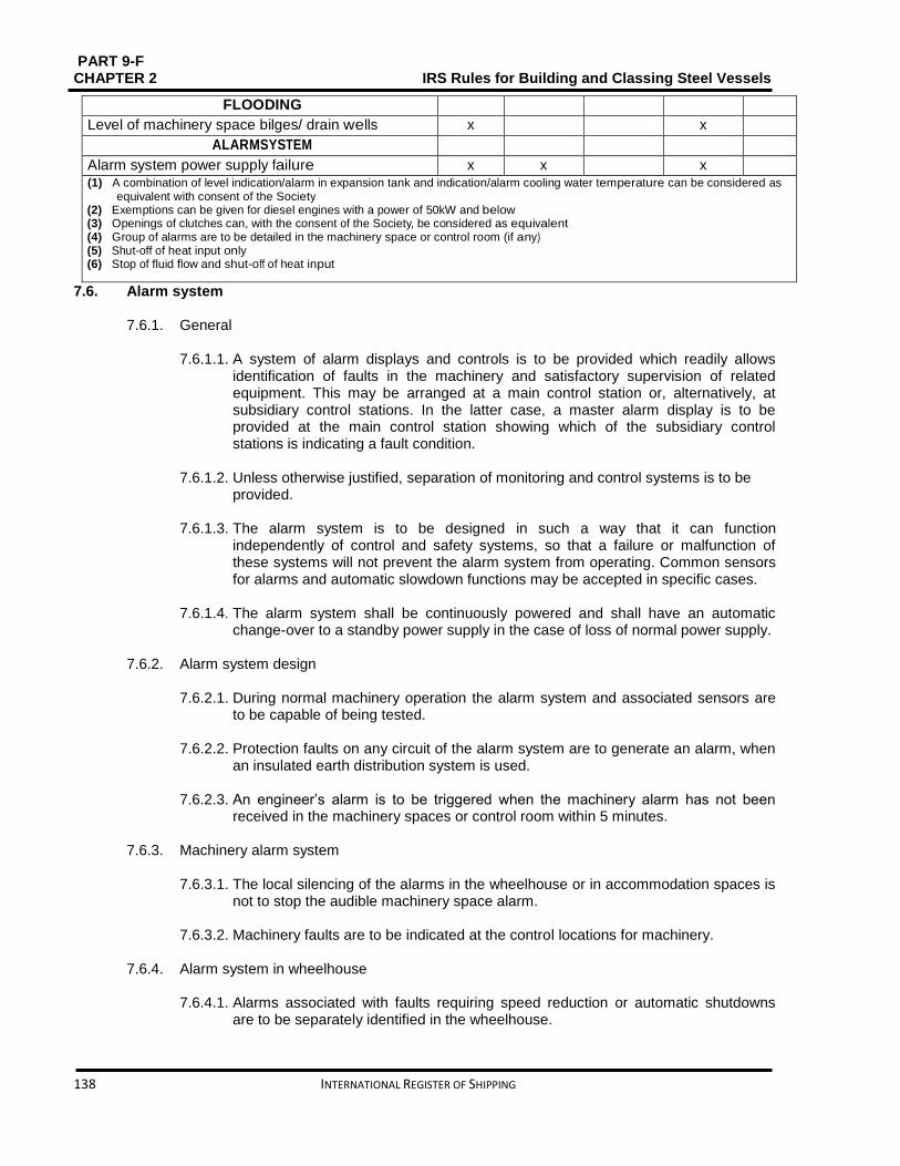
PART 9-F CHAPTER 2 IRS Rules for Building and Classing Steel Vessels
138 INTERNATIONAL REGISTER OF SHIPPING
FLOODING
Level of machinery space bilges/ drain wells x x
ALARMSYSTEM
Alarm system power supply failure x x x (1) A combination of level indication/alarm in expansion tank and indication/alarm cooling water temperature can be considered as
equivalent with consent of the Society (2) Exemptions can be given for diesel engines with a power of 50kW and below (3) Openings of clutches can, with the consent of the Society, be considered as equivalent (4) Group of alarms are to be detailed in the machinery space or control room (if any) (5) Shut-off of heat input only (6) Stop of fluid flow and shut-off of heat input
7.6. Alarm system
7.6.1. General
7.6.1.1. A system of alarm displays and controls is to be provided which readily allows identification of faults in the machinery and satisfactory supervision of related equipment. This may be arranged at a main control station or, alternatively, at subsidiary control stations. In the latter case, a master alarm display is to be provided at the main control station showing which of the subsidiary control stations is indicating a fault condition.
7.6.1.2. Unless otherwise justified, separation of monitoring and control systems is to be
provided. 7.6.1.3. The alarm system is to be designed in such a way that it can function
independently of control and safety systems, so that a failure or malfunction of these systems will not prevent the alarm system from operating. Common sensors for alarms and automatic slowdown functions may be accepted in specific cases.
7.6.1.4. The alarm system shall be continuously powered and shall have an automatic
change-over to a standby power supply in the case of loss of normal power supply.
7.6.2. Alarm system design
7.6.2.1. During normal machinery operation the alarm system and associated sensors are to be capable of being tested.
7.6.2.2. Protection faults on any circuit of the alarm system are to generate an alarm, when an insulated earth distribution system is used.
7.6.2.3. An engineer’s alarm is to be triggered when the machinery alarm has not been
received in the machinery spaces or control room within 5 minutes.
7.6.3. Machinery alarm system
7.6.3.1. The local silencing of the alarms in the wheelhouse or in accommodation spaces is not to stop the audible machinery space alarm.
7.6.3.2. Machinery faults are to be indicated at the control locations for machinery.
7.6.4. Alarm system in wheelhouse
7.6.4.1. Alarms associated with faults requiring speed reduction or automatic shutdowns
are to be separately identified in the wheelhouse.

PART 9 – F IRS Rules for Building and Classing Steel Vessels CHAPTER 2
INTERNATIONAL REGISTER OF SHIPPING 139
7.6.4.2. The alarm system is to activate an audible and visual alarm in the wheelhouse for any situation which requires action by or the attention of the officer on watch.
7.6.4.3. Separable alarms are to be provided in the wheel-house indicating any power
supply failures of the remote control of propulsion machinery. 7.7. Safety system
7.7.1. General
7.7.1.1. Safety systems of different units of the machinery plant are to be autonomous. Failure in the safety system of one part of the plant is not to affect with the operation of the safety system in another part of the plant.
7.7.1.2. The system is to intervene serially in order to avoid adverse disruption in the
operation of machinery, after the operation of the alarm system by:
starting of standby units
Load reduction or shutdown, such that the least drastic action is taken first.
7.7.1.3. The procedure for overriding the shutdown of the main propelling machinery is to
be such as to preclude unintentional operation. 7.7.1.4. The restart is only to be carried out, unless otherwise justified, after setting the
propulsion wheelhouse control level on ”stop” , after stoppage of the propulsion engine by a safety shutdown device.
7.8. Testing
7.8.1. General
7.8.1.1. According to Part 9D, Chapter 14, the tests of automated installations are to be performed to determine their operating conditions. The details of these tests are defined, in each case, after having studied the concept of the automated installations and their construction. A complete test program is to be submitted for approval.

PART 9-F CHAPTER 2 IRS Rules for Building and Classing Steel Vessels
140 INTERNATIONAL REGISTER OF SHIPPING
SECTION 8 GRABLOADING Contents
8.1. General ........................................................................................................................................... 141
8.2. Scantlings ....................................................................................................................................... 141
PART 9 – F IRS Rules for Building and Classing Steel Vessels CHAPTER 2
INTERNATIONAL REGISTER OF SHIPPING 141
8.1. General
8.1.1. Application
8.1.1.1. In accordance with Part 9 A, Chapter 2, Sec 2, [2.3.2.8] the additional class notation Grabloading is allocated, to bulk cargo vessels with holds specially reinforced for loading/unloading cargoes by means of buckets or grabs and complying with the requirements of this Section.
8.2. Scantlings
8.2.1. General In compliance with [8.2.2] and [8.2.3] the net scantlings of plating and structural members within the cargo hold obtained from Chapter 1, Sec 2 is to be increased
8.2.2. Inner bottom
The net scantlings of inner bottom plating and longitudinal, where no continuous wooden ceiling is fitted, obtained from Chapter 1, Sec 2 are to be reinforced as follows:
Inner bottom plating net thickness is to be increased by 2 mm
Inner bottom longitudinal net section modulus is to be increased 1.4 times.
8.2.3. Hold sides and bulkheads
8.2.3.1. The net thicknesses of:
hold side plating up to 1.5 m from the inner bottom
hold bulkhead plating up to 1.5 m from the inner bottom are to be increased by 1.5 mm
8.2.3.2. The net section modulus of:
hold side secondary stiffeners up to 1.5 m from the inner bottom
Hold bulkhead secondary stiffeners up to 1.5 m from the inner bottom is to be increased 1.4 times.
8.2.3.3. The net scantlings of plating and structural members may be tapered to those
obtained from Chapter 1, Sec 2 above 1.5 m from the inner bottom,.
PART 9-F CHAPTER 2 IRS Rules for Building and Classing Steel Vessels
142 INTERNATIONAL REGISTER OF SHIPPING
SECTION 9 POLLUTION PREVENTION (CLEAN VESSEL) Contents
9.1. Scope and application .................................................................................................................... 143
9.2. Definitions and abbreviations ......................................................................................................... 143
9.3. Documents to be submitted and applicable standards .................................................................. 147
9.4. Design requirements for the additional class notation Clean vessel ............................................. 147
9.5. Additional class notation AWT ....................................................................................................... 162
9.6. Additional class notation GWT ....................................................................................................... 163
9.7. Additional class notation NDO-x days ............................................................................................ 164
9.8. Additional class notation NOX-x% ................................................................................................. 165
9.9. Additional class notation OWS-x ppm ............................................................................................ 166
9.10. Additional class notation SOX-x% .............................................................................................. 166
9.11. Onboard Surveys........................................................................................................................ 167

PART 9 – F IRS Rules for Building and Classing Steel Vessels CHAPTER 2
INTERNATIONAL REGISTER OF SHIPPING 143
9.1. Scope and application
9.1.1. General
9.1.1.1. This Section covers the requirements for the prevention of water and air pollution. 9.1.1.2. Additional class notations for the prevention of water and air pollution include:
Clean vessel
Other notations having a specific scope.
The appropriate symbol, scope, reference to the Rules and assignment conditions are given in Table 2.9.1. Examples of notations are given below:
Cleanvessel
OWS-5 ppm
AWT, NDO-2 days
9.1.1.3. Requirements for onboard surveys are given in Part A.
9.1.2. Applicable rules and regulations
9.1.2.1. The vessel flag Authorities and/or by the State or Port Administration Added requirements may be imposed in the jurisdiction of which the vessel is intended to operate, in particular with respect to:
Exhaust gas smoke (particulate emissions, smoke opacity)
Fuel oil sulphur content
Bilge water oil content
On board waste incineration
9.2. Definitions and abbreviations
9.2.1. Definitions related to water pollution 9.2.1.1. Hazardous wastes
Hazardous wastes are those wastes composed of materials which are identified as water pollutants in the European Agreement concerning the International Carriage of Dangerous Goods (ADN).
Hazardous wastes include in particular:
photo processing chemicals
dry cleaning waste
used paints
solvents
heavy metals
expired chemicals and pharmaceuticals
waste from printers
hydrocarbons and chlorinated hydrocarbons
used fluorescent and mercury vapour light bulbs
batteries
Note 1: Empty packagings previously used for the carriage of hazardous substances are to be considered as hazardous substances.

PART 9-F CHAPTER 2 IRS Rules for Building and Classing Steel Vessels
144 INTERNATIONAL REGISTER OF SHIPPING
9.2.1.2. Wastewater
Wastewater includes both sewage and grey water defined hereunder.
Table 2.9.1: Additional class notations for the prevention of pollution
9.2.1.3. Sewage
Sewage means:
drainage and other wastes from any form of toilets, urinals, and WC scuppers, here designated as black waters
drainage from medical premises (dispensary, sick bay, etc.) via wash basins, wash tubs and scuppers located in such premises
drainage from spaces containing live animals, or
Other waste waters when mixed with the drainages defined above.
9.2.1.4. Sewage sludge Sewage sludge means any solid, semi-solid, or liquid residue removed during the treatment of on-board sewage.
9.2.1.5. Grey water Grey water includes drainage from dishwashers, showers, sinks, baths and washbasins, laundry and galleys.
9.2.1.6. Garbage
Garbage means all kinds of victual, domestic and operational waste excluding fresh fish and parts thereof, produced during the normal operation of the vessel.
Symbol Scope Reference to the Sections in Chapter 2
Assignment conditions
Clean vessel
Prevention of river and air pollution [2.4]
AWT Fitting of an Advanced Waste water Treatment plant
[2.5]
GWT Fitting of a treatment installation for Grey Waters
[2.6]
NDO-x days
The vessel is designed for No Discharge Opera-tion during x days
[2.7]
NOX-x% Average NOx emissions of engines not exceed-ing x% of limit
[2.8]
OWS-x ppm
Fitting of an Oily Water Separator producing effluents having a hydrocarbon content not exceeding x ppm (parts per million)
[2.9]
SOX-x% Oil fuels have a sulphur content not exceeding x% of the relevant limit
[2.10]
As an alternative, equivalent arrange- ments (e.g. exhaust gas cleaning systems)may be accepted

PART 9 – F IRS Rules for Building and Classing Steel Vessels CHAPTER 2
INTERNATIONAL REGISTER OF SHIPPING 145
Garbage includes all kinds of solid wastes like plastics, paper, oily rags, glass, metal, bottles, and incinerator ash. Food wastes are considered as garbage.
9.2.1.7. Oil residue (sludge)
Oil residue (sludge) means the residual waste oil products generated during the normal operation of a vessel such as those resulting from the purification of fuel or lubricating oil for main or auxiliary machinery, separated waste oil from oil filtering equipment, waste oil collected in drip trays, and waste hydraulic and lubricating oils.
9.2.1.8. Oil residue (sludge) tank
Oil residue (sludge) tank means a tank which holds oil residue (sludge) from which sludge may be disposed directly through the standard discharge connection or any other approved means of disposal.
9.2.1.9. Oily bilge water
Oily bilge water means water which may be polluted by oil resulting from things such as leakage or maintenance work in machinery spaces. Any liquid entering the bilge system including bilge wells, bilge piping, tank top or bilge holding tanks is considered oily bilge water.
9.2.1.10. Oily bilge water holding tank
Oily bilge water holding tank means a tank collecting oily bilge water prior to its
discharge, transfer.
9.2.1.11. Oily wastes Oily wastes mean oil residues (sludge) and oily bilge water.
9.2.1.12. Advanced Wastewater Treatment (AWT) The treatment of wastewater is known which goes beyond the secondary or biological water treatment stage and includes the removal of nutrients such as phosphorus and nitrogen and a high percentage of suspended solids. AWT water discharge standard corresponds to the technology currently available for municipal wastewater treatment plants.
9.2.1.13. Accidental discharge
All discharge to water caused by unforeseen or accidental events, such as damage to the vessel or its equipment, and including discharge necessary for the purpose of protection of the vessel or saving life.
9.2.1.14. No discharge condition Condition without discharge of hazardous wastes, treated and untreated wastewater, oily wastes or garbage into the water is known as “No discharge condition”. Note 1: Where the AWT notation is allocated to the vessel, the discharge of treated sewage and treated grey water is allowed.
Note 2: In the “No discharge condition”, no effluents from exhaust gas cleaning systems may be discharged into the water.

PART 9-F CHAPTER 2 IRS Rules for Building and Classing Steel Vessels
146 INTERNATIONAL REGISTER OF SHIPPING
9.2.2. Definitions related to air pollution
9.2.2.1. Emission
Emission means any release of substances from vessels into the atmosphere or water.
9.2.2.2. Ozone depleting substances 9.2.2.3. Ozone-depleting substances means controlled substances well-defined in
paragraph (4) of article 1 of the Montreal Protocol on Substances that Deplete the Ozone Layer, 1987, listed in Annexes A, B, C or E to the said protocol in force.
Ozone-depleting substances that may be found on board vessel contain, but are not limited to:
Halon 1211Bromochlorodifluoromethane
Halon 1301Bromotrifluoromethane
Halon 2402 1,2-Dibromo-1,1,2,2-tetrafluoroethane(also known as Halon 114B2)
CFC-11 Trichlorofluoromethane
CFC-12 Dichlorodifluoromethane
CFC-113 Trichloro-1,2,2-trifluoroethane
CFC-114 1,2-Dichloro-1,1,2,2-tetrafluoroethane
CFC-115 Chloropentafluoroethane.
9.2.2.4. Onboard incineration Onboard incineration means the incineration of wastes or other matter on board a vessel, if such wastes or other matter were produced during normal operation of that vessel.
9.2.2.5. Onboard incinerator
Onboard incinerator means an onboard facility considered for the primary purpose of incineration.
9.2.2.6. Exhaust gas smoke
Exhaust gas smoke is a visible suspension of solid and/or liquid particles in gases resulting from combustion or pyrolysis.
Note 1:
Black smoke (soot) is mainly comprised of carbon particles
blue smoke is usually due to droplets resulting from the incomplete combustion of fuel or lubricating oil
white smoke is usually due to condensed water and/or liquid fuel
yellow smoke is caused by NO2
9.2.3. Abbreviations
9.2.3.1. AWT AWT means advanced wastewater treatment.
9.2.3.2. EGC
EGC means exhaust gas cleaning.

PART 9 – F IRS Rules for Building and Classing Steel Vessels CHAPTER 2
INTERNATIONAL REGISTER OF SHIPPING 147
9.2.3.3. OWS OWS means oily water separator.
9.3. Documents to be submitted and applicable standards
9.3.1. Documents to be submitted
9.3.1.1. Certificates The certificates to be submitted prior to the delivery of the additional class notations Clean vessel and other notations are listed in Table 2.9.2.
9.3.1.2. Operational procedures
The operational procedures to be submitted are listed in Table 2.9.3.
9.3.1.3. Plans and documents
The plans and documents to be submitted are listed in Table 2.9.44.
9.3.2. Modifications and additions
9.3.2.1. The relevant details are to be submitted for review/approval in case of
modifications or additions to the approved installations, arrangements or procedures.
9.4. Design requirements for the additional class notation Clean vessel
9.4.1. Waste management
9.4.4.1. Waste generation
The waste quantities to be considered for the calculation of:
The volume of the holding tanks
The capacity of the waste treatment and storage equipment are to be derived from the experience gained on similar types of vessels operated in similar conditions. Where no data are available, the figures listed in Table 2.9.5 are to be used.

PART 9-F CHAPTER 2 IRS Rules for Building and Classing Steel Vessels
148 INTERNATIONAL REGISTER OF SHIPPING
Table 2.9.2: Required certificates
Notations
Certificate Applicable Rules and Regulations
Cleanvessel
Type approval certificate of these wage system
IMOResolutionMEPC.159(55)
Type approval certificate of the incinerator (1)
• IMO Resolution MEPC.76(40) as amended by Resolution
MAPC.93(45) • AnnexVIofMARPOL73/78,Appendix IV
Type approval certificate for new engines (2)
Sox emission compliance certificate Certificate of unit approval for exhaust gas cleaning system (3)
IMO Resolution MEPC.184 (59), Appendix I
IAFS certificate or Declaration on Anti-fouling system
International Convention on the control of Harmful and Anti-fouling systems, 2001, Annex 4, Appendices 1 and 2
AWT Type approval of the AWT plant [2.5]
GWT Type approval certificate of the grey water treatment plant
[2.6]
NDO-x days
N/R
NOX-x% Type approval certificate for new engines (2)
[2.8]
OWS-x ppm
Type approval certificate of the oily water sep-arator with indication of “x ppm” performance
[2.9]
SOX-x% Type approval certificate of the exhaust gas cleaning system (3)
[2.10]
(1) Onboard incinerator is not required. However, when fitted onboard, it is to be type-approved. (2) Type approval certificate may include a NOx-reducing device as a component of the engine. (3) Where such an equivalent arrangement is provided. Note1:N/R=not required

PART 9 – F IRS Rules for Building and Classing Steel Vessels CHAPTER 2
INTERNATIONAL REGISTER OF SHIPPING 149
Table 2.9.3: Required operational procedures
Notations Operational procedure Applicable Rules and Regulations Clean vessel Onboard oil pollution plan IMO Resolution MEPC.54(32) as
amended by Resolution MEPC.86(44)
Procedure to prepare and maintain an oil record book
−
Bunkering procedure −
Measures to prevent oil pollution −
Sewage and grey water management plan and discharge control plan
IMO ResolutionMEPC.157(55)
Garbage management plan including procedures to prepare and maintain a garbage record book and hazardous waste procedures
• IMO ResolutionMEPC.70(38) • IMO Circular MEPC/Circ.317 • IMO ResolutionMEPC.92(45)
Operating procedure to be followed to minimize the risk and the consequences of ozone-depleting refrigerant leakage, under normal and emergency conditions, including (1): • checking of the piping tightness • recharge • detection of leakage • maintenance and repair
−
Procedure to prepare and maintain the ozone-depleting sub-stances record book (1)
−
NOx emission control plan −
Fuel oil quality management plan IMOResolutionMEPC.182(59)
Where an exhaust gas cleaning (EGC) system is used: • Sox emission compliance plan • Onboard monitoring manual • Procedure to prepare and maintain the EGC record book
IMOResolutionMEPC.184(59)
AWT Waste water management plan and discharge control plan
−
GWT Grey water management plan and discharge control plan
−
NDO-xdays Management and storage plan for liquid effluents and solid waste in case of no-discharge operation
−
NOX-x% NOx emissions control plan −
OWS-xppm Performance monitoring plan for the oily water separator
−
SOX-x% Sox emissions control plan −
(1) Only where ozone-depleting substances are used onboard.
9.4.4.2. Separation of waste streams
Design arrangements and procedures for collecting, sorting, treating, storing and discharging solid and liquid waste and harmful substances are to be such that the discharge or discharge prohibition criteria can be fulfilled.

PART 9-F CHAPTER 2 IRS Rules for Building and Classing Steel Vessels
150 INTERNATIONAL REGISTER OF SHIPPING
Generally, this implies that the following categories of wastes are separated before any treatment or storage:
products containing hazardous substance, as defined in[9.2.1.1]
plastics, which have to be separated from wastes ultimately discharged to river (sewage or food wastes for instance)
sewage, including drainage from medical premises, which has to be collected separately from grey water, except if a common treatment installation is installed on board.
Note 1: This does not preclude the mixing of effluents after treatment (e.g. treated sewage mixed with grey water) Note 2: When water is mixed with wastewater (e.g. for the purpose of washing the holding tanks), the discharge requirements for the waste water apply to the resulting mixture. Note 3: When categories of wastewater having different discharge requirements are mixed together, the most stringent requirements apply to the resulting mixture.
9.4.4.3. Incineration
Although incineration is possible, storage and subsequent discharge to port reception facilities is to be given first priority. Except otherwise stated here, storage arrangements are to be provided for all kinds of liquid and solid wastes, with a capacity corresponding to one day operation of the vessel. Note 1: The attention is drawn to the specific requirements imposed by certain flag Authorities and / or State or Port Administration, which may restrict or prohibit waste discharge and/or incineration in the waters under their jurisdiction.

PART 9 – F IRS Rules for Building and Classing Steel Vessels CHAPTER 2
INTERNATIONAL REGISTER OF SHIPPING 151
Table 2.9.4: Required plans and documents
Notation Documents Approval status
Cleanvessel General: • general arrangement plan with indication of the waste collection and
conveying circuits, storage means and treatment installations intended for the prevention of pollution by oil, sewage, grey waters, garbage and hazardous packaged substances
• capacity plan • program for a waste source reduction, minimization and recycling
I
I A
Prevention of pollution by oil: • diagram of the oil residue (sludge)system, • diagram of the independent clean drain system, where provided • diagram of the oily bilge system (pumping, treatment, discharge) • details of the bilge water holding tank • calculation of the bilge water holding tank capacity
I II A
A
Prevention of pollution by sewage and waste water: • diagram of the grey water system (collection, treatment, discharge) • diagram of these wage system (collection, treatment, discharge) • details of these wage holding tank and grey water holding tank • calculation of these wage holding tank and grey water holding tank capacity • description of these wage treatment plant or comminuting/disinfecting system
I IA A I
Prevention of pollution by garbage: • general information on the equipment intended for collecting,
storing, processing and disposing of garbage (except where type-approved)
• calculation of the necessary storing, processing and disposing capacities • diagram of control and monitoring systems for garbage handling equipment
I A
A
Prevention of pollution by oil spillage and leakage: • diagram of the fuel oil and lubricating oil overflow systems • diagramofthefueloilandlubricatingoilfilling,transferandventingsystems • arrangement of the fuel oil and lubricating oil spillage containment systems • diagram of the control and monitoring system for fuel oil filling, transfer
and overflow systems • diagram of the stern tube lubricating oil system
A I A I
A
Prevention of oil pollution in case of collision or stranding: • arrangement of the fuel oil tanks , lubricating oil tanks and sludge tanks
with indication of the volume and of the distance between the tank and the vessel baseline/vessel shell side
I
Prevention of pollution by anti-fouling systems: • specification of antifouling paint
A

PART 9-F CHAPTER 2 IRS Rules for Building and Classing Steel Vessels
152 INTERNATIONAL REGISTER OF SHIPPING
AWT • diagram of the grey water system (collection, treatment, discharge) • diagram of the sewage system (collection, treatment, discharge) • details of the sewage holding tank and grey water holding tank • calculation of these wage holding tank and grey water holding tank capacity • description of the Advanced Waste water Treatment (AWT) plant and
relevant operating principles
I IA AI
GWT • diagram of the grey water system (collection, treatment, discharge) • details of the grey water holding tank • calculation of the grey water holding tank capacity • description of the grey water treatment plant and relevant operating principles
I A A I
NDO-xdays Calculation of the storage capacity for solid wastes and liquid effluents A
NOX-x% • calculation of the weighted average NOx emission level of the vessel • calculation of the weighted average NOx emission limit of the vessel
A A
OWS-xppm Description of the OWS plant and relevant operating principles I
SOX-x% Where low sulphur fuel oils are used: • diagram of the fuel oil supply systems • change-over procedure Where an exhaust gas cleaning system is fitted: • wash water diagram • description of the system and relevant operating principles
I I
A I
Note1: I =to be submitted for information A =to be submitted for approval
A/I=to be submitted for approval or information, in accordance with the relevant Rules or Rule Note. Note2: Diagrams are to include information about monitoring and recording of parameters.
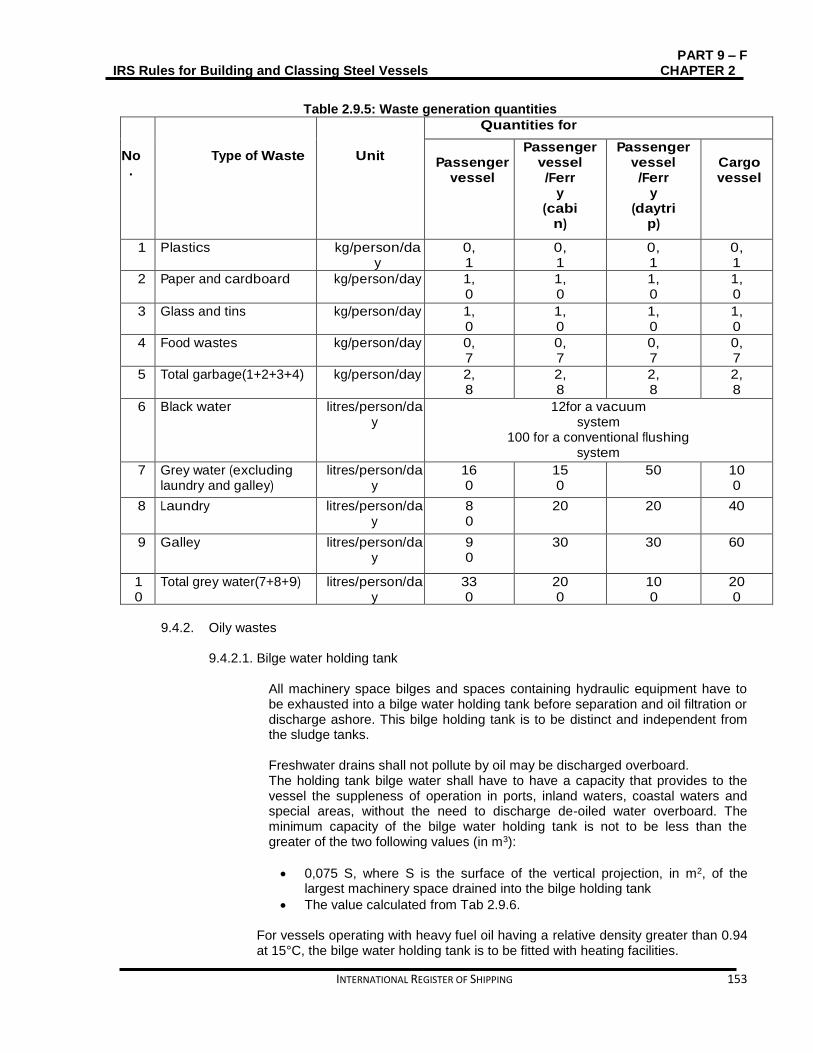
PART 9 – F IRS Rules for Building and Classing Steel Vessels CHAPTER 2
INTERNATIONAL REGISTER OF SHIPPING 153
Table 2.9.5: Waste generation quantities
No.
Type of Waste
Unit
Quantities for
Passenger
vessel
Passenger vessel /Ferr
y (cabi
n)
Passenger vessel /Ferr
y (daytri
p)
Cargo vessel
1 Plastics kg/person/day
0,1
0,1
0,1
0,1
2 Paper and cardboard kg/person/day 1,0
1,0
1,0
1,0
3 Glass and tins kg/person/day 1,0
1,0
1,0
1,0
4 Food wastes kg/person/day 0,7
0,7
0,7
0,7
5 Total garbage(1+2+3+4) kg/person/day 2,8
2,8
2,8
2,8
6 Black water litres/person/day
12for a vacuum system
100 for a conventional flushing system
7 Grey water (excluding laundry and galley)
litres/person/day
160
150
50 100
8 Laundry litres/person/day
80
20 20 40
9 Galley litres/person/day
90
30 30 60
10
Total grey water(7+8+9) litres/person/day
330
200
100
200
9.4.2. Oily wastes
9.4.2.1. Bilge water holding tank
All machinery space bilges and spaces containing hydraulic equipment have to be exhausted into a bilge water holding tank before separation and oil filtration or discharge ashore. This bilge holding tank is to be distinct and independent from the sludge tanks. Freshwater drains shall not pollute by oil may be discharged overboard. The holding tank bilge water shall have to have a capacity that provides to the vessel the suppleness of operation in ports, inland waters, coastal waters and special areas, without the need to discharge de-oiled water overboard. The minimum capacity of the bilge water holding tank is not to be less than the greater of the two following values (in m3):
0,075 S, where S is the surface of the vertical projection, in m2, of the largest machinery space drained into the bilge holding tank
The value calculated from Tab 2.9.6.
For vessels operating with heavy fuel oil having a relative density greater than 0.94 at 15°C, the bilge water holding tank is to be fitted with heating facilities.
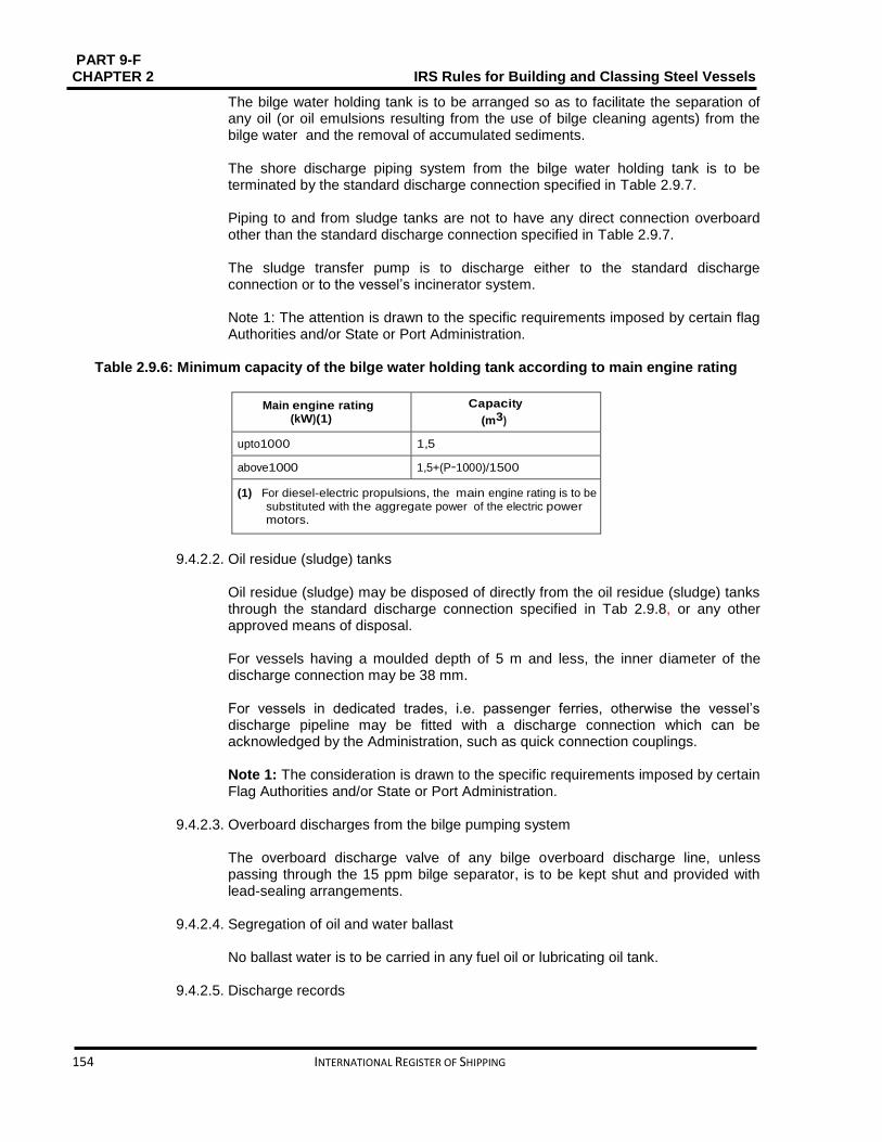
PART 9-F CHAPTER 2 IRS Rules for Building and Classing Steel Vessels
154 INTERNATIONAL REGISTER OF SHIPPING
The bilge water holding tank is to be arranged so as to facilitate the separation of any oil (or oil emulsions resulting from the use of bilge cleaning agents) from the bilge water and the removal of accumulated sediments. The shore discharge piping system from the bilge water holding tank is to be terminated by the standard discharge connection specified in Table 2.9.7. Piping to and from sludge tanks are not to have any direct connection overboard other than the standard discharge connection specified in Table 2.9.7. The sludge transfer pump is to discharge either to the standard discharge connection or to the vessel’s incinerator system. Note 1: The attention is drawn to the specific requirements imposed by certain flag Authorities and/or State or Port Administration.
Table 2.9.6: Minimum capacity of the bilge water holding tank according to main engine rating
Main engine rating (kW)(1)
Capacity
(m3)
upto1000 1,5
above1000 1,5+(P−1000)/1500
(1) For diesel-electric propulsions, the main engine rating is to be substituted with the aggregate power of the electric power motors.
9.4.2.2. Oil residue (sludge) tanks
Oil residue (sludge) may be disposed of directly from the oil residue (sludge) tanks through the standard discharge connection specified in Tab 2.9.8, or any other approved means of disposal. For vessels having a moulded depth of 5 m and less, the inner diameter of the discharge connection may be 38 mm. For vessels in dedicated trades, i.e. passenger ferries, otherwise the vessel’s discharge pipeline may be fitted with a discharge connection which can be acknowledged by the Administration, such as quick connection couplings. Note 1: The consideration is drawn to the specific requirements imposed by certain Flag Authorities and/or State or Port Administration.
9.4.2.3. Overboard discharges from the bilge pumping system The overboard discharge valve of any bilge overboard discharge line, unless passing through the 15 ppm bilge separator, is to be kept shut and provided with lead-sealing arrangements.
9.4.2.4. Segregation of oil and water ballast No ballast water is to be carried in any fuel oil or lubricating oil tank.
9.4.2.5. Discharge records

PART 9 – F IRS Rules for Building and Classing Steel Vessels CHAPTER 2
INTERNATIONAL REGISTER OF SHIPPING 155
Requirements are to be made to record the following parameters related to the oily water discharge:
date and time of the discharge
vessel location
quantity and oil content of oily water discharged.
Table 2.9.7: Standard dimensions of flangers for discharge connection
Description Dimension
Outside diameter 215mm
Inner diameter According to pipe outside diameter
Bolt circle diameter 183mm
Slots in flange 6 holes 22 mm in diameter equidistantly placed on a bolt circle of above diameter, slotted to the flange periphery. The slot width to be 22mm.
Flange thickness 20mm
Bolts and nuts: quantity, diameter
6,each 20 mm in diameter and of suitable length
Note 1: The flange is designed to accept pipes up to a maximum internal diameter of 125 mm and shall be of steel or other equivalent material having a flat face. This flange, together with a gasket of oil-proof material, shall be suitable for a service pressure of 600 kPa.
Table 2.9.8: Standard dimensions of flanges for discharge connection
Description Dimension
Outside diameter 210 mm
Inner diameter According to pipe outside diameter
Bolt circle diameter 170 mm
Slots in flange 4 holes18 mm in diameter equidistantly placed on a bolt circle of above diameter, slotted to the flange periphery. The slot width to be 18mm.
Flange thickness 16mm
Bolts and nuts: quantity, diameter
4,each16mm in diameter and of suitable length
Note1:The flange is designed to accept pipes up to a maximum internal diameter of100 mm and shall be of steel or other equivalent material having a flat face. This flange, together with a gasket of oil-proof material, shall be suitable for a service pressure of 600 kPa.
9.4.3. Wastewaters
9.4.3.1. The vessel is to be fitted with a sewage and a grey water system intended and
arranged as follows:
An approved sewage treatment plant or sewage comminuting and disinfecting system is to be provided.
A tank is to be provided for the storage of untreated or treated sewage with a capacity complying with [9.4.3.2].
A tank is to be provided for the storage of grey waters with a capacity complying with [9.4.3.2].
Grey water from galleys is to be collected separately from other grey waters and led through a grease trap prior to other treatment, storage or discharge.
PART 9-F CHAPTER 2 IRS Rules for Building and Classing Steel Vessels
156 INTERNATIONAL REGISTER OF SHIPPING
Note 1: Treated sewage and grey water holding tanks may be combined together.
9.4.3.2. Holding tanks Holding tanks for sewage and grey water are to have a size sufficient for 24 hours operation of the vessel, having regard to the maximum number of persons on board, the daily making of wastewater given in Table 2.9.5 and other appropriate factors. The holding tanks are to be competently secured against corrosion and fitted with a level indicator and a high level alarm.
9.4.3.3. Sewage treatment plants and piping In accordance with the provisions of IMO Resolution MEPC 159(55) sewage treatment plants are to be of a type approved. Necessities are to be made in the design for easy access points for the purpose of obtaining representative influent and effluent samples. Plastic garbage is to be detached from sewage and/or grey water before entering the treatment unit.
9.4.3.4. Sewage sludges Sludges from sewage treatment are to be collected and stored then discharged ashore or, where permitted, incinerated onboard. Where provided, incineration devices are to completely burn the sludges to a dry and inert ash and not to discharge fly ash, malodors or toxic substances. The capacity of the sewage sludge tanks is to be calculated taking into consideration:
the maximum period of voyage between ports where sludge can be discharged ashore, or
The incinerator capacity and whether incineration is per-mitted in the areas where the vessel is intended to operate. In the absence of precise data, a figure of 30 days is to be used.
Ashes from sludge incineration are to be disposed ashore except where permitted under [9.4.4.6].
9.4.3.5. Discharge records Provisions are to be made to record the following parameters related to the sewage and grey water discharge:
Date and time of discharge
Position of the vessel
Quantity of sewage or grey water discharged
Quantity of sludges incinerated or discharged ashore.

PART 9 – F IRS Rules for Building and Classing Steel Vessels CHAPTER 2
INTERNATIONAL REGISTER OF SHIPPING 157
9.4.4. Garbage and hazardous wastes
9.4.4.1. Garbage management plan In the garbage management plan procedures for collection, sorting, processing and disposal of garbage shall be available. The garbage management plan is to include actions in order to make sure that the following hazardous wastes are not mixed with other waste streams:
Photo processing waste (including X-ray development fluid waste)
Dry cleaning waste, containing in particular Tetrachloroethylene or Perchloroethylene (PERC)
Printing materials, like inks, except soy based, non-chlorinated hydrocarbon based ink products
Laser printer toner cartridges
Unused and outdated pharmaceuticals
Fluorescent / mercury vapour bulbs batteries
Used cleaners, solvents, paints and thinners
Products containing metals such as lead, chromium, copper, cadmium and mercury.
9.4.4.2. Handling of hazardous waste
Prior to disposal ashore, hazardous wastes are to be collected and stored in distinct leak proof containers. The storage capacity is to be sufficient for the average production of 30 days. The contents of all containers are to be clearly marked. Note 1: Waste fluids associated with photo processing, including X-ray development, may be treated to remove silver for recycling. The effluent from the recovery unit may be led to the grey water provided it contains less than 5 part per million (ppm). The residues from the recovery unit are to be landed ashore for disposal or recycling.
9.4.4.3. Collection of garbage
Garbage bins are to be placed at suitable places and within a suitable distance in accommodation spaces and open decks. Hazardous wastes, plastics and food contaminated wastes are to be collected separately from other wastes.
9.4.4.4. Storage of garbage Taking into account the daily waste generation figures given in [9.4.1.1] and the values of density given in Table 2.9.1, the vessel is to have sufficient capacity to store all kinds of garbage produced during one day,. If burning is permitted in the areas where the vessel is planned to operate, the needed capacity for wastes other than glass and tins may be reduced by 40%, without being less than the needed volume corresponding to one day.
Table 2.9.9: Waste density
Type of waste Density (kg/m3)
compacted waste
Un compacted waste
Glass, tin 1600 160
Paper, cardboard, plastic 410 40

PART 9-F CHAPTER 2 IRS Rules for Building and Classing Steel Vessels
158 INTERNATIONAL REGISTER OF SHIPPING
9.4.4.5. Food wastes
According to IRS arrangements are to be made to store food wastes prior to discharge to port reception facilities. Taking into account the figures given in [9.4.1.1] the onboard storage capacity is to be sufficient for one day food waste production. Food wastes and wastes polluted with food are to be stored in high integrity sealed packaging and refrigerated to 5°C.
9.4.4.6. Incinerators Incinerators are to be type-approved by the Society, where fitted, designed and constructed according to the requirements of MEPC.76 (40), as amended by MEPC. 93(45) Proper hazardous waste management procedures including separating hazardous wastes should be introduced onboard each vessel to assure hazardous wastes are not acquainted with into the incinerator. Particularly, batteries should be removed from any waste that will be incinerated onboard. Ashes containing toxic or heavy metal residues are to be kept on board in a proper container and landed ashore for disposal. Other ashes may be discharged at river where per-mitted. Note 1: Ashes are considered as free from toxic or heavy metal residues when metal analysis show that the limit concentrations given in Tab 10 are not exceeded.
Table 2.9.10: Limit concentrations of toxic and heavy metals substances in ashes
Substance Limit concentration(ppm)
Arsenic 0,3
Barium 4,0
Cadmium 0,3
Chromium 5,0
Lead 1,5
Mercury 0,01
Selenium 0,3
Silver 0,2
9.4.4.7. Discharge records
Provisions are to be made to record the following parameters related to the garbage discharge:
Date and time of discharge
Vessel location (latitude and longitude) or location of ashore discharge facilities
Estimated amounts discharged for each category, including incinerator ash (in cubic meters).
9.4.5. Hull antifouling systems
9.4.5.1. Compliance with IMO AFS Convention
Vessels granted with the additional class notation, clean vessel have to comply with the relevant requirements of IMO Convention on the Control of Harmful Anti-
PART 9 – F IRS Rules for Building and Classing Steel Vessels CHAPTER 2
INTERNATIONAL REGISTER OF SHIPPING 159
fouling Systems on vessels, 2001, requiring the complete prevention of organotin compounds which act as biocides in anti-fouling systems.
9.4.5.2. Type-approval of anti-fouling systems
The Society must approve the anti-fouling paints on the basis of the following criteria:
The product is to be TBT-free
Small quantities of organotin compounds acting as chemical catalysts are acceptable only if their concentration does not exceed 2500 mg total tin per kg of dry paint.
9.4.6. Prevention of pollution by oil spillage and leakage
9.4.6.1. Overflow systems
All fuel and lubricating oil tanks with the capacity of which exceeds 10 m3 are needed to be fitted with an overflow system and a high level alarm or a flow alarm in the overflow system. The alarm signal is to be specified where the person in charge of the bunkering or transfer operation will normally be located.
9.4.6.2. Containment systems
On the weather and superstructure decks, each fuel or lubricating oil tank vent, overflow and fill pipe connection and each other area where oil spillage may occur is to be fitted with a fixed deck container or enclosed deck area with a capacity of:
80 litres if the gross tonnage of the vessel is between 300 and 1600
160 litres if the gross tonnage of the vessel is greater than 1600.
The deck container or area is to be sitted with a closed drainage system. A seven-barrel spill kit containing the following is to be available on board, ready to be used during bunkering operation:
Sorbents sufficient to absorb seven barrels of oil
Non-sparking hand scoops, shovels and buckets
Portable containers suitable for holding seven barrels of recovered solid waste and seven barrels of recovered liquid waste
A minimum of 60 litres of a deck cleaning agent
Appropriate protective clothing to protect personnel from inhalation hazards, eye exposure and skin contact
Non-sparking portable pumps with appropriate hoses.
9.4.6.3. Stern tube leakage Tailshafts providing with oil lubricated bearings are needed to be fitted with type approved oil sealing glands. In accordance with recognized standards the sealing glands are needed to be provided with an oil leak prevention air seal or the stern tube oil is to be of a non-toxic and decomposable quality approved. The oil tanks are to be fitted with a level sensor giving an alarm in case of low level. Arrangements are to be made to record the level of those tanks. All oil filling or topping up operations are to be recorded.
9.4.6.4. Oil detection in cooling water circuits Hydrocarbon detectors are to be provided in river water and fresh water cooling systems including fuel oil or lubricating oil heat exchangers in order to detect any pollution of the water.
PART 9-F CHAPTER 2 IRS Rules for Building and Classing Steel Vessels
160 INTERNATIONAL REGISTER OF SHIPPING
9.4.6.5. Oily condensates from venting pipes
Venting pipes from machinery spaces and containing hydrocarbon vapours are to be directed to a venting box provided with a draining pipe associated to a suitable oily drain tank.
9.4.7. Refrigeration systems
9.4.7.1. Application
The following requirements relate to the vessel centralized refrigerating plants, centralized air conditioning plants and gas reliquefaction plants. They do not apply to the refrigeration facilities planned for the storage of the galley supplies and to the air conditioning plants for limited parts of the vessel, such as the control rooms and the wheelhouse.
9.4.7.2. Acceptable refrigerants The use of halogenated substances as refrigerant is banned, with the exception of hydro chlorofluorocarbons (HCFCs), which are permitted until 1 January 2020.
9.4.7.3. Retention facilities Refrigeration systems are to be built-in with retention facilities having the proficiency to retain all the refrigerants and in case of necessity or an emergency to evacuate the whole plant. The retention facilities may be tanks for liquid media and/or bottles for gaseous media. One or more compressors having the combined capacity to discharge completely the medium from the system into the tanks are to be installed if only tanks for liquid are used as retention facilities.
9.4.7.4. Prevention of leakage Refrigeration systems are to be built in such a way as to reduce the risk of medium release in the case of maintenance, repair or servicing. Arrangements are to be made to separate those sections which are to be serviced by a system of valves and by-passes, in such a way as not to stop the operation of the plant, while in service, preventing the risk of release of the medium outside of the plant. Means are to be provided to avoid the possibility of leak to the atmosphere of the refrigerants or its vapours in any case of failure of the plant. A warning instruction plate asserting that deliberate emissions of halogenated substances is prohibited is to be displayed in the surrounding area of the vessels and of the releasing devices.
9.4.7.5. Leak detection
Appropriate and IRS approved leak detectors shall continuously monitor the spaces where the medium might be likely to leak.
9.4.7.6. Alarm Any finding of medium leak is to initiate an audible and visible alarm in a normally manned location. The alarm is to be activated when the concentration of refrigerating or fire extinguishing medium reaches a value agreed with the Society on a case by case basis.

PART 9 – F IRS Rules for Building and Classing Steel Vessels CHAPTER 2
INTERNATIONAL REGISTER OF SHIPPING 161
9.4.8. Fire-fighting systems
9.4.8.1. Acceptable fire-fighting media The use of halon and halocarbons media in the fixed and portable firefighting equipment is prohibited.
9.4.8.2. Design requirements for fire-fighting systems
Provisions are to be made for the safe containment and disposal of fire-fighting media in case of spillage during maintenance or repair.
9.4.9. Emission of nitrogen oxides (NOx)
9.4.9.1. Application The following requirements apply to all diesel engines, independently of the service, with a rated power of more than 130 kW, installed on the vessel, with the exceptions of:
Emergency diesel engines, diesel engines installed in life boats and any other diesel engines intended to be used solely in an emergency situation, independently of their rated power
Engines which are subject to alternative measures for limiting NOx emission, under special consideration of the Society.
Note 1: NOx emissions from gas only engines, gas turbines, boilers and incinerators are not subject to these requirements.
9.4.9.2. NOx certification of engines Aforementioned to installation onboard the vessel, new engines have to be NOx-certified in accordance with the relevant provisions of the NOx limit for the intended application. The Society Normally issued a valid type approval certificate (or statement of compliance).
9.4.9.3. NOx reduction methods Water injection, fuel oil emulsification, charge air humidification, exhaust as after-treatment which are known as NOx reduction methods where used, the Society must approve that and taken into account in the type approval certificate of the engine. The measurement of NOx emission levels, where required for the control of the reduction process (e.g. to adjust the injection rate of the reduction agent for SCR systems), is to be carried out by means of type-approved analysers.
9.4.10. Emission of sulphur oxides (SOx)
9.4.10.1. Use of low sulphur fuel oils Arrangements are to be made to record the following parameters:
Volume of fuel oil in each tank
Date, time and position of the vessel when the fuel change-over operation is completed or started.
9.4.10.2. Use of exhaust gas cleaning systems Accordance to IMO Resolution MEPC 184(59): 2009 Guidelines for exhaust gas cleaning systems, (EGC) systems, which may be accepted as an arrangement equivalent to the use of low sulphur fuel oils, are to be approved.
PART 9-F CHAPTER 2 IRS Rules for Building and Classing Steel Vessels
162 INTERNATIONAL REGISTER OF SHIPPING
In accordance with the aforesaid Resolution EGC systems are to be fitted with data measuring, recording and processing devices.
The discharge wash water is to satisfy the criteria given in the aforesaid Resolution. Wash water treatment residues generated by the EGC unit are to be stored in a holding tank having a capacity sufficient for 30 days operation of the vessel. Then it is delivered ashore to adequate reception facilities. Such residues are not be discharged to the sea or incinerated on board.
9.5. Additional class notation AWT
9.5.1. Scope
9.5.1.1. The additional class notation AWT applies to vessels fitted with an advanced wastewater treatment (AWT) plant, capable of treating both sewage and grey waters with an effluent quality complying with [9.5.3]. Note 1: Effluents from the AWT plant may be reused or recycled only if they comply with a recognized quality standard for potable water.
9.5.2. Definitions and abbreviations
9.5.2.1. 7-day average The 7-day average is the arithmetic mean of pollutant parameter values for samples collected in a period of 7 consecutive days.
9.5.2.2. 30-day average
The 30-day average is the arithmetic mean of pollutant parameter values for samples collected in a period of 30 consecutive days.
9.5.2.3. BOD5
BOD5 is the 5-day measure of the pollutant parameter bio-chemical oxygen demand.
9.5.2.4. Percent removal The percent removal is a percentage expression of the removal efficiency across a treatment plant for a given pollutant parameter, as determined from the 30-day average values of the raw wastewater influent pollutant concentrations to the AWT plant and the 30-day average values of the effluent pollutant concentrations for a given time period.
9.5.2.5. SS
SS is the pollutant parameter total suspended solids.
9.5.3. Design of the AWT plant
9.5.3.1. Required capacity
Taking into account the sewage and grey water quantities given in [9.4.1.1], the capacity of the AWT plant is to be satisfactory for the maximum number of persons onboard.

PART 9 – F IRS Rules for Building and Classing Steel Vessels CHAPTER 2
INTERNATIONAL REGISTER OF SHIPPING 163
9.5.3.2. Effluent quality The AWT plant is to be so projected that the minimum level of effluent quality complies with the following limits:
a) BOD5 1) the 30-day average is not to exceed 30 mg/l 2) the 7-day average is not to exceed 45 mg/l 3) The 30-day average percent removal is not to be less than 85 percent.
b) SS
1) the 30-day average is not to exceed 30 mg/l 2) the 7-day average is not to exceed 45 mg/l 3) the 30-day average percent removal is not to be less than 85 percent.
c) pH
The effluent values for pH are to be maintained within the limits of 6,0 to 9,0. d) Fecal coliform
The symmetrical mean of the samples from the discharge during any 30-day period is not to exceed 20 fecal coliform/100 milliliters (ml) and no more than 10% of the samples may exceed 40 fecal coliform/100 ml.
e) Total residual chlorine Concentrations of total residual chlorine are not to exceed 10.0 micrograms per litre (μg/l).
9.5.3.3. Type tests Advanced Wastewater Treatment plants are to be of a type approved in accordance with IMO Resolution MEPC.159(55), taking into account the following effluent standards:
a) Fecal coliform standard: The geometrical mean of the fecal coliform count of the samples of the effluent taken during the test period should not exceed 14 coliforms/100 ml M.P.N. (most probable number) as determined by a 5 tube fermentation analysis or an equivalent analytical procedure. Additionally no more than 10% of the number of samples exceeds an M.P.N. of 43 coliforms /100 ml.
b) Total suspended solids standard: The geometrical mean of total suspended solids is not to exceed 10 mg/l.
c) 5-day biochemical oxygen demand (BOD5) standard: The geometrical mean of BOD5 is not to exceed20 mg/l.
d) Total nitrogen (TN) standard: The geometrical mean of TN is not to exceed 10 mg/l.
e) Total phosphorus (TP) standard: The geometrical mean of TP is not to exceed 1 mg/l.
9.6. Additional class notation GWT
9.6.1. Scope
9.6.1.1. The additional class notation GWT applies to vessels fitted with a grey water treatment system, the effluents from which have a quality complying with [9.6.2].
PART 9-F CHAPTER 2 IRS Rules for Building and Classing Steel Vessels
164 INTERNATIONAL REGISTER OF SHIPPING
Note 1: Effluents from the grey water treatment plant may be reused or recycled only if they comply with a recognized quality standard for potable water.
9.6.2. Design of the grey water treatment plant
9.6.2.1. Required capacity The capacity of the grey water treatment plant is to be sufficient for the maximum number of persons onboard, taking into account the daily production of grey water given in [9.4.1.1].
9.6.2.2. Effluent quality The grey water treatment plant is to be so designed that the minimum level of effluent quality complies with the limits given in IMO Resolution MEPC 159(55).
9.6.2.3. Type tests Grey water treatment plants are to be type-approved in accordance with IMO Resolution MEPC159 (55).
9.7. Additional class notation NDO-x days
9.7.1. Scope
9.7.1.1. The additional class notation NDO-x days applies to vessels having adequate onboard storage capacity for solid waste and liquid effluents, permitting the fully loaded vessel to operate without discharging any materials into the water during x consecutive days (no discharge period).
9.7.2. Design requirements
9.7.2.1. The no discharge operation accepts that, during the no discharge period:
No incineration is carried out
Neither waste nor effluents are discharged into the water.
Note 1: The discharge of treated sewage and treated grey water is permitted where the AWT notation is allocated to the vessel. Note 2: Discharge of wash waters from exhaust gas clean cleaning (EGC) systems are not permissible during the no discharge operation. The installation of closed loop EGC systems may be considered in this respect.
9.7.2.2. The storage capacity for each of the following solid and liquid wastes is to be satisfactory enough to allow the no discharge operation of the vessel during x days:
Plastics
Paper and cardboard
Glass and tins
Food waste
Sewage
Grey water
Sewage sludges (where applicable)
Bilge water
Oil residues (sludge)
Hazardous wastes
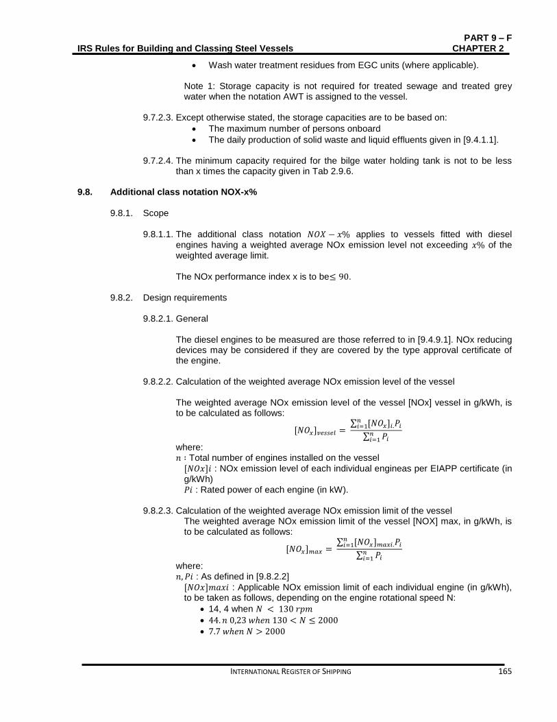
PART 9 – F IRS Rules for Building and Classing Steel Vessels CHAPTER 2
INTERNATIONAL REGISTER OF SHIPPING 165
Wash water treatment residues from EGC units (where applicable).
Note 1: Storage capacity is not required for treated sewage and treated grey water when the notation AWT is assigned to the vessel.
9.7.2.3. Except otherwise stated, the storage capacities are to be based on:
The maximum number of persons onboard
The daily production of solid waste and liquid effluents given in [9.4.1.1].
9.7.2.4. The minimum capacity required for the bilge water holding tank is not to be less than x times the capacity given in Tab 2.9.6.
9.8. Additional class notation NOX-x%
9.8.1. Scope
9.8.1.1. The additional class notation 𝑁𝑂𝑋 − 𝑥% applies to vessels fitted with diesel engines having a weighted average NOx emission level not exceeding 𝑥% of the weighted average limit. The NOx performance index x is to be≤ 90.
9.8.2. Design requirements
9.8.2.1. General
The diesel engines to be measured are those referred to in [9.4.9.1]. NOx reducing devices may be considered if they are covered by the type approval certificate of the engine.
9.8.2.2. Calculation of the weighted average NOx emission level of the vessel The weighted average NOx emission level of the vessel [NOx] vessel in g/kWh, is to be calculated as follows:
[𝑁𝑂𝑥]𝑣𝑒𝑠𝑠𝑒𝑙 = ∑ [𝑁𝑂𝑥]𝑖.𝑃𝑖
𝑛𝑖=1
∑ 𝑃𝑖𝑛𝑖=1
where: 𝑛 ∶ Total number of engines installed on the vessel
[𝑁𝑂𝑥]𝑖 : NOx emission level of each individual engineas per EIAPP certificate (in g/kWh) 𝑃𝑖 : Rated power of each engine (in kW).
9.8.2.3. Calculation of the weighted average NOx emission limit of the vessel The weighted average NOx emission limit of the vessel [NOX] max, in g/kWh, is to be calculated as follows:
[𝑁𝑂𝑥]𝑚𝑎𝑥 = ∑ [𝑁𝑂𝑥]𝑚𝑎𝑥𝑖.𝑃𝑖
𝑛𝑖=1
∑ 𝑃𝑖𝑛𝑖=1
where: 𝑛, 𝑃𝑖 : As defined in [9.8.2.2]
[𝑁𝑂𝑥]𝑚𝑎𝑥𝑖 : Applicable NOx emission limit of each individual engine (in g/kWh), to be taken as follows, depending on the engine rotational speed N:
14, 4 when 𝑁 < 130 𝑟𝑝𝑚
44. 𝑛 0,23 𝑤ℎ𝑒𝑛 130 < 𝑁 ≤ 2000 7.7 𝑤ℎ𝑒𝑛 𝑁 > 2000
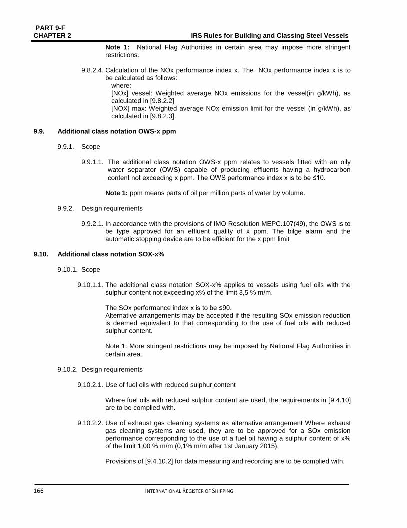
PART 9-F CHAPTER 2 IRS Rules for Building and Classing Steel Vessels
166 INTERNATIONAL REGISTER OF SHIPPING
Note 1: National Flag Authorities in certain area may impose more stringent restrictions.
9.8.2.4. Calculation of the NOx performance index x. The NOx performance index x is to be calculated as follows:
where: [NOx] vessel: Weighted average NOx emissions for the vessel(in g/kWh), as calculated in [9.8.2.2] [NOX] max: Weighted average NOx emission limit for the vessel (in g/kWh), as calculated in [9.8.2.3].
9.9. Additional class notation OWS-x ppm
9.9.1. Scope
9.9.1.1. The additional class notation OWS-x ppm relates to vessels fitted with an oily water separator (OWS) capable of producing effluents having a hydrocarbon content not exceeding x ppm. The OWS performance index x is to be ≤10.
Note 1: ppm means parts of oil per million parts of water by volume.
9.9.2. Design requirements
9.9.2.1. In accordance with the provisions of IMO Resolution MEPC.107(49), the OWS is to be type approved for an effluent quality of x ppm. The bilge alarm and the automatic stopping device are to be efficient for the x ppm limit
9.10. Additional class notation SOX-x%
9.10.1. Scope
9.10.1.1. The additional class notation SOX-x% applies to vessels using fuel oils with the sulphur content not exceeding x% of the limit 3,5 % m/m.
The SOx performance index x is to be ≤90. Alternative arrangements may be accepted if the resulting SOx emission reduction is deemed equivalent to that corresponding to the use of fuel oils with reduced sulphur content. Note 1: More stringent restrictions may be imposed by National Flag Authorities in certain area.
9.10.2. Design requirements
9.10.2.1. Use of fuel oils with reduced sulphur content Where fuel oils with reduced sulphur content are used, the requirements in [9.4.10] are to be complied with.
9.10.2.2. Use of exhaust gas cleaning systems as alternative arrangement Where exhaust gas cleaning systems are used, they are to be approved for a SOx emission performance corresponding to the use of a fuel oil having a sulphur content of x% of the limit 1,00 % m/m (0,1% m/m after 1st January 2015). Provisions of [9.4.10.2] for data measuring and recording are to be complied with.

PART 9 – F IRS Rules for Building and Classing Steel Vessels CHAPTER 2
INTERNATIONAL REGISTER OF SHIPPING 167
9.11. Onboard Surveys
9.11.1. Application
9.11.1.1. Survey requirements for the additional class notations Clean vessel, and other additional class notations listed here are given in Part 9A, Chapter 3, Sec 8. This section contains additional requirements applying to the additional class notations Clean vessel.
9.11.2. Periodical tests and measurements done by the vessel Owner
9.11.2.1. Purpose
The following tests and measurements, done under the accountability of the vessel Owner, are intended to control the effective implementation of the waste management procedures and the constant level over time kept by the quality of the effluents discharged at water.
9.11.2.2. Initial period - Initial tests The Vessel owner is to proceed with the following measurements and analyses during the first year of commercial operation:
Collection of actual on board data’s concerning the volume of wastes generation, using the waste streams as defined in Table 2.9.6
Analyses of the effluent and waste streams for pollutant concentration, according to the periodicity defined in Table 2.9.11
Table 2.10.11: Frequency of analyses of waste streams during the first year of service
Waste stream
Frequency of analyses
Metals analyses in incinerator ash(1)
quarterly
Metals analyses in grey water quarterly
Effluent analyses sewage treatment plan
yearly
Effluent analyses for Advanced Wastewater Treatment
quarterly
(1) If the vessel is equipped to dump incinerator as hover-board.
9.11.2.3. Periodical tests after first year of service
A qualified laboratory periodically sample and analyze the effluents and wastes usually discharged to water are to be. The frequency of these tests in a five-year term period is specified in Table 2.9.12.Table 2.9.13 lists the number of occurrences where the pollutant maximum concentration may exceed the limit concentration specified in Table 2.9.14 and Table 2.9.10, without exceeding the reject value. During the periodical surveys Test results of the measurements are to be recorded in the waste water and garbage logbooks and made available to the surveyor.
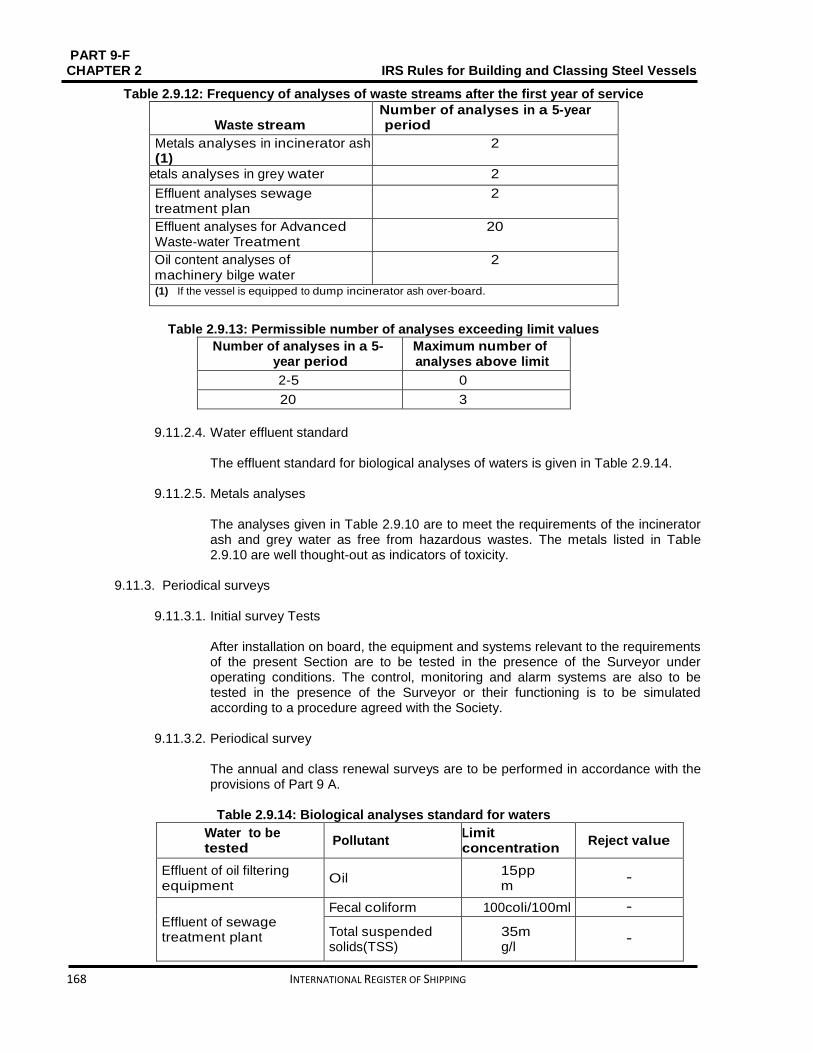
PART 9-F CHAPTER 2 IRS Rules for Building and Classing Steel Vessels
168 INTERNATIONAL REGISTER OF SHIPPING
Table 2.9.12: Frequency of analyses of waste streams after the first year of service
Waste stream
Number of analyses in a 5-year period
Metals analyses in incinerator ash (1)
2
Metals analyses in grey water 2
Effluent analyses sewage treatment plan
2
Effluent analyses for Advanced Waste-water Treatment
20
Oil content analyses of machinery bilge water
2
(1) If the vessel is equipped to dump incinerator ash over-board.
Table 2.9.13: Permissible number of analyses exceeding limit values
Number of analyses in a 5-year period
Maximum number of analyses above limit
2-5 0
20 3
9.11.2.4. Water effluent standard
The effluent standard for biological analyses of waters is given in Table 2.9.14.
9.11.2.5. Metals analyses The analyses given in Table 2.9.10 are to meet the requirements of the incinerator ash and grey water as free from hazardous wastes. The metals listed in Table 2.9.10 are well thought-out as indicators of toxicity.
9.11.3. Periodical surveys
9.11.3.1. Initial survey Tests
After installation on board, the equipment and systems relevant to the requirements of the present Section are to be tested in the presence of the Surveyor under operating conditions. The control, monitoring and alarm systems are also to be tested in the presence of the Surveyor or their functioning is to be simulated according to a procedure agreed with the Society.
9.11.3.2. Periodical survey
The annual and class renewal surveys are to be performed in accordance with the provisions of Part 9 A.
Table 2.9.14: Biological analyses standard for waters
Water to be tested
Pollutant Limit concentration
Reject value
Effluent of oil filtering equipment
Oil 15ppm
−
Effluent of sewage treatment plant
Fecal coliform 100coli/100ml −
Total suspended solids(TSS)
35mg/l
−

PART 9 – F IRS Rules for Building and Classing Steel Vessels CHAPTER 2
INTERNATIONAL REGISTER OF SHIPPING 169
5-day Biochemical Oxygen Demand (BOD5)
25mg/l
−
Effluent of AWT unit(applies only to vessels having the additional class notation AWT)
Fecal coliform 14coli/100ml 43coli/100ml
TSS 10mg/l
25mg/l
BOD5 20mg/l
30mg/l
Total Nitrogen(TN) 10mg/l
25mg/l
Total phosphorus(TP)
1mg/l
5mg/l
PART 9-F CHAPTER 3 IRS Rules for Building and Classing Steel Vessels
170 INTERNATIONAL REGISTER OF SHIPPING
CHAPTER 3 TRANSPORT OF DANGEROUS GOODS
CONTENTS SECTION 1 GENERAL ................................................................................................................... 171
SECTION 2 TYPE G ....................................................................................................................... 186
SECTION 3 TYPE C ....................................................................................................................... 212
SECTION 4 TYPE N ....................................................................................................................... 238
SECTION 5 OIL SEPARATOR VESSEL ..................................................................................... 264
SECTION 6 SUPPLY VESSEL ..................................................................................................... 282
SECTION 7 DG ................................................................................................................................ 300
SECTION 8 DGL.............................................................................................................................. 310
SECTION 9 DGD ............................................................................................................................. 316

PART 9 – F IRS Rules for Building and Classing Steel Vessels CHAPTER 3
INTERNATIONAL REGISTER OF SHIPPING 171
SECTION 1 GENERAL Contents
1.1. General ........................................................................................................................................... 172
1.2. Definitions ....................................................................................................................................... 172
1.3. Classification................................................................................................................................... 176
1.4. Dangerous goods’ list - carriage special provisions ....................................................................... 177
1.5. Carriage of dry cargoes .................................................................................................................. 177
1.6. Carriage of liquid cargoes ............................................................................................................... 179
1.7. Certification, inspection and testing of cargo system ..................................................................... 182

PART 9-F CHAPTER 3 IRS Rules for Building and Classing Steel Vessels
172 INTERNATIONAL REGISTER OF SHIPPING
1.1. General
1.1.1. Symbols
L: Rule length, in m, defined in Part 9 C, Chapter 1, Sec 1, [1.2]. B: Breadth, in m, defined in Part 9 C, Chapter 1, Sec 1, [1.2].
D: Depth, in m, defined in Part 9 C, Chapter 1, Sec 1, [1.2].
T: Draught, in m, defined in Part 9 C, Chapter 1, Sec 1, [1.2].
1.1.2. Application
1.1.2.1. The necessities of this Chapter apply to vessels intended for the carriage of dangerous goods.
1.1.2.2. Vessels dealt with in this Chapter are to fulfill the requirements stated under Part
A, Part B and Part C, as applicable. Additional measures and Regulations changing from country to country or from continent to continent are to be complied with.
1.2. Definitions
1.2.1. Accommodation
1.2.1.1. The Accommodation means spaces intended for the use of persons normally living on board, including galleys, food stores, lavatories, washrooms, bathrooms, laundries, halls, alleyways, etc., but excluding the wheelhouse.
1.2.2. ADN
ADN means European agreement concerning the international carriage of dangerous goods by inland water-ways.
1.2.3. Bilge Water
Bilge water means oily water from the engine room bilges, the peaks, the cofferdams and the double hull spaces.
1.2.4. Bulkhead
1.2.4.1. Bulkhead means a metal wall, generally vertical, inside the vessel and which is circumscribed by the bottom, the side plating, a deck, the hatchway covers or by another bulkhead.
1.2.5. Cargo area of tank vessels
1.2.5.1. Cargo area of tank vessels means the whole of the spaces defined in [1.2.5.2] to
[1.2.5.4] (see Fig 3.1.1). 1.2.5.2. Cargo area of tank vessels (additional part above deck)
Cargo area of tank vessels (additional part above deck) (When anti-explosion protection is required, comparable to zone 1, see [1.2.9]) means the spaces not included in the main part of cargo area above deck consist of 1.00 m radius spherical segments centred over the ventilation openings of the cofferdams and the
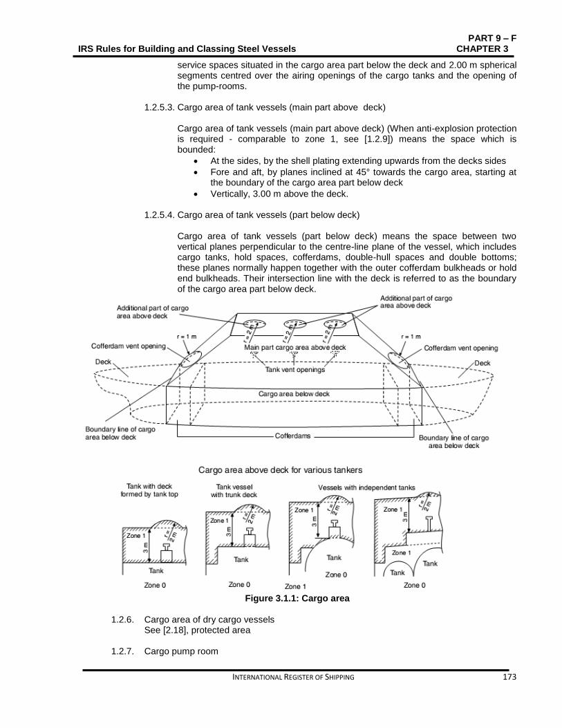
PART 9 – F IRS Rules for Building and Classing Steel Vessels CHAPTER 3
INTERNATIONAL REGISTER OF SHIPPING 173
service spaces situated in the cargo area part below the deck and 2.00 m spherical segments centred over the airing openings of the cargo tanks and the opening of the pump-rooms.
1.2.5.3. Cargo area of tank vessels (main part above deck)
Cargo area of tank vessels (main part above deck) (When anti-explosion protection is required - comparable to zone 1, see [1.2.9]) means the space which is bounded:
At the sides, by the shell plating extending upwards from the decks sides
Fore and aft, by planes inclined at 45° towards the cargo area, starting at the boundary of the cargo area part below deck
Vertically, 3.00 m above the deck.
1.2.5.4. Cargo area of tank vessels (part below deck)
Cargo area of tank vessels (part below deck) means the space between two vertical planes perpendicular to the centre-line plane of the vessel, which includes cargo tanks, hold spaces, cofferdams, double-hull spaces and double bottoms; these planes normally happen together with the outer cofferdam bulkheads or hold end bulkheads. Their intersection line with the deck is referred to as the boundary of the cargo area part below deck.
Figure 3.1.1: Cargo area
1.2.6. Cargo area of dry cargo vessels
See [2.18], protected area
1.2.7. Cargo pump room

PART 9-F CHAPTER 3 IRS Rules for Building and Classing Steel Vessels
174 INTERNATIONAL REGISTER OF SHIPPING
1.2.7.1. Cargo pump-room (When anti-explosion protection is required, comparable to zone
1, see [1.2.9]) means a service space where the cargo pumps and stripping pumps are fitted together with their operational equipment.
1.2.8. Cargo tank
1.2.8.1. Cargo tank (When anti-explosion protection is required, comparable to zone 0, see
[1.2.9]) means a tank which is always attached to the vessel and the boundaries of which are either formed by the hull itself or by walls distinct from the hull and which is intended for the carriage of dangerous goods.
1.2.9. Classification of zones
1.2.9.1. Zone 0
Areas in which dangerous explosive atmospheres of gases, vapours or sprays exist permanently or during long periods.
1.2.9.2. Zone 1 Areas in which dangerous explosive atmospheres of gases, vapours or sprays are likely to occur occasionally.
1.2.9.3. Zone 2 Areas in which dangerous explosive atmospheres of gases, vapours or sprays are likely to occur rarely and if so for short periods only.
1.2.10. Cofferdam
Cofferdam (when anti-explosion protection is required, comparable to zone 1, see [1.2.9.1]) means an athwartship compartment which is bounded by watertight bulkheads and which can be inspected. The cofferdam shall spread over the whole area of the end bulkheads of the tanks. The bulkheads not facing the cargo area shall prolong from one side of the vessel to the other and from the bottom to the deck in one frame plane.
1.2.11. Design pressure
1.2.11.1. Design pressure means the pressure on the basis of which the cargo tank or the residual cargo tank has been planned and built.
1.2.12. Dangerous goods
1.2.12.1. Dangerous goods mean substances and articles the carriage of which is prohibited
by ADN, or authorized only under the conditions prescribed therein.
1.2.13. Flash-point
1.2.13.1. Flash-point means the lowest temperature of a liquid at which its vapours form a flammable mixture with air.
1.2.14. Independent cargo tank
1.2.14.1. Independent cargo tank (when anti-explosion protection is required, comparable to
zone 0) means a cargo tank which is lastingly built in, but which is independent of the vessel's structure.
1.2.15. Limited explosion risk electrical apparatus

PART 9 – F IRS Rules for Building and Classing Steel Vessels CHAPTER 3
INTERNATIONAL REGISTER OF SHIPPING 175
1.2.15.1. Limited explosion risk electrical apparatus means an electrical apparatus which, during normal operation, does not cause sparks or exhibits surface temperatures which are above the required temperature class, including e.g.:
Three-phase squirrel cage rotor motors
Brushless generators with contactless excitation
Fuses with an enclosed fuse element
Contactless electronic apparatus or means an electrical apparatus with an enclosure protected against water jets (degree of protection IP55) which during normal operation does not exhibit surface temperatures which are above the required temperature class.
1.2.16. Machinery spaces
1.2.16.1. Machinery spaces are all spaces covering propulsion machinery, boilers, fuel oil
units, steam and internal combustion engines, generators and major electrical machinery, oil filling stations, refrigerating, establishing, ventilation and air conditioning machinery, and similar spaces, and trunks to such spaces.
1.2.17. Pressure tank
1.2.17.1. Pressure tank means a tank designed and approved for a working pressure
≥400 kPa (4 bar).
1.2.18. Protected area
1.2.18.1. Protected area means:
a) the cargo hold or holds (when anti-explosion protection is required, comparable to zone 1, see [1.2.9]) of the vessel
b) the space situated above the deck (when anti-explosion protection is required, comparable to zone 2, see [1.2.9]), bounded:
athwarships, by vertical planes corresponding to the side plating
fore and aft, by vertical planes corresponding to the end bulkheads of the hold; and
upwards, by a horizontal plane 2 m above the upper level of the load, but at least by a horizontal plane 3 m above the deck.
1.2.19. Residual cargo
1.2.19.1. Residual cargo means liquid cargo remaining in the cargo tank or cargo piping after
unloading without the use of the stripping system.
1.2.20. Slops
1.2.20.1. Slops means a combination of cargo residues and washing water, rust or sludge which is either suitable or not for pumping.
1.2.21. Service space
1.2.21.1. Service space means a space which is accessible during the operation of the
vessel and which is neither part of the accommodation nor of the cargo tanks, with the exclusion of the fore peak and aft peak, provided no machinery has been installed in these latter spaces.

PART 9-F CHAPTER 3 IRS Rules for Building and Classing Steel Vessels
176 INTERNATIONAL REGISTER OF SHIPPING
1.2.22. Temperature class
1.2.22.1. Temperature class means a grouping of flammable gases and vapours of flammable liquids according to their ignition temperature; and of the electrical apparatus planned to be used in the corresponding potentially explosive atmosphere according to their maximum surface temperature.
1.2.23. Test pressure
1.2.23.1. Test pressure means the pressure at which a cargo tank, a residual cargo tank, a
cofferdam or the loading and unloading pipes shall be tested prior to being brought into service for the first time and subsequently regularly within approved times.
1.2.24. UN Model Regulations
1.2.24.1. UN Model Regulations means the Model Regulations annexed to the sixteenth
revised edition of the Recommendations on the Transport of Dangerous Goods published by the United Nations (ST/SG/AC.10/1/Rev.16).
1.2.25. UN number
1.2.25.1. UN number means the four-figure identification number of the substance or article
taken from the United Nations Model Regulations.
1.3. Classification
1.3.1. Classification of dangerous goods
1.3.1.1. Each class outlines one type of dangerous goods. In some classes divisions are distincted. The numerical order of the classes and divisions is not that of the degree of danger. The classes defined in UN Model Regulations are given in Tab 1.
1.3.1.2. Despite from foregoing, the current edition of the ADN Regulations is always to be
applied to the classification of substances and other requirements (e.g. the filling ratio).
Table 3.1.1: Classification of dangerous goods
Class Description
Class 1 1.1 1.2
1.3 1.4 1.5 1.6
Explosives Substances and articles which have a mass explosion hazard Substances and articles which have a projection hazard but not a mass explosion hazard Substances and articles which have a fire hazard and either a minor blast hazard or a minor projection hazard or both, but not a mass explosion hazard Substances and articles which present no significant hazard Very intensive substances which have a mass explosion hazard Extremely intensive articles which do not have a mass explosion hazard
Class 2 2.1 2.2 2.3
Gases Flammable gases Non-flammable, non-toxic gases Toxic gases
Class 3 Flammable liquids
Class 4
Flammable solids; substances liable to spontaneous combustion; substances which, in contact with water, emit flammable gases
PART 9 – F IRS Rules for Building and Classing Steel Vessels CHAPTER 3
INTERNATIONAL REGISTER OF SHIPPING 177
4.1 4.2 4.3
Flammable solids, self-reactive substances and solid desensitized explosives Substances liable to spontaneous combustion Substances which in contact with water emit flammable gases
Class 5 5.1 5.2
Oxidizing substances and organic peroxides Oxidizing substances Organic peroxides
Class 6 6.1 6.2
Toxic and infectious substances Toxic substances Infectious substances
Class 7 Radioactive material
Class 8 Corrosive substances
Class 9 Miscellaneous dangerous substances and articles
1.4. Dangerous goods’ list - carriage special provisions
1.4.1. General
1.4.1.1. As well as the provisions referred to or given in the tables referred to in [4.2] and [4.3], the general requirements of each Section of this Chapter are to be observed. These general requirements are not given in the tables. The special provision prevails, when a general requirement is contradictory to a special provision.
1.4.2. Table A: List of dangerous goods in numerical order
1.4.2.1. Table A lists dangerous substances or articles in numerical order (UN number)
with their classification and the special provisions for the transport. 1.4.2.2. Explanatory notes for each column are given in ADN Section 3.2.1.
1.4.3. Table C: List of dangerous goods accepted for carriage in tank vessels in numerical order 1.4.3.1. Substances approved for carriage in tankers
The dangerous goods of the classes listed below may be carried in tankers depending on their structure: Class 2 - Gases compressed, liquefied or dissolved under pressure Class 3 - Flammable liquids Class 5.1 - Oxidizing substances Class 6.1 - Toxic substances Class 8 - Corrosive substances Class 9 - Miscellaneous dangerous substances and articles.
1.4.3.2. Table C lists dangerous substances accepted for carriage in tank vessels in numerical order (UN number), with their classification and the special provisions for the transport.
1.4.3.3. Explanatory notes for each column are given in ADN Section 3.2.3.
1.5. Carriage of dry cargoes
1.5.1. Mode of carriage of goods
1.5.1.1. Carriage of packages
The masses given for packages shall be the gross masses unless otherwise specified. The mass of the container or vehicle shall not be included in the gross mass of such packages, when packages are carried in containers or vehicles.

PART 9-F CHAPTER 3 IRS Rules for Building and Classing Steel Vessels
178 INTERNATIONAL REGISTER OF SHIPPING
1.5.1.2. Carriage in containers, in intermediate bulk containers (IBCs) and in large
packaging, in MEGCs, in portable tanks and in tank-containers The carriage of containers, IBCs, large packaging, MEGCs, portable tanks and tank containers shall be in accordance with the ADN provisions related to the carriage of packages.
1.5.1.3. Vehicles and wagons
The carriage of vehicles and wagons shall be in accordance with the ADN provisions applicable to the carriage of packages.
1.5.1.4. Carriage in bulk
The carriage of dangerous goods in bulk is only allowed if the code “B” appears in column (8) of Table A, Chapter 3.2., Part 6 of ADN.
1.5.2. Vessels
1.5.2.1. Permitted vessels The Vessels which are carrying dangerous goods in quantities not exceeding those indicated in 7.1.4.1.1, or, if applicable, in 7.1.4.1.2 of ADN Regulations are permitted to carry dangerous goods in restricted quantities. The maximum allowed quantities are specified in ADN Regulations, Part 7, and 7.1.4.1 or in other Regulations implemented by the national Authority. Vessels for the transport of dangerous goods in restricted quantities have to satisfy Chapter 3, Sec 7.
1.5.2.2. Structural configuration Vessels for the transport of dangerous goods of classes 2, 3, 4.1, 5.2, 6.1, 7, 8 or 9, with the exception of those for which a No. 1 model label is required in column (5) of table A of Chapter 3.2, Part 3 of ADN Regulations to be carried in quantities greater than those indicated in 7.1.4.1.1, or, if applicable, in 7.1.4.1.2 of ADN Regulations have to be built as double-hull dry cargo vessels. These vessels have also to meet with the applicable additional Rules of Chapter 3, Sec 7, [7.6].
1.5.3. Pushed convoys and side-by-side formations
1.5.3.1. The requirements [1.5.3.2] to [1.5.3.4] shall be applied where a convoy or side-by-
side formation comprises at least one vessel carrying dry dangerous goods, 1.5.3.2. The entire pushed convoy or the side-by-side formation shall be deemed to be a
single vessel for the purposes of the application of the requirements of this Chapter, with the exception of those equivalents to 7.1.4.1.1 and 7.1.4.1.2 of ADN Regulations.
1.5.3.3. The Vessels carrying dangerous goods shall comply with the requirements of
Chapter 3, Sec 7. (See also [1.5.2.1] and [1.5.2.2]).
1.5.3.4. The propulsion vessel and vessels not carrying dangerous goods shall comply with the requirements of Chapter 3, Sec 9.
1.5.4. Materials of construction
1.5.4.1. The vessel's hull and the cargo holds must be constructed of hull structural steel
conforming to the applicable requirements of Part 2.

PART 9 – F IRS Rules for Building and Classing Steel Vessels CHAPTER 3
INTERNATIONAL REGISTER OF SHIPPING 179
1.6. Carriage of liquid cargoes
1.6.1. Carriage in cargo tanks
1.6.1.1. General Substances, their assignment to the various types of tank vessels and the special conditions for their carriage in these tank vessels, are listed in ADN Regulations Table C.
1.6.1.2. Substances, which have to be carried in a tank vessel of type N, open, may also be
carried in a tank vessel of type N, open, with flame arresters; type N, closed; types C or G provided that all conditions of carriage prescribed for tank vessels of type N, open, as well as all other conditions of carriage prescribed in the list of substances of ADN Regulations Table C are met.
1.6.1.3. Substances which have to be carried in a tank vessel of type N, open, with flame
arresters, may also be carried in tank vessels of type N, closed, and types C or G provided that all conditions of carriage prescribed for tank vessels of type N, open, with flame arresters, as well as all other conditions of carriage prescribed in the list of substances of ADN Regulations Table C are met.
1.6.1.4. Substances which have to be carried in a tank vessel of type N, closed, may also
be carried in tank vessels of type C or G provided that all conditions of carriage prescribed for tank vessels of type N, closed, in addition to all other conditions of carriage prescribed in the list of ADN Regulations Table C are met.
1.6.1.5. Substances which have to be carried in a tank vessel of type C may also be carried
in tank vessels of type G provided that all conditions of carriage prescribed for tank vessels of type C as well as all other conditions of carriage prescribed in ADN Regulations Table C are met.
1.6.1.6. Oily and greasy wastes resulting from the operation of the vessel may only be
carried in fire resistant receptacles, fitted with a lid, or in cargo tanks.
1.6.2. Permitted vessels
1.6.2.1. Dangerous goods may be carried in tank vessels of Types N, C or G in accordance with the applicable requirements of Chapter 3, Sec 2 to Sec 6. The type of tank vessel to be used is specified in ADN Regulations Table C.
1.6.2.2. The Society issue the substances accepted for carriage in the vessel will be
indicated. 1.6.2.3. The relief pressure of the safety valves or of the high-velocity vent valves, the
design pressure and the test pressure of cargo tanks will be specified.
1.6.3. Pushed convoys and side-by-side formations
1.6.3.1. The requirements [1.6.3.2] to [1.6.3.4] shall be applied where a convoy or side-by-side formation includes at least one vessel carrying liquid dangerous goods.
1.6.3.2. The Vessels carrying dangerous goods shall fulfill the requirements of [1.6.2]. 1.6.3.3. The propulsion vessel shall fulfill the requirements of Chapter 3, Sec 8.

PART 9-F CHAPTER 3 IRS Rules for Building and Classing Steel Vessels
180 INTERNATIONAL REGISTER OF SHIPPING
1.6.3.4. The vessels not carrying dangerous goods shall comply with the requirements of Chapter 3, Sec 9.
Table 3.1.2: Tank vessel varieties
Type of tank vessel
Description
General configuration
Txy
Remarks
Type G Carriage of gases
G11
G21
Type C
Carriage of liquids • flush deck • double hull
C11 Double hull
C21 Double hull
C22 Double hull
Type N Carriage of liquids
N11
N21
N31
N41
N22 Single hull
N23 Double hull
N32 Single hull
N33 Double hull
N42 Single hull
N43 Double hull
1.6.4. Types of tank vessels
1.6.4.1. Tank vessel varieties
The tank vessel type, cargo tank design and cargo tank type are to be determined in compliance with Table C of ADN Regulations Chapter 3.2. The basic tank types and their structural configuration are defined in Table 3.1.2, where:
T: Type of tank vessel
T = G, for type G tank vessel
T = C, for type C tank vessel
T = N, for type N tank vessel x: Cargo tank design
x = 1, for pressure tank
x = 2, for closed cargo tank
x= 3, for open cargo tank with flame arrester
x = 4, for open cargo tank y: Cargo tank type
y = 1, for independent cargo tank
y = 2, for integral cargo tank
y = 3, for cargo tank with walls distinct from the outer hull
1.6.4.2. Minimum requirements for double hull arrangements The following minimum requirements are to be met where prescribed distances from ADN Regulations or other Statutory Regulations do not have to be sustained

PART 9 – F IRS Rules for Building and Classing Steel Vessels CHAPTER 3
INTERNATIONAL REGISTER OF SHIPPING 181
between the tank wall and the vessel's side or bottom plating for the carriage of particular substances,:
The distance between the tanks and the side plating of the vessel on each side shall not be less than 8% of the breadth B. This distance must afford easy access to the tanks
The distance between the tanks and the bottom of the vessel must allow inspection and must be at least 60 cm. However, the distance between a tank pump well and the vessel's bottom may be reduced to 50 cm pro-vided that the volume of the pump well is not greater than 0.1 m³
Independent tanks, if they are easy to move out of the vessel.
1.6.4.3. Stability Cargo tanks are normally to be provided with centre longitudinal bulkheads where the tank breadth exceeds 0.7 B. Additional proof of stability is to be provided in compliance with Chapter 2, Sec 6, [6.5] where the tank breadth is greater than the figure mentioned and centre longitudinal bulkheads are not fitted.
1.6.5. Pressure cargo tanks
1.6.5.1. Scantling and arrangements of pressure cargo tanks are to be in compliance with Part D, Chapter 3.
1.6.6. Blanketing of the cargo and inerting.
1.6.6.1. In cargo tanks and the corresponding piping, inerting in the gaseous phase or blanketing of the cargo may be necessary. Inerting and blanketing of the cargo are defined in [1.6.6.2] and [1.6.6.3].
1.6.6.2. Inerting
Cargo tanks and the corresponding piping and other spaces for which inerting is prescribed in column (20) of Table C of ADN Regulations chapter 3.2 are filled with gases or vapours which pre-vent combustion, do not return with the cargo and maintain this state.
1.6.6.3. Blanketing Spaces in the cargo tanks above the cargo and the corresponding piping are filled with a liquid, gas or vapour so that the cargo is detached from the air and this state is preserved.
1.6.7. Materials of construction
1.6.7.1. The vessel's hull and the cargo tanks must be built of hull structural steel conforming to the applicable requirements Part 2 or other at least the same metal.
1.6.7.2. Independent cargo tanks may also be constructed of other materials provided
these have at least same mechanical properties and resistance alongside the effects of temperature and fire.
1.6.7.3. Every part of the vessel as well as any installation and equipment which may come
into contact with the cargo shall consist of materials which can neither be dangerously affected by the cargo nor cause decay of the cargo or react with it so as to form harmful or hazardous products.

PART 9-F CHAPTER 3 IRS Rules for Building and Classing Steel Vessels
182 INTERNATIONAL REGISTER OF SHIPPING
1.6.7.4. Vapour pipes and gas discharge pipes shall be protected against corrosion.
1.6.7.5. The use of wood, aluminium alloys or synthetic materials within the cargo area is
only allowed for:
Gangways and external ladders
Movable items of equipment (aluminium gauging rods are, however permitted, provided that they are fitted with brass feet or protected in another way to avoid sparking)
Chocking of cargo tanks which are independent of the vessel's hull and chocking of installations and equipment
Masts and similar round timber
Engine parts
Parts of the electrical installation
Loading and unloading appliances
Lids of boxes which are placed on the deck.
1.6.7.6. The usage of wood or synthetic materials within the cargo area is only allowed for supports and stops of any kind.
1.6.7.7. The usage of synthetic materials or rubber within the cargo area is only permitted
for:
Coating of cargo tanks and of pipes for loading and unloading
All kinds of gaskets (e.g. for dome or hatch covers)
Electric cables
Hoses for loading and unloading
Insulation of cargo tanks and of hoses for loading and unloading.
1.6.7.8. All permanently fitted materials in the place or wheelhouse, with the exception of furniture, shall not readily burn. They shall not evolve fumes or toxic gases in dangerous quantities, in a fire.
1.6.7.9. The paint used in the cargo area shall not be responsible to produce sparks in case
of impact.
1.6.7.10. The use of synthetic material for vessel's boats is allowed only if the material does not readily ignite.
1.7. Certification, inspection and testing of cargo system
1.7.1. Application
1.7.1.1. The requirements of this section are related to cargo piping and other equipment fitted in the cargo area. They supplement those given in Part D, Chapter 3, Sec 20 for piping systems.
1.7.2. Workshop tests
1.7.2.1. Tests for materials
Materials used for pipes, valves and fittings are to be subjected to the tests specified in Part D, Chapter 9, Sec 20, [20.3].
1.7.2.2. Inspection of welded joints

PART 9 – F IRS Rules for Building and Classing Steel Vessels CHAPTER 3
INTERNATIONAL REGISTER OF SHIPPING 183
Welded joints are to be subjected to the examinations specified in Part D, Chapter 9, Sec 20, [20.3.3] for class II pipes.
1.7.2.3. Hydrostatic testing
a) In accordance with the relevant provisions of Part D, Chapter 9, Sec 20,
[20.4]cargo pipes, valves, fittings and pump casings are to be submitted to hydrostatic tests.
b) In accordance with the relevant provisions of Part D, Chapter 9, Sec 20, [20.4] Expansion joints and cargo hoses are to be submitted to hydrostatic tests.
c) Where fitted, bellow pieces of gas-tight penetration glands are to be pressure tested.
1.7.2.4. Tightness tests
Tightness of the following devices is to be examined:
gas-tight penetration glands
cargo tank P/V and high velocity valves. Note 1: These tests may be performed in the workshops or on board.
1.7.2.5. Check of the safety valves setting
According to applicable Society’s Rules the setting pressure of the pressure/vacuum valves is to be checked.
1.7.2.6. Summarizing table
Inspections and tests needed for cargo piping and other equipment fitted in the cargo area are summarized in Table 3.1.3
1.7.3. On board tests
1.7.3.1. Pressure test
The cargo piping system is to be checked for leakage under operational conditions, after installation on board.

PART 9-F CHAPTER 3 IRS Rules for Building and Classing Steel Vessels
184 INTERNATIONAL REGISTER OF SHIPPING
Table 3.1.3: Inspection and testing at works
N°
Item
Tests for materials Inspections and tests for the products
References
to the Rules Y/N (1)
Type of material certificate (2)
During manufacturing (1)
After completion (1) (3)
Type of product
certificate (2)
1 pipes, valves and
fittings (liquid cargo)
Y • C where ND>100mm • W where ND≤100mm
Y (4)
Y
C
[17.2.1] [1.7.2.1] [1.7.2.2] [1.7.2.3]
(7)
2 pipes, valves and
fittings (liquefied
gas)
Y • C where ND>100mm • W where ND≤100mm
Y (4)
Y
C
[1.7.2.1] [1.7.2.1] [1.7.2.2] [1.7.2.3]
3 expansion joints
and cargo hoses
Y (5)
W
N
Y
C
[1.7.2.1]
[1.7.2.3]
4 cargo pumps
(liquid cargo)
Y • C for cast body • W for welded construction
Y (6)
Y
W
see note (6)
[1.7.2.3]
5 cargo pumps (liquefied gas)
Y • C for cast body • W for welded construction
Y (6)
Y
C
see note (6)
[1.7.2.3]
(7) 6 compres
sors Y • C for cast body
• W for welded construction
Y (6)
Y
C
see note (6)
[1.7.2.3]
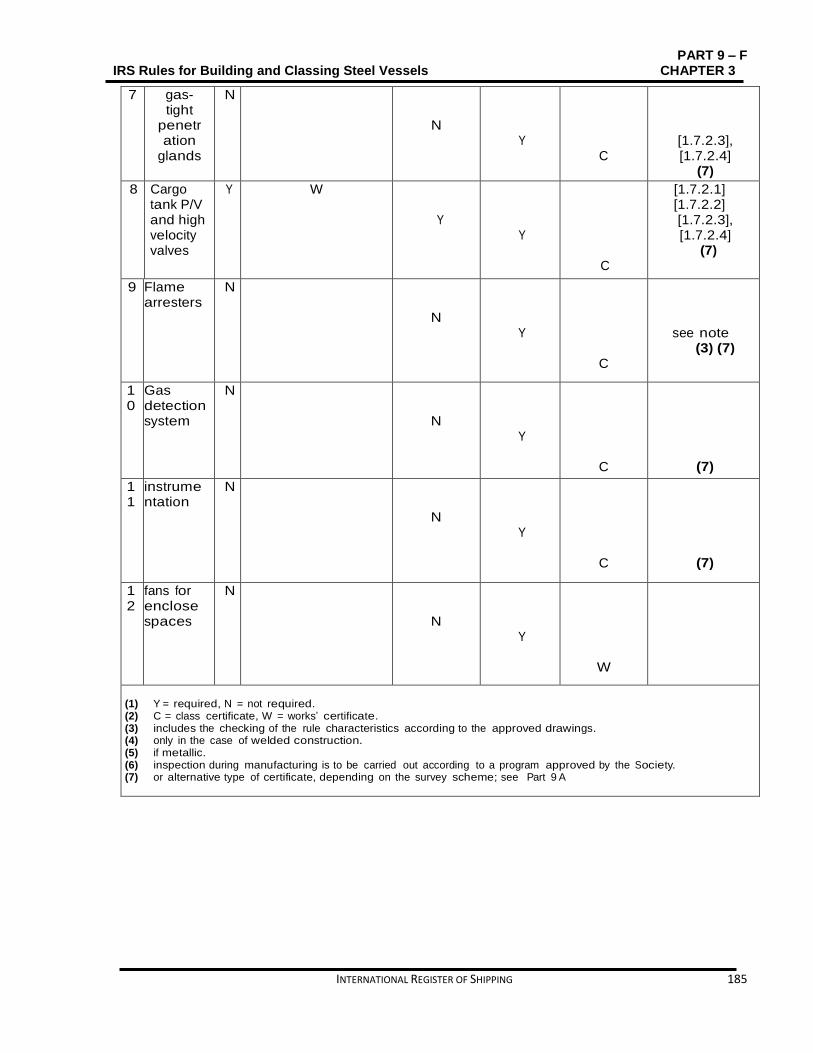
PART 9 – F IRS Rules for Building and Classing Steel Vessels CHAPTER 3
INTERNATIONAL REGISTER OF SHIPPING 185
7 gas-tight
penetration
glands
N
N
Y
C
[1.7.2.3], [1.7.2.4]
(7)
8 Cargo tank P/V and high velocity valves
Y W
Y
Y
C
[1.7.2.1] [1.7.2.2] [1.7.2.3], [1.7.2.4]
(7)
9 Flame arresters
N
N
Y
C
see note (3) (7)
10
Gas detection system
N
N
Y
C
(7)
11
instrumentation
N
N
Y
C
(7)
12
fans for enclose spaces
N
N
Y
W
(1) Y = required, N = not required. (2) C = class certificate, W = works’ certificate. (3) includes the checking of the rule characteristics according to the approved drawings. (4) only in the case of welded construction. (5) if metallic. (6) inspection during manufacturing is to be carried out according to a program approved by the Society. (7) or alternative type of certificate, depending on the survey scheme; see Part 9 A
PART 9-F CHAPTER 3 IRS Rules for Building and Classing Steel Vessels
186 INTERNATIONAL REGISTER OF SHIPPING
SECTION 2 TYPE G Contents
2.1. General ........................................................................................................................................... 187
2.2. Vessel arrangement ....................................................................................................................... 187
2.3. Cargo containment ......................................................................................................................... 194
2.4. Cargo piping system ...................................................................................................................... 197
2.5. Cargo pressure and temperature control ....................................................................................... 199
2.6. Pressure cargo tank venting system .............................................................................................. 201
2.7. Environmental control .................................................................................................................... 203
2.8. Electrical installations ..................................................................................................................... 204
2.9. Fire protection and fire extinction ................................................................................................... 207
2.10. Safety and control installations ...................................................................................................... 208
2.11. Buoyancy and stability ................................................................................................................... 209

PART 9 – F IRS Rules for Building and Classing Steel Vessels CHAPTER 3
INTERNATIONAL REGISTER OF SHIPPING 187
2.1. General
2.1.1. Application
2.1.1.1. Symbols L: Rule length, in m, defined in Part C, Chapter 1, Sec 1, [1.2]
LOA Length overall, in m, defined in Part C, Chapter 1, Sec 1, [1.2]
B: Breadth, in m, defined in Part C, Chapter 1, Sec 1, [1.2]
D: Depth, in m, defined in Part C, Chapter 1, Sec 1, [1.2] T: Draught, in m, defined in Part C, Chapter 1, Sec 1, [1.2]
2.1.1.2. As defined in Part A, Chapter 2, Sec 2, [2.4.2.2] vessels fulfilling the requirements
of this Section are eligible for the assignment of the additional service feature Type G. These Rules apply additionally to Chapter3, Sec 1and Chapter 1, Sec 3.
2.1.2. Applicable rule requirements
2.1.2.1. For scantling of the hull of vessels with inserted tanks, see Chapter 1, Sec 3, [3.4]. 2.1.2.2. The design and construction of pressure tanks is to conform to Part D, Chapter 1,
Sec 3.
2.1.3. Documents to be submitted
2.1.3.1. Table 3.2.1 lists the plans and information to be submitted additionally to those required in the other Parts of the Rules for the vessel parts not affected by the cargo, as applicable.
2.1.4. Definitions
2.1.4.1. Design pressure
The design pressure p
0 is stated in Chapter 3, Sec 1, [1.2.11]. For cargo tanks
where there is no temperature control and where the pressure of the cargo is dictated only by the ambient temperature, p
0 is not to be less than the gauge
vapour pressure of the cargo at a temperature of 40°C. In all cases p0 is not to be less than MARVS.
2.1.4.2. Design temperature The design temperature for selection of materials is the minimum temperature at which cargo may be loaded or transported in the cargo tanks. Requirements to the satisfaction of the Society are to be made that the tank or cargo temperature cannot be lowered below the design temperature.
2.1.4.3. MARVS MARVS is the maximum allowable relief valve setting of a cargo tank.
2.2. Vessel arrangement
2.2.1. Protection against the penetration of gases

PART 9-F CHAPTER 3 IRS Rules for Building and Classing Steel Vessels
188 INTERNATIONAL REGISTER OF SHIPPING
2.2.1.1. The vessel shall be designed so as to stop gases from penetrating into the accommodation and the service spaces.
2.2.1.2. Outer the cargo area, the lower edges of door-openings in the sidewalls of
superstructures and the coamings of access hatches to under-deck spaces shall have a height of not less than 0.50 m above the deck. This requirement need not be fulfilled when the wall of the superstructures facing the cargo area spreads from one side of the vessel to the other and has doors the sills of which have a height of not less than 0.50 m. The height of this wall shall not be less than 2.00 m. In this case, the lower edges of door-openings in the sidewalls of superstructures and the coamings of access hatches behind this wall shall have a height of not less than 0.10 m. The sills of engine room doors and the coamings of its access hatches shall, however, always have a height of not less than 0.50 m.
2.2.1.3. In the cargo area, the lower edges of door-openings in the sidewalls of
superstructures shall have a height of not less than 0.50 m above the deck and the sills of hatches and ventilation openings of premises located under the deck shall have a height of not less than 0.50 m above the deck. This requirement does not apply to access openings to double-hull and double bottom spaces.
2.2.1.4. The bulwarks, foot-rails, etc shall be provided with sufficiently large openings which
are located directly above the deck.
2.2.2. Engine rooms
2.2.2.1. Internal fire engines for the vessel’s propulsion as well as internal fire engines for auxiliary machinery shall be located outside the cargo area. Entrances and other openings of engine rooms shall be at a distance of not less than 2.00 m from the cargo area.
2.2.2.2. The engine room shall be easily reached from the deck; the entrances shall not
face the cargo area. When the doors are not located in a recess whose depth is at least equal to the door width, the hinges shall face the cargo area. Hatch covers carrying containers.

PART 9 – F IRS Rules for Building and Classing Steel Vessels CHAPTER 3
INTERNATIONAL REGISTER OF SHIPPING 189
Table 3.2.1: Plans and documents to be submitted
No
A/I Documents
1 I Design characteristics of products to be carried, including maximum density, maximum vapour pressure, maximum liquid temperature and other important design conditions
2 I General arrangement plan, showing location of cargo tanks and fuel oil, ballast and other tanks 3 A Gas-dangerous zones plan
4 A Location of void spaces and accesses to dangerous zones
5 A Air locks between safe and dangerous zones
6 A Ventilation duct arrangement in gas-dangerous spaces and adjacent zones
7 A Details of hull structure in way of cargo tanks, including support arrangement for tanks, saddles, anti-floating and anti-lifting devices, deck sealing arrangements, etc.
8 A Calculation of the hull temperature in all the design cargo conditions
9 A Intact and damage stability calculations
10 A Scantlings, material and arrangement of the cargo containment system
11 A Details of insulation
12 A Details of ladders, fittings and towers in tanks and relative stress analysis, if any
13 A Details of tank domes and deck sealings
14 A Plans and calculations of safety relief valves
15 A Details of cargo handling and vapour system, including arrangements and details of piping and fitting 16 A Details of cargo pumps and cargo compressors
17 A Details of process pressure vessels and relative valving arrangement
18 A Bilge and ballast system in cargo area
19 A Gas freeing system in cargo tanks including inert gas system
20 A Ventilation system in cargo area
21 A Refrigeration plant system diagram, if any
22 A Water spray system diagram
23 A Details of electrical equipment installed in cargo area, including the list of certified safe equipment and apparatus and electrical bonding of cargo tanks and piping
24 A Schematic electrical wiring diagram in cargo area
25 A Gas detection system
26 A Cargo tank instrumentation, including cargo and hull temperature monitoring system
27 A Emergency shutdown system
28 A Details of fire-extinguishing appliances and systems in cargo area
29 A Arrangement drawing of the various fire bulkheads and decks with standard fire test reports for the various arrangements, surface coverings, paints and similar
30 A Loading and unloading operation description, including cargo tank filling limits Note 1:
A = to be submitted for review/approval in triplicate 𝐼 = to be submitted for information in duplicate
2.2.3. Accommodation and service spaces
2.2.3.1. Lodging spaces and the wheelhouse shall be situated outside the cargo area
forward of the fore vertical plane or abaft the aft vertical plane bounding the part of cargo area below deck. Windows of the wheelhouse which are located not less than 1.00 m above the floor of the wheelhouse may tilt forward.

PART 9-F CHAPTER 3 IRS Rules for Building and Classing Steel Vessels
190 INTERNATIONAL REGISTER OF SHIPPING
2.2.3.2. Entrances to spaces and openings of superstructures shall not face the cargo area. Doors opening outward and not located in a recess the depth of which is at least the width of the doors shall have their hinges facing the cargo area.
2.2.3.3. Entrances from the deck and openings of spaces facing the weather shall be
capable of being closed. The following instruction shall be displayed at the entrance of such spaces:
"DO NOT OPEN DURING LOADING, UNLOADING OR GAS-FREEING WITHOUT PERMISSION FROM THE MASTER.CLOSE IMMEDIATELY."
2.2.3.4. Entrances and windows of superstructures and lodging spaces which can be
opened as well as other openings of these spaces shall be situated not less than 2.00 m away the cargo area. No wheelhouse doors and windows shall be situated within 2.00 m from the cargo area, except where there is no direct linking between the wheelhouse and the lodging spaces.
2.2.3.5. Machinery
a) Provided the arrangement of the service space is fulfilling with [2.2.4.6], driving
shafts of the bilge or ballast pumps may penetrate through the bulkhead between the service space and the engine room.
b) The Society approves the penetration of the shaft through the bulkhead and it shall be gastight.
c) The necessary operating instructions shall be displayed.
d) Penetrations through the bulkhead between the engine room and the service space in the cargo area, and the bulkhead between the engine room and the hold spaces may be provided for electrical cables, hydraulic lines and piping for measuring, control and alarm systems, have been approved by a recognized classification society. The penetrations shall be gastight. Penetrations through a bulkhead with an “A-60” fire protection insulation, shall have an equivalent fire protection.
e) Pipes may lead through the bulkhead between the engine room and the service space in the cargo area provided that these are pipes between the mechanical equipment in the engine room and the service space which do not have any openings within the service space and are provided with shut-off devices at the bulkhead in the engine room.
f) Nevertheless [2.2.4.5], pipes from the engine room may pass through the service space in the cargo area or a cofferdam or a hold space or a double-hull space to the outside provided that within the service space or cofferdam or hold space or double hull space they are of the thick-walled type and have no flanges or openings.
g) The penetration shall be gastight where a driving shaft of auxiliary machinery penetrates through a wall located above the deck.
2.2.3.6. A service space positioned within the cargo area below deck shall not be used as a
cargo pump room for the vessel’s own gas discharging system, e.g. compressors or the compressor/heat exchanger/pump combination, except where:

PART 9 – F IRS Rules for Building and Classing Steel Vessels CHAPTER 3
INTERNATIONAL REGISTER OF SHIPPING 191
The pump room must be separated from the engine room or from service spaces outside the cargo area by a coffer-dam or a bulkhead with an “A-60” fire protection insulation , or by a service space or a hold space
The “A-60” bulkhead is essential above does not include penetrations referred to in [2.2.3.5] (a)
Ventilation exhaust outlets are positioned not less than 6.00 m from entrances and openings of the accommodation and service spaces
The access hatches and ventilation inlets can be closed from the outside
All pipes for loading and unloading (at the suction side and delivery side) are led through the deck above the pump-room. The necessary operation of the control devices in the pump-room, starting of pumps or compressors and control of the liquid flow rate shall be effected from the deck
The system is fully integrated in the gas and liquid piping system
The cargo pump-room is provided with a permanent gas detection system which repeatedly indicates the presence of explosive gases or lack of oxygen by means of direct-measuring sensors and which actuates a visual and audible alarm when the gas concentration has reached 20% of the lower explosive limit. The sensors of this system shall be placed at suitable positions at the bottom and directly below the deck. Measurement shall be continuous. The audible and visual alarms are installed in the wheel-house and in the cargo pump-room and, when the alarm is activated; the loading and unloading system is shut down. Failure of the gas detection system shall be immediately signalled in the wheelhouse and on deck by means of audible and visual alarms
The ventilation system prescribed in [2.2.5.3] has a capacity of not less than 30 changes of air per hour based on the total volume of the service space.
2.2.3.7. The following instruction shall be displayed at the entrance of the cargo pump-
room: BEFORE ENTERING THE CARGO PUMP-ROOM CHECK WHETHER IT IS FREE FROM GASES AND CONTAINS SUFFICIENT OXYGEN. DO NOT OPEN DOORS AND ENTRANCE OPENINGS WITHOUT THE PERMISSION OF THE MASTER. LEAVE IMMEDIATELY IN EVENT OF ALARM.
2.2.4. Hold spaces
2.2.4.1. Cofferdams need not be placed in the fore and after body of vessels of all-welded
construction. The hold spaces shall be detached from the lodging and service spaces outside the cargo area below deck by bulkheads provided with a class A-60 fire protection insulation. A space of not less than 0.20 m shall be provided between the cargo tanks and the end bulkheads of the hold spaces. Where the cargo tanks have plane end bulkheads this space shall be not less than 0.50 m.
2.2.4.2. The hold spaces and cargo tanks shall be capable of being inspected.
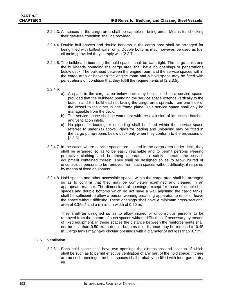
PART 9-F CHAPTER 3 IRS Rules for Building and Classing Steel Vessels
192 INTERNATIONAL REGISTER OF SHIPPING
2.2.4.3. All spaces in the cargo area shall be capable of being aired. Means for checking
their gas-free condition shall be provided. 2.2.4.4. Double hull spaces and double bottoms in the cargo area shall be arranged for
being filled with ballast water only. Double bottoms may, however, be used as fuel oil tanks, provided they comply with [2.2.7].
2.2.4.5. The bulkheads bounding the hold spaces shall be watertight. The cargo tanks and
the bulkheads bounding the cargo area shall have no openings or penetrations below deck. The bulkhead between the engine room and the service spaces within the cargo area or between the engine room and a hold space may be fitted with penetrations on condition that they fulfill the requirements of [2.2.3.5].
2.2.4.6.
a) A space in the cargo area below deck may be decided as a service space, provided that the bulkhead bounding the service space extends vertically to the bottom and the bulkhead not facing the cargo area spreads from one side of the vessel to the other in one frame plane. This service space shall only be manageable from the deck.
b) The service space shall be watertight with the exclusion of its access hatches and ventilation inlets.
c) No pipes for loading or unloading shall be fitted within the service space referred to under (a) above. Pipes for loading and unloading may be fitted in the cargo pump-rooms below deck only when they conform to the provisions of [2.3.6].
2.2.4.7. In the cases where service spaces are located in the cargo area under deck, they
shall be arranged so as to be easily reachable and to permit persons wearing protective clothing and breathing apparatus to safely operate the service equipment contained therein. They shall be designed so as to allow injured or unconscious persons to be removed from such spaces without difficulty, if required by means of fixed equipment.
2.2.4.8. Hold spaces and other accessible spaces within the cargo area shall be arranged
so as to confirm that they may be completely examined and cleaned in an appropriate manner. The dimensions of openings, except for those of double hull spaces and double bottoms which do not have a wall adjoining the cargo tanks, shall be sufficient to allow a person wearing breathing apparatus to enter or leave the space without difficulty. These openings shall have a minimum cross-sectional
area of 0.36𝑚2 and a minimum width of 0.50 m.
They shall be designed so as to allow injured or unconscious persons to be removed from the bottom of such spaces without difficulties, if necessary by means of fixed equipment. In these spaces the distance between the reinforcements shall not be less than 0.50 m. In double bottoms this distance may be reduced to 0.45 m. Cargo tanks may have circular openings with a diameter of not less than 0.7 m.
2.2.5. Ventilation
2.2.8.1. Each hold space shall have two openings the dimensions and location of which
shall be such as to permit effective ventilation of any part of the hold space. If there are no such openings, the hold spaces shall probably be filled with inert gas or dry air.
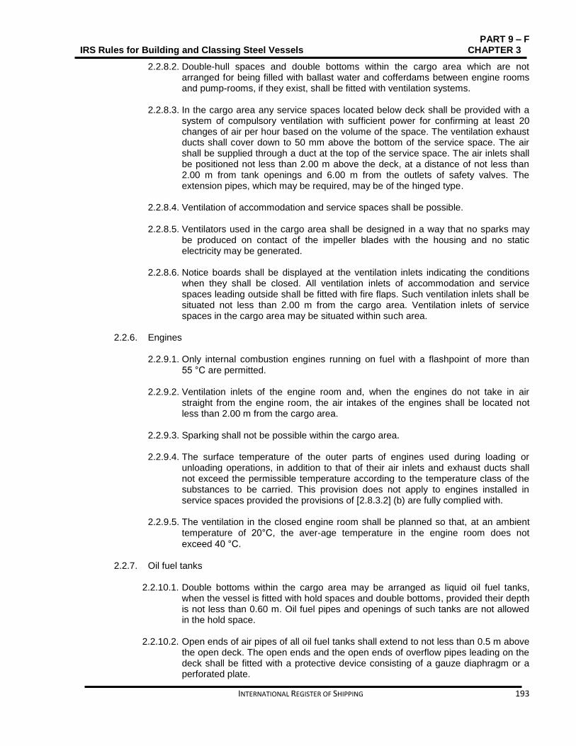
PART 9 – F IRS Rules for Building and Classing Steel Vessels CHAPTER 3
INTERNATIONAL REGISTER OF SHIPPING 193
2.2.8.2. Double-hull spaces and double bottoms within the cargo area which are not arranged for being filled with ballast water and cofferdams between engine rooms and pump-rooms, if they exist, shall be fitted with ventilation systems.
2.2.8.3. In the cargo area any service spaces located below deck shall be provided with a
system of compulsory ventilation with sufficient power for confirming at least 20 changes of air per hour based on the volume of the space. The ventilation exhaust ducts shall cover down to 50 mm above the bottom of the service space. The air shall be supplied through a duct at the top of the service space. The air inlets shall be positioned not less than 2.00 m above the deck, at a distance of not less than 2.00 m from tank openings and 6.00 m from the outlets of safety valves. The extension pipes, which may be required, may be of the hinged type.
2.2.8.4. Ventilation of accommodation and service spaces shall be possible.
2.2.8.5. Ventilators used in the cargo area shall be designed in a way that no sparks may
be produced on contact of the impeller blades with the housing and no static electricity may be generated.
2.2.8.6. Notice boards shall be displayed at the ventilation inlets indicating the conditions
when they shall be closed. All ventilation inlets of accommodation and service spaces leading outside shall be fitted with fire flaps. Such ventilation inlets shall be situated not less than 2.00 m from the cargo area. Ventilation inlets of service spaces in the cargo area may be situated within such area.
2.2.6. Engines
2.2.9.1. Only internal combustion engines running on fuel with a flashpoint of more than
55 °C are permitted. 2.2.9.2. Ventilation inlets of the engine room and, when the engines do not take in air
straight from the engine room, the air intakes of the engines shall be located not less than 2.00 m from the cargo area.
2.2.9.3. Sparking shall not be possible within the cargo area. 2.2.9.4. The surface temperature of the outer parts of engines used during loading or
unloading operations, in addition to that of their air inlets and exhaust ducts shall not exceed the permissible temperature according to the temperature class of the substances to be carried. This provision does not apply to engines installed in service spaces provided the provisions of [2.8.3.2] (b) are fully complied with.
2.2.9.5. The ventilation in the closed engine room shall be planned so that, at an ambient
temperature of 20°C, the aver-age temperature in the engine room does not
exceed 40 °C.
2.2.7. Oil fuel tanks
2.2.10.1. Double bottoms within the cargo area may be arranged as liquid oil fuel tanks, when the vessel is fitted with hold spaces and double bottoms, provided their depth is not less than 0.60 m. Oil fuel pipes and openings of such tanks are not allowed in the hold space.
2.2.10.2. Open ends of air pipes of all oil fuel tanks shall extend to not less than 0.5 m above
the open deck. The open ends and the open ends of overflow pipes leading on the deck shall be fitted with a protective device consisting of a gauze diaphragm or a perforated plate.

PART 9-F CHAPTER 3 IRS Rules for Building and Classing Steel Vessels
194 INTERNATIONAL REGISTER OF SHIPPING
2.2.8. Exhaust pipes
2.2.11.1. Exhausts shall be banished from the vessel into the open air either upwards through an exhaust pipe or through the shell plating. The exhaust outlet shall be positioned not less than 2 m from the cargo area. The exhaust pipes of engines shall be settled so that the exhausts are led away from the vessel. The exhaust pipes shall not be located within the cargo area.
2.2.11.2. Exhaust pipes shall be provided with a device preventing the escape of sparks, e.g.
spark arresters.
2.2.9. Bilge pumping and ballasting arrangements
2.2.12.1. Bilge and ballast pumps for spaces within the cargo area shall be installed within such area.
This provision does not apply to:
Double-hull spaces and double bottoms which do not have a common boundary wall with the cargo tanks;
Cofferdams and hold spaces where ballasting is carried out using the piping of the firefighting system in the cargo area and bilge-pumping is performed using eductors.
2.2.12.2. It shall not be connected to the bilge piping system where the double bottom is
used as a liquid oil fuel tank.
2.2.12.3. The standpipe and its outboard connection for suction of ballast water shall be situated within the cargo area where the ballast pump is installed in the cargo area.
2.2.12.4. It shall be possible for an under-deck pump room to be exposed in an emergency
using a system located in the cargo area and independent of any other system. This stripping system shall be located outside the pump-room.
2.2.10. Ventilation of cargo pump rooms and gas compressor rooms
2.2.13.1. Independent of other vessel's spaces, providing at least 30 cycles of air change per
hour Cargo pump and compressor rooms must be providing with extraction type ventilation systems. Warning notices shall be placed requiring that the ventilation is in operation for at least 15 minutes prior to entering these spaces.
2.2.13.2. Portable means must be provided for gas-freeing of cargo tanks and other spaces
not equipped with fixed ventilation.
2.3. Cargo containment
2.3.1. Cargo area hull design
2.3.1.1. General According to the following requirements in the cargo area, the vessel shall be designed either as a double hull and double bottom vessel, or as a single hull vessel. Alternative constructions in accordance with Chapter 3, ****** are permitted.
2.3.1.2. Double hull vessel
Vessels with double hull and double bottom shall fulfill the following:

PART 9 – F IRS Rules for Building and Classing Steel Vessels CHAPTER 3
INTERNATIONAL REGISTER OF SHIPPING 195
The internal distance between the side platings of the vessel and the longitudinal bulkheads shall not be less than 0.80 m
The height of the double bottom shall not be less than 0.60 m.
The cargo tanks shall be supported by saddles extending between the tanks to not less than 20° below the horizontal centreline of the cargo tanks.
2.3.1.3. Single hull vessel
Single hull vessel shall fulfill the following:
It shall be fitted with side platings between gangboard and top of floor plates on condition that side stringers are placed at intervals of not more than 0.60 m and are supported by web frames spaced at intervals of not more than 2.00 m
The side stringers and the web frames shall have a height of not less than 10% of the vessel depth, however, not less than 0.30 m
The side stringers and web frames shall be fitted with a face plate made of
steel and having a cross section of not less than 7.5 cm2 and 15
cm2 respectively
The distance between the side plating of the vessel and the cargo tanks shall be not less than 0.80 m and between the bottom and the cargo tanks not less than 0.60 m. the depth below the suction wells may be reduced to 0.50 m
The lateral distance between the suction well of the cargo tanks and the bottom structure shall be not less than 0.10 m.
The cargo tank supports and fastenings should extend to not less than 10° below the horizontal centreline of the cargo tanks.
2.3.1.4. Side-struts linking or supporting the load-bearing components of the sides of the
vessel with the load bearing components of the longitudinal walls of cargo tanks and side struts linking the load-bearing components of the vessel’s bottom with the tank bottom are banned.
2.3.2. Cargo tank sizes
2.3.2.1. In accordance with Table 3.2. 2 the maximum allowable capacity of a cargo tank
for single hull tank vessels, double hull tank vessels and vessels with tanks independent of the hull shall be determined. where: LOAB D: Product of the tank vessel main dimensions, in m3
LOA ∶ overall length of the hull, in m In the case of trunk deck vessels, D’ is to be substituted for D. D’ is to be determined by the following formula:
D'= D + h
btlt
𝐵𝐿𝑂𝐴
where: ht: Height, in m, of trunk (distance between trunk deck and main deck on trunk
side measured at LOA/2)
bt: Trunk breadth, in ml lt: Trunk length, in m
2.3.2.2. Substitute constructions will be allowed on a case to case basis are allowed.
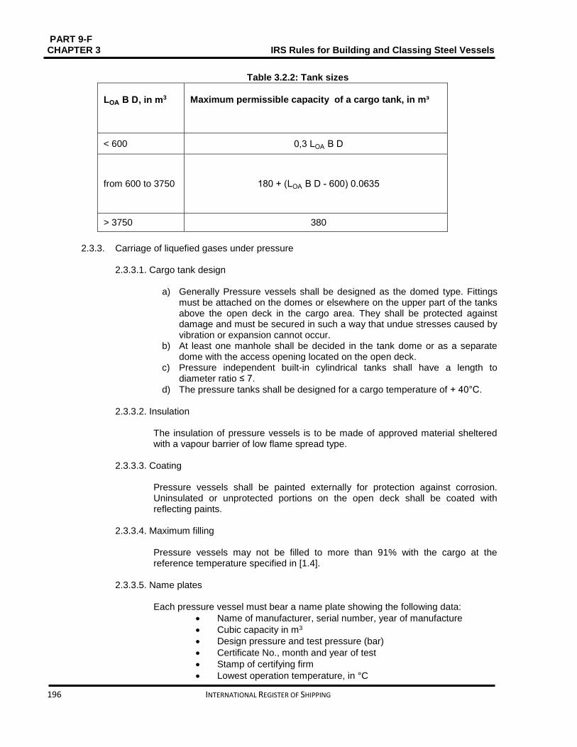
PART 9-F CHAPTER 3 IRS Rules for Building and Classing Steel Vessels
196 INTERNATIONAL REGISTER OF SHIPPING
Table 3.2.2: Tank sizes
LOA B D, in m3
Maximum permissible capacity of a cargo tank, in m³
< 600 0,3 LOA B D
from 600 to 3750 180 + (LOA B D - 600) 0.0635
> 3750 380
2.3.3. Carriage of liquefied gases under pressure
2.3.3.1. Cargo tank design
a) Generally Pressure vessels shall be designed as the domed type. Fittings
must be attached on the domes or elsewhere on the upper part of the tanks above the open deck in the cargo area. They shall be protected against damage and must be secured in such a way that undue stresses caused by vibration or expansion cannot occur.
b) At least one manhole shall be decided in the tank dome or as a separate dome with the access opening located on the open deck.
c) Pressure independent built-in cylindrical tanks shall have a length to diameter ratio ≤ 7.
d) The pressure tanks shall be designed for a cargo temperature of + 40°C.
2.3.3.2. Insulation The insulation of pressure vessels is to be made of approved material sheltered with a vapour barrier of low flame spread type.
2.3.3.3. Coating
Pressure vessels shall be painted externally for protection against corrosion. Uninsulated or unprotected portions on the open deck shall be coated with reflecting paints.
2.3.3.4. Maximum filling Pressure vessels may not be filled to more than 91% with the cargo at the reference temperature specified in [1.4].
2.3.3.5. Name plates
Each pressure vessel must bear a name plate showing the following data:
Name of manufacturer, serial number, year of manufacture
Cubic capacity in m3
Design pressure and test pressure (bar)
Certificate No., month and year of test
Stamp of certifying firm
Lowest operation temperature, in °C

PART 9 – F IRS Rules for Building and Classing Steel Vessels CHAPTER 3
INTERNATIONAL REGISTER OF SHIPPING 197
Vapour pressure, in bar at reference temperature, in °C.
The name plates must be clear from the deck.
2.3.4. Carriage of liquefied gases at atmospheric pressure
2.3.4.1. Requirements as set out in ADN Rules are to be observed. In accordance with the provisions for liquefied gas tankers laid down in the Society's Rules further individual requirements are to be decided in discussion with the Society on a case by case basis.
2.3.4.2. Refrigerated cargo tanks shall be connected only in hold spaces bounded by
double hull spaces and double bottom.
2.3.5. Cargo tank openings
2.3.5.1. a) Cargo tank openings shall be situated on deck in the cargo area.
b) Cargo tank openings with a cross-section greater than 0.10 m2shall be located not less than 0.50 m above the deck.
2.3.5.2. The exhaust outlets of the pressure relief valves shall be situated not less than
2.00 m above the deck at a distance of not less than 6.00 m from the lodging and from the service spaces located outside the cargo area. This height may be reduced when within a radius of 1.00 m round the pressure relief valve outlet there is no equipment, no work is being performed and signs indicate the area.
2.3.5.3. The closing devices usually used in loading and unloading operations shall not be
capable of producing sparks when operated. 2.3.5.4. Each tank in which refrigerated materials are carried shall be equipped with a
safety system to prevent unauthorized vacuum or overpressure.
2.4. Cargo piping system
2.4.1. General
2.4.1.1. Pumps, compressors and addition loading and unloading piping shall be located in the cargo area. Cargo pumps and compressors shall be capable of being shut down from the cargo area and, additionally, from a position outside the cargo area. Cargo pumps and compressors situated on deck shall be located not less than 6.00 m from entrances to, or openings of, the accommodation and service spaces outside the cargo area.
2.4.2. Arrangement of cargo piping
2.4.2.1. Pipes for loading and unloading shall be independent of any other piping of the
vessel. No cargo piping shall be located below deck, except those inside the cargo tanks and in the service spaces intended for the installation of the vessel’s own gas discharging system.
2.4.2.2. Pipes for loading and unloading shall be clearly distincted from other piping, e.g. by
means of colour marking.
2.4.2.3. The pipes for loading and unloading on deck, the vapour pipes with the exclusion of the shore connections but including the safety valves, and the valves shall be
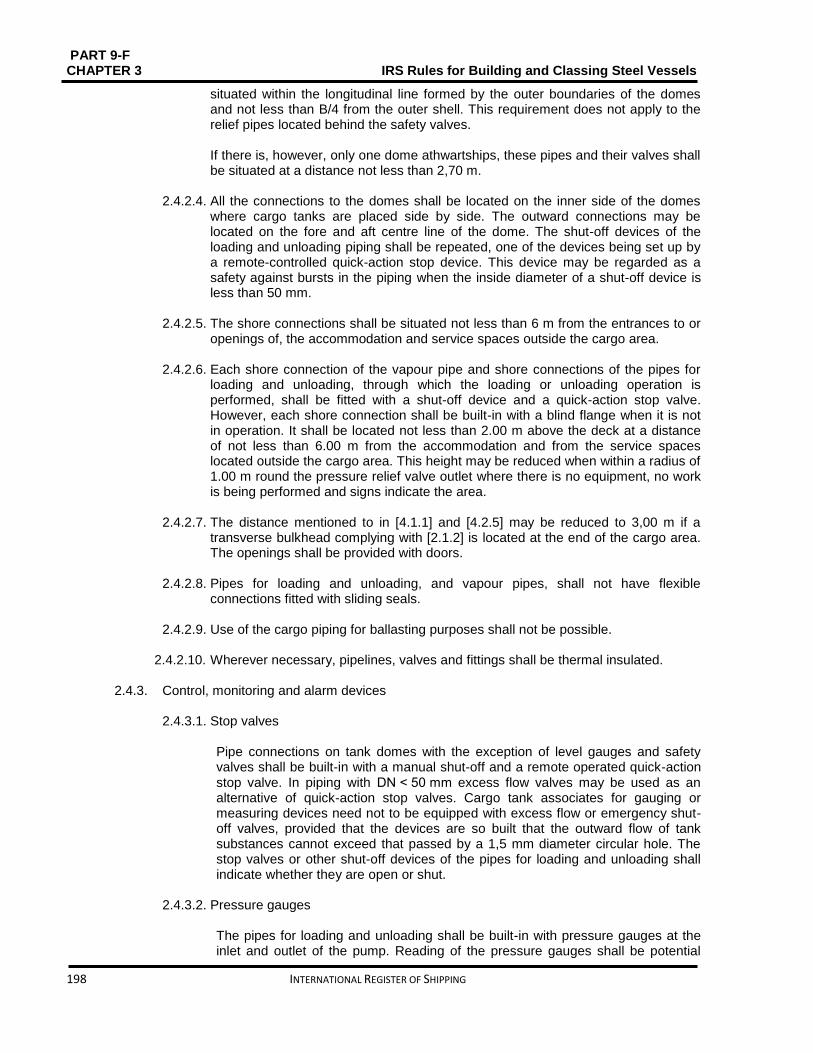
PART 9-F CHAPTER 3 IRS Rules for Building and Classing Steel Vessels
198 INTERNATIONAL REGISTER OF SHIPPING
situated within the longitudinal line formed by the outer boundaries of the domes and not less than B/4 from the outer shell. This requirement does not apply to the relief pipes located behind the safety valves.
If there is, however, only one dome athwartships, these pipes and their valves shall be situated at a distance not less than 2,70 m.
2.4.2.4. All the connections to the domes shall be located on the inner side of the domes
where cargo tanks are placed side by side. The outward connections may be located on the fore and aft centre line of the dome. The shut-off devices of the loading and unloading piping shall be repeated, one of the devices being set up by a remote-controlled quick-action stop device. This device may be regarded as a safety against bursts in the piping when the inside diameter of a shut-off device is less than 50 mm.
2.4.2.5. The shore connections shall be situated not less than 6 m from the entrances to or
openings of, the accommodation and service spaces outside the cargo area.
2.4.2.6. Each shore connection of the vapour pipe and shore connections of the pipes for loading and unloading, through which the loading or unloading operation is performed, shall be fitted with a shut-off device and a quick-action stop valve. However, each shore connection shall be built-in with a blind flange when it is not in operation. It shall be located not less than 2.00 m above the deck at a distance of not less than 6.00 m from the accommodation and from the service spaces located outside the cargo area. This height may be reduced when within a radius of 1.00 m round the pressure relief valve outlet where there is no equipment, no work is being performed and signs indicate the area.
2.4.2.7. The distance mentioned to in [4.1.1] and [4.2.5] may be reduced to 3,00 m if a
transverse bulkhead complying with [2.1.2] is located at the end of the cargo area. The openings shall be provided with doors.
2.4.2.8. Pipes for loading and unloading, and vapour pipes, shall not have flexible
connections fitted with sliding seals.
2.4.2.9. Use of the cargo piping for ballasting purposes shall not be possible.
2.4.2.10. Wherever necessary, pipelines, valves and fittings shall be thermal insulated.
2.4.3. Control, monitoring and alarm devices
2.4.3.1. Stop valves Pipe connections on tank domes with the exception of level gauges and safety valves shall be built-in with a manual shut-off and a remote operated quick-action stop valve. In piping with DN < 50 mm excess flow valves may be used as an alternative of quick-action stop valves. Cargo tank associates for gauging or measuring devices need not to be equipped with excess flow or emergency shut-off valves, provided that the devices are so built that the outward flow of tank substances cannot exceed that passed by a 1,5 mm diameter circular hole. The stop valves or other shut-off devices of the pipes for loading and unloading shall indicate whether they are open or shut.
2.4.3.2. Pressure gauges The pipes for loading and unloading shall be built-in with pressure gauges at the inlet and outlet of the pump. Reading of the pressure gauges shall be potential
PART 9 – F IRS Rules for Building and Classing Steel Vessels CHAPTER 3
INTERNATIONAL REGISTER OF SHIPPING 199
from the control position of the vessel’s own gas discharging system. The maximum permissible overpressure or vacuum shall be specified by a red mark. Readings shall be possible in all weather conditions.
2.4.4. Bonding Each component of the pipes for loading and unloading shall be electrically connected to the hull.
2.5. Cargo pressure and temperature control
2.5.1. Regulation of cargo pressure and temperature
2.5.1.1. If not the entire cargo system is planned to resist the full effective vapour pressure of the cargo at the upper limits of the ambient design temperatures, the pressure of the tanks shall be kept below the allowable maximum set pressure of the safety valves, by one or more of the following means:
A system for the regulation of cargo tank pressure using mechanical refrigeration
A system confirming safety in the event of the heating or increase in pressure of the cargo. The insulation or the design pressure of the cargo tank, or the combination of these two elements, shall be such as to leave an adequate margin for the operating period and the temperatures expected; in each case the system shall be considered acceptable by the Society and shall ensure safety for a minimum time of three times the operation period
The Society shall accept the other systems.
2.5.1.2. The systems suggested in [5.1.1] shall be constructed, installed and tested to the satisfaction of the Society. The materials used in their construction shall be well-matched with the cargoes to be carried. For normal service, the upper ambient design temperature limits shall be:
air: + 30°C
water:+ 20°C
2.5.1.3. The cargo storage system shall be capable of resisting the full vapour pressure of the cargo at the upper limits of the ambient design temperatures, whatever the system adopted to deal with the boil-off gas. This requirement is indicated by remark 37 in column (20) of Table C of ADN Chapter 3.2.
2.5.2. Refrigeration system
2.5.2.1. The refrigeration system referred to in [5.1.1] shall be collected of one or more
units proficient enough of keeping the pressure and temperature of the cargo at the upper limits of the ambient design temperatures at the recommended level. Unless another means of regulating cargo pressure and temperature thought satisfactory by the Society is provided, provision shall be made for one or more stand-by units with an output at least equal to that of the largest prescribed unit. A stand-by unit shall comprise a compressor, its engine, its control system and all necessary accessories to enable it to operate independently of the units normally used. Provision shall be made for a stand-by heat-exchanger unless the system’s normal heat-exchanger has a surplus capacity equal to at least 25% of the largest prescribed capacity. It is not necessary to make provision for separate piping.

PART 9-F CHAPTER 3 IRS Rules for Building and Classing Steel Vessels
200 INTERNATIONAL REGISTER OF SHIPPING
Cargo tanks, piping and accessories shall be insulated so that, in the event of a failure of all cargo refrigeration systems, the entire cargo remains for at least 52 hours in a condition not causing the safety valves to open.
2.5.2.2. The security devices and the connecting lines from the refrigeration system shall
be linked to the cargo tanks above the liquid phase of the cargo when the tanks are filled to their maximum allowable degree of filling. They shall keep on within the gaseous phase, even if the vessel has a list up to 12 degrees.
2.5.2.3. Individual care shall be given to the refrigeration systems so as to stop any mixing
of the cargoes when several refrigerated cargoes with a potentially dangerous chemical reaction are carried at the same time. For the carriage of such cargoes, separate refrigeration systems, each including the full stand-by unit referred to in [5.2.1], shall be provided for each cargo. When, however, an indirect or combined system and no leak in the heat exchangers ensure the refrigeration and it shall be can under any foreseeable circumstances lead to the mixing of cargoes, no provision need be made for separate refrigeration units for the different cargoes.
2.5.2.4. Particular care shall be given to the refrigeration systems to prevent any mixing of
the cargoes when several refrigerated cargoes are not solvable in each other under conditions of carriage such that their vapour pressures are added together in the event of mixing.
2.5.2.5. A sufficient quantity shall be supplied by a pump or pumps used completely for the
purpose when the refrigeration systems require water for cooling. This pump or pumps shall have at least two suction pipes leading from two water intakes, one to port, the other to starboard. Provision shall be made for a stand-by pump with a satisfactory flow; this may be a pump used for other determinations provided that its use for supplying water for cooling does not damage any other essential service.
2.5.2.6. The refrigeration system may take one of the following forms:
a) Direct system: the cargo vapours are compressed, condensed and returned
to the cargo tanks. This system shall not be used for certain cargoes specified in Table C of ADN Regulations Chapter 3.2. This requirement is indicated by remark 35 in column (20) of Table C of ADN Regulations Chapter 3.2
b) Indirect system: The cargo or the cargo vapours are cooled or condensed by means of a coolant without being compressed
c) Combined system: The cargo vapours are compressed and condensed in a cargo/coolant heat-exchanger and returned to the cargo tanks. This system shall not be used for certain cargoes specified in Table C of ADN Regulations Chapter 3.2. This requirement is indicated by remark 36 in column (20) of Table C of ADN Regulations Chapter 3.2.
2.5.2.7. All primary and secondary coolant fluids shall be compatible with each other and
with the cargo with which they may come into contact. Heat exchange may take place either at a distance from the cargo tank, or by using cooling coils attached to the inside or the outside of the cargo tank.
2.5.2.8. This service space shall meet the requirements of [2.3.6] when the refrigeration
system is installed in a separate service space. 2.5.2.9. The heat transmission coefficient shall be determined by calculation for all cargo
systems. The correctness of the calculation shall be checked by means of a refrigeration test (heat balance test). In accordance with the requirements set up by the Society this test shall be performed.

PART 9 – F IRS Rules for Building and Classing Steel Vessels CHAPTER 3
INTERNATIONAL REGISTER OF SHIPPING 201
2.5.3. Water spray system
2.5.3.1. A water spray system shall be fixed in the cargo area on deck for the purpose of
reducing gases given off by the cargo by spraying water when water spraying is required in column (9) of Table C of ADN Regulations Chapter 3.2.
2.5.3.2. The system shall be fixed with a connection device for supply from the shore. The
spray nozzles shall be fixed in such way that released gases are precipitated safely. The system shall be proficient enough of being put into operation from the wheelhouse and from the deck. The capacity of the water-spray system shall be such that when all the spray nozzles are in operation, the outflow is not less than 50 litres per square metre of cargo deck area and per hour.
2.6. Pressure cargo tank venting system
2.6.1. Safety valves 2.6.1.1. The highest part of the vapour space (tank dome) of pressure vessels with a
capacity of less than 20 m3 is to be built-in with at least one, and pressure vessels
with a capability of more than 20 m3 two independent, spring loaded safety valves. Taking into account the vessel's trim and list means must be provided to prevent the accumulation of liquid cargo in the pipe upstream to the safety valves.
2.6.2. Discharge capacity of safety valves 2.6.2.1. The total discharge capacity of the safety valves shall be as per the formula here
below. During blowing down the pressure in the tank shall not rise more than 20% above the maximum allowable relief valve setting (MARVS).
Q = F G A0,82
Where: Q ∶ Minimum required equivalent discharge rate of air, in m3/s, at standard conditions of 273°K and 1,013 bar F ∶ Fire exposure factor for different cargo tank types:
F = 1,0 for uninsulated tanks located on deck
F = 0,5 for tanks above the deck when insulation is approved by the society. (Approval will be based on the use of an approved fire proofing material, the thermal conductance of insulation, and its stability under fire exposure)
F = 0,5 for uninsulated independent tanks installed in holds
F = 0,2 for insulated independent tanks in holds (or uninsulated independent tanks in insulated holds)
F = 0,1 for insulated independent tanks in inerted holds (or uninsulated independent tanks in inerted, insulated holds) For independent tanks partly protruding through the open deck, the fire exposure factor is to be determined on the basis of the surface areas above and below deck. G ∶ Gas factor defined as:
G= 12,4
r D√
ZT
M
where: T ∶ Temperature in K = (273 + °C) at the relieving conditions, i.e. 120% of the setting pressure

PART 9-F CHAPTER 3 IRS Rules for Building and Classing Steel Vessels
202 INTERNATIONAL REGISTER OF SHIPPING
r : Latent heat of the material being vaporized at relieving conditions, in kJ/kg D ∶ Constant based on relation of specific heats (k), shown in Table 3.2.3; if
k is not known, D = 0,606 shall be used.
The constant D may also be calculated by the following formula:
D= √k (2
k+1)
k+1k-1
Z : Compressibility factor of the gas at relieving conditions; if not known, Z = 1,0 shall be used
M : Molecular weight of the product
Table 3.2.3: Constant D
𝒌 𝑫 𝒌 𝑫
1,00 0,606 1,52 0,704
1,02 0,611 1,54 0,707
1.04 0,615 1,56 0,710
1,06 0,620 1,58 0,713
1,08 0,624 1,60 0,716
1,10 0,628 1,62 0,719
1,12 0,633 1,64 0,722
1,14 0,637 1,66 0,725
1,16 0,641 1,68 0,728
1,18 0,645 1,70 0,731
1,20 0,649 1,72 0,734
1,22 0,652 1,74 0,736
1,24 0,656 1,76 0,739
1,26 0,660 1,78 0,742
1,28 0,664 1,80 0,745
1,30 0,667 1,82 0,747
1,32 0,671 1,84 0,750
1,34 0,674 1,86 0,752
1,36 0,677 1,88 0,755
1,38 0,681 1,90 0,758
1,40 0,685 1,92 0,760
1,42 0,688 1,94 0,763
1,44 0,691 1,96 0,765
1,46 0,695 1,98 0,767
1,48 0,698 2,00 0,770
1,50 0,701 2,02 0,772
2,20 0,792
A : External surface area of the tank in, m2, for different tank types
for body of revolution type tanks, A = external surface area for other than bodies of revolution type tanks,
A external surface area less the projected bottom surface area
for tanks consisting of an array of pressure vessels tanks, A = external surface area of the hold less its projected bottom area.
insulation on the tank structure, A = external surface area of the array of pressure vessels excluding insulation, less the projected bottom area as shown in Fig 1.

PART 9 – F IRS Rules for Building and Classing Steel Vessels CHAPTER 3
INTERNATIONAL REGISTER OF SHIPPING 203
Figure 3.2.1: Array of pressure vessel tanks
2.6.2.2. The setting of the pressure relief valves is not to be higher than the maximum pressure for which the cargo tank is designed.
2.6.2.3. It is suggested that a device may be fixed allowing one safety valve at a time to be isolated for a short period for repair/maintenance. In this case, though, at least half the required safety valve cross-section must keep on operative.
2.6.3. Safety valves blow-off lines 2.6.3.1. The blow-off lines of pressure vessel safety valves may be prepared individual or
with common headers. The outlets are to be arranged at least 2 m above deck at a horizontal distance of 6 m from lodging space or other safe spaces. The height may be reduced to less than 2 m in case the area of 1 m around the high velocity valve is planned as non-accessible.
2.6.3.2. The total cross-section of the blow-off piping must be satisfactory enough to discharge safely the quantity of gas calculated in [6.2].
2.7. Environmental control
2.7.1. Inerting facility
2.7.1.1. The vessel shall be equipped with an inerting system in cases in which inerting or blanketing of the cargo is prescribed.
2.7.1.2. This system shall be accomplished of maintaining a permanent minimum pressure
of 7 kPa (0,07 bar) in the spaces to be inerted. Additionally, the inerting system shall not escalate the pressure in the cargo tank to a pressure greater than that at which the pressure valve is controlled. The set pressure of the vacuum-relief valve shall be 3,5 kPa (0.035 bar).
2.7.1.3. A sufficient quantity of inert gas for loading or unloading shall be carried or
produced on board if it is not possible to obtain it on shore. In addition, a sufficient quantity of inert gas to offset normal losses occurring during carriage shall be on board.
2.7.1.4. The premises to be inerted shall be equipped with connections for introducing the
inert gas and monitoring systems so as to ensure the correct atmosphere on a permanent basis.
2.7.1.5. When the pressure or the attention of inert gas in the gaseous phase falls below a
given value, this monitoring system shall activate an audible and visible alarm in the wheelhouse. When the wheelhouse is unoccupied, the alarm shall also be perceptible in a location occupied by a crew member.

PART 9-F CHAPTER 3 IRS Rules for Building and Classing Steel Vessels
204 INTERNATIONAL REGISTER OF SHIPPING
2.8. Electrical installations
2.8.1. Documents to be kept on board
2.8.8.1. In addition to the documents required in Part E Chapter 1 the following documents
shall be on board:
a) a drawing indicating the boundaries of the cargo area and the location of the electrical equipment installed in this area.
b) a list of the electrical equipment referred to in (a) above including the following particulars: machine or appliance, location, type of protection, type of protection against explosion, testing body and approval number.
c) a list of or general plan indicating the electrical equipment outside the cargo area which may be operated during loading, unloading or gas-freeing. All other electrical equipment shall be marked in red. See [2.8.3.2],[2.8.3.3].
2.8.2. General design requirements
2.8.2.1. Only distribution systems without return connection to the hull are permitted. This provision does not apply to:
local installations outside the cargo area (e.g. connections of starters of diesel engines)
device for checking the insulation level referred to in [2.8.2.2]
active cathodic corrosion protection.
2.8.2.2. Every insulated distribution network shall be fitted with an automatic device with a visual and audible alarm for checking the insulation level.
2.8.2.3. For the selection of electrical equipment to be used in zones presenting an
explosion risk, the explosion groups and temperature classes assigned to the substances carried in the list of substances shall be taken into consideration(See column (15) and (16) of Table C of ADN Regulations Chapter 3.2).
2.8.3. Type and location of electrical equipment
2.8.3.1.
a) Only measuring, regulation and alarm devices of the EEx (ia) type of protection may be installed in cargo tanks and pipes for loading and unloading (comparable to zone 0)
b) Only the following equipment may be installed in the cofferdams, double hull spaces, double bottoms and hold spaces (comparable to zone 1):
measuring, regulation and alarm devices of the certified safe type
lighting appliances of the “flame-proof enclosure” or “apparatus protected by pressurization” type of protection
hermetically sealed echo sounding devices the cables of which are led through thick-walled steel tubes with gastight connections up to the main deck
cables for the active cathodic protection of the shell plating in protective steel tubes such as those pro-vided for echo sounding devices.
c) Only the following equipment may be installed in the service spaces in the cargo area
below deck (comparable to zone 1):

PART 9 – F IRS Rules for Building and Classing Steel Vessels CHAPTER 3
INTERNATIONAL REGISTER OF SHIPPING 205
measuring, regulation and alarm devices of the certified safe type
lighting appliances of the “flame-proof enclosure” or “apparatus protected by pressurization” type of protection
motors driving essential equipment such as ballast pumps; they shall be of the certified safe type.
d) The control and protective equipment of the electrical equipment referred to in (a), (b)
and (c) above shall be located outside the cargo area if they are not intrinsically safe.
e) The electrical equipment in the cargo area on deck (comparable to zone 1) shall be of the certified safe type.
2.8.3.2.
a) Electrical equipment used during loading, unloading and gas-freeing during berthing and which are located outside the cargo area (comparable to zone 2) shall be at least of the “limited explosion risk” type.
b) This provision does not apply to:
lighting installations in the accommodation, except for switches near entrances to accommodation
radiotelephone installations in the accommodation or the wheelhouse
mobile and fixed telephone installations in the accommodation or the wheelhouse
electrical installations in the accommodation, the wheelhouse or the service spaces outside the cargo areas if:
These spaces are fitted with a ventilation system ensuring an overpressure of 0,1 kPa (0,001 bar) and none of the windows is capable of being opened; the air intakes of the ventilation system located as far away as possible, however, not less than 6,00 m from the cargo area and not less than 2,00 m above the deck
The spaces are fitted with a gas detection system with sensors:
- at the suction inlets of the ventilation system - directly at the top edge of the sill of the entrance doors of the
accommodation and service spaces
The gas concentration measurement is continuous
When the gas concentration reaches 20% of the lower explosive limit, the ventilators shall be switched off. In such a case and when the over-pressure is not maintained or in the event of failure of the gas detection system, the electrical installations which do not comply with (a) above, shall be switched off. These operations shall be performed immediately and automatically and activate the emergency lighting in the accommodation, the wheelhouse and the ser-vice spaces, which shall comply at least with the “limited explosion risk” type. The switching-off shall be indicated in the accommodation and wheelhouse by visual and audible signals
The ventilation system, the gas detection system and the alarm of the switch-off device fully com-ply with the requirements of (a) above
The automatic switch-off device is set so that no automatic switching-off may occur while the vessel is under way.
2.8.3.3. The electrical equipment which does not meet the requirements set out in [8.3.2]
together with its switches shall be marked in red. The disconnection of such equipment shall be operated from a centralized location on board.

PART 9-F CHAPTER 3 IRS Rules for Building and Classing Steel Vessels
206 INTERNATIONAL REGISTER OF SHIPPING
2.8.3.4. An electric generator which is permanently driven by an engine and which does
not meet the requirements of [2.8.3.2], shall be fitted with a switch capable of shutting down the excitation of the generator. A notice board with the operating instructions shall be displayed near the switch.
2.8.3.5. Sockets for the connection of signal lights and gang-way lighting shall be
permanently fitted to the vessel close to the signal mast or the gangway. Connecting and disconnecting shall not be possible except when the sockets are not live.
2.8.3.6. The failure of the power supply for the safety and control equipment shall be
immediately indicated by visual and audible signals at the locations where the alarms are usually actuated.
2.8.4. Earthing
2.8.4.1. The metal parts of electrical appliances in the cargo area which are not live as well
as protective metal tubes or metal sheaths of cables in normal service shall be earthed, unless they are so arranged that they are automatically earthed by bonding to the metal structure of the vessel.
2.8.4.2. The provisions of [8.4.1] apply also to equipment having service voltages of less
than 50 V.
2.8.4.3. Independent cargo tanks shall be earthed.
2.8.4.4. Receptacles for residual products shall be capable of being earthed.
2.8.5. Electrical cables
2.8.5.1. All cables in the cargo area shall have a metallic sheath. 2.8.5.2. Cables and sockets in the cargo area shall be protected against mechanical
damage.
2.8.5.3. Movable cables are prohibited in the cargo area, except for intrinsically safe electric circuits or for the supply of signal lights and gangway lighting.
2.8.5.4. Cables of intrinsically safe circuits shall only be used for such circuits and shall be
separated from other cables not intended for being used in such circuits (e.g. they shall not be installed together in the same string of cables and they shall not be fixed by the same cable clamps).
2.8.5.5. For movable cables intended for signal lights and gangway lighting, only sheathed
cables of type H 07 RN-F in accordance with standard IEC 60 245-4:1994 or cables of at least equivalent design having conductors with a cross-section of not
less than 1,5 mm2 shall be used. These cables shall be as short as possible and installed so that damage is not likely to occur.
2.8.6. Storage batteries
Storage batteries shall be located outside the cargo area.

PART 9 – F IRS Rules for Building and Classing Steel Vessels CHAPTER 3
INTERNATIONAL REGISTER OF SHIPPING 207
2.9. Fire protection and fire extinction
2.9.1. Fire and naked light
2.9.1.1. The outlets of funnels shall be located not less than 2.00 m from the cargo area. Arrangements shall be provided to prevent the escape of sparks and the entry of water.
2.9.1.2. Heating, cooking and refrigerating appliances shall not be fuelled with liquid fuels,
liquid gas or solid fuels. The installation in the engine room or in another separate space of heating appliances fuelled with liquid fuel having a flash-point above 55°C is, however, permitted. Cooking and refrigerating appliances are permitted only in the accommodation.
2.9.1.3. Only electrical lighting appliances are permitted.
2.9.2. Prohibition of smoking, fire or naked light
2.9.2.1. The notice boards displaying the prohibition of smoking in accordance with ADN
Regulations Section 8.3.4 shall be clearly legible from either side of the vessel.
2.9.2.2. Notice boards indicating the circumstances under which the prohibition is applicable shall be fitted near the entrances to the spaces where smoking or the use of fire or naked light is not always prohibited.
2.9.3. Fire extinguishing arrangements
In addition to the requirements of Part C, Chapter 3, the fire extinguishing arrangements in [2.9.4] to [2.9.6] are to be complied with.
2.9.4. Portable fire extinguishers In addition to the fire-extinguishing appliances pre-scribed in Part D, Chapter 2, Sec 2, [2.4] each vessel shall be equipped with at least two additional portable fire-extinguishers having the same capacity in cargo area. These additional portable fire-extinguishers shall be suitable for fighting fires involving the dangerous goods carried.
2.9.5. Fire extinguishing system
2.9.5.1. A fire-extinguishing system complying with the following requirements shall be installed on the vessel:
It shall be supplied by two independent fire or ballast pumps, one of which shall be ready for use at any time. These pumps and their means of propulsion and electrical equipment shall not be installed in the same space
It shall be provided with a water main fitted with at least three hydrants in the cargo area above deck. Three suit-able and sufficiently long hoses with spray nozzles having a diameter of not less than 12 mm shall be provided It shall be possible to reach any point of the deck in the cargo area simultaneously with at least two jets of water not supplied from the same hydrant
A spring-loaded non-return valve shall be fitted to ensure that no gases can escape through the fire-extinguishing system into the accommodation or service spaces outside the cargo area.

PART 9-F CHAPTER 3 IRS Rules for Building and Classing Steel Vessels
208 INTERNATIONAL REGISTER OF SHIPPING
The capacity of the system shall be at least sufficient for a jet of water to have a minimum reach of not less than the vessel's breadth from any location on board with two spray nozzles being used at the same time.
2.9.6. Fixed fire extinguishing system
In addition the engine room, the cargo pump room and all spaces containing special equipment (switchboards, compressors, etc.) for the refrigeration equipment, if any, shall be provided with a permanently fixed fire-extinguishing system, in compliance with Part D, Chapter 15, Sec 2, [2.6].
2.10. Safety and control installations
2.10.1. General
2.10.1.1. Cargo tanks shall be provided with the following equipment: a) a level gauge
b) a level alarm device which is activated at the latest when a degree of filling of
86% is reached c) a high level sensor for actuating the facility against over-flowing at the latest
when a degree of filling of 97.5% is reached d) an instrument for measuring the pressure of the gas phase in the cargo tank e) an instrument for measuring the temperature of the cargo f) a connection for a closed sampling device.
2.10.2. Cargo tank level indicators
2.10.2.1. Each cargo tank is to be equipped with a closed gauging device approved by the
Society. If only one device is installed per tank, it shall be so arranged/designed that any failure can be rectified and its function can be restored when tank under pressure. When the degree of filling in percent is determined, an error of not more than 0.5% is permitted. It shall be calculated on the basis of the total cargo tank capacity including the expansion trunk. The level gauge shall allow readings from the control position of the shut-off devices of the particular cargo tank. The permissible maximum filling level of the cargo tank shall be marked on each level gauge. Permanent reading of the overpressure and vacuum shall be possible from a location from which loading or unloading operations may be interrupted. The permissible maximum overpressure and vacuum shall be marked on each level gauge. Readings shall be possible in all weather conditions.
2.10.3. Level alarm device
2.10.3.1. Cargo tank shall be provided with a level alarm device which is activated at the latest when a degree of filling of 86% is reached. The level alarm device shall give a visual and audible warning on board when actuated. The level alarm device shall be independent of the level gauge.
The visual and audible signals given by the level alarm device shall be clearly distinguishable from those of the high level sensor.

PART 9 – F IRS Rules for Building and Classing Steel Vessels CHAPTER 3
INTERNATIONAL REGISTER OF SHIPPING 209
The visual alarm shall be visible at each control position on deck of the cargo tank stop valves. It shall be possible to easily check the functioning of the sensors and electric circuits or these shall be of the “failsafe” design.
2.10.4. High level sensor
Cargo tank shall be provided with a high level sensor for actuating the facility against overflowing at the latest when a degree of filling of 97.5% is reached.
2.10.5. Cargo tank pressure monitoring Each cargo tank shall be equipped with a pressure indicator for the vapour space activating a high pressure alarm when the working pressure is exceeded. Pressure indicators shall be fitted on loading and discharge lines, pumps, compressors and manifold connections marked with the maximum permissible working pressure. Where the cargo operations are controlled in a centralized space adequate control and indicators are to be provided.
2.10.6. Cargo temperature monitoring Temperature indicating devices in each cargo tank shall be provided for the mean temperature of the cargo.
2.10.7. Cargo tank sampling equipment Each cargo tank shall be equipped with a connection for a closed sampling device.
2.10.8. Safety valves Cargo pumps and compressors must be fitted with safety valves discharging to their suction side, in compliance with [2.6.2]. Pipeline sections of more than 50 litres volume which may be isolated in liquid full condition are to be provided with safety relief valves. The blow-off lines are to be returned to the cargo tanks or a blow down header.
2.10.9. Gas detection and alarm system
For the hold spaces of pressure vessel cargo tanks, portable gas detectors are to be approved by the Society.
2.11. Buoyancy and stability
2.11.1. General 2.11.1.1. General requirements of Part 9C , Chapter 8, are to be complied with. 2.11.1.2. Proof of sufficient stability shall be furnished including for stability in damaged
condition. 2.11.1.3. The basic values for the stability calculation (the vessel’s lightweight and location of
the centre of gravity) shall be determined in compliance with Part C, Chapter 8, Sec 1 to Sec 3.
2.11.1.4. Proof of sufficient intact stability is to be provided for all loading/unloading stages
and for the final loading condition. 2.11.1.5. Floatability after damage shall be proved for the most unfavourable loading
condition. For this purpose, calculated proof of sufficient stability shall be

PART 9-F CHAPTER 3 IRS Rules for Building and Classing Steel Vessels
210 INTERNATIONAL REGISTER OF SHIPPING
established for critical intermediate stages of flooding and for the final stage of flooding. Negative values of stability in intermediate stages of flooding may be accepted only if the continued range of curve of the righting lever in damaged condition indicates adequate positive values of stability.
2.11.2. Intact stability
The requirements for intact stability resulting from the damaged stability calculation shall be fully complied with.
2.11.3. Damage stability 2.11.3.1. The following assumptions shall be taken into consideration for the damaged
condition. a) extent of side damage:
longitudinal extent: at least 0,10LO A but not less than 5,00 m
transverse extent: 0,79 m
vertical extent: from base line upwards without limit
b) extent of bottom damage:
longitudinal extent: at least 0,10LOA but not less than 5,00 m
transverse extent: 3,00 m
vertical extent: from base line to 0,59 m upwards, except for pump well.
c) Any bulkhead within the damaged area shall be assumed damaged, which means that the location of bulkheads shall be chosen so as to ensure that the vessel remains afloat after the flooding of two or more adjacent compartments in the longitudinal direction.
The following provisions are applicable:
For bottom damage, adjacent athwartship compartments shall also be assumed flooded
the lower edge of any non-watertight opening (e.g. windows, doors and access hatchways) shall, at the final stage of flooding, be not less than 0,10 m above the damage waterline.
2.11.3.2. In general, permeability shall be assumed to be 95%. Where an average
permeability of less than 95% is calculated for any compartment, this calculated value obtained may be used. However, minimum values of permeability, μ, given in Table 3.2.4 are to be used. For the main engine room only the one-compartment standard need be taken into account, i.e. the end bulkheads of the engine room shall be assumed as not damaged.
Table 3.2.4: Permeability values, in %
Spaces μ
Engine rooms 85
Accommodation spaces 95
Double bottoms, oil fuel tanks, ballast tanks, etc., depending on whether, according to their function, they have to be assumed as full or empty for the vessel floating at the maximum permissible draught
0 or 95

PART 9 – F IRS Rules for Building and Classing Steel Vessels CHAPTER 3
INTERNATIONAL REGISTER OF SHIPPING 211
2.11.3.3. The damage stability is generally regarded sufficient if (see Fig 3.2.2):
At the stage of equilibrium (in the final stage of flooding), the angle of heel is not greater than 12°. Non-watertight openings shall not be flooded before reaching the stage of equilibrium. If such openings are immersed before the stage of equilibrium, the corresponding spaces shall be considered flooded for the purpose of stability calculation.
The positive range of the righting lever curve beyond the stage of equilibrium has a righting lever of ≥ 0,05 m in association with an area
under the curve of ≥0,0065 m.rad. The minimum values of stability shall be satisfied up to immersion of the first non-weathertight opening and in any event up to an angle of heel ≤27°. If non-watertight openings are immersed before that stage, the corresponding spaces shall be considered flooded for the purpose of stability calculation.
2.11.3.4. If openings through which undamaged compartments may additionally become
flooded are capable of being closed watertight, the closing appliances shall be marked accordingly.
2.11.3.5. Where cross-flooding or down-flooding openings are provided for reduction of
unsymmetrical flooding, the time of equalisation shall not exceed 15 minutes, provided during the intermediate stages of flooding sufficient stability has been proved.
Figure 3.2.2: Proof of damage stability

PART 9-F CHAPTER 3 IRS Rules for Building and Classing Steel Vessels
212 INTERNATIONAL REGISTER OF SHIPPING
SECTION 3 TYPE C
Contents
3.1. General ........................................................................................................................................... 213
3.2. Vessel arrangements ..................................................................................................................... 213
3.3. Cargo containment ......................................................................................................................... 220
3.4. Cargo piping system ...................................................................................................................... 225
3.5. Cargo pressure and temperature control ....................................................................................... 226
3.6. Tanks and receptacles for residual products and receptacles for slops ........................................ 227
3.7. Environmental control .................................................................................................................... 228
3.8. Electrical installations ..................................................................................................................... 229
3.9. Fire protection and fire extinction ................................................................................................... 232
3.10. Safety and control installations ...................................................................................................... 233
3.11. Buoyancy and stability ................................................................................................................... 234

PART 9 – F IRS Rules for Building and Classing Steel Vessels CHAPTER 3
INTERNATIONAL REGISTER OF SHIPPING 213
3.1. General
3.1.1. Symbols L: Rule length, in m, defined in Part C, Chapter 1, Sec 1, [1.2]
LOA Length overall, in m, defined in Part C, Chapter 1, Sec 1, [1.2] B: Breadth, in m, defined in Part C, Chapter 1, Sec 1, [1.2]
D: Depth, in m, defined in Part C, Chapter 1, Sec 1, [1.2]
T: Draught, in m, defined in Part C, Chapter 1, Sec 1, [1.2]
3.1.2. Application 3.1.2.1. Vessels complying with the requirements of this Section are entitled for the
assignment of the additional service feature Type C as defined in Part A, Chapter 2, Sec 2, [2.4.2.3].
3.1.2.2. These Rule requirements apply additionally to Chapter 1, Sec 3 and Chapter 3,
Sec 1.
3.1.3. Documents to be submitted 3.1.3.1. Table 3.3.1 lists the plans and documents to be submitted in addition to the
documents required in the other Parts of the Rules for the parts of the vessel not affected by the cargo, as applicable.
3.2. Vessel arrangements
3.2.1. Protection against the penetration of gases
3.2.2.2. The vessel shall be planned so as to prevent gases from penetrating into the lodging spaces and the service spaces.
3.2.2.3. Outside the cargo area, the lower edges of door openings in the sidewalls of
superstructures and the coamings of access hatches to under-deck spaces shall have a height of not less than 0.50 m above the deck. This requirement need not be complied when the wall of the superstructures facing the cargo area extends from one side of the ship to the other and has doors the sills of which have a height of not less than 0.50 m. The height of this wall shall not be less than 2.00 m. In this case, the lower edges of door-openings in the sidewalls of superstructures and of coamings of access hatches behind this wall shall have a height of not less than 0.10 m. The sills of engine room doors and the coamings of its access hatches shall, however, always have a height of not less than 0.50 m.
3.2.2.4. In the cargo area, the lower edges of door-openings in the sidewalls of
superstructures shall have a height of not less than 0.50 m above the deck and the sills of hatches and ventilation openings of premises located under the deck shall have a height of not less than 0.50 m above the deck. This requirement does not apply to access openings to double- hull and double bottom spaces.
3.2.2.5. The bulwarks, foot-rails, etc. shall be provided with appropriately large openings
which are located directly above the deck.
3.2.2. Engine rooms
3.2.2.1. Internal fire engines for the vessel’s propulsion as well as internal combustion engines for auxiliary machinery shall be positioned outside the cargo area.
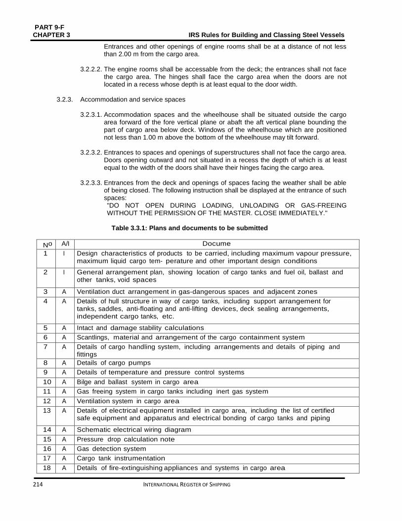
PART 9-F CHAPTER 3 IRS Rules for Building and Classing Steel Vessels
214 INTERNATIONAL REGISTER OF SHIPPING
Entrances and other openings of engine rooms shall be at a distance of not less than 2.00 m from the cargo area.
3.2.2.2. The engine rooms shall be accessable from the deck; the entrances shall not face
the cargo area. The hinges shall face the cargo area when the doors are not located in a recess whose depth is at least equal to the door width.
3.2.3. Accommodation and service spaces
3.2.3.1. Accommodation spaces and the wheelhouse shall be situated outside the cargo area forward of the fore vertical plane or abaft the aft vertical plane bounding the part of cargo area below deck. Windows of the wheelhouse which are positioned not less than 1.00 m above the bottom of the wheelhouse may tilt forward.
3.2.3.2. Entrances to spaces and openings of superstructures shall not face the cargo area.
Doors opening outward and not situated in a recess the depth of which is at least equal to the width of the doors shall have their hinges facing the cargo area.
3.2.3.3. Entrances from the deck and openings of spaces facing the weather shall be able
of being closed. The following instruction shall be displayed at the entrance of such spaces: "DO NOT OPEN DURING LOADING, UNLOADING OR GAS-FREEING WITHOUT THE PERMISSION OF THE MASTER. CLOSE IMMEDIATELY."
Table 3.3.1: Plans and documents to be submitted
No A/I Documents 1 I Design characteristics of products to be carried, including maximum vapour pressure,
maximum liquid cargo tem- perature and other important design conditions
2 I General arrangement plan, showing location of cargo tanks and fuel oil, ballast and other tanks, void spaces
3 A Ventilation duct arrangement in gas-dangerous spaces and adjacent zones
4 A Details of hull structure in way of cargo tanks, including support arrangement for tanks, saddles, anti-floating and anti-lifting devices, deck sealing arrangements, independent cargo tanks, etc.
5 A Intact and damage stability calculations
6 A Scantlings, material and arrangement of the cargo containment system
7 A Details of cargo handling system, including arrangements and details of piping and fittings
8 A Details of cargo pumps
9 A Details of temperature and pressure control systems
10 A Bilge and ballast system in cargo area
11 A Gas freeing system in cargo tanks including inert gas system
12 A Ventilation system in cargo area
13 A Details of electrical equipment installed in cargo area, including the list of certified safe equipment and apparatus and electrical bonding of cargo tanks and piping
14 A Schematic electrical wiring diagram
15 A Pressure drop calculation note
16 A Gas detection system
17 A Cargo tank instrumentation
18 A Details of fire-extinguishing appliances and systems in cargo area

PART 9 – F IRS Rules for Building and Classing Steel Vessels CHAPTER 3
INTERNATIONAL REGISTER OF SHIPPING 215
19 A Arrangement drawing of the various fire bulkheads and decks with standard fire test reports for the various arrange- ments, surface coverings, paints and similar
20 I Loading and unloading operation description, including cargo tank filling limits, where applicable
21 A Gas return system
Note 1:
𝐴 = to be submitted for review/approval in triplicate
𝐼 = to be submitted for information in duplicate
3.2.3.4. Entrances and windows of superstructures and accommodation spaces which can be opened as well as other openings of these spaces shall be positioned not less than 2.00 m from the cargo area. No wheelhouse doors and windows shall be situated within 2.00 m from the cargo area, except where there is no direct association between the wheelhouse and the accommodation.
3.2.3.5. Machinery Arrangement
a) Driving shafts of the bilge or ballast pumps in the cargo area may enter through
the bulkhead between the service space and the engine room, providing the arrangement of the service space is in compliance with [3.2.4.6].
b) The Society shall approve the penetration of the shaft through the bulkhead which shall be gastight.
c) The necessary operating instructions shall be displayed.
d) Penetrations through the bulkhead between the engine room and the service space in the cargo area, and the bulkhead between the engine room and the hold spaces may be provided for electrical cables, hydraulic and piping for measuring, control and alarm systems, on condition that the penetrations have been permitted by the Society. The penetrations shall be gastight. Penetrations through a bulkhead with “A-60” fire protection insulation, shall have an equivalent fire protection.
e) Pipes may enter the bulkhead between the engine room and the service space in the cargo area provided that these are pipes between the mechanical equipment in the engine room and the service space which do not have any openings within the service space and which are provided with shut-off devices at the bulkhead in the engine room.
f) Nevertheless [3.2.4.4], pipes from the engine room may penetrate the service space in the cargo area or a cofferdam or a hold space or a double-hull space to the outside provided that within the service space or cofferdam or hold space or doublehull space they are of the thick-walled type and have no flanges or openings.
g) Where a driving shaft of auxiliary machinery penetrates through a wall located above the deck the penetration shall be gastight.
3.2.3.6. A service space located within the cargo area below deck shall not be used as a
cargo pump room for the loading and unloading system, except where:

PART 9-F CHAPTER 3 IRS Rules for Building and Classing Steel Vessels
216 INTERNATIONAL REGISTER OF SHIPPING
the pump room is separated from the engine room or from service spaces outside the cargo area by a cofferdam or a bulkhead with an “A-60” fire protection insulation, or by a service space or a hold space
The “A-60” bulkhead required above does not contain penetrations referred to in [3.2.3.5] (a)
Ventilation exhaust outlets are located not less than 6.00 m from entrances and openings of the accommodation and service spaces outside the cargo area
The access hatches and ventilation inlets can be closed from the outside
All pipes for loading and unloading as well as those of stripping systems are provided with shut-off devices at the pump suction side in the cargo pump room immediately at the bulkhead. The necessary operation of the control devices in the pump room, starting of pumps and necessary control of the liquid flow rate shall be effected from the deck
The bilge of the cargo pump room is fitted out with a gauging device for measuring the filling level which activates a visual and audible alarm in the wheelhouse when a liquid is storing in the cargo pump room bilge
The cargo pump room is provided with a permanent gas detection system which automatically directs the presence of explosive gases or lack of oxygen by means of direct-measuring sensors and which actuates a visual and audible alarm when the gas concentration has reached 20% of the lower explosive limit. The sensors of this system shall be placed at suitable positions at the bottom and directly below the deck.
Measurement shall be continuous.
The audible and visual alarms are connected in the wheelhouse and in the cargo pump room and, when the alarm is actuated; the loading and unloading system is shut down. Failure of the gas detection system shall be immediately signalled in the wheelhouse and on deck by means of audible and visual alarms
The ventilation system prescribed in [3.2.5.3] has a capacity of not less than 30 changes of air per hour based on the total volume of the service space.
3.2.3.7. The following instruction shall be displayed at the entrance of the cargo pump
room: BEFORE ENTERING THE CARGO PUMP-ROOM CHECK WHETHER IT IS FREE FROM GASES AND CONTAINS SUFFICIENT OXYGEN. DO NOT OPEN DOORS AND ENTRANCE OPENINGS WITHOUT THE PERMISSION OF THE MASTER. LEAVE IMMEDIATELY IN EVENT OF ALARM.
3.2.4. Hold spaces
3.2.4.1. The cargo tanks shall be separated by cofferdams of at least 0.60 m in width from the accommodation, engine room and service spaces outside the cargo area below deck or, if there are no such accommodation, engine room and service spaces, from the vessel’s ends. A space of not less than 0.50 m shall be provided between

PART 9 – F IRS Rules for Building and Classing Steel Vessels CHAPTER 3
INTERNATIONAL REGISTER OF SHIPPING 217
such tanks and the end bulkheads of the hold space when the cargo tanks are installed in a hold space. In this case an end bulkhead meeting at least the definition for Class “A-60”, shall be considered equivalent to a cofferdam. For pressure cargo tanks, the 0.50 m distance may be reduced to 0.20 m.
3.2.4.2. Hold spaces, cofferdams and cargo tanks shall have arrangement for survey and
checking.
3.2.4.3. All spaces in the cargo area shall be well ventilated. Means for checking their gas-free condition shall be provided.
3.2.4.4. The bulkheads bounding the cargo tanks, cofferdams and hold spaces shall be
watertight. The cargo tanks and the bulkheads bounding the cargo area shall have no openings or penetrations below deck. The bulkhead between the engine room and the cofferdam or service space in the cargo area or between the engine room and a hold space may be fitted with penetrations provided that they conform to the provisions of [2.3.5].
The bulkhead between the cargo tank and the cargo pump room below deck may be fitted with penetrations provided that they follow to the provisions of [3.2.3.6]. The bulkheads between the cargo tanks may be fitted with penetrations on condition that the loading or unloading pipes are fixed with shut-off devices in the cargo tank. The shut-off devices shall be operable from the deck.
3.2.4.5. Double hull spaces and double bottoms in the cargo area shall be prepared for
being filled with ballast water only. Double bottoms may, however, be used as fuel oil tanks, provided they comply with [3.2.7].
3.2.4.6.
a) A cofferdam, the centre part of a cofferdam or another space below deck in the cargo area may be prepared as a service space, on condition that the bulkheads bounding the service space spread out vertically to the bottom. This service space shall only be accessible from the deck.
b) The service space shall be watertight with the exception of its access hatches and ventilation inlets.
c) No pipes for loading and unloading shall be fitted within the service space referred to under (a) above. Pipes for loading and unloading may be fitted in the cargo pump-rooms below deck only when they conform to the provisions of [3.2.3.6].
3.2.4.7. The service spaces shall be arranged so as to be easily accessible and to permit
persons wearing protective clothing and breathing apparatus to safely operate the service equipment contained therein where service spaces are positioned in the cargo area under deck. They shall be planned so as to allow injured or unconscious personnel to be removed from such spaces without difficulty, if necessary by means of fixed equipment.
3.2.4.8. Cofferdams, double-hull spaces, double bottoms, cargo tanks, hold spaces and
other accessible spaces within the cargo area shall be planned so that they may be completely checked and cleaned in a proper way. The dimensions of openings except for those of double-hull spaces and double bottoms which do not have a wall adjoining the cargo tanks shall be sufficient to allow a person wearing breathing apparatus to enter or leave the space without difficulties. These openings shall have a minimum cross-sectional area of 0.36 m2 and a minimum side length of 0.50 m. They shall be designed so as to allow an injured or unconscious person

PART 9-F CHAPTER 3 IRS Rules for Building and Classing Steel Vessels
218 INTERNATIONAL REGISTER OF SHIPPING
to be removed from the bottom of such a space without difficulties, if necessary by means of fixed equipment. In these spaces the distance between the reinforcements shall not be less than 0.50 m. In double bottoms this distance may be reduced to 0.45 m.
3.2.4.9. Cargo tanks may have circular openings with a diameter of not less than 0.68 m.
3.2.5. Ventilation
3.2.5.1. Each hold space shall have two openings the dimensions and location of which shall be such as to allow effective ventilation of any part of the hold space. If there are no such openings, it shall be possible to fill the hold spaces with inert gas or dry air.
3.2.5.2. Double-hull spaces and double bottoms within the cargo area which are not
arranged for being filled with ballast water, hold spaces and cofferdams shall be arranged for ventilation systems.
3.2.5.3. Any service spaces located in the cargo area below deck shall be provided with a
system of forced ventilation with sufficient power for confirming at least 20 changes of air per hour based on the volume of the space. The ventilation exhaust ducts shall extend down to 50 mm above the bottom of the service space. The air shall be passed through a duct at the top of the service space. The air inlets shall be placed not less than 2.00 m above the deck, at a distance of not less than 2.00 m from tank openings and 6.00 m from the outlets of safety valves. The extension pipes, which may be necessary, may be of the hinged type.
3.2.5.4. Ventilation of accommodation and service spaces shall be possible. 3.2.5.5. Ventilators used in the cargo area shall be designed so that no sparks may be
released on contact of the impeller blades with the housing and no static electricity may be produced.
3.2.5.6. Notice boards shall be fixed at the ventilation inlets indicating the conditions when
they shall be closed. All ventilation inlets of lodging space and service spaces leading outside shall be fixed with fire flaps. Such ventilation inlets shall be placed not less than 2.00 m from the cargo area.
Ventilation inlets of service spaces in the cargo area may be placed within such area.
3.2.5.7. The flame-arresters prescribed in [3.2.11.4], [3.3.7.4] and [3.3.7.5] shall be of a
type approved for this purpose by the Society.
3.2.6. Engines
3.2.6.1. Only internal combustion engines running on fuel with a flashpoint of more than 55 °C are allowed.
3.2.6.2. Ventilation inlets of the engine room and, when the engines do not take in air
straight from the engine room, the air intakes of the engines shall be placed not less than 2.00 m from the cargo area.
3.2.6.3. Sparking shall not be possible within the cargo area.
3.2.6.4. The surface temperature of the outer parts of engines used during loading or
unloading operations, as well as that of their air inlets and exhaust ducts shall not
PART 9 – F IRS Rules for Building and Classing Steel Vessels CHAPTER 3
INTERNATIONAL REGISTER OF SHIPPING 219
go beyond the allowable temperature according to the temperature class of the substances carried. This provision does not apply to engines installed in service spaces on condition that the provisions of [3.8.3.2] are fully complied with.
3.2.6.5. The ventilation in the closed engine room shall be projected so that, at an ambient
temperature of 20°C, the average temperature in the engine room does not go beyond 40°C.
3.2.7. Oil fuel tanks
3.2.7.1. The double bottoms within these spaces may be arranged as oil fuel tanks, provided their depth is not less than 0.60 m when the vessel is provided with hold spaces. Oil fuel pipes and openings of such tanks are not allowed in the hold space.
3.2.7.2. The open ends of the air pipes of all oil fuel tanks shall outspread to not less than
0.50 m above the open deck. Their open ends and the open ends of overflow pipes leading on the deck shall be fixed with a protective device containing of a gauze diaphragm or a punctured plate.
3.2.8. Exhaust pipes
3.2.8.1. Exhausts shall be expatriated from the vessel into the open air either upwards through an exhaust pipe or through the shell plating. The exhaust outlet shall be located not less than 2.00 m from the cargo area. The exhaust pipes of engines shall be prepared so that the exhausts are led away from the vessel. The exhaust pipes shall not be placed within the cargo area.
3.2.8.2. Exhaust pipes shall be provided with a device preventing the escape of sparks, e.g.
spark arresters.
3.2.9. Bilge pumping and ballasting arrangements 3.2.9.1. Bilge and ballast pumps for spaces within the cargo area shall be installed within
such area. This provision does not apply to:
Double hull spaces and double bottoms which do not have a common boundary wall with the cargo tanks;
Cofferdams, double hull spaces, hold spaces and double bottoms where ballasting is performed using the piping of the firefighting system in the cargo area and bilge pumping is performed using eductors.
3.2.9.2. Double bottom shall not be connected to the bilge piping system, where it is used
as oil fuel tank. 3.2.9.3. The standpipe and its outboard connection for suction of ballast water shall be
located within the cargo area but outside the cargo tanks, where the ballast pump is installed in the cargo area.
3.2.9.4. A cargo pump room below deck shall be capable of being drained in an emergency by an installation located in the cargo area and independent from any other installation. This installation shall be done outside the cargo pump room.
3.2.10. Ventilation of cargo pump rooms
3.2.10.1. Cargo pump rooms must be equipped with extraction type ventilation systems,
independent of other vessel's spaces, providing at least 30 cycles of air change per

PART 9-F CHAPTER 3 IRS Rules for Building and Classing Steel Vessels
220 INTERNATIONAL REGISTER OF SHIPPING
hour. Warning notices shall be placed needing that the ventilation is in operation for at least 15 minutes prior to entering these spaces.
3.2.10.2. Portable means must be provided for gas-freeing of cargo tanks and other spaces
not equipped with fixed ventilation.
3.2.11. Arrangements of cofferdams
3.2.11.1. Cofferdams or cofferdam compartments remaining once a service space has been set in accordance with [3.2.4.6] shall be accessible through an access hatch. If, on the other hand, the cofferdam is connected to a double-hull space, it is sufficient for it to be accessible from that space.
3.2.11.2. Cofferdams shall be capable of being filled with water and emptied by means of a
pump. Filling shall be made within 30 minutes. These requirements are not applicable when the bulkhead between the engine room and the cofferdam comprises fire-protection insulation “A-60” or has been fitted out as a service space. The cofferdams shall not be fixed with inlet valves.
3.2.11.3. No fixed pipe shall permit connection between a cofferdam and other piping of the
vessel outside the cargo area.
3.2.11.4. The ventilation openings of cofferdams shall be fixed with a flame-arrester enduring a deflagration.
3.3. Cargo containment
3.3.1. General The scantlings and structural arrangements are to be in compliance with applicable requirements of Chapter 1, Sec 3, [3.4] to 3.7.
3.3.2. Cargo area hull design
3.3.2.1. In the cargo area with the exception of the cofferdams, the vessel shall be
designed as a flush-deck double-hull tanker, i.e. with double hull spaces and double bottoms but without trunk.
3.3.2.2. Cargo tanks independent of the vessel’s hull and refrigerated cargo tanks may only
be installed in a hold space which is bounded by double hull spaces and double bottoms in accordance with [3.3.2.5]. The cargo tanks shall not extend beyond the deck.
3.3.2.3. Side-stringers joining or supporting the load-bearing components of the sides of the
vessel with the load-bearing components of the longitudinal walls of cargo tanks and side-stringers linking the load-bearing components of the vessel’s bottom with the tank-bottom are prohibited.
3.3.2.4. A local recess in the cargo deck, contained on all sides, with a depth greater than
0.1 m, designed to house the loading and unloading pump, is permitted if it fulfills the following conditions:
The recess shall not be greater than 1 m in depth
The recess shall be located not less than 6 m from entrances to and openings of accommodation and service spaces outside the cargo area
PART 9 – F IRS Rules for Building and Classing Steel Vessels CHAPTER 3
INTERNATIONAL REGISTER OF SHIPPING 221
The recess shall be located at a minimum distance from the side plating equal to one quarter of the vessel’s breadth
All pipes linking the recess to the cargo tanks shall be fitted with shut-off devices fitted directly on the bulkhead
All the controls required for the equipment located in the recess shall be activated from the deck
If the recess is deeper than 0.5 m, it shall be provided with a permanent gas detection system which automatically indicates the presence of explosive gases by means of direct-measuring sensors and actuates a visual and audible alarm when the gas concentration has reached 20% of the lower explosion limit. The sensors of this system shall be placed at suitable positions at the bottom of the recess. Measurement shall be continuous
Visual and audible alarms shall be installed in the wheelhouse and on deck and, when the alarm is actuated, the vessel loading and unloading system shall be shut down. Failure of the gas detection system shall be immediately signalled in the wheelhouse and on deck by means of visual and audible alarms
It shall be possible to drain the recess using a system installed on deck in the cargo area and independent of any other system
The recess shall be provided with a level alarm device which activates the draining system and triggers a visual and audible alarm in the wheelhouse when liquid accumulates at the bottom
When the recess is located above the cofferdam, the engine room bulkhead shall have an ‘A-60’ fire protection insulation
When the cargo area is fitted with a water-spray system, electrical equipment located in the recess shall be protected against infiltration of water
Pipes connecting the recess to the hull shall not pass through the cargo tanks.
3.3.2.5. For double hull construction with the cargo tanks integrated in the vessel’s
structure, the distance between the side wall and the inner side wall of the vessel shall be not less than 1.00 m. A distance of 0.80 m may however be permitted, provided that, compared with the scantling requirements specified in Chapter 1, Sec 3, [3.4], the following reinforcements have been made:
a) 25% increase in the thickness of the deck stringer plate b) 15% increase in the side plating thickness c) Arrangement of a longitudinal framing system at the vessel’s side, where
depth of the longitudinals shall be not less than 0.15 m and the longitudinals shall have a face plate with the cross sectional area of at least 7.0 cm2
d) The stringer or longitudinal framing systems shall be maintained by web frames, and like bottom girders fitted with lightening holes, at a maximum spacing of 1.80 m. These distances may be increased if the longitudinal are strengthened consequently.

PART 9-F CHAPTER 3 IRS Rules for Building and Classing Steel Vessels
222 INTERNATIONAL REGISTER OF SHIPPING
3.3.2.6. A longitudinal stringer system shall be fitted instead of [3.3.2.5] c) when the vessel is built according to the transverse framing system. The spacing of the longitudinal stringers shall not be greater than 0, 80 m and the stringer depth shall not be less than 0, 15 m, with full connection to the frames. As in [3.3.2.5] c), the cross sectional area of the flange or face plate shall not be less than 7, 0 cm2. The web depth of the stringer shall be increased by the depth of cutouts where cutouts are arranged in the stringer at the connection with the frames.
3.3.2.7. The mean depth of the double bottoms shall be not less than 0.70 m. It shall,
however, never be less than 0.60 m. 3.3.2.8. The depth of the double bottom below the suction wells may be reduced to 0.5 m. 3.3.2.9. Alternative construction fulfilling Chapter 3, ******* are permitted.
3.3.2.10. The distance between the double walls of the hold space shall not be less than 0.80 m and the depth of the double bottom shall not be less than 0.60 m, when a vessel is built with cargo tanks located in the hold space or refrigerated cargo tanks.
3.3.3. Cargo tank sizes
3.3.3.1. In accordance with Table 3.3.2, the maximum allowable capacity of a cargo tank
for single hull tank vessels, double hull tank vessels and vessels with tanks independent of the hull shall be determined
where: LOAB D: Product of the tank vessel main dimensions, in m3
LOA ∶ overall length of the hull, in m In the case of trunk deck vessels, D’ is to be
substituted for D. D’ is to be determined by the following formula:
D'= D + h
btlt
𝐵𝐿𝑂𝐴
where: ht: Height, in m, of trunk (distance between trunk deck and main deck on trunk side measured at LOA/2)
bt: Trunk breadth, in ml
lt: Trunk length, in m
3.3.3.2. Alternative constructions in compliance with Chapter 3, are permitted.
Table 3.3.2: Tank sizes
𝑳𝑶𝑨 𝑩 𝑫, in m3 Maximum permissible capacity of a cargo tank, in m³
< 600 0,3 𝐿𝑂𝐴 𝐵 𝐷
from 600 to 3750 180 + (𝐿𝑂𝐴 𝐵 𝐷 − 600) 0,0635
> 3750 380
3.3.4. Cargo tank arrangements
3.3.4.1. The cargo tank is to fulfill the following:
For vessels with a length not more than 50.00 m, the length of a cargo tank shall not exceed 10.00 m

PART 9 – F IRS Rules for Building and Classing Steel Vessels CHAPTER 3
INTERNATIONAL REGISTER OF SHIPPING 223
For vessels with a length of more than 50.00 m, the length of a cargo tank shall not exceed 0.20 L, where L is the vessel rule length. This provision does not apply to vessels with independent built-in cylindrical tanks having a length to diameter ratio ≤ 7.
3.3.4.2. The volume of a suction well shall be restricted to not more than 0.10 m3
3.3.5. Integrated tank scantlings
The scantlings of the integrated tank structure are to be determined in compliance with Chapter 1, Sec 3, [3.4].
3.3.6. Independent cargo tank scantlings
3.3.6.1. Tank scantlings The scantlings of the independent tank structure are to be determined in compliance with Chapter 1, Sec 3, [3.4.1.3]. These tanks shall be designed in compliance with Part D, Chapter 3 when the vessel is provided with pressure cargo tanks for a working pressure of 400 kPa.
3.3.6.2. Supports and fastenings
The cargo tanks independent of the vessel’s hull shall be fixed in such way that they cannot float.
3.3.7. Cargo tank openings
a) Cargo tank openings shall be located on deck in the cargo area.
b) Cargo tank openings with a cross-section of more than 0.10 m2 and openings of safety devices for preventing overpressures shall be placed not less than 0.50 m above deck.
3.3.7.1. In accordance with Part 9C, Chapter 2, Sec 8, cargo tank openings shall be fixed
with gastight closures capable of withstanding the test pressure. 3.3.7.2. Closures which are normally used during loading or unloading operations shall not
cause sparking when functioned. 3.3.7.3. Safety devices
Each cargo tank or group of cargo tanks linked to a common vapour pipe shall be fixed with:
Safety devices for preventing objectionable overpressures or vacuums. When anti-explosion protection is needed, the vacuum valve shall be fixed with a flame arrester capable of enduring a deflagration and the pressure-relief valve with a high-velocity vent valve capable of enduring steady burning. The gases shall be discharged upwards. The opening pressure of the high-velocity vent valve and the opening pressure of the vacuum valve shall be permanently indicated on the valves
A connection for the safe return ashore of gases expelled during loading
A device for the safe depressurisation of the tanks consisting of at least a fire-resistant flame-arrester and a stop valve which clearly indicates whether it is open or shut.

PART 9-F CHAPTER 3 IRS Rules for Building and Classing Steel Vessels
224 INTERNATIONAL REGISTER OF SHIPPING
3.3.7.4. Arrangement for safety devices
The outlets of high-velocity vent valves shall be located not less than 2.00 m above the deck and at a distance of not less than 6.00 m from the lodging space and from the service spaces outside the cargo area. This height may be reduced when within a radius of 1.00 m round the outlet of the high velocity vent valve, there is no equipment, no work is being performed and signs indicate the area. The setting of the high-velocity vent valves shall be such that during the transport operation they do not blow off until the maximum permissible working pressure of the cargo tanks is reached.
3.3.7.5. Anti-explosion protection
a) Insofar as anti-explosion protection is recommended, a vapour pipe joining two or more cargo tanks shall be fixed, at the connection to each cargo tank, with a flame arrester with a fixed or spring-loaded plate stack, capable of enduring a detonation. This equipment may consist of:
A flame arrester fitted with a fixed plate stack, where each cargo tank is fixed with a vacuum valve capable of enduring a deflagration and a high-velocity vent valve capable of withstanding steady burning
A flame arrester fitted with a spring-loaded plate stack, where each cargo tank is fitted with a vacuum valve capable of withstanding a deflagration
A flame arrester with a fixed plate stack
A flame arrester with a fixed plate stack, where the pressure-measuring device is fitted with an alarm system in accordance with [3.10.5] A flame arrester with a spring-loaded plate stack, where the pressure-measuring device is fitted with an alarm system in accordance with [3.10.5].
Flame arresters need not be required for individual cargo tanks when a fire-fighting installation is permanently mounted on deck in the cargo area and can be brought into service from the deck and from the wheelhouse. Only substances which do not mix and which do not react dangerously with each other may be carried at the same time in cargo tanks connected to a common vapour pipe.
or b) A vapour pipe connecting two or more cargo tanks shall be fitted insofar as
anti-explosion protection is prescribed, at the connection to each cargo tank, with a pressure/vacuum relief valve incorporating a flame arrester capable of withstanding a detonation/deflagration. Only substances which do not mix and which do not react dangerously with each other may be carried at the same time in cargo tanks connected to a common vapour pipe.
or c) Insofar as anti-explosion protection is recommended, an independent vapour
pipe for each cargo tank, fixed with a vacuum valve integrating a flame arrester capable of withstanding a deflagration and a high velocity vent valve incorporating a flame arrester capable of withstanding steady burning. Numerous different substances may be carried at the same time.
or d) Insofar as anti-explosion protection is prescribed, a vapour pipe connecting
two or more cargo tanks shall be fitted, at the connection to each cargo tank, with a shut-off device capable of withstanding a detonation, where each cargo tank is fitted with a vacuum valve capable of enduring a deflagration and a high velocity vent valve capable of enduring steady burning.

PART 9 – F IRS Rules for Building and Classing Steel Vessels CHAPTER 3
INTERNATIONAL REGISTER OF SHIPPING 225
Only substances which do not mix and which do not react dangerously with each other may be carried at the same time in cargo tanks connected to a common vapour pipe.
3.4. Cargo piping system
3.4.1. General
Pumps, compressors and accessory loading and unloading piping shall be placed in the cargo area. Cargo pumps shall be capable of being shut down from the cargo area and, additionally, from a position outside the cargo area. Cargo pumps located on deck shall be located not less than 6.00 m from entrances to or openings of the lodging space and service spaces outside the cargo area.
3.4.2. Arrangement of cargo piping 3.4.2.1. Pipes for loading and unloading shall be independent of any other piping of the
vessel. No cargo piping shall be located below deck, except for those inside the cargo tanks and inside the cargo pump room.
3.4.2.2. The pipes for loading and unloading shall be arranged so that, after loading or
unloading operations, the liquid remaining in these pipes may be safely removed and may flow either into the vessel’s tanks or the tanks ashore.
3.4.2.3. Piping for loading and unloading shall be clearly distinguishable from other piping,
e.g. by means of colour marking. 3.4.2.4. The pipes for loading and unloading located on deck, with the exception of the
shore connections shall be located not less than 𝐵/4 from the outer shell. 3.4.2.5. The shore connections shall be located not less than 6.00 m from the entrances to
or openings of, the accommodation and service spaces outside the cargo area. 3.4.2.6. Each shore connection of the vapour pipe and shore connections of the pipes for
loading and unloading, through which the loading or unloading operation is carried out, shall be fitted with a shut-off device. However, each shore connection shall be fitted with a blind flange when it is not in operation.
3.4.2.7. The flanges and stuffing boxes shall be provided with a spray protection device. 3.4.2.8. Pipes for loading and unloading, and vapour pipes, shall not have flexible
connections fitted with sliding seals. 3.4.2.9. Filling pipes for cargo tanks are to extend down as close as possible to the bottom
of the tank.
3.4.2.10. The distance referred to in [3.4.1.1] and [3.4.2.5] may be reduced to 3.00 m if a transverse bulkhead complying with [3.2.1.2] is situated at the end of the cargo area. The openings shall be provided with doors. The following notice shall be displayed on the doors:
DO NOT OPEN DURING LOADING AND UNLOADING WITHOUT THE PERMISSION OF THE MASTER.CLOSE IMMEDIATELY.
3.4.2.11. If the vessel is carrying several dangerous substances liable to react dangerously
with each other, a separate pump with its own piping for loading and unloading shall be installed for each substance. The piping shall not cross a cargo tank
PART 9-F CHAPTER 3 IRS Rules for Building and Classing Steel Vessels
226 INTERNATIONAL REGISTER OF SHIPPING
containing dangerous substances with which the substance in question is liable to react.
3.4.3. Control, monitoring and alarm devices
3.4.3.1. Stop valves
The stop valves or other shut-off devices of the pipes for loading and unloading shall show whether they are open or shut.
3.4.3.2. Pressure gauges
The pipes for loading and unloading shall be fixed with pressure gauges at the outlet of the pumps. The allowable maximum overpressure or vacuum value shall be specified on each measuring device. Readings shall be possible in all weather conditions.
3.4.4. Bonding
Every component of the pipes for loading and unloading shall be electrically joined to the hull.
3.4.5. Supply of cargo tanks with washing or ballast water
3.4.5.1. The suctions of these pipes shall be positioned within the cargo area but outside
the cargo tanks when pipes for loading and unloading are used for supplying the cargo tanks with washing or ballast water. Pumps for tank washing systems with related connections may be located outside the cargo area, provided the discharge side of the system is arranged in such a way that suction is not possible through that part. A spring-loaded non-return valve shall be attached to prevent any gases from being expelled from the cargo area through the tank washing system.
3.4.5.2. A non-return valve shall be fixed at the junction between the water suction pipe and
the cargo loading pipe.
3.4.6. Permissible loading and unloading flows
3.4.6.1. The permissible loading and unloading flows shall be calculated. 3.4.6.2. Taking into account the design of the ventilation system calculations concern the
permissible maximum loading and unloading flow for each cargo tank or each group of cargo tanks,. These calculations shall take into consideration the fact that in the event of an unexpected cut-off of the gas return piping or the compensation piping of the shore facility, the safety devices of the cargo tanks will stop pressure in the cargo tanks from exceeding the following values:
over-pressure: 115% of the opening pressure of the high-velocity vent valve;
vacuum pressure: not more than the construction vacuum pressure but not exceeding 5 kPa
3.5. Cargo pressure and temperature control
3.5.1. Cargo tank heating
3.5.1.1. Cargo tank heating system is to be fitted as a separate system, equipped with a heat exchanger located in the cargo area. Where special heat transfer media are used this requirement may be dispensed with upon approval by the Society.

PART 9 – F IRS Rules for Building and Classing Steel Vessels CHAPTER 3
INTERNATIONAL REGISTER OF SHIPPING 227
3.5.1.2. Boilers which are used for heating the cargo shall be fuelled with a liquid fuel having a flashpoint of more than 55°C. They shall be located either in the engine room or in another separate space below deck and outside the cargo area, which is accessible from the deck or from the engine room.
3.5.1.3. The cargo heating system shall be planned so that the cargo cannot penetrate into
the boiler in the case of a leak in the heating coils. A cargo heating system with artificial draught shall be burned electrically.
3.5.1.4. The ventilation system of the engine room shall be designed taking into account
the air required for the boiler. 3.5.1.5. The service space which contains this system shall fully comply with the
requirements of [3.8.3.1] b) where the cargo heating system is used during loading, unloading or gas-freeing. These necessities do not apply to the inlets of the ventilation system. These inlets shall be positioned at a minimum distance of 2.00 m from the cargo area and 6.00 m from the openings of cargo tanks or residual cargo tanks, loading pumps positioned on deck, openings of high velocity vent valves, pressure relief devices and shore connections of loading and unloading pipes and must be located not less than 2.00 m above the deck.
The requirements of [3.8.3.1] b) are not applicable to the unloading of substances having a flash point of 60°C or more when the temperature of the product is at least 15 K lower at the flash point.
3.5.2. Water spray system
3.5.2.1. When water spraying is required in column (9) of Table C of ADN Chapter 3.2, a
water spray system shall be fitted in the cargo area on deck to enable gas emissions from loading to be precipitated and to cool the tops of cargo tanks by spraying water over the whole surface so as to avoid safely the activation of the high-velocity vent at 50 kPa.
3.5.2.2. The gas precipitation system shall be fixed with a connection device for supply
from a shore installation. 3.5.2.3. The spray nozzles shall be so installed that the entire cargo deck area is covered
and the gases released are triggered safely. 3.5.2.4. The system shall be capable of being put into operation from the wheelhouse and
from the deck. Its capability shall be such that when all the spray nozzles are in operation, the outflow is not less than 50 litres per square metre of deck area and per hour.
3.6. Tanks and receptacles for residual products and receptacles for slops
3.6.1. General
3.6.1.1. If vessels are provided with a tank for residual products, it shall fulfill the provisions of [3.6.1.3] to [3.6.1.7].
Receptacles for residual products and receptacles for slops shall be positioned only in the cargo area. During the filling of the receptacles for residual products, means for collecting any leakage shall be placed under the filling connections.
3.6.1.2. Receptacles for slops shall be fire resistant and shall be capable of being closed
with lids. The receptacles for slops shall be marked and be easy to handle.

PART 9-F CHAPTER 3 IRS Rules for Building and Classing Steel Vessels
228 INTERNATIONAL REGISTER OF SHIPPING
3.6.1.3. The maximum capacity of a tank for residual products is 30 m3 3.6.1.4. The tank for residual products shall be equipped with:
pressure-relief and a vacuum relief valves.
The high velocity vent valve shall be so controlled as not to open during carriage. This condition is met when the opening pressure of the valve meets the conditions set out in column (10) of Table C of ADN Regulations Chapter 3.2. The vacuum-relief valve shall be capable of enduring deflagrations and the high velocity vent valve shall endure steady burning, when anti-explosion protection is required in column (17) of Table C of ADN Regulations Chapter 3.2.
a level indicator
connections with shut-off devices, for pipes and hoses.
3.6.1.5. Receptacles for residual products shall be equipped with:
a connection enabling gases released during filling to be evacuated safely
A possibility of indicating the degree of filling
Connections with shut-off devices, for pipes and hoses.
3.6.1.6. Receptacles for residual products shall be linked to the vapour pipe of cargo tanks only for the time necessary to fill them.
3.6.1.7. Receptacles for residual products and receptacles for slops positioned on the deck
shall be located at a minimum distance from the hull equal to one quarter of the vessel’s breadth.
3.7. Environmental control
3.7.1. Inerting facility
3.7.1.1. In cases in which inerting or blanketing of the cargo is prescribed, the vessel shall
be prepared with an inerting system. 3.7.1.2. This system shall be capable of maintaining a permanent minimum pressure of 7
kPa (0.07 bar) in the spaces to be inerted. Additionally, the inerting system shall not increase the pressure in the cargo tank to a pressure greater than that at which the pressure valve is regulated. The set pressure of the vacuum-relief valve shall be 3.5 kPa (0.035 bar).
3.7.1.3. An adequate quantity of inert gas for loading or unloading shall be carried or
produced on board if it is not possible to get it on shore. Additionally, a sufficient quantity of inert gas to offset normal losses going on during carriage shall be on board.
3.7.1.4. The premises to be inerted shall be equipped with connections for introducing the
inert gas and monitoring systems so as to ensure the correct atmosphere on a permanent basis.
3.7.1.5. This monitoring system shall initiate an audible and visible alarm in the
wheelhouse, when the pressure or the concentration of inert gas in the gaseous phase falls below a given value. When the wheelhouse is vacant, the alarm shall also be perceptible in a location occupied by a crew member.

PART 9 – F IRS Rules for Building and Classing Steel Vessels CHAPTER 3
INTERNATIONAL REGISTER OF SHIPPING 229
3.8. Electrical installations 3.8.1. Documents to be kept on board
3.8.1.1. Moreover to the documents required in Part E, Chapter 1 , Sec 1, [1.2] and Sec 4, the following documents shall be on board:
a) a drawing indicating the boundaries of the cargo area and the location of the electrical equipment installed in this area
b) a list of the electrical equipment referred to in (a) above including the following particulars: machine or appliance, location, type of protection, type of protection
c) against explosion, testing body and approval number d) a list of or general plan indicating the electrical equipment outside the cargo
area which may be operated during loading, unloading or gas-freeing. All other electrical equipment shall be marked in red.
3.8.2. General design requirements
3.8.2.1. Only distribution systems without return connection to the hull are allowable. This provision does not apply to:
Certain limited sections of the installations situated outside the cargo area (connections of starters of diesel engines)
Device for checking the insulation level referred to in [3.8.2.2]
Active cathodic corrosion protection.
3.8.2.2. Every insulated distribution network shall be fixed with an automatic device with a visual and audible alarm for checking the insulation level.
3.8.2.3. The explosion groups and temperature classes assigned to the substances carried
shall be taken into consideration, for the selection of electrical equipment to be used in zones presenting an explosion risk.
3.8.3. Type and location of electrical equipment
3.8.3.1. a) Only measuring, regulation and alarm devices of the EEx (ia) type of protection
may be installed in cargo tanks, residual cargo tanks and pipes for loading and unloading (comparable to zone 0)
b) Only the following equipment may be set up in the cofferdams, double-hull
spaces, double bottoms and hold spaces (comparable to zone 1):
Measuring, regulation and alarm devices of the certified safe type
Lighting appliances of the "flame-proof enclosure" or "pressurised enclosure" type of protection
Hermetically sealed echo sounding devices the cables of which are led through thick-walled steel tubes with gastight connections up to the main deck
Cables for the active cathodic protection of the shell plating in protective steel tubes such as those provided for echo sounding devices
c) Only the following equipment may be set up in the service spaces in the cargo
area below deck (comparable to zone 1):
Measuring, regulation and alarm devices of the certified safe type

PART 9-F CHAPTER 3 IRS Rules for Building and Classing Steel Vessels
230 INTERNATIONAL REGISTER OF SHIPPING
Lighting appliances of the "flame-proof enclosure" or "apparatus protected by pressurization" type of protection
Motors driving essential equipment such as ballast pumps; they shall be of the certified safe type
d) The control and protective equipment of the electrical equipment referred to in paragraphs (a), (b) and (c) above shall be positioned outside the cargo area if they are not essentially safe.
e) The electrical equipment in the cargo area on deck (comparable to zone 1) shall
be of the certified safe type.
3.8.3.2.
a) Electrical equipment used during loading, unloading and gas-freeing during berthing and which are located outside the cargo area shall (comparable to zone 2) be at least of the "limited explosion risk" type.
b) This provision does not apply to:
Lighting installations in the accommodation, except for switches near entrances to accommodation
Radiotelephone installations in the accommodation or the wheelhouse
Mobile and fixed telephone installations in the accommodation or the wheelhouse
Electrical installations in the accommodation, the wheelhouse or the service spaces outside the cargo areas if:
These spaces are fixed with a ventilation system confirming an overpressure of 0.1 kPa (0.001 bar) and none of the windows is capable of being opened; the air intakes of the ventilation system shall be located as far away as possible, however, not less than 6.00 m from the cargo area and not less than 2.00 m above the deck
The spaces are fixed with a gas detection system with sensors: - At the suction inlets of the ventilation system - Directly at the top edge of the sill of the entrance doors of the
accommodation and service spaces
The gas concentration measurement is continuous
The ventilators are switched off, when the gas concentration reaches 20% of the lower explosive limit. In such a case and when the overpressure is not sustained or in the event of failure of the gas detection system, the electrical installations which do not fulfill (a) above, shall be switched off. These operations shall be carried out immediately and automatically and activate the emergency lighting in the accommodation, the wheelhouse and the service spaces, which shall fulfill at least with the "limited explosion risk" type. The switching-off shall be directed in the accommodation and wheelhouse by visual and audible signals
The ventilation system, the gas detection system and the alarm of the switch-off device fully comply with the requirements of (a) above
The automatic switching-off device is arranged in such manner so that no automatic switch off may occur while the vessel is under way.
3.8.3.3. The electrical equipment which does not meet the requirements set out in [3.8.3.2]
together with its switches shall be marked in red. The discontinuation of such equipment shall be functioned from a centralised location on board.

PART 9 – F IRS Rules for Building and Classing Steel Vessels CHAPTER 3
INTERNATIONAL REGISTER OF SHIPPING 231
3.8.3.4. A permanent electric engine generator which does not meet the requirements of [3.8.3.2] shall be fixed with a switch capable of shutting down the excitation of the generator. A notice board with the operating instructions shall be shown near the switch.
3.8.3.5. Sockets for the connection of signal lights and gangway lighting shall be
permanently fixed to the vessel close to the signal mast or the gangway. Connecting and disconnecting shall not be possible except when the sockets are not live.
3.8.3.6. The failure of the power supply for the safety and control equipment shall be
instantly specified by visual and audible signals at the locations where the alarms are usually actuated.
3.8.4. Earthing
3.8.4.1. The metal parts of electrical appliances in the cargo area which are not live as well
as protective metal tubes or metal sheaths of cables in normal service shall be earthed, unless they are so arranged that they are automatically earthed by bonding to the metal structure of the vessel.
3.8.4.2. The provisions of [3.8.4.1] apply also to equipment having service voltages of less
than 50 V. 3.8.4.3. Independent cargo tanks, metal intermediate bulk containers and tank-containers
shall be earthed. 3.8.4.4. Receptacles for residual products shall be proficient enough of being earthed.
3.8.5. Electrical cables
3.8.5.1. All cables in the cargo area shall have a metallic sheath.
3.8.5.2. Cables and sockets in the cargo area shall be protected against mechanical damage.
3.8.5.3. Movable cables are banned in the cargo area, except for essentially safe electric
circuits or for the supply of signal lights, gangway lighting.
3.8.5.4. Cables of essentially safe circuits shall only be used for such circuits and shall be separated from other cables not intended for being used in such circuits (e.g. they shall not be installed together in the same string of cables and they shall not be fixed by the same cable clamps).
3.8.5.5. Only sheathed cables of type H 07 RN-F in accordance with standard IEC 60 245-
4:1994 or cables of at least equal design having conductors with a cross-section of
not less than 1.5 mm2 shall be used for portable cables intended for signal lights or gangway lighting. These cables shall be as short as possible and installed so that impairment is not likely to occur.
3.8.5.6. The cables needed for the electrical equipment referred to in [3.8.3.1] b) and
[3.8.3.1] c) are accepted in cofferdams, double hull spaces, double bottoms, hold spaces and service spaces below deck.
3.8.6. Storage batteries
Storage batteries shall be positioned outside the cargo area.

PART 9-F CHAPTER 3 IRS Rules for Building and Classing Steel Vessels
232 INTERNATIONAL REGISTER OF SHIPPING
3.9. Fire protection and fire extinction
3.9.1. Fire and naked light
3.9.1.1. The outlets of funnels shall be positioned not less than 2.00 m from the cargo area. Arrangements shall be provided to prevent the escape of sparks and the entry of water.
3.9.1.2. Heating, cooking and refrigerating appliances shall not be fuelled with liquid fuels,
liquid gas or solid fuels. The set up in the engine room or in another separate space of heating appliances fuelled with liquid fuel having a flash-point above 55°C is, though, permitted. Cooking and refrigerating appliances are allowable only in the lodging space.
3.9.1.3. Only electrical lighting appliances are permitted.
3.9.2. Prohibition of smoking, fire or naked light
3.9.2.1. In accordance with ADN Regulations Section 3.8.3.4, the notice boards displaying
the prohibition of smoking shall be clearly legible from either side of the vessel. 3.9.2.2. Notice boards demonstrating the circumstances under which the prohibition is
applicable shall be fitted near the entrances to the spaces where smoking or the use of fire or naked light is not always prohibited.
3.9.3. Fire extinguishing arrangements
Additionally to the requirements of Part C, Chapter 3, the fire extinguishing arrangements in [3.9.4] to [3.9.6] are to be complied with.
3.9.4. Portable fire extinguishers
Moreover to the fire-extinguishing appliances recommended in Part D, Chapter 15, Sec 2,[2.4] each vessel shall be equipped with at least two additional portable fire-extinguishers having the same capacity in cargo area. These additional portable fire-extinguishers shall be appropriate for combating fires involving the dangerous goods carried.
3.9.5. Fire extinguishing system
A fire extinguishing system shall fulfill the following requirements shall be fixed on the vessel.
It shall be supplied by two independent fire or ballast pumps, one of which shall be prepared for use at any time. These pumps and their means of propulsion and electrical equipment shall not be set up in the same space
It shall be provided with a water main fitted with at least three hydrants in the cargo area above deck. Three suitable and sufficiently long hoses with spray nozzles having
A diameter of not less than 12 mm shall be provided
It shall be possible to reach any point of the deck in the cargo area at the same time with at least two jets of water not supplied from the same hydrant. A spring-loaded non-return valve shall be fixed to confirm that no gases can escape through the fire extinguishing system into the lodging space or service spaces outside the cargo area.

PART 9 – F IRS Rules for Building and Classing Steel Vessels CHAPTER 3
INTERNATIONAL REGISTER OF SHIPPING 233
The capacity of the system shall be at least adequate for a jet of water to have a minimum reach of not less than the vessel's breadth from any location on board with.
Two spray nozzles being used concurrently.
3.9.6. Fixed fire extinguishing system Additionally, the engine rooms, the pump room and all spaces holding essential equipment (switchboards, compressors, etc.) for the refrigeration equipment, if any, shall be provided with a permanently fixed fire extinguishing system, in compliance with Part D, Chapter 15, Sec 2, [2.6].
3.10. Safety and control installations
3.10.1. General
Cargo tanks shall be provided with the following equipment:
a) A mark inside the tank indicating the liquid level of 95% b) A level gauge c) A level alarm device which is activated at the latest when a degree of filling of 90%
is reached d) A high level sensor for actuating the facility against overflowing at the latest when a
degree of filling of 97.5% is reached e) An instrument for measuring the pressure of the vapour phase inside the cargo
tank
f) An instrument for measuring the temperature of the cargo g) A connection for sampling device.
3.10.2. Cargo tank level indicators
Each cargo tank is to be equipped with a closed gauging device approved by the Society. When the degree of filling in per cent is determined, an error of not more than 0.5% is permitted. It shall be calculated on the basis of the total cargo tank capacity including the expansion trunk. The level gauge shall permit readings from the control position of the shut-off devices of the particular cargo tank. The allowable maximum filling level of the cargo tank shall be marked on each level gauge.
Permanent reading of the overpressure and vacuum shall be possible from a location from which loading or unloading operations may be disturbed. The permissible maximum overpressure and vacuum shall be marked on each level gauge. Readings shall likely to be done in all weather conditions.
3.10.3. Level alarm device
Cargo tank shall be provided with a level alarm device which is activated at the latest when a degree of filling of 90% is reached. The level alarm device shall give a visual and audible warning on board when actuated. The level alarm device shall be independent of the level gauge. The visual and audible signals given by the level alarm device shall be clearly distinguishable from those of the high level sensor. The visual alarm shall be visible at each control position on deck of the cargo tank stop valves. It shall be possible to easily check the functioning of the sensors and electric circuits or these shall be “intrinsically safe apparatus”.

PART 9-F CHAPTER 3 IRS Rules for Building and Classing Steel Vessels
234 INTERNATIONAL REGISTER OF SHIPPING
3.10.4. High level sensor Cargo tank shall be provided with a high level sensor for actuating the facility against overflowing at the latest when a degree of filling of 97,5% is reached.
3.10.5. Cargo tank pressure monitoring
3.10.5.1. Instruments for measuring the vacuum or overpressure of the gaseous phase in
the cargo tank or the temperature of the cargo shall activate a visual and audible alarm in the wheelhouse when the pressure or temperature goes beyond a set value. The alarm shall also be noticeable in a location occupied by a crew member when the wheelhouse is unoccupied.
3.10.5.2. The instrument for measuring the overpressure or vacuum shall initiate the alarm at
latest when an overpressure equal to 1.15 times the opening pressure of the pressure relief device, or a vacuum pressure equal to the construction vacuum pressure but not exceeding 5 kPa. The maximum permissible temperature is specified in column (20) of Table C of ADN Regulations Chapter 3.2. The sensors for the alarms stated in this paragraph may be connected to the alarm device of the sensor.
3.10.5.3. When it is prescribed in column (20) of Table C of ADN Regulations Chapter 3.2,
the instrument for measuring the overpressure of the gaseous phase shall actuate a visible and audible alarm in the wheelhouse when the overpressure exceeds 40 kPa during the journey. The alarm shall also be noticeable in a location occupied by a crew member when the wheelhouse is unoccupied.
3.10.6. Cargo temperature monitoring
An appliance for measuring the temperature of the cargo shall be provided, if in column (9) of Table C of ADN Regulations Chapter 3.2 a heating installation is required, or if an opportunity of heating the cargo is required, if a maximum temperature is specified in column (20) of that list. Temperature specifying devices in each cargo tank shall be provided for the mean temperature of the cargo.
3.10.7. Cargo tank sampling equipment Each cargo tank shall be equipped with a joining for a sampling device, closed or partially closed, and/or at least one sampling opening as required in column (13) of Table C of ADN of Chapter 3.2.
3.11. Buoyancy and stability
3.11.1. General
3.11.1.1. General requirements of Part 9C, Chapter 8, are to be fulfilled.
3.11.1.2. The longitudinal centre bulkhead may be dispensed with only when sufficient stability is assured.
3.11.1.3. Proof of sufficient stability shall be furnished including stability in damaged
condition. 3.11.1.4. The basic values for the stability calculation (the vessel’s lightweight and location of
the centre of gravity) shall be determined fufilling with Part 9C, Chapter 8, Sec 3, [3.6].

PART 9 – F IRS Rules for Building and Classing Steel Vessels CHAPTER 3
INTERNATIONAL REGISTER OF SHIPPING 235
3.11.1.5. Proof of intact stability is to be given for all loading/ unloading stages and for the final loading condition.
3.11.1.6. Floatability after damage shall be proved for the most undesirable loading
condition. For this purpose, calculated proof of sufficient stability shall be established for critical intermediate stages of flooding and for the final stage of flooding.
Negative values of stability in intermediate stages of flooding may be accepted only if the continued range of curve of the righting lever in damaged condition indicates adequate positive values of stability.
3.11.2. Intact stability
3.11.2.1. The requirements for intact stability resulting from the damage stability calculation
shall be fully complied with.
3.11.2.2. The following intact stability requirements are to be fulfilled for vessels with cargo tanks of more than 0.70 B in width, bearing in mind the influence of all free surfaces in tanks for all stages of loading and unloading:
In the positive area of the righting lever curve up to immersion of the first non-watertight opening there shall be a righting lever (GZ) of not less than 0.10 m
The surface of the positive area of the righting lever curve up to immersion of the first non-watertight opening and in any event up to an angle of heel ≤ 27° shall not be less than 0.024 m.rad
The initial metacentric height GM0 shall be not less than 0.10 m.
3.11.3. Damage stability
3.11.3.1. The following assumptions shall be taken into consideration for the damaged condition: a) extent of side damage:
longitudinal extent: at least 0.10 LOA but not less than 5.00 m
transverse extent: 0.79 m
vertical extent: from base line upwards without limit
b) extent of bottom damage:
Longitudinal extent: at least 0,10 LOA but not less than 5,00 m
Transverse extent: 3,00 m
Vertical extent: from base line to 0.59 m upwards, except for pump well.
c) Any bulkhead within the damaged area shall be anticipated damaged, which means that the location of bulkheads shall be selected to ensure that the vessel remains afloat after the flooding of two or more contiguous compartments in the longitudinal direction. The following provisions are applicable:
For bottom damage, adjacent athwartship compartments shall also be assumed flooded
The lower edge of any non-watertight opening (e.g. windows, doors and access hatchways) shall, at the final stage of flooding, be not less than 0.10 m above the damage waterline.
3.11.3.2. Generally, permeability shall be assumed to be 95%. Where an average
permeability of less than 95% is calculated for any compartment, this calculated
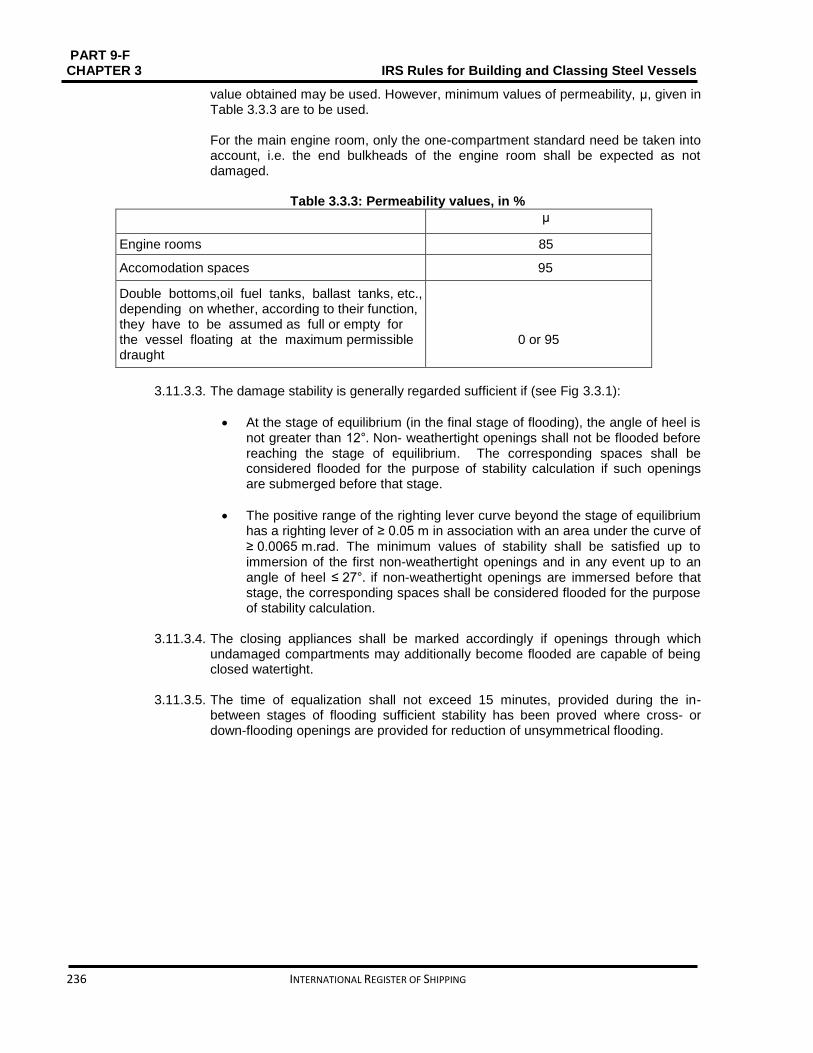
PART 9-F CHAPTER 3 IRS Rules for Building and Classing Steel Vessels
236 INTERNATIONAL REGISTER OF SHIPPING
value obtained may be used. However, minimum values of permeability, μ, given in Table 3.3.3 are to be used. For the main engine room, only the one-compartment standard need be taken into account, i.e. the end bulkheads of the engine room shall be expected as not damaged.
Table 3.3.3: Permeability values, in %
Spaces μ
Engine rooms 85
Accomodation spaces 95
Double bottoms,oil fuel tanks, ballast tanks, etc., depending on whether, according to their function, they have to be assumed as full or empty for the vessel floating at the maximum permissible draught
0 or 95
3.11.3.3. The damage stability is generally regarded sufficient if (see Fig 3.3.1):
At the stage of equilibrium (in the final stage of flooding), the angle of heel is not greater than 12°. Non- weathertight openings shall not be flooded before reaching the stage of equilibrium. The corresponding spaces shall be considered flooded for the purpose of stability calculation if such openings are submerged before that stage.
The positive range of the righting lever curve beyond the stage of equilibrium has a righting lever of ≥ 0.05 m in association with an area under the curve of
≥ 0.0065 m.rad. The minimum values of stability shall be satisfied up to immersion of the first non-weathertight openings and in any event up to an angle of heel ≤ 27°. if non-weathertight openings are immersed before that stage, the corresponding spaces shall be considered flooded for the purpose of stability calculation.
3.11.3.4. The closing appliances shall be marked accordingly if openings through which undamaged compartments may additionally become flooded are capable of being closed watertight.
3.11.3.5. The time of equalization shall not exceed 15 minutes, provided during the in-
between stages of flooding sufficient stability has been proved where cross- or down-flooding openings are provided for reduction of unsymmetrical flooding.
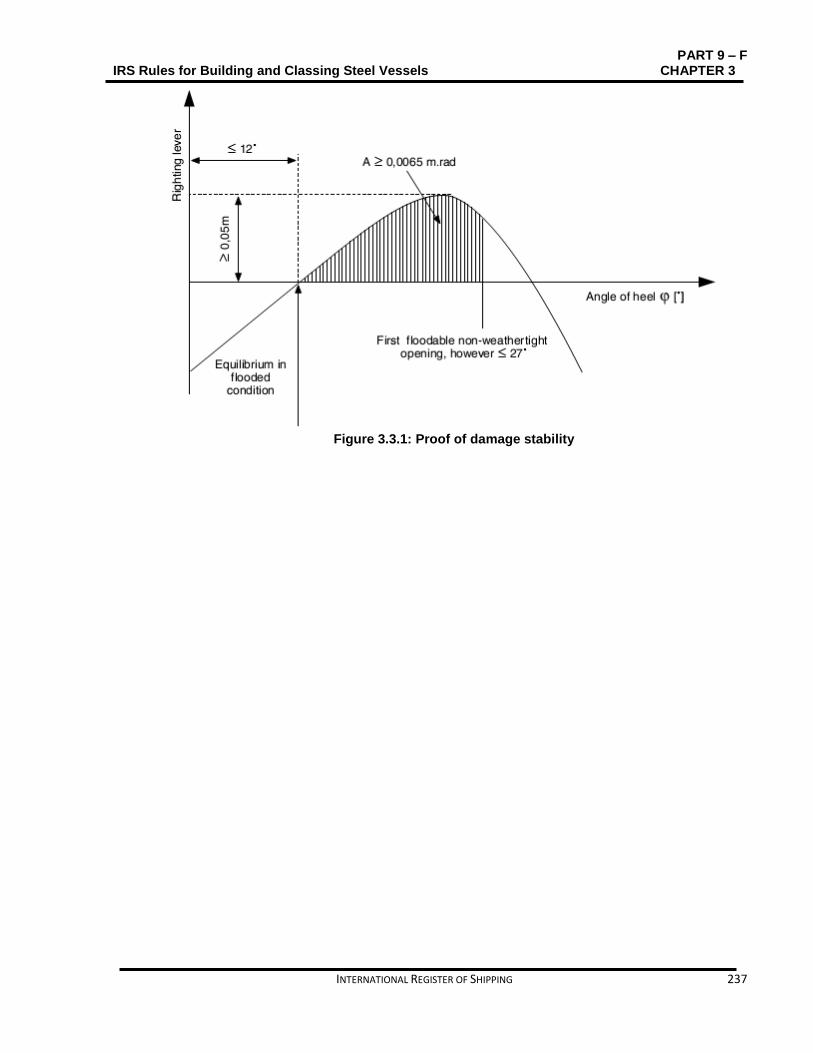
PART 9 – F IRS Rules for Building and Classing Steel Vessels CHAPTER 3
INTERNATIONAL REGISTER OF SHIPPING 237
Figure 3.3.1: Proof of damage stability
PART 9-F CHAPTER 3 IRS Rules for Building and Classing Steel Vessels
238 INTERNATIONAL REGISTER OF SHIPPING
SECTION 4 TYPE N Contents
4.1. General ........................................................................................................................................... 239
4.2. Vessel arrangements ..................................................................................................................... 239
4.3. Cargo containment ......................................................................................................................... 247
4.4. Cargo piping systems ..................................................................................................................... 251
4.5. Cargo pressure and temperature control ....................................................................................... 253
4.6. Receptacles for residual products and receptacles for slops ........................................................ 253
4.7. Environmental control .................................................................................................................... 254
4.8. Electrical installations ..................................................................................................................... 255
4.9. Fire protection and fire extinction ................................................................................................... 258
4.10. Safety and control installations ...................................................................................................... 259
4.11. Buoyancy and stability ................................................................................................................... 261

PART 9 – F IRS Rules for Building and Classing Steel Vessels CHAPTER 3
INTERNATIONAL REGISTER OF SHIPPING 239
4.1. General
4.1.1. Symbols L: Rule length, in m, defined in Part 9 C, Chapter 1, Sec 1, [1.2]
LOA Length overall, in m, defined in Part 9 C, Chapter 1, Sec 1, [1.2] B: Breadth, in m, defined in Part 9 C, Chapter 1, Sec 1, [1.2]
D: Depth, in m, defined in Part 9 C, Chapter 1, Sec 1, [1.2]
T: Draught, in m, defined in Part 9 C, Chapter 1, Sec 1, [1.2]
4.1.2. Application 4.1.2.1. Vessels complying with the requirements of this Section are eligible for the
assignment of the following additional service features:
Type N closed as defined in Part A, Chapter 2, Sec 2, [2.4.2.4].
Type N open with flame arresters as defined in Part A, Chapter 1, Sec 2, [2.4.2.5].
Type N open as defined in Part A, Chapter 2, Sec 2, [2.4.2.6].
4.1.2.2. These Rules apply in addition to Chapter 1, Sec 3 and Chapter 3, Sec 1.
4.1.3. Documents to be submitted 4.1.3.1. Table 3.4.1 lists the plans and documents to be submitted additionally to the
documents needed in the other Parts of the Rules for the parts of the vessel not affected by the cargo, as applicable.
4.2. Vessel arrangements
4.2.1. Protection against the penetration of gases - Type N closed and Type N open with flame arrester 4.2.1.1. The vessel shall be planned so as to prevent gases from penetrating into the
lodging spaces and the service spaces.
4.2.1.2. Outside the cargo area, the lower edges of door openings in the sidewalls of superstructures and the coamings of access hatches to under-deck spaces shall have a height of not less than 0.50 m above the deck. This requirement need not be complied when the wall of the superstructures facing the cargo area extends from one side of the ship to the other and has doors the sills of which have a height of not less than 0.50 m. The height of this wall shall not be less than 2.00 m. In this case, the lower edges of door-openings in the sidewalls of superstructures and of coamings of access hatches behind this wall shall have a height of not less than 0.10 m. The sills of engine room doors and the coamings of its access hatches shall, however, always have a height of not less than 0.50 m.
4.2.1.3. In the cargo area, the lower edges of door-openings in the sidewalls of
superstructures shall have a height of not less than 0.50 m above the deck and the sills of hatches and ventilation openings of premises located under the deck shall have a height of not less than 0.50 m above the deck. This requirement does not apply to access openings to double- hull and double bottom spaces.
4.2.1.4. The bulwarks, foot-rails, etc. shall be given with appropriately large openings which
are situated directly above the deck.

PART 9-F CHAPTER 3 IRS Rules for Building and Classing Steel Vessels
240 INTERNATIONAL REGISTER OF SHIPPING
4.2.2. Engine rooms
4.2.2.1. Internal fire engines for the vessel’s propulsion as well as internal combustion engines for auxiliary machinery shall be positioned outside the cargo area. Entrances and other openings of engine rooms shall be at a distance of not less than 2.00 m from the cargo area.
4.2.2.2. The engine rooms shall be reachable from the deck; the entrances shall not face
the cargo area. When the doors are not placed in a recess whose depth is at least equal to the door width, the hinges shall face the cargo area.
4.2.3. Accommodation and service spaces
4.2.3.1. Accommodation spaces and the wheelhouse shall be situated outside the cargo
area forward of the fore vertical plane or abaft the aft vertical plane bounding the part of cargo area below deck. Windows of the wheelhouse which are positioned not less than 1.00 m above the floor of the wheelhouse may tilt forward.
4.2.3.2. Entrances to spaces and openings of superstructures shall not face the cargo area. Doors opening outward and not situated in a recess the depth of which is at least equal to the width of the doors shall have their hinges facing the cargo area.
4.2.3.3. Entrances from the deck and openings of spaces facing the weather shall be able
of being closed. The following instruction shall be displayed at the entrance of such spaces: "DO NOT OPEN DURING LOADING, UNLOADING OR GAS-FREEING WITHOUT THE PERMISSION OF THE MASTER. CLOSE IMMEDIATELY."

PART 9 – F IRS Rules for Building and Classing Steel Vessels CHAPTER 3
INTERNATIONAL REGISTER OF SHIPPING 241
Table 3.4.1: Plans and documents to be submitted
No A/I Document
1 I Design characteristics of products to be carried, including maximum vapour pressure, maximum liquid cargo tem- perature and other important design conditions
2 I General arrangement plan, showing location of cargo tanks and fuel oil, ballast and other tanks, void spaces
3 A Ventilation duct arrangement in gas-dangerous spaces and adjacent zones
4 A Details of hull structure in way of cargo tanks, including support arrangement for tanks, saddles, anti-floating and anti-lifting devices, deck sealing arrangements, independent cargo tanks, etc.
5 A Intact and damage stability calculations
6 A Scantlings, material and arrangement of the cargo containment system
7 A Details of cargo handling system, including arrangements and details of piping and fittings
8 A Details of cargo pumps
9 A Details of temperature and pressure control systems
10 A Bilge and ballast system in cargo area
11 A Gas freeing system in cargo tanks including inert gas system
12 A Ventilation system in cargo area
13 A Details of electrical equipment installed in cargo area, including the list of certified safe equipment and apparatus and electrical bonding of cargo tanks and piping
14 A Schematic electrical wiring diagram
15 A Pressure drop calculation note
16 A Gas detection system
17 A Cargo tank instrumentation
18 A Details of fire-extinguishing appliances and systems in cargo area
19 A Arrangement drawing of the various fire bulkheads and decks with standard fire test reports for the various arrangements, surface coverings, paints and similar
20 I Loading and unloading operation description, including cargo tank filling limits, where applicable
21 A Gas return system
Note 1: A = to be submitted for review/approval in triplicate I = to be submitted for information in duplicate
4.2.3.4. Entrances and windows of superstructures and accommodation spaces which can be opened as well as other openings of these spaces shall be positioned not less than 2.00 m from the cargo area. No wheelhouse doors and windows shall be situated within 2.00 m from the cargo area, except where there is no direct association between the wheelhouse and the accommodation.
4.2.3.5. Machinery
a) Driving shafts of the bilge or ballast pumps in the cargo area may enter
through the bulkhead between the service space and the engine room, providing the arrangement of the service space is in compliance with [4.2.5.6].
PART 9-F CHAPTER 3 IRS Rules for Building and Classing Steel Vessels
242 INTERNATIONAL REGISTER OF SHIPPING
b) The Society shall approve the penetration of the shaft through the
bulkhead which must be gastight.
c) The necessary operating instructions shall be displayed.
d) Penetrations through the bulkhead between the engine room and the service space in the cargo area, and the bulkhead between the engine room and the hold spaces may be provided for electrical cables, hydraulic and piping for measuring, control and alarm systems, on condition that the penetrations have been permitted by the Society. The penetrations shall be gastight. Penetrations through a bulkhead with “A-60” fire protection insulation, shall have an equivalent fire protection.
e) Pipes may enter the bulkhead between the engine room and the service
space in the cargo area provided that these are pipes between the mechanical equipment in the engine room and the service space which
f) do not have any openings within the service space and which are provided with shut-off devices at the bulkhead in the engine room.
g) Notwithstanding [4.2.5.4], pipes from the engine room may enter the
service space in the cargo area or a cofferdam or a hold space or a double hull space to the outside provided that within the service space or cofferdam or hold space or doublehull space they are of the thick-walled type and have no flanges or openings.
4.2.4. Accommodation and service spaces - additional requirements for Type N closed and Type
N open with flame arrester
4.2.4.1. Where a driving shaft of auxiliary machinery penetrates through a wall located above the deck the penetration shall be gastight.
4.2.4.2. A service space located within the cargo area below deck shall not be used as a
cargo pump room for the loading and unloading system, except where:
the pump-room is separated from the engine room or from service spaces outside the cargo area by a cofferdam or a bulkhead with an “A-60” fire protection insulation, or by a service space or a hold space
The “A-60” bulkhead required above does not contain penetrations referred to in [4.2.3.5] (a)
Ventilation exhaust outlets are located not less than 6.00 m from entrances and openings of the accommodation and service spaces outside the cargo area
The access hatches and ventilation inlets can be closed from the outside
All pipes for loading and unloading as well as those of stripping systems are provided with shut-off devices at the pump suction side in the cargo pump-room immediately at the bulkhead. The necessary operation of the control devices in the pump room, starting of pumps and necessary control of the liquid flow rate shall be effected from the deck

PART 9 – F IRS Rules for Building and Classing Steel Vessels CHAPTER 3
INTERNATIONAL REGISTER OF SHIPPING 243
The bilge of the cargo pump-room is fitted out with a gauging device for measuring the filling level which activates a visual and audible alarm in the wheelhouse when liquid is storing in the cargo pump-room bilge
The cargo pump room is provided with a permanent gas detection system which automatically directs the presence of explosive gases or lack of oxygen by means of direct-measuring sensors and which actuates a visual and audible alarm when the gas concentration has reached 20% of the lower explosive limit. The sensors of this system shall be placed at suitable positions at the bottom and directly below the deck.
Measurement shall be continuous.
The audible and visual alarms are installed in the wheelhouse and in the cargo pump room and, when the alarm is actuated, the loading and unloading system is shut down. Failure of the gas detection system shall be immediately signalled in the wheelhouse and on deck by means of audible and visual alarms
The ventilation system prescribed in [4.2.6.3] has a capacity of not less than 30 changes of air per hour based on the total volume of the service space.
4.2.4.3. The following instruction shall be displayed at the entrance of the cargo pump
room: BEFORE ENTERING THE CARGO PUMP-ROOM CHECK WHETHER IT IS FREE FROM GASES AND CONTAINS SUFFICIENT OXYGEN. DO NOT OPEN DOORS AND ENTRANCE OPENINGS WITHOUT THE PERMISSION OF THE MASTER. LEAVE IMMEDIATELY IN EVENT OF ALARM.
4.2.5. Hold spaces
4.2.5.1. The cargo tanks shall be separated by cofferdams of at least 0.60 m in width from
the accommodation, engine room and service spaces outside the cargo area below deck or, if there are no such accommodation, engine room and service spaces, from the vessel’s ends. A space of not less than 0.50 m shall be provided between such tanks and the end bulkheads of the hold space Where the cargo tanks are installed in a hold space. In this case an end bulkhead meeting at least the definition for Class “A-60”, shall be considered equivalent to a cofferdam. For pressure cargo tanks, the 0.50 m distance may be reduced to 0.20 m.
4.2.5.2. Hold spaces, cofferdams and cargo tanks shall be capable of being checked. 4.2.5.3. All spaces in the cargo area shall be capable of being ventilated. Means for
checking their gas-free condition shall be provided. 4.2.5.4. The bulkheads bounding the cargo tanks, cofferdams and hold spaces shall be
watertight. The cargo tanks and the bulkheads bounding the cargo area shall have no openings or penetrations below deck. The bulkhead between the engine room and the cofferdam or service space in the cargo area or between the engine room and a hold space may be fixed with penetrations provided that they conform to the provisions of [4.2.3.5].
The bulkhead between the cargo tank and the cargo pump room below deck may be fixed with penetrations provided that they follow to the provisions of [4.2.3.6]. The bulkheads between the cargo tanks may be fixed with penetrations on

PART 9-F CHAPTER 3 IRS Rules for Building and Classing Steel Vessels
244 INTERNATIONAL REGISTER OF SHIPPING
condition that the loading or unloading pipes are fixed with shut-off devices in the cargo tank from which they come. The shut-off devices shall be operable from the deck. These pipes shall be at least 0.60 m above the bottom.
4.2.5.5. Double hull spaces and double bottoms in the cargo area shall be prepared for
being filled with ballast water only. Double bottoms may, however, be used as fuel oil tanks, provided they comply with [4.2.9].
4.2.5.6.
a) A cofferdam, the centre part of a cofferdam or another space below deck
in the cargo area may be prepared as a service space, on condition that the bulkheads bounding the service space spread out vertically to the bottom. This service space shall only be accessible from the deck.
b) The service space shall be watertight with the exception of its access hatches and ventilation inlets.
4.2.5.7. Additional requirement for Type N closed and Type N open with flame arrester.
No pipes for loading and unloading shall be fixed within the service space referred to under (a) above.
Pipes for loading and unloading may be fixed in the cargo pump-rooms below deck only when they follow to the provisions of [4.2.4.2].
4.2.5.8. The service spaces shall be arranged so as to be easily accessible and to permit
persons wearing protective clothing and breathing apparatus to safely operate the service equipment contained therein where service spaces are positioned in the cargo area under deck. They shall be planned so as to allow injured or unconscious personnel to be removed from such spaces without difficulty, if necessary by means of fixed equipment.
4.2.5.9. Cofferdams, double-hull spaces, double bottoms, cargo tanks, hold spaces and
other accessible spaces within the cargo area shall be arranged so that they may be completely inspected and cleaned in an appropriate manner. The dimensions of openings except for those of double hull spaces and double bottoms which do not have a wall adjoining the cargo tanks shall be sufficient to allow a person wearing breathing apparatus to enter or leave the space without difficulties. These openings shall have a minimum cross-sectional area of 0.36 𝑚2 and a minimum side length of 0.50 m. They shall be designed so as to allow an injured or unconscious person to be removed from the bottom of such a space without difficulties, if necessary by means of fixed equipment. In these spaces the distance between the reinforcements shall not be less than 0.50 m. In double bottoms this distance may be reduced to 0.45 m. Cargo tanks may have circular openings with a diameter of not less than 0.68 m.
4.2.6. Ventilation
4.2.6.1. Each hold space shall have two openings the dimensions and location of which
shall be such as to allow effective ventilation of any part of the hold space. If there are no such openings, it shall be possible to fill the hold spaces with inert gas or dry air.

PART 9 – F IRS Rules for Building and Classing Steel Vessels CHAPTER 3
INTERNATIONAL REGISTER OF SHIPPING 245
4.2.6.2. Double-hull spaces and double bottoms within the cargo area which are not arranged for being filled with ballast water, hold spaces and cofferdams, shall be arranged for ventilation systems.
4.2.6.3. Any service spaces located in the cargo area below deck shall be provided with a
system of forced ventilation with sufficient power for confirming at least 20 changes of air per hour based on the volume of the space. The ventilation exhaust ducts shall extend down to 50 mm above the bottom of the service space. The air shall be passed through a duct at the top of the service space. The air inlets shall be placed not less than 2.00 m above the deck, at a distance of not less than 2.00 m from tank openings and 6.00 m from the outlets of safety valves. The extension pipes, which may be necessary, may be of the hinged type. On board open type N vessels other suitable installations without ventilator fans shall be adequate.
4.2.6.4. Ventilation of accommodation and service spaces shall be possible.
4.2.7. Ventilation - additional requirements for Type N closed and Type N open with flame
arrester 4.2.7.1. Ventilators used in the cargo area shall be designed so that no sparks may be
released on contact of the impeller blades with the housing and no static electricity may be produced.
4.2.7.2. Notice boards shall be fixed at the ventilation inlets indicating the conditions when
they shall be closed. All ventilation inlets of lodging space and service spaces leading outside shall be fixed with fire flaps. Such ventilation inlets shall be placed not less than 2.00 m from the cargo area. Ventilation inlets of service spaces in the cargo area may be placed within such area.
4.2.7.3. The flame-arresters prescribed in [4.2.14.1], [4.3.7.3] and [4.3.7.5] shall be of a
type approved for this purpose by the Society.
4.2.8. Engines 4.2.8.1. Only internal combustion engines running on fuel with a flashpoint of more than
55 °C are allowed. 4.2.8.2. Ventilation inlets of the engine room and, when the engines do not take in air
straight from the engine room, the air intakes of the engines shall be placed not less than 2.00 m from the cargo area.
4.2.8.3. Sparking shall not be possible within the cargo area. 4.2.8.4. The surface temperature of the outer parts of engines used during loading or
unloading operations, as well as that of their air inlets and exhaust ducts shall not go beyond the allowable temperature according to the temperature class of the substances carried. This provision does not apply to engines installed in service spaces on condition that the provisions of [4.8.3.2] are fully complied with.
4.2.8.5. The ventilation in the closed engine room shall be projected so that, at an ambient
temperature of 20°C, the average temperature in the engine room does not go
beyond 40°C.

PART 9-F CHAPTER 3 IRS Rules for Building and Classing Steel Vessels
246 INTERNATIONAL REGISTER OF SHIPPING
4.2.9. Oil fuel tanks
4.2.9.1. The double bottoms within these spaces may be arranged as oil fuel tanks,
provided their depth is not less than 0.60 m when the vessel is provided with hold spaces. Oil fuel pipes and openings of such tanks are not allowed in the hold space.
4.2.9.2. The open ends of the air pipes of all oil fuel tanks shall outspread to not less than
0.50 m above the open deck. Their open ends and the open ends of overflow pipes leading on the deck shall be fixed with a protective device containing of a gauze diaphragm or a punctured plate.
4.2.10. Exhaust pipes
4.2.10.1. Exhausts shall be expatriated from the vessel into the open air either upwards through an exhaust pipe or through the shell plating. The exhaust outlet shall be located not less than 2,00 m from the cargo area. The exhaust pipes of engines shall be prepared so that the exhausts are led away from the vessel. The exhaust pipes shall not be placed within the cargo area.
4.2.10.2. Exhaust pipes shall be provided with a device preventing the escape of sparks, e.g.
spark arresters.
4.2.11. Bilge pumping and ballasting arrangements
4.2.11.1. Bilge and ballast pumps for spaces within the cargo area shall be installed within such area. This provision does not apply to:
Double hull spaces and double bottoms which do not have a common boundary wall with the cargo tanks;
Cofferdams, double hull spaces, hold spaces and double bottoms where ballasting is performed using the piping of the firefighting system in the cargo area and bilge umping is performed using eductors.
4.2.11.2. Double bottom shall not be connected to the bilge piping system, where it is used as oil fuel tank.
4.2.11.3. The standpipe and its outboard connection for suction of ballast water shall be
located within the cargo area but outside the cargo tanks, where the ballast pump is installed in the cargo area.
4.2.11.4. A cargo pump-room below deck shall be capable of being drained in an emergency
by an installation located in the cargo area and independent from any other installation. This installation shall be done outside the cargo pump room.
4.2.12. Ventilation of cargo pump rooms
4.2.12.1. Cargo pump rooms must be equipped with extraction type ventilation systems,
independent of other vessel's spaces, providing at least 30 cycles of air change per hour. Warning notices shall be placed needing that the ventilation is in operation for at least 15 minutes prior to entering these spaces.
4.2.12.2. Portable means must be provided for gas-freeing of cargo tanks and other spaces
not equipped with fixed ventilation.
PART 9 – F IRS Rules for Building and Classing Steel Vessels CHAPTER 3
INTERNATIONAL REGISTER OF SHIPPING 247
4.2.13. Arrangements of cofferdams
4.2.13.1. Cofferdams or cofferdam compartments remaining once a service space has been set in accordance with [4.2.5.6] and [4.2.5.7] shall be accessible through an access hatch. If, on the other hand, the cofferdam is connected to a double-hull space, it is sufficient for it to be accessible from that space.
4.2.13.2. Cofferdams shall be capable of being filled with water and emptied by means of a
pump. Filling shall be made within 30 minutes. These requirements are not applicable when the bulkhead between the engine room and the cofferdam comprises fire-protection insulation “A- 60”, or has been fitted out as a service space. The cofferdams shall not be fixed with inlet valves.
4.2.13.3. No fixed pipe shall permit connection between a cofferdam and other piping of the
vessel outside the cargo area.
4.2.14. Arrangement of cofferdams–additional requirement for Type N closed and Type N open with flame arrester The ventilation openings of cofferdams shall be fixed with a flame-arrester enduring a deflagration.
4.3. Cargo containment
4.3.1. General 4.3.1.3. Type N may be arranged in three different designs regarding cargo tank venting
with due regard to the products allowed to be carried:
Type N, open venting
Type N, open venting, flame arresters
Type N, closed. 4.3.1.4. The scantlings and structural arrangements are to be fulfilling applicable requisites
of Chapter 1, Sec 3, [3.3] to Chapter 1, Sec 3, [3.7].
4.3.2. Cargo area hull design
4.3.2.1. The space between the wall of the vessel and wall of the cargo tanks shall be not less than 0.60 m, where independent cargo tanks are used, or for double- hull construction where the cargo tanks are integrated in vessel’s structure. The space between the bottom of the vessel and the bottom of the cargo tanks shall be not less than 0.50 m. The spaces may be reduced to 0.40 m under the pump sumps. The vertical space between the suction well of a cargo tank and the bottom structures shall be not less than 0.10 m.
The above values are appropriate to the double hull, when a hull is constructed in the cargo area as a double hull with independent cargo tanks located in hold spaces. If in this case the minimum values for examinations of independent tanks referred to in [4.2.5.9] are not practicable, it must be possible to remove the cargo tanks easily for inspection.
4.3.2.2. They shall be arranged so as to be easily accessible and to permit persons
wearing protective clothing and breathing apparatus to safely operate the service equipment contained therein Where service spaces are located in the cargo area under deck. They shall be designed so as to allow injured or unconscious personnel to be removed from such spaces without difficulties, if necessary by means of fixed equipment.

PART 9-F CHAPTER 3 IRS Rules for Building and Classing Steel Vessels
248 INTERNATIONAL REGISTER OF SHIPPING
4.3.3. Cargo tank sizes 4.3.3.3. In accordance with Table 3.4.2, the maximum allowable capacity of a cargo tank
for single hull tank vessels, double hull tank vessels and vessels with tanks independent of the hull shall be determined
where: LOAB D: Product of the tank vessel main dimensions, in m3
LOA ∶ overall length of the hull, in m In the case of trunk deck vessels, D’ is to be
substituted for D. D’ is to be determined by the following formula:
D'= D + h
btlt
𝐵𝐿𝑂𝐴
where: ht: Height, in m, of trunk (distance between trunk deck and main deck on trunk
side measured at LOA/2)
bt: Trunk breadth, in ml lt: Trunk length, in m
4.3.3.4. Alternative constructions in compliance with Chapter 3, ******* are permitted.
Table 4.2.2: Tank sizes
LOA , B, D in m3 μ
<600 0.3LOABD
From 600 to 3750 180 + (LOA B D - 600) 0.0635 95
> 3750 380
4.3.4. Cargo tank arrangements
4.3.4.1. The cargo tank is to comply with the following:
For vessels with a length not more than 50.00 m, the length of a cargo tank shall not exceed 10.00 m
For vessels with a length of more than 50.00 m, the length of a cargo tank shall not exceed 0.20 L, where L is the vessel rule length. This provision
does not apply to vessels with independent built-in cylindrical tanks having a length to diameter ratio ≤ 7.
4.3.4.2. The volume of a suction well shall be limited to not more than 0.10 m3.
4.3.5. Integrated tank scantlings The scantlings of the integrated tank structure are to be determined in compliance with Chapter 1, Sec 3.
4.3.6. Independent cargo tank scantlings
4.3.6.1. Tank scantlings
The scantlings of independent cargo tank structure are to be determined in compliance with Chapter 1, Sec 3, [3.4.1.3]. These tanks shall be designed in compliance with Part D, Chapter 3, when the vessel is provided with pressure cargo tanks for a working pressure of 400 kPa.

PART 9 – F IRS Rules for Building and Classing Steel Vessels CHAPTER 3
INTERNATIONAL REGISTER OF SHIPPING 249
4.3.6.2. Supports and fastenings
The cargo tanks independent of the vessel’s hull shall be fixed in such way that they cannot float.
4.3.7. Cargo tank openings 4.3.7.1.
a) Cargo tank openings shall be located on deck in the cargo area.
b) Cargo tank openings with a cross-section of more than 0.10 m2 and openings of safety devices for preventing overpressures shall be placed not less than 0.50 m above deck.
4.3.7.2. For Type N closed, cargo tank openings shall be fixed with gastight closures capable of enduring the test pressure in accordance with Part 9C, Chapter 2, Sec 8.
4.3.7.3. Safety devices
Each cargo tank or group of cargo tanks linked to a common vapour pipe shall be fixed with safety devices for preventing unacceptable overpressures or vacuums. These safety devices shall be as follows:
a) For Type N open
Safety devices designed to prevent any collection of water and its penetration into the cargo tanks
b) For Type N open with flame arresters
Safety equipment fitted with flame-arresters capable of enduring steady burning and designed to prevent any accumulation of water and its penetration into the cargo tank
c) For Type N closed
Safety devices for preventing unacceptable overpressures or vacuums. When anti-explosion protection is required, the vacuum valve shall be fitted with a flame arrester capable of withstanding a deflagration and the pressure-relief valve with a high-velocity vent valve acting as a flame arrester capable of withstanding steady burning.
The gases shall be discharged upwards. The opening pressure of the high-velocity vent valve and the opening pressure of the vacuum valve shall be indelibly indicated on the valves LOAB D, in m3
Maximum permissible capacity of a cargo tank, in m³
a connection for the safe return ashore of gases expelled during loading
a device for the safe depressurisation of the tanks consisting of at least a flame arrester and a stop valve which clearly indicates whether it is open or shut.
4.3.7.4. Additional arrangement for safety devices fitted on Type N closed
The outlets of high-velocity vent valves shall be placed not less than 2.00 m above the deck and at a distance of not less than 6.00 m from the lodging space and from
PART 9-F CHAPTER 3 IRS Rules for Building and Classing Steel Vessels
250 INTERNATIONAL REGISTER OF SHIPPING
the service spaces outside the cargo area. This height may be reduced when within a radius of 1.00 m round the outlet of the high-velocity vent valve, there is no equipment, no work is being performed and signs indicate the area. The setting of the high-velocity vent valves shall be such that during the transport operation they do not blow off until the maximum permissible working pressure of the cargo tanks is reached.
4.3.7.5. Additional arrangements for anti-explosion protection fitted on Type N closed
a) Insofar as anti-explosion protection is recommended, a vapour pipe connecting two or more cargo tanks shall be fixed, at the connection to each cargo tank, with a flame arrester with a fixed or spring-loaded plate stack, capable of enduring a detonation. This equipment may consist of:
A flame arrester fitted with a fixed plate stack, where each cargo tank is fixed with a vacuum valve capable of enduring a deflagration and a high-velocity vent valve capable of withstanding steady burning
A flame arrester fitted with a spring-loaded plate stack, where each cargo tank is fitted with a vacuum valve capable of withstanding a deflagration
A flame arrester with a fixed plate stack
A flame arrester with a fixed plate stack, where the pressure-measuring device is fitted with an alarm system in accordance with [4.10.5]
A flame arrester with a spring-loaded plate stack, where the pressure-measuring device is fixed with an alarm system in accordance with [4.10.5]. Only substances which do not mix and which do not react dangerously with each other may be carried at the same time in cargo tanks connected to a common vapour pipe.
or b) Insofar as anti-explosion protection is suggested, a vapour pipe
connecting two or more cargo tanks shall be fixed, at the connection to each cargo tank, with a pressure/vacuum relief valve including a flame arrester capable of enduring a detonation/deflagration. Only substances which do not mix and which do not react dangerously with each other may be carried at the same time in cargo tanks connected to a common vapour pipe.
or c) Insofar as anti-explosion protection is prescribed, an independent vapour
pipe for each cargo tank, fitted with a pressure/vacuum valve incorporating a flame arrester capable of withstanding a deflagration and a high velocity vent valve incorporating a flame arrester capable of withstanding steady burning. Several different substances may be carried simultaneously.
or d) Insofar as anti-explosion protection is recommended, a vapour pipe
connecting two or more cargo tanks shall be fixed, at the connection to each cargo tank, with a shut-off device capable of enduring a detonation, where each cargo tank is fixed with a vacuum valve capable of withstanding a deflagration and a high velocity vent valve capable of withstanding steady burning. Only substances which do not mix and which do not react dangerously with each other may be carried at the same time in cargo tanks connected to a common vapour pipe.
PART 9 – F IRS Rules for Building and Classing Steel Vessels CHAPTER 3
INTERNATIONAL REGISTER OF SHIPPING 251
4.3.7.6. Additional requirement for Type N closed and Type N open with flame arrester
Closures which are generally used during loading or unloading operations shall not cause sparking when operated.
4.4. Cargo piping systems
4.4.1. General
4.4.1.1. The requirements [4.4.1.2], [4.4.1.4], [4.4.2.2] [4.4.2.5], [4.4.2.8] and [4.4.4.1] do not apply to Type N open unless the substance carried has corrosive properties.
4.4.1.2. Pumps and accessory loading and unloading piping shall be placed in the cargo
area. 4.4.1.3. Cargo pumps shall be capable of being shut down from the cargo area and from a
position outside the cargo area. 4.4.1.4. Cargo pumps situated on deck shall be located not less than 6.00 m from
entrances to, or openings of, the accommodation and service spaces outside the cargo area.
4.4.2. Arrangement of cargo piping
4.4.2.1. Pipes for loading and unloading shall be independent of any other piping of the vessel.
4.4.2.2. No cargo piping shall be positioned below deck, except those inside the cargo
tanks and inside the cargo pump room. 4.4.2.3. The pipes for loading and unloading shall be arranged so that, after loading or
unloading operations, the liquid remaining in these pipes may be safely detached and may flow either into the vessel’s tanks or the tanks ashore.
4.4.2.4. Piping for loading and unloading shall be clearly different from other piping, e.g. by
means of colour marking. 4.4.2.5. The shore connections shall be positioned not less than 6,00 m from the entrances
to or openings of, the lodging space and service spaces outside the cargo area. 4.4.2.6. Each shore connection of the vapour pipe and shore connections of the pipes for
loading and unloading, through which the loading or unloading operation is performed, shall be fixed with a shut-off device. However, each shore connection shall be fixed with a blind flange when it is not in operation.
Pipes for loading and unloading, and vapour pipes, shall not have flexible connections fixed with sliding seals.
4.4.2.7. The distance referred to in [4.4.1.4] and [4.4.2.5] may be reduced to 3.00 m if a
transverse bulkhead complying with [4.2.1.2] is situated at the end of the cargo area. The openings shall be provided with doors. The following notice shall be displayed on the doors: DO NOT OPEN DURING LOADING AND UNLOADING WHITHOUT THE PERMISSION OF THE MASTER. CLOSE IMMEDIATELY.

PART 9-F CHAPTER 3 IRS Rules for Building and Classing Steel Vessels
252 INTERNATIONAL REGISTER OF SHIPPING
4.4.2.8. A separate pump with its own piping for loading and unloading shall be installed for each substance if the vessel is carrying several dangerous substances liable to react dangerously with each other. The piping shall not cross a cargo tank containing dangerous substances with which the substance in question is liable to react.
4.4.3. Control, monitoring and alarm devices
4.4.3.1. Stop valves
The stop valves or other shut-off devices of the pipes for loading and unloading shall show whether they are open or shut.
4.4.3.2. Pressure gauges
The pipes for loading and unloading shall be fixed with pressure gauges at the outlet of the pumps. The allowable maximum overpressure or vacuum value shall be specified on each measuring device. Readings shall be possible in all weather conditions.
4.4.4. Bonding
Every component of the pipes for loading and unloading shall be electrically joined to the hull.
4.4.5. Supply of cargo tanks with washing or ballast water
4.4.5.1. The suctions of these pipes shall be positioned within the cargo area but outside
the cargo tanks when pipes for loading and unloading are used for supplying the cargo tanks with washing or ballast water. Pumps for tank washing systems with related connections may be located outside the cargo area, provided the discharge side of the system is arranged in such a way that suction is not possible through that part. A spring-loaded non-return valve shall be attached to prevent any gases from being expelled from the cargo area through the tank washing system.
4.4.5.2. A non-return valve shall be fixed at the junction between the water suction pipe and
the cargo loading pipe.
4.4.6. Permissible loading and unloading flows
4.4.6.1. The allowable loading and unloading flows shall be calculated. For open type N with flame-arrester and open type N the loading and unloading flows depend on the total cross-section of the exhaust ducts.
4.4.6.2. Taking into account the design of the ventilation system calculations concern the
permissible maximum loading and unloading flow for each cargo tank or each group of cargo tanks. These calculations shall take into consideration the fact that in the event of an unexpected cut-off of the gas return piping or the compensation piping of the shore facility, the safety devices of the cargo tanks will stop pressure in the cargo tanks from exceeding the following values:
over-pressure: 115% of the opening pressure of the high-velocity vent valve;
vacuum pressure: not more than the construction vacuum pressure but not exceeding 5 kPa
4.4.7. Additional requirements for Type N closed and Type N open with flame arrester
Filling pipes for cargo tanks are to extend down as close as possible to the bottom of the tank.

PART 9 – F IRS Rules for Building and Classing Steel Vessels CHAPTER 3
INTERNATIONAL REGISTER OF SHIPPING 253
4.5. Cargo pressure and temperature control
4.5.1. Cargo tank heating
4.5.1.1. Cargo tank heating system is to be fitted as a distinct system, equipped with a heat
exchanger positioned in the cargo area. Where special heat transfer media are used this requirement may be distributed with upon approval by the Society.
4.5.1.2. Boilers which are used for heating the cargo shall be fuelled with a liquid fuel
having a flashpoint of more than 55°C. They shall be located either in the engine room or in another separate space below deck and outside the cargo area, which is accessible from the deck or from the engine room.
4.5.1.3. The cargo heating system shall be planned so that the cargo cannot penetrate into
the boiler in the case of a leak in the heating coils. A cargo heating system with artificial draught shall be burned electrically.
4.5.1.4. The ventilation system of the engine room shall be designed taking into account
the air required for the boiler. 4.5.1.5. The service space which contains this system shall fully comply with the
requirements of [4.8.3.1] b) where the cargo heating system is used during loading, unloading or gas-freeing. These necessities do not apply to the inlets of the ventilation system. These inlets shall be positioned at a minimum distance of 2.00 m from the cargo area and 6.00 m from the openings of cargo tanks or residual cargo tanks, loading pumps positioned on deck, openings of high velocity vent valves, pressure relief devices and shore connections of loading and unloading pipes and must be located not less than 2.00 m above the deck.
The requirements of [4.8.3.1] b) are not applicable to the unloading of substances having a flash point of 60 °C or more when the temperature of the product is at least 15 K lower at the flash point.
4.5.2. Water spray system
4.5.2.1. When water-spraying is required in column (9) of Table C of ADN Chapter 3.2, a
water-spray system shall be fitted in the cargo area on deck for the purpose of cooling the tops of cargo tanks by spraying water over the whole surface so as to avoid safely the activation of the high-velocity vent valve at 10 kPa or as regulated.
4.5.2.2. The spray nozzles shall be so fitted that the entire cargo deck area is covered and
the gases released are lead to safely. The system shall be capable of being put into operation from the wheelhouse and from the deck. Its capacity shall be such that when all the spray nozzles are in operation, the outflow is not less than 50 litres per square metre of deck area and per hour.
4.6. Receptacles for residual products and receptacles for slops
4.6.1. General
4.6.1.1. If vessels are provided with a tank for residual products, it shall fulfill the provisions
of [4.6.1.3] to [4.6.1.7].

PART 9-F CHAPTER 3 IRS Rules for Building and Classing Steel Vessels
254 INTERNATIONAL REGISTER OF SHIPPING
Receptacles for residual products and receptacles for slops shall be positioned only in the cargo area. During the filling of the receptacles for residual products, means for collecting any leakage shall be retained under the filling connections.
4.6.1.2. Receptacles for slops shall be fire resistant and shall be capable of being closed
with lids. The receptacles for slops shall be marked and easy to handle.
4.6.1.3. The maximum capacity of a tank for residual products is 30 m3. 4.6.1.4. The tank for residual products shall be equipped with:
a) In the case of an open system
A device for ensuring pressure equilibrium
An ullage opening
Connections, with stop valves, for pipes and hoses
b) In the case of a protected system
A device for ensuring pressure equilibrium, fitted with a flame-arrester capable of withstanding steady burning
An ullage opening
Connections, with stop valves, for pipes and hoses
c) In the case of a closed system
A vacuum valve and a high-velocity vent valve
The high velocity vent valve shall be so controlled as not to open during carriage. This condition is met when the opening pressure of the valve meets the conditions required in column (10) of Table C of ADN Chapter 3.2. The vacuum valve shall be capable of enduring deflagrations and the high velocity vent valve shall endure steady burning, when anti-explosion protection is needed in column (17) of Table C of ADN Chapter 3.2,
A device for measuring the degree of filling
Connections with shut-off devices, for pipes and hoses.
4.6.1.5. Receptacles for residual products shall be equipped with:
A connection enabling gases released during filling to be evacuated safely
A possibility of indicating the degree of filling
Connections with shut-off devices, for pipes and hoses.
4.6.1.6. Receptacles for residual products shall be linked to the vapour pipe of cargo tanks only for the time required to fill them.
4.6.1.7. Receptacles for residual products and receptacles for slops placed on the deck
shall be located at a minimum distance from the hull equal to one quarter of the vessel’s breadth.
4.7. Environmental control
4.7.1. Inerting facility 4.7.1.1. In cases in which inerting or blanketing of the cargo is recommended, the vessel
shall be equipped with an inerting system.

PART 9 – F IRS Rules for Building and Classing Steel Vessels CHAPTER 3
INTERNATIONAL REGISTER OF SHIPPING 255
4.7.1.2. This system shall be capable of maintaining a permanent minimum pressure of 7 kPa (0.07 bar) in the spaces to be inerted. Additionally, the inerting system shall not raise the pressure in the cargo tank to a pressure greater than that at which the pressure valve is controlled. The set pressure of the vacuum-relief valve shall be 3.5 kPa (0.035 bar).
4.7.1.3. A sufficient quantity of inert gas for loading or unloading shall be carried or
produced on board if it is not possible to attain it on shore. Additionally, a sufficient quantity of inert gas to offset normal losses occurring during carriage shall be on board.
4.7.1.4. The premises to be inerted shall be prepared with connections for introducing the
inert gas and monitoring systems so as to confirm the correct atmosphere on a permanent basis.
4.7.1.5. This monitoring system shall activate an audible and visible alarm in the
wheelhouse, when the pressure or the concentration of inert gas in the gaseous phase falls below a given value. When the wheelhouse is unoccupied, the alarm shall also be perceptible in a location occupied by a crew member.
4.8. Electrical installations
4.8.1. Documents to be kept on board
Additionally to the documents required in Part E, Chapter 1, Sec 1, [1.2] and section 4, the following documents shall be on board: a) A drawing indicating the boundaries of the cargo area and the location of the electrical
equipment installed in this area
b) A list of the electrical equipment referred to in (a) above including the following particulars: machine or appliance, location, type of protection, type of protection against explosion, testing body and approval number
c) A list of or general plan indicating the electrical equipment outside the cargo area which may be operated during loading, unloading or gas-freeing. All other electrical equipment shall be marked in red.
4.8.2. General design requirements
4.8.2.1. Only distribution systems without return connection to the hull are allowed. This
provision does not apply to:
Certain limited sections of the installations situated outside the cargo area connections of starters of diesel engines)
Device for checking the insulation level referred to in [4.8.2.2]
Active cathodic corrosion protection.
4.8.2.2. Each insulated distribution network shall be fixed with an automatic device with a visual and audible alarm for inspecting the insulation level.
4.8.2.3. For the variation of electrical equipment to be used in zones presenting an
explosion risk, the explosion groups and temperature classes allocated to the substances carried shall be taken into consideration.
PART 9-F CHAPTER 3 IRS Rules for Building and Classing Steel Vessels
256 INTERNATIONAL REGISTER OF SHIPPING
4.8.3. Type and location of electrical equipment
4.8.3.1. a) Only measuring, regulation and alarm devices of the EEx (ia) type of protection
may be fixed in cargo tanks, residual cargo tanks and pipes for loading and unloading (comparable to zone 0)
b) Only the following equipment may be fixed in the cofferdams, double-hull spaces, double bottoms and hold spaces (comparable to zone 1):
Measuring, regulation and alarm devices of the certified safe type
Lighting appliances of the “flame-proof enclosure” or “pressurised enclosure” type of protection
Hermetically sealed echo sounding devices the cables of which are led through thick-walled steel tubes with gastight connections up to the main deck
Cables for the active cathodic protection of the shell plating in protective steel tubes such as those provided for echo sounding devices
c) Only the following equipment may be fixed in the service spaces in the cargo area
below deck (comparable to zone 1):
Measuring, regulation and alarm devices of the certified safe type
Lighting appliances of the “flame-proof enclosure” or “apparatus protected by pressurization” type of protection
Motors driving essential equipment such as ballast pumps; they shall be of the certified safe type
d) The control and protective equipment of the electrical equipment referred to in
paragraphs (a), (b) and (c) above shall be located outside the cargo area if they are not intrinsically safe
e) The electrical equipment in the cargo area on deck (comparable to zone 1) shall be
of the certified safe type. 4.8.3.2.
a) Electrical equipment used during loading, unloading and gas-freeing during berthing and which are located outside the cargo area shall (comparable to zone 2) be at least of the “limited explosion risk” type.
b) This provision does not apply to:
Lighting installations in the accommodation, except for switches near entrances to accommodation
Radiotelephone installations in the accommodation or the wheelhouse
Electrical installations in the accommodation, the wheelhouse or the service spaces outside the cargo areas if:
These spaces are fitted with a ventilation system ensuring an overpressure of 0,1 kPa (0,001 bar) and none of the windows is capable of being opened; the air intakes of the ventilation system shall be located as far away as possible, however, not less than 6,00 m from the cargo area and not less than 2,00 m above the deck
The spaces are fitted with a gas detection system with sensors:
PART 9 – F IRS Rules for Building and Classing Steel Vessels CHAPTER 3
INTERNATIONAL REGISTER OF SHIPPING 257
- At the suction inlets of the ventilation system - Directly at the top edge of the sill of the entrance doors of the accommodation and service spaces
The gas concentration measurement is continuous
The ventilators are switched off when the gas concentration reaches 20% of the lower explosive limit. In such a case and when the overpressure is not sustained or in the event of failure of the gas detection system, the electrical installations which do not fulfill (a) above, shall be switched off. These operations shall be carried out immediately and automatically and activate the emergency lighting in the accommodation, the wheelhouse and the service spaces, which shall fulfill at least with the “limited explosion risk” type. The switching-off shall be indicated in the accommodation and wheelhouse by visual and audible signals
The ventilation system, the gas detection system and the alarm of the switch-off device fully comply with the requirements of (a) above
The automatic switching-off device is set in such way that no automatic switch off may happen while the vessel is under way.
4.8.3.3. The electrical equipment which does not meet the requirements depart in [4.8.3.2]
together with its switches shall be marked in red. The disconnection of such equipment shall be operated from a centralised location on board.
4.8.3.4. A permanent electric engine generator which does not meet the requirements of
[4.8.3.2] shall be fixed with a switch capable of shutting down the excitation of the generator. A notice board with the operating instructions shall be shown near the switch.
4.8.3.5. Sockets for the connection of signal lights and gangway lighting shall be
permanently fixed to the vessel close to the signal mast or the gangway. Connecting and disconnecting shall not be possible except when the sockets are not live.
4.8.3.6. The failure of the power supply for the safety and control equipment shall be
instantly specified by visual and audible signals at the locations where the alarms are generally actuated.
4.8.4. Earthing
4.8.4.1. The metal parts of electrical appliances in the cargo area which are not live as well
as protective metal tubes or metal sheaths of cables in normal service shall be earthed, unless they are so arranged that they are automatically earthed by bonding to the metal structure of the vessel.
4.8.4.2. The provisions of [4.8.4.1] above apply also to equipment having service voltages
of less than 50 𝑉. 4.8.4.3. Independent cargo tanks, metal intermediate bulk containers and tank-containers
shall be earthed. 4.8.4.4. Receptacles for residual products shall be capable of being earthed.
4.8.5. Electrical cables
4.8.5.1. All cables in the cargo area shall have a metallic sheath.
PART 9-F CHAPTER 3 IRS Rules for Building and Classing Steel Vessels
258 INTERNATIONAL REGISTER OF SHIPPING
4.8.5.2. Cables and sockets in the cargo area shall be protected against mechanical
damage. 4.8.5.3. Movable cables are banned in the cargo area, except for essentially safe electric
circuits or for the supply of signal lights, gangway lighting. 4.8.5.4. Cables of essentially safe circuits shall only be used for such circuits and shall be
disconnected from other cables not intended for being used in such circuits (e.g. they shall not be installed together in the same string of cables and they shall not be fixed by the same cable clamps).
4.8.5.5. Only sheathed cables of type H 07 RN-F in accordance with standard IEC 60 245-
4:1994 or cables of at least equal design having conductors with a cross-section of
not less than 1,5 mm2 shall be used for portable cables intended for signal lights or gangway lighting. These cables shall be as short as possible and installed so that damage is not likely to happen.
4.8.5.6. The cables required for the electrical equipment referred to in [4.8.3.1] b) and
[4.8.3.1] c) are accepted in cofferdams, double hull spaces, double bottoms, hold spaces and service spaces below deck.
4.8.6. Storage batteries
Storage batteries shall be located outside the cargo area.
4.9. Fire protection and fire extinction
4.9.1. Fire and naked light 4.9.1.1. The outlets of funnels shall be positioned not less than 2.00 m from the cargo area.
Arrangements shall be provided to prevent the escape of sparks and the entry of water.
4.9.1.2. Heating, cooking and refrigerating appliances shall not be fuelled with liquid fuels,
liquid gas or solid fuels.
The set up in the engine room or in another separate space of heating appliances fuelled with liquid fuel having a flash-point above 55 °C is, though, permitted. Cooking and refrigerating appliances are allowable only in the lodging space.
4.9.1.3. Only electrical lighting appliances are permitted.
4.9.2. Prohibition of smoking, fire or naked light
4.9.2.1. In accordance with ADN Regulations Section 8.3.4, the notice boards displaying the prohibition of smoking shall be clearly legible from either side of the vessel.
4.9.2.2. Notice boards demonstrating the circumstances under which the prohibition is
applicable shall be fitted near the entrances to the spaces where smoking or the use of fire or naked light is not always prohibited.
4.9.3. Fire extinguishing arrangements
Additionally to the requirements of Part C, Chapter 3, the fire extinguishing arrangements in [4.9.4] to [4.9.6] are to be complied with.

PART 9 – F IRS Rules for Building and Classing Steel Vessels CHAPTER 3
INTERNATIONAL REGISTER OF SHIPPING 259
4.9.4. Portable fire extinguishers
Additionally to the fire-extinguishing appliances prescribed in Part D, Chapter 15, Sec 2, [2.6], the vessel shall be equipped with at least two additional portable fire-extinguishers having the same capacity in cargo area. These additional portable fire-extinguishers shall be suitable for fighting fires involving the dangerous goods carried.
4.9.5. Fire extinguishing system
A fire-extinguishing system shall fulfill the following requirements shall be installed on the vessel.
It shall be supplied by two independent fire or ballast pumps, one of which shall be prepared for use at any time. These pumps and their means of propulsion and electrical equipment shall not be set up in the same space
It shall be provided with a water main fitted with at least three hydrants in the cargo area above deck. Three suitable and sufficiently long hoses with spray nozzles having a diameter of not less than 12 mm shall be provided
It shall be possible to reach any point of the deck in the cargo area at the same time with at least two jets of water not supplied from the same hydrant. A spring-loaded non-return valve shall be fixed to confirm that no gases can escape through the fire extinguishing system into the lodging space or service spaces outside the cargo area.
The capacity of the system shall be at least adequate for a jet of water to have a minimum reach of not less than the vessel's breadth from any location on board with.
Two spray nozzles being used concurrently.
4.9.1. Fixed fire extinguishing system
Additionally, the engine rooms, the pump room and all spaces holding essential equipment (switchboards, compressors, etc.) for the refrigeration equipment, if any, shall be provided with a permanently fixed fire-extinguishing system, in compliance with Part D, Chapter 15, Sec 3, [2.6].
4.10. Safety and control installations 4.10.1. General
Cargo tanks shall be provided with the following equipment:
a) A mark inside the tank indicating the liquid level of 97% b) A level gauge c) A level alarm device which is activated at the latest when a degree of filling of 90% is
reached d) A high level sensor for actuating the facility against overflowing at the latest when a
degree of filling of 97.5% is reached e) For Type N closed, an instrument for measuring the pressure of the vapour phase
inside the cargo tank f) An instrument for measuring the temperature of the cargo g) A connection for a sampling device.
4.10.2. Cargo tank level indicators
Each cargo tank is to be equipped with a closed gauging device approved by the Society. When the degree of filling in per cent is determined, an error of not more than 0.5% is permitted. It shall be calculated on the basis of the total cargo tank capacity including the expansion trunk. The level gauge shall permit readings from the control position of the shut-

PART 9-F CHAPTER 3 IRS Rules for Building and Classing Steel Vessels
260 INTERNATIONAL REGISTER OF SHIPPING
off devices of the particular cargo tank. The allowable maximum filling level of the cargo tank shall be marked on each level gauge. Permanent reading of the overpressure and vacuum shall be possible from a location from which loading or unloading operations may be disturbed. The permissible maximum overpressure and vacuum shall be marked on each level gauge. Readings shall likely to be done in all weather conditions.
4.10.3. Level alarm device
Cargo tank shall be provided with a level alarm device which is activated at the latest when a degree of filling of 90% is reached. The level alarm device shall give a visual and audible warning on board when actuated. The level alarm device shall be independent of the level gauge. The visual and audible signals given by the level alarm device shall be clearly distinguishable from those of the high level sensor. The visual alarm shall be visible at each control position on deck of the cargo tank stop valves. It shall be possible to easily check the functioning of the sensors and electric circuits or these shall be “intrinsically safe apparatus”.
4.10.4. High level sensor
Cargo tank shall be provided with a high level sensor for actuating the facility against overflowing at the latest when a degree of filling of 97, 5% is reached.
4.10.5. Cargo tank pressure monitoring
4.10.5.1. The requirements of this Sub-article apply to Type N closed. 4.10.5.2. Instruments for measuring the vacuum or overpressure of the gaseous phase in
the cargo tank or the temperature of the cargo shall activate a visual and audible alarm in the wheelhouse when the pressure or temperature goes beyond a set value. The alarm shall also be noticeable in a location occupied by a crew member when the wheelhouse is unoccupied the alarm shall also be perceptible in a location occupied by a crew member.
4.10.5.3. The instrument for measuring the overpressure or vacuum shall initiate the alarm at
latest when an overpressure equal to 1.15 times the opening pressure of the pressure relief device, or a vacuum pressure equal to the construction vacuum pressure but not exceeding 5 kPa. The maximum permissible temperature is specified in column (20) of Table C of ADN Regulations Chapter 3.2. The sensors for the alarms stated in this paragraph may be connected to the alarm device of the sensor.
4.10.5.4. When it is prescribed in column (20) of Table C of ADN Regulations Chapter 3.2,
the instrument for measuring the overpressure of the gaseous phase shall actuate a visible and audible alarm in the wheelhouse when the overpressure exceeds 40 kPa during the journey. The alarm shall also be noticeable in a location occupied by a crew member when the wheelhouse is unoccupied.
4.10.6. Cargo temperature monitoring
An appliance for measuring the temperature of the cargo shall be provided, if in column (9) of Table C of ADN Regulations Chapter 3.2 a heating installation is required, or if an opportunity of heating the cargo is required, if a maximum temperature is specified in column (20) of that list. Temperature specifying devices in each cargo tank shall be provided for the mean temperature of the cargo.

PART 9 – F IRS Rules for Building and Classing Steel Vessels CHAPTER 3
INTERNATIONAL REGISTER OF SHIPPING 261
4.10.7. Cargo tank sampling equipment
Each cargo tank shall be equipped with a connection for a sampling device, closed or partially closed, and/or at least one sampling opening as required in column (13) of Table C of ADN of Chapter 3.2.
4.11. Buoyancy and stability
4.11.1. General
4.11.1.1. General requirements of Part 9 C, Chapter 8, are to be fulfilled. 4.11.1.2. The longitudinal centre bulkhead may be dispensed with only if sufficient stability is
guaranteed. 4.11.1.3. Proof of sufficient stability shall be furnished. This proof is not required for single
hull vessels with cargo tanks the width of which is not more than 0.70B. 4.11.1.4. The basic values for the stability calculation (the vessel’s lightweight and location of
the centre of gravity) shall be determined in compliance with Part 9 C, Chapter 8, Sec 3.
4.11.1.5. Proof of intact stability is to be provided for all loading/ unloading stages and for the
final loading condition. 4.11.1.6. Floatability after damage shall be proved for the most undesirable loading
condition. For this purpose, calculated proof of sufficient stability shall be established for critical intermediate stages of flooding and for the final stage of flooding.
Negative values of stability in intermediate stages of flooding may be accepted only if the continued range of curve of the righting lever in damaged condition indicates adequate positive values of stability.
4.11.2. Intact stability
4.11.2.1. For vessels with independent cargo tanks and for double hull constructions with cargo tanks combined in the frames of the vessel, the requirements for intact stability resulting from the damage stability calculation shall be fully fulfilled.
4.11.2.2. For vessels with cargo tanks of more than 0.70 B in width, the following intact
stability requirements are to be complied with, bearing in mind the influence of all free surfaces in tanks for all stages of loading and unloading:
In the positive area of the righting lever curve up to immersion of the first non-watertight opening there shall be a righting lever (GZ) of not less than 0.10 m
The surface of the positive area of the righting lever curve up to immersion of the first non-watertight opening and in any event up to an angle of heel ≤ 27° shall not be less than 0,024 m.rad
The initial meta-centric height GM0 shall be not less than 0.10 m. 4.11.3. Damage stability
4.11.3.1. For vessels with independent cargo tanks and for double hull constructions with cargo tanks combined in the frames of the vessel, the following assumptions shall be taken into consideration for the damaged condition.
PART 9-F CHAPTER 3 IRS Rules for Building and Classing Steel Vessels
262 INTERNATIONAL REGISTER OF SHIPPING
a) Extent of side damage:
Longitudinal extent: at least 0.10 LOA but not less than 5.00 m
Transverse extent: 0.59 m
Vertical extent: from base line upwards without limit
b) Extent of bottom damage:
Longitudinal extent: at least 0,10 LOA but not less than 5.00 m
Transverse extent: 3.00 m
Vertical extent: from base line to 0.49 m upwards, except for pump well.
c) Any bulkhead within the damaged area shall be anticipated damaged,
which means that the location of bulkheads shall be selected to ensure that the vessel remains afloat after the flooding of two or more adjacent compartments in the longitudinal direction. The following provisions are applicable:
For bottom damage, adjacent athwartship compartments shall also be assumed flooded
The lower edge of any non-watertight opening (e.g. windows, doors and access hatchways) shall, at the final stage of flooding, be not less than 0.10 m above the damage waterline.
4.11.3.2. Generally, permeability shall be assumed to be 95%. Where an average
permeability of less than 95%is calculated for any compartment, this calculated value obtained may be used. However, minimum values of permeability, μ , given in Table 4.3.3 are to be used. For the main engine room, only the one-compartment standard need be taken into account, i.e. the end bulkheads of the engine room shall be anticipated as not damaged.
4.11.3.3. The damage stability is generally regarded sufficient if (see Fig 3.4.3):
At the stage of equilibrium (in the final stage of flooding), the angle of heel is not greater than 12°. Non- weathertight openings shall not be flooded before reaching the stage of equilibrium. The corresponding spaces shall be considered flooded for the purpose of stability calculation if such openings are submerged before that stage.
The positive range of the righting lever curve beyond the stage of equilibrium has a righting lever of ≥ 0.05 m in association with an area under the curve of ≥ 0.0065 m.rad. The minimum values of stability shall be satisfied up to immersion of the first non-weather tight openings and in any event up to an angle of heel ≤ 27°. if non-weather tight openings are immersed before that stage, the corresponding spaces shall be considered flooded for the purpose of stability calculation.
4.11.3.4. The closing appliances shall be marked accordingly if openings through which undamaged compartments may additionally become flooded are capable of being closed watertight.

PART 9 – F IRS Rules for Building and Classing Steel Vessels CHAPTER 3
INTERNATIONAL REGISTER OF SHIPPING 263
4.11.3.5. The time of equalization shall not exceed 15 minutes, provided during the in-between stages of flooding sufficient stability has been proved where cross- or down-flooding openings are provided for reduction of unsymmetrical flooding.
Table 3.4.3: Permeability values, in %
Spaces μ
Engine rooms 85
Accommodation spaces 95
Double bottoms,oil fuel tanks, ballast tanks, etc., depending on whether, according to their function, they have to be assumed as full or empty for the vessel floating at the
0 or 95
Figure 3.4.1: Proof of damage stability

PART 9-F CHAPTER 3 IRS Rules for Building and Classing Steel Vessels
264 INTERNATIONAL REGISTER OF SHIPPING
SECTION 5 OIL SEPARATOR VESSEL Contents
5.1. General ........................................................................................................................................... 265
5.2. Vessel arrangement ....................................................................................................................... 266
5.3. Cargo containment ......................................................................................................................... 270
5.4. Cargo piping system ...................................................................................................................... 272
5.5. Cargo temperature control ............................................................................................................. 273
5.6. Receptacles for residual products and receptacles for slops ........................................................ 273
5.7. Electrical installations ..................................................................................................................... 273
5.8. Fire protection and fire extinction ................................................................................................... 277
5.9. Safety and control installations ...................................................................................................... 278
5.10. Buoyancy and stability ................................................................................................................... 278

PART 9 – F IRS Rules for Building and Classing Steel Vessels CHAPTER 3
INTERNATIONAL REGISTER OF SHIPPING 265
5.1. General
5.1.1. Symbols
L: Rule length, in m, defined in Part 9 C, Chapter 1, Sec 1, [1.2] LOA Length overall, in m, defined in Part 9 C, Chapter 1, Sec 1, [1.2]]
B: Breadth, in m, defined in Part 9 C, Chapter 1, Sec 1, [1.2]
D: Depth, in m, defined in Part 9 C, Chapter 1, Sec 1, [1.2]
T: Draught, in m, defined in Part 9 C, Chapter 1, Sec 1, [1.2]
5.1.2. Application
5.1.2.1. Vessels complying with the requirements of this Section are eligible for the assignment of the additional service feature Type N open - Oil separator vessel as defined in Part A, Chapter 2, Sec 2, [2.4.2.9].
5.1.2.2. These Rule requirements apply in addition to Chapter 1, Sec 3 and Chapter 3, Sec
1. 5.1.2.3. Vessels without cargo tanks are considered to be subject to Chapter 3, Sec 7.
5.1.3. Documents to be submitted Table 3.5.1 lists the plans and documents to be submitted additionally to the documents needed in the other Parts of the Rules for the parts of the vessel not affected by the cargo, as applicable.
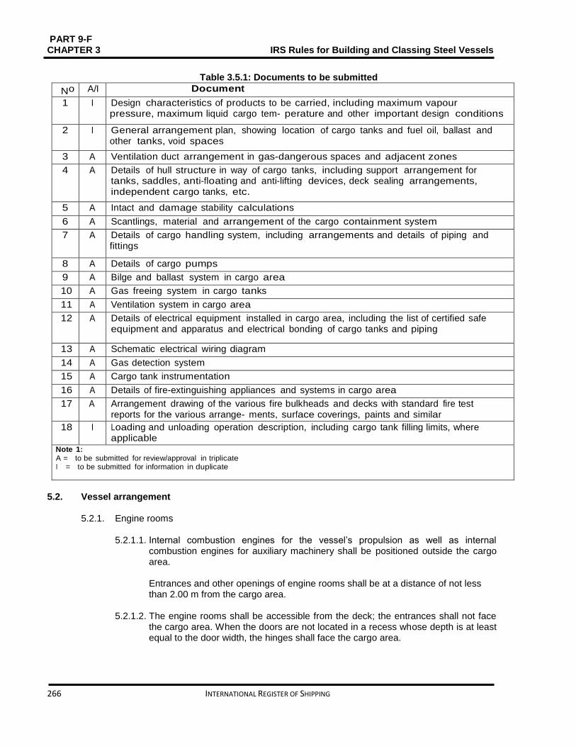
PART 9-F CHAPTER 3 IRS Rules for Building and Classing Steel Vessels
266 INTERNATIONAL REGISTER OF SHIPPING
Table 3.5.1: Documents to be submitted
No A/I Document
1 I Design characteristics of products to be carried, including maximum vapour pressure, maximum liquid cargo tem- perature and other important design conditions
2 I General arrangement plan, showing location of cargo tanks and fuel oil, ballast and other tanks, void spaces
3 A Ventilation duct arrangement in gas-dangerous spaces and adjacent zones
4 A Details of hull structure in way of cargo tanks, including support arrangement for tanks, saddles, anti-floating and anti-lifting devices, deck sealing arrangements, independent cargo tanks, etc.
5 A Intact and damage stability calculations
6 A Scantlings, material and arrangement of the cargo containment system
7 A Details of cargo handling system, including arrangements and details of piping and fittings
8 A Details of cargo pumps
9 A Bilge and ballast system in cargo area
10 A Gas freeing system in cargo tanks
11 A Ventilation system in cargo area
12 A Details of electrical equipment installed in cargo area, including the list of certified safe equipment and apparatus and electrical bonding of cargo tanks and piping
13 A Schematic electrical wiring diagram
14 A Gas detection system
15 A Cargo tank instrumentation
16 A Details of fire-extinguishing appliances and systems in cargo area
17 A Arrangement drawing of the various fire bulkheads and decks with standard fire test reports for the various arrange- ments, surface coverings, paints and similar
18 I Loading and unloading operation description, including cargo tank filling limits, where applicable
Note 1: A = to be submitted for review/approval in triplicate I = to be submitted for information in duplicate
5.2. Vessel arrangement
5.2.1. Engine rooms
5.2.1.1. Internal combustion engines for the vessel’s propulsion as well as internal combustion engines for auxiliary machinery shall be positioned outside the cargo area.
Entrances and other openings of engine rooms shall be at a distance of not less than 2.00 m from the cargo area.
5.2.1.2. The engine rooms shall be accessible from the deck; the entrances shall not face the cargo area. When the doors are not located in a recess whose depth is at least equal to the door width, the hinges shall face the cargo area.

PART 9 – F IRS Rules for Building and Classing Steel Vessels CHAPTER 3
INTERNATIONAL REGISTER OF SHIPPING 267
5.2.2. Accommodation and service spaces
5.2.2.1. Accommodation spaces and the wheelhouse shall be situated outside the cargo area forward of the fore vertical plane or abaft the aft vertical plane bounding the part of cargo area below deck. Windows of the wheelhouse which are positioned not less than 1.00 m above the floor of the wheelhouse may tilt forward.
5.2.2.2. Entrances to spaces and openings of superstructures shall not face the cargo area. 5.2.2.3. Entrances from the deck and openings of spaces facing the weather shall be
capable of being closed. 5.2.2.4. Machinery
a) Driving shafts of the bilge or ballast pumps in the cargo area may enter through the
bulkhead between the service space and the engine room, provided the arrangement of the service space is in compliance with [5.2.3.6].
b) The Society shall approve the penetration of the shaft through the bulkhead which must be gastight.
c) The necessary operating instructions shall be displayed.
d) Penetrations through the bulkhead between the engine room and the service space in the cargo area, and the bulkhead between the engine room and the hold spaces may be provided for electrical cables, hydraulic and piping for measuring, control and alarm systems, on condition that the penetrations have been permitted by the Society. The penetrations shall be gastight. Penetrations through a bulkhead with “A-60” fire protection insulation, shall have an equivalent fire protection.
e) Pipes may enter the bulkhead between the engine room and the service space in the cargo area provided that these are pipes between the mechanical equipment in the engine room and the service space which do not have any openings within the service space and which are provided with shut-off devices at the bulkhead in the engine room.
f) Notwithstanding [5.2.3.4], pipes from the engine room may enter the service space in the cargo area or a cofferdam or a hold space or a double-hull space to the outside provided that within the service space or cofferdam or hold space or doublehull space they are of the thick-walled type and have no flanges or openings.
5.2.3. Hold spaces
5.2.3.1. The cargo tanks shall be separated by cofferdams of at least 0.60 m in width from the accommodation, engine room and service spaces outside the cargo area below deck or, when there are no such accommodation, engine room and service spaces, from the vessel’s ends. A space of not less than 0.50 m shall be provided between such tanks and the end bulkheads of the hold space where the cargo tanks are installed in a hold space. In this case an end bulkhead meeting at least the definition for Class “A-60”, shall be considered equivalent to a cofferdam. For pressure cargo tanks, the 0.50 m distance may be reduced to 0.20 m.
5.2.3.2. Hold spaces, cofferdams and cargo tanks shall be capable of being checked. 5.2.3.3. All spaces in the cargo area shall be capable of being ventilated. Means for
checking their gas-free condition shall be provided.
PART 9-F CHAPTER 3 IRS Rules for Building and Classing Steel Vessels
268 INTERNATIONAL REGISTER OF SHIPPING
5.2.3.4. The bulkheads bounding the cargo tanks, cofferdams and hold spaces shall be
watertight. The cargo tanks and the bulkheads bounding the cargo area shall have no openings or penetrations below deck.
The bulkhead between the engine room and the cofferdam or service space in the cargo area or between the engine room and a hold space may be fixed with penetrations provided that they conform to the provisions of [5.2.2.4].
The bulkheads between the cargo tanks may be fixed with penetrations on condition that the loading and unloading pipes are fixed with shut-off devices in the cargo tank from which they come. The shut-off devices shall be operable from the deck. These pipes shall be at least 0.60 m above the bottom.
5.2.3.5. Double hull spaces and double bottoms in the cargo area shall be prepared for
being filled with ballast water only. Double bottoms may, however, be used as fuel oil tanks, provided they comply with [5.2.6].
5.2.3.6.
a) A cofferdam, the centre part of a cofferdam or another space below deck in the cargo area may be prepared as a service space, on condition that the bulkheads bounding the service space spread out vertically to the bottom. This service space shall only be accessible from the deck.
b) The service space shall be watertight with the exception of its access hatches and
ventilation inlets. 5.2.3.7. The service spaces shall be arranged so as to be easily accessible and to permit
persons wearing protective clothing and breathing apparatus to safely operate the service equipment contained therein where service spaces are positioned in the cargo area under deck. They shall be planned so as to allow injured or unconscious personnel to be removed from such spaces without difficulty, if necessary by means fixed equipment.
Cofferdams, double-hull spaces, double bottoms, cargo tanks, hold spaces and other accessible spaces within the cargo area shall be arranged so that they may be completely inspected and cleaned in an appropriate manner. The dimensions of openings except for those of double hull spaces and double bottoms which do not have a wall adjoining the cargo tanks shall be sufficient to allow a person wearing breathing apparatus to enter or leave the space without difficulties. These
openings shall have a minimum cross-sectional area of 0.36 𝑚2 and a minimum side length of 0.50 m. They shall be designed so as to allow an injured or unconscious person to be removed from the bottom of such a space without difficulties, if necessary by means of fixed equipment. In these spaces the distance between the reinforcements shall not be less than 0.50 m. In double bottoms this distance may be reduced to 0.45 m. Cargo tanks may have circular openings with a diameter of not less than 0.68 m.
5.2.4. Ventilation
5.2.4.1. Each hold space shall have two openings the dimensions and location of which
shall be such as to allow effective ventilation of any part of the hold space. If there are no such openings, it shall be possible to fill the hold spaces with inert gas or dry air.

PART 9 – F IRS Rules for Building and Classing Steel Vessels CHAPTER 3
INTERNATIONAL REGISTER OF SHIPPING 269
5.2.4.2. Double-hull spaces and double bottoms within the cargo area which are not
arranged for being filled with ballast water, hold spaces and cofferdams, shall be arranged for ventilation systems.
5.2.4.3. Any service spaces located in the cargo area below deck shall be provided with a
system of forced ventilation with sufficient power for confirming at least 20 changes of air per hour based on the volume of the space. The ventilation exhaust ducts shall extend down to 50 mm above the bottom of the service space. The air shall be passed through a duct at the top of the service space. The air inlets shall be placed not less than 2.00 m above the deck, at a distance of not less than 2.00 m from tank openings and 6.00 m from the outlets of safety valves. The extension pipes, which may be necessary, may be of the hinged type. On board open type N vessels other suitable installations without ventilator fans shall be adequate.
5.2.4.4. Ventilation of accommodation and service spaces shall be possible.
5.2.5. Engines 5.2.5.1. Only internal combustion engines running on fuel with a flashpoint of more than
55 °C are allowed. 5.2.5.2. Ventilation inlets of the engine room and, when the engines do not take in air
directly from the engine room, the air intakes of the engines shall be placed not less than 2.00 m from the cargo area.
5.2.5.3. Sparking shall not be possible within the cargo area. 5.2.5.4. The surface temperature of the outer parts of engines used during loading or
unloading operations, as well as that of their air inlets and exhaust ducts shall not go beyond the allowable temperature according to the temperature class of the substances carried. This provision does not apply to engines installed in service spaces on condition that the provisions of [5.7.3.2] are fully complied with.
5.2.5.5. The ventilation in the closed engine room shall be projected so that, at an ambient
temperature of 20°C, the average temperature in the engine room does not go
beyond 40 °C.
5.2.6. Oil fuel tanks 5.2.6.1. The double bottoms within these spaces may be arranged as oil fuel tanks,
provided their depth is not less than 0.60 m when the vessel is provided with hold spaces. Oil fuel pipes and openings of such tanks are not allowed in hold space.
5.2.6.2. The open ends of the air pipes of all oil fuel tanks shall outspread to not less than
0.50 m above the open deck. Their open ends and the open ends of overflow pipes leading on the deck shall be fixed with a protective device containing of a gauze diaphragm or a punctured plate.
5.2.7. Exhaust pipes
5.2.7.1. Exhausts shall be expatriated from the vessel into the open air either upwards through an exhaust pipe or through the shell plating. The exhaust outlet shall be located not less than 2.00 m from the cargo area. The exhaust pipes of engines shall be prepared so that the exhausts are led away from the vessel. The exhaust pipes shall not be placed within the cargo area.

PART 9-F CHAPTER 3 IRS Rules for Building and Classing Steel Vessels
270 INTERNATIONAL REGISTER OF SHIPPING
5.2.7.2. Exhaust pipes shall be provided with a device preventing the escape of sparks, e.g. spark arresters.
5.2.8. Bilge pumping and ballasting arrangements
5.2.8.1. Bilge and ballast pumps for spaces within the cargo area shall be installed within such area. This provision does not apply to:
Double-hull spaces and double bottoms which do not have a common boundary wall with the cargo tanks;
Cofferdams, double hull spaces, hold spaces and double bottoms where ballasting is performed using the piping of the firefighting system in the cargo area and bilge pumping is performed using eductors.
5.2.8.2. Double bottom shall not be connected to the bilge piping system, where it is used
as oil fuel tank. 5.2.8.3. The standpipe and its outboard connection for suction of ballast water shall be
located within the cargo area but outside the cargo tanks, where the ballast pump is installed in the cargo area.
5.2.8.4. A cargo pump-room below deck shall be capable of being drained in an emergency
by an installation located in the cargo area and independent from any other installation. This installation shall be done outside the cargo pump room.
5.2.9. Ventilation of cargo pump rooms
5.2.9.1. Cargo pump rooms must be equipped with extraction type ventilation systems,
independent of other vessel's spaces, providing at least 30 cycles of air change per hour. Warning notices shall be placed needing that the ventilation is in operation for at least 15 minutes prior to entering these spaces.
5.2.9.2. Portable means must be provided for gas-freeing of cargo tanks and other spaces
not equipped with fixed ventilation.
5.2.10. Arrangements of cofferdams
5.2.10.1. Cofferdams or cofferdam compartments remaining once a service space has been arranged in accordance with [5.2.3.6] shall be accessible through an access hatch. If, on the other hand, the cofferdam is connected to a double-hull space, it is sufficient for it to be accessible from that space.
5.2.10.2. No fixed pipe shall permit connection between a cofferdam and other piping of the
vessel outside the cargo area.
5.3. Cargo containment
5.3.1. General The scantlings and structural arrangements are to be in compliance with applicable requirements of Chapter 1, Sec 3.
5.3.2. Cargo area hull design
5.3.2.1. The space between the wall of the vessel and wall of the cargo tanks shall be not
less than 0.60 m, where independent cargo tanks are used, or for double- hull construction where the cargo tanks are integrated in vessel’s structure. The space

PART 9 – F IRS Rules for Building and Classing Steel Vessels CHAPTER 3
INTERNATIONAL REGISTER OF SHIPPING 271
between the bottom of the vessel and the bottom of the cargo tanks shall be not less than 0.50 m. The spaces may be reduced to 0.40 m under the pump sumps. The vertical space between the suction well of a cargo tank and the bottom structures shall be not less than m.
The above values are appropriate to the double hull, when a hull is constructed in the cargo area as a double hull with independent cargo tanks located in hold spaces. If in this case the minimum values for examinations of independent tanks referred to in [5.2.3.8] are not practicable, it must be possible to remove the cargo tanks easily for inspection.
5.3.2.2. They shall be arranged so as to be easily accessible and to permit persons
wearing protective clothing and breathing apparatus to safely operate the service equipment contained therein when service spaces are located in the cargo area under deck. They shall be designed so as to allow injured or unconscious personnel to be removed from such spaces without difficulties,, if necessary by means of fixed equipment.
5.3.3. Cargo tank sizes
5.3.3.1. In accordance with Table 3.5.2, the maximum allowable capacity of a cargo tank
for single hull tank vessels, double hull tank vessels and vessels with tanks independent of the hull shall be determined.
where: LOAB D: Product of the tank vessel main dimensions, in m3
LOA ∶ overall length of the hull, in m In the case of trunk deck vessels, D’ is to be
substituted for D. D’ is to be determined by the following formula:
D'= D + h
btlt
BLOA
where: ht: Height, in m, of trunk (distance between trunk deck and main deck on trunk side measured at LOA/2)
bt: Trunk breadth, in ml
lt: Trunk length, in m 5.3.3.2. Alternative constructions will be permitted on case by case basis.
Table 3.5.2: Tank sizes
LOA B D, in m3 Maximum permissible capacity of a cargo tank, in m3
< 600 0.3 LOA B D
from 600 to 3750 180 + (LOA B D - 600) 0,0635
> 3750 380
5.3.4. Cargo tank arrangements
5.3.4.1. The cargo tank is to comply with the following:
For vessels with a length not more than 50.00 m, the length of a cargo tank shall not exceed 10.00 m
For vessels with a length of more than 50.00 m, the length of a cargo tank shall not exceed 0.20 L, where L is the vessel rule length. This provision
PART 9-F CHAPTER 3 IRS Rules for Building and Classing Steel Vessels
272 INTERNATIONAL REGISTER OF SHIPPING
does not apply to vessels with independent built-in cylindrical tanks having a length to diameter ratio ≤ .
5.3.4.2. The capacity of a suction well shall be limited to not more than 0.10 m3.
5.3.5. Integrated tank scantlings
The scantlings of the integrated tank structure are to be determined in compliance with Chapter 1, Sec 3.
5.3.6. Independent cargo tank scantlings
5.3.6.1. Cargo tank scantlings
The scantlings of independent cargo tanks are to be determined in compliance with Chapter 1, Sec 3, [3.4.1.3].
5.3.6.2. Supports and fastenings
The scantlings of the tank supports and fastenings are to be in compliance with Chapter 1, Sec 3.
5.3.7. Cargo tank openings
5.3.7.1.
a) Cargo tank openings shall be located on deck in the cargo area. b) Cargo tank openings with a cross-section of more than 0.10 m2 and openings of
safety devices for preventing overpressures shall be located not less than 0.50 m above deck.
5.3.7.2. Safety devices
Each cargo tank or group of cargo tanks connected to a common vapour pipe shall be fitted with safety devices designed to prevent any accumulation of water and its penetration into the cargo tanks.
5.4. Cargo piping system
5.4.1. Arrangement for cargo pumps
Cargo pumps shall be capable of being shut down from the cargo area and from a position outside the cargo area.
5.4.2. Arrangement of cargo piping - general
5.4.2.1. Pipes for loading and unloading shall be independent of any other piping of the
vessel. 5.4.2.2. The pipes for loading and unloading shall be arranged so that, after loading or
unloading operations, the liquid remaining in these pipes may be safely detached and may flow either into the vessel’s tanks or the tanks ashore.
5.4.2.3. Piping for loading and unloading shall be clearly different from other piping, e.g. by
means of colour marking.

PART 9 – F IRS Rules for Building and Classing Steel Vessels CHAPTER 3
INTERNATIONAL REGISTER OF SHIPPING 273
5.4.2.4. Each shore connection of the vapour pipe and shore connections of the pipes for loading and unloading, through which the loading or unloading operation is performed, shall be fixed with a shut-off device.
5.4.2.5. Pipes for loading and unloading, and vapour pipes, shall not have flexible
connections fitted with sliding seals.
5.4.3. Control and monitoring
5.4.3.1. Stop valves
The stop valves or other shut-off devices of the pipes for loading and unloading shall indicate whether they are open or shut.
5.4.4. Supply of cargo tanks with washing or ballast water
5.4.4.1. The suctions of these pipes shall be positioned within the cargo area but outside
the cargo tanks when pipes for loading and unloading are used for supplying the cargo tanks with washing or ballast water. Pumps for tank washing systems with related connections may be located outside the cargo area, provided the discharge side of the system is arranged in such a way that suction is not possible through that part. A spring-loaded non-return valve shall be attached to prevent any gases from being expelled from the cargo area through the tank washing system.
5.4.4.2. A non-return valve shall be fixed at the junction between the water suction pipe and
the cargo loading pipe.
5.5. Cargo temperature control
5.5.1. Cargo tank heating
5.5.1.1. Cargo tank heating system is to be fitted as a distinct system, equipped with a heat exchanger positioned in the cargo area. Where special heat transfer media are used this requirement may be distributed with upon approval by the by the Society.
5.5.1.2. Boilers which are used for heating the cargo shall be fuelled with a liquid fuel
having a flashpoint of more than 55°C. They shall be located either in the engine room or in another separate space below deck and outside the cargo area, which is accessible from the deck or from the engine room.
5.5.1.3. The cargo heating system shall be planned so that the cargo cannot penetrate into
the boiler in the case of a leak in the heating coils. A cargo heating system with artificial draught shall be burned electrically.
5.5.1.4. The ventilation system of the engine room shall be designed taking into account
the air required for the boiler.
5.6. Receptacles for residual products and receptacles for slops
5.6.1. General
Receptacles for slops shall be fire resistant and shall be capable of being closed with lids. The tanks shall be marked and easy to handle.
5.7. Electrical installations
5.7.1. Documents to be kept on board

PART 9-F CHAPTER 3 IRS Rules for Building and Classing Steel Vessels
274 INTERNATIONAL REGISTER OF SHIPPING
Additionally to the documents required in accordance with the Regulations referred to in Part 9 E, Chapter 1, Sec 1, [1.2] and Sec 4 the following documents shall be on board:
a) A drawing clearly indicating the boundaries of the cargo area and the location of
the electrical equipment set up in this area
b) A list of the electrical equipment referred to in (a) above including the following particulars: machine or appliance, location, type of protection, type of protection against explosion, testing body and approval number
c) A list of or general plan indicating the electrical equipment outside the cargo area
which may be run during loading, unloading or gas-freeing. All other electrical equipment shall be marked in red.
5.7.2. General design requirements
5.7.3.1. Only distribution systems without return connection to the hull are allowed. This provision does not apply to:
Certain limited sections of the installations situated outside the cargo area (connections of starters of diesel engines)
Device for checking the insulation level referred to in [5.7.2.2]
Active cathodic corrosion protection.
5.7.3.2. Every insulated distribution network shall be fixed with an automatic device with a visual and audible alarm for checking the insulation level.
5.7.3.3. For the selection of electrical equipment to be used in zones presenting an
explosion risk, the explosion groups and temperature classes allocated to the substances carried shall be taken into consideration.
5.7.3. Type and location of electrical equipment
5.7.3.1.
a) Only measuring, regulation and alarm devices of the EEx (ia) type of protection may be set up in cargo tanks, residual cargo tanks and pipes for loading and unloading (comparable to zone 0)
b) Only the following equipment may be fixed in the cofferdams, double-hull spaces, double bottoms and hold spaces (comparable to zone 1):
Measuring, regulation and alarm devices of the certified safe type
Lighting appliances of the “flame-proof enclosure” or “pressurised enclosure” type of protection
Hermetically sealed echo sounding devices the cables of which are led through thick-walled steel tubes with gastight connections up to the main deck
Cables for the active cathodic protection of the shell plating in protective steel tubes such as those provided for echo sounding devices
c) Only the following equipment may be set up in the service spaces in the cargo area
below deck (comparable to zone 1):
Measuring, regulation and alarm devices of the certified safe type
Lighting appliances of the “flame-proof enclosure” or “apparatus protected by pressurization” type of protection

PART 9 – F IRS Rules for Building and Classing Steel Vessels CHAPTER 3
INTERNATIONAL REGISTER OF SHIPPING 275
Motors driving essential equipment such as ballast pumps; they shall be of the certified safe type
d) The control and protective equipment of the electrical equipment referred to in
paragraphs (a), (b) and (c) above shall be located outside the cargo area if they are not intrinsically safe
e) The electrical equipment in the cargo area on deck (comparable to zone 1) shall be
of the certified safe type.
5.7.3.2.
a) Electrical equipment used during loading, unloading and gas-freeing during berthing and which are located outside the cargo area shall (comparable to zone 2) be at least of the “limited explosion risk” type.
b) This provision does not apply to:
Lighting installations in the accommodation, except for switches near entrances to accommodation
Radiotelephone installations in the accommodation or the wheelhouse
Electrical installations in the accommodation, the wheelhouse or the service spaces outside the cargo areas if:
These spaces are fitted with a ventilation system ensuring an overpressure of 0.1 k Pa (0,001 bar) and none of the windows is capable of being opened; the air intakes of the ventilation system shall be located as far away as possible, however, not less than 6,00 m from the cargo area and not less than 2.00 m above the deck
The spaces are fitted with a gas detection system with sensors:
- At the suction inlets of the ventilation system - Directly at the top edge of the sill of the entrance doors of the
accommodation and service spaces
The gas concentration measurement is continuous
The ventilators are switched off when the gas concentration reaches 20% of the lower explosive limit. In such a case and when the overpressure is not sustained or in the event of failure of the gas detection system, the electrical installations which do not fulfill (a) above, shall be switched off. These operations shall be carried out immediately and automatically and activate the emergency lighting in the accommodation, the wheelhouse and the service spaces, which shall fulfill at least with the “limited explosion risk” type. The switching-off shall be indicated in the accommodation and wheelhouse by visual and audible signals
The ventilation system, the gas detection system and the alarm of the switch-off device fully comply with the requirements of (a) above
The automatic switching-off device is set in such way that no automatic switch off may occur while the vessel is under way.
5.7.3.3. The electrical equipment which does not meet the requirements depart in [5.8.3.2]
together with its switches shall be marked in red. The disconnection of such equipment shall be operated from a centralised location on board.

PART 9-F CHAPTER 3 IRS Rules for Building and Classing Steel Vessels
276 INTERNATIONAL REGISTER OF SHIPPING
5.7.3.4. A permanent electric engine generator which does not meet the requirements of [5.8.3.2] shall be fixed with a switch capable of shutting down the excitation of the generator. A notice board with the operating instructions shall be shown near the switch.
5.7.3.5. Sockets for the connection of signal lights and gangway lighting shall be
permanently fixed to the vessel close to the signal mast or the gangway. Connecting and disconnecting shall not be possible except when the sockets are not live.
5.7.3.6. The failure of the power supply for the safety and control equipment shall be
instantly specified by visual and audible signals at the locations where the alarms are generally actuated.
5.7.4. Earthing
5.7.4.1. The metal parts of electrical appliances in the cargo area which are not live as well
as protective metal tubes or metal sheaths of cables in normal service shall be earthed, unless they are so arranged that they are automatically earthed by bonding to the metal structure of the vessel.
5.7.4.2. The provisions of [5.7.4.1] above apply also to equipment having service voltages
of less than 50 V. 5.7.4.3. Independent cargo tanks, metal intermediate bulk containers and tank-containers
shall be earthed. 5.7.4.4. Receptacles for residual products shall be capable of being earthed.
5.7.5. Electrical cables
5.7.5.1. All cables in the cargo area shall have a metallic sheath. 5.7.5.2. Cables and sockets in the cargo area shall be protected against mechanical
damage. 5.7.5.3. Movable cables are prohibited in the cargo area, except for intrinsically safe
electric circuits or for the supply of signal lights, gangway lighting. 5.7.5.4. Cables of intrinsically safe circuits shall only be used for such circuits and shall be
separated from other cables not intended for being used in such circuits (e.g. they shall not be installed together in the same string of cables and they shall not be fixed by the same cable clamps).
5.7.5.5. The metal parts of electrical appliances in the cargo area which are not live as well
as protective metal tubes or metal sheaths of cables in normal service shall be earthed, unless they are so arranged that they are automatically earthed by bonding to the metal structure of the to happen.
5.7.5.6. The cables required for the electrical equipment referred to in [5.8.3.1] b) and
[5.8.3.1] c) are accepted in cofferdams, double hull spaces, double bottoms, hold spaces and service spaces below deck.
5.7.6. Storage batteries
Storage batteries shall be located outside the cargo area.
PART 9 – F IRS Rules for Building and Classing Steel Vessels CHAPTER 3
INTERNATIONAL REGISTER OF SHIPPING 277
5.8. Fire protection and fire extinction
5.8.1. Fire and naked light 5.8.1.1. The outlets of funnels shall be located not less than 2.00 m from the cargo area.
Arrangements shall be provided to prevent the escape of sparks and the entry of water.
5.8.1.2. Heating, cooking and refrigerating appliances shall not be fuelled with liquid fuels,
liquid gas or solid fuels. The installation in the engine room or in another separate space of heating appliances fuelled with liquid fuel having a flash-point above 55 °𝐶 is, though, permitted. Cooking and refrigerating appliances are allowed only in the lodging space.
5.8.1.3. Only electrical lighting appliances are permitted.
5.8.2. Prohibition of smoking, fire or naked light 5.8.2.1. In accordance with ADN Regulations Section 8.3.4, the notice boards displaying
the prohibition of smoking shall be clearly legible from either side of the vessel. 5.8.2.2. Notice boards demonstrating the circumstances under which the prohibition is
applicable shall be fixed near the entrances to the spaces where smoking or the use of fire or naked light is not always prohibited.
5.8.3. Fire extinguishing arrangements
Additionally to the requirements of Part 9D, Chapter 15, the fire extinguishing arrangements in [5.8.4] to [5.8.6] are to be complied with.
5.8.4. Portable fire extinguishers Additionally to the fire-extinguishing appliances prescribed in Part 9D, Chapter 15 , Sec 2, [2.4], the vessel shall be equipped with at least two additional portable fire-extinguishers having the same capacity in cargo area. These additional portable fire-extinguishers shall be suitable for fighting fires involving the dangerous goods carried.
5.8.5. Fire extinguishing system A fire extinguishing system complying with the following requirements shall be fixed on the vessel.
It shall be supplied by two independent fire or ballast pumps, one of which shall be prepared for use at any time. These pumps and their means of propulsion and electrical equipment shall not be set up in the same space
It shall be provided with a water main fitted with at least three hydrants in the cargo area above deck. Three suitable and sufficiently long hoses with spray nozzles having a diameter of not less than 12 mm shall be provided
It shall be possible to reach any point of the deck in the cargo area at the same time with at least two jets of water not supplied from the same hydrant. A spring-loaded non-return valve shall be fixed to confirm that no gases can escape through the fire extinguishing system into the lodging space or service spaces outside the cargo area.

PART 9-F CHAPTER 3 IRS Rules for Building and Classing Steel Vessels
278 INTERNATIONAL REGISTER OF SHIPPING
The capacity of the system shall be at least sufficient for a jet of water to have a minimum reach of not less than the vessel's breadth from any location on board with two spray nozzles being used at the same time.
5.8.6. Fixed fire extinguishing system
Additionally, the engine rooms, the pump room and all spaces holding essential equipment (switchboards, compressors, etc.) for the refrigeration equipment, if any, shall be provided with a permanently fixed fire-extinguishing system, in compliance with Part 9 D, Chapter 15, Sec 2, [2.6].
5.9. Safety and control installations
5.9.1. General
Cargo tanks shall be provided with the following equipment:
a) A mark inside the tank indicating the liquid level of 97%
b) A high level sensor for actuating the facility against overflowing at the latest when a degree of filling of 97.5% is reached
c) An instrument for measuring the temperature of the cargo shall be provided, if in
column (9) of Table C of ADN Chapter 3.2 a heating installation is needed, or if a possibility of heating the cargo is needed, or if a maximum temperature is indicated in column (20). Temperature indicating devices in each cargo tank shall be provided for the mean temperature of the cargo.
5.10. Buoyancy and stability
5.10.1. General
5.10.1.1. Exceptions to the requirements stated in these Rules are possible where they are allowed by the statutory Regulations.
5.10.1.2. General requirements of Part 9 C Chapter 8 are to be complied with. 5.10.1.3. The longitudinal centre bulkhead may be dispensed with only when sufficient
stability is guaranteed. 5.10.1.4. Proof of sufficient stability shall be furnished. This proof is not required for single
hull vessels with cargo tanks the width of which is not more than 0,70B. 5.10.1.5. The basic values for the stability calculation (the vessel’s lightweight and location of
the centre of gravity) shall be determined in compliance with Part 9 C, Chapter 8, Sec 3.
5.10.1.6. Proof of intact stability is to be provided for all loading/ unloading stages and for the
final loading condition. 5.10.1.7. Floatability after damage shall be proved for the most undesirable loading
condition. For this purpose, calculated proof of sufficient stability shall be established for critical intermediate stages of flooding and for the final stage of flooding.
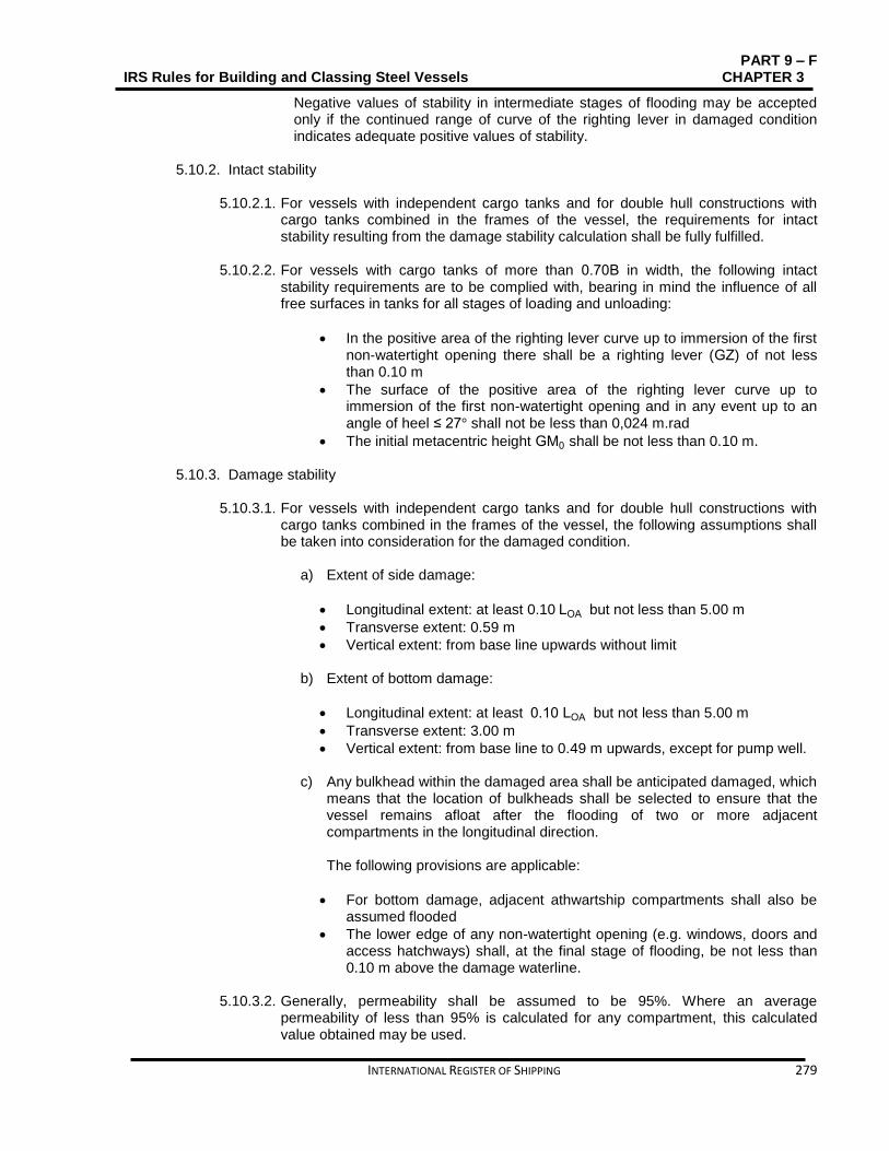
PART 9 – F IRS Rules for Building and Classing Steel Vessels CHAPTER 3
INTERNATIONAL REGISTER OF SHIPPING 279
Negative values of stability in intermediate stages of flooding may be accepted only if the continued range of curve of the righting lever in damaged condition indicates adequate positive values of stability.
5.10.2. Intact stability
5.10.2.1. For vessels with independent cargo tanks and for double hull constructions with
cargo tanks combined in the frames of the vessel, the requirements for intact stability resulting from the damage stability calculation shall be fully fulfilled.
5.10.2.2. For vessels with cargo tanks of more than 0.70B in width, the following intact stability requirements are to be complied with, bearing in mind the influence of all free surfaces in tanks for all stages of loading and unloading:
In the positive area of the righting lever curve up to immersion of the first non-watertight opening there shall be a righting lever (GZ) of not less than 0.10 m
The surface of the positive area of the righting lever curve up to immersion of the first non-watertight opening and in any event up to an angle of heel ≤ 27° shall not be less than 0,024 m.rad
The initial metacentric height GM0 shall be not less than 0.10 m. 5.10.3. Damage stability
5.10.3.1. For vessels with independent cargo tanks and for double hull constructions with cargo tanks combined in the frames of the vessel, the following assumptions shall be taken into consideration for the damaged condition.
a) Extent of side damage:
Longitudinal extent: at least 0.10 LOA but not less than 5.00 m
Transverse extent: 0.59 m
Vertical extent: from base line upwards without limit
b) Extent of bottom damage:
Longitudinal extent: at least 0.10 LOA but not less than 5.00 m
Transverse extent: 3.00 m
Vertical extent: from base line to 0.49 m upwards, except for pump well.
c) Any bulkhead within the damaged area shall be anticipated damaged, which means that the location of bulkheads shall be selected to ensure that the vessel remains afloat after the flooding of two or more adjacent compartments in the longitudinal direction.
The following provisions are applicable:
For bottom damage, adjacent athwartship compartments shall also be assumed flooded
The lower edge of any non-watertight opening (e.g. windows, doors and access hatchways) shall, at the final stage of flooding, be not less than 0.10 m above the damage waterline.
5.10.3.2. Generally, permeability shall be assumed to be 95%. Where an average
permeability of less than 95% is calculated for any compartment, this calculated value obtained may be used.
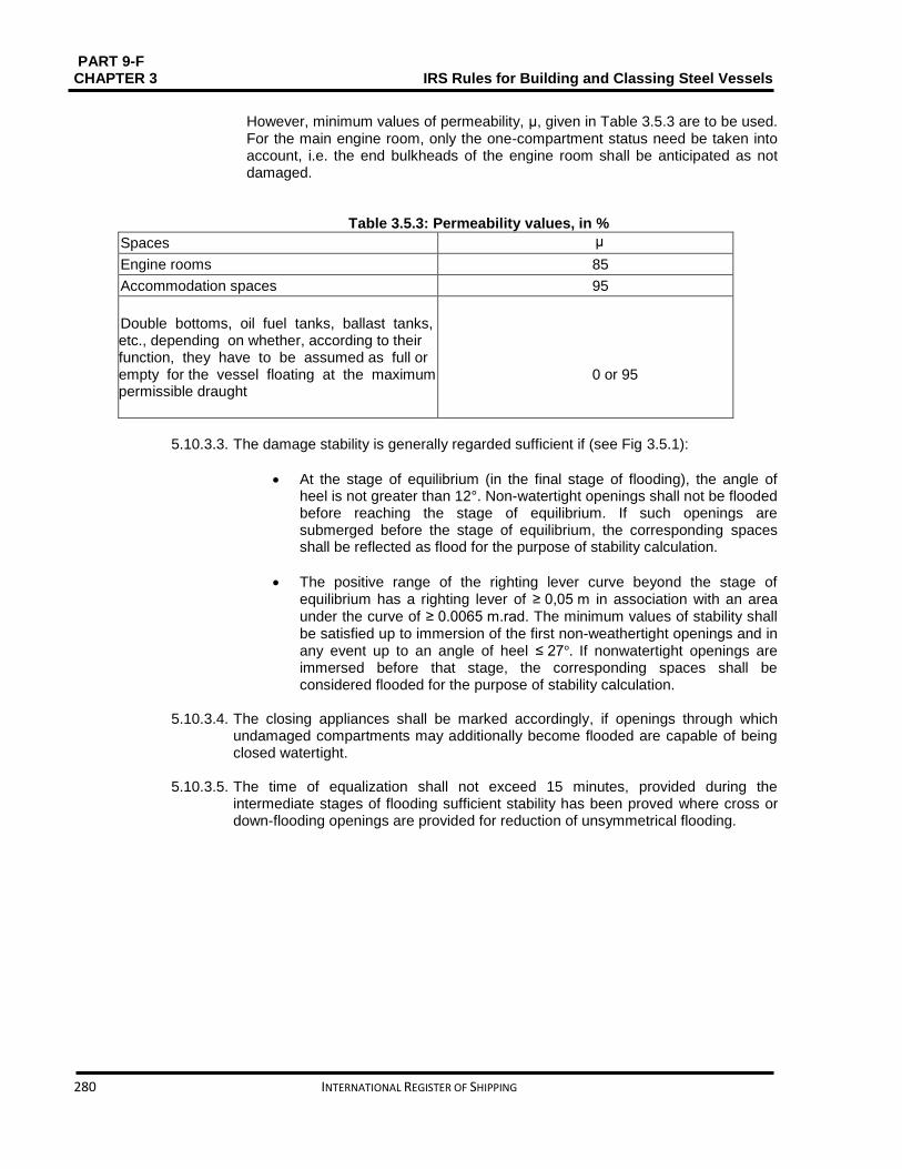
PART 9-F CHAPTER 3 IRS Rules for Building and Classing Steel Vessels
280 INTERNATIONAL REGISTER OF SHIPPING
However, minimum values of permeability, μ, given in Table 3.5.3 are to be used. For the main engine room, only the one-compartment status need be taken into account, i.e. the end bulkheads of the engine room shall be anticipated as not damaged.
Table 3.5.3: Permeability values, in %
Spaces μ
Engine rooms 85
Accommodation spaces 95
Double bottoms, oil fuel tanks, ballast tanks, etc., depending on whether, according to their function, they have to be assumed as full or empty for the vessel floating at the maximum permissible draught
0 or 95
5.10.3.3. The damage stability is generally regarded sufficient if (see Fig 3.5.1):
At the stage of equilibrium (in the final stage of flooding), the angle of heel is not greater than 12°. Non-watertight openings shall not be flooded before reaching the stage of equilibrium. If such openings are submerged before the stage of equilibrium, the corresponding spaces shall be reflected as flood for the purpose of stability calculation.
The positive range of the righting lever curve beyond the stage of equilibrium has a righting lever of ≥ 0,05 m in association with an area under the curve of ≥ 0.0065 m.rad. The minimum values of stability shall be satisfied up to immersion of the first non-weathertight openings and in any event up to an angle of heel ≤ 27°. If nonwatertight openings are immersed before that stage, the corresponding spaces shall be considered flooded for the purpose of stability calculation.
5.10.3.4. The closing appliances shall be marked accordingly, if openings through which
undamaged compartments may additionally become flooded are capable of being closed watertight.
5.10.3.5. The time of equalization shall not exceed 15 minutes, provided during the
intermediate stages of flooding sufficient stability has been proved where cross or down-flooding openings are provided for reduction of unsymmetrical flooding.

PART 9 – F IRS Rules for Building and Classing Steel Vessels CHAPTER 3
INTERNATIONAL REGISTER OF SHIPPING 281
Figure 3.5.1: Proof of damage stability

PART 9-F CHAPTER 3 IRS Rules for Building and Classing Steel Vessels
282 INTERNATIONAL REGISTER OF SHIPPING
SECTION 6 SUPPLY VESSEL Contents
6.1. General ........................................................................................................................................... 283
6.2. Vessel arrangement ....................................................................................................................... 283
6.3. Cargo containment ......................................................................................................................... 288
6.4. Cargo piping system ...................................................................................................................... 290
6.5. Cargo temperature control ............................................................................................................. 291
6.6. Receptacles for residual products and receptacles for slops ........................................................ 291
6.7. Electrical installations ..................................................................................................................... 292
6.8. Fire protection and fire extinction ................................................................................................... 295
6.9. Safety and control installations ...................................................................................................... 296
6.10. Buoyancy and stability ................................................................................................................... 296

PART 9 – F IRS Rules for Building and Classing Steel Vessels CHAPTER 3
INTERNATIONAL REGISTER OF SHIPPING 283
6.1. General
6.1.1. Symbols
L: Rule length, in m, defined in Part 9 C, Chapter 1, Sec 1, [1.2] LOA Length overall, in m, defined in Part 9 C, Chapter 1, Sec 1, [1.2]
B: Breadth, in m, defined in Part 9 C, Chapter 1, Sec 1, [1.2]
D: Depth, in m, defined in Part 9 C, Chapter 1, Sec 1, [1.2]
T: Draught, in m, defined in Part 9 C, Chapter 1, Sec 1, [1.2]
6.1.2. Application
Vessels complying with the requirements of this Section are eligible for the assignment of the additional service feature Type N open - Supply vessel as defined in Part A, Chapter 1, Sec 3, [3.2.14].
6.1.3. Documents to be submitted
Table 3.6.1 lists the plans and documents to be submitted in addition to the documents required in the other Parts of the Rules for the parts of the vessel not affected by the cargo, as applicable.
6.2. Vessel arrangement
6.2.1. Engine rooms
6.2.1.1. Internal combustion engines for the vessel’s propulsion as well as internal combustion engines for auxiliary machinery shall be located outside the cargo area. Entrances and other openings of engine rooms shall be at a distance of not less than 2.00 m from the cargo area.
6.2.1.2. The engine rooms shall be accessible from the deck; the entrances shall not face
the cargo area. When the doors are not located in a recess whose depth is at least equal to the door width, the hinges shall face the cargo area.
6.2.2. Accommodation and service spaces
6.2.2.1. Accommodation spaces and the wheelhouse shall be situated outside the cargo
area forward of the fore vertical plane or abaft the aft vertical plane bounding the part of cargo area below deck. Windows of the wheelhouse which are positioned not less than 1.00 m above the floor of the wheelhouse may tilt forward.
6.2.2.2. Entrances to spaces and openings of superstructures shall not face the cargo
area. 6.2.2.3. Entrances from the deck and openings of spaces facing the weather shall be
capable of being closed.
6.2.2.4. Machinery
a) Driving shafts of the bilge or ballast pumps in the cargo area may enter through the bulkhead between the service space and the engine room, provided the arrangement of the service space is in compliance with [6.2.3.6].
b) The Society shall approve the penetration of the shaft through the bulkhead which must be gastight.

PART 9-F CHAPTER 3 IRS Rules for Building and Classing Steel Vessels
284 INTERNATIONAL REGISTER OF SHIPPING
c) The necessary operating instructions shall be displayed.
d) Penetrations through the bulkhead between the engine room and the service space in the cargo area, and the bulkhead between the engine room and the hold spaces may be provided for electrical cables, hydraulic and piping for measuring, control and alarm systems, on condition that the penetrations have been permitted by the Society. The penetrations shall be gastight. Penetrations through a bulkhead with “A-60” fire protection insulation, shall have an equivalent fire protection.
e) Pipes may enter the bulkhead between the engine room and the service space in the cargo area provided that these are pipes between the mechanical equipment in the engine room and the service space which do not have any openings within the service space and which are provided with shut-off devices at the bulkhead in the engine room.
f) Notwithstanding [6.2.3.4], pipes from the engine room may enter the service space in the cargo area or a cofferdam or a hold space or a double-hull space to the outside provided that within the service space or cofferdam or hold space or doublehull space they are of the thick-walled type and have no flanges or openings.
6.2.3. Hold spaces
6.2.3.1. The cargo tanks shall be separated by cofferdams of at least 0.60 m in width from the accommodation, engine room and service spaces outside the cargo area below deck or, when there are no such accommodation, engine room and service spaces, from the vessel’s ends. A space of not less than 0.50 m shall be provided between such tanks and the end bulkheads of the hold space where the cargo tanks are installed in a hold space. In this case an end bulkhead meeting at least the definition for Class “A-60”, shall be considered equivalent to a cofferdam. For pressure cargo tanks, the 0.50 m distance may be reduced to 0.20 m.
Table 3.6.1: Documents to be submitted
No A/I Document
1 I Design characteristics of products to be carried, including maximum vapour pressure, maximum liquid cargo tem- perature and other important design conditions
2 I General arrangement plan, showing location of cargo tanks and fuel oil, ballast and other tanks, void spaces
3 A Ventilation duct arrangement in gas-dangerous spaces and adjacent zones
4 A Details of hull structure in way of cargo tanks, including support arrangement for tanks, saddles, anti-floating and anti-lifting devices, deck sealing arrangements, independent cargo tanks, etc. 5 A Intact and damage stability calculations
6 A Scantlings, material and arrangement of the cargo containment system
7 A Details of cargo handling system, including arrangements and details of piping and fittings
8 A Details of cargo pumps
9 A Bilge and ballast system in cargo area
10 A Gas freeing system in cargo tanks
11 A Ventilation system in cargo area
12 A Details of electrical equipment installed in cargo area, including the list of certified safe equipment and apparatus and electrical bonding of cargo tanks and piping
13 A Schematic electrical wiring diagram
14 A Gas detection system
15 A Cargo tank instrumentation

PART 9 – F IRS Rules for Building and Classing Steel Vessels CHAPTER 3
INTERNATIONAL REGISTER OF SHIPPING 285
16 A Details of fire-extinguishing appliances and systems in cargo area
17 A Arrangement drawing of the various fire bulkheads and decks with standard fire test reports for the various arrange- ments, surface coverings, paints and similar
18 I Loading and unloading operation description, including cargo tank filling limits, where applicable
19 I Loading and unloading operation description, including cargo tank filling limits, where applicable
20 A Gas return system
Note 1: A = to be submitted for review/approval in triplicate I = to be submitted for information in duplicate
6.2.3.2. Hold spaces, cofferdams and cargo tanks shall be capable of being inspected. 6.2.3.3. All spaces in the cargo area shall be well ventilated. Means for checking their gas-
free condition shall be provided. 6.2.3.4. The bulkheads bounding the cargo tanks, cofferdams and hold spaces shall be
watertight. The cargo tanks and the bulkheads bounding the cargo area shall have no openings or penetrations below deck.
The bulkhead between the engine room and the cofferdam or service space in the cargo area or between the engine room and a hold space may be fixed with penetrations provided that they conform to the provisions of [6.2.2.4].
The bulkheads between the cargo tanks may be fixed with penetrations on condition that the loading and unloading pipes are fixed with shut-off devices in the cargo tank from which they come. The shut-off devices shall be operable from the deck. These pipes shall be at least 0.60 m above the bottom.
6.2.3.5. Double hull spaces and double bottoms in the cargo area shall be prepared for being filled with ballast water only. Double bottoms may, however, be used as fuel oil tanks, provided they comply with [6.2.6].
6.2.3.6.
a. A cofferdam, the centre part of a cofferdam or another space below deck in the cargo area may be prepared as a service space, on condition that the bulkheads bounding the service space spread out vertically to the bottom. This service space shall only be accessible from the deck.
b. The service space shall be watertight with the exception of its access hatches and ventilation inlets.
6.2.3.7. The service spaces shall be arranged so as to be easily accessible and to permit
persons wearing protective clothing and breathing apparatus to safely operate the service equipment contained therein where service spaces are positioned in the cargo area under deck. They shall be planned so as to allow injured or unconscious personnel to be removed from such spaces without difficulty, if necessary by means fixed equipment.
Note 1:
A = to be submitted for review/approval in triplicate
I = to be submitted for information in duplicate

PART 9-F CHAPTER 3 IRS Rules for Building and Classing Steel Vessels
286 INTERNATIONAL REGISTER OF SHIPPING
6.2.3.8. Cofferdams, double-hull spaces, double bottoms, cargo tanks, hold spaces and
other accessible spaces within the cargo area shall be arranged so that they may be completely inspected and cleaned in an appropriate manner.
The dimensions of openings except for those of double-hull spaces and double bottoms which do not have a wall adjoining the cargo tanks shall be sufficient to allow a person wearing breathing apparatus to enter or leave the space without
difficulties. These openings shall have a minimum cross-sectional area of 0.36 𝑚2 and a minimum side length of 0.50 m. They shall be designed so as to allow an injured or unconscious person to be removed from the bottom of such a space without difficulties, if necessary by means of fixed equipment. In these spaces the distance between the reinforcements shall not be less than 0.50 m. In double bottoms this distance may be reduced to 0.45 m. Cargo tanks may have circular openings with a diameter of not less than 0.68 m.
6.2.4. Ventilation
6.2.4.1. Each hold space shall have two openings the dimensions and location of which
shall be such as to allow effective ventilation of any part of the hold space. If there are no such openings, it shall be possible to fill the hold spaces with inert gas or dry air.
6.2.4.2. Double-hull spaces and double bottoms within the cargo area which are not
arranged for being filled with ballast water, hold spaces and cofferdams, shall be arranged for ventilation systems.
6.2.4.3. Any service spaces located in the cargo area below deck shall be provided with a
system of forced ventilation with sufficient power for ensuring at least 20 changes of air per hour based on the volume of the space. The ventilation exhaust ducts shall be located up to 50 mm above the bottom of the service space. The fresh air inlets shall be located in the upper part; they shall be not less than 2.00 m above the deck, not less than 2.00 m from the openings of the cargo tanks and not less than 6.00 m from the outlets of safety valves.
The extension pipes which may be necessary may be of the hinged type.
On board open type N vessels other suitable installations without ventilator fans shall be sufficient.
6.2.4.4. Ventilation of accommodation and service spaces shall be possible.
6.2.5. Engines
6.2.5.1. Only internal combustion engines running on fuel with a flashpoint of more than 55
°C are allowed. 6.2.5.2. Ventilation inlets of the engine room and, when the engines do not take in air
directly from the engine room, the air intakes of the engines shall be placed not less than 2.00 m from the cargo area.
6.2.5.3. Sparking shall not be possible within the cargo area. 6.2.5.4. The surface temperature of the outer parts of engines used during loading or
unloading operations, as well as that of their air inlets and exhaust ducts shall not go beyond the allowable temperature according to the temperature class of the

PART 9 – F IRS Rules for Building and Classing Steel Vessels CHAPTER 3
INTERNATIONAL REGISTER OF SHIPPING 287
substances carried. This provision does not apply to engines installed in service spaces on condition that the provisions of [6.7.3.2] are fully complied with.
6.2.5.5. The ventilation in the closed engine room shall be projected so that, at an ambient
temperature of 20°C, the average temperature in the engine room does not go beyond 40 °C.
6.2.6. Oil fuel tanks
6.2.6.1. The double bottoms within these spaces may be arranged as oil fuel tanks,
provided their depth is not less than 0.60 m when the vessel is provided with hold spaces. Oil fuel pipes and openings of such tanks are not allowed in hold space.
6.2.6.2. The open ends of the air pipes of all oil fuel tanks shall outspread to not less than 0.50 m above the open deck. Their open ends and the open ends of overflow pipes leading on the deck shall be fixed with a protective device containing of a gauze diaphragm or a punctured plate.
6.2.7. Exhaust pipes
6.2.7.1. Exhausts shall be expatriated from the vessel into the open air either upwards through an exhaust pipe or through the shell plating. The exhaust outlet shall be located not less than 2.00 m from the cargo area. The exhaust pipes of engines shall be prepared so that the exhausts are led away from the vessel. The exhaust pipes shall not be placed within the cargo area.
6.2.7.2. Exhaust pipes shall be provided with a device preventing the escape of sparks,
e.g. spark arresters.
6.2.8. Bilge pumping and ballasting arrangements
6.2.8.1. Bilge and ballast pumps for spaces within the cargo area shall be installed within such area. This provision does not apply to:
Double-hull spaces and double bottoms which do not have a common boundary wall with the cargo tanks;
Cofferdams, double hull spaces, double bottoms and hold spaces where ballasting is carried out using the piping of the firefighting system in the cargo area and bilge-pumping is performed using eductors.
6.2.8.2. Double bottom shall not be connected to the bilge piping system, where it is used
as oil fuel tank. 6.2.8.3. The standpipe and its outboard connection for suction of ballast water shall be
located within the cargo area but outside the cargo tanks, where the ballast pump is installed in the cargo area.
6.2.8.4. A cargo pump-room below deck shall be capable of being drained in an
emergency by an installation located in the cargo area and independent from any other installation. This installation shall be done outside the cargo pump room.
6.2.9. Ventilation of cargo pump rooms
6.2.9.1. Cargo pump rooms must be equipped with extraction type ventilation systems, independent of other vessel's spaces, providing at least 30 cycles of air change

PART 9-F CHAPTER 3 IRS Rules for Building and Classing Steel Vessels
288 INTERNATIONAL REGISTER OF SHIPPING
per hour. Warning notices shall be placed needing that the ventilation is in operation for at least 15 minutes prior to entering these spaces.
6.2.9.2. Portable means must be provided for gas-freeing of cargo tanks and other spaces
not equipped with fixed ventilation.
6.2.10. Arrangements of cofferdams
6.2.10.1. Cofferdams or cofferdam compartments remaining once a service space has been arranged in accordance with [6.2.3.6] shall be accessible through an access hatch. If, on the other hand, the cofferdam is connected to a double-hull space, it is sufficient for it to be accessible from that space.
6.2.10.2. No fixed pipe shall permit connection between a cofferdam and other piping of the
vessel outside the cargo area. 6.3. Cargo containment
6.3.1. General
The scantlings and structural arrangements are to be in compliance with applicable requirements of Chapter 1, Sec 3.
6.3.2. Cargo area hull design
6.3.2.1. The space between the wall of the vessel and wall of the cargo tanks shall be not
less than 0.60 m, where independent cargo tanks are used, or for double- hull construction where the cargo tanks are integrated in vessel’s structure. The space between the bottom of the vessel and the bottom of the cargo tanks shall be not less than 0.50 m. The spaces may be reduced to 0.40 m under the pump sumps. The vertical space between the suction well of a cargo tank and the bottom structures shall be not less than m. The space between the bottom of the vessel and the bottom of the cargo tanks shall be not less than 0.50 m. The space may be reduced to 0.40 m under the pump sumps. The vertical space between the suction well of a cargo tank and the bottom structures shall be not less than 0.10 m. The above values are appropriate to the double hull, when a hull is constructed in the cargo area as a double hull with independent cargo tanks located in hold spaces. If in this case the minimum values for examinations of independent tanks referred to in [6.2.3.8] are not practicable, it must be possible to remove the cargo tanks easily for inspection.
6.3.2.2. Where service spaces are located in the cargo area under deck, they shall be arranged so as to be easily accessible and to permit persons wearing protective clothing and breathing apparatus to safely operate the service equipment contained therein. They shall be designed so as to allow injured or unconscious personnel to be removed from such spaces without difficulties, if necessary by means of fixed equipment.
6.3.2.3. Side stringers joining or supporting the load bearing components of the sides of
the vessel with the load bearing components of the longitudinal walls of cargo tanks and side stringers linking the load bearing components of the vessel’s bottom with the tank bottom are prohibited.

PART 9 – F IRS Rules for Building and Classing Steel Vessels CHAPTER 3
INTERNATIONAL REGISTER OF SHIPPING 289
6.3.3. Cargo tank sizes
6.3.3.1. The maximum permissible capacity of a cargo tank for single hull tank vessels, double hull tank vessels and vessels with tanks independent of the hull shall be determined in accordance with Table 3.6.2.
where: LOAB D: Product of the tank vessel main dimensions, in m3
LOA ∶ overall length of the hull, in m In the case of trunk deck vessels, D’ is to be
substituted for D. D’ is to be determined by the following formula:
D'= D + h
btlt
BLOA
where: ht: Height, in m, of trunk (distance between trunk deck and main deck on trunk side measured at LOA/2)
bt: Trunk breadth, in ml
lt: Trunk length, in m
6.3.3.2. Alternative constructions in compliance with Chapter 3, *** are permitted.
Table 3.6.2: Tank sizes
LOA B D in m3
Maximum permissible capacity of cargo tank, in m
<600 0.3LOA B D
From 600 to 3750 180+(LOA B D – 600) 0.0635
>3750 380
6.3.4. Cargo tank arrangements
6.3.4.1. The cargo tank is to comply with the following:
for vessels with a length not more than 50,00 m, the length of a cargo tank shall not exceed 10,00 m
for vessels with a length of more than 50,00 m, the length of a cargo tank shall not exceed 0,20 L, where L is the vessel rule length. This provision does not apply to vessels with independent built-in cylindrical tanks having a length to diameter ratio ≤ 7.
6.3.4.2. The capacity of a suction well shall be limited to not more than 0.1 m3.
6.3.5. Integrated tank scantlings
The scantlings of the integrated tank structure are to be determined in compliance with Chapter 1, Sec 3.
6.3.6. Independent cargo tank scantlings
6.3.6.1. Cargo tank scantlings
The scantlings of independent cargo tanks are to be determined in compliance with Chapter 1, Sec 3, [5.1.2].
6.3.6.2. Supports and fastenings
The scantlings of the tank supports and fastenings are to be in compliance with Chapter 1, Sec 3, [8].

PART 9-F CHAPTER 3 IRS Rules for Building and Classing Steel Vessels
290 INTERNATIONAL REGISTER OF SHIPPING
6.3.7. Cargo tank openings
6.3.7.1.
a) Cargo tank openings shall be located on deck in the cargo area. b) Cargo tank openings with a cross-section of more than 0.10 m2 and openings of
safety devices for preventing overpressures shall be located not less than 0.50 m above deck.
6.3.7.2. Safety devices
Each cargo tank or group of cargo tanks connected to a common vapour pipe shall be fitted with safety devices designed to prevent any accumulation of water and its penetration into the cargo tanks.
6.4. Cargo piping system
6.4.1. Arrangement for cargo pumps
Cargo pumps shall be capable of being shut down from the cargo area and from a position outside the cargo area.
6.4.2. Arrangement of cargo piping
6.4.2.1. Pipes for loading and unloading shall be independent of any other piping of the
vessel. 6.4.2.2. The pipes for loading and unloading shall be arranged so that, after loading or
unloading operations, the liquid remaining in these pipes may be safely removed and may flow either into the vessel’s tanks or the tanks ashore.
6.4.2.3. Piping for loading and unloading shall be clearly distinguishable from other piping,
e.g. by means of colour marking. 6.4.2.4. The shore connections shall be located not less than 6 m from the entrances to or
openings of, the accommodation and service spaces outside the cargo area. 6.4.2.5. Each shore connection of the vapour pipe and shore connections of the pipes for
loading and unloading, through which the loading or unloading operation is carried out, shall be fitted with a shut-off device.
6.4.3. Control and monitoring
6.4.3.1. Stop valves
The stop valves or other shut-off devices of the pipes for loading and unloading shall indicate whether they are open or shut.
6.4.4. Supply of cargo tanks with washing or ballast water
6.4.4.1. The suctions of these pipes shall be positioned within the cargo area but outside
the cargo tanks when pipes for loading and unloading are used for supplying the cargo tanks with washing or ballast water. Pumps for tank washing systems with related connections may be located outside the cargo area, provided the discharge side of the system is arranged in such a way that suction is not possible through

PART 9 – F IRS Rules for Building and Classing Steel Vessels CHAPTER 3
INTERNATIONAL REGISTER OF SHIPPING 291
that part. A spring-loaded non-return valve shall be attached to prevent any gases from being expelled from the cargo area through the tank washing system.
6.4.4.1. A non-return valve shall be fixed at the junction between the water suction pipe
and the cargo loading pipe.
6.4.5. Permissible loading and unloading flows
6.4.5.1. The permissible loading and unloading flows shall be calculated. For open type N with flame-arrester and open type N the loading and unloading flows depend on the total cross-section of the exhaust ducts.
6.4.5.2. Calculations concern the permissible maximum loading and unloading flow for
each cargo tank or each group of cargo tanks, taking into account the design of the ventilation system. These calculations shall take into consideration the fact that in the event of an unforeseen cut-off of the gas return piping or the compensation piping of the shore facility, the safety devices of the cargo tanks will prevent pressure in the cargo tanks from exceeding the following values:
over-pressure: 115% of the opening pressure of the high-velocity vent valve;
vacuum pressure: not more than the construction vacuum pressure but not exceeding 5 kPa
6.5. Cargo temperature control
6.5.1. Cargo tank heating
Cargo tank heating system is to be fitted as a distinct system, equipped with a heat exchanger positioned in the cargo area. Where special heat transfer media are used this requirement may be distributed with upon approval by the Society.
6.5.2. Boilers which are used for heating the cargo shall be fuelled with a liquid fuel having a flashpoint of more than 55°C. They shall be placed either in the engine room or in another separate space below deck and outside the cargo area, which is accessible from the deck or from the engine room.
6.5.3. The cargo heating system shall be planned so that the cargo cannot penetrate into the
boiler in the case of a leak in the heating coils. A cargo heating system with artificial draught shall be burned electrically.
6.5.4. The ventilation system of the engine room shall be designed taking into account the air
required for boiler.
6.6. Receptacles for residual products and receptacles for slops
6.6.1. General
6.6.1.1. If vessels are provided with a tank for residual products, it shall comply with the provisions of [6.1.3] and [6.1.4]. Receptacles for residual products and receptacles for slops shall be placed only in the cargo area. During filling of receptacles for residual products, means for collecting any leakage shall be placed under the filling connections.
6.6.1.2. Receptacles for slops shall be fire resistant and shall be capable of being closed
with lids. The receptacles for slops shall be marked and easy to handle.

PART 9-F CHAPTER 3 IRS Rules for Building and Classing Steel Vessels
292 INTERNATIONAL REGISTER OF SHIPPING
6.6.1.3. The maximum capacity of a tank for residual products is 30 m3.
6.6.1.4. The tank for residual products shall be equipped with:
A device for ensuring pressure equilibrium
An ullage opening
Connections, with stop valves, for pipes and hoses.
6.6.1.5. Receptacles for residual products shall be equipped with:
A connection enabling gases released during filling to be evacuated safely
A possibility of indicating the degree of filling
Connections with shut-off devices, for pipes and hoses.
6.6.1.6. Receptacles for residual products placed on the deck shall be located at a minimum distance from the hull equal to one quarter of the vessel’s breadth.
6.7. Electrical installations
6.7.1. Documents to be kept on board
Additionally to the documents required in accordance with the Regulations referred to in Part 9E Chapter 1 Section 1, [1.2] and Section 4 the following documents shall be on board:
a) A drawing clearly indicating the boundaries of the cargo area and the location of the
electrical equipment set up in this area
b) A list of the electrical equipment referred to in (a) above including the following particulars: machine or appliance, location, type of protection, type of protection against explosion, testing body and approval number
c) A list of or general plan indicating the electrical equipment outside the cargo area
which may be operated during loading, unloading or gas-freeing. All other electrical equipment shall be marked in red.
6.7.2. General design requirements
6.7.2.1. Only distribution systems without return connection to the hull are allowed. This provision does not apply to:
Certain limited sections of the installations situated outside the cargo area (connections of starters of diesel engines)
Device for checking the insulation level referred to in [6.7.2.2]
Active cathodic corrosion protection.
6.7.2.2. Every insulated distribution network shall be fixed with an automatic device with a visual and audible alarm for checking the insulation level.
6.7.2.3. For the selection of electrical equipment to be used in zones presenting an
explosion risk, the explosion groups and temperature classes allocated to the substances carried shall be taken into consideration.
6.7.3. Type and location of electrical equipment
6.7.3.1. a) Only measuring, regulation and alarm devices of the EEx (ia) type of protection
may be set up in cargo tanks, residual cargo tanks and pipes for loading and unloading (comparable to zone 0)

PART 9 – F IRS Rules for Building and Classing Steel Vessels CHAPTER 3
INTERNATIONAL REGISTER OF SHIPPING 293
b) Only the following equipment may be fixed in the cofferdams, double-hull spaces,
double bottoms and hold spaces (comparable to zone 1):
Measuring, regulation and alarm devices of the certified safe type
Lighting appliances of the “flame-proof enclosure” or “pressurised enclosure” type of protection
Hermetically sealed echo sounding devices the cables of which are led through thick-walled steel
Tubes with gastight connections up to the main deck
Cables for the active cathodic protection of the shell plating in protective steel tubes such as those provided for echo sounding devices
c) Only the following equipment may be set up in the service spaces in the cargo area
below deck (comparable to zone 1):
Measuring, regulation and alarm devices of the certified safe type
Lighting appliances of the “flame-proof enclosure” or “apparatus protected by pressurization” type of protection
Motors driving essential equipment such as ballast pumps; they shall be of the certified safe type
d) The control and protective equipment of the electrical equipment referred to in
paragraphs (a), (b) and (c) above shall be located outside the cargo area if they are not intrinsically safe
e) The electrical equipment in the cargo area on deck (comparable to zone 1) shall be
of the certified safe type. 6.7.3.2.
a) Electrical equipment used during loading, unloading and gas-freeing during
berthing and which are located outside the cargo area shall (comparable to zone 2) be at least of the “limited explosion risk” type.
b) This provision does not apply to:
Lighting installations in the accommodation, except for switches near entrances to accommodation
Radiotelephone installations in the accommodation or the wheelhouse
Electrical installations in the accommodation, the wheelhouse or the service spaces outside the cargo areas if:
These spaces are fitted with a ventilation system ensuring an overpressure of 0,1 kPa (0,001 bar) and none of the windows is capable of being opened; the air intakes of the ventilation system shall be located as far away as possible, however, not less than 6,00 m from the cargo area and not less than 2,00 m above the deck
The spaces are fitted with a gas detection system with sensors:
- At the suction inlets of the ventilation system - Directly at the top edge of the sill of the entrance doors of the
accommodation and service spaces
The gas concentration measurement is continuous
The ventilators are switched off when the gas concentration reaches 20% of the lower explosive limit. In such a case and when the overpressure is not

PART 9-F CHAPTER 3 IRS Rules for Building and Classing Steel Vessels
294 INTERNATIONAL REGISTER OF SHIPPING
sustained or in the event of failure of the gas detection system, the electrical installations which do not fulfill (a) above, shall be switched off. These operations shall be carried out immediately and automatically and activate the emergency lighting in the accommodation, the wheelhouse and the service spaces, which shall fulfill at least with the “limited explosion risk” type. The switching-off shall be indicated in the accommodation and wheelhouse by visual and audible signals
The ventilation system, the gas detection system and the alarm of the switch-off device fully comply with the requirements of (a) above
The automatic switching-off device is set so that no automatic switch off may occur while the vessel is under way.
6.7.3.3. The electrical equipment which does not meet the requirements depart in [6.7.3.2]
together with its switches shall be marked in red. The disconnection of such equipment shall be operated from a centralised location on board.
6.7.3.4. A permanent electric engine generator which does not meet the requirements of
[6.7.3.2], shall be fixed with a switch capable of shutting down the excitation of the generator. A notice board with the operating instructions shall be shown near the switch.
6.7.3.5. Sockets for the connection of signal lights and gangway lighting shall be
permanently fixed to the vessel close to the signal mast or the gangway. Connecting and disconnecting shall not be possible except when the sockets are not live.
6.7.3.6. The failure of the power supply for the safety and control equipment shall be
instantly specified by visual and audible signals at the locations where the alarms are generally actuated.
6.7.4. Earthing
6.7.4.1. The metal parts of electrical appliances in the cargo area which are not live as well as protective metal tubes or metal sheaths of cables in normal service shall be earthed, unless they are so arranged that they are automatically earthed by bonding to the metal structure of the vessel.
6.7.4.2. The provisions of [6.7.4.1] above apply also to equipment having service voltages
of less than 50 V.
6.7.4.3. Independent cargo tanks, metal intermediate bulk containers and tank-containers shall be earthed.
6.7.4.4. Receptacles for residual products shall be capable of being earthed.
6.7.5. Electrical cables
6.7.5.1. All cables in the cargo area shall have a metallic sheath.
6.7.5.2. Cables and sockets in the cargo area shall be protected against mechanical damage.
6.7.5.3. Movable cables are prohibited in the cargo area, except for intrinsically safe
electric circuits or for the supply of signal lights, gangway lighting.

PART 9 – F IRS Rules for Building and Classing Steel Vessels CHAPTER 3
INTERNATIONAL REGISTER OF SHIPPING 295
6.7.5.4. Cables of intrinsically safe circuits shall only be used for such circuits and shall be separated from other cables not intended for being used in such circuits (e.g. they shall not be installed together in the same string of cables nor fixed by the same cable clamps).
6.7.5.5. In accordance with standard IEC 60 245-4:1994 or for movable cables intended
for signal lights, gangway lighting, only sheathed cables of type H 07 RN-F of at least equivalent design having conductors with a cross-section of not less than 1,5 mm² shall be used. These cables shall be as short as possible and installed so that damage is not likely to occur.
6.7.6. Storage batteries
Storage batteries shall be located outside the cargo area.
6.8. Fire protection and fire extinction
6.8.1. Fire and naked light
6.8.1.1. The outlets of funnels shall be located not less than 2.00 m from the cargo area. Arrangements shall be provided to prevent the escape of sparks and the entry of water.
6.8.1.2. Heating, cooking and refrigerating appliances shall not be fuelled with liquid fuels,
liquid gas or solid fuels. The installation in the engine room or in another separate space of heating appliances fuelled with liquid fuel having a flash-point above 55°C is, though, allowed. Cooking and refrigerating appliances are allowed only in the lodging space.
6.8.1.3. Only electrical lighting appliances are permitted.
6.8.2. Prohibition of smoking, fire or naked light
6.8.2.1. In accordance with ADN Regulations Section 8.3.4, the notice boards displaying
the prohibition of smoking shall be clearly legible from either side of the vessel. 6.8.2.2. Notice boards indicating the circumstances under which the prohibition is
applicable shall be fixed near the entrances to the spaces where smoking or the use of fire or naked light is not always prohibited.
6.8.3. Fire extinguishing arrangements
Additionally to the requirements of Part 9D, Chapter 15, the fire extinguishing arrangements in [6.8.4] to [6.8.6] are to be fulfilled.
6.8.4. Portable fire extinguishers
Additionally to the fire-extinguishing appliances prescribed in Part D the vessel shall be equipped with at least two additional portable fire-extinguishers having the same capacity in cargo area. These additional portable fire-extinguishers shall be appropriate for fighting fires involving the dangerous goods carried.
6.8.5. Fire extinguishing system
A fire-extinguishing system fulfilling the following requirements shall be installed on the vessel.

PART 9-F CHAPTER 3 IRS Rules for Building and Classing Steel Vessels
296 INTERNATIONAL REGISTER OF SHIPPING
It shall be supplied by two independent fire or ballast pumps, one of which shall be ready for use at any time. These pumps and their means of propulsion and electrical equipment shall not be installed in the same space
It shall be provided with a water main fitted with at least three hydrants in the cargo area above deck. Three suitable and sufficiently long hoses with spray nozzles having a diameter of not less than 12 mm shall be provided
It shall be possible to reach any point of the deck in the cargo area at the same time with at least two jets of water not supplied from the same hydrant A spring-loaded non-return valve shall be fixed to ensure that no gases can escape through the fire-extinguishing system into the lodging space or service spaces outside the cargo area.
The capacity of the system shall be at least sufficient for a jet of water to have a minimum reach of not less than the vessel's breadth from any location on board with two spray nozzles being used simultaneously.
6.8.6. Fixed fire extinguishing system
Additionally, the engine rooms, the pump room and all spaces containing essential equipment (switchboards, compressors, etc.) for the refrigeration equipment, if any, shall be provided with a permanently fixed fire-extinguishing system, in compliance with Part D.
6.9. Safety and control installations 6.9.1. General
Cargo tanks shall be provided with the following equipment:
a) A mark inside the tank indicating the liquid level of 97%
b) A high level sensor for actuating the facility against overflowing at the latest when a degree of filling of 97.5% is reached.
6.10. Buoyancy and stability
6.10.1. General
6.10.1.1. Exceptions to the requirements stated in these Rules are possible where they are permitted by the statutory Regulations.
6.10.1.2. General requirements of Part 9 C Chapter 8a are to be complied with. 6.10.1.3. The longitudinal centre bulkhead may be dispensed with only if sufficient stability is
guaranteed. 6.10.1.4. Proof of sufficient stability shall be furnished. This proof is not required for single
hull vessels with cargo tanks the width of which is not more than 0.70B. 6.10.1.5. The basic values for the stability calculation (the vessel’s lightweight and location of
the centre of gravity) shall be determined in compliance with Part 9C, Chapter 8,. 6.10.1.6. Proof of intact stability is to be provided for all loading/ unloading stages and for the
final loading condition.

PART 9 – F IRS Rules for Building and Classing Steel Vessels CHAPTER 3
INTERNATIONAL REGISTER OF SHIPPING 297
6.10.1.7. Floatability after damage shall be proved for the most undesirable loading condition. For this purpose, calculated proof of sufficient stability shall be established for critical intermediate stages of flooding and for the final stage of flooding. Negative values of stability in intermediate stages of flooding may be accepted only if the continued range of curve of the righting lever in damaged condition indicates adequate positive values of stability.
6.10.2. Intact stability
6.10.2.1. For vessels with independent cargo tanks and for double hull constructions with cargo tanks combined in the frames of the vessel, the requirements for intact stability resulting from the damage stability calculation shall be fully fulfilled.
For vessels with cargo tanks of more than 0,70B in width, the following intact stability requirements are to be fulfilled, bearing in mind the influence of all free surfaces in tanks for all stages of loading and unloading:
In the positive area of the righting lever curve up to immersion of the first non-watertight opening there shall be a righting lever (GZ) of not less than 0,10 m
The surface of the positive area of the righting lever curve up to immersion of the first non-watertight opening and in any event up to an angle of heel ≤27° shall not be less than 0,024 m.rad
The initial metacentric height GM0 shall be not less than 0,10 m.
6.10.3. Damage stability
6.10.3.1. For vessels with independent cargo tanks and for double hull constructions with cargo tanks combined in the frames of the vessel, the following assumptions shall be taken into consideration for the damaged condition.
a) Extent of side damage:
Longitudinal extent: at least 0,10 LOA but not less than 5,00 m
Transverse extent: 0,59 m
Vertical extent: from base line upwards without limit
b) Extent of bottom damage:
Longitudinal extent: at least 0,10 LOA but not less than 5,00 m
Transverse extent: 3,00 m
Vertical extent: from base line to 0,49 m upwards, except for pump well.
c) Any bulkhead within the damaged area shall be anticipated damaged,
which means that the location of bulkheads shall be selected to ensure that the vessel remains afloat after the flooding of two or more adjacent compartments in the longitudinal direction.
The following provisions are applicable:
For bottom damage, adjacent athwartship compartments shall also be assumed flooded

PART 9-F CHAPTER 3 IRS Rules for Building and Classing Steel Vessels
298 INTERNATIONAL REGISTER OF SHIPPING
The lower edge of any non-watertight opening (e.g. windows, doors and access hatchways) shall, at the final stage of flooding, be not less than 0,10 m above the damage waterline.
6.10.3.2. Generally, permeability shall be assumed to be 95%. Where an average
permeability of less than 95% is calculated for any compartment, this calculated value obtained may be used. However, minimum values of permeability, µ, given in Table 3.6.3 are to be used. For the main engine room, only the one-compartment status need be taken into account, i.e. the end bulkheads of the engine room shall be assumed as not damaged.
Table 3.6.3: Permeability values, in %
Spaces μ
Engine rooms 85
Accommodation spaces 95
Double bottoms, oil fuel tanks, ballast tanks, etc., depending on whether, according to their function, they have to be assumed as full or empty for the vessel floating at the maximum permissible draught
0 or 95
6.10.3.3. The damage stability is generally regarded sufficient if (see Fig 3.6.1):
At the stage of equilibrium (in the final stage of flooding), the angle of heel is not greater than 12°. Non-watertight openings shall not be flooded before reaching the stage of equilibrium. If such openings are submerged before the stage of equilibrium, the corresponding spaces shall be reflected flooded for the purpose of stability calculation.
The positive range of the righting lever curve beyond the stage of equilibrium has a righting lever of ≥0,05 m in association with an area under the curve of ≥0,0065 m.rad. The minimum values of stability shall be satisfied up to immersion of the first non-weathertight openings and in any event up to an angle of heel ≤27°. If nonwatertight openings are immersed before that stage, the corresponding spaces shall be considered flooded for the purpose of stability calculation.
6.10.3.4. The closing appliances shall be marked accordingly, if openings through which
undamaged compartments may additionally become flooded are capable of being closed watertight.
6.10.3.5. The time of equalization shall not exceed 15 minutes, provided during the
intermediate stages of flooding sufficient stability has been proved where cross- or down-flooding openings are provided for reduction of unsymmetrical flooding.

PART 9 – F IRS Rules for Building and Classing Steel Vessels CHAPTER 3
INTERNATIONAL REGISTER OF SHIPPING 299
Figure 3.6.1: Proof of damage stability

PART 9-F CHAPTER 3 IRS Rules for Building and Classing Steel Vessels
300 INTERNATIONAL REGISTER OF SHIPPING
SECTION 7 DG Contents
7.1. General ........................................................................................................................................... 301
7.2. Vessel arrangement ....................................................................................................................... 301
7.3. Cargo holds .................................................................................................................................... 303
7.4. Electrical installations ..................................................................................................................... 303
7.5. Fire protection and fire extinction ................................................................................................... 304
7.6. Additional rules applicable to double hull vessels .......................................................................... 305

PART 9 – F IRS Rules for Building and Classing Steel Vessels CHAPTER 3
INTERNATIONAL REGISTER OF SHIPPING 301
7.1. General
7.1.1. Symbols
LOA Length overall, in m, defined in Part 9C, Chapter 1, Sec 1, [1.2]
7.1.2. Application
7.1.2.1. The additional service feature DG is assigned, fulfilling Part A, Chapter 2, Sec 2, [2.3.2.3], to vessels planned to carry dry dangerous goods.
7.1.2.2. Vessels dealt with in this Section are to fulfill with the requirements stated under
Part A, Part B and Part C, as applicable, and with the requirements of this Section, which are specific to dry cargo vessels for the transport of dangerous goods.
7.1.3. Documents to be submitted
Table 3.7.1 lists the plans and documents to be submitted in addition to the documents required in the other Parts of the Rules for the parts of the vessel not affected by the cargo, as applicable.
7.2. Vessel arrangement
7.2.1. Accommodation and service spaces
7.2.1. The lodging space shall be separated from the holds by metal bulkheads having no openings.
7.2.2. Gastight closing appliances shall be provided for openings in the lodging space
and wheelhouse facing the holds.
7.2.3. No entrances or openings of the engine rooms and service spaces shall face the protected area.
7.2.2. Water ballast
The double-hull spaces and double bottoms may be prepared for being filled with water ballast.
7.2.3. Ventilation
7.2.3.1. Ventilation of each hold shall be provided by means of two mutually independent
withdrawal ventilators having a capacity of not less than five changes of air per hour based on the volume of the empty hold. The ventilator fan shall be designed in such way that no sparks may be emitted on contact of the impeller blades with the housing and no static electricity may be generated. The extraction ducts shall be located at the extreme ends of the hold and extend down to not more than 50 mm above the bottom. The extraction of gases and vapours through the duct shall also be confirmed for carriage in bulk. If the extraction ducts are movable, they shall be appropriate for the ventilator assembly and capable of being firmly fixed. Protection shall be confirmed against bad weather and spray. The air intake shall be ensured during ventilation.

PART 9-F CHAPTER 3 IRS Rules for Building and Classing Steel Vessels
302 INTERNATIONAL REGISTER OF SHIPPING
Table 3.7.1: Documents to be submitted
No A/I Document
1 I List of products to be carried, including maximum vapour pressure, maximum liquid cargo temperature and other important design conditions
2 I General arrangement plan, showing location of cargo holds and fuel oil, ballast and other tanks 3 A Location of void spaces and accesses to dangerous zones
4 A Details of hull structure in way of cargo holds
5 A Intact and damage stability calculations
6 A Bilge and ballast system in cargo area
7 A Ventilation system in cargo area
8 A Details of electrical equipment installed in cargo area
9 A Schematic electrical wiring diagram
10 A Details of fire-extinguishing appliances and systems in cargo area
Note 1: A = to be submitted for review/approval in triplicate I = to be submitted for information in duplicate
7.2.3.2. The ventilation system of a hold shall be prepared so that dangerous gases
cannot enter into the accommodation, wheelhouse or engine rooms.
7.2.3.3. Ventilation shall be provided for the accommodation and for service spaces.
7.2.4. Engines
7.2.4.1. Only internal combustion engines running on fuel with a flashpoint of more than 55 °C are allowed.
7.2.4.2. The air vents in the engine rooms and the air intakes of the engines which do not
take air in directly from the engine room shall be located not less than 2.00 m from the protected area.
7.2.4.3. Sparking shall not be possible within the cargo area.
7.2.5. Oil fuel tanks
7.2.5.1. Double bottoms within the hold area may be planned as oil fuel tanks
provided their depth is not less than 0.6 m. Oil fuel pipes and openings to such tanks are not allowed in the holds.
7.2.5.2. The air pipes of all oil fuel tanks shall be led to 0.50 m above the open deck.
Their open ends and the open ends of the overflow pipes leaking to the deck shall be fixed with a protective device containing of a gauze grid or by a perforated plate.
7.2.6. Exhaust pipes
7.2.7.1. Exhausts shall be emptied from the vessel into the open air either upwards
through an exhaust pipe or through the shell plating. The exhaust outlet shall be placed not less than 2.00 m from the hatchway openings. The exhaust pipes of engines shall be prepared so that the exhausts are led away from the vessel. The exhaust pipes shall not be positioned within the protected area.
7.2.7.2. Exhaust pipes shall be provided with a device preventing the escape of sparks,
e.g. spark arresters.
PART 9 – F IRS Rules for Building and Classing Steel Vessels CHAPTER 3
INTERNATIONAL REGISTER OF SHIPPING 303
7.3. Cargo holds
7.3.1. General arrangements
7.3.1.1. Each cargo hold shall be bounded fore and aft by watertight metal bulkheads. 7.3.1.2. The cargo holds shall have no common bulkhead with the fuel oil tanks. 7.3.1.3. The bottom of the holds shall be such as to permit them to be cleaned an dried. 7.3.1.4. Hatch covers for the cargo holds must be spraytight and weathertight. The use of
waterproof tarpaulins is also possible to cover the cargo holds, if the tarpaulin is not readily ignitable.
7.3.2. Heating installation
It is not allowed to arrange heating appliances in the cargo holds.
7.3.3. Stripping installation
The stripping pumps intended for the holds shall be located in the protected area. This requirement shall not apply when stripping is effected by eductors.
7.4. Electrical installations
7.4.1. Type and location of electrical equipment
7.4.1.1. It shall be possible to isolate the electrical equipment in the protected area by means of centrally located switches except where:
in the holds, it is of a certified safe type corresponding at least to temperature class T4 and explosion group II B and
in the protected area on deck, it is of the limited explosion risk type.
The corresponding electrical circuits shall have control lamps to indicate whether or not the circuits are live. The switches shall be protected against unintended unauthorized operation. The sockets used in this area shall be so designed as to prevent connections being made except when they are not live.
Submerged pumps installed or used in the holds shall be of the certified safe type at least for temperature class T4 and explosion group II B.
7.4.1.2. Electric motors for hold ventilators which are arranged in the air flow shall be of the
certified safe type. 7.4.1.3. Sockets for the connection of signal lights, gangway lighting and containers shall
be fitted to the vessel close to the signal mast or the gangway or the containers. Sockets intended to supply the submerged pumps and hold ventilators shall be permanently fitted to the vessel in the vicinity of the hatches.
7.4.2. Electric cables
7.4.2.1. Cables and sockets in the cargo area shall be protected against mechanical
damage.
PART 9-F CHAPTER 3 IRS Rules for Building and Classing Steel Vessels
304 INTERNATIONAL REGISTER OF SHIPPING
7.4.2.2. Movable cables are prohibited in the protected area, except for intrinsically safe
electric circuits or for the supply of signal lights and gangway lighting, for containers, for submerged pumps, hold ventilators and for electrically operated cover gantries.
7.4.2.3. For movable cables permitted in accordance with [7.4.2.2], only rubber-sheathed
cables of type H07 RN-F in accordance with standard IEC-60 245-4:1994 or cables of at least equivalent design having conductors with a cross-section of not less than 1.5 mm2, shall be used. These cables shall be as short as possible and installed so that accidental damage is not likely to occur.
7.4.3. Metal wires, masts
All metal wires passing over the holds and all masts shall be earthed, unless they are electrically bonded to the metal hull of the vessel through their installation.
7.4.4. Storage batteries
The installation of storage batteries inside the protected area is not permissible.
7.5. Fire protection and fire extinction
7.5.1. Fire and naked light 7.5.1.1. The outlets of funnels shall be located not less than 2.00 m from the cargo area.
Arrangements shall be provided to prevent the escape of sparks and the entry of water.
7.5.1.2. Heating, cooking and refrigerating appliances shall not be fuelled with liquid fuels,
liquid gas or solid fuels. The installation in the engine room or in another separate space of heating appliances fuelled with liquid fuel having a flash-point above 55°C is, however, permitted. Cooking and refrigerating appliances are permitted only in the accommodation.
7.5.1.3. Only electrical lighting appliances are permitted.
7.5.2. Prohibition of smoking, fire or naked light
7.5.2.1. The notice boards displaying the prohibition of smoking in accordance with 7.8.3.4
shall be clearly legible from either side of the vessel.
7.5.2.2. Notice boards indicating the circumstances under which the prohibition is applicable shall be fitted near the entrances to the spaces where smoking or the use of fire or naked light is not always prohibited.
7.5.3. Fire extinguishing arrangements
In addition to the requirements of Part 9D, Chapter 15, the fire extinguishing arrangements in [7.5.4] to [7.5.6] are to be complied with.
7.5.4. Portable fire extinguishers In addition to the fire-extinguishing appliances prescribed in Part 9D, Chapter 15, Sec 2, [2.4], the vessel shall be equipped with at least two additional portable fire-extinguishers having the same capacity in cargo area. These additional portable fire-extinguishers shall be suitable for fighting fires involving the dangerous goods carried.

PART 9 – F IRS Rules for Building and Classing Steel Vessels CHAPTER 3
INTERNATIONAL REGISTER OF SHIPPING 305
7.5.5. Water fire extinguishing system
A water fire-extinguishing system complying with the following requirements shall be installed on the vessel.
It shall be supplied by two independent fire or ballast pumps one of which shall be ready for use at any time. These pumps and their means of propulsion and electrical equipment shall not be installed in the same space
It shall be provided with a water main fitted with at least three hydrants in the cargo area above deck. Three suitable and sufficiently long hoses with spray/jet nozzles having a diameter of not less than 12 mm shall be provided
It shall be possible to reach any point of the deck in the cargo area simultaneously with at least two jets of water not supplied from the same hydrant
A spring-loaded non-return valve shall be fitted to ensure that no gases can escape through the fire-extinguishing system into the accommodation or service spaces outside the cargo area.
The capacity of the system shall be at least sufficient for a jet of water to have a minimum reach of not less than the vessel's breadth from any location on board with two spray nozzles being used at the same time.
7.5.6. Fixed fire extinguishing system
In addition the engine room, the pump room and all spaces containing essential equipment (switchboards, compressors, etc.) for the refrigeration equipment, if any, shall be provided with a fixed fire-extinguishing system, in compliance with Part 9D, Chapter 15, Sec 2, [2.6].
7.6. Additional rules applicable to double hull vessels
7.6.1. Application
The requirements of this Article are applicable to double hull vessels intended to carry dangerous goods in quantities exceeding those indicated in Paragraph 7.1.4.1.1 of ADN Regulations.
7.6.2. Holds
7.6.2.1. The vessel shall be built as a double-hull vessel with double-hull spaces and
double bottom within the protected area. 7.6.2.2. The distance between the sides of the vessel and the longitudinal bulkheads of the
cargo hold shall be not less than 0,80 m.
This distance may be reduced to a distance of 0.60 m if the following reinforcements of the hull structure are provided:
a) If the vessel's sides are constructed according to the longitudinal framing
system, the frame spacing shall not exceed 0.60 m and the longitudinal frames have to be supported by web frames with a maximum spacing of 1.80 m. These intervals may be increased if the construction is correspondingly reinforced.
b) If the vessel's sides are constructed according to the transverse framing
system either:

PART 9-F CHAPTER 3 IRS Rules for Building and Classing Steel Vessels
306 INTERNATIONAL REGISTER OF SHIPPING
two longitudinal side shell stringers shall be fitted; the distance between the two stringers and between the uppermost stringer and the gangboard shall not exceed 0.80 m; the depth of the stringers shall be at least equal to that of the transverse frames and the cross-section of the face plate shall be not less than 15 cm2. The longitudinal stringers shall be supported by web frames with lightening holes similar to plate floors in the double bottom and spaced 3.60 m apart. The transverse shell frames and the hold bulkhead vertical stiffeners shall be connected at the bilge by a bracket plate with height of not less than 0.90 m and thickness of the floors; or
web frames with lightning holes similar to the double bottom plate floors shall be arranged on each transverse frame.
c) The gangboards shall be supported by transverse bulkheads or cross ties
spaced not more than 32 m apart. Alternative arrangements will be considered by the Society on a case-by-case basis.
7.6.2.3. The depth of the double bottom shall be at least 0.50 m. The depth below the
suction wells may, however, be locally reduced, but the space between the bottom of the suction well and the bottom of the vessel floor shall be at least 0.40 m. If spaces are between 0.40 m and 0.49 m, the surface area of the suction well shall not exceed 0.5 m2. The capacity of the suction wells must not exceed 0.120 m3.
7.6.3. Emergency exit
Spaces not flooded of which the entrances or exits are partly or fully immersed in damage condition shall be provided with an emergency exit not less than 0.10 m above the damage waterline. This requirement does not apply to fore peak and aft peak.
7.6.4. Buoyancy and stability
7.6.4.1. General
Exceptions to the requirements stated in these Rules are possible where they are allowed only by the applicable statutory Regulations.
Proof of sufficient stability shall be furnished, as well as stability in the damaged condition.
General requirements of Part 9C, Chapter 8 are to be fulfilled.
Proof of sufficient intact stability shall be provided for all stages of loading and unloading and for the final loading condition.
7.6.4.2. Floatability after damage shall be proved for the most undesirable loading
condition. For this purpose, calculated proof of sufficient stability shall be established for critical intermediate stages of flooding and for the final stage of flooding. Negative values of stability in intermediate stages of flooding may be accepted only if the continued range of curve of the righting lever in damaged condition indicates adequate positive values stability.

PART 9 – F IRS Rules for Building and Classing Steel Vessels CHAPTER 3
INTERNATIONAL REGISTER OF SHIPPING 307
7.6.4.3. Intact stability The requirements for intact stability resulting from the damage stability calculation shall be fully fulfilled.In accordance with Chapter 2, Sec 5, [5.2] for the carriage of general cargoes and wheeled cargoes, proof of sufficient stability shall also be supplied. In accordance with Chapter 2, Sec 5, [5.3] for the carriage of dry bulk cargoes, proof of sufficient stability shall also be furnished For the carriage of containers, proof of sufficient stability shall also be furnished in accordance with Chapter 2, Sec 5, [5.4].
7.6.4.4. Damage stability - assumptions
The damage condition calculation is to be done on the basis of the following assumptions:
a) Extent of side damage:
Longitudinal extent: at least 0.10 LOA but not less than 5.00 m
Transverse extent: 0.59 m
Vertical extent: from base line upwards without limit
b) Extent of bottom damage:
Longitudinal extent: at least 0.10 LOA but not less than 5.00 m
Transverse extent: 3.00 m
Vertical extent: from base line to 0.49 m upwards, except for pump well.
d) Any bulkhead within the damaged area shall be anticipated damaged,
which means that the location of bulkheads shall be selected to ensure that the vessel remains afloat after the flooding of two or more adjacent compartments in the longitudinal direction. The following provisions applicable:
For bottom damage, adjacent athwartship compartments shall also be assumed as flooded.
The lower edge of any non-watertight opening (e.g. windows, doors and access hatchways) shall, at the final stage of flooding, be not less than 0.10 m above the damage waterline.
Generally, permeability shall be assumed to be 95%. This calculated value obtained may be used where an average permeability of less than 95% is calculated for any compartment,
However, minimum values of permeability, μ, given in Table 3.7.2 are to be used. For the main engine room, only the one-compartment status need be taken into account, i.e. the end bulkheads of the engine room shall be anticipated not damaged.

PART 9-F CHAPTER 3 IRS Rules for Building and Classing Steel Vessels
308 INTERNATIONAL REGISTER OF SHIPPING
Table 3.7.2: Permeability values, in %
Spaces μ
Engine rooms 85
Accommodation spaces 95
Double bottoms, oil fuel tanks, ballast tanks, etc., depending on whether, according to their function, they have to be assumed as full or empty for the vessel floating at the maximum permissible draught
0 or 95
Figure 3.7.1: Proof of damage stability - general criteria
Figure 3.7.2: Proof of damage stability - criteria applicable to carriage of non-secured containers

PART 9 – F IRS Rules for Building and Classing Steel Vessels CHAPTER 3
INTERNATIONAL REGISTER OF SHIPPING 309
7.6.4.5. Damage stability - general criteria
The damage stability is generally regarded sufficient if (see Fig 3.7.1):
a) At the stage of equilibrium (in the final stage of flooding), the angle of heel is
not greater than 12°. Non- weathertight openings shall not be flooded before reaching the stage of equilibrium. The corresponding spaces shall be considered flooded for the purpose of stability calculation if such openings are submerged before that stage.
b) The positive range of the righting lever curve beyond the stage of equilibrium has a righting lever of ≥ 0.05 m in association with an area under the curve of
≥ 0.0065 m.rad. The minimum values of stability shall be satisfied up to immersion of the first non-weather tight openings and in any event up to an angle of heel ≤ 27°. if non-weather tight openings are immersed before that stage, the corresponding spaces shall be considered flooded for the purpose of stability calculation.
7.6.4.6. Damage stability - criteria applicable to carriage of non-secured containers
Vessels carrying containers which have not been protected shall satisfy the following damage stability criteria (see Fig 3.7.2):
a) At the stage of equilibrium (in the final stage of flooding), the angle of heel
shall not exceed 5°.
Non-watertight openings shall not be flooded before reaching the stage of equilibrium. If such openings are submerged before the stage of equilibrium, the corresponding spaces shall be considered as flooded for the purpose of stability calculation.
b) The positive range of the righting lever curve beyond the stage of
equilibrium shall have an area under the curve of ≥ 0.0065 m.rad. The minimum values of stability shall be contented up to immersion of the first non-weathertight openings and in any event up to an angle of heel ≤ 10°. If non-weathertight openings are submerged before that stage, the corresponding spaces shall be considered as flooded for the purpose of stability calculation.
7.6.4.7. The closing appliances shall be marked according to their operating instructions, if
openings through which undamaged compartments may additionally become flooded are capable of being closed watertight,.
` 7.6.4.8. The time for equalization shall not exceed 15 minutes when cross- or down-
flooding openings are provided for reduction of unsymmetrical flooding, if during the intermediate stages of flooding sufficient damaged stability has been confirmed.

PART 9-F CHAPTER 3 IRS Rules for Building and Classing Steel Vessels
310 INTERNATIONAL REGISTER OF SHIPPING
SECTION 8 DGL Contents
8.1. General ........................................................................................................................................... 311
8.2. Vessel arrangements ..................................................................................................................... 311
8.3. Electrical installations ..................................................................................................................... 313
8.4. Fire protection and fire extinction ................................................................................................... 314

PART 9 – F IRS Rules for Building and Classing Steel Vessels CHAPTER 3
INTERNATIONAL REGISTER OF SHIPPING 311
8.1. General
8.1.1. Application
8.1.1.1. The additional service feature DGL is assigned, fulfilling with Part A, Chapter 2, Sec 2, [2.7.2.1], to propulsion vessels involved in a pushed convoy or a side-by-side formation comprising a tank vessel carrying dangerous substances.
8.1.1.2. These vessels are to fulfill the requirements stated under Part A, Part B and Part C,
as relevant, and with the requirements of this Section, which are specific to additional service feature DGL.
8.1.1.3. Other vessels (in the convoy or side-by-side formation) not carrying dangerous
goods shall comply with the requirements of Chapter 3, Sec 9.
8.2. Vessel arrangements
8.2.1. Materials
The vessel's hull shall be constructed of shipbuilding steel or other at least equivalent metal. All permanently fitted materials in the accommodation or wheelhouse, with the exception of furniture, shall not readily ignite. They shall not evolve fumes or toxic gases in dangerous quantities, in a fire. The use of plastic material for vessel's boats is permitted only if the material does not readily ignite.
8.2.2. Protection against penetration of gases
8.2.2.1. The vessel shall be designed so as to prevent gases from penetrating into the
accommodation and the service spaces.
8.2.2.2. Outside the cargo area, the lower edges of door openings in the sidewalls of superstructures and the coamings of access hatches to under-deck spaces shall have a height of not less than 0,50 m above the deck.
This requirement need not be complied with if the wall of the superstructures facing the cargo area extends from one side of the vessel to the other and has doors the sills of which have a height of not less than 0,50 m. The height of this wall shall not be less than 2.00 m. In this case, the lower edges of door-openings in the sidewalls of superstructures and the coamings of access hatches behind this wall shall have a height of not less than 0.10 m. The sills of engine room doors and the coamings of its access hatches shall, however, always have a height of not less than 0.50 m.
8.2.3. Ventilation
Ventilation of accommodation shall be possible. Notice boards shall be fitted at the ventilation inlets indicating the conditions when they shall be closed. Any ventilation inlets of accommodation leading outside shall be fitted with fire flaps. Such ventilation inlets shall be located not less than 2.00 m from the cargo area.
8.2.4. Engine rooms
Internal combustion engines for the vessel's propulsion as well as internal combustion engines for auxiliary machinery shall be located outside the cargo area.

PART 9-F CHAPTER 3 IRS Rules for Building and Classing Steel Vessels
312 INTERNATIONAL REGISTER OF SHIPPING
Entrances and other openings of engine rooms shall be at a distance of not less than 2.00 m from the cargo area.
The engine rooms shall be accessible from the deck; the entrances shall not face the cargo area. Where the doors are not located in a recess whose depth is at least equal to the door width, the hinges shall face the cargo area.
8.2.5. Superstructures
The superstructures and wheelhouses must be placed outside the cargo area, i.e. forward of the foremost or aft of the aftermost cofferdam bulkhead. Parts of the wheelhouse at a height of at least 1 m above the wheelhouse floor may tilt forward.
Entrances and openings are not to face the cargo area. Doors and windows hinges on the sides of superstructures must be mounted on the side of the door or window facing the cargo area so that, when they are open, vapours coming from the cargo area are not led into the superstructure.
Entrances from the deck and openings of spaces facing the weather shall be capable of being closed. The following instruction shall be displayed at the entrance of such spaces: "DO NOT OPEN DURING LOADING, UNLOADING OR GAS-FREEING WITHOUT PERMISSION FROM THE MASTER. CLOSE IMMEDIATELY." Entrances and windows of superstructures and accommodation spaces which can be opened as well as other openings of these spaces must be located not less than 2,00 m from the cargo area. No wheelhouse doors and windows shall be located within 2,00 m from the cargo area, except where there is no direct connection between the wheelhouse and the accommodation.
8.2.6. Engines
Only internal combustion engines running on fuel with a flashpoint of more than 55°C are allowed. Ventilation inlets of the engine room and, when the engines do not take in air directly from the engine room, air intakes of the engines shall be located not less than 2,00 m from the cargo area. Machinery producing sparks shall not be located within the cargo area. The surface temperature of the outer parts of engines used during loading or unloading operations, as well as that of their air inlets and exhaust ducts shall not exceed the allowable temperature according to the temperature class. This provision does not apply to engines installed in service spaces provided the provisions of [8.3.2.1] c) are fully complied with. Not required for vessels outside ADN. The ventilation in the closed engine room shall be designed so that, at an ambient temperature of 20°C, the average temperature in the engine room does not exceed 40°C.
8.2.7. Fuel oil tanks
The open ends of the air pipes of each liquid fuel oil tank shall extend to 0.5 m above the open deck. These open ends and the open ends of overflow pipes leading to the deck shall be provided with a protecting screen.

PART 9 – F IRS Rules for Building and Classing Steel Vessels CHAPTER 3
INTERNATIONAL REGISTER OF SHIPPING 313
8.2.8. Exhaust pipes The exhaust outlet shall be located not less than 2,00 m from the cargo area. The exhaust pipes shall not be located within the cargo area. Exhaust pipes shall be provided with spark arresters.
8.3. Electrical installations
8.3.1. General design requirements
8.3.1.1. Only distribution systems without return connection to the hull are permitted. This provision does not apply to:
certain limited sections of the installations situated outside the cargo area (e.g. connections of starters of diesel engines)
the device for checking the insulation level referred to below
the installations for cathodic protection.
Every insulated distribution network shall be fitted with an automatic device with a visual and audible alarm for checking the insulation level.
For the selection of electrical equipment to be used in zones presenting an explosion risk, the explosion groups and temperature classes assigned to the substances carried in columns (15) and (16) of Chapter 3, ****shall be taken into consideration.
8.3.2. Type and location of electrical equipment
8.3.2.1. Electrical equipment used during loading, unloading and gas-freeing during
berthing and which are located outside the cargo area shall (comparable to zone 2) be at least of the “limited explosion risk” type.
This provision does not apply to:
a) lighting installations in the accommodation, except for switches near
entrances to accommodation b) radiotelephone installations in the accommodation or the wheelhouse
c) electrical installations in the accommodation, the wheelhouse or the service spaces outside the cargo areas if:
These spaces are fitted with a ventilation system ensuring an overpressure of 0.1 kPa (0,001 bar) and none of the windows is capable of being opened; the air intakes of the ventilation system shall be located as far away as possible, however, not less than 6.00 m from the cargo area and not less than 2.00 m above the deck
The spaces are fitted with a gas detection system with sensors:
at the suction inlets of the ventilation system
directly at the top edge of the sill of the entrance
doors of the accommodation and service spaces
The gas concentration measurement is continuous
When the gas concentration reaches 20% of the lower explosive limit, the ventilators are switched off. In such a case and when the overpressure is not maintained or in the event of failure of the gas

PART 9-F CHAPTER 3 IRS Rules for Building and Classing Steel Vessels
314 INTERNATIONAL REGISTER OF SHIPPING
detection system, the electrical installations which do not comply with the first paragraph above, shall be switched off
These operations shall be performed immediately and automatically and activate the emergency lighting in the accommodation, the wheelhouse and the service spaces, which shall comply at least with the “limited explosion risk” type. The switching-off shall be indicated in the accommodation and wheelhouse by visual and audible signals
The ventilation system, the gas detection system and the alarm of the switch-off device fully comply with the requirements of first paragraph above
The automatic switch-off device is set so that no automatic switching-off may occur while the vessel is under way.
8.3.2.2. The electrical equipment which does not meet the requirements set out in [8.3.2.1]
together with its switches shall be marked in red. The disconnection of such equipment shall be operated from a centralised location on board.
8.3.2.3. An electric generator which is permanently driven by an engine and which does not
meet the requirements of [8.3.2.1], shall be fitted with a switch capable of shutting down the excitation of the generator. A notice board with the operating instructions shall be displayed near the switch.
8.3.2.4. Sockets for the connection of signal lights and gangway lighting shall be
permanently fitted to the vessel close to the signal mast or the gangway. Connecting and disconnecting shall not be possible except when the sockets are not live.
8.3.3. Electrical cables
For movable cables intended for signal lights, gangway lighting, and submerged pumps on board oil separator vessels, only sheathed cables of type H 07 RN-F in accordance with 245 IEC 66 or cables of at least equivalent design having conductors with a cross-section of not less than 1.5 mm2 shall be used. These cables shall be as short as possible and installed so that damage is not likely to occur.
8.4. Fire protection and fire extinction
8.4.1. Fire and naked light
8.4.1.1. The outlets of funnels shall be located not less than 2.00 m from the cargo area. Arrangements shall be provided to prevent the escape of sparks and the entry of water.
8.4.1.2. Heating, cooking and refrigerating appliances shall not be fuelled with liquid fuels,
liquid gas or solid fuels. The installation in the engine room or in another separate space of heating appliances fuelled with liquid fuel having a flash-point above 55°C is, however, permitted. Cooking and refrigerating appliances are permitted only in the accommodation.
8.4.1.3. Only electrical lighting appliances are permitted.
8.4.2. Prohibition of smoking, fire or naked light
8.4.2.1. The notice boards displaying the prohibition of smoking in accordance with ADN
RegulationsSection 8.3.4 shall be clearly legible from either side of the vessel.

PART 9 – F IRS Rules for Building and Classing Steel Vessels CHAPTER 3
INTERNATIONAL REGISTER OF SHIPPING 315
8.4.2.2. Notice boards indicating the circumstances under which the prohibition is applicable shall be fitted near the entrances to the spaces where smoking or the use of fire or naked light is not always prohibited.
8.4.3. Fire extinguishing arrangements
In addition to the requirements of Part 9D, Chapter 15, the fire extinguishing arrangements in [8.4.4] to [8.4.6] are to be complied with.
8.4.4. Portable fire extinguishers
In addition to the fire-extinguishing appliances prescribed in Part 9D, Chapter 15, Sec 2, [2.4], the vessel shall be equipped with at least two additional portable fire-extinguishers having the same capacity in cargo area. These additional portable fire-extinguishers shall be suitable for fighting fires involving the dangerous goods carried.
8.4.5. Water fire extinguishing system
A water fire-extinguishing system complying with the following requirements shall be installed on the vessel.
It shall be supplied by one independent fire or ballast pump ready for use at any time. These pumps and their means of propulsion and electrical equipment shall not be installed in the same space
It shall be provided with a water main fitted with at least three hydrants in the cargo area above deck. Three suitable and sufficiently long hoses with spray/jet nozzles having a diameter of not less than 12 mm shall be provided
It shall be possible to reach any point of the deck in the cargo area simultaneously with at least two jets of water not supplied from the same hydrant A spring-loaded non-return valve shall be fitted to ensure that no gases can escape through the fire-extinguishing system into the accommodation or service spaces outside the cargo area.
The capacity of the system shall be at least sufficient for a jet of water to have a minimum reach of not less than the vessel's breadth from any location on board with two spray nozzles being used at the same time.
8.4.6. Fixed fire extinguishing system
In addition the engine room and all spaces containing essential equipment such as switchboards, shall be provided with a fixed fire-extinguishing system, in compliance with Part 9D, Chapter 15, Sec 2, [2.4]

PART 9-F CHAPTER 3 IRS Rules for Building and Classing Steel Vessels
316 INTERNATIONAL REGISTER OF SHIPPING
SECTION 9 DGD Contents
9.1. General ........................................................................................................................................... 317
9.2. Vessel arrangements ..................................................................................................................... 317
9.3. Electrical installations ..................................................................................................................... 318
9.4. Fire protection and fire extinction ................................................................................................... 318

PART 9 – F IRS Rules for Building and Classing Steel Vessels CHAPTER 3
INTERNATIONAL REGISTER OF SHIPPING 317
9.1. General
9.1.1. Application
9.1.1.1. The additional service feature DGD is assigned, fulfilling with Part A, Chapter 2, Sec 2,[2.7.2.2], to vessels (not carrying dangerous goods) involved in a pushed convoy or a side-by-side formation including a cargo vessel or a tanker carrying dangerous substances.
9.1.1.2. These vessels are to fulfill the requirements stated under Part A, Part B and Part
C, as applicable, and with the requirements of this Section, which are specific to additional service feature DGD.
9.2. Vessel arrangements
9.2.1. Materials
The vessel's hull shall be constructed of shipbuilding steel or other metal, provided that this metal has at least the same mechanical properties and resistance to the effects of temperature and fire.
9.2.2. Ventilation
Ventilation shall be provided for the accommodation and for service spaces.
9.2.3. Superstructures
Gastight closing appliances shall be provided for openings in the lodging spaces and wheelhouse facing the holds. No entrances or openings of the engine rooms and service spaces shall face the protected area.
9.2.4. Engines
Only internal fire engines running on fuel having a flashpoint above 55°C are allowed. The air vents of the engine rooms and the air intakes of the engines which do not take air in directly from the engine room shall be located not less than 2.00 m from the protected area. Equipment producing sparks shall not be located in the protected area.
9.2.5. Fuel oil tanks
Double bottoms inside the hold area may be arranged as fuel oil tanks provided their depth is not less than 0,6 m. Fuel oil pipes and openings to such tanks are not allowed in the holds.
The air pipes of all fuel oil tanks shall be led to 0.50 m above the open deck. Their open ends and the open ends of the overflow pipes leaking to the deck shall be fixed with a protective device consisting of a gauze gird or a perforated plate.
9.2.6. Exhaust pipes
Exhaust shall be expatriated from the vessel into the open air either upwards through an exhaust pipe or through the shell plating. The exhaust outlet shall be positioned not less than 2.00 m from the hatchway openings. The exhaust pipes of engines shall be organized so that the exhausts are led away from the vessel. The exhaust pipes shall not be positioned within the protected area. Exhaust pipes shall be provided with a device preventing the escape of sparks, e.g. spark arresters.
PART 9-F CHAPTER 3 IRS Rules for Building and Classing Steel Vessels
318 INTERNATIONAL REGISTER OF SHIPPING
9.3. Electrical installations
9.3.1. Type and location of electrical equipment
Electric motors for hold ventilators which are arranged in the air flow shall be of the certified safe type. Sockets for the connection of signal lights, gangway lighting and containers shall be fixed to the vessel close to the signal mast or the gangway or the containers. Sockets projected to supply the submerged pumps and hold ventilators shall be permanently fixed to the vessel in the vicinity of the hatches.
9.3.2. Electric cables
9.3.2.1. Cables and sockets in the protected area shall be protected against mechanical
damage.
9.3.2.2. Movable cables are prohibited in the protected area, except for essentially safe electric circuits or for the supply of signal lights and gangway lighting, for containers, for submerged pumps, hold ventilators and for electrically operated cover gantries.
9.3.2.3. In accordance with [9.3.2.2] for movable cables permitted, only rubber-sheathed
cables of type H07 RN-F in accordance with 245 IEC 66 or cables of at least equivalent design having conductors with a cross-section of not less than 1.5 mm2, shall be used. These cables shall be as short as possible and set up so that accidental damage is not likely to occur.
9.4. Fire protection and fire extinction 9.4.1. Fire and naked light
The outlets of funnels shall be located not less than 2.00 m from the hatchway openings. Arrangements shall be provided to prevent the escape of sparks and the entry of water. Heating, cooking and refrigerating appliances shall not be fuelled with liquid fuels, liquid gas or solid fuels. The installation in the engine room or in another separate space of heating appliances fuelled with liquid fuel having a flashpoint above 55°C is, however, permitted. Cooking and refrigerating appliances are permitted only in wheelhouses with metal floor and in the accommodation. Electric lighting appliances only are permitted outside the accommodation and the wheelhouse.
9.4.2. Portable fire extinguishers
Additionally to the fire-extinguishing appliances prescribed in Part 9D, Chapter 15, Sec 2, [2.4] each vessel shall be equipped with at least two additional portable fire-extinguishers having the same capacity in cargo area.
These additional portable fire-extinguishers shall be appropriate for fighting fires connecting the dangerous goods carried.
9.4.3. Fire-extinguishing arrangements
The vessel shall comply with applicable requirements of Part D, Chapter 15.