rules for classification and construction i ship...
TRANSCRIPT
Rules for Classification and Construction I Ship Technology
6 Offshore Service Vessels
3 Crew Boats and Offshore Wind Farm Service Craft
Edition 2012

The following Rules come into force on 1 May 2012.
Germanischer Lloyd SE
Head Office Brooktorkai 18, 20457 Hamburg, Germany
Phone: +49 40 36149-0 Fax: +49 40 36149-200
www.gl-group.com
"General Terms and Conditions" of the respective latest edition will be applicable (see Rules for Classification and Construction, I - Ship Technology, Part 0 - Classification and Surveys).
Reproduction by printing or photostatic means is only permissible with the consent of Germanischer Lloyd SE.
Published by: Germanischer Lloyd SE, Hamburg

Table of Contents
Section 1 General Requirements
A. General ....................................................................................................................................... 1- 1 B. Definitions .................................................................................................................................. 1- 3 C. Required Project Data and Documents ...................................................................................... 1- 4 D. References to GL Rules and other International Rules ............................................................... 1- 5 E. Workmanship ............................................................................................................................. 1- 6 F. Ambient Conditions ................................................................................................................... 1- 6
Section 2 Classification and Surveys
A. Classification .............................................................................................................................. 2- 1 B. Characters of Classification and Class Notations ....................................................................... 2- 1 C. Surveys ....................................................................................................................................... 2- 3 D. Certification ............................................................................................................................... 2- 3
Section 3 Materials and Corrosion Protection
A. General ....................................................................................................................................... 3- 1 B. Applied Rules for the Materials used for the Structural Elements ............................................. 3- 1 C. Corrosion Protection .................................................................................................................. 3- 1
Section 4 Hull Structures
A. General ....................................................................................................................................... 4- 1 B. Design Principles ....................................................................................................................... 4- 1 C. Design Loads .............................................................................................................................. 4- 1 D. Longitudinal Strength ................................................................................................................. 4- 1 E. Bottom and Shell Structures ....................................................................................................... 4- 1 F. Decks and Longitudinal Walls ................................................................................................... 4- 2 G. Welded Joints ............................................................................................................................. 4- 2 H. Fatigue Strength ......................................................................................................................... 4- 2 I. Noise and Vibration ................................................................................................................... 4- 2 J. Transverse and Watertight Bulkheads and Walls ....................................................................... 4- 2 K. Tank Structures .......................................................................................................................... 4- 3 L. Stem and Stern Frame Structures ............................................................................................... 4- 3 M. Rudder and Manoeuvring Arrangements .................................................................................... 4- 3 N. Strengthening for Navigation in Ice ........................................................................................... 4- 3 O. Superstructures and Deckhouses ................................................................................................ 4- 3 P. Recommendation for Boat Landing and OSP Transfer for Offshore Wind Installations ........... 4- 3
Section 5 Anchoring and Mooring Equipment
A. General ....................................................................................................................................... 5- 1 B. Applied Rules ............................................................................................................................. 5- 1
I - Part 6 GL 2012
Table of Contents Chapter 3Page 3
Section 6 Hull Outfit
A. General ........................................................................................................................................ 6- 1 B. Freeboard .................................................................................................................................... 6- 1 C. Hatches ....................................................................................................................................... 6- 1 D. Doors .......................................................................................................................................... 6- 1 E. Watertight Doors ........................................................................................................................ 6- 2 F. Side Scuttles, Windows and Skylights ........................................................................................ 6- 2 G. Air Pipes ..................................................................................................................................... 6- 2 H. Ventilators .................................................................................................................................. 6- 2 I. Guard-Rails ................................................................................................................................. 6- 3
Section 7 Structural Fire Protection
A. General ........................................................................................................................................ 7- 1 B. Applied Rules ............................................................................................................................. 7- 1
Section 8 Intact and Damage Stability
A. General ........................................................................................................................................ 8- 1 B. Intact Stability ............................................................................................................................. 8- 1 C. Damage Stability ......................................................................................................................... 8- 1 D. Crane for Offshore Use ............................................................................................................... 8- 2
Section 9 Power Generation
A. General ........................................................................................................................................ 9- 1 B. Applied GL Rules for Internal Combustion Engines .................................................................. 9- 1 C. Applied Rules for Fuel Cells ....................................................................................................... 9- 1
Section 10 Propulsion Systems
A. General ........................................................................................................................................ 10- 1 B. Conventional Propulsion Systems ............................................................................................... 10- 1 C. Special Propulsion Systems ........................................................................................................ 10- 1
Section 11 Auxiliary Systems
A. General ........................................................................................................................................ 11- 1 B. Applied GL Rules ....................................................................................................................... 11- 1
Section 12 Fire Fighting Equipment
A. General ........................................................................................................................................ 12- 1 B. Applied GL Rules ....................................................................................................................... 12- 1
Section 13 Electrical Installations
A. General ........................................................................................................................................ 13- 1 B. Applied GL Rules ....................................................................................................................... 13- 1 C. Additional Requirements ............................................................................................................ 13- 2
Chapter 3 Page 4
Table of Contents I - Part 6GL 2012

Section 14 Automation and Remote Control
A. General ....................................................................................................................................... 14- 1 B. Applied GL Rules ...................................................................................................................... 14- 1
Section 15 Special Mechanical Equipment
A. General ....................................................................................................................................... 15- 1 B. Steering Gear .............................................................................................................................. 15- 1 C. Windlasses and Winches ............................................................................................................ 15- 1 D. Hydraulic Systems ...................................................................................................................... 15- 1 E. Stabilizing Systems .................................................................................................................... 15- 2 F. Lifting Appliances ...................................................................................................................... 15- 2 G. Transfer Systems for Personnel .................................................................................................. 15- 2
Section 16 Operation in Ice
A. General ....................................................................................................................................... 16- 1 B. Navigation and Propulsion ......................................................................................................... 16- 1 C. Icing at Superstructures and Deck .............................................................................................. 16- 1 D. Special Arrangements for Machinery and Electrical Equipment ................................................ 16- 2 E. Testing ........................................................................................................................................ 16- 2
Section 17 Environmental Protection
A. General ....................................................................................................................................... 17- 1 B. Emissions to the Sea ................................................................................................................... 17- 1 C. Emissions to the Air ................................................................................................................... 17- 1 D. Boat Recycling ........................................................................................................................... 17- 1 E. Advanced Environmental Pollution Prevention Measures ......................................................... 17- 1 F. Tests and Trials .......................................................................................................................... 17- 2
Section 18 Spare Parts
A. General ....................................................................................................................................... 18- 1 B. Volume of Spare Parts ............................................................................................................... 18- 1
I - Part 6 GL 2012
Table of Contents Chapter 3Page 5

Section 1
General Requirements
A. General
1. Scope and Application
The intention of these Rules is to facilitate the use of the Rules for Classification and Construction of Ger-manischer Lloyd (GL) by clients who want to design and build Crew Boats with a concept of operations according to 2. They aim to accelerate the practical every day work for this ship type by emphasizing relevant requirements and by avoiding any unneces-sary demands. In addition some advice is given herein - as far as necessary - for the special require-ments of Crew Boats, but the full text for the detailed requirements is only contained in the selected rules.
2. Concept of Operations
The Concept of Operations of the Crew Boats con-sidered in this Guideline is summarized as follows: – Offshore Support Personnel (OSP): maximum
450; for the detailed definition of OSP please see B.2.3
– restrictive service area: RSA (SW), RSA (20), RSA (50), RSA (200)
– maximum operational wave height: maximum significant wave height for design purposes can be defined
– accommodation: 1 seat each for non-crew per-sons as defined under B.2. Cabins may be pro-vided for up to 12 non-crew persons. Any kind of accommodation is allowed for members of the ship’s crew
– machinery control: remote control from bridge – navigation in ice: respective ice class notation
3. General Design Requirements
3.1 The cockpit resp. bridge must not be acces-sible for non-crew persons.
3.2 Appliances for food preparations shall only be installed to a minimal extend. For example, the use of hot oil shall be avoided for the sake of fire protection and safety of persons.
4. Application
4.1 These Rules consider: – hull structures for mono hull, catamaran,
SWATH, multi hull
– materials for hull structures including steel, aluminium alloys, fibre reinforced plastics (FRP) or other applicable materials
– ship equipment
– complete propulsion plants with four-stroke diesel engines, electric generators, electric mo-tors as applicable
– fuel cells
– electrical and electronic equipment
– relevant automated equipment
– relevant auxiliary systems
– special mechanical equipment
– up to 450 OSP
– lifting appliances and lifts
4.2 These Rules do not consider:
– steam propulsion
– gas turbines
– low speed diesel engines and reversible two-stroke diesel engines
– heavy fuel operations and treatment
– outboard motors using gasoline for the propul-sion of the Crew Boat
– special, complex equipment for replenishment at sea
– provision for flight operations other than winching
– auxiliary steam boilers and oil firing equipment
– diving systems and systems for breathing gases
5. Scope
These Rules summarize relevant GL Rules and sev-eral international codes and recommendations which can be used for the Classification of Crew Boats in an optimized way which is tailor-made for the size and intended operations of the boat. In order to be able to estimate the scope of Classification and Services requested from GL general information and project data are summarized in C.
I - Part 6 GL 2012
Section 1 General Requirements Chapter 3Page 1–1
A

6. Equivalence
Crew Boats deviating from the GL Rules in structure, equipment or some of their parts may be classed, provided that their structures or equipment are found to be equivalent to the GL requirements for this Class of vessels.
7. Statutory Rules and Regulations
7.1 National rules and regulations, adopted by the respective flag state, will as a matter of principle not be affected by the GL Rules for Classification and Construction. However, various requirements stipulated by international conventions are taken into account to some extent by GL Rules.
7.2 The statutory approach in this set of Rules is a technical coherent approach which will have to be finally discussed with the Flag State Authorities rele-vant for the project.
8. Types of Crew Boats
8.1 Considering the main criteria, such as:
– number of non-crew personnel/passengers to be transported
– length L
– speed v
– hull form (monohull or multiple hull)
16 types of Crew Boats can be distinguished.
The scheme leading to these types is shown in Fig.1.1. The fulfilment of these criteria is also sum-marized in Table 1.1.
8.2 These 16 types are to be used as a helping guideline for choosing the sufficient requirements for every intended kind of Crew Boat in particular.
�� ���� ���� ��� � �� �� �� �
� ������
��������
���������� ����������
��������
���������� ���������� ���������� ���������� ���������� ����������
��
�� ��
�� ������
���� �� �� �� �� �� �� ������������������������
��� ��� ��� ���
������
���
������ � ������ � ������ � ������ �
� !"#�$%��
� !"#�$%��
Fig. 1.1 Scheme for selection of rules to be applied according to the 4 main criteria
Table 1.1 Main parameters for the 16 basic types of Crew Boats
OSP Boat length L Speed v Hull form Type
OSP≤ 12 OSP > 12 L < 24 m L ≥ 24 m < vHSC ≥ vHSC Mono hull
Multi hull
1 X X X X 2 X X X X 3 X X X X 4 X X X X 5 X X X X 6 X X X X 7 X X X X 8 X X X X 9 X X X X
10 X X X X 11 X X X X 12 X X X X 13 X X X X 14 X X X X 15 X X X X 16 X X X X
Chapter 3 Page 1–2
Section 1 General Requirements I - Part 6GL 2012
A

B. Definitions
1. General
1.1 A Crew Boat is a vessel designed to trans-port mainly offshore support personnel, but also other non-crew persons, to and from their working places on different types of offshore installations. In addi-tion it may also be used to transport the personnel’s equipment and other bigger cargo. The boat might also be able to conduct rescue operations.
1.2 In general Crew Boats are classed CREW BOAT 1 or CREW BOAT 2, see Section 2, B.2. or Fig. 1.1.
1.3 The ship type notation Offshore Wind Farm Service Craft OWFSC will be assigned to boats fulfilling the requirements mentioned in 6.
2. Non-crew persons
2.1 General
Non-crew persons are special personnel, offshore support personnel or passengers for whom no perma-nent accommodation is provided on board.
2.2 Special Personnel
The term “special personnel” is defined in the SPS Code.
2.3 Offshore Support Personnel (OSP)
Offshore support personnel means persons not regu-larly assigned to the craft, on board for a limited period of time, and having no task in relation to the normal operation of the ship. It is assumed that this personnel is able bodied with a fair knowledge of the layout of the Crew Boat and has received some train-ing in safety procedures as defined by the relevant flag state authorities requirements or other equivalent national regulation and the handling of the Crew Boat’s equipment. To be counted as such personnel health and basic training certificates according to the STCW 95 are required.
2.4 Passenger
The term “Passenger” is as defined in SOLAS 2009 as amended.
3. High-speed Craft
According to the HSC Code a High-speed Craft is a craft capable of a maximum speed equal to or ex-ceeding:
in knots [kn]:
v = 7.16 · ∇ 0.1667
in metres per second [m/s]:
v = 3.7 · ∇ 0.1667
with:
∇ = volume of displacement corresponding to the design waterline [m³]
v = the maximum operational speed [kn] or [m/s] of the Crew Boat.
excluding craft of which the hull is supported com-pletely clear above the water surface in non-displacement mode by aerodynamic forces generated by ground effect.
4. Passenger Craft
A passenger craft is a craft which carries more than twelve passengers.
5. HSC Code Categories
5.1 Category A Craft
According to the HSC Code a Category A Craft is any high-speed passenger craft:
Operating on a route where it has been demonstrated to the satisfaction of the flag and port states that there is a high probability that in the event of an evacuation at any point of the route, all passengers and crew can be rescued safely within the least of:
– the time to prevent persons in survival craft from exposure causing hypothermia in the worst intended conditions
– the time appropriate with respect to environ-mental conditions and geographical features of the route, or
– 4 hours
– carrying not more than 450 passengers.
5.2 Category B Craft
According to the HSC Code a Category B Craft is any high-speed passenger craft other than a category A craft, with machinery and safety systems arranged such that, in the event of any essential machinery and safety systems in any one compartment being dis-abled, the craft retains the capability to navigate safely. The damage scenarios considered in GL Rules for High Speed Craft (I-3-1), Section 2 shall not be inferred in this respect.
5.2 Cargo Craft
According to the HSC Code a cargo craft is any high speed craft other than a passenger craft, and which is capable of maintaining the main functions and safety systems of unaffected spaces, after damage in any one compartment on board.
I - Part 6 GL 2012
Section 1 General Requirements Chapter 3Page 1–3
B
5.3 HSDE
Notation for craft which have been constructed by using elements from the GL Rules for High Speed Craft (I-3-1) and which are not subject to the HSC Code. Details regarding rule application are specified in the Class Certificate.
6. Offshore Wind Farm Service Craft (OWFSC)
6.1 The Offshore Wind Farm Service Craft is a cargo ship of not more than 500 GT regardless the length, with not more than 60 persons onboard in-cluding OSP and crew. And where the OSP should hold a Health and Basic Safety Certificate according to STCW and should be trained and certified as off-shore personnel according to res. A.891 (21) on Rec-ommendations on Training of Personnel on a MOU.
6.2 For boat landing and OSP transfer for off-shore wind installations please refer to the recom-mendations in Section 4, P.
7. Length L
7.1 According to GL Rules for non high-speed craft the length L is the distance in metres on the summer load waterline from the fore side of the stem to the after side of the rudder stock. L is not to be less than 96 % and need not be greater than 97 % of the extreme length of the summer load waterline. In ships with unusual stern and bow arrangement, the length L will be specially considered.
7.2 According to the HSC Code for high-speed craft the length L means the overall length of the underwater watertight envelope of the rigid hull, excluding appendages, at or below the design water-line in the displacement mode with no lift or propul-sion machinery active.
8. Safe Working Load
8.1 SWL is the abbreviation for safe working load of a lifting appliance [kN].
8.2 The design appraisal and testing of loading and lifting gear on ships are not part of classification. However may be classed on request.
Furthermore, approval of the hull structure in way of loading and lifting gear taking into account the forces from the gear is part of classification.
Note
For ships subject to the requirements of BG-Verkehr (German Flag), the GL Guidelines for the Construc-tion and Survey of Lifting Appliances (VI-2-2) apply.
These Guidelines will be applied in all cases where GL is entrusted with the judgement of loading and lifting gears of ships.
C. Required Project Data and Documents
1. General Information and Project Data
In order to estimate the scope of Classification and Services, GL is to be provided with general informa-tion and project data as far as already available in the application phase.
1.1 Functional demands
The functional demands include: – main task of the Crew Boat – additional secondary tasks, like rescue, board-
ing, transport, etc.
1.2 Basic Crew Boat parameters
The basic parameters are: – number of OSP/Passengers – type of hull, like mono hull, catamaran,
SWATH, hydrofoils – main design parameters – area of operation – ambient and environmental conditions – operational profile including typical voyage
duration – design lifetime [years] – materials for construction including special
properties, corrosion protection measures, etc. – maximum significant wave height for operation
if applicable
1.3 Regulations
Additional international and national regulations, as well as requirements of the Owner are to be defined.
2. Documents to be submitted for approval
2.1 Submission
To facilitate a smooth and efficient approval process the documents shall be submitted electronically via GLOBE 1. In specific cases following prior agree-ment with GL they can also be submitted in paper form in triplicate. All documents have to indicate the yard, hull and GL number. All documents are to be submitted at a sufficiently early date to ensure that they are approved and available to the Surveyor at the beginning of the manufacture or installation of the boat or of important components.
2.2 Language
All documents have to be submitted to GL in English language.
–––––––––––––– 1 Detailed information about the secured GL system GLOBE can
be found on GL’s website www.gl-group.com/globe.
Chapter 3 Page 1–4
Section 1 General Requirements I - Part 6GL 2012
C
2.3 Calculations
If direct calculations have been carried out during design, the documentation shall contain all necessary information concerning reference documents (parts of the specification, relevant drawings, etc.). Literature used for the calculations has to be cited, important but not commonly known sources shall be added in copy. Any non-standard symbols used are to be ex-plained in a key list.
2.4 Computer programs
2.4.1 In order to increase the flexibility in the structural design of Crew Boats GL also accepts direct calculations with computer programs. The aim of such analyses should be the proof of equivalence of a design with the rule requirements.
2.4.2 Direct calculations may also be used in order to optimise a design; in this case only the final results are to be submitted for examination.
2.4.3 The choice of computer programs according to "State of the Art" is free. The programs may be checked by GL through comparative calculations with predefined test examples. A generally valid approval for a computer program is, however, not given by GL.
2.4.4 Direct calculations may be used in the fol-lowing areas:
– global strength
– longitudinal strength
– beams and grillages
– detailed strength
For such calculations the computer model, the boundary conditions and load cases are to be agreed upon with GL. The calculation documents are to be submitted including input and output. During the examination it may prove necessary that GL performs independent comparative calculations.
2.4.5 GL is prepared to carry out calculations of this kind within the marine advisory services.
2.5 List of documents
For classification of a Crew Boat the documents defined in Table 1.4 have to be submitted, as far as applicable.
2.6 Additional documentation
GL reserves the right to request additional documen-tation if the submitted is insufficient for an assess-ment. This may especially be the case for plants and equipment related to new developments and/or which are not tested on board to a sufficient extent.
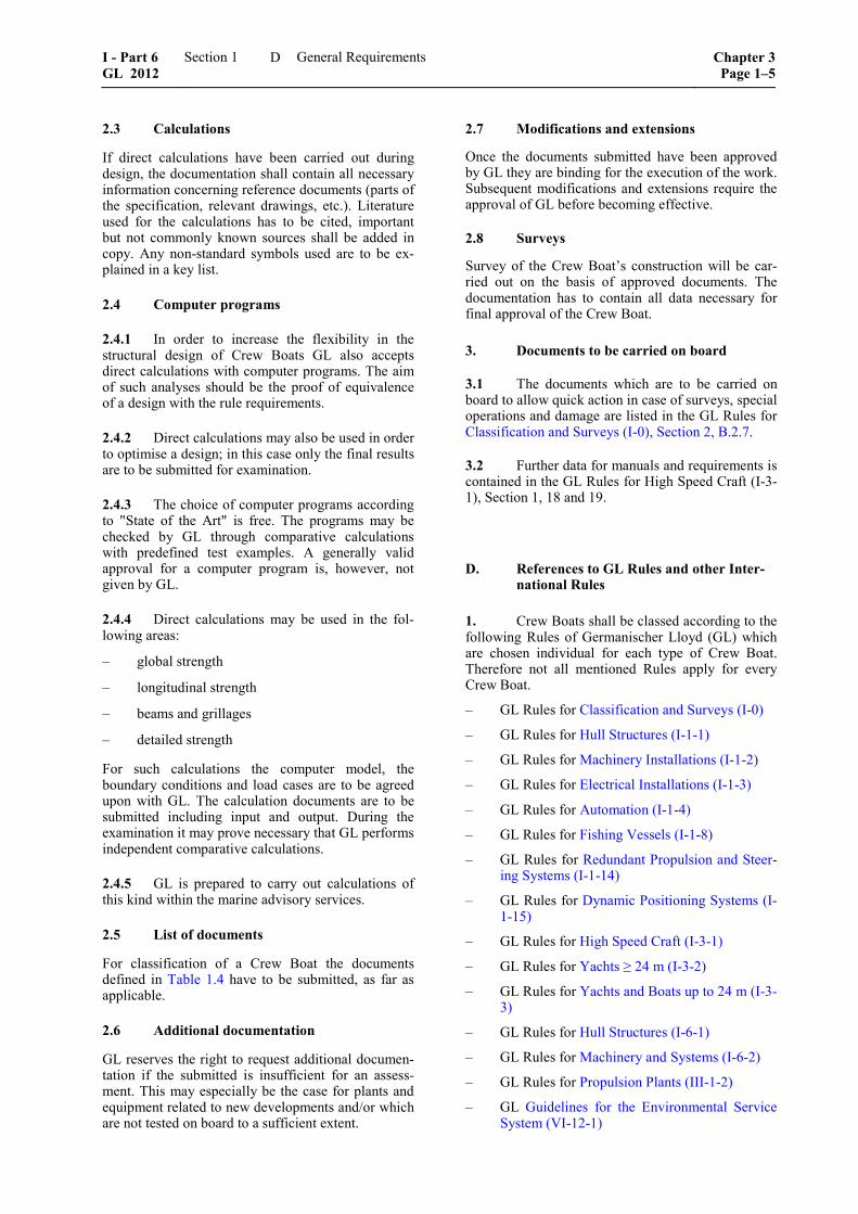
2.7 Modifications and extensions
Once the documents submitted have been approved by GL they are binding for the execution of the work. Subsequent modifications and extensions require the approval of GL before becoming effective.
2.8 Surveys
Survey of the Crew Boat’s construction will be car-ried out on the basis of approved documents. The documentation has to contain all data necessary for final approval of the Crew Boat.
3. Documents to be carried on board
3.1 The documents which are to be carried on board to allow quick action in case of surveys, special operations and damage are listed in the GL Rules for Classification and Surveys (I-0), Section 2, B.2.7.
3.2 Further data for manuals and requirements is contained in the GL Rules for High Speed Craft (I-3-1), Section 1, 18 and 19.
D. References to GL Rules and other Inter-national Rules
1. Crew Boats shall be classed according to the following Rules of Germanischer Lloyd (GL) which are chosen individual for each type of Crew Boat. Therefore not all mentioned Rules apply for every Crew Boat.
– GL Rules for Classification and Surveys (I-0)
– GL Rules for Hull Structures (I-1-1)
– GL Rules for Machinery Installations (I-1-2)
– GL Rules for Electrical Installations (I-1-3)
– GL Rules for Automation (I-1-4)
– GL Rules for Fishing Vessels (I-1-8)
– GL Rules for Redundant Propulsion and Steer-ing Systems (I-1-14)
– GL Rules for Dynamic Positioning Systems (I-1-15)
– GL Rules for High Speed Craft (I-3-1)
– GL Rules for Yachts ≥ 24 m (I-3-2)
– GL Rules for Yachts and Boats up to 24 m (I-3-3)
– GL Rules for Hull Structures (I-6-1)
– GL Rules for Machinery and Systems (I-6-2)
– GL Rules for Propulsion Plants (III-1-2)
– GL Guidelines for the Environmental Service System (VI-12-1)
I - Part 6 GL 2012
Section 1 General Requirements Chapter 3Page 1–5
D

2. The following international regulations and conventions are to be applied too: – SOLAS 2009– International Convention for the
Safety of Life at Sea, 2009, as amended, here-inafter referred to as “SOLAS 2009”
– MARPOL – International Convention for the Prevention of Pollution from Ships, 1973 in-cluding the 1978 Protocol, as amended, herein-after referred to as “MARPOL 73/78”
– IS Code – International Code on Intact Stabil-ity, 2008, as amended, hereinafter referred to as “IS Code”
– ICLL – International Convention on Load Lines, 1966, as amended, hereinafter referred to as “ICLL”
– SPS Code – Code of Safety for Special Pur-pose Ships, 2008, as amended, hereinafter re-ferred to as “SPS Code”
– HSC Code – International Code of Safety for High Speed Craft, 1994, as amended, hereinaf-ter referred to as “HSC Code”
– Hong Kong Convention – Honk Kong Inter-national Convention for the Safe and Environ-mentally Sound Recycling of Ships, 2009, hereinafter referred to as “Hong Kong Con-vention”
– several guidelines and recommendations given out by the IMO
– several ISO and DIN standards in their latest edition, as mentioned in the following sections
– IACS Recommendation No. 99
3. The Rules which are to be applied differ, according to the several types of Crew Boats as in Fig. 1.1 and Table 1.1.
E. Workmanship
1. The requirements for proper workmanship to be applied for Crew Boats are defined in the GL Rules for Hull Structures (I-6-1), Section 1, L.
2. It is recommended that the shipyard operates a quality assurance system, such as ISO 9001 or equivalent.
F. Ambient Conditions
1. General
The selection, layout and arrangement of the Crew Boat's structure and all shipboard machinery, equip-ment and appliances shall be such as to ensure unob-structed continuous operation under the ambient conditions specified in these Rules.
For all types of Crew Boats the same inclinations and environmental conditions as defined in 2 and 3 are to be applied. These conditions are substantially the conditions for worldwide operating seagoing ships.
GL may approve other conditions for Crew Boats operating only in special geographical areas.
2. Inclinations and movement of the Crew Boat
The permissible static and dynamic inclinations are specified in Table 1.2.
3. Environmental conditions
The environmental conditions to be applied are speci-fied in Table 1.3.
Chapter 3 Page 1–6
Section 1 General Requirements I - Part 6GL 2012
F
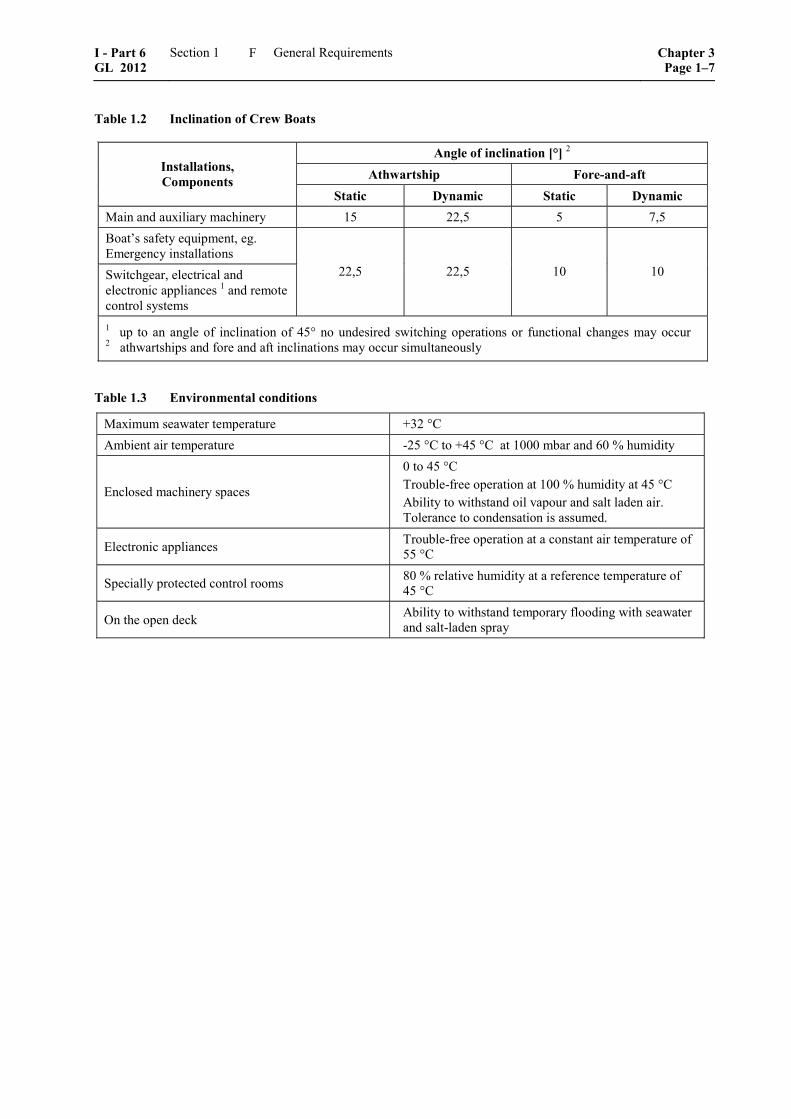
Table 1.2 Inclination of Crew Boats
Angle of inclination [°] 2 Athwartship Fore-and-aft Installations,
Components Static Dynamic Static Dynamic
Main and auxiliary machinery 15 22,5 5 7,5 Boat’s safety equipment, eg. Emergency installations Switchgear, electrical and electronic appliances 1 and remote control systems
22,5 22,5 10 10
1 up to an angle of inclination of 45° no undesired switching operations or functional changes may occur 2 athwartships and fore and aft inclinations may occur simultaneously
Table 1.3 Environmental conditions
Maximum seawater temperature +32 °C Ambient air temperature -25 °C to +45 °C at 1000 mbar and 60 % humidity
Enclosed machinery spaces
0 to 45 °C Trouble-free operation at 100 % humidity at 45 °C Ability to withstand oil vapour and salt laden air. Tolerance to condensation is assumed.
Electronic appliances Trouble-free operation at a constant air temperature of 55 °C
Specially protected control rooms 80 % relative humidity at a reference temperature of 45 °C
On the open deck Ability to withstand temporary flooding with seawater and salt-laden spray
I - Part 6 GL 2012
Section 1 General Requirements Chapter 3Page 1–7
F

Table 1.4 Documentation to be submitted for Classification of Crew Boats
Serial No. Description 1 2 3 4 5 6 7
8 9
10 11 12 13 14 15 16 17 18 19 20 21 22 23 24 25 26 27 28
29 30 31 32 33 34 35
36 37 38 39 40 41 42
General Requirements General arrangement plan Deck plan Technical specification Lines plan Tank arrangement plan Material specification for hull List of submitted drawings
Hull Structures and Ship Equipment Hull Midship section Other typical sections Bottom structure Engine room structure (including engine foundation) Shell expansion plan Ice strengthening, if applicable Decks Superstructures and deckhouses Bulkheads Rudder body Rudder stock Rudder bearing, pintles and couplings, etc. Large openings Special foundations Welded joints for steel or aluminium Coating plan NDT-plan (Non-Destructive-Testing) Equipment number and anchoring equipment Mooring equipment Crane foundations Foundations for personnel transfer arrangements
Supporting Calculation (Structure) Design loads summarized in a load plan Distribution of still water shear forces and bending moments Longitudinal strength calculation Geometry properties of significant hull girder cross sections Local stress calculations, if applicable Finite element analysis, if applicable Residual strength, if applicable
Safety Requirements of the Hull Closing appliances Information to calculation of freeboard Arrangement and details of exterior doors Arrangement and details of watertight doors Arrangement and details of hatches Arrangement and details of air pipes and ventilators Arrangement and details of side shell penetrations by scuppers and discharges
Chapter 3 Page 1–8
Section 1 General Requirements I - Part 6GL 2012
F
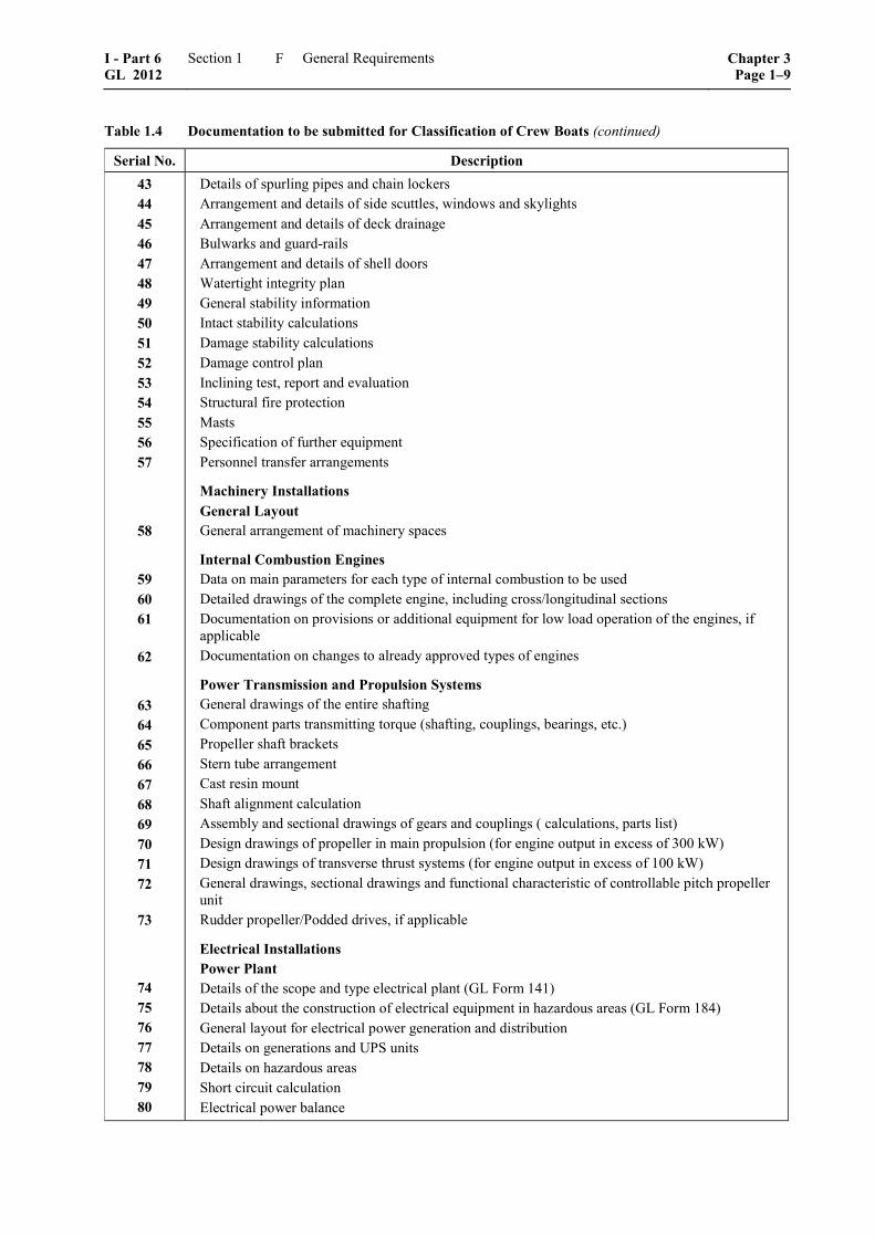
Table 1.4 Documentation to be submitted for Classification of Crew Boats (continued)
Serial No. Description 43 44 45 46 47 48 49 50 51 52 53 54 55 56 57
58
59 60 61
62
63 64 65 66 67 68 69 70 71 72
73
74 75 76 77 78 79 80
Details of spurling pipes and chain lockers Arrangement and details of side scuttles, windows and skylights Arrangement and details of deck drainage Bulwarks and guard-rails Arrangement and details of shell doors Watertight integrity plan General stability information Intact stability calculations Damage stability calculations Damage control plan Inclining test, report and evaluation Structural fire protection Masts Specification of further equipment Personnel transfer arrangements
Machinery Installations General Layout General arrangement of machinery spaces
Internal Combustion Engines Data on main parameters for each type of internal combustion to be used Detailed drawings of the complete engine, including cross/longitudinal sections Documentation on provisions or additional equipment for low load operation of the engines, if applicable Documentation on changes to already approved types of engines
Power Transmission and Propulsion Systems General drawings of the entire shafting Component parts transmitting torque (shafting, couplings, bearings, etc.) Propeller shaft brackets Stern tube arrangement Cast resin mount Shaft alignment calculation Assembly and sectional drawings of gears and couplings ( calculations, parts list) Design drawings of propeller in main propulsion (for engine output in excess of 300 kW) Design drawings of transverse thrust systems (for engine output in excess of 100 kW) General drawings, sectional drawings and functional characteristic of controllable pitch propeller unit Rudder propeller/Podded drives, if applicable
Electrical Installations Power Plant Details of the scope and type electrical plant (GL Form 141) Details about the construction of electrical equipment in hazardous areas (GL Form 184) General layout for electrical power generation and distribution Details on generations and UPS units Details on hazardous areas Short circuit calculation Electrical power balance
I - Part 6 GL 2012
Section 1 General Requirements Chapter 3Page 1–9
F
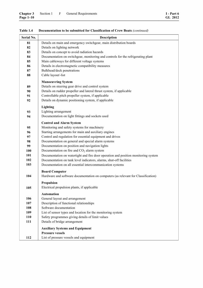
Table 1.4 Documentation to be submitted for Classification of Crew Boats (continued)
Serial No. Description 81 82 83 84 85 86 87 88
89 90 91 92
93 94
95 96 97 98 99
100 101 102 103
104
105
106 107 108 109 110 111
112
Details on main and emergency switchgear, main distribution boards Details on lighting network Details on concept to avoid radiation hazards Documentation on switchgear, monitoring and controls for the refrigerating plant Main cableways for different voltage systems Details in electromagnetic compatibility measures Bulkhead/deck penetrations Cable layout/-list
Manoeuvring System Details on steering gear drive and control system Details on rudder propeller and lateral thrust system, if applicable Controllable pitch propeller system, if applicable Details on dynamic positioning system, if applicable
Lighting Lighting arrangement Documentation on light fittings and sockets used
Control and Alarm System Monitoring and safety systems for machinery Starting arrangements for main and auxiliary engines Control and regulation for essential equipment and drives Documentation on general and special alarm systems Documentation on position and navigation lights Documentation on fire and CO2 alarm system Documentation on watertight and fire door operation and position monitoring system Documentation on tank level indicators, alarms, shut-off facilities Documentation on all essential intercommunication systems
Board Computer Hardware and software documentation on computers (as relevant for Classification)
Propulsion Electrical propulsion plants, if applicable
Automation General layout and arrangement Description of functional relationships Software documentation List of sensor types and location for the monitoring system Safety programmes giving details of limit values Details of bridge arrangement
Auxiliary Systems and Equipment Pressure vessels List of pressure vessels and equipment
Chapter 3 Page 1–10
Section 1 General Requirements I - Part 6GL 2012
F
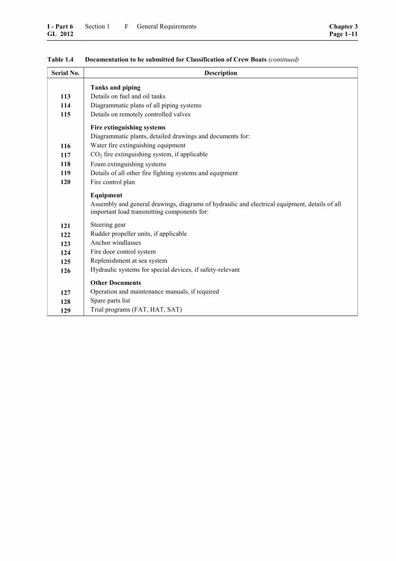
Table 1.4 Documentation to be submitted for Classification of Crew Boats (continued)
Serial No. Description
113 114 115
116 117 118 119 120
121 122 123 124 125 126
127 128 129
Tanks and piping Details on fuel and oil tanks Diagrammatic plans of all piping systems Details on remotely controlled valves
Fire extinguishing systems Diagrammatic plants, detailed drawings and documents for: Water fire extinguishing equipment CO2 fire extinguishing system, if applicable Foam extinguishing systems Details of all other fire fighting systems and equipment Fire control plan
Equipment Assembly and general drawings, diagrams of hydraulic and electrical equipment, details of all important load transmitting components for:
Steering gear Rudder propeller units, if applicable Anchor windlasses Fire door control system Replenishment at sea system Hydraulic systems for special devices, if safety-relevant
Other Documents Operation and maintenance manuals, if required Spare parts list Trial programs (FAT, HAT, SAT)
I - Part 6 GL 2012
Section 1 General Requirements Chapter 3Page 1–11
F


Section 2
Classification and Surveys
A. Classification
1. Confidentiality
For confidentiality explanations please see GL Rules for Classification and Surveys (I-0).
2. Classification of newbuildings
2.1 Detailed information about:
– order for Classification
– examination of construction particulars
– supervision of construction and trials
– reports, Certificates
and the relevant requirements to be applied for Crew Boats are defined in the GL Rules for Classification and Surveys (I-0), Section 2, D.
2.2 Class Certificate and Register
The issuance of the Class Certificate and the entering of the Crew Boat to the GL Register is defined in the GL Rules for Classification and Surveys (I-0), Section 2, A.3. and A.4.
3. Validity of Class
Detailed information about:
– period of Class
– prerequisites for validity of Class
– repairs
– conversions
– Class expiry
– laid-up Crew Boats/suspension of Class
– re-commissioning/re-admission of Class and the relevant requirements to be applied are de-fined in the GL Rules for Classification and Surveys (I-0), Section 2, B.
4. Admission to Class
For admission to class please see GL Rules for Classi-fication and Surveys (I-0).
B. Characters of Classification and Class Notations
1. Characters of Classification
The Characters of Classification for Crew Boats are to be defined as follows: – 100Ap for 100 % compliance with Rule re-
quirements for hull and Class period of p years (normally p = 5)
– all other Characters of Classification are identi-cal to 2.1, compare GL Rules for Classification and Surveys (I-0) Section 2, Table 2.1.
2. Notations
2.1 Notations defined in the GL Rules
2.1.1 For CREW BOAT 1 please refer to Fig. 1.1 Scheme for selection of rules to be applied according to the four main criteria.
2.1.2 For CREW BOAT 2 please refer to Fig. 1.1 Scheme for selection of rules to be applied according to the four main criteria
2.2 For Offshore Wind Farm Service Craft (OWFSC) please refer to the definition given in Sec-tion 1, B.6.
2.3 Crew boats intended for operations requiring higher manoeuvring and positioning abilities, reliabil-ity and/or availability shall be equipped with two identical, independent propulsors, each one of them capable to produce thrust in ahead and reverse direc-tion. The corresponding class notation for such instal-lations is RPw, and does not necessarily require inde-pendency of the feeding systems of these redundant propulsors e.g. cooling system, fuel system, etc. For higher redundancy /availability requirements the stan-dard class notations RP2x% or RP3x% may be taken into consideration. For higher positioning and ma-noeuvring requirements combined with extended availability in case of single failures in the propulsion or manoeuvring trains the standard class notations DP1, DP2 and DP3 may be applied. The requirements for RP2x% or even RP3x% fully cover up the re-quirements leading to the crew vessel dedicated class notation RPw. When RP2x% or RP3x% notation is granted the class notation RPw will not be explicitly mentioned in the character of classification. For ves-sels equipped with a dynamic positioning system see GL Rules for Dynamic Positioning Systems (I-1-15),
I - Part 6 GL 2012
Section 2 Classification and Surveys Chapter 3Page 2–1
B
Section 1, E. For vessels which in this context have to fulfil the requirements for redundant propulsion see GL Rules for Redundant Propulsion and Steering Systems (I-1-14).
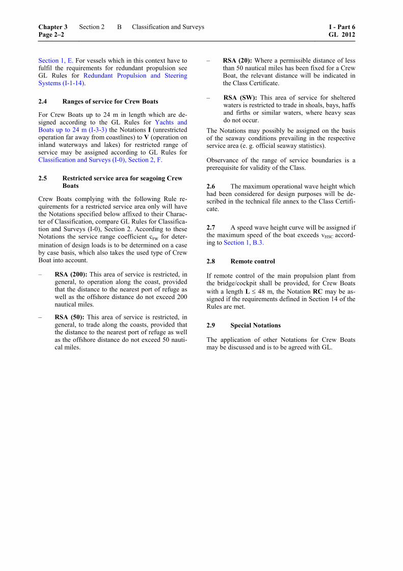
2.4 Ranges of service for Crew Boats
For Crew Boats up to 24 m in length which are de-signed according to the GL Rules for Yachts and Boats up to 24 m (I-3-3) the Notations I (unrestricted operation far away from coastlines) to V (operation on inland waterways and lakes) for restricted range of service may be assigned according to GL Rules for Classification and Surveys (I-0), Section 2, F.
2.5 Restricted service area for seagoing Crew Boats
Crew Boats complying with the following Rule re-quirements for a restricted service area only will have the Notations specified below affixed to their Charac-ter of Classification, compare GL Rules for Classifica-tion and Surveys (I-0), Section 2. According to these Notations the service range coefficient crw for deter-mination of design loads is to be determined on a case by case basis, which also takes the used type of Crew Boat into account.
– RSA (200): This area of service is restricted, in general, to operation along the coast, provided that the distance to the nearest port of refuge as well as the offshore distance do not exceed 200 nautical miles.
– RSA (50): This area of service is restricted, in general, to trade along the coasts, provided that the distance to the nearest port of refuge as well as the offshore distance do not exceed 50 nauti-cal miles.
– RSA (20): Where a permissible distance of less than 50 nautical miles has been fixed for a Crew Boat, the relevant distance will be indicated in the Class Certificate.
– RSA (SW): This area of service for sheltered waters is restricted to trade in shoals, bays, haffs and firths or similar waters, where heavy seas do not occur.
The Notations may possibly be assigned on the basis of the seaway conditions prevailing in the respective service area (e. g. official seaway statistics).
Observance of the range of service boundaries is a prerequisite for validity of the Class.
2.6 The maximum operational wave height which had been considered for design purposes will be de-scribed in the technical file annex to the Class Certifi-cate.
2.7 A speed wave height curve will be assigned if the maximum speed of the boat exceeds vHSC accord-ing to Section 1, B.3.
2.8 Remote control
If remote control of the main propulsion plant from the bridge/cockpit shall be provided, for Crew Boats with a length L ≤ 48 m, the Notation RC may be as-signed if the requirements defined in Section 14 of the Rules are met.
2.9 Special Notations
The application of other Notations for Crew Boats may be discussed and is to be agreed with GL.
Chapter 3 Page 2–2
Section 2 Classification and Surveys I - Part 6GL 2012
B
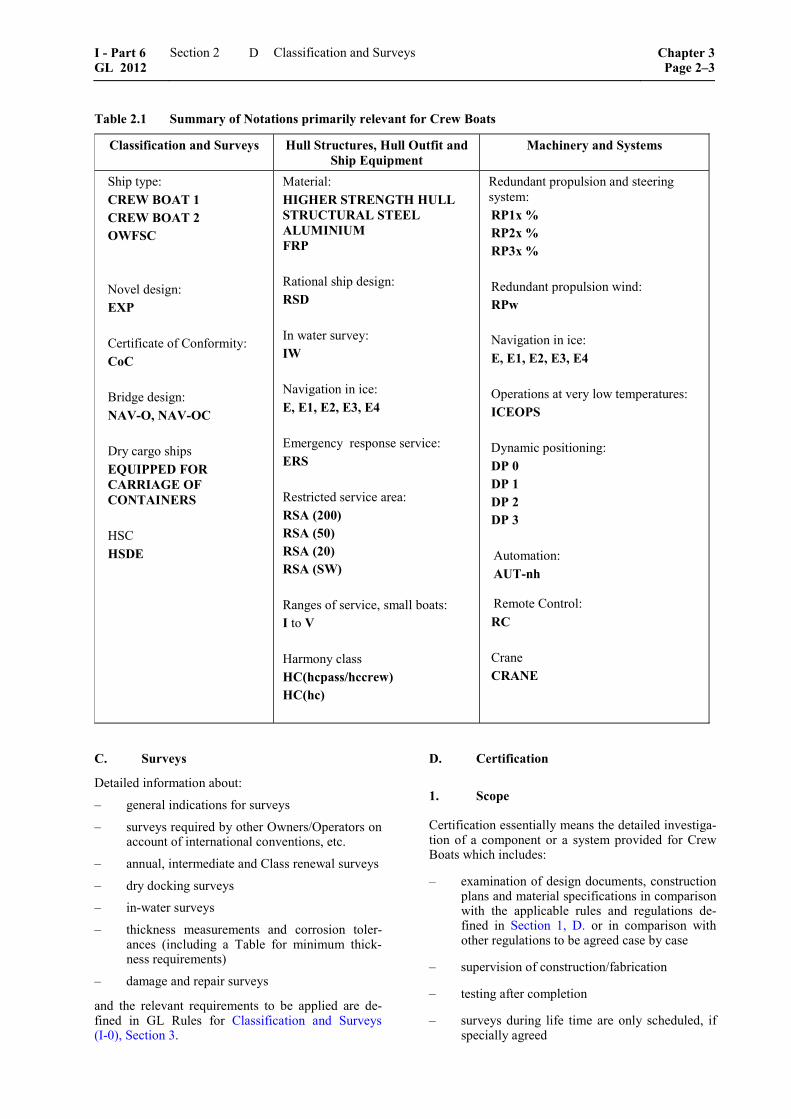
Table 2.1 Summary of Notations primarily relevant for Crew Boats
Classification and Surveys Hull Structures, Hull Outfit and Ship Equipment
Machinery and Systems
Ship type: CREW BOAT 1 CREW BOAT 2 OWFSC Novel design: EXP Certificate of Conformity: CoC Bridge design: NAV-O, NAV-OC Dry cargo ships EQUIPPED FOR CARRIAGE OF CONTAINERS
HSC HSDE
Material: HIGHER STRENGTH HULL STRUCTURAL STEEL ALUMINIUM FRP Rational ship design: RSD In water survey: IW Navigation in ice: E, E1, E2, E3, E4 Emergency response service: ERS Restricted service area: RSA (200) RSA (50) RSA (20) RSA (SW) Ranges of service, small boats: I to V Harmony class HC(hcpass/hccrew) HC(hc)
Redundant propulsion and steering system: RP1x % RP2x % RP3x % Redundant propulsion wind: RPw
Navigation in ice: E, E1, E2, E3, E4 Operations at very low temperatures: ICEOPS Dynamic positioning: DP 0 DP 1 DP 2 DP 3 Automation: AUT-nh
Remote Control: RC Crane CRANE
C. Surveys
Detailed information about:
– general indications for surveys
– surveys required by other Owners/Operators on account of international conventions, etc.
– annual, intermediate and Class renewal surveys
– dry docking surveys
– in-water surveys
– thickness measurements and corrosion toler-ances (including a Table for minimum thick-ness requirements)
– damage and repair surveys
and the relevant requirements to be applied are de-fined in GL Rules for Classification and Surveys (I-0), Section 3.
D. Certification
1. Scope
Certification essentially means the detailed investiga-tion of a component or a system provided for Crew Boats which includes:
– examination of design documents, construction plans and material specifications in comparison with the applicable rules and regulations de-fined in Section 1, D. or in comparison with other regulations to be agreed case by case
– supervision of construction/fabrication
– testing after completion
– surveys during life time are only scheduled, if specially agreed
I - Part 6 GL 2012
Section 2 Classification and Surveys Chapter 3Page 2–3
D

2. Application
2.1 The application for Certification is to be made in writing to GL by the manufacturer or opera-tor.
2.2 To facilitate a smooth and efficient approval process documents for the component/equipment are to be submitted electronically via GLOBE 1 for ap-proval. In specific cases and following prior agree-ment with GL they can also be submitted in paper form in triplicate. The scope of the documents to be submitted depends on the type and equipment and is to be agreed on case by case basis, compare also the listing given in Section 1, C.
2.3 Surveys which have to be performed by GL are to be made known to GL in due time.
–––––––––––––– 1 Detailed information about the secured GL system GLOBE
can be found on GL’s website www.gl-group.com/globe.
3. Certificate
3.1 After completion and successful testing a Certificate will be issued for the component/system by GL.
3.2 The Certificate certifies the technical condi-tion of the component/system at the time of the tests and approvals by GL. In addition it will be confirmed that no safety reservations are opposing the operation of the component/system.
3.3 The validity of the Certificate is 5 years at maximum and can be prolonged after renewed tests. The Certificate looses its validity if substantial changes have been performed respectively if the component/system has been severely damaged and the change or the repair has not been agreed and approved by GL.
Chapter 3 Page 2–4
Section 2 Classification and Surveys I - Part 6GL 2012
D
Section 3
Materials and Corrosion Protection
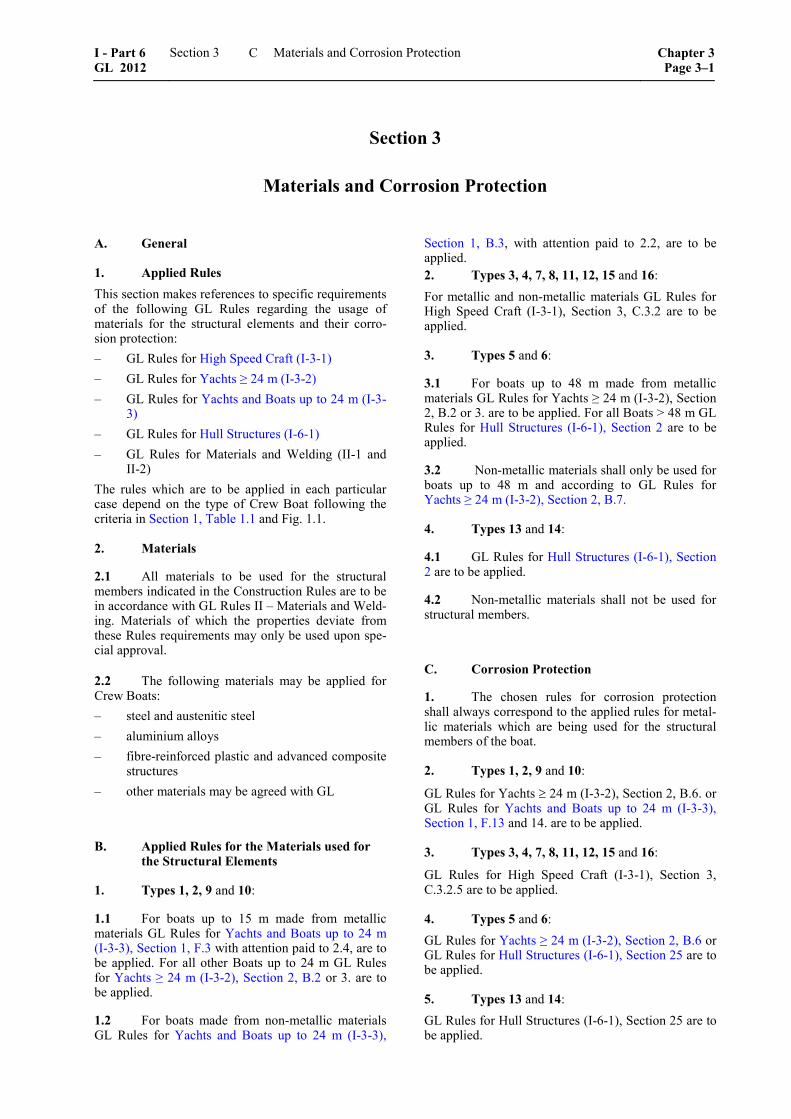
A. General
1. Applied Rules This section makes references to specific requirements of the following GL Rules regarding the usage of materials for the structural elements and their corro-sion protection: – GL Rules for High Speed Craft (I-3-1) – GL Rules for Yachts ≥ 24 m (I-3-2) – GL Rules for Yachts and Boats up to 24 m (I-3-
3) – GL Rules for Hull Structures (I-6-1) – GL Rules for Materials and Welding (II-1 and
II-2) The rules which are to be applied in each particular case depend on the type of Crew Boat following the criteria in Section 1, Table 1.1 and Fig. 1.1.
2. Materials
2.1 All materials to be used for the structural members indicated in the Construction Rules are to be in accordance with GL Rules II – Materials and Weld-ing. Materials of which the properties deviate from these Rules requirements may only be used upon spe-cial approval.
2.2 The following materials may be applied for Crew Boats: – steel and austenitic steel – aluminium alloys – fibre-reinforced plastic and advanced composite
structures – other materials may be agreed with GL
B. Applied Rules for the Materials used for the Structural Elements
1. Types 1, 2, 9 and 10:
1.1 For boats up to 15 m made from metallic materials GL Rules for Yachts and Boats up to 24 m (I-3-3), Section 1, F.3 with attention paid to 2.4, are to be applied. For all other Boats up to 24 m GL Rules for Yachts ≥ 24 m (I-3-2), Section 2, B.2 or 3. are to be applied.
1.2 For boats made from non-metallic materials GL Rules for Yachts and Boats up to 24 m (I-3-3),
Section 1, B.3, with attention paid to 2.2, are to be applied. 2. Types 3, 4, 7, 8, 11, 12, 15 and 16: For metallic and non-metallic materials GL Rules for High Speed Craft (I-3-1), Section 3, C.3.2 are to be applied.
3. Types 5 and 6:
3.1 For boats up to 48 m made from metallic materials GL Rules for Yachts ≥ 24 m (I-3-2), Section 2, B.2 or 3. are to be applied. For all Boats > 48 m GL Rules for Hull Structures (I-6-1), Section 2 are to be applied.
3.2 Non-metallic materials shall only be used for boats up to 48 m and according to GL Rules for Yachts ≥ 24 m (I-3-2), Section 2, B.7.
4. Types 13 and 14:
4.1 GL Rules for Hull Structures (I-6-1), Section 2 are to be applied.
4.2 Non-metallic materials shall not be used for structural members.
C. Corrosion Protection
1. The chosen rules for corrosion protection shall always correspond to the applied rules for metal-lic materials which are being used for the structural members of the boat.
2. Types 1, 2, 9 and 10:
GL Rules for Yachts ≥ 24 m (I-3-2), Section 2, B.6. or GL Rules for Yachts and Boats up to 24 m (I-3-3), Section 1, F.13 and 14. are to be applied.
3. Types 3, 4, 7, 8, 11, 12, 15 and 16:
GL Rules for High Speed Craft (I-3-1), Section 3, C.3.2.5 are to be applied.
4. Types 5 and 6: GL Rules for Yachts ≥ 24 m (I-3-2), Section 2, B.6 or GL Rules for Hull Structures (I-6-1), Section 25 are to be applied.
5. Types 13 and 14: GL Rules for Hull Structures (I-6-1), Section 25 are to be applied.
I - Part 6 GL 2012
Section 3 Materials and Corrosion Protection Chapter 3Page 3–1
C


Section 4
Hull Structures
A. General
This section makes references to specific requirements of the following GL Rules regarding the Crew Boat’s hull structure’s dimensioning and design:
– GL Rules for High Speed Craft (I-3-1)
– GL Rules for Yachts ≥ 24 m (I-3-2)
– GL Rules for Yachts and Boats up to 24 m (I-3-3)
– GL Rules for Hull Structures (I-6-1)
– GL Rules for Materials and Welding (II-1 and II-2)
The rules which are to be applied in each particular case depend on the type of Crew Boat following the criteria in Section 1, Table 1.1 and Fig. 1.1.
B. Design Principles
1. All types except 1, 5, 9 and 13:
GL Rules for High Speed Craft (I-3-1), Section 3, C3.7 resp. C3.8 are to be applied according to the material used for the structural members. Further calculations can be found in C3.6.
2. Types 1, 5 and 9:
2.1 For boats up to 48 m made from metallic materials GL Rules for Yachts ≥ 24 m (I-3-2), Section 2, C. and D.2.1 are to be applied. For boats > 48 m the GL Rules mentioned in 3 are to be applied.
2.2 Non-metallic materials shall only be used for boats up to 48 m and according to GL Rules for Yachts ≥ 24 m (I-3-2), Section 2, E.2.1.
3. Type 13:
GL Rules for Hull Structures (I-6-1), Section 3 are to be applied.
C. Design Loads
1. All types except 1, 5, 9 and 13:
GL Rules for High Speed Craft (I-3-1), Section 3, C3.4 and C3.5 are to be applied
2. Types 1, 5 and 9:
For all boats up to 48 m GL Rules for Yachts ≥ 24 m (I-3-2), Section 2, D.3 or E.3. are to be applied accord-ing to the material used for the structural members. For boats > 48m the GL Rules mentioned in 3 are to be applied.
3. Type 13:
GL Rules for Hull Structures (I-6-1), Section 4 are to be applied.
D. Longitudinal Strength
1. All types 1, 5, 9 and 13:
GL Rules for High Speed Craft (I-3-1), Section 3, C3.7.3.1 or C3.8.3 are to be applied according to the material which is used for the structural members.
2. Types 1, 5, 9 and 13:
GL Rules for Hull Structures (I-6-1), Section 5 are to be applied.
E. Bottom and Shell Structures
1. All types except 1, 5, 9 and 13:
1.1 For boats made from metallic materials GL Rules for High Speed Craft (I-3-1), Section 3, C3.7.7 to C3.7.9 are to be applied.
1.2 For boats made from non-metallic materials GL Rules for High Speed Craft (I-3-1), Section 3, C3.8.4 to C3.8.6 are to be applied.
2. Types 1 and 9:
2.1 For boats up to 15 m made from metallic materials GL Rules for Yachts and Boats up to 24 m (I-3-3), Section 1, F 8 with attention paid to 2.4, are to be applied. For boats > 15m the GL Rules mentioned in 3 are to be applied.
2.2 For boats made from non-metallic materials GL Rules for Yachts and Boats up to 24 m (I-3-3), Section 1, B.7.4, with attention paid to 2.2, are to be applied.
I - Part 6 GL 2012
Section 4 Hull Structures Chapter 3Page 4–1
E

3. Type 5:
3.1 For boats up to 48 m made from metallic materials GL Rules for Yachts ≥ 24 m (I-3-2), Section 2, D.2.6 are to be applied. For boats > 48 m the GL Rules mentioned in 4 are to be applied.
3.2 Non-metallic materials shall only be used for boats up to 48 m and according to GL Rules for Yachts ≥ 24 m (I-3-2), Section 2, E.2.5.
4. Type 13:
GL Rules for Hull Structures (I-6-1), Section 6 and 8 are to be applied.
F. Decks and Longitudinal Walls
1. All types except 1, 5, 9 and 13:
1.1 For boats made from metallic materials GL Rules for High Speed Craft (I-3-1), Section 3, C3.7.7 to C3.7.9 are to be applied.
1.2 For boats made from non-metallic materials GL Rules for High Speed Craft (I-3-1), Section 3, C3.8.4 to C3.8.6 are to be applied.
2. Types 1 and 9:
2.1 For boats up to 15 m made from metallic materials GL Rules for Yachts and Boats up to 24 m (I-3-3), Section 1, F.9.2 and 10 with attention paid to 2.4, are to be applied. For boats > 15m the GL Rules mentioned in 3 are to be applied.
2.2 For boats made from non-metallic materials GL Rules for Yachts and Boats up to 24 m (I-3-3), Section 1, B.7.3 and 8, with attention paid to 2.2, are to be applied.
3. Types 5:
3.1 For boats up to 48 m made from metallic materials GL Rules for Yachts ≥ 24 m (I-3-2), Section 2, D.2.10 are to be applied. For boats > 48 m the GL Rules mentioned in 4 are to be applied.
3.2 Non-metallic materials shall only be used for boats up to 48 m and according to GL Rules for Yachts ≥ 24 m (I-3-2), Section 2, E.2.9.
4. Type 13:
GL Rules for Hull Structures (I-6-1), Section 7 and 10 are to be applied.
G. Welded Joints
For all types of Crew Boats made of metallic materials GL Rules for Hull Structures (I-6-1), Section 19are to be applied. Additionally the welding work has to comply with the GL Rules for Welding (II-3).
H. Fatigue Strength
For all types of Crew Boats made from metallic mate-rials the GL Rules for Hull Structures (I-6-1), Section 20 are to be applied.
I. Noise and Vibration
For all types of Crew Boats the GL Rules for Hull Structures (I-6-1), Section 1, E. are to be applied.
J. Transverse and Watertight Bulkheads and Walls
1. All types except 1, 5, 9 and 13:
GL Rules for High Speed Craft (I-3-1), Section 3, C3.7 resp. C3.8 are to be applied.
2. Types 1 and 9:
2.1 For boats up to 15 m made from metallic materials GL Rules for Yachts and Boats up to 24 m (I-3-3), Section 1, F.5 with attention paid to 2.4, are to be applied. For boat >15 m the GL Rules mentioned in 3 are to be applied.
2.2 For boats made from non-metallic materials GL Rules for Yachts and Boats up to 24 m (I-3-3), Section 1, B.7, with attention paid to 2.2, are to be applied.
3. Types 5:
3.1 For boats up to 48 m made from metallic materials GL Rules for Yachts ≥ 24 m (I-3-2), Section 2, D.2.3 are to be applied. For boats > 48 m the GL Rules mentioned in 4 are to be applied.
3.2 Non-metallic materials shall only be used for boats up to 48 m and according to GL Rules for Yachts ≥ 24 m (I-3-2), Section 2, E.2.3.
4. Types 13:
GL Rules for Hull Structures (I-6-1), Section 9 and 11 are to be applied.
Chapter 3 Page 4–2
Section 4 Hull Structures I - Part 6GL 2012
J
K. Tank Structures
1. Types 1, 2, 5 and 6:
GL Rules for Yachts ≥ 24 m (I-3-2), Section 2, H. are to be applied.
2. Types 3, 4, 7, 8, 11, 12, 15 and 16:
GL Rules for High Speed Craft (I-3-1), Section 3 and 10 are to be applied.
3. Types 9, 10, 13 and 14:
GL Rules for Hull Structures (I-6-1), Section 12 are to be applied.
L. Stem and Stern Frame Structures
For all types of Crew Boats made from metallic mate-rials the GL Rules for Hull Structures (I-6-1), Section 13 are to be applied.
M. Rudder and Manoeuvring Arrangements
1. Types 1, 2, 5, 6, 9, 10, 13 and 14:
GL Rules for Hull Structures (I-6-1), Section 14 are to be applied.
2. Types 3, 4, 7, 8, 11, 12, 15 and 16:
GL Rules for High Speed Craft (I-3-1), Section 3, C3.10 are to be applied.
N. Strengthening for Navigation in Ice
For the requirements for the Ice class notation GL Rules for Hull Structures (I-6-1), Section 15 are to be applied
O. Superstructures and Deckhouses
1. Types 1, 2, 9 and 10:
1.1 For boats up to 15 m made from metallic materials GL Rules for Yachts and Boats up to 24 m (I-3-3), Section 1, F.11 with attention paid to 2.4, are to be applied. For boats > 15 m the GL Rules men-tioned in 3 are to be applied.
1.2 For boats made from non-metallic materials GL Rules for Yachts and Boats up to 24 m (I-3-3), Section 1, B.8, with attention paid to 2.2, are to be applied.
2. Types 3, 4, 7, 8, 11, 12, 15 and 16:
GL Rules for High Speed Craft (I-3-1), Section 3, C3.7 resp. C3.8 are to be applied.
3. Types 5 and 6:
3.1 For boats up to 48 m made from metallic materials GL Rules for Yachts ≥ 24 m (I-3-2), Section 2, D.2.11 are to be applied. For boats > 48 m the GL Rules mentioned in 4 are to be applied.
3.2 Non-metallic materials shall only be used for boats up to 48 m and according to GL Rules for Yachts ≥ 24 m (I-3-2), Section 2, E.2.10.
4. Types 13 and 14:
GL Rules for Hull Structures (I-6-1), Section 16 are to be applied.
P. Recommendation for Boat Landing and OSP Transfer for Offshore Wind Installa-tions
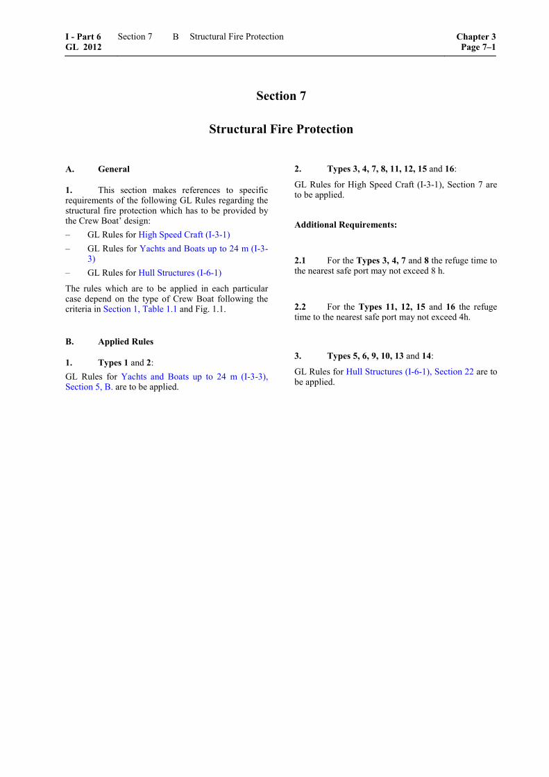
1. To ensure the safe transfer of personnel be-tween the Crew Boat and the various offshore installa-tions a well thought through design of the fenders is necessary.
Neither the offshore installation nor the vessel should be damaged during the landing and transfer operation. For designing the vessel’s front part the typical boat landing of offshore wind installations in the intended area of operations should be taken into account.
A matching design greatly enhances the safety of persons and prevents bigger damage to the offshore installations and the vessel. Fig. 4.1 shows a typical boat landing arrangement.
������������� ��������� ��
��������������������������������� ������ ��������������������
�������� �
��������
�� ���������
Fig. 4.1 Typical boat landing arrangement
2. The following guidance may be used to de-sign fenders attached to the Crew Boat:
2.1 Two prerequisites are made for the following calculations:
– the fender absorbs all energy of the impact
– the stiffness value c is constant, giving the fender a linear characteristic
I - Part 6 GL 2012
Section 4 Hull Structures Chapter 3Page 4–3
P
2.2 Given the intention to approach the boat landing at zero speed, the actual speed is mainly de-termined by the local environmental conditions. This allows the following estimation of the impact speed:
v ≈ ½ · Hs
with:
v = speed at the moment of impact [m/s]
Hs = maximum permissible significant wave height [m]
2.3 The energy which needs to be absorbed by the fenders depends on the impact speed and mass of the craft. An estimation can be calculated as follows:
E = ½ · a · Δ · (½ · Hs)2
with:
E = absorbed energy [kNm]
a = added mass coefficient for the hydrodynamic mass of the hull due to the surrounding water
= 1.4 for sideways landings
= 1.1 for bow or stern landings
Δ = displacement of the vessel [t]
2.4 With the calculated energy and the stiffness value of the chosen fender, the needed fender dimen-sions can be calculated:
f = 2 E / c⋅
with:
c = stiffness value [kN/m]
f = fender deflection [m]
Chapter 3 Page 4–4
Section 4 Hull Structures I - Part 6GL 2012
P

Section 5
Anchoring and Mooring Equipment
A. General This section makes references to specific requirements of the following GL Rules regarding the Crew Boat’s anchoring and mooring equipment:
– GL Rules for High Speed Craft (I-3-1)
– GL Rules for Yachts ≥ 24 m (I-3-2)
– GL Rules for Hull Structures (I-6-1)
The rules which are to be applied in each particular case depend on the type of Crew Boat following the criteria in Section 1, Table 1.1 and Fig. 1.1.
B. Applied Rules
1. All types except 1, 5, 9 and 13:
GL Rules for High Speed Craft (I-3-1), Section 6, following the monohull or multiple hull criteria, are to be applied.
2. Types 1 and 5:
GL Rules for Yachts ≥ 24 m (I-3-2), Section 2, K. are to be applied.
3. Types 9 and 13:
GL Rules for Hull Structures (I-6-1), Section 18 are to be applied.
I - Part 6 GL 2012
Section 5 Anchoring and Mooring Equipment Chapter 3Page 5–1
B


Section 6
Hull Outfit
A. General
1. This section makes references to specific requirements of the following GL Rules and other regulations regarding the Crew Boat’s hull outfit:
– GL Rules for Hull Structures (I-1-1)
– GL Rules for Yachts and Boats up to 24 m (I-3-3)
– GL Rules for Hull Structures (I-6-1)
– ICLL
– SOLAS 2009
– ISO 3903
– ISO 5480 The rules which are to be applied in each particular case depend on the type of Crew Boat following the criteria in Section 1, Table 1.1 and Fig. 1.1.
B. Freeboard
1. Types 1 to 4 and Types 9 to 12:
The draught is depending on the stability calculation.
Additional Requirements:
1.1 For the Types 9 to 12 the collision bulkhead has to be built according to GL Rules for Hull Struc-tures (I-6-1), Section 11, A.2.1.
2. Types 5 to 8 and Types 13 to 16:
ICLL Chapter III “Freeboards” is to be applied.
C. Hatches
1. Types 1 to 4 and Types 9 to 12:
GL Rules for Yachts and Boats up to 24 m (I-3-3), Section 5, A.5 and 6. are to be applied.
Additional Requirements:
1.1 Hatches positioned on the flush deck have to be watertight. All other hatches have to be weather-tight.
1.2 For the Types 1 to 4 the height of the coam-ings may not be less than:
– 150 mm for openings to spaces above the weather deck
– 460 mm for all other areas
1.3 For the Types 9 to 12 the height of the coam-ings may not be less than:
– 380 mm for openings to spaces above the weather deck
– 600 mm for all other areas
2. Types 5 to 8 and Types 13 to 16:
GL Rules for Hull Structures (I-6-1), Section 17 are to be applied. For hatches which are bigger than the dimensions mentioned in I-6-1 or when they are used to carry loads, GL Rules for Hull Structures (I-1-1), Section 17 are to be applied.
D. Doors
1. Types 1 to 4 and Types 9 to 12:
GL Rules for Yachts and Boats up to 24 m (I-3-3), Section 5, A.5. and 6. are to be applied.
Additional Requirements:
1.1 All doors have to be weathertight.
1.2 For Types 1 to 4 the height of the doorway sills may not be less than:
– 150 mm in side walls and back walls that are accessible from the main deck
– 380 mm above the cockpit deck in back walls that are accessible from the cockpit
– 460 mm anywhere if this access leads directly into the space.
1.3 For Types 9 to 12 the height of the doorway sills may not be less than:
– 380 mm in side walls and back walls that are accessible from the main deck
– 600 mm above the cockpit deck in back walls that are accessible from the cockpit
I - Part 6 GL 2012
Section 6 Hull Outfit Chapter 3Page 6–1
D

– 600 mm anywhere if this access leads directly into the space.
2. Types 5 to 8 and Types 13 to 16:
GL Rules for Hull Structures (I-6-1), Section 17, A. and B. are to be applied.
E. Watertight Doors
1. Types 1 to 4:
GL Rules for Yachts and Boats up to 24 m (I-3-3), Section 5 are to be applied.
2. Types 5 to 16:
GL Rules for Hull Structures (I-6-1), Section 21, C. are to be applied. SOLAS 2009, Chapter II-1, Part B-2, Regulations 13 and 13-1 may also be referred to.
F. Side Scuttles, Windows and Skylights
1. Types 1 to 4 and Types 9 to 12:
GL Rules for Yachts and Boats up to 24 m (I-3-3), Section 5, A.7. are to be applied.
Additional Requirements:
1.1 For the Types 9 to 12 the ISO 3903 is also to be applied.
1.2 The window panes have to be of toughened safety glass.
2. Types 5 to 8 and Types 13 to 16:
GL Rules for Hull Structures (I-6-1), Section 21, D. are to be applied.
Additional Requirements:
2.1 Side scuttles and windows at the side shell in the second tier shall be provided with hinged inside deadlights capable of being closed and secured weathertight if the superstructure protects a direct access to an opening leading below or is considered buoyant in the stability calculations.
2.2 Side scuttles and windows in side bulkheads set inboard from the side shell in the second tier, which protect a direct access below spaces listed in Hull Structures (I-6-1), Section 21, D.1.5, shall be provided with either hinged inside deadlights or, where they are accessible, permanently attached ex-ternal storm covers which are capable of being closed and secured weathertight.
2.3 Cabin bulkheads and doors in the second tier and above separating side scuttles and windows from
a direct access leading below or if the second tier is considered buoyant in the stability calculations, may be accepted in place of deadlights or storm covers fitted to the side scuttles and windows.
G. Air Pipes
1. Types 1 to 4 and Types 9 to 12:
GL Rules for Yachts and Boats up to 24 m (I-3-3), Section 5, A.5. and 6. are to be applied.
Additional Requirements:
1.1 All air pipes have to be equipped with suit-able closing appliances that close automatically.
1.2 For the Types 1 to 4 the height of the coam-ings may not be less than: – 300 mm where the deck is less 0,05 L above the
design waterline – 150 mm for all other decks
1.3 For the Types 9 to 12 the height of the coam-ings may not be less than: – 600 mm where the deck is less than 0,05 L
above the design waterline – 380 mm for all other decks
2. Types 5 to 8 and Types 13 to 16:
GL Rules for Hull Structures (I-6-1), Section 21, F. are to be applied.
Additional Requirements:
2.1 All Air pipes shall be provided with auto-matic closing appliances.
2.2 Where the heights of the air pipe may inter-fere with the working of the ship, a lower height may be approved, provided that the Administration is satis-fied that the closing arrangements and other circum-stances justify a lower height.
H. Ventilators
1. Types 1 to 4 and Types 9 to 12:
GL Rules for Yachts and Boats up to 24 m (I-3-3), Section 5, A.5. and 6. are to be applied.
Additional Requirements:
1.1 All Ventilators have to be weathertight, unless the coaming is higher than 1 m and the opening does not face forward.
Chapter 3 Page 6–2
Section 6 Hull Outfit I - Part 6GL 2012
H

1.2 For the Types 1 to 4 the height of the coam-ings may not be less than:
– 150 mm for openings to spaces above the weather deck
– 460 mm for all other areas
1.3 For the Types 9 to 12 the height of the coam-ings may not be less than:
– 380 mm for openings to spaces above the weather deck
– 600 mm for all other areas
2. Types 5 to 8 and Types 13 to 16:
GL Rules for Hull Structures (I-6-1), Section 21, G. are to be applied.
Additional Requirements:
2.1 In exposed locations, the height of coamings may be increased to the satisfaction of the Administra-tion.
I. Guard-Rails
1. Types 1 to 4 and Types 9 to 12:
ISO 5480 is to be applied.
2. Types 5 to 8 and Types 13 to 16:
GL Rules for Hull Structures (I-6-1), Section 21, M. are to be applied.
Additional Requirements:
2.1 Guard rails fitted on superstructure and free-board decks shall have at least three courses. The opening below the lowest course of the guard rails shall not exceed 230 mm. The other courses shall be not more than 380 mm apart. In the case of ships with rounded gunwales the guard rail supports shall be placed on the flat of the deck. In other locations, guardrails with at least two courses shall be fitted.
Guard rails shall comply with the following provi-sions:
– fixed, removable or hinged stanchions shall be fitted about 1,5 m apart. Removable or hinged stanchions shall be capable of being locked in the upright position
– at least every third stanchion shall be supported by a bracket or stay
– where necessary for the normal operation of the ship, steel wire ropes may be accepted in lieu of guard rails. Wires shall be made taut by means of turnbuckles
– where necessary for the normal operation of the ship, chains fitted between two fixed stanchions and/or bulwarks are acceptable in lieu of guard rails
I - Part 6 GL 2012
Section 6 Hull Outfit Chapter 3Page 6–3
I

Section 7
Structural Fire Protection
A. General
1. This section makes references to specific requirements of the following GL Rules regarding the structural fire protection which has to be provided by the Crew Boat’ design: – GL Rules for High Speed Craft (I-3-1) – GL Rules for Yachts and Boats up to 24 m (I-3-
3) – GL Rules for Hull Structures (I-6-1)
The rules which are to be applied in each particular case depend on the type of Crew Boat following the criteria in Section 1, Table 1.1 and Fig. 1.1.
B. Applied Rules
1. Types 1 and 2: GL Rules for Yachts and Boats up to 24 m (I-3-3), Section 5, B. are to be applied.
2. Types 3, 4, 7, 8, 11, 12, 15 and 16:
GL Rules for High Speed Craft (I-3-1), Section 7 are to be applied.
Additional Requirements:
2.1 For the Types 3, 4, 7 and 8 the refuge time to the nearest safe port may not exceed 8 h.
2.2 For the Types 11, 12, 15 and 16 the refuge time to the nearest safe port may not exceed 4h.
3. Types 5, 6, 9, 10, 13 and 14:
GL Rules for Hull Structures (I-6-1), Section 22 are to be applied.
I - Part 6 GL 2012
Section 7 Structural Fire Protection Chapter 3Page 7–1
B

Section 8
Intact and Damage Stability
A. General
1. This section makes references to specific requirements of the following GL Rules and other regulations regarding the stability cases of the Crew Boat:
– GL Rules for High Speed Craft (I-3-1)
– GL Rules for Hull Structures (I-6-1)
– International Code on Intact Stability 2008 (IS Code)
– SOLAS 2009
– IS Code
The rules which are to be applied in each particular case depend on the type of Crew Boat following the criteria in Section 1, Table 1.1 and Fig. 1.1.
B. Intact Stability
1. Types 1, 5 and 13:
Intact Stability Criteria of IS Code, Part A, chapter 2.2 and 2.3 are to be applied. GL Rules for Hull Struc-tures (I-6-1), Section 23 may also be referred to.
2. Types 2, 6 and 14:
Intact Stability Criteria of IS Code, Part B, chapter 2.4 are to be applied, if a vessel’s characteristic renders the application of the Intact Stability Criteria of IS Code, Part A, chapter 2.2 impracticable. GL Rules for Hull Structures (I-6-1), Section 23 may also be re-ferred to.
3. Types 3, 4, 7 and 8:
GL Rules for High Speed Craft (I-3-1), Section 2, A. are to be applied.
4. Types 9 to 12 and Types 15 and 16:
GL Rules for High Speed Craft (I-3-1), Section 2, B. are to be applied.
C. Damage Stability 1. Types 1 and 2:
No damage stability is required unless requested from Administration.
2. Types 3, 4, 7 and 8:
Regarding the 1-compartment status, GL Rules for High Speed Craft (I-3-1), Section 2, A.2.6 are to be applied. Annex 7 resp. Annex 8 shall be used for the calculation of the stability criteria.
Additional Requirements:
2.1 For the Types 3 and 4 raking damages ac-cording to 2.6.9 do not apply.
3. Types 5 and 6:
For Ls < 80 m no damage stability is required unless requested from Administration. For vessels with Ls > 80 m the criteria of SOLAS 2009, Chapter II-1, Part B-1, Regulations 8 and 8-1 are to be applied.
4. Types 9 to 12:
Regarding the 1-compartment status, GL Rules for High Speed Craft (I-3-1), Section 2, B.2.13 are to be applied. Annex 7 resp. Annex 8 shall be used for the calculation of the stability criteria.
Additional Requirements:
4.1 A restriction of service range has to be ap-plied for weather condition of Bft 6 and above.
4.2 For the Types 9 and 10 raking damages ac-cording to 2.6.9 do not apply.
4.3 For the Types 11 and 12 raking damages only occur according to 2.6.9.2.1
5. Types 13 and 14:
Criteria of SOLAS 2009, Chapter II-1, Part B-1, Regulations 8 and 8-1 are to be applied.
6. Types 15 and 16:
GL Rules for High Speed Craft (I-3-1), Section 2, B.2.13 are to be applied. Annex 7 resp. Annex 8 shall be used for the calculation of the stability criteria.
I - Part 6 GL 2012
Section 8 Intact and Damage Stability Chapter 3Page 8–1
C

D. Crane for Offshore Use
1. For crane operations at sea, the curves of the static stability should be calculated on the crest of wave. The wave’s length should be assumed to be as long as the ship’s length and the wave’s height should be L/20. The greatest difference between curves of righting and heeling arm with crane load and a lateral wind pressure of 300 N/m2 should be at least 0,05 m.
Heeling moment due to crane load:
Mk = P · y · cosΦ
With:
P as crane load and
y as distance from lifting eye of loading to MS
Chapter 3 Page 8–2
Section 8 Intact and Damage Stability I - Part 6GL 2012
D

Section 9
Power Generation
A. General
According to the Concept of Operations for Crew Boats defined in Section 1, A.2. it is assumed, that for the power generation only internal combustion en-gines (four stroke diesel engines with trunk piston) and fuel cells, as far as applicable, are to be provided.
B. Applied GL Rules for Internal Combus-tion Engines
1. General
This section makes references to specific requirements of the following GL Rules and requirements regarding the power generation machinery onboard the Crew Board:
– GL Rules for High Speed Craft (I-3-1)
– GL Rules for Yachts and Boats up to 24 m (I-3-3)
– GL Rules for Machinery Installations (I-1-2)
– GL Guidelines for the Use of Fuel Cell Systems on Board of Ships and Boats (VI-3-11)
– internal combustion engines in separated hulls have to be suitable for single propulsion
The rules which are to be applied in each particular case depend on the type of Crew Boat following the criteria in Section 1, Table 1.1 and Fig. 1.1.
2. Applied rules for different types
2.1 Types 1, 2, 9 and 10:
GL Rules for Yachts and Boats up to 24 m (I-3-3), Section 3, B. are to be applied.
2.2 Types 3, 4, 7 and 8:
GL Rules for High Speed Craft (I-3-1), Section 9.4 are to be applied.
2.3 Types 5, 6, 13 and 14:
GL Rules for Machinery Installations (I-1-2), Section 2 are to be applied in a manner appropriate to the size of the Crew Boat.
2.4 Types 11, 12, 15 and 16:
GL Rules for High Speed Craft (I-3-1), Section 9.4 are to be applied.
C. Applied Rules for Fuel Cells
Fuel Cells may be applied for auxiliary drives also on board on Crew Boats. The requirements for fuel cells are specified in GL Guidelines for the Use of Fuel Cell Systems on Board of Ships and Boats (VI-3-11). See also Section 17.
I - Part 6 GL 2012
Section 9 Power Generation Chapter 3Page 9–1
C


Section 10
Propulsion Systems
A. General
1. Scope
As propulsion systems the following sub-systems are summarized in this Section: – reduction gear – couplings and clutches – propeller shaft – propeller (fixed pitch and controllable pitch) – azimuth propulsors including rudder propeller
units – waterjet – lateral thrust units – cycloidal propellers – other propulsion units for position control
2. Number of propulsion systems Crew boats intended for operations requiring higher manoeuvring and positioning abilities, reliability and / or availability shall be equipped with two identical, independent propulsors, each one of them capable to produce thrust in ahead and reverse direction. The corresponding class sign for such installations is RPw, and does not necessarily require independency of the feeding systems of these redundant propulsors e.g. cooling system, fuel system, etc. For higher redun-dancy /availability requirements the standard class signs RP2x% or RP3x% may be taken into consid-eration. For higher positioning and manoeuvring re-quirements combined with extended availability in case of single failures in the propulsion or manoeu-vring trains the standard class signs DP1, DP2 and DP3 may be applied. The requirements for RP2x% or even RP3x% fully cover up the requirements leading to the crew vessel dedicated class sign RPw. When RP2x% or RP3x% sign is granted the class sign RPw will not be explicitly mentioned in the character of classification. For the applicable requirements see GL Rules for Dynamic Positioning Systems (I-1-15), Section 1, E. and GL Rules for Redundant Propulsion and Steering Systems (I-1-14).
3. Applied Rules This section makes references to specific requirements of the following GL Rules regarding the propulsion system of the Crew Boat:
– GL Rules for Machinery Installations (I-1-2)
– GL Rules for Electrical Installations (I-1-3)
– GL Rules for Redundant Propulsion and Steer-ing Systems (I-1-14)
– GL Rules for Propulsion Plants (III-1-2)
– DIN 743
B. Conventional Propulsion Systems
For all types of Crew Boats the following GL Rules are to be applied:
1. Propeller shafts
The propeller shaft is to be designed and dimensioned according to GL Rules for Machinery Installations (I-1-2), Section 4.
Alternatively the strength calculation may be executed according to standard DIN 743 or equivalent. The Concept of Operations and the operating profile of the propulsion system are to be considered. 2. Gears and Couplings
Gears and Couplings are to be designed and dimen-sioned according to GL Rules for Machinery Installa-tions (I-1-2), Section 5.
In Table 5.1 for the minimum safety margins for flank and root stress case 1.3 may be used for all gear sizes. Therefore a flank stress of SH = 1,2 and a root stress SF = 1,55 may be applied.
3. Propellers
Screw propellers (fixed and controllable pitch) are to be designed and dimensioned according to GL Rules for Machinery Installations (I-1-2), Section 6.
The calculation of the blade stress may be applied according to GL Rules for Machinery Installations (I-1-2), Section 6, C.2.5.
C. Special Propulsion Systems
1. Azimuthing propulsors
1.1 Azimuthing propulsors cover all steerable devices with geared torque transmission (rudder pro-pellers) and main propulsion motor in an underwater gondola (podded drives). For fixed podded drives (boosters) the same requirements are valid, but the steering device is not to be considered.
I - Part 6 GL 2012
Section 10 Propulsion Systems Chapter 3Page 10–1
C
1.2 A faultless continuous operation under the specified Concept of Operations is required. Compo-nents which can not easily be changed without dry-docking the Crew Boat and without having enough redundancies have to be designed for a life- and/or service time cycle of 5 years minimum.
Azimuthing propulsors serve as driving and steering device. As long as they are used for steering, a certain fraction of the thrust is not available for driving in forward direction. The design of the Crew Boat has to take into account, that even under severe weather conditions while keeping the course, the remaining thrust fraction for driving the Boat forward is suffi-cient.
1.3 The detailed requirements for all aspects of azimuthing propulsors are specified in GL Rules for Propulsion Plants (III-1-2), Section 7b. The boat's manoeuvring station and all transmission elements
from the manoeuvring station to the azimuthing pro-pulsor are specified in GL Rules for Electrical Instal-lations (I-1-3), Section 13.
1.4 The spaces, where the azimuthing propulsors are mounted, are regarded as steering gear room. The respective environmental conditions apply.
2. Waterjet
Requirements for waterjets are specified in GL Rules for Propulsion Plants (III-1-2), Section 7a, H.5.
3. Lateral thrust units
Requirements for lateral thrust units are specified in GL Rules for Machinery Installations (I-1-2), Section 14, C.
Chapter 3 Page 10–2
Section 10 Propulsion Systems I - Part 6GL 2012
C
Section 11
Auxiliary Systems
A. General
1. Considering the Concept of Operations for Crew Boats defined in Section 1, A.2. the following sub-systems are summarized as auxiliary systems:
– tanks for storage of fuel
– fuel lines
– lubricating oil system
– cooling systems
– exhaust lines
– bilge pumping arrangements
– ballast system
– compressed air system and pressure vessels
– fresh water system
– sanitary system
– heating system
– air, overflow and sounding pipes
– ventilation system
2. This section makes references to specific requirements of the following GL Rules regarding the several auxiliary systems onboard the Crew Boat:
– GL Rules for Machinery Installations (I-1-2)
– GL Rules for High Speed Craft (I-3-1)
– GL Rules for Yachts ≥ 24 m (I-3-2)
– GL Rules for Yachts and Boats up to 24 m (I-3-3)
The rules which are to be applied in each particular case depend on the type of Crew Boat following the criteria in Section 1, Table 1.1 and Fig. 1.1.
B. Applied GL Rules
1. Types 1, 2, 9 and 10:
GL Rules for Yachts and Boats up to 24 m (I-3-3), Section 3, D. (Storage of Liquid Fuels) and E. (Piping, Fittings, Pumps) are to be applied in a manner appro-priate to the size of the Crew Boat.
Additional Remarks:
1.1 Bilge Systems
A manual bilge pump is not accepted. Two independ-ent power pumps with flow rates according to Table 3.1 in the GL Rules for Yachts and Boats up to 24 m (I-3-3) are to be provided. One of these pumps may be driven by the propulsion machinery. For multi hull forms the two pumps shall each be able to empty all hulls.
1.2 Storage of liquid fuels
Portable fuel tanks are not permitted.
The storage of gasoline/petrol and gasoline tanks are not permitted for the propulsion of Crew Boats as outboard motors are excluded, see also Section 1.
If petrol is needed for outboard motors of dinghies or tender boats to the Crew Boat, the storage of petrol is only permitted in seawater resistant and heat protected jettisoning devices on the free deck. A maximum stock of 200 litres in suitable canisters of 20 l capacity each may be stored on board. For bigger volumes additional measures subject to GL approval will be-come necessary.
1.3 Plastic Pipe Systems
If plastic pipe systems shall be installed, the require-ments of the GL Rules for Machinery Installations (I-1-2), Section 11, B.2.6 are to be considered.
1.4 Hose assemblies and compensators
Hose assemblies and compensators made of non-metallic and metallic materials shall meet the require-ments for seagoing ships according to GL Rules for Machinery Installations (I-1-2), Section 11, U.
Hoses in exhaust systems may follow the requirements of GL Rules for Yachts and Boats up to 24 m (I-3-3), Section 3, E.6
2. Types 3, 4, 7 and 8:
GL Rules for High Speed Craft (I-3-1), Section 10 are to be applied. Only the requirements for Cargo Craft are to be considered.
3. Types 5, 6, 13 and 14:
GL Rules for Yachts ≥ 24 m (I-3-2), Section 1, C. have to be applied in a manner appropriate to the size of the Crew Boat.
I - Part 6 GL 2012
Section 11 Auxiliary Systems Chapter 3Page 11–1
B

For multi hull forms (types 6 and 14) one pump shall be located in each hull and there shall also be the possibility to empty with the pump the other hull. If this cannot be realized, two independent bilge pumps are required for each hull, but one of these pumps may then be driven by the propulsion machinery.
Further requirements may be agreed case by case. Crew Boats with length L > 48 m:
GL Rules for Machinery Installations (I-1-2), Section 10 and Section 11 are to be applied.
For Types 5, 6 the requirements for cargo ships are to be considered.
For Types 13, 14 the requirements for passenger ships are to be considered.
4. Types 11, 12, 15 and 16:
GL Rules for High Speed Craft (I-3-1), Section 10 including 10.9 for passenger craft are to be applied. The category A or B of passenger craft is to be con-sidered according to Concept of Operations (see Section 1, A.2.).
Chapter 3 Page 11–2
Section 11 Auxiliary Systems I - Part 6GL 2012
B

Section 12
Fire Fighting Equipment
A. General The requirements in this Section apply to fire protec-tion in the machinery spaces of Crew Boats and to fire-extinguishing equipment throughout the boat. This section makes references to specific requirements of the following GL Rules regarding all aspects of the Crew Boat’s fire fighting equipment:
– GL Rules for Machinery Installations (I-1-2)
– GL Rules for High Speed Craft (I-3-1)
– GL Rules for Yachts ≥ 24 m (I-3-2)
– GL Rules for Yachts and Boats up to 24 m (I-3-3)
The rules which are to be applied in each particular case depend on the type of Crew Boat following the criteria in Section 1, Table 1.1 and Fig. 1.1.
B. Applied GL Rules
1. Types 1 to 8: (OSP ≤ 12)
1.1 Type 1 and Type 2:
GL Rules for Yachts and Boats up to 24 m (I-3-3), Section 3, G.
An overview of required fixed fire-extinguishing sys-tems is given in Table 12.1. Additional requirements are to be agreed case by case.
1.2 Type 3 and Type 4:
GL Rules for High Speed Craft (I-3-1), Section 7.7 and Section 7.16. (Cargo Craft)
1.3 Type 5 and Type 6:
GL Rules for Yachts ≥ 24 m (I-3-2), Section 3, C. An overview of required fixed fire-extinguishing systems is given in Table 12.1.
For length L > 48 m GL Rules for Machinery Installa-tions (I-1-2), Section 12, A. – M./Cargo ships shall be applied.
1.4 Type 7 and Type 8:
GL Rules for High Speed Craft (I-3-1), Section 7.7, and Section 7.16, (Cargo Craft)
Table 12.1 Types of fixed fire extinguishing systems
Type of space Method of protection Type of fire fighting system Remarks
Machinery spaces with internal combustion engines used for main propulsion
Total flooding system
Foam/water drencher system or high-expansion foam extinguishing system or gas fire extinguishing system or approved water mist system
Approved system using gases other than CO2 may be applied
Machinery spaces containing internal combustion engines ≥ 375 kW not used for propelling the Crew Boat
Total flooding system
Foam/water drencher system or high-expansion foam extinguishing system or gas fire extinguishing system or approved water mist system
Approved system using gases other than CO2 may be applied
Encapsulated internal combustion engines Total flooding of capsule Gas fire extinguishing
system
Approved system using gases other than CO2 may be applied
Paint lockers and rooms containing flammable liquids
Total flooding system CO2 or dry powder extinguishing or pressure water spraying system
–
I - Part 6 GL 2012
Section 12 Fire Fighting Equipment Chapter 3Page 12–1
B
2. Types 9 to 16 (PAX > 12)
2.1 Type 9 and Type 10:
GL Rules for Yachts and Boats up to 24 m (I-3-3), Section 3, G.
An overview of required fixed fire extinguishing sys-tems is given in Table 12.1. Additional requirements are to be agreed case by case.
It is assumed that PAX is not more than 60 special personnel.
2.2 Type 11 and Type 12:
GL Rules for High Speed Craft (I-3-1), Section 7.7 and Section 7.13 (Passenger Craft) are to be applied. The category A or B of passenger craft is to be con-sidered according to Concept of Operations (see Sec-tion 1, A.2.).
2.3 Type 13 and Type 14:
GL Rules for Yachts ≥ 24 m (I-3-2), Section 3, C. are to be applied. An overview of required fixed fire ex-tinguishing systems is given in Table 12.1.
For length L > 48 m GL Rules for Machinery Installa-tions (I-1-2), Section 12, A. – M. are to be applied.
– If OSP ≤ 60 the requirements for cargo ships, if OSP > 60 but ≤ 240 the requirements for pas-senger ships with not more than 36 passengers shall be applied.
– If OSP > 240 the requirements for passenger ships with more than 36 passengers shall be ap-plied.
2.4 Type 15 and Type 16:
GL Rules for High Speed Craft (I-3-1), Section 7.7 and Section 7.13 (Passenger Craft) are to be applied. The category A or B of passenger craft is to be con-sidered according to Concept of Operations (see Section 1, A.2.).
3. Fire protection
For structural fire protection see Section 7.
4. Fire detection and alarm
For fire detection and alarm system see Section 13, C.3.
Chapter 3 Page 12–2
Section 12 Fire Fighting Equipment I - Part 6GL 2012
B
Section 13
Electrical Installations
A. General
1. According to the Concept of Operations for Crew Boats defined in Section 1, A.2. it is assumed, that the capacity of the installed generating sets shall be such that, if any one generating set should fail or be shut down, the remaining generating capacity is suffi-cient to supply all those items of equipment which are needed, when navigating at sea, to ensure:
– normal operational conditions of propulsion and safety of the Crew Boat
– a minimum of comfortable conditions of habita-bility
– preservation of cargo, as far as applicable and part of classification
Minimum comforts for staying on board include at least adequate services for lighting, heating, some domestic refrigeration, mechanical ventilation, sani-tary and drinking water.
2. This section makes references to specific requirements of the following GL Rules and regula-tions regarding the Crew Boat’s electrical installa-tions:
– GL Rules for Electrical Installations (I-1-3)
– GL Rules for High Speed Craft (I-3-1)
– GL Rules for Yachts and Boats up to 24 m (I-3-3)
– SOLAS 2009
The rules which are to be applied in each particular case depend on the type of Crew Boat following the criteria in Section 1, Table 1.1 and Fig. 1.1.
B. Applied GL Rules
1. Types 1 to 8 (OSP ≤ 12)
1.1 Type 1 and Type 2:
GL Rules for Yachts and Boats up to 24 m (I-3-3), Section 4 are to be applied.
1.2 Type 3 and Type 4:
GL Rules for High Speed Craft (I-3-1), Section 12, Part A and Part C (Cargo Craft) are to be applied.
1.3 Type 5 and Type 6:
Up to a length L ≤ 48 m the standard IEC 60092-507: Electrical Installations in Ships – Small Vessels shall be applied. For Crew Boats with L > 24 m additional requirements according to paragraph 12 of this stan-dard have to be met for the following subjects: – essential services – capacity of batteries – earthing – segregation of circuits – battery charger protection – protection against over and fault current – navigation lights – radio and navigation equipment, control and
instrumentation – communication systems – electric and electro-hydraulic steering gear – electromagnetic compatibility
For length L > 48 m GL Rules for Electrical Installa-tions (I-1-3) are to be applied.
For hull types Catamaran and SWATH an auxiliary generator unit is to be provided in each hull.
1.4 Type 7 and Type 8:
GL Rules for High Speed Craft (I-3-1), Section 12, Part A and Part C (Cargo Craft)
2. Types 9 to 16 (OSP > 12)
2.1 Type 9 and Type 10:
GL Rules for Yachts and Boats up to 24 m (I-3-3), Section 4 are to be applied. It is assumed that OSP is not more than 60 special personnel.
For OSP ≤ 60 the emergency source of electrical power is to be provided as for cargo ships according to SOLAS 2009 Chapter II-1, Part D, Regulation 43 (Cargo ships).
Precautions against shock, fire and other hazards of electrical origin shall be in accordance with regulation 45.1 to 45.10 of Part D of Chapter II-1 of SOLAS 2009.
2.2 Type 11 and Type 12:
GL Rules for High Speed Craft (I-3-1), Section 12 are to be applied. The requirements for Passenger Craft are to be considered, Category A or B to be applied
I - Part 6 GL 2012
Section 13 Electrical Installations Chapter 3Page 13–1
B
according to Concept of Operations (see Section 1, A.2.).
2.3 Type 13 and Type 14:
Up to a length L ≤ 48 m the standard IEC 60092-507: Electrical Installations in Ships – Small Vessels shall be applied. For Crew Boats with L > 24 m additional requirements according to paragraph 12 have to be met for the following subjects:
– essential services
– capacity of batteries
– earthing
– segregation of circuits
– battery charger protection
– protection against over and fault current
– navigation lights
– radio and navigation equipment, control and instrumentation
– communication systems
– electric and electro-hydraulic steering gear
– electromagnetic compatibility
For length L > 48 m GL Rules for Electrical Installa-tions (I-1-3) are to be applied.
For OSP ≤ 60 the emergency source of electrical power is to be provided as for cargo ships according to SOLAS 2009 Chapter II-1, Part D, Regulation 43 (Cargo ships).
For OSP > 60 the Crew Boat is to be provided as for passenger ships according to SOLAS 2009 Chapter II-1, Part D, Regulation 42 (Passenger ships).
Precautions against shock, fire and other hazards of electrical origin shall be in accordance with Regula-tion 45.1 to 45.10 of Part D of Chapter II-1 of SOLAS 2009 For OSP > 60 these precautions shall also be in accordance with Regulation 45.11 of Part D of Chap-ter II-1 of SOLAS 2009.
2.4 Type 15 and Type 16:
GL Rules for High Speed Craft (I-3-1), Section 12 are to be applied. The requirements for Passenger Craft are to be considered, Category A or B to be applied according to Concept of Operations (see Section 1, A.2.).
C. Additional Requirements
As far as no comments to the respective rules and regulations defined above are given in the following, the requirements therein are valid for the respective types of Crew Boats.
1. Emergency power supply
1.1 Types of power supply
1.1.1 For the emergency power supply may be provided by:
– batteries (especially for smaller Crew Boats)
– emergency diesel generator set
– second auxiliary diesel generator set, if provided
1.1.2 If other types as lead-acid or nickel cadmium batteries are planned, this has to be agreed with GL. Preferably sealed batteries are to be installed.
1.1.3 Ventilation of battery compartments is pri-marily to be provided for lead-acid batteries. Refer-ence is made to the GL Rules for Electrical Installa-tions (I-1-3), Section 2, C.3.
1.2 Emergency consumers
For the different types of Crew Boats the following emergency consumers are to be considered:
– emergency lighting
– navigation lights
– radio equipment
– fire detection and fire alarm system, as far as applicable
– fire extinguishing equipment, as far as applica-ble
– internal signal and communication system, gen-eral alarm
– sound signalling system, if electrically powered
– daylight signalling lamp, if applicable
1.3 Power balance
1.3.1 A power balance for main power supply as well as for emergency power supply is to be estab-lished under consideration of simultaneous operation.
1.3.2 If only one main generator is provided, its performance shall be designed for at least 110 % of the maximum required power according to the power balance.
1.3.3 Switching-on and switching-off of the great-est consumer shall be possible (without battery buffer-ing).
1.4 Required duration of emergency power supply
The required minimum durations of emergency power supply for the several Crew Boat types are to be cho-sen according to the following GL Rules:
– GL Rules for Yachts and Boats up to 24 m (I-3-3): 8 hours
Type 1, 2, 9, 10
Chapter 3 Page 13–2
Section 13 Electrical Installations I - Part 6GL 2012
C

– Crew Boats 24 ≤ L < 48 m, v < vHSC : 12 hours Type 5, 6
– GL Rules for HSC (I-3-1): 5 hours (passenger category
A craft) 12 hours (passenger category
B) 12 hours (cargo craft)
Type 11, 12, 15, 16
Type 11, 12, 15, 16
Type 3, 4, 7 ,8 – GL Rules for Electrical In-
stallations (I-1-3), PAX ≤ 60: 18 hours
Type 5, 6
– GL Rules for Electrical In-stallations (I-1-3), PAX > 60:
36 hours
Type 13, 14
2. Cables and their installation
2.1 Wire braids
Outer metallic wire braids shall have a coating of protective paint, which shall be lead-free and flame retardant.
The paint shall be of sufficiently low viscosity when applied to enable it to penetrate readily into the wire braid. When dry, it shall not flake off when the cable is bent around a mandrel with a diameter of 15 times that of the cable.
2.2 Cable laying for circuits (systems with return)
In three-phase systems with hull return the asymmetry of the currents in the three conductors of three core cables shall not exceed 20 A.
2.3 Installation of non-metallic pipes and ducts
Further design details are contained in the GL Rules for Electrical Installations (I-1-3), Section 12, D.6.
3. Fire detection and alarm system
The following requirements are to be considered for the fire detection and alarm system.
3.1 Types 1, 2, 9 and 10:
At least two fire detectors are to be installed in the machinery spaces (accessible or not accessible). If other spaces with a possible fire source (e.g. pantry with cooking appliance) are arranged, one fire detector shall be installed in each space. The alarms shall be indicated at the steering position.
If the space for special personnel is a separated space in Type 9 and Type 10, additionally one fire detector is to be installed in each of these spaces.
3.2 Types 3, 4, 7 and 8:
GL Rules for High Speed Craft (I-3-1), Section 7.7.1, Part A and Part C (Cargo Craft) are to be applied.
3.3 Types 5, 6, 13 and 14:
Up to a length L ≤ 48 m the standard IEC 60092-504: Electrical Installations in Ships – Special Features – Control and Instrumentation, Section 11 for periodi-cally unattended machinery spaces shall be applied.
For Crew Boats with L > 48 m GL Rules Electrical Installations (I-1-3), Section 9, D.3. shall be applied.
3.4 Types 11, 12, 15 and 16:
GL Rules for High Speed Craft (I-3-1), Section 7.7.1, Part A and Part B (Passenger Craft) are to be applied, Category A or B to be applied according to Concept of Operations (see Section 1, A.2.). For periodically unattended machinery spaces Section 7.7.2 is to be considered additionally.
4. Tests
4.1 Tests in the manufacturer’s works
GL reserves the right to request tests at the manufac-turer’s works to be carried out on the basis of the Rules for Construction and the approved documents. They shall be performed in accordance with a recog-nized standard and in presence of a GL Surveyor.
4.2 One's own-responsibility tests made by the manufacturers in its works
There is the possibility that certain products may be tested on the manufacturer's own responsibility if the following preconditions are fulfilled: – the product is agreed with GL – a QM system recognized by GL is available – GL has carried out type tests of the products – the one's-own responsibility tests have been
agreed with GL
Reference is made to the GL Guidelines for the In-spection of Mechanical and Electrotechnical Products (VI-6-2).
4.3 Type approval
For Crew Boats of Type 1, 2 and 9, 10 with a length L < 24 m the components requiring GL type approval will be decided appropriately to the detailed design of the Boat.
For high speed Crew Boats of Type 3, 4 and 11, 12 with a length L < 24 m it is recommended that com-ponents are to be provided with GL type approval according to GL Rules.
For high speed Crew Boats of Type 7, 8 and 15, 16 with a length L ≥ 24 m it is mandatory that compo-nents are to be provided with GL type approval ac-cording to GL Rules.
For Crew Boats of Type 5, 6 and 13, 14 with a length L ≥ 24 m the requirements of GL Rules for Electrical Installations (I-1-3), Section 21, E. for seagoing ships shall apply.
I - Part 6 GL 2012
Section 13 Electrical Installations Chapter 3Page 13–3
C


Section 14
Automation and Remote Control
A. General
1. According to the Concept of Operations for Crew Boats defined in Section 1, A.2. it is assumed, that for Crew Boats of limited size mainly remote control from the bridge will be used and for bigger Crew Boats automation in form of AUT-nh will be applied. The details are specified in B.
2. This section makes references to specific requirements of the following GL Rules regarding the degree of automation and remote control onboard the Crew Boat:
– GL Rules for Automation (I-1-4)
– GL Rules for Fishing Vessels (I-1-8)
– GL Rules for High Speed Craft (I-3-1) The rules which are to be applied in each particular case depend on the type of Crew Boat following the criteria in Section 1, Table 1.1 and Fig. 1.1.
B. Applied GL Rules
1. Application to different types
1.1 Types 1, 2, 9 and 10:
GL Rules for Fishing Vessels (I-1-8), Section 12 for remote control have to be applied in a manner appro-priate to the size of the Crew Boat. But the following requirements are to be observed:
– If the machinery space is not accessible during the normal sea service, manual operation is only required for maintenance duties, etc. (C.3.)
– Type approval for machinery alarm systems according to D.1.18 and for fire detection and alarm systems according to D.2.5 is not manda-tory.
– For fire extinguishing see Section 12, B.1. (F.2.)
– In each machinery space bilge, in each hull if the intended Crew Boat is of a multi hull type, for Class Notations RSA (20) and RSA (50) only one high level sensor is to be provided. (G.3.)
– The listing of the alarm and recording points according to I., Tables 12.1 and 12.2 has to be agreed case by case.
– Steam boilers and thermal oil systems according to I., Table 12.3 will in general not be applicable for Crew Boats.
Further requirements may be agreed case by case.
1.2 Types 3, 4, 7 and 8:
GL Rules for High Speed Craft (I-3-1), Section 11 are to be applied. Only the requirements for Cargo Craft are to be considered.
1.3 Types 5, 6, 13 and 14:
For length L ≤ 48 m GL Rules for Fishing Vessels (I-1-8), Section 12 for remote control have to be fully applied in a manner appropriate to the size of the Crew Boat.
For length L > 48 m GL Rules for Automation (I-1-4) especially for Class Notation AUT-nh have to be applied. Class Notations AUT and AUT-Z will in general not be applicable for Crew Boats.
1.4 Types 11, 12, 15 and 16:
GL Rules for High Speed Craft (I-3-1), Section 11 are to be applied. The requirements for Passenger Craft are to be considered, Category A or B to be applied according to Concept of Operations (see Section 1, A.2.).
I - Part 6 GL 2012
Section 14 Automation and Remote Control Chapter 3Page 14–1
B

Section 15
Special Mechanical Equipment
A. General
1. As special mechanical equipment the follow-ing systems are summarized in this Section: – steering gear
– anchor windlasses and winches – hydraulic systems – stabilizing systems
– lifting appliances – transfer systems for personnel
2. This Section makes references to specific requirements of the following GL Rules regarding the Crew Boat’s special mechanical equipment:
– GL Rules for Machinery Installations (I-1-2)
– GL Rules for Dynamic Positioning Systems (I-1-15)
– GL Rules for High Speed Craft (I-3-1)
– GL Rules for Yachts and Boats up to 24 m (I-3-3)
– GL Rules for Machinery and Systems (I-6-2) The rules which are to be applied in each particular case depend on the type of Crew Boat following the criteria in Section 1, Table 1.1 and Fig. 1.1.
B. Steering Gear
1. For the hull forms Catamaran and SWATH in general two independent steering gears have to be installed behind the hulls and the arrangement agreed by GL.
2. Types 1, 2, 9 and 10:
GL Rules for Yachts and Boats up to 24 m (I-3-3), Section 3, H. are to be applied. If additional details are required for design and dimensioning GL Rules for Machinery Installations (I-1-2), Section 14, A. shall be applied.
3. Types 3, 4, 7, 8, 11, 12, 15 and 16:
GL Rules for High Speed Craft (I-3-1), Section 5 are to be applied. For conventional rudder gears (e,g. no waterjets) see also GL Rules for Machinery Installa-tions (I-1-2), Section 14, A.
4. Types 5, 6, 13 and 14:
GL Rules for Machinery Installations (I-1-2), Section 14, A. are to be applied.
C. Windlasses and Winches
1. General
As basis for an adequate design the planned maximum anchor depth, operating hours and operating sequence of windlasses for anchors have to be evaluated by the Shipyard or Owner/Operator of the planned actual Crew Boat. The GL requirements will then be adjusted as far as necessary.
The same is to be applied analogously for winches.
2. Anchor windlasses
For the hull forms Catamaran and SWATH the ar-rangement of one or two windlasses will be discussed case by case and has to be agreed by GL.
3. Types 1, 2, 9 and 10:
GL Rules for Yachts and Boats up to 24 m (I-3-3), Section 3, I. are to be applied.
Design and dimensioning shall be applied analogously to GL Rules for Machinery Installations (I-1-2), Sec-tion 14, D. Additional requirements are to be agreed case by case.
4. Types 3, 4, 7, 8, 11, 12, 15 and 16:
GL Rules for High Speed Craft (I-3-1), Section 6, C6.5.9 are to be applied. If the anchor windlass is according to the Concept of Operations not only used for emergency purposes, the design shall follow GL Rules for Machinery Installations (I-1-2), Section 14, D.
5. Types 5, 6, 13 and 14:
GL Rules for Machinery Installations (I-1-2), Section 14, D. (and E.) are to be applied. If the anchor depth is less than 100 m the nominal pull may be adjusted.
D. Hydraulic Systems
1. General requirements for hydraulic systems including
I - Part 6 GL 2012
Section 15 Special Mechanical Equipment Chapter 3Page 15–1
D

– materials – design – construction – piping and hydraulic fluids – testing – emergency operation
are specified in GL Rules for Machinery Installations (I-1-2), Section 14, F. and shall be applied analo-gously to Crew Boats.
2. For Crew Boats of the Types 3, 4 and 7, 8 as well as 11, 12 and 15, 16 (v ≥ vHSC) additional refer-ence is made to GL Rules for High Speed Craft (I-3-1), Section 10, C10.A.6.
E. Stabilizing Systems
1. Stabilizing of Crew Boats in the seaway may be of importance – during the journey to the offshore building – for the transfer of personnel to the offshore
building – during the stand by period in proximity of the
offshore building or in the windmill farm
2. Systems for stabilization in the seaway and their design and operating requirements including – roll reduction on a stationary position – roll reduction at speed by using the methods of – manipulating the rudder at speed – tank stabilization system – controlled stabilizing fins – combined systems
are specified in GL Rules for Machinery and Systems (I-6-2), Section 17, B. and shall be applied analo-gously to Crew Boats.
3. For Crew Boats of the Types 3, 4 and 7, 8 as well as 11, 12 and 15, 16 (v ≥ vHSC) additional refer-ence is made to GL Rules for High Speed Craft (I-3-1), Section 3, C.3.11 and Section 16.
F. Lifting Appliances
For Crew Boats two types of cranes with the assumed maximum SWL of 10 tons (compare Concept of Op-erations) will in general be applied:
1. Offshore cranes
The type of offshore crane is valid if the Crew Boat delivers the cargo to a fixed offshore platform (or as exception to a column stabilized mobile offshore unit) and only the Crew Boat is moving in the seaway.
This crane type is subject of GL Guidelines for the Construction and Survey of Lifting Appliances (VI-2-2).
2. Shipboard lifting appliances at sea state
This type of crane is valid if the Crew Boat delivers its cargo to another vessel in the seaway at a defined maximum sea state. Thus in the seaway the load will be unfavourably superimposed by the motions of the Crew Boat itself and also by the motions of the vessel or offshore unit from where or to where it is lifted. This results in increased dynamic stresses of the load-ing gear and has to be specially considered in calcula-tion and design.
The requirements for this crane type are specified in GL Rules for Machinery and Systems (I-6-2), Section 7, C.
If the lifting appliance will be classed, the Class Nota-tion CRANE may be assigned.
G. Transfer Systems for Personnel
1. General
1.1 Transfer of the transported personnel to the offshore building in a seaway shall be made possible by the design of the Crew Boat and/or reliable equip-ment. Always it has to be clearly defined up to which seastate the transfer can be safely done. For higher seastates (heights of significant waves) transfer of personnel is prohibited.
1.2 Some systems and their characteristics are summarized in the following. Other systems may be presented to GL together with a relevant documenta-tion and have to be agreed by GL under the assump-tion to fulfil the necessary safety measures.
Some systems will increase their possibility of utiliza-tion if the Crew Boat is equipped with a stabilization system in the seaway (see E.), some other systems operating mainly sideward in relation to the Crew Boat would need a dynamic positioning system, meet-ing the requirements of GL Rules for Dynamic Posi-tioning Systems (I-1-15).
1.3 For all systems GL will judge the safety re-quirements of the shipboard part of a transfer system, but will not guarantee the transfer function as such.
2. Boat contact
2.1 The basic concept of transfer of personnel from the Crew Boat to the offshore building is to con-tact with a part of the Boat (mainly the bow) the boat landing of the offshore building which protects the access ladder in between.
Chapter 3 Page 15–2
Section 15 Special Mechanical Equipment I - Part 6GL 2012
G

2.2 The contact area of the Boat shall be equipped with a fender. The material of the fender shall preferably have the characteristic not to glide easily on the rigid offshore structure (e.g. hard rubber) and to develop a flexibility with a suitable spring constant. After soft touching of the boat landing on the offshore building the Crew Boat shall develop consid-erable (mostly forward) thrust to guarantee constant contact without gap and even to compensate some limited seaway. For an actual situation (Crew Boat, offshore building, sea area, typical weather conditions, etc.) it has to be tested, up to which seaway this sys-tem enables safe transfer of personnel. For higher seaway and relevant weather conditions the transfer of personnel is not permitted.
3. Access gangway
3.1 The basis of such a system is built by an active motion compensating platform which compen-sates 3 degrees of freedom, namely roll, pitch and heave movement of the Crew Boat. The maximum heaving way and the maximum tilting angles in longi-tudinal and transverse directions are to be defined by the Owner/Shipyard according to the Boat’s behaviour and the size of seaway to be compensated. Together with the SWL of the platform and the required veloci-ties of the movements they are forming the decisive design parameters.
On the top of this platform a turn and tiltable, tele-scoping gangway for the personnel transfer is mounted. This gangway will be connected to the land-ing of the offshore building and such acting as a safe bridge. The gangway itself shall also be movable and thus contribute to the compensation of minor move-ments.
3.2 The requirements for the motion compensat-ing platform including
– safety aspects
– modes of operation
– power supply
– control position
– fault indication
are specified in GL Rules for Machinery and Systems (I-6-2), Section 17, D.
The design of platform and gangway has to be submit-ted to GL and will be checked case by case.
4. Transfer by means of lifting appliances
4.1 The Crew Boat may be provided with a crane fitted with a platform/basket to transport personnel to offshore buildings. The crane is to be equipped with a seaway compensation control system to enable a safe step from the basket to the ladder or even the deck of the offshore building.
4.2 Detailed requirements to be considered for such a system are specified in GL Guidelines for Per-sonnel Transfers by Means of Lifting Appliances I (V-6-9). Reference is also made to GL Rules for Machinery and Systems (I-6-2), Section 7, C.3.2.3. The permitted safe working load SWL of lifting appli-ances for the conveyance of persons has to be at least twice as high as the weight of persons and the loose gear, like basket, etc.
5. Helicopter winching
5.1 For Crew Boats only winching operations will in general be applicable if a cargo deck is pro-vided and suitably arranged. Winching should not be adopted as a normal method for transfer of personnel, but may be used for emergency cases and material transport.
5.2 For Types 3, 4, 7, 8 and 11, 12, 15, 16 ac-cording to GL Rules for High Speed Craft (I-3-1), Section 8.11 a helicopter pick-up area shall be pro-vided for Crew Boats operating on voyages of 2 hours or more.
Reference is also made to the Merchant ship search and rescue manual (MERSAR), adopted by IMO by resolution A.229(VII), as amended.
5.3 The winching area shall, as far as possible, be positioned clear of the spaces for transport of person-nel, provide an adequate deck area for material and have safe access to the area from different directions.
If winching operations are required, they shall be conducted in accordance with procedures agreed be-tween the helicopter Operator, the Owner/ Operator of the Crew Boat and GL and shall be contained in an Operating Manual.
The complete requirements for all kind of helicopter infrastructure on board of Crew Boats as offshore service vessels are specified in the GL Rules for Machinery and Systems (I-6-2), Section 18.
5.4 If the requirements according to 5.3 are met, the Class Notation HELIW may be assigned.
I - Part 6 GL 2012
Section 15 Special Mechanical Equipment Chapter 3Page 15–3
G

Section 16
Operation in Ice
A. General
1. Scope
1.1 The requirements of this section apply to Crew Boats which are intended for operation in ice-covered waters or areas where a risk of icing exists. The lowest design air temperature is to be defined by the Owner/Operator.
1.2 The design targets for such an operation of Crew Boats are:
– minimization of operation disturbances by low temperatures
– minimization of accretion of ice and its effects
– design to minimize the effects of the accretion of ice like for example, no shutters should be fitted in the freeing ports; and
– to be equipped with such means for removing ice: for example, electrical and pneumatic de-vices, and/or special tools such as axes or wooden clubs for removing ice from decks and superstructures
1.3 This Section gives an overview of all aspects of such an operation and the references where the detailed GL requirements are specified.
1.4 This Section makes references to specific requirements of the following GL Rules regarding operations in ice and at low temperatures:
– GL Rules for Machinery Installations (I-1-2)
– GL Rules for Electrical Installations (I-1-3)
– GL Rules for Hull Structures (I-6-1)
– GL Rules for Machinery and Systems (I-6-2) The rules which are to be applied in each particular case depend on the type of Crew Boat following the criteria in Section 1, Table 1.1 and Fig. 1.1.
2. Special environmental conditions
2.1 Causes for building of ice on the decks, su-perstructures and equipment of the offshore service vessel can be: – wash of the sea – spray of the sea – condensation of humidity existing in the air on
the cold vessel surfaces
The first two possibilities of icing are to be considered up to a height of 20 m above waterline. In higher areas only the third possibility is to be considered.
2.2 The actual ice accretion may be evaluated by multiplying ice allowances with a factor depending on the different ice regions as defined in GL Rules for Hull Structures (I-6-1), Section 23, C.1.7.
3. Classification, Notation
Crew Boats built in accordance with the applicable requirements of B. to E. of this Section will be as-signed the Class Notation ICEOPS.
B. Navigation and Propulsion
1. For the navigation and propulsion of Crew Boats in general only the requirements for lower ice classes may be expected, like e.g. Class E for drift ice in mouth of rivers and coastal regions.
2. For the strengthening of the hull for naviga-tion in ice reference is made to GL Rules for Hull Structures (I-6-1), Section 15 and the GL Guidelines for the Construction of Polar Class Ships (I-1-22), Section 2.
3. For the requirements of the propulsion sys-tem reference is made to GL Rules for Machinery and Systems (I-6-2), Section 19, GL Rules for Machinery Installations (I-1-2), Section 11, I.2 and P.1.3.5, Sec-tion 13 as well as GL Guidelines for the Construction of Polar Class Ships (I-1-22), Section 3. Additional electrical aspects to be considered are specified in GL Rules for Electrical Installations (I-1-3), Section 19.
C. Icing at Superstructures and Deck
1. Measures which shall be considered for op-eration in ice for: – navigation bridge – accommodation – accessibility of deck – anchoring arrangements – life-saving appliances and equipment
and are specified in GL Rules for Machinery and Systems (I-6-2), Section 19, C.
I - Part 6 GL 2012
Section 16 Operation in Ice Chapter 3Page 16–1
C

2. For Types 3, 4, 7, 8 and 11, 12, 15, 16 the requirements concerning ice accretion are specified in GL Rules for High Speed Craft (I-3-1), Annex 5. Therefore all craft intended for operation in areas where ice accretion is known to occur shall be:
– designed to minimize the accretion of ice
– equipped with such means for removing ice as the Flag State may require
D. Special Arrangements for Machinery and Electrical Equipment
1. Measures for machinery equipment shall be considered for:
– materials
– provisions for seawater inlets and discharges
– tanks
– piping systems and ventilation
– deck machinery
– waste disposal
and are specified in GL Rules for Machinery and Systems (I-6-2), Section 19, D.
2. Measures for fire safety are specified in GL Rules for Machinery and Systems (I-6-2), Section 19, E.
3. Measures for electrical installations shall be considered for: – communication – electric heating – emergency power batteries – lighting and searchlights – controls
and are specified in GL Rules for Machinery and Systems (I-6-2), Section 19, F.
E. Testing
The reliable functioning of all systems and measures described above for operation in ice-covered waters at a minimum anticipated air temperature has to be veri-fied during the initial tests on board. The test program has to be agreed with GL.
Chapter 3 Page 16–2
Section 16 Operation in Ice I - Part 6GL 2012
E

Section 17
Environmental Protection
A. General
1. Scope
According to the expected operation area of Crew Boats which fulfil their tasks according to Class Nota-tions like RSA (20), RSA (50) and also RSA (200), their assignment will mainly be fulfilled along the coast and within enclosed seas. Therefore environ-mental protection is an important aspect of the design, construction and operation of Crew Boats.
2. Applied Rules
In general this section is following the GL Guidelines for the Environmental Service System (VI-12-1) and hereby reference is made to the content of these guide-lines.
Further references are made to the GL Rules for Machinery Installations (I-1-2), Machinery and Sys-tems (I-6-2) and the Hong Kong Convention and its affiliated guidelines.
3. Classification, Notation
If requested and fulfilling the technical requirements according to B. - D. an Environmental Passport can be issued by GL for the Crew Boat and the Class Nota-tion EP will be assigned.
B. Emissions to the Sea
Measures concerning emissions to the sea are to be applied for:
– oil or oily mixtures, bilge water, sewage
In general to be collected in tanks and delivered on shore in harbour.
For Class Notation EP a 5 ppm oily bilge water separating system according to GL Rules for Machinery Installations (I-1-2), Section 11, O.3 is required.
– anti-fouling coating
– garbage collection and to be delivered on shore in harbour
– hazardous wastes
Further requirements may be applied according to GL Rules for Machinery and Systems (I-6-2), Section 21, B.
C. Emissions to the Air
Measures concerning emissions to the air according to GL Rules for Machinery and Systems (I-6-2), Section 21, C. are to be applied for: – NOx emissions from marine diesel engines – SOx emissions from diesel engines – emissions of fire fighting substances
D. Boat Recycling
1. An Inventory of Hazardous Materials for Crew Boats is to be prepared and certified (Statement of compliance).
2. Hazardous materials listed in Appendix 1 of the Hong Kong Convention and in Table A from Appendix 1 from the Guidelines for the Development of the Inventory of Hazardous Materials (Res. MEPC 179(59)) shall not be present on board new Crew Boats or in new equipment or materials installed on board existing Boats.
Hazardous materials listed in Appendix 1 of the Hong Kong Convention are to be identified, quantified and documented according to the above mentioned Guide-lines.
E. Advanced Environmental Pollution Pre-vention Measures
1. General
On request, GL will also examine and document other additional environmental protection properties of the Crew Boat for the Environmental Passport, exceeding the requirements of B. to D.
Test certificates, statements of compliance and Cer-tificates of GL will be included in the Environmental Passport to document the elevated environmental standard of the Boat, see GL Rules for Machinery and Systems (I-6-2), Section 21, D. – G.
2. Application
The following applications may contribute to ad-vanced pollution prevention, e.g.: – biocide free coatings
I - Part 6 GL 2012
Section 17 Environmental Protection Chapter 3Page 17–1
E

– particle reduction of exhaust gases
– avoid all sources of oil spill from equipment
– installation of propulsion systems which are friendly to the environment, e.g. use of gas as fuel or application of fuel cell systems
– avoiding unnecessary noise
– nomination of a responsible crew member for environmental protection
F. Tests and Trials
1. All systems for environmental protection have – as far as possible – to be tested already at the manufacturer’s works.
2. Systems with mandatory type approval have to comply with the GL Guidelines for the Performance of Type Approvals (VI-7).
3. The complete function of the systems on board of the Boat at sea, including possible interac-tions between the different systems during combined operations, is to be tested during the sea trials.
Chapter 3 Page 17–2
Section 17 Environmental Protection I - Part 6GL 2012
F

Section 18
Spare Parts
A. General
1. In order to be able to restore engine operation and manoeuvring capacity to Crew Boats in the event of damage at sea spare parts for the main drive and the essential auxiliary machinery are to be carried on board every Boat, together with the necessary tools.
2. Depending on the design and arrangement of the engine plant, the intended service and operation of the ship, and also the manufacturer's recommenda-tions, a different volume of spare parts may be agreed between the Boat Owner and GL.
Where the volume of spare parts is based on special arrangements between Owner/Operator and GL, tech-nical documentation is to be provided.
A list of the relevant spare parts is to be carried on board.
3. In the case of propulsion systems and essen-tial auxiliary machinery which are not included in the GL Rules referenced in B., the requisite range of spare parts is to be established in each individual case be-tween Shipyard/Owner/Operator and GL.
4. This section makes references to specific requirements of the following GL Rules regarding the storage of spare parts and tools onboard the Crew Boat:
– GL Rules for Machinery Installations (I-1-2)
– GL Rules for Electrical Installations (I-1-3)
– GL Rules for High Speed Craft (I-3-1)
– GL Rules for Yachts ≥ 24 m (I-3-2)
– GL Rules for Yachts and Boats up to 24 m (I-3-3)
The rules which are to be applied in each particular case depend on the type of Crew Boat following the criteria in Section 1, Table 1.1 and Fig. 1.1.
B. Volume of Spare Parts
1. Types 1, 2, 9 and 10:
GL Rules for Yachts and Boats up to 24 m (I-3-3), Section 3, J.3. are to be applied. Operating Category II may be considered as equivalent to RSA (200) and RSA (50), Operating Category III as equivalent to RSA (20). Operating Categories I and IV are not valid for Crew Boats with the Concept of Operations de-fined in Section 1, A.2.
If additional details are required, GL Rules for Machinery Installations (I-1-2), Section 17, and GL Rules for Electrical Installations (I-1-3), Section 22 shall be applied.
2. Types 3, 4, 7, 8, 11, 12, 15 and 16:
GL Rules for High Speed Craft (I-3-1), Section 19 for Inspection and Maintenance Requirements are to be applied.
If additional details are required, GL Rules for Ma-chinery Installations (I-1-2), Section 17, and GL Rules for Electrical Installations (I-1-3), Section 22 shall be applied.
3. Types 5, 6, 13 and 14:
According to GL Rules for Yachts ≥ 24 m (I-3-2), Section 1, C.9.3 it is the Operator’s responsibility to carry on board additional tools, accessories, consum-ables and spares in accordance with the recommenda-tions of the engine/component manufacturers and with the foreseeable needs and/or availability conditions during the particular type of voyages.
If additional details are required and for L > 48 m, GL Rules for Machinery Installations (I-1-2), Section 17, and GL Rules for Electrical Installations (I-1-3), Sec-tion 22 shall be applied.
I - Part 6 GL 2012
Section 18 Spare Parts Chapter 3Page 18–1
B
