rules for competitions book 3. material rulesstatic.fie.org/uploads/8/44439-book m.pdf · book 3....
TRANSCRIPT
Book 3. Material Rules 1 Rules for Competitions
Updated February 2016 Copyright British Fencing
RULES FOR COMPETITIONS
BOOK 3. MATERIAL RULES
Application 1st Jan 2016 unless otherwise stated
Article
PART 1. FENCERS’ WEAPONS AND EQUIPMENT
CHAPTER 1. WEAPONS
Characteristics common to all weapons ............................................... m.1
General description .................................................................... m.2
Dimensions ................................................................................ m.3
The handle ................................................................................. m.4
The guard ................................................................................... m.5
Foil
Weight ....................................................................................... m.6
Length ........................................................................................ m.7
The blade ................................................................................... m.8
The guard ................................................................................... m.9
Electric wire ............................................................................. m.10
Pointe d’arrêt ............................................................................ m.11
Method of affixing the button .................................................. m.12
The insulation of the button, the blade and the handle ............. m.13
Epée
Weight ..................................................................................... m.14
Length ...................................................................................... m.15
The blade ................................................................................. m.16
The guard ................................................................................. m.17
Electric wires ........................................................................... m.18
Pointe d’arrêt and button .......................................................... m.19
Method of affixing the button .................................................. m.20
Sabre
Length ...................................................................................... m.21
Weight ..................................................................................... m.22
The blade ................................................................................. m.23
The guard ................................................................................. m.24
CHAPTER 2. EQUIPMENT AND CLOTHING
General conditions ............................................................................. m.25
Rules specific to foil
Glove ....................................................................................... m.26
Mask ........................................................................................ m.27
Conductive jacket (over-jacket or plastron) ............................. m.28
Bodywire and attachment plugs ............................................... m.29
Rules specific to épée
Mask ........................................................................................ m.30

Book 3. Material Rules 2 Rules for Competitions
Updated February 2016 Copyright British Fencing
Bodywire ................................................................................. m.31
Rules specific to sabre
Mask ........................................................................................ m.32
Glove ....................................................................................... m.33
Conductive jacket and conductive t-shirt ................................. m.34
Bodywire and plugs ................................................................ m.35
CHAPTER 3. CHECKING OF MATERIAL
Competence ...................................................................................... m.36
Checking of fencers’ equipment ....................................................... m.37
Presentation of equipment to the Weapon
Checking Centre ........................................................... m.38–39
Checking body ............................................................. m.40–41
Checking personnel and equipment .............................. m.42–43
PART 2. FITTINGS AND MATERIAL
PROVIDED BY THE ORGANISERS
Introduction ....................................................................................... m.44
CHAPTER 1. SCORING APPARATUS
Authorised designs ........................................................................... m.45
Approval of designs of apparatus ................................................ m.46–50
Requirements for all electrical equipment ........................................ m.51
Number and quality of judging apparatus ......................................... m.52
Checking of apparatus ................................................................. m.53–54
CHAPTER 2. SPOOLS, CABLES AND THEIR
CONNECTIONS .......................................................................... m.55–56
CHAPTER 3. CONDUCTIVE PISTES .................................................. m.57
CHAPTER 4. SOURCE OF ELECTRICAL CURRENT ....................... m.58
CHAPTER 5. EXTENSION LAMPS ................................................ m.59–60
ANNEXE A TO THE MATERIAL RULES
Manufacturers’ Safety Standards for Fencers’
Weapons, Equipment and Clothing Paragraph
1. WEAPONS. Specification for the Manufacture of Fencing Blades
Purpose ....................................................................................... 1
General conditions ..................................................................... 2
Characteristics of the material .................................................... 3
Tests and examinations (material) .............................................. 4
Characteristics of the finished product ....................................... 5
Tests and examinations (finished product) ................................. 6
Results of tests and examinations ............................................... 7
Marking ...................................................................................... 8

Book 3. Material Rules 3 Rules for Competitions
Updated February 2016 Copyright British Fencing
2. EQUIPMENT. Standards for the Manufacture of Fencing Masks
2.1. Mesh of fencing masks
2.1.1. Standards for the materials for the mesh of fencing masks
Purpose ...................................................................................... 1
General conditions of raw material ............................................ 2
Materials .................................................................................... 3
Tests and examinations .............................................................. 4
Documents ................................................................................. 5
2.1.2. Transparent masks
General ....................................................................................... 1
Manufacturing norms ................................................................. 2
Safety standards ......................................................................... 3
Homologation and test methods ................................................. 4
2.1.3. Masks that are coloured or decorated with drawings
2.2. Shape, dimensions and methods of production of the
elements of fencing masks
Purpose ...................................................................................... 1
General conditions ..................................................................... 2
Shape and dimensions of masks ................................................. 3
Essential constituent elements .................................................... 4
Test and certificates ................................................................... 5
3. CLOTHING. Standards for the Manufacture of Clothing
3.1. Resistance of cloth against perforation
Generalities ................................................................................ 1
Methods of conducting the test .................................................. 2
Results ........................................................................................ 3
3.2. Parts of the fencer that it is vital to protect
4. LABEL OF QUALITY

Book 3. Material Rules 4 Rules for Competitions
Updated February 2016 Copyright British Fencing
ANNEXE B TO THE MATERIAL RULES
Characteristics of Scoring Apparatus
A. FOIL
1. The central judging apparatus
(a) Principles
(b) Sensitivity and regularity
2. Anti-blocking type central judging apparatus
B. EPEE
(a) Principle
(b) Timing
(c) Sensitivity
(d) Non-registration
(e) Visual signals
(f) Audible signals
C. SABRE
(a) Principles
(b) Sensitivity and regularity
ANNEXE C TO THE MATERIAL RULES
Score-board for Finals

Book 3. Material Rules 5 Rules for Competitions
Updated February 2016 Copyright British Fencing
BOOK 3. MATERIAL RULES
PART 1. FENCERS’ WEAPONS AND EQUIPMENT
CHAPTER 1. WEAPONS
CHARACTERISTICS COMMON TO ALL WEAPONS
m.1. 1. There are three types of weapon: foil, épée and sabre.
2. All weapons are authorised providing only that they conform to these regulations
and to the safety standards which are annexed.
3. The weapon should be so constructed that it cannot normally injure either the user
or his opponent. All methods of treating a blade between the guard and the tip
(button), by grinding, filing or other methods, are forbidden.
4. Sharpening the edges or angles of the point is forbidden.
General description
m.2. All weapons are composed of the following parts.
1. A flexible steel blade completed at its forward extremity by a button and at the
rear by the tang (the latter included in the handle when the weapon is mounted).
2. A handle within which the tang of the blade is fixed by a locking nut or in any
other way, and which enables the fencer’s hand to hold the weapon. It may be
composed of one or several parts: in the latter case it is divided into a grip (which
is normally held in the hand) and a pommel (rear portion of the handle which locks
the handle onto the tang).
3. A metal guard fixed (with the convex face towards the front) between the blade
and the handle, serving to protect the sword hand. For foil and épée, the guard must
contain a padding or cushion (cf. m.5/2) to reduce the effect of blows. It will also
contain a socket to which the bodywire can be connected.
Dimensions (cf. m.7ss, m.15ss, m.21ss)
m.3. Each weapon has its particular design and measurements.
1. The length of the blade includes the button and everything which is added in front
of the convex surface of the guard whether or not it is fixed to the latter.
2. The total length of the weapon and its various parts corresponds to the distances
between lines (planes) drawn parallel to each other and perpendicular to the axis of
the blade. These lines are situated:
Book 3. Material Rules 6 Rules for Competitions
Updated February 2016 Copyright British Fencing
a) A at the forward extremity of the weapon
b) B at the point where the blade leaves the front, convex, surface of the guard
c) C at the back of the aforesaid guard
d) D between the grip and the pommel
e) E at the rear extremity of the handle
3. The total length of the weapon is the distance between lines A and
E; the length of the blade that between A and B; the length of the
handle that between B and E; and the depth of the guard that between B and C.
4. The maximum total length of the weapon must be less than the greatest
permissible length for the blade and the handle added together. These two latter
lengths must, therefore, complement each other to arrive at the total length of the
weapon.
5. In order to measure either the total length of the weapon or the length of the blade,
it is essential that the latter should be without any curve. When measurements are
being made, the blade should therefore be held straight on a flat surface.
6. Only the pommel or the locking nut may be placed between lines
D and E.
The handle
m.4. 1. The maximum length of the handle at foil and épée is 20 cm, measured between
lines B and E, and 18 cm, measured between lines B and D. At sabre the maximum
length of the handle is 17 cm (see Figures 8, 9 and 13).
2. The handle must be able to pass through the same gauge as the guard. It must be so
made that normally it cannot injure either the user or his opponent.
3. All types of handle are allowed providing that they conform to the regulations
which have been framed with a view to placing the various types of weapons on
the same footing. However, at épée, orthopaedic handles, whether metal or not,
may not be covered with leather or any material which could hide wires or
switches.
4. The handle must not include any device which assists the fencer to use it as a
throwing weapon.
5. The handle must not include any device which can increase in any way the
protection afforded to the hand or wrist of the fencer by the guard: a cross bar or
electric socket which extends beyond the edge of the guard is expressly forbidden.
Book 3. Material Rules 7 Rules for Competitions
Updated February 2016 Copyright British Fencing
6. If the handle (or glove) includes any device or attachment or has a special shape
(orthopaedic) which fixes the position of the hand on the handle, the handle must
conform to the following conditions.
a) It must determine and fix one position only for the hand on the handle.
b) When the hand occupies this one position on the handle, the extremity of the
thumb when completely extended must not be more than 2 cm from the inner
surface of the guard.
The guard (cf. m.9, m.17, m.24)
m.5 1. The convex face of the guard must have a shape and surface which is both smooth
and not too shiny. It must be so made that it can neither hold nor catch the
opponent’s point. It must not have a raised rim.
2. a) For foil and épée, inside the guard there must be a cushion (padding)
sufficiently wide to protect the electric wires from the fencer’s fingers. The
padding on the inside of the guard must be less than 2 cm thick and must be
arranged in such a way as not to increase the protection which the guard
affords the hand.
b) The connections must be so arranged that it is impossible for the fencer to
break or make contacts while fencing.
c) On foils, the wire must be protected by an insulating sheath.
d) On épées, the two wires must be protected by two insulating sheaths, one on
each wire.
e) Both the wire and the insulating sheath must go right up to the socket.
f) In no case may uninsulated wires project beyond the point where they are
attached to the socket (cf. m.29, m.31).
3. Any system of attachment inside the guard is allowed, provided that it conforms to
the following requirements.
a) It must be easy to detach or attach the bodywire.
b) It must be possible to check it by a simple method such as using a penknife or
a coin.
c) It must be easy to apply the pointe d’arrêt of the opponent’s weapon to the
earth circuit connected to the blade.
Book 3. Material Rules 8 Rules for Competitions
Updated February 2016 Copyright British Fencing
d) It must have a security device which prevents the bodywire from becoming
unplugged during the bout. In the absence of a security device being fitted to
the weapon, a security device must be fitted to the plug of the bodywire.
e) It must ensure the complete connection of the electric wires; it must be
impossible for even a momentary break of contact to occur while the plugs are
connected.
f) It must not include any part which allows electrical contact to be made
between the plug sockets.
4. a) The maximum electrical resistance allowed for foil and épée is 2 ohms.
b) Those who wish to assemble electric weapons, but who are not equipped to
undertake electrical tests, are advised that the limits for the electrical resistance
for the circuits laid down for each weapon have been fixed so that they can be
attained by anyone who is reasonably careful.
c) They are advised:
i) thoroughly to de-oxidise the external surface of the guard and the
connecting surfaces inside it;
ii) not to damage the insulation of the wires, especially where they pass
along the groove in the blade at the point and at the guard;
iii) to avoid accumulations of glue in the groove of the blade.
Equipment and Checking of Weapons
5. a) At foil and épée, only traditional or homologated pointes d'arrêt are accepted.
No other kind of pointe d'arrêt, notably new ones that are not homologated,
will be accepted at the weapon control.
In order to make the identification easier, please note that a traditional pointe
d'arrêt has two screws to fix the tip of the pointe d'arrêt to the base, the whole
is in metal and there is no plastic in the base.
To make the checking of weapons easier and allow the complete observation
of the tip and its base, foil fencers are requested to present their foils at the
weapon control with bare points not covered with adhesive tape over the first
15cm.
b) In order that the registering of hits by the contact of the point on the opponent
be correctly registered by the scoring device, the pointes d'arrêt must be clean.
The electrical resistance measured in ohms must not exceed the limit of two
ohms (m.5.4.a).

Book 3. Material Rules 9 Rules for Competitions
Updated February 2016 Copyright British Fencing
c) The blades and the guards at épée, foil and sabre must be totally of metal.
Apart from at sabre where the part of the guard next to the pommel is insulated
(insulating sheath), their exteriors must not be covered by any material (plastic
or other).
The guard may not feature any advertising. This is also the case for the
insulated part of the sabre guard.
d) Any fencer or other person who tries to register hits in a way that does not
comply with the rules, either with the weapon or by manipulating the scoring
device, will be excluded from the competition or from the competition zone
and, after identification, will be liable to further penalty.

Book 3. Material Rules 10 Rules for Competitions
Updated February 2016 Copyright British Fencing
FOIL
Weight
m.6. The total weight of the foil ready for use must be less than 500 g.
Length
m.7. The maximum total length of the foil is 110 cm.
The blade
m.8. 1. The blade, which is rectangular in section, must be made of steel complying with
the safety standards described in Annexe A to the Rules.
2. The edges must be smoothed off so that they cannot cut, and must be chamfered at
an angle of 45° (± 5°), 0.5 mm on each side (± 0.1 mm), so that they will neither
cut nor become capable of cutting.
3. The blade is mounted with the widest face placed horizontally.
4. The maximum length of the blade is 90 cm (cf. m.3).
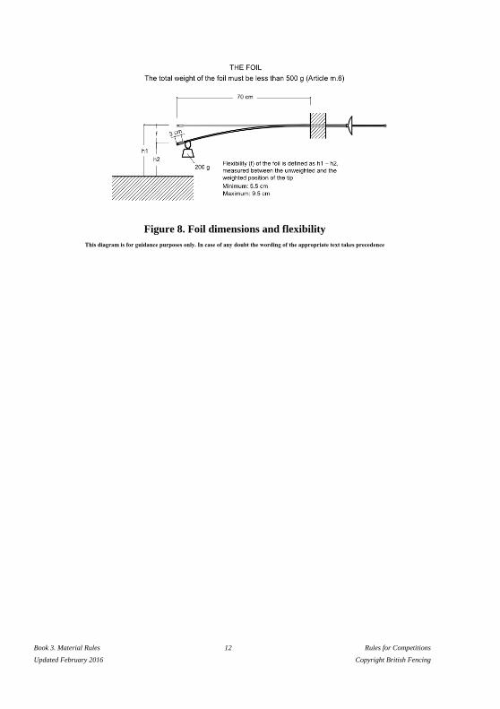
5. The blade should have a flexibility equivalent to a bend of minimum 5.5 cm and
maximum 9.5 cm measured in the following way.
a) The blade is fixed horizontally at a point 70 cm from the extremity of the
button.
b) A 200 g weight (tolerance +/- 1 g) is suspended 3 cm from the extremity of the
button.
c) The bend of the blade is measured at the extremity of the button between the
non-weighted and weighted positions (see Figure 8).
d) The groove in the blade must be uppermost.
6. The blade should be as straight as possible. Any curve of the blade must be
uniform and the maximum bend must in any case be less than one cm; it is only
permitted in the vertical plane and must be near the centre of the blade.
The curve of the blade must be measured as follows:
i) the blade is placed on a flat surface so that the curve is uppermost;
ii) the maximum distance between the flat surface and the blade is measured: this
distance is deemed to be the curve of the blade (cf Fig 8).

Book 3. Material Rules 11 Rules for Competitions
Updated February 2016 Copyright British Fencing
The guard (cf. m.5)
m.9. 1. The guard must be able to pass through a straight cylindrical gauge having a
diameter of 12 cm and a length of 15 cm, the blade being parallel with the axis of
the cylinder.
2. Eccentric mounting is forbidden, that is to say that the blade must pass
through the centre of the guard. The diameter of the guard must be between 9.5
cm and 12 cm.
Book 3. Material Rules 12 Rules for Competitions
Updated February 2016 Copyright British Fencing
Figure 8. Foil dimensions and flexibility
This diagram is for guidance purposes only. In case of any doubt the wording of the appropriate text takes precedence

Book 3. Material Rules 13 Rules for Competitions
Updated February 2016 Copyright British Fencing
Electric wire
m.10. The foil has a single wire, glued in a groove cut the whole length of the blade, which
permanently connects the pointe d’arrêt to the corresponding socket inside the guard.
Pointe d’arrêt
m.11. 1. The diameter of the pointe d’arrêt is between 5.5 mm and 7 mm; the diameter of
the body of the button including its exterior insulation must not be more than 0.3
mm less than that of the pointe d’arrêt.
2. The pointe d’arrêt must be cylindrical; its front surface is flat and perpendicular
to its axis.
Its edge will either be rounded with a radius of 0.5 mm or have a chamfer of 0.5
mm at 45°.
3. The pressure required on the pointe d’arrêt, in order to break the contact and cause
the apparatus to register a hit, must be more than 500 g, that is to say that this
weight must be lifted by the spring of the point. The weight of 500 g supplied by
the Organising Committee may have a tolerance of ± 2 g, i.e. 498–502 g.
4. The course or travel of the pointe d’arrêt required to cause the electrical apparatus
to register a hit, called the lighting stroke, may be infinitesimal: the total travel of
the pointe d’arrêt must not be greater than 1 mm. The gauge used should have a
tolerance of a maximum of +/- 0.05mm.
5. The pointe d’arrêt must be retained in the button in at least two places equidistant
from each other, or by any other method which has been approved by the SEMI
Committee of the FIE.
6. When not depressed the pointe d’arrêt is in contact with the earth circuit of the
foil. When a hit is made, this contact must be broken.
Method of affixing the button
m.12. 1. If the base of the button is not made in one piece with the blade, or if it does not
permit the flattened piece at the tip of the blade to be retained, it must be screwed
onto the end of the blade, which must be cut and threaded for this purpose
respecting the following conditions.
2. Normally, only fixing by metal to metal is allowed. However, fixing by any
insulating material of great mechanical strength may be authorised after approval
by the SEMI Committee of the FIE.
Book 3. Material Rules 14 Rules for Competitions
Updated February 2016 Copyright British Fencing
3. All methods of soldering or brazing or in general any heating which may affect
the temper of the blade are forbidden. Only solder of very easily melted tin, used
with a soldering iron, to prevent the tip from coming loose, is authorised.
4. The end of the blade before cutting the thread must not have a diameter at any
point of less than 3.5 mm, and this without anything being wrapped round it, a
process which is strictly forbidden.
5. The diameter of the core of the thread must not be less than 2.7 mm (thread SI 3.5
x 0.60). The threading must be very tight.
6. The part of the blade on which the button is fixed should be of a length of 7–8
mm entirely covered by the button. It is recommended that only the half of this
length at the extremity of the blade be threaded. For the other half the button will
have a smooth surface of 3.5 mm diameter into which it should take some force for
the corresponding part of the blade to be introduced.
7. When a button made of light alloy is used, instructions should be sought from the
SEMI Committee of the FIE.
8. At the point at which the wire passes into the button, the width of the groove must
not exceed 0.5 mm, and its depth must not exceed 0.6 mm measured on the
diameter of the core of the thread, in order to weaken as little as possible the
section of the blade.
9. Only the members of the SEMI Committee of the FIE or the Directoire
Technique can require the verification of the above points.
The insulation of the button, the blade and the handle
m.13. 1. The body of the button and the foil blade for a length of 15 cm from the button
must be entirely covered with insulating material (insulating tape, gummed paper,
Sellotape, plastic material or varnish).
2. The flange of the sleeve which slides in the base of the point and within which is
fixed the pointe d’arrêt must be of a smaller diameter than the insulated head of the
pointe d’arrêt itself, to obviate an accidental contact being made with the
conductive jacket when a hit is made.

Book 3. Material Rules 15 Rules for Competitions
Updated February 2016 Copyright British Fencing
EPEE
Weight
m.14. The total weight of the épée ready for use is less than 770 g.
Length
m.15. The total maximum length of the épée is 110 cm (cf m.3).
The blade
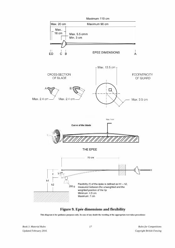
m.16. 1. The blade, which is triangular in section without cutting edges, is made of steel
and must comply with the safety standards described in Annexe A to the Rules.
There are two methods of manufacture (see Figure 9):
— By forging a steel cylinder (Cross-section of blade, A);
— By folding a sheet of steel (Cross-section of blade, B).
2. It should be as straight as possible and mounted with the groove uppermost. Any
curve of the blade must be uniform and the maximum bend must in any case be
less than 1 cm; it is only permitted in the vertical plane and must be near the centre
of the blade.
The curve of the blade must be measured as follows:
i) the blade is placed on a flat surface so that the curve is uppermost;
ii) the maximum distance between the flat surface and the blade is measured: this
distance is deemed to be the curve of the blade (cf Fig 9).
3. The maximum length of the blade is 90 cm.
4. The maximum width of any of the three sides of the blade is 24 mm.
5. The blade should have a flexibility equivalent to a bend of 4.5 cm minimum and 7
cm maximum measured in the following way.
a) The blade is fixed horizontally at a point 70 cm from the extremity of the
button.
b) A 200 g weight (tolerance +/- 1 g) is suspended 3 cm from the extremity of the
button.

Book 3. Material Rules 16 Rules for Competitions
Updated February 2016 Copyright British Fencing
c) The bend of the blade is measured at the extremity of the button between the
non-weighted and weighted positions (see Figure 9).
Book 3. Material Rules 17 Rules for Competitions
Updated February 2016 Copyright British Fencing
Figure 9. Epée dimensions and flexibility
This diagram is for guidance purposes only. In case of any doubt the wording of the appropriate text takes precedence
Book 3. Material Rules 18 Rules for Competitions
Updated February 2016 Copyright British Fencing
The guard (cf. m.5)
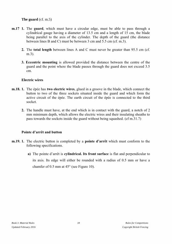
m.17 1. The guard, which must have a circular edge, must be able to pass through a
cylindrical gauge having a diameter of 13.5 cm and a length of 15 cm, the blade
being parallel to the axis of the cylinder. The depth of the guard (the distance
between lines B and C) must be between 3 cm and 5.5 cm (cf. m.3).
2. The total length between lines A and C must never be greater than 95.5 cm (cf.
m.3).
3. Eccentric mounting is allowed provided the distance between the centre of the
guard and the point where the blade passes through the guard does not exceed 3.5
cm.
Electric wires
m.18. 1. The épée has two electric wires, glued in a groove in the blade, which connect the
button to two of the three sockets situated inside the guard and which form the
active circuit of the épée. The earth circuit of the épée is connected to the third
socket.
2. The handle must have, at the end which is in contact with the guard, a notch of 2
mm minimum depth, which allows the electric wires and their insulating sheaths to
pass towards the sockets inside the guard without being squashed. (cf m.31.7)
Pointe d’arrêt and button
m.19. 1. The electric button is completed by a pointe d’arrêt which must conform to the
following specifications.
a) The pointe d’arrêt is cylindrical. Its front surface is flat and perpendicular to
its axis. Its edge will either be rounded with a radius of 0.5 mm or have a
chamfer of 0.5 mm at 45° (see Figure 10).

Book 3. Material Rules 19 Rules for Competitions
Updated February 2016 Copyright British Fencing
Figure 10. Epée: details of the electric button
This diagram is for guidance purposes only. In case of any doubt the wording of the appropriate text takes precedence
b) The diameter of the crown of the pointe d’arrêt is 8 mm with a tolerance of
± 0.05 mm. The diameter of the base must not be less than 7.7 mm.
c) The flange (collar) which guides the pointe d’arrêt as well as the insulating
washer must be sufficiently recessed in relation to the crown (it is
recommended that it be reduced in diameter by 0.3–0.5 mm in relation to the
crown) so that it shall not be possible to cause a hit to be registered merely by
sliding the depressed pointe d’arrêt against the convex surface of the guard
(see Figure 11) (cf. t.67.a).
Figure 11. Epée: details of tip of point
This diagram is for guidance purposes only. In case of any doubt the wording of the appropriate text takes precedence

Book 3. Material Rules 20 Rules for Competitions
Updated February 2016 Copyright British Fencing
2. The pressure required on the pointe d’arrêt in order to complete the circuit in the
épée, and thus cause the apparatus to register a hit, must be more than 750 g, that is
to say that this weight must be lifted by the spring of the point.
3. The weight used to check competitors’ épées on the piste consists of a metal
cylinder drilled part of the way along its axis with a hole parallel to its sides; this
hole, into which is inserted the end of the blade, must have an insulating lining to
prevent its metallic parts coming into contact with the earthed mass of the épée
which might then give a false result to the test.
This weight of 750 g, which is supplied by the Organising Committee, may have a
tolerance of ± 3 g, i.e. 747–753 g.
4. a) The course or travel of the pointe d’arrêt required to complete the circuit in the
épée and thus cause the apparatus to register a hit, called the lighting stroke,
must be greater than 1 mm. The further course which the pointe d’arrêt may
travel must be less than 0.5 mm. (This requirement is just as essential as that
for the lighting stroke). The gauge used should have a tolerance of a maximum
of +/- 0.05mm.
b) To enable a check to be made on the piste, the total course or travel of the
point must be greater than 1.5 mm (cf. t.43). The gauge used should have a
tolerance of a maximum of +/- 0.05mm.
c) Adjusting the lighting stroke by means of screws or any other external fixing
device, once the point has been assembled on the weapon, is forbidden (cf
t.44.3).
d) An external screw or similar fixing device is only allowed if it is actually part
of the assembling of the point.
e) The head of the screw or fixing device must never project beyond the flat top
surface of the point and its housing in the flat surface may not exceed 2 mm in
diameter.
5. The pointe d’arrêt must be retained in the button at at least two points equally
spaced, or by any other system approved by the SEMI Committee of the FIE.
6. When there is a hit, the electrical contact must be established.
Method of affixing the button
m.20. If the base of the button is not made in one piece with the blade, or if it does not
permit the flattened inset piece at the tip of the blade to be retained, the button must be
screwed onto the end of the blade, which must be cut and threaded for this purpose
respecting the following conditions.

Book 3. Material Rules 21 Rules for Competitions
Updated February 2016 Copyright British Fencing
1. Normally, only fixing by metal to metal is allowed. However, fixing by any
insulating material of great mechanical strength may be authorised after approval
by the SEMI Committee of the FIE.
2. Only solder of very easily melted tin, used with a soldering iron, to prevent the tip
from coming loose, is authorised.
3. The end of the blade, before cutting the thread, must not have a diameter at any
point which is less than 4 mm and this without anything being wrapped round it, a
process which is strictly forbidden.
4. a) The diameter of the core of thread at the end of the blade must not be less
than 3.05 mm (thread SI 4.0 x 0.70).
b) The part of the blade on which the button is fixed should be of a length of 7–8
mm entirely covered by the button. It is recommended that only the half of this
length, at the extremity of the blade, be threaded. For the other half the button
will have a smooth surface of 4.0 mm diameter into which it should take some
force for the corresponding part of the blade to be introduced.
5. The groove necessary to enable the wires to enter the button must be cut in such a
way that it weakens as little as possible the section of the blade.
6. Only the members of the SEMI Committee of the FIE or the Directoire
Technique can require the verification of the above points.
Book 3. Material Rules 22 Rules for Competitions
Updated February 2016 Copyright British Fencing
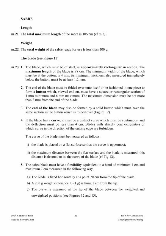
SABRE
Length
m.21. The total maximum length of the sabre is 105 cm (cf m.3).
Weight
m.22. The total weight of the sabre ready for use is less than 500 g.
The blade (see Figure 13)
m.23. 1. The blade, which must be of steel, is approximately rectangular in section. The
maximum length of the blade is 88 cm. The minimum width of the blade, which
must be at the button, is 4 mm; its minimum thickness, also measured immediately
below the button, must be at least 1.2 mm.
2. The end of the blade must be folded over onto itself or be fashioned in one piece to
form a button which, viewed end on, must have a square or rectangular section of
4 mm minimum and 6 mm maximum. The maximum dimension must be not more
than 3 mm from the end of the blade.
3. The end of the blade may also be formed by a solid button which must have the
same section as the button which is folded over (Figure 12).
4. If the blade has a curve, it must be a distinct curve which must be continuous, and
the deflection must be less than 4 cm. Blades with sharply bent extremities or
which curve in the direction of the cutting edge are forbidden.
The curve of the blade must be measured as follows:
i) the blade is placed on a flat surface so that the curve is uppermost;
ii) the maximum distance between the flat surface and the blade is measured: this
distance is deemed to be the curve of the blade (cf Fig 13).
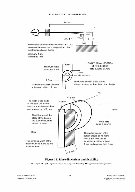
5. The sabre blade must have a flexibility equivalent to a bend of minimum 4 cm and
maximum 7 cm measured in the following way.
a) The blade is fixed horizontally at a point 70 cm from the tip of the blade.
b) A 200 g weight (tolerance +/- 1 g) is hung 1 cm from the tip.
c) The curve is measured at the tip of the blade between the weighted and
unweighted positions (see Figures 12 and 13).
Book 3. Material Rules 23 Rules for Competitions
Updated February 2016 Copyright British Fencing
Figure 12. Sabre dimensions and flexibility
This diagram is for guidance purposes only. In case of any doubt the wording of the appropriate text takes precedence

Book 3. Material Rules 24 Rules for Competitions
Updated February 2016 Copyright British Fencing
The guard (cf. m.5)
m.24. 1. The guard must be full in shape, made in one piece and externally smooth. It must
have a convex form which is continuous, without rim or holes.
2. It must be able to pass through a rectangular gauge measuring 15 cm by 14 cm in
section, with a length of 15 cm, the blade being parallel with the longitudinal axis
of the gauge.
3. Inside the guard there must be a socket into which the bodywire is plugged,
whatever system is used.
4. The two sockets of the bodywire plug must be in direct contact with the body of
the guard, making a closed electrical circuit through the bodywire, the spool and
the cable connecting the spool to the scoring apparatus.
5. The resistance in the weapon must not exceed 1 ohm.
6. The interior of the guard must be completely insulated by means of insulating
paint or a pad.
7. The exterior of the guard must be insulated for 7–8 cm from the pommel.
8. The handle and the pommel must be completely insulated.

Book 3. Material Rules 25 Rules for Competitions
Updated February 2016 Copyright British Fencing
Figure 13. Sabre dimensions (contd.)
This diagram is for guidance purposes only. In case of any doubt the wording of the appropriate text takes precedence

Book 3. Material Rules 26 Rules for Competitions
Updated February 2016 Copyright British Fencing
CHAPTER 2. EQUIPMENT AND CLOTHING
GENERAL CONDITIONS
m.25. The national uniform includes the socks, the breeches and the jacket.
1. Protection: The equipment and clothing must provide the competitor with the
maximum protection compatible with the freedom of movement necessary for
fencing.
2. Safety: It must not be possible for the opponent to be obstructed or injured by
the equipment, nor for it to have either buckles or openings in which the
opponent’s point may be caught up — except accidentally — and thus held or
deflected. The jacket and its collar must be completely buttoned or done up.
3. Characteristics of the clothing
a) Fencers’ clothing must be made of sufficiently robust material and be clean
and in good condition.
b) The material from which the equipment is made must not have a surface
which is smooth enough to cause the pointe d’arrêt, the button or the
opponent’s hit to glance off (cf. m.30).
c) Clothing must be made entirely in cloth able to resist a pressure of 800
Newtons. Very particular attention must be paid to the way the seams under
the armpits, if there are any, are made. An under-garment consisting of a
protective under-plastron covering the vital upper areas of the body (following
the design given in Annexe A to these Rules, ‘Safety norms for
manufacturers’) resistant to 800 Newtons is also obligatory.
d) Fencers’ clothing may be of different colours, apart from black.
e) There shall be only one national uniform per country with the exception that
the manufacturers' marks and sponsors' logos may be different.
f) Logos (national strips) worn on the national clothing must be approved by the
FIE Executive Committee at least 30 days before they are used for the first
time in an official FIE competition; they are then published on the FIE website.
g) For the following events, the wearing of national strips (logos) is compulsory
on both legs, optional on the arm(s) (cf. t.45.4). All the logos worn by any one
fencer must be identical.
i) Senior Junior and Cadet World Championships: all bouts, whether in a
pool, in the direct elimination or during a team match;
Book 3. Material Rules 27 Rules for Competitions
Updated February 2016 Copyright British Fencing
ii) Individual Senior World Cup competitions and in individual Senior
Zonal Championships: all bouts, whether in a pool or in the direct
elimination bouts;
iii) Teams: Senior World Cup team competitions and Senior Zonal
Championships: all bouts in every match.
They must be identical for all fencers of the same federation for the
competitions i) and iii) above.
h) The name of the fencer must be displayed on the back of the jacket, with the
abbreviation of the national federation below it, at the level of the shoulder
blades. They must be printed directly onto the jacket or onto a cloth entirely
sewn onto the jacket. The letters must be in dark blue, in capitals, between 8
cm and 10 cm high, and between 1 cm and 1.5 cm wide, according to the
length of the name.
4. Jacket
a) At all weapons, for men and ladies, the lower edge of the jacket must overlap
the breeches by at least 10 cm when the fencer is in the on-guard position (cf.
m.28, m.34).
b) The jacket must include a lining making a double thickness of material for the
sleeve down to the elbow of the sword arm and covering the flank up to the
region of the armpit. At épée the fencer is required to wear a regulation jacket,
which covers the whole of the surface of the trunk.
c) The use of a breast/chest protector (made of metal or some rigid material) is
compulsory for women and optional for men. At foil, this breast/chest
protector must be worn below the protective plastron.
The entire outside of the chest protector (the side facing the opponent) must be
covered with a soft material. (The material can be attached to the current
plastic models or incorporated into the manufacture of new chest protectors.)
The hardness of the outside of the material must be 20-30% hardness. This is
the typical hardness of wet suit material for scuba diving (neoprene). This
measure will be obligatory for the 2015/2016 season: the SEMI commission is
to supply the specifications and testing procedures.
5. Breeches
a) The breeches must be fastened below the knees.
b) With breeches, the fencer must wear socks which cover the legs right up to the
breeches. These socks must be held up in such a way that they cannot fall
down.

Book 3. Material Rules 28 Rules for Competitions
Updated February 2016 Copyright British Fencing
c) The fencer is permitted to wear socks with a 10cm turn-over showing the
colours of his national team.
6. Glove
At all weapons, the gauntlet of the glove must, in all circumstances, fully
cover approximately half the forearm of the competitor’s sword arm to prevent
the opponent’s blade entering the sleeve of the jacket.
7. Mask
a) The mask must be made with meshes (space between the wires) of maximum
2.1 mm and from wires with a minimum gauge of 1 mm diameter. The mask
must include two different safety systems at the rear.
b) Masks, at all weapons, must be made in accordance with the safety standards
described in Annexe A to these Rules and must carry the quality label specified
in those standards.
c) When the checks are carried out the person responsible for them may, if in
doubt, ensure that the mesh of the mask, both at the front and at the sides, is
able to withstand, without permanent deformation, the introduction of a conical
instrument, the angle of the surface of the cone being at 4° to the axis and at a
pressure of 12 kg.
d) A mask which does not comply with the safety requirements laid down in this
article will be rendered visibly unusable by the weapon checking personnel or
the Referee in the presence of the person who presented the mask to the
weapon check or the team captain of the fencer concerned.
e) The bib of the mask must be made with cloth resistant to 1600 Newtons.
f) The mask must contain a two different safety systems at the rear of the mask,
with the two ends of the straps of the systems firmly affixed to the two sides of
the mask. These straps may be elastic or of any other material that may be
approved by the S.E.M.I. Commission.
Please refer to the examples in the drawings below:

Book 3. Material Rules 29 Rules for Competitions
Updated February 2016 Copyright British Fencing
These images are only provided for information. When in doubt, the wording of the
relevant text prevails.
RULES SPECIFIC TO FOIL
Glove (cf. m.25)
m.26. The glove may be slightly padded.
Mask (cf. m.25)
m.27. 1. The mesh of the mask must not extend below the chin. It must be insulated
internally and externally by a plastic material resistant to impact.
2. The part of the bib that is beneath a horizontal line 1.5 - 2 cm below the chin, must
be entirely covered with a material that has the same conductive characteristics as
the conductive jacket.
3. Means of connection: the electrical contact between the conductive jacket and the
bib of the mask must be ensured by means of a white-coloured or clear covered
wire with two crocodile clips. The wire must be attached to the bib of the mask
with one crocodile clip and to the jacket with the other. This wire must be between
30cm and 40cm long.
In the case of a coiled wire, the maximum length of the free cable must not exceed
25cm with a tolerance of +/- 5cm.
3. Means of connection: the electrical contact between the conductive jacket and the
bib of the mask must be ensured by means of a white coloured or clear covered
wire with two crocodile clips. The wire must be attached to the bib of the mask
with one crocodile clip and to the jacket with the other. This wire must be between
30cm and 40cm long.

Book 3. Material Rules 30 Rules for Competitions
Updated February 2016 Copyright British Fencing
A coiled mask wire is not allowed.
Application: starting season 2016-2017.
Conductive jacket and conductive T-shirt
m.28. 1. The conductive surface of the conductive over-jacket which is worn over the
protective jacket must cover the valid target of the fencer (cf. t.47) entirely and
without omission when in the on-guard position. The jacket must have a
conductive flap, minimum 2 cm by 3 cm, near the middle of the back, just below
the collar, to which the crocodile clip from the mask can be attached
2. Whatever the means of fastening used, the conductive material must cover a
sufficient area to ensure that it covers the valid target in all positions of the fencer.
The overlap must always be on the sword-arm side.
3. The interior of conductive jackets must be electrically insulated by a lining or by
an adequate treatment of the conductive lamé material.
4. The conductive collar must have a minimum height of 3 cm and the foil
conductive jacket must have a conductive flap, minimum 2cm by 3 cm, near the
middle of the back, just below the collar, to which the crocodile clip from the mask
can be attached.
5. The lamé material used must be of conductive thread in both warp and weft. As
regards electrical conductibility it must conform to the following requirements.
a) The electrical resistance measured between any two points of the lamé
material must not be greater than 5 ohms. The resistance will be measured by
using a 500g conductive metal weight which has a hemispherical end with a
radius of 4 mm. This weight, placed on this end and moved about on the lamé,
must maintain continuous contact with a maximum resistance of 5 ohms.
b) In no circumstances must the use of a conductive jacket be allowed if it has
holes in it, or patches of oxidation or other defects which may prevent the
registration of a valid hit.
c) A conductive jacket which is considered to be unusable will be so marked
with a very visible coloured paint by a member of the SEMI Committee of the
FIE.

Book 3. Material Rules 31 Rules for Competitions
Updated February 2016 Copyright British Fencing
6. The conductive jacket must be so made that when it is laid flat there is a straight
line between the point of junction of the lines of the groin and the two points
corresponding to the tops of the hip bones (ilium).
7. The band of non-conductive material passing between the legs must be at least 3
cm wide (see Figure 14).
8. For compliance of the T-shirt’s electrical resistance with a wireless manufacturer’s
requirements, the maximum electrical resistance:
a) between any two points of the electrically conductive belt on the T-shirt
(including both flaps for crocodile clip connection) should be not more than 15
Ohms;
b) between any two points on the electrically conductive fabric-belt portion of the
T-shirt (including both flaps for the crocodile-clip connection) and any point of
the electrically conductive fabric on the sleeves or on the neck, should be not
more than 50 Ohms;
c) these checks must be carried out by a wireless equipment manufacturer.
Book 3. Material Rules 32 Rules for Competitions
Updated February 2016 Copyright British Fencing
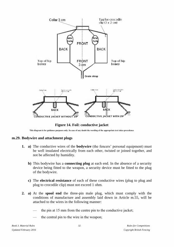
Figure 14. Foil: conductive jacket
This diagram is for guidance purposes only. In case of any doubt the wording of the appropriate text takes precedence
m.29. Bodywire and attachment plugs
1. a) The conductive wires of the bodywire (the fencers’ personal equipment) must
be well insulated electrically from each other, twisted or joined together, and
not be affected by humidity.
b) This bodywire has a connecting plug at each end. In the absence of a security
device being fitted to the weapon, a security device must be fitted to the plug
of the bodywire.
c) The electrical resistance of each of these conductive wires (plug to plug and
plug to crocodile clip) must not exceed 1 ohm.
2. a) At the spool end the three-pin male plug, which must comply with the
conditions of manufacture and assembly laid down in Article m.55, will be
attached to the wires in the following manner:
— the pin at 15 mm from the centre pin to the conductive jacket;
— the central pin to the wire in the weapon;

Book 3. Material Rules 33 Rules for Competitions
Updated February 2016 Copyright British Fencing
— the pin at 20 mm from the centre pin to the foil earth circuit or the
conductive piste.
b) The wire which joins the rear connection of the bodywire to the conductive
jacket by a crocodile clip must be separate for at least 40 cm. This wire must
be soldered to the crocodile clip and this soldering must not be covered by any
insulation or any material whatsoever. However, any method of fixing which
presents the same guarantees as soldering may be used, provided it has been
accepted by the SEMI Committee.
c) The crocodile clip must be robust and ensure perfect contact with the
conductive jacket. Its width at the point of contact must be at least 10 mm; the
inside of the clip must leave a free space at least 8 mm long by 3 mm high. It
must be clipped onto the back of the conductive jacket on the sword-arm side.
3. a) At the end nearest the foil, inside the guard, any method of attachment is
allowed but the method adopted must always conform to the specification laid
down in Article m.5.
b) In addition, the pins of the plug must in no circumstances be able to touch the
metal part of the guard.
c) The wire from the point will be protected by an insulated sheath from the
place where it enters the guard right up to the insulated connection on the plug
socket. Under no circumstances may the non-insulated wire extend beyond this
insulated plug connection (cf. m.5, m.9).

Book 3. Material Rules 34 Rules for Competitions
Updated February 2016 Copyright British Fencing
RULES SPECIFIC TO EPEE
Mask
m.30. 1. The mask must not be covered, in whole or in part, by material which can cause
the point to glance off (cf. m.25).
2. The mask must be so shaped that the bib reaches below the prominences of the
collar bones (clavicles).
Bodywire
m.31. 1. a) The conductive wires of the bodywire (the fencers’ personal equipment) must
be well insulated from each other, insensitive to humidity, and either joined or
twisted together.
b) The maximum electrical resistance allowed for each of these conductive
wires from plug to plug is 1 ohm.
2. The bodywire has a connecting plug at each end. In the absence of a security
device being fitted to the weapon, a security device must be fitted to the plug of the
bodywire.
3. At the spool end, a three-pin male plug is connected to the wire as follows:
a) the pin 15 mm from the centre pin to whichever wire is most directly
connected to the pointe d’arrêt;
b) the centre pin to the other wire on the épée;
c) the pin 20 mm from the centre pin to the épée’s earth circuit and to the
conductive piste.
4. This plug must conform to the conditions of manufacture and mounting specified
in Article m.55.
5. Inside the guard the choice of system is free but the system chosen must comply
with the conditions of Article m.5.
6. In addition, the pins of the plug must not on any account permit contact with the
metal of the guard.
7. The two wires coming from the tip must be protected by two insulating sheaths,
one for each wire, from the point where they enter the guard right up to the two
insulated connections on the plug socket. In no case may uninsulated wires extend
beyond the plug connections (cf. m.5, m.9).

Book 3. Material Rules 35 Rules for Competitions
Updated February 2016 Copyright British Fencing
RULES SPECIFIC TO SABRE
Mask
m.32. 1. The metal mesh of the mask must not be insulated and must ensure electrical
conductivity.
2. The bib and any trim must be entirely covered with conductive material with the
same electrical characteristics as the conductive jacket.
3. The trim may also be made of conductive material.
4. The electrical contact between the conductive jacket and the mask must be
ensured by means of a wire and one or two crocodile clips. In the case of a coiled
cable, the maximum length of the free cable must not exceed 25 cm in length, with
a tolerance of ± 5 cm.
4. The electrical contact between the conductive jacket and the mask must be
ensured by means of a white coloured or clear covered wire with one or two
crocodile clips. The wire must be attached to the mask with one crocodile clip or
by soldering and to the jacket with a crocodile clip. This wire must be between
30cm and 40cm long. A coiled mask wire is not allowed.
Application: starting season 2016-2017.
5. The electrical resistance between the crocodile clip and any point on the mask
must be less than 5 ohms. The crocodile clip(s), the design and size of which must
conform to the conditions laid down in Article m.29.2(c), must be soldered to the
end(s) of the wire. In addition, the electrical resistance in this wire (between
crocodile clip and crocodile clip or crocodile clip and soldering) must not exceed 1
ohm. The wire must be white-coloured or clear.
Glove
m.33. 1. The material of the fencing glove must have a level of protection of 800N on the
areas shown in the diagram below, the seams a minimum strength of 200N and cuff
a level of protection of 350N. The conductive material, which can be removable or
fixed, must cover all of the gauntlet of the glove down to below the external cubital
styloid (small prominent bone of the wrist), both when the fencer is in the ‘on-
guard’ position and when the sword arm is straight. Inside the glove there must be

Book 3. Material Rules 36 Rules for Competitions
Updated February 2016 Copyright British Fencing
fixed the FIE quality label, granted after the homologation procedure, with the year
of manufacture and stating 800N.
This diagram is for guidance purposes only. In case of any doubt the wording of the appropriate text takes precedence
2. The conductive material must be turned over into the inside of the gauntlet to a
depth of at least 5 cm.
3. In order to guarantee a good contact with the sleeve of the conductive jacket, it is
necessary to use an elastic band, a popper button or any system which will
guarantee conductivity and which has been approved by the SEMI Committee.
When a conductive overlay is worn, the overlay must contain a device which fixes
the position of the overlay on the arm so that its position on the arm cannot be
changed during the bout.
4. The conductive tissue (lamé) must satisfy the specified control conditions (cf
m.28.5)
Conductive jacket and conductive t-shirt
m.34. 1. The fencer must wear, over his jacket, a conductive over-jacket, the conductive
surface of which must cover entirely and without omission the valid surface of the
body above a horizontal line which, when the fencer is on guard, joins, round the
fencer’s trunk, the tops of the two hip bones. At wireless sabre the fencer must
wear a conductive t-shirt. The conductive part is made of a conductive fabric: the
maximum electrical resistance between any two points of the electrically
conductive t-shirt fabric (including both flaps for crocodile clip connections) must
be not more than 15 Ohms. These checks must be carried out by a wireless
equipment manufacturer.
2. The conductive surface must cover the arms as far as the wrists. The jacket must
have a collar which is at least 3 cm high. The jacket must have a conductive flap,
minimum 2 cm x 3 cm in the middle of the back, just below the collar, to which the
crocodile clip from the mask can be attached.

Book 3. Material Rules 37 Rules for Competitions
Updated February 2016 Copyright British Fencing
3. Whatever means of fastening is used, the conductive material must be ample
enough to guarantee covering the valid target area in any position.
4. The conductive material (lamé) must satisfy the conditions laid down for testing
(cf. m.28).
5. The sleeves of the conductive jacket must be fixed at the wrist by means of an
elastic band. There must be a strap passing between the fencer’s legs to keep the
jacket in place (see Figure 15).
Figure 15. Sabre: conductive jacket
This diagram is for guidance purposes only. In case of any doubt the wording of the appropriate text takes precedence
Bodywire and plugs
m.35. The fencer must use the bodywire specified for foil, plugged into the guard plug
socket by means of any system which conforms with the conditions for manufacture
and assembly laid down in Articles m.5, m.29 and m.55.
Book 3. Material Rules 38 Rules for Competitions
Updated February 2016 Copyright British Fencing
CHAPTER 3. CHECKING OF MATERIAL
COMPETENCE
m.36. 1. The checking of the electrical material used by the organisers for the World
Championships (Open, Junior and Cadet) and the fencing competitions of the
Olympic Games, as well as the checking of the fencers’ equipment, must be
supervised by the SEMI Committee.
2. To carry out this supervision, three members of the above-mentioned Committee
must be appointed and put in charge of this work. However, when the organising
country possesses somebody competent, recognised as such by the SEMI, two
members of the above Committee will be appointed.
3. The delegates of the SEMI Committee of the FIE have the right at any time to
seize a weapon, a bodywire, a conductive jacket or any item of equipment or
clothing for examination.
CHECKING OF FENCERS’ EQUIPMENT
m.37. 1. In all official FIE competitions the fencers are responsible for their equipment
(including weapons and clothes) at the moment they present themselves on the
piste.
2. In particular blades, masks and clothing must all carry the label of guarantee
specified in the safety standards annexed to these Rules.
3. The forms of checking laid down by these Rules are only intended to help
organisers who must apply the Rules and fencers who must always respect these
Rules. These checks can, therefore, in no way absolve any fencers who break the
Rules from responsibility.
Presentation of equipment to the Weapon Checking Centre
m.38. 1. Fencers are obliged to present themselves at the Weapon Checking Centre, at the
time advised in the timetable of each official competition of the FIE, with the
equipment they intend to use during the event in question. The number of articles
handed to the Checking Centre is limited to four weapons, three bodywires, two
conductive jackets, two masks and three mask-to-jacket leads per fencer.
2. Each competitor must submit his weapons in a fencing bag at the Weapon
Checking Centre reception. An inventory of the equipment is made by an
organising official and a label is put on the bag, indicating the name of the country
of the competitor. The bags are stored in the order in which they arrive, and are
checked in the same order.
Book 3. Material Rules 39 Rules for Competitions
Updated February 2016 Copyright British Fencing
3. Provision should be made for weapons and clothing to be submitted on the
morning of the day before the competition. Having been checked, the material
will be returned to the delegations at the end of the day.
Weapons, equipment and clothing presented to the Checking Centre after 5 p.m. on
the day before each event may be refused.
4. Each head of delegation must indicate where he can be contacted should a serious
fault be detected while the equipment belonging to his fencers is being checked.
5. If a weapon is found to be defective at the first check a form is attached indicating
the fault: e.g. the length of the blade, the insulation, the spring of the point, cutting
edges, etc. This form is completed at the second check. However, when a weapon
is rejected, it must go through the entire cycle again.
m.39. 1. If material or equipment presented to the Checking Centre appears to have been
assembled in such a way that the fencer can control at will the registering of hits or
the malfunctioning of the judging apparatus, the representative of the SEMI
Committee may, after the examination of the irregular items, require a penalty
against the person who submitted them.
2. The fencers or the team captain can only insist on the return of the equipment
which has been checked one hour before the start of the event.
3. Any repairs to equipment rejected during the checking can be carried out in the
repair workshop. Repaired equipment will, however, only be tested again after the
first set of checks of the other fencers’ equipment has been completed.
Body responsible for checks
m.40. 1. The Executive Committee of the FIE will appoint the member(s) of the SEMI
Committee to be responsible for the checking of weapons, clothing and equipment
of the fencers at the fencing competitions of the Olympic Games and for the World
Championships.
2. For other official FIE competitions the Organising Committee will appoint one or
more persons to be responsible for this checking.
m.41. The items of equipment which have been thus checked will be distinctively marked.
A fencer must not, on pain of penalties (cf. t.120), use any equipment which does not
bear this check mark.

Book 3. Material Rules 40 Rules for Competitions
Updated February 2016 Copyright British Fencing
Personnel and equipment required for checking
m.42. 1. In order to allow those carrying out the checking to fulfil their task, the organisers
are required to make available the equipment (gauges, weights, scales, electrical
measuring machines, etc.) and the personnel necessary to carry out the work.
2. The Organising Committee must provide the FIE technical delegates responsible
for checking the weapons and equipment with at least the following apparatus:
a) Two gauges allowing the lengths of blades and the depths and diameters of the
guards at all weapons to be measured quickly.
b) Devices for measuring the flexibility of blades and the resistance of the mesh
of masks.
c) An electrical checking device to check quickly that the electrical resistance of
the point is not too high, and that the bodywire and the weapon are correctly
assembled. Devices enabling these measurements to be taken easily are, in
fact, commercially available.
d) Weights of 750 g and 500 g to test the springs of the points in épée and foil, in
the workshop and at each piste.
e) A device allowing the lighting stroke and residual travel of épée points to be
accurately measured, in the workshop and at each piste.
f) Labels to indicate that a weapon has been checked and that it satisfies the
regulation, or has been rejected.
g) In the world championships and Olympic Games the control of blades by
Foucault current is mandatory.
h) The organisers must provide a special stamp to be affixed to each conductive
jacket to enable the referees to verify that its resistance in ohms has been
checked by the technical delegates of the FIE. Nevertheless, this compulsory
checking mark is not sufficient to justify the use of the jacket. In effect, it is the
task of the Referee to check, before each event, that the conductive jacket,
having been checked and marked, entirely covers the valid target area, and
accordingly to make the final decision whether it may be used.
i) A special ink or paint must be provided to mark the guards, blades and points
of weapons which have been checked. Nevertheless, those responsible may use
other methods to mark the weapons and conductive jackets.
Book 3. Material Rules 41 Rules for Competitions
Updated February 2016 Copyright British Fencing
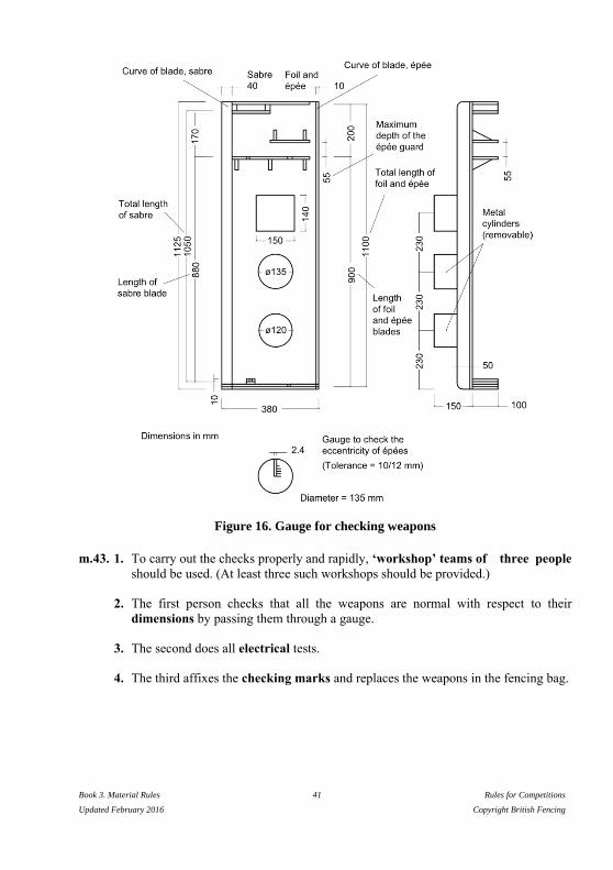
Figure 16. Gauge for checking weapons
m.43. 1. To carry out the checks properly and rapidly, ‘workshop’ teams of three people
should be used. (At least three such workshops should be provided.)
2. The first person checks that all the weapons are normal with respect to their
dimensions by passing them through a gauge.
3. The second does all electrical tests.
4. The third affixes the checking marks and replaces the weapons in the fencing bag.

Book 3. Material Rules 42 Rules for Competitions
Updated February 2016 Copyright British Fencing
PART 2. FITTINGS AND MATERIAL
PROVIDED BY THE ORGANISERS
Introduction
m.44. 1. All electrical judging equipment includes, in addition to the equipment provided
by the fencers themselves, the material provided by the organisers of a
competition, which is:
2. The central judging apparatus, with extension lamps (cf. m.51, m.59, Annexe B);
3. The spools, with cables and connections, or cables suspended overhead (cf. m.55);
4. The conductive piste which neutralises hits made on the ground (cf. m.57);
5. The source of electrical current (accumulators) (cf. m.58);
6. For finals of official competitions of the FIE, a clock which counts down the time
and which can be linked to the apparatus which controls the audible signal and the
electrical registering of hits (cf. m.51, Annexe B).
7. The wireless apparatus is optional at the Veteran World Championships.

Book 3. Material Rules 43 Rules for Competitions
Updated February 2016 Copyright British Fencing
CHAPTER 1. SCORING APPARATUS
Authorised designs
m.45. Only electrical apparatus designed with wires connecting the fencers to the central
apparatus and registering hits by light signals with auxiliary sound signals are
authorised, except for apparatus without wires using encoded waves authorised by the
SEMI. This excludes other apparatus based on wireless waves and those which
register sound signals only.
Approval of designs of apparatus
m.46. 1. Judging apparatus for use in a World Championship or the Olympic Games
must have been approved by the SEMI Committee of the FIE.
2. In order to obtain this approval, the apparatus which it is proposed to use must be
submitted complete, with spools, connections, etc., for an examination by the said
Committee, at a place and on a date to be agreed with the Committee, at least six
months before the date of the competition.
3. The apparatus must be accompanied by a detailed drawing showing its
construction.
m.47. Approval is given for the use of the apparatus in one specific official competition
only. The SEMI Committee is willing, as far as it is able, and without charge, to
examine prototypes of apparatus submitted by constructors even if the use of such
apparatus is not envisaged for an imminent official competition.
m.48. 1. Approval is given for only one established design of apparatus which conforms to
the drawing submitted, and is not given as a general approval for all the products
made by any manufacturer. The latter may state in their publicity only the fact that
the design of apparatus which they offer for sale has been used at a specific official
competition (if this in fact is the case); but they themselves must guarantee that the
apparatus conforms to the design for which approval was given.
2. Every approved apparatus must carry, on its base, a metallic plate identifying its
specific characteristics: manufacturer, year of manufacture, model, technical
information, etc.
m.49. The approval of an apparatus by the SEMI Committee as well as its acceptance
implies no guarantee against possible faults of construction, or against its use with a
source of electrical current other than accumulators (cf. m.58).
m.50. All expenses incurred by the SEMI Committee for the examination of apparatus are
the responsibility of the persons submitting the apparatus.
Book 3. Material Rules 44 Rules for Competitions
Updated February 2016 Copyright British Fencing
Requirements for all electrical equipment (cf. Annexe B)
m.51. 1. A hit made on the conductive piste or on the metallic parts of the weapon must
not be registered by the apparatus, nor may it prevent the registering of a hit made
simultaneously by the opponent. At foil a hit made on a part of the foil may register
if an uninsulated part of the weapon of the fencer is in contact with his conductive
jacket.
2. The apparatus must not have any device whereby anyone other than the person
detailed to supervise it can interrupt its working during a bout.
3. Hits are registered by light signals. The signal lamps must be placed on the top of
the apparatus, in order that they may be visible to the Referee, the competitors and
the superintendent of the apparatus. They must be so positioned that they show
clearly from which side the hit was made. It must be possible to attach extension
lamps to the exterior of the apparatus, in order to increase the visibility of the
signals.
4. Once the signal lamps are alight, they must so remain until the apparatus is reset,
without having any tendency to go out or flicker either when subsequent hits are
made or if the apparatus is subjected to vibrations.
5. The visual signals must be accompanied by audible signals (cf. Annexe B).
6. The resetting switches must be placed either on top of or on the front part of the
apparatus.
7. a) For official competitions of the FIE, the source of power must always be
accumulators. The wiring of the box to be powered in this way must be
designed so that it is impossible for the box to become connected by mistake to
the mains supply.
b) All fencing salles, clubs, etc., and the organisers of training sessions or
competitions involving weapons using electrical equipment, may use the
current supplied by the mains on condition that they adhere strictly to the
technical standards laid down on the subject by their countries and
international communities.
8. a) During the last 10 seconds of each period in an individual bout and of each
bout in a team match, the clock must show: the time to a tenth of second when
the scoring apparatus is running and to a hundredth of second when the scoring
apparatus is stopped. The timer should be provided with a remote start/stop
device (see Annex B for technical specifications). [Application: season
2015/2016 for the World Championships and the Olympic Games only -
season 2016/2017 for the World Cup competitions (Junior and Senior), the
Grand Prix and the Zonal Championships (Junior and Senior).] If the clock is
not incorporated in the electrical judging apparatus, the apparatus must have a
Book 3. Material Rules 45 Rules for Competitions
Updated February 2016 Copyright British Fencing
system for linking in an external clock. This clock must be powered by
electricity from a 12 volt accumulator. A disconnection of the wiring which
links the clock to the apparatus must cause, simultaneously, the blocking of the
apparatus which registers hits, in a manner which preserves what it has
registered up to that point, and the stopping of the clock.
b) To allow the apparatus to be used when it is not connected to the clock, there
must be a switch in the interior of the apparatus which can change its operating
mode (cf. t.32, m.44).
9. For the finals of official competitions of the FIE, the clock must be equipped with
a system which connects it to some external extension clocks displaying large
luminous numbers, and with another system for the connection of the audible
signal. These two connection systems must be separated from the circuits situated
inside the central judging apparatus by means of opto-couplers (cf. t.32, m.44).
10. When the cable connecting the audible-signal apparatus to the clock is
disconnected, the audible-signal apparatus must emit a sound of between 80 and
100 decibels (measured at the centre line of the piste) lasting between 2 and 3
seconds, but the central judging apparatus must not be blocked and the clock must
not be stopped (cf. t.32, m.44, m.51/9).
Number and quality of judging apparatuses
m.52. 1. For official FIE competitions, the organising committee must provide a minimum
number of electrical judging apparatuses equal to the number of pistes plus at
least two spares. All the apparatuses must be in perfect working order, and of a
type approved for the World Championships.
2. As soon as a member federation is selected to organise an official FIE
competition, it would do well to contact the President of the SEMI Committee
immediately in order to obtain the names of manufacturers whose electrical
apparatus is accepted by the Committee.
3. The Organising Committee usually prefers combined apparatus, which can be used
for all three weapons. The Organising Committee must choose a manufacturer who
will provide good quality equipment for the smooth technical running of
competitions; this equipment must be approved by the SEMI Committee.
4. For official FIE competitions, it is compulsory that the apparatus be powered by
accumulators without any connection to the main electrical supply.
Checking of apparatuses
m.53. 1. Having chosen the manufacturer with which it wants to deal, the Organising
Committee of a World Championship immediately advises the President of the

Book 3. Material Rules 46 Rules for Competitions
Updated February 2016 Copyright British Fencing
SEMI Committee of the FIE who in turn contacts this firm to obtain, as soon as
possible, a prototype of the desired model.
The control of the fencing apparatuses must be done before the competition using a
checking device that is able to verify that the fencing apparatuses fulfil all
requirements related to reaction times and electrical resistances.
2. The report on the checking of the apparatus is always presented to the
manufacturer by the President of the Committee within one month of the apparatus
being received.
3. There are then two possibilities:
a) The proposed apparatus is accepted by the Committee, in which case the other
apparatuses can be manufactured like the prototype.
b) The apparatus does not conform to the requirements, in which case it must be
modified and re-submitted to the Committee for a new examination.
4. When all the apparatuses are ready and before they are sent out, the President of
the SEMI Committee must be notified, so that he can document the checking of
the apparatuses before they leave the factory. Each apparatus comes with a test
report giving the different specifications concerning the registering time in
milliseconds and the resistance in ohms of the external circuits before registering a
non-valid hit.
The person in charge of verification ticks off every apparatus and makes a note of
its number.
m.54. 1. Before every World Championship or Olympic Games, a delegate of the SEMI
Committee must check the proper working of the apparatuses to be used and
that they conform to the type registered. This is independent of the registration of
the type of apparatus mentioned above (cf. m.52).
2. The apparatuses must be made available to this delegate at least 48 hours before
the beginning of the competition.

Book 3. Material Rules 47 Rules for Competitions
Updated February 2016 Copyright British Fencing
CHAPTER 2. SPOOLS, CABLES AND
THEIR CONNECTIONS
m.55. 1. The maximum electrical resistance of each wire of the spool, measured from
socket to socket, must be 3 ohms.
2. There must be no interruption of electrical contact even when the spool is being
rotated at full speed. To ensure this the contact rings must have double brushes.
The wire connected to the earth circuit of the weapon will be connected to the
frame of the spool.
3. The spools must allow 20 m of cable to be unwound without straining the springs.
4. The socket which terminates the spool cable, and is designed to receive the plug of
the bodywire at the fencer’s back, must include a safety device which fulfils the
following requirements:
— that it is impossible to use it unless the plug is correctly put in;
— that it is impossible for it to become separated during the bout;
— that it is possible for the competitor to verify that the two foregoing
requirements are satisfied.
5. The resistance of each of the three wires in the connecting cables must not exceed
2.5 ohms.
6. The plugs used to connect the bodywire to the spool wire and the connecting
cables to the spools and to the apparatus must have three pins of 4 mm diameter
arranged in a straight line. The outer pins must be spaced 15 and 20 mm
respectively from the centre pin. The bodywire and the connecting cables have
plugs, the spool wires and the central electrical apparatus have sockets to them.
7. The use of suspended cables instead of spools is permitted, provided that the
conditions already mentioned are satisfied.
m.56. 1. The organisers must ensure that the spools have cables of at least 20 m in length
so that they do not get ripped out in the event of a flèche made at the end of the
piste.
2. It is desirable for the spools to be placed close to the pistes, but outside them so
that fencers do not trip over them.
3. The cables connecting the spools to the apparatus should be of the three core type
and be covered with rubber to protect them from humidity and blows.
4. Conductive pistes should be earthed at the centre of the piste.
Book 3. Material Rules 48 Rules for Competitions
Updated February 2016 Copyright British Fencing
5. Those in charge of checking equipment during competitions must have a simple
and practical device at their disposal to allow them to check quickly that there are
no breaks or short-circuits in the three wires of the spools.
Book 3. Material Rules 49 Rules for Competitions
Updated February 2016 Copyright British Fencing
CHAPTER 3. CONDUCTIVE PISTES
m.57. 1. The conductive piste must be made from metal, metallic mesh or some substance
that is conductive. The resistance of the piste, from one end to the other, must not
exceed 5 ohms.
2. The conductive piste must cover the whole of the length and breadth of the piste
including its extensions, in order to neutralise floor hits.
3. a) When the piste is mounted on a platform the conductive piste must cover the
whole width of the platform.
b) The platform must not exceed 50 cm in height, and must be wider than the
fencing piste itself by at least 25 cm on each side. Each end of the podium
must be equipped with a gentle slope right down to ground level.
4. Because the amount of wire which the spools can carry is limited, the conductive
piste is designed for use on a piste 14 m long; an extension of 1.50–2 m is added at
each end of the piste to allow the fencer crossing the rear limits of the piste to retire
on an even and unvarying surface. The conductive piste must therefore have a
length of 17–18 m.
5. a) It is preferable to lay the conductive piste on a wooden base with some
flexible material between. It must be provided with some device which enables
it to be kept well stretched.
b) The wooden bases are 12–15 cm above ground level. Their sides must not be
sloping.
c) It is preferable to have a metal strip, screwed down if possible, which will
keep down the edges of the conductive piste along the entire length of the base
on both sides.
d) Pistes made of metallic mesh must never be placed directly on a floor of
reinforced concrete or tiles.
6. The paint used to draw the lines on the conductive piste must not prevent its
electrical conductibility, so that a hit made on it at a point where a line occurs is
also neutralised.
7. The organisers must have equipment for the immediate repair of the piste
available on the spot.
8. There must be no roller or any sort of obstacle at the ends of the conductive pistes
which could prevent the fencers from retreating normally.

Book 3. Material Rules 50 Rules for Competitions
Updated February 2016 Copyright British Fencing
9. Pistes used in the World Championships and in the Olympic Games must be tested
before competition by SEMI Commission Delegates using the Slip-Meter.
10. The specifications of the Slip-Meter must fulfil the specifications defined in the
homologation manual.
Book 3. Material Rules 51 Rules for Competitions
Updated February 2016 Copyright British Fencing
CHAPTER 4. SOURCE OF ELECTRICAL CURRENT
m.58. 1. The apparatus must be based on a 12 volt supply (± 5%) or, if the sources of
current for each side of the apparatus are separate, on 2 x 12 volts or 2 x 6 volts.
(The separation of the supply for each side of the apparatus is recommended
because it can simplify a number of problems met in the construction of apparatus
for foil.)
2. The apparatus may include warning lights to indicate that it is switched on. Such
lights should be colourless.
3. If the apparatus is constructed to operate with dry batteries, it must be equipped
with a voltmeter or some other device enabling the power in the batteries to be
checked at any moment. However, the apparatus must always be equipped with a
socket, as described above, to allow it to be powered by accumulators.
4. Generally, there should be two batteries available per apparatus: 12 volt car
batteries are used, of 60 or 90 amps/hour.
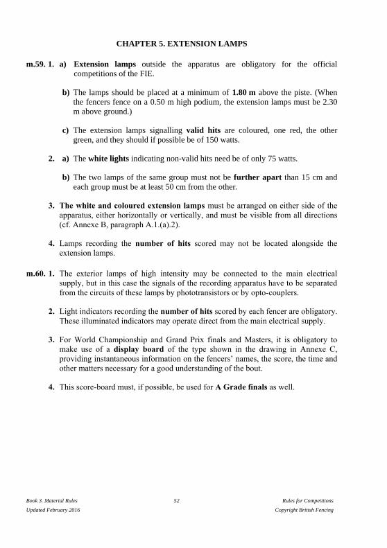
Book 3. Material Rules 52 Rules for Competitions
Updated February 2016 Copyright British Fencing
CHAPTER 5. EXTENSION LAMPS
m.59. 1. a) Extension lamps outside the apparatus are obligatory for the official
competitions of the FIE.
b) The lamps should be placed at a minimum of 1.80 m above the piste. (When
the fencers fence on a 0.50 m high podium, the extension lamps must be 2.30
m above ground.)
c) The extension lamps signalling valid hits are coloured, one red, the other
green, and they should if possible be of 150 watts.
2. a) The white lights indicating non-valid hits need be of only 75 watts.
b) The two lamps of the same group must not be further apart than 15 cm and
each group must be at least 50 cm from the other.
3. The white and coloured extension lamps must be arranged on either side of the
apparatus, either horizontally or vertically, and must be visible from all directions
(cf. Annexe B, paragraph A.1.(a).2).
4. Lamps recording the number of hits scored may not be located alongside the
extension lamps.
m.60. 1. The exterior lamps of high intensity may be connected to the main electrical
supply, but in this case the signals of the recording apparatus have to be separated
from the circuits of these lamps by phototransistors or by opto-couplers.
2. Light indicators recording the number of hits scored by each fencer are obligatory.
These illuminated indicators may operate direct from the main electrical supply.
3. For World Championship and Grand Prix finals and Masters, it is obligatory to
make use of a display board of the type shown in the drawing in Annexe C,
providing instantaneous information on the fencers’ names, the score, the time and
other matters necessary for a good understanding of the bout.
4. This score-board must, if possible, be used for A Grade finals as well.

Book 3. Material Rules 53 Rules for Competitions
Updated February 2016 Copyright British Fencing
ANNEXE A TO THE MATERIAL RULES
Manufacturers’ Safety Standards for Fencers’
Weapons, Equipment and Clothing
Introduction:
Fencing material used in official FIE competitions and carrying the FIE logo must,
without exception, have obtained a certificate of homologation, certifying that a specific
item of fencing material complies with FIE Rules.
The homologation procedure is carried out by the FIE SEMI Commission under the
supervision of an Executive Committee representative.
The homologation certificate is delivered following the successful passing of the
homologation process described hereafter.
The manufacturer must wait for the result of the homologation process to be published
and for the certificate to be issued prior to beginning production and/or
commercialization.
The FIE SEMI Commission is composed of 10 elected members and the FIE COMEX
representative and, in case of need, the SEMI Commission may consult experts from
different fields to ensure the quality and expertise of the homologation process.
For software homologation, a delegate from the Rules Commission is mandatory.
For video-refereeing, a delegate from the Refereeing Commission is mandatory.
Field of application:
Homologation is compulsory for blades, points, protective clothing (jackets, breeches
and under-plastrons) including masks and gloves, fencing scoring apparatuses (both
with wires and wireless), pistes, video refereeing systems and competition management
software.
This list is not exhaustive and can be extended at any time by the Executive Committee.
Homologation process:
1) The homologation request must be addressed in written form to the President of the
SEMI Commission. The request must contain all the documents requested in the
appropriate technical handbook.
2) The President of the SEMI checks the request for theoretical conformity
(completeness of the file, complying descriptions…) and replies within 14 days to
the person making the request. An application which fails is sent back to the person
making the request with explanations for the rejection. A successful application is
forwarded to the FIE SEMI Commission members with a copy to the person
making the request.
Book 3. Material Rules 54 Rules for Competitions
Updated February 2016 Copyright British Fencing
3) The Manufacturer and the independent Institute of his choice should both send the
laboratory compliancy test results to the President of the SEMI Commission,
together with the request for homologation. The only specialized institutes
approved by the SEMI are CRITT, Denkendorf and IFTH for clothing (jackets,
breeches and under-plastrons) and masks; and CRITT, Sofranel and Visti for
blades.
Equipment failing to pass the tests may be modified following SEMI instructions
and submitted again for the homologation process.
4) Equipment needing to be tested in a competition will be given a provisional
homologation to be used at a specific competition, agreed with the representative of
the Executive Committee and the organizer of the chosen competition at the
proposal of the SEMI President.
5) After successfully passing all tests a sample of each piece of equipment should be
sent to the President of the SEMI for analysis and reference; if the results of this
analysis are satisfactory the specification of the equipment is given FIE
homologation
6) Every step in the homologation process is documented in conformity with the
technical handbooks. The person making the request has free access to the
documentation. Every member of the SEMI Commission must receive the full
documentation. However, to protect intellectual property these documents are not
available to the public at large.
7) The final homologation is published on the FIE website.
8) CE certificates and tests are given by specialized institutes. The SEMI provides
lists of equipment which has received homologation, published on the FIE website
and with the appropriate certificates.
Modification management:
1) The homologation is valid for the duration specified in the technical handbooks as
long as no modification is made to the equipment or its manufacturing process.
2) Any change must be reported to the FIE SEMI Commission President.
3) The modified equipment must pass the whole homologation process again.
In particular, if a manufacturer intends to change the material or the manufacturing of
his FIE certified equipment, he must submit it to a new homologation process and wait
for the result.
Technical handbooks:
1) Technical handbooks are elaborated by the SEMI and submitted to the Executive
Committee.
2) Technical handbooks are specific to each item of equipment.

Book 3. Material Rules 55 Rules for Competitions
Updated February 2016 Copyright British Fencing
Marks:
The FIE emblem is a registered trademark.
It can only be used on equipment that has successfully undergone the FIE homologation
process.
By affixing the FIE label of quality to their equipment manufacturers guarantee that
such marked equipment fulfils FIE technical and security requirements.
Expenses:
All the expenses and costs related to the homologation of the equipment (masks, blades,
breeches, jackets, under-plastron), pistes and apparatus, software and video systems are
chargeable to the requester.
Withdrawal or suspension of a homologation:
- Homologation can be withdrawn or suspended when the SEMI Commission becomes
aware that:
a) the homologated material no longer conforms with the Rules; or
b) after the homologation has been granted, the material has been modified
significantly and the modifications have not been submitted for a new
homologation.
Random quality control of Fencing Equipment
Whenever it deems necessary, the FIE SEMI Commission may obtain a random sample
of any specific item of fencing equipment available on the market. Having obtained the
equipment, the SEMI will submit it to technical analysis for quality control purposes.
Should there be any doubt as to the quality of the item, the SEMI may send it directly to
an agreed independent institute for testing; tests will be carried out in accordance with
the existing FIE material rules and with CE/EC standards. Should the tests reveal any
non-conformity or any lowering of quality level, the SEMI will take appropriate action,
which may involve the application of a penalty. In extreme cases, the manufacturer may
lose a previously awarded FIE homologation.
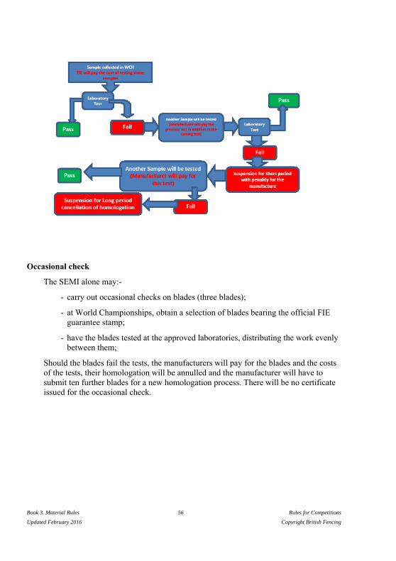
Book 3. Material Rules 56 Rules for Competitions
Updated February 2016 Copyright British Fencing
Occasional check
The SEMI alone may:-
- carry out occasional checks on blades (three blades);
- at World Championships, obtain a selection of blades bearing the official FIE
guarantee stamp;
- have the blades tested at the approved laboratories, distributing the work evenly
between them;
Should the blades fail the tests, the manufacturers will pay for the blades and the costs
of the tests, their homologation will be annulled and the manufacturer will have to
submit ten further blades for a new homologation process. There will be no certificate
issued for the occasional check.
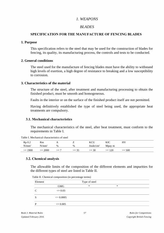
Book 3. Material Rules 57 Rules for Competitions
Updated February 2016 Copyright British Fencing
1. WEAPONS
BLADES
SPECIFICATION FOR THE MANUFACTURE OF FENCING BLADES
1. Purpose
This specification refers to the steel that may be used for the construction of blades for
fencing, its quality, its manufacturing process, the controls and tests to be conducted.
2. General conditions
The steel used for the manufacture of fencing blades must have the ability to withstand
high levels of exertion, a high degree of resistance to breaking and a low susceptibility
to corrosion.
3. Characteristics of the material
The structure of the steel, after treatment and manufacturing processing to obtain the
finished product, must be smooth and homogeneous.
Faults in the interior or on the surface of the finished product itself are not permitted.
Having definitively established the type of steel being used, the appropriate heat
treatments are compulsory.
3.1. Mechanical characteristics
The mechanical characteristics of the steel, after heat treatment, must conform to the
requirements in Table I.
Table I. Mechanical characteristics of steel
Rp 0.2 Rm A Z KCU KIC HV
N/mm2 N/mm2 % % Joule/cm2 Mpay m
>= 1900 >= 2000 >= 7 >= 35 >= 30 >= 120 >= 500
3.2. Chemical analysis
The allowable limits of the composition of the different elements and impurities for
the different types of steel are listed in Table II.
Table II. Chemical composition (in percentage terms)
Element Type of steel
GMG * *
C <= 0.03
S <= 0.0005
P <= 0.005

Book 3. Material Rules 58 Rules for Competitions
Updated February 2016 Copyright British Fencing
Si <= 0.10
Mn <= 0.10
Cr <= 0.50
Ni 18 - 20
Mo 4 - 5
Cu <= 0.30
Sn <= 0.005
Al 0.05 - 0
B <= 0.003
Co 8 - 13
Ti 0.5 - 2.0
Ca 0.005
Zr <= 0.02
* Types of steel still the subject of experiment must be included in this table, as they must conform to
the characteristics detailed in point 3.1 of the specification.
3.3. Manufacturing process
The products must be subjected to a manufacturing process corresponding to those
indicated for the different types of steel in Table III.
Table III. Manufacturing process
Type of steel Process
GMG 1. Forging at temperatures between 1150°C and 950°C
2. Air-cooling with the blades spaced apart
3. Mechanical machining (removal of extra thickness by reworking)
4. Homogenisation at 950°C ± 10°C for 1 hour
5. Immersion heat treatment at 820°C ± 10°C for 1 hour
6. Air-cooling with the blades spaced apart
7. Ageing at 480°C for 9 hours
8. Air-cooling with the blades spaced apart
9. Cold finishing
*
*
* Types of steel still the subject of experiment must be included in this table, as they must conform to
the characteristics detailed in point 3.1 of the specification.

Book 3. Material Rules 59 Rules for Competitions
Updated February 2016 Copyright British Fencing
4. Tests and examinations (material)
The tests and examinations to which the steel must be subjected are as follows:
— Chemical analysis
— Traction test
— Ductility tests
— Fracture resistance tests
4.1. Chemical analysis
The sample must have a minimum mass of 50 g. The chemical composition in
percentage terms must conform to that laid down in Table II for the corresponding
type of steel.
4.2. Traction test
The test must be conducted on a test sample of circular section whose dimensions are
indicated at the end of this annexe (Figure A.8), taken from materials that have been
subjected to the same heat treatment as specified for materials for the manufacture of
the blades.
The tensile strength values must conform to those laid down in Table I.
4.3. Tensile test
The test must be conducted on a test sample with a groove in the form of a V, whose
dimensions are indicated at the end of this annexe (Figure A.8), taken in the
longitudinal direction from materials that have been subjected to the same heat
treatment as specified for materials for the manufacture of the blades.
The value must conform to that laid down in Table I.
4.4. Test of fracture toughness, KIC
The KIC value of the steel must be measured by traction on a CT sample which has
the dimensions indicated at the end of this annexe (Table VIII), made from materials
subjected to the same thermal treatment as required for the blades, notched
mechanically initiating a fatigue crack at the apex of the notch. The test must be
conducted according to the methods indicated by the standard ASTM E 399. The
value must conform to that laid down in Table I.
In cases where it is not possible to obtain a CT sample, the factor of increasing levels
of dynamic loading (KId) may be determined instead of the KIC value.
The test must be conducted on ductility samples with a groove in the form of a
‘Charpy V’, with dimensions as indicated at the end of this annexe (Table VIII).
The results must conform to the reference standards.

Book 3. Material Rules 60 Rules for Competitions
Updated February 2016 Copyright British Fencing
5. Characteristics of the finished product
5.1. Shape
The blades, classified according to the type of weapon, must have the shapes
indicated in Annexe A and satisfy the conditions established by the FIE Rules.
5.2. Surface defects
The blades must be free of surface faults which could compromise their use (folds
in lamination, cracks, splinters, decarbonisation).
5.3. Surface roughness
At the conclusion of their manufacturing process the blades must be subjected to
finishing to ensure a surface roughness of <= 0.1 mm. The grinding marks must
only extend in the longitudinal direction of the blade.
6. Tests and examinations (finished product)
The tests and examinations to which the steel must be subjected are as follows:
— Chemical analysis
— Traction test
— Ductility test
— Test of fracture toughness, KId
— Hardness test
— Microscopic examination of the structure
— Corrosion test
— Non-destructive control
— Fatigue resistance test
6.1. Chemical analysis
The sample must have a minimum mass of 50 g. The chemical composition in
percentage terms must conform to that laid down in Table II for the corresponding
type of steel.
6.2. Traction test
The test must be conducted on a sample of circular section, taken from the blade,
whose dimensions are indicated at the end of this annexe (Figure A.8).
The values of the tension characteristics must conform to those laid down in Table
I.
Book 3. Material Rules 61 Rules for Competitions
Updated February 2016 Copyright British Fencing
6.3. Tensile test
The test must be conducted on a sample taken from the blade, without notches,
whose dimensions are indicated at the end of this annexe (Figure A.8). The value
must conform to that laid down in Table I.
6.4. Test of strength at the fracture point, KId
The KId value must be established by testing on the traction test samples with a
groove in the form of a ‘Charpy V’, with dimensions as indicated at the end of this
annexe (Table VIII).
The results must conform to the reference standards.
6.5. Hardness test
The hardness of the material, determined on the exterior surface of the finished
product, must conform to that laid down in Table I.
6.6. Microscopic examination of the structure
The examination must be carried out at 500 magnifications on a sample taken from
the blade.
The structure submitted must be smooth and homogeneous, conforming to grain
dimensions of 7–8 microns in accordance with the standard of reference and
corresponding to that resulting from the heat treatment specified in Table III for the
corresponding type of steel.
6.7. Non-destructive control
Before being put on the market, all blades must be subjected to a non-destructive
control, using an electromagnetic apparatus employing Foucault currents, to
explore for surface and below-surface faults. This control is compulsory, and must
be carried out over the entire surface of the blade.
6.8. Alternate bending test (optional)
In order to examine the behaviour of blades and the effects induced on the material
when the blades are deformed in a plastic manner by the method of alternate
bending, new blades selected at random and supplied from actual production lots
must be subjected to test using the special equipment indicated in the annexe.
The test consists of making a section of the blade bend plastically, in one direction
with a radius of inflexion of 60 mm, in the opposite direction with a radius of
inflexion of 100 mm, in order to obtain an approximate straightening.

Book 3. Material Rules 62 Rules for Competitions
Updated February 2016 Copyright British Fencing
The section of blade involved in the test must be approximately 155 mm long, of
which 60 mm from the point must not sustain any deformation.
A cycle consists of one bending plus one straightening. The result of the test is
represented by the number of cycles completed before the blade breaks.
To check safety conditions during the normal use of blades, the samples tested
must be subjected to a series of alternate bendings at a frequency of not more than
1 Hz (1 Hz = 1 cycle per second), verifying that the blade does not break before:
— 400 cycles for foil;
— 150 cycles for épée,
when the cycles have been conducted in accordance with the method described
above.
6.9. Fatigue resistance test of Blades (by bending, etc)
In order to examine the behaviour of the blades during normal fencing activity, the
blades to be tested must undergo a test of their resistance to metal fatigue, with a
special apparatus, either mechanical or pneumatic homologated by the FIE SEMI
Commission.
The test consists of bending the blade without exceeding the limit of elasticity of
the material, i.e. to the point where a bend of approximately 220 mm is reached,
corresponding to a shortening of the blade by approximately 250 mm, and then
allowing it to straighten.
The test machine must be able to allow the bending and straightening of the blade
at a frequency of 1 Hz (1 Hertz = 1 cycle per second).
The test benches are designed to reproduce the stresses to which a blade is
subjected in normal fencing activity. The stresses do not go beyond the limits of
the elasticity of the blades; a permanent deforming of the blade should not take
place. The number of bends to which a blade is subjected before breaking defines
its resistance to metal fatigue.
The test benches can be used for bending either without impact (with the end of the
blade attached to a revolving support) or with impact (with the end of the blade
unattached).
The test should continue until the blade breaks. For the result to be acceptable, it
must be ascertained that the blade does not break before:
— 18,000 cycles for foil blades;
— 7,000 cycles for épée blades.

Book 3. Material Rules 63 Rules for Competitions
Updated February 2016 Copyright British Fencing
6.10. Evaluation (in percentage terms) of the surface of the progressive fracture
The surface of the fracture obtained at the moment of breaking in the test in points
6.8 and 6.9 above must be analysed in order to measure the extent of the surface
over which the rupture has developed progressively.
The measure must be expressed as a percentage of the surface of the entire section
subject to the test.
The acceptability of the mechanical characteristics of the blade is confirmed when
the measured percentage value is not lower than 15% for foil and 6% for épée.
7. Results of tests and examinations
For each of the tests and examinations detailed in point 6 the results must comply with
the following table.
Table IV. Results of tests and examinations
Point of reference Examination or test Results
4.1, 6.1 Chemical analysis Must conform to Table II
4.2, 6.2 Traction test Must conform to Table I
4.3, 6.3 Tensile test Must conform to Table I
4.4, 6.4 Test of fracture resistance Must conform to Table I
6.5 Hardness test Must conform to Table I
6.6 Microscopic examination of structure Must conform to point 6.6
6.7 Non-destructive test Must conform to point 6.7
8. Marking
The identification mark of the manufacturer and the date of manufacture (year and
month) must be applied on each blade by cold-stamping near the entry into the guard,
to a maximum depth of 0.5 mm.
Note: All the standards may be modified. It is therefore important that manufacturers
of blades are absolutely sure that they are in possession of the latest edition or of the
latest update page.

Book 3. Material Rules 64 Rules for Competitions
Updated February 2016 Copyright British Fencing
EQUIPMENT
2. STANDARDS FOR THE MANUFACTURE OF FENCING MASKS
2.1. MESH OF FENCING MASKS
STANDARDS FOR THE MATERIALS FOR THE MESH OF FENCING
MASKS
1. Purpose
These specifications concern the technical quality of the round cold-drawn wire of
carbon stainless steel intended for the manufacture of the mesh of fencing masks, the
processes of its production, and the controls and tests to carry out in its use.
2. General conditions of raw material
The steel intended for the manufacture of the mesh of fencing masks must possess
excellent qualities of strength and a high level of elasticity and plastic deformation, as
well as a very good resistance against corrosion.
3. Materials
3.1. Chemical composition
The composition of the machined wire to be used to manufacture the wire
complying with the present rules, depending on the type of steel chosen, must
include the following, in percentage terms.
Table V. Chemical composition
Element Type of steel
304 304 L 321
C 0.03–0.06 < 0.03 < 0.08
Mn < 2 < 2 < 2
Si < 1 < 1 < 1
P < 0.04 < 0.04 < 0.04
S < 0.03 < 0.03 < 0.03
Cr 18–20 18–20 17–19
Ni 8–10.5 9–12 9–12
Ti – – 5 x Cmin (< 0.8)
For information, some of the most widely used types of steel are shown above; they
satisfy more or less the following defined standards:
— EURONORM 88-71 (EEC)
— UNI 6901-71 (Italy)
— AFNOR NF A 35-572 (France)
— DIN 17440 (Germany)

Book 3. Material Rules 65 Rules for Competitions
Updated February 2016 Copyright British Fencing
— BSI PD 6290 (Great Britain)
— MNC 900 E (Sweden)
— JIS G 4306-1972 (Japan)
— GOST 5632-61 (Russia)
3.2. Processing the steel and manufacturing the wire
The method of processing of the steel is entrusted to the supplier. The hot processing
to obtain the machined wire must be such that it can ensure a high level of consistency
in the materials and an absence of discontinuity and of faults in the interior and on the
surface of these same materials.
The process of cold wire drawing, to reduce the section in order to obtain the desired
diameter, must provide for adequate intermediate tempering for the manufacture of the
tempered materials. In any case the last step of the wire drawing must be preceded by
a chemical solution treatment at 1050–1100°C (stainless steel tempering) for types
304 and 304 L or a stabilisation treatment at 850–900°C for type 321.
The last step of the cold wire drawing must involve a hardening process defined
commercially as approximately 1/4 hard (H4), with a corresponding reduction in
section of <= 15% and carried out in such a way as to ensure the materials possess the
minimum values of the mechanical characteristics indicated in point 3.4.2 of this
specification.
3.3. Dimensions of the wire and tolerance
Table VI. Dimensions and tolerance
Diameter (d) Tolerance * on d Section Weight per 1000 m
(mm) (mm) (mm2) (kg)
1.0 ± 0.02 0.725 6.28
1.1 ± 0.02 0.950 7.50
* The lack of roundness of the wire must not exceed half the tolerance.
Intermediate values of the diameter of the wire are allowed on condition that they
conform to the tolerances indicated.
3.4. Conditions of supply
3.4.1. State in which supplied
The wire must be supplied bare with a polished surface: the surface must not show
any faults such as scratches, pockmarks or other imperfections.
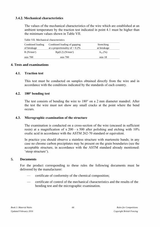
Book 3. Material Rules 66 Rules for Competitions
Updated February 2016 Copyright British Fencing
3.4.2. Mechanical characteristics
The values of the mechanical characteristics of the wire which are established at an
ambient temperature by the traction test indicated in point 4.1 must be higher than
the minimum values shown in Table VII.
Table VII. Mechanical characteristics
Combined loading Combined loading of gapping Stretching
of breakage at a proportionality of < 0.2% at breakage
R (N/mm2) Rp(0.2) (N/mm2) A50 (%)
min 700 min 700 min 18
4. Tests and examinations
4.1. Traction test
This test must be conducted on samples obtained directly from the wire and in
accordance with the conditions indicated by the standards of each country.
4.2. 180° bending test
The test consists of bending the wire to 180° on a 2 mm diameter mandrel. After
the test the wire must not show any small cracks at the point where the bend
occurs.
4.3. Micrographic examination of the structure
The examination is conducted on a cross-section of the wire (encased in sufficient
resin) at a magnification of x 200 – x 500 after polishing and etching with 10%
oxalic acid in accordance with the ASTM 262-70 standard or equivalent.
In practice you should observe a stainless structure with martensite bands; in any
case no chrome carbon precipitates may be present on the grain boundaries (see the
acceptable structure, in accordance with the ASTM standard already mentioned:
‘steep structure’).
5. Documents
For the product corresponding to these rules the following documents must be
delivered by the manufacturer:
— certificate of conformity of the chemical composition;
— certificate of control of the mechanical characteristics and the results of the
bending test and the micrographic examination.

Book 3. Material Rules 67 Rules for Competitions
Updated February 2016 Copyright British Fencing
2.1.2. TRANSPARENT MASKS
1. General
The FIE in its standard practices has established the possibility for fencers to use
either traditional masks made with metal mesh or transparent masks.
The transparent visor, when used, must be a minimum of 3.0 mm in thickness and must also have
a separate replaceable outer covering (a “sacrificial” layer) at least 1 mm in thickness. The visor
must be made of polycarbonate resin thermoplastic, and each mask and each replacement visor
must be accompanied, at the time of purchase, with a statement that guarantees the authenticity
and origin of the polycarbonate resin thermoplastic. The visor must correspond to the required
norms of materials and manufacture as indicated in 2.1.2. of the annex to chapter 3 (Materials) of
the rule book.
These transparent masks can be of two types:
— composite masks, made using traditional masks, of which a part of the front
mesh has been replaced by a visor of transparent plastic;
— masks made entirely of plastic, of which the front part must be transparent.
Currently only composite masks have been accepted by the FIE.
The wearing of the transparent mask is forbidden at all weapons and in all FIE
competitions.
2. Manufacturing norms for transparent masks
The norms are, at present, valid only for composite masks.
The starting point is a metal mesh mask; into the front part of the mesh, at eye level, a
window is made by cutting the mesh to a width that may reach as far as the lateral part
of the mesh and to a height that may not exceed 12 cm.
The window must be rimmed by a frame of stainless steel, made of two superimposed
sections, of which the first is to be soldered to the mesh and the second fixed to the
first by bolts.
The transparent visor made of polycarbonate (Lexan) will be placed between the two
parts of the frame.
Care must be taken that:
— The thickness of the steel gauge of each part of the frame must be between
0.8 mm and 1.0 mm.
— The edges of the frame which holds down the transparent visor must not be
sharp (cutting) and must adhere to the mesh, without any perceptible
projections.
Book 3. Material Rules 68 Rules for Competitions
Updated February 2016 Copyright British Fencing
— The part of the frame that is soldered must be fixed to the mesh before the
window is cut, to ensure that the shape of the mask is not altered when the
wires of the mesh are cut.
— The bolts fixing the two parts of the frame must not project beyond the nuts
into which they screw.
— The polycarbonate transparent visor (Lexan) must have a minimum
thickness of 3.0 mm, and a protective layer against damage to the outside
surface is recommended.
— The visor must not have any holes in it, must be shaped when hot, and
placed in its location in the frame, under no pressure, when cold and,
therefore, without being in any way ‘stressed’.
— There must be provision for an anti-condensation system on the inside of
the visor, or Lexan treated to this end must be used.
— Because of the damage caused to transparent visors during fencing
competitions, it is essential that fencers are able to change the visor of their
masks simply and easily.
— The padding of the mask must be reduced as much as possible, using any
system which will provide a circulation of air virtually equivalent to that of
the traditional mask.
— The total weight of the mask must not exceed 2 kg.
3. Safety standards
All transparent visor masks must provide a high level of safety for fencers. They must
therefore comply with very strict standards and in particular:
— The whole structure of the mask must be rigid and not be distorted as a
result of violent shocks.
— The metal mesh and the bib must have the same strength characteristics as
those of traditional masks.
— Because of ageing of the plastic material, the polycarbonate visor must only
be used for two years after its manufacture and, therefore, the date of
manufacture, using the format of month (two digits) and year (four digits),
e.g. 10-2010, must be indicated on it very clearly.
— To avoid degrading the polycarbonate, all contact with chemical agents that
can damage the material must be prevented; in particular, any presence of
PVC is unacceptable.
— The mask should be kept in a protective bag and it is desirable to avoid
putting the mask in the fencing bag (and hence in the aircraft hold) during
airplane journeys, but rather to keep it in hand luggage.

Book 3. Material Rules 69 Rules for Competitions
Updated February 2016 Copyright British Fencing
4. Homologation of transparent masks and test methods
Before being put on sale and used, all transparent visor masks must be approved and
homologated by the SEMI.
4.1. Homologation
To obtain FIE homologation, the manufacturer must send his masks to one of the
following three institutes: In Germany "Denkendorf" ; in France CRITT or IFTH.
The institute will conduct penetration resistance tests on the metal mesh and the
visor in accordance with the CEN norms (e.g. Norm EN 13567).
If the test results are positive, the constructor must send two examples of the mask
to be homologated, together with the Institute’s certificate, to the headquarters of
the SEMI in Lisbon, for the violent-shock tests.
If this result is also positive, the SEMI will issue the homologation certificate to the
manufacturer, and the mask may be put on sale and used at official FIE
competitions.
4.2. Violent-shock testing
Transparent visor masks must satisfy either the norms established by the CEN
Special Commission (cf. the paragraph on masks) or the additional norms estab-
lished by SEMI relating to resistance to violent shocks.
Therefore, in addition to the tests for resistance to penetration on several parts of
the mask as provided for by CEN norms, there is a need for a further test of the
resistance of the entire mask to violent shocks, which might occur as a result of
impact with the head or the guard of the opposing fencer.
This test will be carried out in the following manner.
4.2.1. Equipment for the test
The machine to be used must provide for a striker, of variable but known
weight, to fall from a height which is also variable, up to a maximum of 2 m.
Fixed to the striker there must be a rod, made of tempered steel, ending in a
head in the form of a sphere, with a diameter of 20 mm +/- 0.3 mm.
The rod must be 40–50 mm long and provided with a means of attaching it
(normally a thread) to the drop test machine (see Figure A.1)

Book 3. Material Rules 70 Rules for Competitions
Updated February 2016 Copyright British Fencing
.
Figure A.1. Test rod
An appropriate support for the mask must be provided on the base of the test
apparatus, to hold the mask firmly during the tests.
On the base of the apparatus, in effect, sliding structures must be in place
that can be fixed in an established position, so as to form a sort of rigid box
within which the mask is held (see Figure A.2).
Figure A.2. Method of affixing the mask
4.2.2. Drop equipment
The equipment to be used must allow a guided mass weighing between 3 kg
and 5 kg to drop from variable heights to achieve a maximum speed of
Book 3. Material Rules 71 Rules for Competitions
Updated February 2016 Copyright British Fencing
between 5 and 6 m per second at the moment of impact of the striker on the
sample to be tested.
A means must be arranged for stopping the drop weight, with the aim that
only the rod with the spherical end touches the mask, and not the weight.
The releasing mechanism of the striker must be controlled in such a way as
to ensure the same starting conditions, whatever the height of the drop.
The rod, as already specified in 4.2.1, must be fixed to the drop weight.
4.2.3. Sample to be tested
The sample to be tested must be the complete mask, but without the bib and
the trimmings.
The mask must be placed on the base of the test apparatus, with the front
part turned uppermost.
4.2.4. Successive test cycles
The tests must be conducted in the following order:
1. first test on the visor with the impact point of the sphere on the centre of
the mask and on the line crossing the centre of the visor;
2. second test on the same point.
4.2.5. Procedure
1. Fix the mask onto the base of the machine and the rod with the impact
sphere onto the drop weight of the drop test apparatus.
2. Place the mask in a such a way as to align the impact point on the mask’s
visor with the centre of the sphere.
3. Prepare the drop weight for a total weight of 5 kg +/- 0.03 kg, including
the rod and the impact sphere.
4. For the first test, raise the drop weight to a height that gives a distance
between the sphere and the point of impact on the mask visor of 1600
mm +/- 10 mm, corresponding to a drop energy of 80 joules.
5. Allow the drop weight to fall onto the mask.
6. For the second test, raise the same drop weight to a height of 1800 mm
+/- 10 mm, corresponding to a drop energy of 90 joules.

Book 3. Material Rules 72 Rules for Competitions
Updated February 2016 Copyright British Fencing
7. Allow the drop weight to fall onto the mask.
4.2.6. Test result
The result of the test is considered positive if the mask resists the two tests
without either deformation or damage to the visor itself, or to the frame
fixing the visor to the metal mesh.
Only a small impression on the polycarbonate visor, at the point of impact of
the test sphere, is acceptable.
2.1.3. MASKS THAT ARE COLOURED OR DECORATED
WITH DRAWINGS
Masks may feature coloured designs, on condition that they are approved by the FIE
Executive Committee at least 30 days before being used for the first time in an official
FIE competition.
2.2. SHAPE, DIMENSIONS AND METHODS OF PRODUCTION OF
THE ELEMENTS OF FENCING MASKS
TECHNICAL SPECIFICATION FOR THE
MANUFACTURE OF FENCING MASKS
1. Purpose
These technical specifications concern the shape, the dimensions, the methods of
production of the essential constituent elements of protective fencing masks, as well as
the technical quality of the materials intended for their manufacture.
2. General conditions
All the materials of which fencing masks are made and the corresponding
manufacturing processes must ensure an excellent mechanical resistance, a high
degree of visibility and comfort for the fencer and a sufficient resistance to wear and
tear and ageing.
3. Shape and dimensions of masks
The shape of masks is indicated schematically in Figure A.3 (viewed from the front,
from the side and from above). The dimensions of the frontal grille depend on the
dimensions of the mask. Those of the side grille must be as follows: the height
corresponding to 3/4 that of the front grille; the width being between 10 and 12 cm.
4. Essential constituent elements
The essential elements of the mask, as shown in Figure A.3, are:
(a) frontal grille protecting the face;

Book 3. Material Rules 73 Rules for Competitions
Updated February 2016 Copyright British Fencing
(b) lateral grille protecting the neck and the nape of the neck;
(c) strip for reinforcement and to connect the grilles;
(d) bibs.
The other parts, such as the interior protecting facings, padding, elastic bands and the
safety retaining devices, whose production is entrusted to the manufacturer, must
entirely conform to the conditions required for their use.
In particular, the rear fixing devices must ensure that the mask is located in the correct
position on the fencer’s head and that it remains in a perfect position, even after blows
or shocks.
Figure A.3. Design of masks

Book 3. Material Rules 74 Rules for Competitions
Updated February 2016 Copyright British Fencing
4.1. Front and side mesh
The mesh must be made of woven material with a square aperture, with an opening
of 1.9 mm, made entirely of round stainless steel wire CrNi 18-10 (the technical
quality of the wire for which is addressed in Table V on page 64).
In the curved zone of the grille the presence of mesh with an opening greater in
size than that specified is permissible, on condition that it does not exceed 2.1 mm.
The frontal grille must form an interior angle of <= 130°, corresponding to the fold
of the centre line.
4.2. Junction of the frontal and lateral mesh to the reinforcement band
The joining of the frontal mesh to the lateral one, by the reinforcement band, can
be accomplished by a mechanical joining (for example metal wire stitching, use of
rivets), or by solder.
In the case of solder, which in any case must be done using the usual techniques for
stainless steel, the operation must be completed by a careful mechanical polishing
of the soldered area, to eliminate slag and residues. The mesh must be entirely
covered in paint with a polymer base. Any heat treatments to harden and stabilise
the paint must be carried out at a temperature of <= 400°C.
4.3. Bibs
The bib must be formed from several layers of cloth firmly fixed to each other, of
which at least one on the inside must be made of Kevlar fibre or a similar
substance; in any case the cloth so formed must ensure a high degree of resistance
to penetration equal or greater than 1600 Newtons, to be tested by the methods
described in 3.1, below; it must also hinder the forming of stiff creases or the
rolling up of the bib itself.
The bib must be fixed to the exterior of the grille starting from the reinforcement
band onwards and extending as protection for the neck for a total height of the
order of 10–12 cm.
5. Test and certificates
For each model and production series of masks, the manufacturer will send three
examples to the SEMI Committee for testing that the mask conforms with the present
specifications, as well as photocopies of the certificates delivered by the manufacturer
of the mesh.
In the case of a positive result of this test, the manufacturer can place next to the
manufacturing mark the following information: ‘Conforms with standard … of the
FIE’ (‘conforme à la norme … de la FIE’).

Book 3. Material Rules 75 Rules for Competitions
Updated February 2016 Copyright British Fencing
3. CLOTHING
STANDARDS FOR THE MANUFACTURE OF CLOTHING
For the manufacture of fencing clothing it is obligatory to use material which is able to resist
perforation by a force of at least 800 Newtons. This resistance must be verified by the tests
defined in the following paragraphs.
3.1. RESISTANCE OF CLOTH AGAINST PERFORATION
STANDARDS FOR TESTING THE RESISTANCE
OF CLOTH AGAINST PERFORATION
1. Generalities
The method which is the subject of this standard is intended to determine the
resistance against perforation of cloth used to make up fencing uniforms.
The perforation load is defined as the maximum value of impact registered before the
sample of cloth is perforated by the test probe: the load is ex-
pressed in Newtons or else in kilogrammes of force to one decimal place.
2. Methods of conducting the test
2.1. The test takes place using a high speed dynamometer (as, for example, the
INSTROM 1273 apparatus) fitted with a moving test probe with a square
section of 3mm, a pyramidal head and an angle at the tip of 120º (see Figure
A.4, section A); this probe must be made of high speed or super high speed
steel, with a length of 70 mm, of which at least 50 mm juts out from the
holding device (see Figure A.4, section B).
2.1.1. The travel of the point must be perpendicular to the surface of the cloth
during the course of the test.
2.1.2. The speed of the probe during the test component of its travel must be
more than 6 m/s.

Book 3. Material Rules 76 Rules for Competitions
Updated February 2016 Copyright British Fencing
Figure A.4. High speed dynamometer for test of cloth resistance to perforation
2.2. The test must be conducted in a place where the temperature is 20–25°C and
with a relative humidity of 50–55%.
2.3. The samples for the test must be taken from a piece of cloth around 50 cm
high, free of faults and obtained at random at a distance of at least 2 m from
the ends.
The samples must be square in shape with sides of 14–15 cm and they must be
fixed on a device with a double vice (see Figure A.5) while leaving a section of
50 mm diameter free for the test.
In the case of fabrics made of several separated layers of cloth, a continuous
seam must be sewn along the sides of the square of material which constitutes
the sample.
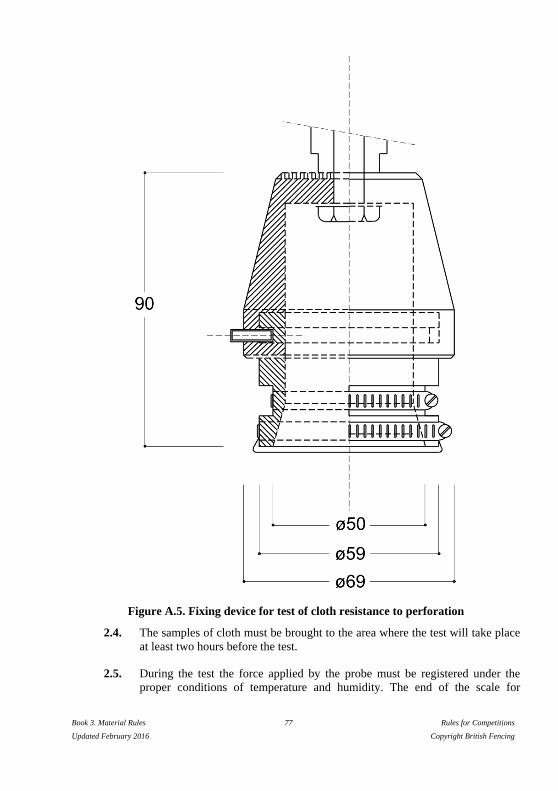
Book 3. Material Rules 77 Rules for Competitions
Updated February 2016 Copyright British Fencing
Figure A.5. Fixing device for test of cloth resistance to perforation
2.4. The samples of cloth must be brought to the area where the test will take place
at least two hours before the test.
2.5. During the test the force applied by the probe must be registered under the
proper conditions of temperature and humidity. The end of the scale for
Book 3. Material Rules 78 Rules for Competitions
Updated February 2016 Copyright British Fencing
measuring the forces must not be more than 5000 Newtons (with a tolerance of
± 5 Newtons).
2.6. For each cloth, at least three samples must be tested, taken at random from the
piece of cloth.
3. Results
The following data must be shown on the certificate confirming that the test has been
carried out:
(a) The name of the company applying, type and brand of cloth;
(b) The maximum force at the point of penetration for each sample and their
average, and the comparative graphic traces of the test;
(c) The type of dynamometer used, the type and speed of the probe in the test
component of its travel, and the conditions of the test (temperature and
relative humidity).
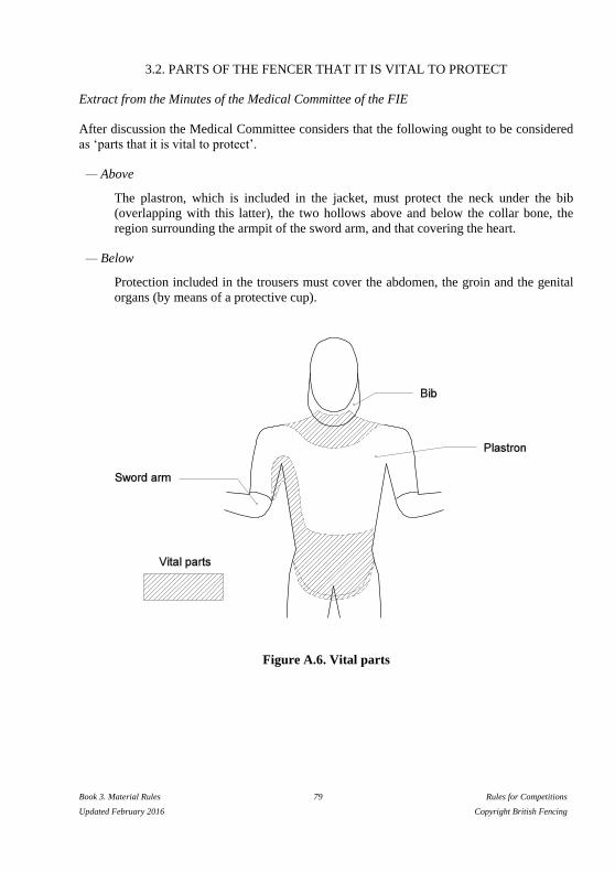
Book 3. Material Rules 79 Rules for Competitions
Updated February 2016 Copyright British Fencing
3.2. PARTS OF THE FENCER THAT IT IS VITAL TO PROTECT
Extract from the Minutes of the Medical Committee of the FIE
After discussion the Medical Committee considers that the following ought to be considered
as ‘parts that it is vital to protect’.
— Above
The plastron, which is included in the jacket, must protect the neck under the bib
(overlapping with this latter), the two hollows above and below the collar bone, the
region surrounding the armpit of the sword arm, and that covering the heart.
— Below
Protection included in the trousers must cover the abdomen, the groin and the genital
organs (by means of a protective cup).
Figure A.6. Vital parts

Book 3. Material Rules 80 Rules for Competitions
Updated February 2016 Copyright British Fencing
4. LABEL OF QUALITY
As far as the quality label is concerned, the Committee has established that it must be
indelible, must be circular in shape with a diameter of 25 mm for the mask and 50 mm
for the uniform, and must include the following data:
— the emblem of the manufacturer;
— the date (year and month) of manufacture;
— the FIE emblem.
On blades, the label must be 7 mm wide.
Figure A.7. FIE quality labels (not to scale)
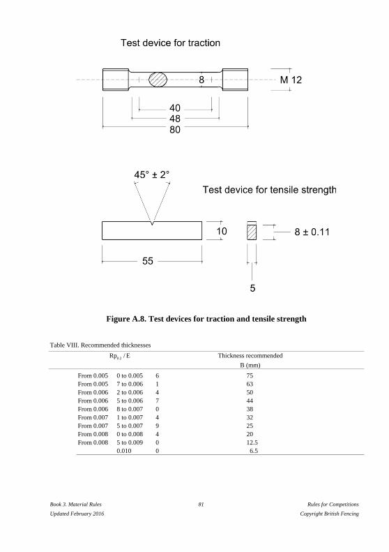
Book 3. Material Rules 81 Rules for Competitions
Updated February 2016 Copyright British Fencing
Figure A.8. Test devices for traction and tensile strength
Table VIII. Recommended thicknesses
Rp0.2
/ E Thickness recommended
B (mm)
From 0.005 0 to 0.005 6 75
From 0.005 7 to 0.006 1 63
From 0.006 2 to 0.006 4 50
From 0.006 5 to 0.006 7 44
From 0.006 8 to 0.007 0 38
From 0.007 1 to 0.007 4 32
From 0.007 5 to 0.007 9 25
From 0.008 0 to 0.008 4 20
From 0.008 5 to 0.009 0 12.5
0.010 0 6.5
Book 3. Material Rules 82 Rules for Competitions
Updated February 2016 Copyright British Fencing
ANNEXE B TO THE MATERIAL RULES
Characteristics of Scoring Apparatus
The installation of a clock and a system for showing the score are both
obligatory for the homologation of scoring apparatuses; they must be visible
to the spectators.
The clock must always be able to measure the time to a hundredth of second
throughout the match and it must transmit the time in hundredths of second to
the video refereeing system.
During the last 10 seconds of each period or bout of the match (both
individual and teams) it must display the time:
to a tenth of second when the judging apparatus is running
to a hundredth of second when the judging apparatus is stopped
The timer should be equipped with a small remote control, which can be fixed
onto two fingers of one hand. The remote control for the referee should be
provided with a single start/stop control and a LED light to show that the
device is working.
The connection between the remote control and the clock will operate with
encrypted radio frequencies: see the specific handbook concerning the radio
frequencies. [Application: season 2015/2016 for the World Championships
and the Olympic Games only: season 2016/2017 for the World Cup
competitions (Junior and Senior), the Grand Prix and the Zonal
Championships (Junior and Senior).]
A. FOIL
1. THE CENTRAL JUDGING APPARATUS (cf. m.51)
(a) Principles
1. The apparatus registers when a break occurs in the circuit of the foil, that is to say
that the electrical current which is circulating permanently in the foil circuit is
broken when a hit is made.
2. The apparatus will show a red signal on one side and a green signal on the other
when a hit is registered on target; white signals on either side will indicate hits off
the target.

Book 3. Material Rules 83 Rules for Competitions
Updated February 2016 Copyright British Fencing
3. The audible signals will consist either of a short ring, or of a continuous note which
will be automatically limited to two seconds. Either sort of sound will occur
whenever a visual signal appears. The sound signal must be identical for both sides
of the apparatus.
4. After registering a hit, whether on target or off target, the apparatus must no longer
be able to register a subsequent hit on the same side of the apparatus.
5. No priority must be indicated between a hit registered against one competitor and a
hit registered against his opponent.
6. After a period of time of 300 ms (± 25 ms tolerance) after the first hit signalled by
the apparatus (this period of time bears no relationship to ‘fencing time’ which is
the basis of judging according to the conventions governing foil fencing), the latter
must ignore all signals for subsequent hits.
(b) Sensitivity and regularity
1. Any hit must cause a signal whatever the resistance of the circuits external to the
apparatus. The duration of the break of contact which must always ensure that a
signal is registered is 14 ms (± 1 ms).
Depending on the increase in the resistance, the apparatus may register:
(1) a valid hit only;
(2) a valid hit and a non-valid hit simultaneously;
(3) a non-valid hit only.
The resistance must always be less than 500 ohms for (1) and (2).
2. The registering of a valid hit must be guaranteed when there is a break of contact
of 13–15 ms, when the exterior resistance is between 0 and 500 ohms.
3. The contact time is the same for valid and non-valid hits.
A break of contact of duration of 14 ms (± 1 ms) must always ensure that a signal
is registered, when the exterior resistance is between 0 and 200 ohms.
4. The apparatus must be capable of tolerating an increase in the resistance in the
closed circuit of the foils of up to 200 ohms, without causing a ‘non-valid’ signal to
register.
5. Even if the resistance of the foil earth circuit is increased up to 100 ohms, none of
the following irregular phenomena must occur:
— that hits are registered on the guard or on the piste;
Book 3. Material Rules 84 Rules for Competitions
Updated February 2016 Copyright British Fencing
— that it is possible to register a hit merely by contact of the blade or the
pointe d’arrêt (without depressing it) on the conductive jacket of either
competitor.
6. When the blades are in contact, irrespective of the resistance in ohms between
them, the apparatus must be capable of registering normally the hits exchanged,
valid and non-valid.
7. A specific programme of tests of apparatus under different conditions can be
supplied on request by the SEMI Committee of the FIE.
8. A specific programme of tests also includes the checking of the functioning of the
yellow lamps.
9. The Congress of the FIE has authorised this Committee to modify or add to the
above requirements whenever technical improvements allow the construction of
apparatus which can ensure the better operation of the electrical foil judging
apparatus.
2. ANTI-BLOCKING TYPE CENTRAL JUDGING APPARATUS
This apparatus must conform to the requirements of the rules set out in Articles m.44–
m.51 inclusive, as well as paragraphs (a) ‘Principles’ and (b) ‘Sensitivity and
regularity’ above, with the exception of point 6 of paragraph (b).
Even if a fault in the insulation in a fencer’s equipment causes a short between his
conductive jacket and his weapon, the apparatus should still be capable of registering
both valid and non-valid hits.
Depending on the resistance of the return circuit of the opponent’s foil, the apparatus
must register a valid hit up to 200 ohms and non-valid hits above this value.
The apparatus must be equipped with two yellow lamps regulated as follows. The
yellow lamp on the side of either fencer must automatically light up and remain alight
as soon as the resistance between the conductive jacket of that fencer and his weapon
is less than 450 ohms. When this resistance is in excess of 475 ohms, the yellow lamp
should never light up.
These yellow lamps serve only to indicate insulation faults.
If one or both of the yellow lamps remain lit up, the Referee must stop the bout and
call the technical experts on duty to eliminate the fault.
The yellow lamps need not indicate any contact between the fencer’s conductive
jacket and the conductive piste.

Book 3. Material Rules 85 Rules for Competitions
Updated February 2016 Copyright British Fencing
B. EPEE
(a) Principle
The apparatus registers when contact is established between the wires forming the
circuit in the épée, thus completing the circuit.
(b) Timing
The apparatus must register only the first hit which is made. If the interval of time
between two hits is less than 40 ms (1/25th of a second), the apparatus must register a
double hit (both signal lamps must light up simultaneously). When the interval is
greater than 50 ms (1/20 of a second) the apparatus must register only one hit (only
one signal lamp is lit). The tolerance allowed for timing the apparatus is that between
these two limits (1/25th and 1/20th of a second).
(c) Sensitivity
When the external resistance is normal, that is 10 ohms, the apparatus must register
hits when these are made with a duration of contact of 2–10 ms. With an exceptional
external resistance of 100 ohms the apparatus must still register a hit, but without any
specific duration of contact.
The apparatus must not register signals of less than 2 ms duration.
(d) Non-registration
The apparatus must not register hits which are made on the earthed material (on the
guard or on the conductive piste), even when there is a resistance of 100 ohms in the
earth circuit.
(e) Visual signals
1. Visual signals include at least two signal lamps on each side of the apparatus, so
designed that if one lamp does not function it does not prevent the other from
lighting up nor cause an excessive current through the latter.
2. The signal lamps should give a red signal on one side of the apparatus and a green
signal on the other.
3. The apparatus should have a pilot light to show that it is switched on. This light
should be dim and not coloured.
4. The apparatus may include lights which indicate short circuits to earth. These
should be orange in colour.
5. The light-bulbs which show when hits are registered are usually covered with
translucent shades. It must, however, be possible to remove these shades and use

Book 3. Material Rules 86 Rules for Competitions
Updated February 2016 Copyright British Fencing
naked lights, when the light conditions in the locality make it desirable to do so
(strong sunlight or, exceptionally, in the open air).
(f) Audible signals
The apparatus must have a loud sound signal. The apparatus may include a device
which allows the sound signal to be stopped before the apparatus is reset.
Book 3. Material Rules 87 Rules for Competitions
Updated February 2016 Copyright British Fencing
C. SABRE
(a) Principles
1. The apparatus works by contact between any uninsulated part of the sabre and the
conductive surface of the opposing fencer’s jacket, glove and mask.
2. For hits made on these valid conductive surfaces, the apparatus shows a red light
on one side and a green light on the other.
If the guard or blade of a fencer’s sabre is in contact with the conductive surface of
his own equipment (signalled by a yellow light), a valid hit made by that fencer
must still register.
3. The audible signal will consist of either one short ring or a continuous note lasting
1–2 seconds, simultaneous with the light signals. The sound will be the same for
both sides of the apparatus.
4. Hits made on non-conductive surfaces must not be signalled.
5. The apparatus must be equipped with two yellow lamps, one on each side, which
will indicate a contact between the guard or blade of a fencer’s sabre and the
conductive surface of his own equipment.
6. The apparatus must be equipped with two white lamps, identical to those on a foil
apparatus which, if permanently illuminated, accompanied by a sound signal,
indicate any abnormal electrical change in circuits B and C of the fencer at fault.
7. The apparatus must not signal a hit made by the blade whipping over to hit the
opponent while in contact with his blade or guard.
8. After a hit has been registered, a subsequent hit made by the other fencer will only
be registered if it occurs within a maximum of 120ms (± 10 ms).
8. After a hit has been registered, a subsequent hit made by the other fencer will only
be registered if it occurs within a maximum of 170 ms (± 10 ms).
Application: starting season 2016-2017.
9. When the two blades touch, all the other rules should be strictly applied.
10. The SEMI Committee of the FIE reserves the right to change the rules governing
the apparatus, either to simplify or to improve its performance.
Book 3. Material Rules 88 Rules for Competitions
Updated February 2016 Copyright British Fencing
(b) Sensitivity and regularity
1. The duration of contact during which a signal should be ensured should be 0.1–1
ms. These times may be varied in the light of experience and of laboratory tests
carried out by the SEMI Committee.
An apparatus will be rejected if a hit can be registered with a duration of contact of
less than 0.1 ms (time subject to modification).
2. The apparatus should allow an increase in the exterior resistance of the connections
up to 100 ohms without any drawbacks.
3. Should a fault in the insulation, down to 0 ohms, cause a leakage of current
between a fencer’s valid conductive surface and his weapon, the apparatus should
still be capable of registering all hits exchanged. The insulation fault will be
signalled by the illumination of the yellow lamp on the side of the fencer whose
equipment is at fault when the resistance is between 0 and 450 ohms.
The registering of a valid hit on the guard or blade of the fencer at fault will be
allowed provided that the electrical resistance between the guard or the blade and
the valid surface is less than 250 ohms.
4. The apparatus should still function when the blades are in contact, or if there is
contact between the blades and the guards, or between the two guards.
5. If the contact between the blade and the opponent’s target takes place ‘through the
blade’, the apparatus:
— will register the hit between 0 and 4 ms (+ 1 ms);
— will prevent the hit being registered between 4 and 15 ms (+ 5 ms), on
condition that the contact between the two blades is not interrupted more
than a maximum of 10 times in the interval.
6. Should there be a hit made by the whipping over of the blade which has not been
signalled, whatever method has been used to prevent the signalling, after 15 ms
(± 5 ms) from the contact of the blade with the valid target (the time for the
registering of the whip) and unless there has been another hit, the apparatus should
allow the normal registering of any subsequent hits.
7. A break in the control circuit (defined as more than 250 ohms) for 3 ms ± 2 ms will
be signalled by the illumination of the white lamp on the side of the fencer at fault.

Book 3. Material Rules 89 Rules for Competitions
Updated February 2016 Copyright British Fencing
ANNEXE C TO THE MATERIAL RULES
Score-board for Finals
Book 3. Material Rules 90 Rules for Competitions
Updated February 2016 Copyright British Fencing
INDEX TO ARTICLES
Numbers refer to articles of the Rules.
Accidental cause: m.25
Accumulators: see «Source of current»
Adjusting apparatus: Annexe B
Adjusting épée point: m.19
A Grade competitions (score-board):
m.60
Antiblocking: Annexe B
Apparatus: m.44ss
Apparatus (approval, homologation): see
«Approval of apparatus»
Apparatus (audible): see «Audible
signal»
Apparatus (characteristics): m.48,
m.51ss, Annexe B
Apparatus (checking): m.42, m.54, m.56
Apparatus (number): m.52
Approval of apparatus: m.46ss, m.54
Assembly (bodywire): m.29, m.31, m.35,
m.55
Assembly (mesh of mask): m.27,
Annexe A
Assembly (weapons): m.2, m.5, m.8,
m.16
Attachment (on handle): m.4s
Audible signal: m.45, m.51,
Annexe B
Back: see «Surface»
Band (non-conductive on conductive
jacket): m.28
Base of button: m.12, m.20
Bend of blade: m.8, m.16, m.23
Bib:m.25, m.27.2, m.30, m.32, An'xe A Black, clothing: m.25
Blade: m.1s, m.8, m.16, m.23
Blade (bend): see «Bend of blade»
Blade (button): see «Button (on
weapons)»
Blade (flexibility): see «Flexibility of
blade»
Blade (norms of manufacture): An.A
Blocking the scoring apparatus: Annexe
B
Bodywire: m.2, m.5, m.24, m.29, m.31,
m.35s, m.38, m.42, m.55
Breaking contact: m.5, m.11
Breast/chest protector: m.25
Breeches: m.25
Buckles on clothing: m.25
Button: m.2, m.12, m.13, m.16, m.19s,
m.23
Button (on weapons): m.2ss, m.8,
m.10ss, m.16ss, m.23
Cables (connection): m.44, m.51, m.55s
Cables (suspended): m.44
Characteristics of weapons: see
«Weapon»
Checking (equipment): m.25, m.36ss,
m.54; see also
«Gauge», «Weapon», «Weight»
Checking (of apparatus): see «Apparatus
(checking)»
Check marks: m.41ss
Chemical analysis: Annexe A
Chest protector: m.25
Chin: m.27.2
Clock: m.44, m.51
Clothing: m.25ss, m.37ss,
Annexe A
Collar: m.25, m.28, m.34
Coloured masks: Annexe A
Conductive wires (bodywire): m.29,
m.31, m.35
Conductive piste: m.29, m.44, m.51,
m.56, m.57, Annexe B
Conductive jacket: see «Jacket
(conductive)»
Conductive t-shirt: t.34
Conical sprung instrument: see «Mesh of
mask»
Contact, electrical: m.5, m.11, m.13,
m.19, m.29, m.32s, m.51, Annexe B
Control (fencers’ equipment): see
«Checking (equipment)»
Corrosion test: Annexe A

Book 3. Material Rules 91 Rules for Competitions
Updated February 2016 Copyright British Fencing
Crocodile clip: m.29, m.32, m.34
Cross-bar: m.4
Curve in blade: m.8, m.16, m.23
Cushion: see «Padding (guard)»
Cutting off the apparatus: Annexe B
Defective equipment: m.38,
Annexe A
Delegates — SEMI: see «SEMI
Committee»
Design of weapons: m.3ss; see also
«Epée», «Foil», «Sabre»
Device (safety): see «Safety device»
Dimensions (weapons): m.3, m.7ss,
m.15ss, m.21ss
Directoire Technique: m.12, m.20
Doing up (jacket and collar): m.25
Drawings (masks decorated with):
Annexe A
Ductility test: Annexe A
Duration of contact: see «Contact»
Eccentric mounting: m.9, m.17
Edges, sharpening: m.1
Electrical current: see «Source of
current»
Electric opposition: Annexe B
Epée: m.4s, m.14ss, m.30ss, Annexe A,
Annexe B
Equipment (of fencers): m.25ss, m.36ss,
Annexe A
Executive Committee: m.40
Extension (lamps): m.59
Field of play: see «Piste»
Filing blade: m.1
Fittings: m.44ss
Flange (collar): m.13, m.19
Flexibility of blade: m.42
Foil: m.1, m.4, m.6ss, m.26ss, m.42,
m.51, Annexe B
Fortuitous circumstances: m.25
Fatigue resistance test: Annexe A
Foucault currents: Annexe A
Fracture toughness, KIC, test: Annexe A
Gauge: m.4, m.9, m.17, m.24, m.42s
Gauntlet: m.25, m.33
Glove: m.4, m.25, m.26, m.33, Annexe
A
Grinding of blade: m.1
Grip: m.2s
Groove: m.8, m.10, m.12, m.18, m.20
Guard: m.1ss, m.5, m.9, m.17, m.24,
m.42, Annexe B
Handle: m.2ss, m.13, m.24
Hardness test: Annexe A
Insulating sheath: m.5, m.29, m.31
Insulation: m.5, m.13, m.19s, m.24,
m.27, m.28s, m.31, Annexe B
Jacket (conductive): m.13, m.28s,
m.32ss, m.36, m.38, m.42, m.51,
Annexe B; see also «Insulation»
Jacket (fencing): m.25, Annexe A
Jamming the apparatus: Annexe B
Label of safety/guarantee: m.37, Annexe
A
Lamé: m.28, m.34
Lamps: m.44, m.51, m.59,
Annexe B
Length of weapons: see
«Dimensions (weapons)»
Lighting stroke: m.11, m.19
Limits of piste: see «Piste»
Locking nut (blade): m.2, m.3
Logos, national: m.25
Mains electricity: m.51, m.60
Maraging steel: Annexe A
Marking of blades: Annexe A
Mask: m.25, m.27, m.30, m.32, m.37s,
m.42, Annexe A
Material: m.25ss, m.37ss, m.42,
m.44, m.57; see also «Bodywire»,
«Checking (equipment)», «Guard»,
«Mask», «Weapon»

Book 3. Material Rules 92 Rules for Competitions
Updated February 2016 Copyright British Fencing
Mesh of mask: m.25, m.27, m.32, m.42,
Annexe A
Microscopic examination:
Annexe A
Names: m.25
National clothing, logos, strip, uniform:
m.25
Neutralise: see «Insulation»
Newtons: m.25
Non-destructive control: Annexe A
On guard: m.25
Openings in equipment: m.25
Organising Committee: m.11, m.19,
m.40, m.42, m.52s
Orthopaedic (handle): m.4
Overglove: m.33.3
Padding (guard): m.2, m.5, m.24,
Annexe A
Piste: m.29, m.44, m.51, m.57, Annexe
B
Pistol grip: see «Orthopaedic (handle)»
Plastron (conductive): see «Jacket
(conductive)»
Plastron (protective): see «Under-
plastron»
Plugging in of bodywire: m.5, m.24,
m.29, m.31, m.35, m.55
Podium (piste): m.57, m.59
Pointe d’arrêt: m.10s, m.13, m.19, m.38,
m.42, Annexe A
Pommel: m.2, m.13, m.24
Pressure on pointe d’arrêt: m.11, m.19;
see also «Weight»
Protection (safety): m.25, Annexe A
Protective plastron: m.25,
Annexe A
Prototypes of apparatus: m.47, m.53
Registration of hits: m.39, m.45ss,
Annexe B
Regularity of apparatus: Annexe B
Re-setting switches: m.51
Resistance (clothing/bib/mask): m.25,
m.42
Resistance (electrical — ohms): m.5,
m.24, m.28s, m.31, m.32, m.42,
m.53, m.55, m.57, Annexe B
Sabre: m.1, m.4, m.21ss, m.32ss, Annexe
A, Annexe B
Safety: m.1, m.25, Annexe A
Safety device: m.55
Safety standards: m.8, m.16, m.25
Safety strap: m.25.7
Score-board (for finals): m.60, Annexe C
Section (of blades): m.8, m.16, m.23
SEMI (Committee): m.11s, m.19s,
m.28s, m.33, m.36, m.39s, m.46ss,
m.52ss, Annexe A, Annexe B
Sensitivity (apparatus): Annexe B
Sharpening edges of point: m.1
Sheath (insulating): m.5, m.29, m.31
Signals (visual): m.45, m.51, Annexe B
Signals (audible): m.45, m.51, Annexe B
Socket for bodywire: m.2
Socks: m.25
Solder: m.12, m.20, m.29, m.32, Annexe
A
Source of current: m.44, m.49, m.51,
m.58, Annexe B
Special device (handle): m.4
Spool: m.24, m.29, m.44, m.46, m.55s,
m.60
Springs (electric points): see «Weight»
Stretching device for piste: m.57
Strip: see «Piste»
Strip, national: m.25
Surface: m.3, m.5, m.12, m.20,
m.25
Surface (conductive jacket): m.28, m.34,
Annexe B
T-shirt: m.34
Tang of blade: m.2
Tearing out of spool: m.56
Test sample: Annexe A
Tests (equipment): Annexe A, Annexe B
Book 3. Material Rules 93 Rules for Competitions
Updated February 2016 Copyright British Fencing
Thread, cutting of: m.12, m.20
Throwing (weapon): m.4
Tolerance: m.11, m.19, Annexe A,
Annexe B
Traction test: Annexe A
Transparent masks: Annexe A
Travel (of the point): m.11, m.19,m.42
Treating a blade: m.1
Trim (on sabre mask): m.32,
Annexe A
Types of apparatus: m.46ss,
Annexe B
Under-plastron: m.25, Annexe A
Uniform, national: m.25
Unplugging of bodywire: m.55
Vest: see «Jacket (conductive)», «Jacket
(fencing)»
Visual signals: see «Lamps», «Signals
(visual)»
Voltage: see «Source of current»
Weapon: m.1ss, Annexe A; see also
«Dimensions», «Epée», «Foil»,
«Sabre», «Weight»
Weapon (checking): m.25, m.38,
m.42s
Weapon (throwing): m.4
Weight: m.6, m.8, m.11, m.14, m.16,
m.19, m.22s, m.28, m.42
Width of piste: see «Piste»
Wire (connecting to mask):, m.27.3,
m.32.5
Wireless fencing: m.44
Yellow lamps: Annexe B