rv 80 e 121 a b - nabtesco motion control, inc. · rv 80 e 121 a b e main bearing built ... called...
TRANSCRIPT

11
ORDERING INFORMATION1
■RV-E series
●Product identification for ordering purpose.
■RV-C series
●Product identification for ordering purpose.
RV 80 E 121 A B
Main bearing built-in typeE
Type of input gear orinput spline
●
●Speed ratio (reduction ratio = )1―R
Standard type A (Narrow type)AStandard type B (Big diameter type)BSpecial (none)Z
〈Ex. RV-80E〉
Notes1. Refer to the Rating Table for other type.2. Specify the shaft rotating speed ratio of your
application.
R shaft rotation 57,81,101,121,153
RV 100 C 36.75 A B
Bolt-clampingoutput shaftThrough-boltclamping outputshaft
B●
● T
Hollow shaft typeC
●Profile of center gear
●Speed ratio (reduction ratio = )1―R
Standard typeANoneZ
Notes1. Here, 36.75 applies to the RV-100C.2. See Ratings Table for speed ratios of other frame
numbers.3. Specify the shaft rotating speed ratio of your
application.
Frame number Rated output torque In-lb(Nm)6 514 (58)20 1,479 (167)40 3,649 (412)80 6,944 (784)110 9,547(1078)160 13,887(1568)320 27,774(3136)450 39,058(4410)
Frame number Rated output torque In-lb(Nm)10 867 (98)27 2,343 (265)50 4,340 (490)100 8,680 (980)200 17,359(1,961)320 27,775(3,136)500 43,398(4,900)
Type symbol●
Frame No.●
Model●
Type symbol●
Frame No. ●
Model●
Bolt-clampingoutput shaftBolt/pinclamping outputshaft
B●
● P

2
■RV series
●Product identification for ordering purpose.
RV 60 121 A T
Standard typeNo mark
Standard type A (Narrow type)AStandard type B (Big diameter type)BSpecial (none)Z
〈Ex. RV-60〉
Notes1. Refer to the rating table for other type.2. Specify the shaft rotating speed ratio of your
application.
R shaft rotation 57,81,101,121,153
Frame number Rated output torque In-lb(Nm)15 1,213 (137)30 2,949 (333)60 5,642 (637)160 13,887(1568)320 27,774(3136)450 39,058(4410)550 47,737(5390)
Type symbol●
Frame No. ●
Model●
Bolt-clampingoutput shaftThrough-boltclamping outputshaft
B●
● T
Type of input gear orinput spline
●
●Speed ratio (reduction ratio = )1―R

3
APPLICATION EXAMPLES2
Robot Swing AxisRV-C series●Allows space-saving design●Main bearing is not required onrobot side.
Robot armRV-C series●Greater internal resistance toadverse enovironments-allows safethroughput of cables.●Wider operating angle.
Indexing TableRV-C series

4
Robot armRV-E series
Robot Wrist AxisRV-E seriesAs shown in the figure(right), the input gearcan also be supported within the reductiongear mechanism.Please contact TS Corporation for moredetails.
Robot Swing AxisRV series

5
PositionerRV-E series
ATC MagazineRV-E series

RV-Cseries

54
RV
-C series
FEATURES AND BENEFITS1
Fig.1
●Cables and other lines can pass through the reduction gear●Allows space saving design
Hollow shaft structure
Benefits:●Increases reliabilty●Reduces overall cost
Attributed to:●Built-in angular ball bearing construction improves
ability to support external loads, increases momentrigidity and maximum allowable moment.
●Reduces the number of components required.●Simplifies installation and maintenance.
INTEGRATED ANGULAR BALL BEARINGS
Attributed to:●Low speed rotation of the RV gear reduces
vibration.●Reduced size of the motor coupling part (input
gear) lowers intertia.
Benefits:●Reduces vibration●Reduces inertia (GD2)
2 STAGE REDUCTION
Detail:●Crankshafts are supported on both sides of the
reduction gear as shown below.
Benefits:●Higher torsional stiffness●Less vibration●High shock load capability (5 times rated torque)
ALL MAIN ELEMENTS ARE SUPPORTED FROM BOTH SIDES
Attributed to:●Use of roller bearings throughout.
Benefits:●Excellent starting efficiency●Low wear and longer life●Low backlash (Less than 1 arc. min.)
ROLLING CONTACT ELEMENTS
Attributed to:●Synchromeshing of many precision ground gear
teeth and pins.
Benefits:●Very low backlash (Less than 1 arc. min.)●Higher shock load capability (5 times rated torque)
PIN & GEAR STRUCTURE
Clearance hole for rigidsupporting structure
Crankshaftthrough hole
RV gearRigid supporting structure
Crankshaft bearing supportsShaft + hold flange

55
CONSTRUCTION and OPERATION PRINCIPLE2
■Construction
■Principle of speed reduction
Fig.2
The RV-C is a 2-stage reduction gear.
…Spur gear reduction
●An input gear engages with and rotates a center gear which then engages and rotatesspur gears that are coupled to crankshafts. Several overall gear ratios can be providedby selecting various first stage ratios.
…Epicyclic gear reduction
●Crankshafts driven by the spur gears cause an eccentric motion of two epicyclic gearscalled RV gears that are offset 180 degrees from one another to provide a balanced load.●The eccentric motion of the RV gears causes engagement of the cycloidal shaped gear
teeth with cylindrically shaped pins located around the inside edge of the case.●In the course of one revolution of the crankshafts the teeth of the RV gear move the
distance of one pin in the opposite direction of the rotating cranks. The motion of theRV gear is such that the teeth remain in close contact with the pins and many teethshare the load simultaneously.●The output can be either the shaft or the case. If the case is fixed, the shaft is the
output. If the shaft is fixed, the case is the output.
2nd stage
1st stage
Fig.3
Crankshaft
Case Pin
RV gear
Main bearing
Hold flange
Input gear
Shaft
Spur gear
Center gear
Crankshaft rotating angle: 0 degree Rotating angle: 180 degrees Rotating angle: 360 degrees
CaseCrankshaft(Connected to spur gear)
Shaft
RV gear
Pin

56
RV
-C series
ROTARY DIRECTION and SPEED RATIO3
The rotary direction and speed ratio of the RV-C reduction gear are shown below.
Fig.4
■Speed RatioThe overall ratio can be determined from the following equation:
With the shaft as output; R=R1×
i=
(R1=1+ ・Z6)Z4――Z3
-1――R
Z2――Z1
Mechanism block drawing
Fig.5
qCase is fixed, shaft output wShaft fixed, case output
i=- 1―R i= 1―R
R : Overall speed ratioR1: Speed ratio of a discrete reduction gearZ1 : Number of teeth on input gearZ2 : Number of teeth on large center gearZ3 : Number of teeth on small center gearZ4 : Number of teeth on spur gearZ5 : Number of teeth on RV gearZ6 : Number of pinsi : Reduction ratio
Case
Shaft Crankshaft
RV gear
Pin
Output
Spur gear
Center gear
2nd reduction 1st reduction
Input gear

57
RATING TABLE4Table 1
Notes: 1. The overall speed ration is calculated with the formula in page 56.2. Set maximum input shaft speed to a value equal to or lower than the value of maximum allowable output speed multiplied by the overall speed ratio
for each type.3. The input capacity (KW) in the above table is determined by the efficiency of these reduction gears.4. The output torque (In-lb) is so determined that the service life may be maintained constant for any output revolutions. (N・T = Constant)5. The rated torque is a torque at an output speed of 15 r/min, which is used as a basis for service life calculations. (Refer to the rated service life, page
61.)
1,204 983 868 797 744 709 647 602
RV-10C 27 0.09 0.16 0.21 0.25 0.29 0.34 0.41 0.47
(136) (111) (98) (90) (84) (80) (73) (68)
36.57 3,259 2,648 2,347 2,152 2,010 1,904 1,745 1,630
RV-27C 0.26 0.42 0.55 0.68 0.79 0.90 1.10 1.29
(1,390/38)(368) (299) (265) (243) (227) (215) (197) (184)
32.54 6,031 4,907 4,340 3,985 3,720 3,525 3,242 3,020
RV-50C 0.48 0.77 1.03 1.26 1.47 1.67 2.04 2.38
(1,985/61)(681) (554) (490) (450) (420) (398) (366) (341)
12,063 9,804 8,679 7,962 7,448 7,050 6,465
RV-100C 36.75 0.95 1.55 2.05 2.51 2.94 3.33 4.08
(1362) (1107) (980) (899) (841) (796) (730)
34.86 24,125 19,617 17,368 15,968 14,932 14,144
RV-200C 1.90 3.09 4.11 5.04 5.88 6.69
(1,499/43)(2,724) (2,215) (1,961) (1,803) (1,686) (1,597)
35.61 38,624 31,335 27,774 25,516 23,824
RV-320C 3.04 4.94 6.57 8.05 9.41
(2,778/78)(4,361) (3,538) (3,136) (2,881) (2,690)
60,322 49,039 43,397 39,837
RV-500C 37.34 4.75 7.73 10.26 12.56
(6,811) (5,537) (4,900) (4,498)
Model
Output speed (r/min) 5 10 15 20 25 30 40 50
Output Input Output Input Output Input Output Input Output Input Output Input Output Input Output Inputtorque capacity torque capacity torque capacity torque capacity torque capacity torque capacity torque capacity torque capacity
Speedratio of adiscrete
reductiongear (R1)
In-lbkW
In-lbkW
In-lbkW
In-lbkW
In-lbkW
In-lbkW
In-lbkW
In-lbkW
(Nm) (Nm) (Nm) (Nm) (Nm) (Nm) (Nm) (Nm)
10―3

58
RV
-C series
6. The value is a value for a discrete reduction gear, and the for center and input gears is not included. Therefore, refer to the following
equation regarding the converted to motor shaft.
+ of input gear
7. If a higher speed than the above allowable maximum output speed is required, contact TS Corporation for further information.8. The output revolution is for forward-reverse changeover applications and not applicable for continuous rotation in a single direction. Contact TS
Corporation when using the reduction gear for continuous single-direction rotation.
GD2――4
of reduction gear unit + of center gear――――――――――――――――――――――――――――――――(Number of teeth on large center gear / Number of teeth on input gear)2
GD2――4
GD2――4
5763,726 6,076 12,151 2,170 4,340 416 10.1
0.54(421) (686) (1,372)
80(245) (490)
1(47)
1.34×10⁻⁵ 0.678×10⁻³(4.6)
(65)
1,5419,452 8,679 17,359 5,863 11,717 1,302 18.7
1.46(1,068) (980) (1,960)
60(662) (1,323)
1(147)
0.628×10⁻⁴ 0.563×10⁻³(8.5)
(174)
Bolt joint
17,346 15,623 31,246 10,84921,699
2,258 33.150 (2,450) 1 1.82×10⁻⁴ 0.363×10⁻²
(1,960) (1,764) (3,528) (1,225) Through-bolt joint (255) (15)17,359(1,960)
Bolt joint
24,895 21,699 43,397 21,69943,397
4,517 43.040 (4,900) 1 0.47×10⁻³ 0.953×10⁻²
(2,813) (2,450) (4,900) (2,450) Through-bolt joint (510) (19.5)30,378(3,430)
Bolt joint
86,730 78,115 156,230 43,39786,795
8,679 125.730 (9,800) 1 0.995×10⁻³ 1.94×10⁻²
(9,800) (8,820)(17,640) (4,900) Through-bolt joint (980) (57)65,096(7,350)
112,830 182,269 347,179 69,436 138,872 17,359 176.4
(12,740) (20,580)(39,200)25
(7,840)(15,680)1
(1,960)0.68×10⁻² 0.405×10⁻¹
(80)
216,990 303,781 694,358 108,493 216,987 30,378 352.7
(24,500) (34,300)(78,400)20
(12,250)(24,500)1
(3,430)0.98×10⁻²
(160)
60 Moment Allowable Momentary Allowable Allowable Momentary Lost Torsional Weightrigidity moment max. max. acceleration/ max. motion rigidity Inertia Inertia
Typical Value allowable output deceleration allowable (Stiffness) of reduction of centermoment speed torque torque Typical Value gear unit gear
In-lb/ In-lb (Shockload) (Continuous) In-lb (E-stop) MAX. In-lb/arc.min. (Nm) In-lb (Nm) In-lb arc.min. lb
(Nm/arc.min.) (Nm) r/min (Nm) arc.min. (Nm/arc.min.) kg-m2 kg-m2 (kg)
Output Inputtorque capacity
In-lbkW
(Nm)
GD2――4
GD2――4
GD2――4
I(= )GD2――4I(= )GD2
――4
( ) ( )

Maximum≦ output speed Input speed―――――――――Reduction gear ratio
Determine loadcharacteristic
Check the load torque applied to the speed reduction gear. An example is shown at right.
From the ratingtable
(page 57)
Temporary selectionof frame number
Service lifecalculation (Lh)
●Calculate average load torque (Tm)●Calculate average output speed (Nm)
Tm
Nm
Output speed
Output torque
Lh=Specified valueNO
Increase the framenumber or reducethe load.
Determinethe input speed
Determine the externalshock torque (Tem)due to emergency stop.
Determine the externalshock torque (Tout) whenmotor shaft speed is zero
Determinethe number ofallowable operationcycles (Cem)
NO
NO
NO
NOTout: Estimated value
C
TT
N tem
o
em
emem
=× ×
× ×
775 5
4060
103
L K NN
TT
ho
m
o
m= × ×
103
T t N T t N T t N Tt N t N t N
mn n n
n n= ⋅ ⋅ + ⋅ ⋅ + ⋅ ⋅ ⋅ ⋅ ⋅
⋅ + ⋅ + ⋅ ⋅ ⋅ ⋅
103
103
103
1031 1 1 2 2 2
1 1 2 2
N t N t N t Nt t t
mn n
n= ⋅ + ⋅ + ⋅ ⋅ ⋅ + ⋅
+ + ⋅ ⋅ ⋅ +1 1 2 2
1 2
(Refer to page 61)
Tout≦
Momentarymaximumallowabletorque
Tem≦
Momentarymaximumallowabletorque
T1and T3≦
Determinethe acceleration/deceleration torque(T1,T3)
Allowableacceleration/decelerationtorque
59
RV-C SELECTION5
5-1 Selection flow chart
N3N1
N2
T3
T2
T1
t1 t2 t3
0
Maximum acceleration torque
Outp
ut to
rque
Outp
ut s
peed
Time Maximumdecelerationtorque
Constant-speed torque
Constant-speedoperation time
Decelerationtime
Accelerationtime
Time
Fig.6
Table 2 Considerations for selection
Duty cycle diagram
For For For For impact duestarting constant stopping to emergency(Max) speed (Max) stop
Load torque In-lb T1 T2 T3 Tem
Speed r/min N1 N2 N3 Nem
Time sec t1 t2 t3 tem

END
Increase frame number ofreduction gear ordecrease that of load side.NO
NO
NO
NO
Determinemain bearing capacity
Determine output shafttorsion (θ)by external moment
W1r1+W2r3 θ=―――――――(r2>b) Mt (Refer to page 62.)
●Increase the frame number or reduce the load
Determineexternal moment (Mc)
Mc≦Allowable moment(table 1)
Frame selection
Mc=W1r2+W2r3(r2>b) (Refer to page 62.)
Check the external load applied tothe RV-C.RV-250 does not have built-inmain bearings.Please design and installexternal bearings.
θ≦
Allowabletorsion(required value)
θ≦
Allowabletorsion(required value)
≦Cem
Numberof operation
cycles
60
RV
-C series
Selection exampleSelection conditionsT1=5,310In-lb T2=1,328In-lbT3=2,655In-lb Tem=15,045In-lbt1=0.2sec. t2=0.5sec.t3=0.2sec. tem=0.05sec.N1=N3=10r/min N2=20r/minNem=20r/min
Determine load characteristic●Determine average load torque
=3,088In-lb●Determine average output speed
Provisional selection of RV-50C.●Calculation to determine whether reduction gear
service life meets required specification value.
●Determine output speedMaximum output speed 20r/min<50r/min
●Determine torque during starting and stoppingT1=5,310In-lb<10,849In-lb
T3=2,655In-lb<10,849In-lb
●Determine emergency stop and externalshock torqueTem=15,045In-lb<21,699In-lb
times
Determine main bearing capacity●External load conditionW1=550lbs r1=19.7in.W2=220lbs r3=7.9in.
Determine moment rigidity●Determine whether output shaft deflection
angle meets required specification value.
●Determine external moment
Mc=550×23.39+220×7.9=14,603In-lb<15,623In-lb
Since all required specification aresatisfied, select RV-50C.
7.37r2=19.7+―――=23.39in.
2
550×19.7+220×7.9θ=――――――――――――――=0.72(arc.min.)
17,346
Cem =× ×
× ×=
775 5 4,34015,045
40 2060
0 053,941
103
.
Momentary max. allowable torque for RV-50C
Allowable acc./dec. torque for RV-50C
Allowable acc./dec. torque for RV-50C
Maximum allowable output speed of RV-50C
L Hr= × × =6,000 1515.64,340 3,088
17,940103
0.2×10+0.5×20+0.2×10Nm=―――――――――――――=15.6r/min
0.2+0.5+0.2
Tm =× × + × × + × ×
× + × + ×
103
103
103
1030 2 10 5,310 0 5 20 1,328 0 2 10 2,655
0 2 10 0 5 20 0 2 10. . .
. . .
Allowable moment of RV-50C

61
■5-2-3 Rated service lifeThe service life of the RV-C reduction gear is based on the life of the rollerbearings of the crankshafts. The service life is set as shown in Table 3 for allmodels and ratios at rated torque and at rated output speed.
When in actual service installed in the equipment, calculate the service lifeusing the following formula because the load condition depends on the typesof reduction gear.
Lh=K× ×Lh : Service life to be obtained (Hr)Nm : Average output speed (r/min) (calculation on page 59)Tm : Average output torque (In-lb) (calculation on page 59)No : Rated output speed (r/min) (table 4)To : Rated output torque (In-lb) (table 4)
10―3To(―)TmNo――Nm
5-2 Strength and service life
■5-2-1 Allowable torque during acceleration or decelerationWhen the Machine starts (or stops), a larger torque than the steady-statetorque is applied to the reduction gear because of the inertial loads. Thevalues in the rating table (see page 57) show the allowable value of the peaktorque when the reduction gear starts or stops.The allowable acceleration/deceleration torque is 250% of the rated torque.
■5-2-2 Momentary maximum allowable torqueA large torque during an emergency stop or external shock may be appliedto the reduction gear. The maximum allowable torque is shown in the ratingstable(see page 57).Momentary maximum allowable torque is 500% of the rated torque.Note)When shock torque is applied, be sure to use at or below the limit cycle (refer to
selection flowchart on page 59).
Lh Service life (Hrs)L10 K 6,000
Type Rated torque In-lb(Nm) Rated output speed (N0)RV-10C 868 (98)RV-27C 2,347 (265)RV-50C 4,340 (490)RV-100C 8,679 (980) 15r/minRV-200C 17,368 (1,961)RV-320C 27,774 (3,136)RV-500C 43,397 (4,900)
(+)
(ー)
Acceleration torque
Deceleration torque
Momentary maximum torque
Constant speed torque
Load
torq
ue
Fig.7
Table 3
Table 4
Load torque graph

62
RV
-C series
5-3 Capacity of main bearing
Angular contact ball bearings are incorporated in the RV-C Series reductiongears so that external loads may be supported. However, the RV-250C isnot equipped with the built-in main bearings and users are requested todesign external bearings.
■5-3-1 Moment rigidityWhen an external load is applied to the output shaft, its deflection angle isproportional to the external moment (wherer2>b).The moment rigidity is expressed as an external moment value, which isrequired to deflect the output shaft 1 arc. min. (See Table 7.)
θ= W1r1+W2r3――――――――Mt
Table 5
Table 6
Moment rigidity (Mt) Size (in.)Model In-lb/arc.min.
Typical Value a bRV-10C 3,729 1.10 4.69RV-27C 9,459 1.50 5.92RV-50C 17,359 1.98 7.37RV-100C 24,914 2.31 8.17RV-200C 86,795 2.99 11.04RV-320C 112,833 4.5 14.19RV-500C 216,987 4.92 16.28
Allowable moment Allowable thrustModel In-lb(Nm) lbs(N)RV-10C 6,076 (686) 1,323 (5,880)RV-27C 8,679 (980) 1,984 (8,820)RV-50C 15,623 (1,764) 2,646 (11,760)RV-100C 21,699 (2,450) 3,086 (13,720)RV-200C 78,115 (8,820) 4,409 (19,600)RV-320C 182,269 (20,580) 6,614 (29,400)RV-500C 303,781 (34,300) 8,818 (39,200)
■5-3-2 Allowable momentTable 6 shows the external moment values(moments during starting andstopping, etc.) that can be supported by the RV-C Series.Refer to figure 9 indicating the range of allowable moment for simultaneousapplication of external moment and external thrust.
MC≦Allowable moment valueMC=W1r2+W2r3(r2>b)
Fig.8
θ :Deflected angle of output shaft (arc. min.)Mt :Moment rigidity (In-lb/arc.min.) (table 5)W1、W2 :Weight (lbs)r1、r3 :Arm length (in.)r1=r+ - a
r :The distance between the output shaft mounting surface andthe loading point (in.)
b―2
MC :External moment (In-lb)W1、W2 :Load (lb)r2、r3:Distance to load point(in.)r2=r+b-ar :Distance from output shaft mounting face to load point (in.)
External loading diagramOutput shaft mounting face

63
Fig.9
■5-3-3 Momentary maximum allowable momentA large torque and moment due to emergency stop or external impact maybe applied to the reduction gear.The rating table (page 57) shows the momentary maximum allowablemoment values.The momentary maximum allowable moment is twice the allowable moment.
Thrust force (lb)
Allowable moment (in-lb)
RV-100C
RV-50C
RV-27C
RV-10C
3,086
2,646
1,984
1,323
697
0
21,69915,5885,987
558386337
85915,2702,861
2,250
Thrust force (lb)
Allowable moment (in-lb)
RV-200C
RV-320C
RV-500C8,818
6,614
4,872
4,409
3,373
2,2051,830
0
303,781257,780182,269151,02378,11559,020
Allowable moment diagram

64
RV
-C series
PERFORMANCE CHARACTERISTICS6
6-1 Rigidity (Torsional rigidity and lost motion) and backlash
When a torque is applied to the output shaft while the input shaft (centergear) is fixed, torsion is generated according to the torque value and ahysteresis curve result is shown in Fig. 10.
The rigidity of the reduction gear is expressed by the torsional rigidity andthe lost motion in this curve. RV reduction gears are especially superior intheir stiffness characteristics.
●Torsional rigidity=
●Lost motionThe torsion angle at the mid point of the hysteresis curve width at ±3%of rated torque.●Backlash
The torsion angles when the torque indicated by the hysteresis curve iszero.
b―a
■6-1-1 Calculation of torsion (an example)Take an example of the RV-100C and find a torsion where a torque is appliedin one direction.1) If a torque of 88.5 In-lb is applied, the resulting torsion ST1, is found as
shown below.●Note that the torque is in the lost motion range.
ST1= × =0.17arc.min.
2) If a torque of 5,314 In-lb is applied, the resulting torsion ST2 is found asshown below.●Note that the torque is in the rated torque range.
ST2= + =1.62arc.min.
Note: The above torsion value is that of the reduction gear assembly.
5,314-260.4――――――――4,5171―2
1(arc.min.)――――――288.6―――260.4
Fig.10
ー100% +100%
a
b
Backlash
Tors
ion
angl
e
Lost motion
Rated torqueRated torque
±3% of rated torque
Hysteresis curve
Lost motionModel
Torsional rigidityLost motion Measured torque
BacklashIn-lb/arc.min.
arc.min. in-lbarc.min.
RV-10C 416 ± 26.0RV-27C 1,302 ± 70.3RV-50C 2,258 ± 130.2RV-100C 4,517 MAX1 ± 260.4 MAX1RV-200C 8,679 ± 520.8RV-320C 17,359 ± 833.4RV-500C 30,378 ± 1301.9
Table 7

65
The vibration is a torsional vibration in the circumferential direction whendriven by a servomotor with an inertia load applied.The vibration is one of the most important characteristics, especially whenprecise contouring control is required. For example, the industrial robotrequires exact and smooth contour control for its longer arm. An actualmeasured example of the vibration characteristics is shown in Fig. 11.
5000
0.1
0.2
1,000 1,500 2,000 2,500
Acceleration
Amplitude
Vibr
atio
nAc
cele
ratio
n (G
)
Half
ampl
itude
(mm
)
Servo motor input speed (r/min)
Fig.11
Test conditions1. Model: RV-100C2. Reduction ratio: 1/1613. Assembly accuracy:
Recommended accuracy (page 69)4. Load: Moment of inertia 107.8Nm・sec2
5. Measured radius: 550 mm
6-2 Vibration
6-3 Angular transmission accuracy
Angular transmission accuracy refers to a difference between the theoreticaloutput revolution angle and the actual revolution angle (θout) when anyrevolution angle (θin) is the input, and is expressed as an angulartransmission error (θer). The angular transmission error is found in thefollowing equation.
θer= -θout (where R = reduction ratio)
The measured example is shown below.
θin――R
Test conditions1. Model: RV-100C2. Assembly accuracy:
Recommended accuracy (see page 69)3. Load conditions: no-load4. Detector: USR324 + UC101
(manufactured by Nippon Kogaku K.K.) Resolution: 1 sec
Fig.12
Revolution of output shaft (degrees)
25 sec
Angu
lart
rans
mis
sion
erro
r(se
c)

66
RV
-C series
6-4 No-load running torque
6-5 Backdriving torque
The backdriving torque refers to a torque required for startingthe output shaft, with the RV-C reduction gear left under no-load. If the input shaft (input gear) is released while a torqueequal to or more than the backdriving torque is kept applied tothe output shaft, the input shaft (center gear) starts running atan augmented speed. Special care should be given to thebackdriving torque to start the RV-C reduction gear.
8,679
1,736
2,604
868
20 40 60 80 1000
RV-320C
RV-500C
RV-200C
RV-100C RV-50CRV-27C RV-10C
0
(N.m)
294
3,472 392
4,340 490
5,208 588
6,076 686
6,944 784
7,812 882
980
196
98
Output shaft speed (r/min)
In-lb(Nm)
No-lo
ad ru
nnin
g to
rque
(con
verte
d to
rque
on
the
outp
ut s
haft
side
)
Model Backdriving torque In-lb(Nm)RV-10C 89 (10)RV-27C 461 (52)RV-50C 841 (95)RV-100C 1,063 (120)RV-200C 1,328 (150)RV-320C 1,948 (220)RV-500C 2,657 (300)
Fig.13
Table 8
Test conditions1. Ambient temperature: 30℃2. Assembly accuracy: recommended accuracy
(see page 69)3. Lubricant: grease (Molywhite RE00)
Test conditionsAssembly accuracy: recommended accuracy
(see page 69)Lubricant: grease (Molywhite RE00)
The no-load running torque means a torque required on the input shaft(center gear) side in order to rotate the RV-C reduction gear under no load.Fig. 13 shows the no-load running torque on the output shaft side, which isconverted from the no-load running torque according to the followingequation.●No-load running torque converted to motor shaft (In-lb)
TM=TL× +frictional resistance of center gear
TL= (where R=speed ratio of RV reduction gear)
Note:The diagram below shows average values obtained after a RV-C reduction gear has beenrun in. The agitation resistance of center gear is not included in the values.
Converted torque on the output shaft side (In-lb)―――――――――――――――――
R
Z1―Z2
Z1:Number of teeth on input gearZ2:Number of teeth on large center gear

67
6-6 Low-temperature Characteristics (No-load running torque under low temperature)
Test conditions1. Assembly accuracy: recommended accuracy (page 69)2. Lubricant: grease (Molywhite RE00)3. Input speed: 15 r/min4. Loss at center gear is not included.
※Please inform TS Corporation if you have a plan to use the RV-500C incold temperature environment.
86.8
173.6
260.4
347.2
434.0
0ー10ー20 0 10 20
RV-10C
Case temperature (℃)
No-lo
ad ru
nnin
g to
rque
(con
verte
d to
out
put s
haft)
In-lb
(N.m)
39.2
49
29.4
19.6
9.8 173.6
347.2
520.8
694.4
867.9
0ー10ー20 0 10 20
RV-27C
Case temperature (℃)
No-lo
ad ru
nnin
g to
rque
(con
verte
d to
out
put s
haft)
In-lb
(N.m)
78.4
98
58.8
39.2
19.6
347.2
694.4
1,041.5
1,388.7
1,735.9
0ー10ー20 0 10 20
RV-50C
Case temperature (℃)
No-lo
ad ru
nnin
g to
rque
(con
verte
d to
out
put s
haft)
In-lb
(N.m)
156.8
196
117.6
78.4
39.2 867.9
1,735.9
2,603.8
3,471.8
4,339.7
0ー10ー20 0 10 20
RV-100C
Case temperature (℃)
No-lo
ad ru
nnin
g to
rque
(con
verte
d to
out
put s
haft)
In-lb
(N.m)
392
490
294
196
98
1,735.9
3,471.8
5,207.7
6,943.6
8,679.5
0ー10ー20 0 10 20
RV-200C
Case temperature (℃)
No-lo
ad ru
nnin
g to
rque
(con
verte
d to
out
put s
haft)
In-lb
(N.m)
784
980
588
392
196 1,735.9
3,471.8
5,207.7
6,943.6
8,679.5
0ー10ー20 0 10 20
RV-320C
Case temperature (℃)
No-lo
ad ru
nnin
g to
rque
(con
verte
d to
out
put s
haft)
In-lb
(N.m)
784
980
588
392
196
Fig.14
When the RV-C reduction gear is used under a low temperature, viscosity oflubricant increases and causes a larger no-load running torque. The no-load running torque under low temperature is shown below.

68
RV
-C series
6-7 Efficiency charts
Test conditions1. Case temperature: 30℃2. Assembly accuracy: recommended accuracy (page 69)3. Lubricant: grease (Molywhite RE00)4. Loss at center gear is not included.
RV-10C efficiency curve
Effic
ienc
y (%
)
0
20
40
60
80
10010r/min30r/min60r/min
217.0 (24.5)
434.0 (49)
651.0 (73.5)
867.9 (98)
1,084.9 (122.5)
In-lb (Nm)
Output torque
RV-27C efficiency curve
Effic
ienc
y (%
)
0
20
40
60
80
100
10r/min30r/min60r/min
2,169.9 (245)
1,735.9 (196)
1,301.9 (147)
867.9 (98)
434.0 (49)
In-lb (Nm)
Output torque
RV-50C efficiency curve
Effic
ienc
y (%
)
0
20
40
60
80
10010r/min30r/min50r/min
4,339.7 (490)
3,471.8 (392)
2,603.8 (294)
1,735.9 (196)
867.9 (98)
In-lb (Nm)
Output torque
RV-100C efficiency curve
Effic
ienc
y (%
)
0
20
40
60
80
10010r/min25r/min40r/min
6,943.6 (784)
5,207.7 (588)
3,471.8 (392)
1,735.9 (196)
In-lb (Nm)
Output torque
RV-200C efficiency curve
Effic
ienc
y (%
)
0
20
40
60
80
100 10r/min20r/min30r/min
17,358.9 (1,960)
13,019.2 (1,470)
8,679.5 (980)
4,339.7 (490)
In-lb (Nm)
Output torque
0
20
40
60
80
100 5r/min10r/min20r/min
52,076.843,397.434,717.917,358.9
RV-500C efficiency curve
Effic
ienc
y (%
)
In-lb (Nm)
Output torque
5r/min10r/min20r/min
0
20
40
60
80
100
34,717.927,774.320,830.713,887.26,943.6
RV-320C efficiency curve
Effic
ienc
y (%
)
In-lb (Nm)
Output torque
Fig.15

69
INSTALLATION AND ASSEMBLY7
7-1 Assembly accuracy
To get maximum performance from RV-C reduction gears, it is important topay attention to the assembly accuracy, installation, lubrication and sealing.Angular ball bearings are used as the main bearings with RV-C Seriesreduction gears. When designing the layout, make sure the bearing retainerwill not touch the motor mounting flange. Refer to the outline drawings onthe pages after page 78.Note: Two types of RV-C are available: bolt clamping output shaft type (refer to pages 77 to
83 for outline drawings, and through bolt clamping output shaft type (refer to pages 84to 89 for outline drawings excluding RV-500C). Please be sure to specify whenordering.
Design the assembly side of the RV-C reduction gear withintolerances shown in Table 9. Poor assembly accuracy causesvibration and particularly noise or backlash.
■7-1-1 Assembly accuracy
Table 9 (Unit:mm)
Tolerance of center- Concentricity Tolerance ofModel to-center distance X tolerance a parallelism b
RV-10CRV-27CRV-50CRV-100C ±0.03 MAX0.03 MAX0.03RV-200CRV-320CRV-500C
Fig.16
R indicates distance from center of reduction gear to center of motor.
Tole
ranc
e of
cen
ter-
to-c
ente
r dis
tanc
e±X

70
RV
-C series
7-2 Installation procedure
●The typical installation examples for RV-C reduction gearsare shown below. Be sure to seal the designated type ofgrease to the designated level. (See page 75)Slow speed tube and the output surface of the RV-Creduction gear need to be sealed.●Be sure that seals are used between mating parts on the
input side. Refer to the O-ring seal installation illustrated.●If the use of an O-ring seal is impossible because of the
design, use Gasket sealant. See table 10 at right.
Manufacturer Name
Loctite5699 Grey High PerformanceRTV Silicone Gasket MakerMoto Seal 2 Ultimate
PermatexGasket Maker White
Notes 1. Do not use for copper material or copper alloy material.2. If it is used under special conditions such as concentrated alkali, pressurized
steam, etc., please contact TS Corporation.
Table 10 Recommended Gasket sealant
Fig.18
Applicable O-ring sealRV-10C AS568-048RV-27C AS568-163RV-50C AS568-169RV-100C AS568-173RV-200C AS568-277RV-320C AS568-281RV-500C G460 (Metric)
Table 12 O-ring (II)
Fig.19
The O-ring (II) can be applied toboth bolt clamping and through-bolt clamping output shaft types.
■7-2-1 Assembly example of center tubeThe center tube is used to protect the cable which runsthrough the hollow section and to seal grease filled in thereduction gear. The assembly example of center tube isshown in Fig.18 for reference.
■7-2-2 Assembly example with the output shaft bolt clampingtype
If center tube, oil seal and O-ring (I) are used together, the seal on the mountingsurface of output shaft side is not required.
Refer to Table 12.
Table 11 Dimensions of O-ring (I) seal (for reference)
RV-10C RV-27C RV-50C RV-100C RV-200C RV-320C
Dim
ensi
ons
O-rin
gGr
oove
size
ID numberWire dia.I. D.I. D.: dWidth: B
CO 0625φ 2.4 ±0.07φ 29.7φ 30.2
3.2
0-0.08
(Unit:mm)
+0.250
CO 0634
φ 42.2φ 43.2 0
-0.08
CO 0643φ 3.5 ±0.1φ 59.6φ 60.3
4.7
0-0.10
+0.250
CO 0546Aφ 2.0 ±0.1φ 69.5φ 70.0
2.7
0-0.05
+0.250
G95 (Metric)φ 3.1 ±0.1φ 94.4φ 95.0
4.1
0-0.10
+0.250
G135 (Metric)
φ134.4φ135.0 0
-0.08
O-ring (I)
Oil seal
Center tube
Groove dimensionof O-ring (I)
▲ ― ― ―
▲ ― ― ―
▲ ― ― ―
▲ ― ― ―
RV-500C
G145 (Metric)
φ144.4φ145.0 0
-0.10▲ ― ― ―
▲ ― ― ―
O-ring (II)

71
Fig.20
Fig.21
Table 13Applicable O-ring (III) Applicable O-ring (IV)
RV-27C S75 (Metric) S120 (Metric)RV-50C S100 (Metric) S150 (Metric)RV-100C G115 (Metric) AS568-165RV-200C S150 (Metric) AS568-271
Table 14 O-ring(III)seal dimensions (for reference)
RV-10C RV-320C
Dim
ensi
ons
O-rin
gG
roov
esi
ze
ID numberWire dia.
I. D.O. D.: dDepth: HWidth: B
AS568-032φ 1.78 ±0.07φ 47.35 ±0.38φ 51.00
1.27 ±0.052.39
+0.050
(Unit:mm)
G210 (Metric)φ 5.7 ±0.13φ209.3φ220.0
5.5 ±0.057.5
+0.10
+0.250
+0.250
Table 15 O-ring(IV)seal dimensions (for reference)
RV-10C RV-320C
Dim
ensi
ons
O-rin
gG
roov
esi
ze
ID numberWire dia.
I. D.O. D.: dDepth: HWidth: B
S100 (Metric)φ 2.0 ±0.1φ 99.5 ±0.4φ103.0
1.52.7
+0.050
(Unit:mm)
0-0.1
G290 (Metric)φ 5.7 ±0.13φ289.3φ300.0
5.5 ±0.057.5
+0.10
+0.250
+0.250
■7-2-3 Assembly example of through-bolt clamping output shaft type(RV-27C, 50C, 100C and 200C)
The O-ring groove is provided at the end face of output shaft of the reduction gear.Use O-rings as shown below.
■7-2-4 Assembly example of through-bolt clamping output shaft type(RV-10C and 320C)
Provide the O-ring groove on the counterpart component. Dimensions of O-ringsare shown below for reference.
Refer to Table 13.
Refer to Table 13.
Refer to Table 12.
Refer to Table 15.
Refer to Table 14.
Refer to Table 12.
O-ring (IV)
O-ring (II)
O-ring (III)
O-ring (II)
O-ring (IV)
O-ring (III)
Groove dimensionsof O-ring (III) & (IV)
Notes: "G", "S" Part numbers are Japanese Industrial Standard (JIS B 2401) Metric O-Rings"CO" Part numbers are NOK's.

72
RV
-C series
7-3 Center gear and input gear
■7-3-1 Accuracy of center gear and input gearPoor installation accuracy of center gear and input gear may cause noise andbacklash, so design center gear and input gear to the following tolerances.
Tolerance of Tolerance of Tooth grade of Tooth grade of Tooth grade offitting X concentricity a small center gear large center gear input gear
h6 MAX0.03 JIS 5 class JIS 4 class JIS 5 class
Fig.25
Table 16 Accuracy of center gear and input gear (Unit:mm)
Table 17Backlash between input gear and large center gear
RV-10C 0.035~0.090RV-27C 0.040~0.110RV-50C 0.050~0.130RV-100C 0.060~0.140RV-200CRV-320C 0.075~0.180RV-500C
Table 18Module Number of teeth Addendum modification coefficient
RV-10C 1.0 48 -0.04RV-27C 1.0 57 +0.2RV-50C 1.25 61 0RV-100C 1.75 48 +0.3RV-200C 2.5 43 0RV-320C 2 78 0RV-500C 2 83 0
Module Number of teeth Addendum modification coefficientRV-10C 2 57 0RV-27C 1.25 78 0RV-50C 2 78 0RV-100C 1.75 112 0RV-200C 2 110 0RV-320C 2 125 0
(Unit:mm) Specifications of small center gear tooth
■7-3-2 Standard center gearThe standard center gears for RV-C reduction gear are available from TSCorporation.If the standard center gear is needed, please specify when ordering.Specifications of standard large center gears are shown below. Refer to theexternal dimension for installation.
Table 19 Specifications of standard large center gear
Small centergear
Large centergear
Tole
ranc
e of
fittin
g X
Input gear

73
7-4 Bolt tightening torque and allowable transmission torque
Use hexagonal socket bolts to assemble the RV-C reduction gear and tightento the torque as specified below. When the pin/bolt mounting output shaft typeis used, also use the taper pin. The serrated lock washer is recommended toprevent the bolt from loosening and protect the bolt seat face from flaws.
Bolt tightening torque and tightening forceHexagonal socket bolt Tightening torque Tightening force(R) Bolt specification
nominal size x pitch (mm) In-lb(Nm) NM5 ×0.8 80 ±4 (9.01±0.49) 9,310M6 ×1.0 138 ±7 (15.6 ±0.78) 13,180M8 ×1.25 329 ±16 (37.2 ±1.86) 23,960M10×1.5 651 ±30 (73.5 ±3.43) 38,080M12×1.75 1,137 ±56 (128.4 ±6.37) 55,100M14×2.0 1,814 ±90 (204.8 ±10.2) 75,860M16×2.0 2,821 ±141 (318.5 ±15.9) 103,410M18×2.5 3,906 ±196 (441 ±22.1) 126,720
Table 20
Notes 1. The valves listed are for steel or cast iron material.2. If softer material such as aluminum is used, limit the tightening torque. Also pay attention to the system torque requirements.
●Hexagonal socket boltJIS B 1176●Strength class
JIS B 1051 12.9●Thread
JIS B 0205 6g or class 2
Calculation of allowable transmission torque of bolts
T1=F× ×μ×n1D1――2T1 : bolt allowable transmission torque (Nm)F : bolt tightening force (N)D1 : bolt P.C.D. (m)μ : friction factorμ = 0.15: where lubricants remainedμ = 0.2: where left dried with no lubricant
n1 : number of bolts
Serrated lock washer external teeth for hexagonal socket bolt
Material: steelHardness: HRC40~48
O.D. and I.D. of washerNominal size d
Dt H
Basic size5 5.25 8.5 0.6 0.856 6.4 10 1.0 1.258 8.4 13 1.2 1.5510 10.6 16 1.5 1.912 12.6 18 1.8 2.214 14.6 21 2.0 2.516 16.9 24 2.3 2.818 18.9 27 2.6 3.15
Note:When using any equivalent washer, select it, with special care givento its outside diameter.
Fig.26
(Unit:mm)
Table 21

74
RV
-C series
To maximize the performance of the RV-C reduction gear, the use ofMolywhite RE00 manufactured by TS Corporation is recommended. Do notmix with other lubricants.
1) Grease level in RV-C reduction gearThe RV-C reduction gear when it is shipped from the plant is not greased.Therefore, ensure that the necessary amount of recommended grease ischarged when installing the RV-C reduction gear. Note: The quantity required for the RV-C reduction gear is shown below. The volume of
grease listed below does not include the volume required to fill the shaded areas infigure 28. These areas must also be charged with grease. When there exists a cavity,such as when a slow-speed tube is being used, exclude the volume of such cavity.However, too much filling may causes damage for an oil seal with increase of internalpressure. Please leave about 10% of the room inside.
Table 22 Working temperature range (ambient temperature)
Working temperature range-10℃~40℃
(ambient temperature)
Note: Please contact TS Corporation if grease or gear oil is to beused beyond the specified temperature range.
Vertical installation
TypeQuantitycc (g)
RV-10C 147 (128)RV-27C 266 (231)RV-50C 498 (433)RV-100C 756 (658)RV-200C 1,831(1,593)RV-320C 2,880(2,506)RV-500C 5,934(5,163)
TypeQuantitycc (g)
RV-10C 167 (145)RV-27C 305 (265)RV-50C 571 (497)RV-100C 857 (746)RV-200C 2,076(1,806)RV-320C 3,191(2,776)RV-500C 6,900(6,003)
Table 23 Horizontal installation
The profile of servomotor shaft and examples of input gear installation areshown below as a reference for designing. User must provide set screw,hexagonal socket bolt or hexagonal nut.
7-5 Installation of input gear
7-6 Lubrication
Straight shaft
(No female threaded on servomotor) (With female threaded on servomotor)
Fig.27
Taper shaft
(With male threaded on servomotor)Note: A radial load due to the counterforce of torque is applied
by the center gear on the RV-C reduction gear. Therefore,examine the strength of the motor shaft and the servicelife of bearings which support the motor shaft.
Setscrew
Hexagonal socket bolt
Hexagonal nut
75
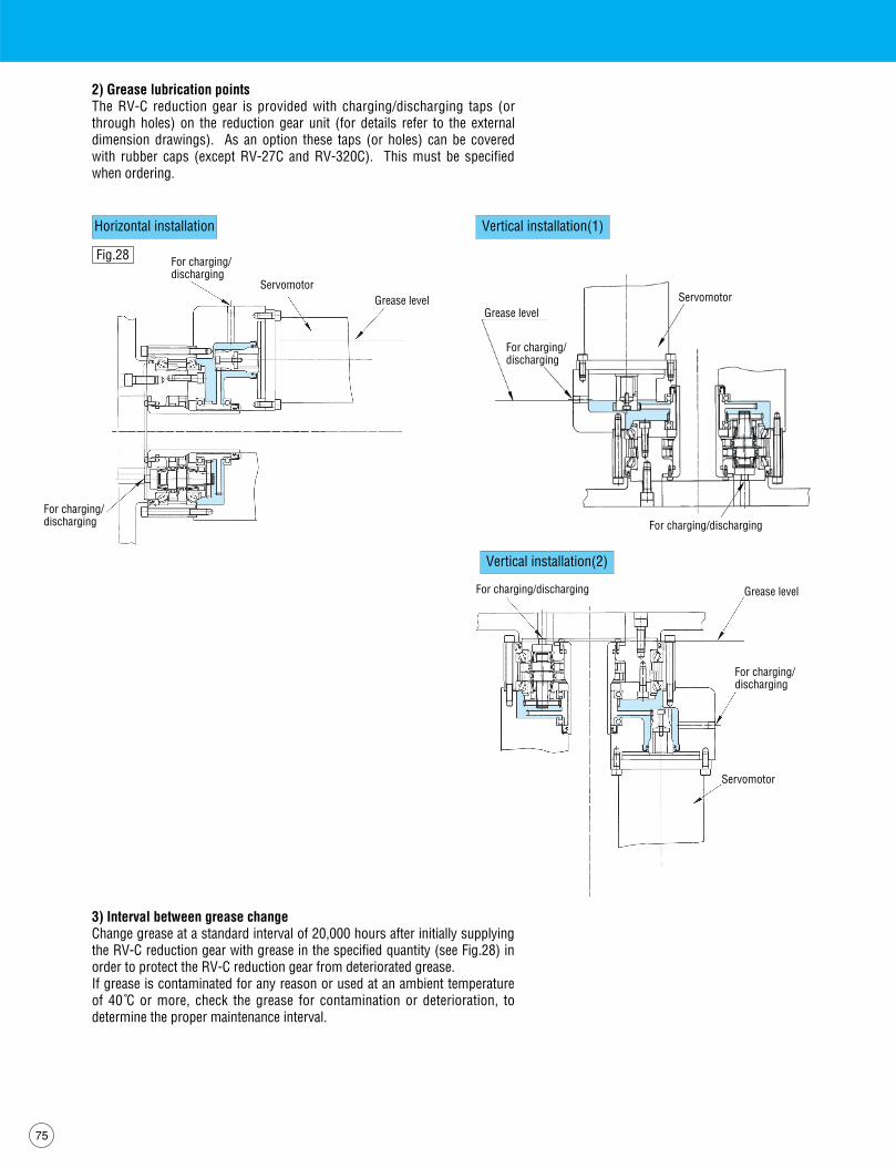
Horizontal installation Vertical installation(1)
Vertical installation(2)
Fig.28
2) Grease lubrication pointsThe RV-C reduction gear is provided with charging/discharging taps (orthrough holes) on the reduction gear unit (for details refer to the externaldimension drawings). As an option these taps (or holes) can be coveredwith rubber caps (except RV-27C and RV-320C). This must be specifiedwhen ordering.
3) Interval between grease changeChange grease at a standard interval of 20,000 hours after initially supplyingthe RV-C reduction gear with grease in the specified quantity (see Fig.28) inorder to protect the RV-C reduction gear from deteriorated grease.If grease is contaminated for any reason or used at an ambient temperatureof 40 C゚ or more, check the grease for contamination or deterioration, todetermine the proper maintenance interval.
For charging/discharging
Grease level
Grease levelServomotor
For charging/discharging
For charging/discharging
Servomotor
For charging/discharging
Grease level
For charging/discharging
Servomotor
For charging/discharging

76
RV
-C series
TS Corporation guaranties that the reduction gears of the model RV are freefrom defects of materials and workmanship.The term of guarantee shall be one year after delivery or 2,000 hours ofoperation after the installation on an actual machine,whichever earlier,oncondition that the product is operated under the rated operation conditionsspecified by us,in normal assembly and Iubrication condition.If any defect in materials or workmanship is detected during the aboveguaranteeterm,the product will be repaired or substituted at ourexpense,provided that the No.of man-hour required for demounting andremounting the product from the machine,transportation expense for re-delivery,warehousing and other incidental expenses shall be excluded fromour obligation.No expenses for damages of the machine due to shutdown of operationattributable to defect of the product are guaranteed.If the guarantee is accomplished with money,the upper limit of the amountshall not exceed the selling price of that claimed product.
7-7 Warranty

77
8-1
RV
-10C
Ext
erna
l dim
ensi
ons
of b
olt c
lam
ping
out
put s
haft
type
Type
cod
e RV
-10C
--
-BA
27
EXTERNAL DIMENTIONS8
Spee
d ra
tio
Allo
wab
le tr
ansm
issi
on to
rque
Num
ber o
f bolt
s & si
zeAll
owabl
e tran
smiss
ion to
rque
Case
sid
e8-
M6
1,05
8.4N
m
Shaf
t sid
e6-
M8
882N
mNo
tes1
. Use
com
mer
cial
goo
ds to
sup
ply
item
s su
ch a
s O-
rings
, mou
ntin
g bo
lts a
nd s
eal w
ashe
rs.
2. S
peci
ficat
ions
and
dim
ensi
ons
are
subj
ect t
o ch
ange
with
out n
otic
e.
Deta
il of
K
Sect
ion
H-H
(for l
ubric
atio
n)(1
pla
ce)
Sect
ion
G-G
(2 p
lace
s)

78
RV
-C series
8-2
RV
-27C
Ext
erna
l dim
ensi
ons
of b
olt c
lam
ping
out
put s
haft
type
Type
cod
e RV
-27C
--
-BA
36, 5
7Sp
eed
ratio
Allo
wab
le tr
ansm
issi
on to
rque
Num
ber o
f bolt
s & si
zeAll
owabl
e tran
smiss
ion to
rque
Case
sid
e12
-M6
1,99
9.2N
m
Shaf
t sid
e8-
M8
1,66
6Nm
Note
s1. U
se c
omm
erci
al g
oods
to s
uppl
y ite
ms
such
as
O-rin
gs, m
ount
ing
bolts
and
sea
l was
hers
.2.
Spe
cific
atio
ns a
nd d
imen
sion
s ar
e su
bjec
t to
chan
ge w
ithou
t not
ice.
Deta
il of
KSe
ctio
n F-
F (fo
r lub
ricat
ion)
(1 p
lace
)Se
ctio
n G-
G(2
pla
ces)

79
8-3
RV
-50C
Ext
erna
l dim
ensi
ons
of b
olt c
lam
ping
out
put s
haft
type
Type
cod
e RV
-50C
--
-BA
32, 5
4Sp
eed
ratio
Allo
wab
le tr
ansm
issi
on to
rque
Num
ber o
f bolt
s & si
zeAll
owabl
e tran
smiss
ion to
rque
Case
sid
e8-
M8
2,98
9Nm
Shaf
t sid
e9-
M10
3,41
0.4N
mNo
tes1
. Use
com
mer
cial
goo
ds to
sup
ply
item
s su
ch a
s O-
rings
, mou
ntin
g bo
lts a
nd s
eal w
ashe
rs.
2. S
peci
ficat
ions
and
dim
ensi
ons
are
subj
ect t
o ch
ange
with
out n
otic
e.
Deta
il of
K
Sect
ion
E-E
(for l
ubric
atio
n)(1
pla
ce)
Sect
ion
G-G
(2 p
lace
s)

80
RV
-C series
8-4
RV
-100
C E
xter
nal d
imen
sion
s of
bol
t cla
mpi
ng o
utpu
t sha
ft ty
peTy
pe c
ode
RV-1
00C-
--B
A36
, 75
Spee
d ra
tio
Allo
wab
le tr
ansm
issi
on to
rque
Num
ber o
f bolt
s & si
zeAll
owabl
e tran
smiss
ion to
rque
Case
sid
e14
-M10
9,31
0Nm
Shaf
t sid
e9-
M12
5,94
8.6N
mNo
tes1
. Use
com
mer
cial
goo
ds to
sup
ply
item
s su
ch a
s O-
rings
, mou
ntin
g bo
lts a
nd s
eal w
ashe
rs.
2. S
peci
ficat
ions
and
dim
ensi
ons
are
subj
ect t
o ch
ange
with
out n
otic
e.
Deta
il of
C
Sect
ion
J-J
(for l
ubric
atio
n)(1
pla
ce)
Sect
ion
E-E
(2 p
lace
s)

81
8-5
RV
-200
C E
xter
nal d
imen
sion
s of
bol
t cla
mpi
ng o
utpu
t sha
ft ty
peTy
pe c
ode
RV-2
00C-
--B
A34
, 86
Spee
d ra
tio
Allo
wab
le tr
ansm
issi
on to
rque
Num
ber o
f bolt
s & si
zeAll
owabl
e tran
smiss
ion to
rque
Case
sid
e8-
M12
10,7
01.6
Nm
Shaf
t sid
e9-
M16
13,5
43Nm
Note
s1. U
se c
omm
erci
al g
oods
to s
uppl
y ite
ms
such
as
O-rin
gs, m
ount
ing
bolts
and
sea
l was
hers
.2.
Spe
cific
atio
ns a
nd d
imen
sion
s ar
e su
bjec
t to
chan
ge w
ithou
t not
ice.
Deta
il of
K
Sect
ion
J-J
(for l
ubric
atio
n)(1
pla
ce)
82
RV
-C series
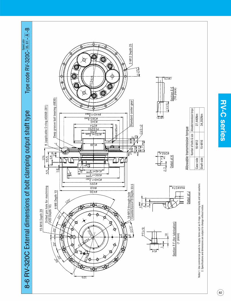
8-6
RV
-320
C E
xter
nal d
imen
sion
s of
bol
t cla
mpi
ng o
utpu
t sha
ft ty
peTy
pe c
ode
RV-3
20C-
--B
A35
, 61
Spee
d ra
tio
Allo
wab
le tr
ansm
issi
on to
rque
Num
ber o
f bolt
s & si
zeAll
owabl
e tran
smiss
ion to
rque
Case
sid
e16
-M12
27,4
40Nm
Shaf
t sid
e15
-M16
34,2
02Nm
Note
s1. U
se c
omm
erci
al g
oods
to s
uppl
y ite
ms
such
as
O-rin
gs, m
ount
ing
bolts
and
sea
l was
hers
.2.
Spe
cific
atio
ns a
nd d
imen
sion
s ar
e su
bjec
t to
chan
ge w
ithou
t not
ice.

83
8-7
RV
-500
C E
xter
nal d
imen
sion
s of
bol
t cla
mpi
ng o
utpu
t sha
ft ty
peTy
pe c
ode
RV-5
00C-
--B
Z37
. 34
Spee
d ra
tio
Allo
wab
le tr
ansm
issi
on to
rque
Num
ber o
f bolt
s & si
zeAll
owabl
e tran
smiss
ion to
rque
Case
sid
e24
-M12
49,0
88.2
Nm
Shaf
t sid
e18
-M16
44,6
68.4
NmNo
tes1
. Use
com
mer
cial
goo
ds to
sup
ply
item
s su
ch a
s O-
rings
, mou
ntin
g bo
lts a
nd s
eal w
ashe
rs.
2. S
peci
ficat
ions
and
dim
ensi
ons
are
subj
ect t
o ch
ange
with
out n
otic
e.

84
RV
-C series
8-8
RV
-10C
Ext
erna
l dim
ensi
ons
of th
roug
h-bo
lt cl
ampi
ng o
utpu
t sha
ft ty
peTy
pe c
ode
RV-1
0C-
--T
A27
Spee
d ra
tio
Allo
wab
le tr
ansm
issi
on to
rque
Num
ber o
f bolt
s & si
zeAll
owabl
e tran
smiss
ion to
rque
Case
sid
e8-
M6
1,05
8.4N
m
Shaf
t sid
e4-
M10
862.
4Nm
Note
s1. U
se c
omm
erci
al g
oods
to s
uppl
y ite
ms
such
as
O-rin
gs, m
ount
ing
bolts
and
sea
l was
hers
.2.
Spe
cific
atio
ns a
nd d
imen
sion
s ar
e su
bjec
t to
chan
ge w
ithou
t not
ice.
Sect
ion
H-H
(for l
ubric
atio
n)(1
pla
ce)
Sect
ion
G-G
(2 p
lace
)Se
ctio
n F-
F(4
pla
ce)
Deta
il of
K

85
8-9
RV
-27C
Ext
erna
l dim
ensi
ons
of th
roug
h-bo
lt cl
ampi
ng o
utpu
t sha
ft ty
peTy
pe c
ode
RV-2
7C-
--T
A36
, 57
Spee
d ra
tio
Allo
wab
le tr
ansm
issi
on to
rque
Num
ber o
f bolt
s & si
zeAll
owabl
e tran
smiss
ion to
rque
Case
sid
e12
-M6
1,99
9.2N
m
Shaf
t sid
e4-
M12
1,61
7Nm
Note
s1. U
se c
omm
erci
al g
oods
to s
uppl
y ite
ms
such
as
O-rin
gs, m
ount
ing
bolts
and
sea
l was
hers
.2.
Spe
cific
atio
ns a
nd d
imen
sion
s ar
e su
bjec
t to
chan
ge w
ithou
t not
ice.
Deta
il of
EDe
tail
of C

86
RV
-C series
8-10
RV
-50C
Ext
erna
l dim
ensi
ons
of th
roug
h-bo
lt cl
ampi
ng o
utpu
t sha
ft ty
peTy
pe c
ode
RV-5
0C-
--T
A32
, 54
Spee
d ra
tio
Allo
wab
le tr
ansm
issi
on to
rque
Num
ber o
f bolt
s & si
zeAll
owabl
e tran
smiss
ion to
rque
Case
sid
e8-
M8
2,98
9Nm
Shaf
t sid
e6-
M12
3,24
3.8N
mNo
tes1
. Use
com
mer
cial
goo
ds to
sup
ply
item
s su
ch a
s O-
rings
, mou
ntin
g bo
lts a
nd s
eal w
ashe
rs.
2. S
peci
ficat
ions
and
dim
ensi
ons
are
subj
ect t
o ch
ange
with
out n
otic
e.
Deta
il of
K
Deta
il of
HDe
tail
of J
Sect
ion
E-E
(for l
ubric
atio
n)(2
pla
ces)
Sect
ion
F-F
(6 p
lace
s)Se
ctio
n G-
G (2
pla
ces)

87
8-11
RV
-100
C E
xter
nal d
imen
sion
s of
thro
ugh-
bolt
clam
ping
out
put s
haft
type
Type
cod
e RV
-100
C--
-TA
36, 7
5Sp
eed
ratio
Allo
wab
le tr
ansm
issi
on to
rque
Num
ber o
f bolt
s & si
zeAll
owabl
e tran
smiss
ion to
rque
Case
sid
e14
-M10
9,31
0Nm
Shaf
t sid
e6-
M14
4,77
2.6N
mNo
tes1
. Use
com
mer
cial
goo
ds to
sup
ply
item
s su
ch a
s O-
rings
, mou
ntin
g bo
lts a
nd s
eal w
ashe
rs.
2. S
peci
ficat
ions
and
dim
ensi
ons
are
subj
ect t
o ch
ange
with
out n
otic
e.
Sect
ion
E-E
(2 p
lace
s)Se
ctio
n F-
F(6
pla
ces)
Sect
ion
J-J
(for l
ubric
atio
n)(1
pla
ces)
Deta
il of
DDe
tail
of G
Deta
il of
C

88
RV
-C series
8-12
RV
-200
C E
xter
nal d
imen
sion
s of
thro
ugh-
bolt
clam
ping
out
put s
haft
type
Type
cod
e RV
-200
C--
-TA
34, 8
6Sp
eed
ratio
Allo
wab
le tr
ansm
issi
on to
rque
Num
ber o
f bolt
s & si
zeAll
owabl
e tran
smiss
ion to
rque
Case
sid
e8-
M12
10,7
01.6
Nm
Shaf
t sid
e6-
M16
9,02
5.8N
mNo
tes1
. Use
com
mer
cial
goo
ds to
sup
ply
item
s su
ch a
s O-
rings
, mou
ntin
g bo
lts a
nd s
eal w
ashe
rs.
2. S
peci
ficat
ions
and
dim
ensi
ons
are
subj
ect t
o ch
ange
with
out n
otic
e.
Deta
il of
ESe
ctio
n F-
F(2
pla
ces)
Deta
il of
C
Deta
il of
K

89
8-13
RV
-320
C E
xter
nal d
imen
sion
s of
thro
ugh-
bolt
clam
ping
out
put s
haft
type
Type
cod
e RV
-320
C--
-TA
35, 6
1Sp
eed
ratio
Allo
wab
le tr
ansm
issi
on to
rque
Num
ber o
f bolt
s & si
zeAll
owabl
e tran
smiss
ion to
rque
Case
sid
e18
-M12
30,8
70Nm
Shaf
t sid
e9-
M18
21,5
60Nm
Note
s1. U
se c
omm
erci
al g
oods
to s
uppl
y ite
ms
such
as
O-rin
gs, m
ount
ing
bolts
and
sea
l was
hers
.2.
Spe
cific
atio
ns a
nd d
imen
sion
s ar
e su
bjec
t to
chan
ge w
ithou
t not
ice.