rv da indesign - braeco · 2015-04-07 · 1 rv-pvc • il raccoglitore di impurità fip elimina dal...
TRANSCRIPT

1
RV-PVC
• Il raccoglitore di impurità FIP elimina dal fluido di esercizio le impurità solide mediante una retina filtrante
• Gamma dimensionale da d 16 mm a d 110 mm, da R 3/8” a
R 4”• Resistenza a pressioni di eser-
cizio fino a 16 bar a 20° C (acqua)• Idoneità del PVC impiegato a
venire in contatto con acqua potabile ed altre sostanze ali-mentari secondo le leggi vigenti
• Possibilità di effettuare la ma-nutenzione con il corpo valvola installato
• FIP sediment strainer removes solid impurities in suspension in the fluid conveyed by means of a filter screen
• Size range from d 16 mm up to d 110 mm
• Pressure rating: maximum working pressure: up to 16 bar at 20° C (water)
• FIP PVC is suitable for con-veying foodstuffs and drinking water and meets the necessary standards and regulations
• Maintenance can be carried out while the valve body is installed in line
• Le filtre à tamis FIP élimine Ies impuretés solides de fluide, à l’aide d’un tamis
• Gamme dimensionnelle de d 16 mm jusqu’à d 110 mm
• Pression de service jusqu’à 16 bar à 20° C (eau)
• PVC à qualité alimentaire apte à l’utilisation avec l’eau potable et les aliments siuvant les régle-ments en vigueur
• Possibilité d’effectuer l’entretien sans devoir démonter le corps
• FIP-Schmutzfänger hal-ten mit ihrem Filternetz Verunreinigungen des Mediums zurück
• Abmessungsbereich von d 16 mm bis d 110 mm
• Druck: max. Betriebsdruck 16 bar bei 20° C (Wasser)
• FIP PVC entspricht den gel-tenden Vorschriften und ist für Trinkwasser oder andere für den Verzehr bestimmte Medien
zugelassen• Bei Wartungsarbeiten kann das
Gehäuse in der Rohrleitung verbleiben
Raccoglitore di impurità in PVC
PVC sediment strainer
Filtre à tamisen PVC
Schmutzfängeraus PVC-U
LEGENDA
d diametro nominale ester-no in mm
DN diametro nominale inter-no in mm
R dimensione nominale della filettatura in pollici
PN pressione nominale in bar (pressione max di esercizio a 20° C -
acqua - 50 anni)g peso in grammiK chiave del coperchioPVC cloruro di polivinile rigido
EPDM elastomero etilene propi-lene
FPM fluoroelastomero
d nominal outside diame-ter in mm
DN nominal internal diame-ter in mm
R nominal size of the thread in inches
PN nominal pressure in bar (max. working pressure at 20° C - water - 50 years)
g weight in gramsK bonnet wrench openingPVC uniplasticized polyvinyl
chlorideEPDM ethylene propylene rub-
ber FPM vinylidene fluoride rubber
d diamètre extérieur nomi-nal en mm
DN diamètre nominal inte-rieur en mm
R dimension nominale du filetage en pouces
PN pression nominale en bar (pression de service max à 20° C - eau - 50 années)
g poids en grammesK clef du couverclePVC polychlorure de vinyle
non plastifiéEPDM élastomère éthylène
propylène FPM fluorélastomère de vinyli-
dène
d Rohraußendurchmesser, mmDN Nennweite, mm
R Gewinde (DIN 2999, T1)
PN Nenndruck, bar (max Betriebsdruck bei
Wasser 2O° C -50 Jahre)
g Gewicht in GrammK SchlüsselweitePVC-U Polyvinylchlorid, hart ohne WeichmacherEPDM Äthylen-Propylen-
Kautschuk FPM Fluor-Kautschuk
Fig. A Fig. B Fig. C

2
RV-PVC
Dati Tecnici
2
4
5
Technical Data
Données Techniques
Technische Daten
Dimensioni della retina Filter screen sizes Dimensions du tamis Filternetz-Abmessungen
Coefficiente di flusso Kv100Per coefficiente di flusso Kv100 si intende la portata Q in litri al minuto di acqua a 20° C che ge-nera una perdita di carico Δ p = 1 bar per una determinata apertura della valvola.I valori Kv100 indicati in tabella si intendono per valvola completa-mente aperta.
FIow coefficient Kv100Kv100 is the number of Iitres per minute of water at a temperature of 20° C that wiII flow through a valve with a one-bar pressure differential at a specified rate. The Kv100 vaIues shown in the table are calculated with the valve completely open.
Coefficient de débit Kv100Kv100 est le nombre de litres par minute d’eau, à une température de 20° C, qui s’écoule dans une vanne de régulation avec une pression différentielle de 1 bar, à une vitesse donnée. Les valeurs Kv100 indiquées sur la table sont évaluées Iorsque le robinet est entièrement ouvert.
Kv100 -WerteDer Kv100- Wert nennt den Durchsatz in l/min für Wasser bei 20° C und einem Δ p von 1 bar bei völlig geöffnetem VentiI.
Diagramma delle perdite di carico
Pressure loss chart Diagramme de perte de charge Druckverlust-Diagramm
Variazione della pressione in fun-zione della temperatura per acqua o fluidi non pericolosi nei confron-ti dei quali il PVC è classificato CHIMICAMENTE RESISTENTE. Vedere il prospetto “Guida alla resistenza chimica”. In altri casi è richiesta un’adeguata diminuzione della pressione nominale PN.50 anni secondo DIN 3441
Pressure/temperature rating for water and harmless fluids to whi-ch PVC is RESISTANT. See“A guide to chemical resistance”.In other cases a reduction of the rated PN is required.50 years according to DIN 3441
Variation de la pression en fonction de la température pour I’eau et les fluides non agressifs pour lequels le PVC est considéré CHIMIQUEMENT RESISTANT. Voir “Guide de résistance chimique”. Pour Ies autres cas une diminu-tion du PN est nécessaire.50 années selon DIN 3441
Druck/Temperatur Diagramm fürWasser und ungefährliche Medien wogegen die PVC-U beständig ist (siehe Beständigkeitsliste).In allen anderen FäIIen ist eine Reduzierung derDruckstufe erforderlich.50 Jahre nach DIN 3441
Superficie totale di filtraggio At (cm2)
Total filtering screen surface At (cm2)
Surface filtrante du tamis At (cm2) Filteroberfläche, total At (cm2)
6350
101
403253
322536
2520
23,5
504069
201516
161016
dDNAt
7565
197
9080
247
110100396
passo (mm)hole pitch (mm)
pas de perforation (mm)Maschenabstand (mm)
numero di fori per cm2holes per cm2
n. des perforations par cm2Lochzahl/cm2
serie ASTM equivalente in meshequivalent ASTM mesh size
dimensions des perforations selon ASTMäquivalente ASTM Maschengröße
Ø foro equivalente µmØ equivalent hole µm
Ø perforation équivalente µmØ Gleighwertige Bohrung µm
materiale della retinascreen material
materiauxFilternetz
2,5
35
18
900
PVC
0,7
240
35
500
Inox
1,0
190
50
300
PVC
1,5
100
35
500
PVC
2,0
60
30
600
PVC
6350
410
4032
188
3225
103
252070
5040
255
201540
161022
dDN
kV100
7565
650
9080
1050
110100
1700
bar
16
14
12
10
8
6
4
2
0
-20 0 20 40 °C60 10080
bar
1
0,1
0,01
0,001
DN 10
DN 15
DN 20
DN 25
DN 32
DN 40
100 l/min1000 10000101
DN 50
DN 65
DN 80
DN 10
0
1
1
2
3
4
5
3pe
rdita
di c
arico
- pr
essu
re lo
st -
perte
de
char
ge -
Druc
kver
lust
portata - flow rate- débit - Durchflußmenge
pres
sione
di e
serc
izio
- wor
king
pre
ssur
epr
essio
n de
ser
vice
- Bet
riebs
druc
k
temperatura di esercizio - working temperaturetempérature de service - Betriebstemperatur
3
RV-PVC
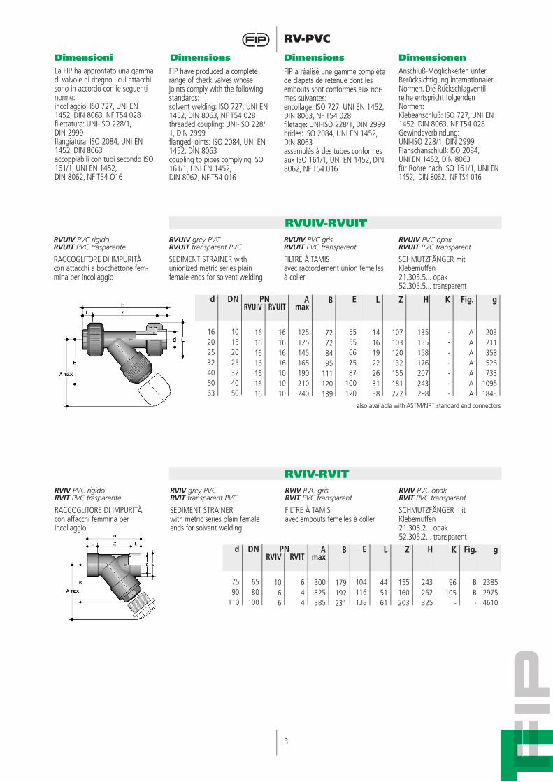
RVUIV PVC rigido RVUIT PVC trasparente
RACCOGLITORE DI IMPURITÀcon attacchi a bocchettone fem-mina per incollaggio
RVUIV grey PVCRVUIT transparent PVC
SEDIMENT STRAINER with unionized metric series plain female ends for solvent welding
RVUIV PVC grisRVUIT PVC transparent
FILTRE À TAMISavec raccordement union femelles à coller
RVUIV PVC opak RVUIT PVC transparent
SCHMUTZFÄNGER mit Klebemuffen21.305.5... opak52.305.5... transparent
Dimensioni Dimensions Dimensions Dimensionen
RVUIV-RVUIT
RVIV grey PVCRVIT transparent PVC
SEDIMENT STRAINERwith metric series plain female ends for solvent welding
RVIV PVC gris RVIT PVC transparent
FILTRE À TAMISavec embouts femelles à coller
RVIV PVC opak RVIT PVC transparent
SCHMUTZFÄNGER mit Klebemuffen21.305.2... opak52.305.2... transparent
RVIV-RVIT
La FIP ha approntato una gamma di valvole di ritegno i cui attacchi sono in accordo con le seguenti norme:incollaggio: IS0 727, UNI EN 1452, DIN 8063, NF T54 028filettatura: UNI-ISO 228/1,DIN 2999flangiatura: ISO 2084, UNI EN 1452, DIN 8063accoppiabili con tubi secondo ISO 161/1, UNI EN 1452,DIN 8062, NF T54 O16
FIP have produced a complete range of check valves whose joints comply with the following standards:solvent welding: ISO 727, UNI EN 1452, DIN 8063, NF T54 028 threaded coupling: UNI-ISO 228/1, DIN 2999flanged joints: ISO 2084, UNI EN 1452, DIN 8063coupling to pipes complying ISO161/1, UNI EN 1452,DIN 8062, NF T54 016
FIP a réalisé une gamme complète de clapets de retenue dont Ies embouts sont conformes aux nor-mes suivantes:encollage: ISO 727, UNI EN 1452, DIN 8063, NF T54 028filetage: UNI-ISO 228/1, DIN 2999 brides: ISO 2084, UNI EN 1452, DIN 8063assemblés à des tubes conformes aux ISO 161/1, UNI EN 1452, DIN 8062, NF T54 016
Anschluß-Möglichkeiten unterBerücksichtigung internationaler Normen. Die Rückschlagventil-reihe entspricht folgenden Normen:Klebeanschluß: ISO 727, UNI EN 1452, DIN 8063, NF T54 028Gewindeverbindung:UNI-ISO 228/1, DIN 2999FIanschanschluß: ISO 2084,UNI EN 1452, DIN 8063für Rohre nach ISO 161/1, UNI EN 1452, DIN 8062, NF TS4 016
d
16202532405063
DN
10152025324050
A max
125125145165190210240
RVUIT
16161616101010
RVUIV
16161616161616
B
72728495
111120139
L
14161922263138
E
5555667587
100120
Z
107103120132155181222
H
135135158176207243298
K
-------
Fig.
AAAAAAA
g
203211358526733
10951843
PN
d
7590
110
DN
6580
100
A max
300325385
RVIT
644
RVIV
1066
B
179192231
L
445161
E
104116138
Z
155160203
H
243262325
K
96105
-
Fig.
BB-
g
238529754610
PN
also available with ASTM/NPT standard end connectors
RVIV PVC rigido RVIT PVC trasparente
RACCOGLITORE DI IMPURITÀcon affacchi femmina per incollaggio
4
RV-PVC
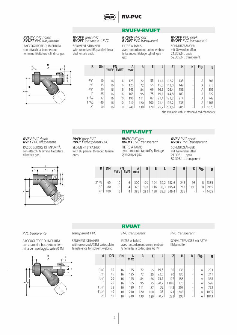
RVUFV PVC rigidoRVUFT PVC trasparente
RACCOGLITORE DI IMPURITÀcon attacchi a bocchettonefemmina filettatura cilindrica gas
RVUFV grey PVC RVUFT transparent PVC
SEDIMENT STRAINERwith unionized BS parallel threa-ded female ends
RVUFV PVC grisRVUFT PVC transparent
FILTRE À TAMISavec raccordement union, embou-ts taraudés, filetage cylindrique gaz
RVUFV PVC opak RVUFT PVC transparent
SCHMUTZFÄNGERmit Gewindemuffen21.305.6... opak52.305.6... transparent
RVUFV-RVUFT
R
3/8”1/2”3/4”
1”1”1/41”1/2
2”
DN
10152025324050
A max
125125145165190210240
RVUFT
16161616101010
RVUFV
16161616161616
B
72728495
111120139
L
11,415,016,319,121,421,425,7
E
5555667587
100120
Z
112,2112,0126,4144,8171,2192,2233,6
H
135142159183214235285
K
-------
Fig.
AAAAAAA
g
206210355522742
11061873
RVFV PVC rigido RVFT PVC trasparente
RACCOGLITORE Dl IMPURITÀcon attacchi femmina filettatura cilindrica gas
RVFV grey PVCRVUFT transparent PVC
SEDIMENT STRAINERwith BS parallel threaded female ends
RVFV PVC grisRVUFT PVC transparent FILTRE À TAMISavec embouts taraudés, filetage cylindrique gaz
RVFV PVC opak RVUFT PVC transparent
SCHMUTZFÄNGERmit Gewindemuffen21.305.1... opak52.305.1... transparent
RVFV-RVFT
PN
R
2”1/23”4”
DN
6580
100
A max
300325385
RVFT
644
RVFV
1066
B
179192231
L
30,233,339,3
E
104116138
Z
182,6195,4246,4
H
243262325
K
96105
-
Fig.
BB-
g
238529654405
PN
also available with JIS standard end connectors
d
3/8”1/2”3/4”
1”11/4”11/2”
2”
DN
10152025324050
B
72728495
111120139
A max
125125145165190210240
PN
16161616101010
E
5555667587
100120
Z
9690
107118,6
143173222
L
19,522,525,528,7
3235
38,2
H
135135158176207243298
K
-------
Fig.
AAAAAAA
g
203211358526733
10951843
PVC trasparente
RACCOGLITORE DI IMPURITÀcon attacchi a bocchettone fem-mina per incollaggio, serie ASTM
transparent PVC
SEDIMENT STRAINERwith unionized ASTM series plain female ends for solvent welding
PVC transparent
FILTRE À TAMISavec raccordement union, embou-ts femelles à coller, série ASTM
PVC transparent
SCHMUTZFÄNGER mit ASTM Klebemuffen
RVUAT

5
RV-PVC
d
3”4”
DN
80100
B
192231
A max
325385
PN
44
E
116138
Z
166,8210,6
L
47,657,2
H
262325
K
105-
Fig.
B-
g
29754610
PVC trasparente
RACCOGLITORE DI IMPURITÀcon attacchi femmina per incol-laggio, serie ASTM
transparent PVC
SEDIMENT STRAINERwith ASTM series plain female ends for solvent welding
PVC transparent
FILTRE ÉPURATEUR À TAMISavec embouts femelles à coller, série ASTM
PVC transparent
SCHMUTZFÄNGER mit ASTM Klebemuffen
RVAT
R
3/8”1/2”3/4”
1”1”1/41”1/2
2”
DN
10152025324050
B
72728495
111120139
A max
125125145165190210240
PN
16161616101010
E
5555667587
100120
Z
107,6106,4
123137,8
167178
213,6
L
13,717,8
1822,623,528,535,7
H
135142159183214235285
K
-------
Fig.
AAAAAAA
g
206210355522742
11061873
PVC trasparente
RACCOGLITORE DI IMPURITÀcon attacchi a bocchettone fem-mina filettatura NPT
transparent PVC
SEDIMENT STRAINERwith unionized NPT threaded female ends
PVC transparent
FILTRE À TAMISavec raccordement union, embou-ts taraudés filetage NPT
PVC transparent
SCHMUTZFÄNGER mit NPT Gewindemuffen
RVUFT/NPT
R
3”4”
DN
80100
B
192231
A max
325385
PN
44
E
116138
Z
160203
L
5161
H
262325
K
105-
Fig.
B-
g
29654405
PVC trasparente
RACCOGLITORE DI IMPURITÀcon attacchi femmina filettatura NPT
transparent PVC
SEDIMENT STRAINERwith NPT threaded female ends
PVC transparent
FILTRE À TAMISavec embouts taraudés filetage NPT
PVC transparent
SCHMUTZFÄNGER mit NPT Gewindemuffen
RVFT/NPT
6
RV-PVC
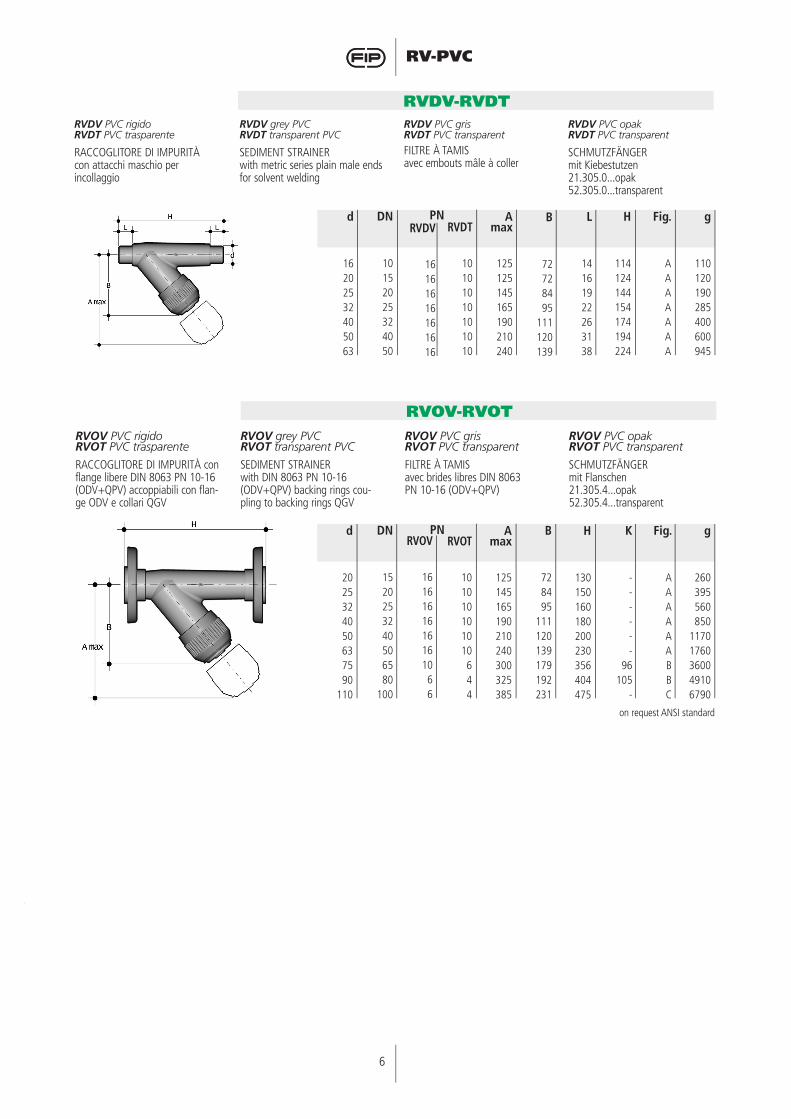
RVDV PVC rigido RVDT PVC trasparente
RACCOGLITORE DI IMPURITÀcon attacchi maschio per incollaggio
RVDV grey PVCRVDT transparent PVC
SEDIMENT STRAINERwith metric series plain male ends for solvent welding
RVDV PVC gris RVDT PVC transparent
FILTRE À TAMISavec embouts mâle à coller
RVDV PVC opak RVDT PVC transparent
SCHMUTZFÄNGERmit Kiebestutzen21.305.0...opak52.305.0...transparent
RVDV-RVDT
d
16202532405063
A max
125125145165190210240
RVDT
10101010101010
DN
10152025324050
B
72728495
111120139
L
14161922263138
H
114124144154174194224
Fig.
AAAAAAA
g
110120190285400600945
RVDV
16161616161616
PN
RVOV PVC rigidoRVOT PVC trasparente
RACCOGLITORE DI IMPURITÀ con flange libere DIN 8063 PN 10-16 (ODV+QPV) accoppiabili con flan-ge ODV e collari QGV
RVOV grey PVC RVOT transparent PVC
SEDIMENT STRAINER with DIN 8063 PN 10-16 (ODV+QPV) backing rings cou-pling to backing rings QGV
RVOV PVC grisRVOT PVC transparent
FILTRE À TAMISavec brides libres DIN 8063PN 10-16 (ODV+QPV)
RVOV PVC opak RVOT PVC transparent
SCHMUTZFÄNGERmit Flanschen21.305.4...opak52.305.4...transparent
RVOV-RVOT
d
2025324050637590
110
A max
125145165190210240300325385
RVOT
101010101010644
RVOV
1616161616161066
DN
1520253240506580
100
B
728495
111120139179192231
H
130150160180200230356404475
K
------
96105
-
Fig.
AAAAAABBC
g
260395560850
11701760360049106790
on request ANSI standard
PN

7
RV-PVC
1) Il raccoglitore può essere in-stallato in qualsiasi posizione avendo cura, però, che la frec-cia stampata sulla cassa indichi la direzione del fluido e che la parte filtrante sia rivolta verso il basso.
2) Qualora il raccoglitore venga installato verticalmente, se la giunzione avviene per incol-laggio, fare attenzione a che il collante non coli all’interno della cassa danneggiando così le parti interne. Per una cor-retta giunzione vedere le ap-posite istruzioni nel manuale “Elementi d’installazione”.
3) Per evitare danneggiamenti al-la retina, inserire sull’impianto apparecchiature atte ad evitare l’inversione del flusso.
1) The strainer may be installed in any position in the pipeline with the arrow on the body in the direction of the line flow and with the bonnet suspen-ded downwards.
2) When installing the strainer on a vertical line by solvent welding, extreme care must be taken to ensure that no solvent runs into the body as this would severely damage the internal parts and render the strainer inoperative. For correct jointing procedure refer to our section on “Installation”.
3) To eliminate any possible da-mage to the filter screen, pipe-line design should ensure that reverse flow conditions cannot occur.
1) Le filtre peut être installé dans n’importe quelle position horizontale aussi bien que verticale, en ayant soin que la fléche moulée sur le corps indique la direction du flux et que l’élément filtrant (tamis) soit orienté vers le bas.
2) Chaque fois que le filtre sera installé vericalement, si la
jonction est effectuée par col-lage, il faudra avoir soin que la colle ne coule pas à l’intérieur du corps. Pour une jonction correcte, voir les instructions sur le manuel “Eléments d’in-stallation”.
3) Afin de ne pas abimer le tamis il est opportun d’insérer sur l’installation un appareillage apte a éviter l’inversion du flux.
1) Die beiden Anschlußteile werden je nach Art auf die Rohrleitung geklebt oder auf-geschraubt
2) Schmutzfänger können in waagerechte und senkrechte Leitungen eingebaut werden. Achtung! Die Überwurfmutter muß dabei immer nach unten gerichtet sein.
3) Beim Einbau ist auf die Durchflußrichtung (Pfeil) zu achten. Ein Durchfluß in ent-gegengesetzter Richtung ist zu vermeiden, da das Filternetz zerstört werden kann.
Installazione sull’impianto
Connection to the system
Montage sur l’installation
Einbau in eine Leitung
Smontaggio Disassembly Démontage Demontage
FIG. A-C1) Isolare il raccoglitore dal flusso
del liquido e svuotare l’impian-to a monte dello stesso
2) Svitare la ghiera (7) e separare il coperchio-supporto (3-4) dal-la cassa (1)
3) Sfilare la rondella di fondo (6) dal coperchio-supporto (3-4)
4) Estrarre l’anello aperto (8) e separare la ghiera (7) dal co-perchio (3)
5) Estrarre l’O-ring di tenuta del coperchio (5)
FIG. B1) Isolare il raccoglitore dal flusso
del liquido e svuotare l’impian-to a monte dello stesso
2) Svitare il coperchio (3) e sepa-rano dalla cassa (1)
3) Sfilare il supporto (4) dal coper-chio (3)
4) Sfilare la rondella (6) dal coper-chio (3) e l’O-Ring (5) dalla sua sede nella cassa
FIG. A-C1) Isolate the strainer from the line
flow and drain down the entire upstream system
2) Unscrew the lock nut (7) and separate the bonnet assembly (3-4) from the body (1)
3) Remove the retaining ring (6) from the screen support (3-4)
4) Remove the split ring (8) to release the bonnet (3) from the lock nut (7)
5) Remove the bonnet sealing ring (5)
FIG. B1) Isolate the strainer from the line
flow and drain down the entire upstream system
2) Unscrew the bonnet (3) from the body (1)
3) Remove the screen support housing (4) from the bonnet
(3)4) Remove the retaining ring (6)
from the bonnet and the O-Ring seal (5) from its seat in the body (1)
FIG. A-C1) lsolez le filtre du fluide et vi-
dangez l’installation en amont de celui-ci
2) Dévissez la douille (7) et sépa-rez le couvercle-support (3-4) du corps (1)
3) Retirez la rondelle (6) du cou-vercle-support (3-4)
4) Extrayez la bague ouverte (8) et séparez la douille (7) du cou-vercle (3)
5) Extrayez l’O-ring d’étancheité (5) du couvercle (3).
FIG. B1) lsolez le filtre du flux du liquide
et vidangez la canalisation en amont
2) Dévissez le bouchon (3) qui doit être séparé du corps (1)
3) Retirez le support (4) du bou-chon (3)
4) Retirez le support (4) de son logement dans le corps (1)
5) Retirez la rondelle (6) du bou-chon (3) et le joint O-ring (5) de son logement dans le corps (1)
FIG. A-C1) Die Leitung ist an geeigneter
Stelle drucklos zu machen und zu entleeren
2) Nach dem Aufstecken der Überwurfmutter (7) auf das Oberteil (3) wird der Haltering (8) in die entsprechende Nut eingesetzt3) Danach ist das Filternetz (2)
in das Oberteil (3) einzusetzen und mit dem Ring (6) zu fixie-ren
4) Das kpl. Oberteil kann nun in das Gehäuse (1) gesteckt und mit der Überwurfmutter (7) angezogen werden
5) Der Haltering (8) ist vom Oberteil (3) abzuziehen, die Überwurfmutter wird hierdurch frei
6) Die O-Ring-Dichtung (5) kann jetzt entfernt werden
FIG. B1) Die Leitung ist an geeigneter
Stelle drucklos zu machen und zu entleeren
2) Das Unterteil (3) wird aus dem Gehäuse (1) herausgedreht
3) Das Einsteckteil (4) wird aus dem Unterteil (3) herausgezo-gen
4) Der Haltering (6) wird herau-sgenommen, das Filternetz (2) kann entfernt werden

8
RV-PVCMontaggio Assembly Montage Montage
FIG. A-C1) Inserire l’O-ring (5) nella sua
sede sul coperchio (3)2) Infilare il coperchio (3) nella
ghiera (7) e fissare i due com-ponenti per mezzo dell’anello aperto (8)
3) Infilare nel coperchio-supporto (3-4) la retina (2) e assicurarla con la rondella di fondo (6)
4) Inserire il coperchio (3) nella cassa (1) ed avvitare la
ghiera (7)
FIG. B1) Inserire l’O-Ring (5) nel corpo
(1)2) Inserire la rondella (6) nel co-
perchio (3)3) Inserire la retina (2) nel suo
supporto (4)4) Inserire il supporto (4) nel co-
perchio (3)5) Avvitare il coperchio (3) nella
cassa (1)
FIG. A-C1) Fit the O-ring (5) into the groo-
ve on the bonnet (3)2) Slip the lock nut (7) over the
bonnet and fix it in its position by snapping the split ring (8) into the top groove on the bon-net (3)
3) lnsert the filter screen (2) into the screen housing (3-4) and secure it with the retaining
ring (6)4) lnsert the bonnet (3) into the
body (1) and screw the lock nut (7)
FIG. B1) Fit the O-Ring seal (5) into the
body (1)2) Fit the retaining ring (6) into
the bonnet (3) with the cone shaped part upwards
3) lnsert the filter screen (2) in the screen support housing (4)
4) Insert the screen support housing (4) into the bonnet (3)5) Screw the bonnet assembly into the body (1)
FIG. A-C1) Placez l’O-ring (5) dans son
logement sur le couvercle-sup-port (3)
2) lnsérez le couvercle-support (3) dans la douille (7) et fixez les deux éléments au moyen de la bague ouverte (8)
3) lnsérez le tamis (2) dans le support (3-4)4) lnsérez le couvercle (3) dans le
corps (1) et vissez la douille (7)
FIG. B1) lnsérez le joint O-ring (5) dans
le corps (1)2) lnsérez la rondelle (6) dans le
bouchon (3)3) lnsérez le tamis (2) dans son
support (4)4) Insérez le support (4) dans le
bouchon (3)5) Vissez le bouchon (3) dans le
corps (1)
FIG. A-C1) Der O-Ring (5) ist in die Nut des
Oberteils (3) einzubringen2) Nach dem Lösen der
Überwurfmutter (7) kann das komplette Oberteil aus dem Gehäuse (1) gezogen werden
3) Danach ist das Filternetz (2) auf das Oberteil (3-4) einzusetzen und mit dem Ring (6) zu fixie-ren
4) Das Kpl. Oberteil kann nun in das Gehäuse (1) gesteckt und mit der Überwurfmutter ange-zogen werden
FIG. B1) Der O-Ring (5) wird in die
Gehäuse-Nut eingelegt2) Der Haltering (6) wird mit dem
konischen Teil nach außen in das Unterteil (3) eingelegt
3) Das Filternetz (2) wird in das Einsteckteil (4) geschoben
4) Das Einsteckteil (4) wird nun in das Unterteil (3) gesteckt
5) Die komplette Einheit wird nun in das Gehäuse (1) geschraubt und festgezogen.
AVVERTENZE• I raccoglitori con cassa traspa-
rente permettono il passaggio della luce provocando la crescita di alghe e microrganismi al loro interno
• I raccoglitori con cassa traspa-rente non sono protetti dall’ir-raggiamento solare. Un utilizzo in impianti all’aperto accelera il processo di invecchiamento del materiale riducendone il tempo di vita
• Si raccomanda di proteggere i raccoglitori con cassa trasparen-te da sollecitazioni vibrazionali in prossimità dei gruppi di pom-paggio
• Verificare sempre la pulizia degli elementi filtranti
WARNING• The sediment strainers with tran-
sparent body permit the light to come in causing the growth of seaweed and micro-organisms
• The sediment strainers with transparent body are not pro-tected against sun radiation. An openair use increases the ageing of the material and makes its lifetime shorter
• The sediment strainers whit tran-sparent body must be protected against vibrating stresses in proximity to pumping stations
• Always check the cleanness of the filtering elements
ATTENTION• Les filtres à tamis avec corps
transparent permettent au so-leil de faciliter la formation de micro organismes
• Les filtres à tamis ne sont pas protégés par les rayon solaires. Une utilisation en plein air accélère le viellisement des materiaux
• On recommende de proteger les filtres à tamis avec corps transparent des vibrations causées par les stations de pompage
• Nettoyer souvent les éléments du filtre
BEMERKUNG• Schmutzfänger mit transparen-
tem Gehäuse ermöglichen einen Lichteinfall in die Rohrleitung und hierdurch das Wachsen von Micro-Organismen
• Schmutzfänger mit transparen-tem Gehäuse sind nicht gegen Sonneneinstrahlung geschützt. Eine Freiluftinstallation beschleu-nigt die Alterung und verkürzt die Standzeit
• Schmutzfänger mit transparen-tem Gehäuse müssen gegen Vibration geschützt werden, besonders in Pumpenstationen.
• Der Verschmutzungsgrad der Filternetze ist regelmäßig zu überprüfen.
Le operazioni di manutenzione possono essere effettuate con il corpo valvola installato. Per effet-tuare queste operazioni è consi-gliabile lubrificare con olii e grassi idonei le parti soggette ad usura; a tale proposito si ricorda la non idoneità all’uso degli oli minerali, in quanto aggressivi per la gomma etilene-propilene.
Maintenance operations may be carried out with the strainer body in line. During maintenance ope-rations it is advisable to lubricate the rubber seals with grease. Do not use mineral oils as they attack EPDM rubber.
Les operations d’entretien peuvent être effectuées avec le corps du filtre installé. Pour effectuer ces opérations, il est conseillé de lu-brifier les éléments sujets à usure avec de l’huile. Il ne faut jamais utiliser des huiles minérales, etant agréssifs pour le caout-chouc éthylène-propylène.
Wartungsarbeiten können bei eingebautem Schmutzfänger durchgeführt werden. Bei der Montage werden die Dichtungen zweckmäßigerweise leicht mit Gummischmiermittel eingestrichen. Mineralenschmiermitteln sind nicht empofohlen, da sie den EPDM Gummi beschädigen.
9
RV-PVC
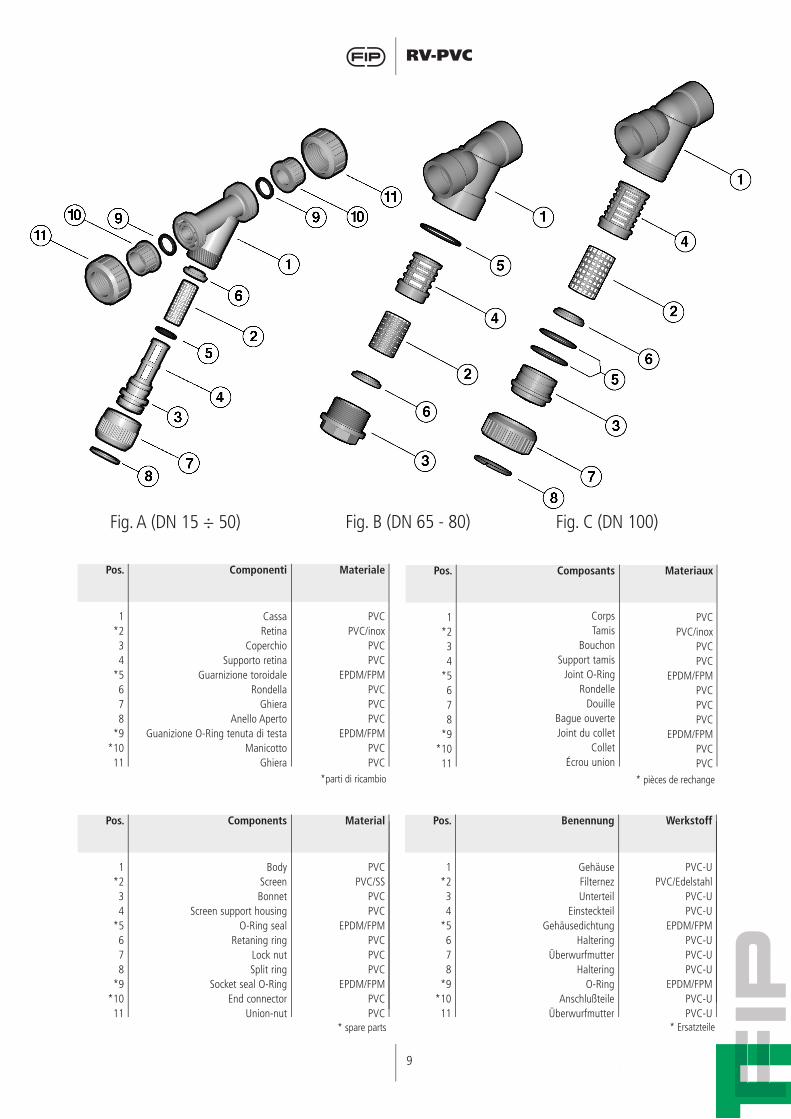
Pos.
1*2 34
*5678
*9*1011
Componenti
CassaRetina
CoperchioSupporto retina
Guarnizione toroidaleRondella
GhieraAnello Aperto
Guanizione O-Ring tenuta di testaManicotto
Ghiera
Materiale
PVCPVC/inox
PVCPVC
EPDM/FPMPVCPVCPVC
EPDM/FPMPVCPVC
*parti di ricambio
Pos.
1*2 34
*5678
*9*1011
Composants
CorpsTamis
BouchonSupport tamis
Joint O-RingRondelle
DouilleBague ouverteJoint du collet
ColletÉcrou union
Materiaux
PVCPVC/inox
PVCPVC
EPDM/FPMPVCPVCPVC
EPDM/FPMPVCPVC
* pièces de rechange
Pos.
1*2 34
*5678
*9*1011
Components
BodyScreenBonnet
Screen support housingO-Ring seal
Retaning ringLock nutSplit ring
Socket seal O-RingEnd connector
Union-nut
Material
PVCPVC/SS
PVCPVC
EPDM/FPMPVCPVCPVC
EPDM/FPMPVCPVC
* spare parts
Pos.
1*2 34
*5678
*9*1011
Benennung
GehäuseFilternezUnterteil
EinsteckteilGehäusedichtung
HalteringÜberwurfmutter
HalteringO-Ring
AnschlußteileÜberwurfmutter
Werkstoff
PVC-UPVC/Edelstahl
PVC-UPVC-U
EPDM/FPMPVC-UPVC-UPVC-U
EPDM/FPMPVC-UPVC-U
* Ersatzteile
Fig. A (DN 15 ÷ 50) Fig. B (DN 65 - 80) Fig. C (DN 100)