rwrg0073 - fault code 51 rail position sensor pre ...pub/@eaton/@roadranger/... · rwrg0073 - fault...
TRANSCRIPT
Pre-Authorized Warranty Repair Guideline RWRG0073
Page 103
RWRG0073 - Fault Code 51 Rail Position Sensor Pre-Authorization
OverviewThe X-Y Shifter is equipped with a Rail Position Sensor. The X-Y Rail Position Sensor reports lateral movement of the Shift Finger to the Transmission Electronic Control Unit (TECU) as a voltage signal. The X-Y Rail Position Sensor is connected to the TECU via the Transmission Harness.
The TECU performs continuous diagnostics on the circuit to detect a shorted circuit, open circuit or incorrect position reading. Fault Code 51 is set when the TECU has detected either an electrical failure of the X-Y Rail Position Sensor circuit or a mechanical failure within the X-Y Shifter.
Note: it has been determined that performing an electrical pre-test is not needed.
Symptom(s)• “F” flashes in gear display.
• Service light flashes (if equipped).
• Transmission remains in current gear.
• Until the fault becomes Inactive, driver may have to shut off engine with transmission in gear.
Warranty CoverageThis Warranty Repair Guideline repair DOES NOT apply if the Fault Code is Inactive and there are other Active Faults in the Eaton/OEM System. If there are other Active Faults, please fol-low normal troubleshooting procedure using the correct trou-bleshooting manual per transmission model.
This Pre-Authorization DOES NOT apply if the failed part has been replaced within the last 90 days on the truck.
The warranty coverage varies depending on vehicle vocation and transmission model type. Warranty coverage is the same as that of its respective transmission coverage including extended warranty.
Possible CausesFMI 2, 10
• Transmission Harness
• X-Y Shifter

Pre-Authorized Warranty Repair Guideline RWRG0073
Page 104
Component Identification
1. X-Y Shifter2. 3-Way Rail Position Sensor3. 3-Way Rail Position Sensor Connector4. 38-Way Transmission Harness Connector5. Transmission Electronic Control Unit (TECU)
1
5
2
4
3
Pre-Authorized Warranty Repair Guideline RWRG0073
Page 105
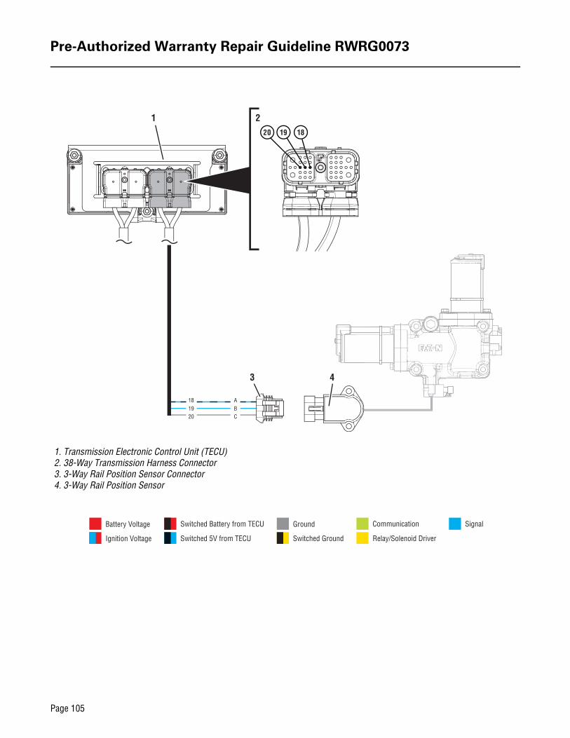
1. Transmission Electronic Control Unit (TECU)2. 38-Way Transmission Harness Connector3. 3-Way Rail Position Sensor Connector4. 3-Way Rail Position Sensor
181920
1 2
3 4
181920
ABC
SignalCommunication
Relay/Solenoid Driver
Ground
Switched Ground
Battery Voltage
Ignition Voltage
Switched Battery from TECU
Switched 5V from TECU

Pre-Authorized Warranty Repair Guideline RWRG0073
Page 106
Fault Code 51 Troubleshooting
1. Record the transmission fault codes, FMIs, occurrences, and timestamps from the Service Activity Report created during the Diagnostic Procedure.
Note: check history for X-Y Shifter replacement. If recent, replace harness
• If Fault Code 51 FMI 10 is Active, go to Step C.
• If Fault Code 51 FMI 10 is Inactive, go to Step B.
• If Fault Code 51 FMI 2 is Active or Inactive, go to Step D.
1. Set parking brake and chock wheels.
2. Place transmission in PD Mode.
Note: Transmission does not enter PD Mode when Active fault codes exist.
3. Wiggle wiring and connections of the Transmission Harness between the Rail Position Sensor and the TECU.
4. Exit PD Mode by powering down.
IMPORTANT: Allow 2–3 minutes for the TECU to per-form a complete power-down sequence before pro-ceeding.
• If any fault codes set Active while wiggling the Transmission Harness, replace Transmission Harness. Go to Step V.
• If no fault codes set Active while wiggling the Transmission Harness, go to Step C.
A Purpose: Check for Active or Inactive fault codes. B Purpose: Use Product Diagnostic (PD)
Mode to locate intermittent failures.
!
Pre-Authorized Warranty Repair Guideline RWRG0073
Page 107
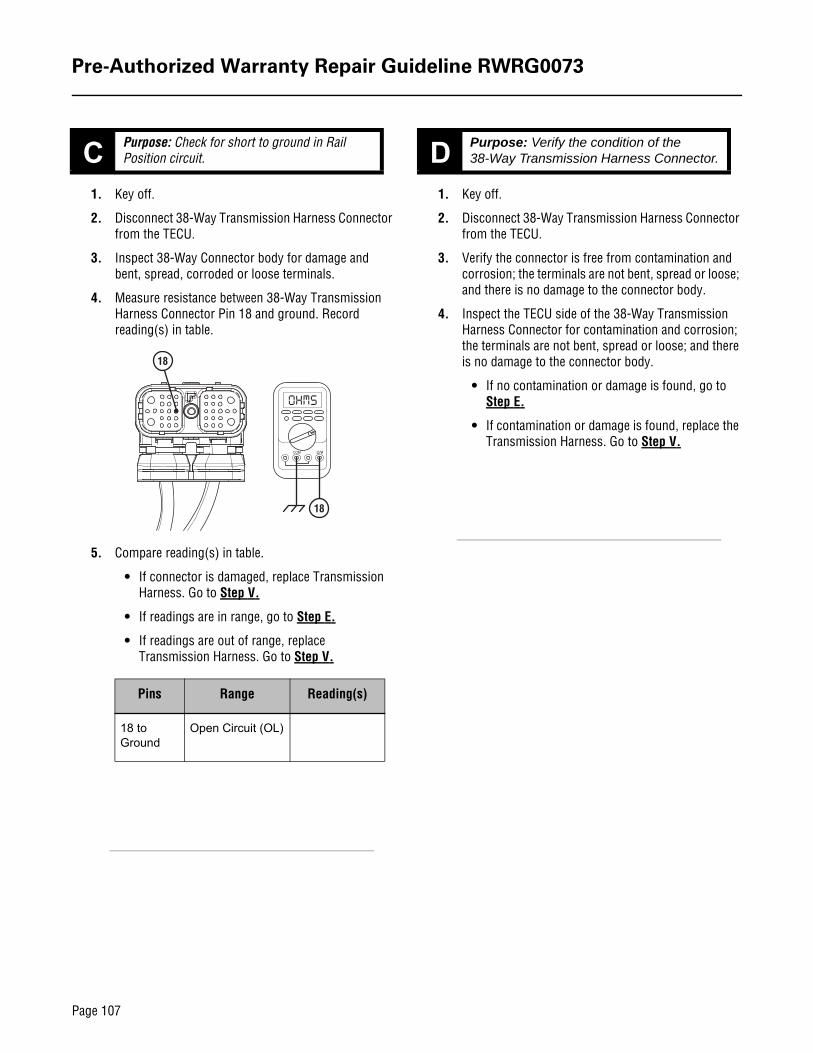
1. Key off.
2. Disconnect 38-Way Transmission Harness Connector from the TECU.
3. Inspect 38-Way Connector body for damage and bent, spread, corroded or loose terminals.
4. Measure resistance between 38-Way Transmission Harness Connector Pin 18 and ground. Record reading(s) in table.
5. Compare reading(s) in table.
• If connector is damaged, replace Transmission Harness. Go to Step V.
• If readings are in range, go to Step E.
• If readings are out of range, replace Transmission Harness. Go to Step V.
1. Key off.
2. Disconnect 38-Way Transmission Harness Connector from the TECU.
3. Verify the connector is free from contamination and corrosion; the terminals are not bent, spread or loose; and there is no damage to the connector body.
4. Inspect the TECU side of the 38-Way Transmission Harness Connector for contamination and corrosion; the terminals are not bent, spread or loose; and there is no damage to the connector body.
• If no contamination or damage is found, go to Step E.
• If contamination or damage is found, replace the Transmission Harness. Go to Step V.
C Purpose: Check for short to ground in Rail Position circuit.
Pins Range Reading(s)
18 to Ground
Open Circuit (OL)
18
18
D Purpose: Verify the condition of the 38-Way Transmission Harness Connector.
Pre-Authorized Warranty Repair Guideline RWRG0073
Page 108
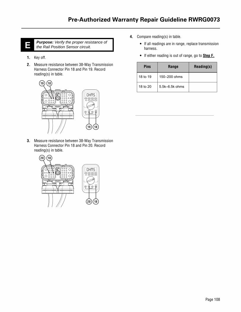
1. Key off.
2. Measure resistance between 38-Way Transmission Harness Connector Pin 18 and Pin 19. Record reading(s) in table.
3. Measure resistance between 38-Way Transmission Harness Connector Pin 18 and Pin 20. Record reading(s) in table.
4. Compare reading(s) in table.
• If all readings are in range, replace transmission harness.
• If either reading is out of range, go to Step F.
E Purpose: Verify the proper resistance of the Rail Position Sensor circuit.
1819
1819
1820
1820
Pins Range Reading(s)
18 to 19 150–200 ohms
18 to 20 5.5k–6.5k ohms

Pre-Authorized Warranty Repair Guideline RWRG0073
Page 109
1. Key off.
2. Disconnect 3-Way Transmission Harness Connector from 3-Way Rail Position Sensor.
3. Inspect 3-Way Connector body for damage and bent, spread, corroded or loose terminals.
4. Measure resistance between 3-Way Rail Position Sensor Body Pin A and Pin C. Record reading(s) in table.
5. Measure resistance between 3-Way Rail Position Sensor Body Pin A and Pin B. Record reading(s) in table.
6. Compare reading(s) in table.
• If the connector is damaged, replace Transmis-sion Harness. Go to Step V.
• If either reading is out of range, replace X-Y Shifter and Transmission Harness. Go to Step V.
1. Key off.
2. Reconnect all connectors and verify that all components are properly installed.
3. Key on with engine off.
4. Clear fault codes using ServiceRanger.
5. Drive vehicle and attempt to reset the code or duplicate the previous complaint.
6. Check for fault codes using ServiceRanger.
• If no fault codes set Active and the vehicle operates properly, test complete.
• If Fault Code 51 sets Active during the test drive, utilize roadranger.com for further troubleshooting options.
• If a fault code other than 51 sets Active, trouble-shoot using appropriate troubleshooting manual.
F Purpose: Measure the resistance of the Rail Position Sensor.
AC
C
A
AB
A
B
Pins Range Reading(s)
A to B 150–200 ohms
A to C 5.5k–6.5k ohms
V Purpose: Verify repair.

Pre-Authorized Warranty Repair Guideline RWRG0073
Page 110
Warranty Parts• X-Y Shifter
• Transmission Harness
Warranty Labor• Diagnostics - 0.5 hr
• Check Codes - 0.3 hr
• Software Update if not current version - 0.5 hr
• SRT X-Y Shifter R&R If Required in Troubleshooting
• SRT Transmission Harness R&R
Warranty Coding• Failed Part #: Harness or XY Shifter Kit Number
• Complaint Code: STUCK IN GEAR
• Failure Code: ROOT CAUSE NOT DETERMINED
Warranty Claim Filing
File pre-authorized warranty claim through appropriate OEM or through Direct Pay.
• RWRG0073
• OEM Warranty Coverage
• Software Revision (from and to)
Note: Repairs that exceed parts and labor parameters cannot be pre-authorized.
Filing through Direct Pay
Click here for Direct Pay submission guidelines and claim forms:
Parts Disposition
Return All Parts Per OEM or Direct Pay Guidelines
Warranty Disclaimer
If the failure is not the result of an accident, damage, negli-gence, abuse or misuse, improper installation or maintenance or any other conditions described in the Limits and Exclusions section of the Eaton Warranty Manual TCWY0600, then Eaton will treat the condition as covered under its warranty. How-ever, this conclusion does not necessarily mean that a defect in fact exists. In all cases, Eaton shall make the final determi-nation and interpretation as to the warrantability of the prod-uct.
Submission Guidelinesand Claim Forms