rwz e 04 2017 • © frenco gmbh · the two gears are detected and form the basis ... - mahr 894b,...
TRANSCRIPT
RWZ E 04 2017 • © Frenco GmbH

2
The basic principle of the double flank gear roll inspection is that a master gear (nearly perfect gear) and a workpiece gear are meshing free from backlash. One axis of rotation is mounted firmly and the other is mounted in a floating manner. The variations in distance when rolling the two gears are detected and form the basis for the evaluation of the gear profile with respect to the existing composite error caused by pro-duction.
When used with modern evaluation solutions such as a PC, hardware and software, the double flank gear roll inspection proves to be an effi-cient means of controlling the quality in a quick and easy way.
General Information
Advantages of FRENCO’s double flank gear roll inspection machines:
Stable machines for the shop floor use.
Customer-specific design: The machines are perfectly adjusted to the specimen to be measured
and to the conditions of measurement.
The measuring force is infinitely variable.
Rapid lift-off of the measurement carriage.
Using non-rotating tips and mounting mandrels, the runout deviation is kept low.
Special master gear pair for calibration.
With the evaluation software 'FGI pro' being in-house developed, quick support is available should
any issues arise.
The master gears are manufactured in-house at FRENCO in Altdorf, Germany.
On request, we can upgrade older double flank gear roll inspection machines with FRENCO meas-
urement electronics and the FGI evaluation software.
3
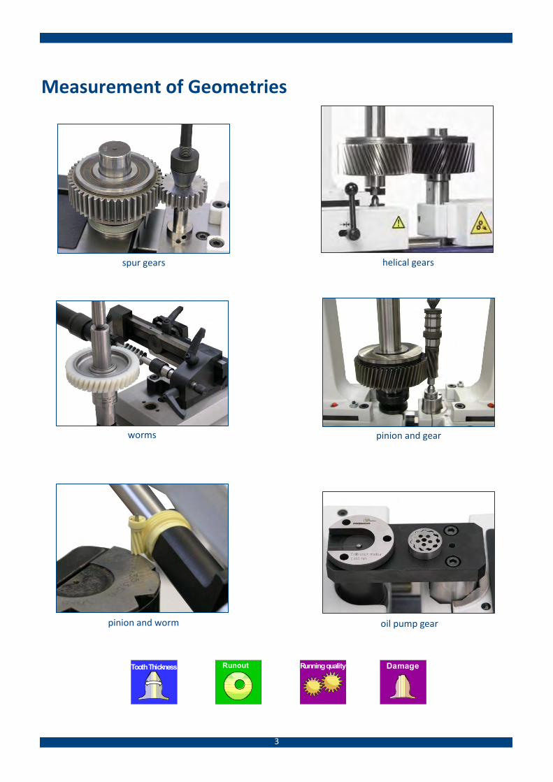
Measurement of Geometries
spur gears
worms
oil pump gear pinion and worm
pinion and gear
helical gears
Tooth Thickness Runout Running quality Damage
4
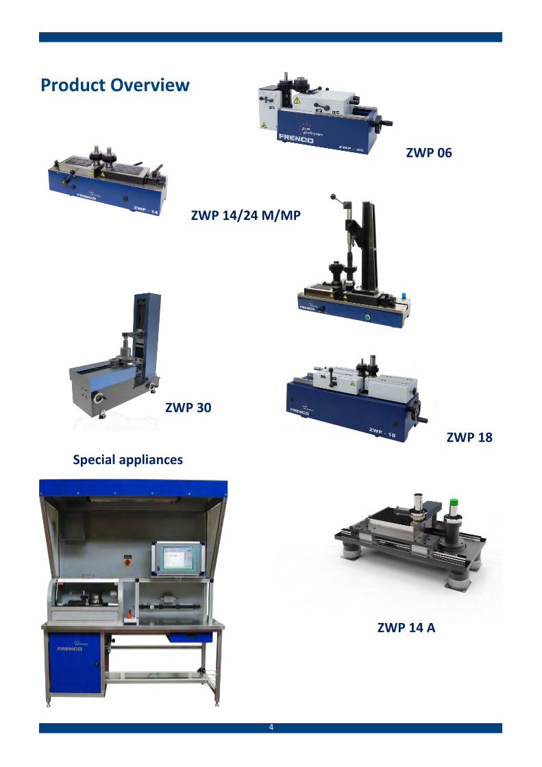
Product Overview
ZWP 14/24 M/MP
ZWP 06
ZWP 30
ZWP 18
Special appliances
ZWP 14 A
5
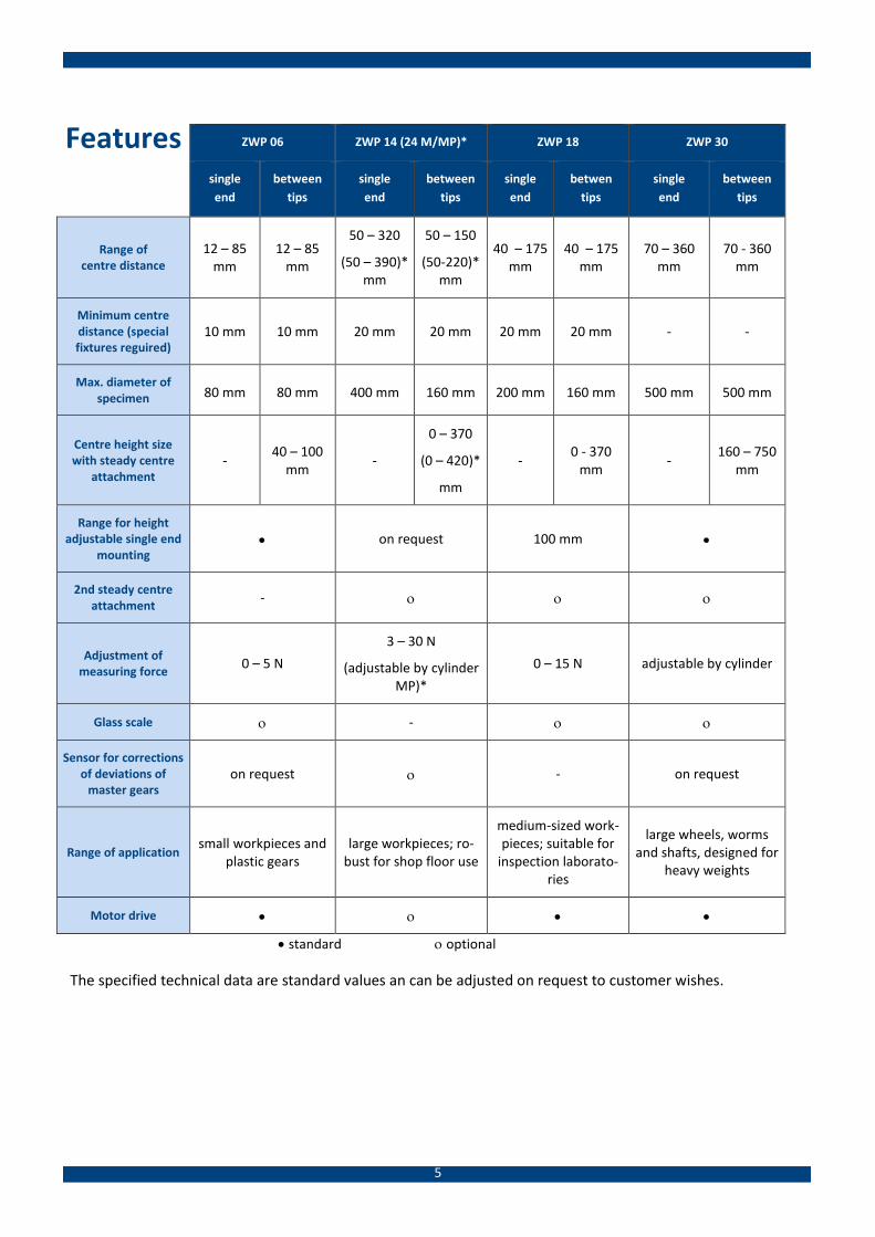
Features ZWP 06 ZWP 14 (24 M/MP)* ZWP 18 ZWP 30
single
end
between
tips
single
end
between
tips
single
end
betwen
tips
single
end
between
tips
Range of centre distance
12 – 85 mm
12 – 85 mm
50 – 320
(50 – 390)* mm
50 – 150
(50-220)* mm
40 – 175 mm
40 – 175 mm
70 – 360 mm
70 - 360 mm
Minimum centre distance (special fixtures reguired)
10 mm 10 mm 20 mm 20 mm 20 mm 20 mm - -
Max. diameter of specimen 80 mm 80 mm 400 mm 160 mm 200 mm 160 mm 500 mm 500 mm
Centre height size with steady centre
attachment -
40 – 100 mm
-
0 – 370
(0 – 420)*
mm
- 0 - 370
mm -
160 – 750 mm
Range for height adjustable single end
mounting on request 100 mm
2nd steady centre attachment
-
Adjustment of measuring force
0 – 5 N
3 – 30 N
(adjustable by cylinder MP)*
0 – 15 N adjustable by cylinder
Glass scale -
Sensor for corrections of deviations of
master gears on request - on request
Range of application small workpieces and
plastic gears large workpieces; ro-
bust for shop floor use
medium-sized work-pieces; suitable for
inspection laborato-ries
large wheels, worms and shafts, designed for
heavy weights
Motor drive
standard optional
The specified technical data are standard values an can be adjusted on request to customer wishes.
6
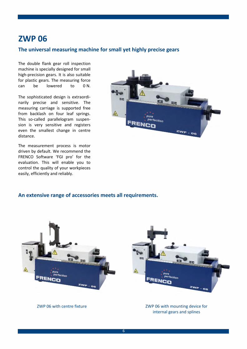
ZWP 06 The universal measuring machine for small yet highly precise gears
The double flank gear roll inspection machine is specially designed for small high-precision gears. It is also suitable for plastic gears. The measuring force can be lowered to 0 N. The sophisticated design is extraordi-narily precise and sensitive. The measuring carriage is supported free from backlash on four leaf springs. This so-called parallelogram suspen-sion is very sensitive and registers even the smallest change in centre distance.
The measurement process is motor driven by default. We recommend the FRENCO Software ‘FGI pro’ for the evaluation. This will enable you to control the quality of your workpieces easily, efficiently and reliably.
ZWP 06 with centre fixture ZWP 06 with mounting device for internal gears and splines
An extensive range of accessories meets all requirements.
7
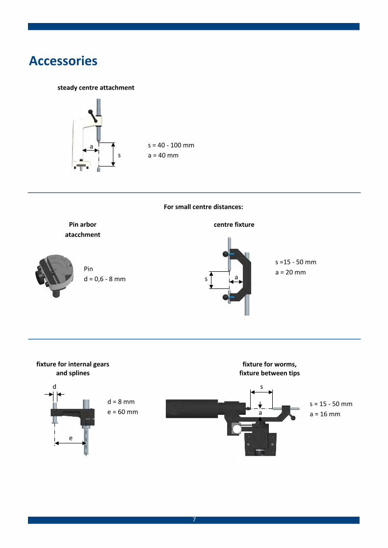
Accessories
Pin arbor
atacchment
steady centre attachment
centre fixture
s = 40 - 100 mm
a = 40 mm
Pin
d = 0,6 - 8 mm
s =15 - 50 mm
a = 20 mm
fixture for worms, fixture between tips
d = 8 mm
e = 60 mm
fixture for internal gears and splines
s = 15 - 50 mm
a = 16 mm
a s
a
s d
e
a s
For small centre distances:
8
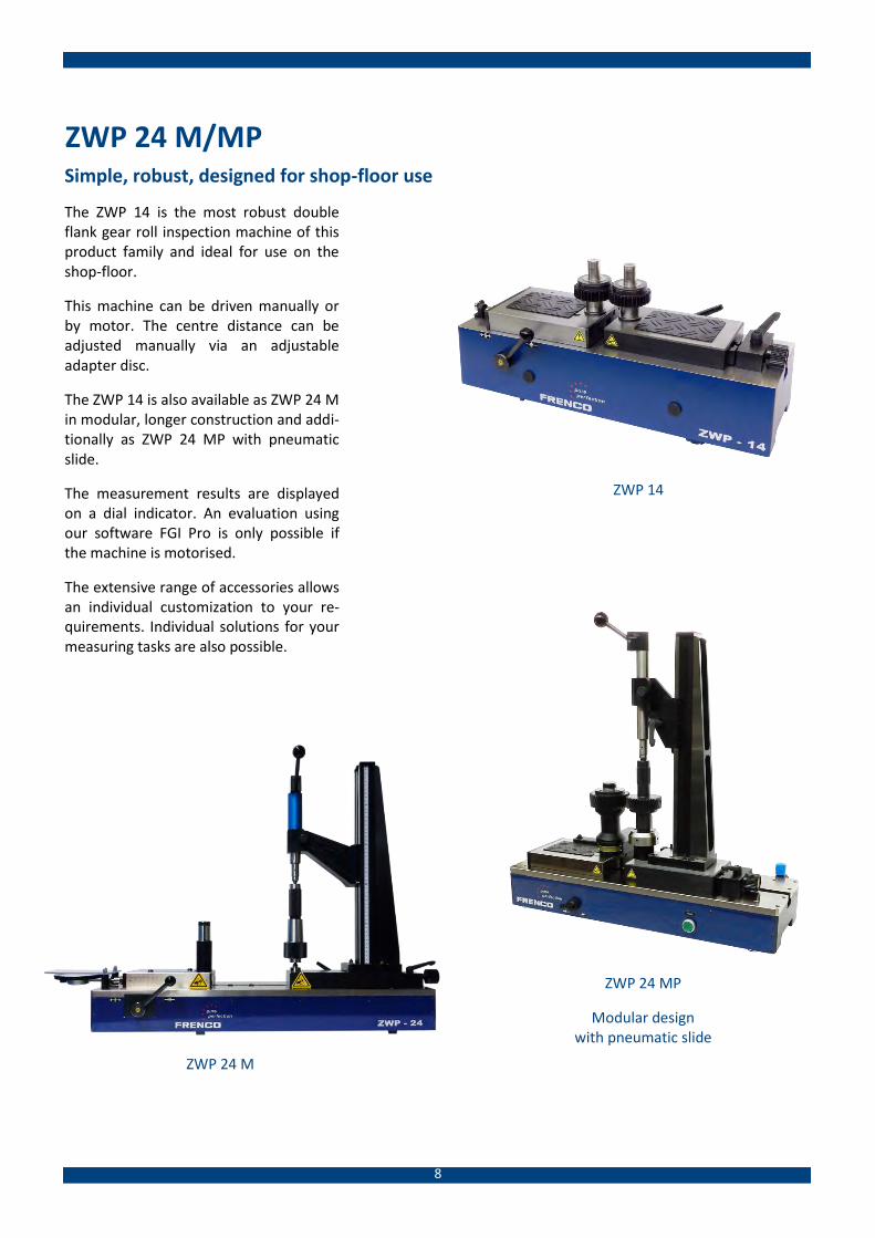
ZWP 24 M/MP Simple, robust, designed for shop-floor use
The ZWP 14 is the most robust double flank gear roll inspection machine of this product family and ideal for use on the shop-floor.
This machine can be driven manually or by motor. The centre distance can be adjusted manually via an adjustable adapter disc.
The ZWP 14 is also available as ZWP 24 M in modular, longer construction and addi-tionally as ZWP 24 MP with pneumatic slide.
The measurement results are displayed on a dial indicator. An evaluation using our software FGI Pro is only possible if the machine is motorised.
The extensive range of accessories allows an individual customization to your re-quirements. Individual solutions for your measuring tasks are also possible.
ZWP 24 M
ZWP 24 MP
Modular design with pneumatic slide
ZWP 14

9
Accessories
steady centre attachment small
sMAX = 370 mm
a = 82 mm
a = 80 mm
sMAX = 420 mm
a = 160 mm
a = 80 mm
steady centre attachment large
a s
a s
Adapter for small centre distances: centre fixture
sMAX = 140 mm
a = 46 mm
a = 45 mm
Fixture for worms, mounting between tips
Fixture for worms, mounting trough prisms
(bearing seat as reference) sMAX = 150 mm w = ±45°
a = 40 mm
a = 40 mm
sMAX = 250 mm
a = 40 mm
a = 40 mm
s
a w a
s
Adapter for small centre distances: Pin arbor attachment
pin d = 1-16 mm
Fixture for worms, height adjustable through crank handle, fixed version
Fine adjustment
pin d = 4-22 mm
Stro
ke =
10
0 m
m
Adjustable quill

10
ZWP 18 Highest precision and comfortable handling
The high quality ZWP 18 features a so-phisticated setup and allows high preci-sion measurements.
The centre distance can be changed easi-ly and quickly by adjusting the measuring carriage with a hand-wheel. The adjusta-ble mandrel allows simple and conven-ient adjustment of the height of the gears to be inspected. Many accessory items can easily be attached to the in-strument.
The drive is integrated into the device. To ensure highest precision, the measuring carriages are mounted on very smooth guideways.
ZWP 18 with worm inspection fixture ZWP 18 with steady centre attachment
11
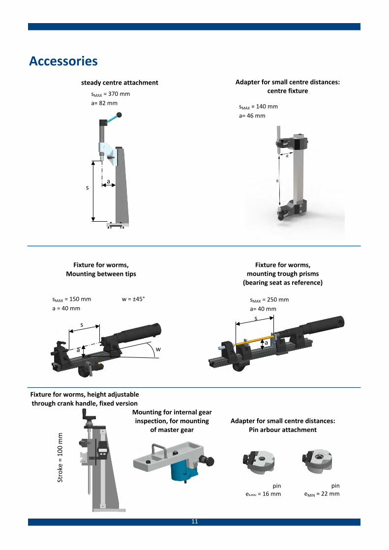
Accessories
steady centre attachment
sMAX = 370 mm
a= 82 mm
a = 80 mm
a s
Adapter for small centre distances: centre fixture
Fixture for worms, Mounting between tips
sMAX = 150 mm w = ±45°
a = 40 mm
a = 40 mm
Adapter for small centre distances: Pin arbour attachment
pin eMIN = 16 mm
pin eMIN = 22 mm
Mounting for internal gear inspection, for mounting
of master gear
Fixture for worms, mounting trough prisms
(bearing seat as reference)
sMAX = 250 mm
a= 40 mm
a = 40 mm s
a w a
s
Fixture for worms, height adjustable through crank handle, fixed version
Stro
ke =
10
0 m
m
sMAX = 140 mm
a= 46 mm
a = 45 mm
12
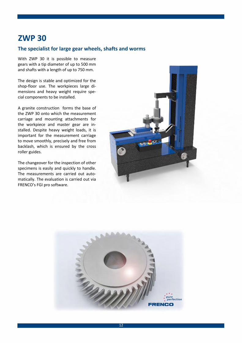
ZWP 30 The specialist for large gear wheels, shafts and worms
With ZWP 30 it is possible to measure gears with a tip diameter of up to 500 mm and shafts with a length of up to 750 mm. The design is stable and optimized for the shop-floor use. The workpieces large di-mensions and heavy weight require spe-cial components to be installed. A granite construction forms the base of the ZWP 30 onto which the measurement carriage and mounting attachments for the workpiece and master gear are in-stalled. Despite heavy weight loads, it is important for the measurement carriage to move smoothly, precisely and free from backlash, which is ensured by the cross roller guides. The changeover for the inspection of other specimens is easily and quickly to handle. The measurements are carried out auto-matically. The evaluation is carried out via FRENCO’s FGI pro software.

13
Software „FGI pro“ The software FGI pro includes both, the control of the drive and the evaluation of data. The software is in-house developed and programmed by our specialists for applications software. With the actual values being marked in colour, the specimen can quickly be evaluated as ‘Pass’ (green) or ’Fail’ (red).
Further software properties:
Easy input and amending of inspection options
After the inspection, the workpiece will be turned to the position of maximum deviation (values are se-lectable)
Language features: - German, English, Spanish, French, Portuguese, Polish, Hungarian and Chinese are available - Program language and output language can be selected separately (Unicode support) - Easy data exchange when corporate languages are different
Archiving function: every single measurement data is saved
Central, statistical analysis due to interfaces (qs-STAT ®, CASQ-it 9000 and internal Ethernet-systems)
The software determines the following values: - total radial composite deviation Fi'' - tooth-to-tooth radial composite deviation fi'' - runout deviation by composite test Fr'' - short-wave component fk''
Additionally, when machine has been calibrated: - centre distance Aa'' - dimension over balls MdK - tooth thickness Sn - span size Wk.
Polar chart
Visualized Fourier spectrum

14
Retrofit FRENCO retrofits earlier double flank gear roll inspection testers with the powerful measuring electronics MEG 32 and the evaluation software FGI pro. The retrofit is possible for all below mentioned machine types. No matter if they ran until now with manual evaluation, pen recorder or earlier electron-ics.
For retrofitting, please send the machine to FRENCO GmbH. The device will be dismantled, cleaned and smaller repairs will be carried out. Furthermore, probe and motor will be replaced and an emergency-stop button will be in-stalled (unless one is already installed).
The double flank gear roll tester will be completely refurbished!
The following devices can be retrofitted:
- Mahr 894B, 896B, 898B, 898C - Hommel ZWG8305, ZWG8315 - Höfler ZW300 - other types on request
Höfler ZW300 after retrofitting
Hommel ZWG 8305 after retro-
fitting
Höfler ZW300 before retrofitting
15
Centre Distance Inspection
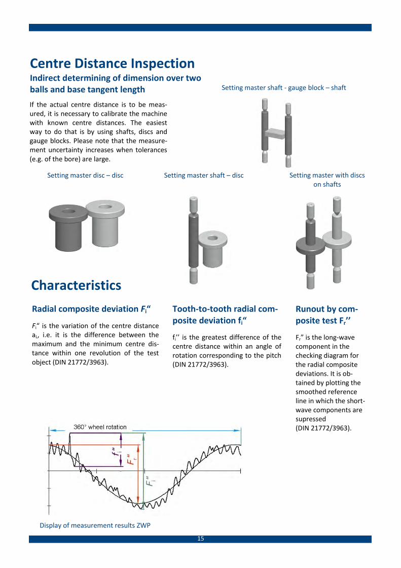
Indirect determining of dimension over two balls and base tangent length Setting master shaft - gauge block – shaft
If the actual centre distance is to be meas-ured, it is necessary to calibrate the machine with known centre distances. The easiest way to do that is by using shafts, discs and gauge blocks. Please note that the measure-ment uncertainty increases when tolerances (e.g. of the bore) are large.
Setting master with discs on shafts
Setting master disc – disc
Setting master shaft – disc
Characteristics
Radial composite deviation Fi“
Fi“ is the variation of the centre distance aL, i.e. it is the difference between the maximum and the minimum centre dis-tance within one revolution of the test object (DIN 21772/3963).
Tooth-to-tooth radial com-posite deviation fi“
fi’’ is the greatest difference of the centre distance within an angle of rotation corresponding to the pitch (DIN 21772/3963).
Runout by com-posite test Fr’’
Fr” is the long-wave component in the checking diagram for the radial composite deviations. It is ob-tained by plotting the smoothed reference line in which the short-wave components are supressed (DIN 21772/3963).
Messwertedarstellung ZWP
Display of measurement results
Display of measurement results ZWP

16
Traceability
The Physikalisch-Technische Bundesanstalt (PTB, the national metrology institute in Germany) does not offer traceability for double flank gear rolling inspection pa-rameters. This means that the PTB does not calibrate Fi’’, fi’’, Fr’’ or fk’’.
FRENCO is probably the only company worldwide that is able to calibrate the gear and double flank gear rolling tester parameters Fi’’, fi’’, Fr’’ and fk’’.
To this end, a highly precise limit calibration set MPE, consisting of 5 master gears, was measured under cali-bration conditions approxi-mately 2,000 times on 75 different double flank gear rolling testers from around the world.
All measurement results were analysed using statisti-cal methods, rogue results eliminated and arithmetic mean values and interven-tion limits calculated.
Finally, the calibration val-ues Fi’’, fi’’, Fr’’, fk’’ and the measurement uncertainties UFi’’, Ufi’’, UFr’’ and Ufk’’ can now be calculated using these values.
There are 12 such limit cali-bration sets MPE world-wide, five of which, with various geometries, are held by FRENCO.
The principle for determining the calibration values
and measurement uncertainties
Fi‘‘
fi‘‘
...
Fi‘‘ fi‘‘, fe‘‘,
fk‘...
...
Limit calibration set MPE
Calibration of numerous double flank gear rolling testers
Statistical analysis
Calibration values and measurement uncertainties
What is it used for?
- Calibration of Double Flank Gear Rolling Testers (ZWP)
- Evaluation of ZWP
- Determination of measurement uncertainty of ZWP
- Conformity assessment (Fail/Pass)

17
Calibration set MPE
Fr” - master for
long wave portions
fi’’- master for short wave portions
reference master
setting master
centre distance
check master
linearity
A complete calibration of double flank gear roll inspection ma-chines is only possible with a limit calibration set MPE. Such a set consists of 5 master gears. The reference master gear is the reference gear. It has got no mod-ifications. Tooth No. 1 is marked. The four other master gears are rolled, measured and logged against tooth 1. The Fr” - master has got a radial run-out which presents itself as a long-wave sinusoidal Fr’’ devia-tion. The fi” - master has got variations in tooth thickness, which cause a short-wave fi’’ deviation. The centre distance is calibrated with the setting master centre distance. The check master has got a differ-ing tooth thickness from that of the setting master centre dis-tance. The deviation of the centre distance thereby caused has got a nominal size, which should pre-sent itself as the actual size during calibration. Deviations in the scale and linearity can thus be detect-ed. After every final inspection, maintenance and service a cali-bration certificate is issued con-taining all deviations. This certificate can be used as the basis for wear inspections, audits and certifications.
18
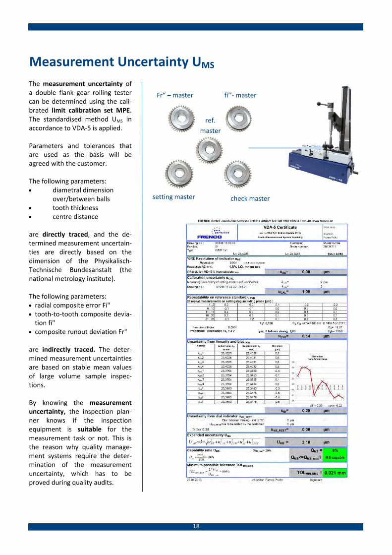
Measurement Uncertainty UMS
The measurement uncertainty of a double flank gear rolling tester can be determined using the cali-brated limit calibration set MPE. The standardised method UMS in accordance to VDA-5 is applied. Parameters and tolerances that are used as the basis will be agreed with the customer.
The following parameters: diametral dimension
over/between balls tooth thickness centre distance are directly traced, and the de-termined measurement uncertain-ties are directly based on the dimension of the Physikalisch-Technische Bundesanstalt (the national metrology institute). The following parameters: radial composite error Fi" tooth-to-tooth composite devia-
tion fi" composite runout deviation Fr" are indirectly traced. The deter-mined measurement uncertainties are based on stable mean values of large volume sample inspec-tions. By knowing the measurement uncertainty, the inspection plan-ner knows if the inspection equipment is suitable for the measurement task or not. This is the reason why quality manage-ment systems require the deter-mination of the measurement uncertainty, which has to be proved during quality audits.
Fr“ – master fi’’- master
ref.
master
setting master check master
19
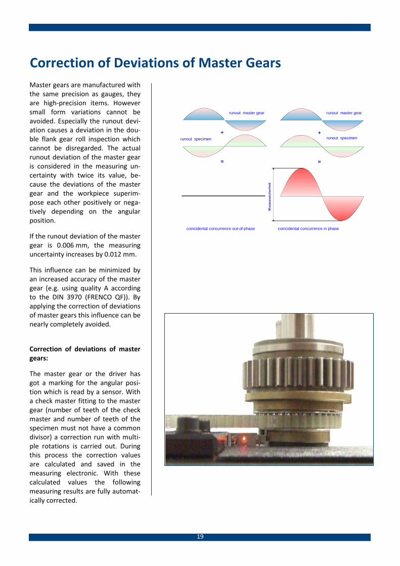
Correction of Deviations of Master Gears
Master gears are manufactured with the same precision as gauges, they are high-precision items. However small form variations cannot be avoided. Especially the runout devi-ation causes a deviation in the dou-ble flank gear roll inspection which cannot be disregarded. The actual runout deviation of the master gear is considered in the measuring un-certainty with twice its value, be-cause the deviations of the master gear and the workpiece superim-pose each other positively or nega-tively depending on the angular position.
If the runout deviation of the master gear is 0.006 mm, the measuring uncertainty increases by 0.012 mm.
This influence can be minimized by an increased accuracy of the master gear (e.g. using quality A according to the DIN 3970 (FRENCO QF)). By applying the correction of deviations of master gears this influence can be nearly completely avoided.
Correction of deviations of master gears:
The master gear or the driver has got a marking for the angular posi-tion which is read by a sensor. With a check master fitting to the master gear (number of teeth of the check master and number of teeth of the specimen must not have a common divisor) a correction run with multi-ple rotations is carried out. During this process the correction values are calculated and saved in the measuring electronic. With these calculated values the following measuring results are fully automat-ically corrected.
+
=
+
=
Mes
suns
iche
rhei
t
Rundlauf Lehrzahnrad
Rundlauf Prüfling Rundlauf Prüfling
Rundlauf Lehrzahnrad
Zufälliges Zusammentreffen phasenverschoben Zufälliges Zusammentreffen phasengleich
runout master gear runout master gear
runout specimen runout specimen
coincidental concurrence out-of-phase coincidental concurrence in phase

Frenco Product Range
Frenco GmbHGear + Spline TechnologyJakob-Baier-Straße 390518 Altdorf, GermanyTel.: +49 (0) 9187 - 95 22 0Fax: +49 (0) 9187 - 95 22 40E-Mail: [email protected]
www.frenco.de
High Precision Gears and Splines H
Gear and Spline Gauges
Master Gears, Master Wheels
Artefacts, Masters
Punches, Dies & Electrodes
Profiled Clamping Systems
Gear and Spline Manufacture
Instruments for Size Inspection Series V
Measuring Pins and Ball Inserts
Instruments, Rocking Type
Instruments with Face Stop
Instruments with Guiding Profiles
Circumferential Backlash Instrument
Customized Solutions
Rotation Measuring Systems R
Instruments with Measuring Circles
Multiple Inspector
Gear Flank Analysing Linear Gear Flank Analyser Rack Gear Flank Analyser Double Flank Gear Roll Inspection
Gear & Spline Inspection P
DAkkS -Calibration
Monitoring of Inspection Equipment
Workpiece Inspections
Analysis of Deviations
Know-How-Transfer K
Software
Training, Seminars, Workshops
Consulting and Calculations
Literature and Documentations
National and International Standards