ryan: rendering your animation nonlinearly projectedpatrick/papers/ryannpar2004/ryanpaper.pdf ·...
TRANSCRIPT

RYAN: Rendering Your Animation Nonlinearly projected
Patrick Coleman∗ Karan Singh†
University of Toronto
Abstract
Artistic rendering is an important research area in Computer Graph-ics, yet relatively little attention has been paid to the projectiveproperties of computer generated scenes. Motivated by the sur-real storyboard of an animation in production—Ryan—this paperdescribes interactive techniques to control and render scenes us-ing nonlinear projections. The paper makes three contributions.First, we present a novel approach that distorts scene geometry suchthat when viewed through a standard linear perspective camera, thescene appears nonlinearly projected. Second, we describe a frame-work for the interactive authoring of nonlinear projections definedas a combination of scene constraints and a number of linear per-spective cameras. Finally, we address the impact of nonlinear pro-jection on rendering and explore various illumination effects. Thesetechniques, implemented in Maya and used in the production of theanimation Ryan, demonstrate how geometric and rendering effectsresulting from nonlinear projections can be seamlessly introducedinto current production pipelines.
CR Categories: I.3.3 [Computer Graphics]: Image Generation—Viewing Algorithms; I.3.5 [Computer Graphics]: Three-Dimensional Graphics and Realism—Animation
Keywords: Non-Photorealistic Rendering, Multiprojection, Non-linear Perspective, Local Illumination
1 Introduction
Artists using traditional media almost always deviate from the con-fines of a precise linear perspective view. Many digital artists, how-ever, continue to struggle with the standard pinhole camera modelused in Computer Graphics to generate expressive 2D images of3D scenes. The history of the use of linear perspective in art out-lined in Figure 2 provides good insight into its benefits and limita-tions. Even though the earliest documented observation of perspec-tive has been dated to approximately 4000 B.C., renderings of 3Dscenes as late as 1400 lack depth and show clear perspective errors,as can be seen on the tower in an illustration from the KaufmannHaggadah. Artists in the early 1400s, beginning with Brunelleschi,used mirrors, camera obscura, and other optical devices to aid theirunderstanding of perspective. This understanding was reflected inart until the 20th century, when inspired by the theory of relativity,
∗e-mail: [email protected]†e-mail: [email protected]
Figure 1: A nonlinear projection rendering from Ryan, designedwith our interactive system
artists such as Picasso broke from the confines of linear perspectiveto integrate the temporal view of a scene as a nonlinear projection.
Linear perspective has the primary advantage of being a simpleand approximate model of the projections associated with both realcameras and the human visual system. The model also providessimple, consistent, and easily understood depth cues to the spa-tial relationships in a three-dimensional scene. From a mathemati-cal standpoint, the pinhole camera model is a linear transformationthat provides an efficient foundation for current graphics pipelineswithin which rendering issues such as clipping, shadowing, and il-lumination are well understood. While a linear perspective view isa robust medium for viewing localized regions of a scene, it canbe restrictive for the visualization of complex shapes and environ-ments.
This work has been inspired by two pieces of concept artworkfrom the animated production Ryan, in which deviations from lin-ear perspective are used to convey cinematic mood and a character’sstate of mind. Given that humans have a strong mental sense of lin-ear perspective, subtle variations in perspective provide an animatorwith the ability to generate a sense of uneasiness in the audience toreflect the mood within the animated environment. Larger devia-tions from a linear perspective can be used to affect the sense ofspace or convey a feeling of lightness in the animation. Figure 3 isa preproduction sketch, and like most artwork created before 1400,shows a mix of projections used to view different parts of a scene.Figure 4 is an artist-created composite image of 3D deformationsand multiple projections of the same scene. Evident in these twoconcept pieces are the qualities of global scene coherence and localdistortions of geometry and shading resulting from changes in per-spective. These characteristics become the design principles for ourapproach to representing nonlinear projections as a combination ofdistortion-inducing linear perspective cameras and constraints thatmaintain global scene coherence.
In addition to this visual characterization, the authoring approachshould be intuitive to an animator experienced with conventional

Figure 2: History of perspective in art
methods of animating a single linear perspective camera. Whileviewing the scene through this primary camera, the animator shouldthus be able to add or remove scene distorting cameras that turn theprimary camera view into a nonlinear projection. As the nonlinearprojections need not be applied to all scene elements, the animatorneeds the ability to interactively specify various scene constraintsto preserve overall scene coherence and to create a desired shotcomposition.
We now present a brief description of how our nonlinear projec-tion system fits these problem characteristics. A conventional ani-mation workflow uses a single perspective camera for setting up andanimating a shot: we refer to this as the boss camera. Lackey cam-eras are added as needed to represent different target linear viewsof scene elements. The animator can chain lackey cameras to spec-ify a projective path from the boss camera view to the target view.The parts of a scene that a particular lackey camera influences willbe deformed to appear in the boss camera view as though viewedby that lackey camera. The animator can also add constraints onthe position, size, and depth of deformed parts of a scene to bettercontrol composition. Finally, the animator can control the resultingillumination and shading of the scene as a combination of render-ing parameters of the boss and lackey cameras. Illumination withrespect to the single view of the boss camera ignores effects of thealternate views. This results in an appearance discrepancy betweenthe local regions of the nonlinearly projected image and the linearperspective projections used by the animator to define the nonlinearprojection. We introduce two methods for incorporating the mul-tiple views into illumination calculations, and compare these withthe single view illumination model. While both are appropriate, weargue for the use of the model that is both more predictable withrespect to controlling multiple linear perspective cameras and has
Figure 3: Preproduction artwork for Ryan incorporating an artisticcombination of projection techniques
stylistically similar effects to those of nonlinear projection (Fig-ure 5).
This paper presents the design and implementation of these con-cepts within the animation system Maya, thus making three con-tributions. First, we present an approach to interactively distortingscene geometry so that when viewed through a standard linear per-spective camera, the scene appears nonlinearly projected. Second,we describe a framework that integrates multiple linear perspectiveviews with scene constraints into a single nonlinear projection ofthe scene. Third, we address the impact of nonlinear projection onrendering and explore various illumination effects.
1.1 Previous Work
Researchers have applied nonlinear projection in computer gener-ated imagery for a variety of purposes. These include image warp-ing, 3D projections, and multi-perspective panoramas. Singh[2002]presents a good survey, but does not describe how these approachesaddress rendering aspects such as clipping, shadows, and illumina-tion of nonlinearly projected scenes. We give an overview of thishere, followed by a discussion of the work of Agrawala et. al.[2000]and Singh[2002], which is of most relevance to this paper.
Image warping techniques[Fu et al. 1999] are inherently two-dimensional approaches with limited ability to explore differentviewpoints. View morphing[Seitz and Dyer 1996] addresses theinterpolation of a viewpoint in images to provide morphs that havea compelling three-dimensional look. Control over illumination,however, is tied to the given images, resulting in artifacts such asshifting shadows on view interpolation. Approaches that correct forperceived distortions in images[Zorin and Barr 1995], due to curvedscreens[Max 1983], or resulting from off-axis viewing[Dorsey et al.1991] modify the geometric projection of pixels by varying theirrelative size and position, but leave the perceptual view directionand illumination unchanged. View dependent distortions to three-dimensional scene geometry for animation and illustration[Martınet al. 2000; Rademacher and Bishop 1998] are rendered correctlysince the intent is to deform geometry and not the viewpoint. Ab-stract camera models that employ nonlinear ray tracing[Barr 1986;Wyvill and Mcnaughton 1990; Glassner 2000] render scenes cor-rectly, but can be difficult to control by artists and are not wellsuited to interactive rendering. Multi-perspective panoramas cap-ture three-dimensional camera paths into a single image [Woodet al. 1997; Rademacher 1999; Peleg et al. 2000]. While theseapproaches render correctly, they provide little control over varyingthe importance and placement of different objects in a scene and arealso not well suited to interactive manipulation. Levene describes aframework for incorporating multiple non-realistic projections de-fined as radial transformations in eye-space[Levene 1998]. Illumi-
Figure 4: A preproduction composite of multiple nonlinear defor-mations

Boss
Spotlight 1
Lackey
Spotlight 2
Virtual
(a) Camera setup (b) Boss camera shading (c) Virtual camera shading (d) Blended shading
Figure 5: Illuminating a nonlinear projection
nation calculations are carried out independently of projection, asthe projections are defined relative to a single view.
Agrawala et al.[2000] present a multi-projection approach whereeach object in the scene is assigned to some camera and renderedbased on the linear perspective of that camera. The multiple ren-derings are composited to generate the final image using a visibilityordering of the objects from some master camera view. Positionand size constraints for objects in the composite rendering can bespecified. Objects are illuminated with respect to their individualperspective and are then composited using a depth buffer. This ap-proach provides good results for multiple discrete projections butdoes not handle projections continuously varying over objects asseen in Figure 1 or Figure 10d.
The idea of constructing a nonlinear projection as a combinationof multiple linear perspectives was presented by Singh[2002]. Inthe paper, viewports of a number of exploratory linear perspectivecameras are laid out on a common canvas onto which the nonlinearprojection of the scene is rendered. Each exploratory camera influ-ences different regions in the scene based on local weight values.These are computed as functions of parameters such as distance ofthe point from the camera’s center of interest. The weights define avirtual linear perspective camera for each deformed point, which iscomputed using a weighted average of the exploratory cameras’ pa-rameters. The point is projected using the virtual linear camera anda weight interpolated viewport onto the canvas. All points in thescene are assumed to be influenced by some exploratory camera,and it is unclear how geometry outside the canvas might be culledor clipped. The paper also focuses singularly on geometric projec-tion and does not specify how to illuminate the geometry projectedonto the canvas. As presented, Singh’s approach does not integratewell into a conventional animation workflow or have ways to con-trol global scene coherence. We, on the other hand, use the notionof exploratory linear perspective cameras but use them in conjunc-tion with scene constraints to induce distortions of geometry andshading such that the view from within a conventional linear per-spective camera appears nonlinearly projected. Furthermore, weaddress both geometric and rendering issues within our nonlinearprojection framework.
1.2 Overview
The next section presents our nonlinear projection model, wherebyobjects are deformed to appear as nonlinearly projected whenviewed from a given linear perspective camera. Section 3 then ad-dresses rendering issues in relation to the model proposed in Sec-tion 2. Section 4 discusses the implementation of these conceptswithin the animation system Maya, and Section 5 concludes with adiscussion of the results obtained.
2 Model for Nonlinear Perspective
In our new approach, we elevate one of Singh[2002]’s exploratorycameras to the status of boss camera; this camera represents thedefault linear perspective view used in the animation. All otherexploratory or lackey cameras, when activated, deform objects suchthat when viewed from the boss camera, the objects will have someview properties of the lackey cameras.
Let Cb,Mb,Vb represent the eye-space, perspective projection,and viewport transformations, respectively[Foley et al. 1993], forthe boss camera. Let Ci,Mi,Vi similarly represent the eye-space,perspective, and viewport transforms for lackey camera i ∈ 1, ..,n.< x,y,z >= PCbMb represents the linear projection of a point P intothe boss camera’s canonical space x ∈ [−1,1],y ∈ [−1,1],z ∈ [0,1].The resulting point in two dimensional screen space < xs,ys > is< xs,ys,zs >= PCbMbVb. Usually, zs = z is the depth value of thepoint P, unchanged by a viewport transform. Here, however, thecanonical depth of a point z ∈ [0,1] is linearly mapped to zs in anarbitrary user specified range. While the relative depth values arepreserved with respect to a single perspective view, users can al-ter the relative depths of points when transitioning from one per-spective view to another by adding a depth offset to the viewporttransformations.
Suppose we want to deform a point P in space, such that whenviewed through the boss camera, it would appear as if it were beingviewed by the ith lackey camera. The deformed point P′ is givenby:
P′ = PCiMiVi(CbMbVb)−1. (1)
Typically, the ith lackey camera only partially influences thepoint P based on a weight value wiP; the deformed point P isthen P + P(wiP(Ai − I)), where I is the identity transform andAi = CiMiVi(CbMbVb)−1 (the lackey deformation transform shownin Equation 1). Transforms can be interpolated as described byAlexa[Alexa 2002] or by a linear blend P′ = P + wiP(PAi − P).Singh[2002] advocates the construction of a virtual camera as pro-viding more intuitive results in the general case, but the weightedblend allows for the efficient calculation necessary to handle com-plex scenes. In practice, it provides good results for all but extremedeformations; such cases can be handled by chained lackey cam-eras. The results of the multiple lackey cameras’ projections areaccumulated so that any point P is deformed to:
P′ = P+n
∑i=1
P(wiP(Ai − I)). (2)
The following subsections address three important issues relat-ing to the control and usability of our nonlinear projection model:constraints, camera weight computation, and chained lackey cam-eras.

(a) With constraints
(b) Without constraints
Figure 6: Removal of scene constraints: wall and ceiling collapseinto scene
2.1 Constraints
Agrawala et. al.[2002] demonstrate that for multiple linear projec-tions, it can be desirable to constrain objects in space to preservetheir relative position and size in a composited scene. They handlethese constraints with a translation and scale in screen space afterthe object has been projected. Singh[2002] allows a user to controlthe relative position and size of camera projections through view-port transformations within the canvas.
Figure 6 shows the importance of constraints in our system. Theremoval of scene constraints causes the table on the left to undergo alarge vertical translation due to the differing positions of the lackeycamera defining its projection and the boss camera. The ceiling andback wall cave into the undeformed portion of the scene for simi-lar reasons. In practice, selective nonlinear projections of complexscenes are easy to mangle without a number of constraints to layout shot composition in screen space.
We define a spatial constraint matrix Con using two referenceframes R f and Rt , represented as 4x4 matrices. We would like theto see R f as seen through the ith lackey camera to have the size,position and orientation of Rt when seen through the boss camera.
(a) Pillar, Rt (lackey view) (b) Constraint deformedpillar, Rt , R f (boss view)
Figure 7: Constraint setup
The resulting spatial constraint matrix1 is:
Con = (Cartesianize(R f CiMiVi))−1Cartesianize(RtCbMbVb) (3)
The resulting deformation transform for the lackey camera with aconstraint is similar to Equation 1, but with the constraint matrixappropriately inserted:
Ai = CiMiVi(Con)(CbMbVb)−1. (4)
Con is most often a per object constraint defined for all lackeycameras, but it can also be global for all objects or even defined ona selective basis per object per lackey camera.
Figure 7 demonstrates the use of a position constraint on a pillarseen from an alternate point of view. Figure 7a shows the originalpillar geometry from the lackey camera’s point of view, as well asa reference frame R f that indicates a positional constraint on thegeometry. Figure 7b shows the column deformed to have the pro-jective appearance of the lackey camera’s point of view, but seenfrom the boss camera, which is located to the right of the lackeycamera. Without application of the constraint, the column wouldappear at the same location in screen space in each view. The ad-ditional reference frame Rt indicates the deformed position of theconstrained point, and the constraint effects the image space trans-formation necessary to hold the column in place relative to R f .
For complex objects it might be necessary to define multipleconstraints. Points on the object are constrained to proximal ref-erence frames. Formally stated, a set of constraints Con1, ..,Conmare defined using frames R f 1, ..,R f m and Rt1, ..,Rtm. The constraintmatrix Con(P) for a point P is defined using frames R f (P) andRt(P). R f (P) and Rt(P) are computed as weighted interpolationsof frames R f 1, ..,R f m and Rt1, ..,Rtm, respectively. The weight forconstraint j is inversely proportional2 to the Euclidean distancefrom P to the origin of frame R f j. We precompute Aprei = CiMiVi
and Aposti = (CbMbVb)−1 to represent the deformation of a pointP, combining Equations 2 and 4 as:
P′ = P+n
∑i=1
P(wiP((Aprei)(Con(P))(Aposti)− I)). (5)
2.2 Camera Weight Computation
Figure 8 illustrates a number of parameters introduced bySingh[2002], which can be used to calculate the influence weightsof cameras. These include camera direction, the center of interest,and user painted weights.
1Cartesianize represents the effect of a perspective divide such that theconstraint transformation is affine.
2To avoid division by zero, the weight for constraint j is 1/(1 + d),where d is the distance from P to the origin of R f j .

Figure 8: Camera weight computation
In addition, the surface normal, curvature, and other attributescan be as important as surface position in determining a camera’sinfluence on the surface. Figure 9 shows weight computation basedon the facing ratio of a point, i.e. the angle its surface normalsubtends with the optical axis of a lackey camera. In this image,lackey cameras are used to demonstrate an artificial rim lightingeffect from multiple viewpoints without distorting the scene geom-etry.
2.3 Chained Lackey Cameras
Defining a weight interpolated virtual camera for each point offersthe advantage of a potentially better interpolation of the angular pa-rameters of the camera model[Singh 2002]. For complex scenessuch as seen in Figure 14, recomputing a different virtual cameratransformation for each control point on an object can be expensive,detracting from the system’s interactive capabilities. In practice,we find that blending projected points provides good visual results,and the matrix precomputations shown in Equation 5 allows for ef-ficient deformation. Better interpolation than a linear blending ofprojected points can be computed by either using a better matrixinterpolation scheme such as that described by Alexa[Alexa 2002]or by creating a chain of in-between lackey cameras that define theinterpolation path from the boss camera to a target lackey camera.Chained lackey cameras also provide an animator with greater con-trol over the illumination blending described in the next section.
3 Rendering the Nonlinear Projection
The previous section presented the methods by which we deformgeometry to appear as a nonlinear projection from the boss camera’spoint of view. To correctly display a nonlinear projection, all as-pects of the display pipeline must be addressed, including not onlygeometric projection, but also culling and clipping, shadowing, andillumination. Furthermore, these steps of the display pipeline needto adhere to a model that maintains meaningful image coherenceover time without introducing visual distractions from the story.
3.1 Geometric Culling
We have implemented nonlinear projection of geometry as the lin-ear perspective projection of deformed scene geometry. The linearperspective camera through which the scene is viewed thus handlesculling and clipping of objects automatically within the existinggraphics architecture. In a dedicated nonlinear projection pipeline,or if our framework were implemented as a projection ”shader,”care should be taken to consider the final projected position of thegeometry in the culling decision process.
In practice, an animator constructs nonlinear projections whileconsidering a short series of frames and the geometry visible within
Figure 9: Surface normal based weight computation. Setup (top),Blended illumination (bottom).
the boss and lackey cameras’ fields of view. However, geometry af-fected by a particular lackey camera will remain affected by thatcamera at frames in the shot temporally distant from where the ani-mator is working. As a result, objects which are deformed to effecta meaningful projection at one point in time might later be subjectto unintended large deformation, especially when near the planethrough the camera perpendicular to its view vector. This can re-sult in objects deforming to appear in the shot when not intended.To avoid this artifact, deformation is attenuated beyond a thresh-old distance outside the viewing frustum of the boss camera. Thisthreshold distance may be modified by the animator, as the regionof space for which deformation is necessary is dependent on thescale of the deformation. An animator may selectively disable theattenuation when using a projection to intentionally bring a distantobject into view.
3.2 Shadows
Nonlinear projection models the perception of a scene, and doeschange the scene itself. In our projection approach, deformationis only a means of effecting the desired projection; hence, shad-ows calculated using this deformed geometry are meaningless. Ina static image, this results in unwanted shadowing. Figure 10cdemonstrates this effect. Even subtle perceptual changes createdwith a nonlinear projection can result in large geometric deforma-tions. Furthermore, in an animated scene, the shadows cast by de-formed geometry will move with distracting speed as the camerasmove. To correct this effect, the original geometry should be used
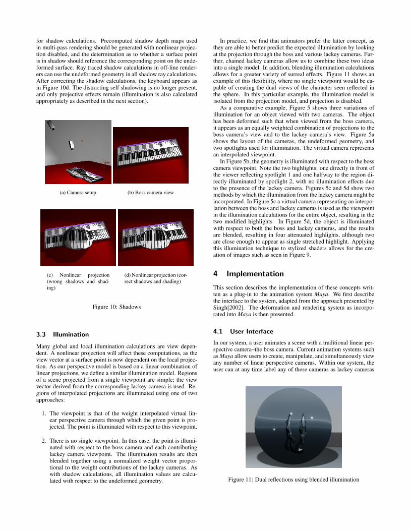
for shadow calculations. Precomputed shadow depth maps usedin multi-pass rendering should be generated with nonlinear projec-tion disabled, and the determination as to whether a surface pointis in shadow should reference the corresponding point on the unde-formed surface. Ray traced shadow calculations in off-line render-ers can use the undeformed geometry in all shadow ray calculations.After correcting the shadow calculations, the keyboard appears asin Figure 10d. The distracting self shadowing is no longer present,and only projective effects remain (illumination is also calculatedappropriately as described in the next section).
(a) Camera setup (b) Boss camera view
(c) Nonlinear projection(wrong shadows and shad-ing)
(d) Nonlinear projection (cor-rect shadows and shading)
Figure 10: Shadows
3.3 Illumination
Many global and local illumination calculations are view depen-dent. A nonlinear projection will affect these computations, as theview vector at a surface point is now dependent on the local projec-tion. As our perspective model is based on a linear combination oflinear projections, we define a similar illumination model. Regionsof a scene projected from a single viewpoint are simple; the viewvector derived from the corresponding lackey camera is used. Re-gions of interpolated projections are illuminated using one of twoapproaches:
1. The viewpoint is that of the weight interpolated virtual lin-ear perspective camera through which the given point is pro-jected. The point is illuminated with respect to this viewpoint.
2. There is no single viewpoint. In this case, the point is illumi-nated with respect to the boss camera and each contributinglackey camera viewpoint. The illumination results are thenblended together using a normalized weight vector propor-tional to the weight contributions of the lackey cameras. Aswith shadow calculations, all illumination values are calcu-lated with respect to the undeformed geometry.
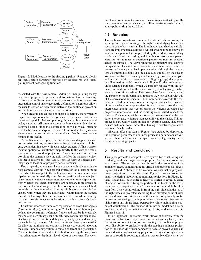
In practice, we find that animators prefer the latter concept, asthey are able to better predict the expected illumination by lookingat the projection through the boss and various lackey cameras. Fur-ther, chained lackey cameras allow us to combine these two ideasinto a single model. In addition, blending illumination calculationsallows for a greater variety of surreal effects. Figure 11 shows anexample of this flexibility, where no single viewpoint would be ca-pable of creating the dual views of the character seen reflected inthe sphere. In this particular example, the illumination model isisolated from the projection model, and projection is disabled.
As a comparative example, Figure 5 shows three variations ofillumination for an object viewed with two cameras. The objecthas been deformed such that when viewed from the boss camera,it appears as an equally weighted combination of projections to theboss camera’s view and to the lackey camera’s view. Figure 5ashows the layout of the cameras, the undeformed geometry, andtwo spotlights used for illumination. The virtual camera representsan interpolated viewpoint.
In Figure 5b, the geometry is illuminated with respect to the bosscamera viewpoint. Note the two highlights: one directly in front ofthe viewer reflecting spotlight 1 and one halfway to the region di-rectly illuminated by spotlight 2, with no illumination effects dueto the presence of the lackey camera. Figures 5c and 5d show twomethods by which the illumination from the lackey camera might beincorporated. In Figure 5c a virtual camera representing an interpo-lation between the boss and lackey cameras is used as the viewpointin the illumination calculations for the entire object, resulting in thetwo modified highlights. In Figure 5d, the object is illuminatedwith respect to both the boss and lackey cameras, and the resultsare blended, resulting in four attenuated highlights, although twoare close enough to appear as single stretched highlight. Applyingthis illumination technique to stylized shaders allows for the cre-ation of images such as seen in Figure 9.
4 Implementation
This section describes the implementation of these concepts writ-ten as a plug-in to the animation system Maya. We first describethe interface to the system, adapted from the approach presented bySingh[2002]. The deformation and rendering system as incorpo-rated into Maya is then presented.
4.1 User Interface
In our system, a user animates a scene with a traditional linear per-spective camera–the boss camera. Current animation systems suchas Maya allow users to create, manipulate, and simultaneously viewany number of linear perspective cameras. Within our system, theuser can at any time label any of these cameras as lackey cameras
Figure 11: Dual reflections using blended illumination
ParameterTransformation
ColorInterpolation
SurfaceParameters
Shader
CameraWeight
ParameterTransformation
SurfaceParameters
Shader
CameraWeight
ParameterTransformation
SurfaceParameters
Shader
CameraWeight
ResultColor
Figure 12: Modifications to the shading pipeline. Rounded blocksrepresent surface parameters provided by the renderer, and rectan-gles represent new shading functions.
associated with the boss camera. Adding or manipulating lackeycameras appropriately updates the deformation of scene geometryto result in a nonlinear projection as seen from the boss camera. Anattenuation control on the geometric deformation magnitude allowsthe user to switch or even blend between the nonlinear projectionand the boss camera’s linear perspective view.
When creating and editing nonlinear projections, users typicallyrequire an exploratory bird’s eye view of the scene that showsthe overall spatial relationship among the scene, boss camera, andlackey cameras. All cameras except the boss camera view the un-deformed scene, since the deformation only has visual meaningfrom the boss camera’s point of view. The individual lackey cameraviews allow the user to visualize the effect of each camera on thenonlinear projection.
To modify relative depths of different views and apply the view-port transformations, the user interactively manipulates a filmboxcube coincident in space with each lackey camera. Affine transfor-mations applied to this filmbox map directly to the viewport trans-formation matrix used for projection. Translating or scaling the filmbox along the camera’s viewing axis modifies the camera’s projec-tion depth relative to other lackey cameras without changing theimage space location of projected scene elements.
Users typically create new lackey cameras coincident with theboss camera with no viewport transformation as a starting pointfrom which to manipulate the lackey cameras. Lackey camera ma-nipulation can dramatically alter the composition of scene objectsin the image. Unless a single nonlinear projection is applied uni-formly across the scene, constraints are necessary to tie objects tolocations in the final image. Therefore, our system creates a defaultconstraint at the center of each group of objects and each lackeycamera with which they are associated. Manipulating the camerathus alters the projection in the boss camera view while ensuringthat the constraint maps to its location in the boss camera’s linearperspective.
Constraint reference frames are represented as cross-hair objects(locators in Maya), visible in Figure 7. Each pair of these objectsdefines the constraint’s reference frames and can be interactivelymanipulated as with any scene object. New constraints can be cre-ated for a group of objects, and they are typically specified uniquelyfor each lackey camera. The constraints are largely responsiblefor allowing nonlinear projections to be easy to control, allowingthe overall image composition to remain coherent and predictable.Constraints also provide a direct method for altering the size, posi-tion, orientation, or depth of a local region of the scene. The view-
port transform does not allow such local changes, as it acts globallyfor a particular camera. As such, we allow constraints to be definedat any point during the workflow.
4.2 Rendering
The nonlinear projection is rendered by interactively deforming thescene geometry and viewing it through the underlying linear per-spective of the boss camera. The illumination and shading calcula-tions are implemented assuming a typical shading pipeline in whichlocal surface parameters are provided by the renderer. An arbitraryshader calculates the shading and illumination from these param-eters and any number of additional parameters that are constantacross the surface. The Maya rendering architecture also supportsinterpolation of user-defined parameters across surfaces, which isnecessary for our particular implementation, although the parame-ters we interpolate could also be calculated directly by the shader.We have constructed two steps in the shading process (analogousto functions within a conventional shading language) that supportour illumination model. As shown in Figure 12, the renderer pro-vides surface parameters, which we partially replace with the sur-face point and normal of the undeformed geometry using a refer-ence to the original surface. This takes place for each camera, andthe parameter modification also replaces the view vector with thatof the corresponding camera. These new values override the ren-derer provided parameters to an arbitrary surface shader, thus pro-viding a surface color appropriate for each camera. Another stepinterpolates among these colors using the weights calculated forprojection interpolation, and the resulting color is used to shade thesurface. The camera weights are stored as parameters that the ren-derer interpolates, which are then accessible to the shader. This ap-proach is particularly useful in that any existing surface shader canbe used with our model, rather than having to construct specializedversions of each shader.
Ghosting effects as seen in Figure 4 are created by duplicatingthe deformed geometry as nonlinear projection parameters are var-ied and then rendering the multiple instances of geometry in thescene with varying opacity.
5 Results and Conclusion
This paper presents a comprehensive system for constructing andrendering nonlinear projections appropriate for use in a productionenvironment. The system has been in use in the production of theanimation Ryan, demonstrating its artistic and practical usefulness.Figures 14 and 15 show stills from animation tests that employ non-linear projections to distort the scene. Figure 1 shows a productionquality rendering incorporating nonlinear projection. In Figure 13,three blocks have been independently projected to reveal featuresotherwise not visible. The upper portion of the block on the left isseen from a viewpoint to the left, the center of the middle block isseen from a viewpoint looking in from the right side, and the top ofthe right block is projected according to an elevated point of viewlooking down. Projections such as this can be exceptionally usefulin creating renderings of complex objects that reveal features notvisible from any single linear perspective, while maintaining a co-herent visualization. The blended illumination model can also beused independently to craft interesting effects, as demonstrated inFigures 9 and 11.
In our approach, animators work almost exclusively with theboss camera for shot composition, but switch among lackey cam-era views to collect ideas for constructing the nonlinear projec-tion. The ability to gradually apply the existing nonlinear projec-tion to the underlying linear perspective has also proven valuable inboth understanding an existing projection during authoring and as ameans of subtly introducing nonlinear perspective effects as a shot

Figure 13: Bringing occluded regions into view with nonlinear per-spective
progresses. We recognize, however, that manipulating many cam-eras can be a complicated task. The development of higher leveltechniques for manipulating multiple cameras is a subject of futurework.
In summary, this paper presents a new formulation for interactivenonlinear projections that addresses spatial scene coherence, shad-ows, and illumination, as well as their integration into current pro-duction pipelines. Practical methods of constructing various non-linear projection effects are shown. Our results showcase the use ofour technique in the commercial animation production Ryan.
6 Acknowledgments
Chris Landreth and the Ryan crew provided the sets and models formany of the images in this paper. Aaron Hertzmann and MichaelMcGuffin provided feedback on an early draft. Alias provided theMaya animation software for both research and production.
References
AGRAWALA, M., ZORIN, D., AND MUNZNER, T. 2000. Artistic multipro-jection rendering. In Proceedings of Eurographics Rendering Workshop2000, Eurographics, 125–136.
ALEXA, M. 2002. Linear combination of transformations. In Proceed-ings of the 29th annual conference on Computer graphics and interactivetechniques, ACM Press, ACM, 380–387.
BARR, A. H. 1986. Ray tracing deformed surfaces. In Proceedings ofthe 13th annual conference on Computer graphics and interactive tech-niques, ACM Press, ACM, 287–296.
DORSEY, J. O., SILLION, F. X., AND GREENBERG, D. P. 1991. Designand simulation of opera lighting and projection effects. In Proceedings ofthe 18th annual conference on Computer graphics and interactive tech-niques, ACM Press, ACM, 41–50.
FOLEY, J., VAN DAM, A., FEINER, S., AND HUGHES, J. 1993. ComputerGraphics: Principles and Practice. Addison Wesley.
FU, C.-W., WONG, T.-T., AND HENG, P.-A. 1999. Computing visibilityfor triangulated panoramas. In Proceedings of Eurographics RenderingWorkshop 1999, Eurographics, 169–182.
GLASSNER, A., 2000. Cubism and cameras: Free-form optics for computergraphics. Microsoft Research Technical Report MSR-TR-2000-05, Jan-uary.
LEVENE, J. 1998. A Framework for Non-Realistic Projections. Master’sthesis, Massachusetts Institute of Technology.
MARTIN, D., GARCIA, S., AND TORRES, J. C. 2000. Observer depen-dent deformations in illustration. In Proceedings of the first internationalsymposium on Non-photorealistic animation and rendering, ACM Press,ACM, 75–82.
MAX, N. L. 1983. Computer graphics distortion for imax and omnimaxprojection. In Nicograph ’83 Proceedings, Nicograph Association, 137–159.
PELEG, S., ROUSSO, B., RAV-ACHA, A., AND ZOMET, A. 2000. Mo-saicing on adaptive manifolds. IEEE Transactions on Pattern Analysisand Machine Learning 22, 10, 1144–1154.
RADEMACHER, P., AND BISHOP, G. 1998. Multiple-center-of-projectionimages. In Proceedings of the 25th annual conference on Computergraphics and interactive techniques, ACM Press, ACM, 199–206.
RADEMACHER, P. 1999. View-dependent geometry. In Proceedings ofthe 26th annual conference on Computer graphics and interactive tech-niques, ACM Press/Addison-Wesley Publishing Co., ACM, 439–446.
SEITZ, S. M., AND DYER, C. R. 1996. View morphing. In Proceedings ofthe 23rd annual conference on Computer graphics and interactive tech-niques, ACM Press, ACM, 21–30.
SINGH, K. 2002. A fresh perspective. In Proceedings of Graphics Interface2002, 17–24.
WOOD, D. N., FINKELSTEIN, A., HUGHES, J. F., THAYER, C. E., ANDSALESIN, D. H. 1997. Multiperspective panoramas for cel animation. InProceedings of the 24th annual conference on Computer graphics and in-teractive techniques, ACM Press/Addison-Wesley Publishing Co., ACM,243–250.
WYVILL, G., AND MCNAUGHTON, C. 1990. Optical models. In Proceed-ings of CGI 1990.
ZORIN, D., AND BARR, A. H. 1995. Correction of geometric perceptualdistortions in pictures. In Proceedings of the 22nd annual conferenceon Computer graphics and interactive techniques, ACM Press, ACM,257–264.

(a) (b) (c) (d)
Figure 14: Ryan Cafeteria Set
(a) (b) (c) (d)
(e) (f) (g) (h)
Figure 15: Ryan Bathroom Set