s-bus - driver of s-bus protocol for saia-burgess...
TRANSCRIPT
asix4 User’s Manual
see and get more…
S-BUS - Driver of S-BUS Protocol for SAIA-Burgess Electronics PLCs
User’s Manual
Doc. No. ENP4051
Version: 29-08-2005
User’s Manual asix4
ASKOM® and asix ® are registered trademarks of ASKOM Spółka z o.o., Gliwice. Other brand names, trademarks, and registered trademarks are the property of their respective holders. All rights reserved including the right of reproduction in whole or in part in any form. No part of this publication may be reproduced or transmitted in any form or by any means, electronic or mechanical, including photocopying, recording, or by any information storage and retrieval system, without prior written permission from the ASKOM. ASKOM sp. z o. o. shall not be liable for any damages arising out of the use of information included in the publication content. Copyright © 2005, ASKOM Sp. z o. o., Gliwice
ASKOM Sp. z o. o., ul. Józefa Sowińskiego 13, 44-121 Gliwice, tel. +48 (0) 32 3018100, fax +48 (0) 32 3018101, http://www.askom.com.pl, e-mail: [email protected]

asix4 S-BUS - Driver of S-BUS Protocol for SAIA-Burgess…
©ASKOM, Gliwice August 2005 3
1. S-BUS - Driver of S-BUS Protocol for SAIA-Burgess Electronics PLCs
1.1. Driver Use The S-BUS driver is used for data exchange between PCD PLCs of SAIA-Burgess Electronics and an asix system computer. The S-BUS protocol is compatible to the specification "SAIA S-Bus for the PCD family", Edition 26/739 E2-05.96, developed by SAIA-Burgess Electronics. For purposes of communication with the asix system, the following interfaces of PCD PLCs may be used:
- the PGU interface (RS-232C); - additional communication interfaces, the number and type of which depend on the
controller type and configuration. These interfaces enable data transmission in one of the standards given below:
RS-232C, RS-422, RS-485, current loop of 20 mA.
NOTE For data exchange you should use a cable made according to the specification PCD8.K111.See: Figure 1. Cable Compatible with the PCD8.K111 Specification..
Figure 1. Cable Compatible with the PCD8.K111 Specification.
1.2. Declaration of Transmission Channel The full syntax of declaration of transmission channel using the S-BUS protocol is given below:
logical_channel_name=S-BUS, id, port [, baud]
where: S-BUS - driver name;

S-BUS - Driver of S-BUS Protocol for SAIA-Burgess… asix4
4 August 2005 ©ASKOM, Gliwice
id - number of the controller in the S-BUS network; port - port name: COM1, COM2 etc.;
optional parameters: baud - transmission channel.
If the optional parameters are not given, then by default it is assumed as follows: transmission speed of 9600 baud. EXAMPLE
The declaration of the logical channel named CHAN1 operating according to the S-BUS protocol and exchanging data with the controller numbered 1 through the COM2 port with a speed of 9600 baud is as follows:
CHAN1 = S-BUS, 1, COM2 The S-BUS driver is loaded as a DLL automatically.
1.3. Addressing the Process Variables
The syntax of symbolic address which is used for variables belonging to the S-BUS driver channel is as follows:
<type><index>
where: type - variable type, index - index within the type.
Symbols of variable types (the type of raw variable value is given in parentheses): C - values of counters (DWORD), F - states of flags (WORD), I - values of inputs (WORD), K - current date and time in the form of an 8-bit array (BYTE), O - values of outputs (WORD), RI - values of registers treated as 32-bit fixed-point signed numbers
(LONG), RF - values of registers treated as 32-bit floating-point numbers in
SAIA format (FLOAT), S - status (WORD), T - values of timers (DWORD).
Values of variables of C, F, O, RI, RF, T that may be read and written. Values of variables of I, S type that may be only read. Values of variables of K types are used by the driver for time synchronization with a PCD. The structure of K type variable buffer is as follows:
byte 0 - number of a week in a year, byte 1 - number of a week day (Monday - 1, Sunday - 7), byte 2 - two least significant digits of a year, byte 3 - month, byte 4 - day, byte 5 - hour,
asix4 S-BUS - Driver of S-BUS Protocol for SAIA-Burgess…
©ASKOM, Gliwice August 2005 5
byte 6 - minute, byte 7 - second.
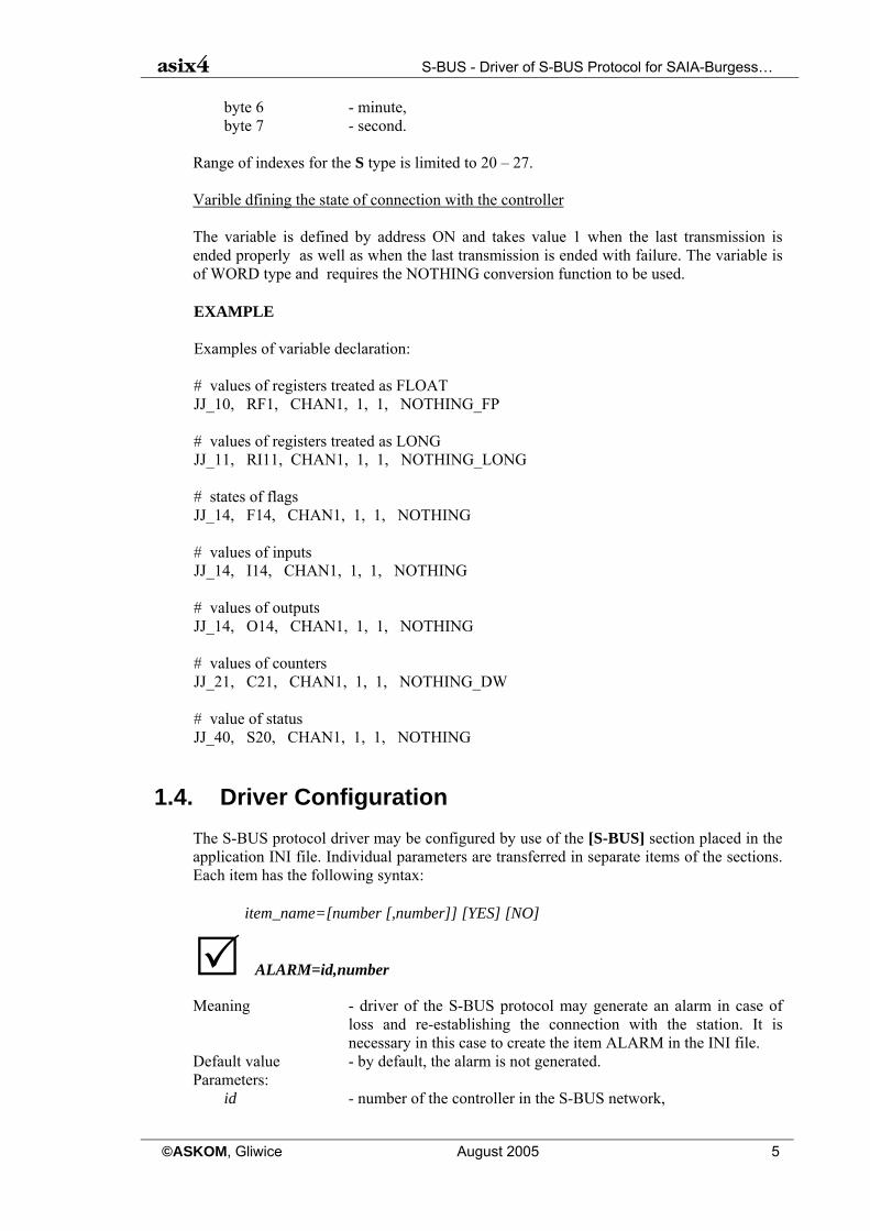
Range of indexes for the S type is limited to 20 – 27. Varible dfining the state of connection with the controller The variable is defined by address ON and takes value 1 when the last transmission is ended properly as well as when the last transmission is ended with failure. The variable is of WORD type and requires the NOTHING conversion function to be used. EXAMPLE Examples of variable declaration: # values of registers treated as FLOAT JJ_10, RF1, CHAN1, 1, 1, NOTHING_FP # values of registers treated as LONG JJ_11, RI11, CHAN1, 1, 1, NOTHING_LONG # states of flags JJ_14, F14, CHAN1, 1, 1, NOTHING # values of inputs JJ_14, I14, CHAN1, 1, 1, NOTHING # values of outputs JJ_14, O14, CHAN1, 1, 1, NOTHING # values of counters JJ_21, C21, CHAN1, 1, 1, NOTHING_DW # value of status JJ_40, S20, CHAN1, 1, 1, NOTHING
1.4. Driver Configuration
The S-BUS protocol driver may be configured by use of the [S-BUS] section placed in the application INI file. Individual parameters are transferred in separate items of the sections. Each item has the following syntax:
item_name=[number [,number]] [YES] [NO]
ALARM=id,number
Meaning - driver of the S-BUS protocol may generate an alarm in case of loss and re-establishing the connection with the station. It is necessary in this case to create the item ALARM in the INI file.
Default value - by default, the alarm is not generated. Parameters:
id - number of the controller in the S-BUS network,
S-BUS - Driver of S-BUS Protocol for SAIA-Burgess… asix4
6 August 2005 ©ASKOM, Gliwice
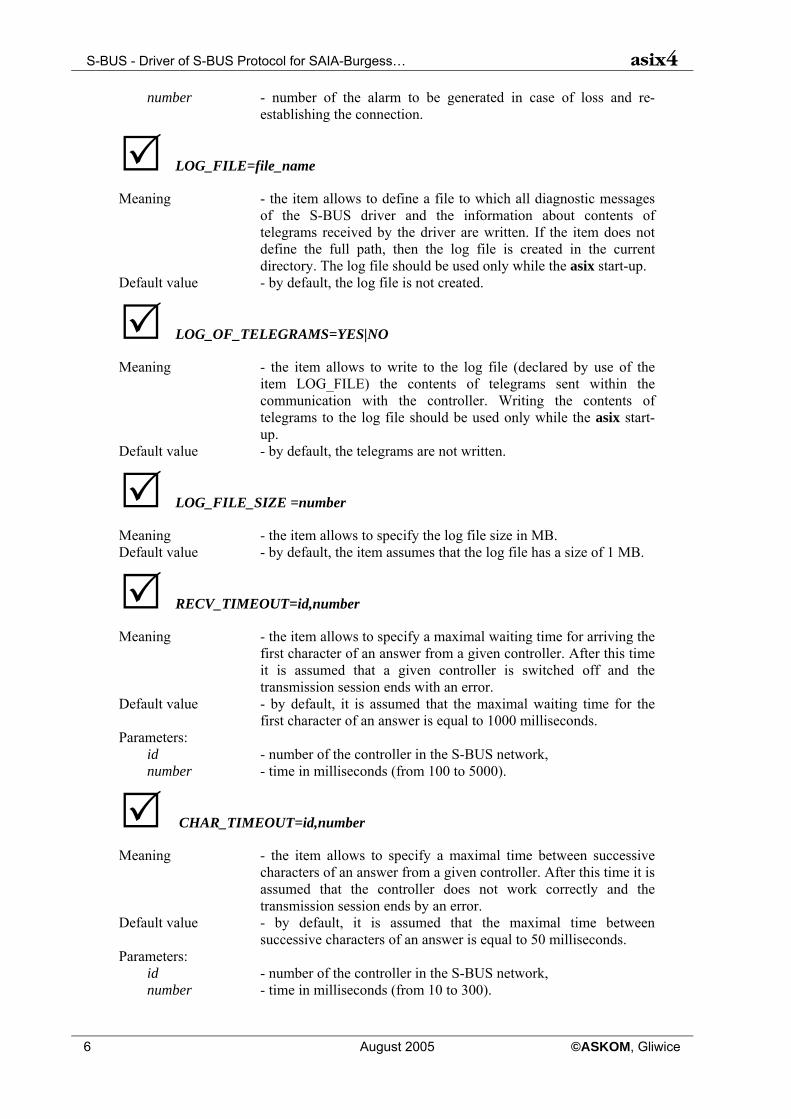
number - number of the alarm to be generated in case of loss and re-establishing the connection.
LOG_FILE=file_name
Meaning - the item allows to define a file to which all diagnostic messages of the S-BUS driver and the information about contents of telegrams received by the driver are written. If the item does not define the full path, then the log file is created in the current directory. The log file should be used only while the asix start-up.
Default value - by default, the log file is not created.
LOG_OF_TELEGRAMS=YES|NO
Meaning - the item allows to write to the log file (declared by use of the item LOG_FILE) the contents of telegrams sent within the communication with the controller. Writing the contents of telegrams to the log file should be used only while the asix start-up.
Default value - by default, the telegrams are not written.
LOG_FILE_SIZE =number
Meaning - the item allows to specify the log file size in MB. Default value - by default, the item assumes that the log file has a size of 1 MB.
RECV_TIMEOUT=id,number
Meaning - the item allows to specify a maximal waiting time for arriving the first character of an answer from a given controller. After this time it is assumed that a given controller is switched off and the transmission session ends with an error.
Default value - by default, it is assumed that the maximal waiting time for the first character of an answer is equal to 1000 milliseconds.
Parameters: id - number of the controller in the S-BUS network, number - time in milliseconds (from 100 to 5000).
CHAR_TIMEOUT=id,number
Meaning - the item allows to specify a maximal time between successive characters of an answer from a given controller. After this time it is assumed that the controller does not work correctly and the transmission session ends by an error.
Default value - by default, it is assumed that the maximal time between successive characters of an answer is equal to 50 milliseconds.
Parameters: id - number of the controller in the S-BUS network, number - time in milliseconds (from 10 to 300).

asix4 S-BUS - Driver of S-BUS Protocol for SAIA-Burgess…
©ASKOM, Gliwice August 2005 7
ADDRESS_TIMEOUT=number
Meaning - the item allows to determine a time period between the character of address and the first character of data in an order sent to the PCD. The time period is necessary to switch over the PGU interface from the mode of address receiving to the mode of data receiving.
Default value - by default, it is assumed that the time period between the address character and the first character of data is equal to 25 milliseconds.
Parameters: number - time in milliseconds.
NUMBER_OF_REPETITIONS=number
Meaning - the item allows to specify a number of repetitions in case of a transmission error.
Default value - by default, the item assumes a values of 0 (no repetitions).
Time Synchronization Between the asix System and SAIA Controllers
In the S-BUS driver there is a mechanism of time synchronization between the asix system and SAIA controllers. The time synchronization is activated for each channel separately by means of items placed in the ASMEN section.
TIME_SYNCHRONIZATION = channel, variable
Parameters: channel - name of a transmission channel used for communication with a
given SAIA PLC; variable - name of an ASMEN variable belonging to the channel
CHANNEL and used for time synchronization.
The time synchronization consists on cyclic writing to the controller a frame containing an actual asix time. The frame is written by means of a built-in function for writing the S_BUS protocol time according to a frequency assigned to variable. The variable type must be the K type (clock support), the number of elements assigned to variable must accomodate the time frame, i.e. it must have a size of min. 8 bytes. As a conversion function the NOTHING_BYTE function must be used.
EXAMPLE The definition of every-minute time synchronization for the channel CHAN1 by means of the variable SYNCHRO1: [ASMEN] DATA= SBUS.DAT CHAN1 = S-BUS,0,COM1,9600 TIME_SYNCHRONIZATION = CHAN1, SYNCHRO1 The declaration of the variable SYNCHRO1 is found in the file SBUS.DAT and has the following form:

S-BUS - Driver of S-BUS Protocol for SAIA-Burgess… asix4
8 August 2005 ©ASKOM, Gliwice
SYNCHRO1, clock synchronization, K, CHAN1, 8, 60, NOTHING_BYTE
MODE=id,mode_name
Meaning - up to now, the S-BUS protocol driver has serviced the PARITY transmission mode; from the version 1.02.000 the driver services also BREAK and DATA modes; settings of a proper mode are realized by the MODE parameter.
Default value - omission of the item causes the PARITY mode realization. Parameters:
id - numer of controllers in the S-BUS network, mode_name - one of the following words: PARITY, BREAK lub DATA.
NOTICE Using a specific mode, one should remember about proper controller parametrization - the controller should use the same mode.
1.5. Connection by Means of Modem
Driver of the S-BUS protocol is also able to exchange the data by means of a modem, also with use of the PGU interface. Connection by means of a modem is possible only by using the DATA transmission mode. S-BUS driver channel is the client of the AsComm server named S:BUS:n where:
n - it is the number of the serial port received from the ASMEN channel definition, e.g. if channel_name=S=BUS,1,com2,… then a client name is S-BUS:2.
To establish a connection on dial-up links by means of the AsComm program, the record given below must be placed in the [MODBUS:n] section:
Switched_line = Yes If the modem is connected to the other port than COMn, then you should give the number of this port by means of the parameter Port or specify the modem name by means of the parameter Modem. You should also give a telephone number and define other required parameters. If MODBUS driver has to communicate with many controllers by means of the same modem, then one should define suitable number of channels taking the parameter port as a virtual transmission channel and place suitable number of sections in the INI file, by specifying in them an appropriate telephone number. EXAMPLE An example of the initialization file content: [ASMEN]

asix4 S-BUS - Driver of S-BUS Protocol for SAIA-Burgess…
©ASKOM, Gliwice August 2005 9
.... Chan1 = MODBUS,1,COM11,9600,8,none,1,16,16 Chan2 = MODBUS,1,COM12,9600,8,none,1,16,16 [MODBUS:11] Switched_line = Yes Modem = US Robotics Number = 11111111 [MODBUS:12] Switched_line = Yes Modem = US Robotics Number = 22222222 In the example above Chan1 will communicate with a controller placed under the telephone number 11111111, and the Chan2 with a controller placed under the telephone number 22222222. The US Robotics modem will be used. The Modem parameter may be replaced by the parameter Port, which specifies the number of the serial port to which the modem is connected. You should notice that the description of application of the MODBUS driver on switched links does not include any modem configuration guidelines. The modem configuration depends on modem types.

S-BUS - Driver of S-BUS Protocol for SAIA-Burgess… asix4
10 August 2005 ©ASKOM, Gliwice

asix4 List of Figures
©ASKOM, Gliwice August 2005 11
2. List of Figures Figure 1. Cable Compatible with the PCD8.K111 Specification....................................................................... 3

List of Figures asix4
12 August 2005 ©ASKOM, Gliwice

asix4 Table of Contents
©ASKOM, Gliwice August 2005 13
1. S-BUS - DRIVER OF S-BUS PROTOCOL FOR SAIA-BURGESS ELECTRONICS PLCS 3 1.1. DRIVER USE 3 1.2. DECLARATION OF TRANSMISSION CHANNEL 3 1.3. ADDRESSING THE PROCESS VARIABLES 4 1.4. DRIVER CONFIGURATION 5 1.5. CONNECTION BY MEANS OF MODEM 8
2. LIST OF FIGURES 11