s. gardiner , g. c. clifton and g a macrae innovations... · eighty percent of crack widths were...
TRANSCRIPT

19 Gardiner Page 1
Steel Innovations Conference 2013 Christchurch, New Zealand
21-22 February 2013
PERFORMANCE, DAMAGE ASSESSMENT AND REPAIR OF A MULTISTOREY ECCENTRICALLY BRACED FRAMED BUILDING FOLLOWING THE CHRISTCHURCH EARTHQUAKE SERIES
S. Gardiner1, G. C. Clifton2 and G A MacRae3
ABSTRACT This paper presents a summary of the performance, damage assessment and repair of a multi-storey Eccentrically Braced Frame (EBF) building following the Christchurch earthquake series of 2010/2011. It describes the damage observed and the methods used in the post-earthquake evaluation of the building. It includes a description and the results of non-destructive processes used for the determination of active link plastic demand and the subsequent recommendations for leaving links in place or replacement. It presents probable reasons as to why one of the active links fractured and provides some recommendations for future EBF detailing, both to increase toughness and for ease of replacement. The paper also covers practical considerations relating to the repair and replacement of damaged active links in existing EBF systems in which replacement requires cutting out and fitting of new links. The paper is an update to one of the same title presented at the SESOC Conference in November 2012.
Keywords: Steel, eccentrically braced frame, earthquake, repair.
Introduction The 22 storey steel framed Pacific Tower building located in Gloucester Street, Christchurch was completed in 2009. The building accommodates the Rendezvous Hotel Christchurch (formerly The Marque Christchurch) with the hotel reception and restaurant at ground floor level, four storeys that house the car-stackers, with hotel rooms above and residential apartments for the upper seven levels. On 4 September 2010 the building experienced the M7.1 Darfield earthquake with largely cosmetic damage observed. The subsequent earthquake series, including the most intense M6.3 Lyttelton earthquake of 22 February 2011, and significant earthquakes of 13 June 2011 and 23 December 2011, resulted in a range of structural and non-structural damage, including fracture of an active link. The 22 February earthquake was the most intense to impact eccentrically braced framed systems recorded to date worldwide. While damage was observed to a number of structural and non-structural elements, including concrete block masonry walls and the exterior precast concrete cladding panels and fixings, this paper focusses principally on the performance of the steel frames and floor slabs.
1 Sean Gardiner, Spiire, Christchurch. Email: [email protected] 2 G. Charles Clifton, University of Auckland. Email: [email protected] 3 Gregory A MacRae, University of Canterbury. Email: Gregory.macrae@canterbury .ac.nz

19 Gardiner Page 2
Building Structure
The building structure is steel framed, with typically 150mm thick Comflor 80 floors spanning 4 meters, reinforced with HD10 bars at 300mm centres each way and supplementary drag tie steel bars, supported on composite steel beams. The building is supported laterally by a combination of K-braced and D-braced Eccentrically Braced Frames (EBF). In addition there are Moment Resisting Frames (MRF) at the uppermost two levels, and “super” MRFs replacing steel braces (matched stiffness) on the exterior wall lines at the ground floor level. Transfer diaphragms are located at the level 6 and level 11 building setbacks, transferring loads to steel frames on the perimeter of the building at those locations. The steel sections throughout are typically hot rolled Universal Beams (UB) and Universal Columns (UC), with fabricated Steltech sections (High Capacity Columns (HCC)) at the lower levels of the building and forming the active links resisting the highest shear demand. The building is founded on large reinforced concrete foundation beams and a mixture of 1500 diameter concrete caisson and 900 diameter helix steel screw piles, typically 12 metres in length.
Earthquake Performance
Original Design
The building was designed in 2007 using AS/NZS1170.5:2004 [1] (utilising a hazard factor, Z = 0.22 for Christchurch and design structural ductility factor, µ = 3) and NZS3404:1997 [2], prior to the incorporation of Amendment 2. The actual ductility of the original design was lower at µact ≈ 1.5, due to stiffness requirements, conservative sizing of the D-braced active links, standardisation of link sizes across a number of levels to aid fabrication and minimum base shear requirements. This is typical of a building of this size and complexity. The design fundamental period of the building was almost 4 seconds in the north-south direction and just over 3 seconds in the east-west direction, the former leading to minimum requirements governing the design base shear coefficient in that direction. The building was designed using a capacity design approach, with maximum design actions on secondary elements limited to those corresponding to elastic levels of load in accordance with cl. 12.3.3.4 of NZS 3404, and incorporated concurrent actions (100% + 30%) for elements in two-way frames in accordance with AS/NZS 1170 and NZS 3404. Post-Earthquake Evaluations
Visual Inspections
Inspections were carried out after the main September 2010 and February 2011 earthquakes, as well as the Boxing Day, June and December aftershocks. The main structural frame elements of the building are concealed behind (fire-rated) gypsum board linings, except at the level 2 carstacker deck. The building investigations have therefore taken a staged approach, whereby initially a sample of key areas were inspected and, upon considering the damage revealed, further inspections are undertaken if deemed warranted. Initial inspections of a sample of active links after the September 2010 and February 2012 earthquakes, revealed minor permanent offsets in those regions and the onset of shear yielding as evidenced by the appearance of diagonal Luders lines, as shown in Figure 1, and paint flaking in the web regions. Initial conclusions were the links had been subjected to a few cycles of demand in the inelastic range, but that the steel would likely have retained sufficient ability to absorb damage to withstand, at least, another Ultimate Limit State (ULS) earthquake.

19 Gardiner Page 3
Figure 1: Active link with diagonal Luders lines. Image Spiire New Zealand Ltd.
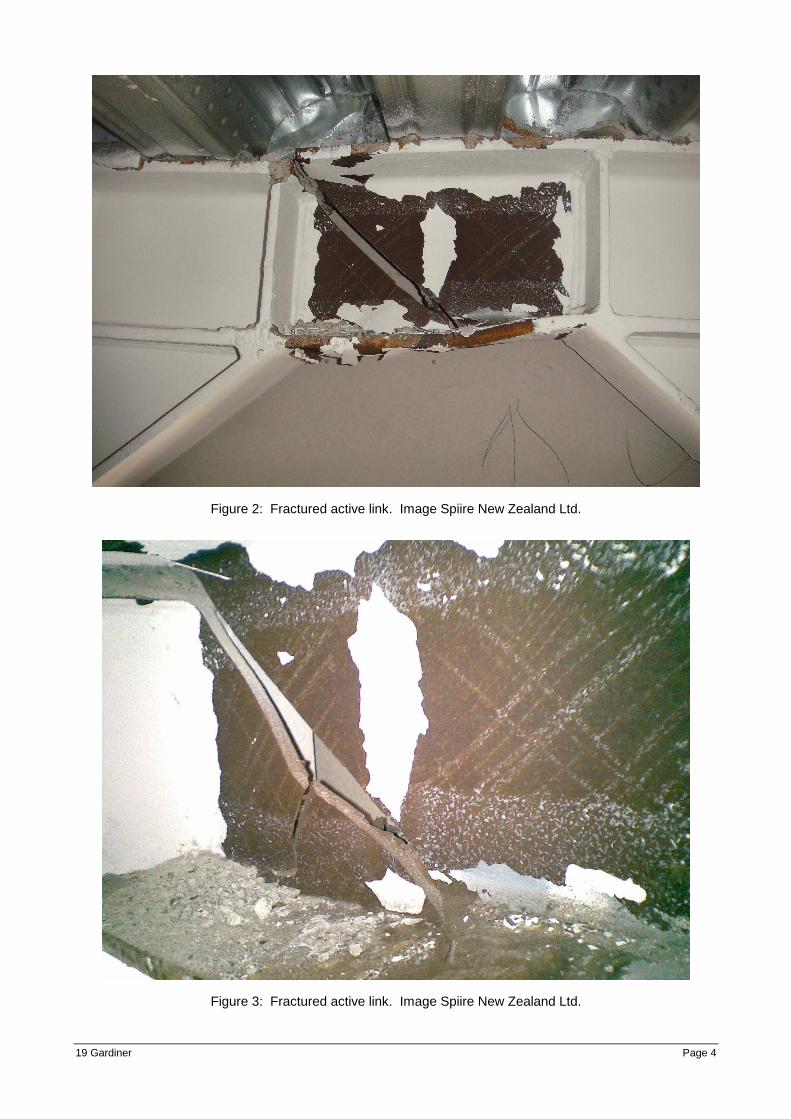
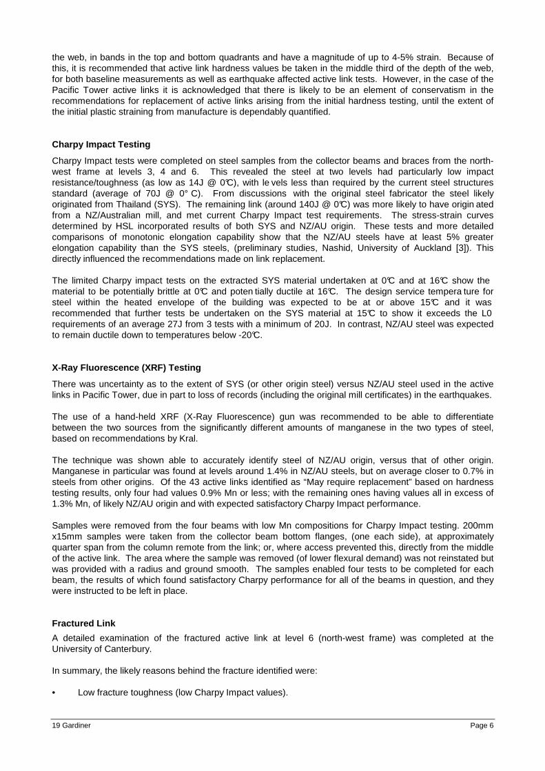
Building permanent offsets were able to be measured using plumb lines and measurements to the lift guide rails in the lift shafts, as well as external surveys. These revealed maximum building offsets of 60-80mm approximately halfway up the height of the tower, consistent with second mode response, and an average inter-storey drift profile less than 0.3%, after the February 2012 earthquake. Subsequent shaking has tended to straighten the building closer to vertical, due to “dynamic self-centering” as a result of the column and concrete deck elements remaining elastic and tending to return the building to vertical. In August 2011, 5 months after the most significant shaking event, during inspections of the carstacker restraints, a fractured link was discovered at the north-western corner of the building at the underside of Level 6 (top of the western podium and carstacker levels) as shown in Figures 2 and 3. It is suspected the fracture occurred as a result of the June 2011 earthquake, given the evidence of several cycles of inelastic demand, and the cooler temperatures during that event, however it could have occurred in the February earthquake during load reversal. This lead to the detailed inspections of all 126 active links, but revealed no further fractures. As a result of this, it is recommended all active links of EBF buildings be inspected following earthquakes where any inelastic demand is evident. Inspection hatches should ideally be placed to allow quick and clean visual inspection, and access for further testing if necessary.
19 Gardiner Page 4
Figure 2: Fractured active link. Image Spiire New Zealand Ltd.
Figure 3: Fractured active link. Image Spiire New Zealand Ltd.

19 Gardiner Page 5
Note that Figures 1 to 3 all indicate a lack of seismic induced plastic strain penetration into the top and bottom 20% of the web. Preliminary indications are that this may be due to prestraining of these regions of hot rolled sections by the manufacturing process. No damage or sign of any permanent displacement was observed to steel MRFs, columns, braces or welded or bolted connections. Floor coverings were lifted at each level to reveal cracks of varying widths, extents and locations. A number of cracks, particularly those above supporting beams, were likely to have been in place prior to the earthquakes, but may well have been made worse as a result of the horizontal and vertical ground shaking effects. Eighty percent of crack widths were less than 0.5mm, but a number were up to 1mm wide and up to 1.5mm wide in a few localised areas. The earthquake induced cracking indicated a torsional response to the building, with cracking near the corners, possibly caused by different seismic resisting systems becoming inelastic at different times as well as by any torsional motion from the earthquake. Cracking in the north-south may reflect the weaker floor in this direction given that the decking principally spans that way and the alternating floor slab thickness due to the parallel decking ribs. Some localised effects were noted around perimeter columns that may reflect tension in the floor tying the columns back into the slab. As expected there was a higher incidence of cracking in the slab directly above active links, however not to the extent considered likely if the links had plasticially deformed to their code prescribed limits. No potential overall diaphragm failure planes were observed from floor slab crack mapping. Magnetic Particle Inspections
Active links with permanent offsets greater than around 1.5% rotation from horizontal were subject to Magnetic Particle (MP) inspection. In consultation with the New Zealand Welding Centre, most “crack-like indications” were able to be removed with localised burr grinding to 2mm and feathering out. Those that were not had the weld replaced. It is the opinion of those parties involved with the inspection and repairs that due to their locations, the indications were not likely as a result of the earthquake, but were in place after initial fabrication and did not affect the performance of the frames. Similar significant cracks in welds were observed in beam to column specimens manufactured and tested from 2000 to 2004 in research undertaken by HERA, which showed that localised cracking in a beam to column weld designed to the capacity design procedure of NZS 3404 did not automatically lead to final weld failure. Hardness Testing
Hardness testing was undertaken on the fractured link and the three remaining active links on the north-western frame, inside and outside of the active link region. Given the relative increases in hardness observed it was considered further testing would likely require the replacement of all the links in that frame. Measurements were taken in Leeb Hardness with an Impact Device D and output in HLD units, due to its compact nature and ability to test on site. Holmes Solutions Ltd (HSL) was engaged to undertake hardness testing of all the active links in the building to try to quantify the extent of strain hardening, and based on the maximum strain capacity of the steel, the corresponding reduction in strain capacity of the active links as a result of inelastic demand in the earthquakes. Material from the links removed from the north-western frame was used to produce stress-strain and stress-hardness correlation curves. This, in conjunction with the hardness testing of the remaining links in the building, allowed estimates to be made of the induced strain in the links and corresponding reduction in strain capacity. The process of taking undertaking hardness tests in-situ requires the impact surface to be cleaned to a bright and smooth finish, with a number of sites tested across each link. Each site also has 5-6 individual tests approximately 5mm apart to try to minimise the influence of localised surface influences. Test sites should be clear of weld Heat Affected Zones (HAZ) and the stiffening effects of the flanges and stiffeners. In addition, recent and on-going hardness mapping of webs of hot-rolled sections at the University of Auckland has revealed a high level of manufacturing induced plastic strain and corresponding hardness in the web upper and lower quarters of parent, hot-rolled material. These plastic strains are greatest in the surface of
19 Gardiner Page 6
the web, in bands in the top and bottom quadrants and have a magnitude of up to 4-5% strain. Because of this, it is recommended that active link hardness values be taken in the middle third of the depth of the web, for both baseline measurements as well as earthquake affected active link tests. However, in the case of the Pacific Tower active links it is acknowledged that there is likely to be an element of conservatism in the recommendations for replacement of active links arising from the initial hardness testing, until the extent of the initial plastic straining from manufacture is dependably quantified. Charpy Impact Testing
Charpy Impact tests were completed on steel samples from the collector beams and braces from the north-west frame at levels 3, 4 and 6. This revealed the steel at two levels had particularly low impact resistance/toughness (as low as 14J @ 0°C), with le vels less than required by the current steel structures standard (average of 70J @ 0° C). From discussions with the original steel fabricator the steel likely originated from Thailand (SYS). The remaining link (around 140J @ 0°C) was more likely to have origin ated from a NZ/Australian mill, and met current Charpy Impact test requirements. The stress-strain curves determined by HSL incorporated results of both SYS and NZ/AU origin. These tests and more detailed comparisons of monotonic elongation capability show that the NZ/AU steels have at least 5% greater elongation capability than the SYS steels, (preliminary studies, Nashid, University of Auckland [3]). This directly influenced the recommendations made on link replacement. The limited Charpy impact tests on the extracted SYS material undertaken at 0°C and at 16°C show the material to be potentially brittle at 0°C and poten tially ductile at 16°C. The design service tempera ture for steel within the heated envelope of the building was expected to be at or above 15°C and it was recommended that further tests be undertaken on the SYS material at 15°C to show it exceeds the L0 requirements of an average 27J from 3 tests with a minimum of 20J. In contrast, NZ/AU steel was expected to remain ductile down to temperatures below -20°C. X-Ray Fluorescence (XRF) Testing
There was uncertainty as to the extent of SYS (or other origin steel) versus NZ/AU steel used in the active links in Pacific Tower, due in part to loss of records (including the original mill certificates) in the earthquakes. The use of a hand-held XRF (X-Ray Fluorescence) gun was recommended to be able to differentiate between the two sources from the significantly different amounts of manganese in the two types of steel, based on recommendations by Kral. The technique was shown able to accurately identify steel of NZ/AU origin, versus that of other origin. Manganese in particular was found at levels around 1.4% in NZ/AU steels, but on average closer to 0.7% in steels from other origins. Of the 43 active links identified as “May require replacement” based on hardness testing results, only four had values 0.9% Mn or less; with the remaining ones having values all in excess of 1.3% Mn, of likely NZ/AU origin and with expected satisfactory Charpy Impact performance. Samples were removed from the four beams with low Mn compositions for Charpy Impact testing. 200mm x15mm samples were taken from the collector beam bottom flanges, (one each side), at approximately quarter span from the column remote from the link; or, where access prevented this, directly from the middle of the active link. The area where the sample was removed (of lower flexural demand) was not reinstated but was provided with a radius and ground smooth. The samples enabled four tests to be completed for each beam, the results of which found satisfactory Charpy performance for all of the beams in question, and they were instructed to be left in place. Fractured Link
A detailed examination of the fractured active link at level 6 (north-west frame) was completed at the University of Canterbury. In summary, the likely reasons behind the fracture identified were: • Low fracture toughness (low Charpy Impact values).

19 Gardiner Page 7
• The location of a shear stud(s) above the brace web stiffeners forming the active link was a potential fracture initiation site.
• Shorter link length imposing higher hinge rotations in this frame compared to the others in the building. • The colder temperatures associated with the likely time of the fracture, in the two strong earthquakes
of 13 June 2011, with much colder air temperatures compared with the first damaging earthquake event of 22 February 2011.
Figure 4: Link fracture adjacent to shear stud. Image courtesy Milo Kral, University of Canterbury
Interim recommendations are that checks be put in place to ensure that only steels complying with the current provisions of NZS3404 [2], for example Grade S0, are used in the fabrication of EBFs. Shear studs located above or near active link regions should be located no closer than above half way across the panel zone adjacent to the active link and we recommend it be located above the panel zone stiffener on the panel zone side remote from the active link. It is also recommended links of similar length be used for frames acting in the same direction, so that imposed plastic rotation demands are similar. Post-Earthquake Strength
Building performance
The building experienced earthquakes greater than the design level earthquake associated with the revised Christchurch value of Z = 0.3. Given the satisfactory performance of the building (by real earthquake testing and a combined period of intense shaking in excess of 20 seconds) it was considered to have met the revised Code requirements (once the structural repairs were complete). The performance of the building in the earthquake series provides some key information that can be validly

19 Gardiner Page 8
used in any assessment. This is covered under NZS 3404 [2] Section 17.4 Proof Testing which is what the earthquakes have done. Key findings from this are that: • The design procedures, including capacity design considerations, were sufficiently robust to
concentrate inelastic demand into the active links even with an observed increased strength and stiffness.
• Heavy bolted connections performed very well and to expectation. • The structural system coped with the loss of one active link without noticeable distress beyond that
immediate location (referring to the fractured link at level 6 in the north-west corner). • The structure was loaded to approximately twice the previous design level which is still some 1.7 times
the current new design level without unexpected performance with the exception of the one link fracture in these events. Based on this, it is likely that the whole building performance meets 100% of the new Code level requirements.
Active Link Residual Strain Capacity
An assessment of the residual ductility/strain capacity of the active links was required to confirm satisfactory future seismic performance. The strains due to an earthquake are cyclic in nature, however, the comparisons leading to potential lost strain capacity as given in Table 1 below are based on monotonic evaluations, because the data necessary for cyclic evaluation of shear strain in active links is not currently available. University of Auckland research into damage accumulation due to cyclic plasticity in steel [4] has shown that using monotonic evaluation is increasingly conservative for plastic strains below 10%. It should be noted the variation in individual hardness values at a given site leads to the range of potential lost strain capacity reported. Variation in individual hardness is also due to variation in plastic demand across the active link web. It is expected the strain hardening characteristics of steel will even these out with repeated cyclic demand, avoiding excessive strain build-up in any particular location. Based on the findings of the HSL report and those from examinations at the universities, the results in Table 1 have been found.
Table 1: Hardness to strain correlations.
Hardness (HLD) Approximate Strain Potential Lost Strain Capacity
<4001 <2% <10%
400 - 410 5% 10% - 20%
410 - 420 7% 20% - 30%
420 - 440 10% 30% - 50%
> 440 >20% > 50%
1. Links with a Leeb hardness (HLD) < 400 are essentially unstrained and are within the likely natural
variation of the parent material. As noted above, these findings are increasingly conservative for plastic strains below 10%. This is because the reserve capacity after monotonic loading and that after cyclic earthquake-type loading has not been quantified. Seal [5] (University of Auckland) shows that for plastic strains of less than around 10% the cyclic impact is considerably less than the monotonic impact. That is, the damage from 2 or more cycles of plastic strain are not cumulative, and up to around 5% plastic strain after the first 2 cycles there is little increase in damage for many more cycles. This means an assessment based on monotonic strain reserve capacity is conservative when applied to earthquake damage. From a damage point of view, any SYS steel that had been strained at all (HLD>400), was recommended to be replaced. This is because the already low Charpy Impact performance would be reduced further by any inelastic action. This is consistent with work by Hyland at the University of Auckland [4]. Steel of NZ/AU origin is deemed not significantly damaged up to around 5-7% strain (HLD<415).

19 Gardiner Page 9
It was subsequently recommended that a further 37 links be replaced (HLD>415), principally in the lower half of the building, and that 43 links be tested (400<HLD<415) with an XRF gun to determine steel origin, and allow link replacement recommendations for those links to be established. It was noted that this may well be conservative but given the urgency of commencing work and the inadequate level of data to work with, such conservatism was justified. As noted above only four of the 43 links were found to be likely of non NZ/AU origin, but they all had satisfactory Charpy performance and were left in place.
Repairs Active Links
The first four active links in the north-west frame were replaced by removing the complete active link, adjacent panel zones and approximately 300mm stubs into the collector beam and braces. A template was created and a new link fabricated and then four full section butt welds were required on site to complete reinstatement. Bolted-in active links were considered but would have required extended endplates (bolts above and below the flanges) and were discounted as most of the links were not connected to a floor slab (adjacent to a car-stacker), and relied on a heavy beam of top of the link to provide lateral restraint, which would have clashed with the endplates. To allow all of the links to be removed and replaced at the same time, temporary Reidbrace cross-braces were installed to reinstate capacity to the frame line, and provide some ability to straighten the column elements.
Figure 5: Replaced active link detail. Spiire New Zealand Ltd.

19 Gardiner Page 10
Figure 6: New active link prior to installation on site. Image courtesy of Fortis Construction.
Figure 7: Active link replacement location prior to welding. Image courtesy of Fortis Construction.

19 Gardiner Page 11
Figure 8: Replaced active link welded in place. Image courtesy of Fortis Construction. Fabrication was complicated by a slight residual vertical offset across the collector beam ends. The new links were installed slightly off horizontal to accommodate the difference, in preference to prestressing the collector beam ends to align perfectly horizontal. For the subsequent link replacements bolted-in active links were generally specified to make future replacement easier. Link replacements were recommended as per the following procedures. Progression was to start at the transfer diaphragms then progress outwards from these levels starting at the locations of most damage (highest HLD). At least two teams were to be used so that any one link is out of place for the minimum period of time, for example, have one team extracting and measuring and another team replacing; rather than take all out, then measure and put all back. Work was to be staggered up the height and across the frames of the building such that only one link on a frame line was worked on at a time; and no more than one frame worked on at one level at the same time. If this is adhered to, no further temporary bracing was considered necessary. However, D-braced frames supporting floor slabs were required to be vertically propped to the beam below prior to link removal. Link replacement method:
• Remove linings, floor coverings, services, fire-rated material, etc. to provide clear access to the link to be replaced. Vertically prop D-braced frames, (K-braced frames can remain un-propped). In addition the floor slab, where cut away from supports, should be independently supported locally. Some links also have exterior precast panel connections in close proximity that required continual support. Given the restricted access to the outside of the links to frames at the perimeter of the building, the welds may need to be completed as Full Penetration Butt Weld one side with backing plates. Alternatively the exterior precast panels could be removed.
• Cut out floor slab above end regions of active link to provide access to remove and replace it. • Cut out active link and install moment endplate on to existing beam-brace section(s) with Full
Penetration Butt Welds. • Site measure template and fabricate new link and endplate(s). • Install new links with bolted endplates, (rota-broach new holes in columns to receive new endplates as
required).

19 Gardiner Page 12
• Reinstall polystyrene packing between floor slab and face of columns and reinstate floor slabs, casting endplates above the beam flanges in to the floor slab. (It is anticipated that if the links require replacement again in the future, the floor slab can be locally broken out to allow access to the bolts).
• Undertake hardness testing on all new links, record values for future reference and forward a copy to the Engineer.
• Remove props and reinstate linings, floor coverings, services, fire-rated material, etc. to match existing.
All welds associated with the repair to be subject to 100% NDT requirements.
Figure 9: Bolted-in active link detail. Image Spiire New Zealand Ltd.
Figure 10: Bolted-in active link. Image Spiire New Zealand Ltd.

19 Gardiner Page 13
Figure 11: Bolted-in active link during bolt tensioning. Image Spiire New Zealand Ltd.
Some complications with the bolting installation were encountered. The endplates tended to have a slight convex nature after welding, leading initially to gaps at the edges of the plates. However once the specified full tensioning of the bolts was completed the plates were completed flush without the need for shims. The installation was further complicated by the restricted access around the endplates, necessitating specialist hydraulic gear to achieve the specified bolt tension, (refer Figure 11). The remaining links were all replaced with bolted-in links except for the two fabricated Steltech links for which the active link length would have been reduced by too much as a result of the size of the endplates. These required the beams to be fabricated with Full Penetration Butt Welds between the flanges and web, and then active link sections including collector beam and brace stubs to have full section butt welds to the existing members on site (similar to the detail used on the north-west frame). Refer to Figure 12.

19 Gardiner Page 14
Figure 12: Welded-in active link. Image courtesy of Fortis Construction. Charpy testing of the plate prior to fabrication provided initial unsatisfactory results of only 32J at 0 degrees (samples assumed taken perpendicular to the rolling and steel grain direction); however additional samples were taken parallel to the rolling direction and an average of 120J was achieved, and the links fabricated. Concrete Floors
NZS 3404 Commentary [6] Clause C13.2.2 Slab reinforcement contains a broad description of crack control in composite slabs. It outlines maximum acceptable crack sizes for aesthetic and durability reasons, to be used in addition to the structural requirement of aggregate interlock. In general crack widths should be limited to 0.3mm; however cracks in excess of even 0.5mm may be acceptable in internal areas where they are covered. Crack widths of not more than 0.3mm were assessed as not requiring further repair. Crack widths in excess of this were specified to be filled with epoxy. The slab was then considered to have been restored to full capacity. Where cracks greater than 0.3mm went under tiled wet areas, the tiles and membrane were required to be lifted locally, the crack repaired and then the tiles reinstated.
Recommendations
Considerations for the post-earthquake seismic assessment of EBF buildings
For buildings that have been subjected to inelastic demand, when considering the frames only, it is recommended structural inspections include the following:
• All active links (visual, Magnetic Particle, Charpy and hardness testing as appropriate).
• All floors, particularly above active links, and collector elements that transfer lateral loads into the frames.
• The base of all seismic frames and their connection to the foundations.

19 Gardiner Page 15
In addition checks should be made on frame splices and connections where there is evidence of movement.
Considerations for new EBF buildings
Further to Interim Design Guidance from SESOC [7] for new EBF buildings it is recommended:
• Bolted-in active links be detailed to allow easier replacement following a significant earthquake. This is now incorporated into new EBF design guidance currently being prepared and disseminated by Steel Construction New Zealand.
• A structural ductility factor no greater than µ = 3 be used for the design if a low damage solution is being presented.
• Access panels be placed at all active link locations and the base of the seismic frames to allow quick and clean inspection following an earthquake.
• Initial hardness tests be undertaken on fabricated active links to provide a benchmark to compare with when undertaking post-earthquake hardness testing. This could be extended to undertaking destructive testing of a sample of the steel material to determine correlation curves between hardness and strain for future reference.
• Shear studs on the top of the collector beams be located no closer than above half way across the panel zones adjacent to the active links.
• Rigorous traceability between mill certificates and the material used in the fabrication of EBFs, with securely archived copies.
• Parallel EBFs be detailed with active links of similar lengths so as not to impose higher plastic rotations on one link relative to another.
• Consideration should be given to detailing the intermediate stiffeners within active links with a pair of stiffeners bearing only against the web on each side (well aligned opposite each other) and welded to the flanges so that each stiffener can resist 2.5% of the shear force of the active link applied to the strong axis of the stiffener at midspan. That lateral restraining force will be sufficient for restraint of the compression diagonal of the active link during shearing. This is to generate a better performing active link (more uniform strain distribution) than the current NZS 3404 complying welded-in to the web requirement.
Further Research
Further research is recommended into:
1. The initial hardness and strains in the upper and lower quarters of the depths of the webs of hot rolled sections, and its influence on post-earthquake hardness testing.
2. To further quantify the residual dynamic ductility capacity of active links subject to inelastic demand and low-cycle fatigue.
3. To identify other steel elements and compositions that may help determine a steel’s origin.
4. Providing standard methodologies for the post-earthquake assessment of EBF buildings.
5. The influence of welded-in intermediate stiffeners on the distribution of strain within active links.
Research into all except item 3 is currently underway.
Conclusions The 22 storey Pacific Tower building in Christchurch performed well in the 2010/2011 earthquake series. One link fractured and other links were found to have suffered an increase in hardness due to earthquake

19 Gardiner Page 16
induced strains, and required replacement. In-situ hardness testing of active links following an earthquake has been found to be a useful tool to aid in the evaluation of EBF buildings and residual ductility capacity. Steels of origins other than NZ/AU may not have the required toughness, as measured by Charpy Impact performance, to comply with the current New Zealand steel structures standards. X-Ray Fluorescence guns have been found to be a useful tool to aid in the determination of steel origins. At the time of writing, all specified link replacements and weld testing has been satisfactorily completed. Final structural inspections are in progress and handover of the building is anticipated February 2013.
Acknowledgement The writers would like to acknowledge the contributions and advice provided by the Universities of Auckland and Canterbury, HERA, SCNZ and the NZ Welding Centre during the assessment and reporting processes.
References [1] AS/NZS1170.5:2004, Structural Design Actions, Part 5: Earthquake actions – New Zealand, Standards
New Zealand.
[2] NZS3404:Part 1:1997, Steel Structures Standard, incorporating Amendments 1 & 2, Standards New Zealand.
[3] Nashid, H, 2013, Personal correspondence.
[4] Hyland, C. and G. Ferguson (2006). A fracture mechanics based approach to the assessment of steel seismic-resisting systems. Key Engineering Materials 312: 89-94.
[5] Seal, C. K., M. A. Hodgson, et al. (2009), A novel method for predicting damage accumulation in seismically deformed steel, Journal of Constructional Steel Research 65(12): 2157-2166.
[6] NZS3404:Part 2:1997, Commentary to the Steel Structures Standard incorporating Amendments 1 & 2, Standards New Zealand.
[7] SESOC, Interim Design Guidance, Design of conventional structural systems following the Canterbury Earthquakes, Revision 8, 18 September 2012.