(s) lprfm-5r j30-05377c installation instructions and ... · the residential tubular gas fired unit...
TRANSCRIPT

(S) LPRFM-5RJ30-05377C
INSTALLER'S RESPONSIBILITYInstaller Please Note: This equipment has been test fired and inspected. It has beenshipped free from defects from our factory. However, shipment and installationproblems such as loose wires, leaks, or loose fasteners may occur. It is the installer'sresponsibility to inspect and correct any problem that may be found.
RECEIVING INSTRUCTIONSInspect shipment immediately whenreceived to determine if any damage hasoccurred to the unit during shipment. Afterthe unit has been uncrated, check for anyvisible damage to the unit. If any damageis found, the consignee should sign the billof lading indicating such damage andimmediately file claim for damage with thetransportation company.
http://www.mestek.com
HVAC PRODUCTS260 NORTH ELM ST., WESTFIELD, MA 01085
TEL: (413) 564-5540 FAX: (413) 562-5311
MODELS: RF-30, 45, 60, 75, 90
Model No. Serial No.
ATTENTION: READ THIS MANUAL AND ALL LABELS ATTACHED TO THE UNIT CAREFULLY BEFOREATTEMPTING TO INSTALL, OPERATE OR SERVICE THESE UNITS! CHECK UNIT DATA PLATE FOR TYPE OF GAS ANDELECTRICAL SPECIFICATIONS AND MAKE CERTAIN THAT THESE AGREE WITH THOSE AT THE POINT OF INSTALLATION.RECORD THE UNIT MODEL AND SERIAL No.(s) IN THE SPACE PROVIDED. RETAIN FOR FUTURE REFERENCE.
INSTALLATION INSTRUCTIONS AND PARTS LIST
TUBULAR GAS FIRED PROPELLER UNIT HEATERS– FOR RESIDENTIAL INSTALLATIONS –
09/04
Please utilize this toll free number to contact your localrepresentative 800-490-2290.
FOR YOUR SAFETYWHAT TO DO IF YOU SMELL GAS
Do not try to light any appliance.Do not touch any electrical switch; do
not use any phone in your building.Immediately call your gas supplierfrom a neighbor’s phone. Follow thegas supplier’s instructions.If you cannot reach your gas supplier,call your fire department.
APPROVED FOR USE IN CALIFORNIA
Install, operate, and maintain unit in accordance with the manufacturer'sinstructions to avoid exposure to fuel substances, or substances from incomplete combustion,which can cause death or serious illness. The state of California has determined that thesesubstances may cause cancer, birth defects, or other reproductive harm.
Improper installation, adjustment, alteration, service, or maintenance cancause property damage, injury, or death. Read the installation, operating, andmaintenance instruction thoroughly before installing or servicing this equipment.
FOR YOUR SAFETYDo not store or use gasoline or other flammable vapors and liquids in the vicinity of this orany other appliance.
2
TABLE OF CONTENTS
The following terms are used throughout this manual, in addition to the CSA requirements to bring attention to thepresence of potential hazards, or to important information concerning the product:
Indicates an imminently hazardoussituation which, if not avoided, will result indeath, serious injury, or substantial propertydamage.
Indicates an imminently hazard-ous situation which, if not avoided, could resultin death, serious injury, or substantial propertydamage.
Indicates an imminently hazardoussituation which, if not avoided, may result in minorinjury or property damage.
NOTICE: Used to notify of special instructions oninstallation, operation, or maintenance which areimportant to equipment but not related to personalinjury.
SPECIFICATIONSBasic Description ....................................................2Performance & Specification Data .......................... 4
GENERAL SAFETY INFORMATIONInstallation Codes ................................................ 2, 3Special Precautions ............................................2, 3
INSTALLATIONLocating Units .....................................................5, 6Combustion Air ....................................................5, 6Proper Clearances ..............................................5, 6Suspension of Units ............................................5, 6Gas Supply Piping ...............................................7, 8
ELECTRICAL CONNECTIONS .................9, 10, 11, 12
VENTING ...........................................13, 14, 15, 16, 17OPERATION
Explanation of Controls and Operation ................. 18Main Burner Orifice Schedule ............................... 19Adjustments ..........................................................19High Altitude Operation ...................................19, 20
MAINTENANCEServicing & Cleaning ............................................. 20
TROUBLESHOOTING GUIDE.................21, 22, 23, 24IDENTIFICATION OF PARTS.............................. 25, 26WARRANTY............................................................... 27INSPECTION SHEET ................................................ 28
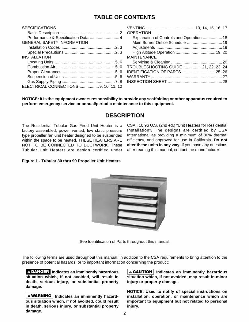
See Identification of Parts throughout this manual.
DESCRIPTION
The Residential Tubular Gas Fired Unit Heater is afactory assembled, power vented, low static pressuretype propeller fan unit heater designed to be suspendedwithin the space to be heated. THESE HEATERS ARENOT TO BE CONNECTED TO DUCTWORK. TheseTubular Unit Heaters are design certified under
Figure 1 - Tubular 30 thru 90 Propeller Unit Heaters
NOTICE: It is the equipment owners responsibility to provide any scaffolding or other apparatus required toperform emergency service or annual/periodic maintenance to this equipment.
CSA . 10.96 U.S. (2nd ed.) “Unit Heaters for ResidentialInstallation”. The designs are certified by CSAInternational as providing a minimum of 80% thermalefficiency, and approved for use in California. Do notalter these units in any way. If you have any questionsafter reading this manual, contact the manufacturer.
3
GENERAL SAFETY INFORMATION
Failure to comply with the generalsafety information may result in extensiveproperty damage, severe personal injury, ordeath.
This product must be installed bya licensed plumber or gas fitter when installedwithin the Commonwealth of Massachusetts.
Installation must be made in accordance with localcodes, or in absence of local codes, with ANSIStandard Z223.1-2002. (N.F.P.A. No. 54) National FuelGas Code, or the latest edition of. All of the ANSI andNFPA Standards referred to in these installationinstructions are those that were applicable at the timethe design of this appliance was certified. The ANSIStandards are available from the American GasAssociation, 1515 Wilson Boulevard, Arlington, Virginia22209. The NFPA Standards are available from theNational Fire Protection Association, Batterymarch Park,Quincy, MA 02269.
If installed in Canada, the installation must conform withlocal building codes, or in the absence of local buildingcodes, with CGA-B149.1 "Installation Codes for NaturalGas Burning Appliances and Equipment" or CGA-B149.2"Installation Codes for Propane Gas Burning Appliancesand Equipment." These unit heaters have been designedand certified to comply with CGA 2.6.
Do not alter the unit heater in anyway or damage to the unit and/or severe personalinjury or death may occur!
Disconnect all power and gassupplies before installing or servicing the heater.If the power disconnect is out of sight, lock it inthe open position and tag it to prevent unexpectedapplication of power. Failure to do so could resultin fatal electric shock, or severe personal injury.
Insure that all power sources conformto the requirements of the unit heater, or damage tothe unit will result!
Follow installation instructions CAREFULLY to avoidcreating unsafe conditions. All wiring should be doneand checked by a qualified electrician, using copper wireonly. All gas connections should be made and leak-tested by a suitably qualified individual, per instructionsin this manual. Also follow procedures listed on "GasEquipment Start-Up Sheet" located in this manual.
Use only the fuel for which the heater is designed (seerating plate). Using LP gas in a heater that requiresnatural gas, or vice versa, will create risk of gas leaks,carbon monoxide poisoning, and explosion.
Do not attempt to convert theheater for use with a fuel other than the oneintended. Such conversion is dangerous, as itwill create the risks previously listed.
Make certain that the power source conforms to theelectrical requirements of the heater.
Do not depend upon a thermostator other switch as sole means of disconnectingpower when installing or servicing heater. Alwaysdisconnect power at main circuit breaker asdescribed above. Failure to do so could result infatal electric shock.
Special attention must be given to any groundinginformation pertaining to this heater. To prevent the riskof electrocution, the heater must be securely andadequately grounded. This should be accomplished byconnecting a ground conductor between the service paneland the heater. To ensure a proper ground, the groundingmeans must be tested by a qualified electrician.
Do not insert fingers or foreign objects into heater or itsair moving device. Do not block or tamper with the heaterin any manner while in operation, or just after it has beenturned off, as some parts maybe hot enough to causeinjury.
This heater is intended for general heating applicationsONLY. It must NOT be used in potentially dangerouslocations such as flammable, explosive, chemical-laden,or wet atmospheres.
Do not attach ductwork to this product or use it as amakeup air heater. Such usage voids the warranty andwill create unsafe operation.
In cases in which property damage may result frommalfunction of the heater, a back-up system ortemperature sensitive alarm should be used.
The open end of piping systems beingpurged shall not discharge into areas where thereare sources of ignition or into confined spacesUNLESS precautions are taken as follows: (1) byventilation of the space, (2) control of the purgingrate, (3) elimination of all hazardous conditions. Allprecautions must be taken to perform this operationin a safe manner!
Unless otherwise specified, the following conversionsmay be used for calculating SI unit measurements:1 foot = 0.305 m1 inch = 25.4 mm1 gallon = 3.785 L1 pound = 0.453 kg1 psig = 6.894 kPa1 cubic foot = 0.028m3
1000 BTU/cu. ft. = 37.5 MJ/m3
1000 BTU per hour = 0.293 kW1 inch water column = 0.249 kPaliter/second = CFM x 0.472meters/second = FPM ÷ 196.8

4
Table 1 - Performance and Dimensional Data - Tubular 30 thru 90 Propeller Unit Heater
Figure 2 - Dimensional Drawing – Tubular 30 thru 90 Propeller Unit Heater
Unit Size 30 45 60 75 90PERFORMANCE DATA†Input - BTU/Hr. 30,000 45,000 60,000 75,000 90,000 (kW) (8.8) (13.2) (17.6) (22.0) (26.4)Output - BTU/Hr. 24,300 36,450 48,600 60,750 72,900 (kW) (7.1) (10.7) (14.2) (17.8) (21.4)Thermal Efficiency (%) 81 81 81 81 81Free Air Delivery - CFM 500 750 1,000 1,250 1,500 (cu. m/s) (0.236) (0.355) (0.473) (0.591) (0.710)Air Temperature Rise - Deg. F 45 45 45 45 45 (Deg. C) (25) (25) (25) (25) (25)Full Load Amps at 120V ** 3.0 3.0 3.7 3.7 4.8MOTOR DATA: Motor HP 1/20 1/20 1/20 1/20 1/20
Motor (kW) (0.37) (0.37) (0.37) (0.37) (0.37)Motor Type SP SP SP SP SPR.P.M. 1650 1650 1050 1050 1050Motor Amps @ 115V 1.9 1.9 2.6 2.6 2.6
DIMENSIONAL DATA - inches (mm)“A” Jacket Height 12 12 17-3/4 17-3/4 17-3/4
(305) (305) (451) (451) (451)“B” Overall Height 13 13 18-3/4 18-3/4 18-3/4
(330) (330) (476) (476) (476)“C” Overall Depth 25-1/2 25-1/2 26-3/4 26-3/4 26-3/4
(648) (648) (679) (679) (679)“Center Line” Height of Flue* 7-1/4 7-1/4 10-1/2 10-1/2 10-1/2
(184) (184) (267) (267) (267)“Center Line” Electric Connection 10-1/4 10-1/4 16 16 16
(260) (260) (406) (406) (406)“F” Discharge Opening Height 10-1/2 10-1/2 16-1/4 16-1/4 16-1/4
(267) (267) (413) (413) (413)“G” Fan Diameter-in 10 10 16 16 16Unit Weight - lbs. 62 68 87 93 95 (kgs) (28) (31) (39) (42) (43)Shipping Weight - lbs. 72 78 102 108 110 (kgs) (33) (35) (46) (49) (50)
DIMENSIONS .XXX STANDARD UNITSDIMENSIONS IN PARENTHESIS (XXX) MILLIMETERS
* Canadian unit includes the vent cap.
* For all installations, the flue collar is included with the unit and should be field installed per the instructions included with the unit.
† Ratings shown are for unit installations at elevations between 0 and 2,000 ft (0 to 610m). For unit installations in U.S.A. above 2,000 ft. (610m), the unit input must be derated 4% for each 1,000 ft. (305m) above sealevel; refer to local codes, or in absence of local codes, refer to the National Fuel Gas Code, ANSI Standard Z223.1-2002 (N.F.P.A. No. 54), or the latest edition (also refer to Table 4).
For installations in Canada, any reference to deration at altitudes in excess of 2,000 ft. (610m) are to be ignored. At altitudes of 2,000 ft. to 4,500 ft. (610 to 1372m), the unit must be derated to 90% of the normalaltitude rating, and be so marked in accordance with the CSA certification.
5
INSTALLATION
Do not install unit heaters incorrosive or flammable atmospheres! Prematurefailure of, or severe damage to the unit willresult!
Avoid locations where extremedrafts can affect burner operation. Unit heatersmust not be installed in locations where air forcombustion would contain chlorinated,halogenated or acidic vapors. If located in suchan environment, premature failure of the unitwill occur!
Since the unit is equipped with an automatic gas ignitionsystem, the unit heater must be installed such that thegas ignition control system is not directly exposed towater spray, rain or dripping water.
NOTICE: Location of unit heaters is related directlyto the selection of sizes. Basic rules are as follows:
MOUNTING HEIGHT: If the unit heater is installed in agarage, it must be installed with a minimum clearanceabove the floor of 18 inches (457mm).
AIR DISTRIBUTION: Direct air towards areas ofmaximum heat loss. When multiple heaters are involved,circulation of air around the perimeter is recommendedwhere heated air flows along exposed walls. Satisfactoryresults can also be obtained where multiple heaters arelocated toward the center of the area with heated airdirected toward the outside walls. Be careful to avoidall obstacles and obstructions which could impede thewarm air distribution patterns.
Unit heaters should not be installed to maintain lowtemperatures and/or freeze protection of buildings.A minimum of 50°F (10°C) thermostat setting mustbe maintained. If unit heaters are operated to maintainlower than 50°F (10°C), hot flue gases are cooled insidethe heat exchanger to a point where water vapor (a fluegas by-product) condenses onto the heat exchangerwalls. The result is a mildly corrosive acid thatprematurely corrodes the aluminized heat exchangerand can actually drip water down from the unit heateronto floor surface. Additional unit heaters should beinstalled if a minimum 50°F (10°C) thermostat settingcannot be maintained.
AIR FOR COMBUSTION: The unit heater shall beinstalled in a location in which the facilities for ventilationpermit satisfactory combustion of gas, proper venting,and the maintenance of ambient air at safe limits undernormal conditions of use. The unit heater shall be locatedin such a manner as not to interfere with propercirculation of air within the confined space. Whenbuildings are so tight that normal infiltration does notmeet air requirements, outside air shall be introducedper Sections 1.3.4.2 and 1.3.4.3 of ANSI Z223.1 forcombustion requirements. A permanent opening oropenings having a total free area of not less than onesquare inch per 5,000 BTU/Hr (1.5 kW) of total inputrating of all appliances within the space shall beprovided.
NOTICE: Unit Heater sizing should be based on heatloss calculations where the unit heater output equalsor exceeds heat loss.
CLEARANCES: Each Gas Unit Heater shall be locatedwith respect to building construction and other equipmentso as to permit access to the Unit Heater. Clearancebetween vertical walls and the vertical sides of the UnitHeater shall be no less than 1 inch (25.4mm). However,to ensure access to the control box and fan, a minimumof 18" (457mm) is required for the fan, and control boxside. A minimum clearance of 1 inch (25.4mm) must bemaintained between the top of the Unit Heater and theceiling. The bottom of the Unit Heater must be no lessthan 1 inch (25.4mm) from any combustible. Thedistance between the flue collector and any combustiblemust be no less than 1 inch (25.4mm). Also see AIRFOR COMBUSTION and VENTING sections.
NOTICE: Increasing the clearance distances maybe necessary if there is a possibility of distortion ordiscoloration of adjacent materials.
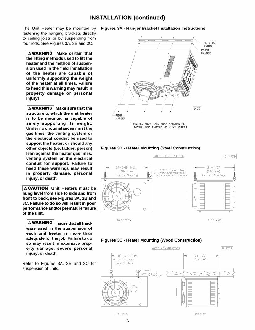
MOUNTING: The Unit Heater may be mounted with thevent outlet, gas and electrical connections to the rightor left of the air moving fan. The Unit Heater is shippedwith the connections to the right of the fan when lookingin the direction of the air flow. If connections to the rightare required, remove the (4) screws from the front topedge and the (5) screws from the rear top edge of theheater. Mount the hanging brackets (shipped loose inbottom of the carton) using the removed screws. Ifconnections to the left are required, invert the heater(180°), mount the hanging brackets as above, andremove, invert, and replace the control access paneland the air discharge louvers.
6
INSTALLATION (continued)
The Unit Heater may be mounted byfastening the hanging brackets directlyto ceiling joists or by suspending fromfour rods. See Figures 3A, 3B and 3C.
Make certain thatthe lifting methods used to lift theheater and the method of suspen-sion used in the field installationof the heater are capable ofuniformly supporting the weightof the heater at all times. Failureto heed this warning may result inproperty damage or personalinjury!
Make sure that thestructure to which the unit heateris to be mounted is capable ofsafely supporting its weight.Under no circumstances must thegas lines, the venting system orthe electrical conduit be used tosupport the heater; or should anyother objects (i.e. ladder, person)lean against the heater gas lines,venting system or the electricalconduit for support. Failure toheed these warnings may resultin property damage, personalinjury, or death.
Unit Heaters must behung level from side to side and fromfront to back, see Figures 3A, 3B and3C. Failure to do so will result in poorperformance and/or premature failureof the unit.
Insure that all hard-ware used in the suspension ofeach unit heater is more thanadequate for the job. Failure to doso may result in extensive prop-erty damage, severe personalinjury, or death!
Refer to Figures 3A, 3B and 3C forsuspension of units.
Figures 3C - Heater Mounting (Wood Construction)
Figures 3A - Hanger Bracket Installation Instructions
Figures 3B - Heater Mounting (Steel Construction)

7
GAS PIPING
To avoid damage or possible personal injury, do not connect gas piping to this unituntil a supply line pressure/leak test has been completed. Connecting the unit before completing thepressure/leak test may damage the unit gas valve and result in a fire hazard.Do not rely on a shut-off valve to isolate the unit while conducting gas pressure/leak tests. Thesevalves may not be completely shut off, exposing the gas valve to excessive pressure and damage.
NOTICE: If more than one unit heater is to be servedby the same piping arrangement, the total cu. ft./hr.input and length of pipe must be considered.
NOTICE: If the gas unit heater is to be fired with LPgas, consult your local LP gas dealer for pipe sizeinformation.
HEATER INSTALLATION FOR USE WITH PROPANE(BOTTLED) GAS MUST BE MADE BY A QUALIFIEDL.P. GAS DEALER OR INSTALLER. HE WILL ENSURETHAT PROPER JOINT COMPOUNDS ARE USED FORMAKING PIPE CONNECTIONS; THAT AIR IS PURGEDFROM LINES; THAT A THOROUGH TEST IS MADEFOR LEAKS BEFORE OPERATING THE HEATER;AND THAT IT IS PROPERLY CONNECTED TO THEPROPANE GAS SUPPLY SYSTEM.
Before any connection is made to the existing linesupplying other gas appliances, contact the local gascompany to make sure that the existing line is ofadequate size to handle the combined load.
1. Determine the required Cu. Ft./Hr. by dividing the input by 1000. For SI/Metric measurements: Convert BTU/Hr. to kilowatts. Multiply theunits inputs (kW) by 0.0965 to determine Cu. Meters./Hr. 2. FOR NATURAL GAS: Select pipe size directly from the table. 3. FOR PROPANEGAS: Multiply the Cu. Ft./Hr. value by 0.633; then, use the table. 4. Refer to the metric conversion factors listed in the General Safety sectionfor SI Unit measurement conversions.
Maximum Capacity of Pipe in Cubic Feet of Gas per Hour (Cubic Meters per Hour) for Gas Pressures of 0.5 psig (3.5 kPa) or Less,and a Pressure Drop of 0.5 Inch Water Column (124.4 Pa)
(Based on a 0.60 Specific Gravity Gas)Nominal
Iron Internal Length of Pipe, Feet (meters)
Pipe Size Dia. 10 20 30 40 50 60 70 80 90 100 125 150 175 200
in. in. (3.0) (6.1) (9.1) (12.2) (15.2) (18.3) (21.3) (24.4) (27.4) (30.5) (38.1) (45.7) (53.3) (61.0)
1/2 0.622 175 120 97 82 73 66 61 57 53 50 44 40 37 35(4.96) (3.40) (2.75) (2.32) (2.07) (1.87) (1.73) (1.61) (1.50) (1.42) (1.25) (1.13) (1.05) (0.99)
3/4 0.824 360 250 200 170 151 138 125 118 110 103 93 84 77 72(10.2) (7.08) (5.66) (4.81) (4.28) (3.91) (3.54) (3.34) (3.11) (2.92) (2.63) (2.38) (2.18) (2.04)
1 1.049 680 465 375 320 285 260 240 220 205 195 175 160 145 135(19.3) (13.2) (10.6) (9.06) (8.07) (7.36) (6.80) (6.23) (5.80) (5.52) (4.96) (4.53) (4.11) (3.82)
1 1/4 1.380 1400 950 770 660 580 530 490 460 430 400 360 325 300 280(39.6) (26.9) (21.8) (18.7) (16.4) (15.0) (13.9) (13.0) (12.2) (11.3) (10.2) (9.20) (8.50) (7.93)
1 1/2 1.610 2100 1460 1180 990 900 810 750 690 650 620 550 500 460 430(59.5) (41.3) (33.4) (28.0) (25.5) (22.9) (21.2) (19.5) (18.4) (17.6) (15.6) (14.2) (13.0) (12.2)
2 2.067 3950 2750 2200 1900 1680 1520 1400 1300 1220 1150 1020 950 850 800(112) (77.9) (62.3) (53.8) (47.6) (43.0) (39.6) (36.8) (34.5) (32.6) (28.9) (26.9) (24.1) (22.7)
2 1/2 2.469 6300 4350 3520 3000 2650 2400 2250 2050 1950 1850 1650 1500 1370 1280(178) (123) (99.7) (85.0) (75.0) (68.0) (63.7) (58.0) (55.2) (52.4) (46.7) (42.5) (38.8) (36.2)
3 3.068 11000 7700 6250 5300 4750 4300 3900 3700 3450 3250 2950 2650 2450 2280(311) (218) (177) (150) (135) (122) (110) (105) (97.7) (92.0) (83.5) (75.0) (69.4) (64.6)
4 4.026 23000 15800 12800 10900 9700 8800 8100 7500 7200 6700 6000 5500 5000 4600(651) (447) (362) (309) (275) (249) (229) (212) (204) (190) (170) (156) (142) (130)
Table 2 - Gas Pipe Size
PIPE SIZINGTo provide adequate gas pressure to the gas unit heater,size the gas piping as follows:
1. Find the cu. ft./hr. by using the following formula: Input
Cu. ft./hr. = BTU
2. Refer to Table 2. Match “Length of Pipe in Feet”with appropriate “Gas Input - Cu. Ft./Hr.” figure.This figure can then be matched to the pipe size atthe top of the column.Example:It is determined that a 67 foot (20.4m) run of gaspipe is required to connect a 75 MBTU gas unitheater to a 1,000 BTU/cu ft. (0.29kW) natural gassupply.
75,000 BTU/Hr = 75 Cu. ft./hr.
1,000 BTU/cu. ft.Using Table 2, a 3/4 inch pipe is needed.
NOTE: See General Safety Information section forEnglish/Metric unit conversion factors.

8
PIPE INSTALLATION
Do not over tighten the inlet gaspiping into the valve. This may cause stresses thatwill crack the valve!
NOTICE: Use pipe joint sealant resistant to the actionof liquefied petroleum gases regardless of gasconducted.
Check all pipe joints for leakageusing a soap solution or other approved method.Never use an open flame or severe personalinjury or death may occur!
Figure 4 - Pipe Installation, Standard Controls
Never use an open flame todetect gas leaks. Explosive conditions may existwhich may result in personal injury or death!
The appliance and its individual shutoff valve must bedisconnected from the gas supply piping system duringany pressure testing of that system in excess of 1/2psig (3.5 kPa).
The appliance must be isolated from the gas supplypiping system by closing its individual manual shutoffvalve during any pressure testing of the gas supplypiping system at test pressures equal to or less than1/2 psig (3.5 kPa).
1. Install the gas piping in accordance with applicablelocal codes.
2. Check gas supply pressure. Each unit heater mustbe connected to a gas supply capable of supplyingits full rated capacity as specified in Table 3A. Afield LP tank regulator must be used to limit thesupply pressure to a maximum of 14 in. W.C. (3.5kPa). All piping should be sized in accordance withANSI Standard Z223.1-2002, (or the latest edition)National Fuel Gas Code; in Canada, according toCGA-B149. See Tables 1 & 2 for correct gas pipingsize, and also refer to Tables 3A, 3B and 4. If gaspressure is excessive on natural gas applications,install a pressure regulating valve in the lineupstream from the main shutoff valve.
3. Adequately support the piping to prevent strain onthe gas manifold and controls.
4. To prevent the mixing of moisture with gas, run thetake-off piping from the top, or side, of the main.
5. Standard Unit Heaters are supplied with acombination valve which includes:a. Manual "A" valveb. Manual "B" valvec. Solenoid valved. Pilot safetye. Pressure regulatorPipe directly into the combination valve (see Figure4).
6. A 1/8" N.P.T. plugged tapping, accessible for testgauge connection, must be installed immediatelyupstream of the gas supply connection to theappliance.
7. Provide a drip leg in the gas piping near the gasunit heater. A ground joint union and a manual gasshutoff valve should be installed ahead of the unitheater controls to permit servicing. The manualshutoff valve must be located external to the jacket.(See Figure 4)
8. Make certain that all connections have beenadequately doped and tightened.
Table 3A - Gas Piping Requirements
SINGLE STAGE GAS PIPING REQUIREMENTS*
GasType Natural Gas Propane (LP) Gas
Manifold 3.5 in. W.C. 10.0 in. W.C.Pressure (0.9 kPa) (2.5 kPa)
14.0 in. W.C. Max. 14.0 in. W.C. Max.Supply Inlet (3.5 kPa) (3.5 kPa)Pressure 5.0 in. W.C. Min. 11.0 in W.C. Min.
(1.2 kPa) (2.7 kPa)
*For single stage application only at normal altitudes.
9
ELECTRICAL CONNECTIONS
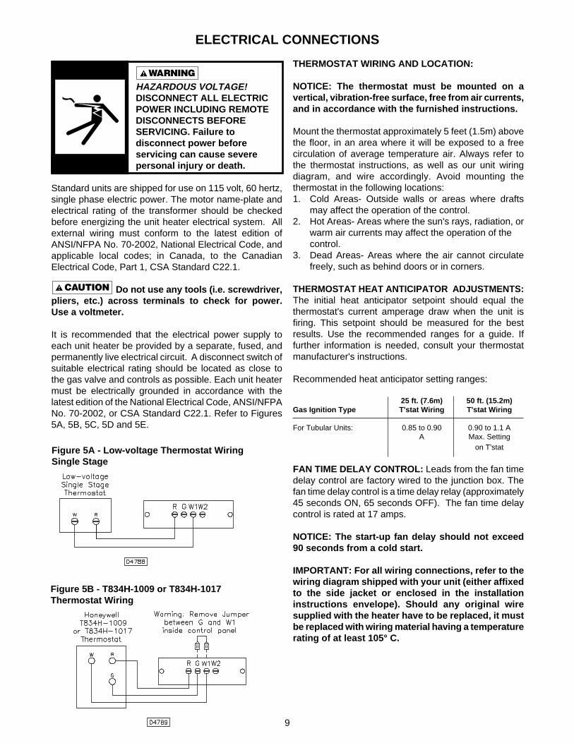
THERMOSTAT WIRING AND LOCATION:
NOTICE: The thermostat must be mounted on avertical, vibration-free surface, free from air currents,and in accordance with the furnished instructions.
Mount the thermostat approximately 5 feet (1.5m) abovethe floor, in an area where it will be exposed to a freecirculation of average temperature air. Always refer tothe thermostat instructions, as well as our unit wiringdiagram, and wire accordingly. Avoid mounting thethermostat in the following locations:1. Cold Areas- Outside walls or areas where drafts
may affect the operation of the control.2. Hot Areas- Areas where the sun's rays, radiation, or
warm air currents may affect the operation of thecontrol.
3. Dead Areas- Areas where the air cannot circulatefreely, such as behind doors or in corners.
THERMOSTAT HEAT ANTICIPATOR ADJUSTMENTS:The initial heat anticipator setpoint should equal thethermostat's current amperage draw when the unit isfiring. This setpoint should be measured for the bestresults. Use the recommended ranges for a guide. Iffurther information is needed, consult your thermostatmanufacturer's instructions.
Recommended heat anticipator setting ranges:
25 ft. (7.6m) 50 ft. (15.2m)Gas Ignition Type T'stat Wiring T'stat Wiring
For Tubular Units: 0.85 to 0.90 0.90 to 1.1 AA Max. Setting
on T'stat
FAN TIME DELAY CONTROL: Leads from the fan timedelay control are factory wired to the junction box. Thefan time delay control is a time delay relay (approximately45 seconds ON, 65 seconds OFF). The fan time delaycontrol is rated at 17 amps.
NOTICE: The start-up fan delay should not exceed90 seconds from a cold start.
IMPORTANT: For all wiring connections, refer to thewiring diagram shipped with your unit (either affixedto the side jacket or enclosed in the installationinstructions envelope). Should any original wiresupplied with the heater have to be replaced, it mustbe replaced with wiring material having a temperaturerating of at least 105° C.
Figure 5B - T834H-1009 or T834H-1017Thermostat Wiring
Figure 5A - Low-voltage Thermostat WiringSingle Stage
HAZARDOUS VOLTAGE!DISCONNECT ALL ELECTRICPOWER INCLUDING REMOTEDISCONNECTS BEFORESERVICING. Failure todisconnect power beforeservicing can cause severepersonal injury or death.
Standard units are shipped for use on 115 volt, 60 hertz,single phase electric power. The motor name-plate andelectrical rating of the transformer should be checkedbefore energizing the unit heater electrical system. Allexternal wiring must conform to the latest edition ofANSI/NFPA No. 70-2002, National Electrical Code, andapplicable local codes; in Canada, to the CanadianElectrical Code, Part 1, CSA Standard C22.1.
Do not use any tools (i.e. screwdriver,pliers, etc.) across terminals to check for power.Use a voltmeter.
It is recommended that the electrical power supply toeach unit heater be provided by a separate, fused, andpermanently live electrical circuit. A disconnect switch ofsuitable electrical rating should be located as close tothe gas valve and controls as possible. Each unit heatermust be electrically grounded in accordance with thelatest edition of the National Electrical Code, ANSI/NFPANo. 70-2002, or CSA Standard C22.1. Refer to Figures5A, 5B, 5C, 5D and 5E.

10
ELECTRICAL CONNECTIONS (continued)
Figure 5C - Tubular Propeller Units Equipped with (Alternate) SV9500/9600/SV9501/SV9601 Gas Valve Module:Tubular 30 thru 90 Unit Sizes with Natural and Propane (LP) Gas
NOTICE: See Figures 5A, 5B, 5C, 5D and5E for connecting the thermostat to theunit heater. If using a standard low voltagethermostat with a sub-base switch for fancontrol, a relay must be added. Removethe jumper between G and W1 and movethe blue wire from G to W1 on the unitheater terminal block. Connect the relaycoil to G and the 24 volt common side ofthe transformer (white wires). Connectrelay switch to terminals 1 and 3 of fantime delay switch. Connect the G terminalof the thermostat to the G terminal of theunit heater.

11
ELECTRICAL CONNECTIONS (continued)
Figure 5D - Tubular Propeller Units Equipped with (Primary) SV9540/SV9640 Gas Valve Module:Tubular 30 thru 90 Unit Sizes with Natural and Propane (LP) Gas
12
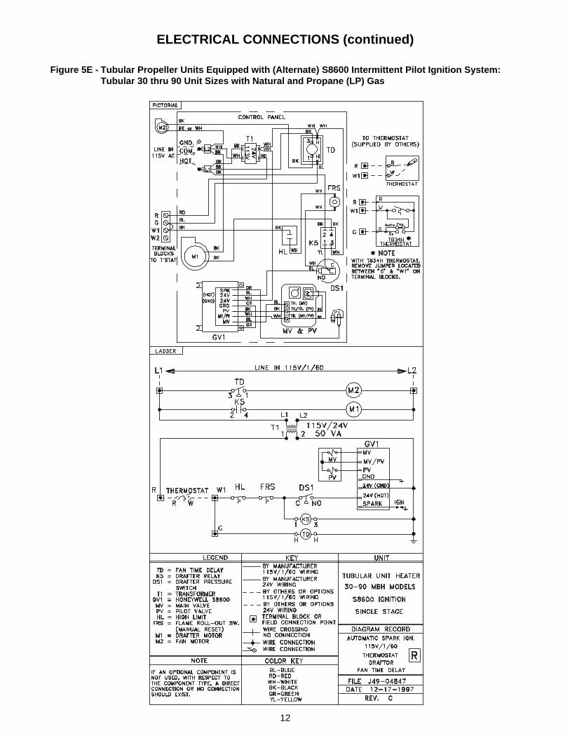
ELECTRICAL CONNECTIONS (continued)
Figure 5E - Tubular Propeller Units Equipped with (Alternate) S8600 Intermittent Pilot Ignition System:Tubular 30 thru 90 Unit Sizes with Natural and Propane (LP) Gas
13
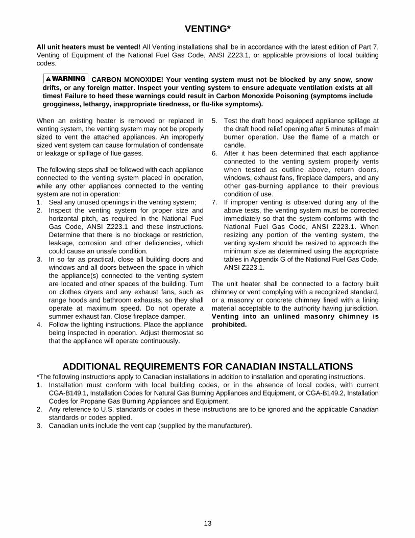
VENTING*
All unit heaters must be vented! All Venting installations shall be in accordance with the latest edition of Part 7,Venting of Equipment of the National Fuel Gas Code, ANSI Z223.1, or applicable provisions of local buildingcodes.
CARBON MONOXIDE! Your venting system must not be blocked by any snow, snowdrifts, or any foreign matter. Inspect your venting system to ensure adequate ventilation exists at alltimes! Failure to heed these warnings could result in Carbon Monoxide Poisoning (symptoms includegrogginess, lethargy, inappropriate tiredness, or flu-like symptoms).
When an existing heater is removed or replaced inventing system, the venting system may not be properlysized to vent the attached appliances. An improperlysized vent system can cause formulation of condensateor leakage or spillage of flue gases.
The following steps shall be followed with each applianceconnected to the venting system placed in operation,while any other appliances connected to the ventingsystem are not in operation:1. Seal any unused openings in the venting system;2. Inspect the venting system for proper size and
horizontal pitch, as required in the National FuelGas Code, ANSI Z223.1 and these instructions.Determine that there is no blockage or restriction,leakage, corrosion and other deficiencies, whichcould cause an unsafe condition.
3. In so far as practical, close all building doors andwindows and all doors between the space in whichthe appliance(s) connected to the venting systemare located and other spaces of the building. Turnon clothes dryers and any exhaust fans, such asrange hoods and bathroom exhausts, so they shalloperate at maximum speed. Do not operate asummer exhaust fan. Close fireplace damper.
4. Follow the lighting instructions. Place the appliancebeing inspected in operation. Adjust thermostat sothat the appliance will operate continuously.
5. Test the draft hood equipped appliance spillage atthe draft hood relief opening after 5 minutes of mainburner operation. Use the flame of a match orcandle.
6. After it has been determined that each applianceconnected to the venting system properly ventswhen tested as outline above, return doors,windows, exhaust fans, fireplace dampers, and anyother gas-burning appliance to their previouscondition of use.
7. If improper venting is observed during any of theabove tests, the venting system must be correctedimmediately so that the system conforms with theNational Fuel Gas Code, ANSI Z223.1. Whenresizing any portion of the venting system, theventing system should be resized to approach theminimum size as determined using the appropriatetables in Appendix G of the National Fuel Gas Code,ANSI Z223.1.
The unit heater shall be connected to a factory builtchimney or vent complying with a recognized standard,or a masonry or concrete chimney lined with a liningmaterial acceptable to the authority having jurisdiction.Venting into an unlined masonry chimney isprohibited.
ADDITIONAL REQUIREMENTS FOR CANADIAN INSTALLATIONS*The following instructions apply to Canadian installations in addition to installation and operating instructions.1. Installation must conform with local building codes, or in the absence of local codes, with current
CGA-B149.1, Installation Codes for Natural Gas Burning Appliances and Equipment, or CGA-B149.2, InstallationCodes for Propane Gas Burning Appliances and Equipment.
2. Any reference to U.S. standards or codes in these instructions are to be ignored and the applicable Canadianstandards or codes applied.
3. Canadian units include the vent cap (supplied by the manufacturer).
14
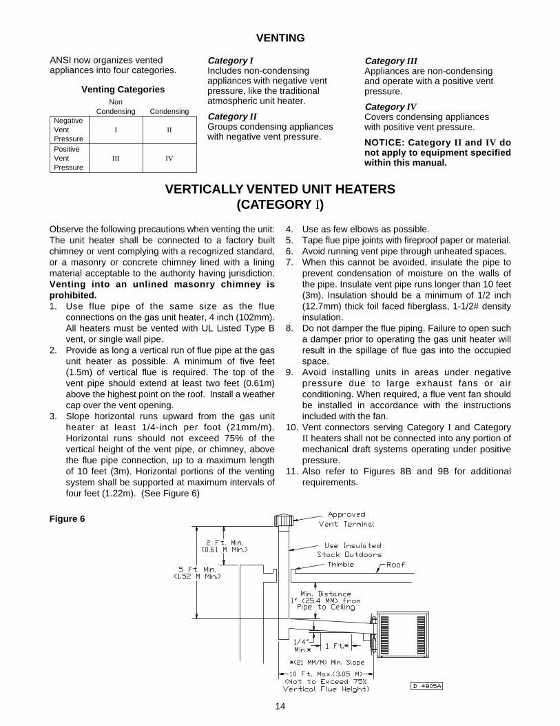
VERTICALLY VENTED UNIT HEATERS(CATEGORY I)
Observe the following precautions when venting the unit:The unit heater shall be connected to a factory builtchimney or vent complying with a recognized standard,or a masonry or concrete chimney lined with a liningmaterial acceptable to the authority having jurisdiction.Venting into an unlined masonry chimney isprohibited.1. Use flue pipe of the same size as the flue
connections on the gas unit heater, 4 inch (102mm).All heaters must be vented with UL Listed Type Bvent, or single wall pipe.
2. Provide as long a vertical run of flue pipe at the gasunit heater as possible. A minimum of five feet(1.5m) of vertical flue is required. The top of thevent pipe should extend at least two feet (0.61m)above the highest point on the roof. Install a weathercap over the vent opening.
3. Slope horizontal runs upward from the gas unitheater at least 1/4-inch per foot (21mm/m).Horizontal runs should not exceed 75% of thevertical height of the vent pipe, or chimney, abovethe flue pipe connection, up to a maximum lengthof 10 feet (3m). Horizontal portions of the ventingsystem shall be supported at maximum intervals offour feet (1.22m). (See Figure 6)
4. Use as few elbows as possible.5. Tape flue pipe joints with fireproof paper or material.6. Avoid running vent pipe through unheated spaces.7. When this cannot be avoided, insulate the pipe to
prevent condensation of moisture on the walls ofthe pipe. Insulate vent pipe runs longer than 10 feet(3m). Insulation should be a minimum of 1/2 inch(12.7mm) thick foil faced fiberglass, 1-1/2# densityinsulation.
8. Do not damper the flue piping. Failure to open sucha damper prior to operating the gas unit heater willresult in the spillage of flue gas into the occupiedspace.
9. Avoid installing units in areas under negativepressure due to large exhaust fans or airconditioning. When required, a flue vent fan shouldbe installed in accordance with the instructionsincluded with the fan.
10. Vent connectors serving Category I and CategoryII heaters shall not be connected into any portion ofmechanical draft systems operating under positivepressure.
11. Also refer to Figures 8B and 9B for additionalrequirements.
Figure 6
VENTING
ANSI now organizes ventedappliances into four categories.
Category IIncludes non-condensingappliances with negative ventpressure, like the traditionalatmospheric unit heater.
Category IIGroups condensing applianceswith negative vent pressure.
Venting CategoriesNon
Condensing CondensingNegativeVent I IIPressurePositiveVent III IVPressure
Category IIIAppliances are non-condensingand operate with a positive ventpressure.
Category IVCovers condensing applianceswith positive vent pressure.
NOTICE: Category II and IV donot apply to equipment specifiedwithin this manual.

15
HORIZONTALLY VENTED UNIT HEATERS (CATEGORY III)
All venting of residential tubular unitheaters must comply with the latestedition of CSA . 10.96 U.S. (2nd ed.)requirement.
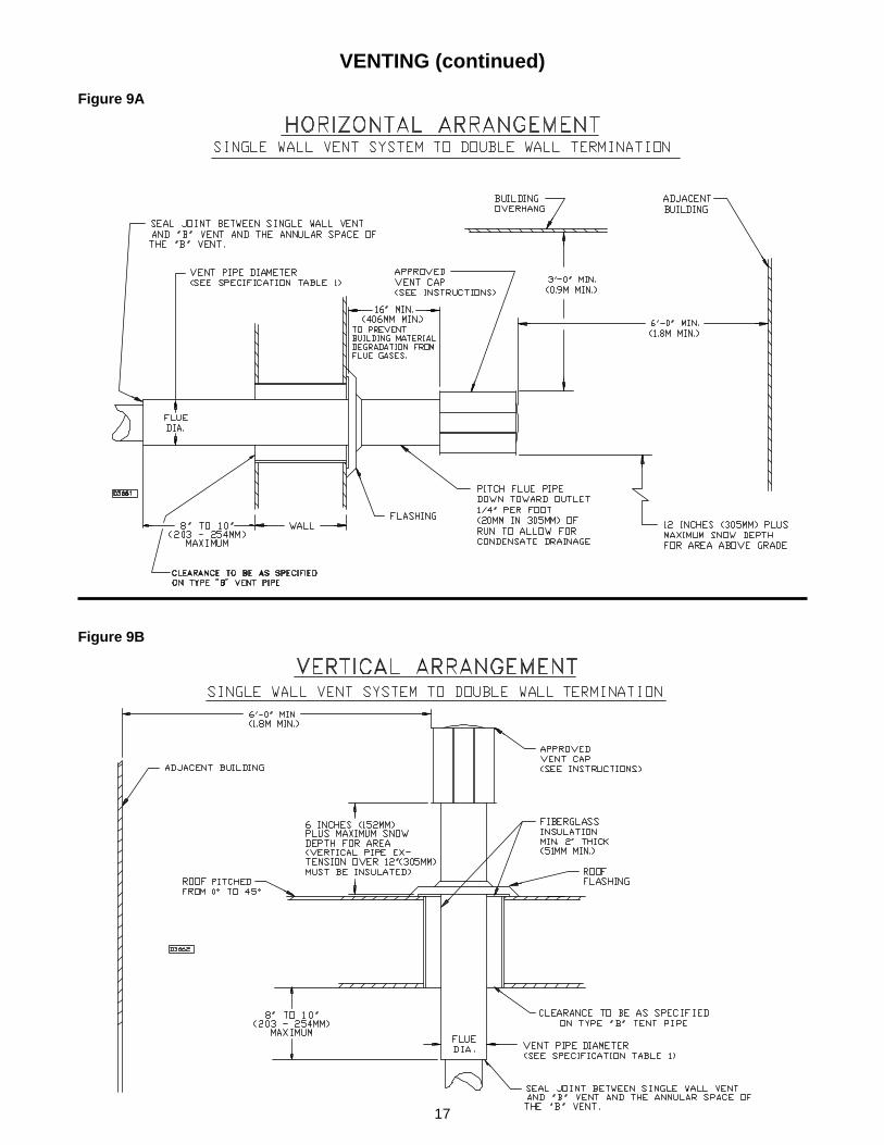
Horizontal venting arrangements aredesigned to be used with single wallvent pipe. These arrangements mustterminate external to the buildingusing either single wall or double wall(Type B) vent. See Figures 7, 8Aand 9A for special installationrequirements regarding theseventing conditions.
TYPE B(DOUBLE WALL) VENT TOTYPE B VENT CONNECTIONSARE NOT ALLOWED INTER-NALLY WITHIN THE BUILD-INGS ON HORIZONTALLYVENTED POWER VENTEDUNITS.
TRANSITIONS FROM THERECOMMENDED SINGLEWALL TO TYPE B VENT PIPEIS ONLY ALLOWED INTER-NALLY WITHIN THE BUILDINGAT THE POINT OF BUILDINGTERMINATION.
If double wall venting is used,components which are UL Listed andapproved for Category III positivepressure venting systems MUST beused.
A Breidert Type L, Fields Starkap,or equivalent vent cap must besupplied by the customer for eachpower vented unit (Canadian unitsare equipped with the vent cap). Thevent pipe diameter MUST be 4inches (102mm).
Figure 7
The venting system for theseappliances shall terminate at leastfour feet (1.2m) below, four feet(1.2m) horizontal from, or one foot(0.3m) above any door, window, orgravity vent air inlet into the building.
The vent terminal must be at least12 inches (305mm) from the exteriorof the wall that it passes through toprevent degradation of the buildingmaterial by flue gases.
The vent terminal must be at least 1foot (305mm) above grade, or insnow areas, at least three feet abovethe snow line to prevent blockageby snow.
Through the wall vent for theseappliances shall NOT terminate overpublic walkways, or over an areawhere the condensate or vapor couldcreate a nuisance or hazard or couldbe detrimental to the operation ofregulators, relief valves, or otherequipment.
The vent pipe equivalent length mustnot exceed 30 feet (9.14m) for the30 and 45 unit sizes, and 40 feet(12.2m) for the 60 and 75 unit sizes.Equivalent length is the total lengthof straight sections PLUS 5 feet(1.52m) for each 90 elbow and 2.5feet (0.76m) for each 45 elbow.
Maintain 1 inch (25.4mm) betweenthe vent pipe and combustiblematerials.
The vent terminal must be installedwith a minimum horizontal clearanceof four feet (1.2m) from electricmeters, gas meters, regulators, andrelief equipment.
Seal all vent pipe joints and seams toprevent leakage.Use General ElectricRTV-108, Dow-Corning RTV-732silicone sealant; or 3M #425aluminum foil tape. The vent airsystem must be installed to preventcollection of condensate. Pitchhorizontal pipes downward 1/4 inchper foot (21mm per meter) toward theoutlet for condensate drainage
Horizontal portions of the ventingsystems shall be supported atmaximum intervals of four feet(1.2m) to prevent sagging (inCanada, support at 3 feet (1m)minimum intervals).
Insulate single wall vent pipeexposed to cold air or runningthrough unheated areas. Insulatevent pipe runs longer than 10 feet(3m). Insulation should be a minmumof 1/2 inch thick foil faced fiberglass,1-1/2# density insulation.
Each unit must have an individualvent pipe and vent terminal! Eachunit MUST NOT be connected toother vent systems or to a chimney.
Door, window orany gravity air inlet
Forced air inlet within 10 ft.
Adjoining building or parapet
Adjacent public walkways
MinimumClearances forTerminationLocations
Structure
4 feetbelow
4 feethorizontally
1 footabove
3 feetabove
6 feet
7 feetabove grade
Vent SystemsTermination Clearance Requirements

16
Figure 8A
Figure 8B
VENTING (continued)
17
VENTING (continued)
Figure 9A
Figure 9B
18
OPERATIONPOWER VENTED PROPELLER UNITS
INTERMITTENT PILOT IGNITION
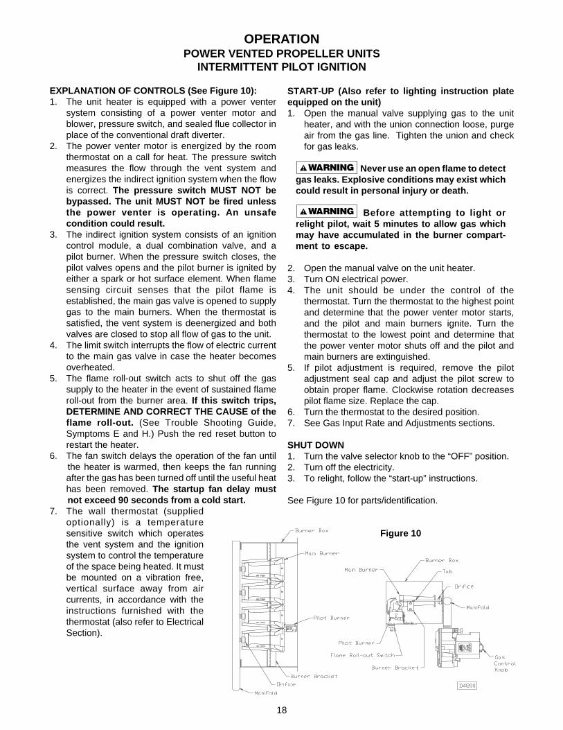
EXPLANATION OF CONTROLS (See Figure 10):1. The unit heater is equipped with a power venter
system consisting of a power venter motor andblower, pressure switch, and sealed flue collector inplace of the conventional draft diverter.
2. The power venter motor is energized by the roomthermostat on a call for heat. The pressure switchmeasures the flow through the vent system andenergizes the indirect ignition system when the flowis correct. The pressure switch MUST NOT bebypassed. The unit MUST NOT be fired unlessthe power venter is operating. An unsafecondition could result.
3. The indirect ignition system consists of an ignitioncontrol module, a dual combination valve, and apilot burner. When the pressure switch closes, thepilot valves opens and the pilot burner is ignited byeither a spark or hot surface element. When flamesensing circuit senses that the pilot flame isestablished, the main gas valve is opened to supplygas to the main burners. When the thermostat issatisfied, the vent system is deenergized and bothvalves are closed to stop all flow of gas to the unit.
4. The limit switch interrupts the flow of electric currentto the main gas valve in case the heater becomesoverheated.
5. The flame roll-out switch acts to shut off the gassupply to the heater in the event of sustained flameroll-out from the burner area. If this switch trips,DETERMINE AND CORRECT THE CAUSE of theflame roll-out. (See Trouble Shooting Guide,Symptoms E and H.) Push the red reset button torestart the heater.
6. The fan switch delays the operation of the fan untilthe heater is warmed, then keeps the fan runningafter the gas has been turned off until the useful heathas been removed. The startup fan delay mustnot exceed 90 seconds from a cold start.
7. The wall thermostat (suppliedoptionally) is a temperaturesensitive switch which operatesthe vent system and the ignitionsystem to control the temperatureof the space being heated. It mustbe mounted on a vibration free,vertical surface away from aircurrents, in accordance with theinstructions furnished with thethermostat (also refer to ElectricalSection).
START-UP (Also refer to lighting instruction plateequipped on the unit)1. Open the manual valve supplying gas to the unit
heater, and with the union connection loose, purgeair from the gas line. Tighten the union and checkfor gas leaks.
Never use an open flame to detectgas leaks. Explosive conditions may exist whichcould result in personal injury or death.
Before attempting to light orrelight pilot, wait 5 minutes to allow gas whichmay have accumulated in the burner compart-ment to escape.
2. Open the manual valve on the unit heater.3. Turn ON electrical power.4. The unit should be under the control of the
thermostat. Turn the thermostat to the highest pointand determine that the power venter motor starts,and the pilot and main burners ignite. Turn thethermostat to the lowest point and determine thatthe power venter motor shuts off and the pilot andmain burners are extinguished.
5. If pilot adjustment is required, remove the pilotadjustment seal cap and adjust the pilot screw toobtain proper flame. Clockwise rotation decreasespilot flame size. Replace the cap.
6. Turn the thermostat to the desired position.7. See Gas Input Rate and Adjustments sections.
SHUT DOWN1. Turn the valve selector knob to the “OFF” position.2. Turn off the electricity.3. To relight, follow the “start-up” instructions.
See Figure 10 for parts/identification.
Figure 10
19
PRIMARY AIR SHUTTER ADJUSTMENT
Primary air adjustment is made at the factory. No field adjustments are necessary.
GAS INPUT RATE
Check the gas input rate as follows (Refer to GeneralSafety Information section for metric conversions).
Never overfire the unit heater, as thismay cause unsatisfactory operation, or shorten thelife of the heater.
1. Turn off all gas appliances that use gas through thesame meter as the unit heater.
2. Turn the gas on to the unit heater.3. Clock the time in seconds required to burn 1 cubic
foot of gas by checking the gas meter.4. Insert the time required to burn one cubic foot of
gas into the following formula and compute the inputrate.
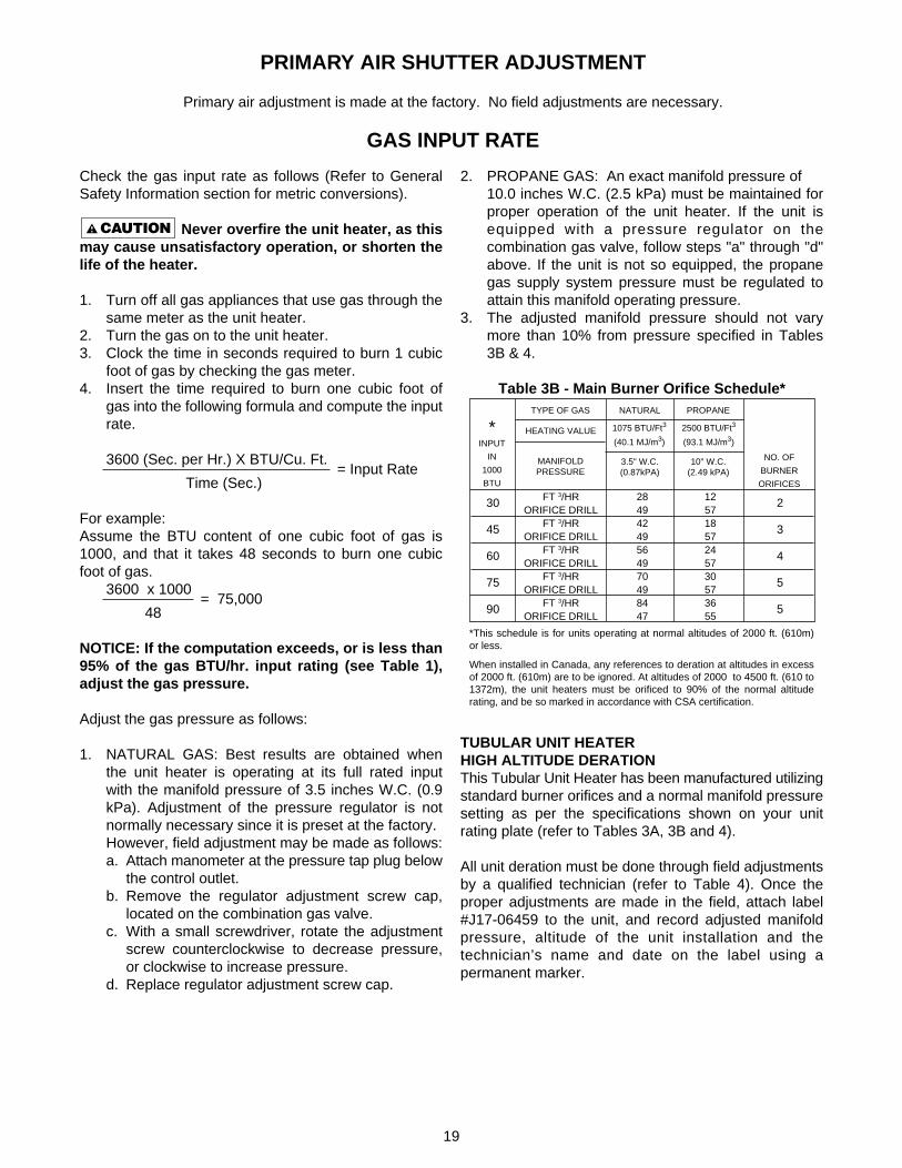
3600 (Sec. per Hr.) X BTU/Cu. Ft. = Input Rate
Time (Sec.)
For example:Assume the BTU content of one cubic foot of gas is1000, and that it takes 48 seconds to burn one cubicfoot of gas.
3600 x 1000 = 75,000
48
NOTICE: If the computation exceeds, or is less than95% of the gas BTU/hr. input rating (see Table 1),adjust the gas pressure.
Adjust the gas pressure as follows:
1. NATURAL GAS: Best results are obtained whenthe unit heater is operating at its full rated inputwith the manifold pressure of 3.5 inches W.C. (0.9kPa). Adjustment of the pressure regulator is notnormally necessary since it is preset at the factory.However, field adjustment may be made as follows:a. Attach manometer at the pressure tap plug below
the control outlet.b. Remove the regulator adjustment screw cap,
located on the combination gas valve.c. With a small screwdriver, rotate the adjustment
screw counterclockwise to decrease pressure,or clockwise to increase pressure.
d. Replace regulator adjustment screw cap.
2. PROPANE GAS: An exact manifold pressure of10.0 inches W.C. (2.5 kPa) must be maintained forproper operation of the unit heater. If the unit isequipped with a pressure regulator on thecombination gas valve, follow steps "a" through "d"above. If the unit is not so equipped, the propanegas supply system pressure must be regulated toattain this manifold operating pressure.
3. The adjusted manifold pressure should not varymore than 10% from pressure specified in Tables3B & 4.
Table 3B - Main Burner Orifice Schedule*
TUBULAR UNIT HEATERHIGH ALTITUDE DERATIONThis Tubular Unit Heater has been manufactured utilizingstandard burner orifices and a normal manifold pressuresetting as per the specifications shown on your unitrating plate (refer to Tables 3A, 3B and 4).
All unit deration must be done through field adjustmentsby a qualified technician (refer to Table 4). Once theproper adjustments are made in the field, attach label#J17-06459 to the unit, and record adjusted manifoldpressure, altitude of the unit installation and thetechnician’s name and date on the label using apermanent marker.
*INPUT
IN
1000
BTU
2500 BTU/Ft3
(93.1 MJ/m3)
PROPANETYPE OF GAS NATURAL
1075 BTU/Ft3
(40.1 MJ/m3)
3.5" W.C.(0.87kPA)
10" W.C.(2.49 kPA)
NO. OF
BURNER
ORIFICES
MANIFOLDPRESSURE
2
3
4
5
5
30
45
60
75
90
FT 3/HRORIFICE DRILL
FT 3/HRORIFICE DRILL
FT 3/HRORIFICE DRILL
FT 3/HRORIFICE DRILL
FT 3/HRORIFICE DRILL
28494249564970498447
12571857245730573655
HEATING VALUE
*This schedule is for units operating at normal altitudes of 2000 ft. (610m)or less.
When installed in Canada, any references to deration at altitudes in excessof 2000 ft. (610m) are to be ignored. At altitudes of 2000 to 4500 ft. (610 to1372m), the unit heaters must be orificed to 90% of the normal altituderating, and be so marked in accordance with CSA certification.
20
NATURAL GAS
MAINTENANCE
PERIODIC SERVICE
NOTICE: The heater and vent system should bechecked once a year by a qualified technician.
All Maintenance/Service information should be recordedaccordingly on the Inspection Sheet provided in thismanual.
Open all disconnect switches anddisconnect all electrical and gas supplies andsecure in that position before servicing unit.Failure to do so may result in personal injury ordeath from electrical shock.
Should maintenance be required, perform the followinginspection and service routine:
1. Inspect the area near the unit to be sure that thereis no combustible material located within theminimum clearance requirements listed in thismanual.
Under no circumstances shouldcombustible material be located within theclearances specified in this manual. Failure toprovide proper clearance could result inpersonal injury or equipment damage from fire.
2. Turn off the manual gas valve and electrical powerto the unit heater.
3. Remove service panel.4. To clean or replace the main burners, remove the
four screws holding the manifold to the burner boxand pull the manifold back slightly to disengage theorifices from the main burners. Remove each burnerby holding it against the tab on the burner bracket,then rotate the inlet end of the burner toward thefan side of the unit and slide the burner off the tabs.See Figure 10.
5. With the burners removed, wire brush the insidesurfaces of the heat exchanger.
6. Remove any dirt, dust, or other foreign matter fromthe burners using a wire brush and/or compressedair. Ensure that all parts are unobstructed. Inspectand clean the pilot burner if necessary.
7. Reassemble the unit heater by replacing all parts inreverse order.
8. Complete the appropriate unit startup procedure asgiven in the "Operation" section of this manual. (Seelighting instruction on the unit nameplate).
9. Check the burner adjustment.10. Check all gas control valves and pipe connections
for leaks.11 Check the operation of the automatic gas valve by
lowering the setting of the thermostat, stopping theoperation of the gas unit heater. The gas valveshould close tightly, completely extinguishing theflame on the main burners.
12. Inspect and service motor/fan assembly. To maintainefficient air flow, inspect and clean the fan bladesand guard to prevent buildup of foreign matter.
13. Check lubrication instructions on motor. If oiling isrequired, add 3 or 4 drops of electric motor oil asfollows:a. Light Duty - After 3 years or 25,000 hours of
operation.b. Average Duty - Annually after 3 years or 8,000
hours of operation.c. Heavy Duty - Annually after 1 years or at least
1500 hours of operation.
Never over oil the motor or prematurefailure may occur!
14. Check and test the operational functions of all safetydevices supplied with your unit.
ManifoldPressure(In. W.C.)
*HeatingValue
BTU/Cu. ft.
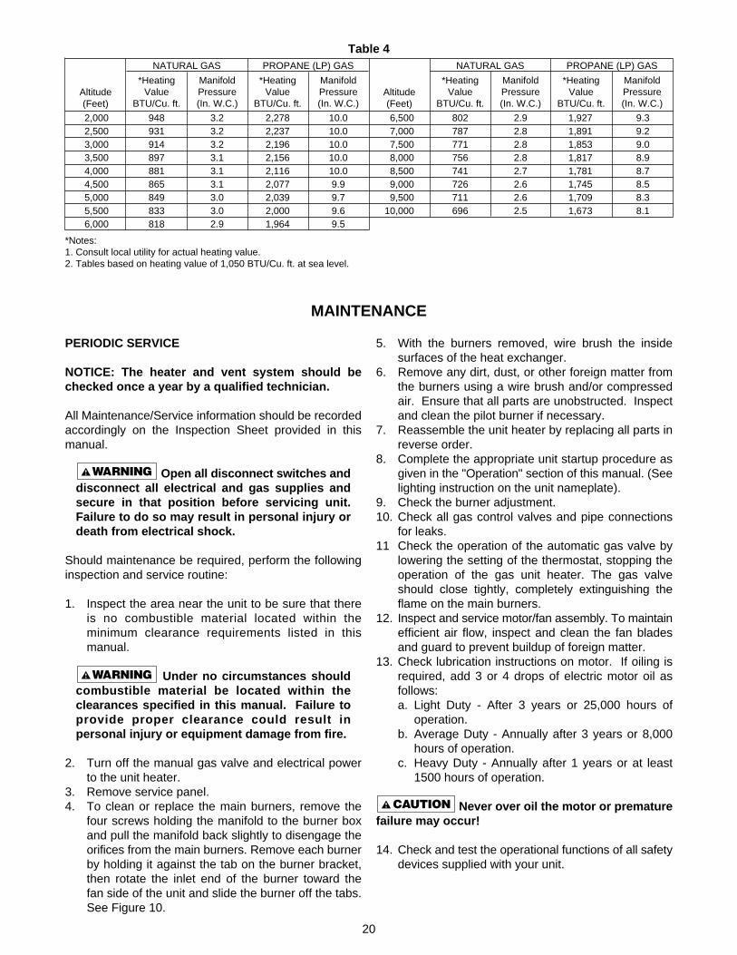
9.39.29.08.98.78.58.38.1
1,9271,8911,8531,8171,7811,7451,7091,673
2.92.82.82.82.72.62.62.5
6,500 7,000 7,500 8,000 8,500 9,000 9,50010,000
802787771756741726711696
ManifoldPressure(In. W.C.)
PROPANE (LP) GAS
*HeatingValue
BTU/Cu. ft.Altitude(Feet)
Table 4
ManifoldPressure(In. W.C.)
*HeatingValue
BTU/Cu. ft.
10.010.010.010.010.09.99.79.69.5
2,2782,2372,1962,1562,1162,0772,0392,0001,964
3.23.23.23.13.13.13.03.02.9
2,000 2,500 3,000 3,500 4,000 4,500 5,000 5,500 6,000
948931914897881865849833818
ManifoldPressure(In. W.C.)
PROPANE (LP) GASNATURAL GAS
*HeatingValue
BTU/Cu. ft.Altitude(Feet)
*Notes:1. Consult local utility for actual heating value.2. Tables based on heating value of 1,050 BTU/Cu. ft. at sea level.

21
1. Pressure regulator set too high.
2. Defective Regulator.
3. Burner orifice too large.
1. Burner orifice too small.
1. Noisy pilot2. Irregular orifice causing whistle or resonance.3. Excessive gas input.
1. Clogged main burner ports.2. Misaligned orifices.3. Insufficient combustion air.
1. Blocked venting.2. Insufficient combustion air.
3. Blocked heat exchanger.4. Air leak into combustion chamber or
draft hood.
1. Shut off gas supply immediately!2. Blocked heat exchanger.3. Drafts around heater.4. Negative Pressure in building.5. Blocked draft hood.
1. Main burner ports clogged near pilot.2. Pressure regulator set too low.
3. Pilot decreases in size when mainburnerscome on.
4. Pilot flame too small.5. Drafts around heater.6. Improper venting.
1. Main gas off.2. Lack of power at unit.3. Thermostat not calling for heat.4. Defective limit switch.
5. Improper thermostat or transformer wiringat gas valve.
6. Defective gas valve.7. Defective thermostat
8. Defective transformer.
9. Loose wiring.
10. Defective ignition control.
11. Flame roll-out switch tripped, seeSymptom E.
1. Improper venting.
1. Poor thermostat location.2. Defective thermostat3. Improper thermostat or transformer wiring at
gas valve.4. Short circuit.
5. Defective or sticking gas valve.6. Excessive gas supply pressure.
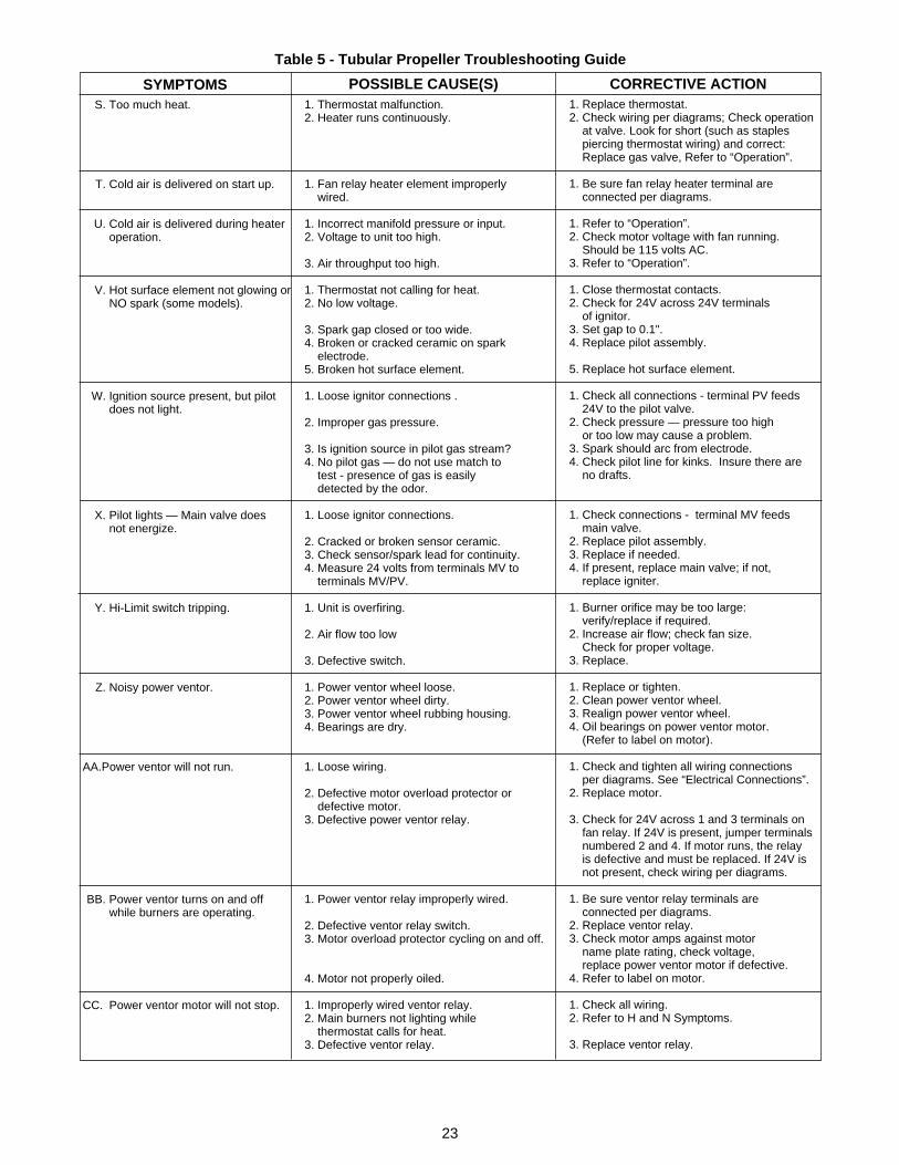
Table 5 - Tubular Propeller Troubleshooting Guide
1. Reset manifold pressure.Refer to “Operation”.
2. Replace regulator section of combinationgas valve or complete valve.
3. Check with local gas supplier for properorifice size and replace. Refer to “Operation”.
1. Check with local gas supplier for properorifice size and replace. Refer to “Operation”.
1. Reduce pilot gas. Refer to “Operation”.2. Replace orifice.3. Reset manifold pressure. Refer to
“Operation”; Replace regulator section ofcombination gas valve or complete valve;Check with local gas supplierfor proper orifice size and replace.Refer to “Operation”.
1. Clean main burner ports.2. Replace manifold assembly.3. Clean combustion air inlet openings in
bottom panel, see “Installation”.
1. Clean flue. Refer to “Installation”.2. Clean combustion air inlet openings in
bottom panel, see “Installation”.3. Clean heater.4. Determine cause and repair
accordingly.
1. Inspect all gas piping and repair.2. Clean heat exchanger/flue.3. Eliminate drafts. Refer to “Installation”.4. See “Installation”.5. Clean flue collector.
1. Clean main burner ports.2. Reset manifold pressure.
Refer to “Operation”.3. Supply piping is inadequately sized.
Refer to “Installation”.4. Clean pilot orifice. Refer to “Operation”.5. Eliminate drafts. Refer to “Installation”.6. Refer to “Installation”.
1. Open all manual gas valves.2. Replace fuse or turn on power supply.3. Turn up thermostat4. Check limit switch with continuity tester.
If open, replace limit switch.5. Check wiring per diagrams.
6. Replace gas valve.7. Check thermostat and replace if defective.
8. Replace, if necessary. Also see W, X& Y symptoms.
9. Check and tighten all wiringconnections per diagrams.
10. Replace, if necessary. Also see W, X,& Y symptoms.
11. Push red reset button.
1. Refer to “Installation, Venting”.
1. Relocate thermostat away from drafts.2. Replace thermostat.3. Check wiring per diagrams.
4. Check operation at valve. Look for short(such as staples piercingthermostat wiring), and correct.
5. Replace gas valve.6. Refer to “Operation”.
A. Flame lifting from burner ports.
B. Flame pops back.
C. Noisy flame.
D. Yellow tip flame (some yellowtipping on propane gas ispermissible).
E. Floating flame.
F. Gas Odor.
G. Delayed ignition.
H. Failure to ignite.
J. Condensation of water vapor.
K. Burner won't turn off.
SYMPTOMS POSSIBLE CAUSE(S) CORRECTIVE ACTION

22
1. Loose wire connections at gas valveor thermostat.
2. Excessive thermostat heat anticipation.
3. Unit cycling on high limit.
4. Poor thermostat location.
5. Draft on Pilot.6. Defective ignitor control.7. Defective high limit.
1. Power ventor wheel loose.2. Power ventor wheel dirty.3. Power ventor wheel rubbing housing.4. Bearings are dry.
1. Main gas valve off.2. Pilot adjustment screw turned too low
on combination main gas valve.3. Air in gas line.4. Incorrect lighting procedure.
5. Dirt in pilot orifice.
6. Extremely high or low gas pressure.7. Defective spark cable.
8. Drafts around unit.9. Pilot valve not opening (faulty wiring).
10. Pilot element not glowing or no spark(faulty wiring).
11. Defective gas valve.
1. Loose wiring.
2. Defective motor overload protector ordefective motor.
3. Defective fan switch.
1. Fan switch heater element improperlywired.
2. Defective fan switch.3. Motor protector cycling ON and OFF.
4. Motor not properly oiled.
1. Improperly wired fan control.2. Main burners not lighting while thermostat
calls for heat.3. Defective fan switch.
1. Incorrect gas input.2. Heater undersized.
3. Thermostat malfunction.4. Heater cycling on high limit .
Table 5 - Tubular Propeller Troubleshooting Guide (continued)
1. Tighten all electrical connections.
2. Adjust thermostat heat anticipator forlonger cycles. Refer to “Operation”.
3. Check for proper air supply acrossheat exchanger.
4. Relocate thermostat. (Do not mountthermostat on unit).
5. Eliminate drafts. Refer to “Installation”.6. Replace ignitor.7. Jumper high limit switch terminals 1 and 2.
If burner operates normally, replace switch.
1. Replace or tighten.2. Clean power ventor wheel.3. Realign power ventor wheel.4. Oil bearings on power ventor motor.
(Refer to label on motor).
1. Open all manual gas valves.2. Increase size of pilot flame.
Refer to “Operation”.3. Purge air from gas line.4. Follow lighting instruction label
adjacent to gas valve.5. Remove pilot orifice. Clean with
compressed air or solvent. (Do not ream).6. Refer to “Operation”.7. Check cable connections, and
replace if defective.8. Eliminate drafts. Refer to “Installation”.9. Inspect and correct wiring.
10. Inspect and correct ignition system wiring.See symptoms W, X, & Y.
11. Replace gas valve.
1. Check and tighten all wiringconnections per diagrams.See “Electrical Connections”.
2. Replace motor.
3. Check for 24V across H terminals on fan timedelay switch. If 24V is present, jumperterminals numbered 1 and 3. If motor runs,the fan switch is defective and must bereplaced. If 24V is not present, check wiringper diagrams.
1. Be sure fan switch heater terminalsareconnected per diagrams.
2. Replace fan switch.3. Check motor amps against motor name
plate rating, check voltage, replace fanmotor if defective.
4. Refer to label on motor.
1. Check all wiring.2. Refer to H or N symptoms.
3. Replace fan switch.
1. Refer to “Operation”.2. This is especially true when the heated
space is enlarged. Have the heat losscalculated and compare to heateroutput (80% of input). Your gassupplier or installer can furnish thisinformation. If heater is undersized,add additional heaters.
3. Replace thermostat.4. There should be NO ducts attached to the
front of this heater. Check air movementthrough heat exchanger. Check voltageto fan motor. Clean fan blade and heatexchanger and oil fan motor.
SYMPTOMS POSSIBLE CAUSE(S) CORRECTIVE ACTIONL. Rapid burner cycling.
M. Noisy power ventor.
N. Pilot will not light or will notstay lit.
O. Fan will not run.
P. Fan motor turns on and off whileburner is operating.
Q. Fan motor will not stop.
R. Not enough heat.
23
1. Thermostat malfunction.2. Heater runs continuously.
1. Fan relay heater element improperlywired.
1. Incorrect manifold pressure or input.2. Voltage to unit too high.
3. Air throughput too high.
1. Thermostat not calling for heat.2. No low voltage.
3. Spark gap closed or too wide.4. Broken or cracked ceramic on spark
electrode.5. Broken hot surface element.
1. Loose ignitor connections .
2. Improper gas pressure.
3. Is ignition source in pilot gas stream?4. No pilot gas — do not use match to
test - presence of gas is easilydetected by the odor.
1. Loose ignitor connections.
2. Cracked or broken sensor ceramic.3. Check sensor/spark lead for continuity.4. Measure 24 volts from terminals MV to
terminals MV/PV.
1. Unit is overfiring.
2. Air flow too low
3. Defective switch.
1. Power ventor wheel loose.2. Power ventor wheel dirty.3. Power ventor wheel rubbing housing.4. Bearings are dry.
1. Loose wiring.
2. Defective motor overload protector ordefective motor.
3. Defective power ventor relay.
1. Power ventor relay improperly wired.
2. Defective ventor relay switch.3. Motor overload protector cycling on and off.
4. Motor not properly oiled.
1. Improperly wired ventor relay.2. Main burners not lighting while
thermostat calls for heat.3. Defective ventor relay.
S. Too much heat.
T. Cold air is delivered on start up.
U. Cold air is delivered during heateroperation.
V. Hot surface element not glowing orNO spark (some models).
W. Ignition source present, but pilotdoes not light.
X. Pilot lights — Main valve doesnot energize.
Y. Hi-Limit switch tripping.
Z. Noisy power ventor.
AA.Power ventor will not run.
BB. Power ventor turns on and offwhile burners are operating.
CC. Power ventor motor will not stop.
1. Replace thermostat.2. Check wiring per diagrams; Check operation
at valve. Look for short (such as staplespiercing thermostat wiring) and correct:Replace gas valve, Refer to “Operation”.
1. Be sure fan relay heater terminal areconnected per diagrams.
1. Refer to “Operation”.2. Check motor voltage with fan running.
Should be 115 volts AC.3. Refer to “Operation”.
1. Close thermostat contacts.2. Check for 24V across 24V terminals
of ignitor.3. Set gap to 0.1".4. Replace pilot assembly.
5. Replace hot surface element.
1. Check all connections - terminal PV feeds24V to the pilot valve.
2. Check pressure — pressure too highor too low may cause a problem.
3. Spark should arc from electrode.4. Check pilot line for kinks. Insure there are
no drafts.
1. Check connections - terminal MV feedsmain valve.
2. Replace pilot assembly.3. Replace if needed.4. If present, replace main valve; if not,
replace igniter.
1. Burner orifice may be too large:verify/replace if required.
2. Increase air flow; check fan size.Check for proper voltage.
3. Replace.
1. Replace or tighten.2. Clean power ventor wheel.3. Realign power ventor wheel.4. Oil bearings on power ventor motor.
(Refer to label on motor).
1. Check and tighten all wiring connectionsper diagrams. See “Electrical Connections”.
2. Replace motor.
3. Check for 24V across 1 and 3 terminals onfan relay. If 24V is present, jumper terminalsnumbered 2 and 4. If motor runs, the relayis defective and must be replaced. If 24V isnot present, check wiring per diagrams.
1. Be sure ventor relay terminals areconnected per diagrams.
2. Replace ventor relay.3. Check motor amps against motor
name plate rating, check voltage,replace power ventor motor if defective.
4. Refer to label on motor.
1. Check all wiring.2. Refer to H and N Symptoms.
3. Replace ventor relay.
SYMPTOMS POSSIBLE CAUSE(S) CORRECTIVE ACTION
Table 5 - Tubular Propeller Troubleshooting Guide
24
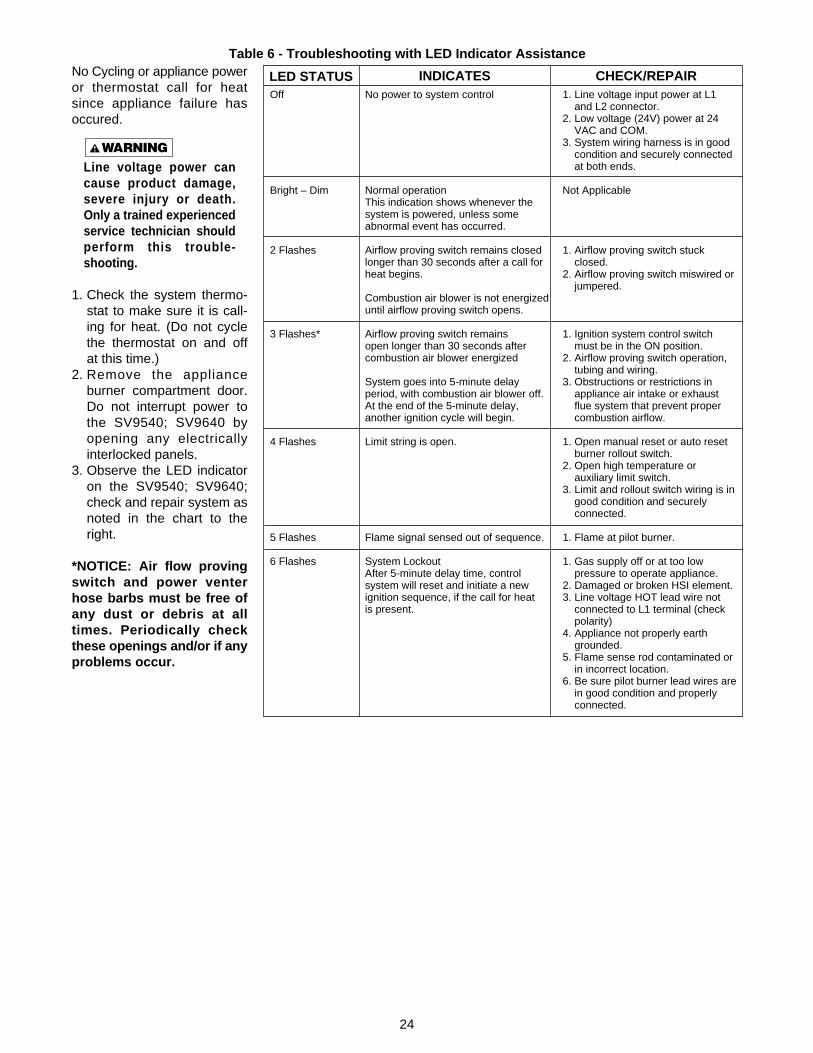
No Cycling or appliance poweror thermostat call for heatsince appliance failure hasoccured.
Line voltage power cancause product damage,severe injury or death.Only a trained experiencedservice technician shouldperform this trouble-shooting.
1. Check the system thermo-stat to make sure it is call-ing for heat. (Do not cyclethe thermostat on and offat this time.)
2. Remove the applianceburner compartment door.Do not interrupt power tothe SV9540; SV9640 byopening any electricallyinterlocked panels.
3. Observe the LED indicatoron the SV9540; SV9640;check and repair system asnoted in the chart to theright.
*NOTICE: Air flow provingswitch and power venterhose barbs must be free ofany dust or debris at alltimes. Periodically checkthese openings and/or if anyproblems occur.
Table 6 - Troubleshooting with LED Indicator Assistance
1. Line voltage input power at L1and L2 connector.
2. Low voltage (24V) power at 24VAC and COM.
3. System wiring harness is in goodcondition and securely connectedat both ends.
Not Applicable
1. Airflow proving switch stuckclosed.
2. Airflow proving switch miswired orjumpered.
1. Ignition system control switchmust be in the ON position.
2. Airflow proving switch operation,tubing and wiring.
3. Obstructions or restrictions inappliance air intake or exhaustflue system that prevent propercombustion airflow.
1. Open manual reset or auto resetburner rollout switch.
2. Open high temperature orauxiliary limit switch.
3. Limit and rollout switch wiring is ingood condition and securelyconnected.
1. Flame at pilot burner.
1. Gas supply off or at too lowpressure to operate appliance.
2. Damaged or broken HSI element.3. Line voltage HOT lead wire not
connected to L1 terminal (checkpolarity)
4. Appliance not properly earthgrounded.
5. Flame sense rod contaminated orin incorrect location.
6. Be sure pilot burner lead wires arein good condition and properlyconnected.
No power to system control
Normal operationThis indication shows whenever thesystem is powered, unless someabnormal event has occurred.
Airflow proving switch remains closedlonger than 30 seconds after a call forheat begins.
Combustion air blower is not energizeduntil airflow proving switch opens.
Airflow proving switch remainsopen longer than 30 seconds aftercombustion air blower energized
System goes into 5-minute delayperiod, with combustion air blower off.At the end of the 5-minute delay,another ignition cycle will begin.
Limit string is open.
Flame signal sensed out of sequence.
System LockoutAfter 5-minute delay time, controlsystem will reset and initiate a newignition sequence, if the call for heatis present.
LED STATUS INDICATES CHECK/REPAIROff
Bright – Dim
2 Flashes
3 Flashes*
4 Flashes
5 Flashes
6 Flashes
25
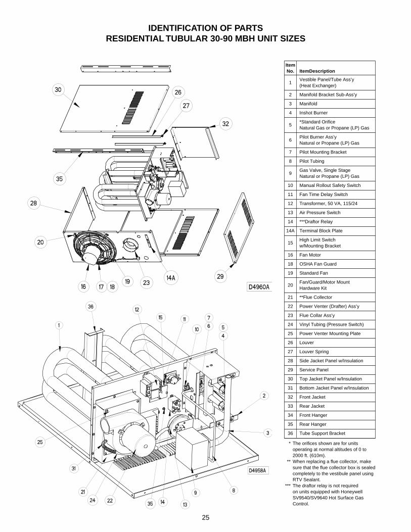
IDENTIFICATION OF PARTSRESIDENTIAL TUBULAR 30-90 MBH UNIT SIZES
1Vestible Panel/Tube Ass’y(Heat Exchanger)
2 Manifold Bracket Sub-Ass’y
3 Manifold
4 Inshot Burner
5*Standard OrificeNatural Gas or Propane (LP) Gas
6Pilot Burner Ass’yNatural or Propane (LP) Gas
7 Pilot Mounting Bracket
8 Pilot Tubing
9Gas Valve, Single StageNatural or Propane (LP) Gas
10 Manual Rollout Safety Switch
11 Fan Time Delay Switch
12 Transformer, 50 VA, 115/24
13 Air Pressure Switch
14 ***Draftor Relay
14A Terminal Block Plate
15High Limit Switchw/Mounting Bracket
16 Fan Motor
18 OSHA Fan Guard
19 Standard Fan
20Fan/Guard/Motor MountHardware Kit
21 **Flue Collector
22 Power Venter (Drafter) Ass’y
23 Flue Collar Ass’y
24 Vinyl Tubing (Pressure Switch)
25 Power Venter Mounting Plate
26 Louver
27 Louver Spring
28 Side Jacket Panel w/Insulation
29 Service Panel
30 Top Jacket Panel w/Insulation
31 Bottom Jacket Panel w/Insulation
32 Front Jacket
33 Rear Jacket
34 Front Hanger
35 Rear Hanger
36 Tube Support Bracket
ItemNo. ItemDescription
*** The orifices shown are for unitsoperating at normal altitudes of 0 to2000 ft. (610m).
*** When replacing a flue collector, makesure that the flue collector box is sealedcompletely to the vestibule panel usingRTV Sealant.
*** The draftor relay is not requiredon units equipped with HoneywellSV9540/SV9640 Hot Surface GasControl.
26
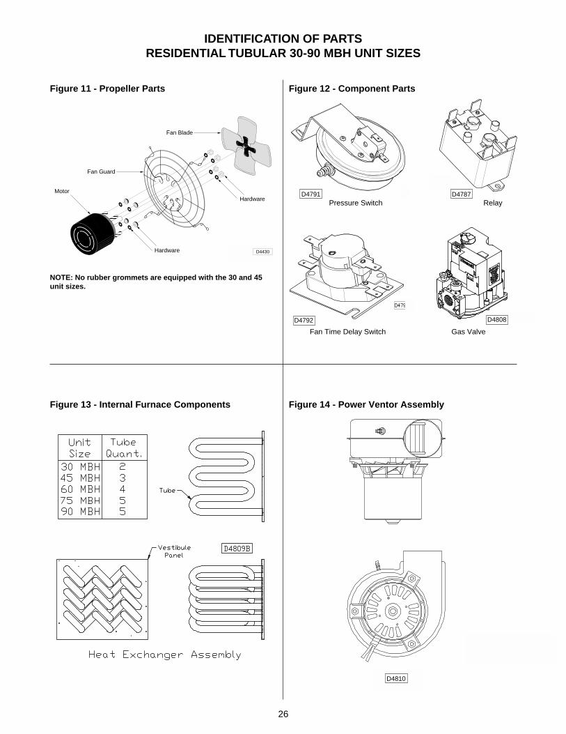
IDENTIFICATION OF PARTSRESIDENTIAL TUBULAR 30-90 MBH UNIT SIZES
Figure 13 - Internal Furnace Components
Figure 11 - Propeller Parts Figure 12 - Component Parts
Figure 14 - Power Ventor Assembly
D4787
D4808D4792
D4791
D4810
NOTE: No rubber grommets are equipped with the 30 and 45unit sizes.
Pressure Switch Relay
Fan Time Delay Switch Gas Valve
D4430
Fan Guard
Fan Blade
Hardware
Hardware
Motor
27
HOW TO ORDER REPLACEMENT PARTS
Please send the following information to your local representative: if further assistance is needed, contact themanufacturer's customer service department.•Model Number•Serial Number (if any)•Part Description and Number as shown in Replacement parts Catalog
LIMITED WARRANTYResidential Power Vented Tubular Propeller Unit Heaters
1. The "Manufacturer" warrants to the original owner at original installation site that the above model Gas-FiredHeater ("the Product") will be free from defects in material or workmanship for (1) year from the date ofshipment from the factory, or one and one-half (1-1/2) years from the date of manufacture, whichever occursfirst. The Manufacturer further warrants that the complete heat exchanger, flue collector and burners be freefrom defects in material or workmanship for a period of ten (10) years from the date of manufacture. If uponexamination by the Manufacturer the Product is shown to have a defect in material or workmanship during thewarranty period, the manufacturer will repair or replace, at its option, that part of the Product which is shownto be defective.
2. This limited warranty does not apply:a. if the product has been subjected to misuse or neglect, has been accidentally or intentionally damaged,
has not been installed, maintained, or operated in accordance with furnished written instructions, or hasbeen altered or modified in any way by any unauthorized person.
b. to any expenses, including labor or material, incurred during removal or reinstallation of the Productc. to any damage due to corrosion by chemicals, including halogenated hydrocarbons, precipitated in the aird. to any workmanship of the installer of the Product
3. This limited warranty is conditional upon:a. advising the installing contractor, who in turn notify the distributor or manufacturerb. shipment to the Manufacturer of that part of the Product thought to be defective. Goods can only be
returned with prior written approval of the Manufacturer. All returns must be freight prepaid.c. determination in the reasonable opinion of the Manufacturer that there exists a defect in material or
workmanship
4. Repair or replacement of any part under this Limited Warranty shall not extend the duration of the warrantywith respect to such repaired or replaced part beyond the stated warranty period.
5. THIS LIMITED WARRANTY IS IN LIEU OF ALL WARRANTIES, EITHER EXPRESS OR IMPLIED, ANDALL SUCH OTHER WARRANTIES, INCLUDING WITHOUT LIMITATION IMPLIED WARRANTIES OFMERCHANTABILITY OR FITNESS FOR A PARTICULAR PURPOSE, ARE HEREBY DISCLAIMED ANDEXCLUDED FROM THIS LIMITED WARRANTY. IN NO EVENT SHALL THE MANUFACTURER BE LIABLEIN ANY WAY FOR ANY CONSEQUENTIAL, SPECIAL, OR INCIDENTAL DAMAGES OF ANY NATUREWHATSOEVER, OR FOR ANY AMOUNTS IN EXCESS OF THE SELLING PRICE OF THE PRODUCT ORANY PARTS THEREOF FOUND TO BE DEFECTIVE. THIS LIMITED WARRANTY GIVES THE ORIGINALOWNER OF THE PRODUCT SPECIFIC LEGAL RIGHTS. YOU MAY ALSO HAVE OTHER RIGHTS WHICHMAY VARY BY JURISDICTION.
In the interest of product improvement, we reserve the right to make changes without notice.
28
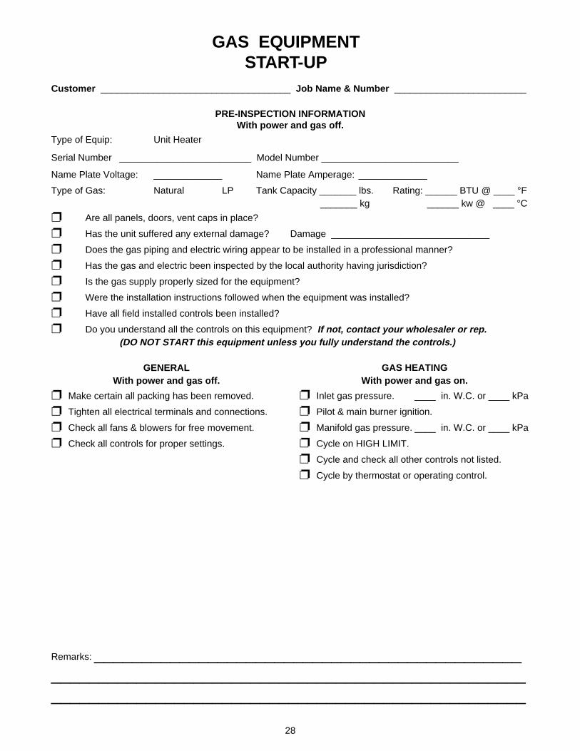
Customer ____________________________________ Job Name & Number _________________________
PRE-INSPECTION INFORMATIONWith power and gas off.
Type of Equip: Unit Heater
Serial Number _________________________ Model Number __________________________
Name Plate Voltage: _____________ Name Plate Amperage: _____________
Type of Gas: Natural LP Tank Capacity _______ lbs. Rating: ______ BTU @ ____ °F _______ kg ______ kw @ ____ °C
❐ Are all panels, doors, vent caps in place?
❐ Has the unit suffered any external damage? Damage ______________________________
❐ Does the gas piping and electric wiring appear to be installed in a professional manner?
❐ Has the gas and electric been inspected by the local authority having jurisdiction?
❐ Is the gas supply properly sized for the equipment?
❐ Were the installation instructions followed when the equipment was installed?
❐ Have all field installed controls been installed?
❐ Do you understand all the controls on this equipment? If not, contact your wholesaler or rep.(DO NOT START this equipment unless you fully understand the controls.)
GAS EQUIPMENTSTART-UP
GENERALWith power and gas off.
❐ Make certain all packing has been removed.
❐ Tighten all electrical terminals and connections.
❐ Check all fans & blowers for free movement.
❐ Check all controls for proper settings.
BLOWERWith power on and gas off.
❐ Check voltage L1 _____ L2 _____ L3 _____
❐ Check rotation of main blower.
❐ Check motor amps L1 _____ L2 _____ L3 _____
❐ Blower RPM _____________
❐ Check air filters. (Record quantity & size.)
Remarks: _________________________________________________________________________________________________________________________________________________
GAS HEATINGWith power and gas on.
❐ Inlet gas pressure. ____ in. W.C. or ____ kPa
❐ Pilot & main burner ignition.
❐ Manifold gas pressure. ____ in. W.C. or ____ kPa
❐ Cycle on HIGH LIMIT.
❐ Cycle and check all other controls not listed.
❐ Cycle by thermostat or operating control.