s model ice beverage & quietqube ice machines
TRANSCRIPT

Read this instruction before operating this equipmentAmerica’s #1 Selling Ice Machine
Original Document
S Model Ice Beverage & QuietQube Ice MachinesInstallation Operation and Maintenance Manual
Engineered for Ease
Part Number 000006505 Rev02 12/19

Table of Contents
Section 1 General Information
Model Numbers . . . . . . . . . . . . . . . . . . . . . . . . . . . . . . . . . . . . . . . . . . . . . . . . . . . . . 4Ice Deflector . . . . . . . . . . . . . . . . . . . . . . . . . . . . . . . . . . . . . . . . . . . . . . . . . . . . 4Bin Installation . . . . . . . . . . . . . . . . . . . . . . . . . . . . . . . . . . . . . . . . . . . . . . . . . . 4Dispenser Installation . . . . . . . . . . . . . . . . . . . . . . . . . . . . . . . . . . . . . . . . . . . . 4
Section 2 Installation
Location Requirements . . . . . . . . . . . . . . . . . . . . . . . . . . . . . . . . . . . . . . . . . . . . . . 5Minimum/Maximum Temperatures . . . . . . . . . . . . . . . . . . . . . . . . . . . . . . . . . . . . . 5
Ice Machine Clearance Requirements . . . . . . . . . . . . . . . . . . . . . . . . . . . . . . . . 5Condensing Unit Clearance Requirements . . . . . . . . . . . . . . . . . . . . . . . . . . . . 5
Installation Requirements . . . . . . . . . . . . . . . . . . . . . . . . . . . . . . . . . . . . . . . . . . . . 6Water Supply and Drains . . . . . . . . . . . . . . . . . . . . . . . . . . . . . . . . . . . . . . . . . . . . . 6
Potable Water Requirements . . . . . . . . . . . . . . . . . . . . . . . . . . . . . . . . . . . . . . . 6Drain Connections . . . . . . . . . . . . . . . . . . . . . . . . . . . . . . . . . . . . . . . . . . . . . . . 6Water Supply and Drain Line Sizing/Connections . . . . . . . . . . . . . . . . . . . . . . . 7Cooling Tower Applications . . . . . . . . . . . . . . . . . . . . . . . . . . . . . . . . . . . . . . . . 7
Electrical Service . . . . . . . . . . . . . . . . . . . . . . . . . . . . . . . . . . . . . . . . . . . . . . . . . . . 8General . . . . . . . . . . . . . . . . . . . . . . . . . . . . . . . . . . . . . . . . . . . . . . . . . . . . . . . 8Fuse/Circuit Breaker . . . . . . . . . . . . . . . . . . . . . . . . . . . . . . . . . . . . . . . . . . . . . 8Minimum Circuit Ampacity . . . . . . . . . . . . . . . . . . . . . . . . . . . . . . . . . . . . . . . . . 8Ground Fault Circuit Interrupter . . . . . . . . . . . . . . . . . . . . . . . . . . . . . . . . . . . . . 8
Electrical Requirements . . . . . . . . . . . . . . . . . . . . . . . . . . . . . . . . . . . . . . . . . . . . . . 9CVD Condensing Units . . . . . . . . . . . . . . . . . . . . . . . . . . . . . . . . . . . . . . . . . . . 9QuietQube® Ice Machine Head Section . . . . . . . . . . . . . . . . . . . . . . . . . . . . . . 10
Refrigeration System Installation . . . . . . . . . . . . . . . . . . . . . . . . . . . . . . . . . . . . . . 11Refrigeration Line Set Installation . . . . . . . . . . . . . . . . . . . . . . . . . . . . . . . . . . . 12Electronic Bin Thermostat Instructions IB600C/IB800C/IB1000C Only . . . . . . . 15
Section 3 Operation
Ice Making Sequence of Operation . . . . . . . . . . . . . . . . . . . . . . . . . . . . . . . . . . . . . 16Safety limits . . . . . . . . . . . . . . . . . . . . . . . . . . . . . . . . . . . . . . . . . . . . . . . . . . . . 16
Operational Checks . . . . . . . . . . . . . . . . . . . . . . . . . . . . . . . . . . . . . . . . . . . . . . . . . 17Ice Thickness Check . . . . . . . . . . . . . . . . . . . . . . . . . . . . . . . . . . . . . . . . . . . . . 17
2 Part Number 000006505 Rev02 12/19

Table of Contents (continued)
Section 4 Maintenance
Cleaning and Sanitizing . . . . . . . . . . . . . . . . . . . . . . . . . . . . . . . . . . . . . . . . . . . . . 18Cleaning/Sanitizing Procedure Differences . . . . . . . . . . . . . . . . . . . . . . . . . . . . 18Exterior Cleaning . . . . . . . . . . . . . . . . . . . . . . . . . . . . . . . . . . . . . . . . . . . . . . . . 18
Cleaning / Sanitizing Procedure . . . . . . . . . . . . . . . . . . . . . . . . . . . . . . . . . . . . . . . 19Cleaning Procedure . . . . . . . . . . . . . . . . . . . . . . . . . . . . . . . . . . . . . . . . . . . . . 19Sanitizing Procedure . . . . . . . . . . . . . . . . . . . . . . . . . . . . . . . . . . . . . . . . . . . . . 20
Procedure to Clean Heavily Scaled Ice Machines . . . . . . . . . . . . . . . . . . . . . . . . 21Cleaning Procedure . . . . . . . . . . . . . . . . . . . . . . . . . . . . . . . . . . . . . . . . . . . . . 21Sanitizing Procedure . . . . . . . . . . . . . . . . . . . . . . . . . . . . . . . . . . . . . . . . . . . . . 22Parts Removal for Cleaning/Sanitizing . . . . . . . . . . . . . . . . . . . . . . . . . . . . . . . 24
Door Removal . . . . . . . . . . . . . . . . . . . . . . . . . . . . . . . . . . . . . . . . . . . . . . . . . . . . . . 28Exterior Cleaning . . . . . . . . . . . . . . . . . . . . . . . . . . . . . . . . . . . . . . . . . . . . . . . . . . . 28Cleaning the Condenser . . . . . . . . . . . . . . . . . . . . . . . . . . . . . . . . . . . . . . . . . . . . . 28Removal from Service/Winterization . . . . . . . . . . . . . . . . . . . . . . . . . . . . . . . . . . . 28
Section 5 Customer Support
Before Calling for Service Checklist . . . . . . . . . . . . . . . . . . . . . . . . . . . . . . . . . . . 29Safety Limit Feature . . . . . . . . . . . . . . . . . . . . . . . . . . . . . . . . . . . . . . . . . . . . . 30
Commercial Ice Machine Warranty . . . . . . . . . . . . . . . . . . . . . . . . . . . . . . . . . . . . 31Residential Ice Machine Limited Warranty . . . . . . . . . . . . . . . . . . . . . . . . . . . . . . 32
Part Number 000006505 Rev02 12/19 3

Section 1General Information
Model NumbersThis manual covers the following models:
.
ICE DEFLECTORAn ice deflector is required when the ice machine is installed on a bin. An ice deflector is not required when the ice machine is installed on a dispenser.
BIN INSTALLATION• All ice machines installed on a bin require an ice
deflector.• Manitowoc bins have a deflector installed and require
no modifications when used with a forward facingevaporator.
• Ice machines with multiple evaporators require adeflector kit.
DISPENSER INSTALLATION• Ice Beverage ice machines require an adapter for all
installations.• No adapter is needed for machines that match the
size of the dispenser unless required by thedispenser manufacturer.
• No deflector is required unless specified by thedispenser manufacturer.
• A bin thermostat to control ice level is recommended.
Ice Machine Head Section CVD® Condensing UnitSD0682C - SY0684CIB0684YC - IB0682DC
CVD0675 - CVD0685
SD0872C - SY0874CIB0824YC - IB0822DC
CVD0885
SD1072C - SY1074C CVD1085IB1024YC - IB1022DC CVD1185SD1272C - SY1274C CVD1285SD1472C - SY1474C CVD1485 - CVD1486SD1872C - SY1874C CVD1885 SD2172C - SY2174C CVD2075 - CVD2085 SD3072C - SY3074C CVD3085
SDF3000C - SYF3000C CVDF3000
! WarningDo not operate equipment that has been misused,abused, neglected, damaged, or altered/modifiedfrom that of original manufactured specifications.This appliance is not intended for use by persons(including children) with reduced physical, sensoryor mental capabilities, or lack of experience andknowledge, unless they have been givensupervision concerning use of the appliance by aperson responsible for their safety.
! WarningS1470C/S1870C/S2170C ice machines are notapproved for use on Manitowoc B570 bins.
! WarningS3000C/SF3000C ice machines are not approvedfor use on Manitowoc B970 or D970 bins.
! Warning30” large capacity bins must be attached to the wallwith the bracket provided with the bin.
! WarningManitowoc ice machines require a deflector wheninstalled on an ice storage bin.Prior to using a non-Manitowoc ice storage systemwith Manitowoc ice machines, contact themanufacturer to assure their ice deflector iscompatible with Manitowoc ice machines.
! WarningChildren must be supervised to ensure they do notplay with the ice machine, bin or dispenser.
Part Number 000006505 Rev02 12/19 4

Section 2Installation
Location RequirementsThe location selected for the ice machine must meet the following criteria. If any of these criteria are not met, select another location.• The location must be free of airborne and other
contaminants.• The location must not be near heat-generating
equipment or in direct sunlight.• The location must be capable of supporting the
weight of the ice machine and a full bin of ice.• The location must allow enough clearance for water,
drain and electrical connections in the rear of the ice machine.
• The location must not obstruct airflow through or around the ice machine.
• The location must not allow exhaust fan heat and/or grease to enter the condenser.
• The location must allow electrical, water, drain and refrigeration tubing to enter the ice machine from the back.
• Local water conditions may require treatment of the water to inhibit scale formation, filter sediment, and remove chlorine odor and taste.
These ice machines are intended for use in household and similar applications such as:• Staff kitchen areas in shops, offices and other work
environments.• Clients in hotels, motels, farmhouses, bed and
breakfast and other residential type environments.• Catering and similar non-retail applications.
MINIMUM/MAXIMUM TEMPERATURES
ICE MACHINE CLEARANCE REQUIREMENTS
CONDENSING UNIT CLEARANCE REQUIREMENTS
! WarningPERSONAL INJURY POTENTIAL
Remove all ice machine panels before lifting andinstalling.
Model Minimum Air Temperature
Maximum Air Temperature
All Ice Machine Head Sections
35°F2°C
110°F 43°C
CVD0675 - CVD0685 CVD1185 - CVD2075 CVD2085 - CVD3085
CVDF3000
-20°F-29°C
120°F 49°C
CVD0885 - CVD1085 CVD1285 - CVD1485
CVD1885
-20°F-29°C
130°F 54°C
CVD148635°F2°C
110°F 43°C
Model Top Back SidesS0600C - S0800C S1000C - S1200C S1470C - S1870C
S2170C
5"13 cm
*3" - 5"*8 - 13 cm
5"13 cm
IB0600C - IB0800C IB1000C
2"5 cm
5"13 cm
8"20 cm
S3000C - SF3000C8"
20 cm24"
61 cm**8”
**20 cm* Routing utilities out top - Routing utilities out back
** 24" (61 cm) is recommended on all sides
Model Top/Sides Back FrontCVD0675 - CVD0685 CVD0885 - CVD1085 CVD1185 - CVD1285CVD1885 - CVD2085
*6”*15 cm
48"122 cm
48"122 cm
CVD1285 - CVD1485*6”
*15 cm48"
122 cm24"
61 cm
CVD1486*5”
*13 cm12"
30 cm12"
30 cm
CVD3085 - CVDF3000*6”
*15 cm24"
122 cm24"
122 cm* 24" (61 cm) is recommended on top/sides
Part Number 000006505 Rev02 12/19 5

Installation Section 2
Installation Requirements• The ice machine top panel can be trimmed with an
aviator snips to allow the line set, water line and electrical connections to exit the top. Only cut out what is needed, the back panel recess sheet metal must support the top panel.
• The ice machine and bin must be level.• Vent the ice machine and bin drains separately.• Bin drain termination must have an air gap.• The water inlet and electrical connection must
contain a service loop to allow future access.• The drain line must contain a union or other suitable
means of disconnection at the ice machine.• The ice machine and bin must be sanitized after
installation.• Routine adjustments and maintenance procedures
outlined in this manual are not covered by the warranty.
Water Supply and DrainsPOTABLE WATER REQUIREMENTSLocal water conditions may require treatment of the water to inhibit scale formation, filter sediment, and remove chlorine odor and taste.
Follow these guidelines to install water inlet lines:• Plumbing must conform to local codes.• Do not connect the ice machine to a hot water
supply. Be sure all hot water restrictors installed for other equipment are working. (Check valves on sink faucets, dishwashers, etc.)
• If water pressure exceeds the maximum recommended pressure of 80 psig (552 kPa), obtain a water pressure regulator from your Manitowoc distributor.
• Install a water shut-off valve and union for potable water and water cooled condenser lines.
• Insulate water inlet lines to prevent condensation.
DRAIN CONNECTIONS• Drain lines must have a 1.5 inch drop per 5 feet of
run (2.5 cm per meter), and must not create traps.• The floor drain must be large enough to
accommodate drainage from all drains.• Run separate bin and ice machine drain lines.
Insulate them to prevent condensation.• Vent the bin and ice machine drain to the
atmosphere. The ice machine drain requires an 18" vent. Do not vent the condenser drain on water-cooled models.
• Drains must have a union or other suitable means to allow in place disconnection from the ice machine when servicing is required.
• Base drain - Use 1/2” CPVC tubing and silicone sealant to connect to this optional drain.
• S3000C/SF3000C requires base drain connection (1" FPT).
! WarningConnect to a potable water supply only.
6 Part Number 000006505 Rev02 12/19
Section 2 Installation
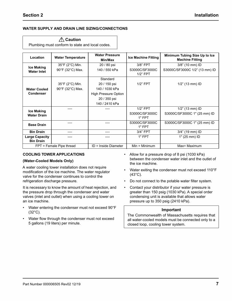
WATER SUPPLY AND DRAIN LINE SIZING/CONNECTIONS
COOLING TOWER APPLICATIONS (Water-Cooled Models Only)A water cooling tower installation does not require modification of the ice machine. The water regulator valve for the condenser continues to control the refrigeration discharge pressure.It is necessary to know the amount of heat rejection, and the pressure drop through the condenser and water valves (inlet and outlet) when using a cooling tower on an ice machine.• Water entering the condenser must not exceed 90°F
(32°C).• Water flow through the condenser must not exceed
5 gallons (19 liters) per minute.
• Allow for a pressure drop of 8 psi (1030 kPa) between the condenser water inlet and the outlet of the ice machine.
• Water exiting the condenser must not exceed 110°F (43°C).
• Do not connect to the potable water filter system.• Contact your distributor if your water pressure is
greater than 150 psig (1030 kPa). A special order condensing unit is available that allows water pressure up to 350 psig (2410 kPa).
! CautionPlumbing must conform to state and local codes.
Location Water TemperatureWater Pressure
Min/MaxIce Machine Fitting Minimum Tubing Size Up to Ice
Machine Fitting
Ice Making Water Inlet
35°F (2°C) Min.90°F (32°C) Max.
20 / 80 psi140 / 550 kPa
3/8” FPTS3000C/SF3000C
1/2” FPT
3/8” (10 mm) IDS3000C/SF3000C 1/2” (13 mm) ID
Water Cooled Condenser
35°F (2°C) Min.90°F (32°C) Max.
Standard20 / 150 psi
140 / 1030 kPaHigh Pressure Option
20 / 350 psi 140 / 2410 kPa
1/2” FPT 1/2” (13 mm) ID
Ice Making Water Drain
---- ---- 1/2” FPTS3000C/SF3000C
1" FPT
1/2” (13 mm) IDS3000C/SF3000C 1" (25 mm) ID
Base Drain ---- ---- S3000C/SF3000C1" FPT
S3000C/SF3000C 1" (25 mm) ID
Bin Drain ---- ---- 3/4” FPT 3/4” (19 mm) IDLarge Capacity
Bin Drain---- ---- 1" FPT 1" (25 mm) ID
FPT = Female Pipe thread ID = Inside Diameter Min = Minimum Max= Maximum
ImportantThe Commonwealth of Massachusetts requires thatall water-cooled models must be connected only to aclosed loop, cooling tower system.
Part Number 000006505 Rev02 12/19 7

Installation Section 2
Electrical ServiceGENERAL
All electrical work, including wire routing and grounding, must conform to local, state and national electrical codes. The following precautions must be observed:• The ice machine must be grounded.• A separate fuse/circuit breaker must be provided for
each condensing unit.• A qualified electrician must determine proper wire
size dependent upon location, materials used and length of run (minimum circuit ampacity can be used to help select the wire size).
• The maximum allowable voltage variation is +/-10 of the rated voltage at compressor start-up (when the electrical load is highest).
• Check all green ground screws in the control box and verify they are tight before starting the ice machine.
• Verify polarity is correct. Incorrect polarity can lead to erratic ice machine operation and a safety issue. This is especially critical on 230 volt / 50 cycle ice machines.
FUSE/CIRCUIT BREAKERThe ice machine head section and condensing unit are wired independently of each other.A dedicated circuit and a separate fuse/circuit breaker are required for each ice machine and condensing unit.
MINIMUM CIRCUIT AMPACITYThe minimum circuit ampacity is used to help select the wire size of the electrical supply. (Minimum circuit ampacity is not the ice machine’s running amp load.)The wire size (or gauge) is also dependent upon location, materials used, length of run, etc., so it must be determined by a qualified electrician. Manitowoc Ice requires minimum #8 AWG for S2170C condensing unit applications.
GROUND FAULT CIRCUIT INTERRUPTERWe do not recommend the use of a GFCI/GFI circuit protection with our equipment. If a GFCI/GFI is required by code use a GFCI/GFI breaker rather than outlet which is more prone to intermittent nuisance trips than panel circuit breakers.
! WarningAll wiring must conform to local, state and nationalcodes.
! WarningThe ice machine and condensing unit must begrounded in accordance with national and localelectrical codes.
ImportantObserve correct polarity of incoming line voltage.
For United Kingdom OnlyAs the colors of the wires in the mains lead of the appliance may not correspond with the colored markings identifying the terminals in your plug, proceed as follows:• The wire which is colored green and yellow must be
connected to the terminal in the plug which is marked with the letter E or by the earth ground symbol or colored green or green and yellow.
• The wire colored blue must be connected to the terminal which is marked with the letter N or colored black.
• The wire colored brown must be connected to the terminal which is marked with the letter L or colored red.
8 Part Number 000006505 Rev02 12/19
Section 2 Installation
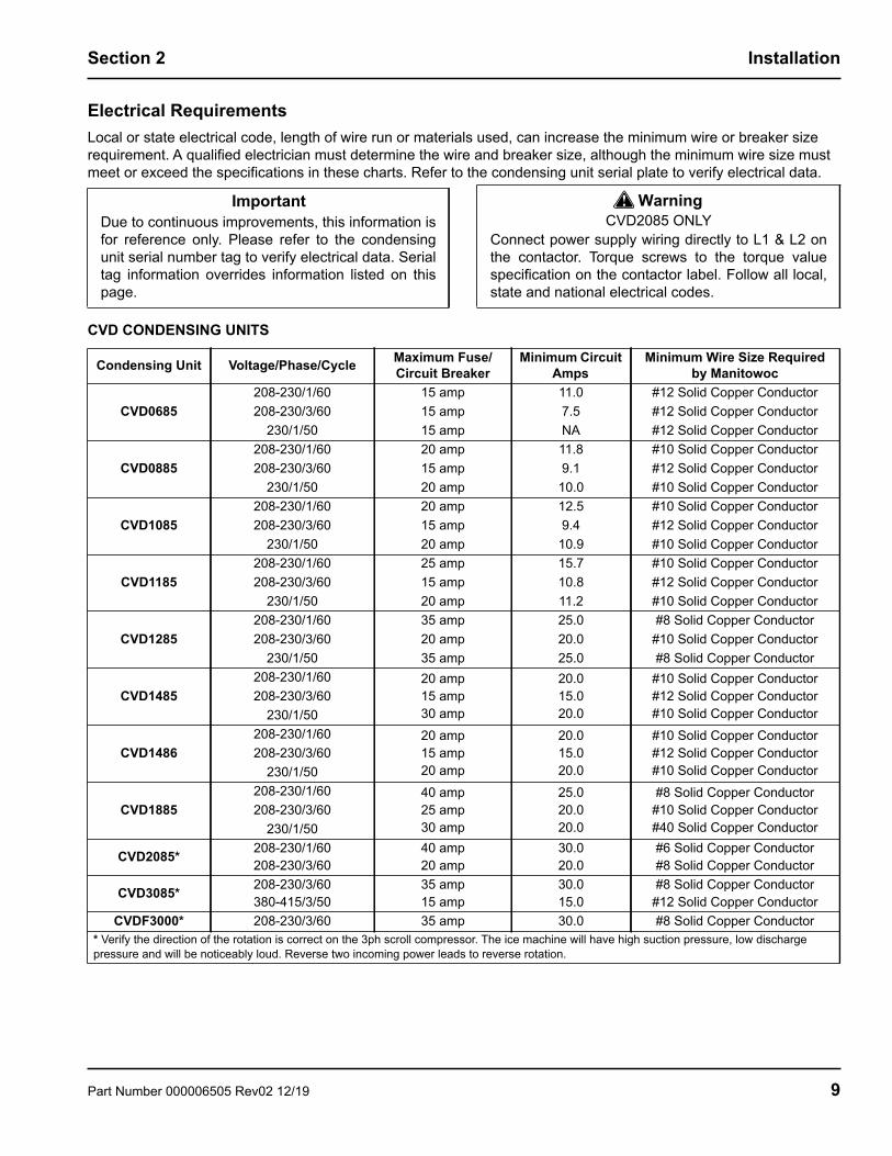
Electrical RequirementsLocal or state electrical code, length of wire run or materials used, can increase the minimum wire or breaker size requirement. A qualified electrician must determine the wire and breaker size, although the minimum wire size must meet or exceed the specifications in these charts. Refer to the condensing unit serial plate to verify electrical data.
CVD CONDENSING UNITS
ImportantDue to continuous improvements, this information isfor reference only. Please refer to the condensingunit serial number tag to verify electrical data. Serialtag information overrides information listed on thispage.
! WarningCVD2085 ONLY
Connect power supply wiring directly to L1 & L2 onthe contactor. Torque screws to the torque valuespecification on the contactor label. Follow all local,state and national electrical codes.
Condensing Unit Voltage/Phase/Cycle Maximum Fuse/Circuit Breaker
Minimum Circuit Amps
Minimum Wire Size Required by Manitowoc
CVD0685208-230/1/60 15 amp 11.0 #12 Solid Copper Conductor208-230/3/60 15 amp 7.5 #12 Solid Copper Conductor
230/1/50 15 amp NA #12 Solid Copper Conductor
CVD0885208-230/1/60 20 amp 11.8 #10 Solid Copper Conductor208-230/3/60 15 amp 9.1 #12 Solid Copper Conductor
230/1/50 20 amp 10.0 #10 Solid Copper Conductor
CVD1085208-230/1/60 20 amp 12.5 #10 Solid Copper Conductor208-230/3/60 15 amp 9.4 #12 Solid Copper Conductor
230/1/50 20 amp 10.9 #10 Solid Copper Conductor
CVD1185208-230/1/60 25 amp 15.7 #10 Solid Copper Conductor208-230/3/60 15 amp 10.8 #12 Solid Copper Conductor
230/1/50 20 amp 11.2 #10 Solid Copper Conductor
CVD1285208-230/1/60 35 amp 25.0 #8 Solid Copper Conductor208-230/3/60 20 amp 20.0 #10 Solid Copper Conductor
230/1/50 35 amp 25.0 #8 Solid Copper Conductor
CVD1485208-230/1/60 20 amp
15 amp30 amp
20.015.020.0
#10 Solid Copper Conductor#12 Solid Copper Conductor#10 Solid Copper Conductor
208-230/3/60230/1/50
CVD1486208-230/1/60 20 amp
15 amp20 amp
20.015.020.0
#10 Solid Copper Conductor#12 Solid Copper Conductor#10 Solid Copper Conductor
208-230/3/60230/1/50
CVD1885208-230/1/60 40 amp
25 amp30 amp
25.020.020.0
#8 Solid Copper Conductor#10 Solid Copper Conductor#40 Solid Copper Conductor
208-230/3/60230/1/50
CVD2085* 208-230/1/60208-230/3/60
40 amp20 amp
30.020.0
#6 Solid Copper Conductor#8 Solid Copper Conductor
CVD3085* 208-230/3/60380-415/3/50
35 amp15 amp
30.015.0
#8 Solid Copper Conductor#12 Solid Copper Conductor
CVDF3000* 208-230/3/60 35 amp 30.0 #8 Solid Copper Conductor* Verify the direction of the rotation is correct on the 3ph scroll compressor. The ice machine will have high suction pressure, low discharge pressure and will be noticeably loud. Reverse two incoming power leads to reverse rotation.
Part Number 000006505 Rev02 12/19 9
Installation Section 2
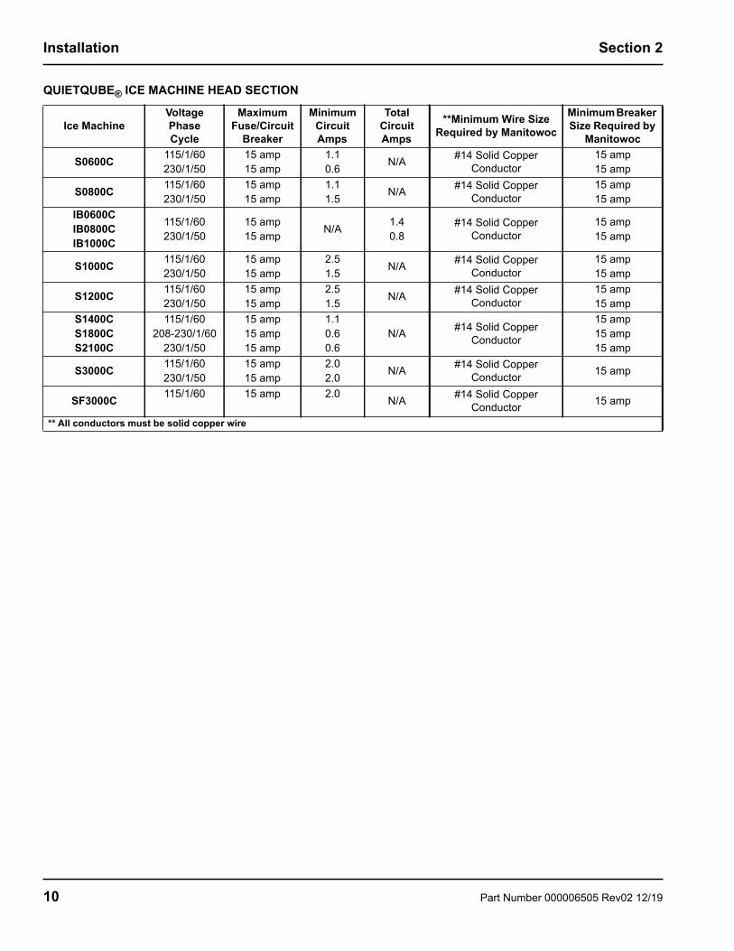
QUIETQUBE® ICE MACHINE HEAD SECTION
Ice MachineVoltagePhaseCycle
Maximum Fuse/Circuit
Breaker
Minimum Circuit Amps
Total Circuit Amps
**Minimum Wire Size Required by Manitowoc
Minimum Breaker Size Required by
Manitowoc
S0600C 115/1/60230/1/50
15 amp15 amp
1.10.6 N/A #14 Solid Copper
Conductor15 amp15 amp
S0800C 115/1/60230/1/50
15 amp15 amp
1.11.5 N/A #14 Solid Copper
Conductor15 amp15 amp
IB0600CIB0800CIB1000C
115/1/60230/1/50
15 amp15 amp N/A 1.4
0.8#14 Solid Copper
Conductor15 amp15 amp
S1000C 115/1/60230/1/50
15 amp15 amp
2.51.5 N/A #14 Solid Copper
Conductor15 amp15 amp
S1200C 115/1/60230/1/50
15 amp15 amp
2.51.5 N/A #14 Solid Copper
Conductor15 amp15 amp
S1400CS1800CS2100C
115/1/60208-230/1/60
230/1/50
15 amp15 amp15 amp
1.10.60.6
N/A #14 Solid Copper Conductor
15 amp15 amp15 amp
S3000C 115/1/60230/1/50
15 amp15 amp
2.02.0 N/A #14 Solid Copper
Conductor 15 amp
SF3000C 115/1/60 15 amp 2.0 N/A #14 Solid Copper Conductor 15 amp
** All conductors must be solid copper wire
10 Part Number 000006505 Rev02 12/19

Section 2 Installation
Refrigeration System Installation
Ice Machine Refrigerant AmountsICE MACHINE HEAD SECTIONEach ice machine head section ships from the factory with a R-404A refrigerant charge appropriate for the entire system operation. The serial tag on the ice machine indicates the refrigerant charge. The refrigerant charge is sufficient to operate the ice machine at all ambients with lineset lengths up to 100 feet (30 m).
QuietQube®Ice Machine
Remote Single Circuit
CondenserLine Set*
S0600CIB600C CVD685
RC-21RC-31RC-51
S0800CIB800C CVD885
S1000C CVD1085IB1000C CVD1185
RC-20RC-30RC-50
S1200C CVD1285
S1470C CVD1485CVD1486
S1870C CVD1885
S2170C CVD2085RC-23RC-33RC-53
S3000CSF3000C
CVD3085CVDF3000
RC-24RC-34RC-54
*Line Set Suction Line
Liquid Line
Minimum Insulation Thickness
RC 21/31/51 5/8 inch(16 mm)
3/8 inch(10 mm)
1/2” (13mm) Suction Line
1/4” (7mm) Liquid Line
RC 20/30/50 3/4 inch(19 mm)
1/2 inch(13 mm)
1/2”(13mm) Suction Line
1/4” (7mm) Liquid Line
RC 23/33/53 3/4 inch(19 mm)
5/8 inch(16 mm)
1/2”(13mm) Suction Line
1/4” (7mm) Liquid Line
RC 24/34/54Two Lines -
3/4 inch(19 mm)
One Line - 5/8 inch(16 mm)
3/4”(19mm) Suction Line
1/4” (7mm) Liquid Line
ImportantManitowoc remote systems are only approved andwarranted as a complete new package. Warrantyon the refrigeration system will be void if a new icemachine head section is connected to pre-existing(used) tubing or condensing units or vice versa.
! CautionThe refrigeration system warranty will not apply ifthe Manitowoc Ice Machine and Manitowoc CVDCondensing Unit are not installed according tospecifications. This warranty also will not apply ifthe refrigeration system is modified with acondenser, heat reclaim device, or other parts orassemblies not manufactured by Manitowoc.
! WarningPotential Personal Injury Situation
The ice machine head section contains therefrigerant charge. Installation and brazing of theline sets must be performed by a properly trainedand EPA certified refrigeration technician aware ofthe dangers of dealing with refrigerant chargedequipment.
! WarningInstallation of a QuietQube® Condensing Unit mayrequire the use of special equipment for placement.Trained and qualified personnel are required forproper rigging and lifting. Holes are provided on thecorners of the condensing unit to allow the use oflifting shackles.
Part Number 000006505 Rev02 12/19 11

Installation Section 2
REFRIGERATION LINE SET INSTALLATIONThe following requirements assure proper oil return.The refrigeration line set installer must be certified/licensed in refrigerant handling and servicing.
Step 1 Lineset Requirements• Maximum lineset length is 100' (30 m).• Maximum rise is 35' (10 m).• Maximum drop is 15' (4.5 m).• A suction line oil trap is required when rise is more
than 20' (6 m).• Maximum lineset exposed on rooftop is 25% of total
line set length.• Only one trap is allowed in the lineset.• Shorten the lineset as required, do not coil lineset.• A qualified person must perform all roof penetrations
.
Manitowoc S-Trap Kit
Step 2 Secure CondenserThrough holes are provided to secure the condenser to a curb, rack, or wooden timber.Step 3 Route Refrigeration TubingProperly route refrigeration tubing between the ice machine head section and the CVD® condensing unit.
The line set can be routed for entry through the top or rear of the ice machine head section.• Top routing requires the cover to be trimmed.• Rear routing may require the use of 90° elbows.
! WarningThe ice machine head section contains refrigerantcharge. The ice machine head section containsrefrigeration valves that must remain closed untilproper installation of the line sets is completed.
! WarningElectrical power to the ice machine head sectionand CVD® condensing unit must be disconnectedbefore proceeding.
35' (10 M) MAX.
DISTANCE100' (30 M)
MAX LINESETLENGTH
Model S-Trap Kit Number Tubing Size
S0600C IB600C S0800C IB800C
S1000CK00172
5/8 inch(15.9 mm)
IB1000C S1200C S1470C S1870C
S2170C S3000C*
SF3000C*
K001663/4 inch
(19.1 mm)
*S3000C/SF3000C - requires two S-Trap kits, one for each suction line.
15' (4.5 M) MAX.
DISTANCE
MORE THAN 20' (6 M) RISES-TRAP KIT REQUIRED
12 Part Number 000006505 Rev02 12/19

Section 2 Installation
Step 4 Connect the line set• Maximum amount of time the refrigeration system
can be exposed to the atmosphere is 15 minutes• Purge line set with dry nitrogen while brazing.• Line set shut off valves on the ice machine must
remain closed and be protected from heat during brazing.
• The condensing unit ships with a 50/50 mixture of nitrogen/helium.
• S3000C/SF3000C has 2 suction lines and requires installation of a tee at the condensing unit.
Step 5 Pressure Test and Evacuate Line Set and CVD Condensing Unit
• Lineset shutoff valves must remain closed until pressure testing and evacuation are complete.
• Schrader valve core removal tools that allow for removal and installation of the valve cores without removing manifold gauge set hoses are recommended to decrease the evacuation time.
• Pressure test @ 150 psi (1000 kPa) for a minimum of 15 minutes.
• Minimum evacuation level is 500 microns.
SUCTION LINE FROM HEAD
SECTION
SUCTION LINE FROM HEAD
SECTION
SUCTION LINE ON CONDENSING UNIT
S3000C/SF3000CTUBING MUST BE CONNECTED TO TEE AS SHOWN
VALVES MUST REMAIN CLOSED AND BE
PROTECTED FROM HEAT WHEN BRAZING
(WRAP WITH WET RAG)
MINIMIZE THE TIME THE REFRIGERATION SYSTEM
IS EXPOSED TO THE ATMOSPHERE (15
MINUTES MAXIMUM)
LIQUID LINE
SUCTION LINE
CONNECT VACUUM PUMP TO LINE SET SHUT OFF VALVES
ALTERNATE CONNECTIONS AT CONDENSING UNIT SCHRADER VALVES
Part Number 000006505 Rev02 12/19 13

Installation Section 2
Step 6 Open Lineset and Receiver ValvesYou will not hear refrigerant flow when the valves are opened. Refrigerant will not flow until the toggle switch is placed in the ice position and the solenoid valve opens.• All valve caps must be reinstalled, tightened and leak
checked to assure no refrigerant leakage exists.• Counterclockwise opens all valves:
A. Refer to chart and open the suction and liquid line shut off valves the correct number of 360° turns.
B. Open the receiver service valve until backseated (two valves on the S3000C/SF3000C).
.
S0600C/S0800C/S1000C/S1200C.
IB0600C/IB0800C/IB1000C
S1470C/S1870C/S2170C
S3000C/SF3000C
Valve Tubing Size Number of Turns To Open3/8” 6
1/2” 5/8” 3/4” 107/8” 14
USE ALLEN WRENCH TO OPEN (TURN COUNTERCLOCKWISE)
LIQUID AND SUCTION LINE SHUT OFF VALVES
USE ALLEN WRENCH TO OPEN (TURN
COUNTERCLOCKWISE) LIQUID AND SUCTION
LINE SHUT OFF VALVES
! CautionAfter opening suction, discharge and receiverservice valves, refrigerant pressure will not bedetected until the toggle switch is placed in the iceposition and the solenoid valves energize.
USE ALLEN WRENCH TO OPEN (TURN
COUNTERCLOCKWISE) LIQUID AND SUCTION
LINE SHUT OFF VALVES
USE ALLEN WRENCH TO OPEN (TURN
COUNTERCLOCKWISE) LIQUID AND SUCTION
LINE SHUT OFF VALVES
14 Part Number 000006505 Rev02 12/19

Section 2 Installation
Step 7 Leak Check The Refrigeration SystemA. Connect power to the ice machine head section -
Do not connect power to the CVD condensing unit.
B. Place the ICE/OFF/CLEAN toggle switch in the ICE position for 60 seconds to equalize pressures, then move to OFF position.
C. Disconnect power to the ice machine head section.
D. Leak check lineset connections, S trap and all factory joints in head section and condensing unit.
E. Connect power to the CVD condensing unit and allow system to pump down.
Step 8 Insulation Requirements• To prevent condensation the entire suction line
including the shut-off valve must be insulated. • All insulation must be airtight and sealed at both
ends.The following insulation requirements prevent condensation at 90°F (32.2°C) ambient 90% Relative Humidity. If higher humidity is expected, increase insulation thickness:
Suction Shut Off Valve InsulationThe pre-formed suction shut-off valve insulation is located in the plastic bag taped to the water curtain.
.
ELECTRONIC BIN THERMOSTAT INSTRUCTIONS IB600C/IB800C/IB1000C ONLY• The bin thermostat probe must be rotated down to
enable ice contact and proper operation.• Verify probe wire does not interfere with the water
curtain.• The control is preset and does not require
programming.
Suction Line Liquid LineMin.
Insulation Thickness
3/4 inch(19.1 mm)
1/2 inch(12.7 mm)
1/2” (13 mm) Suction Line1/4” (7 mm) Liquid Line
5/8 inch(15.9 mm)
3/8 inch(9.5 mm)
3/4 inch(19.1 mm)
5/8 inch(15.9 mm)
3/4” (19 mm) Suction Line1/4” (7 mm) Liquid Line
FINAL POSITION
A. REMOVE REAR SCREW B. LOOSEN FRONT SCREW &
ROTATE PROBE/BRACKET.REINSTALL & TIGHTEN ALL
SCREWS
Part Number 000006505 Rev02 12/19 15

Section 3Operation
Ice Making Sequence of OperationWater Purge CycleThe ice machine purges any remaining water from the water trough down the drain.Freeze CycleWater flows across the evaporator and the refrigeration system chills the evaporator. Ice builds on the evaporator until water contacts the ice thickness probe.Harvest CycleAny remaining water is purged down the drain as refrigerant gas warms the evaporator. When the evaporator warms, the sheet of cubes slides off the evaporator and into the storage bin. If all cubes fall clear of the water curtain (or ice damper) the ice machine starts another freeze cycle.Off CycleIf the water curtain or ice damper are held open by ice cubes the ice machine shuts off. When the water curtain or ice damper closes the ice machine starts a new cycle at the water purge. Control Board TimersThe control board has the following non-adjustable timers:• The ice machine is locked into the freeze cycle for 6
minutes before a harvest cycle can be initiated. Freeze lock is bypassed after moving the toggle switch from OFF to ICE position for the first cycle only.
• The maximum freeze time is 60 minutes at which time the control board automatically initiates a harvest sequence.
• The maximum harvest time is 3.5 minutes for single evaporators and 7 minutes for multiple evaporator model. The control board automatically initiates a freeze sequence when these times are exceeded.
SAFETY LIMITSSafety limits are stored and indicated by the control board after three cycles. The number of cycles required to stop the ice machine varies for each safety limit. • Safety Limit 1 all models - If the freeze time reaches
60 minutes, the control board automatically initiates a harvest cycle. If 6 consecutive 60-minute freeze cycles occur, the ice machine stops.
• Safety Limit 2 single & twin evaporator models - If the harvest time reaches 3.5 minutes, the control board automatically returns the ice machine to the freeze cycle. If 500 consecutive 3.5 minute harvest cycles occur, the ice machine stops.
• Safety Limit 2 S3000C/SF3000C - If the harvest time reaches 7 minutes, the control board automatically returns the ice machine to the freeze cycle. If 500 consecutive 7 minute harvest cycles occur, the ice machine stops.
• Safety Limit 3 S3000C/SF3000C - If the low refrigerant pressure control opens, the ice machine shuts off and starts a 5 minute delay period. If 3 consecutive low pressure events occur the ice machine stops and flashes the harvest light.
Use the following procedures to determine if the control board contains a safety limit indication.
1. Move the toggle switch to OFF.2. Move the toggle switch back to ICE. Watch the
safety limit lights/harvest light on the control board. If a safety limit has been recorded, the corresponding light will blink once, twice or three times to indicate which safety limit stopped the ice machine.
16 Part Number 000006505 Rev02 12/19

Section 3 Operation
Operational ChecksGENERALManitowoc ice machines are factory-operated and adjusted before shipment. Normally, new installations do not require any adjustment.To ensure proper operation, always follow the Operational Checks:• when starting the ice machine for the first time• after a prolonged out of service period• after cleaning and sanitizingNOTE: Routine adjustments and maintenance procedures are not covered by the warranty.
ICE THICKNESS CHECKAfter a harvest cycle, inspect the ice cubes in the ice storage bin. The ice thickness probe is factory-set to maintain the ice bridge thickness at 1/8” (3 mm).NOTE: Make sure the water curtain is in place when performing this check. It prevents water from splashing out of the water trough.
1. Inspect the bridge connecting the cubes. It should be about 1/8” (3 mm) thick.
2. If adjustment is necessary, turn the ice thickness probe adjustment screw clockwise to increase bridge thickness, counterclockwise to decrease bridge thickness. Set at 1/4” gap between ice machine and evaporator as starting point, then adjust to achieve a 1/8” bridge thickness.
NOTE: Turning the adjustment 1/3 of a turn will change the ice thickness about 1/16” (1.5 mm).
Ice Thickness Check
3. Make sure the ice thickness probe wire and the bracket do not restrict movement of the probe.
ImportantScroll refrigeration compressors must beoperated for a minimum break in period of 24hours before full ice production will be reached. ADJUSTING SCREW
1/8” ICE BRIDGE THICKNESS
Part Number 000006505 Rev02 12/19 17
Section 4Maintenance
Descaling and SanitizingGENERALYou are responsible for maintaining the ice machine in accordance with the instructions in this manual. Maintenance procedures are not covered by the warranty. Descale and sanitize the ice machine every six months for efficient operation. If the ice machine requires more frequent descaling and sanitizing, consult a qualified service company to test the water quality and recommend appropriate water treatment. An extremely dirty ice machine must be taken apart for cleaning and sanitizing.Manitowoc Ice Machine Cleaner and Sanitizer are the only products approved for use in Manitowoc ice machines.
CLEANING/SANITIZING PROCEDUREThis procedure must be performed a minimum of once every six months.• The ice machine and bin must be disassembled
cleaned and sanitized.• All ice produced during the cleaning and sanitizing
procedures must be discarded.• Removes mineral deposits from areas or surfaces
that are in direct contact with water.REMEDIAL CLEANING PROCEDUREPerform this procedure if you have some or all of these symptoms.• Ice machine stops on Safety Shutdown.• Your water has a high concentration of minerals.• The ice machine has not been on a regular
maintenance schedule.DETAILED DESCALING/SANITIZING PROCEDURE This procedure must be performed a minimum of once every six months. • The ice machine and bin must be disassembled
descaled and sanitized. • All ice produced during the descaling and sanitizing
procedures must be discarded. EXTERIOR CLEANINGClean the area around the ice machine as often as necessary to maintain cleanliness and efficient operation. Use cleaners designed for use with stainless steel products.Sponge any dust and dirt off the outside of the ice machine with mild soap and water. Wipe dry with a clean, soft cloth.Heavy stains should be removed with stainless steel wool. Never use plain steel wool or abrasive pads. They will scratch the panels.
! CautionUse only Manitowoc approved Ice Machine Cleaner/Descaler and Sanitizer for this application(Manitowoc Cleaner part number 94-0546-3 andManitowoc Sanitizer part number 94-0565-3). It is aviolation of Federal law to use these solutions in amanner inconsistent with their labeling. Read andunderstand all labels printed on bottles before use.
! CautionDo not mix Cleaner/Descaler and Sanitizer solutionstogether. It is a violation of Federal law to use thesesolutions in a manner inconsistent with theirlabeling.
! WarningWear rubber gloves and safety goggles (and/or faceshield) when handling Ice Machine Cleaner orSanitizer.
18 Part Number 000006505 Rev02 12/19
Section 4 Maintenance
Remedial Cleaning Procedure
REMEDIAL DESCALING/SANITIZING PROCEDURE
Ice machine descaler is used to remove lime scale and mineral deposits. Ice machine sanitizer disinfects and removes algae and slime.Step 1 Remove front door and top cover. This will allow easiest access for adding cleaning and sanitizing solutions.
Step 2 Set the toggle switch to the OFF position after ice falls from the evaporator at the end of a Harvest cycle. Or, set the switch to the OFF position and allow the ice to melt off the evaporator.
Step 3 Remove all ice from the bin/dispenser.
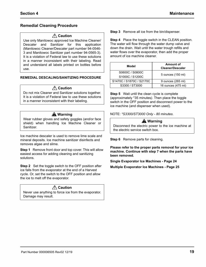
Step 4 Place the toggle switch in the CLEAN position. The water will flow through the water dump valve and down the drain. Wait until the water trough refills and water flows over the evaporator, then add the proper amount of ice machine cleaner.
Step 5 Wait until the clean cycle is complete (approximately *35 minutes). Then place the toggle switch in the OFF position and disconnect power to the ice machine (and dispenser when used).
NOTE: *S3300/ST3000 Only - 80 minutes.
Step 6 Remove parts for cleaning.
Please refer to the proper parts removal for your ice machine. Continue with step 7 when the parts have been removed.Single Evaporator Ice Machines - Page 24Multiple Evaporator Ice Machines - Page 25
! CautionUse only Manitowoc approved Ice Machine Cleaner/Descaler and Sanitizer for this application(Manitowoc Cleaner/Descaler part number 94-0546-3 and Manitowoc Sanitizer part number 94-0565-3).It is a violation of Federal law to use these solutionsin a manner inconsistent with their labeling. Readand understand all labels printed on bottles beforeuse.
! CautionDo not mix Cleaner and Sanitizer solutions together.It is a violation of Federal law to use these solutionsin a manner inconsistent with their labeling.
! WarningWear rubber gloves and safety goggles (and/or faceshield) when handling Ice Machine Cleaner orSanitizer.
! CautionNever use anything to force ice from the evaporator.Damage may result.
Model Amount of Cleaner/Descaler
S0600C / S0800CS1000C / S1200C
5 ounces (150 ml)
S1470C / S1870C / S2170C 9 ounces (265 ml)S3300 / ST3000 16 ounces (475 ml)
! WarningDisconnect the electric power to the ice machine atthe electric service switch box.
Part Number 000006505 Rev02 12/19 19

Maintenance Section 4
Step 7 Mix a solution of cleaner/descaler and warm water. Depending upon the amount of mineral buildup, a larger quantity of solution may be required. Use the ratio in the table below to mix enough solution to thoroughly clean all parts.
Step 8 Use 1/2 of the descaler/water mixture to descale all components. The descaler solution will foam when it contacts lime scale and mineral deposits; once the foaming stops use a soft-bristle nylon brush, sponge or cloth (NOT a wire brush) to carefully clean the parts. Soak parts for 5 minutes (15 - 20 minutes for heavily scaled parts). Rinse all components with clean water.
Step 9 While components are soaking, use 1/2 of the descaler/water solution to clean all foodzone surfaces of the ice machine and bin (or dispenser). Use a nylon brush or cloth to thoroughly descale the following ice machine areas:
• Side walls• Base (area above water trough)• Evaporator plastic parts - including top, bottom, and
sides• Bin or dispenserRinse all areas thoroughly with clean water.SANITIZING PROCEDURE
Step 10 Mix a solution of sanitizer and warm water.
Step 11 Use 1/2 of the sanitizer/water solution to sanitize all removed components. Use a spray bottle to liberally apply the solution to all surfaces of the removed parts or soak the removed parts in the sanitizer/water solution. Do not rinse parts after sanitizing.
Step 12 Use 1/2 of the sanitizer/water solution to sanitize all foodzone surfaces of the ice machine and bin (or dispenser). Use a spray bottle to liberally apply the solution. When sanitizing, pay particular attention to the following areas:
• Side walls• Base (area above water trough)• Evaporator plastic parts - including top, bottom and
sides• Bin or dispenserDo not rinse the sanitized areas.
Step 13 Replace all removed components.
Step 14 Wait 30 minutes.
Step 15 Reapply power to the ice machine and place the toggle switch in the CLEAN position.
Step 16 Wait until the water trough refills and water flows over the evaporator (approximately 3 minutes). Add the proper amount of Manitowoc Ice Machine Sanitizer to the water trough by pouring between the water curtain and evaporator.
Step 17 Move the toggle switch to the ICE position and replace the front panel. The ice machine will automatically start ice making after the sanitize cycle is complete (approximately 35 minutes, S3300C/ST3000C 80 minutes).
Solution Type Water Mixed WithCleaner 1 gal. (4 L) 16 oz (500 ml) cleaner
Solution Type Water Mixed WithSanitizer 6 gal. (23 L) 4 oz (120 ml) sanitizer
Model Amount of SanitizerS0600C / S0800CS1000C / S1200C
3 ounces (90 ml)
S1470C / S1870C / S2170C 12 ounces (355 ml)S3300C / ST3000C 25 ounces (740 ml)
20 Part Number 000006505 Rev02 12/19

Section 4 Maintenance
Detailed Descaling and Sanitizing ProcedureIce machines that are heavily scaled or have not been cleaned on a regular basis will need to run this procedure.Clean and sanitize the ice machine every six months for efficient operation. If the ice machine requires more frequent cleaning and sanitizing, consult a qualified service company to test the water quality and recommend appropriate water treatment. The ice machine must be taken apart for cleaning and sanitizing.
CLEANING PROCEDURE
Ice machine cleaner/descaler is used to remove lime scale and mineral deposits. Ice machine sanitizer disinfects and removes algae and slime.Step 1 Set the toggle switch to the OFF position after ice falls from the evaporator at the end of a Harvest cycle. Or, set the switch to the OFF position and allow the ice to melt off the evaporator.
Step 2 Remove top cover. This will allow easiest access for adding descaling and sanitizing solutions.
Step 3 Remove all ice from the bin.
Step 4 Place the toggle switch in the CLEAN position. The water will flow through the water dump valve and down the drain. Wait until the water trough refills and water flows over the evaporator, then add the proper amount of ice machine cleaner.
Step 5 Wait until the clean cycle is complete (approximately *35 minutes). Then place the toggle switch in the OFF position and disconnect power to the ice machine (and dispenser when used).
NOTE: *S3300C/ST3000C Only - 80 minutes.
Step 6 Remove parts for cleaning.
Please refer to the proper parts removal for your ice machine.Single Evaporator Ice Machines - Page 24Multiple Evaporator Ice Machines - Page 25
! CautionUse only Manitowoc approved Ice Machine Cleaner/Descaler and Sanitizer for this application(Manitowoc Cleaner part number 94-0546-3 andManitowoc Sanitizer part number 94-0565-3). It is aviolation of Federal law to use these solutions in amanner inconsistent with their labeling. Read andunderstand all labels printed on bottles before use
! CautionDo not mix Cleaner/Descaler and Sanitizer solutionstogether. It is a violation of Federal law to use thesesolutions in a manner inconsistent with theirlabeling.
! WarningWear rubber gloves and safety goggles (and/or faceshield) when handling Ice Machine Cleaner orSanitizer.
! CautionNever use anything to force ice from the evaporator.Damage may result.
Model Amount of Cleaner/Descaler
S0600C / S0800CS1000C / S1200C
IB600C / IB800C / IB1000C5 ounces (150 ml)
S1470C / S1870C / S2170C 9 ounces (265 ml)S3300C / ST3000C 16 ounces (475 ml)
! WarningDisconnect the electric power to the ice machine atthe electric service switch box.
Part Number 000006505 Rev02 12/19 21
Maintenance Section 4
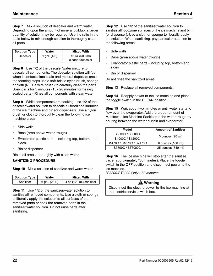
Step 7 Mix a solution of descaler and warm water. Depending upon the amount of mineral buildup, a larger quantity of solution may be required. Use the ratio in the table below to mix enough solution to thoroughly clean all parts.
Step 8 Use 1/2 of the descaler/water mixture to descale all components. The descaler solution will foam when it contacts lime scale and mineral deposits; once the foaming stops use a soft-bristle nylon brush, sponge or cloth (NOT a wire brush) to carefully clean the parts. Soak parts for 5 minutes (15 - 20 minutes for heavily scaled parts). Rinse all components with clean water.
Step 9 While components are soaking, use 1/2 of the descaler/water solution to descale all foodzone surfaces of the ice machine and bin (or dispenser). Use a nylon brush or cloth to thoroughly clean the following ice machine areas:
• Side walls• Base (area above water trough)• Evaporator plastic parts - including top, bottom, and
sides• Bin or dispenserRinse all areas thoroughly with clean water.SANITIZING PROCEDURE
Step 10 Mix a solution of sanitizer and warm water.
Step 11 Use 1/2 of the sanitizer/water solution to sanitize all removed components. Use a cloth or sponge to liberally apply the solution to all surfaces of the removed parts or soak the removed parts in the sanitizer/water solution. Do not rinse parts after sanitizing.
Step 12 Use 1/2 of the sanitizer/water solution to sanitize all foodzone surfaces of the ice machine and bin (or dispenser). Use a cloth or sponge to liberally apply the solution. When sanitizing, pay particular attention to the following areas:
• Side walls• Base (area above water trough)• Evaporator plastic parts - including top, bottom and
sides• Bin or dispenserDo not rinse the sanitized areas.
Step 13 Replace all removed components.
Step 14 Reapply power to the ice machine and place the toggle switch in the CLEAN position.
Step 15 Wait about two minutes or until water starts to flow over the evaporator. Add the proper amount of Manitowoc Ice Machine Sanitizer to the water trough by pouring between the water curtain and evaporator.
Step 16 The ice machine will stop after the sanitize cycle (approximately *35 minutes). Place the toggle switch in the OFF position and disconnect power to the ice machine.*S3300/ST3000 Only - 80 minutes.
Solution Type Water Mixed WithDescaler 1 gal. (4 L) 16 oz (500 ml)
cleaner/descaler
Solution Type Water Mixed WithSanitizer 6 gal. (23 L) 4 oz (120 ml) sanitizer
Model Amount of SanitizerS0600C / S0800CS1000C / S1200C
3 ounces (90 ml)
S1470C / S1870C / S2170C 6 ounces (180 ml)S3300C / ST3000C 25 ounces (740 ml)
! WarningDisconnect the electric power to the ice machine atthe electric service switch box.
22 Part Number 000006505 Rev02 12/19

Section 4 Maintenance
Step 17 Refer to step 6 and disassemble components. After dissembling proceed to step 18.
Step 18 Mix a solution of sanitizer and warm water.
Step 19 Use 1/2 of the sanitizer/water solution to sanitize all removed components. Use a cloth or sponge to liberally apply the solution to all surfaces of the removed parts or soak the removed parts in the sanitizer/water solution. Do not rinse parts after sanitizing.
Step 20 Use 1/2 of the sanitizer/water solution to sanitize all foodzone surfaces of the ice machine and bin (or dispenser). Use a cloth or sponge to liberally apply the solution. When sanitizing, pay particular attention to the following areas:
• Side walls• Base (area above water trough)• Evaporator plastic parts - including top, bottom and
sides• Bin or dispenserDo not rinse the sanitized areas.
Step 21 Install the removed parts, restore power and place the toggle switch in the ICE position.
Solution Type Water Mixed WithSanitizer 6 gal. (23 L) 4 oz (120 ml) sanitizer
Part Number 000006505 Rev02 12/19 23

Maintenance Section 4
Parts Removal for Cleaning/SanitizingSingle Evaporator Ice MachinesA. Remove the water curtain• Gently flex the curtain in the center and remove it
from the right side.• Slide the left pin out.B. Remove the ice thickness probe• Compress the hinge pin on the top of the ice
thickness probe.• Pivot the ice thickness probe to disengage one pin
then the other. The ice thickness probe can be cleaned at this point without complete removal. If complete removal is desired, disconnect the ice thickness control wiring from the control board.
C. Remove the evaporator tray or water diverter from the bottom of the evaporator
• Loosen thumbscrew on left side of tray.• Allow left side of tray to drop as you pull the tray to
the left side. Continue until the outlet tube disengages from the right side.
D. Remove the water trough• Depress tabs on right and left side of the water
trough.• Allow front of water trough to drop as you pull forward
to disengage the rear pins.E. Remove the water level probe• Pull the water level probe straight down to
disengage.
• Lower the water level probe until the wiring connector is visible.
• Disconnect the wire lead from the water level probe.• Remove the water level probe from the ice machine.F. Remove the water pump• Grasp pump and pull straight down on pump
assembly until water pump disengages and electrical connector is visible.
• Disconnect the electrical connector.• Remove the water pump assembly from ice machine.• Do not soak the water pump motor in cleaner or
sanitizer solution.G. Remove the water distribution tubeNOTE: Distribution tube thumbscrews are retained to prevent loss. Loosen thumbscrews but do not pull thumbscrews out of distribution tube.• Loosen the two outer screws (do not remove screws
completely they are retained to prevent loss) and pull forward on the distribution tube to release from slip joint.
• Disassemble distribution tube by loosening the two (2) middle thumbscrews and dividing the distribution tube into two pieces.
G
A
BE
CD
F
24 Part Number 000006505 Rev02 12/19
Section 4 Maintenance
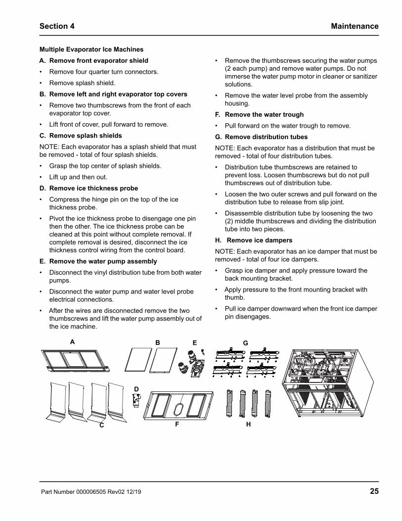
Multiple Evaporator Ice MachinesA. Remove front evaporator shield• Remove four quarter turn connectors.• Remove splash shield.B. Remove left and right evaporator top covers• Remove two thumbscrews from the front of each
evaporator top cover.• Lift front of cover, pull forward to remove.C. Remove splash shieldsNOTE: Each evaporator has a splash shield that must be removed - total of four splash shields.• Grasp the top center of splash shields.• Lift up and then out.D. Remove ice thickness probe• Compress the hinge pin on the top of the ice
thickness probe.• Pivot the ice thickness probe to disengage one pin
then the other. The ice thickness probe can be cleaned at this point without complete removal. If complete removal is desired, disconnect the ice thickness control wiring from the control board.
E. Remove the water pump assembly• Disconnect the vinyl distribution tube from both water
pumps.• Disconnect the water pump and water level probe
electrical connections.• After the wires are disconnected remove the two
thumbscrews and lift the water pump assembly out of the ice machine.
• Remove the thumbscrews securing the water pumps (2 each pump) and remove water pumps. Do not immerse the water pump motor in cleaner or sanitizer solutions.
• Remove the water level probe from the assembly housing.
F. Remove the water trough• Pull forward on the water trough to remove. G. Remove distribution tubesNOTE: Each evaporator has a distribution that must be removed - total of four distribution tubes.• Distribution tube thumbscrews are retained to
prevent loss. Loosen thumbscrews but do not pull thumbscrews out of distribution tube.
• Loosen the two outer screws and pull forward on the distribution tube to release from slip joint.
• Disassemble distribution tube by loosening the two (2) middle thumbscrews and dividing the distribution tube into two pieces.
H. Remove ice dampersNOTE: Each evaporator has an ice damper that must be removed - total of four ice dampers.• Grasp ice damper and apply pressure toward the
back mounting bracket.• Apply pressure to the front mounting bracket with
thumb.• Pull ice damper downward when the front ice damper
pin disengages.
A B
C
D
E
F
G
H
Part Number 000006505 Rev02 12/19 25

Maintenance Section 4
Exterior CleaningClean the area around the ice machine as often as necessary to maintain cleanliness and efficient operation. Use cleaners designed for use with stainless steel products.Sponge any dust and dirt off the outside of the ice machine with mild soap and water. Wipe dry with a clean, soft cloth.Heavy stains should be removed with stainless steel wool. Never use plain steel wool or abrasive pads. They will scratch the panels.
Door Removal1. Use a fillips screwdriver to loosen the two screws
securing the left and right doors. Do not remove they are secured to prevent loss.
2. 30 Inch and 48 Inch Models: To remove right front door lift up and remove (22 inch ice machines have a single door, lift to remove entire door).
Door Removal
3. Open left front door to 45 degrees. 4. Support with right hand, depress top pin, tilt top of
door forward and lift out of bottom pin to remove.
Cleaning the CondenserGENERAL
A dirty condenser restricts airflow, resulting in excessively high operating temperatures. This reduces ice production and shortens component life.• Clean the condenser at least every six months.
• Shine a flashlight through the condenser to check for dirt between the fins.
• Blow compressed air or rinse with water from the inside out (opposite direction of airflow).
• If dirt still remains call a service agent to clean the condenser.
Removal from Service/Winterization1. Clean and sanitize the ice machine.2. Move the ICE/OFF/CLEAN switch to OFF.3. Turn off the water supply, disconnect and drain the
incoming ice-making water line at the rear of the ice machine and drain the water trough.
4. Energize the ice machine, wait one minute for the water inlet valve to open and blow compressed air in both the incoming water and the drain openings in the rear of the ice machine to remove all water.
5. Move ICE/OFF/CLEAN switch to OFF and disconnect the electric power at the circuit breaker or the electric service switch.
6. Fill spray bottle with sanitizer and spray all interior food zone surfaces. Do not rinse and allow to air dry.
7. Replace all panels.
2
1
4
! WarningDisconnect electric power to the ice machine headsection and the remote condensing unit at theelectric service switches before cleaning thecondenser.
! WarningThe condenser fins are sharp. Use care whencleaning them.
26 Part Number 000006505 Rev02 12/19

Section 5Customer Support
Before Calling for Service ChecklistIf a problem arises during operation of your ice machine, follow the checklist below before calling service. Routine adjustments and maintenance procedures are not covered by the warranty.
Problem Possible Cause To CorrectIce machine does not operate. No electrical power to the ice machine and/or
condensing unit.Replace the fuse/reset the breaker/turn on the main switch.
High pressure cutout tripping. Clean condenser coil. (See Section 4)ICE/OFF/CLEAN toggle switch set improperly.
Move the toggle switch to the ICE position.
Water curtain stuck open. Water curtain or ice damper must be installed and swinging freely. (See Section 4)
Remote receiver service valve and/or Liquid/suction line shut off valves are closed.
Open the valve(s). (See Section 2)
IB Only - Dispenser level thermostat open. Adjust thermostat to maintain correct dispenser level.
Ice machine stops, and can be restarted by moving the toggle switch to OFF and back to ICE.
Safety limit feature stopping the ice machine. Refer to “Safety Limit Feature” on the next page.
Ice machine does not release ice or is slow to harvest.
Ice machine is dirty. Clean and sanitize the ice machine. (See Section 4)
Ice machine is not level. Level the ice machine. (See Section 2)Low air temperature around ice machine head section.
Air temperature must be at least 35°F (1.6°C).
Fan cycling control does not de-energize condenser fan motor.
Verify pressure is below cut-out setpoint, replace fan cycling control.
CVD1486 - Water regulating valve incorrectly adjusted or will not close.
Check for water at condenser water drain outlet. Contact a qualified service company to adjust/replace valve.
Ice machine does not cycle into harvest mode.
The six-minute freeze time lock-in has not expired yet.
Wait for the freeze lock-in to expire.
Ice thickness probe is dirty. Clean and sanitize the ice machine. (See Section 4)
Ice thickness probe is disconnected. Connect the wire.Ice thickness probe is out of adjustment. Adjust the ice thickness probe. (See Section 3)Uneven ice fill (thin at the top of evaporator). Verify sufficient water level in sump trough.
Contact a qualified service company to check refrigeration system.
Ice quality is poor (soft or not clear).
Poor incoming water quality. Contact a qualified service company to test the quality of the incoming water and make appropriate filter recommendations.
Water filtration is poor. Replace the filter.Ice machine is dirty. Clean and sanitize the ice machine.
(See Section 4)Water dump valve is not working. Disassemble and clean the water dump valve.
(See Section 4)Water softener is working improperly (if applicable).
Repair the water softener.
Part Number 000006505 Rev02 12/19 27
Customer Support Section 5
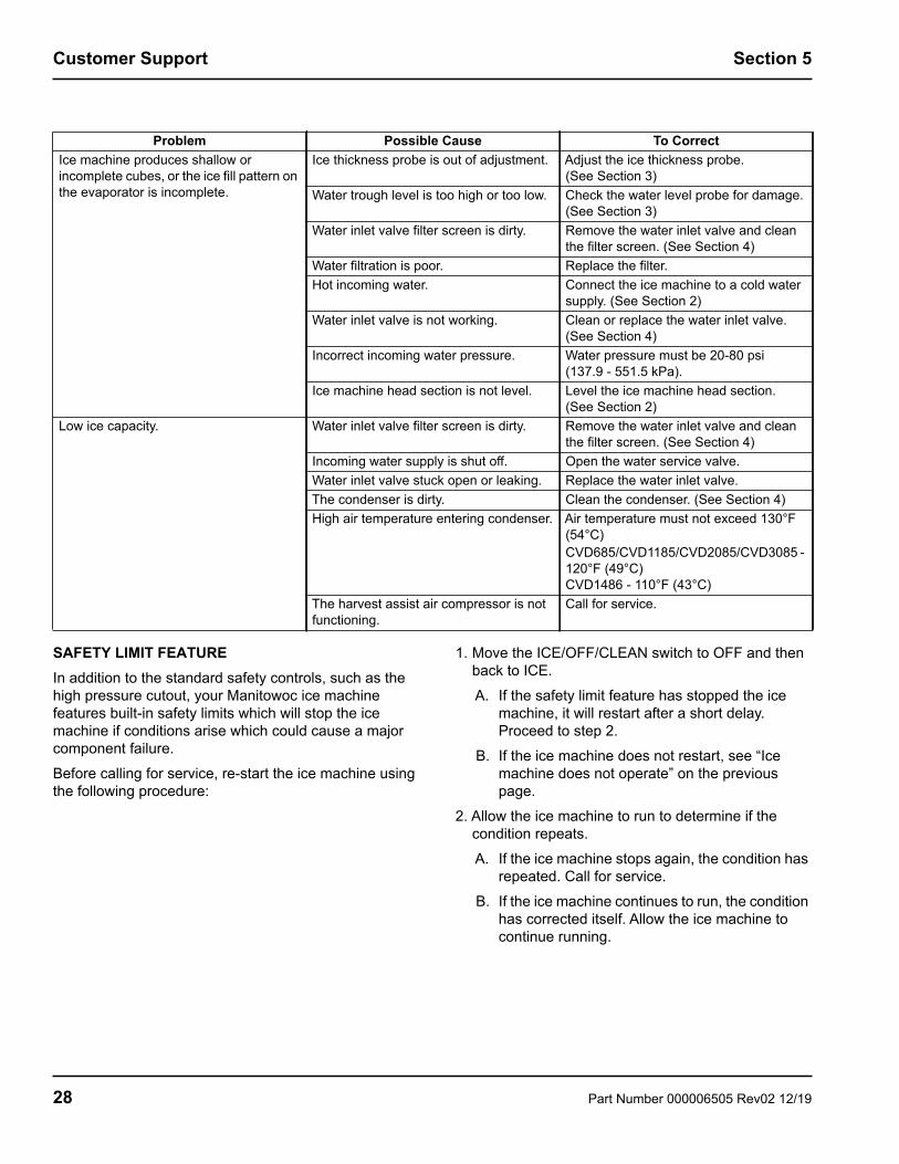
SAFETY LIMIT FEATUREIn addition to the standard safety controls, such as the high pressure cutout, your Manitowoc ice machine features built-in safety limits which will stop the ice machine if conditions arise which could cause a major component failure.Before calling for service, re-start the ice machine using the following procedure:
1. Move the ICE/OFF/CLEAN switch to OFF and then back to ICE.A. If the safety limit feature has stopped the ice
machine, it will restart after a short delay. Proceed to step 2.
B. If the ice machine does not restart, see “Ice machine does not operate” on the previous page.
2. Allow the ice machine to run to determine if the condition repeats.A. If the ice machine stops again, the condition has
repeated. Call for service.B. If the ice machine continues to run, the condition
has corrected itself. Allow the ice machine to continue running.
Problem Possible Cause To CorrectIce machine produces shallow or incomplete cubes, or the ice fill pattern on the evaporator is incomplete.
Ice thickness probe is out of adjustment. Adjust the ice thickness probe. (See Section 3)
Water trough level is too high or too low. Check the water level probe for damage. (See Section 3)
Water inlet valve filter screen is dirty. Remove the water inlet valve and clean the filter screen. (See Section 4)
Water filtration is poor. Replace the filter.Hot incoming water. Connect the ice machine to a cold water
supply. (See Section 2)Water inlet valve is not working. Clean or replace the water inlet valve.
(See Section 4)Incorrect incoming water pressure. Water pressure must be 20-80 psi
(137.9 - 551.5 kPa). Ice machine head section is not level. Level the ice machine head section.
(See Section 2)Low ice capacity. Water inlet valve filter screen is dirty. Remove the water inlet valve and clean
the filter screen. (See Section 4)Incoming water supply is shut off. Open the water service valve.Water inlet valve stuck open or leaking. Replace the water inlet valve.The condenser is dirty. Clean the condenser. (See Section 4)High air temperature entering condenser. Air temperature must not exceed 130°F
(54°C)CVD685/CVD1185/CVD2085/CVD3085 - 120°F (49°C)CVD1486 - 110°F (43°C)
The harvest assist air compressor is not functioning.
Call for service.
28 Part Number 000006505 Rev02 12/19

Section 5 Customer Support
Commercial Ice Machine WarrantyManitowoc Ice, Inc. (hereinafter referred to as the “COMPANY”) warrants for a period of thirty-six months from the installation date(except as limited below) that new ice machines manufactured by the COMPANY shall be free of defects in material orworkmanship under normal and proper use and maintenance as specified by the COMPANY and upon proper installation andstart-up in accordance with the instruction manual supplied with the ice machine. The COMPANY’S warranty hereunder withrespect to the compressor shall apply for an additional twenty-four months, excluding all labor charges, and with respect to theevaporator for an additional twenty-four months, including labor charges.
The obligation of the COMPANY under this warranty is limited to the repair or replacement of parts, components, or assembliesthat in the opinion of the COMPANY are defective. This warranty is further limited to the cost of parts, components or assembliesand standard straight time labor charges at the servicing location.
Time and hourly rate schedules, as published from time to time by the COMPANY, apply to all service procedures. Additionalexpenses including without limitation, travel time, overtime premium, material cost, accessing or removal of the ice machine, orshipping are the responsibility of the owner, along with all maintenance, adjustments, cleaning, and ice purchases. Labor coveredunder this warranty must be performed by a COMPANY Contracted Service Representative or a refrigeration service agency asqualified and authorized by the COMPANY'S local Distributor. The COMPANY'S liability under this warranty shall in no event begreater than the actual purchase price paid by customer for the ice machine.
The foregoing warranty shall not apply to (1) any part or assembly that has been altered, modified, or changed; (2) any part orassembly that has been subjected to misuse, abuse, neglect, or accidents; (3) any ice machine that has been installed and/ormaintained inconsistent with the technical instructions provided by the COMPANY; or (4) any ice machine initially installed morethan five years from the serial number production date. This warranty shall not apply if the Ice Machine’s refrigeration system ismodified with a condenser, heat reclaim device, or parts and assemblies other than those manufactured by the COMPANY, unlessthe COMPANY approves these modifications for specific locations in writing.THIS WARRANTY IS IN LIEU OF ALL OTHER WARRANTIES OR GUARANTEES OF ANY KIND, EXPRESSED OR IMPLIED, INCLUDING ANY IMPLIED WARRANTY OF MERCHANTABILITY OR FITNESS FOR A PARTICULAR PURPOSE. In no event shall the COMPANY be liable for any special, indirect, incidental or consequential damages. Upon the expiration of the warranty period, the COMPANY’S liability under this warranty shall terminate. The foregoing warranty shall constitute the sole liability of the COMPANY and the exclusive remedy of the customer or user.
To secure prompt and continuing warranty service, the warranty registration card must be completed and sent to the COMPANY within five (5) days from the installation date.Complete the following and retain for your record:Distributor/Dealer Model Number Serial Number Installation Date
MANITOWOC ICE, INC.2110 So. 26th St., P.O. Box 1720, Manitowoc, WI 54221-1720Telephone: 920-682-0161 Fax: 920-683-7585Web Site - www.manitowocice.comForm 80-0373-3 Rev. 01/02
Part Number 000006505 Rev02 12/19 29

Customer Support Section 5
Residential Ice Machine Limited WarrantyWHAT DOES THIS LIMITED WARRANTY COVER?Subject to the exclusions and limitations below, Manitowoc Food-service (“Manitowoc”) warrants to the original consumer that any new ice machine manufactured by Manitowoc (the “Product”) shall be free of defects in material or workmanship for the warranty period outlined below under normal use and maintenance, and upon proper installation and start-up in accordance with the instruction manual supplied with the Product.
HOW LONG DOES THIS LIMITED WARRANTY LAST?Product Covered Warranty Period Ice Machine Twelve (12) months
from the sale date
WHO IS COVERED BY THIS LIMITED WARRANTY?This limited warranty only applies to the original consumer of the Product and is not transferable.
WHAT ARE MANITOWOC ICE’S OBLIGATIONS UNDER THIS LIMITED WARRANTY?If a defect arises and Manitowoc receives a valid warranty claim prior to the expiration of the warranty period, Manitowoc shall, at its option: (1) repair the Product at Manitowoc’s cost, including standard straight time labor charges, (2) replace the Product with one that is new or at least as functionally equivalent as the original, or (3) refund the purchase price for the Product. Replacement parts are warranted for 90 days or the balance of the original warranty period, whichever is longer. The foregoing constitutes Manitowoc’s sole obligation and the consumer’s exclusive remedy for any breach of this limited warranty. Manitowoc’s liability under this limited warranty is limited to the purchase price of Product. Additional expenses including, without limitation, service travel time, overtime or premium labor charges, accessing or removing the Product, or shipping are the responsibility of the consumer.
HOW TO OBTAIN WARRANTY SERVICETo obtain warranty service or information regarding your Product, please contact us at:MANITOWOC FOODSERVICE2110 So. 26th St.P.O. Box 1720,Manitowoc, WI 54221-1720Telephone: 920-682-0161 Fax: 920-683-7585www.manitowocice.com
WHAT IS NOT COVERED? This limited warranty does not cover, and you are solely responsible for the costs of: (1) periodic or routine maintenance, (2) repair or replacement of the Product or parts due to normal wear and tear, (3) defects or damage to the Product or parts resulting from misuse, abuse, neglect, or accidents, (4) defects or damage to the Product or parts resulting from improper or unauthorized alterations, modifications, or changes; and (5) defects or damage to any Product that has not been installed and/or maintained in accordance with the instruction manual or technical instructions provided by Manitowoc. To the extent that warranty exclusions are not permitted under some state laws, these exclusions may not apply to you.
EXCEPT AS STATED IN THE FOLLOWING SENTENCE, THIS LIMITED WARRANTY IS THE SOLE AND EXCLUSIVE WARRANTY OF MANITOWOC WITH REGARD TO THE PRODUCT. ALL IMPLIED WARRANTIES ARE STRICTLY LIMITED TO THE DURATION OF THE LIMITED WARRANTY APPLICABLE TO THE PRODUCTS AS STATED ABOVE, INCLUDING BUT NOT LIMITED TO, ANY WARRANTY OF MERCHANTABILITY OR OF FITNESS FOR A PARTICULAR PURPOSE. Some states do not allow limitations on how long an implied warranty lasts, so the above limitation may not apply to you.
IN NO EVENT SHALL MANITOWOC OR ANY OF ITS AFFILIATES BE LIABLE TO THE CONSUMER OR ANY OTHER PERSON FOR ANY INCIDENTAL, CONSEQUENTIAL OR SPECIAL DAMAGES OF ANY KIND (INCLUDING, WITHOUT LIMITATION, LOSS PROFITS, REVENUE OR BUSINESS) ARISING FROM OR IN ANY MANNER CONNECTED WITH THE PRODUCT, ANY BREACH OF THIS LIMITED WARRANTY, OR ANY OTHER CAUSE WHATSOEVER, WHETHER BASED ON CONTRACT, TORT OR ANY OTHER THEORY OF LIABILITY. Some states do not allow the exclusion or limitation of incidental or consequential damages, so the above limitation or exclusion may not apply to you.
HOW STATE LAW APPLIES This limited warranty gives you specific legal rights, and you may also have rights that vary from state to state or from one jurisdiction to another.
REGISTRATION CARDTo secure prompt and continuing warranty service, this warranty registration card must be completed and sent to Manitowoc within thirty (30) days from the sale date. Complete the following registration card and send it to Manitowoc.
30 Part Number 000006505 Rev02 12/19


Manitowoc Ice2110 South 26th Street Manitowoc, WI
54220800-545-5720
www.manitowocice.com
© 2019 Welbilt Inc. except where explicitly stated otherwise. All rights reserved.Part Number 000006505 Rev02 12/19